

Page 1

Americas Headquarters
Cisco Systems, Inc.
170 West Tasman Drive
San Jose, CA 95134-1706
USA
http://www.cisco.com
Tel: 408 526-4000
800 553-NETS (6387)
Fax: 408 527-0883
Cisco 7301 Installation and Configuration
Guide
Product Number: Cisco 7301
THE SPECIFICATIONS AND INFORMATION REGARDING THE PRODUCTS IN THIS MANUAL ARE SUBJECT TO
CHANGE WITHOUT NOTICE. ALL STATEMENTS, INFORMATION, AND RECOMMENDATIONS IN THIS
MANUAL ARE BELIEVED TO BE ACCURATE BUT ARE PRESENTED WITHOUT WARRANTY OF ANY KIND,
EXPRESS OR IMPLIED. USERS MUST TAKE FULL RESPONSIBILITY FOR THEIR APPLICATION OF ANY
PRODUCTS.
Customer Order Number:
Text Part Number: OL-5418-07
Page 2

THE SOFTWARE LICENSE AND LIMITED WARRANTY FOR THE ACCOMPANYING PRODUCT ARE SET FORTH IN THE INFORMATION PACKET THAT
SHIPPED WITH THE PRODUCT AND ARE INCORPORATED HEREIN BY THIS REFERENCE. IF YOU ARE UNABLE TO LOCATE THE SOFTWARE LICENSE
OR LIMITED WARRANTY, CONTACT YOUR CISCO REPRESENTATIVE FOR A COPY.
The following inform ation is for FCC compliance of Class A devices:
This equipment has been tested and found to comply with the limits for a Class A digital device, pursuant
to part 15 of the FCC rules. These limits are designed to provide reasonable protection against harmful interference when the equipment is operated in a commercial
environment. This equipment generates, uses, and can radiate radio-frequency energy and, if not installed and used in accordance with the instruction manual, may cause
harmful interference to radio communications. Operation of this equipment in a residential area is likely to cause harmful interference, in which case users will be required
to correct the interference at their own expense.
The following information is for FCC compliance of Class B devices: The equipment described in this manual generates and may radi
ate radio-frequency energy. If it is not
installed in accordance with Cisco’s installation instructions, it may cause interference with radio and television reception. This equipment has been tested and found to
comply with the limits for a Class B digital device in accordance with the specifications in part 15 of the FCC rules. These specifications are designed to provide reasonable
protection against such interference in a residential installation. However, there is no guarantee that interference will not occur in a particular installation.
Modifying the equipment without Cisco’s written authorization may result in the equipment no longer complying with FCC requiremen
ts for Class A or Class B digital
devices. In that event, your right to use the equipment may be limited by FCC regulations, and you may be required to correct any interference to radio or television
communications at your own expense.
You can determine whether your equipment is causing interference by turning it off. If the interference stops, it was probably caus
ed by the Cisco equipment or one of its
peripheral devices. If the equipment causes interference to radio or television reception, try to correct the interference by using one or more of the following measures:
• Turn the television or radio antenna until the interference stops.
• Move the equipment to one side or the other of the television or radio.
• Move the equipment farther away from the television or radio.
• Plug the equipment into an outlet that is on a different circuit from the television or radio. (That is, make certain the equip
ment and the television or radio are on circuits
controlled by different circuit breakers or fuses.)
Modifications to this product not authorized by Cisco Systems, Inc. could void the FCC approval and negate your authority to oper
ate the product.
The Cisco implementation of TCP header compression is an adaptation of a program developed by the University of California, Berk
eley (UCB) as part of UCB’s public
domain version of the UNIX operating system. All rights reserved. Copyright © 1981, Regents of the University of California.
NOTWITHSTANDING ANY OTHER WARRANTY HEREIN, ALL DOCUMENT FILES AND SOFTWARE OF THESE SUPPLIERS ARE PROVIDED “AS IS” WITH
AL
L FAULTS. CISCO AND THE ABOVE-NAMED SUPPLIERS DISCLAIM ALL WARRANTIES, EXPRESSED OR IMPLIED, INCLUDING, WITHOUT
L
IMITATION, THOSE OF MERCHANTABILITY, FITNESS FOR A PARTICULAR PURPOSE AND NONINFRINGEMENT OR ARISING FROM A COURSE OF
DEALING, USAGE, OR TRADE PRACTICE.
IN NO EVENT SHALL CISCO OR ITS SUPPLIERS BE LIABLE FOR ANY INDIRECT, SPECIAL, CONSEQUENTIAL, OR INCIDENTAL DAMAGES, INCLUDING,
WI
THOUT LIMITATION, LOST PROFITS OR LOSS OR DAMAGE TO DATA ARISING OUT OF THE USE OR INABILITY TO USE THIS MANUAL, EVEN IF CISCO
OR ITS SUPPLIERS HAVE BEEN ADVISED OF THE POSSIBILITY OF SUCH DAMAGES.
CCDE, CCENT, CCSI, Cisco Eos, Cisco HealthPresence, Cisco Ironport, the Cisco logo, Cisco Lumin, Cisco Nexus, Cisco Nurse Connect
, Cisco Stackpower,
Cisco StadiumVision, Cisco TelePresence, Cisco Unified Computing System, Cisco WebEx, DCE, Flip Channels, Flip for Good, Flip Mino, Flip Video, Flip Video (Design),
Fl
ipshare (Design), Flip Ultra, and Welcome to the Human Network are trademarks; Changing the Way We Work, Live, Play, and Learn, Cisco Store, and Flip Gift Card are
ser
vice marks; and Access Registrar, Aironet, AsyncOS, Bringing the Meeting To You, Catalyst, CCDA, CCDP, CCIE, CCIP, CCNA, CCNP, CCSP, CCVP, Cisco, the
Cisco Certified Internetwork Expert logo, Cisco IOS, Cisco Press, Cisco Systems, Cisco Systems Capital, the Cisco Systems logo, Cisco Unity, Collaboration Without
L
imitation, EtherFast, EtherSwitch, Event Center, Fast Step, Follow Me Browsing, FormShare, GigaDrive, HomeLink, Internet Quotient, IOS, iPhone, iQuick Study,
IronPort, the IronPort logo, LightStream, Linksys, MediaTone, MeetingPlace, MeetingPlace Chime Sound, MGX, Networkers, Networking Academy, Network Registrar,
P
CNow, PIX, PowerPanels, ProConnect, ScriptShare, SenderBase, SMARTnet, Spectrum Expert, StackWise, The Fastest Way to Increase Your Internet Quotient, TransPath,
WebEx, and the WebEx logo are registered trademarks of Cisco Systems, Inc. and/or its affiliates in the United States and certain other countries.
All other trademarks mentioned in this document or website are the property of their respective owners. The use of the word partn
er does not imply a partnership relationship
between Cisco and any other company. (0907R)
Cisco 7301 Installation and Configuration Guide
Copyright © 2009 Cisco Systems, Inc. All rights reserved.
Page 3

3
Cisco 7301 Installation and Configuration Guide
OL-5418-07
CONTENTS
Preface iii
Document Version History iii
Document Objectives iii
Audience iv
Document Organization iv
Warning Definition v
Related Documentation x
Obtaining Documentation and Submitting a Service Request xi
CHAPTER
1 Cisco 7301 Overview 1-1
Cisco 7301 Features 1-2
Cisco 7301 Hardware Overview 1-3
Front View 1-4
LEDs 1-5
Rear View 1-6
System Board 1-6
System Management Functions 1-7
Checking the Shipping Container Contents 1-7
Cisco 7301 Router Installation Checklist 1-8
About the SFP GBIC Module 1-9
Installing the SFP GBIC Module 1-11
CHAPTER
2 Rack-Mounting, Tabletop Installation, and Cabling 2-1
Preparing to Install the Cisco 7301 Router 2-1
Tools and Parts Required 2-2
Electrical Equipment Guidelines 2-3
Preventing Electrostatic Discharge Damage 2-3
Site Requirement Guidelines 2-4
Installing the Router 2-4
General Tabletop or Workbench Installation 2-5
Rack-Mounting a Cisco 7301 Router 2-6
Attaching the Chassis Rack-Mount and Cable-Management Brackets 2-6
Installing Rack-Mount Brackets on the Front of the Chassis 2-7
Page 4

Contents
4
Cisco 7301 Installation and Configuration Guide
OL-5418-07
Attaching the Cable-Management Bracket 2-8
Installing Rack-Mount Brackets on the Rear of the Chassis 2-8
Installing the Chassis in the Rack 2-9
Two-Post Rack Installation 2-10
Four-Post Rack Installation 2-11
Attaching a Chassis Ground Connection 2-12
Connecting Port Adapter Cables 2-14
Connecting I/O Cables 2-14
Connecting Console and Auxiliary Port Cables 2-14
Connecting Native Gigabit Ethernet Cables 2-16
Attaching the Gigabit Ethernet Cables 2-16
Attaching the SFP GBIC Interface Cables 2-17
Attaching the Mode-Conditioning Patch Cord 2-19
Attaching the Alarm Port Cable 2-21
Using the Cable-Management Bracket 2-21
Connecting Power 2-22
Connecting AC-Input Power 2-22
Connecting DC-Input Power 2-23
CHAPTER
3 Starting and Configuring the Router 3-1
Functional Overview 3-1
Chassis Slot and Logical Interface Numbering 3-2
MAC Address 3-3
Online Insertion and Removal 3-4
Environmental Monitoring and Reporting Functions 3-5
Environmental Monitoring 3-5
Reporting Functions 3-6
Fan Failures 3-8
Checking Conditions Prior to System Startup 3-8
Starting the System and Observing Initial Conditions 3-9
Configuring a Cisco 7301 Router 3-10
Performing a Basic Configuration Using AutoInstall 3-10
Performing a Basic Configuration Using the Setup Facility 3-11
Configuring Global Parameters 3-11
Configuring the Native Gigabit Ethernet Interfaces 3-14
Configuring Port Adapter Interfaces 3-16
Performing a Basic Configuration Using Global Configuration Mode 3-20
Enabling the Second Processor 3-20
Page 5

Contents
5
Cisco 7301 Installation and Configuration Guide
OL-5418-07
Error Messages 3-22
Using show Commands to Check the Installation 3-22
Using the show interface stats Command 3-22
Using the show ip interface Command 3-22
Using the show mpf cpu Command 3-23
Using the show mpf cpu history Command 3-23
Using the show mpf interface Command 3-24
Using the show mpf ip exact-route Command 3-26
Using the show mpf punt Command 3-26
Using the show version Command 3-26
Saving the Running Configuration to NVRAM 3-27
Checking the Running Configuration Settings 3-27
Performing Other Configuration Tasks 3-27
Upgrading ROMmon on the Cisco 7301 3-27
Using the show rom-monitor Command and showmon Commands 3-28
Using the upgrade rom-monitor Command 3-28
Changing Preferences to Choose the Other ROMmon Image 3-29
Troubleshooting the Upgrade 3-30
ROMmon Upgrade Error Messages 3-30
Replacing or Recovering a Lost Password 3-31
Overview of the Password Recovery Procedure 3-31
Details of the Password Recovery Procedure 3-32
Viewing Your System Configuration 3-34
Performing Complex Configurations 3-35
CHAPTER
4 Installing and Removing Field-Replaceable Units 4-1
Installing and Removing the CompactFlash Disk 4-2
About CompactFlash Disks 4-2
Installing and Removing a Port Adapter or Service Adapter 4-3
Powering Off the Router and Removing the Cover 4-4
Removing and Installing the SODIMMs 4-5
Replacing the Cover and Powering On the Router 4-7
CHAPTER
5 Troubleshooting Initial Startup Problems 5-1
Troubleshooting Overview 5-1
Online Troubleshooting Resources 5-2
Problem Solving Using a Subsystems Approach 5-3
Identifying Startup Problems 5-3
Page 6

Contents
6
Cisco 7301 Installation and Configuration Guide
OL-5418-07
Troubleshooting the Power Subsystem 5-4
Troubleshooting the Cooling Subsystem 5-5
Troubleshooting the I/O Subsystem 5-7
Troubleshooting the Processor Subsystem 5-7
Troubleshooting the Port Adapter or Service Adapter 5-8
Upgrading the Boot Helper (Boot Loader) Image 5-8
Cleaning the Fiber-Optic Connections 5-9
APPENDIX
A Specifications A-1
Cisco 7301 Router Specifications A-1
Software Requirements A-2
Processor and Memory Specifications A-3
SFP GBIC Module Configurations A-4
Gigabit Ethernet RJ-45 Port Pinouts A-5
Console Port and Auxiliary Port Signals and Pinouts A-8
Alarm Port A-9
Lithium Battery Caution A-9
APPENDIX
B Using the CompactFlash Disk B-1
Product Description B-1
Hardware and Software Requirements B-2
Tools and Parts Required B-2
Compatibility Requirements B-2
System Memory and Software Image Functions and Interactions B-3
Boot Environment Variables B-4
Sample Upgrade Process B-5
Working with a CompactFlash Disk B-5
Software Command Overview B-6
Using Software Commands B-7
Using the cd Command B-8
Using the show Command B-8
Using the pwd Command B-9
Using the dir Command B-9
Using the format Command B-9
Using the mkdir Command B-10
Using the rmdir Command B-11
Using the delete Command B-11
Page 7

Contents
7
Cisco 7301 Installation and Configuration Guide
OL-5418-07
Enabling Booting from a CompactFlash Disk B-12
Making a CompactFlash Disk-Based Software Image the Bootable
Software Image
B-13
APPENDIX
C Configuration Register Information C-1
Configuration Bit Meanings C-1
Bits 0–3 C-2
Bit 6 C-3
Bit 7 C-3
Bit 8 C-4
Bit 10 and Bit 14 C-4
Bit 11 and Bit 12 C-4
Bit 13 C-4
Bit 15 C-5
Displaying the Configuration Register While Running Cisco IOS C-5
Displaying the Configuration Register While Running ROM Monitor C-5
Setting the Configuration Register While Running Cisco IOS C-6
Setting the Configuration Register While Running ROM Monitor C-6
I
NDEX
Page 8

Contents
8
Cisco 7301 Installation and Configuration Guide
OL-5418-07
Page 9

iii
Cisco 7301 Installation and Configuration Guide
OL-5418-07
Preface
This preface discusses the objectives, audience, organization, and conventions of this publication. The
following sections are in this chapter:
• Document Version History, page iii
• Document Objectives, page iii
• Audience, page iv
• Document Organization, page iv
• Related Documentation, page x
• Obtaining Documentation and Submitting a Service Request, page xi
Document Version History
The version history of this document is provided below beginning with version OL-5418-06.
Document Objectives
This publication describes the installation and configuration of the Cisco 7301 router, replacement or
upgrading of field replaceable units (FRUs), and troubleshooting of the Cisco 7301 hardware. The
purpose of this guide is to enable the safe and efficient installation of the Cisco 7301 router.
Version Date Notes
OL-5418-07 August 11, 2005 Adding more second cpu sho
w commands and output
Adding statement numbers to warnings and adding the
con
sole port cable kit product number.
Page 10

iv
Cisco 7301 Installation and Configuration Guide
OL-5418-07
Preface
Audience
Audience
This publication is primarily designed for the person responsible for installing, maintaining, and
troubleshooting the Cisco 7301 router. The users of this guide should be familiar with electronic
circuitry and wiring practices and have experience as electronic or electromechanical technicians. Users
of this guide should also have experience in installing high-end networking equipment. Certain
procedures described in this guide require a certified electrician.
For configuration applications, refer to the Cisco IOS configuration guides and command references and
to
the documents listed in the “Related Documentation” section on page x at the end of this preface.
Document Organization
The major sections of this installation and configuration guide are as follows:
Chapter /Appendix Number and Title Description
Chapter 1, “Cisco 7301 Overview” This chapter provides a hardware overview as well as
i
nstallation instructions for a small form factor (SPF)
Gigabit Interface Converter (GBIC) module.
Chapter 2, “Rack-Mounting, Tabletop Installation, and Cabling” This chapter provides preparation and installation
in
structions for installing the chassis in a rack and for
attaching cables.
Chapter 3, “Starting and Configuring the Router” This chapter provides a functional overview of the
syst
em as well as startup and configuration instructions.
Chapter 4, “Installing and Removing Field-Replaceable Units” This chapter provides instructions for removing and
re
placing power supplies, SODIMMs, fans,
CompactFlash disks, and port adapters.
Chapter 5, “Troubleshooting Initial Startup Problems” This chapter provides basic system startup
t
roubleshooting information.
Appendix A, “Specifications” This appendix provides system specifications as well as
por
t and cabling pinouts and specifications.
Appendix B, “Using the CompactFlash Disk” This appendix provides instructions for using the
Co
mpactFlash Disk.
Appendix C, “Configuration Register Information” This appendix provides configuration register
i
nformation.
Page 11

v
Cisco 7301 Installation and Configuration Guide
OL-5418-07
Preface
Document Organization
Warning Definition
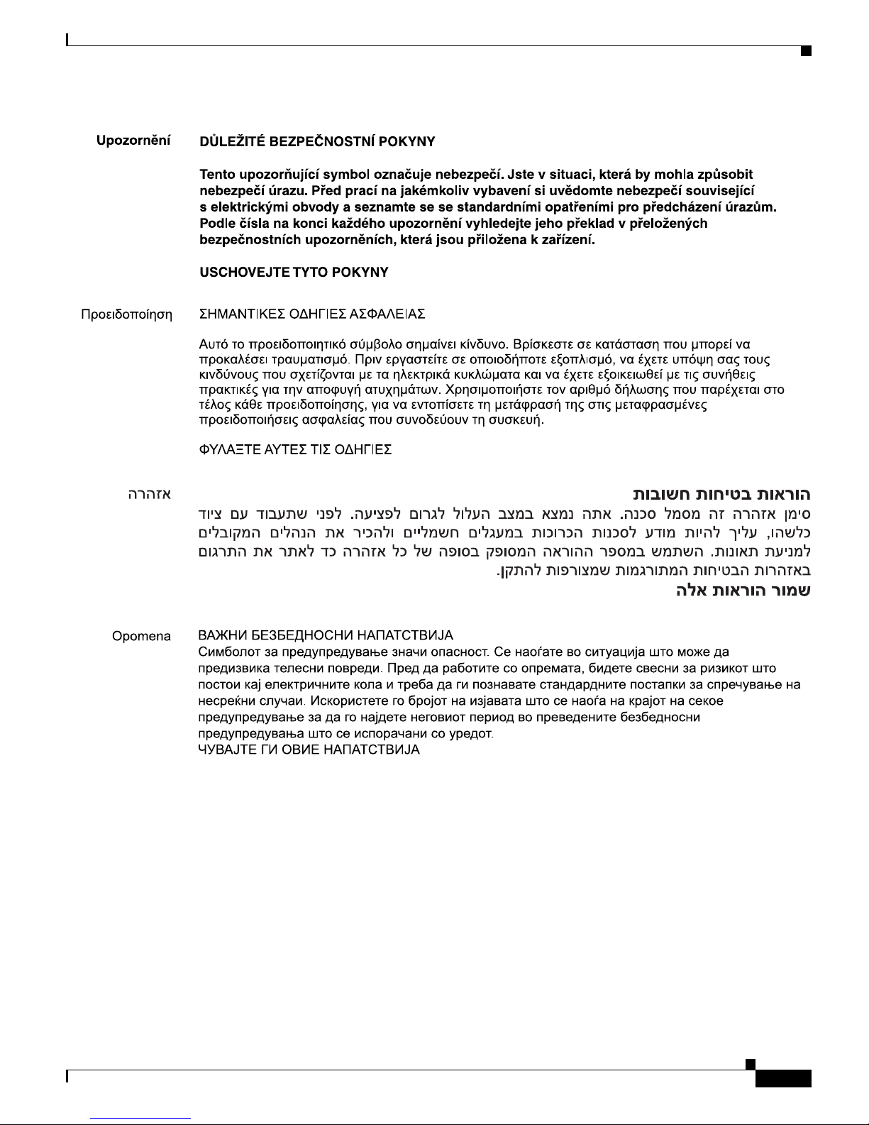
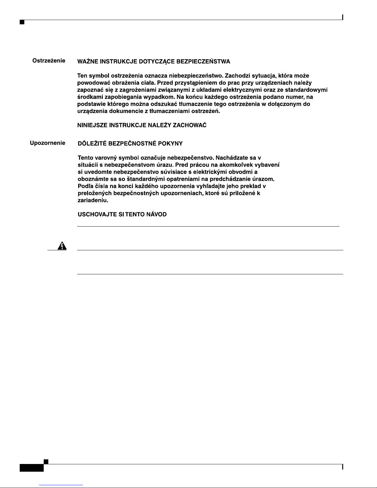
Warning
IMPORTANT SAFETY INSTRUCTIONS
This warning symbol means danger. You are in a situation that could cause bodily injury. Before you
work on any equipment, be aware of the hazards involved with electrical circuitry and be familiar
with standard practices for preventing accidents. Use the statement number provided at the end of
each warning to locate its translation in the translated safety warnings that accompanied this
device.
Statement 1071
SAVE THESE INSTRUCTIONS
Waarschuwing
BELANGRIJKE VEILIGHEIDSINSTRUCTIES
Dit waarschuwingssymbool betekent gevaar
. U verkeert in een situatie die lichamelijk letsel kan
veroorzaken. Voordat u aan enige apparatuur gaat werken, dient u zich bewust te zijn van de bij
elektrische schakelingen betrokken risico's en dient u op de hoogte te zijn van de standaard
praktijken om ongelukken te voorkomen. Gebruik het nummer van de verklaring onderaan de
waarschuwing als u een vertaling van de waarschuwing die bij het apparaat wordt geleverd, wilt
raadplegen.
BEWAAR DEZE INSTRUCTIES
Varoitus
TÄRKEITÄ TURVALLISUUSOHJEITA
Tämä varoitusmerkki merkitsee vaaraa. Tilanne voi aiheuttaa ruumiillisia vammoja. Ennen kuin
käsi
ttelet laitteistoa, huomioi sähköpiirien käsittelemiseen liittyvät riskit ja tutustu
onnettomuuksien yleisiin ehkäisytapoihin. Turvallisuusvaroitusten käännökset löytyvät laitteen
mukana toimitettujen käännettyjen turvallisuusvaroitusten joukosta varoitusten lopussa näkyvien
lausuntonumeroiden avulla.
SÄILYTÄ NÄMÄ OHJEET
Attention
IMPORTANTES INFORMATIONS DE SÉCURITÉ
Ce symbole d'avertissement indique un danger. V
ous vous trouvez dans une situation pouvant
entraîner des blessures ou des dommages corporels. Avant de travailler sur un équipement, soyez
conscient des dangers liés aux circuits électriques et familiarisez-vous avec les procédures
couramment utilisées pour éviter les accidents. Pour prendre connaissance des traductions des
avertissements figurant dans les consignes de sécurité traduites qui accompagnent cet appareil,
référez-vous au numéro de l'instruction situé à la fin de chaque avertissement.
CONSERVEZ CES INFORMATIONS
Page 12

vi
Cisco 7301 Installation and Configuration Guide
OL-5418-07
Preface
Document Organization
Warnung
WICHTIGE SICHERHEITSHINWEISE
Dieses Warnsymbol bedeutet Gefahr. Sie befinden sich i
n einer Situation, die zu Verletzungen führen
kann. Machen Sie sich vor der Arbeit mit Geräten mit den Gefahren elektrischer Schaltungen und
den üblichen Verfahren zur Vorbeugung vor Unfällen vertraut. Suchen Sie mit der am Ende jeder
Warnung angegebenen Anweisungsnummer nach der jeweiligen Übersetzung in den übersetzten
Sicherheitshinweisen, die zusammen mit diesem Gerät ausgeliefert wurden.
BEWAHREN SIE DIESE HINWEISE GUT AUF.
Avvertenza
IMPORTANTI ISTRUZIONI SULLA SICUREZZA
Questo simbolo di avvertenza indica un
pericolo. La situazione potrebbe causare infortuni alle
persone. Prima di intervenire su qualsiasi apparecchiatura, occorre essere al corrente dei pericoli
relativi ai circuiti elettrici e conoscere le procedure standard per la prevenzione di incidenti.
Utilizzare il numero di istruzione presente alla fine di ciascuna avvertenza per individuare le
traduzioni delle avvertenze riportate in questo documento.
CONSERVARE QUESTE ISTRUZIONI
Advarsel
VIKTIGE SIKKERHETSINSTRUKSJONER
Dette advarselssymbolet betyr fare. Du er i en situasjon som kan føre til skade på person. Før du
begynner å
arbeide med noe av utstyret, må du være oppmerksom på farene forbundet med
elektriske kretser, og kjenne til standardprosedyrer for å forhindre ulykker. Bruk nummeret i slutten
av hver advarsel for å finne oversettelsen i de oversatte sikkerhetsadvarslene som fulgte med denne
enheten.
TA VARE PÅ DISSE INSTRUKSJONENE
Aviso
INSTRUÇÕES IMPORTANTES DE SEGURANÇA
Este símbolo de aviso significa perigo. Você está em
uma situação que poderá ser causadora de
lesões corporais. Antes de iniciar a utilização de qualquer equipamento, tenha conhecimento dos
perigos envolvidos no manuseio de circuitos elétricos e familiarize-se com as práticas habituais de
prevenção de acidentes. Utilize o número da instrução fornecido ao final de cada aviso para
localizar sua tradução nos avisos de segurança traduzidos que acompanham este dispositivo.
GUARDE ESTAS INSTRUÇÕES
¡Advertencia!
INSTRUCCIONES IMPORTANTES DE SEGURIDAD
Este símbolo de aviso indica peligro
. Existe riesgo para su integridad física. Antes de manipular
cualquier equipo, considere los riesgos de la corriente eléctrica y familiarícese con los
procedimientos estándar de prevención de accidentes. Al final de cada advertencia encontrará el
número que le ayudará a encontrar el texto traducido en el apartado de traducciones que acompaña
a este dispositivo.
GUARDE ESTAS INSTRUCCIONES
Page 13

vii
Cisco 7301 Installation and Configuration Guide
OL-5418-07
Preface
Document Organization
Varning!
VIKTIGA SÄKERHETSANVISNINGAR
Denna varningssignal signalerar fara. Du befinner di
g i en situation som kan leda till personskada.
Innan du utför arbete på någon utrustning måste du vara medveten om farorna med elkretsar och
känna till vanliga förfaranden för att förebygga olyckor. Använd det nummer som finns i slutet av
varje varning för att hitta dess översättning i de översatta säkerhetsvarningar som medföljer denna
anordning.
SPARA DESSA ANVISNINGAR
Page 14

viii
Cisco 7301 Installation and Configuration Guide
OL-5418-07
Preface
Document Organization
Aviso
INSTRUÇÕES IMPORTANTES DE SEGURANÇA
Este símbolo de aviso significa perigo. Você se enc
ontra em uma situação em que há risco de lesões
corporais. Antes de trabalhar com qualquer equipamento, esteja ciente dos riscos que envolvem os
circuitos elétricos e familiarize-se com as práticas padrão de prevenção de acidentes. Use o
número da declaração fornecido ao final de cada aviso para localizar sua tradução nos avisos de
segurança traduzidos que acompanham o dispositivo.
GUARDE ESTAS INSTRUÇÕES
Advarsel
VIGTIGE SIKKERHEDSANVISNINGER
Dette advarselssymbol betyder fare. Du befinder dig i en situation med risiko for
l
egemesbeskadigelse. Før du begynder arbejde på udstyr, skal du være opmærksom på de
involverede risici, der er ved elektriske kredsløb, og du skal sætte dig ind i standardprocedurer til
undgåelse af ulykker. Brug erklæringsnummeret efter hver advarsel for at finde oversættelsen i de
oversatte advarsler, der fulgte med denne enhed.
GEM DISSE ANVISNINGER
Page 15
ix
Cisco 7301 Installation and Configuration Guide
OL-5418-07
Preface
Document Organization
Page 16
x
Cisco 7301 Installation and Configuration Guide
OL-5418-07
Preface
Related Documentation
Warning
Ultimate disposal of this product should be handled according to all national laws and regulations.
To see translations of the warnings that appear in this publication, refer to the Regulatory Compliance
and Safety Information document that accompanied the equipment.
Related Documentation
Your Cisco 7301 router and the Cisco IOS software running on it contain extensive features and
functionality, which are documented in the following resources:
• Cisco Documentation DVD package (See the “Obtaining Documentation and Submitting a Service
Request” section on page xi.)
• Cisco.com (See the “Obtaining Documentation and Submitting a Service Request” section on
page xi.)
• Cisco IOS software documentation contains Cisco IOS software configuration information and
support. See the modular configuration and modular command reference publications in the set that
corresponds to the software release installed on your Cisco hardware.
• All documentation related to the Cisco 7301 router, is listed in the online Cisco 7301 Router
Documentation Roadmap. I
nformation in this master index includes troubleshooting tools and
documentation, regulatory compliance and safety information, and installation and replacement
information.
Some of the Cisco 7301 documentation that is listed on the C
isco 7301 Router Documentation
Roadmap i
ncludes:
Page 17

xi
Cisco 7301 Installation and Configuration Guide
OL-5418-07
Preface
Obtaining Documentation and Submitting a Service Request
–
The Cisco 7301 Installation and Configuration Guide contains complete installation and startup
configuration information.
–
The Cisco 7301Router Quick Start Guide contains installation and configuration information
and is online. It contains quick reference information about chassis or parts installation.
–
The Cisco 7301 Troubleshooting document contains information to help you troubleshoot
problems with the Cisco 7301 router.
–
Cisco 7301 Router Troubleshooting and Configuration Notes
–
Regulatory Compliance and Safety Information for the Cisco 7301 Router This document
provides international agency compliance, safety, and statutory information for wide-area
network (WAN) interfaces for the Cisco 7301 router. It also contains information previously
found in the Site Preparation and Safety Guide.
–
Port adapter and service adapter documentation. See the documentation guide that ships with
the port adapter or service adapter for the customer order number.
• To check the minimum software requirements of Cisco IOS software with the hardware installed on
your router, Cisco maintains the Software Advisor tool on Cisco.com. This tool does not verify
whether modules within a system are compatible, but it does provide the minimum IOS requirements
for individual hardware modules or components.
To access Software Advisor, click Log
In at Cisco.com and go to Support, Tools and Resources.
Note Access to this tool is limited to users with Cisco.com login accounts.
Obtaining Documentation and Submitting a Service Request
For information on obtaining documentation, submitting a service request, and gathering additional
information, see the monthly What’s New in Cisco Product Documentation,
which also lists all new and
revised Cisco technical documentation, at:
http://www.cisco.com/en/US/docs/general/whatsnew/whatsnew.html
Subscribe to the Wh
at’s New in Cisco Product Documentation as a Really Simple Syndication (RSS) feed
and set content to be delivered directly to your desktop using a reader application. The RSS feeds are a free
service and Cisco currently supports RSS Ve r si o n 2.0.
Page 18

xii
Cisco 7301 Installation and Configuration Guide
OL-5418-07
Preface
Obtaining Documentation and Submitting a Service Request
Page 19

CHAPTER
1-1
Cisco 7301 Installation and Configuration Guide
OL-5418-07
1
Cisco 7301 Overview
The Cisco 7301 router provides application-specific features for broadband subscriber aggregation and
network application services with high processing performance.
This chapter provides a quick hardware and features overview and options installation instructions for
t
he Cisco 7301 router. For functional information see Chapter 3, “Starting and Configuring the Router,”
the “Functional Overview” section on page 3-1. For system specifications and port and cabling
specifications, see Appendix A, “Specifications.”
This chapter includes the following sections:
• Cisco 7301 Features, page 1-2
• Cisco 7301 Hardware Overview, page 1-3
• Checking the Shipping Container Contents, page 1-7
• Cisco 7301 Router Installation Checklist, page 1-8
• About the SFP GBIC Module, page 1-9
• Installing the SFP GBIC Module, page 1-11
Warning
This warning means danger. You are in a situation that could cause bodily injury. Before you work on
any equipment, be aware of the hazards involved with electrical circuitry and be familiar with the
standard practices for preventing accidents. To see translations of the warnings that appear in this
publication, refer to the CRegulatory Compliance and Safety Information for the Cisco 7301 Router
publication that accompanied this device
. Statement 1071
Warning
Before you install, operate, or service the system, read the “Preparing to Install the Cisco 7301 Router”
section on page 2-1 and the R
egulatory Compliance and Safety Information for the Cisco 7301 Router
publication. These documents provide important safety inf
ormation you should know before working
with the system.
Statement 200
Page 20

1-2
Cisco 7301 Installation and Configuration Guide
OL-5418-07
Chapter 1 Cisco 7301 Overview
Cisco 7301 Features
Cisco 7301 Features
Each Cisco 7301 router consists of the following features:
• Small form-factor—One rack-unit (RU) high with stacking capability:
1.73 in. x 17.3 in. x 13.87 in. (4.39 cm x 43.9 cm x 35.23 cm). The weight is approximately 10.5 lbs
(4
.76 kg).
• Three native Gigabit Ethernet interfaces—six ports:
–
Three optical fiber Gigabit Ethernet (1000 Mbps) ports that use a small form factor pluggable
(SFP) Gigabit Interface Converter (GBIC) modules with LC connectors
–
Three Gigabit Ethernet (10/100/1000 Mbps) ports with RJ-45 connectors (any three ports are
available at any one time)
• Both 25-MHz and 50-MHz port adapter operation
• A 64- or 128-MB CompactFlash Disk
• SFP GBIC modules: Three Gigabit Ethernet SX, LH, ZX module options, 1000BASE-T SFP
(copper) module, and several coarse wavelength-division multiplexing CWDM SFP modules
• Power supplies:
–
Single or dual AC power supplies
–
Single 24V DC power supply
–
Dual 48V DC power supply
• BCM 1250 integrated dual processors that operates at an internal clock speed of 700 MHz
• 512-KB Boot ROM
• 32-MB Boot Flash
• Three SDRAM memory options: 256 MB, 512 MB, and 1 GB
• Auxiliary port
• Console port
• Online insertion and removal (OIR)—Allows you to add, replace, or remove port adapters with
minimal interruption of the system
• Environmental monitoring and reporting functions—Allow you to maintain normal system
operation by resolving adverse environmental conditions prior to loss of operation
• Downloadable software—Allows you to load new images into Flash memory remotely, without
having to physically access the router, for fast, reliable upgrades
• Front-to-back airflow—Allows you to mount the router from either front or back into 19-inch
two-post racks and 21–23-inch four-post racks
Page 21
1-3
Cisco 7301 Installation and Configuration Guide
OL-5418-07
Chapter 1 Cisco 7301 Overview
Cisco 7301 Hardware Overview
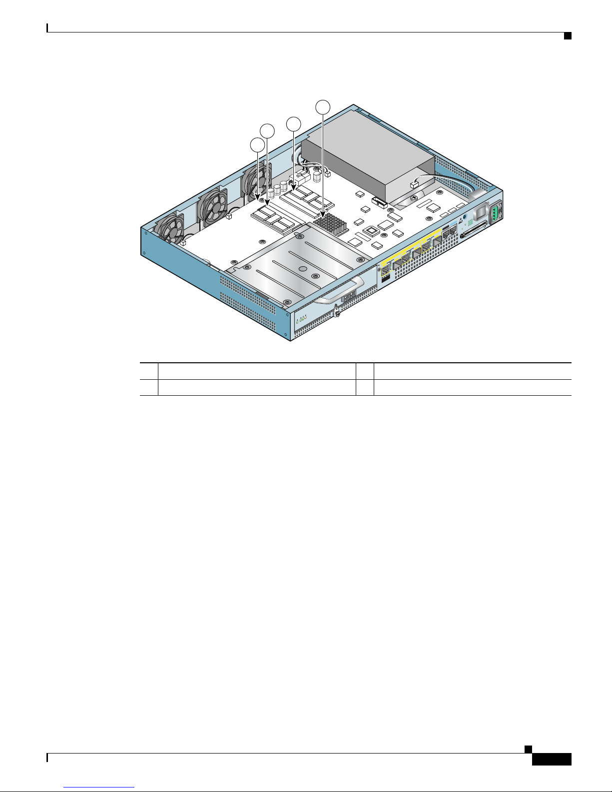
Figure 1-1 Cisco 7301 Router—Interior View
Temperature sensor 1 (U62) is on the underneath side of the board.
Cisco 7301 Hardware Overview
This section provides you with an overview of the hardware including LEDs, front and rear views, and
interior part identification.
1 Temperature sensor 2 (U5) 3 SODIMM 2 (J2)
2 SODIMM 1 (J1) 4 BCM 1250 Processor (U31)
80957
ENABLED
RX CELLS
RX CARRIER
RX ALARM
ATM
ALARM
RJ45 EN
LINK
TX
RX
GBIC
GIGABIT ETHERNET 0/2
RJ45 EN
LINK
TX RX
GBIC
GIGABIT ETHERNET 0/0
RJ45 EN
LINK
TX
RX
GBIC
GIGABIT ETHERNET 0/1
CISCO 7301
SLOT 1
CONSOLE
AUX
COMPACT
FLASH
STATUS
100-240V, 2 A, 5 0/60 Hz
24V
=
9A, 48 - 60V
=
5A
BA
4
2
1
3
Page 22
1-4
Cisco 7301 Installation and Configuration Guide
OL-5418-07
Chapter 1 Cisco 7301 Overview
Cisco 7301 Hardware Overview
Front View
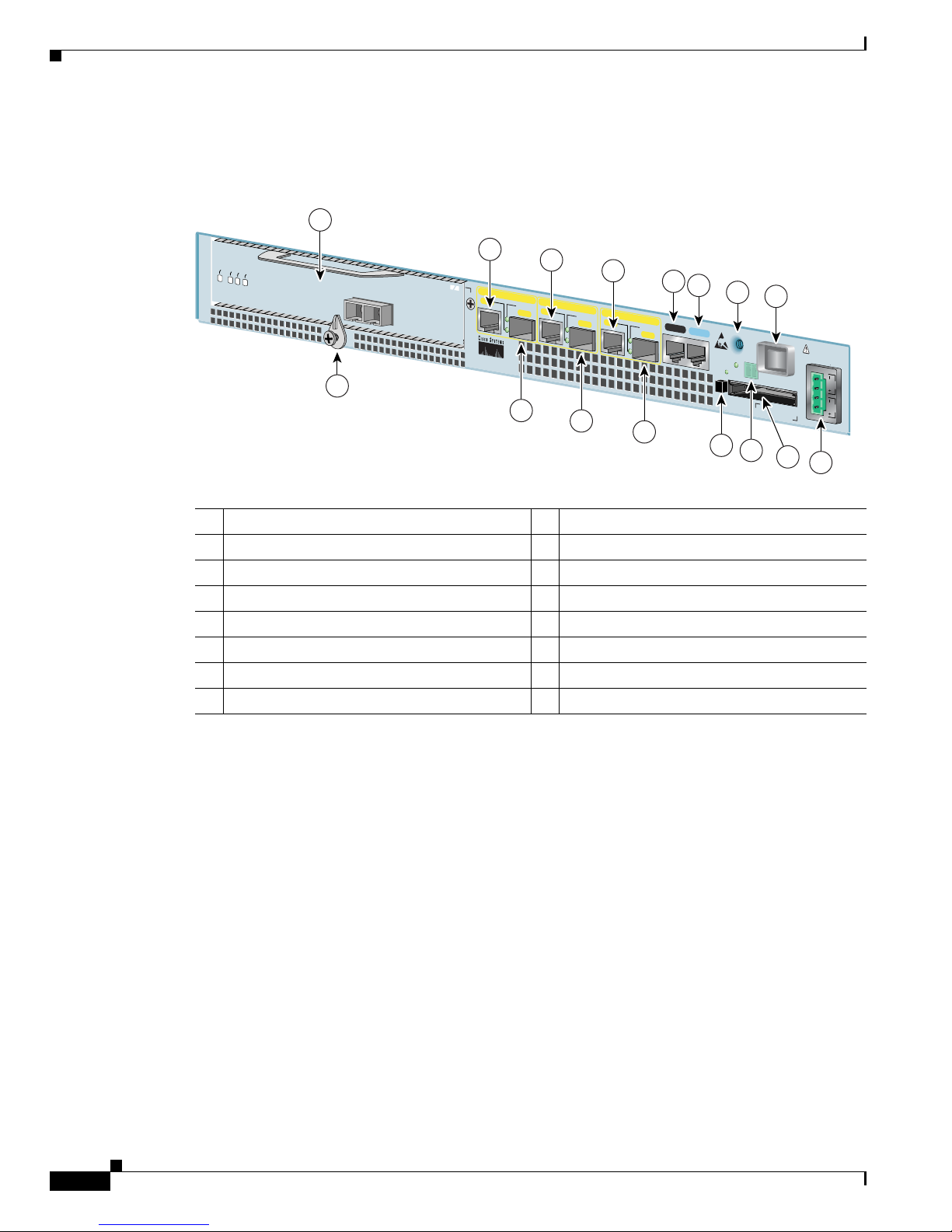
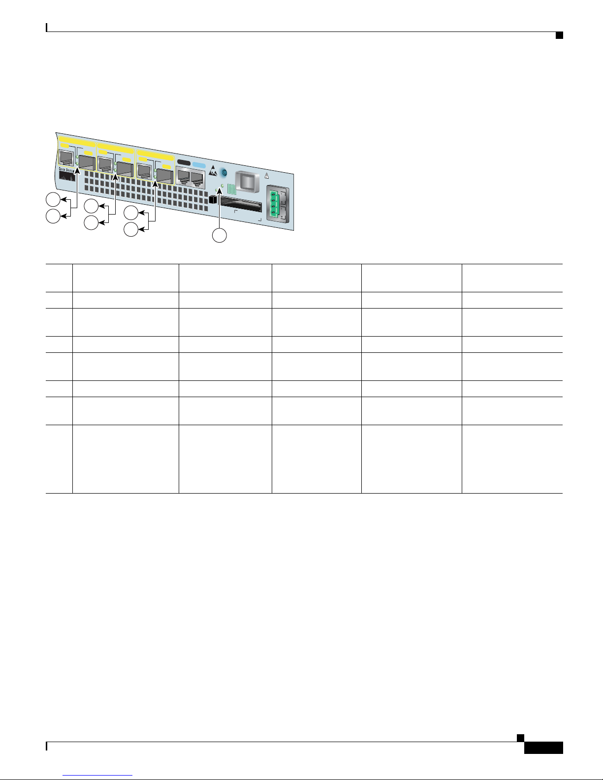
Figure 1-2 Cisco 7301 Router—Front View
1 Port adapter slot (with installed port adapter) 9 Auxiliary port
2 Port adapter latch 10 Console port
3 Gigabit Ethernet 0/0—RJ-45 port 11 CompactFlash Disk ejector button
4 Gigabit Ethernet 0/0—SFP GBIC port 12 Ground for ESD wrist strap with banana jack
5 Gigabit Ethernet 0/1—RJ-45 port 13 Alarm port
6 Gigabit Ethernet 0/1—SFP GBIC port 14 Power switch
7 Gigabit Ethernet 0/2—RJ-45 port 15 CompactFlash Disk slot
8 Gigabit Ethernet 0/2—SFP GBIC port 16 Power connector
ALARM
RJ45 EN
LINK
TX RX
GBIC
GIGABIT ETHERNET 0/2
RJ45 EN
LINK
TX RX
GBIC
GIGABIT ETHERNET 0/0
RJ45 EN
LINK
TX RX
GBIC
GIGABIT ETHERNET 0/1
CISCO 7301
SLOT 1
CONSOLEAUX
COMPACT
FLASH
STATUS
100-240V, 2A, 50/60 Hz
24V
=
9A, 48 - 60V
=
5A
ENABLED
RX CELLS
RX CARRIER
RX ALARM
ATM
80265
12
1
3
5
7
14
2
4
6
8
15
11
13
9
10
BA
16
Page 23
1-5
Cisco 7301 Installation and Configuration Guide
OL-5418-07
Chapter 1 Cisco 7301 Overview
Cisco 7301 Hardware Overview
LEDs
Figure 1-3 Cisco 7301 Router—LEDs
No. LED Label LED Color Status
LED flashes when
th
ere is traffic
1 LINK (0/0) LINK (0/0) Green — Ye s
2 RJ-45 EN (0/0) RJ-45 enable (0/0) Green In the Power Up state,
the LED is on
No, remains
c
onstantly on
3 LINK (0/1) LINK (0/1) Green — Ye s
4 RJ-45 EN (0/1) RJ-45 enable (0/1) Green In the Power Up state,
the LED is on
No, remains
c
onstantly on
5 LINK (0/2) LINK (0/2) Green — Ye s
6 RJ-45 EN (0/2) RJ-45 enable (0/2) Green In the Power Up state,
the LED is on
No, remains
c
onstantly on
7 STATUS System status Amber while the
sy
stem boots
Green when the
sy
stem is
operational
—
In the Power Up state,
the LED is on
—
No, remains
c
onstantly on
80266
ALARM
RJ45 EN
LINK
TX RX
GBIC
GIGABIT ETHERNET 0/2
RJ45 EN
LINK
TX RX
GBIC
GIGABIT ETHER
NET 0/0
RJ45 EN
LINK
TX RX
GBIC
GIGABIT ETHERNET 0/1
CISCO 7301
CONSOLEAUX
COMPACT
FLASH
STATUS
100-240V, 2A, 50/60 Hz
24V
=
9A, 48 - 60V
=
5A
BA
1
2
3
4
5
6
7
Page 24
1-6
Cisco 7301 Installation and Configuration Guide
OL-5418-07
Chapter 1 Cisco 7301 Overview
Cisco 7301 Hardware Overview
Rear View
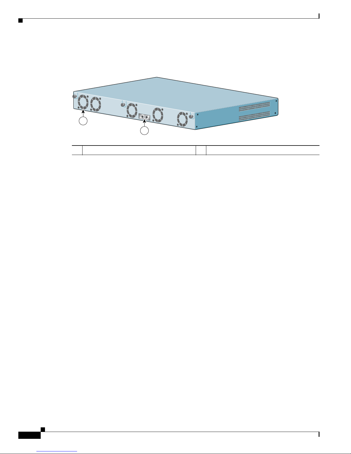
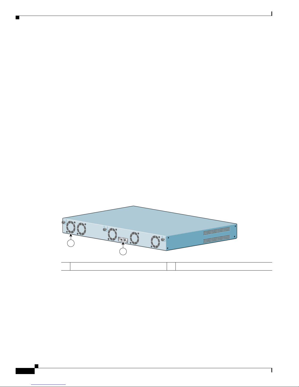
Figure 1-4 Cisco 7301—Rear View
Five internal fans draw cooling air into the chassis and across internal components to maintain an
acceptable operating temperature. (See Figure 1-4.) The five fans are located at the rear of the chassis as
is the chassis grounding connector that provide a chassis ground connection for ESD equipment or a
t
wo-hole grounding lug.
System Board
Internally, the system board contains the following components:
• Two SODIMM DDR-SDRAM memory modules that are available in three options: 128 MB,
256 MB, and 512 MB
• BCM 1250 processor system
• BCM 1250 integrated dual processor that operates at an internal clock speed of 700 MHz. The
BCM 1250 processor maintains and executes the system management functions for the Cisco 7301
ro
uter. The processor also performs some memory and environmental monitoring functions.
–
The BCM 1250 serves as the system controller. It interconnects the processor with the double
data rate synchronous dynamic random-access memory (DDR-SDRAM) controller, lightning
data transport (LDT) bus, and the three direct-interface Gigabit Ethernet interfaces, and the port
adapter PCI bus, which allows the port adapter access to DDR-SDRAM.
• Cache memory
The processor system has two levels of cache: primary and secondary cache that are internal to the
mi
croprocessor with secondary unified cache for data and instruction.
• Three Gigabit Ethernet interfaces: (six ports: three SFP GBIC [optical] and three RJ-45s [copper]).
Any three ports are available at the same time and are linked directly to the BCM 1250 system.
• A CompactFlash Disk for storing the default Cisco IOS software image.
• Auxiliary port with full data terminal equipment (DTE) functionality.
• Boot ROM for storing sufficient code for booting the Cisco IOS software.
• Flash memory for storing the boot helper (boot loader) image.
1 Fan 2 Grounding connector
80267
1
2
Page 25

1-7
Cisco 7301 Installation and Configuration Guide
OL-5418-07
Chapter 1 Cisco 7301 Overview
Checking the Shipping Container Contents
• NVRAM for storing the system configuration and environmental monitoring logs. NVRAM uses
lithium batteries to maintain its contents when disconnected from power.
• Two environmental sensors for monitoring the internal temperature of the chassis.
System Management Functions
The Cisco 7301 processor system performs the following system management functions:
• Sending and receiving routing protocol updates
• Managing tables, caches, and buffers
• Monitoring interface and environmental status
• Providing Simple Network Management Protocol (SNMP) management through the console and
Telnet interface
• Accounting for and switching of data traffic
• Booting and reloading images
• Managing the port adapter (including recognition and initialization during online insertion and
removal)
The Cisco 7301 router supports multiprotocol, multimedia routing and bridging with a wide variety of
pr
otocols and port adapters.
Checking the Shipping Container Contents
Use the Cisco 7301 components list to check the contents of the Cisco 7301 router shipping container.
Do not discard the shipping container. You need the container if you move or ship the Cisco 7301 router
in the future.
Page 26

1-8
Cisco 7301 Installation and Configuration Guide
OL-5418-07
Chapter 1 Cisco 7301 Overview
Cisco 7301 Router Installation Checklist
Note We no longer ship the entire router documentation set automatically with each system. You must
specifically order the documentation as part of the sales order. If you ordered documentation and did not
receive it, we will ship the documents to you within 24 hours. To order documents, contact a customer
service representative.
Cisco 7301 Router Installation Checklist
To assist you with your installation and to provide a historical record of what was done by whom,
photocopy the Cisco 7301 Router Installation Checklist, Table 1-2 on page 1-9. Indicate when each
procedure or verification is completed. When the checklist is completed, place it in your site log along
wi
th the other records for your new router.
Information on replacing internal field-replaceable units (FRUs) is found in Ch
apter 4, “Installing and
Removing Field-Replaceable Units.”
Ta b l e 1-1 Cisco 7 301 Components Li st
Component Description Received
Chassis Cisco 7301 chassis configured with a single or dual AC or DC power supply and port
ad
apter filler plate.
Accessories:
• Rack-mount and
cable-management kit
• AC power
cable-retention clip
• Power cables
• Documentation
The following accessories might arrive in separate shipping containers:
Two rack-mount brackets, one cable-management bracket, four 12-24 x 0.5-in.
sc
rews to secure the rack-mount brackets to the chassis, four 8-18 x .37-in. screws
to secure the rack-mount brackets to a 19-inch rack, four 8 x .375-in. screws to
secure the rack-mount brackets to a 21–23-inch rack, and one M4 x 20-mm screw to
attach the cable-management bracket to the rack-mount bracket
If a single AC power supply is ordered, an AC power cable-retention clip ships
An AC power cable, if an AC power supply was ordered
If ordered, router hardware and software documentation and the Cisco
Documentation CD-ROM package
1
1. Titles and quantities of documents will vary. You must order the type and quantity of documentation sets when you order the hardware.
Optional Equipment
Examples: Port adapter, SFP GBIC modules , network interface cables, transceivers,
s
pecial connectors and so on
Page 27

1-9
Cisco 7301 Installation and Configuration Guide
OL-5418-07
Chapter 1 Cisco 7301 Overview
About the SFP GBIC Module
About the SFP GBIC Module
You may have ordered a SFP (small form-factor pluggable) Gigabit Interface Converter (GBIC) module
with your Cisco 7301 router. You must install the SFP GBIC module. It is shipped separately to prevent
damage during shipment. After reading this section, use the installation instructions in the “Installing
the SFP GBIC Module” section on page 1-11 the to install the SFP GBIC modules.
For ease of installation, insert the SFP GBICmodule in th
e router while it is powered down and before
placing it in a rack.
The SFP GBIC port is a 1000-Mbps optical interface in the form of an LC-type duplex port that supports
I
EEE 802.3z interfaces compliant with the 1000BASEX standard. Gigabit Ethernet SFP GBIC models
GLC-SX-MM, GLC-LH-SM, and GLC-ZX-SM are supported in the Cisco 7301 router, as well as the
Cisco 1
000BASE-T SFP. In addition, a variety of Coarse Wave Division Multiplexing (CWDM) SFPs
are supportedon the Cisco 7301. The cabling information is the same for all optical SFPs.
Ta b l e 1-2 Cisco 7301 Router Installation Checklist
Tas k
Verified
By Date
Date router received
Router and all accessories unpacked
Types and numbers of interfaces verified
Safety recommendations and guidelines reviewed
Installation Checklist copied
Site log established and background information entered
Site power voltages verified
Site environmental specifications verified
Required passwords, IP addresses, device names, and so on, available
Required tools available
Network connection equipment available
Router mounted in rack (optional)
Cable-management bracket installed (optional but recommended)
AC power cable(s) connected to AC source(s) and router; cable-retention clip secured
DC power cable(s) connected to DC source(s) and router
Network interface cables and devices connected
ASCII terminal attached to console port
Console port set for 9600 baud, 8 data bits, no parity, and 1 stop bits (9600 8N1)
System power turned on
System boot complete (STATUS LED is on)
I/O ports and port adapter are operational (see Fi
gure 1-3 for specific LED information)
Correct hardware configuration displayed after system banner appears
Page 28
1-10
Cisco 7301 Installation and Configuration Guide
OL-5418-07
Chapter 1 Cisco 7301 Overview
About the SFP GBIC Module
Also see “SFP GBIC Module Configurations” section on page A-4, the Gigabit Interface Converter
(GBIC) and Small Form-Factor Pluggable(SFP) GBIC Installation Inforamtion and Specifications, and
the Coarse Wavelength-Division Multiplexing SFP Compatability Matrix.
For optical connection cleaning information, see the In
spection and Cleaning Procedures for Fiber-Optic
Connections do
cument.
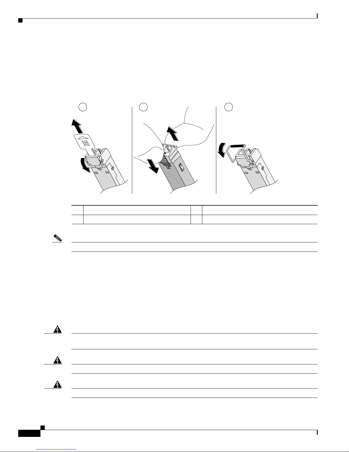
Figure 1-5 Types of SFP GBIC Module Latches
Note The SFP GBIC module must be installed before you connect the cables to it.
• The SPF GBIC module has three types of latches, which are also the removal mechanism. See
Figure 1-5.
There is no correlation of the type of latch to the model (such as SX or LH) or
technology type (such as Gigabit Ethernet) of SFP modules.
Always read the label on the SFP GBIC
module to determine the technology type, and model.
• You can install and remove Gigabit Ethernet SFP GBIC modules with power on to the system.
• Disconnect all cables before removing or installing a Gigabit Ethernet SFP module. We strongly
recommend that you do not install or remove the SFP GBIC with optical fiber cables attached to it.
• SFP GBIC modules are keyed to prevent incorrect insertion.
Warning
Invisible laser radiation may be emitted from disconnected fibers or connectors. Do not stare into
beams or view directly with optical instruments.
Statement 1051
Warning
Class 1 laser product.
Statement 1008
Warning
Class 1 LED product.
Statement 1027
1 Sliding latch 3 Swing latch
2 Swing and slide latch
80755
1 2 3
Page 29
1-11
Cisco 7301 Installation and Configuration Guide
OL-5418-07
Chapter 1 Cisco 7301 Overview
Installing the SFP GBIC Module
Warning
During this procedure, wear grounding wrist straps to avoid ESD damage to the card. Do not directly
touch the backplane with your hand or any metal tool, or you could shock yourself.
Statement 94
Installing the SFP GBIC Module
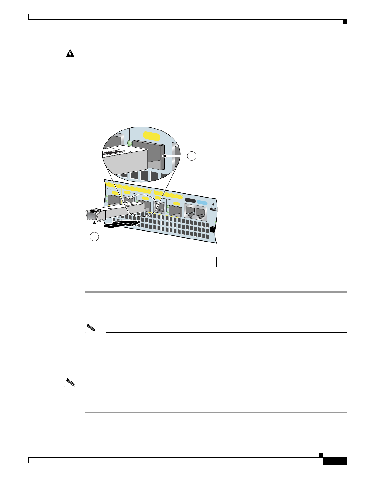
Figure 1-6 Inserting a SFP GBIC Module into the Cisco 7301 Gigabit Ethernet Port 0/1
Use the following procedure to install a SFP GBICmodule:
Step 1 Attach an ESD-preventive wrist strap between you and an unpainted chassis surface.
Step 2 Locate the label on the SFP GBIC module and turn the SFP GBIC module so the label is on top and the
alignment groove is down.
Note The SFP GBIC module is keyed so that it cannot be inserted incorrectly.
Step 3 Insert the SFP GBIC module into SFP GBIC port 0/1, 0/2, or 0/3. The SFP GBIC module snaps into place
when you have completely and properly inserted it.
Step 4 Repeat Step 2 if you are inserting a second or third SFP GBIC module.
Note Do not remove the plug from the SFP GBIC optical bores until you are ready to install the network
interface optical fiber cable. Save the plug for future use.
This completes the SFP GBIC module installation procedure.
1 SFP GBIC port 0/1 2 SFP GBIC module
RJ45 EN
LINK
TX RX
GBIC
GIGABIT ETHERNET 0/2
ETHERNET 0/0
LINK
TX RX
GBIC
RJ45 EN
LINK
TXRX
GBIC
GIGABIT ETHERNET 0/1
SERIES
CONSOLE
AUX
COMPAC
FLASH
80269
2
TX RX
TX RX
GBIC
1
Page 30

1-12
Cisco 7301 Installation and Configuration Guide
OL-5418-07
Chapter 1 Cisco 7301 Overview
Installing the SFP GBIC Module
For information on removing and installing other options, see Chapter 4, “Installing and Removing
Field-Replaceable Units.”
For rack-mounting and cabling procedures, see Ch
apter 2, “Rack-Mounting, Tabletop Installation, and
Cabling.”
Page 31

CHAPTER
2-1
Cisco 7301 Installation and Configuration Guide
OL-5418-07
2
Rack-Mounting, Tabletop Installation, and
Cabling
This chapter explains how to install a Cisco 7301 router in a rack in a general tabletop or workbench
installation, how to attach cables, and how to power on the router.
This chapter contains the following sections:
• Preparing to Install the Cisco 7301 Router, page 2-1
• Installing the Router, page 2-4
• Attaching a Chassis Ground Connection, page 2-12
• Connecting Port Adapter Cables, page 2-14
• Connecting I/O Cables, page 2-14
• Attaching the Alarm Port Cable, page 2-21
• Using the Cable-Management Bracket, page 2-21
• Connecting Power, page 2-22
The Cisco 7301 router operates as either a tabletop or a rack-mounted unit. A rack-mount kit is standard
eq
uipment included with the Cisco 7301 router when it is shipped from the factory. The kit provides the
hardware needed to mount the router in a standard four-post 19-inch equipment rack or a two-post rack
or a 21–23-inch equipment rack.
If you are not rack-mounting your Cisco 7301 router, place it on a sturdy tabletop or platform.
Preparing to Install the Cisco 7301 Router
Before installing your Cisco 7301 router, you should consider the power and cabling requirements that
must be in place at your installation site, the equipment you need to install the router, and the
environmental conditions your installation site must meet to maintain normal operation. This section
guides you through the process of preparing for your router installation and the installation in a rack.
This section contains the following topics:
• Tools and Parts Required, page 2-2
• Electrical Equipment Guidelines, page 2-3
• Preventing Electrostatic Discharge Damage, page 2-3
• Site Requirement Guidelines, page 2-4
Page 32

2-2
Cisco 7301 Installation and Configuration Guide
OL-5418-07
Chapter 2 Rack-Mounting, Tabletop Installation, and Cabling
Preparing to Install the Cisco 7301 Router
Figure 2-1 Dimensions of Cisco 7301 Router
Table 2-1 provides dimensions and weight information.
Tools and Parts Required
Your Cisco 7301 chassis is fully assembled at the factory; no assembly is required. However, you need
the following tools and equipment to install the chassis and the rack-mount and cable-management kit:
• Number 2 Phillips screwdriver
• A 3/16-inch flat-blade screwdriver
• Tape measure (optional)
• Level (optional)
• Grounding lug and wires:
–
A grounding lug with two number-10 screw holes with a 0.63-inch (16.002-mm) spacing
between them
–
A wire receptacle large enough to accept a 6-AWG multistrand, copper wire
–
Two Phillips machine screws with locking washers—M5 (metric), 0.031-inch (.08-mm) pitch,
0.315-inch (8-mm) length
–
A crimping tool to fit the grounding lug wire receptacle
1 13.87 in. 3 12.3 in.
2 17.3 in.
1
50537
2
3
Ta b l e 2-1 Cisco 7301 Router Dimensions and Weight
Cisco 7301
Dimensions 1.73 in. x 17.3 in. x 13.87 in. (4.39 cm x 43.9 cm x 35.23 cm)
Weight Chassis fully configured with a port adapter ~ 10.5 lb (4.76 kg)
Page 33

2-3
Cisco 7301 Installation and Configuration Guide
OL-5418-07
Chapter 2 Rack-Mounting, Tabletop Installation, and Cabling
Preparing to Install the Cisco 7301 Router
–
One grounding wire—6-AWG, 0.162-inch (4.115-mm) diameter, with approximately
0.108-inch (2.743-mm) insulation, for a total wire diameter of approximately 0.27 inches
(6.858 mm). The wire length depends on your router location and site environment.
The rack-mount and cable-management kit includes the following parts:
• Two rack-mount brackets for mounting the chassis in the rack
• One cable-management bracket
• One AC power cable-retention clip (if you ordered a single AC power supply)
• Four 12-24 x 0.5-in. screws to secure the rack-mount brackets to the chassis
• Four 8-18 x .37-in. screws to secure the rack-mount brackets to a 19-inch rack
• Four 8 x .375-in. screws to secure the rack-mount brackets to a 21–23-inch rack
• One M4 x 20-mm screw to attach the cable-management bracket to the rack-mount bracket
In addition, you might need the following external equipment:
• Data service unit (DSU) to connect each serial port to an external network
• T1 channel service unit/data service unit (CSU/DSU) that converts the High-Level Data Link
Control (HDLC) synchronous serial data stream into a T1 data stream with the correct framing and
ones density to connect a serial port to a T1 network. (Some telephone systems require a minimum
number of 1 bits per time unit in a data stream, called ones density.) Several T1 CSU/DSU devices
are available as additional equipment, and most provide a V.35, EIA/TIA-449, or EIA-530 electrical
interface.
• Ethernet transceiver
• Token Ring multistation access unit (MSAU)
• ESD-preventative wrist strap
• Power cord
• Appropriate cables to connect the router to the console and auxiliary ports
Electrical Equipment Guidelines
The port adapter is designed to be removed and replaced while the system is operating without
presenting an electrical hazard or damage to the system.
Preventing Electrostatic Discharge Damage
Electrostatic discharge (ESD) damage, which occurs when electronic cards or components are
improperly handled, can result in complete or intermittent system failures. Each port adapter consists of
a printed circuit board that is fixed in a metal carrier. Electromagnetic interference (EMI) shielding,
connectors, and a handle are integral components of the carrier. Although the carrier helps protect the
boards, use an antistatic strap whenever handling the port adapter. Handle the carriers by the handle and
the carrier edges only; never touch the boards or connector pins.
Page 34

2-4
Cisco 7301 Installation and Configuration Guide
OL-5418-07
Chapter 2 Rack-Mounting, Tabletop Installation, and Cabling
Installing the Router
Site Requirement Guidelines
Warning
Before you install, operate, or service the system, read the “Site Preparation and Safety Information”
section of the Cisco 7301 Series Internet Routers Regulatory Compliance and Safety Information
document. This section contains important safety information you should know before working with
the system.
Statement 200
The environmental monitoring functionality in the Cisco 7301 router protects the system and
components from potential damage from overvoltage and overtemperature conditions. To ensure normal
operation and avoid unnecessary maintenance, plan your site configuration and prepare your site before
installation. After installation, make sure the site maintains an ambient temperature of 32•F through F through
104•F (0•C through 40•C), and keep the area around the chassis as free from dust as is practical. F (0•C through 40•C), and keep the area around the chassis as free from dust as is practical.
Planning a proper location for the Cisco 7301 router and the layout of your equipment rack or wiring
cl
oset is essential for successful system operation. Equipment placed too close together or inadequately
ventilated can cause system overtemperature conditions. In addition, chassis panels made inaccessible
by poor equipment placement can make system maintenance difficult. Following are precautions that can
help avoid problems during installation and ongoing operation.
Figure 2-2 Airflow Through the Chassis
When you plan the location and layout of your equipment rack or wiring closet, you need to consider
how air flows through your router. The Cisco 7301 router draws cooling air in through the intake vents
on the front of the chassis and moves the air across the internal components and out the exhaust vents
on the rear of the chassis. Figure 2-2 shows airflow through the router.
Temperature sensors on the system board monitor the internal air temperature and send warning
m
essages when the internal air temperature approaches a specified threshold. If the internal temperature
exceeds the specified threshold, the system environmental monitor shuts down all internal power to
prevent equipment damage from excessive heat. (See the “Environmental Monitoring and Reporting
Functions” section on page 3-5 for temperature threshold information.)
Installing the Router
This section explains how to install a Cisco 7301 router in a general tabletop or workbench installation
and in a rack, and how to attach I/O, port adapter, and power cables. This section contains the following
topics:
• General Tabletop or Workbench Installation, page 2-5
• Rack-Mounting a Cisco 7301 Router, page 2-6
80656
ALARM
RJ45 EN
LINK
TX RX
GBIC
GIGABIT ETHERNET 0/2
RJ45 EN
LINK
TX RX
GBIC
GIGABIT ETHERNET 0/0
RJ45 EN
LINK
TX RX
GBIC
GIGABIT ETHERNET 0/1
CISCO 7301
SLOT 1
CONSOLEAUX
COMPACT
FLASH
STATUS
100-240V, 2A, 50/60 Hz
24V
=
9A, 48 - 60V
=
5A
ENABLED
RX CELLS
RX CARRIER
RX ALARM
ATM
BA
Page 35

2-5
Cisco 7301 Installation and Configuration Guide
OL-5418-07
Chapter 2 Rack-Mounting, Tabletop Installation, and Cabling
Installing the Router
• Attaching the Chassis Rack-Mount and Cable-Management Brackets, page 2-6
• Installing the Chassis in the Rack, page 2-9
General Tabletop or Workbench Installation
The router should already be in the area where you will install it, and your installation location should
already be determined. If not, see the “Preparing to Install the Cisco 7301 Router” section on page 2-1,
and the “Site Requirement Guidelines” section on page 2-4.
When installing a Cisco 7301 router on a workbench or tabletop, ensure that the surface is clean and in
a
safe location and that you have considered the following:
• The router requires at least 3 inches (7.62 cm) of clearance at the inlet and exhaust vents (the front
and back sides of the router).
• The router should be installed off the floor. (Dust that accumulates on the floor is drawn into the
interior of the router by the cooling fans. Excessive dust inside the router can cause overtemperature
conditions and component failures.)
• There must be approximately 19 inches (48.3 cm) of clearance at the front and rear of the router for
installing and replacing router parts—such as the port adapter, SFP GBIC module, or CompactFlash
Disk—or accessing network cables or equipment.
• A blank port adapter is installed if a port adapter or service adapter is not in place.
• The router will receive adequate ventilation (it is not being installed in an enclosed cabinet where
ventilation is inadequate).
• If you plan to install the cable-management bracket, unpack and have handy the cable-management
bracket and one M4 x 20-mm screw.
• An adequate chassis ground (earth) connection exists for your router chassis.
Warning
This product relies on the building’s installation for short-circuit (overcurrent) protection. Ensure that
a fuse or circuit breaker no larger than 120 VAC, 15A U.S. (240 VAC, 10A international) is used on the
phase conductors (all current-carrying conductors).
Statement 13
Following are the steps for installing a Cisco 7301 router on a workbench or tabletop:
Step 1 Remove any debris and dust from the tabletop or workbench, as well as the surrounding area. Also make
sure your path between the router and its new location is unobstructed.
Step 2 On the chassis, ensure that the port adapter latch is in the locked position.
Step 3 Lift the chassis by placing your hands around the chassis sides and lifting the chassis from underneath.
To prevent injury, avoid sudden twists or moves.
Step 4 Place the router on the tabletop or workbench.
Step 5 Ensure that there is at least 3 inches (7.62 cm) of clearance at the inlet and exhaust vents of the router
and no exhaust air from other equipment will be drawn into the chassis. Also, ensure that there is
approximately 19 inches (48.3 cm) of clearance at the front and rear of the chassis.
This completes the general tabletop or workbench installation.
Page 36

2-6
Cisco 7301 Installation and Configuration Guide
OL-5418-07
Chapter 2 Rack-Mounting, Tabletop Installation, and Cabling
Installing the Router
Rack-Mounting a Cisco 7301 Router
The chassis mounts to two rack posts with brackets that attach to either the front or the rear sides of the
chassis. The inside width between the two posts or mounting strips (left and right) must be at least 17.3
inches (43.9 cm).
Some equipment racks provide a power strip along the length of one of the mounting strips. Figu
re 2-7
shows a typical four-post equipment rack with a power strip along one of the back posts. If your rack has
th
is feature, consider the position of the strip when planning fastener points to ensure that you will be
able to pull the port adapter, SFP GBIC module, or CompactFlash Disk straight out of their respective
slots.
The inlet and exhaust ports for cooling air are located on the front and rear of the chassis, respectively,
so
multiple routers can be stacked in a rack with little or no vertical clearance.
Before beginning the installation, determine the type of rack you are using and whether or not you want
th
e chassis front- or rear-mounted.
Note If you are rear-mounting the chassis and want to use the cable-management bracket, you must purchase
a second rack-mount kit. You need another rack-mount bracket to attach to the front of the chassis. After
it is attached to the chassis, install the cable-management bracket to the rack-mount bracket.
Attaching the Chassis Rack-Mount and Cable-Management Brackets
This section explains how to install the rack-mount and cable-management brackets at the front and the
rear of a Cisco 7301 router. Before installing the chassis in the rack, you must install a rack-mount
bracket on each side of the front or rear of the chassis.
The parts and tools required for installing the rack-mount brackets and cable-management bracket are
li
sted in the “Tools and Parts Required” section on page 2-2.
Page 37

2-7
Cisco 7301 Installation and Configuration Guide
OL-5418-07
Chapter 2 Rack-Mounting, Tabletop Installation, and Cabling
Installing the Router
Installing Rack-Mount Brackets on the Front of the Chassis
Figure 2-3 Attaching the Rack-Mount Brackets to the Front of the Chassis
Determine whether you want the chassis to be flush-mounted or recessed. Figure 2-3 shows the brackets
being attached for a front rack-mount. Depending on the bracket holes you use, the router will protrude
or
be recessed in the rack.
To install the rack-mount and cable-management brackets on a Cisco 7301 router for a front rack-mount
c
onfiguration, complete the following steps:
Step 1 Locate the threaded holes in the front sides of the chassis.
Step 2 Align the rack-mount bracket (1) to the side of the router. Depending on which set of rack-mount bracket
holes you choose to use to attach the rack-mount bracket to the router, the chassis will either be recessed
in the rack, or protrude from the rack.
Step 3 Insert and tighten the two screws.
Step 4 Repeat Step 1through Step 3 on the other side of the router.
This completes the steps for attaching the rack-mount brackets to the Cisco 7301 router.
To install the cable-management bracket, go to the “
Attaching the Cable-Management Bracket” section
on page 2-8. If you are not installing the cable-management bracket, go to the “Installing the Chassis in
the Rack” section on page 2-9.
1 Rack-mount bracket 2 4 screws, 8-18 x .37 in., for use with a 19-inch
ra
ck
4 screws, 8 x .375 in., for use with a
21–2
3-inch rack
1
2
ALARM
RJ45 EN
LINK
TX
RX
GBIC
GIGABIT ETHERNET 0/2
RJ45 EN
LINK
TX RX
GBIC
GIGABIT ETHERNET 0/0
RJ45 EN
LINK
TX RX
GBIC
GIGABIT ETHERNET 0/1
CISCO 7301
SLOT 1
CONSOLE
AUX
COMPACT
FLASH
STATUS
100-240V, 2A, 50/60 Hz
24V
=
9A, 48 - 60V
=
5A
EN
ABLED
RX CELLS
RX CARRIER
RX ALARM
ATM
80906
BA
Page 38

2-8
Cisco 7301 Installation and Configuration Guide
OL-5418-07
Chapter 2 Rack-Mounting, Tabletop Installation, and Cabling
Installing the Router
Attaching the Cable-Management Bracket
Figure 2-4 Installing the Cable-Management Bracket
Step 1 Align the cable-management bracket to the rack-mount bracket on the left side of the Cisco 7301 router.
Step 2 Using a Phillips screwdriver and the M4 x 20-mm screw, thread and tighten the screw to the
cable-management bracket.
This completes the procedure for installing the cable-management bracket on a Cisco 7301 router for a
front rack-mount configuration. Go to the
“Installing the Chassis in the Rack” section on page 2-9.
Installing Rack-Mount Brackets on the Rear of the Chassis
Figure 2-5 Attaching the Rack-Mount Brackets to the Rear of the Chassis
1 Cable-management bracket 2 M4 x 20-mm screw
ENABLED
RX CELLS
RX CARRIER
RX ALARM
80278
1
2
1 Rack-mount bracket 2 4 screws, 8-18 x .37 in., for use with a 19-inch
rack
4 screws, 8 x .375 in., for use with a
21–2
3-inch rack
ALARM
RJ45 EN
LINK
TX RX
GBIC
GIGABIT ETHERNET 0/2
RJ45 EN
LINK
TX RX
GBIC
GIGABIT ETHERNET 0/0
RJ45 EN
LINK
TX
RX
GBIC
GIGABIT ETHERNET 0/1
CISCO 7301
SLOT 1
CONSOLEAUX
COMPACT
FLASH
STATUS
100-240V, 2A, 50/60 Hz
24V
=
9A, 48 - 60
V
=
5A
ENABLED
RX CELLS
RX CARRIER
RX ALARM
ATM
80907
1
2
BA
Page 39

2-9
Cisco 7301 Installation and Configuration Guide
OL-5418-07
Chapter 2 Rack-Mounting, Tabletop Installation, and Cabling
Installing the Router
To install the rack-mount and cable-management brackets on a Cisco 7301 router for a rear rack-mount
configuration, complete the following steps:
Step 1 Locate the threaded holes in the rear sides of the chassis.
Step 2 Align the rack-mount bracket to the side of the router. Depending on which set of holes on the
rack-mount bracket that you use, the router will either be recessed in the rack or protrude from the rack.
Step 3 Insert and tighten the two screws.
Step 4 Repeat Step 1 through Step 3 on the other side of the router.
Note To use the cable-management bracket with the Cisco 7301 router rear-mounted, you must purchase a
second rack-mount kit, attach a rack-mount bracket to the left front of the chassis, and attach the
cable-management bracket to it. See the “Attaching the Cable-Management Bracket” section on page 2-8
for cable-management bracket installation instructions.
This completes the procedure for installing the rack-mount and cable-management brackets on a Cisco
7301 router for a rear rack-mount configuration. Go to the “Installing the Chassis in the Rack” section
on page 2-9.
Installing the Chassis in the Rack
Caution To prevent injury, review the safety precautions in this chapter before installing the router in a rack.
After installing the brackets on the chassis, you mount the router by securing the rack-mount brackets to
t
wo posts or mounting strips in the rack using the four screws provided. Because the brackets support
the weight of the entire chassis, be sure to use all four screws to fasten the two rack-mount brackets to
the rack posts. Figure 2-6 on page 2-10 and Figure 2-7 on page 2-11 show typical installations in
two-post and four-post equipment racks.
We recommend that you allow at least 1 or 2 inches (2.54 or 5.08 cm) of vertical clearance between the
ro
uter and any equipment directly above and below it.
To install the chassis in the rack, complete the following steps:
Step 1 On the chassis, ensure that the port adapter latch is in the locked position and tightened, and that the
CompactFlash Disk and any SFP GBIC modules are installed.
Step 2 Make sure that your path to the rack is unobstructed. If the rack is on wheels, ensure that the brakes are
engaged or that the rack is otherwise stabilized.
Step 3 Position the chassis so that the front end is closest to you. Lift the chassis and move it to the rack. To
prevent injury, avoid sudden twists or moves.
Step 4 Slide the chassis into the rack, pushing it back until the brackets (installed at the front or rear of the
chassis) meet the mounting strips or posts on both sides of the equipment rack.
For two-post rack installation, go to the “Two-Post Rack Installation” section on page 2-10.
Page 40
2-10
Cisco 7301 Installation and Configuration Guide
OL-5418-07
Chapter 2 Rack-Mounting, Tabletop Installation, and Cabling
Installing the Router
For four-post rack installation, go to the “Four-Post Rack Installation” section on page 2-11.
Two-Post Rack Installation
Note Inner clearance (the width between the inner sides of the two posts or rails) must be at least 17.3 inches
(43.9 cm). The height of the chassis is 1.73 inches (4.39 cm). Airflow through the chassis is from front
to back.
Figure 2-6 Installing the Cisco 7301 Router in a Two-Post Rack
Step 1 Make sure that the port adapter latch is in the locked position and the screw is tightened.
Step 2 Make sure the rack brakes are locked or the rack is stabilized.
Step 3 Position the router so the front is closest to you and lift it carefully into the rack. To prevent injury, avoid
any sudden twists or moves.
Step 4 Slide the chassis into the rack, pushing it back until the brackets meet the mounting strips or posts on
both sides of the rack.
Step 5 Keeping the brackets flush against the posts or mounting strips, align the holes in the brackets with the
holes on the rack or mounting strip.
Step 6 For each bracket, insert and tighten two 12-24 x 0.5-inch screws to the rack.
This completes the procedure for installing the chassis in the rack. Proceed to the “Attaching a Chassis
Ground Connection” section on page 2-12 to continue the installation.
1 Two-p o s t r a c k 3 Four 12-24 x 0.5-inch screws
2 Screw hole for the cable-management
b
racket
80909
ALA
RM
RJ45 EN
LINK
TX RX
G
BIC
G
IG
ABIT ETH
ERN
ET 0/2
RJ45 EN
LINK
TX R
X
G
BIC
GIG
ABIT ETHE
RNET 0/0
RJ45 EN
LINK
TX RX
G
BIC
GIG
AB
IT ETH
ER
N
ET 0/1
CISCO 7301
SLOT 1
CO
N
SOLE
AU
X
CO
M
PAC
T
FLASH
STATUS
100-240V, 2A, 50/6 0 Hz
24V
=
9A, 48 - 60 V
=
5A
ENABLED
RX CELLS
RX CARRIER
RX ALARM
A
T
M
1
2
3
BA
Page 41

2-11
Cisco 7301 Installation and Configuration Guide
OL-5418-07
Chapter 2 Rack-Mounting, Tabletop Installation, and Cabling
Installing the Router
Four-Post Rack Installation
Note Inner clearance (the width between the inner sides of the two posts or rails) must be at least 17.3 inches
(43.9 cm). The height of the chassis is 1.73 inches (4.39 cm). Airflow through the chassis is from front
to back.
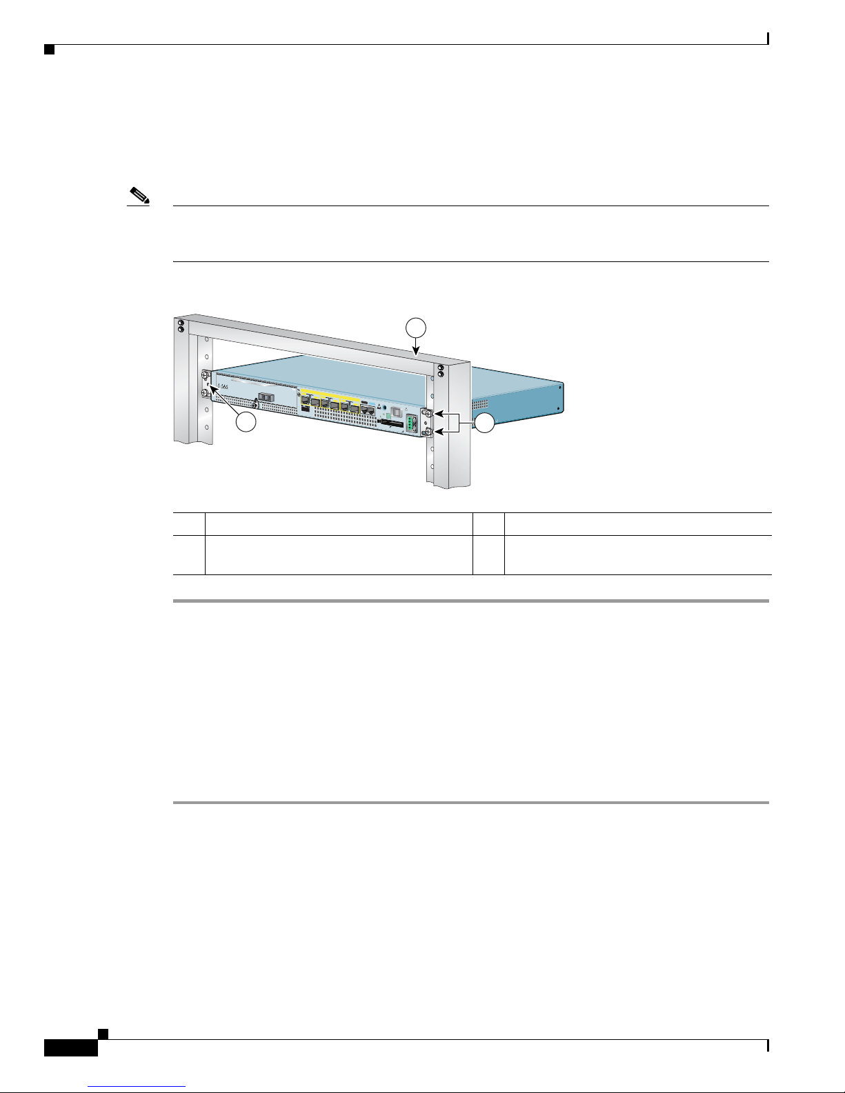
Figure 2-7 Installing the Cisco 7301 Router in a Four-Post Rack
Step 1 Make sure that the port adapter latch is in the locked position and the screw is tightened.
Step 2 Make sure the rack brakes are locked or the rack is stabilized.
Step 3 Position the router so the front is closest to you and lift it carefully into the rack. To prevent injury, avoid
any sudden twists or moves.
Step 4 Slide the chassis into the rack, pushing it back until the brackets meet the mounting strips or posts on
both sides of the rack.
Step 5 Keeping the brackets flush against the posts or mounting strips, align the holes in the brackets with the
holes on the rack or mounting strip.
Step 6 For each bracket, insert and tighten two 12-24 x 0.5-inch screws to the rack.
This completes the procedure for installing the chassis in the rack. Proceed to the “Attaching a Chassis
Ground Connection” section on page 2-12 to continue the installation.
1 Four-post rack 3 Four 12-24 x 0.5-inch screws
2 Screw hole for the cable-management bracket
ALARM
RJ45 EN
LINK
TX RX
GBIC
GIGABIT ETHERNET 0/2
RJ45 EN
LINK
TX RX
GBIC
GIGABIT ETHERNET 0/0
RJ45 EN
LINK
TX
RX
GBIC
GIGABIT ETHERNET 0/1
CISCO 7301
SLOT 1
CONSOLE
AUX
COMPACT
FLASH
STATUS
100-240V, 2 A, 5 0/60 Hz
24V
=
9A, 48 - 60V
=
5A
BA
ENABLED
R
X C
E
LLS
R
X
C
AR
R
IER
R
X A
LAR
M
ATM
80908
1
2
3
Page 42
2-12
Cisco 7301 Installation and Configuration Guide
OL-5418-07
Chapter 2 Rack-Mounting, Tabletop Installation, and Cabling
Attaching a Chassis Ground Connection
Attaching a Chassis Ground Connection
Before you connect power or turn on power to your router, we strongly recommend that you provide an
adequate chassis ground (earth) connection for the router chassis. Chassis ground connectors are
provided on each Cisco 7301 router chassis. (See Figure 2-8 on page 2-12.)
To ensure the chassis ground connection that you provide is adequate, you will need the following parts
an
d tools:
• One grounding lug—Must have two number-10 screw holes that have a 0.63-inch (16.002-mm)
spacing between them, and a wire receptacle large enough to accept a 6-AWG multistrand, copper
wire. This grounding lug is not available from Cisco Systems; electrical-connector vendors provide
this type of grounding lug.
• Two Phillips machine screws with locking washers—M5 (metric), 0.031-inch (0.8-mm) pitch,
0.315-inch (8-mm) length. These screws are not available from Cisco Systems; they are available
from a commercial hardware vendor.
• One grounding wire—6-AWG, 0.162-inch (4.115-mm) diameter, with approximately 0.108-inch
(2.743-mm) insulation, for a total wire diameter of approximately 0.27 inches (6.858 mm). The wire
l
ength is dependent on your router location and site environment. This wire is not available from
Cisco Systems; it is available from a commercial cable vendor.
• Number 2 Phillips screwdriver
• Crimping tool large enough to accommodate the diameter of the wire receptacle on your grounding
lug
• Wire stripper
Figure 2-8 Locating the Chassis Ground Connector
1 Fan vents 2 Chassis ground connector
80267
1
2
Page 43

2-13
Cisco 7301 Installation and Configuration Guide
OL-5418-07
Chapter 2 Rack-Mounting, Tabletop Installation, and Cabling
Attaching a Chassis Ground Connection
Use the following procedure to attach the grounding lug to the chassis ground connector on your router
chassis:
Figure 2-9 Attaching a Grounding Lug to the Chassis Ground Connector
Note The grounding lug and Phillips scres are not available from Cisco Systems. Get the grounding lug from
an electrical-connector vendor and the screws from a hardware vendor. See “Tools and Parts Required”
section on page 2-2.
Step 1 Use the wire stripper to strip one end of the 6-AWG wire approximately 0.75 inches (19.05 mm).
Step 2 Insert the 6-AWG wire (4) into the wire receptacle on the grounding lug.
Step 3 Use the crimping tool to carefully crimp the wire receptacle around the wire; this step is required to
ensure a proper mechanical connection.
Step 4 Locate the chassis ground connector (1) on the rear of your router chassis.
Step 5 Insert the two screws (3) through the holes in the grounding lug (2).
Step 6 Use the Number 2 Phillips screwdriver to carefully tighten the screws until the grounding lug is held
firmly to the chassis. Do not overtighten the screws.
Step 7 Connect the opposite end of the grounding wire to the appropriate grounding point at your site to ensure
an adequate chassis ground.
This completes the procedure for attaching a chassis ground connection. Go to the following cabling
sections for information on attaching cables.
1 Chassis ground connector 3 Screws
2 Grounding lug 4 Wire
50536
1
2
3
4
Page 44

2-14
Cisco 7301 Installation and Configuration Guide
OL-5418-07
Chapter 2 Rack-Mounting, Tabletop Installation, and Cabling
Connecting Port Adapter Cables
Connecting Port Adapter Cables
The instructions for connecting the cables for the port adapter installed in the Cisco 7301 router are
contained in the respective configuration notes for each port adapter. For example, if you are connecting
the optical fiber cables for the PA-POS-OC3 port adapter, refer to the configuration note PA-POS-OC3
Packet OC-3 Port Adapter Installation and Configuration at
http://www.cisco.com/univercd/cc/td/doc/product/core/7206/port_adp/sonet_pa/paposoc3/index.htm.
Port adapter documents are also available on the Documentation CD-ROM.
Connecting I/O Cables
This section contains connection equipment information for the Gigabit Ethernet, console, and auxiliary
ports.
Warning
The ports labeled “Ethernet,” “10BaseT,” “Token Ring,” “Console,” and “AUX” are safety extra-low
voltage (SELV) circuits. SELV circuits should only be connected to other SELV circuits. Because the
BRI circuits are treated like telephone-network voltage, avoid connecting the SELV circuit to the
telephone network voltage (TNV) circuits.
Statement 22
Connecting Console and Auxiliary Port Cables
Note The console cable kit product number is ACS-2500ASYN.
The Cisco 7301 router has a DCE-mode console port for connecting a console terminal, and a DTE-mode
a
uxiliary port for connecting a modem or other DCE device (such as a CSU/DSU or other router) to your
router.
Note Both the console and the auxiliary ports are asynchronous serial ports; any devices connected to these
ports must be capable of asynchronous transmission. (Asynchronous is the most common type of serial
device; for example, most modems are asynchronous devices.)
The Cisco 7301 router uses RJ-45 ports for both the auxiliary port and console port.
Before connecting a terminal to the console port, configure the terminal to match the router console port
as
follows: 9600 baud, 8 data bits, no parity, 1 stop bits (9600 8N1). After you establish normal router
operation, you can disconnect the terminal.
For console and auxiliary port pinouts for the RJ-45 connector, see A
ppendix A, “Cisco 7301 Router
Specifications.”
Ta b l e 2-2 Pinouts for the RJ-45-to-DB-25 Adapters
Adapter DTE M/F Pins
1
DCE M/F Pins MMOD Pins
2
1 4 5 5
2 20 6 8
3 2 3 3
Page 45

2-15
Cisco 7301 Installation and Configuration Guide
OL-5418-07
Chapter 2 Rack-Mounting, Tabletop Installation, and Cabling
Connecting I/O Cables
Refer to Table 2-2 for a list of the pins used on the RJ-45-to-DB-25 adapters, used with an RJ-45 cable,
to connect terminals and modems to the Cisco 7301 router. The cable you use may be a roll-over cable
or
a straight cable.
A roll-over cable can be detected by comparing the two modular ends of the cable. Holding the cables
in
your hand, side-by-side, with the tab at the back, the wire connected to the pin on the outside of the
left plug should be the same color as the pin on the outside of the right plug. If your cable was purchased
from Cisco, pin 1 will be white on one connector, and pin 8 will be white on the other (a roll-over cable
reverses pins 1 and 8, 2 and 7, 3 and 6, and 4 and 5). (See Figure 2-10.)
Figure 2-10 Identifying a Roll-Over Cable
The Cisco 7301 router ships with a rolled cable. Connection to a terminal or a modem will require an
RJ-45-to-DB-25 adapter, and possibly a DB-25-to-DB9 adapter. Refer to Ta ble 2-3 for the cable and
adapter configurations that can be used to connect terminals and modems to the Cisco 7301 router.
4 7 7 7
5 7 7 7
6 3 2 2
7 6 20 20
8 5 4 4
1. The female data terminal equipment (FDTE) adapter that is available from Cisco is labeled “Terminal”.
2. The MMOD adapter that is available from Cisco is labeled “Modem”.
Table 2-2 Pinouts for the RJ-45-to-DB-25 Adapters
Adapter DTE M/F Pins
1
DCE M/F Pins MMOD Pins
2
1 Pin 1 3 Pin 8
2 Pin 1 and pin 8 should be the same color
84532
1 3
2
Page 46

2-16
Cisco 7301 Installation and Configuration Guide
OL-5418-07
Chapter 2 Rack-Mounting, Tabletop Installation, and Cabling
Connecting I/O Cables
Both ports are configured as asynchronous serial ports. Figure 2-11 shows the RJ-45 console and
auxiliary port connections.
Figure 2-11 Console and Auxiliary Port RJ-45 Connectors
Connecting Native Gigabit Ethernet Cables
Note See Chapter 3, “Starting and Configuring the Router,” the “Configuring the Native Gigabit Ethernet
Interfaces” section on page 3-14, for information on configuring and troubleshooting the Gigabit
Ethernet interfaces.
The Cisco 7301 router has three native Gigabit Ethernet interfaces and six physical Gigabit Ethernet
ports, three RJ-45 ports (copper) and three SFP GBIC ports (optical). Only three of the six ports can be
in use at any one time. The three Gigabit Ethernet interfaces are directly connected to the BCM 1250
processor.
Attaching the Gigabit Ethernet Cables
The RJ-45 ports support IEEE 802.u (Fast Ethernet) and 802.3ab (Gigabit Ethernet) twisted-pair
interfaces compliant with 1000BASETX and 1000BASET specifications.
Ta b l e 2-3 Asynchronous Device Cabling Options
Access Server Port RJ-45 Cable Type DB-25 Adapter End Device
Console or auxiliary Rolled FDTE
1
1. The FDTE RJ-45-to-DB-25 adapter is labeled “Terminal”.
Ter m inal
Console or auxiliary Straight FDCE Termin a l
Auxiliary or console Rolled MMOD
2
2. The MMOD RJ-45-to-DB-25 adapter is labeled “Modem”.
Modem
1 Auxiliary port 4 Cable to modem or DCE
2 Console port 5 Cable to console terminal or DTE
3 RJ-45 connector
80273
ALARM
RJ45 EN
LINK
TX RX
GBIC
GIGABIT ETHERNET 0/2
RJ45 EN
LINK
TX RX
GBIC
GIGABIT ETHERNET 0/0
RJ45 EN
LINK
TX RX
GBIC
GIGABIT ETHERNET 0/1
CISCO 7301
CONSOLEAUX
COMPACT
FLASH
STATUS
100-240V, 2A, 50/60 Hz
24V
=
9A, 48 - 60V
=
5A
1
2
3
4 5
BA
Page 47
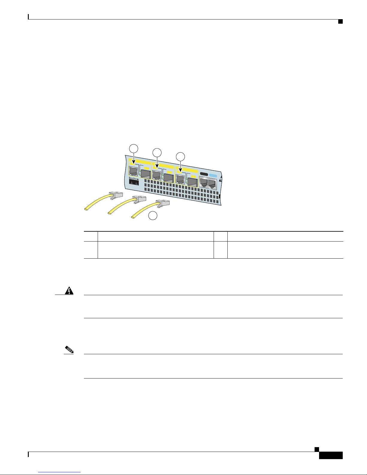
2-17
Cisco 7301 Installation and Configuration Guide
OL-5418-07
Chapter 2 Rack-Mounting, Tabletop Installation, and Cabling
Connecting I/O Cables
The RJ-45 port supports standard straight-through and crossover Category 5 unshielded twisted-pair
(UTP) cables with RJ-45 connectors. Cisco Systems does not supply Category 5 UTP cables; these
cables are available commercially.
See A
ppendix A, “Specifications,” for Gigabit Ethernet RJ-45 port specifications.
Intra-Building Lightning Protection
Shielded cables, which are grounded at both ends, are required to be used on the 10/100/1000 Ethernet
(RJ-45) port in order to be in compliance with requirement R4-11 in GR-1089-Core for a Central Office
environment. This is not a requirement for customer premise installations.
Figure 2-12 Attaching the RJ-45 Port Gigabit Ethernet Cables
Attach one, two, or three Gigabit Ethernet 10/100/1000 cables to Gigabit Ethernet RJ-45 port 0/0, port
0/1, or port 0/2.
Warning
To avoid electric shock, do not connect safety extra-low voltage (SELV) circuits to telephone-network
voltage (TNV) circuits. LAN ports contain SELV circuits, and WAN ports contain TNV circuits. Some
LAN and WAN ports both use RJ-45 connectors. Use caution when connecting cables.
Statement 76
Attaching the SFP GBIC Interface Cables
Note We recommend cleaning the fiber optical cables before connecting them to the fiber optic ports. For
optical-fiber cleaning information, see the Inspection and Cleaning Procedures for Fiber-Optic
Connections document.
The SFP GBIC module ports support IEEE 802.3z (optical Gigabit Ethernet) interfaces compliant with
100
0BASESX and 1000BASELX specifications.
After you install the SFP GBIC module in the Gigabit E
thernet port, you must attach the cables to the
SFP GBIC module. The instructions that follow apply to all supported platforms.
1 Gigabit Ethernet port 0/0 (RJ-45 connector) 3 Gigabit Ethernet port 0/2 (RJ-45 connector)
2 Gigabit Ethernet port 0/1 (RJ-45 connector) 4 Gigabit Ethernet cables with RJ-45
c
onnectors
RJ45 EN
LINK
TX RX
GBIC
GIGABIT ETHERNET 0/2
RJ45 EN
LINK
TX RX
GBIC
GIGABIT ETHERNET 0/0
RJ45 EN
LINK
TX RX
GBIC
GIGABIT ETHERNET 0/1
CISCO 7301
CONSOLE
AUX
CO
FL
80275
1
2
3
4
Page 48

2-18
Cisco 7301 Installation and Configuration Guide
OL-5418-07
Chapter 2 Rack-Mounting, Tabletop Installation, and Cabling
Connecting I/O Cables
Note Optical fiber cables are commercially available; they are not available from Cisco Systems.
Attaching Multimode and Single-Mode Optical Fiber Cables
If you ordered a Gigabit Ethernet SFP GBIC module with your Cisco 7301 router, it is one of three types
listed in Tab l e 2-4:
For cabling specifications, including cabling information, see the online G
igabit Interface Converter
(GBIC) and Small Form-Factor Pluggable (SFP) GBIC Installation Information and Specifications.
For product numbers of SFPs supported on the Cisco 7301, see A
ppendix A, “SFP GBIC Module
Configurations.”
Caution If you plan to use a GLC-LH-SM at distances greater than 984.25 feet (300 meters) over 50/125-micron
or 62.5/125-micron multimode fiber, you must use the mode-conditioning patch cord to prevent data
transmission problems. See the “Attaching the Mode-Conditioning Patch Cord” section on page 2-19.
Warning
Class 1 laser product.
Statement 1008
Warning
Class 1 LED product.
Statement 1027
Ta b l e 2-4 SFP GBIC Products, Description, and Operating Distance
Product Number GBIC Description Operating Distance
GLC-SX-MM= Short wavelength
(
1000BASESX)
Contains a Class 1 laser of
850 nm for 1000BASESX
(sh
ort wavelength)
applications.
Operates on standard
m
ultimode fiber-optic link
spans of up to 1804.5 ft.
(550 m).
GLC-LH-SM= Long wavelength/
long haul
(1
000BASELX/LH)
Contains a Class 1 laser of
1300 nm for
1000BASELX/LH (long
wavelength) applications.
Operates on single-mode
f
iber-optic link spans of up to
6.21 miles (10 km) or
m
ultimode spans up to
1804.5 ft. (550 m) with
mode- conditioning cable.
GLC-ZX-SM= Extended distance
(1
000BASEZX)
Contains a Class 1 laster of
1550 nm for 1000BASEZX
(ext
ended wavelength)
applications.
Operates on ordinary
s
ingle-mode fiber-optic link
spans of up to 43.5 miles (70
km). Link spans of up to 62.1
miles (100 km) are possible
using premium single-mode
fiber or dispersion-shifted
single-mode fiber.
Page 49

2-19
Cisco 7301 Installation and Configuration Guide
OL-5418-07
Chapter 2 Rack-Mounting, Tabletop Installation, and Cabling
Connecting I/O Cables
Figure 2-13 SFP GBIC Port Connections
Step 1 Remove the plug from the SFP GBIC module so that you can insert the cables. Keep the plug for use
should you ever disconnect the optical fiber cables.
Warning
Invisible laser radiation may be emitted from disconnected fibers or connectors. Do not stare into
beams or view directly with optical instruments.
Statement 1051
Step 2 Attach the appropriate optical fiber cable directly to the SFP GBIC module. You can use either simplex
or duplex connectors for most devices. (Figure 2-13 shows a SFP GBIC module with a duplex connector
being installed in SFP GBIC slot 0/1.)
• For simplex connectors, two cables are required, one cable for transmit (TX) and a second cable for
receive (RX).
• For duplex connectors, only one cable that has both TX and RX connectors is required.
A mode-conditioning patch cord can be used with the GLC-LH-SM to allow reliable laser transmission
between the single-mode laser source on the SFP GBIC module and a multimode optical fiber cable. For
installation instructions, see the
“Attaching the Mode-Conditioning Patch Cord” section on page 2-19.
Attaching the Mode-Conditioning Patch Cord
A mode-conditioning patch cord can be used with the GLC-LH-SM to allow reliable laser transmission
between the single-mode laser source on the SFP GBIC and a multimode optical fiber cable.
When an unconditioned laser source designed for operation on single-mode optical fiber is directly
c
oupled to a multimode optical fiber cable, an effect known as differential mode delay (DMD) might
result in a degradation of the modal bandwidth of the optical fiber cable.
This degradation results in a decrease in the link span (the distance between a transmitter and a receiver)
th
at can be supported reliably. The effect of DMD can be overcome by conditioning the launch
characteristics of a laser source. A practical means of performing this conditioning is to use a device
called a mode-conditioning patch cord.
1 To external 1000BASEX network 4 Gigabit Ethernet SFP GBIC port 0/1
2 Duplex connector (TX and RX) 5 TX (SFP GBIC port 0/1)
3 SFP GBIC module 6 RX (SFP GBIC port 0/1)
RJ45 EN
LINK
TX RX
GBIC
GIGABIT ETHERNET 0/2
LINK
TX RX
GBIC
ABIT ETHERNET 0/0
RJ45 EN
LINK
TX RX
GBIC
GIGABIT ETHERNET 0/1
CISCO 7400
SERIES
CISCO 7411
CONSOLE
AUX
CO
FL
80749
1 3
4
6
2
5
Page 50

2-20
Cisco 7301 Installation and Configuration Guide
OL-5418-07
Chapter 2 Rack-Mounting, Tabletop Installation, and Cabling
Connecting I/O Cables
A mode-conditioning patch cord is an optical fiber cable assembly that consists of a pair of optical fibers
terminated with connector hardware. Specifically, the mode-conditioning patch cord is composed of a
single-mode optical fiber permanently coupled off-center (see Offset in Figure 2-14) to a graded-index
multimode optical fiber. Figure 2-14 shows a diagram of the mode-conditioning patch cord assembly.
Figure 2-14 SFP Mode-Conditioning Patch Cord
Note Figure 2-14 shows one type of mode-conditioning patch cord.
To use a mode-conditioning patch cord, follow these steps:
Step 1 Attach a patch cord to the SFP GBIC module. (See Figure 2-13.)
Step 2 Attach the network ends of your patch cord to the appropriate 1000BASEX equipment in your building
cable plant.
Ensure that you connect the TX and RX ports on one end of the patch cord to the RX and TX ports
(r
espectively) on the other end. Connect TX to RX and RX to TX.
This completes the procedures for connecting the I/O cables.
1 Gray color identifier 5 Single-mode bar
2 To GE interface 6 Offset
3 Blue color identifier 7 Beige color identifier
4 Multimode bar 8 To cable plant
/ / / /
/ /
TX
Offset
RX
84159
1 7
2
3 7
4
8
65 4
Page 51

2-21
Cisco 7301 Installation and Configuration Guide
OL-5418-07
Chapter 2 Rack-Mounting, Tabletop Installation, and Cabling
Attaching the Alarm Port Cable
Attaching the Alarm Port Cable
Figure 2-15 Connecting the Alarm Port Cable
If you have an alarm system, attach the alarm cable to the Cisco 7301 router alarm port. The alarm port
cable is not provided by Cisco Systems. Insert the cable connector into the alarm port. The cable
connector cannot be incorrectly inserted into the alarm port.
The alarm port is used to monitor fatal or severe errors that cause Cisco IOS to crash. The alarm port is
c
onnected to a normally closed solid state relay. Cisco IOS writes to a hardware port and the relay
c
ontact opens. If the system enters into a ROMmon or watchdog reset state, the relay contacts close. The
closing contacts alert the alarm annunciator or monitor that a Cisco IOS crash has occurred.
If interfaces fail or other non-fatal errors occur, the alarm port does not respond. Continue to use SNMP
t
o manage these types of errors.
For alarm port specifications, see A
ppendix A, “Specifications,” the “Alarm Port” section on page A-9.
Using the Cable-Management Bracket
Figure 2-16 Securing Interface Cables Through the Cable-Management Bracket
1 Alarm port
80279
ALARM
CONSOLE
COMPACT
FLASH
STATUS
1
1 Input/output cables 2 Cable-management bracket
ENABLED
RX CELLS
RX CARRIER
RX ALARM
ATM
ALARM
RJ45 EN
LINK
TX RX
GBIC
GIGABIT ETHERNET 0/2
RJ45 EN
LINK
TX
RX
GBIC
GIGABIT ETHERNET 0/0
RJ45 EN
LINK
TX RX
GBIC
GIGABIT ETHERNET 0/1
CISCO 7400
SERIES
CISCO 7301
SLOT 1
CONSOLE
AUX
COMPACT
FLASH
STATUS
100-240V, 2A, 50/60 Hz
24V
=
9A, 48 - 60V
=
5A
80280
1
2
BA
Page 52

2-22
Cisco 7301 Installation and Configuration Guide
OL-5418-07
Chapter 2 Rack-Mounting, Tabletop Installation, and Cabling
Connecting Power
Secure port adapter interface cables and input/output cables by placing them through the
cable-management bracket.
Proceed to the “C
onnecting Power” section on page 2-22 to complete the installation.
Connecting Power
This section provides the procedures for connecting AC-input and DC-input power to your Cisco 7301
router.
Warning
This unit might have more than one power supply connection. All connections must be removed to
de-energize the unit.
Statement 1028
Warning
This product relies on the building’s installation for short-circuit (overcurrent) protection. Ensure that
a fuse or circuit breaker no larger than 120 VAC, 15A U.S. (240 VAC, 10A international) is used on the
phase conductors (all current-carrying conductors).
Statement 13
Connecting AC-Input Power
Figure 2-17 Dual-AC Power Supply Cables
84234
ALARM
COMPACT
FLASH
STATUS
100-240V, 2A, 50/60 Hz
24V
=
9A, 48 - 60V
=
5A
Page 53

2-23
Cisco 7301 Installation and Configuration Guide
OL-5418-07
Chapter 2 Rack-Mounting, Tabletop Installation, and Cabling
Connecting Power
Figure 2-18 Connecting AC-Input Power
Connect an AC-input power supply as follows:
Step 1 At the front of the router, check that the power switch is in the off (O) position.
Step 2 Plug the single power cable into the AC connector on the router, or if you have a dual-AC power supply,
plug an AC power cable into each AC connector. The dual AC power supply cables are attached with
screws to the chassis.
Step 3 If you have a single AC power supply, insert the cable-retention clip wire into the clip bracket holes.
Then slide the plastic portion into the clip, adjusting it to the desired length. See Figure 2-18.
Step 4 Place the AC power cable in the adjustable cable-retention clip. The plastic part that grips the cable can
be removed from the supporting wire and repositioned for better support of the cable.
Step 5 Plug the AC power supply cable into the AC power source. Repeat this step if you have a dual-AC power
supply.
Note After powering off the router, wait a minimum of 30 seconds before powering it on again.
Note If required, use Sinewave Output UPS (uninterruptable power supply), not Ferro-resonant type UPS.
This completes the procedure for connecting AC-input power. Your installation is complete. Proceed to
Chapter 3, “Starting and Configuring the Router,” to start the router and to perform a basic configuration.
Connecting DC-Input Power
Note The color coding of the DC-input power supply leads depends on the color coding of the DC power
source at your site. Make certain the lead color coding you choose for the DC-input power supply
matches lead color coding used at the DC power source.
Warning
When you install the unit, the ground connection must always be made first and disconnected last.
Statement 1046
1 AC power receptacle 2 Adjustable AC power cable-retention clip
80281
ALARM
LE
COMPACT
FLASH
STATUS
100-24 0V, 2A, 50/60 Hz
24V
=
9A, 48 - 60 V
=
5A
2
1
Page 54

2-24
Cisco 7301 Installation and Configuration Guide
OL-5418-07
Chapter 2 Rack-Mounting, Tabletop Installation, and Cabling
Connecting Power
Warning
Before connecting or disconnecting ground or power wires to the chassis, ensure that power is
removed from the DC circuit. To ensure that all power is OFF, locate the circuit breaker on the panel
board that services the DC circuit, switch the circuit breaker to the OFF position, and tape the switch
handle of the circuit breaker in the OFF position.
Statement 140
Warning
This product relies on the building’s installation for short-circuit (overcurrent) protection. Ensure that
a Listed and Certified fuse or circuit breaker no larger than 60 VDC, 15 A is used on all
currently-carrying conductors.
Statement 96
Caution The DC return connection to this system is to remain isolated from the system frame and chassis (DC-I).
Connect a DC-input power supply as follows:
Step 1 At the front of the router, check that the power switch is in the off (O) position.
Step 2 Ensure that no current is flowing through the DC power supply leads. To ensure that all power is off,
locate the circuit breaker on the panel board that services the DC circuit, switch the circuit breaker to
the off position, and tape the switch handle of the circuit breaker in the off position.
Step 3 Using a wire stripper, strip approximately 0.55 inch (14 mm) from the –V and +V leads.
Figure 2-19 Attaching the Leads to the DC Plug and the DC Plug to the DC Connector
Step 4 Insert the –V and +V leads into the DC plug that ships with the Cisco 7301 router. The plug allows you
to unplug the DC wires from the power supply without having to unscrew the leads.
a. Orient the plug (1) to the connector (4) as shown in Figure 2-19. The plug inserts only one way.
Notice the symbols, + A –, embossed on the connector (3). Use the symbols and the orientation of
th
e plug to guide you when inserting the leads into the plug.
b. Insert the +V lead (2) into the plug as shown in Figure 2-19, and tighten the screw to hold the lead
to the plug.
1 DC plug 4 Single DC power connector
2 Lead 5 Dual DC power connector
3 + and – embossed on connector
BA
50538
BA
4
5
1
3
2
Page 55

2-25
Cisco 7301 Installation and Configuration Guide
OL-5418-07
Chapter 2 Rack-Mounting, Tabletop Installation, and Cabling
Connecting Power
c. Insert the –V lead into the plug as shown in Figure 2-19, and tighten the screw to hold the lead to
the plug.
Step 5 If you have a dual DC power supply, repeat Step 4 for the second plug.
Step 6 Insert the DC plug into the DC power connector on the chassis. If you have a dual DC power supply,
insert the second DC plug into the DC power connector.
Step 7 Switch the circuit breaker to the on position.
Step 8 Press the power switch to turn on the router.
For information on Cisco 7301 product specifications and power supply, refer to Ci
sco 7301 Router Data
Sheet at the following URL:
https://www.cisco.com/en/US/prod/collateral/route
rs/ps352/ps4972/product_data_sheet09186a008014
611a.html
Note After powering off the router, wait a minimum of 30 seconds before powering it on again.
This completes the procedure for connecting DC-input power. Your installation is complete. Proceed to
Chapter 3, “Starting and Configuring the Router,” to start the router and to perform a basic configuration.
Page 56

2-26
Cisco 7301 Installation and Configuration Guide
OL-5418-07
Chapter 2 Rack-Mounting, Tabletop Installation, and Cabling
Connecting Power
Page 57

CHAPTER
3-1
Cisco 7301 Installation and Configuration Guide
OL-5418-07
3
Starting and Configuring the Router
This chapter describes how to start the system and perform a basic configuration for your Cisco 7301
router. The chapter contains the following sections:
• Functional Overview, page 3-1
• Checking Conditions Prior to System Startup, page 3-8
• Starting the System and Observing Initial Conditions, page 3-9
• Configuring a Cisco 7301 Router, page 3-10
• Enabling the Second Processor, page 3-20
• Saving the Running Configuration to NVRAM, page 3-27
• Checking the Running Configuration Settings, page 3-27
• Performing Other Configuration Tasks, page 3-27
• Upgrading ROMmon on the Cisco 7301, page 3-27
• Troubleshooting the Upgrade, page 3-30
• Replacing or Recovering a Lost Password, page 3-31
• Viewing Your System Configuration, page 3-34
• Performing Complex Configurations, page 3-35
This chapter guides you through a basic router configuration, which is sufficient for you to access your
ne
twork. Complex configuration procedures are beyond the scope of this publication and can be found
in the modular configuration and modular command reference publications in the Cisco IOS software
co
nfiguration documentation set that corresponds to the software release installed on your Cisco
hardware.
To configure a Cisco 7301 router from a console, you need to connect a terminal to the router console
por
t.
Functional Overview
This section provides a functional overview of the Cisco 7301 router. It describes the numbering and
addressing scheme of the port adapter for the router, the environmental monitoring and reporting
functions, and online insertion and removal (OIR). These descriptions help you become familiar with
the capabilities of the Cisco 7301 router.
Page 58

3-2
Cisco 7301 Installation and Configuration Guide
OL-5418-07
Chapter 3 Starting and Configuring the Router
Functional Overview
Chassis Slot and Logical Interface Numbering
In the Cisco 7301 router, the port-adapter-slot-number is the chassis slot in which a port adapter is
installed, whereas the logical-interface-number is the physical location of the interface port on a port
adapter.
The port adapter slot in the Cisco 7301 router is numbered slot 1. Port adapter slot 0 is always reserved
fo
r logical ports 10/100/1000.
The Media Access Control (MAC) or hardware address is a standardized data link layer address that is
re
quired for certain network interface types. These addresses are not used by other devices in the
network; they are specific and unique to each port. The Cisco 7301 router uses a specific method to
assign and control the MAC addresses of its port adapters. For a description of the MAC address, see the
“MAC Address” section on page 3-3.
You can identify port adapter slots by using software commands. To display information about all port
ad
apter slots, use the show interfaces command. To display information about a specific port adapter
slot, use the show interfaces command with the port adapter type and slot number in the format
show interfaces port
-adapter-type slot-number/port-number. If you abbreviate the command (sh int)
and do not specify port adapter type and slot number (or arguments), the system interprets the command
as show interfaces and displays the status of all port adapters and ports.
The following example shows how the s
how interfaces command, used without arguments, displays
status information (including the physical port adapter number) for the port adapter in a Cisco 7301
router.
In the following example, most of the status information for each interface is omitted.
Router# show interfaces
GigabitEthernet0/0 is up, line protocol is up
Hardware is BCM1250 Internal MAC, address is 0005.dd2c.7c1b (bia 0005.dd2c.7c1b)
Internet address is 10.1.3.153/16
MTU 1500 bytes, BW 100000 Kbit, DLY 100 usec,
reliability 255/255, txload 1/255, rxload 1/255
Encapsulation ARPA, loopback not set
Keepalive set (10 sec)
Half-duplex, 100Mb/s, media type is RJ45
output flow-control is off, input flow-control is off
ARP type:ARPA, ARP Timeout 04:00:00
Last input 00:00:01, output 00:00:07, output hang never
Last clearing of "show interface" counters 19:00:50
Input queue:0/75/63658/0 (size/max/drops/flushes); Total output drops:0
(display text omitted)
GigabitEthernet0/1 is up, line protocol is up
Hardware is BCM1250 Internal MAC, address is 0005.dd2c.7c1a (bia 0005.dd2c.7c1a)
Internet address is 192.18.1.1/24
MTU 1500 bytes, BW 1000000 Kbit, DLY 10 usec,
reliability 255/255, txload 5/255, rxload 6/255
Encapsulation ARPA, loopback not set
Keepalive set (10 sec)
Full-duplex, 1000Mb/s, link type is autonegotiation, media type is SX
output flow-control is off, input flow-control is off
ARP type:ARPA, ARP Timeout 04:00:00
Last input 18:56:46, output 00:00:09, output hang never
Last clearing of "show interface" counters 19:00:52
Input queue:0/75/16176489/0 (size/max/drops/flushes); Total output drops:0
(display text omitted)
GigabitEthernet0/2 is up, line protocol is up
Page 59

3-3
Cisco 7301 Installation and Configuration Guide
OL-5418-07
Chapter 3 Starting and Configuring the Router
Functional Overview
Hardware is BCM1250 Internal MAC, address is 0005.dd2c.7c19 (bia 0005.dd2c.7c19)
Internet address is 1.1.1.1/24
MTU 1500 bytes, BW 1000000 Kbit, DLY 10 usec,
reliability 255/255, txload 1/255, rxload 5/255
Encapsulation ARPA, loopback not set
Keepalive set (10 sec)
Full-duplex, 1000Mb/s, link type is autonegotiation, media type is SX
output flow-control is off, input flow-control is off
ARP type:ARPA, ARP Timeout 04:00:00
Last input 00:04:42, output 00:00:01, output hang never
Last clearing of "show interface" counters 19:00:54
Input queue:0/75/22087/0 (size/max/drops/flushes); Total output drops:0
(display text omitted)
You can also use arguments such as the interface type (Ethernet, Token Ring, ATM, and so forth) and
the port address (slot-number/port-number) to display information about a specific interface only.
The following example shows the display for the first port on the Gigabit Ethernet port:
Router# show interfaces g0/0
GigabitEthernet0/0 is up, line protocol is up
Hardware is BCM1250 Internal MAC, address is 0005.dd2c.7c1b (bia 0005.dd2c.7c1b)
Internet address is 10.1.3.153/16
MTU 1500 bytes, BW 100000 Kbit, DLY 100 usec,
reliability 255/255, txload 1/255, rxload 1/255
Encapsulation ARPA, loopback not set
Keepalive set (10 sec)
Half-duplex, 100Mb/s, media type is RJ45
output flow-control is off, input flow-control is off
ARP type:ARPA, ARP Timeout 04:00:00
Last input 00:00:00, output 00:00:01, output hang never
Last clearing of "show interface" counters 19:04:04
Input queue:0/75/63658/0 (size/max/drops/flushes); Total output drops:0
(display text omitted)
For complete descriptions and instructions of the commands used to configure your Cisco 7301 router,
refer to the Cisco IOS Configuration Fundamentals Configuration Guide and Cisco IOS Configuration
Fundamentals Command Reference publications at the following URL:
http://www.cisco.com/en/US/products/sw/iosswrel/tsd_products_support_category_home.html
MAC Address
All LAN interfaces (ports) require unique MAC addresses, also known as hardware addresses. Typically,
the MAC address of an interface is stored on a memory component that resides directly on the interface
circuitry; however, the OIR feature requires a different method. (For a description of OIR, see the
“Online Insertion and Removal” section on page 3-4.)
Using OIR, you can remove a port adapter and replace it with another identically configured one. If the
ne
w port adapter matches the port adapter you removed, the system immediately brings it online. In order
to enable OIR, an address allocator with unique MAC addresses is stored in an EEPROM on the system
board. Each address is reserved for a specific port and slot in the router regardless of whether a port
adapter resides in that slot. The MAC address for the port adapter slot in the Cisco 7301 is slot 0. You
can remove a port adapter and insert it into another router without causing the MAC addresses to move
around the network or be assigned to multiple devices.
Page 60

3-4
Cisco 7301 Installation and Configuration Guide
OL-5418-07
Chapter 3 Starting and Configuring the Router
Functional Overview
Note that if the MAC addresses were stored on each port adapter, OIR would not function because you
could never replace one port adapter with an identical one; the MAC addresses would always be
different. Also, each time a port adapter was replaced, other devices on the network would have to update
their data structures with the new address. If the other devices did not update quickly enough, the same
MAC address could appear in more than one device at the same time.
Note Storing the MAC addresses for every slot in one central location means the addresses stay with the
memory device on which they are stored.
Online Insertion and Removal
All port adapters and service adapters in the Cisco 7301 routers support online insertion and removal
(OIR). However, it is wise to shut down the interface before removing a port adapter that has active
traffic moving through it. Removing a port adapter while traffic is flowing through the ports can cause
system disruption. Once the port adapter is inserted, the ports can be brought back up.
Note As you disengage the port adapter from the router or switch, online insertion and removal (OIR)
administratively shuts down all active interfaces in the port adapter.
OIR allows you to install and replace port adapters and service adapters while the router is operating;
you do not need to notify the software or shut down the system power, although you should not run traffic
through the port adapter you are removing while it is being removed. OIR is a method that is seamless
to end users on the network, maintains all routing information, and preserves sessions.
The following is a functional description of OIR for background information only; for specific
pr
ocedures for installing and replacing a port adapter or service adapter in a Cisco 7301 router, refer to
the online configuration note for each port adapter or service adapter.
Each port adapter or service adapter has a bus connector that connects it to the router. The connector has
a
set of tiered pins in three lengths that send specific signals to the system as they make contact with the
port adapter or service adapter. The system assesses the signals it receives and the order in which it
receives them to determine if a port adapter or service adapter is being removed or inserted into the
system. From these signals, the system determines whether to reinitialize a new interface or shut down
a removed interface.
For example, when you insert a port adapter or service adapter, the longest pins make contact with the
p
ort adapter or service adapter first, and the shortest pins make contact last. The system recognizes the
signals and the sequence in which it receives them.
When you remove or insert a port adapter or service adapter in a Cisco 7301 router, the pins send signals
to
notify the system, which then performs as follows:
1. Rapidly scans the system for configuration changes.
2. Initializes all newly inserted port adapters or service adapters, noting any removed interfaces and
placing them in the administratively shutdown state.
3. Brings all previously configured interfaces on the port adapter back to the state they were in when
they were removed. Any newly inserted interface is put in the administratively shutdown state, as if
it was present (but not configured) at boot time. If a similar port adapter type is reinserted into a slot,
its ports are configured and brought online up to the port count of the original port adapter. (A
service adapter has no configurable ports.)
Page 61

3-5
Cisco 7301 Installation and Configuration Guide
OL-5418-07
Chapter 3 Starting and Configuring the Router
Functional Overview
Environmental Monitoring and Reporting Functions
Environmental monitoring and reporting functions allow you to maintain normal system operation by
identifying and resolving adverse conditions prior to loss of operation. The environmental monitoring
functions constantly monitor the internal chassis air temperature and DC supply voltages and currents.
If conditions reach shutdown thresholds, the system shuts down to avoid equipment damage from
excessive heat. The reporting functions periodically log the values of measured parameters so that you
can retrieve them for analysis later, and the reporting functions display warnings on the console if any
of the monitored parameters exceed defined thresholds.
Environmental Monitoring
The environmental monitoring functions use two sensors, Sensor 1 (U62) on the underneath front edge
of the system board, and Sensor 2 (U5), near the fans. If the air temperature exceeds a defined threshold,
the system controller displays warning messages on the console terminal, and if the temperature exceeds
the shutdown threshold, the system controller shuts down the system. The system stores the present
parameter measurements for both temperature and DC voltage in NVRAM so you can retrieve them later
as a report of the last shutdown parameters.
If an internal power supply temperature or voltage reaches a critical level, the power supply shuts down
wi
thout any interaction with the system processor.
The environmental monitoring functions use the following levels of status conditions to monitor the
syste
m:
• Normal—All monitored parameters are within normal tolerances.
• Warning—The system has exceeded a specified threshold. The system continues to operate, but
operator action is recommended to bring the system back to a normal state.
• Critical—An out-of-tolerance temperature or voltage condition exists. The system continues to
operate; however, the system is approaching shutdown. Immediate operator action is required.
• Shutdown—The processor has detected a temperature condition that could result in physical damage
to system components and has disabled DC power to all internal components. This condition
requires immediate operator action. All DC power remains disabled until you toggle the power
switch. Before any shutdown, the system logs the status of monitored parameters in NVRAM so you
can retrieve it later to help determine the cause of the problem.
• Power supply shutdown—The power supply detected an internal out-of-tolerance overvoltage,
overcurrent, or temperature condition and shut itself down. All DC power remains disabled until you
toggle the power switch.
Table 3-1 lists th
e typical temperature thresholds for the Cisco 7301 router, and Tab le 3-2 lists the DC
power thresholds for the normal, warning, and critical (power supply-monitored) levels.
Ta b l e 3-1 Typical Processor-Monitored Temperature Thresholds
Parameter High Warning High Critical Shutdown
Sensor 1 (U62, beneath the front edge
o
f the system board under the port
adapter slot)
113oF (45oC) 122oF (50oC) 131oF (55oC)
Sensor 2 (U5, near the fans, top of
sy
stem board)
122oF (50oC) 131oF (55oC) 140oF (60oC)
Page 62

3-6
Cisco 7301 Installation and Configuration Guide
OL-5418-07
Chapter 3 Starting and Configuring the Router
Functional Overview
Note Table 3-2 shows output from the show environment table command.
Reporting Functions
The Cisco 7301 router displays warning messages on the console if chassis interface-monitored
parameters exceed a desired threshold. You can also retrieve and display environmental status reports
with the show environment, show environment all, show environment last, and show environment
table commands. Parameters are measured and reporting functions are updated every
60 seconds. A brief description of each of these commands follows.
Caution To prevent overheating the chassis, ensure that your system is drawing cool inlet air. Overtemperature
conditions can occur if the system is drawing in the exhaust air of other equipment. Ensure adequate
clearance around the sides of the chassis so that cooling air can flow through the chassis interior
unimpeded and exhaust air exits the chassis and is not drawn into the inlet vent of another device.
The show environment command displays reports of the current environmental system status. The
report displays parameters that are out of the normal values. No parameters are displayed if the system
status is normal. The example that follows shows the display for a system in which all monitored
parameters are within normal range:
Router# show environment
All measured values are normal
If the environmental status is not normal, the system reports the worst-case status level. Following is a
sample overvoltage warning:
Router# show environment
Warning:+3.45 V measured at +3.27 V
The show environment last command retrieves and displays the NVRAM log, which shows the reason
for the last system shutdown (if the shutdown was related to voltage or temperature) and the
environmental status at that time. Air temperature is measured and displayed, and the DC voltage
supplied by the power supply is also displayed.
Ta b l e 3-2 Typical Power Supply-Monitored DC-Voltage Thresholds
Parameter Low Critical Low Warning High Warning High Critical
+3.30V +2.96 +3.12 +3.46 +3.62
+2.50V +2.24 +2.37 +2.62 +2.75
+12.25V +11.03 +11.65 +12.87 +13.49
+5.00V +4.50 +4.74 +5.24 +5.50
–12.00V –10.82 –11.39 –12.58 –13.20
+5.20V +4.68 +4.94 +5.46 +5.72
+1.50V +1.34 +1.41 +1.58 +1.65
+1.20V +1.07 +1.15 +1.26 +1.32
+1.25V +1.12 +1.18 +1.30 +1.37
Page 63

3-7
Cisco 7301 Installation and Configuration Guide
OL-5418-07
Chapter 3 Starting and Configuring the Router
Functional Overview
Following is sample output of the show environment last command:
Router# show environment last
chassis inlet previously measured at 30C/86F
chassis outlet 1 previously measured at 28C/82F
chassis outlet 2 previously measured at -1C/31F
chassis outlet 3 previously measured at -1C/31F
+3.45 V previously measured at +3.27
+5.15 V previously measured at +5.01
+12.15 V previously measured at +12.34
-11.95 V previously measured at -12.41
last shutdown reason - power supply shutdown
The show environment table command displays the temperature and voltage thresholds for each
temperature sensor and for each monitored status level. These thresholds are related to those listed in
Table 3-1 and Tab le 3-2. The display also lists the shutdown threshold for the system.
Following is sample output of the show environment table co
mmand for a Cisco 7301 router:
Router# show environment table
Sample Point LowCritical LowWarning HighWarning HighCritical
Thermal Sensor 1 45C/113F 50C/122F
Thermal Sensor 2 50C/122F 55C/131F
+3.30 V +2.96 +3.12 +3.46 +3.62
+2.50 V +2.24 +2.37 +2.62 +2.75
+12.25 V +11.03 +11.65 +12.87 +13.49
+5.00 V +4.50 +4.74 +5.24 +5.50
-12.00 -10.82 -11.39 -12.58 -13.20
+5.20 V +4.68 +4.94 +5.46 +5.72
+1.50 V +1.34 +1.41 +1.58 +1.65
+1.20 V +1.07 +1.15 +1.26 +1.32
+1.25 V +1.12 +1.18 +1.30 +1.37
System shutdown for Thermal Sensor 1 is 55C/131F
System shutdown for Thermal Sensor 2 is 60C/140F
Note Temperature ranges and values are subject to change.
The s
how environment all command displays an extended report that includes temperature readings and
voltage readings. The show environment all command also displays a report showing which power
supply slots are occupied and which are empty.
Following is sample output of the s
how environment all command.
With AC power supply installed:
Router# sh environment all
Power Supplies:
Power Supply is Internal AC Power Supply. Unit is on.
Temperature readings:
Thermal Sensor 1 measured at 28C/82F
Thermal Sensor 2 measured at 33C/91F
Voltage readings:
+3.30 V measured at +3.27 V
+2.50 V measured at +2.46 V
+12.25 V measured at +12.17 V
+5.00 V measured at +4.94 V
-12.00 V measured at -12.01 V
+5.20 V measured at +5.20 V
+1.50 V measured at +1.48 V
Page 64

3-8
Cisco 7301 Installation and Configuration Guide
OL-5418-07
Chapter 3 Starting and Configuring the Router
Checking Conditions Prior to System Startup
+1.20 V measured at +1.20 V
+1.25 V measured at +1.23 V
Fans:
Fan 1 is believed to be working
Fan 2 is believed to be working
Fan 3 is believed to be working
Fan 4 is believed to be working
Fan 5 is believed to be working
Envm stats saved 0 time(s) since reload
Fan Failures
When the system power is on, all five fans should be operational. The system continues to operate if a
fan fails. When a fan fails, the system displays the following message:
router: 00:03:46:%ENVM-3-BLOWER:Fan 2 may have failed
If the air temperature exceeds a defined threshold, the system controller displays warning messages on
the console terminal, and if the temperature exceeds the shutdown threshold, the system controller shuts
down the system.
If the system does shut down because the temperature exceeded the shutdown threshold, the system
di
splays the following message on the console screen and in the environment display when the system
restarts:
Queued messages:
%ENVM-1-SHUTDOWN: Environmental Monitor initiated shutdown
For complete descriptions and instructions for the environmental monitor commands, refer to the Cisco
IOS Configuration Fundamentals Configuration Guide and Cisco IOS Configuration Fundamentals
Command Reference publications, which are available online.
Checking Conditions Prior to System Startup
Check the following conditions before you start your router:
• The port adapter is inserted in its slot and the port adapter latch is in the locked position.
• The network interface cable is connected to the port adapter.
• A CompactFlash Disk is installed.
• The console terminal is turned on.
You are now ready to start your router. Proceed to the section “Sta
rting the System and Observing Initial
Conditions.”
Page 65

3-9
Cisco 7301 Installation and Configuration Guide
OL-5418-07
Chapter 3 Starting and Configuring the Router
Starting the System and Observing Initial Conditions
Starting the System and Observing Initial Conditions
After installing your Cisco 7301 router and connecting cables, start the router as follows:
Step 1 At the front of the router, place the power switch on the power supply in the on (|) position.
Step 2 Listen for the fans; you should immediately hear them operating.
Step 3 During the boot process, observe the system LEDs. The LEDs on the port adapter go on and off in
irregular sequence. They may go on, go out, and go on again for a short time. On the router, the green
STATUS LED comes on and stays on.
Step 4 Observe the initialization process. When the system boot is complete (a few seconds), the processor
begins to initialize the port adapter and the I/O subsystem. During this initialization, the LEDs on the
port adapter probably will flash on and off.
The enabled LED on the port adapter goes on when initialization is completed, and the console screen
di
splays a script and system banner similar to the following:
Cisco Internetwork Operating System Software
IOS (tm) 7301 Software (C7301-JS-M), Version 12.2(V99.1)Copyright (c) 1986-2001 by cisco
Systems, Inc.
Compiled Sat 19-May-01 11:31 by
Image text-base:0x60008960, data-base:0x617CA000
Step 5 When you start up the router for the first time, the system automatically enters the setup facility, which
determines which port adapter is installed and prompts you for configuration information. On the
console terminal, after the system displays the system banner and hardware configuration, you will see
the following System Configuration Dialog prompt:
--- System Configuration Dialog ---
At any point you may enter a questions mark ‘?’ for help.
Use ctrl-c to abort configuration dialog at any prompt.
Default settings are in square brackets ‘[]’.
continue with configuration dialog? [yes]:
You have the option of proceeding with the setup facility to configure the interfaces, or exiting from
setup and using configuration commands to configure global (system-wide) and interface-specific
parameters. You do not have to configure the interfaces immediately; however, you cannot enable the
interfaces or connect them to any networks until you have configured them.
Many of the port adapter LEDs do not go on until you have configured the interfaces. To verify correct
operation of each interface, complete the first-time startup procedures and configuration, and then refer
to the configuration note for the port adapter for LED descriptions and to check the status of the
interfaces.
If the system does not complete each of the steps in the startup procedure, proceed to Cha
pter 5,
“Troubleshooting Initial Startup Problems” for troubleshooting recommendations and procedures.
Page 66

3-10
Cisco 7301 Installation and Configuration Guide
OL-5418-07
Chapter 3 Starting and Configuring the Router
Configuring a Cisco 7301 Router
Configuring a Cisco 7301 Router
Before configuring the router, determine whether or not you want to use a management tool such as
Cisco Security Device Manager.
Cisco Security Device Manager (SDM), version 1.1, is an optional Java-based device-management tool
th
at allows you to configure LAN interfaces, routing, Network Address Translation (NAT), firewalls,
Virtual Private Networks (VPNs), and other features without knowledge of the Cisco command-line
interface (CLI). You can configure features such as Access Control Lists (ACLs), routing protocols, and
other options using the advanced mode SDM.
Note You will need to use CLI commands to configure several features that SDM does not support. SDM does
not support the following features: WAN configuration, Gigabit Ethernet (GE) interfaces, AA client, EZ
VPN server, QoS, SSHv2, DHCP server configuration options, and usability enhancements.
SDM is preinstalled on your router’s flash disk or compactflash disk when it is ordered as part of a VPN
bundle or as part of a 7xxx VPN bundle. If your router did not ship with SDM preinstalled, you can
download a free copy from the Software Center at Cisco.com at
http://ww.cisco.com/kobayashi/sw-center/index.shtm. Because SDM uses a GUI, it requires that you
access it from a PC using a supported web browser. Go to the Cisco Router and Security Device Manager
(SDM) User Guide for the Cisco 7200 VXR and Cisco 7301 Routers d
ocumentation for more information.
You can configure your Cisco 7301 router using one of the procedures described in the following
se
ctions:
• Performing a Basic Configuration Using AutoInstall, page 3-10
• Performing a Basic Configuration Using the Setup Facility, page 3-11
• Performing a Basic Configuration Using Global Configuration Mode, page 3-20
Follow the procedure that best fits the needs of your network configuration.
Note You need to acquire the correct network addresses from your system administrator or consult your
network plan to determine correct addresses before you can complete the router configuration.
Before continuing the configuration process, check the current state of the router by entering the show
version command. The show version command displays the release of Cisco IOS software that is
available on the router. Sample output of the show version command appears in the “Viewing Your
System Configuration” section on page 3-34.
Performing a Basic Configuration Using AutoInstall
The AutoInstall process is designed to configure the Cisco 7301 router automatically after connection
to your WAN. For AutoInstall to work properly, a TCP/IP host on your network must be preconfigured
to provide the required configuration files. The TCP/IP host may exist anywhere on the network as long
as the following two conditions are maintained:
1. The host must be on the remote side of the router synchronous serial connection to the WAN.
2. User Datagram Protocol (UDP) broadcasts to and from the router and the TCP/IP host are enabled.
Page 67

3-11
Cisco 7301 Installation and Configuration Guide
OL-5418-07
Chapter 3 Starting and Configuring the Router
Configuring a Cisco 7301 Router
This functionality is coordinated by your system administrator at the site where the TCP/IP host is
located. You should not use AutoInstall unless the required files are available on the TCP/IP host. Refer
to the Cisco IOS Configuration Fundamentals Configuration Guide and Cisco IOS Configuration
Fundamentals Command Reference publications for information about how AutoInstall works.
Complete the following steps to prepare your Cisco 7301 router for the AutoInstall process:
Step 1 Attach the appropriate synchronous serial cable to synchronous serial interface 0 on the router.
Step 2 Turn the power switch on the power supply to the on (|) position. (This action turns on AC power to the
router.)
The router loads the operating system image from Flash memory. If the remote end of the WAN
co
nnection is connected and properly configured, the AutoInstall process begins.
Once the AutoInstall process is completed, use the c
opy running-config startup-config command to
write the configuration data to the router’s nonvolatile random-access memory (NVRAM). Perform the
following step to complete this task.
Step 3 At the # prompt, enter the following command:
Hostname# copy running-config startup-config
Note Completing Step 3 saves the configuration settings that the AutoInstall process created to NVRAM. If
you fail to do this, your configuration will be lost the next time you reload the router.
Performing a Basic Configuration Using the Setup Facility
If you do not plan to use AutoInstall, do not connect the router’s serial (WAN) cable to the channel
service unit/data service unit (CSU/DSU). If the WAN cable is not connected, the router boots from
Flash memory and goes automatically into the setup facility.
Note You can run the setup facility any time you are at the enable prompt (#) by entering the setup command.
If the serial (WAN) cable is connected to the CSU/DSU and the router does not have a configuration
sto
red in NVRAM, the router attempts to run AutoInstall at startup. The router may take several minutes
to determine that AutoInstall is not set up to a remote TCP/IP host. Once the router determines that
AutoInstall is not configured, it defaults to the setup facility.
Configuring Global Parameters
When you first start the setup program, you must configure the global parameters. These parameters are
used for controlling system-wide settings. Complete the following steps to enter the global parameters:
Step 1 Connect a console terminal to the console port, and then boot the router.
The system boots from flash memory. The following information appears after about 30 seconds. When
you
see this information, you have successfully booted your router:
Restricted Rights Legend
Page 68

3-12
Cisco 7301 Installation and Configuration Guide
OL-5418-07
Chapter 3 Starting and Configuring the Router
Configuring a Cisco 7301 Router
Use, duplication, or disclosure by the Government is
subject to restrictions as set forth in subparagraph
(c) of the Commercial Computer Software - Restricted
Rights clause at FAR sec. 52.227-19 and subparagraph
(c) (1) (ii) of the Rights in Technical Data and Computer
Software clause at DFARS sec. 252.227-7013.
cisco Systems, Inc.
170 West Tasman Drive
San Jose, California 95134-1706
Cisco Internetwork Operating System Software
IOS (tm) 7301 Software (C7301-JS-M), Experimental Version 12.2(20030103:230909) [biff 100]
Copyright (c) 1986-2003 by cisco Systems, Inc.
Compiled Fri 03-Jan-03 16:03 by biff
Image text-base:0x600088F4, data-base:0x617F6000
cisco 7301 (NPE-G1) processor (revision A) with 245760K/16384K bytes of memory.
Processor board ID 0
SB-1 CPU at 650Mhz, Implementation 1, Rev 0.2, 512KB L2 Cache
1 slot midplane, Version 2.0
Last reset from power-on
Bridging software.
X.25 software, Version 3.0.0.
SuperLAT software (copyright 1990 by Meridian Technology Corp).
TN3270 Emulation software.
3 Gigabit Ethernet/IEEE 802.3 interface(s)
509K bytes of non-volatile configuration memory.
125440K bytes of ATA PCMCIA card at slot 2 (Sector size 512 bytes).
32768K bytes of Flash internal SIMM (Sector size 256K).
Press RETURN to get started!
The first two sections of the configuration script (the banner and the installed hardware) appear only at
initial system startup. On subsequent uses of the setup facility, the script begins with a System
Configuration Dialog as shown in the following example.
--- System Configuration Dialog ---
At any point you may enter a question mark '?' for help.
Use ctrl-c to abort configuration dialog at any prompt.
Default settings are in square brackets '[]'.
Step 2 When asked if you want to enter the initial configuration dialog and see the current interface summary,
enter yes or press Return:
Would you like to enter the initial configuration dialog? [yes]:
First, would you like to see the current interface summary? [yes]:
In the following example, the summary shows a Cisco 7301 router at first-time startup; that is, nothing
is configured.
Any interface listed with OK? value "NO" does not have a valid configuration
Interface IP-Address OK? Method Status Protocol
ATM1/0 unassigned NO unset down down
FastEthernet2/0 unassigned NO unset down down
Page 69

3-13
Cisco 7301 Installation and Configuration Guide
OL-5418-07
Chapter 3 Starting and Configuring the Router
Configuring a Cisco 7301 Router
Step 3 Choose which protocols to support on your interfaces. For Internet Protocol (IP)-only installations, you
can accept the default values for most of the questions. A typical configuration using IP, IPX, and
AppleTalk follows and continues through Step 8:
Configuring global parameters:
Enter host name [Router]:
Step 4 Enter enable secret, enable, and virtual terminal passwords:
The enable secret password is a one-way cryptographic secret
password used instead of the enable password when it exists.
Enter enable secret: barney
The enable password is used when there is no enable secret
password and when using older software and some boot images.
Enter enable password: betty
Enter virtual terminal password: fred
Step 5 The Simple Network Management Protocol (SNMP) is the most widely supported open standard for
network management. It provides a means to access and set configuration and run-time parameters of
routers and communication servers. SNMP defines a set of functions that can be used to monitor and
control network elements.
Enter yes or pr
ess Return to accept SNMP management; enter no to refuse it:
Configure SNMP Network Management? [yes]:
Community string [public]:
Step 6 For the following queries, do not enable VINES, LAT, DECnet, CLNS, bridging, XNS, or Apollo:
Configure Vines? [no]:
Configure LAT? [no]:
Configure DECnet? [no]:
Configure CLNS? [no]:
Configure bridging? [no]:
Configure XNS? [no]:
Configure Apollo? [no]:
Step 7 For the following queries, enable routing on AppleTalk and IPX:
Configure AppleTalk? [no]: yes
Multizone networks? [no]: yes
Configure IPX? [no]: yes
Step 8 In most cases you use IP routing. If you are using IP routing, you must also select an interior routing
protocol. You can specify only one of two interior routing protocols to operate on your system using the
setup facility: Interior Gateway Routing Protocol (IGRP) or Routing Information Protocol (RIP).
To configure IP routing, enter ye
s (the default) or press Return, and then select an interior routing
protocol:
Configure IP? [yes]:
Configure IGRP routing? [yes]:
Your IGRP autonomous system number [1]: 15
Page 70

3-14
Cisco 7301 Installation and Configuration Guide
OL-5418-07
Chapter 3 Starting and Configuring the Router
Configuring a Cisco 7301 Router
The following sample display includes a continuous listing of all configuration parameters selected in
Step 3 through Step 8. Only IP, IPX, and AppleTalk are the selected protocols for this example.
Configuring global parameters:
Enter host name [Router]: router
The enable secret is a one-way cryptographic secret used
instead of the enable password when it exists.
Enter enable secret: barney
The enable password is used when there is no enable secret
and when using older software and some boot images.
Enter enable password: betty
Enter virtual terminal password: fred
Configure SNMP Network Management? [yes]:
Community string [public]:
Configure Vines? [no]:
Configure LAT? [no]:
Configure AppleTalk? [no]: yes
Multizone networks? [no]: yes
Configure DECnet? [no]:
Configure IP? [yes]:
Configure IGRP routing? [yes]:
Your IGRP autonomous system number [1]: 15
Configure RIP routing? [no]:
Configure CLNS? [no]: n
Configure bridging? [no]:
Configure IPX? [no]: yes
Configure XNS? [no]:
Configure Apollo? [no]:
Step 9 Save your settings to NVRAM. (See the “Saving the Running Configuration to NVRAM” section on
page 3-27.) If you do not save the configuration settings that you created in the router using
configuration mode and the setup facility, your configuration will be lost the next time you reload the
ro
uter.
Configuring the Native Gigabit Ethernet Interfaces
The Cisco 7301 router reports the Gigabit Ethernet RJ-45 and SFP GBIC ports as GigabitEthernet 0/0,
GigabitEthernet 0/1, and GigabitEthernet0/2. Before configuring any of the three interfaces, you must
first use the media-type interface command to select the media type, either gbic or rj45.
Changing the Media Type
To be able to use a particular media type, use Cisco IOS to select the media type. This is done by using
the media-type interface command:
media-type { gbic | rj45 }
Example:
interface GigabitEthernet 0/0
media-type rj45
end
Page 71

3-15
Cisco 7301 Installation and Configuration Guide
OL-5418-07
Chapter 3 Starting and Configuring the Router
Configuring a Cisco 7301 Router
Configuring the Interface Transmission and Speed Modes
Step 1 After changing the media type, configure the speed and duplex transmission modes to appropriately
match the new interface characteristics. Changing the speed and duplex of a Cisco 7301 router Gigabit
Ethernet interface is done using the speed and duplex interface commands.
Note These commands are only applicable when using the RJ-45 media.
speed { 10 | 100 | 1000 | auto }
duplex { full | half | auto }
The following speed/duplex settings are supported:
Media Type Speed Duplex
------------------------------------------------------------RJ45 10, 100, 1000, auto full, half, auto
GBIC(1) 1000, auto(2) full, half, auto
-------------------------------------------------------------
a. If you are using the no negotion auto command, the speed and duplex should be set to a value other
than auto for correct operation.
b. The only available speed in this mode is 1000 Mbps; there is no difference whether 1000 or auto is
selected.
When using the SFP GBIC media, there is also the additional ne
gotiation auto command that is used to
enable the IEEE 802.1z Gigabit Ethernet (1000 Mbps) autonegotiation protocol.
Step 2 To turn this autonegotiation feature off (it is on by default), issue the interface command no negotiation
auto. This is useful for connecting to other Gigabit Ethernet equipment that does not support
IEEE 802.1z autonegotiation.
Note The negotiation auto feature is not supported when using the media type rj-45 and will be
ignored if implementation is attempted.
The media-type gbic mode will always default to 1000-Mbps, full-duplex operation as this is the only
configuration that is supported in this mode. Any speed or duplex commands are ignored while using
this media-type mode, even if present in the configuration (for an example, see output from show
running-config).
Debugging
Cisco IOS provides two commands to provide information on your interfaces: show interface
GigabitEthernet 0/X (where X is 0, 1, or 2) and show controllers GigabitEthernet 0/X (where X is 0,
1, or 2).
The output of the sho
w interface command is useful for determining the current operating mode of the
interface (speed/duplex/media-type) and the current interface statistics.
The output of the s
how controller command displays more information specific to the Cisco 7301 router
Gigabit Ethernet interface. For example, it shows the detected link status, speed, and duplex, and also
determines the current status of autonegotiation and the link partners’ abilities (if it is an
autonegotiation-capable interface).
Page 72

3-16
Cisco 7301 Installation and Configuration Guide
OL-5418-07
Chapter 3 Starting and Configuring the Router
Configuring a Cisco 7301 Router
The show controller command also displays the current operating state of the driver and the Ethernet
controller hardware. The show controller command is a very powerful debugging aid, especially for
Cisco engineers should you need help in debugging a problem. If you have any problems with your
Gigabit Ethernet interfaces, you will need to provide this information to Cisco for analysis.
Resetting the Interface
Should you have a problem with your interface and you want to try and reset it, use the command:
clear interface GigabitEthernet 0/X (where X is 0, 1, or 2)
Clearing Counters
Interface counters may be cleared (reset) by using the command:
clear counters GigabitEthernet 0/X (where X is 0, 1, or 2)
Note Using this command will not reset the interface.
Configuring Port Adapter Interfaces
Following are the steps for configuring interfaces to allow communication over a LAN or WAN. To
configure the interface parameters, you need your interface network addresses and subnet mask
information. Consult with your network administrator for this information.
Note Only one port adapter can be installed in the Cisco 7301 at one time. Following are three examples of
three different interfaces that might be used.
Configuring ATM Interfaces
In the following example, an ATM interface in slot 1 is configured for an ATM LAN using IP. Follow
these steps to configure an ATM interface:
Step 1 Using your own addresses and mask at the setup prompts, respond to the prompts as follows:
Configuring interface parameters:
Configuring interface ATM1/0:
Is this interface in use? [yes]:
Configure IP on this interface? [yes]:
IP address for this interface: 1.1.1.10
Number of bits in subnet field [0]:
Class C network is 1.1.1.0, 0 subnet bits; mask is /24
Step 2 Determine if you are going to enable IPX on this interface; if you are, enter the unique IPX network
number:
Configure IPX on this interface? [no]: yes
IPX network number [2]:
Page 73

3-17
Cisco 7301 Installation and Configuration Guide
OL-5418-07
Chapter 3 Starting and Configuring the Router
Configuring a Cisco 7301 Router
Step 3 If you are using AppleTalk on the interface, enter yes. Enter yes to configure for extended AppleTalk
networks, and then enter the cable range number. Enter the zone name and any other additional zones
that are associated with your local zone:
Configure AppleTalk on this interface? [no]: yes
Extended AppleTalk network? [no]: yes
AppleTalk starting cable range [0]:
Step 4 Save your settings to NVRAM. (See the “Saving the Running Configuration to NVRAM” section on
page 3-27.) If you do not save the configuration settings that you created in the router using
configuration mode and the setup facility, your configuration will be lost the next time you reload the
ro
uter.
Note If additional ATM interfaces are available in your system, you are prompted for their configurations as
well.
Configuring Fast Ethernet Interfaces
In the following example, a Fast Ethernet interface in slot 1 is configured for a Fast Ethernet LAN using
IP. Follow these steps to configure Fast Ethernet interfaces:
Step 1 Using your own addresses and mask at the setup prompts, respond to the prompts as follows:
Configuring interface parameters:
Configuring interface FastEthernet1/0:
Is this interface in use? [yes]:
Use the 100 Base-TX (RJ-45) connector? [yes]:
Operate in full-duplex mode? [no]:
Configure IP on this interface? [yes]:
IP address for this interface: 1.1.1.20
Number of bits in subnet field [0]:
Class C network is 1.1.1.0, 0 subnet bits; mask is /24
Step 2 Determine if you are going to enable IPX on this interface; if you are, enter the unique IPX network
number:
Configure IPX on this interface? [no]: yes
IPX network number [2]:
Step 3 If you are using AppleTalk on the interface, enter yes. Enter yes to configure for extended AppleTalk
networks, and then enter the cable range number. Enter the zone name and any other additional zones
that are associated with your local zone:
Configure AppleTalk on this interface? [no]: yes
Extended AppleTalk network? [no]: yes
AppleTalk starting cable range [0]:
Step 4 Save your settings to NVRAM. (See the “Saving the Running Configuration to NVRAM” section on
page 3-27.) If you do not save the configuration settings that you created in the router using
configuration mode and the setup facility, your configuration will be lost the next time you reload the
ro
uter.
Page 74

3-18
Cisco 7301 Installation and Configuration Guide
OL-5418-07
Chapter 3 Starting and Configuring the Router
Configuring a Cisco 7301 Router
Note If additional Fast Ethernet interfaces are available in your system, you are prompted for their
configurations as well.
Configuring Synchronous Serial Interfaces
Synchronous serial interfaces are configured to allow connection to WANs through a CSU/DSU. In the
following example, a synchronous serial interface in slot 1 is configured for a WAN connection using IP.
F
ollow these steps to configure synchronous serial interfaces:
Step 1 Using your own addresses and mask at the setup prompts, respond to the prompts as follows:
Configuring interface parameters:
Configuring interface serial 1/0:
Is this interface in use? [yes]:
Configure IP on this interface? [yes]:
IP address for this interface: 1.1.1.30
Number of bits in subnet field [0]:
Class A network is 1.1.1.0, 0 subnet bits; mask is /24
Step 2 Determine if you are going to enable IPX on this interface; if you are, enter the unique IPX network
number:
Configure IPX on this interface? [no]: yes
IPX network number [2]:
Step 3 If you are using AppleTalk on the interface, enter yes. Enter yes to configure for extended AppleTalk
networks, and then enter the cable range number. Enter the zone name and any other additional zones
that are associated with your local zone:
Configure AppleTalk on this interface? [no]: yes
Extended AppleTalk network? [no]: yes
AppleTalk starting cable range [0]:
Step 4 Save your settings to NVRAM. (See the “Saving the Running Configuration to NVRAM” section on
page 3-27.) If you do not save the configuration settings that you created in the router using
configuration mode and the setup facility, your configuration will be lost the next time you reload the
ro
uter.
Note If additional synchronous serial interfaces are available in your system, you are prompted for their
configurations as well.
Page 75

3-19
Cisco 7301 Installation and Configuration Guide
OL-5418-07
Chapter 3 Starting and Configuring the Router
Configuring a Cisco 7301 Router
The following example display lists the ATM configuration parameters:
Configuring interface ATM1/0:
Is this interface in use? [yes]:
Configure IP on this interface? [yes]:
IP address for this interface: 1.1.1.10
Number of bits in subnet field [0]: 0
Class C network is 1.1.1.0, 0 subnet bits; mask is /24
Configure IPX on this interface? [yes]:
IPX network number [2]:
Configure AppleTalk on this interface? [no]: yes
Extended AppleTalk network? [no]: yes
AppleTalk starting cable range [0]:
The following configuration command script was created:
hostname Router
enable secret 5 $1$u8z3$PMYY8em./8sszhzk78p/Y0
enable password betty
line vty 0 4
password fred
snmp-server community public
!
ip routing
no vines routing
ipx routing
appletalk routing
no apollo routing
no decnet routing
no xns routing
no clns routing
no bridge 1
! Turn off IPX to prevent network conflicts.
interface ATM1/0
ip address 1.1.1.10 255.0.0.1
appletalk cable-range 0-0 0.0
appletalk discovery
!
router igrp 15
network 1.0.0.0
!
end
Use this configuration? [yes/no]: yes
Building configuration...
Use the enabled mode ‘configure’ command to modify this configuration.
Press RETURN to get started!
Your router is now minimally configured and ready to use. You can use the setup command if you want
to modify the parameters after the initial configuration. To perform more complex configurations, use
the configure command.
For information on additional interface configuration and specific system configurations, refer to the
mo
dular configuration and modular command reference publications in the Cisco IOS software
co
nfiguration documentation set that corresponds to the software release installed on your Cisco
hardware.
Page 76

3-20
Cisco 7301 Installation and Configuration Guide
OL-5418-07
Chapter 3 Starting and Configuring the Router
Enabling the Second Processor
Performing a Basic Configuration Using Global Configuration Mode
You can configure a Cisco 7301 router manually if you prefer not to use the setup facility or AutoInstall.
Complete the following steps to configure the router manually:
Step 1 Connect a console terminal to the console port.
Step 2 When asked if you want to enter the initial dialog, answer no to go into the normal operating mode of
the router:
Would you like to enter the initial dialog? [yes]: no
Step 3 After a few seconds the user EXEC prompt (Router>) is displayed. Type enable to enter enable mode
(configuration changes can only be made in enable mode):
Router> enable
The prompt changes to the privileged EXEC prompt:
Router#
Step 4 Enter the config terminal command at the enable prompt to enter configuration mode from the terminal:
Router# config terminal
Enter configuration commands, one per line. End with CNTL/Z.
Router(config)#
At the Router(config)# prompt, enter the interface type slot/port command to enter the interface
configuration mode:
Router(config)# interface serial
slot/port
Router(config-int)#
In either configuration mode, you can now enter any changes to the configuration. Press Ctrl-Z (hold
down the Control key while you press Z) or enter end to exit configuration mode and return to the EXEC
command interpreter.
Step 5 Save your settings to NVRAM, or if you are enabling the second processor, see “Enabling the Second
Processor” section on page 3-20. (See the “Saving the Running Configuration to NVRAM” section on
page 3-27.) If you do not save the configuration settings that you created in the router using
configuration mode and the setup facility, your configuration will be lost the next time you reload the
ro
uter.
Your router is now minimally configured and will boot with the configuration you have entered. To see
a list of the configuration commands available to you, enter ? at the prompt while in configuration mode.
Enabling the Second Processor
The Cisco 7301 includes a dual-CPU-core BCM 1250. All Cisco IOS images for the Cisco 7301 platform
use CPU-core 0. CPU-core 1 allows acceleration of specific feature sets via separately purchased special
software. As of Cisco IOS Release 12.3(14)YM, multi-processor forwarding (MPF) accelerates the following
broadband features: L2TP Access Concentrator (LAC), L2TP Network Server (LNS), and PPP Terminated
Aggregation (PTA). Port adapters are not supported in the multi-processor forwarding (MPF) path on
processor 1.
Page 77

3-21
Cisco 7301 Installation and Configuration Guide
OL-5418-07
Chapter 3 Starting and Configuring the Router
Enabling the Second Processor
Only the following port adapters are supported in the punt path (Processor 0, processing Cisco IOS) on
Cisco IOS Release 12.3(14)YM and later releases of Cisco IOS Release 12.3YM:
• PA-A3-OC3 (SMI/SML/MM)
• PA- A3 -T 3
• PA- A3 -E 3
• PA-A6-OC3 (SMI/SML/MM)
• PA- A6 -T 3
• PA- A6 -E 3
• PA-FE-TX
• PA- 2F E- TX
• PA- 2F E- FX
You may have purchased the enabling software when you purchased a new chassis or you may have
p
urchased the software as an upgrade.
If you are purchasing the software as an upgrade, you must:
• Upgrade the ROMmon if you do not have the minimum ROMmon version.
–
The minimum ROMmon version is 12.3-4r.T2.
–
The recommended ROMmon version is 12.3-4r.T4 or higher.
• Install the enabling software.
Instructions for upgrading ROMmon are in the “U
pgrading ROMmon on the Cisco 7301” section on
page 3-27.
The software releases associated with enabling the second processor are listed in Ta
ble 3-3.
Also see the Mu
lti-Processor Forwarding (MPF) for Broadband LAC document for minimum memory
requirements and configuration information.
Note Before enabling the second processor, you must have IP routing turned on.
Processor 1 is enabled by default after you install the enabling software. To have all packets forwarded
b
y processor 0, use the no ip mpf command. To enable processor 1, use the ip mpf command.
hostname: (config)# [no] ip mpf
Save the running configuration to NVRAM. See the “Saving the Running Configuration to NVRAM”
section on page 3-27. If you do not save the configuration settings that you created in the router using
configuration mode and the setup facility, your configuration will be lost the next time you reload the
ro
uter.
Ta b l e 3-3 Cisco IOS Release Information
Features Cisco IOS Release
Broadband L2TP Access Concentrator (LAC) Cisco IOS Release 12.3(7)XI
Broadband L2TP Access Concentrator (LAC), L2TP Network Server
(
LNS) and PPP Terminated Aggregation (PTA)
Cisco IOS Release 12.3(14)YM
Page 78

3-22
Cisco 7301 Installation and Configuration Guide
OL-5418-07
Chapter 3 Starting and Configuring the Router
Enabling the Second Processor
Error Messages
The following error messages are displayed if a feature is configured that is not supported in the MPF
path:
Router# %MPF-4-IGNOREDFEATURES: Interface Gi0/3: Input "PBR" configurations are not MPF
supported and are IGNORED. %SYS-5-CONFIG_I: Configured from console by console
Router# (config-if)# %MPF-4-IGNOREDFEATURES: Interface Gi0/3: Input "PBR" configurations
are not MPF sup
ported and are IGNORED.
%MPF-4-IGNOREDFEATURES: Interface Gi0/3: Output "NetFlow" configurations
are not MPF supported and are IGNORED.
Using show Commands to Check the Installation
There are a variety of show commands associated with the mpf command. They are listed below along
with sample output. Use these commands to verify the MPF installation.
• Using the show interface stats Command, page 3-22
• Using the show ip interface Command, page 3-22
• Using the show mpf cpu Command, page 3-23
• Using the show mpf cpu history Command, page 3-23
• Using the show mpf interface Command, page 3-24
• Using the show mpf ip exact-route Command, page 3-26
• Using the show mpf punt Command, page 3-26
• Using the show version Command, page 3-26
Using the show interface stats Command
Use the show interface stats command for information about the interface.
Router# show interface stats
GigabitEthernet0/1
Switching path Pkts In Chars In Pkts Out Chars Out
Processor 33090 6424353 86353 8645650
Route cache 2 116 0 0
Multi-Processor Fwding 1004 158632 5004 790632 <==
Total 34096 6583101 91357 9436282
Using the show ip interface Command
Use the show ip interface command to get information about the specific interface port.
Router# show ip interface g0/3
GigabitEthernet0/3 is up, line protocol is up
Internet address is 155.1.1.1/16
Broadcast address is 255.255.255.255
Address determined by setup command
MTU is 1500 bytes
Helper address is not set
Directed broadcast forwarding is disabled
Outgoing access list is not set
Page 79

3-23
Cisco 7301 Installation and Configuration Guide
OL-5418-07
Chapter 3 Starting and Configuring the Router
Enabling the Second Processor
Inbound access list is not set
Proxy ARP is enabled
Local Proxy ARP is disabled
Security level is default
Split horizon is enabled
ICMP redirects are always sent
ICMP unreachables are always sent
ICMP mask replies are never sent
IP fast switching is enabled
IP fast switching on the same interface is disabled
IP Flow switching is disabled
IP CEF switching is enabled
IP Feature Fast switching turbo vector
IP VPN Flow CEF switching turbo vector
IP multicast fast switching is enabled
IP multicast distributed fast switching is disabled
IP route-cache flags are Fast, CEF
Router Discovery is disabled
IP output packet accounting is disabled
IP access violation accounting is disabled
TCP/IP header compression is disabled
RTP/IP header compression is disabled
Policy routing is enabled, using route map PBR
Network address translation is disabled
BGP Policy Mapping is disabled
IP Multi-Processor Forwarding is enabled
IP Input features, "PBR",
are not supported by MPF and are IGNORED
IP Output features, "NetFlow",
are not supported by MPF and are IGNORED
Using the show mpf cpu Command
Use the show mpf cpu command to display the average second CPU utilization in the last five seconds, one
minute, and five minutes.
hostname: show mpf cpu
CPU utilization for five seconds: 33%; one minute: 25%; five minutes: 30%
Using the show mpf cpu history Command
Use the show mpf cpu history command to graph output of the second CPU utilization for the last 60
seconds, 60 minutes, and 72 hours.
Router# show mpf cpu history
slns 12:12:40 AM Saturday Nov 18 2000 UTC
333333333333333
3333333333333333333333333333333333333333333
3333333333333333333333333333333333333333333333333333333333
100
90
80
70
60
50
40
30 ***************************
20 ***************************
10 ***************************
0....5....1....1....2....2....3....3....4....4....5....5....
Page 80

3-24
Cisco 7301 Installation and Configuration Guide
OL-5418-07
Chapter 3 Starting and Configuring the Router
Enabling the Second Processor
0 5 0 5 0 5 0 5 0 5
CPU% per second (last 60 seconds)
333333333333333
3333333333333333333333333333333333333333333
3333333333333333333333333333333333333333333333333333333333
100
90
80
70
60
50
40
30 #################
20 #################
10 #################
0....5....1....1....2....2....3....3....4....4....5....5....
0 5 0 5 0 5 0 5 0 5
CPU% per minute (last 60 minutes)
* = maximum CPU% # = average CPU%
1
60
80
100 *
90 *
80 *
70 **
60 **
50 **
40 ##
30 ##
20 ##
10 ##
0....5....1....1....2....2....3....3....4....4....5....5....6....6....7.
0 5 0 5 0 5 0 5 0
5 0 5 0
CPU% per hour (last 72 hours)
* = maximum CPU% # = average CPU%
Using the show mpf interface Command
Using the show mpf interface command without arguments shows the interface information for all
Gigabit Ethernet interfaces and subinterfaces. This command is supported only for physical interfaces.
There is no support for virtual access interface.
Router# show mpf interface
Name Index State Counter Count
Gi0/1 0 up RX packets 1004
RX bytes 158632
TX packets 5004
TX bytes 790632
RX punts 32961
TX punts 85972
Gi0/1 1 up
Gi0/1.100 100 up RX packets 1004
RX bytes 158632
TX packets 5004
TX bytes 790632
RX punts 25
Gi0/1.101 101 up
Gi0/1.102 102 up
Gi0/1.105 105 up
Gi0/1.106 106 up
Gi0/1.107 107 up
Page 81

3-25
Cisco 7301 Installation and Configuration Guide
OL-5418-07
Chapter 3 Starting and Configuring the Router
Enabling the Second Processor
Gi0/1.200 200 up
Gi0/1.201 201 up RX punts 29
Gi0/1.202 202 up
Gi0/1.206 206 up
Gi0/1.2002 602 up RX punts 26114
Gi0/1.2004 604 up
Using the show mpf interface GigabitEthernet 0/1 Command
The following example displays the interface information for GigabitEthernet 1/0, subinterface number
100. However, all GigabitEthernet interface and subinterface information are displayed because MPF
does not recognize the subinterface number, unless it is a VLAN number.
Router# show mpf interface Gigabit Ethernet 0/1.100
Name Index State Counter Count
Gi0/1 0 up RX packets 1004
RX bytes 158632
TX packets 5004
TX bytes 790632
RX punts
32996
TX punts 86062
Gi0/1 1 up
Gi0/1.100 100 up RX packets 1004
RX bytes 158632
TX packets 5004
TX bytes 790632
RX punts 25
Gi0/1.101
101 up
Gi0/1.102 102 up
Gi0/1.105 105 up
Gi0/1.106 106 up
Gi0/1.107 107 up
Gi0/1.200 200 up
Gi0/1.201 201 up RX punts 29
Gi0/1.202 202 up
Gi0/1.206 206 up
Gi0/1.2002 602 up
RX punts 26142
Gi0/1.2004 604 up
Using the show mpf interface GigabitEthernet 01/100 Command
The following example displays the interface information for VLAN number 100 on GigabitEthernet 0/1
interface, including up state, receiving packet count, receiving bytes count, transmitting packet count,
transmitting bytes count, and receiving punts count.
Router# show mpf interface GigabitEthernet 0/1 100
Name Index State Counter Packets Bytes
Gi0/1.100 100 up RX total 963 151050
RX punt 5 475
TX total 956 150449
IP Multi-Processor Forwarding is enabled
Page 82

3-26
Cisco 7301 Installation and Configuration Guide
OL-5418-07
Chapter 3 Starting and Configuring the Router
Enabling the Second Processor
Using the show mpf ip exact-route Command
Use the show ip mpf exact-route command to show which routing decision is made for a given IP
address pair.
hostname: show mpf ip exact-route [vrf vrf_name] src-ip-addr dst-ip-addr
1.1.1.1 -> 192.168.255.255 :Gi2/0/0 (next hop 10.1.255.10)
Using the show mpf punt Command
Use the show mpf punt command to display the per-box punt reason and punt packet counts.
Router# show mpf punt
slns#show mpf punt
Type Message Count
l2tp unknown session errors 7
l2tp L2TP control 6
ipv4/verify adjacency punt 1
ethernet unknown ethernet type 542
ppp punts due to unknown protocol 333
arp ARP request 6
Using the show version Command
Following is output from the show version command with the second processor enabled. Note that the
show version output provides “SB-1 CPU” when processor 1 is enabled.
Router# show version
Cisco IOS Software, 7301 Software (C7301-I12S-M), Experimental Version
12.3(20040524:0
50554) [REL-v123_7_xi_throttle.ios-weekly 114]
Copyright (c) 1986-2004 by Cisco Systems, Inc.
Compiled Mon 24-May-04 06:26
ROM:System Bootstrap, Version 12.3(4r)T2, RELEASE SOFTWARE (fc1)
BOOTLDR:Cisco IOS Software, 7301 Software (C7301-BOOT-M), Experimental Version
12.3(20040514:0
51116) [biff-v123_7_xi_throttle-ios-nightly-task 117]
lac7301_256M uptime is 1 hour, 50 minutes
System returned to ROM by reload at 18:05:37 UTC Wed Mar 22 2000
System image file is
"tftp://223.255
.254.253//auto/tftpboot-users/biff/c7301-i12s-mz.v123_7_xi_throttle"
Cisco 7301 (NPE) processor (revision C) with 229376K/32768K bytes of memory.
Processor board ID 74806813
SB-1 CPU at 700MHz, Implementation 1, Rev 0.2, 512KB L2 Cache
1 slot midplane, Version 3.0
Last reset from watchdog nmi
CPU 1 Multi-Processor Forwarding, Fri May 21 14:21:57 2004 [rtang 119]
1 FastEthernet interface
3 Gigabit Ethernet interfaces
509K bytes of NVRAM.
62976K bytes of ATA PCMCIA card at slot 0 (Sector size 512 bytes).
32768K bytes of Flash internal SIMM (Sector size 256K).
Configuration register is 0x0
Page 83

3-27
Cisco 7301 Installation and Configuration Guide
OL-5418-07
Chapter 3 Starting and Configuring the Router
Saving the Running Configuration to NVRAM
Saving the Running Configuration to NVRAM
To store the configuration or changes to your startup configuration in NVRAM, enter the copy
running-config startup-config command at the
Router# prompt:
Router# copy running-config startup-config
Using this command saves the configuration settings that you created in the router using configuration
mode and the setup facility. If you fail to do this, your configuration will be lost the next time you reload
the router.
Checking the Running Configuration Settings
To check the value of the settings you have entered, enter the show running-config command at the
Router#
prompt:
Router# show running-config
To review changes you make to the configuration, use the EXEC mode show startup-config command
to display the information stored in NVRAM.
Performing Other Configuration Tasks
To make advanced configuration changes after you establish the basic startup configuration for your
router, refer to the modular configuration and modular command reference publications in the Cisco IOS
so
ftware configuration documentation set that corresponds to the software release installed on your
Cisco hardware. These publications contain additional information on using the configure command.
The configuration publications also provide information about the following tasks:
• Understanding and working with the user interface on your router
• Booting and rebooting the router
• Setting the configuration register
• Loading configuration files or system images using remote copy protocol (rcp) or Trivial File
Transfer Protocol (TFTP)
• Reloading the operating system
Upgrading ROMmon on the Cisco 7301
Upgrading the rewriteable ROM monitor (ROMmon) allows you to download a new ROMmon image
instead of having to replace hardware (Cisco 7301) to get a new image.
There are two ROMmon images: the ReadOnly image that ships with your system (and is always
av
ailable if you have Cisco 7301 hardware EPROM Version 1.4 and software C7301:Rommon version is
12.3(4r)T2 or later), and the upgradable ROMmon image that is downloaded from a specified TFTP file
location. You can choose to configure the system to point to the upgradable ROMmon image. At bootup,
the system starts with the ReadOnly image and then, if configured, jumps to the upgradeable ROMmon
image. If the upgradeable ROMmon image fails to boot, the router will mark this ROMmon image as invalid
and reverts to the ReadOnly ROMmon image.
Page 84

3-28
Cisco 7301 Installation and Configuration Guide
OL-5418-07
Chapter 3 Starting and Configuring the Router
Upgrading ROMmon on the Cisco 7301
The first time a new ROMmon image is executed, you must allow the system to boot ROMmon before
doing any additional resets or power cycling. If the ROMmon-executing process is interrupted, the
system interprets this as a bootup failure of the new ROMmon image. The router reverts to the ReadOnly
image.
Note The ROMmon upgradeable image is marked as invalid if it fails to boot. Do not reset the router when it
is doing an initial bootup.
Using the show rom-monitor Command and showmon Commands
Use the show rom-monitor command if you are in Cisco IOS, or the showmon command if you are in
ROMmon, to determine which ROMmon images are available. See the following examples for
information shown in the output of the show rom-monitor or showmon commands:
• If you are in Cisco IOS, use the show rom-monitor command:
Router> show rom-monitor
ReadOnly ROMMON version:
System Bootstrap, Version 12.2(20031011:151758)
Copyright (c) 1994-2003 by cisco Systems, Inc.
Upgrade ROMMON version:
System Bootstrap, Version 12.2(20031011:151758)
Copyright (c) 1994-2003 by cisco Systems, Inc.
Currently running ROMMON from Upgrade region
ROMMON from Upgrade region is selected for next boot
• If you are in ROMmon, use the showmon command:
rommon 1 > rommon CLI showmon
ReadOnly ROMMON version is:
System Bootstrap, Version 12.2(20031011:151758) [biff]
Copyright (c) 1994-2003 by cisco Systems, Inc.
Upgrade ROMMON version is:
System Bootstrap, Version 12.2(20031011:151758) [biff]
Copyright (c) 1994-2003 by cisco Systems, Inc.
Upgrade ROMMON currently running
Upgrade ROMMON is selected for next boot
rommon 2 >
Using the upgrade rom-monitor Command
Use the upgrade rom-monitor file file_id command to program the ROMmon.
See the following example of the upgrade r
om-monitor command:
Router# upgrade rom-monitor file tftp://00.0.00.0/biff/C7301_c7301-is-mz
Loading pgettner/C7200_NPEG1_RMFUR.srec from 00.0.00.0 (via GigabitEthernet0/1):
!!!!!!!!!!!!!!!!!!!!!!!!!!!!!!!!!!!!!!!!!!!!!!!!!!!!!
[OK - 392348 bytes]
Page 85

3-29
Cisco 7301 Installation and Configuration Guide
OL-5418-07
Chapter 3 Starting and Configuring the Router
Upgrading ROMmon on the Cisco 7301
This command will reload the router. Continue? [yes/no]:yes
ROMMON image upgrade in progress.
Erasing boot flash eeeeeeeeeeeeeeeeee
Programming boot flash ppppp
Now Reloading via hard watchdog timeout
Unexpected exception, CP
System Bootstrap, Version 12.2(20031011:151758) [biff]
Copyright (c) 1994-2003 by cisco Systems, Inc.
Running new upgrade for first time
System Bootstrap, Version 12.2(20031011:151758) [biff]
Copyright (c) 1994-2003 by cisco Systems, Inc.
ROM:Rebooted by watchdog hard reset
C7301 platform with 1048576 Kbytes of main memory
Upgrade ROMMON initialized
rommon 1 >
Note It is advisable to load a known good Cisco IOS image after a ROMmon upgrade.
Changing Preferences to Choose the Other ROMmon Image
To use the other ROMmon image, use one of the following commands to make the change depending on
whether you are in Cisco IOS or in ROMmon:
• In Cisco IOS, use the upgrade rom-monitor preference command to change to the other ROMmon
image:
upgrade rom-monitor preference [readonly | upgrade]
Example:
Router: upgrade rom-monitor preference readonly
You are about to mark ReadOnly region of ROMMON for the highest boot preference.
Proceed? [confirm]
Done! Router must be reloaded for this to take effect.
• In ROMmon, use the ROMmon CLI rommon-pref command to change to the other ROMmon
image:
rommon-pref [readonly|upgrade]
Example:
rommon 2 > rommon-pref readonly
Page 86

3-30
Cisco 7301 Installation and Configuration Guide
OL-5418-07
Chapter 3 Starting and Configuring the Router
Troubleshooting the Upgrade
Troubleshooting the Upgrade
This section contains sample error messages that appear if an upgrade fails, or if an upgrade is successful
but the upgrade image is corrupted.
ROMmon Upgrade Error Messages
One if these error message appears when the upgrade has failed or if the upgrade image is corrupted:
• ROMmon image is not compatible with ReadOnly image:
Router: upgrade rom-monitor file tftp://00.0.00.0/biff/c7301-is-mz
Loading biff/C7200_NPEG1_RMFUR.srec from 00.0.00.0 (via GigabitEthernet0/1):
!!!!!!!!!!!!!!!!!!!!!!!!!!!!!!!!!!!!!!!!!!!!!!!!!!!!!!
[OK - 392348 bytes]
ROMMON upgrade aborted; new ROMMON image version is not compatible with ReadOnly
• ROMmon upgrade image is too big:
Router: upgrade rom-monitor file tftp://00.0.00.0/biff/c7301-is-mz
Loading biff/C7200_NPEG1_RMFUR.srec from 00.0.00.0 (via GigabitEthernet0/1):
!!!!!!!!!!!!!!!!!!!!!!!!!!!!!!!!!!!!!!!!!!!!!!!!!!!!!!
[OK - 392348 bytes]
ROMMON upgrade aborted; new ROMMON is too big
• Hardware does not support ROMmon upgrade:
Router: upgrade rom-monitor file tftp://00.0.00.0/biff/c7301-is-mz
Loading biff/C7200_NPEG1_RMFUR.srec from 00.0.00.0 (via GigabitEthernet0/1):
!!!!!!!!!!!!!!!!!!!!!!!!!!!!!!!!!!!!!!!!!!!!!!!!!!!!!!
[OK - 392348 bytes]
ROMMON upgrade aborted; Current ROMMON does not support upgrade capability
• Upgrade command with incorrect file type:
NPEG1-10# upgrade rom-monitor file tftp://00.0.00.0/biff/c7301-is-mz
from 00.0.00.0 (via GigabitEthernet0/1):!!!!!!!!!!!!!!!
!!!!!!!!!!!!!!!!!!!!!!!!!!!!!!!!!!!!!!!!!!!!!!!!!!!!
[OK - 524288 bytes]
%Error:not srec file
NPEG1-10#
• A boot of a corrupted upgrade image:
System Bootstrap, Version 12.2(20031011:151758) [pgettner-npeg1-fur 135], DEVELOPMENT
SOFTWARE
Copyright (c) 1994-2003 by cisco Systems, Inc.
Upgrade ROMMON corrupted.
Falling to ReadOnly ROMMON
ROM:Rebooted by watchdog hard reset
C7301 platform with 1048576 Kbytes of main memory
Readonly ROMMON initialized
rommon 1 >
Page 87

3-31
Cisco 7301 Installation and Configuration Guide
OL-5418-07
Chapter 3 Starting and Configuring the Router
Replacing or Recovering a Lost Password
Replacing or Recovering a Lost Password
This section describes how to recover a lost enable or console login password, and how to replace a lost
enable secret password on your Cisco 7301 router.
Note It is possible to recover the enable or console login password. The enable secret password is encrypted,
however, and must be replaced with a new enable secret password.
Overview of the Password Recovery Procedure
Following is an overview of the steps in the password recovery procedure:
Step 1 If you can log in to the router, enter the show version command to determine the existing configuration
register value.
Step 2 Press the Break key to get to the bootstrap program prompt (ROM monitor). You might need to reload
the system image by power cycling the router.
Step 3 Change the configuration register so the following functions are enabled:
a. Break
b. Ignore startup configuration
c. Boot from Flash memory
Note The key to recovering a lost password is to set the configuration register bit 6 (0x0040) so that
the startup configuration (usually in NVRAM) is ignored. This allows you to log in without
using a password and to display the startup configuration passwords.
Note When powering off the router, wait 30 seconds before powering it on again.
Step 4 Power cycle the router by turning power off and then back on.
Step 5 Log in to the router and enter the privileged EXEC mode.
Step 6 Enter the show startup-config command to display the passwords.
Step 7 Recover or replace the displayed passwords.
Step 8 Change the configuration register back to its original setting.
Note To recover a lost password if the Break function is disabled on the router, you must have physical access
to the router.
Page 88

3-32
Cisco 7301 Installation and Configuration Guide
OL-5418-07
Chapter 3 Starting and Configuring the Router
Replacing or Recovering a Lost Password
Details of the Password Recovery Procedure
Complete the following steps to recover or replace a lost enable, enable secret, or console login
password:
Step 1 Attach an ASCII terminal to the console port on your router.
Step 2 Configure the terminal to operate at 9600 baud, 8 data bits, no parity, and 1 stop bit (9600 8N1).
Step 3 If you can log in to the router as a nonprivileged user, enter the show version command to display the
existing configuration register value. Note the value for use later and proceed to Step 6. If you cannot
log in to the router at all, go to the next step.
Step 4 Press the Break key or send a Break from the console terminal. If Break is enabled, the router enters the
ROM monitor, indicated by the ROM monitor prompt (
rommon1>). Proceed to Step 6. If Break is disabled,
power cycle the router (turn the router off or unplug the power cord, and then restore power after waiting
30 seconds). Then proceed to Step 5.
Step 5 Within 60 seconds of restoring the power to the router, press the Break key or send a Break. This action
causes the router to enter the ROM monitor and display the ROM monitor prompt (
rommon1>).
Step 6 Set the configuration register using the configuration register utility; enter the confreg command at the
ROM monitor prompt as follows:
rommon1> confreg
Step 7 Answer yes to the enable “ignore system config info?” question, and note the current configuration
register settings.
Step 8 Initialize the router by entering the reset command as follows:
rommon2> reset
The router initializes, the configuration register is set to 0x142, and the router boots the system image
from Flash memory and enters the System Configuration Dialog prompt as follows:
--- System Configuration Dialog --
Step 9 Enter no in response to the System Configuration Dialog prompts until the following message is
displayed:
Press RETURN to get started!
Step 10 Press Return. The user EXEC prompt is displayed as follows:
Router>
Step 11 Enter the enable command to enter privileged EXEC mode. Then enter the show startup-config
command to display the passwords in the configuration file as follows:
Router# show startup-config
Step 12 Scan the configuration file display looking for the passwords (the enable passwords are usually near the
beginning of the file, and the console login or user EXEC password is near the end). The passwords
displayed look something like this:
enable secret 5 $1$ORPP$s9syZt4uKn3SnpuLDrhuei
enable password 23skiddoo
.
.
line con 0
password onramp
Page 89

3-33
Cisco 7301 Installation and Configuration Guide
OL-5418-07
Chapter 3 Starting and Configuring the Router
Replacing or Recovering a Lost Password
The enable secret password is encrypted and cannot be recovered; it must be replaced. The enable and
console login passwords may be encrypted or clear text. Proceed to the next step to replace an enable
secret, console login, or enable password. If there is no enable secret password, note the enable and
console login passwords, if they are not encrypted, and proceed to Step 17.
Caution Do not execute the next step unless you have determined you must change or replace the enable, enable
secret, or console login passwords. Failure to follow the steps as shown might cause you to erase your
router configuration.
Step 13 Enter the configure memory command to load the startup configuration file into running memory. This
action allows you to modify or replace passwords in the configuration.
Router# configure memory
Step 14 Enter the privileged EXEC command configure terminal to enter configuration mode:
Hostname# configure terminal
Step 15 Change all three passwords using the following commands:
Hostname(config)# enable secret
newpassword1
Hostname(config)# enable password
newpassword2
Hostname(config)# line con 0
Hostname(config-line)# password
newpassword3
Change only the passwords necessary for your configuration. You can remove individual passwords by
using the no form of the above commands. For example, entering the no enable secret command
removes the enable secret password.
Step 16 You must configure all interfaces to be not administratively shut down as follows:
Hostname(config)# interface gigabitethernet 0/0
Hostname(config-int)# no shutdown
Enter the equivalent commands for all interfaces that were originally configured. If you omit this step,
all interfaces are administratively shut down and unavailable when the router is restarted.
Step 17 Use the config-register command to set the configuration register to the original value noted in Step 3
or Step 8, or to the factory default value 0x2102 as follows:
Hostname(config)# config-register 0x2102
Step 18 Press Ctrl-Z (hold down the Control key while you press Z) or enter end to exit configuration mode
and return to the EXEC command interpreter.
Caution Do not execute the next step unless you have changed or replaced a password. If you skipped Step 13
through Step 16, skip to Step 20. Failure to observe this caution causes you to erase your router
configuration file.
Step 19 Enter the copy running-config startup-config command to save the new configuration to NVRAM.
Step 20 Enter the reload command to reboot the router.
Step 21 Log in to the router with the new or recovered passwords.
This completes the steps for recovering or replacing a lost enable, enable secret, or console login
password.
Page 90

3-34
Cisco 7301 Installation and Configuration Guide
OL-5418-07
Chapter 3 Starting and Configuring the Router
Viewing Your System Configuration
Viewing Your System Configuration
You can use the show version, show hardware, and the show diag commands to view information
specific to the hardware configuration of your Cisco 7301 router.
Use the sho
w version (or show hardware) command to display the system hardware, processor and the
number of interfaces installed, the software version, the names and sources of configuration files, and
the boot images.
The following is Cisco 7301 sample output of the s
how version command:
Router# show version
Cisco Internetwork Operating System Software
IOS (tm) 7301 Software (C7301-JS-M), Experimental Version 12.2(20020904:004736) [biff 107]
Copyright (c) 1986-2002 by cisco Systems, Inc.
Compiled Mon 09-Sep-02 18:02 by biff
Image text-base:0x600088F8, data-base:0x61A94000
ROM:System Bootstrap, Version 12.2(20020730:200705) [biff-TAZ2_QA_RELEASE_16B 101],
DEVELOPMENT SOF
TWARE
BOOTLDR:7301 Software (C7301-BOOT-M), Experimental Version 12.2(20020813:014224)
[biff-TAZ2_QA_R
ELEASE_17B 101]
7301p2b uptime is 0 minutes
System returned to ROM by reload at 00:01:51 UTC Sat Jan 1 2000
System image file is "tftp://10.1.8.11/tazii/images/c7301-js-mz"
cisco 7301 (NPE-G1) processor (revision A) with 491520K/32768K bytes of memory.
Processor board ID 0
BCM1250 CPU at 700Mhz, Implementation 1, Rev 0.2, 512KB L2 Cache
1 slot midplane, Version 2.0
Last reset from power-on
Bridging software.
X.25 software, Version 3.0.0.
SuperLAT software (copyright 1990 by Meridian Technology Corp).
TN3270 Emulation software.
3 Gigabit Ethernet/IEEE 802.3 interface(s)
509K bytes of non-volatile configuration memory.
62976K bytes of ATA PCMCIA card at slot 0 (Sector size 512 bytes).
32768K bytes of Flash internal SIMM (Sector size 256K).
Configuration register is 0x102
Use the show diag command to determine what type of Gigabit Ethernet port is active or what type of
port adapter is installed in your Cisco 7301 router. You can also use the sho
w diag slot command to
display information about the port adapter slot.
The following example shows the show
diag command output from a Cisco 7301 router. Note that slot 0
is reserved for the native Gigabit Ethernet ports:
Note Both native SFP GBIC and RJ-45 Gigabit Ethernet ports are reported as Gigabit Ethernet ports. To select
either optical Gigabit Ethernet or copper Gigabit Ethernet ports, use the media-type command. See the
“Configuring the Native Gigabit Ethernet Interfaces” section on page 3-14.
Page 91

3-35
Cisco 7301 Installation and Configuration Guide
OL-5418-07
Chapter 3 Starting and Configuring the Router
Performing Complex Configurations
Note Input/output data for the console port, auxiliary port, Gigabit Ethernet ports, and CompactFlash Disk are
listed in the output of the show c7301 command, rather than in the output of the show diag command.
Use the show diag command for port adapter information.
Router# show diag
Slot 1:
POS Single Width, Multi Mode Port adapter, 1 port
Port adapter is analyzed
Port adapter insertion time 01:38:29 ago
EEPROM contents at hardware discovery:
Hardware revision 2.2 Board revision A0
Serial number 28672741 Part number 73-3192-06
FRU Part Number: PA-POS-OC3MM=
Test history 0x0 RMA number 00-00-00
EEPROM format version 1
EEPROM contents (hex):
0x20:01 96 02 02 01 B5 82 E5 49 0C 78 06 00 00 00 00
0x30:50 00 00 00 02 08 19 00 00 00 FF FF FF FF FF FF
For specific information on the show version, show hardware, show diag, and other software
commands, refer to the modular configuration and modular command reference publications in the
Cisco IOS software configuration documentation set that corresponds to the software release installed
on yo
ur Cisco hardware.
Performing Complex Configurations
After you have installed your Cisco 7301 router hardware, checked all external connections, turned on
the system power, allowed the system to boot up, and minimally configured the system, you might need
to perform more complex configurations, which are beyond the scope of this publication.
For specific information on system and interface configuration, refer to the modular configuration and
m
odular command reference publications in the Cisco IOS software configuration documentation set
t
hat corresponds to the software release installed on your Cisco hardware.
Page 92

3-36
Cisco 7301 Installation and Configuration Guide
OL-5418-07
Chapter 3 Starting and Configuring the Router
Performing Complex Configurations
Page 93

CHAPTER
4-1
Cisco 7301 Installation and Configuration Guide
OL-5418-07
4
Installing and Removing Field-Replaceable Units
This chapter guides you through installing additional equipment or replacing the SODIMMs in the Cisco
7301 router. Before you remove or replace any equipment, be sure to read the “Electrical Equipment
Guidelines” section on page 2-3, the “Preventing Electrostatic Discharge Damage” section on page 2-3
and the “Site Requirement Guidelines” section on page 2-4.
This chapter includes the following sections:
• Installing and Removing the CompactFlash Disk, page 4-2
• Installing and Removing a Port Adapter or Service Adapter, page 4-3
• Powering Off the Router and Removing the Cover, page 4-4
• Removing and Installing the SODIMMs, page 4-5
• Replacing the Cover and Powering On the Router, page 4-7
Warning
Only trained and qualified personnel should be allowed t install, replace, or service this equipment.
Statement 1030
Warning
Before working on a chassis or working near power supplies, unplug the power cord on AC units;
disconnect the power at the circuit breaker on DC units
. Statement 12
Warning
During this procedure, wear grounding wrist straps to avoid ESD damage to the card. Do not directly
touch the backplane with your hand or any metal tool, or you could shock yourself.
Statement 94
Warning
Before opening the chassis, disconnect the telephone-network cables to avoid contact with
telephone-network voltages.
Statement 2
Warning
Do not work on the system or disconnect cables during periods of lightning activity.
Statement 1001
Page 94

4-2
Cisco 7301 Installation and Configuration Guide
OL-5418-07
Chapter 4 Installing and Removing Field-Replaceable Units
Installing and Removing the CompactFlash Disk
Installing and Removing the CompactFlash Disk
Figure 4-1 Installing and Removing the CompactFlash Disk
Step 1 To remove the CompactFlash Disk, push the ejector button to the left of the CompactFlash Disk slot.
Step 2 After the CompactFlash Disk is ejected, remove it from the CompactFlash Disk slot.
Note The CompactFlash Disk is keyed to prevent it being inserted incorrectly.
Step 3 With the vendor name and memory size facing up and the arrow pointing toward the router, gently insert
the CompactFlash Disk in the CompactFlash Disk slot. If the CompactFlash Disk does not completely
insert into the slot, remove it and turn it over, and reinsert it; it was probably upside down. The
CompactFlash Disk protrudes a bit from the chassis when it is completely inserted.
This completes the CompactFlash Disk installation and removal procedure.
About CompactFlash Disks
• The larger the CompactFlash Disk size, the longer the system boot time.
• The CompactFlash Disk supports online insertion and removal (OIR).
• Use the CompactFlash Disk to store your configuration files and Cisco IOS software image.
For complete information about using a CompactFlash Disk, see Ap
pendix B, “Using the CompactFlash
Disk.”
For further installation procedures including rack-mounting or general workbench installation, see
Chapter 2, “Rack-Mounting, Tabletop Installation, and Cabling,” and Chapter 3, “Starting and
Configuring the Router.”
1 CompactFlash Disk insertion 2 CompactFlash Disk ejector button and
re
moval
80270
21
ALARM
ONSOLE
COMPACT
FLASH
STATUS
100-240V, 2A, 50/60 Hz
24V
=
9A, 48 - 60V
=
5A
BA
ALARM
ONSOLE
COMPACT
FLASH
STATUS
100-240V, 2A, 50/60 Hz
24V
=
9A, 48 - 60V
=
5A
BA
Page 95

4-3
Cisco 7301 Installation and Configuration Guide
OL-5418-07
Chapter 4 Installing and Removing Field-Replaceable Units
Installing and Removing a Port Adapter or Service Adapter
Installing and Removing a Port Adapter or Service Adapter
The information in this section also applies to service adapters. For information about configuring a port
adapter, see the Cisco 7301 Internet Router Port Adapter Documentation Roadmap.
Figure 4-2 Installing a Port Adapter or Service Adapter
Warning
During this procedure, wear grounding wrist straps to avoid ESD damage to the card. Do not directly
touch the backplane with your hand or any metal tool, or you could shock yourself.
Statement 94
Before removing any port adapter, gracefully shut down the interface so that there is no traffic running
through the port adapter when it is removed. Removing a port adapter while traffic is flowing through
the ports can cause system disruption.
The Cisco 7301 router supports OIR of the port adapter. However, if you choose to power off the router
to
remove or install a port adapter, turn the power switch to the off position and then remove the power
cable. After you have replaced the port adapter or inserted a filler panel, replace the power cable and
then turn the power switch to the on position.
Note After powering off the router, wait at least 30 seconds before powering it on again.
Follow these steps for inserting and securing a port adapter:
Step 1 Attach an ESD wrist strap between you and an unpainted chassis surface. For wrist straps with a banana
jack, insert the banana jack in its grounding hole (see Figure 4-2) located on the front of the chassis, near
the STATUS LED and power switch.
1 Port adapter latch 3 Port adapter slot guide
2 Port adapter 4 Ground for ESD wrist strap banana jack
80268
ALARM
RJ45 EN
LINK
TXRX
GBIC
GIGABIT ETHERNET 0/2
RJ45 EN
LINK
TXRX
GBIC
GIGABIT ETHERNET 0/0
RJ45 EN
LINK
TX RX
GBIC
GIGABIT ETHERNET 0/1
CISCO 7301
SLOT 1
CONSOLE
AUX
COMPACT
FLASH
STATUS
100-240V, 2A, 50/60 Hz
24V
=
9A, 48 - 60V
=
5A
1
ENABLED
RX CELLS
RX CARRIER
RX ALARM
ATM
2
4
3
BA
Page 96

4-4
Cisco 7301 Installation and Configuration Guide
OL-5418-07
Chapter 4 Installing and Removing Field-Replaceable Units
Powering Off the Router and Removing the Cover
Step 2 Remove the port adaper from the chassis slot. Use a Phillips screwdriver to turn the screw holding the
port adapter latch. The screw should be loose enough to allow the latch to rotate to an unlocked position
(1). The latch can rotate 360
o
.
Step 3 Grasp the handle and pull the port adapter (2) or blank port adapter from the router.
Step 4 Disconnect all cables from the port adapter.
Step 5 Locate the port adapter slot guides inside the Cisco 7301 router. They are near the top, and are recessed
about one-half inch.
Caution The port adapter must slide into the slot guides under the chassis lid. Do not allow the port adapter
components to come in contact with the system board or the port adapter could be damaged.
Step 6 Carefully slide the port adapter into the port adapter slot and seat it. When installed, the port adapter
input/output panel should be flush with the face of the router.
Step 7 Rotate the port adapter latch to the upright locked position and use a Phillips screwdriver to tighten the
latch screw. Loosen the latch screw, if needed, to be able to rotate the latch over the port adapter. Then
tighten the latch screw.
Step 8 Reconnect any cables, including the port adapter and power cables, and place the cables through any
cable-management bracket or power cable-retention clip.
Step 9 Power on the router by turning the power switch to the on position.
This completes the port adapter installation procedure.
Caution To ensure the proper flow of cooling air across the internal components, make sure a port adapter filler
plate is installed in the unoccupied port adapter slot.
Powering Off the Router and Removing the Cover
Warning
This unit might have more than one power supply connection. All connections must be removed to
de-energize the unit.
Statement 1028
Step 1 Power off the router by turning the power switch to the off position
Note After powering off the router, wait a minimum of 30 seconds before powering it on again.
Step 2 Remove any cables from the Cisco 7301 router, including the power cables. For AC power supplies,
unplug the AC power cord from the power outlet. For DC power supplies, to ensure that all power is off,
locate the circuit breaker on the panel board that services the DC circuit, switch the circuit breaker to
the off position, tape the switch handle of the circuit breaker in the off position, and remove the DC
connector.
Step 3 Remove the grounding cable.
Page 97

4-5
Cisco 7301 Installation and Configuration Guide
OL-5418-07
Chapter 4 Installing and Removing Field-Replaceable Units
Removing and Installing the SODIMMs
Step 4 Remove the Cisco 7301 router from the rack, if it is rack-mounted.
Figure 4-3 Removing the Cover
Step 5
Turn the Cisco 7301 so that the back is facing you.
Step 6 Using a Phillips screwdriver, loosen the three captive installation screws holding the cover to the chassis.
Step 7 Pull the cover toward you, away from the front of the router, and lift off the cover.
Proceed to the following sections for replacement instructions:
• Removing and Installing the SODIMMs, page 4-5
• Replacing the Cover and Powering On the Router, page 4-7
Removing and Installing the SODIMMs
This information in this section provides instructions for replacing a DDR-SDRAM SODIMM and is
included for future use. The memory configuration you ordered is installed in the Cisco 7301 router.
Warning
During this procedure, wear grounding wrist straps to avoid ESD damage to the card. Do not directly
touch the backplane with your hand or any metal tool, or you could shock yourself.
Statement 94
1
Captive installation screws
80271
1 1
1
Page 98

4-6
Cisco 7301 Installation and Configuration Guide
OL-5418-07
Chapter 4 Installing and Removing Field-Replaceable Units
Removing and Installing the SODIMMs
To replace or upgrade the DDR-SDRAM SODIMM, follow these instructions:
Figure 4-4 Removing and Replacing the SODIMM
Note Both SODIMMs must be of the same size and type.
Note Use only memory purchased form Cisco Systems.
Step 1 Attach an ESD-preventative wrist strap between you and an unpainted router surface.
Step 2 Locate the SODIMMs.
Step 3 Press both spring latches outward to release the SODIMM. See Figure 4-4.
Step 4 Gently pull the SODIMM free from the SODIMM socket, taking care not to touch the pins that insert
into the socket. Place the SODIMM in an anti-static bag.
Caution Forcing the SODIMM into the socket can damage the SODIMM. Use the notches on the SODIMM to
align the SODIMM in the SODIMM socket before inserting it.
Step 5 Locate the notches and align the SODIMM with the socket before inserting it.
Step 6 Gently insert the new SODIMM at a 30
o
angle, taking care not to damage the pins on the edge of the
SODIMM.
Step 7 Press down on the SODIMM until the spring latches lock the SODIMM in place.
Step 8 Repeat Step 1 through Step 7 if you are also replacing the second SODIMM.
For memory specifications and configurations, see Appendix A, “Specifications.”
1
SODIMM
2
SODIMM spring latches
80750
1 22
Page 99
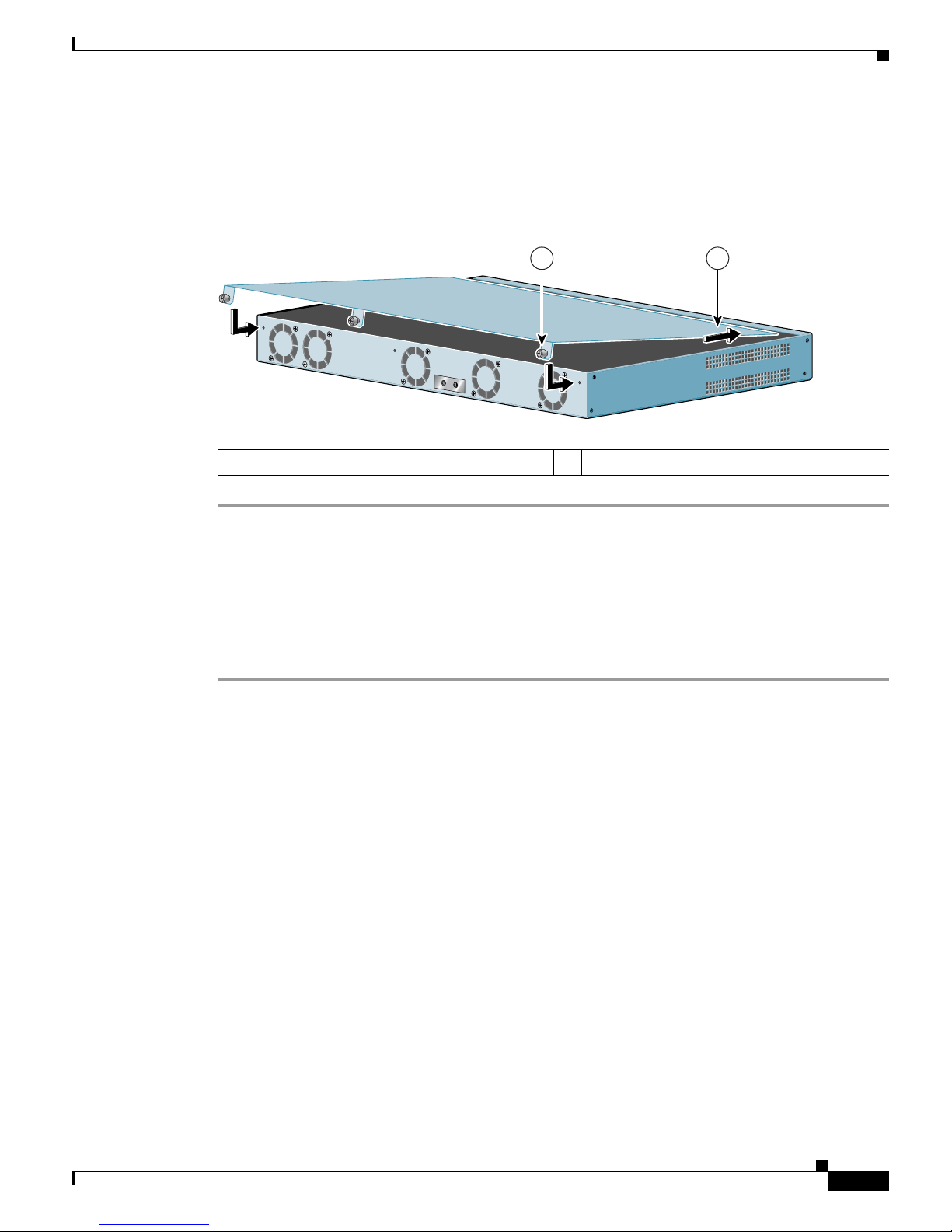
4-7
Cisco 7301 Installation and Configuration Guide
OL-5418-07
Chapter 4 Installing and Removing Field-Replaceable Units
Replacing the Cover and Powering On the Router
Replacing the Cover and Powering On the Router
The Cisco 7301 router cover fits tightly on the chassis. Follow these instructions to replace the cover:
Figure 4-5 Inserting the Screws and Replacing the Cover
Step 1 Holding the cover by the edge with the captive installation screws, tilt the cover and insert the front edge
tabs into their slots under the lip on the top of the router.
Step 2 Lower the cover, align the captive installation screws with the chassis screw holes, and insert and tighten
the three screws with a Phillips screwdriver.
Step 3 Return the router to its installation site, and attach the grounding cable, and input/output and power
cables.
Step 4 Power on the router by turning the power switch to the on position.
1 Inserting the lid under the router lip 2 Captive installation screws
80905
12
Page 100

4-8
Cisco 7301 Installation and Configuration Guide
OL-5418-07
Chapter 4 Installing and Removing Field-Replaceable Units
Replacing the Cover and Powering On the Router
 Loading...