

Page 1
ADMINISTRATION
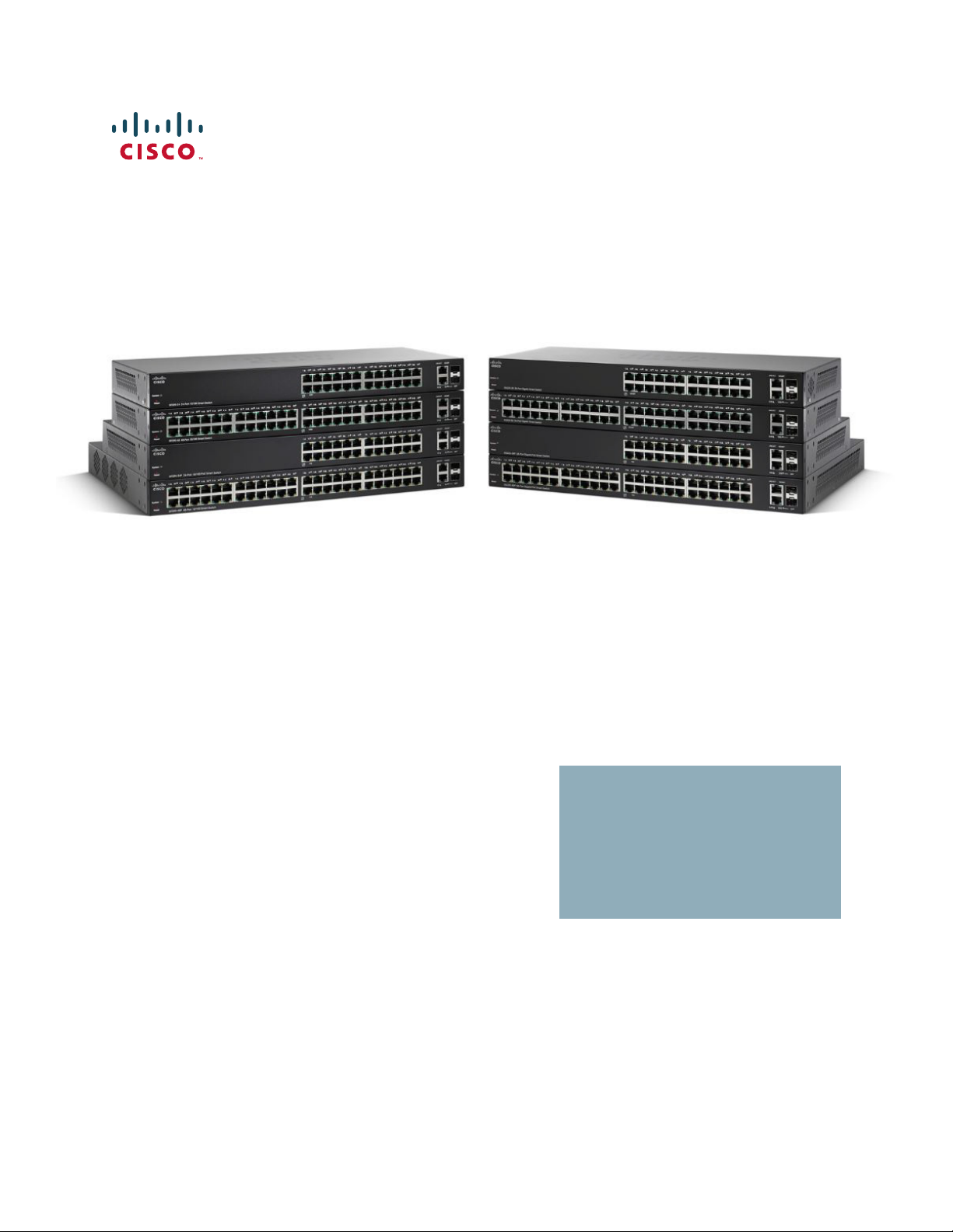
Cisco 220 Series Smart Switches
Administration Guide Release 1.1.0.x
July 21, 2017
GUIDE
Page 2

© 2016, 2017 Cisco Systems, Inc. All rights reserved.
Cisco and the Cisco logo are trademarks or registered trademarks of Cisco and/or its affiliates in the U.S. and other countries. To view a list of Cisco trademarks,
go to this URL: www.cisco.com/go/trademarks. Third-party trademarks mentioned are the property of their respective owners. The use of the word partner
does not imply a partnership relationship between Cisco and any other company. (1110R)
Page 3

Contents
Chapter 1: Getting Started 10
Getting Started with the Web-based Interface 10
Before You Begin 11
Logging In to the Web-based Interface 11
HTTP/HTTPS 12
Changing the Administrative Password 13
Logging Out 14
Quick Start Switch Configuration 15
Interface Naming Conventions 16
Window Navigation 17
Chapter 2: Status and Statistics 21
Viewing Ethernet Interface 21
Viewing Etherlike Statistics 23
Viewing TCAM Utilization 24
Viewing Fan Status and Temperature 25
Managing RMON 27
Viewing RMON Statistics 28
Configuring and Viewing RMON Histories 30
Configuring and Viewing RMON Events 32
Configuring RMON Alarms 34
Chapter 3: Administration: System Logs 37
Configuring System Log Settings 37
Configuring Remote Logging Settings 39
Viewing Memory Logs 39
Viewing RAM Memory Logs 40
Viewing Flash Memory Logs 41
Chapter 4: Administration: File Management 42
Files and File Types 42
Cisco 220 Series Smart Switches Administration Guide Release 1.1.0.x 1
Page 4

File Actions 44
Upgrade/Backup Firmware/Language 45
Active Image 48
Download/Backup Configuration or Logs 49
Configuration File Properties 51
Copy/Save Configuration Files 52
DHCP Auto Configuration 53
Contents
Chapter 5: Administration: General Information 58
Device Models 59
Viewing System Summary 61
Configuring System Settings 63
Configuring Console Settings 64
Rebooting the Switch 64
Defining Idle Session Timeout 65
Ping a Host 66
Using Traceroute 66
Chapter 6: Administration: Time Settings 68
System Time Options 69
Configuring System Time 69
Configuring SNTP Server 71
Time Range 72
Absolute Time Range 73
Periodic Time Range 73
Chapter 7: Administration: Diagnostics 75
Testing Copper Ports 75
Viewing Optical Module Status 76
Configuring Port and VLAN Mirroring 77
Cisco 220 Series Smart Switches Administration Guide Release 1.1.0.x 2
Page 5

Contents
Viewing CPU Utilization 80
Chapter 8: Administration: Discovery 81
Configuring Bonjour 81
LLDP and CDP 82
Configuring LLDP 83
Configuring LLDP Properties 85
Configuring LLDP Port Settings 86
Configuring LLDP MED Network Policy 87
Configuring LLDP MED Port Settings 89
Viewing LLDP Port Status 90
Viewing LLDP Local Information 91
Viewing LLDP Neighbors Information 94
Viewing LLDP Statistics 95
Viewing LLDP Overloading 95
Configuring CDP 98
Configuring CDP Properties 98
Configuring CDP Port Settings 100
Viewing CDP Local Information 101
Displaying CDP Neighbor Information 103
Viewing CDP Statistics 104
Chapter 9: Port Management 106
Port Management Workflow 106
Configuring Basic Port Settings 107
Configuring Error Recovery Settings 110
Loopback Detection 111
How LBD Works 112
Configuring Loopback Detection 112
Default Settings and Configuration 112
Interactions with Other Features 112
Configuring LBD Workflow 113
Cisco 220 Series Smart Switches Administration Guide Release 1.1.0.x 3
Page 6

To configure Loopback Detection: 113
Contents
Configuring Link Aggregation 114
Load Balancing 114
LAG Management 115
Static and Dynamic LAG Workflow 116
Configuring LAG Management 116
Configuring LAG Settings 117
Configuring LACP 119
Configuring Energy Efficient Ethernet 121
Chapter 10: Power over Ethernet 123
PoE Considerations 123
PoE on the Switch 124
Configuring PoE Properties 126
Configuring PoE Port Settings 128
Chapter 11: Managing VLANs 131
VLANs 131
Configuring Default VLAN 133
Creating VLANs 134
Configuring Interface’s VLAN Settings 135
Configuring Port to VLAN 137
Viewing VLAN Membership 138
Configuring GVRP 140
Configuring Voice VLAN 141
Configuring Voice VLAN Properties 143
Configuring Telephony OUI 143
Adding Interfaces to Voice VLAN on Basis of OUIs 145
Chapter 12: Spanning Tree Protocol 147
STP Modes 147
Cisco 220 Series Smart Switches Administration Guide Release 1.1.0.x 4
Page 7

Contents
Configuring STP Status and Global Settings 148
Configuring STP Interface Settings 150
Configuring RSTP Interface Settings 151
Configuring Multiple Spanning Tree 153
Configuring MSTP Properties 154
Mapping VLANs to MST Instance 155
Configuring MSTP Instance Settings 156
Configuring MSTP Interface Settings 156
Chapter 13: MAC Address Tables 159
Types of MAC Addresses 159
Configuring Static MAC Addresses 160
Configuring Static MAC Address Filter 161
Configuring Dynamic MAC Address Aging Time 161
Querying Dynamic MAC Addresses 162
Configuring Reserved MAC Addresses 163
Chapter 14: Multicast Forwarding 164
Multicast Forwarding 164
Configuring Multicast Properties 167
Configuring IP Multicast Group Addresses 168
Configuring IGMP Snooping 169
Configuring MLD Snooping 171
Querying IGMP/MLD IP Multicast Groups 173
Configuring Multicast Router Ports 174
Configuring Forward All Multicast 175
Configuring Maximum IGMP and MLD Groups 176
Configuring Multicast Filtering 176
Configuring Multicast Filter Profiles 177
Configuring Interface Filter Settings 177
Cisco 220 Series Smart Switches Administration Guide Release 1.1.0.x 5
Page 8

Contents
Chapter 15: IP Configuration 179
IP Addressing 179
IPv4 Management and Interface 181
IPv6 Management and Interface 182
Configuring Domain Name System 183
Configuring General DNS Settings 184
Viewing Static and Dynamic DNS Servers 185
Configuring Host Mapping 185
Chapter 16: Configuring Security 187
Configuring Users 188
Configuring TACACS+ Servers 189
Configuring RADIUS Servers 191
Configuring Management Access Methods 193
Access Profile Rules, Filters, and Elements 193
Active Access Profile 194
Configuring Access Profiles 194
Configuring Profile Rules 196
Configuring Password Complexity Rules 198
Configuring Management Access Authentication 200
Configuring TCP/UDP Services 201
Configuring Storm Control 203
Configuring Port Security 205
Configuring 802.1X 207
802.1X Parameters Workflow 208
Defining 802.1X Properties 209
Defining 802.1X Port Authentication 209
Defining Host and Session Authentication 212
Viewing Authenticated Hosts 213
Configuring DoS Protection 214
Secure Core Technology (SCT) 214
Cisco 220 Series Smart Switches Administration Guide Release 1.1.0.x 6
Page 9

Default Configuration 214
Configuring DoS Security Suite Settings 215
Configuring DoS Interface Settings 216
Configuring SYN Protection 217
Contents
Configuring DHCP Snooping 218
Configuring DHCP Snooping Properties 219
Configuring DHCP Snooping on VLANs 220
Configuring DHCP Snooping Trusted Interfaces 220
Querying DHCP Snooping Binding Database 221
Viewing Option 82 Statistics 222
Configuring Option 82 Interface Settings 223
Configuring Option 82 Port CID Settings 223
Configuring IP Source Guard 224
Configuring IP Source Guard Interface Settings 224
Querying IP Source Binding Database 225
Configuring Dynamic ARP Inspection 226
ARP Cache Poisoning 227
How ARP Prevents Cache Poisoning 227
Interaction Between ARP Inspection and DHCP Snooping 228
Workflow to Configure ARP Inspection 228
Configuring ARP Inspection Properties 229
Configuring ARP Inspection Trusted Interfaces 230
Viewing ARP Inspection Statistics 231
Configuring ARP Inspection VLAN Settings 231
Chapter 17: Access Control 233
Access Control Lists 234
Configuring MAC-based ACLs 236
Configuring MAC-based ACEs 237
Configuring IPv4-based ACLs 239
Configuring IPv4-Based ACEs 240
Cisco 220 Series Smart Switches Administration Guide Release 1.1.0.x 7
Page 10

Contents
Configuring IPv6-based ACLs 243
Configuring IPv6-based ACEs 243
Configuring ACL Binding 246
Chapter 18: Quality of Service 248
QoS Features and Components 248
Workflow to Configure QoS Settings 250
Configuring QoS Properties 251
Configuring QoS Queues 252
Mapping CoS/802.1p to a Queue 253
Mapping IP Precedence to Queue 255
Mapping DSCP to Queue 255
Mapping Queues to CoS/802.1p 256
Mapping Queue to IP Precedence 256
Mapping Queue to DSCP 257
Configuring Interface Remark 257
Configuring Bandwidth 258
Configuring Egress Shaping per Queue 258
Configuring VLAN Rate Limit 259
Configuring VLAN Port Rate Limit 260
Configuring TCP Congestion Avoidance 261
Configuring QoS Basic Mode 261
Configuring Basic QoS Trust Mode 262
Configuring Basic QoS Interface Settings 263
Configuring QoS Advanced Mode 263
Configuring Advanced QoS Global Settings 265
Configuring Class Mapping 266
QoS Policers 267
Configuring Aggregate Policers 268
Configuring QoS Policies 269
Configuring Policy Class Maps 270
Configuring Policy Binding 271
Cisco 220 Series Smart Switches Administration Guide Release 1.1.0.x 8
Page 11

Contents
Chapter 19: SNMP 272
SNMP Versions and Workflow 272
Supported MIBs 275
Model Object IDs 276
Configuring SNMP Engine ID 276
Configuring SNMP Views 278
Configuring SNMP Groups 279
Managing SNMP Users 280
Configuring SNMP Communities 282
Configuring SNMP Notification Recipients 283
Configuring SNMPv1,2 Notification Recipients 284
Configuring SNMPv3 Notification Recipients 285
Appendix A: Where to Go From Here 287
Cisco 220 Series Smart Switches Administration Guide Release 1.1.0.x 9
Page 12

Getting Started
This chapter provides an introduction to the web-based interface of the Cisco 220
switch and includes the following topics:
• Getting Started with the Web-based Interface
• Quick Start Switch Configuration
• Interface Naming Conventions
• Window Navigation
Getting Started with the Web-based Interface
1
The Cisco 220 switch can be accessed and managed by two methods; over your
IP network by using the web-based interface, or by using the command-line
interface through the console interface. Using the console interface requires
advanced user skills. See the
Interface Reference Guide
This section includes the following topics:
• Before You Begin
• Logging In to the Web-based Interface
• HTTP/HTTPS
• Changing the Administrative Password
• Logging Out
Cisco 220 Series Smart Switches Command Line
for more information about using the console interface.
Cisco 220 Series Smart Switches Administration Guide Release 1.1.0.x 10
Page 13

Getting Started
Getting Started with the Web-based Interface
Before You Begin
Before you begin to use the web-based interface, make sure that you have a
computer with Internet Explorer 8.0 (or higher), Firefox 20.0 (or higher), Chrome
23.0 (or higher), or Safari 5.7 (or higher).
These are the default settings used when configuring your switch for the first time:
Parameter Default Value
Username cisco
Password cisco
Switch IP 192.168.1.254
1
Logging In to the Web-based Interface
To access the switch with the web-based interface, you must know the IP address
that the switch is using. The default configuration of the switch is to use its factory
default IP address of 192.168.1.254 until it has obtained an IP address from a
DHCP server.
NOTE If you are managing the switch through a network connection and the switch IP
address is changed, either by a DHCP server or manually, your access to the switch
will be lost. You must enter the new IP address that the switch is using into your
browser to use the web-based interface. If you are managing the switch through a
console port connection, the link is retained.
To configure the switch using the web-based interface:
STEP 1 Power on the computer and your switch.
STEP 2 Connect the computer to the switch.
You can connect to the same IP subnet as the switch by connecting them directly
with an Ethernet cable, or by connecting to the same LAN where the switch is
located through other switches. You can also connect your computer to the switch
from another IP subnet through one or more IP routers.
STEP 3 Locate the IP address of the switch.
a. The switch can be accessed and managed by Cisco network tools and
services including the Cisco FindIT Network Discovery Utility which enables
you to automatically discover all supported Cisco devices in the same local
network segment as your computer. You can get a snapshot view of each
Cisco 220 Series Smart Switches Administration Guide Release 1.1.0.x 11
Page 14

Getting Started
Getting Started with the Web-based Interface
device or launch the product configuration utility to view and configure the
settings. For more information about FindIT, see www.cisco.com/go/findit.
b. Locate the IP address assigned by your DHCP server by accessing your router
or DHCP server; see your DHCP server instructions for information. Make sure
that your DHCP server is running and can be reached.
STEP 4 Set up the IP configuration on your computer.
• If the switch is using the default static IP address of 192.168.1.254, you
must choose an IP address in the range of 192.168.1.2 to 192.168.1.253 that
is not already in use.
• If the IP addresses will be assigned by DHCP, make sure that your DHCP
server is running and can be reached from the switch and the computer. You
may need to disconnect and reconnect the devices for them to discover their
new IP addresses from the DHCP server.
1
NOTE Details on how to change the IP address on your computer depend upon the
type of architecture and operating system that you are using. Use your computers
local Help and Support functionality and search for “IP Addressing.”
STEP 5 Open a web browser window. If you are prompted to install an Active-X plug-in
when connecting to the switch, follow the prompts to accept the plug-in.
STEP 6 Enter the IP address of the switch that you are configuring in the address bar on
the browser, and then press Enter. For example, http://192.168.1.254.
STEP 7 When the login page appears, choose the language that you prefer to use in the
web-based interface and enter the username and password.
The default username is cisco and the default password is cisco. Both username
and password are case sensitive.
STEP 8 Click Log In.
The first time that you log in with the default username and password, you are
required to enter a new password. The Change Password page opens.
HTTP/HTTPS
You can either open an HTTP session (not secured) by clicking Log In, or you can
open an HTTPS (secured) session by clicking Secure Browsing (HTTPS). You are
asked to approve the logon with a default RSA key, and an HTTPS session is
opened.
Cisco 220 Series Smart Switches Administration Guide Release 1.1.0.x 12
Page 15

Getting Started
Getting Started with the Web-based Interface
NOTE You do not need to input the username or password before clicking Secure
Browsing (HTTPS).
Changing the Administrative Password
For security purposes, you are required to change the administrative password at
your first login or when the current administrative password expires.
Password complexity is enabled by default. The minimum password complexity
requirements are shown on the page. The new password must comply with the
default complexity rules, or it can be disabled temporarily by selecting Disable
Password Strength Enforcement. See the Configuring Password Complexity
Rules section for more details about password complexity.
To change the password:
1
STEP 1 Enter the following fields to set a new administrative password:
• Old Password—Enter the current password (default is cisco).
• Password—Enter a new password.
• Confirm Password—Enter the new password again for confirmation.
• Password Strength Meter—Displays the strength of the new password.
• Disable Password Strength Enforcement—The password strength
enforcement enabled by default requires the password to conform to the
following default settings:
- Is different from the current username.
- Has a minimum length of eight characters.
- Contains characters from at least three character classes (uppercase
letters, lowercase letters, numbers, and special characters available on a
standard keyboard).
NOTE If you do not want to change the password, check Disable Password
Strength Enforcement and click Apply.
STEP 2 Click Apply.
Cisco 220 Series Smart Switches Administration Guide Release 1.1.0.x 13
Page 16

Getting Started
!
Getting Started with the Web-based Interface
The Getting Started page opens. You are now ready to configure the switch.
STEP 3 Check Do not show this page on startup to prevent the Getting Started page
from being displayed each time that you log on to the switch. If you select this
option, the System Summary page is opened instead of the Getting Started page.
Logging Out
By default, the application logs out after ten minutes of inactivity. You can change
this default value as described in the Defining Idle Session Timeout section.
CAUTION Unless the Running Configuration is copied to the Startup Configuration, all
changes made since the last time the file was saved are lost if the switch is
rebooted. Save the Running Configuration to the Startup Configuration before
logging off to preserve any changes that you made during this session.
1
A red X icon displayed to the left of the Save application link indicates that Running
Configuration changes that have been made have not yet been saved to the Startup
Configuration file. The flashing red X can be displayed by clicking the Disable Save
Icon Blinking button on the Copy/Save Configuration page.
When the switch auto-discovers a device, such as an IP phone, it configures the
port appropriately for the device. These configuration commands are written to the
Running Configuration file. This operation causes the Save icon to begin blinking
when the user logs on even though the user did not make any configuration
changes.
When you click Save, the Copy/Save Configuration page is displayed. Save the
Running Configuration file by copying it to the Startup Configuration file. After this
save, the red X icon and the Save application link are no longer displayed.
To l o g o u t , c l i c k Logout at the top right corner of any page. The system logs out of
the switch.
When a timeout occurs or you intentionally log out of the switch, a message is
displayed and the login page opens with a message indicating the logged-out
state. After you log in, the application returns to the initial page.
Cisco 220 Series Smart Switches Administration Guide Release 1.1.0.x 14
Page 17

Getting Started
Quick Start Switch Configuration
The initial page displayed depends on the “Do not show this page on startup”
option on the Getting Started page. If you did not select this option, the initial page
is the Getting Started page. If you did select this option, the initial page is the
System Summary page.
Quick Start Switch Configuration
To simplify switch configuration through quick navigation, the Getting Started
page provides links to the most commonly used pages.
Category Link Name (on the Page) Linked Page
1
Initial
Setup
Device
Status
Change Management
Applications and Services
Change Device IP Address Administration > Management
Create VLAN VLAN Management > Create
Configure Port Settings Port Management > Port Setting
System Summary Status and Statistics > System
Port Statistics Status and Statistics > Interface
RMON Statistics Status and Statistics > RMON >
View Log Status and Statistics > View Log >
Security > TCP/UDP Services
page
Interface > IPv4 Interface page
VLAN page
page
Summary page
page
Statistics page
RAM Memory page
Cisco 220 Series Smart Switches Administration Guide Release 1.1.0.x 15
Page 18

Getting Started
Interface Naming Conventions
1
Category Link Name (on the Page) Linked Page
Quick
Access
Change Device Password Administration > User Accounts
page
Upgrade Device Software Administration > File Management
> Upgrade/Backup Firmware/
Language page
Backup Device
Configuration
Create MAC-Based ACL Access Control > MAC-Based ACL
Create IP-Based ACL Access Control > IPv4-Based ACL
Configure QoS Quality of Service > General >
Configure Port Mirroring Administration > Diagnostics >
Administration > File Management
> Download/Backup
Configuration/Log page
page
page
QoS Properties page
Port and VLAN Mirroring page
There are two hot links on the Getting Started page that take you to Cisco web
pages for more information. Clicking on the Support link takes you to the device
product support page, and clicking on the Forums link takes you to the Cisco
Support Community page.
Interface Naming Conventions
Within the web-based interface, interfaces are denoted by concatenating the
following elements:
• Type of interface—The following types of interfaces are found on the
various types of devices:
- Fast Ethernet (10/100 bits)—These are displayed as FE.
- Gigabit Ethernet (10/100/1000 bits)—These are displayed as GE.
- LAG (Port Channel)—These are displayed as LAG.
- VLAN—These are displayed as VLAN.
Cisco 220 Series Smart Switches Administration Guide Release 1.1.0.x 16
Page 19

Getting Started
Window Navigation
- Tunnel —These are displayed as Tunnel.
• Interface Number—Port, LAG, tunnel, or VLAN ID.
Window Navigation
This section describes the features of the web-based interface.
Application Header
The Application Header appears on every page. It provides the following
application links:
1
Application Link
Name
Username Displays the name of the user logged on to the switch.
Language Menu
Logout Click to log out of the web-based interface.
About Click to display the switch name and device version
Description
The default username is cisco. (The default password
is cisco)
This menu provides the following options:
• Select a language: Select one of the languages
that appear in the menu. This language will be
the web-based interface language.
• Download Language: Add a new language to
the switch. To upgrade a language file, use the
Upgrade/Backup Firmware/Language page.
• Delete Language: Deletes the second
language on the switch. The first language
(English) cannot be deleted.
number.
Help Click to display the online help.
Cisco 220 Series Smart Switches Administration Guide Release 1.1.0.x 17
Page 20

Getting Started
Window Navigation
1
Application Link
Name
Alert The SYSLOG Alert Status icon appears when a
Save A flashing red X icon displayed to the left of the Save
Description
SYSLOG message, above the critical severity level, is
logged. Click the icon to open the RAM Memory page.
After you access this page, the SYSLOG Alert Status
icon is no longer displayed. To display the page when
there is not an active SYSLOG message, click Status
and Statistics > View Log > RAM Memory.
application link indicates that Running Configuration
changes have been made have not yet been saved to
the Startup Configuration file. The flashing of the red X
can be disabled on the Copy/Save Configuration page.
Click Save to display the Copy/Save Configuration
page. Save the Running Configuration file by copying it
to the Startup Configuration file type on the switch.
After this save, the red X icon and the Save application
link are no longer displayed. When the switch is
rebooted, it copies the Startup Configuration to the
Running Configuration and sets the switch parameters
according to the data in the Running Configuration.
Management Buttons
The following table describes the commonly-used buttons that appear on various
pages in the system.
Button Name Description
Add Click to display the related Add page and add an entry
to a table. Enter the information and click Apply to save
it to the Running Configuration. Click Close to return to
the main page. Click Save to display the Copy/Save
Configuration page and save the Running
Configuration to the Startup Configuration file type on
the switch.
Cisco 220 Series Smart Switches Administration Guide Release 1.1.0.x 18
Page 21

Getting Started
Window Navigation
1
Button Name Description
Apply Click to apply the changes to the Running
Configuration on the switch. If the switch is rebooted,
the Running Configuration is lost, unless it is saved to
the Startup Configuration file type or another file type.
Click Save to display the Copy/Save Configuration
page and save the Running Configuration to the
Startup Configuration file type on the switch.
Cancel Click to reset the changes made on the page.
Clear All Interfaces
Counters
Clear Interface
Counters
Clear Logs Clears log files.
Clear Table Clears table entries.
Close Returns to the main page. If any changes were not
Copper Test Click Copper Test to perform the related test.
Copy Settings A table typically contains one or more entries
Click to clear the statistics counters for all interfaces.
Click to clear the statistics counters for the selected
interface.
applied to the Running Configuration, a message
appears.
containing configuration settings. Instead of modifying
each entry individually, it is possible to modify one
entry and then copy the selected entry to multiple
entries, as described here:
1. Select the entry to be copied and click Copy
Settings.
2. Enter the destination entry numbers in the to field.
3. Click Apply to save the changes and click Close to
return to the main page.
Delete After selecting an entry in the table, click Delete to
remove.
Details Click to display the details associated with the entry
selected.
Cisco 220 Series Smart Switches Administration Guide Release 1.1.0.x 19
Page 22

Getting Started
Window Navigation
1
Button Name Description
Edit Select the entry and click Edit. The Edit page appears,
and the entry can be modified.
1. C li ck Apply to save the changes to the Running
Configuration.
2. Click Close to return to the main page.
Go Enter the query filtering criteria and click Go. The
results are displayed on the page.
Refresh Click to manually refresh the data on the page.
View All Interfaces
Statistics
View Interface
Statistics
Click to see the statistics counters for all interfaces on
a single page.
Click to see the statistics counters for the selected
interface on a single page.
Cisco 220 Series Smart Switches Administration Guide Release 1.1.0.x 20
Page 23

Status and Statistics
This chapter describes how to view switch statistics, and includes the following
topics:
• Viewing Ethernet Interface
• Viewing Etherlike Statistics
• Viewing TCAM Utilization
• Viewing Fan Status and Temperature
• Managing RMON
2
Viewing Ethernet Interface
The Interface page displays traffic statistics per interface. The refresh rate of the
information can be selected. This page is useful for analyzing the amount of traffic
that is both sent and received and its dispersion (Unicast, Multicast, and
Broadcast).
To view Ethernet statistics and/or set the refresh rate:
STEP 1 Click Status and Statistics > Interface.
STEP 2 Enter the following information:
• Interface—Select the port or LAG for which the Ethernet statistics are
displayed.
• Refresh Rate—Select the time period that passes before the Ethernet
statistics are refreshed. The available options are:
No Refresh
-
-
15 sec
—Statistics are refreshed every 15 seconds.
—Statistics are not refreshed.
30 sec
-
Cisco 220 Series Smart Switches Administration Guide Release 1.1.0.x 21
—Statistics are refreshed every 30 seconds.
Page 24

Status and Statistics
Viewing Ethernet Interface
2
-
60 sec
The Receive Statistics area displays the following fields about incoming packets:
• Tot al B y tes (O ct ets )—Octets received, including bad packets and FCS
octets, but excluding framing bits.
• Unicast Packets—Good Unicast packets received.
• Multicast Packets—Good Multicast packets received.
• Broadcast Packets—Good Broadcast packets received.
• Packets with Errors—Packets with errors received.
The Transmit Statistics area displays the following fields about outgoing packets:
• Tot al B y tes (O ct ets )—Octets transmitted, including bad packets and FCS
octets, but excluding framing bits.
—Statistics are refreshed every 60 seconds.
• Unicast Packets—Good Unicast packets transmitted.
• Multicast Packets—Good Multicast packets transmitted.
• Broadcast Packets—Good Broadcast packets transmitted.
STEP 3 Click Clear Interface Counters to clear the statistics counters for the selected
interface.
STEP 4 Click Refresh to manually refresh the statistics counters for the selected interface.
STEP 5 Click View All Interfaces Statistics to see the statistics counters for all interfaces
on a single page. The Interface Statistics Table displays the statistics counters for
all interfaces. From this page you can perform the following actions:
• Select the refresh rate from the Refresh Rate drop-down menu.
• Select an interface and click Clear Interface Counters to clear the statistics
counters for the selected interface.
• Click Clear All Interface Counters to clear the statistics counters for all
interfaces.
• Select an interface and click View Interface Statistics to see the statistics
counters for the selected interface on a single page.
• Click Refresh to manually refresh the statistics counters for all interfaces.
Cisco 220 Series Smart Switches Administration Guide Release 1.1.0.x 22
Page 25

Status and Statistics
Viewing Etherlike Statistics
Viewing Etherlike Statistics
The Etherlike page displays statistics per interface according to the Etherlike MIB
standard definition. The refresh rate of the information can be selected. This page
provides more detailed information regarding errors in the physical layer (Layer 1),
which might disrupt traffic.
To view Etherlike statistics and/or set the refresh rate:
STEP 1 Click Status and Statistics > Etherlike.
STEP 2 Enter the following information:
• Interface—Select the port or LAG for which the Etherlike statistics are
displayed.
2
• Refresh Rate—Select the time period that passes before the Etherlike
statistics are refreshed.
The following fields are displayed for the selected interface:
• Frame Check Sequence (FCS) Errors—Number of received frames that
failed the Cyclic Redundancy Checks (CRC).
• Single Collision Frames—Number of frames involved in a single collision,
but were successfully transmitted.
• Late Collisions—Number of collisions that have been detected after the first
512 bits of data.
• Excessive Collisions—Number of transmissions due to excessive collisions.
• Oversize Packets—Number of packets greater than 1518 octets received.
• Internal MAC Receive Errors—Number of frames rejected because of
receiver errors.
• Pause Frames Received—Number of received flow control pause frames.
• Pause Frames Transmitted—Number of flow control pause frames
transmitted from the selected interface.
STEP 3 Click Clear Interface Counters to clear the statistics counters for the selected
interface.
STEP 4 Click Refresh to manually refresh the statistics counters for the selected interface.
Cisco 220 Series Smart Switches Administration Guide Release 1.1.0.x 23
Page 26

Status and Statistics
Viewing TCAM Utilization
STEP 5 Click View All Interfaces Statistics to see the statistics counters for all interfaces
2
on a single page. The Etherlike Statistics Table displays the statistics counters for
all interfaces. From this page you can perform the following actions:
• Select the refresh rate from the Refresh Rate drop-down menu.
• Select an interface and click Clear Interface Counters to clear the statistics
counters for the selected interface.
• Click Clear All Interface Counters to clear the statistics counters for all
interfaces.
• Select an interface and click View Interface Statistics to see the statistics
counters for the selected interface on a single page.
• Click Refresh to manually refresh the statistics counters for all interfaces.
Viewing TCAM Utilization
The switch architecture uses a Ternary Content Addressable Memory (TCAM) to
support packet actions in wire speed. TCAM holds the rules produced by
applications (such as ACL and QoS) and the system-created rules.
Only system application allocates rules upon its initiation.
To view TCAM utilization, click Status and Statistics > TCAM Utilization.
The following fields are displayed:
• Maximum TCAM Entries—Maximum TCAM entries available.
• In Use—Number of TCAM entries that are currently using.
Cisco 220 Series Smart Switches Administration Guide Release 1.1.0.x 24
Page 27

Status and Statistics
Viewing Fan Status and Temperature
Viewing Fan Status and Temperature
The Fan and Thermal Status page displays the fan and temperature status of the
switches with PoE capabilities.
The following table lists the number of fan channels and temperature channels
applicable on different PoE switch models:
2
Model Number of Fan
Channels
SF220-24P 2 2
SF220-48P 4 2
SG220-26P 2 2
SG220-28MP 3 2
SG220-50P 4 2
To view the fan and temperature status, click Status and Statistics > Fan and
Thermal Status.
The following fields are displayed:
x
• FAN
-
-
Status—Displays the operation status of the switch fans.
Operational Status
displays Fault if the fan does not operate normally.
Speed Value
—Displays OK if the fan operates normally, or
—Displays the fan speed in revolutions per minute (RPM).
Number of Temperature
Channels
x
• Thermal
Operational Status
-
or displays Fault when the thermal does not operate normally.
-
Temperature Value
Cisco 220 Series Smart Switches Administration Guide Release 1.1.0.x 25
Status—Displays the status of the switch thermals.
—Displays OK when the thermal operates normally,
—Displays the current temperature in Celsius.
Page 28

Status and Statistics
Viewing Fan Status and Temperature
-
Temperature Status
possible values are:
Green—Indicates that the current temperature is lower than the yellow
threshold.
Yellow—Indicates that the current temperature is greater than the
yellow threshold, but lower than the red threshold.
Red—Indicates that the current temperature is greater than the red
threshold.
—Displays the current temperature status. The
2
Yellow Threshold
-
temperature thermal.
-
Red Threshold
thermal.
The following table lists the yellow and red threshold values for two thermals
applicable on different PoE switch models:
Model Yellow
Threshold of
Thermal 1
SF220-24P 158
SF220-26P 203
SF220-28MP 167
SF220-48P 147
SF220-50P 158
—Displays the yellow threshold value of the
—Displays the red threshold value of the temperature
Red
Threshold of
Thermal 1
°F (70°C) 167°F (75°C) 171°F (77°C) 180°F (82°C)
°F (95°C) 210°F (99°C) 178°F (81°C) 185°F (85°C)
°F (75°C) 176°F (80°C) 152°F (67°C) 162°F (72°C)
°F (64°C) 156°F (69°C) 156°F (69°C) 165°F (74°C)
°F (70°C) 167°F (75°C) 167°F (75°C) 176°F (80°C)
Yel lo w
Threshold of
Thermal 2
Red
Threshold of
Thermal 2
Cisco 220 Series Smart Switches Administration Guide Release 1.1.0.x 26
Page 29

Status and Statistics
Managing RMON
Managing RMON
Remote Networking Monitoring (RMON) is an SNMP specification that enables an
SNMP agent in the switch to proactively monitor traffic statistics over a given
period and send traps to an SNMP manager. The local SNMP agent compares
actual, real-time counters against predefined thresholds and generates alarms,
without the need for polling by a central SNMP management platform. This is an
effective mechanism for proactive management, provided that you have right
thresholds set relative to your network’s base line.
RMON decreases the traffic between the manager and the switch because the
SNMP manager does not have to frequently poll the switch for information, and
enables the manager to get timely status reports because the switch reports
events as they occur.
With this feature, you can perform the following actions:
2
• View the current statistics (since the counter values were cleared). You can
also collect the values of these counters over a period of time, and then
view the table of collected data, where each collected set is a single line of
the History Table.
• Define interesting changes in counter values, such as “reached a certain
number of late collisions” (defines the alarm), and then specify what action
to perform when this event occurs (log, trap, or log and trap).
NOTE For RMON configuration to be effective, make sure that the SNMP service is
enabled on the switch.
This section includes the following topics:
• Viewing RMON Statistics
• Configuring and Viewing RMON Histories
• Configuring and Viewing RMON Events
• Configuring RMON Alarms
Cisco 220 Series Smart Switches Administration Guide Release 1.1.0.x 27
Page 30

Status and Statistics
Managing RMON
2
Viewing RMON Statistics
The Statistics page displays detailed information regarding packet sizes and
some information regarding physical layer errors. The information shown is
according to the RMON standard. An oversized packet is defined as an Ethernet
frame with the following criteria:
• Packet length is greater than MRU byte size.
• Collision event has not been detected.
• Late collision event has not been detected.
• Received (Rx) error event has not been detected.
• Packet has a valid CRC.
To view RMON statistics and/or set the refresh rate:
STEP 1 Click Status and Statistics > RMON > Statistics.
STEP 2 Enter the following information:
• Interface—Select the port or LAG for which RMON statistics are displayed.
• Refresh Rate—Select the time period that passes before RMON statistics
are refreshed.
The following fields are displayed for the selected interface:
• RMON Received Bytes (Octets)—Number of octets received, including
bad packets and FCS octets, but excluding framing bits.
• RMON Drop Events—Number of packets that were dropped.
• RMON Received Packets —Number of packets received, including bad
packets, Multicast packets, and Broadcast packets.
• RMON Broadcast Packets Received—Number of good Broadcast packets
received. This number does not include Multicast packets.
• RMON Multicast Packets Received—Number of good Multicast packets
received.
• RMON CRC & Align Errors—Number of CRC and Align errors that have
occurred.
• RMON Undersize Packets—Number of undersized packets (less than 64
octets) received.
Cisco 220 Series Smart Switches Administration Guide Release 1.1.0.x 28
Page 31

Status and Statistics
Managing RMON
2
• RMON Oversize Packets—Number of oversized packets (over 1518 octets)
received.
• RMON Fragments—Number of fragments (packets with less than 64 octets,
excluding framing bits, but including FCS octets) received.
• RMON Jabbers—Number of received packets that were longer than 1632
octets. This number excludes frame bits, but includes FCS octets that had
either a bad FCS (Frame Check Sequence) with an integral number of octets
(FCS Error) or a bad FCS with a non-integral octet (Alignment Error) number.
A Jabber packet is defined as an Ethernet frame that satisfies the following
criteria:
- Packet data length is greater than MRU.
- Packet has an invalid CRC.
- RX error event has not been detected.
• RMON Collisions—Number of collisions received. If Jumbo Frames are
enabled, the threshold of Jabber Frames is raised to the maximum size of
Jumbo Frames.
• Frames of 64 Bytes—Number of frames, containing 64 bytes that were
received.
• Frames of 65 to 127 Bytes—Number of frames, containing 65 to 127 bytes
that were received.
• Frames of 128 to 255 Bytes—Number of frames, containing 128 to 255
bytes that were received.
• Frames of 256 to 511 Bytes—Number of frames, containing 256 to 511
bytes that were received.
• Frames of 512 to 1023 Bytes—Number of frames, containing 512 to 1023
bytes that were received.
• Frames Greater than 1024 Bytes—Number of frames, containing 1024 to
2000 bytes, and Jumbo Frames, that were received.
STEP 3 Click Clear Interface Counters to clear RMON statistics counters for the selected
interface.
STEP 4 Click Refresh to manually refresh RMON statistics counters for the selected
interface.
STEP 5 Click View All Interfaces Statistics to view RMON statistics counters for all
interfaces on a single page. The RMON Statistics Table displays the RMON
Cisco 220 Series Smart Switches Administration Guide Release 1.1.0.x 29
Page 32

Status and Statistics
Managing RMON
2
statistics counters for all interfaces. From this page you can perform the following
actions:
• Select the refresh rate from the Refresh Rate drop-down menu.
• Select an interface and click Clear Interface Counters to clear RMON
statistics counters for the selected interface.
• Click Clear All Interfaces Counters to clear RMON statistics counters for all
interfaces.
• Select an interface and click View Interface Statistics to see RMON
statistics counters for the selected interface on a single page.
• Click Refresh to manually refresh RMON statistics counters for all interfaces.
Configuring and Viewing RMON Histories
RMON can be used to monitor statistics per interface. Use the History Control
Table page to define the sampling frequency, amount of samples to store, and the
interface from where to gather the data. After the data is sampled and stored, it
appears on the History Table page that can be viewed by clicking History Table.
Configuring RMON History Control Samples
To define RMON control sample:
STEP 1 Click Status and Statistics > RMON > History.
RMON is allowed by standard to not grant all requested samples, but rather to limit
the number of samples per request. The Current Number of Samples field
displays the sample number actually granted to the request that is equal or less
than the requested value.
STEP 2 Click Add to add a history control sample.
STEP 3 Enter the following information:
• New History Entry—Displays the number of the history entry.
• Source Interface—Select the port or LAG from where the history samples
are to be taken.
• Max No. of Samples to Keep—Enter the number of samples to store.
Cisco 220 Series Smart Switches Administration Guide Release 1.1.0.x 30
Page 33

Status and Statistics
Managing RMON
STEP 4 Click Apply. The RMON history control sample is added, and the Running
STEP 5 Click History Table to view the actual statistics.
2
• Interval—Enter the time in seconds that samples were collected from the
interface.
• Owner—Enter the RMON station or user that requested the RMON
information.
Configuration is updated.
Viewing RMON History Statistics
The History Table page displays interface-specific statistical network samplings.
The samples are configured in the History Control Table described in the previous
section.
To view RMON history statistics:
STEP 1 Click Status and Statistics > RMON > History.
STEP 2 Click History Table.
STEP 3 Select the entry number to display the samples associated with that history entry,
and click Go.
The following fields are displayed for the selected history sample:
• History Entry No.—Number of the history entry.
• Owner—History entry owner.
• Sample No.—Statistics were taken from this sample.
• Drop Events—Number of dropped packets due to lack of network
resources during the sampling interval. This field may not represent the
exact number of dropped packets, but rather the number of times that
dropped packets were detected.
• Bytes Received—Number of octets received including bad packets and
FCS octets, but excluding framing bits.
• Packets Received—Number of packets received, including bad packets,
Multicast, and Broadcast packets.
• Broadcast Packets—Number of good Broadcast packets received. This
number does not include Multicast packets.
Cisco 220 Series Smart Switches Administration Guide Release 1.1.0.x 31
Page 34

Status and Statistics
Managing RMON
2
• Multicast Packets—Number of good Multicast packets received.
• CRC & Align Errors—Number of CRC and align errors that have occurred.
• Undersize Packets—Number of undersized packets (less than 64 octets)
received.
• Oversize Packets—Number of oversized packets (over 1518 octets)
received.
• Fragments—Number of fragments (packets with less than 64 octets)
received, excluding framing bits, but including Frame Check Sequence
(FCS) octets.
• Jabbers—Number of received packets that were longer than 1632 octets.
This number excludes frame bits, but includes FCS octets that had either a
bad FCS with an integral number of octets (FCS Error) or a bad FCS with a
non-integral octet (Alignment Error) number.
• Collisions—Number of collisions received.
• Utilization—Percentage of current interface traffic compared to the
maximum traffic that the interface can handle.
STEP 4 Click History Control Table to return to the History Control Table page.
Configuring and Viewing RMON Events
You can control the occurrences that trigger an alarm and the type of notification
that occurs. This is performed as follows:
• Events Page—Configures what happens when an alarm is triggered. This
can be any combination of logs and traps.
• Alarms Page—Configures the occurrences that trigger an alarm.
Cisco 220 Series Smart Switches Administration Guide Release 1.1.0.x 32
Page 35

Status and Statistics
Managing RMON
STEP 1 Click Status and Statistics > RMON > Events.
STEP 2 Click Add to add an RMON event.
STEP 3 Enter the following information:
2
Configuring RMON Events
Use the Events page to configure events that are actions performed when an
alarm is generated (alarms are defined on the Alarms page). An event can be any
combination of logs and traps. If the action includes logging of the events, they are
displayed on the Event Log Table page.
To configure RMON events:
• Event Entry—Displays the number for the event entry.
• Community— Enter the SNMP community string to be included when traps
are sent.
• Description—Enter a name for the event. This name is used to attach an
alarm to an event.
• Notification Type—Select the type of action that results from this event.
The available options are:
None
-
-
-
-
• Owner—Enter the device or user that defined the event.
STEP 4 Click Apply. The RMON event is added, and the Running Configuration is updated.
STEP 5 Click Event Log Table to display the log of alarms that have occurred and that
have been logged.
—No action occurs when the alarm goes off.
Log (Event Log Table)
alarm goes off.
Tra p ( SN MP Man ag er )
Log and Trap
the remote log server when the alarm goes off.
—Add a log entry to the Event Log Table and send a trap to
—Add a log entry to the Event Log Table when the
—Send a trap when alarm goes off.
Cisco 220 Series Smart Switches Administration Guide Release 1.1.0.x 33
Page 36

Status and Statistics
Managing RMON
STEP 1 Click Status and Statistics > RMON > Events.
STEP 2 Click Event Log Table.
2
Viewing RMON Event Logs
The Event Log Table page displays the log of events (actions) that occurred. An
event can be logged when the type of the event is Log or Log and Trap. The action
in the event is performed when the event is bound to an alarm (see Configuring
RMON Alarms) and the conditions of the alarm have occurred.
To view RMON event logs:
The following fields are displayed:
• Event Entry No.—Number of the event’s log entry.
• Log No.—Log number (within the event).
• Log Time—Time that the log entry was entered.
• Description—Description of event that triggered the alarm.
STEP 3 Click Event Table to return to the Events page.
Configuring RMON Alarms
RMON alarms provide a mechanism for setting thresholds and sampling intervals
to generate exception events on any counter or any other SNMP object counter
maintained by the agent. Both the rising and falling thresholds must be configured
in the alarm. After a rising threshold is crossed, no rising events are generated until
the companion falling threshold is crossed. After a falling alarm is issued, the next
alarm is issued when a rising threshold is crossed.
One or more alarms are bound to an event, which indicates the action to be taken
when the alarm occurs.
Use the Alarms page to configure alarms and to bind them with events. Alarm
counters can be monitored by either absolute values or changes (delta) in the
counter values.
Cisco 220 Series Smart Switches Administration Guide Release 1.1.0.x 34
Page 37

Status and Statistics
Managing RMON
STEP 1 Click Status and Statistics > RMON > Alarms.
STEP 2 Click Add to add an RMON alarm.
STEP 3 Enter the following information:
2
To define RMON alarms:
• Alarm Entry—Displays the number of the alarm entry.
• Interface—Select a port or LAG.
• Counter Name—Select the MIB variable that indicates the type of
occurrence measured.
• Sample Type—Select the sampling method to generate an alarm. The
possible options are:
- Absolute—If the threshold is passed, an alarm is generated.
- Delta—Subtracts the last sampled value from the current value. The
difference in the values is compared to the threshold. If the threshold is
passed, an alarm is generated.
• Rising Threshold—Enter the rising counter value that triggers the rising
threshold alarm.
• Rising Event—Select an event, from those that you defined on the Events
page, to be performed when a rising event is triggered.
• Falling Threshold—Enter the falling counter value that triggers the falling
threshold alarm.
• Falling Event—Select an event, from those that you defined on the Events
page, to be performed when a falling event is triggered.
• Startup Alarm—Select the first event from which to start generation of
alarms. Rising is defined by crossing the threshold from a low-value
threshold to a higher-value threshold.
Rising Alarm
-
—A rising counter value triggers the rising threshold alarm.
Falling Alarm
-
Rising and Falling Alarm
-
the alarm.
• Interval—Enter the alarm interval time in seconds.
Cisco 220 Series Smart Switches Administration Guide Release 1.1.0.x 35
—A falling counter value triggers the falling threshold alarm.
—Both a rising and falling counter values trigger
Page 38

Status and Statistics
Managing RMON
STEP 4 Click Apply. The RMON alarm is added, and the Running Configuration is updated.
2
• Owner—Enter the name of the user or network management system that
receives the alarm.
Cisco 220 Series Smart Switches Administration Guide Release 1.1.0.x 36
Page 39

Administration: System Logs
This chapter describes the System Log feature, which enables the switch to keep
several independent logs. Each log is a set of messages recording system events.
The switch generates the following local logs:
• Log sent to the console interface.
• Log written into a cyclical list of logged events in RAM and is erased when
the switch reboots.
• Log written to a cyclical log file saved to flash memory and persists across
reboots.
In addition, you can send messages to remote SYSLOG servers in the form of
SYSLOG messages.
3
This chapter covers the following topics:
• Configuring System Log Settings
• Configuring Remote Logging Settings
• Viewing Memory Logs
Configuring System Log Settings
You can enable or disable logging on the switch and select the events to be
logged by severity level. The event severity levels are listed from the highest
severity to the lowest severity:
• Emergency—System is not usable.
• Alert—Immediate action is needed.
• Critical—System is in a critical condition.
• Error—System is in error condition.
Cisco 220 Series Smart Switches Administration Guide Release 1.1.0.x 37
Page 40

Administration: System Logs
Configuring System Log Settings
• Warning—System warning has occurred.
• Notice—System is functioning properly, but a system notice has occurred.
• Informational—Device information.
• Debug—Provides detailed information about an event.
You can select different severity levels for RAM and flash logs. These logs are
displayed on the RAM Memory page and Flash Memory page, respectively.
Selecting a severity level to be stored in a log causes all of the higher severity
events to be automatically stored in the log. Lower severity events are not stored
in the log. For example, if Warning is selected, all severity levels that are Warning
and higher are stored in the log (Emergency, Alert, Critical, Error, and Warning). No
events with severity level below Warning (Notice, Informational, and Debug) are
stored.
3
To configure global log parameters:
STEP 1 Click Administration > System Log > Log Settings.
STEP 2 Enter the following information:
• Logging—Check Enable to enable logging on the switch, or uncheck to
disable logging on the switch.
• RAM Memory Logging—Check Enable to enable RAM memory logging
and check the severity levels of the messages to be logged to RAM.
• Flash Memory Logging—Check Enable to enable flash memory logging
and check the severity levels of the messages to be logged to flash memory.
STEP 3 Click Apply. The global log settings are defined, and the Running Configuration is
updated.
Cisco 220 Series Smart Switches Administration Guide Release 1.1.0.x 38
Page 41

Administration: System Logs
Configuring Remote Logging Settings
Configuring Remote Logging Settings
Use the Remote Log Servers page to define the remote SYSLOG servers where
log messages are sent (using the SYSLOG protocol). For each server, you can
configure the severity of the messages that it receives.
To configure a remote SYSLOG server:
STEP 1 Click Administration > System Log > Remote Log Servers.
STEP 2 Click Add to add a remote SYSLOG server.
STEP 3 Enter the following information:
• Server Definition—Select whether to identify the remote log server by IP
address or name.
3
• IP Version—Select either Version 4 or Version 6 if the remote log server is
identified by IP address.
• Log Server IP Address/Name—Enter the IP address or hostname of the
remote log server.
• UDP Port—Enter the UDP port to which the log messages are sent.
• Facility—Select a facility from which system logs are sent to the remote
server. Only one facility can be assigned to a server.
• Minimum Severity—Select the minimum level of system log messages to
be sent to the server.
STEP 4 Click Apply. The remote SYSLOG server is added, and the Running Configuration
is updated.
Viewing Memory Logs
The switch can write to the following logs:
• Log in RAM (cleared during reboot). See Viewing RAM Memory Logs for
more information.
• Log in flash memory (cleared only upon user command). See Viewing Flash
Memory Logs for more information.
Cisco 220 Series Smart Switches Administration Guide Release 1.1.0.x 39
Page 42

Administration: System Logs
Viewing Memor y Logs
You can configure the messages that are written to each log by severity. A
message can go to more than one log, including logs that reside on external
SYSLOG servers.
Viewing RAM Memory Logs
The RAM Memory page displays all messages that are saved in RAM (cache) in
inverse-chronological order. Entries are stored in the RAM log according to the
configuration on the Log Settings page.
To view RAM logs:
STEP 1 Click Status and Statistics > View Log > RAM Memory.
The following fields are displayed:
3
• Log Index—Log entry number.
• Log Time—Time when message was generated.
• Severity—Event severity.
• Description—Message text describing the event.
STEP 2 Click Clear Logs to clear the log messages.
STEP 3 By default, the SYSLOG Alert Status icon appears and blinks when a SYSLOG
message above the critical severity level is logged. To disable this alert icon
blinking, click Disable Alert Icon Blinking. The SYSLOG Alert Status icon is no
longer displayed.
Cisco 220 Series Smart Switches Administration Guide Release 1.1.0.x 40
Page 43

Administration: System Logs
Viewing Memor y Logs
Viewing Flash Memory Logs
The Flash Memory page displays the messages that are stored in flash memory in
chronological order. The minimum severity for logging is configured on the Log
Settings page. Flash logs remain when the switch is rebooted. You can clear the
logs manually.
To view flash logs:
STEP 1 Click Status and Statistics > View Log > Flash Memory.
The following fields are displayed:
• Log Index—Log entry number.
• Log Time—Time when message was generated.
• Severity—Event severity.
3
• Description—Message text describing the event.
STEP 2 Click Clear Logs to clear the log messages.
Cisco 220 Series Smart Switches Administration Guide Release 1.1.0.x 41
Page 44

Administration: File Management
This chapter describes how system files are managed, such as upgrading system
firmware, rebooting the switch, restoring the switch to factory defaults, managing
the configuration files and log files, and so on.
It includes the following topics:
• Files and File Types
• File Actions
• Upgrade/Backup Firmware/Language
• Active Image
• Download/Backup Configuration or Logs
4
• Configuration File Properties
• Copy/Save Configuration Files
• DHCP Auto Configuration
Files and File Types
System files are files that contain configuration information or firmware images.
Various actions can be performed with these files:
• Selecting the firmware file from which the switch boots.
• Copying various types of configuration files internally on the switch.
• Copying files to or from an external device, such as an external server.
The possible methods of file transfer are:
• Internal copy.
Cisco 220 Series Smart Switches Administration Guide Release 1.1.0.x 42
Page 45

Administration: File Management
Files and File Types
• HTTP/HTTPS that uses the facility that the browser provides.
• TFTP client, requiring a TFTP server.
Configuration files on the switch are defined by their type, and contain the settings
and parameter values for the switch. When a configuration is referenced on the
switch, it is referenced by its configuration file type (such as Startup Configuration
or Running Configuration), instead of a file name that can be modified by the user.
Content can be copied from one file type to another, but the names of the file
types cannot be changed by the user. Other files on the switch include firmware
and log files, and are referred to as operational files.
Configuration files are text files that can be edited by a user in a text editor, such as
Notepad after they are copied to an external device, such as a PC.
The following types of configuration and operational files are found on the switch:
• Running Configuration—Contains parameters that are currently used by
the switch to operate. It is the only file type that is modified when you
change the parameter values on the switch.
4
If the switch is rebooted, the Running Configuration is lost. When the switch
is rebooted, this file type is copied from the Startup Configuration stored in
flash to the Running Configuration stored in RAM.
To preserve any changes that you made to the switch, you must save the
Running Configuration to the Startup Configuration, or another file type if
you do not want the switch to reboot with this configuration. If you have
saved the Running Configuration to the Startup Configuration, when the
switch is rebooted, it recreates a Running Configuration that includes the
changes made since the last time that the Running Configuration was saved
to the Startup Configuration.
• Startup Configuration—The parameter values that were saved by you by
copying another configuration (usually the Running Configuration) to the
Startup Configuration.
The Startup Configuration is retained in flash and is preserved when the
switch is rebooted. At this time, the Startup Configuration is copied to RAM
and identified as the Running Configuration.
• Backup Configuration—A manual copy of the parameter definitions for
protection against system shutdown or for the maintenance of a specific
operating state. You can copy the Mirror Configuration, Startup
Configuration, or Running Configuration to the Backup Configuration. The
Backup Configuration exists in flash and is preserved if the switch is
rebooted.
Cisco 220 Series Smart Switches Administration Guide Release 1.1.0.x 43
Page 46

Administration: File Management
File Actions
• Mirror Configuration—A copy of the Startup Configuration, created by the
switch when the following conditions exist:
- The switch has been operating continuously for 24 hours.
- No configuration changes have been made to the Running Configuration
- The Startup Configuration is identical to the Running configuration.
Only the system can copy the Startup Configuration to the Mirror
Configuration. However, you can copy from the Mirror Configuration to other
file types or to another device.
If the switch is rebooted, the Mirror Configuration is reset to the factory
default parameters. In all other aspects, the Mirror Configuration functions
the same as a Backup Configuration, providing a copy of the parameter
values that is preserved if the switch is rebooted.
4
in the previous 24 hours.
File Actions
• Firmware—The program that controls the operations and functionality of
the switch. More commonly referred to as the image.
• Language File—The dictionary that enables the web-based interface to be
displayed in the selected language.
•
Flash Logs
The following actions can be performed to manage firmware, configuration files,
and logs:
• Upgrade the firmware image, replace a second language file, or back up
the firmware as described in Upgrade/Backup Firmware/Language
section.
• View the firmware image currently in use or select the image to be used in
the next reboot as described in the Active Image section.
• Save configuration files on the switch to a location on another device as
described in the Download/Backup Configuration or Logs section.
—SYSLOG messages stored in flash memory.
• Clear the Startup Configuration or Backup Configuration file types as
described in the Configuration File Properties section.
Cisco 220 Series Smart Switches Administration Guide Release 1.1.0.x 44
Page 47

Administration: File Management
!
Upgrade/Backup Firmware/Language
• Copy one configuration file type to another configuration file type as
described in the Copy/Save Configuration Files section.
• Automatically download a configuration file from a DHCP server to the
switch as described in the DHCP Auto Configuration section.
CAUTION Unless the Running Configuration is manually copied to the Startup Configuration,
Backup Configuration, or an external file, all changes made since the last time the
file was saved are lost when the switch is rebooted. We recommend that you save
the Running Configuration to the Startup Configuration before logging off to
preserve any changes you made during this session.
A red X icon, displayed to the left of the Save application link, indicates that
configuration changes have been made and have not yet been saved to the Startup
Configuration file.
4
When you click Save, the Copy/Save Configuration page is displayed. Save the
Running Configuration file by copying it to the Startup Configuration file. After this
save, the red X icon and the Save link is hidden.
Upgrade/Backup Firmware/Language
Use the Upgrade/Backup Firmware/Language page to upgrade or backup the
firmware image, and import a second language file.
The following methods for transferring files are supported:
• HTTP/HTTPS that uses the facilities provided by the browser.
• TFTP that requires a TFTP server.
Cisco 220 Series Smart Switches Administration Guide Release 1.1.0.x 45
Page 48

Administration: File Management
Upgrade/Backup Firmware/Language
Upgrading/Saving the Firmware Image
There are two firmware images, Image1 and Image2, stored on the switch. One of
the images is identified as the active image and other image is identified as the
inactive image.
When you upgrade the firmware, the new image always replaces the image
identified as the inactive image. Even after uploading new firmware on the switch,
the switch continues to boot by using the active image (the old version) until you
change the status of the new image to be the active image by using the procedure
described in the Active Image section, and boot the switch by using the process
described in the Rebooting the Switch section.
You can also save a copy of the active image on the switch to a destination
location such as a TFTP server.
To upgrade or backup the firmware image:
4
STEP 1 Click Administration > File Management > Upgrade/Backup Firmware/
Language.
STEP 2 To replace the firmware image on the switch with a new version located on a TFTP
server, enter the following information:
• Transfer Method—Select via TFTP as the transfer method.
• Save Action—Select Upgrade as the action.
• File Type—Select Firmware Image as the file type.
• TFTP Server Definition—Select whether to specify the TFTP server by IP
address or domain name.
• IP Version—Select either Version 4 or Version 6 if the TFTP server is
identified by IP address.
• TFTP Server IP Address/Name—Enter the IP address or domain name of
the TFTP server.
• Source File Name—Enter the name of the firmware image located on the
TFTP server.
STEP 3 Click Apply.
STEP 4 To replace the firmware image on the switch with a new version located on
another device such as your local PC, enter the following information:
• Transfer Method—Select via HTTP/HTTPS as the transfer method.
Cisco 220 Series Smart Switches Administration Guide Release 1.1.0.x 46
Page 49

Administration: File Management
Upgrade/Backup Firmware/Language
• Save Action—Select Upgrade as the action.
• File Type—Select Firmware Image as the file type.
• File Name—Click Browse to select a firmware image located on another
device such as your local PC.
STEP 5 Click Apply.
STEP 6 To save a copy of the active image on the switch to a TFTP server, enter the
following information:
• Transfer Method—Select via TFTP as the transfer method.
• Save Action—Select Backup as the action.
• File Type—Select Firmware Image as the file type.
• TFTP Server Definition—Select whether to specify the TFTP server by IP
address or domain name.
4
• IP Version—Select either Version 4 or Version 6 if the TFTP server is
identified by IP address.
• TFTP Server IP Address/Name—Enter the IP address or domain name of
the TFTP server.
• Destination File Name—Enter the name of the firmware image that will be
saved to the TFTP server.
STEP 7 Click Apply.
Upgrading the Language File
If a new language file was loaded onto the switch, the new language can be
selected from the Language drop-down menu. (It is not necessary to reboot the
switch.)
To upload a new language file:
STEP 1 Click Administration > File Management > Upgrade/Backup Firmware/
Language.
STEP 2 To upload a language file from a TFTP server to the switch, enter the following
information:
• Transfer Method—Select via TFTP as the transfer method.
Cisco 220 Series Smart Switches Administration Guide Release 1.1.0.x 47
Page 50

Administration: File Management
Upgrade/Backup Firmware/Language
• Save Action—Select Upgrade as the action.
• File Type—Select Language File as the file type.
• TFTP Server Definition—Select whether to specify the TFTP server by IP
address or domain name.
• IP Version—Select either Version 4 or Version 6 if the TFTP server is
identified by IP address.
• TFTP Server IP Address/Name—Enter the IP address or domain name of
the TFTP server.
• Source File Name—Enter the name of the source language file located on
the TFTP server.
STEP 3 Click Apply.
STEP 4 To upload a language file from another device such as your local PC to the switch,
do the following:
4
• Transfer Method—Select via HTTP/HTTPS as the transfer method.
• Save Action—Select Upgrade as the action.
• File Type—Select Language File as the file type.
• File Name—Click Browse to select a new language file located on another
device such as your local PC.
STEP 5 Click Apply.
Cisco 220 Series Smart Switches Administration Guide Release 1.1.0.x 48
Page 51

Administration: File Management
Active Image
Active Image
There are two firmware images, Image1 and Image2, stored on the switch. One of
the images is identified as the active image and other image is identified as the
inactive image. The switch boots from the image you set as the active image. You
can change the image identified as the inactive image to the active image. (You
need to reboot the switch.)
To s e l e c t th e a c t i ve i m a g e :
STEP 1 Click Administration > File Management > Active Image.
The following fields are displayed:
• Active Image—Displays the image file that is currently active on the switch.
4
• Active Image Version Number—Displays the firmware version of the active
image.
• Active Image Version Number After Reboot—Displays the firmware
version of the active image after reboot.
STEP 2 Select the image from the Active Image After Reboot drop-down menu to
identify the firmware image that is used as the active image after the switch is
rebooted.
STEP 3 Click Apply.
STEP 4 Reboot the switch. The switch will boot with the selected active image.
Download/Backup Configuration or Logs
The Download/Backup Configuration/Log page enables:
• Backing up of configuration files or logs from the switch to an external
device.
• Restoring configuration files from an external device to the switch.
When restoring a configuration file to the Running Configuration, the imported file
adds any configuration commands that do not exist in the old file and overwrites
any parameter values in the existing configuration commands.
Cisco 220 Series Smart Switches Administration Guide Release 1.1.0.x 49
Page 52

Administration: File Management
Download/Backup Configuration or Logs
When restoring a configuration file to the Startup Configuration or the Backup
Configuration file, the new file replaces the previous file.
When restoring to the Startup Configuration, the switch must be rebooted for the
restored Startup Configuration to be used as the Running Configuration.
Uploading Configuration File
To replace a file type with a saved configuration file:
STEP 1 Click Administration > File Management > Download/Backup Configuration/
Log.
STEP 2 To replace a file type on the switch with a version of that file type on a TFTP
server, enter the following information:
• Transfer Method—Select via TFTP as the transfer method.
4
• Save Action—Select Download as the action.
• TFTP Server Definition—Select whether to specify the TFTP server by IP
address or domain name.
• IP Version—Select either Version 4 or Version 6 if the TFTP server is
identified by IP address.
• TFTP Server IP Address/Name—Enter the IP address or domain name of
the TFTP server.
• Source File Name—Enter the source file name.
• Destination File Type—Select the configuration file type to be upgraded.
The switch supports upgrading the Running Configuration, Startup
Configuration, and Backup Configuration.
STEP 3 Click Apply. The file is upgraded on the switch (depending upon the file type).
STEP 4 To replace a file type on the switch with a version of that file type on another
device such as your local PC, enter the following information:
• Transfer Method—Select via HTTP/HTTPS as the transfer method.
• Save Action—Select Download as the action.
• File Name—Click Browse to select a source file.
• Destination File Type—Select the configuration file type to be upgraded.
Cisco 220 Series Smart Switches Administration Guide Release 1.1.0.x 50
Page 53

Administration: File Management
Download/Backup Configuration or Logs
STEP 5 Click Apply. The file is transferred from the other device to the switch.
Saving Configuration File or Logs
To copy configuration file types or the flash log on the switch to a file on another
device:
STEP 1 Click Administration > File Management > Download/Backup Configuration/
Log.
STEP 2 To copy a file type on the switch to a file on a TFTP server, enter the following
information:
• Transfer Method—Select via TFTP as the transfer method.
• Save Action—Select Backup as the action.
4
• TFTP Server Definition—Select whether to specify the TFTP server by IP
address or domain name.
• IP Version—Select either Version 4 or Version 6 if the TFTP server is
identified by IP address.
• TFTP Server IP Address/Name—Enter the IP address or domain name of
the TFTP server.
• Source File Type—Select the configuration file type to be stored on the
TFTP server. The switch supports storing the Running Configuration, Startup
Configuration, Backup Configuration, Mirror Configuration, and the flash log.
• Destination File Name—Enter the file name to be stored on the TF TP server.
STEP 3 Click Apply. The file is backed up on the TFTP server (depending upon the file
type).
STEP 4 To copy a file type on the switch to a file on another device such as your local PC,
enter the following information:
• Transfer Method—Select via HTTP/HTTPS as the transfer method.
• Save Action—Select Backup as the action.
• Source File Type—Select the configuration file type to be stored.
STEP 5 Click Apply.
Cisco 220 Series Smart Switches Administration Guide Release 1.1.0.x 51
Page 54

Administration: File Management
Configuration File Properties
STEP 6 Locate where to save the selected configuration file or flash log, click Save.
Configuration File Properties
Use the Configuration Files Properties page to see when various system
configuration files are created. It also enables deleting the Startup Configuration
and Backup Configuration files. You cannot delete the other configuration file
types.
To clear configuration files and/or see when configuration files are created:
STEP 1 Click Administration > File Management > Configuration Files Properties.
4
The following fields are displayed:
• Configuration File Name—The type of file.
• Creation Time—The date and time that file was modified.
STEP 2 If required, select either the Startup Configuration, Backup Configuration, or both
and click Clear Files to delete these files.
Copy/Save Configuration Files
When you click Apply on any window, changes that you made to the switch
configuration settings are stored only in the Running Configuration. To preserve
the parameters in the Running Configuration, the Running Configuration must be
copied to another configuration type or saved as a file on another device.
Use the Copy/Save Configuration page to copy or save one configuration file to
another for backup purposes. The bottom of the page has a button, Disable Save
Icon Blinking. Click to toggle between disable and enable.
Cisco 220 Series Smart Switches Administration Guide Release 1.1.0.x 52
Page 55

Administration: File Management
!
Copy/Save Configuration Files
CAUTION Unless the Running Configuration is copied to the Startup Configuration or another
configuration file, all changes made since the last time the file was copied are lost
when the switch is rebooted.
The following combinations of copying internal file types are allowed:
• From the Running Configuration to the Running Configuration, Startup
Configuration or Backup Configuration.
• From the Startup Configuration to the Running Configuration, Startup
Configuration, or Backup Configuration.
• From the Backup Configuration to the Running Configuration, Startup
Configuration, or Backup Configuration.
4
• From the Mirror Configuration to the Running Configuration, Startup
Configuration, or Backup Configuration.
To copy one type of configuration file to another type of configuration file:
STEP 1 Click Administration > File Management > Copy/Save Configuration.
STEP 2 Enter the following information:
• Source File Name—Select the configuration file type to be copied.
• Destination File Name—Select the configuration file type to be overwritten
by the source file.
STEP 3 Click Apply. The file is copied and the switch is updated.
STEP 4 The Save Icon Blinking field indicates whether an icon blinks when there is
unsaved data. To disable or enable this feature, click Disable Save Icon Blinking
or Enable Save Icon Blinking.
Cisco 220 Series Smart Switches Administration Guide Release 1.1.0.x 53
Page 56

Administration: File Management
DHCP Auto Configuration
DHCP Auto Configuration
Auto Configuration enables passing configuration information to hosts on a TCP/IP
network. Based on this protocol, the Auto Configuration feature enables the switch
to download configuration files from a TFTP server.
By default, the switch is enabled as a DHCP client when the Auto Configuration
feature is enabled. The switch can be configured as a DHCPv4 client in which auto
configuration from a DHCPv4 server is supported and/or a DHCPv6 client in which
auto configuration from a DHCPv6 server is supported.
DHCPv4 Auto Configuration is triggered in the following cases:
• After rebooting the switch when an IP address is allocated or renewed
dynamically (using DHCPv4).
• Upon an explicit DHCPv4 renewal request and if the switch and the server
are configured to do so.
4
• Upon automatic renewal of the DHCPv4 lease.
DHCPv6 Auto Configuration is triggered when the following conditions are fulfilled:
• When a DHCPv6 server sends information to the switch. This occurs in the
following cases:
- When IPv6 stateless client is enabled.
- When DHCPv6 messages are received from the server.
- When DHCPv6 information is refreshed by the switch.
- After rebooting the switch when stateless DHCPv6 client is enabled.
• When the DHCPv6 server packets contain the configuration filename
option.
Cisco 220 Series Smart Switches Administration Guide Release 1.1.0.x 54
Page 57

Administration: File Management
DHCP Auto Configuration
DHCP Server Options
DHCP messages may contain the configuration server name/address and the
configuration file name/path (these are optional options). These options are found
in the Offer message coming from the DHCPv4 servers and in the Information
Reply messages coming from DHCPv6 servers.
Backup information (configuration server name/address and configuration file
name/path) can be configured on the DHCP Auto Configuration page. This
information is used when the DHCPv4 or DHCPv6 message does not contain this
information.
Auto Configuration Process
When the Auto Configuration process is triggered, the following sequence of
events occurs:
• The DHCP server is accessed to acquire the TFTP server name/ address
and configuration file name/path (DHCPv4 options: 66,150, and 67, DHCPv6
options: 59 and 60).
4
• If a server and configuration file options are not supplied by the DHCP
server, the user-defined, backup configuration file name is used for DHCPv4
or DHCPv6.
• If the DHCP server does not send these options and the backup TFTP
server address parameter is empty, then the switch sends TFTP request
messages to limited Broadcast IPv4 address and continues the process of
Auto Configuration with the first answering TFTP server.
Configuring DHCP Auto Configuration Parameters
To configure DHCP Auto Configuration, you need to perform the following:
• Configure the DHCPv4 and/or DHCPv6 servers to send the required
options. This process is not described in this guide.
• Configure the DHCP Auto Configuration parameters as described in this
section.
• Set the IP Address Type to Dynamic on the IPv4 Interface page, as
described in the IPv4 Management and Interface section.
Use the DHCP Auto Configuration page to perform the following actions when the
information is not provided in a DHCP message:
• Enable the DHCP Auto Configuration feature.
Cisco 220 Series Smart Switches Administration Guide Release 1.1.0.x 55
Page 58

Administration: File Management
DHCP Auto Configuration
• Configure the switch to receive configuration information from a specific file
on a specific server.
Note the following regarding the DHCP Auto Configuration process:
• A configuration file that is placed on the TFTP server must match the form
and format requirements of the supported configuration file. The form and
format of the file are checked, but the validity of the configuration
parameters is not checked prior to loading it to the Startup Configuration.
• In IPv4, different IP addresses are allocated with each DHCP renewal cycle.
To ensure that the device configuration functions as intended, we
recommend that IP addresses be bound to MAC addresses in the DHCP
server table.
NOTE DHCP Auto Configuration is applicable only when the IP address of the switch is set
to dynamic.
4
To configure DHCP Auto Configuration:
STEP 1 Click Administration > File Management > DHCP Auto Configuration.
STEP 2 Enter the following information:
• Auto Configuration via DHCP—Check Enable to enable the DHCP Auto
Configuration feature on the switch, or uncheck to disable this feature.
• Backup Server Definition—Select whether to specify the TFTP server by
IP address or domain name.
• IP Version—Select either Version 4 or Version 6 if the TFTP server is
identified by IP address.
• Backup TFTP Server IP Address/Name—Enter the IP address or domain
name of the backup TFTP server. If no configuration file name is specified in
the DHCP message, the switch will download the backup configuration file
from the backup TFTP server.
• Backup Configuration File—Enter the full file path and name of the
configuration file on the backup TFTP server to be used if no configuration
file name is specified in the DHCP message.
• Last Auto Configuration TFTP Server IP Address—Displays the IP
address or domain name of the TFTP server that is currently using.
• Last Auto Configuration File Name—Displays the name of the
configuration file located on the TFTP server that is currently using.
Cisco 220 Series Smart Switches Administration Guide Release 1.1.0.x 56
Page 59

Administration: File Management
DHCP Auto Configuration
STEP 3 Click Apply. The DHCP Auto Configuration parameters are defined, and the
Running Configuration is updated.
4
Cisco 220 Series Smart Switches Administration Guide Release 1.1.0.x 57
Page 60

Administration: General Information
This chapter describes how to view system information and configure various
options on the switch.
It includes the following topics:
• Device Models
• Viewing System Summary
• Configuring System Settings
• Configuring Console Settings
• Rebooting the Switch
5
• Defining Idle Session Timeout
• Ping a Host
• Using Traceroute
Cisco 220 Series Smart Switches Administration Guide Release 1.1.0.x 58
Page 61

Administration: General Information
Device Models
Device Models
All models can be fully managed through the web-based interface. The following
table describes the various models, the number and type of ports on them, and
their PoE and PID information:
5
Model Name Ports and Expansion
Ports
Fast Ethernet
SF220-24 24 FE copper ports
and 2 special-purpose
combo ports (GE/SFP)
SF220-24P 24 FE copper ports
and 2 special-purpose
combo ports (GE/SFP)
SF220-48 48 FE copper ports
and 2 special-purpose
combo ports (GE/SFP)
Ports that
Support PoE
N/A SF220-24-K9-NA,
1 to 24 SF220-24P-K9-NA,
N/A SF220-48-K9-NA,
PIDs
SF220-24-K9-EU,
SF220-24-K9-UK,
SF220-24-K9-AU,
SF220-24-K9-CN
SF220-24P-K9-EU,
SF220-24P-K9-UK,
SF220-24P-K9-AU,
SF220-24P-K9-CN
SF220-48-K9-EU,
SF220-48-K9-UK,
SF220-48-K9-AU,
SF220-48-K9-CN
SF220-48P 48 FE copper ports
and 2 special-purpose
combo ports (GE/SFP)
Gigabit Ethernet
SG220-26 24 GE copper ports
and 2 special-purpose
combo ports (GE/SFP)
Cisco 220 Series Smart Switches Administration Guide Release 1.1.0.x 59
1 to 48 SF220-48P-K9-NA,
SF220-48P-K9-EU,
SF220-48P-K9-UK,
SF220-48P-K9-AU,
SF220-48P-K9-CN
N/A SG220-26-K9-NA,
SG220-26-K9-EU,
SG220-26-K9-UK,
SG220-26-K9-AU,
SG220-26-K9-BR,
SG220-26-K9-AR
Page 62

Administration: General Information
Device Models
5
Model Name Ports and Expansion
Ports
SG220-26P 24 GE copper ports
and 2 special-purpose
combo ports (GE/SFP)
SG220-50 48 GE copper ports
and 2 special-purpose
combo ports (GE/SFP)
SG220-50P 48 GE copper ports
and 2 special-purpose
combo ports (GE/SFP)
Ports that
Support PoE
1 to 24 SF220-26P-K9-NA,
N/A SG220-50-K9-NA,
1 to 48 SF220-50P-K9-NA,
PIDs
SF220-26P-K9-EU,
SF220-26P-K9-UK,
SF220-26P-K9-AU,
SF220-26P-K9-BR,
SF220-26P-K9-AR
SG220-50-K9-EU,
SG220-50-K9-UK,
SG220-50-K9-AU,
SG220-50-K9-BR,
SG220-50-K9-AR
SF220-50P-K9-EU,
SF220-50P-K9-UK,
SF220-50P-K9-AU,
SF220-50P-K9-BR,
SF220-50P-K9-AR
SG220-28 24 GE copper ports
and 4 SFP ports
SG220-28MP 24 GE copper ports
and 4 SFP ports
SG220-52 48 GE copper ports
and 4 SFP ports
NOTE There are some features applicable only for the models with specific country of
destination (-CN), indicating that these features are only applicable for their China
SKUs. These features are noted in this guide. You can find the PID information of
your switch from the System Summary page.
N/A SG220-28-K9-CN
1 to 24 SG220-28MP-K9-
CN
N/A SG220-52-K9-CN
Cisco 220 Series Smart Switches Administration Guide Release 1.1.0.x 60
Page 63

Administration: General Information
Viewing System Summary
Viewing System Summary
The System Summary page provides a graphic view of the switch, and displays
general switch information, including system information, software information,
PoE power information (if applicable), TCP/UDP services status, and other items.
To view general switch information, click Status and Statistics > System
Summary. The following fields are displayed:
System Information
• System Description—A description of the switch.
• System Location—Physical location of the switch.
• System Contact—Name of a contact person.
5
• Host Name—Name of the switch. By default, the switch’s hostname is
composed of the word Switch concatenated with the three least significant
bytes of the switch MAC address (the six furthest right hexadecimal digits).
NOTE You can click Edit to go to the Administration > System Settings page
to edit the location, contact, and/or hostname.
• System Object ID—Unique vendor identification of the network
management subsystem contained in the SNMP entity.
• System Uptime—Time that has elapsed since the last reboot.
• Current Time—Current system time.
• Base MAC Address—MAC address of the switch.
• Jumbo Frames—Jumbo frame support status. This support can be
enabled or disabled on the Port Management > Port Setting page.
NOTE Jumbo frames support takes effect only after it is enabled, and after
the switch is rebooted.
Software Information
• Firmware Version (Active Image)—Version number of the active firmware
image.
• Firmware MD5 Checksum (Active Image)—MD5 checksum of the active
firmware image.
• Firmware Version (Non-active)—Version number of the non-active
firmware image.
Cisco 220 Series Smart Switches Administration Guide Release 1.1.0.x 61
Page 64

Administration: General Information
Viewing System Summary
• Firmware MD5 Checksum (Non-active Image)—MD5 checksum of the
non-active firmware image.
• Boot Version—Version number of the switch’s bootloader.
• Locale—Locale of the first language. (This is always en-US.)
• Language Version—Language package version of the first language.
• Language MD5 Checksum—MD5 checksum of the first language.
• Locale—Locale of the second language.
• Language Version—Language package version of the second language.
• Language MD5 Checksum—MD5 checksum of the second language.
TCP/UDP Services Status
5
• HTTP Service—Shows whether the HTTP service is enabled or disabled.
• HTTPS Service—Shows whether the HTTPS service is enabled or
disabled.
• SNMP Service—Shows whether the SNMP service is enabled or disabled.
• Tel net Se r vi ce —Shows whether the Telnet service is enabled or disabled.
• SSH Service—Shows whether the SSH service is enabled or disabled.
NOTE You can click Edit to go to the Security > TCP/UDP Services page to
enable or disable these services on the switch.
PoE Power Information (only applicable for the PoE models)
• Maximum Available PoE Power (W)—Maximum available power that can
be delivered by the PoE ports.
• Total PoE Power Consumption (W)—Total PoE power delivered to the
connected PoE devices.
• PoE Power Mode—Port Limit or Class Limit.
NOTE You can click Detail to go to the Port Management > PoE > PoE
Properties page to see more details about the PoE settings.
Other Summary Information
• Serial Number—Serial number.
• PID VID—Part number and version ID.
Cisco 220 Series Smart Switches Administration Guide Release 1.1.0.x 62
Page 65

Administration: General Information
Configuring System Settings
Configuring System Settings
To view or modify system settings:
STEP 1 Click Administration > System Settings.
STEP 2 View or modify the following system settings:
• System Description—Displays the description of the switch.
• System Location—Enter the location where the switch is physically located.
• System Contact—Enter the name of a contact person.
• Host Name—Select how to define the hostname of the switch. The available
options are:
5
- Use Default—Use the default hostname (System Name). The default
hostname of the switch is switch123456, where 123456 indicates the
last three bytes of the switch MAC address in hex format.
- User Defined—Manually enter the hostname of the switch. Use only
letters, digits, and hyphens. Hostnames cannot begin or end with a
hyphen. No other symbols, punctuation characters, or blank spaces are
permitted (as specified in RFC1033, 1034, 1035).
STEP 3 In the Custom Login Screen Settings area, specify the system banners that are
displayed when users try to access the switch. The available banners are:
• Login Banner—Enter the text message that is displayed before the login
prompt of username and password (generally shown on the login page). The
message is maximum 2000 characters long. Click Preview to preview your
settings.
• Welcome Banner—Enter the text message that is displayed when an EXEC
process is created. The message is maximum 2000 characters long. Click
Preview to preview your settings.
NOTE The banners defined on the web-based interface can also be
activated on the command-line interfaces (Console, Telnet, and SSH).
STEP 4 Click Apply. The system settings are modified, and the Running Configuration is
updated.
Cisco 220 Series Smart Switches Administration Guide Release 1.1.0.x 63
Page 66

Administration: General Information
Configuring Console Settings
Configuring Console Settings
Use the Console Settings page to configure the console port Baud rate. The
default console port settings are displayed as follows:
• 9,600 bits per second
• 8 data bits
• no parity
• 1 stop bit
• no flow control
To change the console port Baud rate:
5
STEP 1 Click Administration > Console Settings.
STEP 2 Select a value from the Console Port Baud Rate drop-down menu. The available
values are 2400, 4800, 9600, 19200, 38400, 57600, and 115200 Bit/sec.
STEP 3 Click Apply. The console port Baud rate is defined, and the Running Configuration
is updated.
Rebooting the Switch
Some configuration changes require the switch to be rebooted before they take
effect. However, rebooting the switch will delete the Running Configuration, so it is
critical that the Running Configuration is saved to the Startup Configuration before
the switch is rebooted. Clicking Apply does not save the configuration to the
Startup Configuration.
You can save the Running Configuration on the Administration > Save/Copy
Configuration page or click Save at the top of the window.
To reboot the switch:
STEP 1 Click Administration > Reboot.
STEP 2 Click Reboot to reboot the switch. Because any unsaved information in the
Running Configuration is discarded when the switch is rebooted, you must click
Cisco 220 Series Smart Switches Administration Guide Release 1.1.0.x 64
Page 67

Administration: General Information
Defining Idle Session Timeout
Save in the upper-right corner of any window to preserve current configuration
across the boot process. (If the Save option is not displayed, the Running
Configuration matches the Startup Configuration and no action is necessary.)
STEP 3 You can also check Enable next to the Reboot to Factory Defaults field and click
Reboot to reboot the switch by using factory default configuration. This process
erases the Startup Configuration file; any settings that are not saved to another file
are cleared when this action is selected.
The Mirror Configuration is not deleted when restoring to factory defaults.
Defining Idle Session Timeout
5
Use the Idle Session Timeout page to configure the time intervals that the
management sessions can remain idle before they timeout and the user must log
in again to reestablish one of the following sessions:
• HTTP session
• HTTPS session
• Console session
• Te l n e t s e s si o n
• SSH session
To define the idle session timeout for various types of sessions:
STEP 1 Click Administration > Idle Session Timeout.
STEP 2 Select the timeout for the session from the corresponding drop-down menu. The
default value is 10 minutes.
STEP 3 Click Apply. The idle session timeout settings are defined, and the Running
Configuration is updated.
Cisco 220 Series Smart Switches Administration Guide Release 1.1.0.x 65
Page 68

Administration: General Information
Ping a Host
Ping a Host
Ping is a utility used to test if a remote host can be reached and to measure the
round-trip time for packets sent from the switch to a destination device.
Ping operates by sending Internet Control Message Protocol (ICMP) echo request
packets to the target host and waiting for an ICMP response, sometimes called a
pong. It measures the round-trip time and records any packet loss.
To ping a remote host:
STEP 1 Click Administration > Ping.
STEP 2 Enter the following information:
• Host Definition—Select whether to specify the host by its IP address or
name.
5
STEP 3 Click Active Ping to ping the host. The ping counters and status are displayed.
Using Traceroute
Traceroute discovers the IP routes along which packets were forwarded by
sending an IP packet to the target host and back to the switch. The Traceroute
page displays each hop between the switch and a target host and the round-trip
time to each hop.
• IP Version—Select either Version 4 or Version 6 if the host is identified by
IP address.
• Host IP Address/Name—Enter the IP address or hostname of the host to be
pinged.
• Number of Pings—Select User Defined to enter the number of times that
the ping operation will be performed, or select Use Default to use the
default value.
To use the Traceroute utility:
STEP 1 Click Administration > Traceroute.
STEP 2 Enter the following information:
Cisco 220 Series Smart Switches Administration Guide Release 1.1.0.x 66
Page 69

Administration: General Information
Using Traceroute
• Host Definition—Select whether to specify the host by its IP address or
name.
• Host IP Address/Name—Enter the IP address or hostname of the host.
• TTL—Select User Defined to enter the maximum number of hops that
Traceroute permits. This is used to prevent a case where the sent frame gets
into an endless loop. The Traceroute command terminates when the
destination is reached or when this value is reached. To use the default value
(30), select Use Default.
STEP 3 Click Apply.
5
Cisco 220 Series Smart Switches Administration Guide Release 1.1.0.x 67
Page 70

Administration: Time Settings
Synchronized system clocks provide a frame of reference between all devices on
the network. Network time synchronization is critical because every aspect of
managing, securing, planning, and debugging a network involves determining
when events occur. Without synchronized clocks, accurately correlating log files
between devices when tracking security breaches or network usage is
impossible.
Synchronized time also reduces confusion in shared file systems, as it is important
for the modification times to be consistent, regardless of the machine on which the
file systems reside.
For these reasons, it is important that the time configured on all of the devices on
the network is accurate.
6
The switch supports Simple Network Time Protocol (SNTP) and when enabled,
the switch dynamically synchronizes its time with the SNTP server time. The
switch operates only as an SNTP client and cannot provide time services to other
devices.
This chapter describes how to configure the system time, time zone, and daylight
savings time (DST).
It includes the following topics:
• System Time Options
• Configuring System Time
• Configuring SNTP Server
• Time Range
Cisco 220 Series Smart Switches Administration Guide Release 1.1.0.x 68
Page 71

Administration: Time Settings
!
System Time Options
System Time Options
System time can be set manually by the user, or dynamically from an SNTP server.
If an SNTP server is chosen, the manual time settings are overwritten when
communications with the server are established.
As part of the boot process, the switch always configures the time, time zone, and
DST. These parameters are obtained from the SNTP, values set manually, or if all
else fails, from the factory defaults.
The following methods are available for setting the system time on the switch:
• Manual—You must manually set the time.
• SNTP—Time can be received from the SNTP time server. SNTP ensures
accurate network time synchronization of the switch up to the millisecond
by using an SNTP server for the clock source.
6
NOTE Without synchronized time, accurately correlating log files between devices is
difficult, even impossible. We recommend that you use SNTP for the clock source.
Configuring System Time
Use the System Time page to configure the current time, time zone, and the time
source.
CAUTION The switch does not have an internal clock that updates this value. If the system
time is set manually and the switch is rebooted, the manual time settings must be
reentered.
To define system time:
STEP 1 Click Administration > Time Settings > System Time.
The Actual Time field displays the current system time and time source currently
used by the switch.
STEP 2 Check Enable next to the Main Clock Source (SNTP Servers) field to use the
SNTP source to set the system clock. The system time is obtained from an SNTP
Cisco 220 Series Smart Switches Administration Guide Release 1.1.0.x 69
Page 72

Administration: Time Settings
Configuring System Time
server. To use this feature, you must also add an SNTP server on the SNTP
Settings
STEP 3 In the Manual Settings area, you can set the date and time manually. The local
time is used when there is no alternate source of time, such as an SNTP server. You
can also click the here link to receive the date and time from the PC by using
browser information.
• Date—Enter the system date.
• Local Time—Enter the system time.
STEP 4 In the Time Zone Settings area, the local time is used via the Time Zone offset.
• Time Zone Offset—Select the difference in hours between Universal Time
6
page, as described in the Configuring SNTP Server section.
Coordinated (UTC) and the local time. For example, the Time Zone Offset for
Paris is UTC +10:00, while the Time Zone Offset for New York is UTC - 5.
• Time Zone Acronym—Enter a user-defined name that represents the time
zone that you have configured. This acronym appears in the Actual Time
field.
STEP 5 In the Daylight Saving Settings area, select how DST is defined:
• Daylight Saving—Check Enable to enable Daylight Saving Time.
• Time Set Offset—Enter the number of minutes offset from UTC.
• Daylight Saving Type—Click one of the following:
- USA—DST will be set according to the dates used in the USA.
- European—DST will be set according to the dates used by the European
Union and other countries that use this standard.
- By Dates—DST will be set manually, typically for a country other than the
USA or a European country.
- Recurring—DST occurs on the same date every year.
Selecting By Dates allows customization of the start and stop of DST:
• From—Enter the day and time that DST starts.
• To —Enter the day and time that DST ends.
Selecting Recurring allows further customization of the start and stop of DST:
• From—Enter the date when DST begins each year.
- Day—Day of the week on which DST begins every year.
Cisco 220 Series Smart Switches Administration Guide Release 1.1.0.x 70
Page 73

Administration: Time Settings
Configuring SNTP Server
• To —Enter the date when DST ends each year.
STEP 6 Click Apply. The system time is defined, and the Running Configuration is updated.
6
- Week—Week within the month from which DST begins every year.
- Month—Month of the year in which DST begins every year.
- Time—The time at which DST begins every year.
- Day—Day of the week on which DST ends every year.
- Week—Week within the month from which DST ends every year.
- Month—Month of the year in which DST ends every year.
- Time—The time at which DST ends every year.
Configuring SNTP Server
The switch can be configured to synchronize its system clock with an SNTP server
specified on the SNTP Settings page.
To specify an SNTP server by name, you must first configure DNS servers on the
switch and enable Main Clock Source (SNTP Servers) on the System Time page.
To add an SNTP server:
STEP 1 Click Administration > Time Settings > SNTP Settings.
STEP 2 Enter the following information:
• Host Definition—Select whether to specify the SNTP server by IPv4
address or by host name.
• SNTP Server IP Address/Name—Enter the IPv4 address or hostname of
the SNTP server.
• SNTP Server Port—Enter the UDP port number to be specified in the SNTP
message headers. By default, the port number is the well-known IANA value
of 123.
STEP 3 Click Apply. The SNTP server is added, and the Running Configuration is updated.
Cisco 220 Series Smart Switches Administration Guide Release 1.1.0.x 71
Page 74

Administration: Time Settings
Time Range
Time Range
Time ranges can be defined and associated with the following types of
commands, so that they are applied only during that time range:
• Port Stat
• Time-B ased PoE
There are two types of time ranges:
• Absolute—This type of time range begins on a specific date or immediately
• Periodic—This type of time range contains a time range element that is
6
and ends on a specific date or extends infinitely. It is created in the Time
Range pages. A periodic element can be added to it.
added to an absolute range, and begins and ends on a periodic basis. It is
defined in the Periodic Range pages.
If a time range includes both absolute and periodic ranges, the process
associated with it is activated only if both absolute start time and the periodic time
range have been reached. The process is deactivated when either of the time
ranges are reached.
The device supports a maximum of 20 absolute time ranges.
To ensure that the time range entries take effect at the desired times, the system
time must be set.
The time-range feature can be used for the following:
• Limit access of computers to the network during business hours (for
example), after which the network ports are locked, and access to the rest
of the network is blocked (see Configuring Ports and Configuring LAG
Settings)
• Limit PoE operation to a specified period.
Cisco 220 Series Smart Switches Administration Guide Release 1.1.0.x 72
Page 75

Administration: Time Settings
Time Range
Absolute Time Range
To define an absolute time range:
STEP 1 Click Administration > Time Set tings > Time Range.
The existing time ranges are displayed.
STEP 2 To add a new time range, click Add.
STEP 3 Enter the following fields:
• Time Range Name—Enter a new time range name.
• Absolute Starting Time—To define the start time, enter the following:
6
- Immediate—Select for the time range to start immediately.
- Date, Time—Enter the date and time that the Time Range begins.
• Absolute Ending Time—To define the start time, enter the following:
- Infinite—Select for the time range to never end.
- Date, Time—Enter the date and time that the Time Range ends.
STEP 4 To add a periodic time range, click Periodic Range.
Periodic Time Range
A periodic time element can be added to an absolute time range. This limits the
operation to certain time periods within the absolute range.
To add a periodic time range element to an absolute time range:
STEP 1 Click Administration > Time Settings > Periodic Range.
The existing periodic time ranges are displayed (filtered per a specific, absolute
time range.)
STEP 2 Select the absolute time range to which to add the periodic range.
STEP 3 To add a new periodic time range, click Add.
STEP 4 Enter the following fields:
Cisco 220 Series Smart Switches Administration Guide Release 1.1.0.x 73
Page 76

Administration: Time Settings
Time Range
• Periodic Starting Time—Enter the date and time that the Time Range begins
• Periodic Ending Time—Enter the date and time that the Time Range ends on
STEP 5 Click Apply.
STEP 6 Click Time Ran ge to access the Absolute Time Range.
6
on a periodic basis.
a periodic basis.
Cisco 220 Series Smart Switches Administration Guide Release 1.1.0.x 74
Page 77

Administration: Diagnostics
!
This chapter contains information for configuring port mirroring, running cable
tests, and viewing optical module status and CPU utilization.
It includes the following topics:
• Testing Copper Ports
• Viewing Optical Module Status
• Configuring Port and VLAN Mirroring
• Viewing CPU Utilization
7
Testing Copper Ports
Use the Copper Test page to perform the integrated cable tests on copper cables.
CAUTION When a port is tested, it is set to the Down state and communications are
interrupted. After the test, the port returns to the Up state. We do not recommend
that you run the test on a port that you are using to run the web-based interface,
because communications with that device are disrupted.
To test copper cables attached to ports:
STEP 1 Click Administration > Diagnostics > Copper Test.
STEP 2 Select a port on which to run the copper test.
STEP 3 Click Copper Test.
The following fields for the test are displayed:
• Tes t Re su lt s—Summary of the test results.
Cisco 220 Series Smart Switches Administration Guide Release 1.1.0.x 75
Page 78

Administration: Diagnostics
Viewing Optical Module Status
• Cable Length—Estimated cable length. The cable length is Unknown when
the green features are enabled.
NOTE The estimated cable length for the ports if their links are up or their
connected cables are less than 10 meters are used for reference only.
• Operational Port Status—Displays whether the port is up or down.
Viewing Optical Module Status
The Optical Module Status page displays the operating conditions reported by
the Small Form-factor Pluggable (SFP) transceiver. Some information may not be
available for SFPs that do not support the digital diagnostic monitoring standard
SFF-8472.
7
The following FE SFP (100 Mbps) transceivers are supported:
• MFEBX1—100BASE-BX-20U SFP transceiver for single-mode fiber, 1310
nm wavelength, supports up to 20 km.
• MFEFX1—100BASE-FX SFP transceiver, for multimode fiber, 1310 nm
wavelength, supports up to 2 km.
• MFELX1—100BASE-LX SFP transceiver, for single-mode fiber, 1310 nm
wavelength, supports up to 10 km.
The following GE SFP (1000 Mbps) transceivers are supported:
• MGBBX1—1000BASE-BX-20U SFP transceiver, for single-mode fiber, 1310
nm wavelength, supports up to 40 km.
• MGBLH1—1000BASE-LH SFP transceiver, for single-mode fiber, 1310 nm
wavelength, supports up to 40 km.
• MGBLX1—1000BASE-LX SFP transceiver, for single-mode fiber, 1310 nm
wavelength, supports up to 10 km.
• MGBSX1—1000BASE-SX SFP transceiver, for multimode fiber, 850 nm
wavelength, supports up to 550 m.
• MGBT1: 1000BASE-T SFP transceiver for category 5 copper wire, supports
up to 100 m.
Cisco 220 Series Smart Switches Administration Guide Release 1.1.0.x 76
Page 79

Administration: Diagnostics
Configuring Port and VLAN Mirroring
To view the status of optical modules, click Administration > Diagnostics >
Optical Module Status.
The following fields are displayed:
• Port—Port number on which the SFP is connected.
• Te mp e rat ur e—Temperature in Celsius at which the SFP is operating.
• Voltage—SFP’s operating voltage.
• Current—SFP’s current consumption.
• Output Power—Transmitted optical power.
• Input Power—Received optical power.
• Loss of Signal—Local SFP reports signal loss. Values are True and False.
7
Configuring Port and VLAN Mirroring
Port Mirroring is used on a network switch to send a copy of network packets
seen on one switch port, multiple switch ports, or an entire VLAN to a network
monitoring connection on another port on the switch. Port Mirroring is commonly
used for network appliances that require monitoring of network traffic, such as an
intrusion-detection system. A network analyzer connected to the monitoring port
processes the data packets for diagnosing, debugging, and performance
monitoring.
The switch supports up to four mirroring sessions. Each session can be used for
local mirroring or remote mirroring purposes. Mirroring does not affect the
switching of network traffic on the source ports or VLANs. Each session should
have a different destination port. Except for traffic that is required for the mirroring,
the destination port can also be used to receive or forward normal traffic.
A packet that is received on a network port assigned to a VLAN that is subject to
mirroring is mirrored to the analyzer port even if the packet was eventually
trapped or discarded. Packets sent by the switch are mirrored when Transmit (Tx)
mirroring is activated.
Mirroring does not guarantee that all traffic from the source ports is received on
the analyzer (destination) port. If more data is sent to the analyzer port than it can
support, some data might be lost.
NOTE The RSPAN VLAN feature is only applicable for the China switch models.
Cisco 220 Series Smart Switches Administration Guide Release 1.1.0.x 77
Page 80

Administration: Diagnostics
Configuring Port and VLAN Mirroring
To configure port and VLAN mirroring:
STEP 1 Click Administration > Diagnostics > Port and VLAN Mirroring.
STEP 2 If your switch supports the RSPAN VLAN feature, enter the following information:
• RSPAN VLAN—Check Enable to enable RSPAN VLAN mirroring.
• RSPAN VLAN ID—Select the VLAN to be mirrored. When you configure a
STEP 3 Click Add to add a SPAN or RSPAN mirroring session.
STEP 4 Enter the following information:
• Session ID—Select the identifier for the mirroring session.
• Session Type—Select one of the following options:
7
RSPAN mirroring session, you should select this VLAN as the RSPAN VLAN.
Local Port Based
-
port to the destination port.
Local VLAN Based
-
port.
-
RSPAN Source Session
port or a source VLAN to another device.
RSPAN Destination Session
-
destination port to another device.
STEP 5 If Local Port Based is selected, enter the following information:
• Destination Port—Select the analyzer port to where packets are copied. A
network analyzer, such as a PC running Wireshark, is connected to this port.
• Allow Ingress Packets—Check Enable to allow the destination port to send
or receive normal packets.
• Source Port—Select the source ports from where traffic is mirrored and the
type of traffic to be mirrored to the analyzer port. The options are:
- Rx Only—Port mirroring on incoming packets.
—Copies TX, RX, or both TX and RX traffic from each
—Copies traffic from the local VLAN to the destination
—Utilizes a VLAN to copy traffic from a source
—Utilizes a VLAN to copy traffic from a
- Tx Onl y—Port mirroring on outgoing packets.
- Tx an d R x—Port mirroring on both incoming and outgoing packets.
- N/A—Traffic from this port is not mirrored.
Cisco 220 Series Smart Switches Administration Guide Release 1.1.0.x 78
Page 81

Administration: Diagnostics
Configuring Port and VLAN Mirroring
STEP 6 If Local VLAN Based is selected, enter the following information:
• Destination Port—Select the analyzer port to where packets are copied.
• Allow Ingress Packets—Check Enable to allow the destination port to send
• VLAN—Select the source VLAN from where traffic is mirrored.
STEP 7 If RSPAN Source Session is selected, enter the following information:
• RSPAN VLAN—Select the VLAN to be used to copy traffic to another
• Reflector Port—Select the port or LAG to be connected to another device.
• Source Type—Select Port or VLAN as the source port or source VLAN.
7
or receive normal packets.
device. This VLAN should be same as the VLAN defined in the RSPAN VLAN
ID field.
If Port is selected, select the source ports from where traffic is mirrored and
select the type of traffic to be mirrored to the analyzer port. The options are:
- Rx Only—Port mirroring on incoming packets.
- Tx Onl y—Port mirroring on outgoing packets.
- Tx an d R x—Port mirroring on both incoming and outgoing packets.
- N/A—Traffic from this port is not mirrored.
If VLAN is selected, select a source VLAN from where traffic is mirrored.
- VLAN—Select a VLAN as the source VLAN.
STEP 8 If RSPAN Destination Session is selected, enter the following information:
• RSPAN VLAN—Select a VLAN to be used to copy traffic to another device.
This VLAN should be same as the VLAN defined in the RSPAN VLAN ID field.
• Destination Port—Select the analyzer port to where packets are copied.
• Allow Ingress Packets—Check Enable to allow the destination port to send
or receive normal packets.
STEP 9 Click Apply. The Running Configuration is updated.
Cisco 220 Series Smart Switches Administration Guide Release 1.1.0.x 79
Page 82

Administration: Diagnostics
Viewing CPU Utilization
Viewing CPU Utilization
To view the current CPU utilization and/or set the refresh rate:
STEP 1 Click Administration > Diagnostics > CPU Utilization.
The CPU Utilization page appears.
The CPU Input Rate field displays the rate of input frames to the CPU per second.
The window contains a graph of the CPU utilization. The Y axis is percentage of
usage, and the X axis is the sample number.
STEP 2 Ensure that the CPU Utilization checkbox is enabled.
STEP 3 Select the Refresh Rate (time period in seconds) that passes before the statistics
are refreshed. A new sample is created for each time period.
7
STEP 4 STEP 4 Click Apply.
Cisco 220 Series Smart Switches Administration Guide Release 1.1.0.x 80
Page 83

Administration: Discovery
This chapter provides information for configuring discovery, and includes the
following topics:
• Configuring Bonjour
• LLDP and CDP
• Configuring LLDP
• Configuring CDP
Configuring Bonjour
8
As a Bonjour client, the switch periodically broadcasts Bonjour Discovery protocol
packets to directly connected IP subnets, advertising its existence and the
services that it provides, for example, HTTP, HTTPS, or Telnet.
The switch can be discovered by a network management system or other thirdparty applications. By default, Bonjour is enabled on the Management VLAN. The
Bonjour console automatically detects the switch and displays it.
Bonjour Discovery can only be enabled globally. It cannot be enabled on a perport or per-VLAN basis. The switch advertises all the services that have been
enabled by the administrator based on the configuration on the TCP/UDP Services
page.
When Bonjour Discovery is disabled, the switch stops any service type
advertisements and does not respond to requests for service from network
management applications.
By default, Bonjour is enabled on all interfaces that are members of the
Management VLAN.
Cisco 220 Series Smart Switches Administration Guide Release 1.1.0.x 81
Page 84

Administration: Discovery
LLDP and CDP
To globally enable or disable Bonjour:
STEP 1 Click Administration > Discovery Bonjour.
STEP 2 Check Enable to enable Bonjour Discovery globally on the switch, or uncheck to
disable it globally.
STEP 3 Click Apply. Bonjour is enabled or disabled on the switch, and the Running
Configuration is updated.
LLDP and CDP
Link Layer Discovery Protocol (LLDP) and Cisco Discovery Protocol (CDP) are link
layer protocols for directly connected LLDP and CDP-capable neighbors to
advertise themselves and their capabilities to each other. By default, the switch
sends an LLDP or CDP advertisement periodically to all its interfaces and
terminates and processes incoming LLDP and CDP packets as required by the
protocols. In LLDP and CDP, advertisements are encoded as TLV (Type, Length,
Value) in the packet.
8
In deployments where the CDP-capable (or LLDP-capable) devices are not
directly connected and are separated with CDP-incapable (or LLDP-incapable)
devices, the CDP-capable (or LLDP-capable) devices may be able to receive the
advertisement from other devices only if the CDP-incapable (or LLDP-incapable)
devices flood the CDP (or LLDP) packets they receive. If the CDP-incapable (or
LLDP-incapable) devices perform VLAN-aware flooding, then CDP-capable (or
LLDP-capable) devices can hear each other only if they are in the same VLAN.
It should be noted that a CDP-capable (or LLDP-capable) device may receive
advertisement from more than one device if the CDP-incapable (or LLDPincapable) devices flood the CDP (or LLDP) packets.
The following are additional points about CDP and LLDP configuration:
• CDP and LLDP can be enabled or disabled globally as well as on each port.
The CDP or LLDP capability of a port is relevant only if CDP or LLDP is
globally enabled.
• If CDP or LLDP is globally enabled, the switch filters out incoming CDP or
LLDP packets from ports that are CDP-disabled or LLDP-disabled.
Cisco 220 Series Smart Switches Administration Guide Release 1.1.0.x 82
Page 85

Administration: Discovery
Configuring LLDP
8
• If CDP or LLDP is globally disabled, the switch can be configured to discard,
VLAN-aware flooding, or VLAN-unaware flooding of all incoming CDP or
LLDP packets. VLAN-aware flooding floods an incoming CDP or LLDP
packet to the VLAN where the packet is received excluding the ingress
port. VLAN-unaware flooding floods an incoming CDP or LLDP packet to all
the ports excluding the ingress port. The default is to VLAN-unaware flood
CDP or LLDP packets when CDP or LLDP is globally disabled. You can
configure the discard or flooding of incoming CDP and LLDP packets from
the CDP Properties page and the LLDP Properties page, respectively.
• The CDP and LLDP end devices, such as IP phones, learn the voice VLAN
configuration from CDP and LLDP advertisements. By default, the switch is
enabled to send out CDP and LLDP advertisement based on the voice
VLAN configured on the switch. Refer to the Configuring Voice VLAN
section for details.
NOTE CDP or LLDP does not distinguish if a port is in a LAG. If there are
multiple ports in a LAG, CDP or LLDP transmit packets on each port without
taking into account the fact that the ports are in a LAG.
• The operation of CDP or LLDP is independent of the STP status of an
• If 802.1X port access control is enabled on an interface, the switch will
• If a port is the target of mirroring, then for CDP or LLDP it is considered
Configuring LLDP
LLDP is a protocol that enables network managers to troubleshoot and enhance
network management in multivendor environments. LLDP standardizes methods
for network devices to advertise themselves to other systems, and to store
discovered information.
LLDP enables a device to advertise its identification, configuration, and
capabilities to neighboring devices that then store the data in a Management
Information Base (MIB). The network management system models the topology of
the network by querying these MIB databases.
interface.
transmit and receive CDP or LLDP packets to and from the interface only if
the interface is authenticated and authorized.
down.
LLDP is a link layer protocol. By default, the switch terminates and processes all
incoming LLDP packets as required by the protocol.
Cisco 220 Series Smart Switches Administration Guide Release 1.1.0.x 83
Page 86

Administration: Discovery
Configuring LLDP
The LLDP protocol has an extension called LLDP Media Endpoint Discovery (LLDP
MED), which provides and accepts information from media endpoint devices such
as VoIP phones and video phones.
Following are examples of actions that can be performed with the LLDP feature in
a suggested order:
8
• Enable LLDP globally (LLDP is enabled by default), and enter LLDP global
parameters on the LLDP Properties page, as described in the Configuring
LLDP Properties section.
• Configure LLDP per port on the Port Settings page, as described in the
Configuring LLDP Port Settings section. On this page, ports can be
configured to receive or transmit LLDP PDUs, and specify which TLVs to
advertise.
• Create LLDP MED network policies on the LLDP MED Network Policy page,
as described in the Configuring LLDP MED Network Policy section.
• Associate LLDP MED network policies and the optional LLDP MED TLVs to
the desired ports on the LLDP MED Port Settings page, as described in the
Configuring LLDP MED Port Settings section.
• View LLDP global information and the LLDP status of each port as
described in the Viewing LLDP Port Status section.
• View LLDP local information as described in the Viewing LLDP Local
Information section.
• View LLDP neighbor information as described in the Viewing LLDP
Neighbors Information section.
• View LLDP statistics of each port as described in the Viewing LLDP
Statistics section.
• View LLDP overloading information as described in the Viewing LLDP
Overloading section.
Cisco 220 Series Smart Switches Administration Guide Release 1.1.0.x 84
Page 87

Administration: Discovery
Configuring LLDP
Configuring LLDP Properties
Use the LLDP Properties page to enable LLDP globally and configure general
LLDP parameters.
To define LLDP properties:
STEP 1 Click Administration > Discovery LLDP > Properties.
STEP 2 Enter the following information:
8
• LLDP Status—Check Enable to enable LLDP on the switch (enabled by
default).
• LLDP Frames Handling—If LLDP is disabled, select the action to be taken if
a packet that matches the selected criteria is received:
- Filtering—Deletes the packet.
- Bridging—(VLAN-aware flooding) Forwards the packet to all VLAN
members.
- Flooding—Forwards the packet to all ports.
• TLV Advertise Interval—Select User Defined to enter the rate in seconds
at which LLDP advertisement updates are sent, or select Use Default to use
the default value (30 seconds).
• Hold Multiplier—Select User Defined to set the amount of time that LLDP
packets are held before the packets are discarded, measured in multiples of
the TLV Advertise Interval. For example, if the TLV Advertise Interval is 30
seconds, and the Hold Multiplier is 4, then the LLDP packets are discarded
after 120 seconds. You can select Use Default to use the default value (4).
• Reinitializing Delay—Select User Defined to enter the time interval in
seconds that passes between disabling and reinitializing LLDP, following an
LLDP enable or disable cycle, or select Use Default to use the default value
(2 seconds).
• Transmit Delay—Select User Defined to enter the amount of time in
seconds that passes between successive LLDP frame transmissions due to
changes in the LLDP local systems MIB, or select Use Default to use the
default value (2 seconds).
STEP 3 In the Fast Start Repeat Count field, enter the number of times that LLDP packets
are sent when the LLDP MED Fast Start mechanism is initialized. This occurs when
a new endpoint device links to the switch. Refer the Configuring LLDP MED
Network Policy section for more details.
Cisco 220 Series Smart Switches Administration Guide Release 1.1.0.x 85
Page 88

Administration: Discovery
Configuring LLDP
STEP 4 Click Apply. The LLDP properties are defined, and the Running Configuration is
updated.
Configuring LLDP Port Settings
Use the Port Settings page to activate LLDP per port and enter the TLVs that are
sent in the LLDP PDU.
To define the LLDP port settings:
STEP 1 Click Administration > Discovery LLDP > Port Settings.
STEP 2 Select a port and click Edit.
STEP 3 Enter the following information:
8
• Interface—Select the port to be defined.
• Administrative Status—Select the LLDP publishing option for the port. The
available options are:
- Tx Onl y—Publishes only but does not discover.
- Rx Only—Discovers but does not publish.
- Tx & R x—Publishes and discovers.
- Disable—Disables LLDP on the port.
• Available Optional TLVs—Select the information to be published by the
switch by moving the TLV to the Selected Optional TLVs list. The available
TLVs contain the following information:
- Port Description—Information about the port, including manufacturer,
product name, and hardware and software versions.
- System Name—System’s assigned name (in alphanumeric format). The
value equals the sysName object.
- System Description—Description of the network entity (in alphanumeric
format). This includes the system's name and versions of the hardware,
operating system, and networking software supported by the switch.
The value equals the sysDescr object.
Cisco 220 Series Smart Switches Administration Guide Release 1.1.0.x 86
Page 89

Administration: Discovery
Configuring LLDP
8
- System Capabilities—Primary functions of the switch, and whether or
not these functions are enabled in the switch. The capabilities are
indicated by two octets. Bits 0 through 7 indicate Other, Repeater, Bridge,
WLAN AP, Router, Telephone, DOCSIS cable device, and station,
respectively. Bits 8 through 15 are reserved.
- 802.3 MAC-PHY—Duplex and bit rate capability and the current duplex
and bit rate settings of the sending device. It also indicates whether the
current settings are due to auto-negotiation or manual configuration.
- 802.3 Link Aggregation—Whether the link (associated with the port on
which the LLDP PDU is transmitted) can be aggregated. It also indicates
whether the link is currently aggregated, and if so, provides the
aggregated port identifier.
- 802.3 Maximum Frame Size—Maximum frame size capability of the
MAC/PHY implementation.
- Management IP Address—Management IP address of the switch.
STEP 4 Click Apply. The LLDP port settings are modified, and the Running Configuration is
updated.
Configuring LLDP MED Network Policy
LLDP Media Endpoint Discovery (LLDP MED) is an extension of LLDP that provides
the following additional capabilities to support media endpoint devices. Some of
the features of the LLDP MED network policy are:
• Enables the advertisement and discovery of network policies for real-time
applications such as voice and/or video.
• Device location discovery to allow creation of location databases and, in
the case of Voice over Internet Protocol (VoIP), Emergency Call Service
(E-911) by using IP Phone location information.
NOTE The switch automatically advertises the policy according to user configuration;
however, the user must also manually configure the switch to use that policy.
An LLDP MED network policy is a related set of configuration settings for a
specific real-time application such as voice or video. A network policy, if
configured, will be included into the outgoing LLDP packets to the attached LLDP
media endpoint device. The media endpoint device should send its traffic as
specified in the network policy that it receives.
Cisco 220 Series Smart Switches Administration Guide Release 1.1.0.x 87
Page 90

Administration: Discovery
Configuring LLDP
Network policies are associated with ports on the LLDP MED Port Settings page.
An administrator can manually configure one or more network policies and the
ports where the policies are to be sent. It is the administrator's responsibility to
manually create the VLANs and their port memberships according to the network
policies and their associated ports.
To define LLDP MED network policies:
STEP 1 Click Administration > Discovery LLDP > LLDP MED Network Policy.
STEP 2 Check Enable next to the LLDP MED Network Policy for Voice Application
option to automatically generate and advertise a network policy for voice
application based on the voice VLAN maintained by the switch.
STEP 3 Click Apply.
STEP 4 Click Add to add an LLDP MED network policy.
8
STEP 5 Enter the following information:
• Network Policy Number—Select the number of the policy to be created.
• Application—Select the type of application (type of traffic) from the list for
which the network policy is being defined:
- Voice
- Voice Signaling
- Guest Voice
- Guest Voice Signaling
- Softphone Voice
- Video Conferencing
- Streaming Video
- Video Signaling
• VLAN ID—Enter the VLAN ID to which the traffic should be sent.
• VLAN Tag—Select whether the traffic is Tagged or Untagged.
• User Priority—Select the traffic priority applied to traffic defined by this
network policy.
Cisco 220 Series Smart Switches Administration Guide Release 1.1.0.x 88
Page 91

Administration: Discovery
Configuring LLDP
STEP 6 Click Apply. The LLDP MED network policy is defined, and the Running
Configuration is updated.
STEP 7 Associate the network policy with a port as described in the Configuring LLDP
MED Port Settings section.
Configuring LLDP MED Port Settings
Use the LLDP MED Port Settings page to select the network policies, configured
on the LLDP MED Network Policy page, to be advertised on the port, and select
the LLDP MED TLVs to be sent inside the LLDP PDU.
8
• DSCP Value—Select the DSCP value to associate with application data
sent by neighbors. This informs them how they should mark the application
traffic that they send to the switch.
To configure LLDP MED on each port:
STEP 1 Click Administration > Discovery LLDP > LLDP MED Port Settings.
STEP 2 To associate the LLDP MED network policy to a port, select a port and click Edit.
STEP 3 Enter the following information:
• Interface—Select a port to be configured.
• LLDP MED Status—Enable or disable LLDP MED on this port.
• Available Optional TLVs—Select the TLVs that can be published by the
switch, by moving them to the Selected Optional TLVs list.
• Available Network Policies—Select the LLDP MED policies that will be
published by LLDP, by moving them to the Selected Network Policies list.
These policies were created on the LLDP MED Network Policy
NOTE The following fields must be entered in hexadecimal characters in the
exact data format that is defined in the LLDP MED standard (ANSI-TIA1057_final_for_publication.pdf).
• Location Coordinate—Enter the coordinate location to be published by
LLDP.
page.
• Location Civic Address—Enter the civic address to be published by LLDP.
• Location (ECS) ELIN—Enter the Emergency Call Service (ECS) ELIN
location to be published by LLDP.
Cisco 220 Series Smart Switches Administration Guide Release 1.1.0.x 89
Page 92

Administration: Discovery
Configuring LLDP
STEP 4 Click Apply. The LLDP MED port settings are modified, and the Running
Configuration is updated.
STEP 5 Click LLDP Local Information Detail to see the details of the LLDP and LLDP MED
TLVs sent to the neighbor.
Viewing LLDP Port Status
The LLDP Port Status page displays the LLDP global information, as well as the
LLDP status per port.
To view the LLDP port status:
STEP 1 Click Administration > Discovery LLDP > LLDP Port Status.
8
The following fields are displayed:
• Chassis ID Subtype—Type of chassis ID (for example, MAC address).
• Chassis ID—Identifier of chassis. Where the chassis ID subtype is a MAC
address, the MAC address of the switch is displayed.
• System Name—Name of the switch.
• System Description—Description of the switch (in alphanumeric format).
• Supported System Capabilities—Primary functions of the device, such as
Bridge, WLAN AP, or Router.
• Enabled System Capabilities—Primary enabled functions of the device.
• Port ID Subtype—Type of the port identifier that is shown.
The following LLDP information for each port is displayed:
• Interface—Port identifier.
• LLDP Status—LLDP publishing option.
• LLDP MED Status—Where LLDP MED is enabled or disabled on the port.
• Local PoE—(Only applicable for PoE models) Local PoE information
advertised.
• Remote PoE—(Only applicable for PoE models) PoE information advertised
by the neighbor.
Cisco 220 Series Smart Switches Administration Guide Release 1.1.0.x 90
Page 93

Administration: Discovery
Configuring LLDP
STEP 2 Click LLDP Local Information Detail to see the details of the LLDP and LLDP MED
TLVs sent to the neighbor.
STEP 3 Click LLDP Neighbor Information Detail to see the details of the LLDP and LLDP
MED TLVs received from the neighbor.
Viewing LLDP Local Information
To view the LLDP local port status advertised on a port:
8
• # of neighbors—Number of neighbors discovered.
• Neighbor Capability of 1st Device—Displays the primary enabled device
functions of the neighbor, for example, Bridge or Router.
STEP 1 Click Administration > Discovery LLDP > LLDP Local Information.
STEP 2 Select the desired port from the Port drop-down menu.
The following fields are displayed:
Global
• Chassis ID Subtype—Type of chassis ID, such as the MAC address.
• Chassis ID—Identifier of chassis. Where the chassis ID subtype is a MAC
address, the MAC address of the switch is displayed.
• System Name—Name of switch.
• System Description—Description of the switch (in alphanumeric format).
• Supported System Capabilities—Primary functions of the device, such as
Bridge, WLAN AP, or Router.
• Enabled System Capabilities—Primary enabled functions of the device.
• Port ID Subtype—Type of the port identifier that is shown.
• Port ID—Identifier of port.
• Port Description—Information about the port, including manufacturer,
product name, and hardware and software versions.
Cisco 220 Series Smart Switches Administration Guide Release 1.1.0.x 91
Page 94

Administration: Discovery
Configuring LLDP
Management Address
Displays the table of addresses of the local LLDP agent. Other remote managers
can use this address to obtain information related to the local device. The address
consists of the following elements:
8
• Address Subtype—Type of management IP address that is listed in the
Management Address field, for example, IPv4.
• Address—Returned address most appropriate for management use,
typically a Layer 3 address.
• Interface Subtype—Numbering method used for defining the interface
number.
• Interface Number—Specific interface associated with this management
address.
MAC/PHY Details
• Auto-Negotiation Supported—Port speed auto-negotiation support status.
• Auto-Negotiation Enabled—Port speed auto-negotiation active status.
• Auto-Negotiation Advertised Capabilities—Port speed auto-negotiation
capabilities, for example, 1000BASE-T half-duplex mode, 100BASE-TX fullduplex mode.
• Operational MAU Type—Medium Attachment Unit (MAU) type. The MAU
performs physical layer functions, including digital data conversion from the
Ethernet interfaces’ collision detection and bit injection into the network, for
example, 100BASE-TX full duplex mode.
802.3 Details
• 802.3 Maximum Frame Size—The maximum supported IEEE 802.3 frame
size.
802.3 Link Aggregation
• Aggregation Capability—Indicates whether the interface can be
aggregated.
• Aggregation Status—Indicates whether the interface is aggregated.
• Aggregation Port
MED Details
• Capabilities Supported—MED capabilities supported on the port.
Cisco 220 Series Smart Switches Administration Guide Release 1.1.0.x 92
ID—Advertised aggregated interface ID.
Page 95

Administration: Discovery
Configuring LLDP
8
• Current Capabilities—MED capabilities enabled on the port.
• Device Class—LLDP MED endpoint device class.
• PoE Device Type—(Only applicable for PoE models) Port PoE type, for
example, powered.
• PoE Power Source—(Only applicable for PoE models) Port power source.
• PoE Power Priority—(Only applicable for PoE models) Port power priority.
• PoE Power Value—(Only applicable for PoE models) Port power value.
• Hardware Revision—Hardware version.
• Firmware Revision—Firmware version.
• Software Revision—Software version.
• Serial Number—Device serial number.
• Manufacturer Name—Device manufacturer name.
• Model Name—Device model name.
• Asset ID—Asset ID.
Location Information
• Civic—Street address.
• Coordinates—Map coordinates: latitude, longitude, and altitude.
• ECS ELIN—Emergency Call Service (ECS) Emergency Location
Identification Number (ELIN).
Network Policy Table
• Application Type—Network policy application type, for example, Voice.
• VLAN ID—VLAN ID for which the network policy is defined.
• VLAN Type—VLAN type for which the network policy is defined. The
possible field values are:
Tagged
-
Untagged
-
• User Priority—Network policy user priority.
• DSCP—Network policy DSCP.
Cisco 220 Series Smart Switches Administration Guide Release 1.1.0.x 93
—Indicates the network policy is defined for tagged VLANs.
—Indicates the network policy is defined for untagged VLANs.
Page 96

Administration: Discovery
Configuring LLDP
STEP 3 Click LLDP Port Status Table to display the details of LLDP port status in a table.
Viewing LLDP Neighbors Information
The LLDP Neighbor page displays information that was received using the LLDP
protocol from neighboring devices. After timeout (based on the value received
from the neighbor Time To Live TLV during which no LLDP PDU was received from
a neighbor), the information is deleted.
To view the LLDP neighbors information:
STEP 1 Click Administration > Discovery LLDP > LLDP Neighbor.
STEP 2 Select a local port, and click Go.
8
The following fields are displayed:
• Local Port—Number of the local port to which the neighbor is connected.
• Chassis ID Subtype—Type of chassis ID (for example, MAC address).
• Chassis ID—Identifier of the 802 LAN neighboring device's chassis.
• Port ID Subtype—Type of the port identifier that is shown.
• Port ID—Identifier of port.
• System Name—Published name of the switch.
• Time to Live—Time interval in seconds after which the information for this
neighbor is deleted.
STEP 3 Click Detail to display the details of LLDP port status in a table.
STEP 4 Click Refresh to refresh the data in the LLDP Neighbor table.
Cisco 220 Series Smart Switches Administration Guide Release 1.1.0.x 94
Page 97

Administration: Discovery
Configuring LLDP
Viewing LLDP Statistics
The LLDP Statistics page displays LLDP statistical information per port.
To view the LLDP statistics:
STEP 1 Click Administration > Discovery LLDP > LLDP Statistics.
The following fields are displayed for each port:
8
• Interface—Port identifier.
• Tx Frames Total—Total number of transmitted frames.
• Rx Frames Total—Number of received frames.
• Rx Frames Discarded—Total number of received frames that were
discarded.
• Rx Frames Errors—Total number of received frames with errors.
• Rx TLVs Discarded—Total number of received TLVs that were discarded.
• Rx TLVs Unrecognized—Total number of received TLVs that were
unrecognized.
• Neighbor’s Information Deletion Count—Number of neighbor age outs on
the port.
STEP 2 Click Refresh to refresh the LLDP statistics.
Viewing LLDP Overloading
LLDP adds information as LLDP and LLDP MED TLVs into the LLDP packets. LLDP
overload occurs when the total amount of information to be included in an LLDP
packet exceeds the maximum PDU size supported by a port.
The LLDP Overloading page displays the number of bytes of LLDP/LLDP MED
information, the number of available bytes for additional LLDP information, and the
overloading status of each port.
Cisco 220 Series Smart Switches Administration Guide Release 1.1.0.x 95
Page 98

Administration: Discovery
Configuring LLDP
To view LLDP overloading information:
STEP 1 Click Administration > Discovery LLDP > LLDP Overloading.
The following fields are displayed:
STEP 2 Select a port and click Details.
8
• Interface—Port identifier.
• Tot al B y tes In -Us e—Total number of bytes of LLDP information in each
packet.
• Available Bytes Left —Total number of available bytes left for additional
LLDP information in each packet.
• Status—If TLVs are transmitted, or if they are overloaded.
The following fields are displayed:
• LLDP Mandatory TLVs
Size (Bytes)
-
Status
-
was overloaded.
• LLDP MED Capabilities
Size (Bytes)
-
Status
-
were overloaded.
• LLDP MED Location
Size (Bytes)
-
Status
-
overloaded.
• LLDP MED Network Policy
—Total mandatory TLV byte size.
—If the mandatory TLV group is transmitting, or if the TLV group
—Total LLDP MED capabilities packets byte size.
—Whether the LLDP MED capabilities packets were sent or they
—Total LLDP MED location packets byte size.
—Whether the LLDP MED location packets were sent or they were
Size (Bytes)
-
Status
-
were overloaded.
• LLDP MED Expanded Power via MDI
Cisco 220 Series Smart Switches Administration Guide Release 1.1.0.x 96
—Total LLDP MED network policies packets byte size.
—If the LLDP MED network policies packets were sent, or if they
Page 99

Administration: Discovery
Configuring LLDP
-
Size (Bytes)
size.
8
—Total LLDP MED extended power via MDI packets byte
Status
-
if they were overloaded.
• 802.3 TLVs
Size (Bytes)
-
Status
-
overloaded.
• LLDP Optional TLVs
Size (Bytes)
-
Status
-
overloaded.
• LLDP MED Inventory
Size (Bytes)
-
Status
-
overloaded.
• 802.1 TLVs
—If the LLDP MED extended power via MDI packets were sent, or
—Total LLDP 802.3 TLVs packets byte size.
—If the LLDP 802.3 TLVs packets were sent, or if they were
—Total LLDP optional TLVs packets byte size.
—If the LLDP optional TLVs packets were sent, or if they were
—Total LLDP MED inventory TLVs packets byte site.
—If the LLDP MED inventory packets were sent, or if they were
Size (Bytes)
-
Status
-
overloaded.
• To ta l
To t a l ( B y te s)
-
Available Bytes Left
-
LLDP information in each packet.
Cisco 220 Series Smart Switches Administration Guide Release 1.1.0.x 97
—Total LLDP 802.1 TLVs packets byte size.
—If the LLDP 802.1 TLVs packets were sent, or if they were
—Total number of bytes of LLDP information in each packet.
—Total number of available bytes left for additional
Page 100

Administration: Discovery
Configuring CDP
Configuring CDP
Similar to LLDP, Cisco Discovery Protocol (CDP) is a link layer protocol for directly
connected neighbors to advertise themselves and their capabilities to each other.
Unlike LLDP, CDP is a Cisco proprietary protocol.
This section describes how to configure CDP and includes the following topics:
8
• Configuring CDP Properties
• Configuring CDP Port Settings
• Viewing CDP Local Information
• Displaying CDP Neighbor Information
• Viewing CDP Statistics
Configuring CDP Properties
Use the CDP Properties page to globally enable CDP on the switch and configure
general CDP parameters.
To define CDP properties:
STEP 1 Click Administration > Discovery CDP > Properties.
STEP 2 Enter the following information:
• CDP Status—Check Enable to globally enable CDP on the switch.
• CDP Frames Handling—If CDP is disabled, select the action to be taken if a
packet that matches the selected criteria is received:
- Bridging—(VLAN-aware flooding) Forwards the packet based on the
VLAN.
- Filtering—Deletes the packet.
- Flooding—(VLAN-unaware flooding) Forwards incoming CDP packets to
all the ports excluding the ingress ports.
• CDP Voice VLAN Advertisement—Check Enable to enable the switch to
advertise the voice VLAN in CDP on all ports that are CDP-enabled, and are
members of the voice VLAN.
Cisco 220 Series Smart Switches Administration Guide Release 1.1.0.x 98
 Loading...