

Page 1

Cisco SFS 7012 InfiniBand Server Switch
Hardware Users Guide
Corporate Headquarters
Cisco Systems, Inc.
170 West Tasman Drive
San Jose, CA 95134-1706
USA
http://www.cisco.com
Tel: 408 526-4000
800 553-NETS (6387)
Fax: 408 526-4100
Text Part Number: OL-8787-05
Page 2

THE SPECIFICATIONS AND INFORMATION REGARDING THE PRODUCTS IN THIS MANUAL ARE SUBJECT TO CHANGE WITHOUT NOTICE. ALL
STATEMENTS, INFORMATION, AND RECOMMENDATIONS IN THIS MANUAL ARE BELIEVED TO BE ACCURATE BUT ARE PRESENTED WITHOUT
WARRANTY OF ANY KIND, EXPRESS OR IMPLIED. USERS MUST TAKE FULL RESPONSIBILITY FOR THEIR APPLICATION OF ANY PRODUCTS.
THE SOFTWARE LICENSE AND LIMITED WARRANTY FOR THE ACCOMPANYING PRODUCT ARE SET FORTH IN THE INFORMATION PACKET THAT
SHIPPED WITH THE PRODUCT AND ARE INCORPORATED HEREIN BY THIS REFERENCE. IF YOU ARE UNABLE TO LOCATE THE SOFTWARE LICENSE
OR LIMITED WARRANTY, CONTACT YOUR CISCO REPRESENTATIVE FOR A COPY.
The following inform ation is for FCC compliance of Class A devices: This equipment has been tested and found to comply with the limits for a Class A digital device, pursuant
to part 15 of the FCC rules. These limits are designed to provide reasonable protection against harmful interference when the equipment is operated in a commercial
environment. This equipment generates, uses, and can radiate radio-frequency energy and, if not installed and used in accordance with the instruction manual, may cause
harmful interference to radio communications. Operation of this equipment in a residential area is likely to cause harmful interference, in which case users will be required
to correct the interference at their own expense.
The following information is for FCC compliance of Class B devices: The equipment described in this manual generates and may radiate radio-frequency energy. If it is not
installed in accordance with Cisco’s installation instructions, it may cause interference with radio and television reception. This equipment has been tested and found to
comply with the limits for a Class B digital device in accordance with the specifications in part 15 of the FCC rules. These specifications are designed to provide reasonable
protection against such interference in a residential installation. However, there is no guarantee that interference will not occur in a particular installation.
Modifying the equipment without Cisco’s written authorization may result in the equipment no longer complying with FCC requirements for Class A or Class B digital
devices. In that event, your right to use the equipment may be limited by FCC regulations, and you may be required to correct any interference to radio or television
communications at your own expense.
You can determine whether your equipment is causing interference by turning it off. If the interference stops, it was probably caused by the Cisco equipment or one of its
peripheral devices. If the equipment causes interference to radio or television reception, try to correct the interference by using one or more of the following measures:
• Turn the television or radio antenna until the interference stops.
• Move the equipment to one side or the other of the television or radio.
• Move the equipment farther away from the television or radio.
• Plug the equipment into an outlet that is on a different circuit from the television or radio. (That is, make certain the equipment and the television or radio are on circuits
controlled by different circuit breakers or fuses.)
Modifications to this product not authorized by Cisco Systems, Inc. could void the FCC approval and negate your authority to operate the product.
The Cisco implementation of TCP header compression is an adaptation of a program developed by the University of California, Berkeley (UCB) as part of UCB’s public
domain version of the UNIX operating system. All rights reserved. Copyright © 1981, Regents of the University of California.
NOTWITHSTANDING ANY OTHER WARRANTY HEREIN, ALL DOCUMENT FILES AND SOFTWARE OF THESE SUPPLIERS ARE PROVIDED “AS IS” WITH
ALL FAULTS. CISCO AND THE ABOVE-NAMED SUPPLIERS DISCLAIM ALL WARRANTIES, EXPRESSED OR
IMPLIED, INCLUDING, WITHOUT
LIMITATION, THOSE OF MERCHANTABILITY, FITNESS FOR A PARTICULAR PURPOSE AND NONINFRINGEMENT OR ARISING FROM A COURSE OF
DEALING, USAGE, OR TRADE PRACTICE.
IN NO EVENT SHALL CISCO OR ITS SUPPLIERS BE LIABLE FOR ANY INDIRECT, SPECIAL, CONSEQUENTIAL, OR INCIDENTAL DAMAGES, INCLUDING,
WITHOUT LIMITATION, LOST PROFITS OR LOSS OR DAMAGE TO DATA ARISING OUT OF THE USE OR INABILITY TO USE THIS MANUAL, EVEN IF CISCO
OR ITS SUPPLIERS HAVE BEEN ADVISED OF THE POSSIBILITY OF SUCH DAMAGES.
CCVP, the Cisco logo, and Welcome to the Human Network are trademarks of Cisco Systems, Inc.; Changing the Way We Work, Live, Play, and Learn is a service mark of
Cisco Systems,
Cisco
Browsing, FormShare, GigaDrive, HomeLink, Internet Quotient, IOS, iPhone, IP/TV, iQ Expertise, the iQ logo, iQ Net Readiness Scorecard, iQuick Study, LightStream, Linksys,
MeetingPlace, MGX, Networkers, Networking Academy, Network Registrar, PIX, ProConnect, ScriptShare, SMARTnet, StackWise, The Fastest Way to Increase Your Internet
Quotient, and TransPath are registered trademarks of Cisco Systems, Inc. and/or its affiliates in the United States and certain other countries.
All other trademarks mentioned in this document or Website are the property of their respective owners. The use of the word partner does not imply a partnership relationship
between Cisco and any other company. (0711R)
Cisco SFS 7012 InfiniBand Server Switch Hardware Users Guide
Inc.; and Access Registrar, Aironet, Catalyst, CCDA, CCDP, CCIE, CCIP, CCNA, CCNP, CCSP, Cisco, the Cisco Certified Internetwork Expert logo, Cisco IOS,
Press, Cisco Systems, Cisco Systems Capital, the Cisco Systems logo, Cisco Unity, Enterprise/Solver, EtherChannel, EtherFast, EtherSwitch, Fast Step, Follow Me
Copyright © 2007 Cisco Systems, Inc. All rights reserved.
Page 3

New and Changed Information v
Preface vii
Audience vii
Organization vii
Conventions viii
Related Documentation viii
Obtaining Documentation, Obtaining Support, and Security Guidelines viii
Contents
CHAPTER
1 Installation 1-1
Statement 1019—Main Disconnecting Device 1-2
Statement 1045—Short-circuit Protection 1-3
Statement 1074—Comply with Local and National Electrical Codes 1-5
Statement 1075—Hazardous Voltage or Energy Present on DC Power Terminals 1-6
Planning the Installation 1-7
Rack Specifications and Recommendations 1-7
Cable Requirements 1-8
Uninterruptible Power Supply 1-8
Installation Tasks Checklist 1-9
Safety Information 1-9
Tools and Equipment Required 1-11
Check the Installation Site 1-11
Unpack the Equipment 1-12
Installation Tasks 1-12
Mounting Kit 1-13
Mark the Rack 1-13
Install the Rails in the Rack 1-13
Rack-Mount the Switch 1-14
Installing the Switch Face Plate 1-16
Removing a Module or Blank 1-17
Installing the Spine and Leaf Modules 1-17
Connect Equipment to the Ports and Power On the System 1-18
Bringing Up the System For the First Time 1-20
Changing the IP Address and Default Gateway 1-21
Updating Management Spine IP Addresses in a Redundant Management Configuration 1-25
OL-8787-05
Cisco SFS 7012 InfiniBand Server Switch Hardware Users Guide
i
Page 4

Contents
SFS 7012 Component LEDs 1-28
SFS 7012 Leaf and Spine Module LEDs 1-29
Shutdown Procedures 1-30
Hot Swapping Components 1-30
Hot Swapping Spine and Leaf Modules 1-30
Hot Swapping the Fan Unit 1-31
Hot Swapping Power Supplies 1-31
CHAPTER
2 Operations and Administration 2-1
Chassis Viewer 2-1
The Chassis Viewer Manages 2-2
Home Page 2-2
? (Help) Button 2-3
Support Button 2-3
Displaying the Leaf and Spine Module Views 2-3
Leaf Module View 2-3
Spine Module View 2-4
Leaf and Spine Module Component Details Area 2-5
Leaf and Spine Details Header 2-5
Leaf and Spine Information Area 2-5
Displaying the Chassis View 2-6
Chassis View Component Details Area 2-7
Chassis Details Header 2-7
Rebooting Components from Chassis Viewer 2-7
Chassis View Component Information Area 2-8
Chassis View Component Information Area Tabs 2-8
Modifying Switch Component Information 2-11
Configuration and Monitoring Features 2-12
Chassis View Menu 2-12
Logging 2-12
Set Level 2-12
Reset Log Levels 2-16
Maintenance 2-17
Firmware Update 2-17
LDAP Configuration 2-18
Cisco SFS 7012 InfiniBand Server Switch Hardware Users Guide
ii
OL-8787-05
Page 5

HTTP/CLI Session Configuration 2-19
SNMP 2-20
Target Configuration 2-20
Filter Status 2-23
Setting Community Strings 2-24
Configuration File Administration 2-25
Administer 2-25
Host Upload/Download 2-26
Trap Control 2-28
Chassis Traps 2-29
SFS 7012 Port Statistics 2-32
Port Statistics Field Descriptions 2-33
Leaf and Spine Module IB Port Statistics 2-35
Leaf Modules 2-35
Spine Modules 2-35
Set Field Thresholds 2-36
Time Service 2-38
Configuring the Switch OOB IP Address 2-41
Configuring the Switch Default Gateway IP Address 2-41
Spine View Menu 2-43
Logging 2-43
Purging the Log 2-44
Maintenance 2-45
Select Boot Image 2-45
License Keys; Key Administration 2-46
Adding a New License Key 2-46
Deleting a License Key 2-46
Contents
APPENDIX
APPENDIX
OL-8787-05
A Technical Specifications A-1
B Command Line Interface B-1
Overview B-1
Commands and Functional Groups B-2
Online Help B-3
Keyboard Shortcuts B-3
Cisco SFS 7012 InfiniBand Server Switch Hardware Users Guide
iii
Page 6

Contents
Accessing the CLI B-3
Groups and Commands B-4
General B-4
Deprecated B-19
Chassis B-20
Network B-24
Firmware B-29
SubnetManagement B-34
Log B-49
KeyManagement B-53
IbSwitchInfo B-54
TimeManagement B-68
SNMP B-71
Capture B-76
APPENDIX
C Troubleshooting C-1
Hardware Checks C-1
Switch C-1
Problem C-1
Fix C-1
Power Supply C-1
Problem C-1
Fix C-1
Problem C- 2
Fix C-2
OOB Ethernet RJ45 Port C-2
Problem C-2
Fix C-2
SFS 7012 Leaf Module IB Ports C-2
Problem C-2
Fix C-2
Troubleshooting Scenarios C-3
InfiniBand C-3
Invalid IP Address entered via Console Port C-3
iv
Cisco SFS 7012 InfiniBand Server Switch Hardware Users Guide
OL-8787-05
Page 7

New and Changed Information
The Cisco SFS 7012 InfiniBand Server Switch Hardware Users Guide applies to the SFS 7012 Release
3.1 or later.
Table 1 lists the new and changed features available with each supported SFS 7012 release.
Ta b l e 1 Documented Features for the Cisco SFS 7012 InfiniBand Server Switch Hardware
Users Guide
Feature Description
Initial release of the Cisco SFS 7012
InfiniBand Server Switch Hardware
Users Guide
Redundant
Management
Double Data Rate
(DDR) capabilities
Added redundant management information.
Added DDR information
Changed in
Release
3.3 Installing the Spine
3.4 Product Overview,
Where Documented
and Leaf Modules,
page 1-17
Updating
Management Spine IP
Addresses in a
Redundant
Management
Configuration,
page 1-25
page 1-1
Port Statistics Field
Descriptions,
page 2-33
OL-8787-05
CLI command
ismPortSetSpeed
in
the section
IbSwitchInfo,
page B-55 of
Appendix B:
Command Line
Interface.
Cisco SFS 7012 InfiniBand Server Switch Hardware Users Guide
v
Page 8

Table 1 Documented Features for the Cisco SFS 7012 InfiniBand Server Switch Hardware
Users Guide (continued)
Changed in
Feature Description
User authentication
via command line
User login and password required to
access the SFS 7024
interface (CLI),
serial console and
Chassis Viewer
GUI
Release Where Documented
4.1.1.1.11 LDAP Configuration,
page 2-18
HTTP/CLI Session
Configuration,
page 2-19
Accessing the CLI,
page B-3
Added the
following CLI
commands:
• userAdd
• userAdd allows multiple user
accounts to be created.
• userRem allows user accounts to be
removed.
4.1.1.1.11 Refer to the CLI
command group
General, page B-4
• userRem
• userListShow
• userListShow allows the list of
user accounts to be displayed.
vi
Cisco SFS 7012 InfiniBand Server Switch Hardware Users Guide
OL-8787-05
Page 9

Preface
This preface describes the audience, organization, and conventions of the
Cisco SFS 7012 InfiniBand Server Switch Hardware Users Guide . It also provides information on how
to obtain related documentation.
Audience
The intended audience for this document are network administrators responsible for configuring and
operating network equipment. It assumes a basic working knowledge of:
• Local Area Networks (LANs)
• Ethernet concepts
• Simple Network Management Protocol (SNMP)
• InfiniBand
Organization
OL-8787-05
This guide is organized as follows:
Chapter Title Description
Chapter 1 Installation Task-oriented information for installing the Cisco SFS 7012™
Chapter 2 Operations and
Administration
Appendix A Technical
Specifications
Appendix B Command Line
Interface
Appendix C Troubleshooting Troubleshooting symptoms and resolutions for the SFS 7012
Task-oriented information for configuring and monitoring the
SFS 7012
SFS 7012 technical specifications
Reference information for the SFS 7012 command line interface
(CLI)
Cisco SFS 7012 InfiniBand Server Switch Hardware Users Guide
vii
Page 10

Conventions
This document uses the following conventions for notes, cautions, and safety warnings.
Notes and Cautions contain important information that you should be aware of.
Note Means reader take note. Notes contain helpful suggestions or references to material not
covered in the publication.
Caution Means reader be careful. You are capable of doing something that might result in equipment damage or
loss of data.
Safety warnings appear throughout this publication in procedures that, if performed incorrectly, may
harm you. A warning symbol precedes each warning statement.
Warning
This warning symbol means danger. You are in a situation that could cause bodily
injury. Before you work on any equipment, be aware of the hazards involved with
electrical circuitry and be familiar with standard practices for preventing accidents. To
see translations of the warnings that appear in this publication, refer to the Regulatory
Compliance and Safety Information document that accompanied this device.
Related Documentation
The documentation set for the SFS 7012 includes the following documents:
• Regulatory Compliance and Safety Information for the Cisco Server Fabric Switches: 7000P,
7000D, 7008P, 7012, 7024, and 3012R
• Cisco SFS 7012 InfiniBand Server Switch Release Notes for Cisco Releases
• Cisco SFS 7012 InfiniBand Server Switch Hardware Users Guide
• Cisco SFS 7012 InfiniBand Server Switch Installation and Configuration Note
Obtaining Documentation, Obtaining Support, and Security Guidelines
viii
For information on obtaining documentation, obtaining support, providing documentation feedback,
security guidelines, and also recommended aliases and general Cisco
What’s
New in Cisco Product Documentation, which also lists all new and revised Cisco technical
documentation, at:
http://www.cisco.com/en/US/docs/general/whatsnew/whatsnew.html
Cisco SFS 7012 InfiniBand Server Switch Hardware Users Guide
documents, see the monthly
OL-8787-05
Page 11

CHAPTER
Installation
This chapter describes how to install the Cisco SFS 7012™ and its components, and it includes the
following information:
• Planning the Installation, page 1-7
• Installation Tasks, page 1-12
• Hot Swapping Components, page 1-30
Note Before you install, operate, or service the system, read the Regulatory Compliance and Safety
Information for the Cisco Server Fabric Switches: 7000P, 7000D, 7008P, 7012, 7024, and 3012R for
important safety information.
1
OL-8787-05
Cisco SFS 7012 InfiniBand Server Switch Hardware Users Guide
1-1
Page 12

Warning
IMPORTANT SAFETY INSTRUCTIONS
This warning symbol means danger. You are in a situation that could cause bodily injury. Before you
work on any equipment, be aware of the hazards involved with electrical circuitry and be familiar
with standard practices for preventing accidents. Use the statement number provided at the end of
each warning to locate its translation in the translated safety warnings that accompanied this device.
Statement 1071
SAVE THESE INSTRUCTIONS
Warning
This unit is intended for installation in restricted access areas. A restricted access area can be
accessed only through the use of a special tool, lock and key, or other means of security.
Statement 1017
Warning
Only trained and qualified personnel should be allowed to install, replace, or service this equipment.
Statement 1030
Warning
A readily accessible two-poled disconnect device must be incorporated in the fixed wiring.
1022
Statement 1019—Main Disconnecting Device
Warning
Waarschuwing
The plug-socket combination must be accessible at all times, because it serves as the main
disconnecting device.
Statement 1019
De combinatie van de stekker en het elektrisch contactpunt moet te allen tijde toegankelijk zijn
omdat deze het hoofdmechanisme vormt voor verbreking van de aansluiting.
Statement
1-2
Varoitus
Attention
Pistoke/liitinkohta toimii pääkatkaisumekanismina. Pääsy siihen on pidettävä aina esteettömänä.
La combinaison de prise de courant doit être accessible à tout moment parce qu'elle fait office de
système principal de déconnexion.
Warnung
Der Netzkabelanschluß am Gerät muß jederzeit zugänglich sein, weil er als primäre
Ausschaltvorrichtung dient.
Avvertenza
Il gruppo spina-presa deve essere sempre accessibile, poiché viene utilizzato come dispositivo di
scollegamento principale.
Advarsel
Kombinasjonen støpsel/uttak må alltid være tilgjengelig ettersom den fungerer som
hovedfrakoplingsenhet.
Cisco SFS 7012 InfiniBand Server Switch Hardware Users Guide
OL-8787-05
Page 13
Aviso
A combinação ficha-tomada deverá ser sempre acessível, porque funciona como interruptor
principal.
¡Advertencia!
Varning!
El conjunto de clavija y toma ha de encontrarse siempre accesible ya que hace las veces de
dispositivo de desconexión principal.
Man måste alltid kunna komma åt stickproppen i uttaget, eftersom denna koppling utgör den
huvudsakliga frånkopplingsanordningen.
Statement 1045—Short-circuit Protection
Warning
Waarschuwing
Varoitus
Attention
Warnung
Avvertenza
Advarsel
This product requires short-circuit (overcurrent) protection, to be provided as part of the building
installation. Install only in accordance with national and local wiring regulations.
Voor dit product moet kortsluitbeveiliging (overstroombeveiliging) deel uitmaken van de installatie
in het gebouw. De installatie moet voldoen aan de nationale en lokale bedradingvoorschriften.
Tämä tuote vaatii suojauksen oikosulkuja (ylivirtaa) vastaan osana asennusta rakennukseen.
Asenna ainoastaan kansallisten ja paikallisten johdotussäännösten mukaisesti.
La protection de ce produit contre les courts-circuits (surtensions) doit être assurée par la
configuration électrique du bâtiment. Vérifiez que l'installation a lieu uniquement en conformité
avec les normes de câblage en vigueur au niveau national et local.
Für dieses Produkt ist eine Kurzschlußsicherung (Überstromsicherung) erforderlich, die als Teil der
Gebäudeinstallation zur Verfügung gestellt wird. Die Installation sollte nur in Übereinstimmung mit
den nationalen und regionalen Vorschriften zur Verkabelung erfolgen.
Questo prodotto richiede una protezione contro i cortocircuiti, da fornirsi come parte integrante
delle dotazioni presenti nell’edificio. Effettuare l’installazione rispettando le Norme CEI pertinenti.
Dette produktet krever beskyttelse mot kortslutninger (overspenninger) som en del av
installasjonen. Bare installer utstyret i henhold til nasjonale og lokale krav til ledningsnett.
OL-8787-05
Cisco SFS 7012 InfiniBand Server Switch Hardware Users Guide
1-3
Page 14

Aviso
Este produto requer proteção contra curto-circuitos (sobreintensidade de corrente), que deve estar
instalada nos edifícios. Instale apenas de acordo com as normas de instalação elétrica nacionais
locais.
e
Advertencia
Varning!
Este producto necesita estar conectado a la protección frente a cortacircuitos (sobretensiones) que
exista en el edificio. Instálelo únicamente en conformidad con las regulaciones sobre cableado,
tanto locales como nacionales, a las que se tenga que atener.
Denna produkt kräver att kortslutningsskydd (överström) tillhandahålles som en del av
byggnadsinstallationen. Installera bara i enlighet med nationella och lokala
kabeldragningsbestämmelser.
Aviso
Advarsel
Este produto requer uma proteção contra curto-circuito (sobrecorrente) que deve fazer parte da
instalação do edifício. Faça a instalação somente de acordo com as regulamentações de
cabeamento nacionais e locais.
Dette produkt kræver beskyttelse mod kortslutning (overstrøm). Dette skal være en del
elinstallationen i bygningen. Installation skal ske i overensstemmelse med nationale og lokale
ledningsregler.
1-4
Cisco SFS 7012 InfiniBand Server Switch Hardware Users Guide
OL-8787-05
Page 15
Statement 1074—Comply with Local and National Electrical Codes
Warning
Waarschuwing
Varoitus
Attention
Warnung
Avvertenza
Advarsel
Aviso
¡Advertencia!
Varning!
Installation of the equipment must comply with local and national electrical codes.
Bij installatie van de apparatuur moet worden voldaan aan de lokale en nationale
elektriciteitsvoorschriften.
Laitteisto tulee asentaa paikallisten ja kansallisten sähkömääräysten mukaisesti.
L'équipement doit être installé conformément aux normes électriques nationales et locales.
Die Installation der Geräte muss den Sicherheitsstandards entsprechen.
L'installazione dell'impianto deve essere conforme ai codici elettrici locali e nazionali.
Installasjon av utstyret må samsvare med lokale og nasjonale elektrisitetsforskrifter.
A instalação do equipamento tem de estar em conformidade com os códigos eléctricos locais e
nacionais.
La instalación del equipo debe cumplir con las normativas de electricidad locales y nacionales.
Installation av utrustningen måste ske i enlighet med gällande elinstallationsföreskrifter.
Statement 1074
OL-8787-05
Cisco SFS 7012 InfiniBand Server Switch Hardware Users Guide
1-5
Page 16

Statement 1075—Hazardous Voltage or Energy Present on DC Power Terminals
Warning
Waarschuwing
Varoitus
Attention
Warnung
Avvertenza
Advarsel
Hazardous voltage or energy may be present on DC power terminals. Always replace cover when
terminals are not in service. Be sure uninsulated conductors are not accessible when cover is in
Statement 1075
place.
Op DC-aansluitingspunten kunnen zich gevaarlijke voltages of energieën voordoen. Plaats altijd de
afsluiting wanneer de aansluitingspunten niet worden gebruikt Zorg ervoor dat blootliggende
contactpunten niet toegankelijk zijn wanneer de afsluiting is geplaatst.
Tasavirtaliittimissä saattaa olla huomattava jännite tai teho. Sulje suojus aina, kun liittimet eivät ole
käytössä. Suojuksen ollessa suljettuna varmista, että kohde on suojattu eristämättömiltä johtimilta.
Le voltage ou l'énergie électrique des terminaux à courant continu peuvent être dangereux. Veillez
à toujours replacer le couvercle lors les terminaux ne sont pas en service. Assurez-vous que les
conducteurs non isolés ne sont pas accessibles lorsque le couvercle est en place.
In mit Gleichstrom betriebenen Terminals kann es zu gefählicher Spannung kommen. Die Terminals
müssen abgedeckt werden, wenn sie nicht in Betrieb sind. Stellen Sie bei Benutzung der Abdeckung
sicher, dass alle nicht isolierten, stromführenden Kabel abgedeckt sind.
I terminali di alimentazione DC potrebbero contenere voltaggio o energia pericolosi. Accertarsi di
sostituire il coperchio ogni qualvolta i terminali non sono operativi. Accertarsi che i conduttori
scoperti non siano accessibili quando il coperchio è inserito.
Det kan forekomme farlig spenning eller energi i likestrømsterminaler. Sett alltid dekselet på plass
når terminalene ikke er i bruk. Kontroller at uisolerte ledere ikke er tilgjengelige når dekselet er på
plass.
1-6
Aviso
Cisco SFS 7012 InfiniBand Server Switch Hardware Users Guide
Os terminais de corrente contínua podem fornecer tensão ou energia perigosa. Volte a colocar a
tampa, sempre que os terminais não estiverem a ser utilizados. Certifique-se de que os condutores
sem isolamento não estão acessíveis, quando a tampa estiver colocada.
OL-8787-05
Page 17
¡Advertencia!
Puede haber energía o voltaje peligrosos en los terminales eléctricos de CC. Reemplace siempre la
cubierta cuando no estén utilizándose los terminales. Asegúrese de que no haya acceso a
conductores descubiertos cuando la cubierta esté colocada.
Varning!
Farlig spänning eller skadlig energi kan finnas i likströmsterminalerna. Sätt alltid tillbaka höljet när
terminalerna inte används. Försäkra att inga oisolerade ledare kan nås när höljet sitter på plats.
Planning the Installation
Rack Specifications and Recommendations
The SFS 7012 switch is designed to be installed in an existing 19-inch equipment rack or server rack.
Note The SFS 7024 switch is designed for a four-post server cabinet. It is not designed for a two-post telco
cabinet.
Racks should conform to conventional standards. In the United States, use American National Standards
Institute (ANSI)/Electronic Industries Association (EIA) standard ANSI/EIA-310-D-92, and
International Electrotechnical Commission (IEC) 297
• Racks should meet the following mechanical recommendations:
–
Four-post, 19" rack to facilitate easy maintenance
–
Universal mounting rail hole pattern identified in IEC Standard 297
–
Mounting holes flush with the rails to accommodate the switch
• Use a rack grounding kit and a ground conductor that is carried back to earth or to another suitable
building ground. Ground the equipment rack to earth ground.
• Provide enough room to work on the equipment. Clear the work site of any unnecessary materials.
Make sure the equipment will have enough clearance for front and rear access.
OL-8787-05
Cisco SFS 7012 InfiniBand Server Switch Hardware Users Guide
1-7
Page 18

Cable Requirements
Cable Distances
When planning the location of the switches, consider the distance limitations for signaling, EMI, and
connector compatibility. It is recommended that the user does not exceed specified transmission rate and
distance limits.
Note Building and electrical codes vary depending on the location. Comply with all code specifications when
planning the site and installing cable.
When running cables to the equipment, consider the following:
• Do not run cables where they can be stepped on or rolled over.
• Be sure cables are intact with no cuts, bends, or nicks.
• If the user is making a cable, ensure that the cable is properly crimped.
• Provide proper strain relief for standard IB cables.
• Support cable using a cable manager mounted above connectors to avoid unnecessary weight on the
• Bundle cable using velcro straps to avoid injuring cables.
• Keep all ports and connectors free of dust.
• Untwisted Pair (UTP) cables can build up Electrostatic Discharge (ESD) charges when being pulled
cable bundles.
into a new installation. Before installing category 5 UTP cables, discharge ESD from the cable by
plugging it into a port on a system that is not powered on.
• When required for safety and fire rating requirements, plenum-rated cable can be used. Check the
local building codes to determine when it is appropriate to use plenum-rated cable, or refer to IEC
standard 850.
Uninterruptible Power Supply
Consider the following when selecting Uninterruptible Power Supply (UPS) equipment:
• The minimum amperage requirements for a UPS:
–
Calculate VA (Volt-Amps): Locate the voltage and amperage requirements for each piece of
equipment (usually located on a sticker on the back or bottom of the equipment). Multiply the
numbers together to get VA.
–
Add the VA from each piece of equipment together to find the total VA requirement. Then add
30% to determine the minimum amperage requirements for the UPS.
• Transition time (the time necessary for the UPS to transfer from utility power to full-load battery
power).
• The longest potential time period the UPS might be required to supply backup power.
• Whether or not the UPS unit also provides online protection.
1-8
Cisco SFS 7012 InfiniBand Server Switch Hardware Users Guide
OL-8787-05
Page 19

Installation Tasks Checklist
To perform the actual switch installation, the site implementation engineer must perform the following
tasks, which are detailed in this section.
Caution Be sure to review the Safety Information on page 1-9 before starting the installation and during the
installation process. Check the installation site to verify the installation of cabinet power feeds, rails, and
grounding.
Step 1 Unpack the equipment and inspect for any shipping damage. Any shipping damage should be reported
to the shipping company.
Step 2 Verify that the equipment shipped matches the packing list.
Step 3 Mark the rack and install the mounting rails.
Step 4 Physically install the switch in the rack.
Safety Information
The following safety guidelines are provided to ensure both personal safety for the user and to protect
the system from potential damage. These precautions cover the following categories:
• Precautions for Rack-Mountable Products
• Protecting Against Electrostatic Discharge
• Electrical Safety Precautions
Precautions fit into one of three categories:
Note A textual callout designed to emphasize:
–
Tasks of particular importance.
–
Tips and reminders to maximize the use of the equipment.
Caution Potential for damage to system equipment. Damage to the system caused by the user may have potential
warranty implications.
Warning
Potential for personal injury.
Precautions for Rack-Mountable Products
Warning
Installing system components in a rack without the front and side stabilizers installed could cause
the rack to tip over. Therefore, always install the stabilizers before installing components in the rack.
OL-8787-05
Cisco SFS 7012 InfiniBand Server Switch Hardware Users Guide
1-9
Page 20

Warning
After installing system components in a rack never pull more than one component at one time out of
the rack on its slide assemblies. The weight of more than one extended component could cause the
rack to tip over.
Warning
Warning
Do not step on or stand on any component when servicing other components in a rack.
The chassis, when fully populated with leaf modules, spine modules, power and fan supplies, is very
heavy (approximately 100 lbs.). It is recommended that a lifting device be used to handle a fully loaded
chassis.
Caution Always load the rack from the bottom up, loading the heaviest item first.
Caution Make sure the rack is level and stable before extending any component from the rack.
Note Ensure that proper airflow is provided to components of the rack.
Protecting Against Electrostatic Discharge
Caution Use a grounded wrist strap designed to prevent static discharge.
Caution Static electricity can harm delicate components inside the system. To prevent ESD damage, users need
discharge any static electricity from their bodies before touching any electronic components. Touching
an unpainted metal surface will discharge static electricity.
Caution When transporting an ESD sensitive component, first place it in an antistatic container or packaging.
Electrical Safety Precautions
Warning
Warning
Cisco SFS 7012 InfiniBand Server Switch Hardware Users Guide
Do not work alone when working with high voltage components.
This unit may have more than one power cord. To reduce the risk of electrical shock, disconnect both
cords before servicing the unit.
1-10
OL-8787-05
Page 21

Warning
To avoid potential electrical shock, operate this unit only when the cover is in place.
Warning
Warning
Caution Do not overload the power supply branch circuit providing power to the rack. The total rack load should
To avoid potential electrical shock, use only a grounded (three wire) electrical outlet.
Keep objects that might damage this unit and liquids that might spill clear from this unit. Liquids and
foreign objects that come into contact with voltage points could create the risk of fire or electrical
shock.
not exceed 80 percent of the branch circuit rating.
Caution Keep power cord and connection cables clear of obstructions that might cause damage.
Caution Do not attempt to service the unit yourself. The first course of action is to contact Technical Support.
Note Unplug this unit from the electrical outlet and refer servicing to a qualified service center if any of the
following conditions occur:
–
The power cord is damaged or frayed.
–
The unit has been dropped or the case has been damaged.
–
The unit has been exposed to any liquids.
–
The unit does not operate normally when all operating instructions have been followed.
–
The unit exhibits a distinct change in performance, indicating a need for service.
Tools, Equipment and Personnel Required
• An ESD wrist strap
• A #2 Phillips screwdriver
• Pen (felt-tip) to mark the mounting holes
• Three people to complete the installation (highly recommended). The SFS 7012 switch chassis
weighs up to 100 pounds fully loaded.
Check the Installation Site
The SFS 7012 switch is designed to be installed in an existing server cabinet (not a telco cabinet), where
it can be mounted in a standard equipment rack. Mounting brackets are integrated with the switch.
OL-8787-05
Cisco SFS 7012 InfiniBand Server Switch Hardware Users Guide
1-11
Page 22

Be sure of the following:
• The cabinet has a full earth ground to provide reliable grounding.
• There is enough room to work on the equipment.
• The equipment will have enough clearance for front and rear access.
• The IB cables can be accessed easily.
• Water or moisture cannot enter the switch.
• The ambient temperature stays between 50° - 113°F (5° - 45° C).
• Cabinet doors do not interfere with front-to-back air flow.
The cabinet should have its own power distribution (with switch). If the switch has two power supplies,
it is suggested that a cabinet with dual power distribution units is used.
It is recommended that cabinet anti-tip devices are used. This is especially true if installing or removing
an SFS 7012 switch in the upper half of the cabinet when the lower half is empty.
Unpack the Equipment
Warning
Step 1 Carefully open the box and unpack the SFS 7012 switch. The SFS 7012 is shipped fully populated and
Read all installation instructions before connecting the system to its power source.
should contain.
–
SFS 7012 Chassis
–
Leaf modules (up to 12)
–
Leaf module blanks (up to 11). These blanks populate unused leaf module slots to help maintain
the thermal integrity of the chassis.
–
Spine modules (up to 3)
–
Spine module blanks (up to 2). These blanks populate unused spine module slots to help
maintain the thermal integrity of the chassis.
–
Power Supplies: up to six (6)
–
Power supply blanks (up to 5). These blanks populate unused power supply slots to help
maintain the thermal integrity of the chassis.
–
Fans (4)
–
Mounting hardware kits
Step 2 Inspect the equipment for any shipping damage and report any problems to the shipping company.
Step 3 Verify that the equipment serial numbers match those on the packing slip.
Step 4 Resolve any issues with incorrect serial numbers or missing/incorrect parts before installing the
equipment.
Installation Tasks
The following is an overview of the installation tasks detailed in this section:
Cisco SFS 7012 InfiniBand Server Switch Hardware Users Guide
1-12
OL-8787-05
Page 23

Step 1 If applicable, remove the doors of the rack.
Step 2 Mark the rack, allowing 7 U (12.25 inches) of vertical space to install the SFS 7012 switch.
Step 3 Install the support rails.
Step 4 Rack mount the switch.
Step 5 If applicable, replace the doors of the rack.
Mounting Kit
The mounting kit hardware contains all of the necessary parts for installing and mounting the SFS 7012
switch into a rack. These kits are intended for use in cabinets with a depth ranging from 28 - 34 inches.
Note If the rack is less than 28”, or more than 34” deep, instead of using the rails, a support shelf able to
support 100 lbs is required.
Mounting Hardware Kit Contents:
• Kit Mounting Rails containing:
–
One pair (left and right) of bottom support rail assemblies
–
One pair of lower rear mounting brackets
–
Two heyclips
• Kit Mounting Hardware 3/8” Square Hole containing:
–
Eighteen 10/32” x 0.375” pan-head Phillips screws
–
Fourteen caged nut adapters for square-holed racks
Mark the Rack
Allow 7U (12.25 inches) of vertical space to install the SFS 7012 switch in the rack.
Step 1 Determine the location on the rack of the bottom of the switch.
Step 2 Mark the upper and lower mounting positions on the vertical rails on the front of the rack.
Step 3 Mark the upper and lower mounting positions on the vertical rails on the back of the rack.
Install the Rails in the Rack
Note The front flange (chassis fan side) of the rail has 3 holes. The back flange of the rail (chassis leaf module
side) has two holes, which correspond to the bottom two holes on the front flange.
Step 1 Install the caged nuts into the 2 back holes (chassis leaf module side) and the top and bottom holes
(chassis fan side) in the front of the rack.
OL-8787-05
Cisco SFS 7012 InfiniBand Server Switch Hardware Users Guide
1-13
Page 24
Note The 2 front holes should match up with the top and bottom holes of the rail front flange.
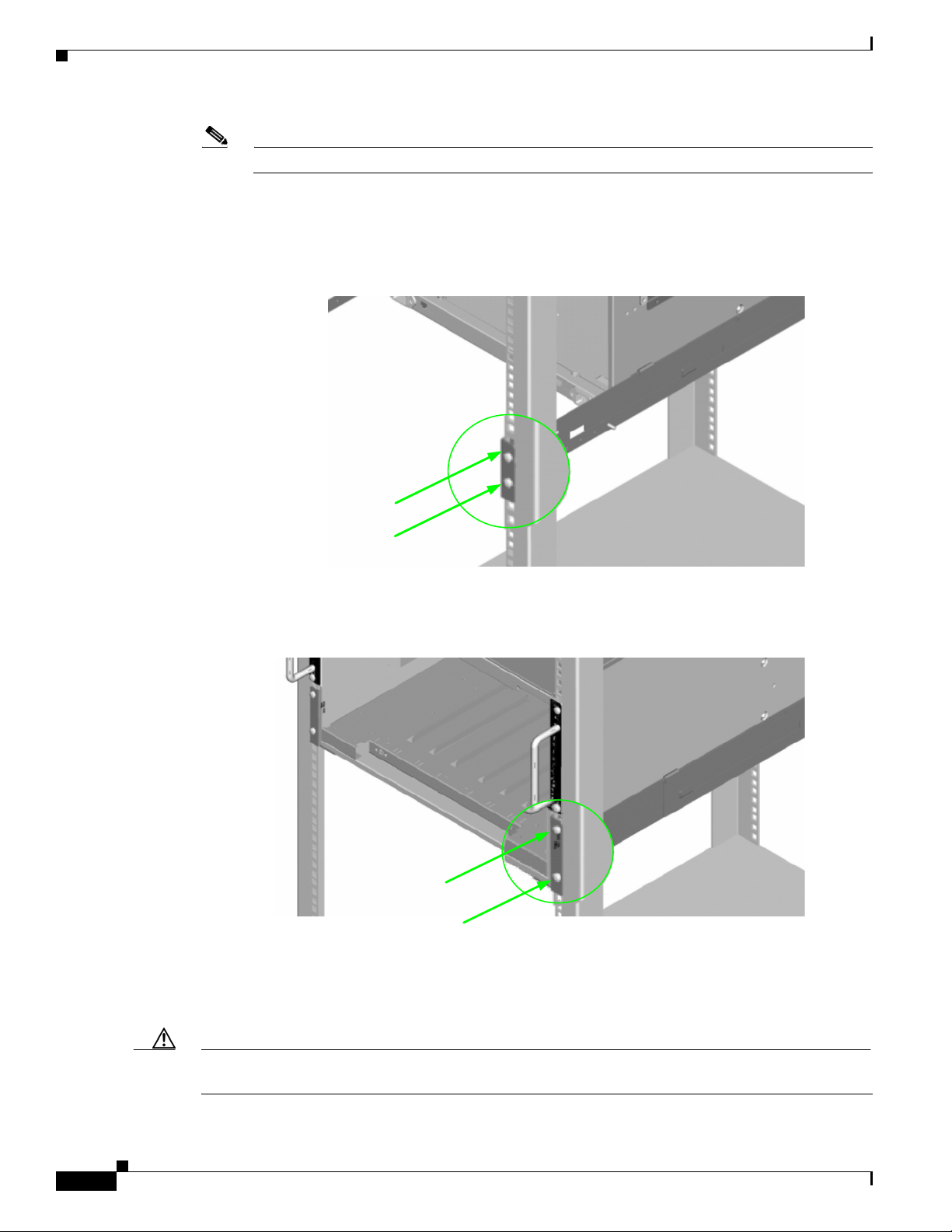
All holes should correspond to the rail mounting positions (i.e., the holes marked with pen or tape).
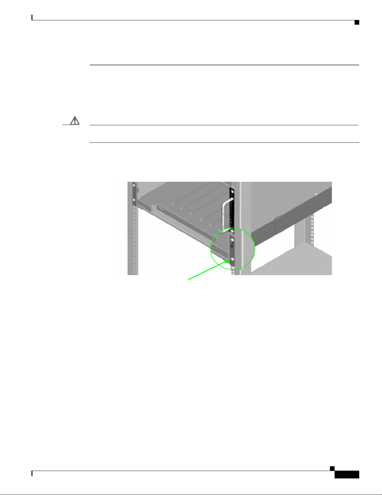
Step 2 Fasten the rail back flange (chassis leaf module side) to the rack by installing two screws into the rail
and rack.
Figure 1 Rail Back Flange
Install 2 screws to
top and bottom holes
Step 3 Fasten the rail front flange (chassis fan side) to the rack by installing one screw into the top hole of each
rail.
Figure 2 Rail Front Flange
Install the second rail on the other side of the rack by repeating steps 1 through 3.
Rack-Mount the Switch
Caution Because of its size and weight, it is recommended that either a lifting device or three (3) people install
the SFS 7012.
Install 2 screws to
top and bottom holes
1-14
Cisco SFS 7012 InfiniBand Server Switch Hardware Users Guide
OL-8787-05
Page 25
To install the switch into the rack, perform the following steps:
Step 1 Clear the area of any unnecessary materials.
Step 2 Attach the clip of the ESD wristband (strap) to bare metal on the cabinet. Put the wristband around one
wrist with the metal button against the skin.
Step 3 Lift the switch and from the front of the cabinet, slide it onto the rails. The fans and power supplies are
on the front of the chassis; leaf modules are to the rear.
Caution Never lift the switch with the handles on the spine modules, leaf modules, power supplies, and fan trays.
These handles are not designed to support the weight of the SFS 7012.
Step 4 Tighten the screw on the bottom of each side of the chassis into the corresponding bottom hole of the
front flange of each rail.
Figure 3 Secure Chassis to Rail
Install 1 screw into
bottom hole on each rail
Step 5 On each side of the chassis, install a screw and caged nut into the holes above and below the handle.
OL-8787-05
Cisco SFS 7012 InfiniBand Server Switch Hardware Users Guide
1-15
Page 26
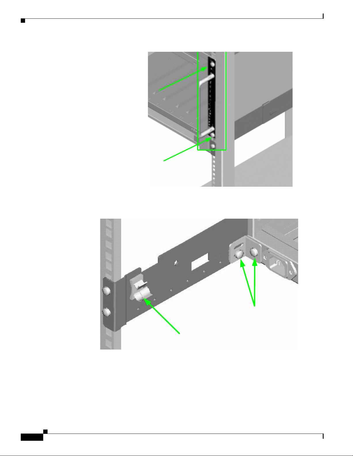
Figure 4 Secure Chassis to Rack
Install 1 screw and
caged nut into each
hole above and below
the handle
Step 6 Using two screws, install the lower mounting bracket to the rail assembly and chassis as shown in
Figure 5.
Figure 5 Install the Lower Mounting Bracket and Heyclip
Install the
heyclip here
Step 7 Install the heyclip to the rail assembly.
Step 8 If applicable, reinstall the chassis fascia(s).
Install the lower rear
mounting bracket to the rail
assembly and chassis
Installing the Switch Face Plate
To install the switch face plate(s):
Cisco SFS 7012 InfiniBand Server Switch Hardware Users Guide
1-16
OL-8787-05
Page 27

Step 1 On the switch fan side, insert the notches on the top of the fascia into the two slots on the chassis frame.
Snap the bottom of the faceplate in place.
Removing a Module or Blank
The handles are self-locking. To unlock, push up on the handles to disengage from the lock notch. Then
gently pull the handles out and slide the module out of the slot.
Note If removing, but not replacing a module, remember to replace with a module blank. All slots must be
either populated with a module or have blanks for EMI and thermal integrity.
Installing the Spine and Leaf Modules
Note The purchased configuration for the SFS 7012 is shipped fully populated. Follow these steps when it
becomes necessary to install or replace spine modules and leaf modules.
Step 1 Remove the necessary spine modules, spine module blanks, leaf modules, and leaf module blanks. For
detailed instructions, please refer to the section
Removing a Module or Blank, page 1-17.
Note If the user is only adding additional modules, remove only the blank(s) for the slot(s) to be populated.
These will not be replaced.
Step 1 When placing the spine modules and leaf modules into chassis slots, the following recommendations
apply:
a. Spine Modules — It is recommended that the spine module(s) be installed into:
–
Slot 1 for managed. For redundant management, populate slots 1 and 2 with management-capable
spines.
–
Slot 3 for unmanaged.
Refer to Figure 1-6 below:
OL-8787-05
Cisco SFS 7012 InfiniBand Server Switch Hardware Users Guide
1-17
Page 28
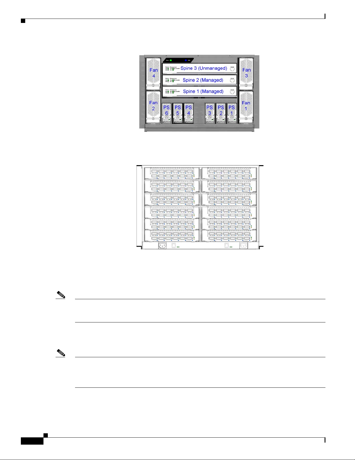
Figure 1-6 SFS 7012 Chassis — Spine Module Slot Numbering
b. Leaf Modules— Leaf modules should be populated beginning with slot 1, then slot 2, then slots 3
through 12 respectively. Refer to
Figure 1-7 SFS 7012 Chassis — Leaf Module Slot Numbering
Figure 1-7:
Leaf 11
Leaf 9
Leaf 7
Leaf 5
Leaf 3
Leaf 1 Leaf 2
Step 2 To install a module or filler, hold it so that the ejector handles are on the bottom.
Step 3 Pull the handles out to extend them. Slide the module into the appropriate slot of the chassis until it
makes contact with the backplane. As the module seats in the chassis, the handles will begin to close.
Step 4 Push the handles in to fully close.
Note Be sure that all cards are fully inserted in their respective chassis slots, and that the handles are in the
locked position. This prevents accidental removal, provides proper grounding for the system, and helps
to seat the bus connectors in the backplane receptacles.
Connect Equipment to the Ports and Power On the System
Leaf 12
Leaf 10
Leaf 8
Leaf 6
Leaf 4
1-18
Note Before performing the tasks in this section, take a few minutes to review Figure 1-8 and Figure 1-9
below. It is important to understand the slot numbering for the leaf modules and spine modules (and the
corresponding spine RJ-45 ports). It is also important to understand the slot numbering for the fans and
power supplies (and the corresponding AC power inlets for the power supplies).
Cisco SFS 7012 InfiniBand Server Switch Hardware Users Guide
OL-8787-05
Page 29
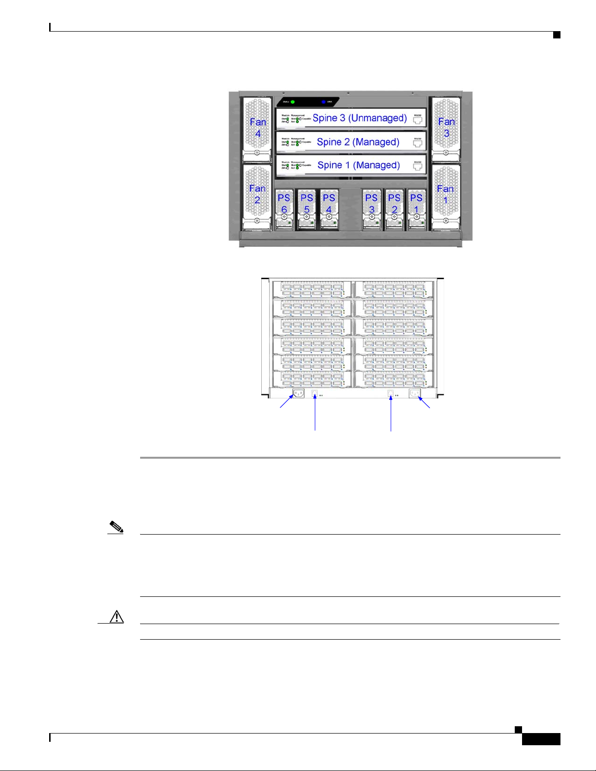
Figure 1-8 SFS 7012 Chassis Front View
Figure 1-9 SFS 7012 Chassis Back View
Leaf 11
Leaf 9
Leaf 7
Leaf 5
Leaf 3
Leaf 1
AC power inlet for power
supplies 1 to 3
RJ-45 for Spine 1 RJ-45 for Spine 2
Step 1 Connect a Category 5 or 6 (Cat 5/6) Ethernet cable to one of the RJ-45 connectors on the SFS 7012.
Connect the other end of the Cat 5/6 to the OOB LAN workstation. Refer to
Leaf 12
Leaf 10
Leaf 8
Leaf 6
Leaf 4
Leaf 2
AC power inlet for power
supplies 4 to 6
Figure 1-9 for which RJ-45
connector(s) to use:
Step 2 Connect the switch to IB-enabled hosts using 4X-to-4X IB cables.
Note Make sure all cables latch securely into the corresponding port connectors. If the IB cable connector is
not properly oriented to fit onto the port receptacle (i.e., while attempting to insert the cable in the port),
do not twist the connector to achieve the correct orientation. Instead, reach back a few feet on the cable,
and twist the bulk cable to allow the connector to rotate to the proper orientation. Doing this prevents all
of the rotational forces from acting right at the connector terminations.
OL-8787-05
Caution It is important to provide strain relief for the IB cable connector.
Cisco SFS 7012 InfiniBand Server Switch Hardware Users Guide
1-19
Page 30
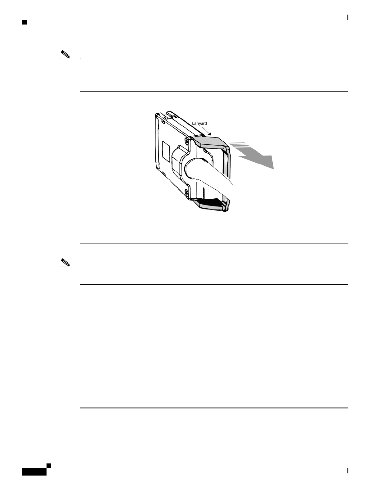
Note When handling IB connectors, make certain to remove the connectors by pulling on the center of the
Connecting Power
lanyard only as shown in
Figure 1-10 below. Pulling abruptly on the lanyard, or pulling on only one side
of the lanyard will prevent the latch/unlatch operation from occurring, and could damage or break the
lanyard.
Figure 1-10 4X IB Cable Connector
Step 1 Provide strain relief for the power cable(s) by feeding them into the heyclips on the lower rail assemblies.
Note Be certain that the power cords are firmly seated into the SFS 7012 AC power inlets. Depending upon
the purchased configuration, refer to Figure 1-9 to determine the correct AC power inlet to use.
Step 2 If necessary, replace the faceplates over the switch fans.
Step 3 Connect the power cables to an AC power outlet.
Step 4 When the SFS 7012 switch is plugged into an AC power outlet:
a. The system powers up.
b. The fans start.
c. The system performs a power-on self test (POST).
Step 5 The switch, power supply, and fan LEDs light up.
Bringing Up the System For the First Time
Start-up Procedures
Step 1 Power up the SFS 7012.
Step 2 From its flash image on the CMU spine module, the switch begins its boot process.
1-20
Cisco SFS 7012 InfiniBand Server Switch Hardware Users Guide
OL-8787-05
Page 31

Note If the spine module RS-232 port is connected to a terminal emulation program, the user will be able to
view the switch boot process. Be certain to use a null-modem/crossover serial cable for the console port.
The settings for the terminal emulation device should be:
–
8 data bits
–
no parity bits
–
1 stop bit
–
57600 baud
–
Use VT100 emulation.
–
Flow control = XON/XOFF
Figure 1-11 SFS 7012 RS-232 Connector
(Unmanaged)
Fan
3
2 (Managed)
1 (Managed)
Spine Module
RS-232 Port
Fan
PS3PS2PS
1
1
Step 3 The system prompts for a user name. In order to change the IP address and default gateway, the user must
be logged in as the administrator. At the prompt enter:
super
Step 4 The system prompts for a password. At the prompt enter:
super
The system responds with:
Welcome to the SFS 7012 CLI. Type 'list' for the list of commands.
Step 5 Verify the IP address with the command line interface (CLI) command showChassisIpAddr
command. The system returns the information similar to the following:
Chassis IP Address: 192.168.100.9 Net mask: 0xffffff00
Changing the IP Address and Default Gateway
There are 3 methods to change the IP address and default gateway of the chassis:
• Using the serial port.
• Logging into the CLI over Ethernet from a system that can reach the chassis using the default IP
address (192.168.100.9).
OL-8787-05
Cisco SFS 7012 InfiniBand Server Switch Hardware Users Guide
1-21
Page 32

• Use the Chassis Viewer GUI from a system that can reach the chassis using the default IP address
Using the RS232 Serial Port
Step 1 Connect null-modem/crossover serial cables to the RS-232 port of spine 1. If using a terminal emulation
device, the settings should be:
Step 2 Power up the switch.
Step 3 The system prompts for a user name. In order to change the IP address and default gateway, the user must
be logged in as the administrator. At the prompt enter:
Step 4 The system prompts for a password. At the prompt enter:
The system responds with:
Step 5 To change the SFS 7012 default IP address enter:
where -h ipaddress is the new IP address in dotted decimal (i.e., xxx.xxx.xxx.xxx) format, and -m
netMask is the new subnet mask in dotted decimal (i.e., xxx.xxx.xxx.xxx) format.
Step 6 To change the SFS 7012 default gateway IP address enter:
where -h ipaddress is the new default gateway IP address in dotted decimal (i.e., xxx.xxx.xxx.xxx)
format.
(192.168.100.9).
–
8 data bits
–
no parity bits
–
1 stop bit
–
57.6K baud
–
Use VT100 emulation.
–
Flow control = XON/XOFF
super
super
Welcome to the SFS 7012 CLI. Type 'list' for the list of commands.
setChassisIpAddr -h ipaddress -m netMask
setDefaultRoute -h ipaddress
Step 7 To to exit the CLI enter:
Using Telnet or SSH
Step 1 Power up the switch.
Step 2 Connect a Category 5 or 6 (Cat 5/6) Ethernet cable to the RJ-45 connector on spine 1. Connect the other
Step 3 Access the switch with the following command:
Step 4 The system prompts for a user name. In order to change the IP address and default gateway, the user must
Step 5 The system prompts for a password. At the prompt enter:
Cisco SFS 7012 InfiniBand Server Switch Hardware Users Guide
1-22
logout
end of the Cat 5/6 to an OOB LAN Ethernet hub or Ethernet switch where a work station can access the
7012. A work station can be connected directly to the Ethernet port of spine 1 of the 7012 if using a
crossover Ethernet cable. Power up the switch.
telnet 192.168.100.9
be logged in as the administrator. At the prompt enter:
super
OL-8787-05
Page 33

The system responds with:
Step 6 To change the SFS 7012 default IP address enter:
where -h ipaddress is the new IP address in dotted decimal (i.e., xxx.xxx.xxx.xxx) format, and -m
netMask is the new subnet mask in dotted decimal (i.e., xxx.xxx.xxx.xxx) format.
Note After changing the IP address the chassis TELNET/SSH session is terminated and must be
Step 7 To change the SFS 7012 default gateway IP address enter:
where -h ipaddress is the new default gateway IP address in dotted decimal (i.e., xxx.xxx.xxx.xxx)
format.
Step 8 To to exit the CLI enter:
Using the Chassis Viewer GUI
Step 1 Power up the switch.
Step 2 Connect a Category 5 or 6 (Cat 5/6) Ethernet cable to the RJ-45 connector on spine 1. Connect the other
end of the Cat 5/6 to an OOB LAN Ethernet hub or Ethernet switch where a work station can access the
7012. A work station can be connected directly to the Ethernet port of spine 1 of the 7012 if using a
crossover Ethernet cable. Power up the switch.
super
Welcome to the SFS 7012 CLI. Type 'list' for the list of commands.
setChassisIpAddr -h ipaddress -m netMask
reopened using the new IP address.
setDefaultRoute -h ipaddress
logout
Step 3 To start Chassis Viewer, open a web browser and enter the default IP of the switch (i.e., 192.168.100.9).
Note The browser must be on a workstation connected to the same Ethernet LAN, and on the same
TCP/IP subnet as the switch RJ-45 OOB LAN port.
Note Chassis Viewer supports the following browsers: Microsoft Internet Explorer 6.0+ and Mozilla
version 1.6.x+
Note If the user is leaving their workstation for a period of time, be sure to close the browser window.
Step 4 If web authentication is enabled, the following screen will be displayed:
Note If web authentication is not enabled, skip to Step 5.
OL-8787-05
Cisco SFS 7012 InfiniBand Server Switch Hardware Users Guide
1-23
Page 34

Figure 12 SFS 7012 Web Authentication
Enter the user name super and password super.
Step 5 From the chassis OOB LAN IP submenu, click Set OOB LAN IP. The Set OOB LAN IP is displayed:
Step 6 Click in the OOB IP Address field.
Figure 13 Set OOB LAN IP Window
Step 7 Enter the new switch IP address.
Step 8 Click in the Net Mask field.
Step 9 Enter the new net mask.
Step 10 Click Apply. The following screen is displayed:
Figure 14 OOB LAN IP Confirmation Window
When the user clicks OK the Chassis Viewer refreshes and uses the new IP address.
Step 11 To change the switch default gateway, from the main menu select OOB LAN IP then Set Default
Gateway IP. The following screen is displayed:
Figure 15 Set Default Gateway IP Window
1-24
Step 12 Click in the Gateway address field.
Cisco SFS 7012 InfiniBand Server Switch Hardware Users Guide
OL-8787-05
Page 35

Step 13 Enter the new switch default gateway IP address.
Step 14 Click Apply.
Note A reboot is required to activate the new gateway IP address.
Updating Management Spine IP Addresses in a Redundant Management Configuration
Note This procedure should be performed the first time the SFS 7012 is powered on.
Each managed spine must have a unique IP address that is different than the chassis IP address of the
SFS 7012. Therefore, a redundantly-managed SFS 7012 will have three (3) unique IP addresses. The
current default IP addresses are:
–
Chassis: 192.168.100.9
–
Spine 1: 192.168.100.11
–
Spine 2: 192.168.100.12
It is necessary for each managed spine to have a unique IP address for the following reasons:
• Unique IP addresses are used when sending syslog messages from a managed spine to a syslog
server.
• Gives the user the ability to ping each management spine separately.
• If the IP addresses are not unique, collisions will occur, causing IP operations to fail.
To update the IP address on a managed spine, do the following:
Step 1 Ensure that the spine module is connected to a COM port on a serial terminal device via the RS-232 port.
Step 2 Get to a [boot]: prompt by following Step a or b.
a. If the managed spine is running, enter the following command at the console:
reboot
Then press Enter.
b. If the managed spine is not running, power on the switch.
Step 3 After selecting image1 or image2, press the Spacebar to interrupt the auto load sequence before the
counter expires (within 5 seconds).
Step 4 At the [boot]: prompt enter the new spine IP address with the following syntax:
spineip <NEW IP ADDRESS>
Then press Enter.
OL-8787-05
Cisco SFS 7012 InfiniBand Server Switch Hardware Users Guide
1-25
Page 36

Step 5 At the [boot]: prompt, enter reboot, and press Enter. Upon reboot the managed spine will display
information similar to the following:
Unified Boot Manager For The T3 Platform.
Image Date: Jan 19 2006, 15:03:31
Checking L2 functionality...
BCM1125
L2 caches initialized and invalidated
CPU0 caches initialized
Initialized SMBUS Channels
SPD Checksum ok.
MEM_SEL = 0x00000007
CPU_REV = 0x00000001_112421FF
CPU speed = 400 MHz
IO Bridge 0,1 speed = 133, 200 MHz
Memory size = 128 MB
MC1 Configured for 128M SODIMM, CAS=2, 100 MHz
Configured Memory Size = 0x08000000
Channel Interleave Bit = 0
Number of Mem Channels = 1
Testing memory
Memory tests pass
CPU0 flushing caches
L2 flush complete
Start type = 0xBFC006A0
Jumping to romStart
Initializing HyperTransport bus
HyperTransport initialization completed
rintf MBOX connect interrupt_source=28 vector=62 status=0
Printf MBOX intEnable status=0
Found Intel Strata Flash 128 MBit (0x8918).
Mounted raw file system on device /image1. (size=6291456 bytes)
Mounted raw file system on device /image2. (size=6291456 bytes)
Mounted raw file system on device /dump0. (size=1048576 bytes)
Mounted flash file system on device /rfa1. (size=2097152 bytes)
Unified Boot Manager
[1] image1
[2] image2
CPU: Broadcom BCM1125
VxWorks Version: 5.4
[boot]:
Unified Boot Manager For The T3 Platform.
Image Date: Jan 19 2006, 15:03:31
Checking L2 functionality...
BCM1125
L2 caches initialized and invalidated
CPU0 caches initialized
Initialized SMBUS Channels
SPD Checksum ok.
MEM_SEL = 0x00000007
CPU_REV = 0x00000001_112421FF
CPU speed = 400 MHz
IO Bridge 0,1 speed = 133, 200 MHz
Memory size = 128 MB
MC1 Configured for 128M SODIMM, CAS=2, 100 MHz
Configured Memory Size = 0x08000000
Channel Interleave Bit = 0
Number of Mem Channels = 1
Testing memory
Memory tests pass
1-26
Cisco SFS 7012 InfiniBand Server Switch Hardware Users Guide
OL-8787-05
Page 37

CPU0 flushing caches
L2 flush complete
Start type = 0xBFC006A0
Jumping to romStart
Initializing HyperTransport bus
HyperTransport initialization completed
rintf MBOX connect interrupt_source=28 vector=62 status=0
Printf MBOX intEnable status=0
Found Intel Strata Flash 128 MBit (0x8918).
Mounted raw file system on device /image1. (size=6291456 bytes)
Mounted raw file system on device /image2. (size=6291456 bytes)
Mounted raw file system on device /dump0. (size=1048576 bytes)
Mounted flash file system on device /rfa1. (size=2097152 bytes)
Unified Boot Manager
[1] image1
[2] image2
CPU: Broadcom BCM1125
VxWorks Version: 5.4
boot device : icspkg0
processor number : 0
host name : home
file name : /image1
inet on ethernet (e) : <NEW IP ADDRESS>
inet on backplane (b):
host inet (h) : 192.168.100.1
gateway inet (g) :
user (u) : ftp
ftp password (pw) (blank = use rsh): ftp
flags (f) : 0x0
target name (tn) :
startup script (s) :
other (o) : sbe
Loading package from flash device /image1 ...
Boot System = 7012
Boot Image Information:
Product = SFS7012
BSP = t3
Version = 4.1.1.1.11
Compressed Image Size = 3616523 bytes
md5 = 46086777be1b5bae45140a440425b915
vxWorks Image Type = loadable
Computed md5 = 46086777be1b5bae45140a440425b915
md5 values match!
11088736
Starting at 0x80010000...
sysI
REGS
BOOT
Initializing HyperTransport bus
HyperTransport initialization completed
Found Intel Strata Flash 128 MBit (0x8918).
Mounted raw file system on device /image1. (size=6291456 bytes)
Mounted raw file system on device /image2. (size=6291456 bytes)
Mounted raw file system on device /dump0. (size=1048576 bytes)
Mounted flash file system on device /rfa1. (size=2097152 bytes)
Network configuration requested.
cliEnabled=1
sbe0 speed=100 fullDuplex=0 flowControl=0
OL-8787-05
Cisco SFS 7012 InfiniBand Server Switch Hardware Users Guide
1-27
Page 38

sbe1 speed=100 fullDuplex=1 flowControl=0
Note The command spineip changes the IP address for image1 and image2,
SFS 7012 Component LEDs
Chassis Status LED
The chassis status LED is Green when the system is functioning normally.
The chassis status LED is Amber when one of the following conditions exists:
• The system ambient temperature exceeds 52 C but remains less than 60 C.
• Any Fan Alarm is amber.
• Any power supply AC OK LED is off.
• Any power supply DC OK LED is off
• Any spine module Attention LED is on, or it has been determined that a spine is not functioning
(even if it is unable to light the LED).
• Any leaf module Attention LED is on, or it has been determined that a leaf is not functioning (even
if it is unable to light the LED).
The chassis status LED is Red when the system can no longer function properly and indicates one of the
following conditions:
• The system ambient temperature exceeded 60 degrees C.
• No functional fan trays are present.
• No functional spines are present.
• No functional leaves are present.
The chassis status LED is off when:
• There are no functional power supplies present.
• There are no management cards in the system
• AC power has been removed from the system.
Subnet Manager Agent (SMA) LED
There is a single SMA LED associated with the system. This LED is Blue if any external InfiniBand
links have been established. If no external IB links have been established, the LED if off.
RJ45 LEDs
The SFS 7012 RJ45 connector has two LEDs, Act and 100. The 100 LED is Green when a 100Mbps
link is connected. The Act LED is Green when an Ethernet link has been established, and blinking when
the link is active.
Fan LEDs
Fan LEDs indicate the following status(es):
1-28
• Green indicates that the fan is functioning properly.
Cisco SFS 7012 InfiniBand Server Switch Hardware Users Guide
OL-8787-05
Page 39

• Amber indicates that the following warning condition exists:
–
A single fan rotation failure at less than 4000 RPM or greater than 10950 RPM.
• Red indicates a possible problem, including:
–
The fan tray is not responding to commands for configuration and temperature-related
operations.
–
A fan is not responding to commands for temperature and speed related operations.
–
The fan speed has fallen below the minimum allowed RPM for a fan.
Power Supply LEDs
Each SFS 7012 power supply has two LEDs: DC OK and AC OK. Following are the statuses for each.
DC OK
–
Green indicates that DC power is normal.
–
Off indicates a DC power failure or no DC power is present.
AC O K
–
Green indicates that AC power is normal.
–
Off indicates a AC power failure or no AC power is present.
SFS 7012 Leaf and Spine Module LEDs
Leaf Module IB Port LEDs
Each SFS 7024 leaf module port has a Blue IB link status LED that provide the following indications:
• On - the logical link is up (port is in the Active state).
• Off - the physical link is down (port is in the Down state).
Spine and Leaf Module Status LED
The status LED indicates one of the following conditions:
• Steady Green - the module is operating normally.
• Blinking Green - LED test state.
• Off - module is in the removable state.
Spine and Leaf Module Attention LED
The Attention LED indicates one of the following conditions:
• Off - the system functioning normally.
• Steady Amber - the system requires some attention, which could indicate one of the following
conditions:
–
The switch temperature is at a warning level on the module.
–
The switch silicon temperature is at a warning level (approximately 90 degrees C).
OL-8787-05
–
DC voltages on the board are slightly out of tolerance (12V Bulk, 5V, 3.3V, 1.8V, VBIO are all
monitored).
Cisco SFS 7012 InfiniBand Server Switch Hardware Users Guide
1-29
Page 40

–
The module can no longer function properly. The system will take the appropriate actions to
ensure that no damage is done to its components.
• Blinking Amber (once every four seconds) - LED test state.
Spine Module Management LEDs
Each SFS 7012 spine module has three management LEDs:
• Capable:
–
Green indicates that the spine slot supports management.
–
Off indicates that the spine slot does not support management.
• Stat:
–
Green indicates that a management board is present.
–
Off indicates that no management board is present.
• Act:
–
Green indicates that management board is in the active mode. In a redundantly-managed
system, this would indicate the master spine.
–
Off indicates that the management board is in the standby mode (if the STAT LED is Green).
In a redundantly-managed system, if the Capable LED is also Green, this would indicate the
slave spine.
• DDR:
–
Green indicates that the switch is capable of running at DDR speeds.
–
Off indicates that the switch is not capable of running at DDR speeds (i.e., SDR only).
Shutdown Procedures
In order to shutdown the SFS 7012:
Step 1 Power down the switch by removing the power cords from the AC power inlets.
Hot Swapping Components
Hot Swapping Spine and Leaf Modules
Note Following are the general guidelines for hot swapping leaf and spine modules:
Caution Be certain that the managed spine to be hot swapped is a that same firmware level as all other
components in the SFS 7012. A hot swap of a managed spine with another firmware level will cause a
disruptive reboot (i.e., I/O traffic is interrupted).
1-30
Cisco SFS 7012 InfiniBand Server Switch Hardware Users Guide
OL-8787-05
Page 41

• Hot swap one module at a time, allowing the chassis to completely update it before hot-swapping
the next module. The module update is complete when it becomes visible within the Chassis Viewer
GUI. Listed below are the approximate times to fully update each module type:
–
Spines modules: up to 4 minutes
–
Leaf modules: up to 2 minutes
• When a management spine is hot swapped, the rest of the chassis will continue to move packets
without interruption.
• There is no need to reboot the chassis when replacing either a spine or leaf module.
Step 1 Remove the module by pushing up on the handles to disengage from the lock notch. Once the handles
are disengaged, gently pull the handles out and slide the module out of the slot.
Step 2 To install a module, hold it so that the ejector handles are on the bottom.
Step 3 Pull the handles out to extend them. Slide the module into the appropriate slot of the chassis until it
makes contact with the backplane. As the module seats in the chassis, the handles will begin to close.
Step 4 Push the handles in to fully close.
Hot Swapping the Fan Unit
Step 1 Loosen the captive panel screw.
Step 2 Pull the panel screw down to partially disengage the unit.
Step 3 Slowly pull the unit. The unit will disengage from the connector.
Step 4 Carefully slide the fan out until it is completely removed from its slot.
To install a fan unit:
Step 1 Place the unit into the slot. Slowly slide the fan unit in until it engages into the connector.
Step 2 Using the panel screw, push up to re-engage the unit.
Step 3 Tighten the captive panel screw.
Hot Swapping Power Supplies
The SFS 7012 switch requires a minimum of three power supplies for normal operation. Power supplies
can be hot swapped without powering down the switch. To replace a power supply:
Step 1 Loosen the captive panel screw.
Step 2 Pull the panel screw down to partially disengage the unit.
Step 3 Slowly pull the unit. The unit will disengage from the connector.
Step 4 Carefully slide the power supply out until it is completely removed from its slot.
Step 5 To install a power supply:
Step 6 Place the unit into the slot. Slowly slide the power supply in until it engages into the connector.
OL-8787-05
Step 7 Using the panel screw, push up to re-engage the unit.
Cisco SFS 7012 InfiniBand Server Switch Hardware Users Guide
1-31
Page 42

Step 8 Tighten the captive panel screw.
1-32
Cisco SFS 7012 InfiniBand Server Switch Hardware Users Guide
OL-8787-05
Page 43

CHAPTER
2
Operations and Administration
This chapter describes how to administer and configure the Cisco SFS 7012™ and its components, and
it includes the following information:
• Logging, page 2-12
• Maintenance, page 2-17
• SNMP, page 2-20
• Configuration File Administration, page 2-25
• Chassis Traps, page 2-29
• SFS 7012 Port Statistics, page 2-32
• Time Service, page 2-38
• Configuring the Switch OOB IP Address, page 2-41
Chassis Viewer
The Chassis Viewer is Cisco's browser-based management software. The Chassis Viewer provides the
primary management interface for the SFS 7012 switch, allowing the user to perform management,
configuration, and monitoring tasks related to InfiniBand networks.
• The Chassis Viewer runs on the Chassis Management Unit (CMU) of the SFS 7012 managed spine
modules.
• The browser must be on a workstation which has connectivity to the RJ-45 OOB LAN port on the
switch.
• Management Workstation Requirements
–
• To access the Chassis Viewer, point a browser to the IP address of the SFS 7012.
• If user authentication is enabled, the following screen is displayed:
Browser Level: Internet Explorer 6.0 (Windows) or Mozilla Firefox 1.5.0.4+ (Linux)
OL-8787-05
Cisco SFS 7012 InfiniBand Server Switch Hardware Users Guide
2-1
Page 44
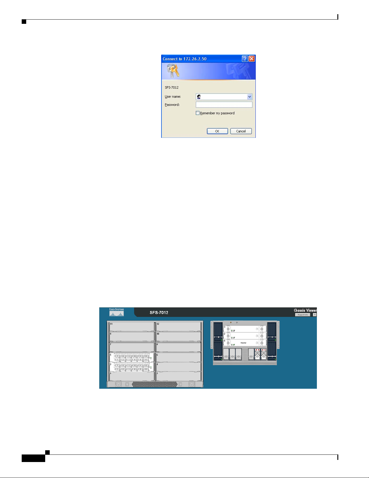
Figure 1 SFS 7012 Web Authentication
• Enter the default user name and password:
–
Administrator-level user name: super
–
Administrator-level password: super
–
Operator-level user name: admin
–
Operator-level password: admin
• The Chassis Viewer home page is displayed.
The Chassis Viewer Manages
Home Page
• The SFS 7012 chassis.
• Each SFS 7012 leaf module.
• Each SFS 7012 spine module.
• Logging and monitoring functionality.
Figure 2-2 Chassis Viewer Home Page
The Chassis Viewer home page provides a high-level overview of the SFS 7012 switch and individual
leaf and spine modules. This area is the starting point to more detailed information for the SFS 7012
chassis and components (fans and power supplies), leaf modules and spine modules. The selected
component provides hyperlinks to related menus and information where the user can perform
configuration and monitoring tasks.
2-2
Cisco SFS 7012 InfiniBand Server Switch Hardware Users Guide
OL-8787-05
Page 45

? (Help) Button
Support Button
Figure 2-3 Help Button
The ? (HELP) button displays online help. Each help screen gives the user a high-level, topic-specific
description.
Figure 2-4 Support Button
The Support button displays key contact information for support, displayed in the following window:
Figure 2-5 Support Contact Screen
Displaying the Leaf and Spine Module Views
Leaf Module View
To display the leaf module view for the SFS 7012:
Step 1 Mouse over the leaf module to display. The edges of the leaf module are highlighted green as shown in
Figure 2-6 below:
Cisco SFS 7012 InfiniBand Server Switch Hardware Users Guide
OL-8787-05
2-3
Page 46

Figure 2-6 Leaf Module Mouseover
Left click the mouse. The leaf module view will be displayed.
Figure 2-7 Leaf Module View
Spine Module View
To display the spine module view for the SFS 7012:
Step 1 Mouse over the spine module to display. The edges of the spine module are highlighted green as shown
in
Figure 2-8 Spine Module Mouseover
Left click the mouse. The spine module view will be displayed.
Figure 2-8 below:
2-4
Cisco SFS 7012 InfiniBand Server Switch Hardware Users Guide
OL-8787-05
Page 47

Figure 2-9 Spine Module View
Leaf and Spine Module Component Details Area
The Component Details Area contains three areas.
• Details Header
• Information area.
• Menu
Figure 2-10 Leaf and Spine Component Details Area
Leaf and Spine Details Header
The leaf and spine Details Header allows the user to execute the most common tasks for the SFS 7012
switch:
• Display the Home page
• View field-replaceable unit (FRU) information.
• Access online help
Figure 2-11 Leaf and Spine Details Header
Leaf and Spine Information Area
The Leaf and Spine Information Area allows the user to view high-level information for each specific
leaf or spine module. The information area contains two different fields:
• The white fields allow the user to add or modify applicable general and system information that is
specific to their environment.
OL-8787-05
Cisco SFS 7012 InfiniBand Server Switch Hardware Users Guide
2-5
Page 48

• The gray fields are tied to live data from the selected hardware component as well as live system
information.
Additionally, the Component Information Area has Apply and Refresh buttons, which perform the
following functionality:
Apply:
Saves any user edits within the white fields to flash memory.
Refresh:
Refreshes all fields in the information areas.
Displaying the Chassis View
There are two ways to display the chassis view for the SFS 7012:
Step 1 Mouse over the outer region of the leaf module view. The edges of the chassis are highlighted green as
shown in
Figure 2-12 Leaf Module Chassis Mouseover
Figure 2-12 below:
2-6
Left click the mouse. The chassis view will be displayed.
Step 2 The second way is to mouse over the outer region of the spine module view. The edges of the chassis are
highlighted green as shown in
Figure 2-13 Spine Module Chassis Mouseover
Figure 2-13 below:
Left click the mouse. The chassis view will be displayed.
Cisco SFS 7012 InfiniBand Server Switch Hardware Users Guide
OL-8787-05
Page 49

Figure 2-14 Chassis Viewer Component Details Area
Chassis View Component Details Area
The Component Details Area contains three areas.
• Details Header
• Information area.
• Menu
Chassis Details Header
The Chassis Details Header allows the user to execute the most common tasks for the SFS 7012 switch:
• Display the Home page
• View Log
Figure 2-15 Chassis Details Header
Rebooting Components from Chassis Viewer
Step 1 From the Chassis Details header, click Reboot. A screen similar to the following is displayed.
OL-8787-05
Cisco SFS 7012 InfiniBand Server Switch Hardware Users Guide
2-7
Page 50

Figure 2-16 Reboot Screen
Step 2 Select the radio button of the spine(s) to be rebooted, or select the Reboot Entire Chassis radio button
to reboot the SFS 7012 chassis and all spines.
Step 3 Click Reboot.
Chassis View Component Information Area
Figure 2-17 Component Information Area
The Chassis View Component Information Area allows the user to monitor important information for
each specific hardware component, as well as important system information. The information area is
comprised of two different fields:
• The white fields allow the user to add or modify applicable general and system information which
is specific to their environment.
• The gray fields are tied to live data from the selected hardware component as well as live system
information.
Additionally, the Component Information Area has Apply and Refresh buttons, which perform the
following functionality:
Apply:
Saves any user edits within the white fields to flash memory.
Refresh:
Refreshes all fields in the information areas.
Chassis View Component Information Area Tabs
The tabs along the top of the information area present information about the following components:
• LED and sensor information
• Overall system information
• Switch Field Replaceable Unit (FRU) Information
2-8
• Power supply information
Cisco SFS 7012 InfiniBand Server Switch Hardware Users Guide
OL-8787-05
Page 51

LEDs and Sensors Tab
• Fan information
• Switch backplane information
The LEDs and Sensors tab displays:
• Switch component LED information for chassis status, chassis SMA, fan and power supplies.
• Slot-based temperature and AC-power sensor data for the internal switching complex.
Figure 2-18 LEDs and Sensors Tab
System Tab
Note For a detailed explanation of physical LEDs on the hardware components, please refer to the section SFS
7012 Component LEDs, page 1-28.
The System tab displays the overall system information of the SFS 7012. This information includes the
following items:
Out of Band LAN IP
The IP address of the switch.
Netmask
The current net mask settings for the chassis.
System Description
A read-only textual description of the system.
IB Node Description
Assigned by the administrator, the IB node description is an IB fabric-applicable name that will be
displayed within a subnet manager GUI. Note that changes to this field will be visible to the outside
systems only after the chassis is rebooted. To reset this field to the default setting, click the Field
Default button.
Note If the IB Node Description field has been changed since the last reboot of either spine, the next
reboot will be treated as disruptive.
OL-8787-05
Cisco SFS 7012 InfiniBand Server Switch Hardware Users Guide
2-9
Page 52

Chassis FRU Tab
System Uptime
The elapsed time since the last time switch was re-initialized.
System Contact
The textual identification of the contact person and their contact information for this system,
assigned by the administrator.
System Name
The name for the system, assigned by an administrator. One convention is to use the system's fully
qualified domain name as the System Name.
System Location
The location of the system, assigned by an administrator.
Apply Button
Saves any changes made by the user in the System tab to memory.
Refresh Button
Refreshes all fields in the System tab.
The Chassis FRU tab displays switch Field Replaceable Unit (FRU) information. This information
includes the following items:
Type
Power Tab
The type of component.
Description
A description of the component, assigned by an administrator.
Alias Name
Name of the component, assigned by an administrator.
Serial Num
Component serial number
Detail
A button for each row that displays additional detail about the component. Additional details
include: Part Number, Model, Version, Manufacturer Name, Product Name, Manufacturer
Identification, and Manufactured Date.
Apply Button
Saves any changes made by the user in the Chassis FRU tab to memory.
Refresh Button
Refreshes all fields in the Chassis FRU tab.
The Power tab displays switch power supply information. This information includes the following items:
2-10
Description
A description of the component, assigned by an administrator.
Cisco SFS 7012 InfiniBand Server Switch Hardware Users Guide
OL-8787-05
Page 53

Fan Tab
Backplane Tab
Status
Displays the status of the component.
Part Num
Displays the part number of the component.
Detail
A button for each row that displays additional detail about the component. Additional details
include: Model, Version, Manufacturer Name, Product Name, Manufacturer Id, Manufactured Date
Apply Button
Saves any changes made by the user in the Power tab to memory.
Refresh Button
Refreshes all fields in the Power tab.
The Fan tab displays switch fan information. For descriptions of the fields, see the Power Tab.
The Backplane tab displays switch backplane information. For descriptions of the fields, see the Power
Tab.
Additionally, the user can modify the Description field, adding information specific to their network
environment.
Modifying Switch Component Information
Following is the procedure for modifying the fields for switch components:
Step 1 Select the applicable tab; System, Chassis FRU, Power, Fan, or Backplane.
Step 2 Click on the row to be modified.
Step 3 In the text boxes, enter information which is applicable to the existing network environment.
Step 4 To save, click the Apply button at the bottom of the screen.
Figure 2-19 System Information Area
OL-8787-05
Cisco SFS 7012 InfiniBand Server Switch Hardware Users Guide
2-11
Page 54

Configuration and Monitoring Features
The following section provides detailed, task-oriented descriptions for configuring and monitoring the
SFS 7012 switch and its feature functionality.
Chassis View Menu
Figure 2-20 Chassis View Menu
The Chassis View Menu allows the user to execute all configuration and operation tasks available for
the SFS 7012 switch.
Logging
Set Level
The Logging submenu allows the user to set and reset levels for the message log file.
Figure 2-21 Logging Submenu
Figure 2-22 Set Level Button
The Set Level button allows the user to set log level configuration parameters for all software modules
on the SFS 7012.
2-12
To set log levels:
Cisco SFS 7012 InfiniBand Server Switch Hardware Users Guide
OL-8787-05
Page 55

Step 1 From the menu, select Logging.
Step 2 From Logging, select Set Level. The Log System Configurator (Device Tab) window is displayed:
Figure 2-23 Log System Configurator (Device Tab)
The Device tab presents current log level configuration settings for the following software modules:
–
RAM = The circular log buffer contained in memory. To access the contents of this buffer, use
the Chassis Viewer View Log button
–
Syslog = Messages that are sent to a syslog host specified on the Syslog tab.
From this screen, the user can change any of the log level settings for a specific software module by
clicking on the Configure hyperlink, which displays a configuration screen:
Figure 2-24 Device Tab: Software Module Configurator
OL-8787-05
To change any Log Level settings:
Step 1 Click the On-Off checkbox to the right of the setting.
Step 2 Click the Submit button to save any changes.
The following list describes each of the Log Level configuration parameters.
–
DUMP – Dump: Indicates that a problem has caused the system to produce a system dump file.
In most circumstances, it is recommended that the user retrieve the dump that was produced.
Support engineers may require the information contained in the dump file to diagnose the cause
of the problem.
Cisco SFS 7012 InfiniBand Server Switch Hardware Users Guide
2-13
Page 56

–
FATAL – Indicates that a non-recoverable system problem has occurred. The user should reboot
the system or component and verify that the subsystem is fully functional to determine whether
the fault has been corrected. If the problem persists, the user should contact the supplier.
–
ERROR – Indicates that a serious system error has occurred which might be recoverable. If the
system exhibits any instability, the user should reboot the system or component. If errors persist,
the user should immediately contact the supplier's technical support.
–
ALARM - Indicates that a serious problem has occurred which degrades capacity or service. If
the error is recoverable, the user should correct the failure. If the alarm/failure persists, the user
should reboot the system at a convenient time. If the problem is still not cleared, the user should
contact the supplier.
–
WA RN I NG - Indicates that a recoverable problem has occurred. The user does not need to take
action.
–
PART IAL - When more information is available, Partial causes additional message-related
details to be displayed.
–
CONFIGURATION: An informational message indicating changes that a user has made to the
system configuration. The user does not need to take any action.
–
INFO: Informational messages that occur during a system or component boot. The user does
not need to take any action.
–
PERIODIC: An informational message containing periodic statistics. The user does not need
to take action.
Debug message levels 1 through 5: Debug messages are for supplier and/or Cisco engineering use
and are not necessarily indicative of actions that an end user may need to take.
Preset Tab
–
DEBUG1 – Messages that describe the states of connections and links.
–
DEBUG2 – Messages that describe major configuration changes or operations.
–
DEBUG3 – Messages that describe the I/O flow.
–
DEBUG4 – Messages that contain the packet dumps within an I/O flow. I/O flows contain
multiple packets.
–
DEBUG5 – Messages that contain the packet dumps within an I/O flow. I/O flows contain
multiple packets.
Note When configuring the log levels to display debug messages, care should be taken to ensure that system
performance issues are weighed against troubleshooting requirements. Generally, the higher the debug
number the more information is written to the log. Specifically, debug 3-5 have the most effect on system
performance.
The Preset tab allows the user to quickly change log level settings for all software modules on the switch.
2-14
Cisco SFS 7012 InfiniBand Server Switch Hardware Users Guide
OL-8787-05
Page 57

Syslog Tab
Figure 2-25 Log System Configurator: Preset Tab
To change the log level settings:
Step 1 Click the On-Off checkbox to the right of the setting(s).
Step 2 Click the Submit button to save any changes.
Figure 2-26 Log System Configurator: Syslog Host Tab
The Syslog tab allows the user to configure logging messages to be sent to a syslog host. If the Host IP
address is 0.0.0.0, no syslog host is configured, otherwise log messages are sent to the syslog server at
a specified IP address and port.
To setup the syslog host:
Step 1 In the Host IP dialog box, enter the IP address of the syslog host where the log files are to be saved.
Step 2 Click the Apply button to save the IP address.
Configure Syslog on a Linux Server
Step 1 Edit the /etc/sysconfig/syslog file and ensure that the -r is included in the
SYSLOGD_OPTIONS. This allows logging from a remote system. For example:
SYSLOGD_OPTIONS="-r -m 0"
Step 2 Type /etc/init.d/syslog restart, and press Enter.
OL-8787-05
Cisco SFS 7012 InfiniBand Server Switch Hardware Users Guide
2-15
Page 58

Note To centralize logging for all switches in an IB fabric, the user can configure each switch to point to the
Reset Log Levels
Step 1 From the menu, select Logging.
Step 2 Click Logging.
Step 3 Click Reset Levels. The Reset Levels window is displayed:
same syslog server that has the syslog daemon (syslogd) running. When messages are sent to a syslog
server, they will appear in the log as being sent from the IP address of the master spine.
The Reset Levels button resets the logging levels to their factory default values.
Figure 2-27 Reset Levels Button
To reset the logging levels:
Figure 2-28 Reset Log Levels Window
Step 4 To reset the logging levels, click OK.
2-16
Cisco SFS 7012 InfiniBand Server Switch Hardware Users Guide
OL-8787-05
Page 59

Maintenance
Note For rebooting information, see Rebooting Components from Chassis Viewer, page 2-7
Firmware Update
Figure 2-29 Maintenance Menu
Figure 2-30 Firmware Update Button
The Firmware Update button allows the user to select an alternate firmware file for the SFS 7012. These
alternate files are reflected in the drop-down lists in the Firmware Update screen.
To dow nl o a d fi r m w a r e :
Step 1 From the menu, select Maintenance.
Step 2 Click Firmware Update. The Firmware Update screen is displayed.
Figure 2-31 Firmware Update Screen
OL-8787-05
Step 3 In the Select Target Slot Column, select the hardware component to change its firmware.
Cisco SFS 7012 InfiniBand Server Switch Hardware Users Guide
2-17
Page 60

Note If there are multiple spine modules, the user can select all applicable slots.
Step 4 From the Image to Overwrite drop-down list, choose a firmware image to overwrite.
Step 5 In the Firmware Update Package: text box, enter the path to the alternate firmware file. If the path is
not known, the user can use the Browse... button to locate it.
Step 6 To have the new image become active after the next reboot, check the box in the Boot? Column.
Step 7 Click the Update Firmware button.
Note Before using the Browse... button, make certain that the browser can connect to the server where the
firmware files reside.
LDAP Configuration
Figure 2-32 LDAP Configuration Button
The lightweight directory access protocol (LDAP) configuration feature allows the user to set and
configure authentications for the switch. The LDAP service resides on a server that has access to a user
code and password database.
On a SFS 7012 with LDAP enabled, when a user attempts to login to either Chassis Viewer or the CLI,
the LDAP client intercepts the login attempt and rather than authenticating internally, encrypts and
packages the information in an LDAP packet and sends it to a pre-configured LDAP server over TCP/IP
(i.e., the out of band LAN). The LDAP server receives the request, passes it on to the authentication
services, and responds to the client with a yes or no, either allowing or denying the user access to the box.
When LDAP is disabled internal authentication becomes the default.
To setup LDAP authentication:
Step 1 From the menu, select Maintenance.
Step 2 Click LDAP Configuration. The LDAP Authentication screen is displayed.
Figure 2-33 LDAP Authentication Screen
Step 3 In the LDAP Server IP Address box, enter the address of the applicable LDAP server.
Step 4 In the LDAP Server Port box, enter the applicable server port number (the default is 389).
2-18
Step 5 When finished, click the Apply button.
Cisco SFS 7012 InfiniBand Server Switch Hardware Users Guide
OL-8787-05
Page 61

HTTP/CLI Session Configuration
Figure 2-34 HTTP/CLI Session Configuration Button
The hyper text transfer protocol (HTTP) and command line interface (CLI) session configuration feature
allows the user to set HTTP and CLI session timeout parameters, as well as set security requirements for
the switch.
The session timeout duration is the length of time that a session remains active if there is no GUI activity.
If a session is inactive for a time exceeding the timeout duration, the user will be logged out.
To modify the HTTP and CLI configurations:
Step 1 From the menu, select Maintenance.
Step 2 Click HTTP/CLI Session Config. The HTTP/CLI Session Configuration screen is displayed.
Figure 2-35 HTTP/CLI Session Configuration Screen
Step 3 To modify the session timeout duration (in seconds), click on the existing configuration. The row
changes to orange.
Step 4 In the HTTP Timeout Duration field, enter the new timeout duration (in seconds). The default is 0
seconds (i.e., no timeout).
Note If the user is leaving their workstation for a period of time, be sure to close the browser window.
Step 5 In the CLI Timeout Duration field, enter the new timeout duration (in seconds). The default is 600
seconds.
Step 6 To change the User Authentication parameter, click on the dropdown list. The following is displayed:
Figure 2-36 User Authentication Dropdown List
Step 7 Select the preferred user authentication method. These are:
• LDAP - use an LDAP server. If the user name/password validation fails to complete successfully,
check in the database of the local switch.
• Login Enabled - User Name and Password must be entered, and must match what is in the database
of the local switch.
OL-8787-05
• UserOnly Required - According to the local switch database, a valid user name must be entered. A
password is not required.
Cisco SFS 7012 InfiniBand Server Switch Hardware Users Guide
2-19
Page 62

• Login Disabled - Does not require username or password.
Step 8 When finished, click the Apply button.
SNMP
The SNMP submenu allows the user to configure and filter SNMP trap information.
Figure 2-37 SNMP Submenu
Target Configuration
The Target Configuration button displays the SNMP Target Configuration Window, allowing the user to
view and edit existing SNMP trap destinations.
Figure 2-38 Target MIB Configuration Button
2-20
To display the Target Configuration window:
Step 1 From the menu, select SNMP.
Step 2 Select Target Configuration.
Step 3 The SNMP Target Configuration window is displayed:
Cisco SFS 7012 InfiniBand Server Switch Hardware Users Guide
OL-8787-05
Page 63

Figure 2-39 SNMP Target Configuration Window
The top section of the window, SNMP Target Addresses, allows the user to determine what type of
SNMP traps are sent, and where they are sent. The rows provide an area for specifying multiple trap
destinations. The bottom section of the window, SNMP Target Parameters, allows the user to configure
each trap destination with version, optional security information, and filtering mechanisms.
The Apply button applies the current settings to either the SNMP Target Addresses or SNMP Target
Parameters section.
Note The Target Configuration window is used for viewing and modifying existing SNMP target
entries. It is not used for creating new target entries.
To create a new target entry, use the following CLI command:
snmpTargetAddr add -n name -a addr [-p port] [-t timeout] [-r retry_count] [-l
tag_list] [-v parameters] [-s storage_type]
For example:
To add a trap target with the IP address 192.168.0.123 that accepts SNMP v2c style traps:
snmpTargetAddr add -n traphost1 -a 192.168.0.123 -v "v2 params"
Or, to add the same target except using SNMP v1traps:
snmpTargetAddr add -n traphost1 -a 192.168.0.123 -v "v1 params"
Target Configuration Window Field Descriptions
The following are descriptions for each field in the Target MIB Configuration window:
SNMP Target Addresses:
• Address Name
Specifies a unique, administrator-defined name the system uses to identify a row.
• Transport Domain
Specifies the transport type of the address contained in the snmpTargetAddrTAddress object (e.g.,
1.3.6.1.6.1.1 = udp, 1.3.6.1.4.1.1977.200.1 = tcp).
• Transport Address
Specifies the IP address in dotted decimal format.
OL-8787-05
Cisco SFS 7012 InfiniBand Server Switch Hardware Users Guide
2-21
Page 64

Note The combination of the Transport Domain and the Transport Address determines the trap destination.
• Port
Specifies the TCP or UDP port that the SNMP trap is sent.
• Timeout
Specifies the time (in milliseconds) that the trap sender waits on a response before re-sending the trap.
• Retry Count
Specifies the number of attempts to be made to send the trap after a timeout condition occurs.
Note Timeout and Retry Count are SNMP v2.c and above. Not applicable for v1 traps.
• Tag List
Specifies which traps should be sent to a particular destination.
Note RFC2233 specifies the link up/down traps. Including RFC2233 in the Tag List specifies that the trap
receiver will get link up/down traps.
• Parameters
Specifies a mapping to an entry in the SNMP Target Parameters table, determining the version of
SNMP to use.
• Storage Type
This field determines whether or not the entry is saved for each reboot of the SFS 7012.
–
Nonvolatile means that the value is saved, and remains with each subsequent reboot.
–
Volatile or Other indicates it will not be saved.
• Status
Indicates the current status of the row. The row may be in one of three states:
–
Active
–
Not in service
–
Not Ready
Note A status of not in service indicates that the current row will not be used in the event a trap is generated
by the system. Toggling a trap to not in service, which temporarily suspends trap forwarding, may be
useful to keep values intact.
SNMP Target Parameters:
• Parameter Name
Specifies a mapping to an entry in the SNMP Target Parameters table, determining the version of
SNMP to use.
• MP Model
2-22
Cisco SFS 7012 InfiniBand Server Switch Hardware Users Guide
OL-8787-05
Page 65

The Message Processing Model to be used when generating SNMP messages for entry. Values for
this field are 0 for SNMP v1, 1 for SNMP v2 and 3 for SNMP v3.
• Security Model
The Security Model to be used when generating SNMP messages using this entry. Values for this
field are 1 for SNMP v1, 2 for SNMP v2, or 3 for SNMP v3.
• Security Name
Security name identifies the entity for whom SNMP messages will be generated.
Note This is equivalent to the community string in an SNMP get.
• Security Level
One of three options:
–
NoAuthNoPriv: No Authentication, no privacy.
–
AuthNoPriv: Authentication, no privacy.
–
AuthPriv: Authentication and privacy
• Storage Type
This field determines whether or not the entry is saved for each reboot of the SFS 7024.
–
Nonvolatile means that the value is saved, and remains with each subsequent reboot.
–
Volatile or Other indicates it will not be saved.
Filter Status
• Status
Indicates the current status of the row. The row may be in one of three states:
–
Active
–
Not in service
–
Not Ready
Note A status of not in service indicates that the current row will not be used in the event a trap is generated
by the system. Toggling a trap to not in service, which temporarily suspends trap forwarding, may be
useful to keep values intact.
The SNMP Filter Status screen allows the user to view parameters for rfc2273
(SNMP-NOTIFICATION-MIB).
OL-8787-05
Cisco SFS 7012 InfiniBand Server Switch Hardware Users Guide
2-23
Page 66

Figure 2-40 Filter Status Button
To view the SNMP filter status:
Step 1 From the menu, select SNMP
Step 2 Click Filter Status. The SNMP Filter Status screen is displayed.
Figure 2-41 Filter Status Screen
Setting Community Strings
The Set Community Stings screen allows the user to set two SNMP community names:
• Read Only Community Name
• Read/Write Community Name
Figure 2-42 Set Community Strings Button
To set the Community Strings:
Cisco SFS 7012 InfiniBand Server Switch Hardware Users Guide
2-24
OL-8787-05
Page 67

Step 1 Click SNMP
Step 2 Click Set Community Strings. The Set Community Strings screen is displayed.
Figure 2-43 Set Community Strings Window
The first field, "Read Only Comm. Name," is the community string that when specified in an SNMP
client, allows read-only access to SNMP fields exported by the SNMP server.
The second field, "Read/Write Comm. Name," is the community string that when specified in an SNMP
client, allows read and write access to SNMP fields exported by the SNMP server.
Step 3 In each field, enter a meaningful name (such as public and private shown above), and click Apply.
Configuration File Administration
The Configuration File Administration menu allows the user to perform various administrative tasks
related to the configuration files for each line card populating the switch.
Administer
Figure 2-44 Configuration File Administration Menu
The Administer screen allows the user to set backup and restore scenarios for the configuration file of
each line card.
Figure 2-45 Configuration File Administration - Administer
OL-8787-05
Step 1 Click the chassis view.
Cisco SFS 7012 InfiniBand Server Switch Hardware Users Guide
2-25
Page 68

Step 2 Click Config File Admin.
Step 3 Click Administer. The Configuration File Administration screen is displayed:
Figure 2-46 Configuration File Administration Screen
Step 4 Click on the line card to be modified. The row changes to orange.
Step 5 In the Mode column, click the drop-down and select the configuration file administration mode for a line
card.
Figure 2-47 Configuration File Administration - Mode Drop-down
Following is a description of each mode option:
• Disabled
Following an Auto Restore of a configuration file to a line card, the system sets the card mode to
Disabled. This allows the user to verify that the configuration file is correct, before returning the
card to Auto Backup mode. In the Disabled mode, use the Backup and Restore buttons to either
back up or restore a configuration file.
• Auto Backup
All configuration changes to a line card are automatically backed up to the CMU.·
• Auto Restore
The most recent configuration file is restored to a line card inserted into a specific Chassis slot. This
is useful as a prerequisite to hot swapping a card.
Step 6 To save, click on Apply.
Note The Clear button deletes the configuration file from the CMU on the switch.
Host Upload/Download
The Host Up/Download screens allows the user to:
• Upload configuration files from a server to the CMU.
2-26
Cisco SFS 7012 InfiniBand Server Switch Hardware Users Guide
OL-8787-05
Page 69

• Download saved configuration files from the CMU to a server.
Figure 2-48 Configuration File Administration - Host Up/Download
Step 1 Click the chassis view.
Step 2 Click Config File Admin.
Step 3 Click Host Up/Download. The Configuration File Upload/Download screen is displayed:
Figure 2-49 Configuration File Upload/Download Screen
To upload a configuration file from a server to the CMU:
Step 1 For a selected module, click the Upload button. The following screen is displayed:
Figure 2-50 Upload Screen
Step 2 Type the path to the desired server location, or click Browse to locate the correct path.
Step 3 Click Submit.
To download a configuration file from the CMU to a server:
Step 1 For a selected module, click the Download button. The File Download screen is displayed.
Step 2 Click Save.
Step 3 In the Save As window, locate the correct path to the desired server location, and click Save.
OL-8787-05
Cisco SFS 7012 InfiniBand Server Switch Hardware Users Guide
2-27
Page 70

Trap Control
Step 1 Click the chassis view.
Step 2 Click Config File Admin.
Step 3 Click Trap Contro l. The Trap Contro l screen is displayed:
The Trap Control screen allows the user to set default trap scenarios related to configuration files.
Figure 2-51 Trap Control
Figure 2-52 Configuration File Trap Control Screen
Step 4 Select or deselect the desired trap(s).
Note To generate an immediate trap, click the applicable Gen Trap button.
Step 5 To save settings, click on Apply.
Note If the checkbox is not checked the Gen Trap button will not generate a trap.
Following are definitions for each configuration file trap:
• CfgSrvBackupFailed
The server was instructed to backup a file for a particular slot, which failed.
• CfgSrvSyncError
Synchronization to the slave CMU failed. The problem should be resolved and attempted manually.
• CfgSrvGenError
A general error has occurred.
• CfgSrvFileRestored
The configuration files have been restored to a particular slot.
• CfgSrvFileBackedup
2-28
Cisco SFS 7012 InfiniBand Server Switch Hardware Users Guide
OL-8787-05
Page 71

Note The default settings for this screen are as shown above. The user should not change the defaults unless
Chassis Traps
Step 1 Click Chassis.
The configuration files have been successfully backed up for a particular slot.
• CfgSrvModeDisabled
An event has occurred that has caused the slot mode to be set to disabled. The user should resolve
the error and reset the mode to the proper value for the affected slot.
instructed by Technical Support.
The Chassis Trap Control screen allows the user to set default trap scenarios related to SFS 7012.
Figure 2-53 Chassis Trap Control
Step 2 Click Chassis Traps
Step 3 Click Trap Control. The Chassis Trap Control screen is displayed.
Figure 2-54 Chassis Trap Control Screen
Step 4 Select or deselect the desired trap(s).
Note To generate an immediate trap, click the applicable Gen Trap button.
Step 5 To save settings, click on Apply.
OL-8787-05
Following are definitions for each chassis trap:
Chassis Group
icsChassisTrapSystemSelfTestFailure
Cisco SFS 7012 InfiniBand Server Switch Hardware Users Guide
2-29
Page 72

This trap indicates that the chassis failed one or more of its self-test(s).
icsChassisTrapSystemReboot
This trap indicates that the chassis is in the process of rebooting.
icsChassisTrapSystemMgmtSrvcStarted
This trap indicates that the internal service used to support the management of the chassis is
operational.
icsChassisTrapSystemMgmtSrvcAborted
This trap indicates that the internal service used to support the management of the chassis has
terminated abnormally.
icsChassisTrapSystemSwitchFailover
This trap indicates that there was a fail over from one switch in the chassis to the other.
Slot Group
icsChassisTrapModuleNotResponding
This trap indicates that a module is not responding to HEARTBEAT poll requests, that are issued by
the internal chassis management service.
icsChassisTrapModuleInserted
This trap indicates that a module was inserted into the chassis.
IcsChassisTrapModuleRemoved
This trap indicates that a module was removed from the chassis.
icsChassisTrapModuleFailed
This trap indicates that a module has failed and is not operational.
icsChassisTrapModuleSelfTestFailure
This trap indicates, that the module failed one or more of its self-test.
icsChassisTrapModuleEEPROMReadFailure
This trap indicates, that an error condition was encountered when reading the EEPROM of the
module.
icsChassisTrapModuleFPGAReadFailure
This trap indicates, that an error condition was encountered when reading the Field-Programmable
Gate Array (FPGA) of the module.
icsChassisTrapModuleBulkPowerFailure
This trap indicates, that the bulk power used by a module has failed within the chassis.
icsChassisTrapModuleReboot
This trap indicates that the chassis is in the process of rebooting.
Power Group
icsChassisTrapPowerSupplyNotResponding
This trap indicates that a power supply is not responding to HEARTBEAT poll requests, that are
issued by the internal chassis management service.
icsChassisTrapPowerSupplyInserted
2-30
This trap indicates that a power supply was inserted into the chassis.
Cisco SFS 7012 InfiniBand Server Switch Hardware Users Guide
OL-8787-05
Page 73

icsChassisTrapPowerSupplyRemoved
This trap indicates that a power supply was removed from the chassis.
icsChassisTrapPowerSupplyFailed
This trap indicates that a power supply has failed and is not operational.
icsChassisTrapPowerSupplyEEPROMReadFailure
This trap indicates, that an error condition was encountered when reading the EEPROM of the power
supply.
icsChassisTrapPowerSupplyFanFailed
This trap indicates that a power supply fan has failed and is not operational.
Fan Group
icsChassisTrapFanNotResponding
This trap indicates that a fan is not responding to HEARTBEAT poll requests, that are issued by the
internal chassis management service.
icsChassisTrapFanTrayInserted
This trap indicates that a fan was inserted into the chassis.
icsChassisTrapFanTrayRemoved
This trap indicates that a fan was removed from the chassis.
icsChassisTrapFanFailed
This trap indicates that a fan has failed and is not operational.
icsChassisTrapFanTrayEEPROMReadFailure
This trap indicates, that an error condition was encountered when reading the EEPROM of the fan
tray.
OL-8787-05
Cisco SFS 7012 InfiniBand Server Switch Hardware Users Guide
2-31
Page 74

SFS 7012 Port Statistics
The Chassis View Port Statistics area provides IB port information for all of the external and internal
ports of the SFS 7012.
Figure 2-55 IB Port Statistics
To view port statistical information, do the following:
Step 1 From the Chassis View Port Statistics submenu, select IB Port Stats. The IB Port Statistics window is
displayed:
Figure 2-56 IB Port Statistics
Understanding Port Naming Conventions
Following is an explanation of the conventions used in the Port Name column.
Leaf modules/ports:
L = Leaf module number
P = Leaf module port number
Example: L10P01 is leaf module 10 port number 1.
Interswitch Link (ISL) Ports:
S = Spine module number
L = Leaf leaf module number
A = Spine module switch chip A
B = Spine module switch chip B
Example: S2AL08 is the ISL between spine module 2, switch chip A and leaf module 8.
Cisco SFS 7012 InfiniBand Server Switch Hardware Users Guide
2-32
OL-8787-05
Page 75

Note Spine chips are referenced by the spine number and the switch chip identifier. Each spine module
contains two switch chips (Switch chip A and B).
Port Statistics Field Descriptions
Port Name/Port Number:
Corresponds to external leaf module number/port number, spine module number/port number, and
all interswtich links.
Link State:
Indicates whether the InfiniBand link associated with the physical port is up or down. Possible
values are no state change, down, init, armed, active, and unknown.
Physical State:
Indicates whether the internal connection to the InfiniBand port is up or down. Possible values are
No State Change, Sleep, Polling, Disabled, Training, Up, and Error Recovery.
Link Down Default:
Indicates the default down state as set by the subnet manager. Possible values are No State Change,
Sleep, Polling, and Unknown.
Active Link Width:
Indicates the number of full duplex serial links that are currently being used on a port. The current
bandwidth capability of a port is determined by multiplying this value by the Active Link Speed of
this port. For instance a 4X DDR link has a bandwidth capability of 20Gb/s.
Note Values of 1X are possible in this field with 4X IB cables if poor cable connections or defective
4X IB cables are used.
Link Width Enabled:
Link Width Enabled is the allowed link width(s) that a port can arbitrate to. Normally, this defaults
to the Link Width Supported value, but can be overridden by the subnet manager.
Link Width Supported:
Indicates the link width in terms of multipliers of 2.5 Gbit/sec full duplex serial links supported by
the port.
Active Link Speed:
Indicates the speed of the full duplex serial link. This is either 2.5Gbps (single data rate, or SDR),
or 5.0Gbps (double data rate, or DDR).
Link Speed enabled:
Link Speed Enabled is the allowed link speed(s) that a port can arbitrate to. Normally this defaults
to the Link Speed Supported value, but can be overridden by the subnet manager.
Link Speed supported:
The supported link speed of the port. This could be 2.5Gbps (SDR), 5.0Gbps (DDR) or both.
OL-8787-05
Cisco SFS 7012 InfiniBand Server Switch Hardware Users Guide
2-33
Page 76

InfiniBand Statistics:
Transmit 32 Bit Words:
The number of 32-bit data words transmitted by the port, not including flow control and VCRC data.
Receive 32 Bit Words:
The number of 32-bit data words received by the port, not including flow control and VCRC data.
Tra ns m i t Packets:
The number of data packets transmitted by the port, not including flow control packets.
Receive Packets:
The number of data packets received by the port, not including flow control packets.
Symbol Errors:
The number of times a 8B10B encoding violation, or a disparity violation was detected. If multiple
errors are detected simultaneously (in more than one lane), the counter only increments by one. The
value of the counter is not incremented past 65535. The Performance Manager may reset and/or
consolidate the results of this counter.
Link Error Recovery:
Indicates the number of times the link error recovery process happened successfully. The value of
the counter does not increment past 255. The Performance Manager may reset and/or consolidate
the results of this counter.
Link Downed:
The number of times the link error recovery process failed. The value of the counter does not
increment past 65535. The Performance Manager may reset and/or consolidate the results of this
counter.
Receive Errors:
Number of errors received on the port.
Remote Physical Error Received:
Indicates bit errors on a link other than the physically attached link.
Transmit Discards:
Number of port transmit discards.
Local Link Integrity Errors:
An error caused by a marginal link. Depending upon the number of code violations, physical switch
problems are detected at the physical layer. These errors are based on a count of local physical
errors.
Excessive Buffer Overrun:
This error is detected when the OverrunErrors threshold is exceeded by the number of consecutive
flow control update periods with at least one overrun error in each period given in the PortInfo
attribute.
Pkey Violations Inbound:
Indicates the number of times an invalid partition key (PKey) was received. PKeys support an
advanced InfiniBand feature for logically partitioning a physical subnet into logical access domains.
2-34
Cisco SFS 7012 InfiniBand Server Switch Hardware Users Guide
OL-8787-05
Page 77

Pkey Violations Outbound:
Indicates the number of times an invalid PKey was sent. PKeys support an advanced InfiniBand
feature for logically partitioning a physical subnet into logical access domains.
Raw Violations Inbound:
Number of times a raw inbound packet discarded.
Raw Violations Outbound:
Number of times a raw outbound packet was discarded.
Leaf and Spine Module IB Port Statistics
To access IB port statistics for a specific leaf or spine module, perform the following steps.
Leaf Modules
Step 1 Select a leaf module. The leaf module view is displayed.
1. From the Leaf Port Stats menu, select IB Port Stats.
Figure 2-57 Leaf Port Stats Menu
Spine Modules
The leaf port statistics window is displayed:
Figure 2-58 Leaf Port Statistics Window
For information on the each IB port statistic field, refer to the section Port Statistics Field Descriptions,
page 2-33
OL-8787-05
Step 1 Select a spine module. The spine module view is displayed.
Cisco SFS 7012 InfiniBand Server Switch Hardware Users Guide
2-35
Page 78

Step 2 From the Spine Port Stats menu, select IB Port Stats.
Figure 2-59 Spine Port Stats Menu
The spine port statistics window is displayed:
Figure 2-60 Spine Port Statistics Window
For information on the each IB port statistic field, refer to the section Port Statistics Field Descriptions,
page 2-33
Set Field Thresholds
The Set Field Thresholds screen allows the user to set, for a specific parameter(s), an error message
threshold for the 12 cable ports on the SFS 7012.
Figure 2-61 Set Field Thresholds
To change error reporting thresholds, do the following:
Step 1 Click on Port Stats.
Step 2 Click on Set Field Thresholds. The Set Field Thresholds screen is displayed:
2-36
Cisco SFS 7012 InfiniBand Server Switch Hardware Users Guide
OL-8787-05
Page 79

Figure 2-62 Set Error Reporting Thresholds Screen
Step 3 To change a threshold value for any field:
a. Click in the Threshold field.
b. Enter a new threshold value.
Note For those fields with a “Percent of Max” time unit, the user may enter a number from 0 to
100. For those fields with a “1 Second” time unit, the user may enter a number from 1 to
65,535.
c. Click Apply.
Note Any port which exceeds the configured thresholds will be displayed as red on the home page.
The following are descriptions for each field in the Set Field Thresholds area:
Note The thresholds for the following four fields are set as a percentage of maximum; that is the percentage
of maximum port capacity, which depending upon the IB fabric configuration can be:
- 4X (10 Gbps)
- 1X (2.5 Gbps)
portXmitDataThresh
The threshold for the number of 32-bit data words transmitted by the port.
portRecvDataThresh
The threshold for the number of 32-bit data words received by the port.
portXmitPktsThresh
The threshold for the number of data packets transmitted by the port.
portRecvPktsThresh
The threshold for the number of data packets received by the port.
OL-8787-05
Cisco SFS 7012 InfiniBand Server Switch Hardware Users Guide
2-37
Page 80

Note The thresholds for the following fields are set based upon the number of error message which can occur
in one second. The value can be from 1 to 65,535.
portSymbolErrThresh
The threshold for the number of times a 8B10B encoding violation, or a disparity violation was
detected on the port.
portLinkErrRecvThresh
The threshold for the number of times the link error recovery process happened successfully on the
port.
portLinkDownedThresh
The threshold for the number of times the link error recovery process failed on the port.
portRecvErrThresh
The threshold for the number of errors received on the port.
portRecvRemPhysErrThresh
The threshold for the number of remote physical errors received on the port.
portXmitDiscardThresh
The threshold for the number of transmit discards received on the port.
portPKeyViolInThresh
The threshold for the number of times PKey inbound was invalid on the port.
Time Service
portPKeyViolOutThresh
The threshold for the number of times PKey outbound was invalid on the port.
portRawViolInThresh
The threshold for the number of times a raw inbound packet was discarded by the port.
portRawViolOutThresh
The threshold for the number of times a raw outbound packet was discarded by the port.
portLocalLinkIntegThresh
The threshold for the number of local link integrity errors on the port.
portExcBufferOverrunThresh
The threshold for the number of excessive buffer overrun errors on the port.
The System Time Information screen allows the user to set the system time using either network time
protocol (NTP) or manual overrides.
2-38
Cisco SFS 7012 InfiniBand Server Switch Hardware Users Guide
OL-8787-05
Page 81

Figure 2-63 Switch Time Service
To set the system time:
Step 1 From the menu, click Time Service.
Step 2 Click Set System Time. The System Time Information screen is displayed:
Figure 2-64 System Time Information Screen
To use NTP:
Step 1 Click the Use Network Time Protocol? checkbox.
Step 2 Enter the IP address for the NTP server.
Step 3 To save, click on Apply.
Figure 2-65 Time Service - NTP Setup
To manually set the system time:
OL-8787-05
Cisco SFS 7012 InfiniBand Server Switch Hardware Users Guide
2-39
Page 82

Step 1 Make sure the Use Network Time Protocol? checkbox is unchecked.
Step 2 Set the current date and time using the drop-downs for Month, Day, and Yea r as well as Hour, Minute,
Seconds, and AM/PM.
Step 3 To save, click on Apply.
Figure 2-66 Time Service - Manual Setup
To set time zone and daylight saving time (DST) settings:
Step 1 In the Time Zone drop-down, select the correct time zone based upon Greenwich Mean Time (GMT).
Step 2 Using the Which, Day, in Month drop-downs, set the start and end dates for daylight saving time.
Step 3 To save, click on Apply.
Figure 2-67 Time Service - Time Zone/Daylight Saving Time Setup
Time Zone Tips:
In the U.S. the following time zones are in effect:
–
Eastern Standard Time = GMT –5
–
Central Standard Time = GMT –6
–
Mountain Standard Time = GMT –7
–
Pacific Standard Time = GMT -8
Daylight Saving Time Tips:
For most of the United States, Daylight Saving Time in the United States begins at 2 a.m. on the second
Sunday of March, and ends at 2 a.m. on the first Sunday in November.
Additionally, for those US regions that do not observe DST, the start and end dates in the Which, Day,
in Month settings, should be set to the exact same date.
2-40
Cisco SFS 7012 InfiniBand Server Switch Hardware Users Guide
OL-8787-05
Page 83

Configuring the Switch OOB IP Address
To configure the Switch IP address:
Step 1 From the OOB LAN IP submenu, click Set OOB LAN IP.
Figure 2-68 Set Switch OOB IP Address Button
Step 2 Click in the OOB IP Address field.
Figure 2-69 Set OOB LAN IP Window
Step 3 Enter the correct switch IP address.
Step 4 Enter the correct net mask.
Step 5 Click Apply. The following screen is displayed:
Figure 70 OOB LAN IP Confirmation Window
When the user clicks OK the Chassis Viewer refreshes and uses the new IP address.
Configuring the Switch Default Gateway IP Address
The Set Default Gateway IP address Window allows the user to configure the IP address for the default
gateway to route packets from the OOB management port to an external network.
To configure the Switch default gateway IP address:
Step 1 From the OOB LAN IP submenu, click Set Default Gateway IP.
OL-8787-05
Cisco SFS 7012 InfiniBand Server Switch Hardware Users Guide
2-41
Page 84

Figure 2-71 Set Switch Default Gateway IP Address Button
Step 2 Click in the Gateway Address field.
Figure 2-72 Set Default Gateway IP Window
Step 3 Type in the correct switch default gateway IP address.
Step 4 Click Apply.
Note A reboot is required to activate the new gateway IP address.
2-42
Cisco SFS 7012 InfiniBand Server Switch Hardware Users Guide
OL-8787-05
Page 85

Spine View Menu
Figure 2-73 Spine View Menu
Note For information on IB port statistics refer to the section SFS 7012 Port Statistics, page 2-32.
Logging
Viewing the Log
The Logging submenu allows the user to view, set levels, reset levels, and purge the message log file.
Figure 2-74 Logging Submenu
The View Log button allows the user to view the message log.
Figure 2-75 View Log Button
To view the message log:
OL-8787-05
Cisco SFS 7012 InfiniBand Server Switch Hardware Users Guide
2-43
Page 86

Step 1 From the menu, select Logging.
Step 2 Click View Log. The log message window is displayed:
Figure 2-76 Sample Message Log
To save a log message for further analysis, perform the following steps:
Step 1 From the Messages window, select Edit, Select All (or CTRL + A).
Step 2 Select Edit, Copy (or CTRL + C).
Step 3 Open a text editing package, such as Notepad.
Step 4 Select Edit, Paste (or CTRL + V).
Step 5 Save as a plain text (.txt) file.
Purging the Log
Step 1 From the menu, click Logging.
Step 2 Click Purge Log. The Purge Log confirmation window is displayed:
The Purge Log button purges the RAM, clearing the log file(s).
Figure 2-77 Purge Log Button
To purge the log:
2-44
Cisco SFS 7012 InfiniBand Server Switch Hardware Users Guide
OL-8787-05
Page 87

Step 3 Click OK.
Step 4 The message log file is now purged.
Maintenance
Select Boot Image
Figure 2-78 Purge Log Confirmation Window
The Select Boot Image button allows the user to choose an alternative boot image for the SFS 7012. To
select a boot image:
Figure 2-79 Select Boot Image Button
Step 1 From the menu, select Maintenance.
Step 2 Click Select Boot Image. The Boot Image Selection screen is displayed:
Figure 2-80 Boot Image Selection Screen
To choose a new boot image:
Step 1 Click on the radio button of the new boot image.
Step 2 Click Apply.
OL-8787-05
Note The image preceded with => is the image that is currently running.
Cisco SFS 7012 InfiniBand Server Switch Hardware Users Guide
2-45
Page 88

License Keys; Key Administration
The License Key submenu allows the user to activate and deactivate feature functionality that is sold as
an add-on to the SFS 7012.
Adding a New License Key
Step 1 Click License Keys. The Key Administration button is displayed:
Figure 2-81 License Key Submenu
Step 2 Click Key Administration. The Key Management window is displayed:
Figure 2-82 Key Management Window
Step 3 To add a new license key, click the Add Key button. The License Key Management Information
window is displayed:
Figure 2-83 License Key Management Information Window
Step 4 Enter the license key information in the New Key text box, and click Apply.
Note The license key number should be part of the paperwork shipped with the product. If the feature
functionality is purchased at a later date, the license key number will be provided via e-mail.
Deleting a License Key
Step 1 Click on the License Keys submenu.
Figure 2-84 License Key Submenu
2-46
Step 2 Click on Key Administration. The Key Management window is displayed.
Cisco SFS 7012 InfiniBand Server Switch Hardware Users Guide
OL-8787-05
Page 89

Step 3 To delete a license key, click the Delete button. The system prompts with the following:
Figure 2-85 License Key Delete Prompt
Step 4 Click OK to delete.
OL-8787-05
Cisco SFS 7012 InfiniBand Server Switch Hardware Users Guide
2-47
Page 90

2-48
Cisco SFS 7012 InfiniBand Server Switch Hardware Users Guide
OL-8787-05
Page 91

Technical Specifications
Ta b l e A-1 SFS 7012 Technical Specifications
APPENDIX
A
Switch Physical
Dimensions
Weight • 100 lb. (including power supplies)
Cooling • Air cooled with 8 hot plug fan trays
Environmental • Operating temperature: 50° - 104°F (5° - 40°C) at sea
• 7U high (24.5”)
• 19" rack mount (17.32" wide)
• 25 3/4" deep (without cables)
• Hot plug with two axial, brushless, 12V fans per Fan
Tray
• Chassis: Front-to-back airflow
• Power Supply: Power supplies intake air from a
pressurized chamber inside a chassis and exhaust to
the front of a chassis.
• Temperatures of all major heat producing components
are continuously monitored by system management
modules. Fan speed is monitored and automatically
adjusted by system management modules to maintain
appropriate temperatures of major heat producing
components. Monitoring is performed via a two wire
I2C interface to each Fan Tray.
level, altitude derating 2°F (1°C) per 300m to 2,000m
• Non-operating temperature: -35°C to 65°C
• Relative humidity (non-condensing): operating 5% –
85%; non-operating 5% – 90%
• Self-contained thermal management
OL-8787-05
Cisco SFS 7012 InfiniBand Server Switch Hardware Users Guide
A-1
Page 92

Table A-1 SFS 7012 Technical Specifications
Power Supply • Up to six redundant, hot plug supplies
• 90/264 VAC operation
• 350W max power per supply
• Input:
• 90–264 VAC, 50-60Hz, 1 Phase, 4.0A max current at
115VAC
• Inrush Current:
• 15A @ 115VAC (25°C cold start)
30A @ 230VAC (25°C cold start)
• Power Factor 0.95
• Two IEC320-C14 connectors for independent AC
inputs
Certification Marks • UL, CSA, CE, VCCI, GS, FCC Class B, IC Class B,
ICES - 003
A-2
Cisco SFS 7012 InfiniBand Server Switch Hardware Users Guide
OL-8787-05
Page 93

Overview
APPENDIX
B
Command Line Interface
This appendix includes the following information:
• Commands and Functional Groups, page B-2
• Accessing the CLI, page B-3
• Groups and Commands, page B-4
This section details the usage of the Command Line Interface (CLI) feature for the Cisco SFS 7012™.
The CLI allows the user to perform remote configuration and management tasks, which in many respects
mirrors the functionality of the Chassis Viewer GUI.
The CLI is accessed via a terminal attached to the SFS 7012 spine module(s) RS232 port(s) or via the
OOB management port using Telnet and secure shell (SSH). For a standalone SFS 7012, the user would
Telnet to the unit's IP address(es). Once connected, the CLI works as any telnet session does.
To access the CLI, a login and password is required. There are two user modes, operator and
administrator with the following access privileges:
Operator:
–
Read only access.
Administrator:
–
Read and write Access.
–
Reboot access.
–
Can change operator and administrator passwords.
–
Can disable user login and passwords. This would allow all users administrator-level access
without the need for a user name or password.
–
Can view all current user sessions
–
Can access all of the commands executed from any open operator session.
–
Can log out any open user sessions
–
Can send messages to the open user sessions
The CLI allows multiple users to be logged in simultaneously. However, some commands will be locked
to a user(s) if another user is executing the same command.
OL-8787-05
Cisco SFS 7012 InfiniBand Server Switch Hardware Users Guide
B-1
Page 94

The CLI is also accessible through the RS232 serial port of the SFS 7012. Providing access through the
serial port means that users will always have access to the SFS 7012, even if Telnet and SSH are not
functioning.
Commands and Functional Groups
The list of available commands can be accessed by typing list. To keep the list short, the commands
are grouped into functional groups, which are:
General:
General administrative commands
Deprecated:
Commands that have been deprecated.
Note The Deprecated group contains CLI commands that been replaced or are to be removed. Please
use the new command where appropriate.
Chassis:
Provides commands for configuring and managing chassis-level functionality. This includes
commands for changing the SFS 7012 IP address, and displaying fan tray, power supply, and FRU
information.
Network:
General network commands.
Firmware:
Provides commands for updating the firmware via a File Transfer Protocol (FTP) server or Secure
Copy Protocol (SCP) (if using SSH to access the SFS 7012). The SFS 7012 has the ability to store
the location of the firmware files for future upgrades. Additionally, the Firmware functional group
includes commands for viewing the current firmware revisions and for changing the boot image.
SubnetManagement:
InfiniBand subnet manager configuration and management.
Log:
Provides commands for viewing log files as well as configuring logging parameters. This includes
commands for changing the SFS 7012 IP address, and displaying fan tray, power supply, and FRU
information.
KeyManagement:
Provides commands for adding, removing and displaying license keys on the SFS 7012.
IbSwitchInfo:
Provides commands for displaying InfiniBand (IB) statistics for all IB ports on the SFS 7012.
TimeManagement:
Provides commands for retrieving and setting the current system time, as well as commands for
setting the time zone and daylight saving time parameters.
Snmp:
B-2
Cisco SFS 7012 InfiniBand Server Switch Hardware Users Guide
OL-8787-05
Page 95

Online Help
Provides commands for configuring SNMP trap destinations and security parameters required to
access the SFS 7012 from an SNMP manager.
Capture:
Provides commands for capturing switch-specific information for the purposes of analysis and
debugging.
To list commands within a functional group, simply type in the functional group name. For example, to
list all of the firmware commands, type Firmware. The system would display the following:
-> Firmware
fwUpdateSlot Update units firmware
fwUpdateChassis Update units firmware
fwListFiles List the contents of the firmware ramdisk
fwShowUpdateParams Display firmware default update parameters
fwSetUpdateParams Configure firmware default update parameters
showCapability Display the capabilities/features
fwVersion Display Firmware revisions
bootQuery Query boot image information
bootSelect Change boot selection
The online help for the CLI provides, for each command, all necessary information to successfully
execute the command. For example, typing help fwShowUpdateParams displays the following
information:
NAME
fwShowUpdateParams
SYNOPSIS
fwShowUpdateParams
DESCRIPTION
Display the default update firmware settings.
OPTIONS
None.
Keyboard Shortcuts
• The CLI keeps a history of recently executed commands. This history is available via the Up and
Down arrow keys.
• Users may edit the current command with the Left and Right arrow keys.
• Tab completion: pressing the Ta b key after typing at least one character either completes a command
or lists all the available commands that begin with the characters already typed.
Accessing the CLI
Note The CLI can be accessed via Telnet, SSH, or through the SFS 7012 RS232 serial port. The following
instructions use Telnet.
Step 1 Telnet to the IP address of the SFS 7012 (the default IP address is 192.168.100.9) with the following
command:
telnet <IP ADDRESS>
OL-8787-05
Cisco SFS 7012 InfiniBand Server Switch Hardware Users Guide
B-3
Page 96

Step 2 The system prompts for a username. The CLI has the following default user names:
–
Operator access: admin
–
Administrator access: super
Type the appropriate username and press Enter.
Step 3 The system prompts for a password. The CLI has the following default passwords:
–
Operator access: admin
–
Administrator access: super
Type the appropriate password and press Enter. The system responds with:
Welcome to the SFS 7012 CLI. Type 'list' for the list of commands.
Groups and Commands
The following section lists the CLI’s functional groups along with the commands for each group. For
more specific information for each functional group, the user would execute the help <GROUP NAME>
command. For more specific command information, the user would execute the help <COMMAND
NAME> command.
General
help
Displays help information for a specific command.
Syntax:
help [command]
Options:
[command]
The command to display help for.
Sample Output:
-> help list
NAME
list
SYNOPSIS
list [group] [-noprompt]
DESCRIPTION
List available commands.
OPTIONS
group - List the commands in that particular group
-noprompt - Just list the command groups.
B-4
Cisco SFS 7012 InfiniBand Server Switch Hardware Users Guide
OL-8787-05
Page 97

NOTES: General Help
Type list or ? for the list of commands.
To get help on a particular command type: commandname help.
For convienence purposes you can also type: help commandname
Use the Up and Down arrow keys to browse command history, Left and Right arrow keys to edit the
current command and the Tab key for tab completion of a command.
Two alternate key bindings exist for the backspace and delete keys. If these keys are not responding
as expected use the swapBsDel command to swap the bindings.
Commands are grouped into subcategories, to list the commands in a subcategory type in the
category heading. Category headings are identified by starting with a capitol letter. For example, to
list all the commands that handle log configuration type Log.
list
Displays a list of all valid commands.
Syntax:
list [group] [-noprompt] [-verbose]
Options:
group
Displays a list of commands for a particular group
-noprompt
Displays a list of the command groups only.
-verbose
Print full help for each command, instead of summary.
OL-8787-05
Sample Output:
list
List of Valid Commands:
General General commands for user management and CLI configuration.
Deprecated These commands have been deprecated
Network Snmp configuration commands.
Firmware Update firmware and display current revision levels.
Log Log file display and configuration
IbSwitchInfo InfiniBand port configuration and statistics
TimeManagement Display and configure the system time
Snmp Snmp configuration commands.
Ethernet Provides commands for managing the Ethernet interface.
Type the name of the group you want to list or return to exit:
NOTES: Specify the group name or use 'all' to list all available commands.
Cisco SFS 7012 InfiniBand Server Switch Hardware Users Guide
B-5
Page 98

history
Displays the history of a command.
Syntax:
history
Options:
None.
Sample Output:
-> history
command history [30 max lines]:
list
Deprecated
Network
Firmware
Log
IbSwitchInfo
TimeManagement
Snmp
Ethernet
help
list
history
reboot
Reboots the device.
Syntax:
reboot [now][-m][slot n][-s][-n][all]
Options:
now
Does not prompt the user before rebooting.
-m
Reboot Master (local) Spine 1 (non-disruptive).
slot n
reset specific device where n = slotNumber (disruptive).
-s
Reboot Slave (remote) Spine 2.
-n
Reboot Slave (remote) management card only (non-disruptive)
all
Reboot All local devices (excludes -n/-m/-s).
B-6
Cisco SFS 7012 InfiniBand Server Switch Hardware Users Guide
OL-8787-05
Page 99

Sample Output:
-> reboot
Disruptive reboot selected
Proceed with reboot? [N]
NOTES: You may reboot the local (Master) Spine or the remote (Slave) Spine with one or multiple
arguments.
Non-disruptive arguments will not interfere with switch traffic.
Providing argument all performs disruptive reboot of all present Spines and cards.
If rebooting the local device from telnet, ssh, etc., you will have to reconnect after rebooting.
Default (no arguments) reboots local device disruptively after prompt.
See also: 'resetCard', 'showInventory'.
killCliSession
Terminates an existing CLI session
Syntax:
killCliSession sessionNumber
Options:
sessionNumber
The sessionNumber that is returned from the who command.
Sample Output:
-> killCliSession
must supply session number
NOTES: This command logs out remote sessions. Use 'who' to obtain the list of active sessions.
who
Displays all active CLI sessions.
Syntax:
who
Options:
None.
Sample Output:
user role index logged in last cmd
-------------------------------------------------------------------------------super admin 0 00:08:26 12/21/2006 21:51:09 12/21/2006
admin operator 1 00:08:19 12/21/2006 21:51:21 12/21/2006
OL-8787-05
Cisco SFS 7012 InfiniBand Server Switch Hardware Users Guide
B-7
Page 100

NOTES: Displays a list of currently active CLI sessions. Note that a session can be 'active', but no
user information available (in most cases, this indicates the session is waiting for the user to enter
login information).
For each session the following information is displayed:
–
user: username of the logged in user
–
role: security role of the user
–
index: internal session index
–
logged in: timestamp of when the user logged in
–
last cmd: timestamp of the users last command
–
type: method used to connect to the system
–
ip address: ip address of the user (if applicable)
broadcast
Write a message to all active CLI sessions
Syntax:
broadcast msg
Options:
msg
Message (Note: the message text must be encapsulated in quotes "".
Sample Output:
-> broadcast "The system will be rebooted in 5 minutes."
NOTES: Writes the supplied message to all other active CLI sessions. The message to be written
must be encapsulated in quotes, and non-empty.
swapBsDel
Swaps the backspace and delete character key bindings.
Syntax:
swapBsDel
Options:
None.
Sample Output:
-> swapBsDel
NOTES: Terminals may bind the backspace and delete key bindings differently. This command
swaps two commonly used bindings, which allow the user to use the backspace and delete keys
properly without having to adjust their terminal settings.
B-8
Cisco SFS 7012 InfiniBand Server Switch Hardware Users Guide
OL-8787-05
 Loading...