

Page 1
Contents
Cisco SFS 3504 Multifabric Server Switch
Installation and Configuration Note
This document describes how to install and configure the Cisco SFS 3504 Multifabric Server Switch.
For details about the Cisco SFS 3504 Multifabric Server Switch and switch components, see the
Cisco SFS 3504 Multifabric Server Switch Hardware Installation Guide.
This document contains the following sections:
• Safety Overview, page 2
• Parts List, page 3
• Required Tools, page 4
• Installation Guidelines, page 4
• Preparing to Install, page 5
• Installing the Cisco SFS 3504 Server Switch Components, page 5
• Installing the Cisco SFS 3504 Server Switch, page 6
• Verifying the Installation, page 11
• Configuring the Cisco SFS 3504 Server Switch, page 12
• Managing the Cisco SFS 3504 Server Switch, page 23
• Safety Warning Translation, page 23
• Related Documentation, page 29
• Obtaining Documentation, Obtaining Support, and Security Guidelines, page 29
Americas Headquarters:
Cisco Systems, Inc., 170 West Tasman Drive, San Jose, CA 95134-1706 USA
© 2007 Cisco Systems, Inc. All rights reserved.
Page 2
Safety Overview
Safety Overview
The warnings in this section, along with warnings that appear within the text of this document, apply to
the installation and configuration of the Cisco SFS 3504 Server Switch. For warning translations and
safety information, see the Regulatory Compliance and Safety Information for the Cisco Server Fabric
Switches: 7000D, 7000P, 7008P, 7012, 7024, 3012R, and 3504.
Warning
Warning
Warning
Warning
IMPORTANT SAFETY INSTRUCTIONS
This warning symbol means danger. You are in a situation that could cause bodily injury. Before you
work on any equipment, be aware of the hazards involved with electrical circuitry and be familiar
with standard practices for preventing accidents. Use the statement number provided at the end of
each warning to locate its translation in the translated safety warnings that accompanied this
device.
SAVE THESE INSTRUCTIONS
Two people are required to lift the chassis. Grasp the chassis underneath the lower edge and lift with
both hands. To prevent injury, keep your back straight and lift with your legs, not your back. To prevent
damage to the chassis and components, never attempt to lift the chassis with the handles on the
power supplies or on the interface processors, or by the plastic panels on the front of the chassis.
These handles were not designed to support the weight of the chassis.
During this procedure, wear grounding wrist straps to avoid ESD damage to the card. Do not directly
touch the backplane with your hand or any metal tool, or you could shock yourself.
Voltage is present on the backplane when the system is operating. To reduce risk of an electric shock,
keep hands and fingers out of the power supply bays and backplane areas.
Statement 1071
Statement 5
Statement 94
Statement 166
Warning
Warning
Cisco SFS 3504 Multifabric Server Switch Installation and Configuration Note
2
Read the installation instructions before connecting the system to the power source.
To prevent bodily injury when mounting or servicing this unit in a rack, you must take special
precautions to ensure that the system remains stable. The following guidelines are provided to ensure
your safety:
• This unit should be mounted at the bottom of the rack if it is the only unit in the rack.
• When mounting this unit in a partially filled rack, load the rack from the bottom to the top with the heaviest
component at the bottom of the rack.
•If the rack is provided with stabilizing devices, install the stabilizers before mounting or servicing the unit in
the rack.
Statement 1006
Statement 1004
78-18335-01
Page 3
Parts List
Warning
Warning
Warning
Warning
Warning
This unit is intended for installation in restricted access areas. A restricted access area can be
accessed only through the use of a special tool, lock and key, or other means of security.
Statement 1017
This equipment must be grounded. Never defeat the ground conductor or operate the equipment in the
absence of a suitably installed ground conductor. Contact the appropriate electrical inspection
authority or an electrician if you are uncertain that suitable grounding is available.
Only trained and qualified personnel should be allowed to install, replace, or service this equipment.
Statement 1030
Ultimate disposal of this product should be handled according to all national laws and regulations.
Statement 1040
This equipment must be installed and maintained by service personnel as defined by AS/NZS 3260.
Incorrectly connecting this equipment to a general-purpose outlet could be hazardous. The
telecommunications lines must be disconnected 1) before unplugging the main power connector or 2)
while the housing is open, or both.
Statement 1043
Statement 1024
Warning
Warning
Parts List
This product requires short-circuit (overcurrent) protection, to be provided as part of the building
installation. Install only in accordance with national and local wiring regulations.
Use of controls, adjustments, or performing procedures other than those specified may result in
hazardous radiation exposure.
Statement 1057
Statement 1045
The Cisco SFS 3504 Server Switch kit contains the following parts:
• One 5-slot multifabric server switch chassis
• One InfiniBand switch card
• One to four gateway modules, depending upon your configuration:
–
Ethernet gateway Product ID: SFS-3500-ENGW-1G
–
Fibre Channel gateway Product ID: SFS-3500-FCGW-4G
• Zero to three gateway blanking panels for I/O slots, depending upon your configuration
• One or two power supplies, depending upon your configuration
• Zero or one power supply blanking panel, depending upon your configuration
78-18335-01
Cisco SFS 3504 Multifabric Server Switch Installation and Configuration Note
3
Page 4
Required Tools
• An accessory kit containing the following:
–
–
–
–
–
–
–
–
–
Required Tools
One or two power cords, depending upon your configuration
One console cable connector kit
Two fixed rack ear brackets
Two adjustable rack ear brackets
One disposable ESD grounding wrist strap
One rack-mount hardware kit with six M4x 8 mm flat-head Phillips screws
One copy of this Cisco SFS 3504 Multifabric Server Switch Installation and Configuration Note
document
One copy of the Regulatory Compliance and Safety Information for the Cisco Server Fabric
Switches: 7000D, 7000P, 7008P, 7012, 7024, 3012R, and 3504 document
One standard warranty package
The following tools are required to install the Cisco SFS 3504 Server Switch:
• Number 1 Phillips screwdriver
• Number 2 Phillips screwdriver
• Eight screws, standard for your rack
• Eight rack nuts, standard for your rack
• Antistatic mat or foam pad to support the switch module and the gateways
• Your own ESD-prevention equipment or the included disposable ESD grounding wrist strap
Installation Guidelines
Use the following guidelines when installing a Cisco SFS 3504 Server Switch:
• Make two people available for lifting the chassis onto the rack.
• Verify that the rack environment provides sufficient ventilation:
–
Maintain ambient airflow throughout the site to ensure normal operation.
–
If installing in an enclosed cabinet, ensure that the cabinet has adequate ventilation, and allow
at least 2.5 inches (6.4 cm) of clearance between the chassis vents and cabinet doors.
–
If placing the switch adjacent to a device that exhausts air toward the switch, the horizontal
distance between the devices should be a minimum of 6 inches (15.2 cm).
–
Ensure that cables do not obstruct the airflow through the chassis.
• Ground yourselves using approved ESD grounding wrist straps.
• Read the “Safety Overview” section on page 2, and observe the following cautions:
Caution Do not lift the Cisco SFS 3504 Server Switch chassis by the front (power-fan module end) and back
(cable end). Lift the unit by the sides to prevent damage.
Cisco SFS 3504 Multifabric Server Switch Installation and Configuration Note
4
78-18335-01
Page 5
Preparing to Install
To prepare for your installation, unpack the product, ensure that all necessary components are available,
and perform the following steps:
Step 1 Remove all components from the Cisco SFS 3504 Server Switch shipping container, and identify them
according to the “Parts List” section on page 3.
Preparing to Install
Warning
Step 2 Place the chassis on a secure, clean surface.
Step 3 Verify that you have the parts for the rail kit to mount the switch on the rack (parts shipped with the
Step 4 Verify that you have available all Ethernet gateways, Fibre Channel gateways, and blanking panels to
Caution Prepare a management workstation (not included), such as a PC running terminal-emulation software
Two people are required to lift the chassis. Grasp the chassis underneath the lower edge and lift with
both hands. To prevent injury, keep your back straight and lift with your legs, not your back. To prevent
damage to the chassis and components, never attempt to lift the chassis with the handles on the
power supplies or on the interface processors, or by the plastic panels on the front of the chassis.
These handles were not designed to support the weight of the chassis.
Cisco SFS 3504 Server Switch in the accessory kit), or verify that you have the parts for the optional
Cisco Server Fabric Switches Rack Shelf Kit (ordered and shipped separately, product number
SFS-7008P-RKIT=).
install in your system, as appropriate for your configuration.
(not included), a straight-through M/F DB-9 serial cable (included), and a DB-9 to RJ45 adaptor
(included).
Statement 5
Installing the Cisco SFS 3504 Server Switch Components
78-18335-01
According to your specific order, Cisco SFS 3504 Server Switch components are pre-installed in your
Cisco SFS 3504 Server Switch chassis before shipping, including the InfiniBand switch card, Ethernet
and Fibre Channel gateway modules, and power-fan modules. You can, if required for your
configuration, add or replace these components before mounting the Cisco SFS 3504 Server Switch
chassis or add additional components at a later date.
Note Whenever possible, we recommend that you install any additional components before you mount the
Cisco SFS 3504 Server Switch in the rack or on the optional shelf.
Cisco SFS 3504 Multifabric Server Switch Installation and Configuration Note
5
Page 6
Installing the Cisco SFS 3504 Server Switch
Installing the Cisco SFS 3504 Server Switch
You can install the switch in the rack with the power-fan modules flush to the front of the rack or with
the data connection cables mounted flush to the front.
This section contains the following topics:
• Installing with the Power-fan Modules Flush-front, page 6
• Installing with the Data Connection Cables Flush-front, page 8
Note Install the Cisco SFS 3504 Server Switch on a rack using the rail kit that is included with the chassis or
on the optional shelf that is ordered and shipped separately (product number SFS-7008P-RKIT=).
Installing with the Power-fan Modules Flush-front
To install the Cisco SFS 3504 Server Switch on a rack so that the power-fan module end is flush mounted
to the front rack posts, perform the following steps:
Step 1 Open the bag that contains the mounting hardware.
Note To mount a Cisco SFS 3504 Server Switch on a rack, use eight screws and eight rack nuts. These
screws and nuts must be supplied by the customer, based upon compatibility with the rack.
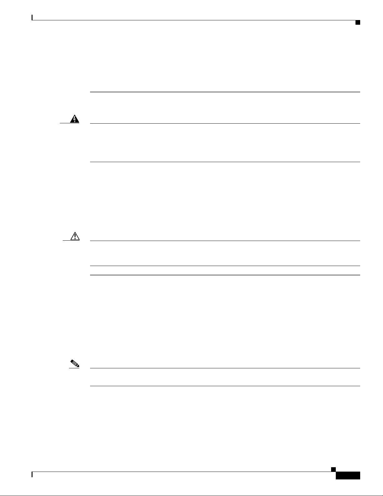
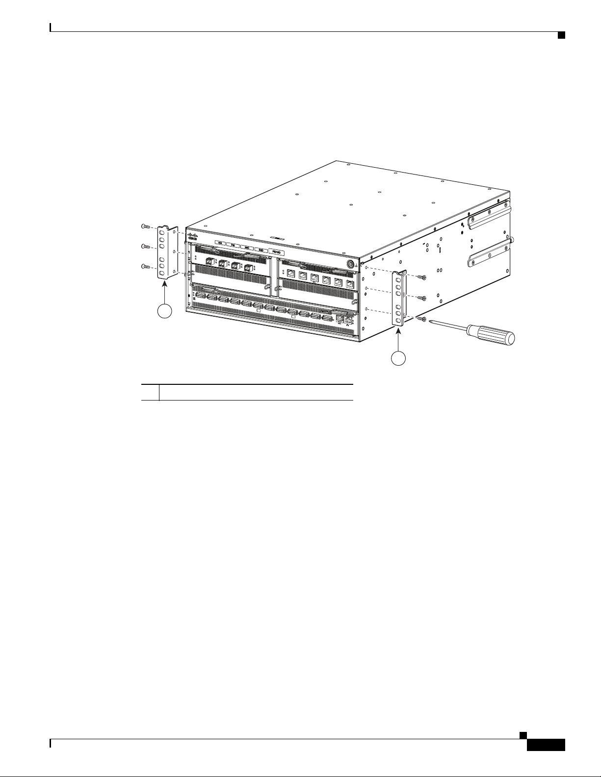
Step 2 Attach the two rack ear brackets to the power-fan module end of the chassis using a Phillips screwdriver and
the six M4 x 8 mm flat-head screws provided (three on each side), as shown in Figure 1. Firmly tighten the
screws on the rack ear brackets to secure them to the chassis.
Figure 1 Attaching the Rack Ear Brackets at the Power-Fan Module End
SFS3500
Series
IN
P
U
T
F
A
N
O
O
K
U
T
P
U
T
O
K
F
A
I
L
A
L
L
F
A
S
T
E
NER
F
U
S
M
L
L
U
Y
E
S
T
N
G
A
O
G
P
E
E
D
R
P
A
R
T
IO
I
O
N
R
O
F
P
O
W
E
R
S
U
1
0
0
-2
4
0
V
8
-4
!
C
A
U
T
IO
N
: D
IS
C
1
O
A
5
0
/6
0
H
N
N
z
E
C
T
P
OW
E
R
B
E
F
O
R
E
S
E
R
V
IC
IN
G
SFS3500
Series
IN
P
U
T
F
A
N
O
O
K
U
TP
U
T
O
K
F
A
I
L
B
E
T
O
P
P
L
Y
!
C
A
U
T
IO
N
: DIS
A
L
L
F
A
ST
E
N
E
R
F
U
S
MU
L
L
Y
E
S
T
N
B
G
E
A
O
G
P
E
ER
D
P
A
R
T
IO
I
O
N
R
O
T
O
F
P
O
W
ER
S
U
P
P
L
Y
1
0
0
-2
4
0
V
8
-4
A
5
0
/6
0
H
C
O
N
N
z
E
C
T
P
O
W
E
R
B
E
F
O
R
E S
E
R
V
I
C
IN
G
2
250376
1
1 Rack ear brackets 2 Guide rails (pre-attached)
Cisco SFS 3504 Multifabric Server Switch Installation and Configuration Note
6
78-18335-01
Page 7
Installing the Cisco SFS 3504 Server Switch
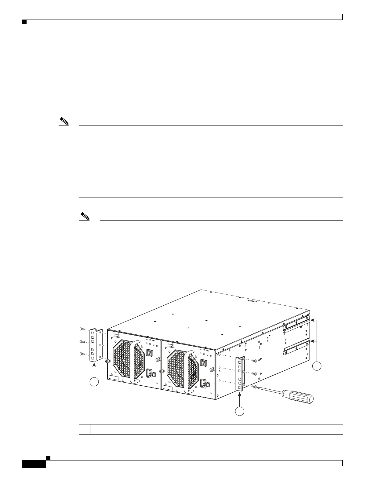
Step 3 Slide the Cisco SFS 3504 Server Switch between the rack posts (see Figure 2), until the rack ear brackets
on the front of the chassis make contact with the front rack posts.
Use four customer-supplied fasteners (two for each side) and the appropriate screwdriver (not included
in the accessory kit) to firmly secure the rack ear brackets to the front rack posts.
Note The handle on the AC power-fan module and/or the blanking panel can be used as an aid to
support the power-fan module side of the chassis during rack-mounting installation.
Figure 2 Sliding the Cisco SFS 3504 Server Switch Between Rack Posts and Inserting Brackets
SFS3500
Series
INPUT
FAN
OK
OUTPUT
OK
FAIL
ALL FASTENERS MUST
FULLY ENGA
OPERA
GED PRI
TION OF POWER SUPP
100-240V
ION: DISCONNECT PO
8-4A
50/60
Hz
WER BEFOR
E SERVICING
!
CAUT
SFS3500
Series
INPUT
FAN
OK
OUTPUT
OK
FAI
L
BE
OR
TO
LY
!
CAUT
ION: DISCONNECT POWER BEFORE S
ALL F
AST
ENERS MUST
FULL
Y EN
BE
GAGED PRIOR TO
OPE
RAT
ION OF P
OWER SUP
PLY
100-240V
8-4A
50/60H
z
ERVI
CING
241649
Step 4
Slide the two adjustable brackets, from the back, between each of the guide rails that are attached on
either side of the Cisco SFS 3504 Server Switch at the data connection end. (See Figure 2.)
Step 5 Adjust the adjustable brackets so that the holes in the brackets align with the holes in the rack posts, and
secure the brackets to the rack posts. (See Figure 2.)
Use four standard rack screws (two for each bracket; rack screws not included in the accessory kit) to
secure the adjustable brackets to the rear rack posts.
78-18335-01
Cisco SFS 3504 Multifabric Server Switch Installation and Configuration Note
7
Page 8
Installing the Cisco SFS 3504 Server Switch
Note The least amount of protrusion for the adjustable brackets must be 1/2 inch beyond the inside end of the
guide rail. The adjustable bracket should always be fully supported by the guide rails.
Installing with the Data Connection Cables Flush-front
To install the Cisco SFS 3504 Server Switch on a rack so that the data connection cables are flush-front
on the rack posts, perform the following steps:
Step 1 Open the bag that contains the mounting hardware.
Note To mount a Cisco SFS 3504 Server Switch on a rack, use eight screws and eight rack nuts. These
must be supplied by the customer, based upon the compatibility of the screws and nuts with the
specific racks.
Step 2 Remove the two guide rails that are attached to either side of the Cisco SFS 3504 Server Switch at the
data-connection end, and attach the guide rails similarly at the power-fan modules end. (See Figure 3.)
Use a Phillips screwdriver to unscrew the guide rails, and secure them at the new locations with the
screws that you just removed.
Figure 3 Attaching Guide Rails at the Power-Fan Module End
1
S
FS
350
0 S
eries FC
G
atew
ay
!
1
2
OK
Fault
3
Link
!
1
O
K
2
D
4
3
4
5
6
Cisco SFS3504 Multifa
S
F
S
3
5
0
0
S
e
rie
s
E
th
e
rn
et G
a
te
w
a
y
1
!
O
K
7
8
9
bric Switch
2
3
4
5
T
X
/
R
X
L
in
k
1
0
0
/1
0
0
0
B
1
0
6
a
s
e
T
1
1
1
2
T
X
/R
X
L
in
k
1
1
250430
1 Guide rails
Cisco SFS 3504 Multifabric Server Switch Installation and Configuration Note
8
78-18335-01
Page 9
Installing the Cisco SFS 3504 Server Switch
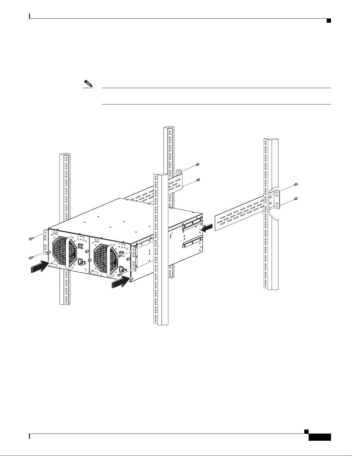
Step 3 Attach the two rack ear brackets to the data-connection end of the chassis using a Phillips screwdriver
and the six M4 x 8 mm screws provided (three for each bracket), as shown in Figure 4. Use the three
holes of the rack ear brackets. Firmly tighten the screws on the rack ear brackets to secure them to the
chassis.
Figure 4 Attaching the Rack Ear Brackets to the Data Connection End
SFS
350
0 Series FC
G
atew
ay
!
1
2
OK
Fault
3
Link
!
1
O
K
2
D
4
3
4
5
6
1
Cisco SFS3504 Multifa
bri
c Sw
S
F
S
3
5
0
0
S
e
rie
s
E
th
ern
e
t G
a
te
w
a
y
1
!
2
O
K
itch
3
4
5
T
X
/
R
X
L
in
k
10
0/10
0
0B
6
a
se
T
250431
7
8
9
1
0
1
1
1
2
T
X
/R
X
L
in
k
Step 4
1
1 Rack ear brackets
Slide the Cisco SFS 3504 Server Switch between the rack posts (see Figure 5) until the rack ear brackets
on the chassis make contact with the front rack posts. Use four customer-supplied fasteners (two for each
side) and the appropriate screwdriver (not included in the accessory kit) to firmly secure the rack ear
brackets to the front rack posts.
78-18335-01
Cisco SFS 3504 Multifabric Server Switch Installation and Configuration Note
9
Page 10

Installing the Cisco SFS 3504 Server Switch
Figure 5 Sliding the Cisco SFS 3504 Server Switch Between Rack Posts and Inserting Brackets
SFS3
500 Series FC
Gatew
ay
!
1
O
K
2
F
au
lt
3
Link
4
!
1
O
K
2
D
3
4
5
6
Cisc
o SFS3504 Mul
S
F
S
3
50
0
S
e
rie
!
OK
7
8
tifabric S
witc
s
Eth
e
rn
e
t
G
a
te
w
a
y
1
2
9
h
3
4
5
T
X
/R
X
L
in
k
6
100/1000B
ase T
1
0
1
1
1
2
T
X
/RX
L
in
k
241650
Step 5
Slide the two adjustable brackets, from the back, between each of the guide rails that are attached on
either side of the Cisco SFS 3504 Server Switch at the power-fan modules end. (See Figure 5.)
Step 6 Adjust the adjustable brackets so that the holes in the brackets align with the holes in the rack posts, and
secure the adjustable brackets to the rack posts. (See Figure 5.)
Use four standard rack screws (two for each bracket; rack screws not included in the accessory kit) to
secure the adjustable brackets to the rear rack posts.
10
Cisco SFS 3504 Multifabric Server Switch Installation and Configuration Note
78-18335-01
Page 11

Verifying the Installation
To verify your installation and configure basic connectivity, you must power-on the
Cisco SFS 3504 Server Switch and configure it through the serial console port from a terminal or
workstation.
Verifying the Installation
Warning
Hazardous voltage or energy is present on the backplane when the system is operating. Use caution
when servicing.
Statement 1034
To verify the installation of your Cisco SFS 3504 Server Switch, perform the following steps:
Step 1 Use the serial cable (provided) to connect the serial console port of the InfiniBand switch card in slot 5
of your Cisco SFS 3504 Server Switch to a terminal or to a workstation that runs terminal-emulation
software.
Step 2 Launch a terminal session with the following parameters
• Baud: 9600 bps
• Data Bits: 8
• Parity: None
• Stop Bits: 1
• Flow Control: None
Step 3 Connect a power cord to your Cisco SFS 3504 Server Switch, and then plug the cord into an appropriate
power source. The Cisco SFS 3504 Server Switch boots.
Step 4 After the system boots, press the Enter key several times to display the CLI login prompt.
Login:
Step 5 Enter super as your user ID and password to log in as a user with administrative privileges.
Login: super
Password: super
SFS-3504>
78-18335-01
Cisco SFS 3504 Multifabric Server Switch Installation and Configuration Note
11
Page 12

Configuring the Cisco SFS 3504 Server Switch
Step 6 Enter the show card command to verify that the switch is operational and that the system acknowledges
the new module and has brought it online. If the output of the show card command shows the oper code
as “normal” and boot status as “success,” as shown in the example below, proceed to the next step in
configuring the switch.
SFS-3504> show card
================================================================================
Card Information
================================================================================
admin oper admin oper oper
slot type type status status code
-------------------------------------------------------------------------------2 fc4port4G fc4port4G up up normal
5* controllerIb12port4xDDR controllerIb12port4xDDR up up normal
================================================================================
Card Boot Information
================================================================================
boot boot boot
slot stage status image
-------------------------------------------------------------------------------2 done success image-a:SFS_OS-2.10.0/build585
5 done success image-a:SFS_OS-2.10.0/build585
================================================================================
Card Seeprom
================================================================================
product pca pca fru
slot serial-number serial-number number number
-------------------------------------------------------------------------------2 JBL07014804 JBL07014804 73-11051-02 68-2893-01
5 JAB111902Y9 JAB111902Y9 73-11049-02 68-2890-02
If the output of the show card command shows otherwise, enter the show diagnostic ? command to
determine whether or not a hardware failure has occurred. If the output shows a hardware failure, contact
your Cisco technical support representative.
Configuring the Cisco SFS 3504 Server Switch
This section assumes that you have verified the installation. At the end of the verification process, the
Cisco SFS 3504 Server Switch automatically obtains the IP address from Dynamic Host Configuration
Protocol (DHCP) if the DHCP server is configured. This section describes how to configure the
Cisco SFS 3504 Server Switch and includes the following topics:
• Obtaining an IP Address from the DHCP Server for Ethernet Management, page 13
• Configuring a Static IP Address for Ethernet Management, page 13
• Configuring the System Clock, page 17
12
• Configuring an NTP Server, page 18
• Launching the Chassis Manager (Optional GUI Interface), page 19
• Installing the Element Manager GUI (Optional), page 20
Cisco SFS 3504 Multifabric Server Switch Installation and Configuration Note
78-18335-01
Page 13

Configuring the Cisco SFS 3504 Server Switch
Obtaining an IP Address from the DHCP Server for Ethernet Management
This section describes how to obtain an IP address from the DHCP server by default.
Note DHCP is enabled by default on the Cisco SFS 3504 Server Switch.
To obtain an IP address using the default enabled DHCP, you must obtain the MAC address. The MAC
address is printed on a label on your Cisco SFS 3504 Server Switch in the following format:
AA:BB:CC:DD:EE.
Use the MAC address to configure your DHCP server to allocate an IP address of your choice to the
SFS 3504 switch management interface. Otherwise, the DHCP server (if present) allocates the first
available IP address from the designated pool of addresses. In the latter case you can find out which
address was allocated by logging in to the CLI on the serial console and entering the show interface
mgmt-eth command. See the Cisco SFS Product Family Command Reference for additional details
about CLI commands.
Use the IP address, to Telnet to the Cisco SFS 3504 Server Switch and perform tasks such as configuring
the system clock and configuring an NTP server as described in the “Configuring the System Clock”
section on page 17 and “Configuring an NTP Server” section on page 18.
Configuring a Static IP Address for Ethernet Management
Note If a DHCP server is not available, then use this method to configure an IP address.
To configure a static IP address for an Ethernet Management interface, you must first connect the serial
console port. You can connect the serial console port to a PC serial port for local administrative access
to the Cisco SFS 3504 Server Switch. A terminal emulation software product, such as HyperTerminal,
makes communication between the Cisco SFS 3504 Server Switch and your PC possible during setup
and configuration.
To connect the console port to a PC, perform the following steps:
Step 1 Connect the cable from the serial console port on the controller module, located on the rear panel of the
Cisco SFS 3504 Server Switch, to your terminal or management workstation. Use the straight-through
M/F serial cable, which is provided in the package.
Step 2 Open a terminal emulation window using a program such as Hyper-Terminal for Windows.
Step 3 Configure the baud rate and character format of the PC terminal emulation program to match the
following management port default characteristics:
• Baud: 9600 bps
• Data Bits: 8
• Parity: None
78-18335-01
• Stop Bits: 1
Step 4 Connect the supplied DB-9/RJ-45 female adapter or DB-25/RJ-45 female adapter (depending on your
PC connection) to the PC serial port.
Cisco SFS 3504 Multifabric Server Switch Installation and Configuration Note
13
Page 14

Configuring the Cisco SFS 3504 Server Switch
Step 5 Connect one end of the supplied console cable (a flat rollover RJ-45 to RJ-45 cable) to the serial console
port. Connect the other end to the DB-9/RJ-45 female adapter or DB-25/RJ-45 adapter at the PC serial
port.
After you connect the serial console port, you may configure a static IP address for the Ethernet
management interface by performing the following steps:
Step 1 Wait for the login prompt.
Login:
Step 2 Enter the username and password. The default username is super, and the default password is super.
Login: super
Password: super
SFS-3504>
Step 3 Enter the enable command to enter privileged EXEC mode:
SFS-3504> enable
SFS-3504#
Step 4 Enter the configure command to enter configuration mode:
SFS-3504# configure
SFS-3504(config)#
Step 5 Enter the interface mgmt-ethernet command to enter the config-if-mgmt-ethernet mode:
SFS-3504(config)# interface mgmt-ethernet
SFS-3504(config-if-mgmt-ethernet)#
Step 6 Enable the static address option, which turns off the default-enabled DHCP:
SFS-3504(config)# address-option static
Step 7 Enter the IP address of the management interface, followed by the netmask, which enables the optional
static address:
SFS-3504(config-if-mgmt-ethernet)# ip address ip_address netmask
Step 8 Set the default gateway for the management interface. See your system administrator for a gateway
address.
SFS-3504(config-if-mgmt-ethernet)# gateway ip_address
Step 9 Enable the management interface by entering the no shutdown command:
SFS-3504(config-if-mgmt-ethernet)# no shutdown
Step 10 Return to privileged EXEC mode by entering the exit command twice, and save the configuration to
preserve it between reboots by entering the copy running-config startup-config
SFS-3504(config-if-mgmt-ethernet)# exit
SFS-3504(config)# exit
SFS-3504# copy running-config startup-config
command:
14
Cisco SFS 3504 Multifabric Server Switch Installation and Configuration Note
78-18335-01
Page 15

Connecting InfiniBand Hosts
This section provides a brief overview for connecting your IB hosts. For detailed instructions, see the
documentation for the specific HCA.
Use IB cables to connect the HCA in your host to the IB switch module of your Cisco SFS 3504 Server
Switch. To insert an IB cable with a pinch connector, pinch both sides of the back of the connector, and
push the connector into the interface. (See Figure 6.)
Figure 6 InfiniBand Cable with Pinch Connector
Configuring the Cisco SFS 3504 Server Switch
10
144960
To insert an IB with a pull connector, push the connector into the interface, and push the latch until it is
engaged after it is in the interface. An alternative method of plugging in a pull connector IB cable is to
push the latch first, and then insert the connector until you hear a click. (See Figure 7.)
Figure 7 InfiniBand Cable with Pull Connector
250386
78-18335-01
Cisco SFS 3504 Multifabric Server Switch Installation and Configuration Note
15
Page 16

Configuring the Cisco SFS 3504 Server Switch
Note If your host does not provide enough free space around a given IB port, verify that your IB cable
connector engages completely. Wiggle your connector back and forth to be sure that both sides of the
connector have locked firmly into place.
To remove a cable with a pinch connector, pinch both sides of the back of the connector, and pull the
connector away from the port. (See Figure 8.)
Figure 8 Removing a Pinch Connector
Press here
Press here
250387
To remove a cable with a pull connector, grasp the connector with one hand, push it toward the port, and
then pull the latch away from the port with your other hand while gently wiggling the connector away
from the port. (See Figure 9.)
Figure 9 Removing a Pull Connector
Hold here
Pull here
Hold here
250388
16
Cisco SFS 3504 Multifabric Server Switch Installation and Configuration Note
78-18335-01
Page 17

Configuring the System Clock
You can configure the system clock to show the time, date, and time zone, and you can configure daylight
savings time, if appropriate for your location. For more information, see the Cisco SFS Product Family
Command Reference.
Setting the System Clock
To set the system clock, perform the following steps:
Step 1 Enter the enable command to enter privileged EXEC mode:
SFS-3504> enable
SFS-3504#
Step 2 Enter the clock set command with the time (hour, minute, and second) and date (day, month, year) that
you want to apply, as shown in this example which sets the time to 7:22 PM and 10 seconds on the
25th of May, 2015:
SFS-3504# clock set 19:22:10 25 05 15
Configuring the Cisco SFS 3504 Server Switch
Step 3 Save the configuration to preserve it between reboots by entering the copy running-config
startup-config command:
SFS-3504# copy running-config startup-config
Setting the Time Zone
To define and set the time zone on your server switch, perform the following steps:
Step 1 Enter the enable command to enter privileged EXEC mode:
SFS-3504> enable
SFS-3504#
Step 2 Enter the configure command to enter configuration mode:
SFS-3504# configure
SFS-3504(config)#
Step 3 Enter clock timezone command. The following example shows setting the time zone to Pacific Standard
Time.
SFS-3504(config)# clock timezone PST 8 0
Step 4 Save the configuration to preserve it between reboots by entering the copy running-config
startup-config command:
SFS-3504(config)# exit
SFS-3504# copy running-config startup-config
78-18335-01
Cisco SFS 3504 Multifabric Server Switch Installation and Configuration Note
17
Page 18

Configuring the Cisco SFS 3504 Server Switch
Setting Daylight Savings Time
To configure daylight savings time, perform the following steps:
Step 1 Enter the enable command to enter privileged EXEC mode:
SFS-3504> enable
SFS-3504#
Step 2 Enter the configure command to enter configuration mode:
SFS-3504# configure
SFS-3504(config)#
Step 3 Enter clock summer-time command:
SFS-3504(config)# clock summer-time
Step 4 Save the configuration to preserve it between reboots by entering the exit command to return to
privileged EXEC mode and by entering the copy running-config startup-config command:
SFS-3504(config)# exit
SFS-3504# copy running-config startup-config
To undo the daylight savings time configuration and revert to standard local time, use the no form of the
clock summer-time command.
Configuring an NTP Server
To configure your Cisco SFS 3504 Server Switch to obtain time and date information from a Network
Time Protocol (NTP) server you must assign an NTP server. To assign an NTP server, perform the
following steps:
Step 1 Enter the enable command to enter privileged EXEC mode.
SFS-3504> enable
SFS-3504#
Step 2 Enter the configure command to enter configuration mode.
SFS-3504# configure
SFS-3504(config)#
Step 3 Enter the ntp command with the server-one keyword and the IP address of the primary NTP server, as
shown in the following example:
SFS-3504(config)# ntp server-one 10.2.0.50
18
For more information, see the Cisco SFS Product Family Command Reference.
Step 4 Save the configuration to preserve it between reboots by entering the copy running-config startup-config
command:
SFS-3504(config)# exit
SFS-3504# copy running-config startup-config
Cisco SFS 3504 Multifabric Server Switch Installation and Configuration Note
78-18335-01
Page 19

Configuring the Cisco SFS 3504 Server Switch
Launching the Chassis Manager (Optional GUI Interface)
Chassis Manager is a web-based GUI that can be used to manage a single InfiniBand chassis.
To launch Chassis Manager, perform the following steps:
Step 1 Launch your web browser. Chassis Manager supports the following browsers:
• Microsoft Internet Explorer Version 6 or later
• Netscape Navigator Version 6 or later
• Mozilla Version 1.4 or later
Step 2 Type the management IP address of your server switch in the address field of your browser, and press
Enter. For details about obtaining a management IP address, see the “Obtaining an IP Address from the
DHCP Server for Ethernet Management” section on page 13.
A log-in window opens. (See Figure 10.)
Figure 10 Chassis Manager Log-In Window
Step 3
Enter your username and password in the log-in window, and click Login. The default username and
password are super and super.
The Chassis Manager loads in your browser window. (See Figure 11.) The ports that are operational in
DDR speed are highlighted in your browser window in orange, and the other ports are operational as
SDR ports. When the ports are operationally down, they are gray in color. (The example in Figure 11
shows ports 1 and 7 in orange as DDR ports.)
78-18335-01
Cisco SFS 3504 Multifabric Server Switch Installation and Configuration Note
19
Page 20

Configuring the Cisco SFS 3504 Server Switch
Figure 11 Chassis Manager
For more information about Chassis Manager, see the Cisco SFS Product Family Chassis Manager User
Guide.
Installing the Element Manager GUI (Optional)
Element Manager runs on Linux, Solaris, and Windows platforms. Follow installation instructions for
the appropriate platform. For more information about the Element Manager tasks, see the Cisco SFS
Product Family Element Manager User Guide.
To install Element Manager, your system must meet the following requirements:
• 64 MB of available RAM
• 75 MB of available hard disk space and 50 MB of additional available hard disk space during
installation
• 300-MHz processor
• 800 x 600 screen resolution with 16-bit color depth
Cisco SFS 3504 Multifabric Server Switch Installation and Configuration Note
20
78-18335-01
Page 21

Linux Installation
Step 1 Log in to your Linux host.
Step 2 Download the Element Manager software from the Cisco Software Download Center:
Step 3 Navigate to the Linux directory of the downloaded software.
Step 4 Locate the Linux files, choose the installer that is appropriate for your program, and proceed with the
Solaris Installation
Step 1 Log in to your Solaris host.
Configuring the Cisco SFS 3504 Server Switch
To install Element Manager on Linux, perform the following steps:
http://www.cisco.com/public/sw-center/
installation wizard.
To install Element Manager on Solaris, perform the following steps:
Step 2 Download the Element Manager software from the Cisco Software Download Center:
http://www.cisco.com/public/sw-center/
Step 3 Navigate to the em/Solaris directory of the downloaded software.
Step 4 Start the install_solaris_sparc.bin file. Proceed with the installation wizard.
Windows Installation
To install Element Manager on Windows, perform the following steps:
Step 1 Log in to your Windows host.
Step 2 Download the Element Manager software from the Cisco Software Download Center:
http://www.cisco.com/public/sw-center/
Step 3 Navigate to the Windows directory of the downloaded software.
Step 4 Launch the executable file (install_x86.exe) to begin the installation process.
The Introduction screen appears.
Step 5 Click Next.
The License Agreement screen appears.
Step 6 Read the license agreement, choose I accept the terms of the license agreement, and then click Next.
78-18335-01
The Choose Install Folder screen appears.
Step 7 Select a folder, and then click Next.
The Choose Shortcut Folder screen appears.
Cisco SFS 3504 Multifabric Server Switch Installation and Configuration Note
21
Page 22

Connecting the 10/100 Ethernet Management Port
Step 8 Make selections as appropriate for your needs, and then click Next.
The Pre-Installation Summary screen appears.
Step 9 Verify installation information in the Please Review the Following Before Continuing window, and then
click Install.
Step 10 The installation executes.
Step 11 Click Done when the installation completes.
Connecting to Element Manager
Factory defaults permit your server switch to connect to Element Manager. No configuration is
necessary.
To connect to Element Manager, perform the following steps:
Step 1 Launch Element Manager. The Open Device - SFS Element Manager window appears.
Step 2 In the Device Name or IP Address field, enter the IP address or the network name of the device that you
want to manage.
Step 3 In the SNMP Community field, enter this community string: private.
Step 4 Click Open to establish a connection.
Connecting the 10/100 Ethernet Management Port
The autosensing 10/100 Ethernet management port is located on the rear panel/port connectors side of
the Cisco SFS 3504 Server Switch. The Ethernet management port is used for out-of-band management
of the Cisco SFS 3504 Server Switch.
Use the CAT-5 twisted pair RJ-45 straight-through cable to connect the 10/100 Ethernet management
port to external hubs, switches, and routers.
Troubleshooting
For all customers, partners, resellers, and distributors who hold valid Cisco service contracts, Cisco
Technical Support provides 24-hour technical assistance. The Cisco Technical Support Website on
Cisco.com features extensive online support resources. In addition, Cisco Technical Assistance Center
(TAC) engineers provide telephone support. If you do not hold a valid Cisco service contract, contact
your reseller.
22
Cisco SFS 3504 Multifabric Server Switch Installation and Configuration Note
78-18335-01
Page 23

Managing the Cisco SFS 3504 Server Switch
You can manage the Cisco SFS 3504 Server Switch by using one of the following methods:
• Command-line interface (CLI)—a text-based interface accessible through a direct serial connection,
Telnet over IP, or SSH over IP.
• Element Manager (GUI)—A graphical interface installed on a workstation, accessible over IP.
• Chassis Manager (GUI)—A graphical interface that you access with a web browser.
For additional details, see the Cisco SFS Product Family Command Reference, the Cisco SFS Product
Family Element Manager User Guide, or the Cisco SFS Product Family Chassis Manager User Guide.
Safety Warning Translation
This section repeats, in multiple languages, the basic safety warning definition appropriate for the
Cisco SFS 3504 Multifabric Server Switch.
Statement 1071—Warning Definition
Managing the Cisco SFS 3504 Server Switch
Warning
Waarschuwing
IMPORTANT SAFETY INSTRUCTIONS
This warning symbol means danger. You are in a situation that could cause bodily injury. Before you
work on any equipment, be aware of the hazards involved with electrical circuitry and be familiar
with standard practices for preventing accidents. Use the statement number provided at the end of
each warning to locate its translation in the translated safety warnings that accompanied this
device.
SAVE THESE INSTRUCTIONS
BELANGRIJKE VEILIGHEIDSINSTRUCTIES
Dit waarschuwingssymbool betekent gevaar. U verkeert in een situatie die lichamelijk letsel kan
veroorzaken. Voordat u aan enige apparatuur gaat werken, dient u zich bewust te zijn van de bij
elektrische schakelingen betrokken risico's en dient u op de hoogte te zijn van de standaard
praktijken om ongelukken te voorkomen. Gebruik het nummer van de verklaring onderaan de
waarschuwing als u een vertaling van de waarschuwing die bij het apparaat wordt geleverd, wilt
raadplegen.
BEWAAR DEZE INSTRUCTIES
78-18335-01
Cisco SFS 3504 Multifabric Server Switch Installation and Configuration Note
23
Page 24

Safety Warning Translation
Varoitus
Attention
Warnung
TÄRKEITÄ TURVALLISUUSOHJEITA
Tämä varoitusmerkki merkitsee vaaraa. Tilanne voi aiheuttaa ruumiillisia vammoja. Ennen kuin
käsittelet laitteistoa, huomioi sähköpiirien käsittelemiseen liittyvät riskit ja tutustu
onnettomuuksien yleisiin ehkäisytapoihin. Turvallisuusvaroitusten käännökset löytyvät laitteen
mukana toimitettujen käännettyjen turvallisuusvaroitusten joukosta varoitusten lopussa näkyvien
lausuntonumeroiden avulla.
SÄILYTÄ NÄMÄ OHJEET
IMPORTANTES INFORMATIONS DE SÉCURITÉ
Ce symbole d'avertissement indique un danger. Vous vous trouvez dans une situation pouvant
entraîner des blessures ou des dommages corporels. Avant de travailler sur un équipement, soyez
conscient des dangers liés aux circuits électriques et familiarisez-vous avec les procédures
couramment utilisées pour éviter les accidents. Pour prendre connaissance des traductions des
avertissements figurant dans les consignes de sécurité traduites qui accompagnent cet appareil,
référez-vous au numéro de l'instruction situé à la fin de chaque avertissement.
CONSERVEZ CES INFORMATIONS
WICHTIGE SICHERHEITSHINWEISE
Dieses Warnsymbol bedeutet Gefahr. Sie befinden sich in einer Situation, die zu Verletzungen führen
kann. Machen Sie sich vor der Arbeit mit Geräten mit den Gefahren elektrischer Schaltungen und
den üblichen Verfahren zur Vorbeugung vor Unfällen vertraut. Suchen Sie mit der am Ende jeder
Warnung angegebenen Anweisungsnummer nach der jeweiligen Übersetzung in den übersetzten
Sicherheitshinweisen, die zusammen mit diesem Gerät ausgeliefert wurden.
Avvertenza
Advarsel
BEWAHREN SIE DIESE HINWEISE GUT AUF.
IMPORTANTI ISTRUZIONI SULLA SICUREZZA
Questo simbolo di avvertenza indica un pericolo. La situazione potrebbe causare infortuni alle
persone. Prima di intervenire su qualsiasi apparecchiatura, occorre essere al corrente dei pericoli
relativi ai circuiti elettrici e conoscere le procedure standard per la prevenzione di incidenti.
Utilizzare il numero di istruzione presente alla fine di ciascuna avvertenza per individuare le
traduzioni delle avvertenze riportate in questo documento.
CONSERVARE QUESTE ISTRUZIONI
VIKTIGE SIKKERHETSINSTRUKSJONER
Dette advarselssymbolet betyr fare. Du er i en situasjon som kan føre til skade på person. Før du
begynner å arbeide med noe av utstyret, må du være oppmerksom på farene forbundet med
elektriske kretser, og kjenne til standardprosedyrer for å forhindre ulykker. Bruk nummeret i slutten
av hver advarsel for å finne oversettelsen i de oversatte sikkerhetsadvarslene som fulgte med denne
enheten.
TA VARE PÅ DISSE INSTRUKSJONENE
24
Cisco SFS 3504 Multifabric Server Switch Installation and Configuration Note
78-18335-01
Page 25

Safety Warning Translation
Aviso
¡Advertencia!
Varning!
INSTRUÇÕES IMPORTANTES DE SEGURANÇA
Este símbolo de aviso significa perigo. Você está em uma situação que poderá ser causadora de
lesões corporais. Antes de iniciar a utilização de qualquer equipamento, tenha conhecimento dos
perigos envolvidos no manuseio de circuitos elétricos e familiarize-se com as práticas habituais de
prevenção de acidentes. Utilize o número da instrução fornecido ao final de cada aviso para
localizar sua tradução nos avisos de segurança traduzidos que acompanham este dispositivo.
GUARDE ESTAS INSTRUÇÕES
INSTRUCCIONES IMPORTANTES DE SEGURIDAD
Este símbolo de aviso indica peligro. Existe riesgo para su integridad física. Antes de manipular
cualquier equipo, considere los riesgos de la corriente eléctrica y familiarícese con los
procedimientos estándar de prevención de accidentes. Al final de cada advertencia encontrará el
número que le ayudará a encontrar el texto traducido en el apartado de traducciones que acompaña
a este dispositivo.
GUARDE ESTAS INSTRUCCIONES
VIKTIGA SÄKERHETSANVISNINGAR
Denna varningssignal signalerar fara. Du befinner dig i en situation som kan leda till personskada.
Innan du utför arbete på någon utrustning måste du vara medveten om farorna med elkretsar och
känna till vanliga förfaranden för att förebygga olyckor. Använd det nummer som finns i slutet av
varje varning för att hitta dess översättning i de översatta säkerhetsvarningar som medföljer denna
anordning.
SPARA DESSA ANVISNINGAR
78-18335-01
Cisco SFS 3504 Multifabric Server Switch Installation and Configuration Note
25
Page 26

Safety Warning Translation
Aviso
Advarsel
INSTRUÇÕES IMPORTANTES DE SEGURANÇA
Este símbolo de aviso significa perigo. Você se encontra em uma situação em que há risco de lesões
corporais. Antes de trabalhar com qualquer equipamento, esteja ciente dos riscos que envolvem os
circuitos elétricos e familiarize-se com as práticas padrão de prevenção de acidentes. Use o
número da declaração fornecido ao final de cada aviso para localizar sua tradução nos avisos de
segurança traduzidos que acompanham o dispositivo.
GUARDE ESTAS INSTRUÇÕES
VIGTIGE SIKKERHEDSANVISNINGER
Dette advarselssymbol betyder fare. Du befinder dig i en situation med risiko for
legemesbeskadigelse. Før du begynder arbejde på udstyr, skal du være opmærksom på de
involverede risici, der er ved elektriske kredsløb, og du skal sætte dig ind i standardprocedurer til
undgåelse af ulykker. Brug erklæringsnummeret efter hver advarsel for at finde oversættelsen i de
oversatte advarsler, der fulgte med denne enhed.
GEM DISSE ANVISNINGER
26
Cisco SFS 3504 Multifabric Server Switch Installation and Configuration Note
78-18335-01
Page 27

Safety Warning Translation
78-18335-01
Cisco SFS 3504 Multifabric Server Switch Installation and Configuration Note
27
Page 28

Safety Warning Translation
28
Cisco SFS 3504 Multifabric Server Switch Installation and Configuration Note
78-18335-01
Page 29

Related Documentation
Related Documentation
For additional information about the Cisco SFS 3504 Server Switch and command-line interface (CLI)
commands, see the following documentation:
• Regulatory Compliance and Safety Information for the Cisco Server Fabric Switches: 7000D,
7000P, 7008P, 7012, 7024, 3012R, and 3504
• Cisco SFS 3504 Multifabric Server Switch Installation Guide
• Cisco SFS Product Family Command Reference
• Cisco SFS Product Family Element Manager User Guide
• Cisco SFS Product Family Chassis Manager User Guide
• Cisco Server Fabric Switches Rack Shelf Kit Installation Guide
• Cisco SFS InfiniBand Software Configuration Guide
Obtaining Documentation, Obtaining Support, and Security Guidelines
For information on obtaining documentation, obtaining support, providing documentation feedback,
security guidelines, and also recommended aliases and general Cisco documents, see the monthly
What’s New in Cisco Product Documentation, which also lists all new and revised Cisco technical
documentation, at:
http://www.cisco.com/en/US/docs/general/whatsnew/whatsnew.html
78-18335-01
Cisco SFS 3504 Multifabric Server Switch Installation and Configuration Note
29
Page 30

Obtaining Documentation, Obtaining Support, and Security Guidelines
30
This document is to be used in conjunction with the documents listed in the “Related Documentation” section.
CCSP, CCVP, the Cisco Square Bridge logo, Follow Me Browsing, and StackWise are trademarks of Cisco Systems, Inc.; Changing the Way We Work,
Live, Play, and Learn, and iQuick Study are service marks of Cisco Systems, Inc.; and Access Registrar, Aironet, BPX, Catalyst, CCDA, CCDP,
CCIE, CCIP, CCNA, CCNP, Cisco, the Cisco Certified Internetwork Expert logo, Cisco IOS, Cisco Press, Cisco Systems, Cisco Systems Capital,
the Cisco Systems logo, Cisco Unity, Enterprise/Solver, EtherChannel, EtherFast, EtherSwitch, Fast Step, FormShare, GigaDrive, GigaStack, HomeLink,
Internet Quotient, IOS, IP/TV, iQ Expertise, the iQ logo, iQ Net Readiness Scorecard, LightStream, Linksys, MeetingPlace, MGX, the Networkers logo,
Networking Academy, Network Registrar, Pack e t, PIX, Post-Routing, Pre-Routing, ProConnect, RateMUX, ScriptShare, SlideCast, SMARTnet,
The Fastest Way to Increase Your Internet Quotient, and TransPath are registered trademarks of Cisco Systems, Inc. and/or its affiliates in the
United States and certain other countries.
All other trademarks mentioned in this document or Website are the property of their respective owners. The use of the word partner does not imply a
partnership relationship between Cisco and any other company. (0601R)
© 2007 Cisco Systems, Inc. All rights reserved.
Cisco SFS 3504 Multifabric Server Switch Installation and Configuration Note
78-18335-01
 Loading...