

Cisco SGE2000 - Cisco - Gigabit Switch, SGE2000P, SGE2010, SFE2010, SFE2000 Administration Manual
Page 1
Cisco Small Business
SFE/SGE Managed Switches
ADMINISTRATION
GUIDE
Page 2

6bZg^XVh=ZVYfjVgiZgh
8^hXdHnhiZbh!>cX#
HVc?dhZ!86
6h^VEVX^[^X=ZVYfjVgiZgh
8^hXdHnhiZbhJH6EiZ#AiY#
H^c\VedgZ
:jgdeZ=ZVYfjVgiZgh
8^hXdHnhiZbh>ciZgcVi^dcVa7K
6bhiZgYVb!I]ZCZi]ZgaVcYh
8^hXd]VhbdgZi]Vc '%%d[[^XZhldgaYl^YZ#6YYgZhhZh! e]dcZcjbWZgh!VcY [VmcjbWZghVgZa^hiZYdc i]Z8^hXdLZWh^iZVilll#X^hXd#Xdb$\d$d[[^XZh#
889:!88:CI!8^hXd:dh!8^hXdAjb^c!8^hXdCZmjh!8^hXdHiVY^jbK^h^dc!8^hXdIZaZEgZhZcXZ!8^hXdLZW:m!i]Z8^hXdad\d!98:!VcYLZaXdbZidi]Z=jbVcCZildg`VgZigVYZbVg`h08]Vc\^c\i]ZLVnLZLdg` !
A^kZ!EaVn!VcYAZVgcVcY8^hXdHidgZVgZh Zgk^XZbVg`h0VcY6XX ZhhGZ\^higVg!6^gdcZi!6hncXDH!7g^c\^c\i]ZBZZi^c\IdNdj!8ViVanhi!8896!889E!88>:!88>E!88C6 !88CE!88HE!88KE!8^hXd!i]Z8^hXd8Zg i^[^ZY
>ciZgcZildg`:meZgiad\d!8^hXd>DH!8^hXdEgZhh!8^hXdHnhiZbh!8^hXdHnhiZbh8Ve^iVa!i]Z8^hXdHnhiZbhad\d!8^hX dJc^in!8daaVWdgVi^dcL^i]djiA^b^iVi^dc!:i]Zg;Vhi!:i]ZgHl^iX]!:kZci8ZciZg!;VhiHiZe!;daadlBZ
7gdlh^c\!;dgbH]VgZ!<^\V9g^kZ!=dbZA^c`!>ciZgcZiFjdi^Zci!>DH!^E]dcZ!^Fj^X`HijYn!>gdcEdgi!i]Z>gdcEdgiad\d!A^\]iHigZVb!A^c`hnh!BZY^VIdcZ!BZZi^c\EaVXZ!BZZi^c\EaVXZ8]^bZHdjcY!B<M!CZildg`Zgh!CZildg`^c\
6XVYZbn!CZildg`GZ \^higVg!E8Cdl!E>M!EdlZgEVcZah!Egd8dccZXi!HXg^eiH]VgZ!HZcYZg7VhZ!HB6GIcZi!HeZ Xigjb:meZgi!HiVX`L^hZ!I]Z;VhiZhiLVnid>cXgZVhZNdjg>ciZgcZiFjdi^Zci!IgVchEVi]!LZW:m!VcYi]ZLZW:m
ad\dVgZgZ\^hiZgZYigVYZbVg`hd[8^hXdHnhiZbh!>cX#VcY$dg^ihV[ [^a^ViZh^ci]ZJc^iZYHiViZhVcYXZgiV^cdi]ZgXdjcig^Zh#
6aadi]ZgigVYZbVg`hbZci^dcZY^ci]^hYdXjbZcidglZWh^iZVgZi]ZegdeZgind[i]Z^ggZheZ Xi^kZdlcZgh#I]ZjhZd[i]ZldgYeVgicZgYdZhcdi^beanVeVg icZgh]^egZaVi^dch]^eWZilZZc8^hXdVcYVcndi]ZgXdbeVcn#%-%.G
6bZg^XVh=ZVYfjVgiZgh
8^hXdHnhiZbh!>cX#
HVc?dhZ!86
6h^VEVX^[^X=ZVYfjVgiZgh
8^hXdHnhiZbhJH6EiZ#AiY#
H^c\VedgZ
:jgdeZ=ZVYfjVgiZgh
8^hXdHnhiZbh>ciZgcVi^dcVa7K
6bhiZgYVb!I]ZCZi]ZgaVcYh
© 2009 Cisco Systems, Inc. All rights reserved. OL-20139-01
Page 3

Contents
Contents
Chapter 1: Getting Started 1
Starting the Application 1
Understanding the Interface 3
Using the Cisco Management Buttons 5
Using Screen and Table Options 5
Adding Device Information 5
Modifying Device Information 6
Deleting Device Information 7
Logging Off of the Device 7
The About Page 7
Chapter 2: Managing Device Information 9
Defining System Information 9
Managing Stacking 11
Understanding Switch Operating Modes 11
Configuring a Stack 12
Stack Membership 14
Defining Stacking Unit ID 15
Adding, Replacing and Removing Stacking Members — Examples 21
Managing Stacks 23
Viewing Device Health 25
Resetting the Device 26
Defining Bonjour 27
Disabling Bonjour 29
TCAM Utilization 30
Chapter 3: Configuring System Time 33
Defining System Time 33
Defining SNTP Settings 36
Cisco Small Business SFE/SGE Managed Switches Administration Guide 1
Page 4

Contents
Defining SNTP Authentication 39
Chapter 4: Configuring Device Security 41
Passwords Management 41
Modifying the Local User Settings 43
Defining Authentication 44
Defining Profiles 44
Modifying an Authentication Profile 47
Mapping Authentication Profiles 48
Defining TACACS+ 50
Defining RADIUS 55
Defining Access Methods 60
Defining Access Profiles 61
Defining Profile Rules 65
Defining Traffic Control 72
Defining Storm Control 73
Defining Port Security 76
Defining 802.1X 80
Defining 802.1X Properties 81
Defining Port Authentication 82
Defining Authentication 87
Defining Authenticated Hosts 91
Defining Access Control 92
Defining MAC Based ACL 92
Defining IP Based ACL 100
Defining IPv6 Based ACLs 112
Defining ACL Binding 121
Defining DoS Prevention 123
Defining DHCP Snooping 127
Cisco Small Business SFE/SGE Managed Switches Administration Guide 2
DoS Global Settings 123
Defining Martian Addresses 125
Page 5

Contents
Defining DHCP Snooping Properties 128
Defining DHCP Snooping on VLANs 129
Defining Trusted Interfaces 130
Binding Addresses to the DHCP Snooping Database 132
Defining IP Source Guard 135
Defining Dynamic ARP Inspection 141
Defining ARP Inspection Properties 142
Defining ARP Inspection Trusted Interfaces 144
Defining ARP Inspection List 146
Assigning ARP Inspection VLAN Settings 148
Chapter 5: Configuring Ports 151
Configuring Ports Settings for Layer 2 Enabled Devices 151
Configuring Ports Settings for Layer 3 Enabled Devices 157
157
Chapter 6: Configuring VLANs 163
Defining VLAN Properties 164
Modifying VLANs 166
Defining VLAN Membership 167
Modifying VLAN Membership 169
Assigning Ports to Multiple VLANs 170
Defining GVRP Settings 173
Modifying GVRP Settings 174
Defining VLAN Interface Settings 176
Modifying VLAN Interface Settings 178
Defining Customer VLANs Using QinQ 180
Defining Multicast TV VLAN 181
Defining CPE VLAN Mapping 183
Defining Protocol Groups 184
Defining a Protocol Port 187
Cisco Small Business SFE/SGE Managed Switches Administration Guide 3
Page 6

Contents
Chapter 7: Configuring IP Information 190
IP Addressing 190
Managing IPv6 190
Viewing IPv6 Routes Table 203
Layer 2 IP Addressing 204
Layer 3 IP Addressing 204
Defining IPv4 Interface (Layer 2) 205
Defining IPv4 Interface (Layer 3) 206
Enabling ARP Proxy (Layer 3) 209
Defining UDP Relay (Layer 3) 210
Defining DHCP Relay (Layer 2) 212
Defining DHCP Relay Interfaces 214
Defining DHCP Relay (Layer 3) 216
ARP 218
Defining IP Routing 221
Domain Name System 224
Defining DNS Servers 224
Mapping DNS Hosts 226
Chapter 8: Defining Address Tables 230
Defining Static Addresses 230
Defining Dynamic Addresses 233
Chapter 9: Configuring Multicast Forwarding 235
IGMP Snooping 235
Modifying IGMP Snooping 237
Defining Multicast Group 238
Modifying a Multicast Group 240
Configuring IGMP Snooping Mapping 242
Defining Multicast TV Membership 243
Defining Multicast Forwarding 244
Cisco Small Business SFE/SGE Managed Switches Administration Guide 4
Page 7

Contents
Modifying Multicast Forwarding 245
Defining Unregistered Multicast Settings 246
Chapter 10: Configuring Spanning Tree 249
Defining Spanning Tree 249
Defining STP Properties 249
Defining Spanning Tree Interface Settings 252
Modifying Interface Settings 256
Defining Rapid Spanning Tree 258
Modifying RTSP 261
Defining Multiple Spanning Tree 263
Defining MSTP Properties 263
Defining MSTP Instance to VLAN 265
Defining MSTP Instance Settings 266
Defining MSTP Interface Settings 267
Chapter 11: Configuring Quality of Service 273
Defining General Settings 274
Defining CoS 274
Defining QoS Queue 276
Mapping CoS to Queue 278
Mapping DSCP to Queue 279
Configuring Bandwidth 280
Configuring VLAN Rate Limit 282
Defining Advanced QoS Mode 285
Configuring DSCP Mapping 286
Defining Class Mapping 288
Defining Aggregate Policer 290
Configuring Policy Table 293
Defining QoS Basic Mode 299
Cisco Small Business SFE/SGE Managed Switches Administration Guide 5
Defining Policy Binding 297
Rewriting DSCP Values 300
Page 8

Contents
Chapter 12: Configuring SNMP 302
Configuring SNMP Security 303
Defining the SNMP Engine ID 303
Defining SNMP Views 305
Defining SNMP Users 307
Defining SNMP Groups 310
Defining SNMP Communities 314
Defining Trap Management 319
Defining Trap Settings 319
Configuring Station Management 320
Defining SNMP Filter Settings 327
Chapter 13: Managing System Files 329
Firmware Upgrade 330
Save Configuration 331
Copy Files 333
Active Image 335
Chapter 14: Managing Power-over-Ethernet Devices 336
Defining PoE Settings 336
Chapter 15: Managing Device Diagnostics 340
Viewing Integrated Cable Tests 340
Performing Optical Tests 344
Configuring Port Mirroring 345
Modifying Port Mirroring 347
Viewing CPU Utilization 348
Chapter 16: Managing System Logs 350
Enabling System Logs 350
Viewing the Device Memory Logs 352
Cisco Small Business SFE/SGE Managed Switches Administration Guide 6
Page 9

Contents
Clearing Message Logs 353
Viewing the Flash Logs 353
Clearing Flash Logs 354
Viewing Remote Logs 355
Modifying Syslog Server Settings 358
Chapter 17: Viewing Statistics 361
Viewing Ethernet Statistics 361
Defining Ethernet Interface 361
Viewing Etherlike Statistics 363
Viewing GVRP Statistics 365
Viewing EAP Statistics 367
Managing RMON Statistics 369
Viewing RMON Statistics 370
Resetting RMON Statistics Counters 372
Configuring RMON History 372
Defining RMON History Control 372
Viewing the RMON History Table 375
Defining RMON Events Control 377
Viewing the RMON Events Logs 380
Defining RMON Alarms 381
Managing QoS Statistics 387
Viewing Policer Statistics 387
Viewing Aggregated Policer Statistics 389
Viewing Queues Statistics 389
Chapter 18: Aggregating Ports 393
Defining LAG Management 394
Defining LAG Settings 396
Configuring LACP 400
Cisco Small Business SFE/SGE Managed Switches Administration Guide 7
Page 10

Getting Started
Starting the Application
Getting Started
This section provides an introduction to the user interface, and includes the
following topics:
• Starting the Application
• Understanding the Interface
• Using the Cisco Management Buttons
• Using Screen and Table Options
• Logging Off of the Device
1
• The About Page
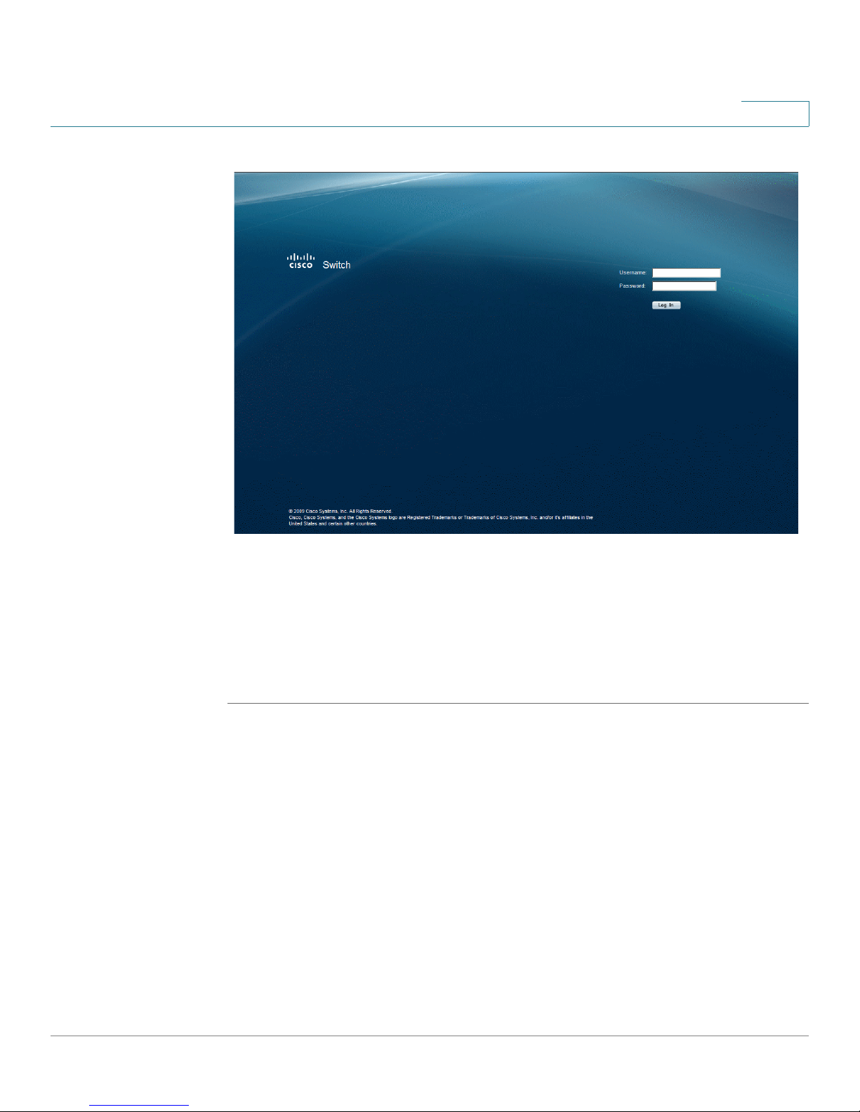
Starting the Application
To open the User Interface:
STEP 1 Open a web browser.
STEP 2 Enter the device’s IP address in the address bar and press Enter. An
Password Page
Enter Network
opens:
Cisco Small Business SFE/SGE Managed Switches Administration Guide 1
Page 11
Getting Started
Starting the Application
1
Enter Network Password Page
STEP 3 When the
Enter a Username and Password and click Log In. The default user name is admin
The default password is admin. Passwords are alpha-numeric and case-sensitive.
While the system is verifying the login attempt, the Login Progress Indicator
appears . The indicator dots rotate clockwise to indicate that the system is still
working.
If the login attempt is successful, the
Enter Network Password Page
System Information Page
initially loads, both fields are empty.
.
opens.
Cisco Small Business SFE/SGE Managed Switches Administration Guide 2
Page 12
Getting Started
Understanding the Interface
1
System Information Page
If the login attempt fails because the user typed an incorrect username or
password, the following message appears: “Invalid Username or Password.
Please try again.”
If the login attempt fails due to another problem one of the following error
messages appears:
“Login failed since too many users are logged in.”
“Login failed due to PC configuration problems.”
“There is no response from the server.”
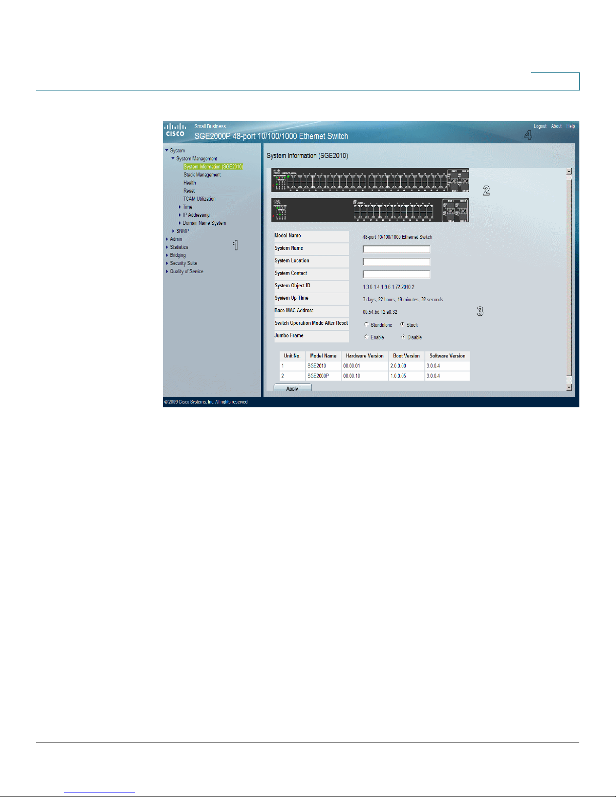
Understanding the Interface
The Interface Components Page displays the interface components with their
corresponding numbers.
Cisco Small Business SFE/SGE Managed Switches Administration Guide 3
Page 13
Getting Started
Understanding the Interface
1
Interface Components Page
The following table lists the interface components with their corresponding
numbers:
Interface Components
Component Description
1 Tree View The Tree View provides easy navigation through the
configurable device features. The main branches expand
to provide the subfeatures.
2 Device View The device view provides information about device ports,
current configuration and status, table information, and
feature components.The device view also displays other
device information and dialog boxes for configuring
parameters.
3 Device Information
Area
The Device Information area displays some basic
information regarding the device and the configuration.
Cisco Small Business SFE/SGE Managed Switches Administration Guide 4
Page 14

Getting Started
Using the Cisco Management Buttons
Using the Cisco Management Buttons
Device Management buttons provide an easy method of configuring device
information, and include the following:
Device Management Buttons
Button Name Description
Apply Applies changes to the device
Clear Counters Clears statistic counters
Clear Logs Clears log files
Add Opens an Add page
Delete Removes entries from tables
Test Performs cable tests
1
Using Screen and Table Options
The User Interface contains screens and tables for configuring devices. This
section contains the following topics:
• Adding Device Information
• Modifying Device Information
• Deleting Device Information
Adding Device Information
User defined information can be added to specific interface pages, by opening a
new Add page. To add information to tables or interface pages:
STEP 1 Open an interface page.
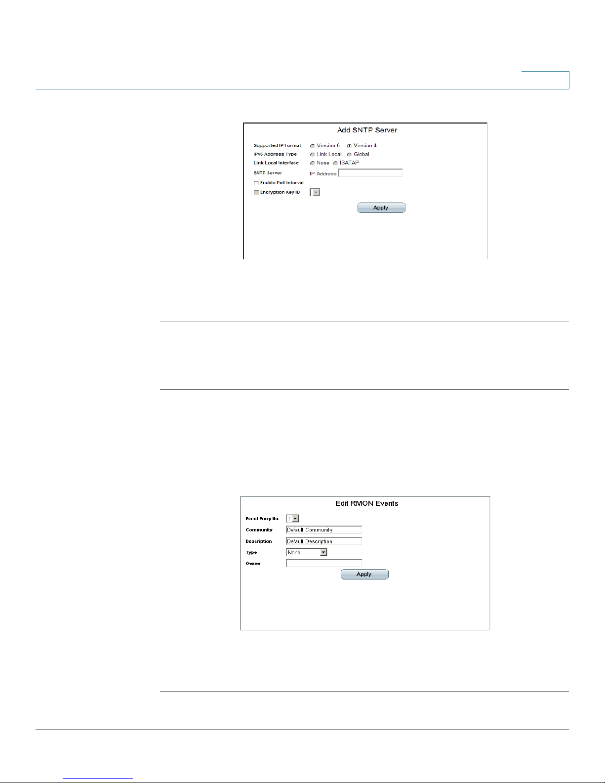
STEP 2 Click the Add button. An add page opens, for example, the
:
Page
Add SNTP Server
Cisco Small Business SFE/SGE Managed Switches Administration Guide 5
Page 15
Getting Started
Using Screen and Table Options
Add SNTP Server Page
STEP 3 Define the fields.
STEP 4 Click Apply. The configuration information is saved, and the device is updated.
1
Modifying Device Information
STEP 1 Open the interface page.
STEP 2 Select a table entry.
STEP 3 Click the Edit Button. A Modify page opens, for example, the
Page
opens:
Edit RMON Events Page
STEP 4 Define the fields.
Edit RMON Events
STEP 5 Click Apply. The fields are modified, and the information is saved to the device.
Cisco Small Business SFE/SGE Managed Switches Administration Guide 6
Page 16

Getting Started
Logging Off of the Device
Deleting Device Information
STEP 1 Open the interface page.
STEP 2 Select a table row.
STEP 3 Check the Remove checkbox.
STEP 4 Click the Delete button. The information is deleted, and the device is updated.
Logging Off of the Device
The application may automatically log out after ten minutes. When this occurs, the
following message is displayed “You have been logged out as a result of being
inactive for 10 minutes. Use the fields to login.” The
opens and, after login, the application returns to the
logout instances, a message is displayed on the
indicate the logged-out state.
1
Enter Network Password Page
System Information Page
Enter Network Password Page
. In all
to
To intentionally log out, click Logout in the top right corner of any screen. The
system logs out and the following message appears: “You have logged out of the
Cisco Unified Managed Switch
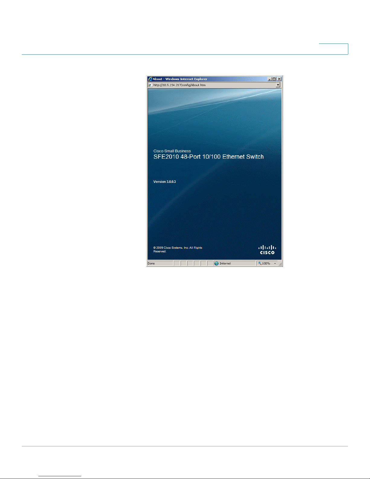
The About Page
Click About in the top right corner of any screen to display
page displays the device name and version number.
The About Page
. This
Cisco Small Business SFE/SGE Managed Switches Administration Guide 7
Page 17
Getting Started
The About Page
1
The About Page
Cisco Small Business SFE/SGE Managed Switches Administration Guide 8
Page 18

Managing Device Information
Defining System Information
Managing Device Information
This section provides information for defining both basic and advanced system
information. This section contains the following topics:
• Defining System Information
• Managing Stacks
• Viewing Device Health
• Resetting the Device
• Defining Bonjour
2
• TCAM Utilization
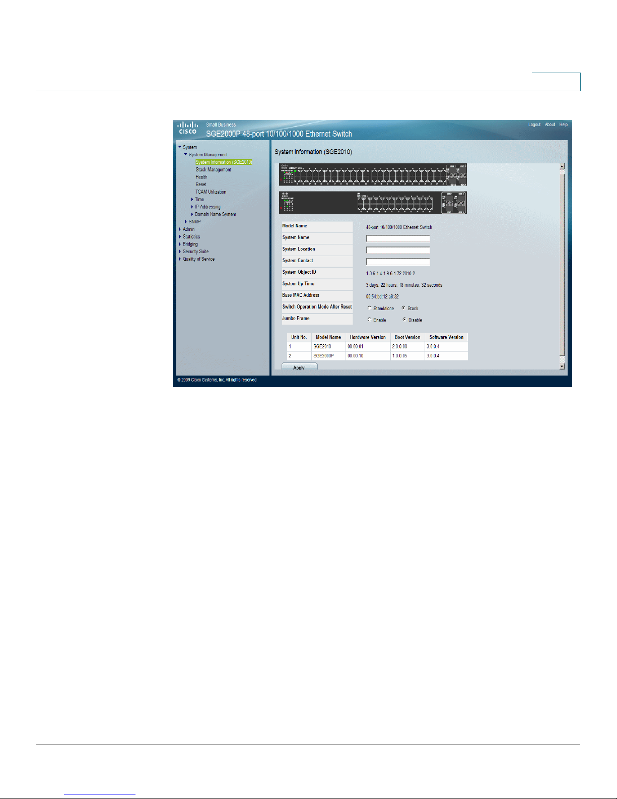
Defining System Information
The
System Information Page
information.
To open the
System Information Page
contains parameters for configuring general device
:
Cisco Small Business SFE/SGE Managed Switches Administration Guide 9
Page 19
Managing Device Information
Defining System Information
2
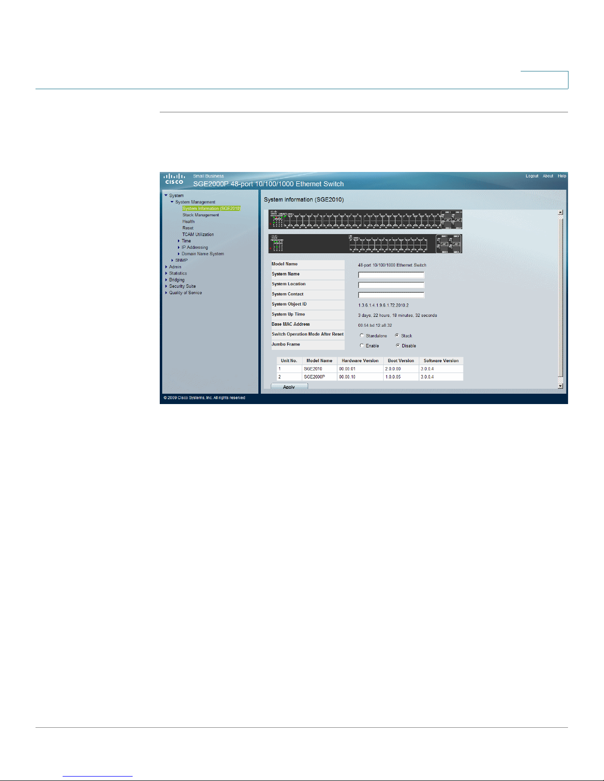
STEP 1 Click System > System Management > System Information. The
Information Page
System Information Page
opens:
System
The
System Information Page
contains the following fields:
• Model Name — Displays the model name and number of ports supported by
the system.
• System Name — Displays the user configured name of the system.
• System Location — Defines the location where the system is currently running.
The field range is up to 0-160 characters.
• System Contact — Defines the name of the contact person. The field range is
up to 0-160 characters.
• System Object ID — Displays the vendor’s authoritative identification of the
network management subsystem contained in the entity.
• System Up Time — Displays the amount of time that has elapsed since the last
device reset. The system time is displayed in the following format: Days, Hours,
Minutes and Seconds. For example: 41 days, 2 hours, 22 minutes and 15
seconds.
• Base MAC Address — Displays the device MAC address. If the system is in
stack mode, the Base MAC Address of the master unit is displayed.
Cisco Small Business SFE/SGE Managed Switches Administration Guide 10
Page 20

Managing Device Information
Managing Stacking
• Hardware Version — Displays the hardware version number.
• Software Version — Displays the software version number. If the system is in
stack mode, the version of the master unit is displayed.
• Boot Version — Indicates the system boot version currently running on the
device. If the system is in stack mode, the version of the master unit is
displayed.
• Switch Operation Mode After Reset — Indicates the mode the device operates
in after the system is reset. The possible field values are:
2
- Standalone — Indicates the device operates as a stand-alone device
after the system is reset.
- Stack — Indicates the device operates as a Stacked unit after the
system is reset.
Managing Stacking
This section contains information for understanding and configuring stacking.
• Configuring a Stack
• Stack Membership
• Defining Stacking Unit ID
• Adding, Replacing and Removing Stacking Members — Examples
• Managing Stacks
Understanding Switch Operating Modes
The device has the following operating modes:
• Stack
• Stand-alone.
Both the Stack and Stand-alone mode can be selected by the user during
software boot or using the device GUI System Information page. The selected
operating mode is enabled after the unit is reset. The factory default is Stack
mode.
Cisco Small Business SFE/SGE Managed Switches Administration Guide 11
Page 21

Managing Device Information
Managing Stacking
Stand-alone Mode
Devices operating in stand-alone mode run as a independent -single unit. All ports
of a stand-alone switch operate as normal Ethernet links. A stand-alone switch
does not participate in a stack even if the device is physically connected to a
stack. However, a unit whose mode is changed from Stack to Stand-alone retains
its stacking configuration information. That information is restored if the unit is
returned to Stack mode.
Stack Mode
Devices operating in stack mode are not an independent unit, but are members of
an organized group of switches known as a stack. A stack consists of a Master, a
Backup Master switch, and up to six stacking member switches.
As a special case, a unit operating in Stacking mode, which is not connected to
any other units, may operate as a stack–of-one.
2
The following device ports of each unit in a stack mode are reserved as stacking
links, and cannot be used for regular network connections.
• SFE2000 - Default stacking ports: G1, G2. Configurable stacking port: G3/GBIC
1, G4/GBIC 2
• SGE2000 - Default stacking ports: 12/GBIC 3, 24/GBIC 4.
• SFE2010 - Default stacking ports: G1, G2. Configurable stacking port: GBIC 1,
GBIC 2.
• SGE2010 - Default stacking ports: 24/GBIC 3, 48/GBIC 4
Configuring a Stack
A stack is initialized by the following sequence of operations:
• Physical connection of the switches in a stack topology. The system
administrator connects the switches to be included in the stack in the
desired order and topology (ring or chain).
• Powering on of the units. The system administrator powers on all the
connected units. (A new stack consisting of factory default units may also
be built by powering the units on one by one, as described in
Recommended Procedures for Building a Stack).
Cisco Small Business SFE/SGE Managed Switches Administration Guide 12
Page 22

Managing Device Information
Managing Stacking
• Master Election. Master Election takes place automatically to select the
• Topology Discovery. The stack Master unit carries out a process called
• Unit ID Conflict Resolution. The Master unit attempts to resolve conflicts
2
Master unit. If there are two or more units in the stack, then a Backup unit is
also automatically selected.
topology discovery to learn which units are present in the stack, the order in
which they are connected and the Unit ID that each unit reports itself as
owning. The Master unit then examines the reported Unit IDs and notes any
violations of the Unit ID Validity Rules. These include units reporting
duplicate Unit IDs and units in factory default (Unit ID=0) mode. Topology
discovery also takes place any time a change in the stack topology occurs,
such as removing or adding a unit to the stack.
among two or more units contending for the same Unit ID. After applying the
rules for Unit ID Conflict Resolution, one unit retains its Unit ID. The other
contending units are either shut down or reset to Unit ID=0 by the Master
unit.
• Automatic Unit ID Assignment. The Master unit applies automatic
numbering to units with Unit ID=0. These units include new factory units,
units reset to factory default mode by the system administrator pressing the
reset button on the switch or units automatically reset to Unit ID=0 by the
Master unit during Unit ID Conflict Resolution.
• Unit and Port Configuration. At this point, the stack has a valid topology. The
Master unit now configures all member units and their ports according to
the configuration file stored in the Master unit. The Stack Initialization is
complete and the stack enters normal operational mode. Configuration files
are changed only through explicit user configuration. Configuration files are
not automatically modified when:
- Units are Added
- Units are Removed
- Units are reassigned Unit IDs
- Units toggle between Stacking Mode and stand-alone Mode
Each time the system reboots, the Startup Configuration file in the Master
unit is used to configure the stack. If a stack member is removed from the
stack, and then replaced with a unit with the same Unit ID, the stack
member is configured with the original device configuration. Only ports that
are physically present are displayed in the web screens, and can be
Cisco Small Business SFE/SGE Managed Switches Administration Guide 13
Page 23

Managing Device Information
Managing Stacking
Stack Membership
The system supports up to eight switching units per stack. A stack is comprised of
three stacking member types:
• Stacking Master — Provides a single control, configuration and management
point for stacking members through a single IP address interface. The Stacking
Master maintains the stack management, device configuration. In addition, the
Stacking Master detects and reconfigures the ports with minimal operational
impact in the event of unit failure, inter-unit link failure, and unit insertion or
removal. A stack must contain a single Stacking Master.
2
configured through the web management system. By default, Unit IDs are
assigned automatically. However, you can use the browser to assign a
specific Unit ID; for example, the same unit ID as the unit which was recently
removed.
Each port in the stack has a specific Unit ID, port type, and port number, which
is part of both the configuration commands and the configuration files.
Configuration files are managed only from the Master unit. This includes:
• Saving to the FLASH
• Uploading Configuration files to an external TFTP Server
• Downloading Configuration files from an external TFTP Server
• The Backup Master is a stacking member that receives a copy of the Stacking
Master Configuration file. A stack can contain a single Backup unit or none at all.
The Backup unit replaces the Master unit if one of the following events occur:
• The Master unit fails or is removed from the stack.
• Links from the Master unit to the stacking units fail.
• A soft switchover is performed via the web interface.
Switching between the Stacking Master and the Backup Master results in a
limited service loss. The Stacking Master and the Backup Master maintain a
Warm Standby, meaning that the Stacking Master and the Backup units are
synchronized with the static configuration only. Any Dynamic Address Tables
are relearned if a failure occurs. The Running Configuration file is synchronized
between the Stacking Master and the Backup, and continues running on the
Backup Master.
Cisco Small Business SFE/SGE Managed Switches Administration Guide 14
Page 24

Managing Device Information
Managing Stacking
• The stacking members operate under the control of the Master unit. Device
software is downloaded separately for each stack member. All stacking
members must run the same software version. A stack may contain from zero
to six stacking members (not including the Backup unit).
Defining Stacking Unit ID
Each member unit of a stack is assigned a Unit ID. The Unit ID assignment can be
manually selected by the system administrator or automatically selected by the
software. The value of the Unit ID also signifies the class of unit. For a stack
comprised of factory default units only, the Unit IDs are assigned as follows:
• Unit ID 1 - Stacking Master
• Unit ID 2 - Backup Master
2
• Units ID 3 - 8 - Stacking members.
The Unit ID is displayed by a LED indicator on the front panel.
Units of a stack do not have to be connected in sequential order. For example, a
stack may consist of the units connected in the following order:
Unit 3—Unit 5—Unit 1—Unit 4—Unit 2
It is recommended that a stack of new, factory default switches be initially
configured in the automatic mode. This ensures that a group of factory delivered
switches can be easily configured as a stack. After the initial setup of the stack,
the Unit ID mode for a stack member may be changed.
Master-enabled Units and Force Master
Unit 1 and Unit 2 are called Master-Enabled units because they are the only units in
an existing stack that are eligible to become the Master unit. One of these units
becomes the Master unit and the other becomes the Backup unit. The Master unit
selection can be made automatically by the system, or manually by the system
administrator by setting one of the Master-enabled units as Force Master. The
Backup unit may also be selected automatically by the system, or manually by
setting the Unit ID. For example, the system administrator may set Unit 2 as Force
Master and manually number another unit to be Unit 1. In this case Unit 2 becomes
the Master unit and Unit 1 becomes the Backup unit.
Stacking Member Unit IDs
Units 3 through 8 are assigned to stacking members. Stacking members are
managed by the Master unit.
Cisco Small Business SFE/SGE Managed Switches Administration Guide 15
Page 25

Managing Device Information
Managing Stacking
Factory Default Units
A unit in factory default mode has the following attributes:
• Unit ID = 0. This setting indicates that the unit is in autonumbering mode.
• Switch Operation Mode = Stack.
The combination of these two settings directs the system to automatically
configure the unit as a new stack member.
NOTE: A unit in stand-alone mode also displays Unit ID = 0.
Unit ID Validity Rules
Each member unit of a stack has a Unit ID that satisfies two conditions:
• A Unit ID is a number from 1 to 8.
2
• A Unit ID is unique within the stack.
Automatic Unit ID Assignment
Automatic Unit ID assignment is applied to Stack mode units with Unit ID of 0. This
includes factory default units as well as units whose Unit IDs are reset to 0 as a
result of Unit ID Conflict Resolution.
The Automatic Unit ID Assignment for units with Unit ID=0 proceeds as follows:
• A Unit ID is assigned from the available valid, unique Unit IDs, starting with the
lowest available Unit ID.
• If two or more units are queued to receive Unit IDs, the units are assigned Unit
IDs starting with the unit with the lowest MAC address.
Manual Unit ID Assignment
The system administrator can assign a specific, valid Unit ID to a stack member
manually. A Unit ID that is manually assigned is not subject to automatic numbering.
Manual numbering for stacking members is beneficial for providing a fast and easy
way of replacing stacking members. After a stack is initialized in factory default,
automatic numbering mode, the Unit IDs can be manually set to the same Unit IDs
assigned by automatic numbering. The system administrator can then configure
the switch ports. The port configuration of the switch is automatically stored in the
Stacking Master and Backup Master. If a stacking member must be replaced, an
identical replacement stacking member can be hot swapped into the running
stack. The hot swap can occur if the new stacking member is manually in the same
Cisco Small Business SFE/SGE Managed Switches Administration Guide 16
Page 26

Managing Device Information
Managing Stacking
Unit ID as the switch being replaced. The newly inserted switch is identified by the
Master unit by its Unit ID. Since the configuration of the original switch is also
stored in the Master and Backup units by Unit ID, the new switch automatically
receives the configuration of the old switch. This eliminates the need to configure
the new switch and reduces the system downtime.
The advantage of manual vs. automatic unit numbering is illustrated in the
following example:
A stack consists of Units 1,2,4,6,7. Unit 7 fails and an identical replacement unit is
inserted. If the replacement unit is manually pre-set to be Unit 7, it can be inserted
into the stack and inherit the configuration of the replaced (failing) Unit 7. However,
if the replacement unit is not preset but is inserted in factory default mode (Unit 0),
it is automatically renumbered to Unit 3 because that is the lowest available Unit ID
in the stack. The new Unit 3 now inherits the previous unit 3 configuration.
Otherwise, the system administrator must manually configure all the ports of the
new Unit 3.
2
Unit ID Conflict Resolution
If two or more stacking members have the same valid Unit ID, the Master attempts
to resolve the conflict by awarding the contested Unit ID to one of the units. For
stacking members that are not granted the unit ID, the Stacking Master either:
• Automatically resets the Unit ID to 0. The Stacking members become eligible to
be reassigned another Unit ID by Automatic Unit ID Assignment.
• The units are shut down. A unit that is automatically shut down remains
powered on, but it is not operational, indicated by the solid red port Led. It is
not a member of the stack and its connections are effectively disconnected
from its immediate neighbors in the stack. If the stack is initially connected in a
ring topology, the shutdown unit changes the topology into a chain. However, if
the stack is initially configured in a chain topology, the shutdown unit breaks the
chain. Depending on the particular configuration, may lead to other units being
shut down. An automatically shut down unit remains shut down until the system
administrator, manually renumbers the stacking member or removes the
stacking member from the stack. A message is sent to the user that a unit failed
to join the stack.
The Master unit attempts to resolve Unit ID conflicts by applying the following
rules:
Cisco Small Business SFE/SGE Managed Switches Administration Guide 17
Page 27

Managing Device Information
Managing Stacking
STEP 1 When inserting a unit into a running stack, units that are members of the existing
stack retain their Unit IDs. Therefore:
• If an automatically numbered unit was inserted into a running stack, the
• If a manually numbered unit was inserted into a running stack, the existing
STEP 2 When adding a unit to a stack at stack reset (boot), units with duplicate Unit IDs
contend with each other for the same Unit ID according to the rules and
restrictions imposed upon their unit class.
• Master-enabled units with duplicate Unit IDs compete with each other in the
2
existing unit retains its Unit ID and the newer unit is reset to Unit ID=0.
unit retains its Unit ID and the manually numbered unit is shut down because
its Unit ID cannot be changed automatically.
Master Election.
• If two units are contending for the same Unit ID, the Master decides as
follows:
- If one unit is manually numbered and the other unit is automatically
numbered, the manually numbered unit retains its Unit ID and the
automatically numbered unit is reset to Unit ID=0.
- If both units are automatically numbered, the unit with the lower MAC
address retains its Unit ID and the other unit is reset to Unit ID=0.
- If both units are manually numbered, the unit with the lower MAC
address retains its Unit ID and the other unit is shut down.
STEP 3 Two manually numbered units with the same Unit ID can never be added or
inserted into a stack simultaneously. Both units are shut down.
STEP 4 When inserting new units into a running stack, if the resulting total number of old
and new units exceeds the maximum allowed (eight), all the new units are shut
down.
STEP 5 Connecting more than the maximum number (eight) of units in a new stack may
produce unpredictable results due to race conditions among the units.
STEP 6 Any units that have been reset to Unit ID 0 are then reassigned new Unit IDs, if
possible, by Automatic Unit ID Assignment.
Cisco Small Business SFE/SGE Managed Switches Administration Guide 18
Page 28

Managing Device Information
Managing Stacking
Master Election
The Master and Backup unit selection is known as Master Election. Master Election
takes place if there are one or more eligible candidates contending to be the
Master unit.
Master Election Candidate Eligibility
In general, not all stack member units are eligible to be candidates for Master
Election. Eligibility for Master Election is determined in the following order.
STEP 1 All Master-enabled switching units present in a stack are candidates for Master
Election. All units that are not Master-enabled are not eligible for Master Election.
STEP 2 If there are no Master-enabled units present in a stack, then all units in factory
default mode (Unit ID=0, Switch Operation Mode=Stack) are candidates for Master
Election. No other units are eligible for Master Election.
2
If neither Master-enabled nor factory default units are present, Master election
does not take place and all units in the stack are effectively shut down. The stack
remains in this inoperable state until either a new Master-enabled unit is
connected to the stack or a current stack unit is manually reset to factory default
mode (by pressing the reset switch on the front panel of the switch and holding it
down for at least ten seconds).
Master Election Selection Rules
If there are two or more candidates for Master Election, the Stack Master is
determined by comparing attributes of the contending units in a specific order.
The order in which the attribute comparisons are made is:
• 1 - Unit assigned by the system administrator as Force Master
• 2 - Unit with the longest running time (measured in 10 minute increments)
• 3 - Unit having Unit ID=1
• 4 - Unit having the lowest MAC address
The Master Election proceeds by making the attribute comparisons in the above
specified order. If there is a tie at any step, the election proceeds to the next step.
However, units that fail to tie at any step are eliminated from the competition. Units
that succeed in the tie in a given step, go on to compete in the next step. The
election is decided at the first step for which there is a clear winner. The winner of
that step is the winner of the Master Election and becomes the Master unit.
Cisco Small Business SFE/SGE Managed Switches Administration Guide 19
Page 29

Managing Device Information
Managing Stacking
For example:
• If there are two or more Master-enabled units and only one of them has
• If there are two or more Master-enabled units that have been assigned as
• If there is no winner of step 2, the election proceeds to step 3. Only
2
been assigned as Force Master, the Force Master unit is the winner of step 1
and therefore the winner of the Master Election.
Force Master, then the Master Election proceeds to step 2, where the
running times of the Force Master units are compared. If there is a winner at
step 2, then the winner of that step also wins the Master Election and
becomes the Master unit.
contending units that have succeeded in tieing in previous steps remain
contenders. If there is a single unit with Unit ID=1, then that unit wins step 3
and the Master Election.
• If there are two or more units assigned to Unit ID=1, then the election
proceeds to step 4. There is always a winner of step 4 because MAC
addresses are unique.
Master Election Backup Unit Selection Rules
The candidate that wins the Master Election becomes the Master unit. If there is a
single runner-up unit, that unit becomes the Backup unit. If there is a tie for the
runner-up position, then the tie is resolved by applying the Unit ID Conflict
Resolution rules.
Recommended Procedures for Building a Stack
To avoid possible Unit ID conflicts and device shutdowns, Cisco recommends that
the following procedures be adopted when configuring and managing stacks:
• A stack should be initially configured by connecting all stack members in
factory default mode.
• If there is a preference for assigning specific Unit IDs to specific devices, then
the stack should be built by connecting and booting the devices, in factory
default mode, one by one in the desired Unit ID order that they will be assigned
in the stack. That is, the device that will be the Master unit should be powered
on first. After it boots and is automatically numbered (as Unit 1) it becomes the
Master unit. The unit that will become the Backup unit is then connected to the
Master unit and powered on. It is assigned to be Unit 2 by the Master unit and
becomes the Backup unit. The next unit is then connected to either the Master
(Unit 1) or Backup (Unit 2) unit and then powered on. It is assigned to be Unit 3
by the Master unit. Subsequent units are joined to the stack by connecting
Cisco Small Business SFE/SGE Managed Switches Administration Guide 20
Page 30

Managing Device Information
Managing Stacking
each one to any existing stack member unit and then powering the new unit on.
Each new unit is assigned the next available Unit ID.
• After the stack is initialized and configured, the system administrator may reset
the Unit IDs manually to the same values assigned by automatic numbering.
Adding, Replacing and Removing Stacking Members —
Examples
The following examples illustrate stacking behavior when adding, replacing or
removing stack members:
• A stack is initially configured with Units 1,2,3,4,5,6,7,8. Master Unit 1 is then
removed while the stack is running and is replaced with another switch that is
in factory default mode. What happens?
2
When Master Unit 1 is removed, Backup Unit 2 automatically becomes the
Master unit. The newly inserted Unit 0 enters the stack and is automatically
numbered as Unit 1, but remains a stacking member (Since it did not enter the
stack as a Master-enabled unit and the stack already had a Master unit, its
entry did not trigger a Master Election.). However, after being assigned to be
Unit 1, it becomes a Master-enabled unit and will be a candidate in the next
Master Election. For instance, if the stack is reset, it will win the Master Election
and become the Master unit, while the present Master unit, Unit 2, will become
the Backup unit.
Removing or replacing stack members incorrectly may result in an inoperable unit
or stack, as illustrated in the following examples:
• A stack is initially configured with Units 1,2,4,6,7. Units 1 and 2 are then
removed, leaving Units 4, 6, 7. The stack is permanently disabled because
there is no Master unit, and the remaining units 4, 6, 7 are shut down. There
are no Master-enabled units, so Master Election cannot take place. In this
example, it makes no difference whether or not Units 4, 6, 7 were
automatically numbered or manually numbered. Rebooting the units does
not change the situation, even for automatically numbered units. Since there
are no Unit ID conflicts, all the units retain their Unit IDs and therefore
Automatic Unit ID Assignment does not occur. Then, after rebooting, all units
are again shut down. Only by selecting one of the remaining units to be
Force Master or by manually resetting at least one of them to factory default
(Unit 0) mode can these units be configured as an active stack.
Cisco Small Business SFE/SGE Managed Switches Administration Guide 21
Page 31

Managing Device Information
Managing Stacking
• A stack is initially configured in chain topology and the units are connected
• In the previous example, suppose that the system administrator realizes the
2
as follows:
Unit 2—Unit 5—Unit 1—Unit 4—Unit 6—Unit 8
The system administrator resets Unit 4 but does not realize that the Switch
Operation Mode After Reset field on the
mistakenly checked as
Unit 4 reboots in stand-alone mode, effectively cutting off Units 6 and 8
from the stack. Units 6 and 8 are shut down. The stack continues to operate,
but with Units 1, 2 and 5 being the only active units.
error after rebooting Unit 4 as a stand-alone device. The system
administrator should reboot Unit 4 in Stack mode. If the stack has not been
reset, the Master unit retains the original stack configuration file. Also, Unit 4
retains its stacking configuration information when its mode is changed
from Stack to stand-alone, and restores that information when returning to
Stack mode.
stand-alone
System Information
. No physical connections are changed.
page was
• A stack is initially configured and all units are manually numbered. The units
are connected in a chain topology as follows:
Unit 2—Unit 5—Unit 1—Unit 3—Unit 4—Unit 6—Unit 7—Unit 8
Unit 3 fails. Since Units 4, 6, 7 and 8 are cut off from the Master unit, they are
automatically shut down. This leaves only Units 1, 2 and 5 running in the
stack.
The system administrator prepares a replacement unit by manually
renumbering a unit from another stack. However, the replacement unit is
mistakenly renumbered as Unit 4 instead of Unit 3. What happens if the
replacement unit is inserted into the running stack (in the same position as
Unit 3)? When the new Unit 4 is inserted into the running stack, the Master
unit executes Topology Discovery and discovers the new Unit 4. But now
the presence of the old Unit 4 is also discovered because of the revived
Cisco Small Business SFE/SGE Managed Switches Administration Guide 22
Page 32

Managing Device Information
Managing Stacks
• A stack is initially configured in a chain topology as follows:
2
connection to the stack via the new Unit 4. The old Unit 4 and the new Unit 4
appear to the Master unit as two new, manually numbered units trying to
simultaneously join the stack. Therefore, both units are shut down, and thus
Units 6, 7 and 8 remain shut down.
What happens if the replacement unit is inserted into the stack (in the same
position as Unit 3) after first powering off all units and then simultaneously
powering on all units?
If all units in the stack are reset, the Master unit performs Topology
Discovery during the software boot, revealing that there are two duplicate
Unit IDs (old and new Unit 4). Since both units are manually numbered, both
units are shut down by the Master unit. This, in turn, again leaves Units 6, 7
and 8 disconnected from the Master unit, thus shutting them down also.
Managing Stacks
The
members on the device and determine to either reset the entire stack or a specific
device. Device configuration changes that are not saved before the device is reset
are not saved. If the Master unit is reset, the entire stack is reset.
Unit 8—Unit 5—Unit 1—Unit 3—Unit 4—Unit 6—Unit 7—Unit 2
Unit 1 is the Master and Unit 2 is the Backup. Unit 3 fails. What happens?
The failure of Unit 3 disconnects Units 4, 6, 7 and 2 from the Master unit.
Backup Unit 2 senses the loss of the Master and automatically becomes the
Master of a stack comprised of Units 2, 4, 6 and 7. Unit 1 remains the Master
of the now reduced stack, consisting of Units 1, 5 and 8. Thus the failure of
Unit 3 has split the original stack into two smaller stacks. However, while the
two stacks continue in operation, this situation may create problems on the
network because Unit 2 and Unit 1 have the same Master configuration files.
The significance of this is that both stacks share the same IP address,
making network communication with either stack ambiguous.
Stack Management Page
allows network managers to configure stacking
To open the
Cisco Small Business SFE/SGE Managed Switches Administration Guide 23
Stack Management Page
:
Page 33

Managing Device Information
Managing Stacks
2
STEP 1 Click System > System Management > Stack Management. The
opens:
Stack Management Page
Stack Management Page
The
Stack Management Page
• Master Election — Indicates the method of electing the master device. The
possible values are:
-
Automatically
-
Force Maste
only Unit 1 or Unit 2 can be the stack master.
— The master is selected automatically by software.
r — The unit is forced to be master of the stack. Note that
• Unit No. — Displays the stacking member unit number for which the stacking
parameters are displayed.
• Model Name — Displays the model name of ports supported by the system.
• Unit No. After Reset — Indicates the new unit number of the stacking member
after the device is reset.
• Uplink — Indicates the next higher stacking unit in the uplink path.
• Downlink — Indicates the next lower stacking unit in the downlink path.
STEP 2 Define the relevant fields.
contains the following fields:
Cisco Small Business SFE/SGE Managed Switches Administration Guide 24
Page 34

Managing Device Information
Viewing Device Health
STEP 3 Click Apply. Stack management is defined, and the device is updated.
Viewing Device Health
The
Health Page
the device’s power and ventilation sources.
2
displays physical device information, including information about
STEP 1 Click System > System Management > Health. The
Health Page
Health Page
opens:
The
Health Page
• Unit No. — Indicates the number of stack member for which the device
information is displayed.
• Power Supply Status — Displays the power supply status. The internal power
supply is displayed as PS in the interface, while the redundant power supply is
displayed as RPS. If the status is displayed as
redundant power supply is not connected (for RPS only).
• Fan Status — Displays the fan status. The device has up to five fans. Each fan is
denoted as fan plus the fan number. The possible field values are:
Cisco Small Business SFE/SGE Managed Switches Administration Guide 25
contains the following fields:
Not Present,
this indicates that a
Page 35

Managing Device Information
Resetting the Device
-
OK —
-
Fail —
NOTE: The GE device has up to five fans (the FE device has one fan).
Resetting the Device
The
Reset Page
changes to the Start up Configuration file before resetting the device. This
prevents the current device configuration from being lost.
If a Master unit and/or a backup Master unit is removed from the stack and the user
wishes to configure one of the member units (Units 3-8) to be a backup Master, the
user must reset the unit and configure a new unit number to stack (using the Unit
number selection process).
2
Indicates the fan is operating normally.
Indicates the fan is not operating normally.
enables the device to be reset from a remote location. Save all
The following resets the device:
• Restart / Reboot — Resets the device. Ensure the device configuration has
been saved.
• Restore Default — The device is restored to the factory default
configuration. In Stacking mode, unit no. 1 becomes the Master, and the
stacking members are reset.
To open the
Reset Page
:
Cisco Small Business SFE/SGE Managed Switches Administration Guide 26
Page 36

Managing Device Information
Defining Bonjour
2
STEP 1 Click System > System Management > Reset. The
Reset Page
Reset Page
opens:
STEP 2 Click one of the available Reset commands. The device resets.
STEP 3 Enter the user name and password to reconnect to the Web Interface.
Defining Bonjour
Bonjour is a service discovery protocol that enables automatic discovery of
computers, devices and services on IP networks. Bonjour’s
Name System
sending and receiving UDP packets only to the following multicast address
224.0.0.251 and to port number 5353.
The
device, specifying a Service Type and the related port used for publishing
devices over the network. A Service Type is the type of service registration
performed as part of the device system start up. It is intended to assure the
uniqueness of the published service and proclaims the related information. The
device information published via DNS includes the following details:
(mDNS) service allows the device to publish device services by
Bonjour Page
multicast Domain
contains information for enabling/disabling Bonjour on the
Cisco Small Business SFE/SGE Managed Switches Administration Guide 27
Page 37

Managing Device Information
Defining Bonjour
• Model Number
• Device Type
• Firmware Version
• MAC Address
• Serial Number
• Hostname
The Service Types that are provided for Bonjour are: _csbdp, (a Cisco specific
Service Type) , HTTP, HTTPS and Other. Other allows for additional Service Types
to be added manually.
To define Bonjour:
2
STEP 1 Click System > Admin > Bonjour. The
Bonjour Page
Bonjour Page
The
contains the following fields:
Bonjour Page
opens:
• Bonjour State — Enables Bonjour thereby allowing the Switch to publish
device services via Bonjour using the mDNS service. The possible field values
are:
-
Cisco Small Business SFE/SGE Managed Switches Administration Guide 28
Enable
— Enables Bonjour on the device. This is the default value.
Page 38

Managing Device Information
Defining Bonjour
-
Disable
2
— Disables Bonjour on the device.
• Service Type Selection — Defines the
Service Type used to publish devices on the network. The possible field
values are:
-
_csbdp (default)
is a Cisco generic Service Type. The port number is chosen randomly
from the port range of 4000-5000 at the initialization stage and is used
afterwards. This is the default value.
-
HTTP
published using the default http TCP port 80. HTTP is used mainly for
human-readable HTML content served over HTTP.
-
HTTPS
is published using the default http TCP port 443.
-
Other
— Specifies the Service Type selected is HTTPS which is
— Specifies the Service Type selected is secured HTTP which
— Indicates a user-defined Service Type to be added.
— Specifies the Service Type selected is _csbdp. This
DNS Service Discovery
(DNS-SD)
• Service Type — Displays the selected Service Type defined in the Service
Typ e f ie ld.
• Port — Defines the selected port used for the relevant Service Type. The port
number for _csbdp, HTTP and HTTPS Service Types are predefined and
therefore are displayed as read-only values.
STEP 2 Select a Service Type from the Service Type Selection drop-down field.
STEP 3 Define a Port number, only if Other is the selected Service Type.
STEP 4 Click Apply. The Service Type is defined, and the device is updated.
Disabling Bonjour
STEP 1 Click System > Admin > Bonjour. The
STEP 2 Select Disable from the Bonjour State field drop-down menu.
STEP 3 Click APPLY. The Bonjour protocol is disabled, and the device is updated.
Bonjour Page
opens:
Cisco Small Business SFE/SGE Managed Switches Administration Guide 29
Page 39

Managing Device Information
TCAM Utilization
TCAM Utilization
The maximum number of rules that may be allocated by all applications on the
device is 1024. Some applications allocate rules upon their initiation. Additionally,
applications that initialize during system boot use some of their rules during the
startup process.
The following table lists all applications that can allocate TCAM rules. Each
allocation has its specific allocation policy.
2
Cisco Small Business SFE/SGE Managed Switches Administration Guide 30
Page 40

Managing Device Information
TCAM Utilization
TCAM Allocation
2
Application Per
QoS
Advanced
Mode rules
Access
Control
Rules
PVE Port 2/port or
IP Subnet
VLAN
Protocol
Based VLAN
MAC Based
VLAN
DHCP
Snooping
IP Source
Guard
Port/
Per
Device
Port 6/device No limit 1 or 2 TCAM entries per each rule. Feature is activated
Port 6/device No limit 1 or 2 TCAM entries per each rule. Feature is activated
Port 0 255 2 or 4 Rules are duplicated
Port 0 No limit 1 or 2 Rules are duplicated
Port 0 432 1 or 2 Rules are duplicated
Device 2/device No limit 8 TCAM entries/1 DHCP Snooping rule
Port 0 No limit 1 TCAM entry/1 IP Source Guard entry
Allocation
on
Activation
LAG
Application
Upper Limit
--- --- Feature is activated
TCAM rules per User ACL Comments
by default.
by default.
by default.
Allocation done only
during initialization.
for both IP and MAC
based VLANs.
for both IP and MAC
based VLANs.
for both IP and MAC
based VLANs.
ARP
Inspection
VLAN Rate
Limiting
Device 2/device 128 4 TCAM entries/1 ARP Inspection rule
Both 0 255 1 global rule/1 VLAN Rate Limit.
Additional rule is created for each
“permit” rule on the interface.
Cisco Small Business SFE/SGE Managed Switches Administration Guide 31
Page 41

Managing Device Information
TCAM Utilization
TCAM Utilization Page
2
The
TCAM Utilization Page
• TCAM Utilization
which are used. For example, if more ACLs and policy maps are defined, the
system uses more TCAM resources.
—
contains the following fields:
Indicates the percentage of the available TCAM resources
Cisco Small Business SFE/SGE Managed Switches Administration Guide 32
Page 42

Configuring System Time
Defining System Time
Configuring System Time
The device supports the Simple Network Time Protocol (SNTP). SNTP assures
accurate network device clock time synchronization up to the millisecond. Time
synchronization is performed by a network SNTP server. The device operates
only as an SNTP client, and cannot provide time services to other systems.
This section provides information for configuring the system time, and includes the
following topics:
• Defining System Time
• Defining SNTP Settings
3
• Defining SNTP Authentication
Defining System Time
The
System Time Page
both the local hardware clock, and the external SNTP clock. If the system time is
kept using an external SNTP clock, and the external SNTP clock fails, the system
time reverts to the local hardware clock. Daylight Savings Time can be enabled on
the device.
To define system time:
contains fields for defining system time parameters for
Cisco Small Business SFE/SGE Managed Switches Administration Guide 33
Page 43

Configuring System Time
Defining System Time
3
STEP 1 Click System > System Management > Time > System Time. The
Page
opens:
System Time Page
The
System Time Page
contains the following fields:
• Clock Source — Indicates the source used to set the system clock. The
possible field values:
System Time
-
Use Local Settings —
the default value.
-
Use SNTP Server —
The system time is set on the local device. This is
Sets the system time via an SNTP server.
• Date — Indicates the system date. The field format is , for example, .
• Local Time — Indicates the system time. The field format is HH:MM:SS, for
example, 21:15:03.
• Time Zone Offset — Indicates the difference between
(GMT) and local time. For example, the Time Zone Offset for Paris is GMT +1,
while the local time in New York is GMT –5. There are two types of daylight
settings, either by a specific date in a particular year or a recurring setting
irrespective of the year. For a specific setting in a particular year complete the
Daylight Savings
area, and for a recurring setting, complete the
Greenwich Mean Time
Recurring
area.
• Daylight Savings — Enables the Daylight Savings Time (DST) on the device
based on the devices location. The possible field values are:
-
USA —
Cisco Small Business SFE/SGE Managed Switches Administration Guide 34
Page 44

Configuring System Time
Defining System Time
• Time S et Of fset — Indicates the difference in minutes between DST and the
The following fields are active for non-USA and European countries.
-
European —
in March and reverts to standard time at 1:00 am on the last Sunday in
October. The
European countries using the EU standard.
-
Other —
locality. If Other is selected, the
local standard time. The default time is 60 minutes.
The device switches to DST at 1:00 am on the last Sunday
European
The DST definitions are user-defined based on the device
option applies to EU members, and other
From
and
To
fields must be defined.
- From — Indicates the time that DST ends in countries other than USA or
Europe in the format in one field and time in another. For example, DST
begins on the 25th October 2007 5:00 am, the two fields will be
25Oct07 and 5:00.
3
- To — Indicates the time that DST ends in countries other than USA or
Europe in the format in one field and time in another. For example, DST
ends on the 23rd March 2008 12:00 am, the two fields will be 23Mar08
and 12:00.
• Recurring — Select if the DST period in countries other than USA or European
is constant from year to year. The possible field values are:
• From — Indicates the day and time that DST begins each year. For example,
DST begins locally every second Sunday in April at 5:00 am. The possible field
values are:
-
Day —
possible field range is Sunday- Saturday.
-
Week —
The possible field range is 1-5.
-
Month —
possible field range is Jan.-Dec.
-
Time —
Hour:Minute, for example, 02:10.
The day of the week from which DST begins every year. The
The week within the month from which DST begins every year.
The month of the year in which DST begins every year. The
The time at which DST begins every year. The field format is
• To — Indicates the day and time that DST ends each year. For example, DST
ends locally every fourth Friday in October at 5:00 am. The possible field
values are:
-
Cisco Small Business SFE/SGE Managed Switches Administration Guide 35
Day —
field range is Sunday-Saturday.
The day of the week at which DST ends every year. The possible
Page 45

Configuring System Time
Defining SNTP Settings
-
Week —
possible field range is 1-5.
-
Month —
possible field range is Jan.-Dec.
-
Time —
Hour:Minute, for example, 05:30.
STEP 2 Define the relevant fields.
STEP 3 Click Apply. The Time Settings are defined, and the device is updated.
Defining SNTP Settings
3
The week within the month at which DST ends every year. The
The month of the year in which DST ends every year. The
The time at which DST ends every year. The field format is
The
SNTP Settings Page
as adding new SNTP servers. In addition, the
device to request and accept SNTP traffic from a server.
To define SNTP global settings:
contains information for enabling SNTP servers, as well
SNTP Settings Page
enables the
Cisco Small Business SFE/SGE Managed Switches Administration Guide 36
Page 46

Configuring System Time
Defining SNTP Settings
3
STEP 1 Click System > System Management > Tim e > SNTP Settings. The
Page
opens:
SNTP Settings Page
SNTP Settings
The
SNTP Settings Page
contains the following fields:
• Enable SNTP Broadcast — Enables polling the selected SNTP Server for
system time information.
• SNTP Server — Indicates the SNTP server IP address. Up to eight SNTP
servers can be defined.
• Poll Interval — Defines the interval (in seconds) at which the SNTP server is
polled for system time information. By default, the poll interval is 1024 seconds.
• Encryption Key ID — Indicates the Key Identification used to communicate
between the SNTP server and device. The range is 1 - 4294967295.
• Preference — The SNTP server providing SNTP system time information. The
possible field values are:
-
Primary
-
Secondary
-
In progress
information.
— The primary server provides SNTP information.
— The backup server provides SNTP information.
— The SNTP server is currently sending or receiving SNTP
Cisco Small Business SFE/SGE Managed Switches Administration Guide 37
Page 47

Configuring System Time
Defining SNTP Settings
• Status — The operating SNTP server status. The possible field values are:
• Last Response — Indicates the last time a response was received from the
-
Unknown
is unknown. For example, the device is currently trying to locate an
interface.
-
Up
— The SNTP server is currently operating normally.
-
Down
example, the SNTP server is currently not connected or is currently
down.
-
Unknown
sntp server.
SNTP server.
3
— The progress of the SNTP information currently being sent
— Indicates that a SNTP server is currently not available. For
— Indicates that the device (sntp client) is currently looking for
• Offset — Indicates the difference in minutes between DST and the local
standard time.The default time is 60 minutes.
• Delay — Indicates the amount of time it takes to reach the SNTP server.
STEP 2 Click the Add button. The
Add SNTP Server Page
The
Add SNTP Server Page
• Supported IP Format — Provides the supported IP format: Version 6 or
Version 4.
Add SNTP Server Page
contains the following fields:
opens:
- IPv6 Address Type — Indicates the type of IP Address: Link Local or
• SNTP Server — The SNTP server’s IP address.
• Enable Poll Interval — Select whether or not the device polls the selected
SNTP server for system time information.
Cisco Small Business SFE/SGE Managed Switches Administration Guide 38
Global.
Page 48

Configuring System Time
Defining SNTP Authentication
• Encryption Key ID — Select if Key Identification is used to communicate
between the SNTP server and device. The range is 1 - 4294967295.
STEP 3 Define the relevant fields.
STEP 4 Click Add. The SNTP Server is added, and the device is updated.
Defining SNTP Authentication
The
SNTP Authentication Page
of the SNTP server.
3
provides parameters for performing authentication
STEP 1 Click System > System Management > Time > SNTP Authentication. The
Authentication Page
SNTP Authentication Page
opens:
SNTP
The
SNTP Authentication Page
• Enable SNTP Authentication — Indicates if authenticating an SNTP session
between the device and an SNTP server is enabled on the device. The
possible field values are:
Cisco Small Business SFE/SGE Managed Switches Administration Guide 39
contains the following fields:
Page 49

Configuring System Time
Defining SNTP Authentication
• Encryption Key ID — Indicates the Key Identification used to authenticate the
• Authentication Key — Displays the key used for authentication.
• Tru ste d K ey — Indicates the encryption key used (Unicast/Anycast) or elected
3
-
Checked
SNTP server.
-
Unchecked
device and SNTP server.
SNTP server and device. The field value is up to 4294967295 characters.
(Broadcast) to authenticate the SNTP server.
— Authenticates SNTP sessions between the device and
— Disables authenticating SNTP sessions between the
STEP 2 Click the Add button. The
Add SNTP Authentication Page
The
Add SNTP Authentication Page
• Encryption Key ID — Defines the Key Identification used to authenticate the
SNTP server and device. The field value is up to 4294967295 characters.
• Authentication Key — Defines the key used for authentication.
• Tru ste d K ey — Indicates if an encryption key is used (Unicast/Anycast) or
elected (Broadcast) to authenticate the SNTP server.
Add SNTP Authentication Page
contains the following fields:
opens:
STEP 3 Define the relevant fields.
STEP 4 Click Apply. The SNTP Authentication is defined, and the device is updated.
Cisco Small Business SFE/SGE Managed Switches Administration Guide 40
Page 50

Configuring Device Security
Passwords Management
Configuring Device Security
The Security Suite contains the following topics:
• Passwords Management
• Defining Authentication
• Defining Access Methods
• Defining Traffic Control
• Defining 802.1X
4
• Defining Access Control
• Defining DoS Prevention
• Defining DHCP Snooping
• Defining Dynamic ARP Inspection
Passwords Management
This section contains information for defining passwords. Passwords are used to
authenticate users accessing the device. By default, a single user name is defined,
admin, with the password
configured.
To d e f in e P as s w o r d s :
admin
. An additional user name/ password can also be
Cisco Small Business SFE/SGE Managed Switches Administration Guide 41
Page 51

Configuring Device Security
Passwords Management
4
STEP 1 Click Security Suite > Passwords Management > User Authentication. The
Authentication Page
User Authentication Page
opens:
User
The
User Authentication Page
• User Name — Displays the user name.
STEP 2 Click the Add button. The
Add Local User Page
Add Local User Page
The
• User Name — Displays the user name.
contains the following fields:
Add Local User Page
contains the following fields:
opens:
Cisco Small Business SFE/SGE Managed Switches Administration Guide 42
Page 52

Configuring Device Security
Passwords Management
• Password — Specifies the new password. The is not displayed. As it entered
an * corresponding to each character is displayed in the field. (Range: 1-159
characters)
• Confirm Password — Confirms the new password. The password entered into
this field must be exactly the same as the password entered in the Password
field.
STEP 3 Click the Delete button to cancel the selected Profile Name.
Modifying the Local User Settings
4
STEP 1 Click Security Suite > Passwords Management > User Authentication. The
Authentication Page
STEP 2 Click the Edit Button. The
Edit Local User Page
The
Edit Local User Page
opens:
Edit Local User Page
contains the following fields:
opens:
• User Name — Displays the user name.
• Password — Specifies the new password. The password is not displayed. As
it entered an * corresponding to each character is displayed in the field. (Range:
1-159 characters)
User
• Confirm Password — Confirms the new password. The password entered into
this field must be exactly the same as the password entered in the Password
field.
STEP 3 Define the relevant fields.
Cisco Small Business SFE/SGE Managed Switches Administration Guide 43
Page 53

Configuring Device Security
Defining Authentication
Click Apply. The local user settings are modified, and the device is updated.
Defining Authentication
The Authentication section contains the following pages:
• Defining Profiles
• Mapping Authentication Profiles
• Defining TACACS+
• Defining RADIUS
4
Defining Profiles
Authentication profiles allow network administrators to assign authentication
methods for user authentication. User authentication can be performed locally or
on an external server. User authentication occurs in the order the methods are
selected. If the first authentication method is not available, the next selected
method is used. For example, if the selected authentication methods are RADIUS
and Local, and the RADIUS server is not available, then the user is authenticated
locally.
Cisco Small Business SFE/SGE Managed Switches Administration Guide 44
Page 54

Configuring Device Security
Defining Authentication
4
STEP 1 Click Security Suite > Authentication > Profiles. The
Profiles Page
The
Profiles Page
contains the following fields:
Profiles Page
opens:
• Profile Name — Displays the Profile name defined for the Login Table.
• Methods — Defines the user authentication methods. The order of the
authentication methods defines the order in which authentication is attempted.
For example, if the authentication method order is RADIUS, Local, the system
first attempts to authenticate the user on a RADIUS server. If there is no
available RADIUS server, then authentication is attempted on the local data
base. Note that if the RADIUS server is available, but authentication fails, then
the user is denied access. The possible field values are:
-
Local
— Authenticates the user at the device level. The device checks
the user name and password for authentication.
-
RADIUS
-
TA C AC S +
-
None
the user.
STEP 2 Click the Add button. The
— Authenticates the user at the RADIUS server.
— Authenticates the user at the TACACS+ server.
— Indicates that no authentication method is used to authenticate
Add Authentication Profile Page
opens:
Cisco Small Business SFE/SGE Managed Switches Administration Guide 45
Page 55

Configuring Device Security
Defining Authentication
Add Authentication Profile Page
4
Add Authentication Profile Page
The
• Profile Name — Displays the Authentication profile name.
• Authentication Method — Defines the user authentication methods. The order
of the authentication methods defines the order in which authentication is
attempted. For example, if the authentication method order is RADIUS, Local,
the system first attempts to authenticate the user on a RADIUS server. If there is
no available RADIUS server, then authentication is attempted on the local data
base. Note that if the RADIUS server is available, but authentication fails, then
the user is denied access. The possible field values are:
-
Local
— Authenticates the user at the device level. The device checks
the user name and password for authentication. No option can be
inserted below Local.
-
RADIUS
-
TA C AC S +
-
None
the user. No option can be inserted below None.
STEP 3 Click the Delete button to delete the
— Authenticates the user at the RADIUS server.
— Authenticates the user at the TACACS+ server.
— Indicates that no authentication method is used to authenticate
contains the following fields:
Authentication Profile
.
Cisco Small Business SFE/SGE Managed Switches Administration Guide 46
Page 56

Configuring Device Security
Defining Authentication
Modifying an Authentication Profile
4
STEP 1 Click Security Suite > Authentication > Profiles. The
STEP 2 Click the Edit Button. The
Edit Authentication Profile Page
The
Edit Authentication Profile Page
Edit Authentication Profile Page
contains the following fields:
• Profile Name — Displays the Authentication profile name.
• Authentication Methods — Defines the user authentication methods. The
possible field values are:
Profiles Page
opens:
opens:
-
Local
— Authenticates the user at the device level. The device checks
the user name and password for authentication.
-
RADIUS
-
TA C AC S +
-
None
the device.
STEP 3 Define the relevant fields.
STEP 4 Click Apply. The authentication profile is defined, the device is updated.
Cisco Small Business SFE/SGE Managed Switches Administration Guide 47
— Authenticates the user at the RADIUS server.
— Authenticates the user at the TACACS+ server.
— Indicates that no authentication method is used to authenticate
Page 57

Configuring Device Security
Defining Authentication
Mapping Authentication Profiles
After authentication profiles are defined, authentication profiles can be applied to
management access methods. For example, console users can be authenticated
by one authentication profile, while Telnet users are authenticated by another
authentication profile.
Authentication methods are selected using arrows. The order in which the
methods are selected is the order by which the authentication methods are used.
The
methods. To map authentication profiles:
Mapping Profiles Page
4
contains parameters for mapping authentication
STEP 1 Click Security Suite > Authentication > Mapping Profiles. The
opens:
Page
Mapping Profiles Page
Mapping Profiles
Mapping Profiles Page
The
• Console — Indicates that Authentication profiles are used to authenticate
console users.
• Te l n e t — Indicates that Authentication profiles are used to authenticate Telnet
users.
• Secure Telnet (SSH) — Indicates that Authentication profiles are used to
authenticate Secure Shell (SSH) users. SSH provides clients secure and
encrypted remote connections to a device.
Cisco Small Business SFE/SGE Managed Switches Administration Guide 48
contains the following fields:
Page 58

Configuring Device Security
Defining Authentication
• Secure HTTP — Configures the device Secure HTTP settings.
4
Optional Methods
-
Local
— Authenticates the user at the device level. The device checks
the user name and password for authentication. No authentication
method can be added under Local.
-
RADIUS
servers provide additional security for networks.
-
TA C AC S +
(TACACS+) provides centralized security user access validation.
-
None
— Indicates that no authentication method is used to authenticate
the device. No authentication method can be added under None.
Selected Methods
offered in the Optional methods area.
— Lists available authentication methods.
— Remote Authorization Dial-In User Service (RADIUS)
— Terminal Access Controller Access Control System
— Selects authentication methods from the methods
• HTTP — Configures the device HTTP settings.
Optional Methods
-
Local
— Authenticates the user at the device level. The device checks
the user name and password for authentication. No authentication
method can be added under Local.
— Lists available authentication methods.
-
RADIUS
servers provide additional security for networks.
-
TA C AC S +
(TACACS+) provides centralized security user access validation.
-
None
the device. No authentication method can be added under None.
Selected Methods
offered in the Optional methods area.
STEP 2 Define the relevant fields.
STEP 3 Click Apply. The authentication profile is defined, the device is updated.
— Remote Authorization Dial-In User Service (RADIUS)
— Terminal Access Controller Access Control System
— Indicates that no authentication method is used to authenticate
— Selects authentication methods from the methods
Cisco Small Business SFE/SGE Managed Switches Administration Guide 49
Page 59

Configuring Device Security
Defining Authentication
Defining TACACS+
The devices provide Terminal Access Controller Access Control System
(TACACS+) client support. TACACS+ provides centralized security for validation
of users accessing the device. TACACS+ provides a centralized user
management system, while still retaining consistency with RADIUS and other
authentication processes. TACACS+ provides the following services:
• Authentication — Provides authentication during login and via user names and
user-defined passwords.
• Authorization — Performed at login. Once the authentication session is
completed, an authorization session starts using the authenticated user name.
The TACACS server checks the user privileges.
The TACACS+ protocol ensures network integrity through encrypted protocol
exchanges between the device and TACACS+ server.
4
The TACACS+ default parameters are user-assigned defaults. The default settings
are applied to newly defined TACACS+ servers. If default values are not defined,
the system defaults are applied to the new TACACS+ new servers. The
Page
contains fields for assigning the Default Parameters for the TACACS+
servers. TACACS+ is supported on IPv4 and not on IPv6.
To d e f in e TA C A C S + :
TA C AC S +
Cisco Small Business SFE/SGE Managed Switches Administration Guide 50
Page 60

Configuring Device Security
Defining Authentication
4
STEP 1 Click Security Suite > Authentication > TACACS+. The
TACAC S+ Pa ge
TAC ACS+ Pa g e
The
contains the following fields:
TAC ACS+ Pa g e
opens:
• Supported IP Format — TACACS+ is supported only on IPv4.
• Source IPv4 Address — Displays the device source IPv4 address used for the
TACACS+ session between the device and the TACACS+ server.
• Key String — Defines the authentication and encryption key for TACACS+
server. The key must match the encryption key used on the TACACS+ server.
• Timeo ut for Rep ly — Displays the amount of time that passes before the
connection between the device and the TACACS+ server times out. The field
range is 1-30 seconds.
The following parameters are configured for each TACACS+ server:
• Host IP Address — Displays the TACACS+ Server IP address.
• Priority — Displays the order in which the TACACS+ servers are used. The
default is 0.
• Source IP Address — Displays the device source IP address used for the
TACACS+ session between the device and the TACACS+ server.
• Authentication Port — Displays the port number through which the TACACS+
session occurs. The default is port 49.
Cisco Small Business SFE/SGE Managed Switches Administration Guide 51
Page 61

Configuring Device Security
Defining Authentication
• Timeo ut for Rep ly — Displays the amount of time in seconds that passes
before the connection between the device and the TACACS+ times out. The
field range is 1-1000 seconds.
• Single Connection — Maintains a single open connection between the device
and the TACACS+ server when selected.
• Status — Displays the connection status between the device and the
TACACS+ server. The possible field values are:
-
Connected
device and the TACACS+ server.
-
Not Connected
device and the TACACS+ server.
— Indicates there is currently a connection between the
— Indicates there is no current connection between the
4
STEP 2 Click the Add button. The
Add TACACS+ Server Page
The Add TACACS+ Server Page contains the following fields:
• Host IPv4 Address — Defines the TACACS+ Server IP address.
• Priority — Defines the order in which the TACACS+ servers are used. The
default is 0.
Add TACACS+ Server Page
opens:
• Source IPv4 Address — Defines the device source IPv4 address used for the
TACACS+ session between the device and the TACACS+ server. The possible
values are:
- User Defined — Allows the user to define the source IPv4 Address.
Cisco Small Business SFE/SGE Managed Switches Administration Guide 52
Page 62

Configuring Device Security
Defining Authentication
• Key String — Defines the authentication and encryption key for TACACS+
server. The key must match the encryption key used on the TACACS+ server.
The possible values are:
• Authentication Port — Defines the port number through which the TACACS+
session occurs. The default is port 49.
• Timeo ut for Rep ly — Defines the amount of time that passes before the
connection between the device and the TACACS+ server times out. The field
range is 1-30 seconds.
4
- Use Default — Uses the default value for the parameter. If Use Default
check box is selected, the global value of 0.0.0.0. is used and interpreted
as a request to use the IP address of the outgoing IP interface.
- User Defined — Allows the user to define the Key String value.
- Use Default — Uses the default value for the parameter. If Use Default
check box is selected, the global value is used which is an empty string.
- User Defined — Allows the user to define the Timeout for Reply value.
- Use Default — Uses the default value for the parameter. If Use Default
check box is selected, the default is 5 seconds.
• Single Connection — Enables a single open connection between the device
and the TACACS+ server when selected.
STEP 3 Define the relevant fields.
STEP 4 Click Apply. The TACACS+ server is added, and the device is updated.
Modifying TACACS+ Settings
STEP 1 Click Security Suite > Authentication > TACACS+. The
STEP 2 Click the Edit Button. The
Edit TACACS+ Server Page
TAC ACS+ Pa g e
opens:
opens:
Cisco Small Business SFE/SGE Managed Switches Administration Guide 53
Page 63

Configuring Device Security
Defining Authentication
Edit TACACS+ Server Page
The
Edit TACACS+ Server Page
4
contains the following fields:
• Host IP Address — Defines the TACACS+ Server IP address.
• Priority — Defines the order in which the TACACS+ servers are used. The
default is 0.
• Source IP Address — Defines the device source IPv4 address used for the
TACACS+ session between the device and the TACACS+ server.
• Key String — Defines the authentication and encryption key for TACACS+
server. The key must match the encryption key used on the TACACS+ server.
• Authentication Port — Defines the port number through which the TACACS+
session occurs. The default is port 49.
• Timeo ut for Rep ly — Defines the amount of time that passes before the
connection between the device and the TACACS+ server times out. The field
range is 1-30 seconds.
• Status — Displays the connection status between the device and the
TACACS+ server. The possible field values are:
-
Connected
device and the TACACS+ server.
— Indicates there is currently a connection between the
-
• Single Connection — Maintains a single open connection between the device
and the TACACS+ server when selected
• Use Default — Indicates that the factory default value is used.
Cisco Small Business SFE/SGE Managed Switches Administration Guide 54
Not Connected
device and the TACACS+ server.
— Indicates there is no current connection between the
Page 64

Configuring Device Security
Defining Authentication
STEP 3 Define the relevant fields.
STEP 4 Click Apply. The authentication profile is defined, the device is updated.
Defining RADIUS
4
Remote Authorization Dial-In User Service
security for networks. RADIUS servers provide a centralized authentication
method for web access. The default parameters are user-defined, and are applied
to newly defined RADIUS servers. If new default parameters are not defined, the
system default values are applied to newly defined RADIUS servers.
To d e f in e R A D I US :
STEP 1 Click Security Suite > Authentication > RADIUS. The
RADIUS Page
(RADIUS) servers provide additional
RADIUS Page
opens:
RADIUS Page
The
• Radius Accounting — Defines the authentication method used for RADIUS session
accounting. Possible field values are:
-
-
Cisco Small Business SFE/SGE Managed Switches Administration Guide 55
802.1X
Login
contains the following fields:
—
802.1X authentication is used to initiate accounting.
—
Login authentication is used to initiate accounting.
Page 65

Configuring Device Security
Defining Authentication
• Supported IP Format — Indicates whether Ipv4 or Ipv6 are supported.
• Default Retries — Provides the default retries.
• Default Timeout for Reply — Provides the device default Timeout for Reply.
• Default Dead Time — Provides the device default Dead Time.
• Default Key String — Provides the device default Default Key String.
• Source IPv4 Address — Defines the source IP address that is used for
communication with RADIUS servers.
• Source IPv6 Address — Defines the source IP address that is used for
communication with RADIUS servers.
-
-
Both
None
—
Both 802.1X and login authentication are used to initiate accounting.
—
No authentication is used to initiate accounting.
4
The following parameters are configured for each RADIUS server:
• IP Address — Displays the Authentication Server IP addresses.
• Priority — Indicates the server priority. The possible values are 0-65535,
where 1 is the highest value. The RADIUS Server priority is used to configure
the server query order.
• Source IP Address — Displays the Authentication port’s IP address.
• Authentication Port — Identifies the authentication port. The authentication
port is used to verify the RADIUS server authentication. The authenticated port
default is 1812.
• Accounting Port — Indicates the port used to send login and logout messages
to the RADIUS server.
• Number of Retries — Defines the number of transmitted requests sent to
RADIUS server before a failure occurs. The possible field values are 1 - 10.
Three is the default value.
• Timeo ut for Rep ly — Defines the amount of the time in seconds the device
waits for an answer from the RADIUS server before retrying the query, or
switching to the next server. The possible field values are 1 - 30. Three is the
default value.
• Dead Time — Defines the amount of time (minutes) that a RADIUS server is
bypassed for service requests. The range is 0-2000. The Dead Time default is
0 minutes.
Cisco Small Business SFE/SGE Managed Switches Administration Guide 56
Page 66

Configuring Device Security
Defining Authentication
• Key String — Defines the default key string used for authenticating and
encrypting all RADIUS communications between the device and the RADIUS
server. This key must match the RADIUS encryption.
• Usage Type — Specifies the RADIUS server authentication type. The default
value is Login. The possible field values are:
-
Login
— Indicates that the RADIUS server is used for authenticating user
name and passwords.
-
802.1X
authentication.
-
All
name and passwords, and 802.1X port authentication.
— Indicates that the RADIUS server is used for 802.1X
— Indicates that the RADIUS server is used for authenticating user
4
STEP 2 Click the Add button. The
Add RADIUS Server Page
The
Add RADIUS Server Page
Add RADIUS Server Page
contains the following fields:
opens:
• Supported IP Format — Indicates the supported IP version. The possible
values are:
- Version6 — Indicates the device supports IPv6.
- Version4 — Indicates the device supports IPv4.
• IPv6 Address type — Displays the IPv6 Type. The possible field value is:
Cisco Small Business SFE/SGE Managed Switches Administration Guide 57
Page 67

Configuring Device Security
Defining Authentication
4
- Global — Indicates the IPv6 address is a global Unicast IPV6 type which
is visible and reachable from different subnets.
• Host IP Address — Displays the
RADIUS
Server IP address.
• Priority — Displays the server priority. The possible values are 0-65535, where
1 is the highest value. The RADIUS Server priority is used to configure the
server query order.
• Source IP Address — Defines the source IP address that is used for
communication with RADIUS servers.
• Authentication Port — Identifies the authentication port. The authentication
port is used to verify the RADIUS server authentication. The authenticated port
default is 1812.
• Accounting Port — Indicates the port used to send login and logout messages
to the RADIUS server.
• Number of Retries — Defines the number of transmitted requests sent to
RADIUS server before a failure occurs. The possible field values are 1 - 10.
Three is the default value.
• Timeo ut for Rep ly — Defines the amount of the time in seconds the device
waits for an answer from the RADIUS server before retrying the query, or
switching to the next server. The possible field values are 1 - 30. Three is the
default value.
• Dead Time — Defines the amount of time (minutes) that a RADIUS server is
bypassed for service requests. The range is 0-2000. The Dead Time default is
0 minutes.
• Key String — Defines the default key string used for authenticating and
encrypting all RADIUS communications between the device and the RADIUS
server. This key must match the RADIUS encryption.
• Usage Type — Specifies the RADIUS server authentication type. The default
value is Login. The possible field values are:
-
Login
— Indicates that the RADIUS server is used for authenticating user
name and passwords.
-
802.1X
authentication.
-
All
name and passwords, and 802.1X port authentication.
Cisco Small Business SFE/SGE Managed Switches Administration Guide 58
— Indicates that the RADIUS server is used for 802.1X
— Indicates that the RADIUS server is used for authenticating user
Page 68

Configuring Device Security
Defining Authentication
• Use Default — Uses the default value for the parameter.
STEP 3 Define the relevant fields.
STEP 4 Click Apply. The RADIUS Server is added, and the device is updated.
Modifying RADIUS Server Settings
4
STEP 1 Click Security Suite > Authentication > RADIUS. The
STEP 2 Click the Edit button. The
Edit RADIUS Server Page
The
Edit RADIUS Server Page
Edit RADIUS Server Page
contains the following fields:
• IP Address — Defines the RADIUS Server IP address.
RADIUS Page
opens:
opens:
• Priority — Displays the server priority. The possible values are 0-65535, where
1 is the highest value. The RADIUS Server priority is used to configure the
server query order.
• Source IP Address — Defines the source IP address that is used for
communication with RADIUS servers.
• Authentication Port — Displays the authentication port. The authentication port
is used to verify the RADIUS server authentication. The authenticated port
default is 1812.
• Accounting Port — Indicates the port used to send login and logout messages
to the RADIUS server.
Cisco Small Business SFE/SGE Managed Switches Administration Guide 59
Page 69

Configuring Device Security
Defining Access Methods
• Number of Retries — Defines the number of transmitted requests sent to
RADIUS server before a failure occurs. The possible field values are 1 - 10.
Three is the default value.
• Timeo ut for Rep ly — Defines the amount of the time in seconds the device
waits for an answer from the RADIUS server before retrying the query, or
switching to the next server. The possible field values are 1 - 30. Three is the
default value.
• Dead Time — Defines the amount of time (minutes) that a RADIUS server is
bypassed for service requests. The range is 0-2000. The Dead Time default is
0 minutes.
• Key String — Defines the default key string used for authenticating and
encrypting all RADIUS communications between the device and the RADIUS
server. This key must match the RADIUS encryption.
4
• Usage Type — Specifies the RADIUS server authentication type. The default
value is Login. The possible field values are:
-
Login
— Indicates that the RADIUS server is used for authenticating user
name and passwords.
-
802.1X
authentication.
-
All
name and passwords, and 802.1X port authentication.
— Indicates that the RADIUS server is used for 802.1X
— Indicates that the RADIUS server is used for authenticating user
• Use Default — Uses the default value for the parameter.
STEP 3 Define the relevant fields.
STEP 4 Click Apply. The RADIUS Server is modified, and the device is updated.
Defining Access Methods
The access method section contains the following pages:
• Defining Access Profiles
• Defining Profile Rules
Cisco Small Business SFE/SGE Managed Switches Administration Guide 60
Page 70

Configuring Device Security
Defining Access Methods
Defining Access Profiles
Access profiles are profiles and rules for accessing the device. Access to
management functions can be limited to user groups. User groups are defined for
interfaces according to IP addresses or IP subnets. Access profiles contain
management methods for accessing and managing the device. The device
management methods include:
• All
• Te l n e t
• Secure Telnet (SSH)
• HTTP
• Secure HTTP (HTTPS)
4
• SNMP
Management access to different management methods may differ between user
groups. For example, User Group 1 can access the switch module only via an
HTTPS session, while User Group 2 can access the switch module via both
HTTPS and Telnet sessions. The Access Profile Page contains the currently
configured access profiles and their activity status. Assigning an access profile to
an interface denies access via other interfaces. If an access profile is assigned to
any interface, the device can be accessed by all interfaces.
To define access profiles:
Cisco Small Business SFE/SGE Managed Switches Administration Guide 61
Page 71

Configuring Device Security
Defining Access Methods
4
STEP 1 Click Security Suite > Access Method > Access Profiles. The
Page
opens:
Access Profiles Page
Access Profiles
The
Access Profiles Page
• Access Profile Name — Defines the access profile name. The access profile
name can contain up to 32 characters.
• Current Active Access Profile — Defines the access profile currently active.
STEP 2 Click the Add button. The
contains the following fields:
Add Access Profile Page
opens:
Cisco Small Business SFE/SGE Managed Switches Administration Guide 62
Page 72

Configuring Device Security
Defining Access Methods
Add Access Profile Page
The
• Supported IP Format — Indicates the supported IP version. The possible
values are:
Add Access Profile Page
4
contains the following fields:
- Version 6 — Indicates the device supports IPv6.
- Version 4 — Indicates the device supports IPv4.
• IPv6 Address Type — Displays the IPv6 Type. The possible field values are:
-
Link Local
identifies hosts on a single network link. A Link-local address has a prefix
of ‘FE80’. The link-local addresses are not routable and can be used for
communication on the same network only.
-
Global Unicast
type which is visible and reachable from different subnets.
— Indicates the IPv6 address is link-local, that uniquely
— Indicates the IPv6 address is a global Unicast IPV6
• Link Local Interface — Displays the VLAN ID on which IPv6 is configured.
• Access Profile Name — Defines the access profile name. The access profile
name can contain up to 32 characters.
• Rule Priority — Defines the rule priority. When the packet is matched to a rule,
user groups are either granted permission or denied device management
access. The rule number is essential to matching packets to rules, as packets
are matched on a first-fit basis. The rule priorities are assigned in the Profile
Rules Page.
• Management Method — Defines the management method for which the rule is
defined. Users with this access profile can access the device using the
management method selected. The possible field values are:
Cisco Small Business SFE/SGE Managed Switches Administration Guide 63
Page 73

Configuring Device Security
Defining Access Methods
-
All
— Assigns all management methods to the rule.
-
Te l n e t
— Assigns Telnet access to the rule. If selected, users accessing
the device using Telnet meeting access profile criteria are permitted or
denied access to the device.
-
SNMP
the device using SNMP meeting access profile criteria are permitted or
denied access to the device.
access to the rule. If selected, users accessing the device using Telnet
meeting access profile criteria are permitted or denied access to the
device.
-
HTTP
the device using HTTP meeting access profile criteria are permitted or
denied access to the device.
— Assigns SNMP access to the rule. If selected, users accessing
Secure Telnet (SSH)
— Assigns HTTP access to the rule. If selected, users accessing
— Assigns SSH
4
-
Secure HTTP (HTTPS)
users accessing the device using HTTPS meeting access profile criteria
are permitted or denied access to the device.
— Assigns HTTPS access to the rule. If selected,
• Interface — Defines the interface on which the access profile is defined. The
possible field values are:
-
Port
— Specifies the port on which the access profile is defined.
-
LAG
— Specifies the LAG on which the access profile is defined.
-
VLAN
— Specifies the VLAN on which the access profile is defined.
• Source IP Address — Defines the interface source IP address to which the
access profile applies. The Source IP Address field is valid for a subnetwork.
• Network Mask — Determines what subnet the source IP Address belongs to in
the network.
• Prefix Length — Defines the number of bits that comprise the source IP
address prefix, or the network mask of the source IP address.
• Action — Defines the action attached to the rule. The possible field values are:
-
-
STEP 3 Define the relevant fields.
Cisco Small Business SFE/SGE Managed Switches Administration Guide 64
Permit
Deny
— Permits access to the device.
— Denies access to the device. This is the default.
Page 74

Configuring Device Security
Defining Access Methods
STEP 4 Click Apply. The access profile is added, and the device is updated.
Defining Profile Rules
Access profiles can contain up to 128 rules that determine which users can
manage the switch module, and by which methods. Users can also be blocked
from accessing the device. Rules are composed of filters including:
• Rule Priority
• Interface
• Management Method
• IP Address
4
• Prefix Length
• Forwarding Action
To define profile rules:
Cisco Small Business SFE/SGE Managed Switches Administration Guide 65
Page 75

Configuring Device Security
Defining Access Methods
4
STEP 1 Click Security Suite > Access Method > Profile Rules. The
opens:
Profile Rules Page
Profile Rules Page
The
Profile Rules Page
contains the following fields:
• Access Profile Name — Displays the access profile to which the rule is
attached.
• Priority — Defines the rule priority. When the packet is matched to a rule, user
groups are either granted permission or denied device management access.
The rule number is essential to matching packets to rules, as packets are
matched on a first-fit basis.
• Interface — Indicates the interface type to which the rule applies. The possible
field values are:
-
Port
— Attaches the rule to the selected port.
-
LAG
— Attaches the rule to the selected LAG.
-
VLAN
— Attaches the rule to the selected VLAN.
• Management Method — Defines the management method for which the rule is
defined. Users with this access profile can access the device using the
management method selected. The possible field values are:
-
All
— Assigns all management methods to the rule.
Cisco Small Business SFE/SGE Managed Switches Administration Guide 66
Page 76

Configuring Device Security
Defining Access Methods
-
Te l n e t
— Assigns Telnet access to the rule. If selected, users accessing
the device using Telnet meeting access profile criteria are permitted or
denied access to the device.
-
SNMP
the device using SNMP meeting access profile criteria are permitted or
denied access to the device.
-
HTTP
the device using HTTP meeting access profile criteria are permitted or
denied access to the device.
-
Secure HTTP (SSL)
users accessing the device using HTTPS meeting access profile criteria
are permitted or denied access to the device.
-
Secure Telnet (SSH)
users accessing the device using Telnet meeting access profile criteria
are permitted or denied access to the device.
— Assigns SNMP access to the rule. If selected, users accessing
— Assigns HTTP access to the rule. If selected, users accessing
— Assigns HTTPS access to the rule. If selected,
— Assigns SSH access to the rule. If selected,
4
• Source IP Address — Defines the interface source IP address to which the rule
applies.
• Prefix Length — Defines the number of bits that comprise the source IP
address prefix, or the network mask of the source IP address.
• Action — Defines the action attached to the rule. The possible field values are:
-
Permit
-
Deny
Adding Profile Rules
STEP 2 Click the Add button. The
— Permits access to the device.
— Denies access to the device. This is the default.
Add Profile Rule Page
opens:
Cisco Small Business SFE/SGE Managed Switches Administration Guide 67
Page 77

Configuring Device Security
Defining Access Methods
Add Profile Rule Page
4
The Add Profile Rule Page contains the following fields:
• Supported IP Format — Indicates the supported IP version. The possible
values are:
- Version
- Version
6
— Indicates the device supports IPv6.
4
— Indicates the device supports IPv4.
• IPv6 Address type — Displays the IPv6 Type. The possible field values are:
-
Link Local
identifies hosts on a single network link. A Link-local address has a prefix
of ‘FE80’. The link-local addresses are not routable and can be used for
communication on the same network only.
-
Global Unicast
type which is visible and reachable from different subnets.
— Indicates the IPv6 address is link-local, that uniquely
— Indicates the IPv6 address is a global Unicast IPV6
• Link Local Interface — Displays the VLAN ID on which IPv6 is configured.
• Access Profile Name — Defines the access profile name. The access profile
name can contain up to 32 characters.
Cisco Small Business SFE/SGE Managed Switches Administration Guide 68
Page 78

Configuring Device Security
Defining Access Methods
• Rule Priority — Defines the rule priority. When the packet is matched to a rule,
user groups are either granted permission or denied device management
access. The rule number is essential to matching packets to rules, as packets
are matched on a first-fit basis. The rule priorities are assigned in the Profile
Rules Page.
• Management Method — Defines the management method for which the rule is
defined. Users with this access profile can access the device using the
management method selected. The possible field values are:
-
All
— Assigns all management methods to the rule.
-
Te l n e t
— Assigns Telnet access to the rule. If selected, users accessing
the device using Telnet meeting access profile criteria are permitted or
denied access to the device.
-
SNMP
the device using SNMP meeting access profile criteria are permitted or
denied access to the device.
— Assigns SNMP access to the rule. If selected, users accessing
4
-
HTTP
— Assigns HTTP access to the rule. If selected, users accessing
the device using HTTP meeting access profile criteria are permitted or
denied access to the device.
-
Secure HTTP (SSL)
users accessing the device using HTTPS meeting access profile criteria
are permitted or denied access to the device.
-
Secure Telnet (SSH)
users accessing the device using Telnet meeting access profile criteria
are permitted or denied access to the device.
— Assigns HTTPS access to the rule. If selected,
— Assigns SSH access to the rule. If selected,
• Interface — Defines the interface on which the access profile is defined. The
possible field values are:
-
Port
— Specifies the port on which the access profile is defined.
-
LAG
— Specifies the LAG on which the access profile is defined.
-
VLAN
— Specifies the VLAN on which the access profile is defined.
• Source IP Address — Defines the interface source IP address to which the
access profile applies. The Source IP Address field is valid for a subnetwork.
• Network Mask — Determines what subnet the source IP Address belongs to in
the network.
Cisco Small Business SFE/SGE Managed Switches Administration Guide 69
Page 79

Configuring Device Security
Defining Access Methods
• Prefix Length — Defines the number of bits that comprise the source IP
address prefix, or the network mask of the source IP address.
• Action — Defines the action attached to the rule. The possible field values are:
STEP 3 Define the relevant fields.
STEP 4 Click Apply. The profile rule is added, and the device is updated.
Modifying Profile Rules
-
-
Permit
Deny
— Permits access to the device.
— Denies access to the device. This is the default.
4
STEP 1 Click Security Suite > Access Method > Profile Rules. The
opens:
STEP 2 Click the Edit button. The
Edit Profile Rule Page
Edit Profile Rule Page
opens:
Profile Rules Page
The
Edit Profile Rule Page
• Supported IP Format — Indicates the supported IP version. The possible
values are:
Cisco Small Business SFE/SGE Managed Switches Administration Guide 70
contains the following fields:
Page 80

Configuring Device Security
Defining Access Methods
• IPv6 Address type — Displays the IPv6 Type. The possible field values are:
• Link Local Interface — Displays the VLANID on which IPv6 is configured.
• Access Profile Name — Defines the access profile name. The access profile
name can contain up to 32 characters.
- Version 6 — Indicates the device supports IPv6.
- Version 4 — Indicates the device supports IPv4.
-
Link Local
identifies hosts on a single network
‘FE80’. The link-local addresses are not routable and can be used for communication on
the same network only.
-
Global
is visible and reachable from different subnets.
— Indicates the IPv6 address is link-local, that uniquely
link. A Link-local address has a prefix of
— Indicates the IPv6 address is a global Unicast IPV6 type which
4
• Priority — Defines the rule priority. When the packet is matched to a rule, user
groups are either granted permission or denied device management access.
The rule number is essential to matching packets to rules, as packets are
matched on a first-fit basis. The rule priorities are assigned in the Profile Rules
Page.
• Management Method — Defines the management method for which the rule is
defined. Users with this access profile can access the device using the
management method selected. The possible field values are:
-
All
— Assigns all management methods to the rule.
-
Te l n e t
— Assigns Telnet access to the rule. If selected, users accessing
the device using Telnet meeting access profile criteria are permitted or
denied access to the device.
-
SNMP
the device using SNMP meeting access profile criteria are permitted or
denied access to the device.
-
HTTP
the device using HTTP meeting access profile criteria are permitted or
denied access to the device.
— Assigns SNMP access to the rule. If selected, users accessing
— Assigns HTTP access to the rule. If selected, users accessing
-
Cisco Small Business SFE/SGE Managed Switches Administration Guide 71
Secure HTTP (SSL)
users accessing the device using HTTPS meeting access profile criteria
are permitted or denied access to the device.
— Assigns HTTPS access to the rule. If selected,
Page 81

Configuring Device Security
Defining Traffic Control
• Interface — Defines the interface on which the access profile is defined. The
possible field values are:
• Source IP Address — Defines the interface source IP address to which the
access profile applies. The Source IP Address field is valid for a subnetwork.
• Network Mask — Determines what subnet the source IP Address belongs to in
the network.
-
Secure Telnet (SSH)
users accessing the device using Telnet meeting access profile criteria
are permitted or denied access to the device.
-
Port
— Specifies the port on which the access profile is defined.
-
LAG
— Specifies the LAG on which the access profile is defined.
-
VLAN
— Specifies the VLAN on which the access profile is defined.
— Assigns SSH access to the rule. If selected,
4
• Prefix Length — Defines the number of bits that comprise the source IP
address prefix, or the network mask of the source IP address.
• Action — Defines the action attached to the rule. The possible field values are:
-
Permit
-
Deny
STEP 3 Define the relevant fields.
STEP 4 Click Apply. The profile rule is modified, and the device is updated.
Defining Traffic Control
The Traffic Control section contains the following topics:
• Defining Storm Control
• Defining Port Security
— Permits access to the device.
— Denies access to the device. This is the default.
Cisco Small Business SFE/SGE Managed Switches Administration Guide 72
Page 82

Configuring Device Security
Defining Traffic Control
Defining Storm Control
Storm Control enables limiting the amount of Multicast and Broadcast frames
accepted and forwarded by the device. When Layer 2 frames are forwarded,
Broadcast and Multicast frames are flooded to all ports on the relevant VLAN. This
occupies bandwidth, and loads all nodes connected on all ports.
A Broadcast Storm is a result of an excessive amount of broadcast messages
simultaneously transmitted across a network by a single port. Forwarded
message responses are heaped onto the network, straining network resources or
causing the network to time out.
Storm Control is enabled per port by defining the packet type and the rate the
packets are transmitted. The system measures the incoming Broadcast and
Multicast frame rates separately on each port and discards the frames when the
rate exceeds a user-defined rate.
4
The
Storm Control Page
To define storm control:
STEP 1 Click Security Suite > Tra ff ic Co nt rol > Storm Control. The
opens:
Storm Control Page
provides fields for configuring Broadcast Storm Control.
Storm Control Page
The
Storm Control Page
Cisco Small Business SFE/SGE Managed Switches Administration Guide 73
contains the following fields:
Page 83

Configuring Device Security
Defining Traffic Control
• Copy From Entry Number — Copies the storm control configuration from the
specified table entry.
• To Entry Number(s) — Assigns the copied storm control configuration to the
specified table entry.
• Unit Number — Displays the stacking member for which the storm control
parameters are displayed.
• Port — Indicates the port from which storm control is enabled.
• Enable Broadcast Control — The possible field values are:
• Broadcast Rate Threshold — Indicates the maximum rate (kilobits per second)
at which unknown packets are forwarded.
-
-
Enable
Disable
4
— Enables Storm Control
— Disables Storm Control. This is the default value.
- For FE ports, the rate is 70 - 100,000 Kbps.
- For GE ports, the rate is 35,000 - 100,000 Kbps.
• Broadcast Mode — Specifies the Broadcast mode currently enabled on the
device. The possible field values are:
-
Multicast & Broadcast
together.
-
Broadcast Only
-
Unknown Unicast, Multicast & Broadcast
Broadcast and Multicast traffic together. This option is available on GE
ports only. On FE devices, this option can only be set globally for the
device from the
STEP 2 Define the relevant fields.
STEP 3 Click Apply. Storm control of the device is updated.
Modifying Storm Control
— Counts only Broadcast traffic.
Storm Control Page
— Counts Broadcast and Multicast traffic
.
— Counts Unknown Unicast,
STEP 1 Click Security Suite > Tra ff ic Co nt rol > Storm Control. The
opens:
STEP 2 Click the Edit Button. The
Cisco Small Business SFE/SGE Managed Switches Administration Guide 74
Edit Storm Control Page
opens:
Storm Control Page
Page 84

Configuring Device Security
Defining Traffic Control
Edit Storm Control Page
4
Edit Storm Control Page
The
contains the following fields:
• Port — Indicates the port from which storm control is enabled.
• Enable Broadcast Control — The possible field values are:
-
Checked
-
Unchecked
— Enables Storm Control.
— Disables Storm Control.
• Broadcast Mode — Specifies the Broadcast mode currently enabled on the
interface. The possible field values are:
-
Unknown Unicast, Multicast & Broadcast
Broadcast and Multicast traffic together. This option is available on GE
ports only. On FE devices, this option can only be set globally for the
device from the
-
Multicast & Broadcast
together.
-
Broadcast Only
Storm Control Page
— Counts Broadcast and Multicast traffic
— Counts only Broadcast traffic.
— Counts Unknown Unicast,
.
• Broadcast Rate Threshold — Displays the maximum rate (packets per second)
at which unknown packets are forwarded.
- For FE ports, the rate is 70 - 100,000 Kbps.
- For GE ports, the rate is 35,000 - 100,000 Kbps.
STEP 3 Modify the relevant fields.
STEP 4 Click Apply. Storm control is modified, and the device is updated.
Cisco Small Business SFE/SGE Managed Switches Administration Guide 75
Page 85

Configuring Device Security
Defining Traffic Control
Defining Port Security
Network security can be increased by limiting access on a specific port only to
users with specific MAC addresses. The MAC addresses can be dynamically
learned or statically configured. Locked port security monitors both received and
learned packets that are received on specific ports. Access to the locked port is
limited to users with specific MAC addresses. These addresses are either
manually defined on the port, or learned on that port up to the point when it is
locked. When a packet is received on a locked port, and the packet source MAC
address is not tied to that port (either it was learned on a different port, or it is
unknown to the system), the protection mechanism is invoked, and can provide
various options. Unauthorized packets arriving at a locked port are either:
• Forwarded
• Discarded with no trap
4
• Discarded with a trap
• Cause the port to be shut down.
Locked port security also enables storing a list of MAC addresses in the
configuration file. The MAC address list can be restored after the device has been
reset. Disabled ports are activated from the Port Security Page.
NOTE To configure port lock, 802.1x multiple host mode must be enabled.
To d e f in e p o r t s e c u r i t y :
Cisco Small Business SFE/SGE Managed Switches Administration Guide 76
Page 86

Configuring Device Security
Defining Traffic Control
4
STEP 1 Click Security Suite > Tra ff ic Co nt rol > Port Security. The
opens:
Port Security Page
Port Security Page
The
Port Security Page
contains the following fields:
• Ports of Unit — Indicates the port number and stacking member on which port
security is configured.
• LAGs — Indicates the LAG number on which port security is configured.
• Interface — Displays the port or LAG name.
• Interface Status — Indicates the port security status. The possible field values
are:
-
Unlocked
value.
-
Locked
— Indicates the port is currently unlocked. This is the default
— Indicates the port is currently locked.
• Learning Mode — Defines the locked port type. The Learning Mode field is
enabled only if Locked is selected in the Interface Status field. In order to
change the Learning Mode, the Lock Interface must be set to Unlocked. Once
the mode is changed, the Lock Interface can be reinstated.The possible field
values are:
Cisco Small Business SFE/SGE Managed Switches Administration Guide 77
Page 87

Configuring Device Security
Defining Traffic Control
• Max Entries — Specifies the number of MAC addresses that can be learned on
the port. The Max Entries field is enabled only if Locked is selected in the
Interface Status field. In addition, the Limited Dynamic Lock mode is selected.
The possible range is 1-128. The default is 1.
• Action — Indicates the action to be applied to packets arriving on a locked
port. The possible field values are:
-
Classic Lock
port is immediately locked, regardless of the number of addresses that
have already been learned.
-
Limited Dynamic Lock
MAC addresses associated with the port. The port learns up to the
maximum addresses allowed on the port. Both relearning and aging
MAC addresses are enabled.
— Locks the port using the classic lock mechanism. The
— Locks the port by deleting the current dynamic
4
-
Discard
default value.
-
Forward
the MAC address.
-
Shutdown
down the port. The port remains shut down until reactivated, or until the
device is reset.
— Discards packets from any unlearned source. This is the
— Forwards packets from an unknown source without learning
— Discards packets from any unlearned source and shuts
• Tr ap — Enables traps when a packet is received on a locked port. The
possible field values are:
-
-
Enable
Disable
— Enables traps.
— Disables traps.
• Tra p F req ue nc y (Sec) — Displays the amount of time (in seconds) between
traps. The default value is 10 seconds.
STEP 2 Define the relevant fields.
STEP 3 Click Apply. Port security is defined, and the device is updated.
Cisco Small Business SFE/SGE Managed Switches Administration Guide 78
Page 88

Configuring Device Security
Defining Traffic Control
Modifying Port Security
4
STEP 1 Click Security Suite > Tra ff ic Co nt rol > Port Security. The
opens:
STEP 2 Click the Edit Button. The
Edit Port Security Page
Edit Port Security Page
The
Edit Port Security Page
contains the following fields:
opens:
• Interface — Select the port or LAG name.
• Lock Interface — Indicates the port security status. The possible field values
are:
-
Unchecked
value.
— Indicates the port is currently unlocked. This is the default
Port Security Page
-
Checked
— Indicates the port is currently locked.
• Learning Mode — Defines the locked port type. The Learning Mode field is
enabled only if Locked is selected in the Interface Status field. In order to
change the Learning Mode, the Lock Interface must be set to Unlocked. Once
the mode is changed, the Lock Interface can be reinstated. The possible field
values are:
-
Classic Lock
port is immediately locked, regardless of the number of addresses that
have already been learned.
-
Limited Dynamic Lock
MAC addresses associated with the port. The port learns up to the
maximum addresses allowed on the port. Both relearning and aging
MAC addresses are enabled.
— Locks the port using the classic lock mechanism. The
— Locks the port by deleting the current dynamic
• Max Entries — Specifies the number of MAC addresses that can be learned on
the port. The Max Entries field is enabled only if Locked is selected in the
Cisco Small Business SFE/SGE Managed Switches Administration Guide 79
Page 89

Configuring Device Security
Defining 802.1X
Interface Status field. In addition, the Limited Dynamic Lock mode is selected.
The possible range is 1-128. The default is 1.
• Action on Violation — Indicates the action to be applied to packets arriving on a
locked port. The possible field values are:
• Enable Trap — Enables traps when a packet is received on a locked port. The
possible field values are:
-
Discard
default value.
-
Forward
the MAC address.
-
Shutdown
down the port. The port remains shut down until reactivated, or until the
device is reset.
— Discards packets from any unlearned source. This is the
— Forwards packets from an unknown source without learning
— Discards packets from any unlearned source and shuts
4
• Tra p F req ue nc y — Displays the amount of time (in seconds) between traps.
STEP 3 Modify the relevant fields.
STEP 4 Click Apply. Port security is modified, and the device is updated.
Defining 802.1X
802.1x Port Base Network Access Control allows access to a switch port by
authenticated and authorized device(s) attached to the port, and prevents access
to the port in cases the authentication and authorization fail. Port Authentication
includes:
• Authenticators — A port that enforces authentication of the remote device
-
Checked
-
Unchecked
The default value is 10 seconds.
(supplicants) before permitting port access.
— Enables traps.
— Disables traps.
• Supplicants — A remote device attaching to a port seeking port access.
Cisco Small Business SFE/SGE Managed Switches Administration Guide 80
Page 90

Configuring Device Security
Defining 802.1X
• Authentication Server — Specifies the external server, for example, the
RADIUS server that performs the authentication on behalf of the authenticator,
and indicates whether the supplicant is authorized to access system services.
The 802.1X section contains the following topics:
• Defining 802.1X Properties
• Defining Port Authentication
• Defining Authentication
• Defining Authenticated Hosts
Defining 802.1X Properties
The
and selecting the authentication method. To define port based authentication:
802.1X Properties Page
4
provides parameters for enabling port authentication,
STEP 1 Click Security Suite > 802.1X > Properties. The
802.1X Properties Page
802.1X Properties Page
The
contains the following fields:
802.1X Properties Page
opens:
• Port Based Authentication State — Enables Port-based Authentication on the
device. The possible field values are:
Cisco Small Business SFE/SGE Managed Switches Administration Guide 81
Page 91

Configuring Device Security
Defining 802.1X
• Authentication Method — Defines the user authentication methods. The
possible field values are:
• Guest VLAN — Specifies whether the Guest VLAN is enabled on the device.
The possible field values are:
-
Enable
-
Disable
-
RADIUS, None
RADIUS server. If no response is received from RADIUS (for example, if
the server is down), then the
permitted
-
RADIUS
-
None
— Enables port-based authentication on the device.
— Disables port-based authentication on the device.
— Indicates port authentication is performed first via the
None
option is used, and the session is
.
— Authenticates the user at the RADIUS server.
— No authentication method is used to authenticate the port.
4
-
Checked
Guest VLAN is enabled, the unauthorized port automatically joins the
VLAN selected in the
-
Unchecked
This is the default.
— Enables using a Guest VLAN for unauthorized ports. If a
VLAN List
— Disables use of a Guest VLAN for unauthorized ports.
field.
• Guest VLAN ID — Contains a list of VLANs. The Guest VLAN is selected from
the VLAN list.
STEP 2 Modify the relevant fields.
STEP 3 Click Apply. The 802.1X properties are modified, and the device is updated.
Defining Port Authentication
The
802.1X Port Authentication Page
ports.
provides parameters for defining 802.1X on
Cisco Small Business SFE/SGE Managed Switches Administration Guide 82
Page 92

Configuring Device Security
Defining 802.1X
4
STEP 1 Click Security Suite > 802.1X > Port Authentication. The
Page
opens:
802.1X Port Authentication Page
802.1X Port Authentication
The
802.1X Port Authentication Page
contains the following fields:
• Copy from Entry Number — Copies the port authentication configuration from
the specified table entry.
• To Entry Number(s) — Assigns the copied port authentication configuration to
the specified table entry.
• Unit Number — Displays the stacking member for which the port
authentication parameters are displayed.
• Port — Displays the list of interfaces.
• User Name — Displays the user name.
• Current Port Control — Displays the current port authorization state.
• Guest VLAN — Displays the Guest VLAN.
• Authentication Method — Displays the authentication method in use.
• Periodic Reauthentication — Enables port reauthentication. The default value is
disabled.
Cisco Small Business SFE/SGE Managed Switches Administration Guide 83
Page 93

Configuring Device Security
Defining 802.1X
• Reauthentication Period — Specifies the number of seconds in which the
selected port is reauthenticated (Range: 300-4294967295). The field default is
3600 seconds.
• Authenticator State — Specifies the port authorization state. The possible field
values are as follows:
• Quiet Period — Specifies the number of seconds that the switch remains in the
quiet state following a failed authentication exchange (Range: 0-65535).
-
ForceAuthorized
Authorized (forward traffic).
-
ForceUnauthorized
Unauthorized (discard traffic).
-
Initialize
interface moves between an authorized or unauthorized state based on
the authentication exchange between the device and the client.
— Enables port-based authentication on the device. The
— Indicates the controlled port state is set to Force-
— Indicates the controlled port state is set to Force-
4
• Resending EAP — Specifies the number of seconds that the switch waits for a
response to an EAP - request/identity frame, from the supplicant (client), before
resending the request.
• Max EAP Requests — Indicates the total amount of EAP requests sent. If a
response is not received after the defined period, the authentication process is
restarted. The field default is 2 retries.
• Supplicant Timeout — Displays the number of seconds that lapses before EAP
requests are resent to the supplicant (Range: 1-65535). The field default is 30
seconds.
• Server Timeout — Specifies the number of seconds that lapses before the
switch resends a request to the authentication server (Range: 1-65535). The
field default is 30 seconds.
• Termination Cause — Indicates the reason for which the port authentication
was terminated.
STEP 2 Define the relevant fields.
STEP 3 Click Apply. The 802.1X port authentication settings are defined, and the device is
updated.
Cisco Small Business SFE/SGE Managed Switches Administration Guide 84
Page 94

Configuring Device Security
Defining 802.1X
Modifying 8021X Security
4
STEP 1 Click Security Suite > 802.1X > Port Authentication. The
opens:
STEP 2 Click the Edit button. The
Port Authentication Settings Page
Port Authentication Settings Page
802.1X Properties Page
opens:
Port Authentication Settings Page
The
• Port — Indicates the port on which port-based authentication is enabled.
• User Name — Displays the user name.
• Current Port Control — Displays the current port authorization state.
• Admin Port Control — Defines the admin port authorization state. The possible
field values are:
-
-
Cisco Small Business SFE/SGE Managed Switches Administration Guide 85
contains the following fields:
Auto
— Enables port-based authentication on the device. The interface
moves between an authorized or unauthorized state based on the
authentication exchange between the device and the client.
ForceAuthorized
without being authenticated. The interface sends and receives normal
traffic without client port-based authentication.
— Indicates the interface is in an authorized state
Page 95

Configuring Device Security
Defining 802.1X
• Enable Guest VLAN — Specifies whether the Guest VLAN is enabled on the
device. The possible field values are:
• Authentication Method — Defines the user authentication method. The
possible field values are:
-
ForceUnauthorized
moving the interface into unauthorized state. The device cannot provide
authentication services to the client through the interface.
-
Checked
Guest VLAN is enabled, the unauthorized port automatically joins the
VLAN selected in the
-
Unchecked
the default.
-
802.1x Only
— Enables using a Guest VLAN for unauthorized ports. If a
— Disables port-based authentication on the device. This is
— Enables only 802.1x authentication on the device.
— Denies the selected interface system access by
VLAN List
field.
4
-
MAC Only
unauthorized state based on the supplicant's MAC address.
-
802.1x & MAC
the case of 802.1x + MAC, 802.1x takes precedence.
— If enabled, causes the port to transition to the authorized or
— Enables 802.1x + MAC Authentication on the device. In
• Enable Periodic Reauthentication — Permits port reauthentication during the
specified Reauthentication Period (see below). The possible field values are:
-
Checked
value.
-
Unchecked
— Enables immediate port reauthentication. This is the default
— Disables port reauthentication.
• Reauthentication Period — Specifies the number of seconds in which the
selected port is reauthenticated (Range: 300-4294967295). The field default is
3600 seconds.
• Reauthenticate Now — Specifies that authentication is applied on the device
when the Apply button is pressed.
-
Checked
-
Unchecked
settings above.
— Enables immediate port reauthentication.
— Port authentication according to the Reauthentication
• Authenticator State — Specifies the port authorization state. The possible field
values are as follows:
Cisco Small Business SFE/SGE Managed Switches Administration Guide 86
Page 96

Configuring Device Security
Defining 802.1X
• Quiet Period — Specifies the number of seconds that the switch remains in the
quiet state following a failed authentication exchange (Range: 0-65535).
• Resending EAP — Specifies the number of seconds that the switch waits for a
response to an EAP - request/identity frame, from the supplicant (client), before
resending the request.
• Max EAP Requests — Displays the total amount of EAP requests sent. If a
response is not received after the defined period, the authentication process is
restarted. The field default is 2 retries.
• Supplicant Timeout — Displays the number of seconds that lapses before EAP
requests are resent to the supplicant (Range: 1-65535). The field default is 30
seconds.
-
Force-Authorized
Authorized (forward traffic).
-
Force-Unauthorized
Unauthorized (discard traffic).
— Indicates the controlled port state is set to Force-
— Indicates the controlled port state is set to Force-
4
• Server Timeout — Specifies the number of seconds that lapses before the
switch resends a request to the authentication server (Range: 1-65535). The
field default is 30 seconds.
• Termination Cause — Indicates the reason for which the port authentication
was terminated, if applicable.
STEP 3 Modify the relevant fields.
STEP 4 Click Apply. The port authentication settings are defined, and the device is
updated.
Defining Authentication
The
802.1X Authentication Page
port-based authentication settings for specific ports and VLANs.
allows network managers to configure advanced
Cisco Small Business SFE/SGE Managed Switches Administration Guide 87
Page 97

Configuring Device Security
Defining 802.1X
4
STEP 1 Click Security Suite > 802.1X > Authentication. The
opens:
802.1X Authentication Page
802.1X Authentication Page
The
802.1X Authentication Page
contains the following fields:
• Unit Number — Displays the stacking member for which the Multiple Hosts
configuration is displayed.
• Port — Displays the port number for which the Multiple Hosts configuration is
displayed.
• Host Authentication— Defines the Host Authentication mode. The possible
field values are:
-
Single
-
Multiple Host
enabled port. Only one host must be authorized for all hosts to access
the network. If the host authentication fails, or an EAPOL-logoff message
is received, all attached clients are denied access to the network.
-
Multi Session
access to the port. Filtering is based on the source MAC address.
— Only the authorized host can access the port.
— Multiple hosts can be attached to a single 802.1x-
— Enables number of specific authorized hosts to get
• Action on Violation — Defines the action to be applied to packets arriving in
single-host mode, from a host whose MAC address is not the supplicant MAC
address. The possible field values are:
Cisco Small Business SFE/SGE Managed Switches Administration Guide 88
Page 98

Configuring Device Security
Defining 802.1X
• Tr ap s — Indicates if traps are enabled for Multiple Hosts. The possible field
values are:
• Tra p F req ue nc y — Defines the time period by which traps are sent to the host.
The Trap Frequency (1-1000000) field can be defined only if multiple hosts are
disabled. The default is 10 seconds.
• Status — Indicates the host status. If there is an asterisk *, the port is either not
linked or is down. The possible field values are:
-
Forward
-
Discard
-
Shutdown
remains shut down until reactivated, or until the device is reset.
-
Enable
-
Disable
— Forwards the packet.
— Discards the packets. This is the default value.
— Discards the packets and shuts down the port. The ports
— Indicates that traps are enabled for Multiple hosts.
— Indicates that traps are disabled for Multiple hosts.
4
-
Unauthorized
Unauthorized and the port link is down, or the port control is Auto but a
client has not been authenticated via the port.
-
Force-Authorized —
and clients have full port access.
-
Single-host Lock —
been authenticated via the port.
-
Multiple Hosts —
enabled. One client
-
Multiple Sessions —
Sessions mode is enabled. At least one client has been authenticated.
-
Number of Violations
the interface in single-host mode, from a host whose MAC address is not
the supplicant MAC address.
— Indicates that either the port control is Force
Indicates that the port control is Auto and Multiple Hosts mode is
Modifying Authentication Settings
STEP 2 Click the Edit button. The
Indicates that the port control is Forced Authorized,
Indicates that the port control is Auto and only a single client has
has been authenticated.
Indicates that the port control is Auto and Multiple
— Indicates the number of packets that arrived on
Edit Authentication Page
opens:
Cisco Small Business SFE/SGE Managed Switches Administration Guide 89
Page 99

Configuring Device Security
Defining 802.1X
Edit Authentication Page
The
• Port — Displays the port number for which advanced port-based
authentication is enabled.
Edit Authentication Page
4
contains the following fields:
• Host Authentication— Defines the Host Authentication mode. The possible
field values are:
-
Single
-
Multiple Host
enabled port. Only one host must be authorized for all hosts to access
the network. If the host authentication fails, or an EAPOL-logoff message
is received, all attached clients are denied access to the network.
-
Multi Session
access to the port. Filtering is based on the source MAC address.
— Only the authorized host can access the port.
— Multiple hosts can be attached to a single 802.1x-
— Enables number of specific authorized hosts to get
• Action on Violation — Defines the action to be applied to packets arriving in
single-host mode, from a host whose MAC address is not the supplicant MAC
address. The possible field values are:
-
Discard
-
Forward
-
Shutdown
remains shut down until reactivated, or until the device is reset.
— Discards the packets. This is the default value.
— Forwards the packet.
— Discards the packets and shuts down the port. The ports
• Enable Traps — Indicates if traps are enabled for Multiple Hosts. The possible
field values are:
-
-
Cisco Small Business SFE/SGE Managed Switches Administration Guide 90
Checked
Unchecked
— Indicates that traps are enabled for Multiple hosts.
— Indicates that traps are disabled for Multiple hosts.
Page 100

Configuring Device Security
Defining 802.1X
• Tra p F req ue nc y — Defines the time period by which traps are sent to the host.
The Trap Frequency (1-1000000) field can be defined only if multiple hosts are
disabled. The default is 10 seconds.
STEP 3 Modify the relevant fields.
STEP 4 Click Apply. The settings are defined, and the device is updated.
Defining Authenticated Hosts
The
Authenticated Hosts Page
4
contains a list of authenticated users.
STEP 1 Click Security Suite > 802.1X > Authenticated Hosts. The
Page
opens:
Authenticated Hosts Page
Authenticated Hosts
Authenticated Hosts Page
The
• User Name — Lists the supplicants that were authenticated, and are permitted
on each port.
• Port — Displays the port number.
• Session time — Displays the amount of time (in seconds) the supplicant was
logged on the port.
Cisco Small Business SFE/SGE Managed Switches Administration Guide 91
contains the following fields:
 Loading...