

Page 1

Considerations Before Upgrading
M
t
r
r
u
h
t
o
e
c
Tools
Installing the PRE3
Quick Start Guide
rmance Routing
grade Installation
mance Routing Engine
1-slot module that performs
r 3 packet routing and
Parallel eXpress Forwarding
ding to a PRE3
uld be performed by a
r who is familiar with the
ole interface.
trained and qualified
onnel are allowed to install,
ce, or service this
pment.
This hardware upgrade has an impact on user
traffic. The router is not available for user traffic
during the upgrade, andtrafficcannot resume until
the upgrade is complete.
Caution PRE1s and PRE3s cannot operate in
the same chassis.
• Allnew PRE3sare shippedwith ahelper image
stored in boot flash memory, and without any
configuration.
• Make sure you save your configuration
information to a TFTP server before removing
the old PRE from the chassis.
Caution You cannot save the configuration
information to a PRE2 media card to
use in a PRE3. When you remove the
former PRE from the chassis local
configuration information is lost.
Saving the Startup and Running Configuration Information
Use the following procedure to save the
configuration information to a TFTP server.
Step 1 Connect the console to the primary PRE.
Step 2 Save the startup configuration and
running configuration to the TFTP server.
Use the following tools to perform the upgrade:
• Phillips-head screwdriver
• ESD grounding wrist strap
Caution Always wear a grounding wrist strap
to preventESD damage to the module.
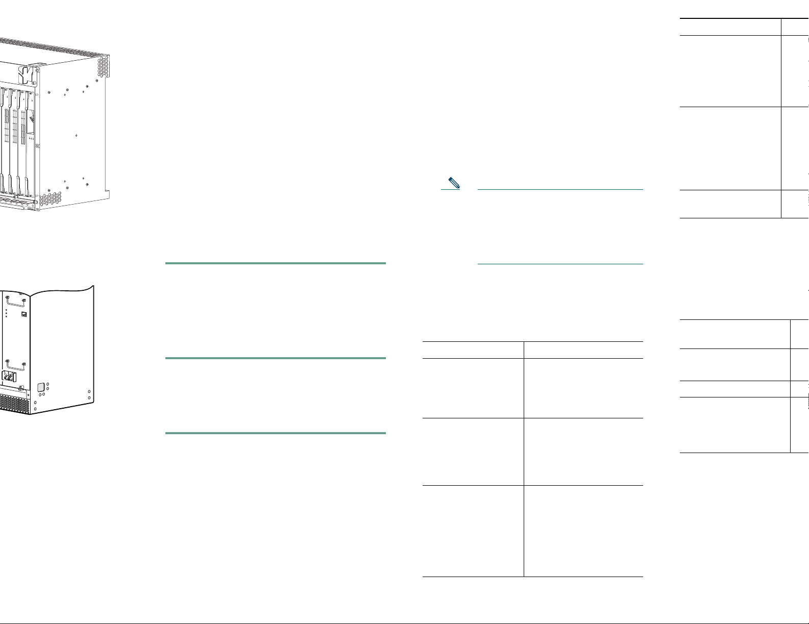
Removing the PRE Module
Use thefollowing procedure toremove the existing
PRE module from the chassis.
Step 1 Attach the ESD wrist strap to the chassis
to ensure you are properly grounded.
Step 2 Power off the router.
Caution Although PRE modules can be
hot-swapped, removing a module
terminates all traffic. We recommend
that you power off the router to
ensure a successful installation.
Step 3 Disconnect all cables from the PRE.
Step 4 Loosen thetop and bottom captivescrews.
Step 5 Pivot both ejector leverssimultaneously to
disengage the module from the backplane.
Step 6 Remove the PRE from the chassis and
place it on an antistatic surface or in an
antistatic bag.
Step 7 If you are replacing a redundant PRE,
repeat steps 3 though 6.
Use the following procedure
module.
Caution To ensure prope
install the prima
you install a red
slot B, wait until
and configured t
slot A before ins
PRE3 in slot B.
Step 1 Attach the ESD wrist
to ensure you are pr
Step 2 Inspect the backplan
chassis to make sure
pins.
Step 3 Slide the module into
feel it seat into the ba
and Figure 2).
Corporate Headquarters
Cisco Systems, Inc.
170 West Tasman Drive
San Jose, CA 95134-1706
USA
http://www.cisco.com
Tel: 408 526-4000
800 553-NETS (6387)
Fax: 408 526-4100
CCVP, the Cisco Logo, and the Cisco Square Bridge logo
Changing the Way We Work, Live, Play, and Learnisa
Access Registrar, Aironet, BPX, Catalyst, CCDA, CCD
Cisco, theCiscoCertified Internetwork Expert logo, Cisc
Systems Capital, the Cisco Systems logo, Cisco U
EtherFast, EtherSwitch, Fast Step, Follow Me Browsi
HomeLink, Internet Quotient, IOS, IP/TV, iQ Exper
Scorecard, iQuick Study, LightStream, Linksys, Meeti
Network Registrar, Packet, PIX, ProConnect, RateMU
StackWise, The Fastest Way to Increase Your Internet
trademarks of Cisco Systems, Inc. and/or its affiliates
countries.
All other trademarks mentioned in this document or We
owners. Theuseof the word partnerdoesnot imply a par
any other company. (0609R)
© 2006 Cisco Systems, Inc. All rights reserved.
Printed in the USA on recycled paper containing 10% po
78-16710-02
Page 2
E
T
e
t
g
R
N
r
e
R
r
R
a
a
l
t
R
R
m
x
i
PERFORMANCE ROUTING ENGINE
• If you need to access the TFTP server
to obtain the full image or the saved
configuration files, enter the
configuration dialog and enter the
information to accessthe TFTP server.
5
6
7
8
CISCO
CISCO
10000
10000
CISCO
FAIL
FAIL
CISCO
10000
10000
FAIL
FAIL
CARRIER
ALARM
CARRIER
LOOP
ALARM
CARRIER
LOOP
ALARM
LOOP
0
0
0
1
1
1
2
2
2
3
3
3
CARRIER
4
4
TX
RX
4
5
5
5
OC–12/STM–4 POS SM–IR
6XCT3–DS0
6XCT3–DS0
6XCT3–DS0
• If you booted the full image, restore
the startup and running configuration
information, and set the variable for
the new image. The upgrade is now
complete.
• If you booted from the helper image:
–
Download the full image.
–
Restore the startup and running
configuration information.
–
32682
Set the boot variable to the new
image.
–
Reload the router.
The upgrade is now complete.
If this sequence does not occur, check the
following:
• Check to see if the LEDs on the other modules
are operating. If not, check for a problem in
the power subsystem.
• Remove the PRE3 and check for bent or
broken pins on the backplane connectors.
• Verify the status of the PRE3s internal
Ethernet interface (ethernet 0/0/0). If this
interface is down it could indicate that the
PRE3 is not fully seated in the slot, or that a
hardware failure occurred.
Note Do not confuse the PRE3 internal
Ethernet interface (ethernet 0/0/0)
with the module’s external Fast
Ethernet interface (fastethernet 0/0/0)
which is used for network
management or remote access.
LED/Switch Descr
STATUS
• On (green)
• Off
• P
•
FAIL
• Off
• On (yellow)
• P
• P
ACO1 switch Disab
alarm
1. Alarm cutoff
3 Technical Sp
o
r
p
c
f
POWER
MISWIRE
FAULT
122201
image from the TFTP server.
Installing a Redundant PRE3
Use the following procedure to install a redundant
PRE3.
Step 1 Repeat Step 1 through Step 8 for slot B
(see Installing the PRE3 Module).
Step 2 Setthe configuration toboot the fullimage
and reload from the console ROMMON
prompt.
2 Troubleshooting
The PRE3 displays the following sequence of
events when booted:
• The FAIL LED lights briefly, followed by a
flashing STATUS LED, and progress messages
appear on the PRE3 display.
• IOS RUN appears after a successful boot.
• The STATUS LED remains on (green).
• Refer to Table 1 for LED and switch
descriptions.
Table 1 LED and Switch Descriptions
LED/Switch Description
ACTIVITY
• On (green)
• Off
LINK
• On (green)
• Off
• Packets are being
transmitted and
received.
• No packet activity.
• Carrier detected and
passing traffic.
• No carrier detected
and not passing
traffic.
CRITICAL
MAJOR
MINOR
• Off
• On (yellow)
• No alarm.
• Alarm condition is
present.
The following table provides
specifications.
Par
Description
PRE3
PRE3 spare
Spe
ES
ES
Weight 9 lb
Powerconsumptionper
PRE3 module
145
no
200
ma
4 Related Docu
The release notes, regulatory
safety information, and user
products are available online
 Loading...