

Page 1

Installing Power Boards in Cisco Ethernet
Switch Network Modules
Product Numbers: PPWR-DCARD-16ESW, PPWR-DCARD-36ESW
This document describes how to install the optional power board for the Cisco Ethernet switch network
module if external -48V power for IP telephones is required.
Network module installation documents provide detailed instructions for network module installation
and cabling. You can access thesedocumentsat: Cisco Product Documentation > Access Servers and
Access Routers > Modular Access Routers > Cisco platform you are using> Hardware installation
documents for Cisco platform you are using > Network module (netmod) installation
This document contains the following sections:
• Safety Information, page 1
• Tools and Equipment Needed, page 2
• Adding an Optional Power Board, page 2
• Obtaining Documentation, page 4
• Obtaining Technical Assistance, page 5
Safety Information
For safety information you need to know before working on your Cisco router, see the Regulatory
Compliance and Safety Information document that accompanied this device.
Warning
Caution Electrostatic discharge (ESD) candamage equipment and impair electrical circuitry.AlwaysfollowESD
Only trained and qualified personnel should be allowed to install or replace this equipment. To see
translations of the warnings that appear in this publication, refer to the
Safety Information
prevention procedures when removing and replacing cards.
Corporate Headquarters:
Cisco Systems, Inc., 170 West Tasman Drive, San Jose, CA 95134-1706 USA
Copyright © 2002. Cisco Systems, Inc. All rights reserved.
Regulatory Compliance and
document that accompanied this device.
Page 2
Tools and Equipment Needed
Tools and Equipment Needed
You need the following tools and equipment to remove and install Compact Flash memory cards:
• ESD-preventive wrist strap
• Antistatic bag or mat
• Number 2 Phillips screwdriver or flat-blade screwdriver
Adding an Optional Power Board
An optional power board can be used if the Ethernet switch network module requires external -48V
power for IP telephones. Installation and configuration of the external power suppy system is described
in the Cisco External Power Supply for Cisco Ethernet Switch Network Modules Installation Guide. Use
the Cisco Network Modules Hardware Installation Guide and platform hardware installation guide for
more information.
Follow this procedure to install power boards:
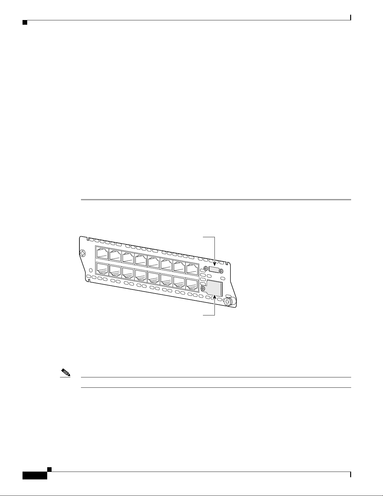
Step 1 Use a Philips screwdriver to remove the cover on the external power board port, as shown in Figure 1.
Figure 1 Power Board Port Cover on the Ethernet Switch Network Module
NMESW16
15x
7x
15x 7x 14x 6x 13x 5x
External power supply port cover
FastEthernet Ports
12x 4x
11x 3x 10x 2x 9x 1x 8x 0x
8x
0x
-48V
Ext
Pwr
GE
10/100/
1000
Base-Tx
EN
62426
Gigabit Ethernet port cover
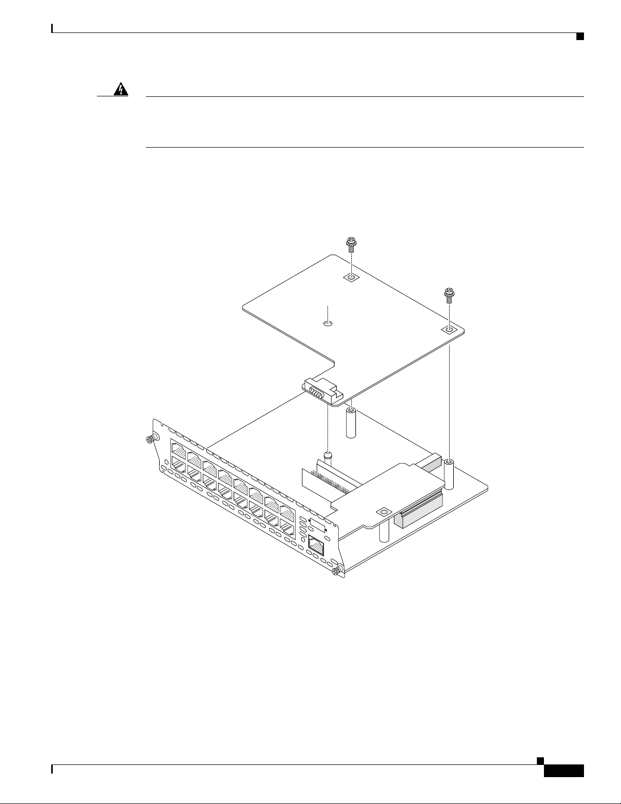
Step 2 Remove the thumbscrews on either side of the power board port. Put these in a safe place as they will be
replaced once the power board is installed.
Step 3 Guide the external connector through the power board port opening on the card faceplate.
Step 4 Insert the connector on the power board into the connector on the network module. See Figure 2 for
16-port Ethernet switch network modules and Figure 3 for 36-port Ethernet switch network modules.
Note Be sure to press firmly on the power board until the board seats onto the connector.
Step 5 Insert the screws from the board installation kit through the power board into the standoffs on the
network module.
Step 6 Replace the thumbscrews on either side of the power board port. Make sure the thumbscrews are
tightened firmly.
Installing Power Boards in Cisco Ethernet Switch Network Modules
2
78-14282-02
Page 3
Adding an Optional Power Board
Warning
Donotconnect the external power supplycabletothe power connector on thefrontofthe network
module until the network module has been inserted into the router chassis. Tosee translations of
the warnings that appear in this publication, refer to the
Information
document that accompanied this device.
Regulatory Compliance and Safety
Step 7 After installing the network module into the chassis, connect the power cable to the power module
connector on the front of the network module. See the Cisco External Power Supply for Cisco Ethernet
Switch Network Modules Installation Guide for more information.
Figure 2 Installing a Power Board in a 16-Port Ethernet Switch Network Module
NMESW16
15x
7x
15x 7x 14x 6x 13x 5x
FastEthernet Ports
12x 4x
11x 3x 10x 2x 9x 1x 8x 0x
8x
Ext
-48V
Pwr
0x
GE
10/100/
1000
Base-Tx
EN
62350
78-14282-02
Installing Power Boards in Cisco Ethernet Switch Network Modules
3
Page 4

Obtaining Documentation
Figure 3 Installing a Power Board in a 36-Port Ethernet Switch Network Module
NMDESW36
35x
GE1
10/100/1000
Base-Tx
17x
35x 17x 34x 16x
33x 15x 32x 14x 31x 13x 30x 12x
FastEthernet Ports
29x 11x 28x 10x
27x 9x 26x 8x 25x 17 24x 6x
Obtaining Documentation
The following sections provide sources for obtaining documentation from Cisco Systems.
World Wide Web
You can access the most current Cisco documentation on the World Wide Web at the following sites:
• http://www.cisco.com
• http://www-china.cisco.com
• http://www-europe.cisco.com
23x 5x 22x 4x
21x 3x 20x 2x 19x 1x 18x 0x
18x
Ext
-48V
Pwr
8x
GE
0x
10/100/
1000
Base-Tx
EN
72275
Installing Power Boards in Cisco Ethernet Switch Network Modules
4
78-14282-02
Page 5

Documentation CD-ROM
Cisco documentation and additional literature are available in a CD-ROM package, which ships
with your product. The Documentation CD-ROM is updated monthly and may be more current than
printed documentation. The CD-ROM package is available as a single unit or as an annual subscription.
Ordering Documentation
Cisco documentation is available in the following ways:
• Registered Cisco Direct Customers can order Cisco Product documentation from the Networking
Products MarketPlace:
http://www.cisco.com/cgi-bin/order/order_root.pl
• Registered Cisco.com users can order the Documentation CD-ROMthrough the online Subscription
Store:
http://www.cisco.com/go/subscription
• Nonregistered Cisco.com users can order documentation through a local account representative by
calling Cisco corporate headquarters (California, USA) at 408 526-7208 or, in North America, by
calling 800 553-NETS(6387).
Obtaining Technical Assistance
Documentation Feedback
If you are reading Cisco product documentation on the World Wide Web, you can submit technical
comments electronically. Click Feedback in the toolbar and select Documentation. After you complete
the form, click Submit to send it to Cisco.
You can e-mail your comments to bug-doc@cisco.com.
To submit your comments by mail, use the response card behind the front cover of your document, or
write to the following address:
Attn Document Resource Connection
Cisco Systems, Inc.
170 West Tasman Drive
San Jose, CA 95134-9883
We appreciate your comments.
Obtaining Technical Assistance
Cisco provides Cisco.com as a starting point for all technical assistance. Customers and partners can
obtain documentation, troubleshooting tips, and sample configurationsfromonline tools. For Cisco.com
registered users, additional troubleshooting tools are available from the TAC website.
78-14282-02
Installing Power Boards in Cisco Ethernet Switch Network Modules
5
Page 6

Obtaining Technical Assistance
Cisco.com
Cisco.com is the foundation of a suite of interactive, networked services that provides immediate, open
access to Cisco information and resources at anytime, from anywhere in the world. This highly
integrated Internet application is a powerful, easy-to-use tool for doing business with Cisco.
Cisco.com provides a broad range of features and services to help customers and partners streamline
business processes and improve productivity. Through Cisco.com, you can findinformation about Cisco
and our networking solutions, services, and programs. In addition, you can resolve technical issues with
online technical support, download and test software packages, and order Cisco learning materials and
merchandise. Valuable online skill assessment, training, and certification programs are also available.
Customers and partners can self-register on Cisco.com to obtain additional personalized information and
services. Registered users can order products, check on the status of an order, access technical support,
and view benefits specific to their relationships with Cisco.
To access Cisco.com, go to the following website:
http://www.cisco.com
Technical Assistance Center
The Cisco TAC website is available to all customers who need technical assistance with a Cisco product
or technology that is under warranty or covered by a maintenance contract.
Contacting TAC by Using the Cisco TAC Website
If you have a priority level 3 (P3) or priority level 4 (P4) problem, contact TAC by going to the TAC
website:
http://www.cisco.com/tac
P3 and P4 level problems are defined as follows:
• P3—Your network performance is degraded.Network functionality is noticeably impaired, but most
business operations continue.
• P4—You need information or assistance on Cisco product capabilities, product installation, or basic
product configuration.
In each of the above cases, use the Cisco TAC website to quickly find answers to your questions.
To register for Cisco.com, go to the following website:
http://www.cisco.com/register/
If you cannot resolve your technical issue by using the TAC online resources, Cisco.com registered users
can open a case online by using the TAC Case Open tool at the following website:
http://www.cisco.com/tac/caseopen
Contacting TAC by Telephone
If you have a priority level 1 (P1) or priority level 2 (P2) problem, contact TAC by telephone and
immediately open a case. Toobtain a directory of toll-free numbers for your country,go to the following
website:
http://www.cisco.com/warp/public/687/Directory/DirTAC.shtml
Installing Power Boards in Cisco Ethernet Switch Network Modules
6
78-14282-02
Page 7

Obtaining Technical Assistance
P1 and P2 level problems are defined as follows:
• P1—Your production network is down, causing a critical impact to business operations if service is
not restored quickly. No workaround is available.
• P2—Your production network is severely degraded, affecting significant aspects of your business
operations. No workaround is available.
Use this document with the Cisco 2600 Series, 3600 Series, and 3700 Series Regulatory Compliance and Safety Information document.
CCIP, the Cisco Powered Network mark, the Cisco Systems Verified logo, Cisco Unity, Fast Step, Follow Me Browsing, FormShare, Internet Quotient, iQ Breakthrough, iQ
Expertise, iQ FastTrack, the iQ Logo, iQ Net Readiness Scorecard, Networking Academy, ScriptShare, SMARTnet, TransPath, and Voice LAN are trademarks of Cisco Systems,
Inc.; Changing the Way WeWork, Live, Play, and Learn, Discover All That’s Possible, The Fastest Way to Increase YourInternet Quotient, and iQuick Study are service marks of
Cisco Systems, Inc.; and Aironet, ASIST, BPX, Catalyst, CCDA,CCDP, CCIE, CCNA, CCNP, Cisco, the Cisco Certified Internetwork Expert logo, Cisco IOS,theCiscoIOSlogo,
Cisco Press, Cisco Systems, Cisco Systems Capital, the Cisco Systems logo, Empowering the Internet Generation, Enterprise/Solver,EtherChannel,EtherSwitch, GigaStack, IOS,
IP/TV, LightStream, MGX, MICA, the Networkers logo, Network Registrar, Packet, PIX, Post-Routing, Pre-Routing, RateMUX, Registrar, SlideCast, StrataView Plus, Stratm,
SwitchProbe, TeleRouter, and VCO are registered trademarks of Cisco Systems, Inc. and/or its affiliates in the U.S. and certain other countries.
All other trademarks mentioned in this document or Web site are the property of their respective owners. The use of the word partner does not imply a partnership relationship
between Cisco and any other company. (0201R)
Copyright ©2001-2002, Cisco Systems, Inc.
All rights reserved.
Installing Power Boards in Cisco Ethernet Switch Network Modules
78-14282-02
7
Page 8

Obtaining Technical Assistance
Installing Power Boards in Cisco Ethernet Switch Network Modules
8
78-14282-02
 Loading...