

Page 1

Cisco Redundant Power System
Hardware Installation Guide
Corporate Headquarters
Cisco Systems, Inc.
170 West Tasman Drive
San Jose, CA 95134-1706
USA
http://www.cisco.com
Tel: 408 526-4000
800 553-NETS (6387)
Fax: 408 526-4100
Text Part Number: OL-3654-01
Page 2

THE SPECIFICATIONS AND INFORMATION REGARDING THE PRODUCTS IN THIS MANUAL ARE SUBJECT TO CHANGE WITHOUT
NOTICE. ALL STATEMENTS, INFORMATION, AND RECOMMENDATIONS IN THIS MANUAL ARE BELIEVED TO BE ACCURATE BUT
ARE PRESENTED WITHOUT WARRANTY OF ANY KIND, EXPRESS OR IMPLIED. USERS MUST TAKE FULL RESPONSIBILITY FOR
THEIR APPLICATION OF ANY PRODUCTS.
THE SOFTWARE LICENSE AND LIMITED WARRANTY FOR THE ACCOMPANYING PRODUCT ARE SET FORTH IN THE INFORMATION
PACKET THAT SHIPPED WITH THE PRODUCT AND ARE INCORPORATED HEREIN BY THIS REFERENCE. IF YOU ARE UNABLE TO
LOCATE THE SOFTWARE LICENSE OR LIMITED WARRANTY, CONTACT YOUR CISCO REPRESENTATIVE FOR A COPY.
The following information is for FCC compliance of Class A devices: This equipment has been tested and found to comply with the limits for a Class
A digital device, pursuant to part 15 of the FCC rules. These limits are designed to provide reasonable protection against harmful interference when
the equipment is operated in a commercial environment. This equipment generates, uses, and can radiate radio-frequency energy and, if not installed
and used in accordance with the instruction manual, may cause harmful interference to radio communications. Operation of this equipment in a
residential area is likely to cause harmful interference, in which case users will be required to correct the interference at their own expense.
The following information is for FCC compliance of Class B devices: The equipment described in this manual generates and may radiate
radio-frequency energy. If it is not installed in accordance with Cisco’s installation instructions, it may cause interference with radio and television
reception. This equipment has been tested and found to comply with the limits for a Class B digital device in accordance with the specifications in
part 15 of the FCC rules. These specifications are designed to provide reasonable protection against such interference in a residential installation.
However, there is no guarantee that interference will not occur in a particular installation.
Modifying the equipment without Cisco’s written authorization may result in the equipment no longer complying with FCC requirements for Class
A or Class B digital devices. In that event, your right to use the equipment may be limited by FCC regulations, and you may be required to correct
any interference to radio or television communications at your own expense.
You can determine whether your equipment is causing interference by turning it off. If the interference stops, it was probably caused by the Cisco
equipment or one of its peripheral devices. If the equipment causes interference to radio or television reception, try to correct the interference by
using one or more of the following measures:
• Turn the television or radio antenna until the interference stops.
• Move the equipment to one side or the other of the television or radio.
• Move the equipment farther away from the television or radio.
• Plug the equipment into an outlet that is on a different circuit from the television or radio. (That is, make certain the equipment and the television
or radio are on circuits controlled by different circuit breakers or fuses.)
Modifications to this product not authorized by Cisco Systems, Inc. could void the FCC approval and negate your authority to operate the product.
The Cisco implementation of TCP header compression is an adaptation of a program developed by the University of California, Berkeley (UCB) as
part of UCB’s public domain version of the UNIX operating system. All rights reserved. Copyright © 1981, Regents of the University of California.
NOTWITHSTANDING ANY OTHER WARRANTY HEREIN, ALL DOCUMENT FILES AND SOFTWARE OF THESE SUPPLIERS ARE
PROVIDED “AS IS” WITH ALL FAULTS. CISCO AND THE ABOVE-NAMED SUPPLIERS DISCLAIM ALL WARRANTIES, EXPRESSED
OR IMPLIED, INCLUDING, WITHOUT LIMITATION, THOSE OF MERCHANTABILITY, FITNESS FOR A PARTICULAR PURPOSE AND
NONINFRINGEMENT OR ARISING FROM A COURSE OF DEALING, USAGE, OR TRADE PRACTICE.
IN NO EVENT SHALL CISCO OR ITS SUPPLIERS BE LIABLE FOR ANY INDIRECT, SPECIAL, CONSEQUENTIAL, OR INCIDENTAL
DAMAGES, INCLUDING, WITHOUT LIMITATION, LOST PROFITS OR LOSS OR DAMAGE TO DATA ARISING OUT OF THE USE OR
INABILITY TO USE THIS MANUAL, EVEN IF CISCO OR ITS SUPPLIERS HAVE BEEN ADVISED OF THE POSSIBILITY OF SUCH
DAMAGES
Page 3

.
CCIP, CCSP, the Cisco Arrow logo, the Cisco Powered Network mark, the Cisco Systems Verified logo, Cisco Unity, Follow Me Browsing, FormShare,
iQ Breakthrough, iQ FastTrack, the iQ Logo, iQ Net Readiness Scorecard, Networking Academy, ScriptShare, SMARTnet, TransPath, and Voice LAN
are trademarks of Cisco Systems, Inc.; Changing the Way We Work, Live, Play, and Learn, The Fastest Way to Increase Your Internet Quotient, and
iQuick Study are service marks of Cisco Systems, Inc.; and Aironet, ASIST, BPX, Catalyst, CCDA, CCDP, CCIE, CCNA, CCNP, Cisco, the Cisco
Certified Internetwork Expert logo, Cisco IOS, the Cisco IOS logo, Cisco Press, Cisco Systems, Cisco Systems Capital, the Cisco Systems logo,
Empowering the Internet Generation, Enterprise/Solver, EtherChannel, EtherSwitch, Fast Step, GigaStack, Internet Quotient, IOS, IP/TV, iQ Expertise,
LightStream, MGX, MICA, the Networkers logo, Network Registrar, Pac ke t, PIX, Post-Routing, Pre-Routing, RateMUX, Registrar, SlideCast,
StrataView Plus, Stratm, SwitchProbe, TeleRouter, and VCO are registered trademarks of Cisco Systems, Inc. and/or its affiliates in the U.S. and certain
other countries.
All other trademarks mentioned in this document or Web site are the property of their respective owners. The use of the word partner does not imply a
partnership relationship between Cisco and any other company. (0301R)
Cisco Redundant Power System Hardware Installation Guide
Copyright © 1998-2003, Cisco Systems, Inc.
All rights reserved.
Page 4

Page 5

Preface ix
Audience x
Organization x
Related Publications x
Notes, Cautions, and Warnings xi
Obtaining Documentation xviii
World Wide Web xviii
Documentation CD-ROM xviii
Ordering Documentation xviii
Documentation Feedback xix
Obtaining Technical Assistance xix
Cisco.com xix
CONTENTS
CHAPTER
OL-3654-01
Technical Assistance Center xx
1 Overview 1-1
Features 1-1
Supported Devices and Configurations 1-2
Quasi-Redundant Configuration 1-4
Fully Redundant Configuration 1-5
Redundant with Reboot 1-6
Quasi- and Fully Redundant Mixed Configuration 1-7
Front and Rear Panel Descriptions 1-8
Cisco TAC Web Site xx
Cisco TAC Escalation Center xxi
Cisco Redundant Power System Hardware Installation Guide
v
Page 6

Contents
LEDs 1-9
Safety Recommendations 1-11
Safety Warnings 1-12
Safety with Electricity 1-12
CHAPTER
CHAPTER
2 Installing the Cisco RPS 2-1
Setting the Cisco RPS on a Desktop 2-3
Rack-Mounting the Cisco RPS 2-3
Planning Your Rack-Mount Installation 2-4
Tools and Equipment Required 2-5
Identifying Rack-Mount Brackets 2-5
Attaching Brackets 2-6
Mounting the Chassis in a Rack 2-8
3 Connection Requirements 3-1
Tools and Equipment Required 3-2
Cabling Options 3-2
Ordering Cables 3-3
Upgrade Kit with Power Adapter Plate for Routers and Concentrators 3-6
CHAPTER
4 Connecting the Cisco RPS 4-1
Power Considerations 4-1
Connecting Hubs 4-2
Connecting Switches 4-6
Connecting Routers and the Cisco MC3810 Concentrator 4-13
CHAPTER
5 Troubleshooting the Cisco RPS 5-1
Reading the LEDs 5-1
Cisco Redundant Power System Hardware Installation Guide
vi
OL-3654-01
Page 7

Contents
Displaying Status 5-5
Error Messages on Cisco 2600 Series and Cisco 3620, Cisco 3640, and Cisco 3725
Routers
5-6
DC Failure 5-6
AC Failure 5-7
Fan Failure 5-9
Temperature Error 5-10
Multiple Errors 5-12
Replacing an External Device 5-13
Getting Technical Support 5-14
APPENDIX
I
NDEX
A Technical Specifications A-1
OL-3654-01
Cisco Redundant Power System Hardware Installation Guide
vii
Page 8

Contents
Cisco Redundant Power System Hardware Installation Guide
viii
OL-3654-01
Page 9

Preface
The Cisco Redundant Power System Hardware Installation Guide documents
operation and features of the Cisco 600W Redundant Power System (RPS). It
provides installation instructions and troubleshooting information for the RPS,
which can be used to support the following current product lines:
• FastHub 400 series hubs and Cisco 1516M hubs (also known as the
HP 10BASE-T Hub-16M)
• Catalyst 1900 series switches, Catalyst 2820 series switches, Catalyst 2900
series XL switches, and Catalyst 3500 series XL switches
• Cisco 2500 series routers and access servers, Cisco 3620, 3640, and 3725
routers, and Cisco 2600 series and Cisco 4000 series routers
• Cisco MC3810 series multiservice concentrators
Cisco documentation and additional literature are contained in a CD-ROM
package, which ships with your product. The Documentation CD-ROM, a
member of the Cisco Connection Family, is updated monthly. Therefore, it might
be more current than printed documentation. To order additional copies of the
Documentation CD-ROM, contact your local sales representative or call customer
service. The CD-ROM package is available as a single package or as an annual
subscription. You can also access Cisco documentation on the World Wide Web
at http://www.cisco.com, http://www-china.cisco.com, or
http://www-europe.cisco.com.
If you are reading Cisco product documentation on the World Wide Web, you can
submit comments electronically. Click Feedback in the toolbar and select
Documentation. After you complete the form, click Submit to send it to Cisco.
We appreciate your comments.
OL-3654-01
Cisco Redundant Power System Hardware Installation Guide
ix
Page 10

Audience
Audience
This publication is designed for people who have some experience installing
networking equipment such as routers, hubs, servers, and switches. We assume
that the person installing and troubleshooting the Cisco RPS is familiar with
electronic circuitry and wiring practices and has experience as an electronic or
electromechanical technician.
Organization
Table 1 describes the document organization.
Table 1 Document Organization
Preface
Chapter Title Description
Chapter 1
Chapter 2
Chapter 3
Chapter 4
Chapter 5
Appendix A
Overview Gives an overview of the Cisco RPS, features, supported
devices, configurations, physical description including
LEDs, and safety recommendations.
Installing the Cisco RPS Provides instructions for setting the Cisco RPS on a
desktop or for rack-mounting the Cisco RPS.
Connection Requirements Explains the cabling options for connecting the Cisco RPS
to external devices and how to order cabling and upgrade
kits appropriate for each device.
Connecting the Cisco RPS Provides procedures for connecting the Cisco RPS to the
supported external devices (see Table 1-1 on page 3) and
steps for replacing a failed external device receiving power
from the Cisco RPS.
Troubleshooting the
Cisco RPS
Technical Specifications Lists the technical specifications for the Cisco RPS.
Describes how to identify and resolve some of the
problems that might arise with the Cisco RPS.
Cisco Redundant Power System Hardware Installation Guide
x
OL-3654-01
Page 11

Preface
Related Publications
For more related information, refer to the installation and configuration guides for
the specific switch or router. For routers and concentrators that require a power
adapter plate, also refer to the instructions that ship with the plate.
Notes, Cautions, and Warnings
Notes, cautions, and warnings use the following conventions and symbols.
Note Means reader take note. Notes contain helpful suggestions or references to
additional information and material.
Related Publications
Caution Means reader be careful. In this situation, you might do something that could
result in equipment damage or loss of data.
Warning
IMPORTANT SAFETY INSTRUCTIONS
This warning symbol means danger. You are in a situation that could cause
bodily injury. Before you work on any equipment, be aware of the hazards
involved with electrical circuitry and be familiar with standard practices for
preventing accidents. To see translations of the warnings that appear in this
publication, refer to the translated safety warnings that accompanied this
device.
Note: SAVE THESE INSTRUCTIONS
Note: This documentation is to be used in conjunction with the specific
product installation guide that shipped with the product. Please refer to the
Installation Guide, Configuration Guide, or other enclosed additional
documentation for further details.
OL-3654-01
Cisco Redundant Power System Hardware Installation Guide
xi
Page 12

Notes, Cautions, and Warnings
Preface
Waarschuwing
Varoitus
BELANGRIJKE VEILIGHEIDSINSTRUCTIES
Dit waarschuwingssymbool betekent gevaar. U verkeert in een situatie die
lichamelijk letsel kan veroorzaken. Voordat u aan enige apparatuur gaat
werken, dient u zich bewust te zijn van de bij elektrische schakelingen
betrokken risico's en dient u op de hoogte te zijn van de standaard praktijken
om ongelukken te voorkomen. Voor een vertaling van de waarschuwingen die
in deze publicatie verschijnen, dient u de vertaalde
veiligheidswaarschuwingen te raadplegen die bij dit apparaat worden
geleverd.
Opmerking BEWAAR DEZE INSTRUCTIES.
Opmerking Deze documentatie dient gebruikt te worden in combinatie met de
installatiehandleiding voor het specifieke product die bij het product wordt
geleverd. Raadpleeg de installatiehandleiding, configuratiehandleiding of
andere verdere ingesloten documentatie voor meer informatie.
TÄRKEITÄ TURVALLISUUTEEN LIITTYVIÄ OHJEITA
Tämä varoitusmerkki merkitsee vaaraa. Olet tilanteessa, joka voi johtaa
ruumiinvammaan. Ennen kuin työskentelet minkään laitteiston parissa, ota
selvää sähkökytkentöihin liittyvistä vaaroista ja tavanomaisista
onnettomuuksien ehkäisykeinoista. Tässä asiakirjassa esitettyjen varoitusten
käännökset löydät laitteen mukana toimitetuista ohjeista.
xii
Huomautus SÄILYTÄ NÄMÄ OHJEET
Huomautus Tämä asiakirja on tarkoitettu käytettäväksi yhdessä tuotteen
mukana tulleen asennusoppaan kanssa. Katso lisätietoja asennusoppaasta,
kokoonpano-oppaasta ja muista mukana toimitetuista asiakirjoista.
Cisco Redundant Power System Hardware Installation Guide
OL-3654-01
Page 13

Preface
Notes, Cautions, and Warnings
Attention
Warnung
IMPORTANTES INFORMATIONS DE SÉCURITÉ
Ce symbole d'avertissement indique un danger. Vous vous trouvez dans une
situation pouvant causer des blessures ou des dommages corporels. Avant de
travailler sur un équipement, soyez conscient des dangers posés par les
circuits électriques et familiarisez-vous avec les procédures couramment
utilisées pour éviter les accidents. Pour prendre connaissance des
traductions d'avertissements figurant dans cette publication, consultez les
consignes de sécurité traduites qui accompagnent cet appareil.
Remarque CONSERVEZ CES INFORMATIONS
Remarque Cette documentation doit être utilisée avec le guide spécifique
d'installation du produit qui accompagne ce dernier. Veuillez vous reporter au
Guide d'installation, au Guide de configuration, ou à toute autre
documentation jointe pour de plus amples renseignements.
WICHTIGE SICHERHEITSANWEISUNGEN
Dieses Warnsymbol bedeutet Gefahr. Sie befinden sich in einer Situation, die
zu einer Körperverletzung führen könnte. Bevor Sie mit der Arbeit an
irgendeinem Gerät beginnen, seien Sie sich der mit elektrischen
Stromkreisen verbundenen Gefahren und der Standardpraktiken zur
Vermeidung von Unfällen bewusst. Übersetzungen der in dieser
Veröffentlichung enthaltenen Warnhinweise sind im Lieferumfang des Geräts
enthalten.
OL-3654-01
Hinweis BEWAHREN SIE DIESE SICHERHEITSANWEISUNGEN AUF
Hinweis Dieses Handbuch ist zum Gebrauch in Verbindung mit dem
Installationshandbuch für Ihr Gerät bestimmt, das dem Gerät beiliegt.
Entnehmen Sie bitte alle weiteren Informationen dem Handbuch
(Installations- oder Konfigurationshandbuch o. Ä.) für Ihr spezifisches Gerät.
Cisco Redundant Power System Hardware Installation Guide
xiii
Page 14

Notes, Cautions, and Warnings
Preface
Figyelem!
Avvertenza
FONTOS BIZTONSÁGI ELÕÍRÁSOK
Ez a figyelmezetõ jel veszélyre utal. Sérülésveszélyt rejtõ helyzetben van.
Mielõtt bármely berendezésen munkát végezte, legyen figyelemmel az
elektromos áramkörök okozta kockázatokra, és ismerkedjen meg a szokásos
balesetvédelmi eljárásokkal. A kiadványban szereplõ figyelmeztetések
fordítása a készülékhez mellékelt biztonsági figyelmeztetések között
található.
Megjegyzés ÕRIZZE MEG EZEKET AZ UTASÍTÁSOKAT!
Megjegyzés Ezt a dokumentációt a készülékhez mellékelt üzembe helyezési
útmutatóval együtt kell használni. További tudnivalók a mellékelt Üzembe
helyezési útmutatóban (Installation Guide), Konfigurációs útmutatóban
(Configuration Guide) vagy más dokumentumban találhatók.
IMPORTANTI ISTRUZIONI SULLA SICUREZZA
Questo simbolo di avvertenza indica un pericolo. La situazione potrebbe
causare infortuni alle persone. Prima di intervenire su qualsiasi
apparecchiatura, occorre essere al corrente dei pericoli relativi ai circuiti
elettrici e conoscere le procedure standard per la prevenzione di incidenti.
Per le traduzioni delle avvertenze riportate in questo documento, vedere le
avvertenze di sicurezza che accompagnano questo dispositivo.
xiv
Nota CONSERVARE QUESTE ISTRUZIONI
Nota La presente documentazione va usata congiuntamente alla guida di
installazione specifica spedita con il prodotto. Per maggiori informazioni,
consultare la Guida all'installazione, la Guida alla configurazione o altra
documentazione acclusa.
Cisco Redundant Power System Hardware Installation Guide
OL-3654-01
Page 15

Preface
Notes, Cautions, and Warnings
Advarsel
Aviso
VIKTIGE SIKKERHETSINSTRUKSJONER
Dette varselssymbolet betyr fare. Du befinner deg i en situasjon som kan
forårsake personskade. Før du utfører arbeid med utstyret, bør du være
oppmerksom på farene som er forbundet med elektriske kretssystemer, og du
bør være kjent med vanlig praksis for å unngå ulykker. For å se oversettelser
av advarslene i denne publikasjonen, se de oversatte sikkerhetsvarslene som
følger med denne enheten.
Merk TA VARE PÅ DISSE INSTRUKSJONENE
Merk Denne dokumentasjonen skal brukes i forbindelse med den spesifikke
installasjonsveiledningen som fulgte med produktet. Vennligst se
installasjonsveiledningen, konfigureringsveiledningen eller annen vedlagt
tilleggsdokumentasjon for detaljer.
INSTRUÇÕES IMPORTANTES DE SEGURANÇA
Este símbolo de aviso significa perigo. O utilizador encontra-se numa
situação que poderá ser causadora de lesões corporais. Antes de iniciar a
utilização de qualquer equipamento, tenha em atenção os perigos envolvidos
no manuseamento de circuitos eléctricos e familiarize-se com as práticas
habituais de prevenção de acidentes. Para ver traduções dos avisos incluídos
nesta publicação, consulte os avisos de segurança traduzidos que
acompanham este dispositivo.
OL-3654-01
Nota GUARDE ESTAS INSTRUÇÕES
Nota Esta documentação destina-se a ser utilizada em conjunto com o
manual de instalação incluído com o produto específico. Consulte o manual
de instalação, o manual de configuração ou outra documentação adicional
inclusa, para obter mais informações.
Cisco Redundant Power System Hardware Installation Guide
xv
Page 16

Notes, Cautions, and Warnings
Preface
¡Advertencia!
Varning!
INSTRUCCIONES IMPORTANTES DE SEGURIDAD
Este símbolo de aviso indica peligro. Existe riesgo para su integridad física.
Antes de manipular cualquier equipo, considere los riesgos de la corriente
eléctrica y familiarícese con los procedimientos estándar de prevención de
accidentes. Vea las traducciones de las advertencias que acompañan a este
dispositivo.
Nota GUARDE ESTAS INSTRUCCIONES
Nota Esta documentación está pensada para ser utilizada con la guía de
instalación del producto que lo acompaña. Si necesita más detalles, consulte
la Guía de instalación, la Guía de configuración o cualquier documentación
adicional adjunta.
VIKTIGA SÄKERHETSANVISNINGAR
Denna varningssignal signalerar fara. Du befinner dig i en situation som kan
leda till personskada. Innan du utför arbete på någon utrustning måste du vara
medveten om farorna med elkretsar och känna till vanliga förfaranden för att
förebygga olyckor. Se översättningarna av de varningsmeddelanden som finns
i denna publikation, och se de översatta säkerhetsvarningarna som medföljer
denna anordning.
xvi
OBS! SPARA DESSA ANVISNINGAR
OBS! Denna dokumentation ska användas i samband med den specifika
produktinstallationshandbok som medföljde produkten. Se
installationshandboken, konfigurationshandboken eller annan bifogad
ytterligare dokumentation för närmare detaljer.
Cisco Redundant Power System Hardware Installation Guide
OL-3654-01
Page 17
Preface
Notes, Cautions, and Warnings
OL-3654-01
Cisco Redundant Power System Hardware Installation Guide
xvii
Page 18

Obtaining Documentation
Obtaining Documentation
These sections explain how to obtain documentation from Cisco Systems.
World Wide Web
You can access the most current Cisco documentation on the World Wide Web at
this URL:
http://www.cisco.com
Translated documentation is available at this URL:
http://www.cisco.com/public/countries_languages.shtml
Preface
Documentation CD-ROM
Cisco documentation and additional literature are available in a Cisco
Documentation CD-ROM package, which is shipped with your product. The
Documentation CD-ROM is updated monthly and may be more current than
printed documentation. The CD-ROM package is available as a single unit or
through an annual subscription.
Ordering Documentation
You can order Cisco documentation in these ways:
• Registered Cisco.com users (Cisco direct customers) can order Cisco product
documentation from the Networking Products MarketPlace:
http://www.cisco.com/cgi-bin/order/order_root.pl
• Registered Cisco.com users can order the Documentation CD-ROM through
the online Subscription Store:
http://www.cisco.com/go/subscription
• Nonregistered Cisco.com users can order documentation through a local
account representative by calling Cisco Systems Corporate Headquarters
(California, U.S.A.) at 408 526-7208 or, elsewhere in North America, by
calling 800 553-NETS (6387).
Cisco Redundant Power System Hardware Installation Guide
xviii
OL-3654-01
Page 19

Preface
Documentation Feedback
You can submit comments electronically on Cisco.com. In the Cisco
Documentation home page, click the Fax or Email option in the “Leave
Feedback” section at the bottom of the page.
You can e-mail your comments to bug-doc@cisco.com.
You can submit your comments by mail by using the response card behind the
front cover of your document or by writing to the following address:
Cisco Systems
Attn: Document Resource Connection
170 West Tasman Drive
San Jose, CA 95134-9883
We appreciate your comments.
Obtaining Technical Assistance
Obtaining Technical Assistance
Cisco provides Cisco.com as a starting point for all technical assistance.
Customers and partners can obtain online documentation, troubleshooting tips,
and sample configurations from online tools by using the Cisco Technical
Assistance Center (TAC) Web Site. Cisco.com registered users have complete
access to the technical support resources on the Cisco TAC Web Site.
Cisco.com
Cisco.com is the foundation of a suite of interactive, networked services that
provides immediate, open access to Cisco information, networking solutions,
services, programs, and resources at any time, from anywhere in the world.
Cisco.com is a highly integrated Internet application and a powerful, easy-to-use
tool that provides a broad range of features and services to help you with these
tasks:
• Streamline business processes and improve productivity
• Resolve technical issues with online support
• Download and test software packages
OL-3654-01
Cisco Redundant Power System Hardware Installation Guide
xix
Page 20

Obtaining Technical Assistance
• Order Cisco learning materials and merchandise
• Register for online skill assessment, training, and certification programs
If you want to obtain customized information and service, you can self-register on
Cisco.com. To access Cisco.com, go to this URL:
http://www.cisco.com
Technical Assistance Center
The Cisco Technical Assistance Center (TAC) is available to all customers who
need technical assistance with a Cisco product, technology, or solution. Two
levels of support are available: the Cisco TAC Web Site and the Cisco TAC
Escalation Center.
Cisco TAC inquiries are categorized according to the urgency of the issue:
Preface
• Priority level 4 (P4)—You need information or assistance concerning Cisco
• Priority level 3 (P3)—Your network performance is degraded. Network
• Priority level 2 (P2)—Your production network is severely degraded,
• Priority level 1 (P1)—Your production network is down, and a critical impact
The Cisco TAC resource that you choose is based on the priority of the problem
and the conditions of service contracts, when applicable.
Cisco TAC Web Site
You can use the Cisco TAC Web Site to resolve P3 and P4 issues yourself, saving
both cost and time. The site provides around-the-clock access to online tools,
knowledge bases, and software. To access the Cisco TAC Web Site, go to this
URL:
product capabilities, product installation, or basic product configuration.
functionality is noticeably impaired, but most business operations continue.
affecting significant aspects of business operations. No workaround is
available.
to business operations will occur if service is not restored quickly. No
workaround is available.
http://www.cisco.com/tac
Cisco Redundant Power System Hardware Installation Guide
xx
OL-3654-01
Page 21

Preface
All customers, partners, and resellers who have a valid Cisco service contract have
complete access to the technical support resources on the Cisco TAC Web Site.
The Cisco TAC Web Site requires a Cisco.com login ID and password. If you have
a valid service contract but do not have a login ID or password, go to this URL to
register:
http://www.cisco.com/register/
If you are a Cisco.com registered user, and you cannot resolve your technical
issues by using the Cisco TAC Web Site, you can open a case online by using the
TAC Case Open tool at this URL:
http://www.cisco.com/tac/caseopen
If you have Internet access, we recommend that you open P3 and P4 cases through
the Cisco TAC Web Site.
Cisco TAC Escalation Center
Obtaining Technical Assistance
The Cisco TAC Escalation Center addresses priority level 1 or priority level 2
issues. These classifications are assigned when severe network degradation
significantly impacts business operations. When you contact the TAC Escalation
Center with a P1 or P2 problem, a Cisco TAC engineer automatically opens a case.
To obtain a directory of toll-free Cisco TAC telephone numbers for your country,
go to this URL:
http://www.cisco.com/warp/public/687/Directory/DirTAC.shtml
Before calling, please check with your network operations center to determine the
level of Cisco support services to which your company is entitled: for example,
SMARTnet, SMARTnet Onsite, or Network Supported Accounts (NSA). When
you call the center, please have available your service agreement number and your
product serial number.
OL-3654-01
Cisco Redundant Power System Hardware Installation Guide
xxi
Page 22

Obtaining Technical Assistance
Preface
Cisco Redundant Power System Hardware Installation Guide
xxii
OL-3654-01
Page 23

CHAPTER
1
Overview
The Cisco 600W Redundant Power System (RPS) provides power system
redundancy to external devices such as routers, switches, and hubs. The system
includes two fully redundant AC input power modules and four DC output power
modules for connection to external devices. The Cisco RPS supports
quasi-redundant, fully redundant, or redundant-with-reboot configurations,
depending upon the external device.
This chapter provides an overview of the Cisco RPS features, including the
supported external devices and power configurations, in the following sections:
• Features, page 1-1
Features
OL-3654-01
• Supported Devices and Configurations, page 1-2
• Front and Rear Panel Descriptions, page 1-8
• Safety Recommendations, page 1-11
The following features are standard:
• Two AC input power cords
• Two fully redundant AC input power modules
• Four 150W DC output power modules
• Rack-mountable chassis (19-inch rack-mount brackets included)
• Redundant cooling fans
Cisco Redundant Power System Hardware Installation Guide
1-1
Page 24

Supported Devices and Configurations
• LEDs for AC, DC, fans, and temperature status
• Simple Network Management Protocol (SNMP) support of error messages
for Cisco 2600 series and Cisco 3620/3640 series routers. (There is no SNMP
support for error messages in the Cisco 1516M hub, FastHub 400 series hub,
Catalyst 1900 series switches, Catalyst 2820 series switches, Catalyst 2900
and Catalyst 3500 series XL switches, Cisco 2500 and 4000 series routers,
and the Cisco MC3810 multiservice concentrator.)
The Cisco RPS ships in either of the following configurations:
• With cables (Cisco RPS number PWR600-AC-RPS-CAB)—Includes four
one-to-one (22-pin to 18-pin) cables for connecting to hubs and switches or
for quasi-redundant support for Cisco 2600 series routers; Cisco 3620, Cisco
3640, and Cisco 3725 routers; and Cisco 4000 series routers.
• Without cables (Cisco RPS number PWR600-AC-RPS-NCAB)—Cables
must be ordered separately:
Chapter 1 Overview
–
One-to-one (22-pin to 18-pin) cables for connecting to hubs and switches
or for quasi-redundant support for Cisco 2600 series routers; Cisco 3620,
Cisco 3640, and Cisco 3725 routers; and Cisco 4000 series routers
–
One-to-one (22-pin to 8-pin) cables for quasi-redundant support for
Cisco 2500 series routers and access servers and Cisco MC3810
multiservice concentrators
–
Two-to-one Y cables (22-pin to 18-pin or 22-pin to 8-pin) for fully
redundant support only for routers or concentrators
Note Refer to Table 3-1 on page 3-5 for cable descriptions and order numbers.
Supported Devices and Configurations
Table 1-1 lists the supported external devices and power configurations. The
power configurations are described in the following subsections.
Cisco Redundant Power System Hardware Installation Guide
1-2
OL-3654-01
Page 25

Chapter 1 Overview
Supported Devices and Configurations
.
Table 1-1 Cisco RPS-Supported External Devices and Power Configurations
External Device
FastHub 400 series hubs
QuasiRedundant
3
Yes No Yes
1
Fully
Redundant
Redundant with
Reboot
2
Cisco 1516M hub (HP 10BASE-T Hub-16M) Yes No No
Catalyst 1900 series switches Yes No Yes
Catalyst 2820 series switches Yes No Yes
Catalyst 2900 series XL switches Yes No Yes
Catalyst 3500 series XL switches
4
Cisco 2500 series routers and access servers
Yes No Yes
5
Yes Ye s No
Cisco 2600 series routers Yes Yes No
Cisco 3620 and Cisco 3640 routers Yes Yes No
Cisco 3725 routers Yes Yes No
Cisco MC3810 multiservice concentrators Yes Yes No
Cisco 4000 series routers Yes Yes No
1. The Cisco RPS has a demonstrated mean time between failures (MTBF) of greater than 500,000 hours in this mode.
2. The redundant-with-reboot configuration is not recommended because of the reboot and downtime; if you use this
configuration, always power up the switch before you power up the Cisco RPS to ensure correct operation.
3. The Cisco RPS can also be used with the older FastHub 100, 200, and 300 series hubs.
4. If you are using a Cisco RPS with a revision level lower than Z3 with a Catalyst 3508G or a Catalyst 3548 XL switch, the
switch RPS LED and the RPS DC LED might display amber (normally indicating RPS malfunction) even when the Cisco RPS
is functioning properly. The LEDs display correctly for Cisco RPS revision level Z3 or later revision. The label on the bottom
of the Cisco RPS shows the revision level.
5. For simplicity, Cisco 2500 series access servers, such as the Cisco 2509 or the Cisco 2511, are referred to as Cisco 2500 series
routers throughout this guide.
Note You might need to order a power adapter plate for your router or concentrator to
make it compatible with the Cisco RPS. Table 3-1 on page 3-6 lists adapter plates
and order numbers.
OL-3654-01
Cisco Redundant Power System Hardware Installation Guide
1-3
Page 26

Supported Devices and Configurations
Quasi-Redundant Configuration
The Cisco RPS provides a quasi-redundant power source for four external devices
that use up to 150W DC each. This configuration is allowed for all supported
devices. You can use a one-to-one cable (one connector at each cable end) to
connect four external devices to the four DC output power modules, as shown in
Figure 1-1. The power source is quasi-redundant because there are two AC input
power modules for the Cisco RPS and one DC output power module for each
external device. The AC input to the Cisco RPS is fully redundant, but the DC
output to the external devices is not.
Note This is the only recommended configuration for Cisco switches and hubs.
Figure 1-1 Quasi-Redundant Configuration
Chapter 1 Overview
Cisco RPS
DC output
DC
DC
External devices
150W or less
DC
AC
AC input
AC
NM3998
DC
Cisco Redundant Power System Hardware Installation Guide
1-4
OL-3654-01
Page 27
Chapter 1 Overview
Fully Redundant Configuration
The Cisco RPS can provide a fully redundant power source for two of the
supported routers or concentrators. You can use a two-to-one cable (ordered
separately) to connect two external devices to the four DC output power modules,
as shown in Figure 1-2. The two-to-one cable is a Y-shaped cable with two
connectors at one end and one connector at the other end.
In this configuration, the connectors at one end of the Y-shaped cable connect to
two Cisco RPS DC output power modules; the single connector on the other end
of the cable connects to one external device. The power source is fully redundant,
because there are two AC input modules and two DC output power modules
connected to each external device. If any power module fails, there is a full
backup.
Supported Devices and Configurations
Note This configuration is not supported for switches and hubs.
Figure 1-2 Fully Redundant Configuration
DC
Cisco RPS
DC output
DC
DC
AC
AC input
AC
11962
DC
OL-3654-01
Cisco Redundant Power System Hardware Installation Guide
1-5
Page 28

Supported Devices and Configurations
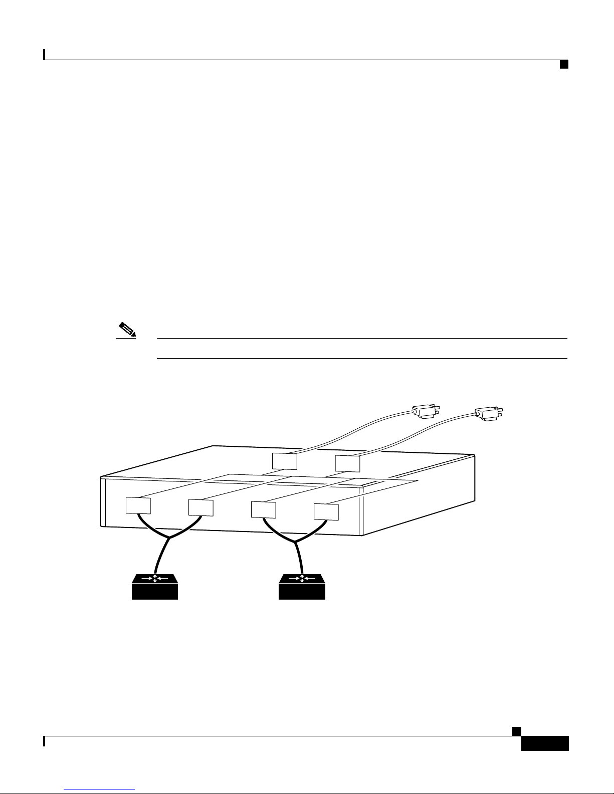
Redundant with Reboot
By using a mode of operation called redundant with reboot, you can connect more
hubs and switches to the Cisco RPS and thereby extend its capacity or provide
additional redundancy. Redundancy with reboot works for the following devices
only: FastHub 400 series hubs, Catalyst 1900 series and Catalyst 2820 switches,
and Catalyst 2900 series and Catalyst 3500 series XL switches. However, this
configuration is not generally recommended, because a power supply failure will
cause an interruption while the hub or switch reboots.
The redundant-with-reboot configuration is shown in Figure 1-3, where a
straight-through one-to-one cable connects an external switch or hub to the
Cisco RPS while the device is powered by its own internal power supply (the
device AC power plug is connected).
Figure 1-3 Redundant-With-Reboot Configuration
Chapter 1 Overview
Cisco RPS
DC output
DC
DC
AC power cords
AC power strip
DC
AC
AC input
AC
12052
DC
External devices
150W or less
In this configuration, one Cisco RPS can support four devices. The Cisco RPS and
the external device internal power supply are both connected.
Cisco Redundant Power System Hardware Installation Guide
1-6
OL-3654-01
Page 29

Chapter 1 Overview
Note If you use this configuration, always power up the external device before
Supported Devices and Configurations
powering up the Cisco RPS to ensure correct operation. If the Cisco RPS powers
up first, the LEDs might not indicate the actual state.
After power up, a sense circuit in the Cisco RPS reads that the device has its AC
power connected and shuts the Cisco RPS output off, preventing competition
between the power supplies.
Normally, the external device internal power supply always provides power. If the
internal power system of the hub or switch fails, the device powers down briefly
(for approximately 30 seconds) until the Cisco RPS begins supplying power.
When the device comes back up, the Cisco RPS is the main power source.
In this configuration, if the Cisco RPS fails or is disconnected, the external device
does not power cycle, because its internal power supply has not been disturbed.
When both the Cisco RPS and internal power supply are powered, the RPS LED
on the external device blinks green, and the LED on the Cisco RPS front panel is
off because the Cisco RPS is not supplying power.
Despite 30 seconds of downtime that occur when using redundancy with reboot,
this configuration does provide additional redundancy and extends the capacity of
the Cisco RPS.
Note Cisco recommends that you do not use the redundant-with-reboot configuration
with the hub or switch connected to both the Cisco RPS and to the AC power plug,
because of the 30-second reboot and downtime. If you do use the
redundant-with-reboot configuration, always power up the external device before
you power up the Cisco RPS to ensure correct operation. When the Cisco RPS
powers up first, the LEDs might not indicate the actual state.
Quasi- and Fully Redundant Mixed Configuration
You can mix quasi-redundant and fully redundant configurations for supported
devices. For example, two devices can be in quasi-redundant mode while one is
in fully redundant mode (see Figure 1-4).
OL-3654-01
Cisco Redundant Power System Hardware Installation Guide
1-7
Page 30

Front and Rear Panel Descriptions
Figure 1-4 Mixed Configuration
Chapter 1 Overview
AC input
Cisco RPS
DC
DC
AC
DC
AC
DC
DC output
Quasi-RedundantFully redundant
Front and Rear Panel Descriptions
The LEDs on the Cisco RPS front panel show the Cisco RPS operational status.
Figure 1-5 shows the front panel of the Cisco RPS.
11681
Figure 1-5 Cisco RPS Front Panel
Cisco Redundant Power System Hardware Installation Guide
1-8
DC STATUS
12
3
4
FAN
TEM
P
H9588
OL-3654-01
Page 31

Chapter 1 Overview
The Cisco RPS rear panel has two AC power connectors, each with an on/off
switch, and four DC connectors for connecting to devices. Figure 1-6 shows the
rear panel. See Chapter 3, “Connection Requirements,” for information about
required cables and connectors.
Figure 1-6 Cisco RPS Rear Panel
Front and Rear Panel Descriptions
100-200 V~ 50/60 Hz
10-5 A 1000 W
LEDs
AC INPUT 1
AC INPUT 2
100-200 V~ 50/60 Hz
10-5 A 1000 W
DC OUTPUT 1
DC OUTPUT 2
DC OUTPUT 3
DC OUTPUT 4
H9589
The LEDs on the front panel of the Cisco RPS display the current operating
condition of the Cisco RPS:
• AC STATUS LEDs—Two on the left side of the front panel.
• DC STATUS LEDs—Four on the center of the front panel.
• FAN and TEMP LEDs—Both on the right side of the front panel.
When the Cisco RPS is working properly, all LEDs on its front panel are solid
green.
Note Some external devices also include LEDs that show the operating condition of the
Cisco RPS. Refer to the installation guide that accompanied the device for
detailed information about the device LEDs.
OL-3654-01
Cisco Redundant Power System Hardware Installation Guide
1-9
Page 32

Front and Rear Panel Descriptions
Figure 1-7 shows the Cisco RPS front panel LEDs, and Table 1-2 explains the
meaning of the colors.
Figure 1-7 Cisco RPS LEDs
DC STATUS
12
3
Chapter 1 Overview
FA
4
N
TEM
P
H9629
AC status LEDs
DC status LEDs
Fan and temp LEDs
Table 1-2 LED Descriptions
LED Name Color/State Description
AC STATUS Off AC power is not being supplied to the Cisco RPS, or it is switched off.
Amber AC power is being supplied to the Cisco RPS, but the designated
AC-input power module has failed.
Green The AC-input power module is on and operating correctly.
DC STATUS
Note The DC status LEDs are numbered to correspond to the
DC-output connectors on the Cisco RPS rear panel.
Off
The DC output is powered down at the external device, AC power is not
being supplied to the Cisco RPS, or there is no output cable attached to
the DC output module.
Cisco Redundant Power System Hardware Installation Guide
1-10
OL-3654-01
Page 33

Chapter 1 Overview
Table 1-2 LED Descriptions (continued)
LED Name Color/State Description
Amber The DC output power module has failed.
Note The DC status LED is amber for 10 to 15 seconds after the DC
output power module has been connected and the external device
has been powered up before it turns green to indicate correct
operation.
Note If you are using a Cisco RPS with a revision level lower than Z3
with a Catalyst 3508G or a Catalyst 3548 XL switch, the switch
RPS LED and the RPS DC LED of the connector for the switch
might display amber (normally indicating a Cisco RPS
malfunction) even when the Cisco RPS is functioning properly.
The LEDs display correctly for Cisco RPS revision level Z3 or
later revision. The label on the bottom of the Cisco RPS shows
the revision.
Safety Recommendations
Green The DC output power module is on and operating correctly.
FAN Off AC power is not being supplied to the Cisco RPS.
Amber One or more cooling fans has failed.
Green All cooling fans are functioning correctly.
TEMP Off AC power is not being supplied to the Cisco RPS.
Amber The Cisco RPS internal temperature is exceeding the operating range.
Green The Cisco RPS internal temperature is within the operating range.
Safety Recommendations
Follow these guidelines to guarantee general safety:
• Keep the chassis area clear and dust-free during and after installation.
• Keep tools and chassis components away from walk areas where you or others
could fall over them.
• Do not wear loose clothing that could get caught in the chassis. Fasten your
tie or scarf and roll up your sleeves.
OL-3654-01
Cisco Redundant Power System Hardware Installation Guide
1-11
Page 34

Safety Recommendations
• Wear safety glasses when working under conditions that might be hazardous
to your eyes.
• Do not perform any action that creates a hazard to people or makes the
equipment unsafe.
Safety Warnings
Safety warnings appear throughout this guide in procedures that, if performed
incorrectly, might harm you. A warning symbol precedes each warning statement.
(For information on safety warnings and translations, see the “Notes, Cautions,
and Warnings” section on page xi.)
Safety with Electricity
Chapter 1 Overview
Warning
Warning
Warning
Read the installation instructions before you connect the system to its power
source. To see translations of the warnings that appear in this publication, refer
to the Regulatory Compliance and Safety Information document that
accompanied this device.
The device is designed to work with TN power systems. To see translations of
the warnings that appear in this publication, refer to the Regulatory Compliance
and Safety Information document that accompanied this device.
Before working on equipment that is connected to power lines, remove jewelry
(including rings, necklaces, and watches). Metal objects will heat up when
connected to power and ground and can cause serious burns or weld the metal
object to the terminals. To see translations of the warnings that appear in this
publication, refer to the Regulatory Compliance and Safety Information
document that accompanied this device.
Cisco Redundant Power System Hardware Installation Guide
1-12
OL-3654-01
Page 35

Chapter 1 Overview
Safety Recommendations
Warning
Warning
Warning
This product relies on the building’s installation for short-circuit (overcurrent)
protection. Make sure that a fuse or circuit breaker is no larger than 120 VAC,
15A U.S. (240 VAC, 10A international) is used on the phase conductors (all
current-carrying conductors). To see translations of the warnings that appear in
this publication, refer to the Regulatory Compliance and Safety Information
document that accompanied this device.
This equipment is intended to be grounded. Make sure that the host is
connected to earth ground during normal use. To see translations of the
warnings that appear in this publication, refer to the Regulatory Compliance
and Safety Information document that accompanied this device.
Ultimate disposal of this product should be handled according to all national
laws and regulations. To see translations of the warnings that appear in this
publication, refer to the Regulatory Compliance and Safety Information
document that accompanied this device.
Follow these guidelines when working on equipment powered by electricity:
OL-3654-01
• Locate the emergency power-off switch in the room in which you are
working. Then, if an electrical accident occurs, you can quickly shut the
power off.
• Look carefully for possible hazards in your work area, such as moist floors,
ungrounded power extension cables, and missing safety grounds.
• If an electrical accident occurs, proceed as follows:
–
Use caution; do not become a victim yourself.
–
Turn off power to the Cisco RPS.
–
If possible, send another person to get medical aid. Otherwise, determine
the condition of the victim and then call for help.
–
Determine if the person needs rescue breathing or external cardiac
compressions; then take appropriate action.
Cisco Redundant Power System Hardware Installation Guide
1-13
Page 36

Safety Recommendations
Chapter 1 Overview
Cisco Redundant Power System Hardware Installation Guide
1-14
OL-3654-01
Page 37

CHAPTER
Installing the Cisco RPS
You can set the Cisco RPS chassis on a desktop or install it in a rack.
2
Warning
Warning
Warning
Warning
Only trained and qualified personnel should be allowed to install or replace
this equipment. To see translations of the warnings that appear in this
publication, refer to the Regulatory Compliance and Safety Information
document that accompanied this device.
Do not work on the system or connect or disconnect cables during periods of
lightning activity. To see translations of the warnings that appear in this
publication, refer to the Regulatory Compliance and Safety Information
document that accompanied this device.
Before opening the chassis, disconnect the telephone-network cables to
avoid contact with telephone-network voltages. To see translations of the
warnings that appear in this publication, refer to the Regulatory Compliance
and Safety Information document that accompanied this device.
This equipment is intended to be grounded. Ensure that the host is connected to
earth ground during normal use. To see translations of the warnings that appear
in this publication, refer to the Regulatory Compliance and Safety Information
document that accompanied this device.
OL-3654-01
Cisco Redundant Power System Hardware Installation Guide
2-1
Page 38

Chapter 2 Installing the Cisco RPS
Warning
Warning
Never defeat the ground conductor or operate the equipment in the absence of
a suitably installed ground conductor. Contact the appropriate electrical
inspection authority or an electrician if you are uncertain that suitable
grounding is available. To see translations of the warnings that appear in this
publication, refer to the Regulatory Compliance and Safety Information
document that accompanied this device.
When installing the unit, the ground connection must always be made first and
disconnected last. To see translations of the warnings that appear in this
publication, refer to the Regulatory Compliance and Safety Information
document that accompanied this device.
• Do not work alone if potentially hazardous conditions exist.
• Never assume that power is disconnected from a circuit. Always check.
The Cisco RPS location is extremely important for proper operation. Equipment
placed too close together, inadequate ventilation, and inaccessible panels can
cause malfunctions and shutdowns and can make maintenance difficult. The
following information will help you to plan the location of the chassis.
2-2
• Plan for access to both the front and rear panels of the Cisco RPS.
• Make sure that the room where the Cisco RPS operates has adequate
ventilation. Remember that electrical equipment generates heat. Ambient air
temperature might not cool equipment to acceptable operating temperatures
without adequate ventilation. (See Table A-1 on page A-1.)
Use the procedure that best meets your needs:
• “Setting the Cisco RPS on a Desktop” section on page 2-3
• “Rack-Mounting the Cisco RPS” section on page 2-3
Cisco Redundant Power System Hardware Installation Guide
OL-3654-01
Page 39

Chapter 2 Installing the Cisco RPS
Setting the Cisco RPS on a Desktop
Setting the Cisco RPS on a Desktop
Warning
Warning
Do not stack the chassis on any other equipment. If the chassis falls, it can
cause severe bodily injury and equipment damage. To see translations of the
warnings that appear in this publication, refer to the Regulatory Compliance
and Safety Information document that accompanied this device.
This unit is intended for installation in restricted access areas. A restricted
access area is where access can only be gained by service personnel through
the use of a special tool, lock and key, or other means of security and is
controlled by the authority responsible for the location. To see translations of
the warnings that appear in this publication, refer to the Regulatory Compliance
and Safety Information document that accompanied this device.
To install your chassis on a desktop, perform the following steps:
Step 1 Unpack the Cisco RPS.
Step 2 Attach the rubber feet from the accessory kit in the round recesses on the chassis
bottom.
Step 3 Set the Cisco RPS chassis on an appropriate desktop.
Step 4 Plug in the Cisco RPS, and turn power on.
Note If you have questions or need assistance, see the “Obtaining Documentation”
section on page xviii.
Rack-Mounting the Cisco RPS
This sections explains how to rack-mount the Cisco RPS in 19-, 23-, 24-inch, or
telco equipment racks. Read the following information before rack-mounting
your chassis.
Cisco Redundant Power System Hardware Installation Guide
OL-3654-01
2-3
Page 40

Rack-Mounting the Cisco RPS
Planning Your Rack-Mount Installation
Chapter 2 Installing the Cisco RPS
Warning
To prevent bodily injury when mounting or servicing this unit in a rack, you must
take special precautions to ensure that the system remains stable. The
following guidelines are provided to ensure your safety. To see translations of
the warnings that appear in this publication, refer to the Regulatory Compliance
and Safety Information document that accompanied this device.
• This unit should be mounted at the bottom of the rack if it is the only unit in
the rack.
• When mounting this unit in a partially filled rack, load the rack from the
bottom to the top with the heaviest component at the bottom of the rack.
• If the rack is provided with stabilizing devices, install the stabilizers before
mounting or servicing the unit in the rack.
The following information will help you plan your equipment rack installation:
• Enclosed racks must have adequate ventilation. Make sure that the rack is not
congested, because each unit generates heat. Heat generated by equipment
near the bottom of the rack can be drawn upward into the intake ports of the
equipment above. An enclosed rack should have louvered sides and a fan to
provide cooling air.
2-4
• When mounting a chassis in an open rack, make sure that the rack frame does
not block the intake or exhaust ports. If the chassis is installed on slides,
check the position of the chassis when it is seated in the rack.
• Baffles can isolate exhaust air from intake air, which also helps to draw
cooling air through the chassis. The best placement of the baffles depends on
the airflow patterns in the rack, which can be found by experimenting with
different configurations.
• When equipment installed in a rack (particularly in an enclosed rack) fails,
try operating the equipment by itself, if possible. Power off other equipment
in the rack and in adjacent racks to allow the unit under test a maximum of
cooling air and clean power.
• Install the Cisco RPS and the external device to which it will connect in
adjacent shelves in a rack.
Cisco Redundant Power System Hardware Installation Guide
OL-3654-01
Page 41

Chapter 2 Installing the Cisco RPS
Tools and Equipment Required
You need the following tools and equipment to rack-mount the Cisco RPS:
• Number 2 Phillips screwdriver (not included)
• Screws for attaching the Cisco RPS to the rack (not included)
• Rack-mount brackets (see Figure 2-1 and Figure 2-2):
–
One set of 19-inch brackets (ACS-3640RM-19=) ships with the
Cisco RPS.
–
Order 23- or 24-inch brackets (ACS-3640RM-24=), as needed.
–
Order telco brackets (AS52/3RM-TELCO-19=), as needed.
Identifying Rack-Mount Brackets
Rack-Mounting the Cisco RPS
Figure 2-1 shows the 19-, 23-, and 24-inch brackets; Figure 2-2 shows the telco
bracket.
Figure 2-1 19-, 23-, and 24-Inch Rack-Mount Brackets
Use with 23-inch rack
Use with 24-inch rack
H9695
Bracket for 19-inch rack
Bracket for 23- and 24-inch rack
OL-3654-01
Cisco Redundant Power System Hardware Installation Guide
2-5
Page 42

Rack-Mounting the Cisco RPS
Figure 2-2 Telco Bracket
Attaching Brackets
To install the Cisco RPS in a rack, attach the brackets in one of the following
ways:
Chapter 2 Installing the Cisco RPS
10254
• With the Cisco RPS front panel forward (see Figure 2-3).
• With the Cisco RPS rear panel forward (see Figure 2-4).
• In a center-mount telco rack (see Figure 2-5).
Note Although Figure 2-3 and Figure 2-4 show 19-inch brackets, the procedure is the
same for 23-inch, 24-inch, and telco brackets.
Cisco Redundant Power System Hardware Installation Guide
2-6
OL-3654-01
Page 43

Chapter 2 Installing the Cisco RPS
D
C
S
T
A
T
U
S
12
3
4
Figure 2-3 Bracket Installation—Front Panel Forward
Note: The second bracket attaches to the other side of the chassis.
Rack-Mounting the Cisco RPS
H9696
F
A
N
T
E
M
P
Figure 2-4 Bracket Installation—Rear Panel Forward
D
C O
U
TPU
T 2
Note: The second bracket attaches to the other side of the chassis.
DC
O
U
TPU
T 3
DC
O
U
TPU
T 4
H9697
OL-3654-01
Cisco Redundant Power System Hardware Installation Guide
2-7
Page 44

Rack-Mounting the Cisco RPS
Figure 2-5 Telco Bracket Installation—Rear Panel Forward
D
Note: The second bracket attaches to the other side of the chassis.
The brackets can also be installed with the Cisco RPS front panel forward.
Chapter 2 Installing the Cisco RPS
11540
C
O
U
T
P
U
T
3
D
C
O
U
T
P
U
T
4
Mounting the Chassis in a Rack
After the brackets are secured to the chassis, use your own screws to attach the
chassis to the rack, as shown in Figure 2-6.
Figure 2-6 Attaching the Chassis to a Rack—Rear Panel Forward
D
C
O
U
T
P
U
T
3
Note: The second bracket attaches to the rack at the other side of the chassis.
D
C
O
U
T
P
U
T
4
H9699
Cisco Redundant Power System Hardware Installation Guide
2-8
OL-3654-01
Page 45

CHAPTER
3
Connection Requirements
This chapter describes the equipment required to connect the Cisco RPS to
external devices. The Cisco RPS includes two fully redundant AC input power
modules and four DC output power modules for connection to external devices.
The Cisco RPS supports a quasi-redundant configuration for all devices, fully
redundant configuration for the referenced Cisco routers and concentrator, and
redundant-with-reboot configurations for the referenced hubs and switches.
However, the redundant-with-reboot configuration is not recommended because a
power supply failure will cause an interruption while the hub or switch reboots.
For an explanation of power source configurations, refer to Chapter 1,
“Overview.”
OL-3654-01
Caution The Cisco RPS AC input power modules are power-factor-corrected to comply
with certain International Electrotechnical Commission (IEC) standards. Do not
connect the Cisco RPS to an uninterruptible power supply (UPS) that has not been
tested and designed for power-factor-corrected power systems. Do not connect the
Cisco RPS to a ferro-resonant transformer. If you do either of these things, you
could damage the Cisco RPS.
This chapter contains the following sections:
• Tools and Equipment Required, page 3-2
• Cabling Options, page 3-2
• Ordering Cables, page 3-3
• Upgrade Kit with Power Adapter Plate for Routers and Concentrators,
page 3-6
Cisco Redundant Power System Hardware Installation Guide
3-1
Page 46

Tools and Equipment Required
Tools and Equipment Required
You might need to order the following equipment:
• One-to-one 22-pin to 8-pin cable—Needed for Cisco 2500 series routers and
Cisco MC3810 multiservice concentrators
• Y- ca b le —Needed for fully redundant power configurations
• Upgrade kit—Needed for routers that originally came with AC or DC power
supplies (Cisco 2500 and Cisco 2600 series routers; Cisco 3620, Cisco 3640,
and Cisco 3725 routers; Cisco 4000 series routers; and the Cisco MC3810
multiservice concentrator)
Cabling Options
Chapter 3 Connection Requirements
The external devices have different configuration and cabling options outlined
below and are discussed in detail under the referenced section of this manual:
• The Cisco 1516M hub (HP 10BASE-T Hub-16M) only supports a one-to-one
cable for quasi-redundant configuration. This hub does not support
connection of its AC power cable for redundancy with reboot or the use of the
Y-cable for full redundancy.
• FastHub 400 series 100BASE-T hubs support:
–
One-to-one cable for quasi-redundancy
–
One-to-one cable with the switch AC power cable connected for
redundancy with reboot (not recommended)
Refer to the “Connecting Hubs” section on page 4-2 for illustrations and
procedures.
• Catalyst 1900 series switches, Catalyst 2820 switches, Catalyst 2900 series
XL switches, and Catalyst 3500 series XL switches support:
–
One-to-one cable for quasi-redundancy
–
One-to-one cable with the switch AC power cable connected for
redundancy with reboot (not recommended)
See the “Connecting Switches” section on page 4-6 for illustrations and
procedures.
Cisco Redundant Power System Hardware Installation Guide
3-2
OL-3654-01
Page 47

Chapter 3 Connection Requirements
• Cisco 2500 and Cisco 2600 series routers; Cisco 3620, Cisco 3640, and
Cisco 3725 routers; Cisco 4000 series routers; and the Cisco MC3810
multiservice concentrator support:
–
–
Ordering Cables
The Cisco RPS ships in either of the following configurations:
• With cables (Cisco RPS number PWR600-AC-RPS-CAB)—Includes four
one-to-one (22-pin to 18-pin) cables for connecting to hubs and switches or
for quasi-redundant support for Cisco 2600 series routers; Cisco 3620,
Cisco 3640, and Cisco 3725 routers; and Cisco 4000 series routers.
Ordering Cables
One-to-one cable for quasi-redundancy
Two-to-one Y-cable for full redundancy
Refer to the “Connecting Routers and the Cisco MC3810 Concentrator”
section on page 4-13 for illustrations and procedures.
• Without cables (Cisco RPS number PWR600-AC-RPS-NCAB)—Cables
must be ordered separately:
–
One-to-one (22-pin to 18-pin) cables for connecting to hubs and switches
or for quasi-redundant support for Cisco 2600 series routers; Cisco 3620,
Cisco 3640, and Cisco 3725 routers; and Cisco 4000 series routers
–
One-to-one (22-pin to 8-pin) cables for quasi-redundant support for
Cisco 2500 series routers and Cisco MC3810 multiservice concentrators
–
Two-to-one Y cables (22-pin to 18-pin, or 22-pin to 8-pin) for fully
redundant support for routers or concentrators only
Note The fully redundant configuration is supported only for routers, not
for hubs or switches.
Figure 3-1 and Figure 3-2 show the cables you can order, and Table 3-1 includes
cable descriptions and lists the corresponding product order numbers. For
ordering information, contact 800 553-6387, 408 526-7208, or
cs-rep@cisco.com. See also the “Obtaining Documentation” section on
page xviii.
OL-3654-01
Cisco Redundant Power System Hardware Installation Guide
3-3
Page 48

Ordering Cables
Figure 3-1 Two-to-One Y-Shaped Cable
Load unit
8 or 18 pins
Chapter 3 Connection Requirements
Cisco RPS side
22 pins
Product number External device
CAB-RPSY-2208 Cisco 2500 series routers and Cisco MC3810 multiservice concentrators
CAB-RPSY-2218
Cisco 2600 series routers, Cisco 3620, Cisco 3640, and Cisco 3725
routers, and Cisco 4000 series routers
Figure 3-2 One-to-One Cable
Load unit
8 or 18 pins
Product number External device
CAB-RPS-2208 Cisco 2500 series routers and Cisco MC3810 multiservice concentrator
CAB-RPS-2218
All others
RPS side
22 pins
11538
11539
Cisco Redundant Power System Hardware Installation Guide
3-4
OL-3654-01
Page 49

Chapter 3 Connection Requirements
Table 3-1 Cable Order Numbers
Ordering Cables
Redundancy
Configuration For Use With Cable Description
Quasi-redundant Cisco 1516M hub (HP 10BASE-T
Hub-16M), FastHub 400 series hubs,
Catalyst 1900 series and Catalyst 2820
One-to-one cable,
22-pin to 18-pin,
4ft (1.22m)
1
switches, Catalyst 2900 series and
Catalyst 3500 series XL switches,
Cisco 2600 series routers, Cisco 3620,
Cisco 3640, and Cisco 3725 routers, and
Cisco 4000 series routers
Cisco 2500 series routers and access
servers and Cisco MC3810 multiservice
concentrators
Fully redundant Cisco 2600 series routers, Cisco 3620,
Cisco 3640, and Cisco 3725 routers, and
Cisco 4000 series routers
Cisco 2500 series routers and access
servers and Cisco MC3810 multiservice
concentrators
One-to-one cable,
22-pin to 8-pin,
4ft (1.22m)
1
Two-to-one cable,
22-pin to 18-pin,
4ft (1.22m)
1
Two-to-one cable,
22-pin to 8-pin,
4ft (1.22m)
1
Cable Order
Number
CAB-RPS-2218=
CAB-RPS-2208=
CAB-RPSY-2218=
CAB-RPSY-2208=
Redundant with
reboot
2
FastHub 400 series hubs, Catalyst 1900
series and Catalyst 2820 switches, and
Catalyst 2900 series and Catalyst 3500
One-to-one cable,
22-pin to 18-pin,
4ft (1.22m)
1
CAB-RPS-2218=
series XL switches
1. The cables come in only one length. Custom cable-lengths are not available. Excessive voltage drop and marginal or failed
operation can occur with cables of different lengths. Use of cables other than the ones listed can cause damage to the
Cisco RPS or external device.
2. This configuration is not recommended due to the 30-second reboot and downtime.
Cisco Redundant Power System Hardware Installation Guide
OL-3654-01
3-5
Page 50

Chapter 3 Connection Requirements
Upgrade Kit with Power Adapter Plate for Routers and Concentrators
Upgrade Kit with Power Adapter Plate for Routers
and Concentrators
External devices operated with the Cisco RPS must have a Cisco RPS connector.
Cisco 2600 series routers, Cisco 3620, Cisco 3640, and Cisco 3725 routers, and
Cisco 4000 series routers, and the Cisco MC3810 concentrator do not
automatically ship with an RPS connector.
Note The FastHub 400 series hubs, Cisco 1516M hub (HP 10ASE-T Hub-16M),
Catalyst 1900 series and Catalyst 2820 switches, and Catalyst 2900 series and
Catalyst 3500 series XL switches ship with an RPS connector and do not require
a power adapter plate.
If you did not order your router or concentrator with a Cisco RPS connector
installed, you must order a power adapter plate that provides compatibility and
must install the plate in place of your existing power supply.
If you need to order a power adapter plate for your router or concentrator, see
Table 3-2, which lists adapter plates and corresponding product order numbers.
Contact Cisco Customer Service at 800 553-6387, 408 526-7208, or
cs-rep@cisco.com for ordering information. (See also the “Obtaining
Documentation” section on page xviii.)
Table 3-2 Power Adapter Plate Product Numbers
Description Product Number
Cisco 2500 series, Cisco MC3810 adapter plate ACS-2500RPS=
Cisco 2600 series adapter plate ACS-2600RPS=
Cisco 3620 adapter plate ACS-3620RPS=
Cisco 3640 adapter plate ACS-3640RPS=
Cisco 3725 adapter plate ??
Cisco 4000 series adapter plate ACS-4000RPS=
Device-specific instructions for installing the RPS adapter plate are shipped with
the plate and are also available on Cisco.com at http://www.cisco.com.
Cisco Redundant Power System Hardware Installation Guide
3-6
OL-3654-01
Page 51

CHAPTER
Connecting the Cisco RPS
This chapter provides instructions on connecting your external device to the
Cisco RPS. The chapter is divided into the following major sections:
• Power Considerations, page 4-1
• Connecting Hubs, page 4-2
• Connecting Switches, page 4-6
• Connecting Routers and the Cisco MC3810 Concentrator, page 4-13
4
Power Considerations
Before connecting to external devices, read the power warnings below. We
recommend that you disconnect all power before beginning.
Note If you want to connect an additional external device to a Cisco RPS that is already
powered up, you can do so without interrupting power to the Cisco RPS or any
other connected external devices. Be sure to connect your cable to the Cisco RPS
first and then to the external device. However, in a redundant-with-reboot
configuration, to ensure proper operation, you must power up the switch or hub
before powering up the Cisco RPS. Therefore, always connect the switch to AC
power before you connect it to the Cisco RPS. Failure to follow the proper
power-up sequence can result in incorrect LED displays.
Cisco Redundant Power System Hardware Installation Guide
OL-3654-01
4-1
Page 52

Connecting Hubs
Chapter 4 Connecting the Cisco RPS
Warning
Warning
Warning
Attach only the Cisco RPS (model PWR600-AC-RPS) to the RPS receptacle. To
see translations of the warnings that appear in this publication, refer to the
Regulatory Compliance and Safety Information document that accompanied this
device.
Before performing any of the following procedures, ensure that power is
removed from the DC circuit. To ensure that all power is OFF, locate the circuit
breaker on the panel board that services the DC circuit, switch the circuit
breaker to the OFF position, and tape the switch handle of the circuit breaker in
the OFF position. To see translations of the warnings that appear in this
publication, refer to the Regulatory Compliance and Safety Information
document that accompanied this device.
Before working on a system that has an on/off switch, turn OFF the power and
unplug the power cord. To see translations of the warnings that appear in this
publication, refer to the Regulatory Compliance and Safety Information
document that accompanied this device.
Warning
This unit might have more than one power cord. To reduce the risk of electric
shock, disconnect the two power supply cords before servicing the unit. To see
translations of the warnings that appear in this publication, refer to the
Regulatory Compliance and Safety Information document that accompanied this
device.
Connecting Hubs
This section provides illustrations and cabling information for connecting the
Cisco RPS to the following hubs:
• Cisco 1516M hub (HP 10BASE-T Hub-16M) (Figure 4-1)
• FastHub 400 series hubs (Figure 4-2)
Cisco Redundant Power System Hardware Installation Guide
4-2
OL-3654-01
Page 53

Chapter 4 Connecting the Cisco RPS
Note The Cisco RPS can also be used with the older FastHub 100, 200, and 300 series
hubs.
All hubs can use the one-to-one cable configuration for quasi-redundancy. The
FastHub 400 series also supports the option of connecting the AC power cord for
redundancy with reboot, although this configuration is not recommended. The use of
a Y-cable for full redundancy is not supported.
The HP 10BASE-T Hub-16M does not support redundancy with reboot and does not
support use of the Y-cable for full redundancy.
To connect hubs to the Cisco RPS, perform these steps:
Step 1 Disconnect the AC power cord on the hub.
Step 2 Connect one end of the one-to-one cable to the Cisco RPS connector on the hub
rear panel. (For connector locations, see Figure 4-1 and Figure 4-2.)
Connecting Hubs
Step 3 Connect the other end of the cable to a Cisco RPS rear-panel connector as shown
in Figure 4-3.
Figure 4-1 Cisco 1516M Hub (HP 10BASE-T Hub-16M) Rear Panel
RS-232
AC power
connector
Cisco RPS
connector
Serial port
11537
Reset
switch
OL-3654-01
Cisco Redundant Power System Hardware Installation Guide
4-3
Page 54

Connecting Hubs
Figure 4-2 FastHub 400 Rear Panel
R
A
T
I
N
G
1
0
0
-
1
2
7
/
2
0
0
-
2
4
0
V
~
2
A
/
1
A
5
0
/
6
0
H
z
CONSOLE
DOWN
Chapter 4 Connecting the Cisco RPS
D
C
IN
P
U
T
S
F
O
R
R
E
M
O
T
E
P
O
W
E
R
S
U
P
P
L
UP
+
S
P
5
V
E
C
IF
I
E
@
6
A
DC INPUT
Y
D
IN
M
A
N
U
A
L
, +
1
2
V
@
1
A
MEDIA MODULE
28729
AC power
connector
Cisco RPS
connector
Figure 4-3 Connecting the One-to-One Cable to the Cisco RPS
AC INPUT 1
100-200 V~ 50/60 Hz
10-5 A 1000 W
AC INPUT 2
100-200 V~ 50/60 Hz
10-5 A 1000 W
DC OUTPUT 1
DC OUTPUT 2
DC OUTPUT 3
All ass
DC OUTPUT 4
29090
Step 4
On the Cisco RPS rear panel, connect an AC power cable to either or both of the
power connectors. Use the cable locks on the Cisco RPS to lock the cables in
place. (See Figure 4-4.)
Cisco Redundant Power System Hardware Installation Guide
4-4
OL-3654-01
Page 55

Chapter 4 Connecting the Cisco RPS
Figure 4-4 Connecting the AC Power Cables to the Cisco RPS
Connecting Hubs
29092
Cable locks
Step 5 Connect the other end of the Cisco RPS AC power cable into an AC power outlet.
Step 6 If you are using the redundant-with-reboot configuration (not recommended),
power up the switch by connecting the hub AC power cord to an AC power outlet.
Note If you use the redundant-with-reboot configuration, always power up the
hub before you power up the Cisco RPS.
Step 7 Power up the Cisco RPS. There is one power switch for each AC input power
module. Make sure that the power switch is in the ON (|) position for each AC
power module used. (See Figure 4-5.)
OL-3654-01
Cisco Redundant Power System Hardware Installation Guide
4-5
Page 56

Connecting Switches
Chapter 4 Connecting the Cisco RPS
Figure 4-5 Powering Up the Cisco RPS
Power switch
29091
The Cisco RPS provides power in 10 to 15 seconds. The Cisco RPS is working
properly when all its front-panel LEDs are solid green. If the external device does not
power up, refer to Chapter 5, “Troubleshooting the Cisco RPS.”
Connecting Switches
The Catalyst 1900 series and Catalyst 2820 series switches and the Catalyst 2900
series and Catalyst 3500 series XL switches can use:
• One-to-one cable for quasi-redundancy
or
• One-to-one cable with the switch AC power cable connected for redundancy
with reboot (not recommended)
To connect switches to the Cisco RPS, perform these steps:
Step 1 Disconnect the AC power cord on the switch.
Cisco Redundant Power System Hardware Installation Guide
4-6
OL-3654-01
Page 57

Chapter 4 Connecting the Cisco RPS
Step 2 Connect one end of the one-to-one cable to the Cisco RPS connector on the switch
rear panel. (For connector locations, see Figure 4-6 through Figure 4-12.)
Figure 4-6 Catalyst 1900 Switch Rear Panel
Connecting Switches
R
A
T
IN
G
1
0
0
-
1
2
7
V
~
@
0
.6
A
2
0
0
-
2
4
0
V
~
@
0
.
3
A
5
0
-
6
0
H
z
D
C
I
N
P
U
T
F
O
R
R
E
M
O
T
E
P
O
W
E
R
S
U
P
P
L
Y
S
P
E
C
IF
I
E
D
I
N
M
A
N
U
A
L
.
+
5
V
@
6
A
+
1
2
V
@
1
A
C
O
N
S
O
L
E
A
U
I
29087
AC power
connector
Cisco RPS
connector
Figure 4-7 Catalyst 2820 Switch Rear Panel
AC power
connector
R
A
T
IN
G
1
0
0
-
1
2
7
/2
0
0
-
2
4
0
V
~
2
.0
A
/1
.0
A
5
0
/6
0
H
z
D
C
P
O
W
IN
M
+
1
C
O
N
S
O
L
E
P
O
R
T
Cisco RPS
connector
28730
IN
P
U
T
S
F
O
R
R
E
M
O
T
E
E
R
S
U
P
P
L
Y
S
P
E
C
IF
IE
D
A
N
U
A
L
. +
5
V
@
1
4
A
,
2
V
@
1
A
, -1
2
V
@
1
A
D
C
IN
P
U
T
S
A
U
I
OL-3654-01
Cisco Redundant Power System Hardware Installation Guide
4-7
Page 58

Chapter 4 Connecting the Cisco RPS
Connecting Switches
Figure 4-8 Catalyst 2912 XL, Catalyst 2924 XL, and Catalyst 2924C XL Switch Rear Panel
D
C
I
N
P
U
T
S
F
O
R
R
E
M
O
T
E
P
O
W
E
R
S
U
P
P
L
Y
S
P
E
C
I
F
IE
D
IN
M
A
N
U
A
L
5
V
@
9
A
,
+
1
2
V
@
0
.5
A
C
O
N
S
O
L
E
AC power
connector
+
R
A
T
IN
G
1
0
0
-
1
2
7
/2
~
0
0
-
2
4
0
V
1
.0
A
/O
.
5
A
5
0
-
8
0
H
Z
Cisco RPS
connector
Figure 4-9 Catalyst 2912M XL and Catalyst 2924M XL Switch Rear Panel
R
A
T
IN
G
1
0
0
-1
2
0
/2
0
0
-2
4
2
.0
A
/1
.0
A
5
0
-6
D
C
IN
P
U
T
S
F
O
R
R
E
M
O
T
E
P
O
W
E
R
S
U
P
P
L
Y
S
P
E
C
IF
IE
D
IN
M
A
N
U
A
L
+
5
C
O
N
S
O
L
E
V
.
@
2
4
A
, +
1
2
V
@
1
.0
A
D
C
IN
P
U
T
0
28731
~
0
V
H
Z
28732
Cisco Redundant Power System Hardware Installation Guide
4-8
Cisco RPS
connector
AC power
connector
OL-3654-01
Page 59

Chapter 4 Connecting the Cisco RPS
28734
Figure 4-10 Catalyst 3508G XL Switch Rear Panel
1
0
0
1
.0
A
Connecting Switches
29088
DC INPU
R
A
T
IN
G
-
1
2
7
/2
0
0
-2
4
0
V
~
/0
.5
A
5
0
-
6
0
H
Z
C
O
N
S
O
LE
TS FOR REM
O
TE POW
ER SUP
PL
SPEC
IFIED IN M
D
C
IN
P
U
T
Y
AN
U
AL. +3.3
V***@14A,
+12V***@3A
AC power
connector
Cisco RPS
connector
Figure 4-11 Catalyst 3512 XL and Catalyst 3524 XL Switch Rear Panel
DC INPUTS FO
1
0
0
1
.0
A
AC power
connector
R
A
T
I
N
G
-
1
2
7
/
2
0
0
-
2
4
0
V
~
/
0
.
5
A
5
0
-
6
0
H
Z
C
O
N
S
O
L
E
R RE
M
O
TE
PO
W
ER
SU
PPLY
SPEC
IFIED IN MA
N
UAL.
+5V @
24A, +12V @
.5A
Cisco RPS
connector
Figure 4-12 Catalyst 3548 XL Switch Rear Panel
28733
R
A
T
IN
1
0
0
-
1
2
7
/2
0
0
1
.0
A
/0
.5
A
5
AC power
connector
OL-3654-01
DC INPUTS FO
R REM
OTE PO
W
ER
G
-2
4
0
V
~
0
-6
0
H
Z
SPECIFIED
D
C
IN
IN M
ANUAL. +3.3V***@
P
U
T
+12V***@
SUPPLY
14A,
3A
C
O
N
S
O
L
E
Cisco RPS
connector
Cisco Redundant Power System Hardware Installation Guide
4-9
Page 60

Connecting Switches
Step 3 Connect the other end of the one-to-one cable to the Cisco RPS rear-panel
connector, as shown in Figure 4-13.
Figure 4-13 Connecting the One-to-One Cable to the Cisco RPS
Chapter 4 Connecting the Cisco RPS
AC INPUT 1
100-200 V~ 50/60 Hz
10-5 A 1000 W
Step 4
AC INPUT 2
100-200 V~ 50/60 Hz
10-5 A 1000 W
DC OUTPUT 1
DC OUTPUT 2
DC OUTPUT 3
DC OUTPUT 4
On the Cisco RPS rear panel, connect an AC power cable to either or both of the
power connectors. Use the cable locks on the Cisco RPS to lock the cables in
place. (See Figure 4-14.)
29090
Cisco Redundant Power System Hardware Installation Guide
4-10
OL-3654-01
Page 61

Chapter 4 Connecting the Cisco RPS
Figure 4-14 Connecting the AC Power Cables to the Cisco RPS
Connecting Switches
29092
Cable locks
Step 5
Connect the other end of the Cisco RPS AC power cable into an AC power outlet.
Step 6 If you are using the redundant-with-reboot configuration (not recommended),
power up the switch by connecting the switch AC power cord into an AC power
outlet.
Note If you use the redundant-with-reboot configuration, always power up the
switch before you power up the Cisco RPS.
Step 7 Power up the Cisco RPS. There is one power switch for each of the AC input
power modules. Make sure that the power switch for each connected AC cable is
in the ON (|) position. (See Figure 4-15.)
OL-3654-01
Cisco Redundant Power System Hardware Installation Guide
4-11
Page 62

Connecting Switches
Chapter 4 Connecting the Cisco RPS
Figure 4-15 Powering Up the Cisco RPS
Power switch
29091
The Cisco RPS provides power in 10 to 15 seconds. The Cisco RPS is working
properly when all its front panel LEDs are solid green. If the external device does not
power up, refer to Chapter 5, “Troubleshooting the Cisco RPS.”
Note If you are using a Cisco RPS with a revision level lower than Z3 with a Catalyst
3508G or a Catalyst 3548 XL switch, the switch RPS LED and the RPS DC LED
might display amber (normally indicating Cisco RPS malfunction) even when the
Cisco RPS is functioning properly. The LEDs display correctly for Cisco RPS
revision level Z3 or later revision. The label on the bottom of the Cisco RPS
shows the revision level.
Cisco Redundant Power System Hardware Installation Guide
4-12
OL-3654-01
Page 63

Chapter 4 Connecting the Cisco RPS
Connecting Routers and the Cisco MC3810 Concentrator
Connecting Routers and the Cisco MC3810
Concentrator
This section provides illustrations and cabling information for connecting the
Cisco RPS to Cisco 2500 series and Cisco 2600 series routers; Cisco 3620, Cisco
3640, and Cisco 3725 routers; Cisco 4000 series routers and Cisco MC3810
multiservice concentrators. All these devices use:
• One-to-one cable for quasi-redundancy
or
• Two-to-one Y-cable for full redundancy
Note If you did not order your router or concentrator with a Cisco RPS connector
installed, you must order a power adapter plate and must install it in place of your
existing power supply.
If you need to order a power adapter plate, see Table 3-1 on page 3-5, which lists
adapter plates and corresponding product order numbers. Contact Cisco Customer
Service at 800 553-6387 or 408 526-7209 for ordering information. (See also the
“Obtaining Documentation” section on page xviii.)
Device-specific instructions for installing the Cisco RPS adapter plate are shipped
with the plate and are also available on Cisco.com at http://www.cisco.com.
Note Cisco IOS Software Release 11.2(7)P or later release is required when using the
Cisco RPS with Cisco 3620, Cisco 3640, or Cisco 3725 routers.
To connect a router or multiservice concentrator to the Cisco RPS, perform the
following steps:
Step 1 Power off the router or concentrator by pressing the power switch to the OFF (O)
position.
Step 2 Connect one end of the one-to-one cable or Y-cable to the Cisco RPS connector
on the rear panel of the router or concentrator, as shown in Figure 4-16 through
Figure 4-21.
OL-3654-01
Cisco Redundant Power System Hardware Installation Guide
4-13
Page 64

Connecting Routers and the Cisco MC3810 Concentrator
Figure 4-16 Cisco 2500 Series Router Rear Panel
T
O
K
E
N
R
IN
G
Figure 4-17 Cisco 2600 Series Router Rear Panel
On/off
switch
Chapter 4 Connecting the Cisco RPS
Input: 100-240VAC
Freq: 50/60 Hz
Current: 1.2-0.6A
Watts: 40W
Cisco RPS
connector
H9425
S
E
R
I
A
L
1
S
E
R
I
A
L
0
W
I
C
O
N
N
S
E
E
M
A
N
C
C
O
N
N
2
A
/
S
C
O
N
U
A
L
B
E
F
O
R
E
I
N
S
T
A
L
L
A
L
I
N
K
N
T
I
O
N
S
E
E
M
A
N
U
A
L
B
E
F
O
R
E
I
N
L
I
N
K
E
T
H
E
R
N
E
T
0
A
C
T
C
O
N
Figure 4-18 Cisco 3620 Router Rear Panel
2
E
W
1
2
W
B
1
NT1
B
R
B
2
S
E
E
M
A
N
U
A
L
B
E
E
T
H
E
R
N
E
T
1
1
I
N
T
1
F
O
R
E
I
N
S
T
A
L
L
A
T
I
O
N
ACT
LNK
ACT
LNK
E
T
H
E
R
N
E
T
0
2E
W
O
ACT
W
1
D
O
N
O
T IN
S
2W
S
E
R
IA
L
A
U
I
E
N
TA
LL
W
A
N
IN
TE
R
FA
C
E
C
A
R
D
S W
IT
H
P
O
W
E
R
A
P
P
L
IE
D
ACT
LNK
ACT
E
T
H
E
E
T
R
H
N
1
E
T 1
LNK
E
T
H
E
R
N
E
S
E
R
I
A
L
1
C
S
E
R
I
A
L
0
W
I
C
C
O
N
N
2
A
/
S
S
T
A
L
L
A
T
I
O
N
W
0
S
O
L
E
A
U
X
On/off switch
ACT
T
0
is
c
o
2
6
1
1
S
E
R
IA
L
A
U
I
E
N
0
Cisco RPS
connector
D
C
I
N
P
U
T
F
O
R
U
S
E
W
I
T
+
5
V
–
–
–
1
4
A
,
+
1
2
V
–
–
–
5
A
On/off
switch
Cisco
RPS
connector
11751
12276
H
C
I
S
C
O
R
P
S
,
-
1
2
V
–
–
–
3
A
Cisco Redundant Power System Hardware Installation Guide
4-14
OL-3654-01
Page 65

Chapter 4 Connecting the Cisco RPS
Figure 4-19 Cisco 3640 Router Rear Panel
On/off switch
3
2
E
W
1
2
W
E
T
H
E
R
1
NT1
B
1
B
2
S
E
E
M
A
N
U
A
N
E
T
1
B
R
I
N
T
L
B
1
E
F
O
R
E
IN
S
T
A
L
L
A
T
IO
N
LNK
ACT
LNK
ACT
E
T
H
E
R
N
E
T
0
2E
W
O
W
1
ACT
SE
R
DO NOT INSTALL WAN INTERFACE
2
W
IA
CARDS WITH POWER APPLIED
L
S
T
P
A
U
I
E
N
ETHERNET 1
LNK
ACT
ACT
LNK
E
T
H
E
R
N
ACT
E
T
0
Figure 4-20 Cisco 4000 Series Router Rear Panel
2
S
E
R
IA
L
A
U
I
E
N
INPUT 100-240VAC 50/60HZ 3.0-1.5 AMPS
Connecting Routers and the Cisco MC3810 Concentrator
Cisco RPS
connector
12277
OL-3654-01
On/off
switch
Cisco RPS
connector
Cisco Redundant Power System Hardware Installation Guide
11750
4-15
Page 66

Connecting Routers and the Cisco MC3810 Concentrator
Figure 4-21 Cisco MC3810 Multiservice Concentrator Rear Panel
A
V
M
1
2
3
4
5
6
ETHERNET 0
SERIAL 0
SERIAL 1
CONSOLE AUX
On/off switch
Chapter 4 Connecting the Cisco RPS
12212
P
O
W
E
R
Cisco RPS
connector
Step 3
Connect the other end of the one-to-one or Y-cable to the rear panel connector on
the Cisco RPS, as shown in Figure 4-22 and Figure 4-23.
Figure 4-22 Connecting a One-to-One Cable for Quasi-Redundant Power
AC INPUT 1
100-200 V~ 50/60 Hz
10-5 A 1000 W
AC INPUT 2
100-200 V~ 50/60 Hz
10-5 A 1000 W
DC OUTPUT 1
DC OUTPUT 2
DC OUTPUT 3
DC OUTPUT 4
29090
Cisco Redundant Power System Hardware Installation Guide
4-16
OL-3654-01
Page 67

Chapter 4 Connecting the Cisco RPS
Connecting Routers and the Cisco MC3810 Concentrator
Figure 4-23 Connecting a Two-to-One Y-Cable for Fully Redundant Power
AC INPUT 1
100-200 V~ 50/60 Hz
10-5 A 1000 W
AC INPUT 2
100-200 V~ 50/60 Hz
10-5 A 1000 W
DC OUTPUT 1
DC OUTPUT 2
DC OUTPUT 3
DC OUTPUT 4
29089
Step 4 On the rear panel of the Cisco RPS, connect an AC power cable to either or both
of the power connectors. Use the cable locks on the Cisco RPS to lock the cables
in place. (See Figure 4-24.)
Figure 4-24 Connecting the AC Power Cables to the Cisco RPS
OL-3654-01
29092
Cable locks
Cisco Redundant Power System Hardware Installation Guide
4-17
Page 68

Connecting Routers and the Cisco MC3810 Concentrator
Step 5 Connect the other end of the Cisco RPS AC power cable into a grounded AC
power outlet.
Step 6 Power up the Cisco RPS. There is one power switch for each of the AC input
power modules. Make sure that the power switch for each connected AC cable is
in the ON (|) position. (See Figure 4-25.)
Figure 4-25 Powering Up the Cisco RPS
Power switch
Chapter 4 Connecting the Cisco RPS
29091
Step 7 Power on the router or concentrator by pressing the power switch to the ON (|)
position.
The Cisco RPS is on and provides power to the external device in 10 to 15 seconds.
The Cisco RPS is working properly when all its front-panel LEDs are solid green. If
the external device does not power up, see Chapter 5, “Troubleshooting the
Cisco RPS.”
Cisco Redundant Power System Hardware Installation Guide
4-18
OL-3654-01
Page 69

CHAPTER
5
Troubleshooting the Cisco RPS
The key to troubleshooting is to isolate the problem to a specific subsystem. Start
by reading the LEDs on the front panel of the Cisco RPS and any error messages
displayed on the external device console. If you are unable to resolve the problem,
refer to the “Getting Technical Support” section on page 5-14.
This chapter contains the following sections:
• Reading the LEDs, page 5-1
• Displaying Status, page 5-5
• Error Messages on Cisco 2600 Series and Cisco 3620, Cisco 3640, and
Cisco 3725 Routers, page 5-6
• Replacing an External Device, page 5-13
• Getting Technical Support, page 5-14
Reading the LEDs
The LEDs on the front panel of the Cisco RPS (see Figure 5-1) display the current
operating condition of the Cisco RPS. Refer to Table 1-2 on page 1-10 for the
meaning of various LED colors. When the Cisco RPS is working properly, the
LEDs are solid green. When there is a problem with any component, the related
LED is amber.
OL-3654-01
Cisco Redundant Power System Hardware Installation Guide
5-1
Page 70

Reading the LEDs
Note Some external devices also have LEDs that show the operating condition of the
Cisco RPS. Refer to the installation guide that accompanied the device for
detailed information about the LEDs.
Table 5-1 lists symptoms indicating a problem, along with possible causes and
suggested corrective actions.
Figure 5-1 Cisco RPS LEDs
Chapter 5 Troubleshooting the CiscoRPS
AC status LEDs
DC STATUS
12
3
4
DC status LEDs
FAN
TE
M
P
Fan and temp LEDs
H9629
Cisco Redundant Power System Hardware Installation Guide
5-2
OL-3654-01
Page 71

Chapter 5 Troubleshooting the Cisco RPS
Table 5-1 Symptoms and Recommended Responses
Symptom Description of Error Corrective Action
Reading the LEDs
DC LED 1, 2, 3, or 4 is
amber.
Note The DC LED is
always amber
for 10 to 15
seconds after
the DC output
module has
been connected
and the
external device
has been
powered on.
The cable connected to an
internal DC output module is
loose, or the internal DC output
module has failed.
Note If you are using a
Cisco RPS with a
revision level lower
than Z3 with a Catalyst
3508G or a Catalyst
3548 XL switch, the
switch RPS LED and
the RPS DC LED of the
connector to the switch
might display amber
(normally indicating a
Cisco RPS
malfunction) even when
the Cisco RPS is
functioning properly.
The LEDs display
correctly for Cisco RPS
revision level Z3 or
later. The label on the
bottom of the
Cisco RPS shows the
revision level.
The DC status LED numbers correspond
to the DC output connectors on the
Cisco RPS rear panel. Check the LEDs to
determine which connector is affected.
Note The following steps power down
the external device if it is not
already down.
1. Disconnect the corresponding output
cable from the external device. The
amber light goes off.
2. Ensure that the other end of the output
cable is securely connected to the
Cisco RPS and that the connector is
fully seated.
3. Reconnect the output cable to the
external device.
4. Ensure that the connector is fully
seated and is attached securely to the
external device.
5. Wait 15 seconds. The LED is amber
for 15 seconds and then is green.
If the failure persists, the DC output
module has failed, and the Cisco RPS
needs to be replaced. If there is an unused
DC output module, try switching to it as a
temporary solution.
OL-3654-01
Cisco Redundant Power System Hardware Installation Guide
5-3
Page 72

Chapter 5 Troubleshooting the CiscoRPS
Reading the LEDs
Table 5-1 Symptoms and Recommended Responses (continued)
Symptom Description of Error Corrective Action
AC 1 or 2 LED is
amber or off.
One of the following has
occurred:
• Power has been turned off
to one of the wall outlets
into which the specific
Cisco RPS AC power cord
is plugged.
• One of the power cords has
been disconnected from
either the Cisco RPS or the
wall outlet.
• One of the AC modules has
been turned off.
• One of the AC modules has
failed.
FAN LED is amber. One of the fans has failed. The
remaining fans switch to full
speed to keep the Cisco RPS
cool.
Look at the AC LEDs to determine which
AC module is reporting the error.
1. Ensure that the AC module power
switch is on and that the power cord is
locked in place.
2. Ensure that the power cord is securely
connected to a wall outlet and that the
wall outlet is receiving power.
If the failure persists, one of the AC output
modules has failed, and the Cisco RPS
needs to be replaced. Contact your Cisco
representative or reseller.
The Cisco RPS continues to operate with a
single fan failure. To correct the failure,
replace the Cisco RPS. Contact your Cisco
representative or reseller.
TEMP LED is amber. The temperature inside the
Cisco RPS is too high.
Cisco Redundant Power System Hardware Installation Guide
5-4
1. Ensure that the temperature of the
room where the Cisco RPS is located
is not above 40
o
C and adjust
temperature setting if necessary.
2. Ensure that the front and rear panels
of the Cisco RPS are clear of any
obstructions.
If the LED remains amber, replace the
Cisco RPS. Contact your Cisco
representative or reseller.
OL-3654-01
Page 73

Chapter 5 Troubleshooting the Cisco RPS
Displaying Status
Cisco IOS Release 11.2(7)P and later releases support status messages for
Cisco 3620 and Cisco 3640 series routers using the Cisco RPS. Cisco IOS
Release 11.3(2) and later releases support status messages for Cisco 2600 series
routers using the Cisco RPS. Cisco IOS Release 12.2(8)T, Cisco IOS Release
12.2(11)YT, and later releases support status messages for Cisco 3725 series
routers using the Cisco RPS.
Status messages are not supported for the FastHub 400 series hubs, Cisco 1516M
hubs (HP 10BASE-T Hub-16M), Catalyst 1900 series and Catalyst 2820
switches, Catalyst 2900 series and Catalyst 3500 series XL switches, Cisco 2500
series and Cisco 4000 series routers, and Cisco MC3810 multiservice
concentrators.
The show env command (available in Cisco IOS Releases 11.2(7) and later
releases) provides an environmental status of the Cisco RPS. A sample display
follows:
Displaying Status
router# show env
Power Supply:
Redundant Power supply is present.
Thermal status is normal.
AC status is normal.
DC status is normal.
Board Temperature:
Warning: Board overtemperature condition detected.
Caution If the Cisco RPS gets too hot, it shuts down to prevent damage to its components.
If thermal shutdown occurs because the cooling system failed or the ambient
temperature rose above normal operating limits, a thermal warning displays on the
router console, and an SNMP trap is sent before shutdown.
OL-3654-01
Cisco Redundant Power System Hardware Installation Guide
5-5
Page 74

Chapter 5 Troubleshooting the CiscoRPS
Error Messages on Cisco 2600 Series and Cisco 3620, Cisco 3640, and Cisco 3725 Routers
Error Messages on Cisco 2600 Series and Cisco 3620,
Cisco 3640, and Cisco 3725 Routers
When a Cisco RPS status failure is detected while connected to Cisco 2600 series,
Cisco 3620, Cisco 3640, and Cisco 3725 routers, Cisco IOS software receives an
interrupt and displays the error messages on the router console. The following
sections describe the console messages and SNMP traps issued following each
error condition and after corrective action.
DC Failure
LED status:
DC LED 1, 2, 3, or 4 is amber.
Note The DC LED is always amber for 10 to 15 seconds after the DC output module
has been connected and the external device has been powered on.
Console Error Message:
• When an external device console monitor screen displays the Cisco IOS
software prompt (
System detected Redundant Power Supply DC FAIL condition.
The Cisco IOS software checks the condition once every 30 seconds. If the
condition still exists, the error message reappears.
• When an external device console monitor screen displays the ROMMON
prompt (
*** System Environmental Interrupt ***
WARNING: REDUNDANT POWER SUPPLY DC FAIL BIT IS ASSERTED.
Error Description:
The cable connected to one of the internal DC output modules is loose, or one of
the internal DC output modules in the Cisco RPS has failed.
rommon#>)
routername> or routername#)
Cisco Redundant Power System Hardware Installation Guide
5-6
OL-3654-01
Page 75

Chapter 5 Troubleshooting the Cisco RPS
Error Messages on Cisco 2600 Series and Cisco 3620, Cisco3640, and Cisco 3725 Routers
Note Cisco 2600 series, Cisco 3620, Cisco 3640, and Cisco 3725 routers report the
failure of any of the Cisco RPS DC output modules, including the DC output
modules to which they are not directly connected.
SNMP Trap Issued Upon Error:
ciscoEnvMonRedundantSupplyNotification is generated.
The varbinds included are ciscoEnvMonSupplyStatusDescr and
ciscoEnvMonSupplyState.
The value of ciscoEnvMonSupplyState is a warning.
How to Correct Error:
Check the DC LEDs on the front panel of the Cisco RPS to determine which cable
is loose or if the module has failed, and try the corrective actions described in
Table 5-1.
AC Failure
Console Message Issued Upon Correction of Error:
• When an external device console monitor screen displays the Cisco IOS
software prompt (
Redundant Power Supply DC condition is now normal.
• When an external device console monitor screen displays the ROMMON
prompt (
SNMP Trap Issued Upon Correction of Error:
rommon#>), no console message is issued when the error is corrected.
routername> or routername#)
ciscoEnvMonRedundantSupplyNotification is generated.
The varbinds included are ciscoEnvMonSupplyStatusDescr and
ciscoEnvMonSupplyState.
The value of ciscoEnvMonSupplyState is a warning.
LED status:
AC LED 1 or 2 is amber or off.
OL-3654-01
Cisco Redundant Power System Hardware Installation Guide
5-7
Page 76

Chapter 5 Troubleshooting the CiscoRPS
Error Messages on Cisco 2600 Series and Cisco 3620, Cisco 3640, and Cisco 3725 Routers
Console Error Message:
• When an external device console monitor screen displays the Cisco IOS
software prompt (
System detected Redundant Power Supply AC FAIL condition.
routername> or routername#)
The Cisco IOS software checks the condition every 30 seconds. If the
condition still exists, the error message reappears.
• When an external device console monitor screen displays the ROMMON
prompt (
*** System Environmental Interrupt ***
WARNING: REDUNDANT POWER SUPPLY AC FAIL BIT IS ASSERTED.
rommon#>)
Error Description:
One of the AC modules has been turned off or has been disconnected or has failed.
See Table 5-1 for details. The Cisco IOS software checks the condition every 30
seconds. If the condition still exists, the error message reappears.
SNMP Trap Issued Upon Error:
ciscoEnvMonRedundantSupplyNotification is generated.
The varbinds included are ciscoEnvMonSupplyStatusDescr and
ciscoEnvMonSupplyState.
The value of ciscoEnvMonSupplyState is a warning.
How to Correct Error:
Check the AC LEDs on the Cisco RPS to determine which AC module is reporting
the error, and try the corrective actions described in Table 5-1.
Console Message Issued Upon Correction of Error:
• When an external device console monitor screen displays the Cisco IOS
software prompt (
Redundant Power Supply AC condition is now normal.
• When an external device console monitor screen displays the ROMMON
prompt (
rommon#>), no console message is issued when the error is corrected.
routername> or routername#)
Cisco Redundant Power System Hardware Installation Guide
5-8
OL-3654-01
Page 77

Chapter 5 Troubleshooting the Cisco RPS
SNMP Trap Issued Upon Correction of Error:
ciscoEnvMonRedundantSupplyNotification is generated.
The varbinds included are ciscoEnvMonSupplyStatusDescr and
ciscoEnvMonSupplyState.
The value of ciscoEnvMonSupplyState is a warning.
Fan Failure
LED status:
FAN LED is amber.
Console Error Message:
• When an external device console screen displays the Cisco IOS software
prompt (
Error Messages on Cisco 2600 Series and Cisco 3620, Cisco3640, and Cisco 3725 Routers
routername> or routername#)
System detected Redundant Power Supply THERMAL FAIL condition.
The Cisco IOS software checks the condition once every 30 seconds. If the
condition still exists, the error message reappears.
• When an external device console monitor screen displays the ROMMON
prompt (
*** System Environmental Interrupt ***
WARNING: REDUNDANT POWER SUPPLY THERMAL BIT IS ASSERTED.
rommon#>)
Error Description:
One of the Cisco RPS fans has failed. The remaining fans switch to full speed to
keep the Cisco RPS cool.
SNMP Trap Issued Upon Error:
ciscoEnvMonRedundantSupplyNotification is generated.
The varbinds included are ciscoEnvMonSupplyStatusDescr and
ciscoEnvMonSupplyState.
The value of ciscoEnvMonSupplyState is a warning.
OL-3654-01
Cisco Redundant Power System Hardware Installation Guide
5-9
Page 78

Chapter 5 Troubleshooting the CiscoRPS
Error Messages on Cisco 2600 Series and Cisco 3620, Cisco 3640, and Cisco 3725 Routers
How to Correct Error:
The Cisco RPS continues to operate with a single fan failure, but to correct the
failure, replace the Cisco RPS.
Console Message Issued Upon Correction of Error:
• When an external device console monitor screen displays the Cisco IOS
software prompt (
Redundant Power Supply THERMAL condition is now normal.
• When an external device console screen displays the ROMMON prompt
(
rommon#>), no console message is issued when the error is corrected.
routername> or routername#)
SNMP Trap Issued Upon Correction of Error:
ciscoEnvMonRedundantSupplyNotification is generated.
The varbinds included are ciscoEnvMonSupplyStatusDescr and
ciscoEnvMonSupplyState.
The value of ciscoEnvMonSupplyState is a warning.
Temperature Error
LED status:
TEMP LED is amber.
Console Error Message:
• When an external device console monitor screen displays the Cisco IOS
software prompt (
System detected Redundant Power Supply THERMAL FAIL condition.
The Cisco IOS software checks the condition once every 30 seconds. If the
condition still exists, the error message reappears.
• When an external device console screen displays the ROMMON prompt
(
rommon#>)
*** System Environmental Interrupt ***
WARNING: REDUNDANT POWER SUPPLY THERMAL BIT IS ASSERTED.
routername> or routername#)
Cisco Redundant Power System Hardware Installation Guide
5-10
OL-3654-01
Page 79

Chapter 5 Troubleshooting the Cisco RPS
Error Messages on Cisco 2600 Series and Cisco 3620, Cisco3640, and Cisco 3725 Routers
Error Description:
The temperature inside the Cisco RPS is too hot.
SNMP Trap Issued Upon Error:
ciscoEnvMonRedundantSupplyNotification is generated.
The varbinds included are ciscoEnvMonSupplyStatusDescr and
ciscoEnvMonSupplyState.
The value of ciscoEnvMonSupplyState is a warning.
How to Correct Error:
• Check the temperature of the room where the Cisco RPS is located, and
correct the temperature setting if it is above 40
• Check the front and rear panels of the Cisco RPS to make sure they are clear
o
C.
of any obstructions.
• If the error message persists, replace the Cisco RPS.
Console Message Issued Upon Correction of Error:
• When an external device console screen displays the Cisco IOS software
prompt (routername> or routername#)
Redundant Power Supply THERMAL condition is now normal
• When an external device console screen displays the ROMMON prompt
(
rommon#>), no console message is issued when the error is corrected.
SNMP Trap Issued Upon Correction of Error:
ciscoEnvMonRedundantSupplyNotification is generated.
The varbinds included are ciscoEnvMonSupplyStatusDescr and
ciscoEnvMonSupplyState.
The value of ciscoEnvMonSupplyState is a warning.
OL-3654-01
Cisco Redundant Power System Hardware Installation Guide
5-11
Page 80

Error Messages on Cisco 2600 Series and Cisco 3620, Cisco 3640, and Cisco 3725 Routers
Multiple Errors
LED status:
Two or more of the Cisco RPS LEDs are amber.
Console Error Message:
• When an external device console screen displays the Cisco IOS software
prompt (
There is more than one failure with the redundant power systems;
please resolve problems immediately.
The Cisco IOS software checks the condition once every 30 seconds. If the
condition still exists, the error message reappears.
routername> or routername#)
Chapter 5 Troubleshooting the CiscoRPS
Note It is not a multiple failure when two or more DC output modules have failed.
• When an external device console screen displays the ROMMON prompt
(
rommon#>),
The message will vary depending on the mix of failures.
Error Description:
The Cisco RPS has two or more failures of any of the previous types.
SNMP Trap Issued Upon Error:
ciscoEnvMonRedundantSupplyNotification is generated.
The varbinds included are ciscoEnvMonSupplyStatusDescr and
ciscoEnvMonSupplyState.
The value of ciscoEnvMonSupplyState is a warning.
How to Correct Error:
Look at the LEDs on the Cisco RPS front panel to determine the types of failures
that have occurred. Go to the section in Table 5-1 describing each failure type for
instructions on how to correct it.
If the error message persists, replace the Cisco RPS.
Cisco Redundant Power System Hardware Installation Guide
5-12
OL-3654-01
Page 81

Chapter 5 Troubleshooting the Cisco RPS
Console Message Issued Upon Correction of Error:
• When an external device console screen displays the Cisco IOS software
prompt (
Redundant power system is now normal.
• When an external device console screen displays the ROMMON prompt
(
rommon#>), no console message is issued when the error is corrected.
SNMP Trap Issued Upon Correction of Error:
ciscoEnvMonRedundantSupplyNotification is generated.
The varbinds included are ciscoEnvMonSupplyStatusDescr and
ciscoEnvMonSupplyState.
The value of ciscoEnvMonSupplyState is a warning.
Replacing an External Device
routername> or routername#)
Replacing an External Device
If an external device (hub, switch, router, or concentrator) that is receiving power
from the Cisco RPS fails, you can replace it without powering down the
Cisco RPS or interrupting power to any other external devices. Follow these steps
to replace a failed external device that is connected to the Cisco RPS:
Note Do not power down the Cisco RPS.
Step 1 Power down the external device.
a. If the external device is a router or concentrator, press the on/off switch to the
OFF position.
b. If the external device is a hub or switch configured in redundant-with-reboot
mode, disconnect the AC power cord. (If the hub or switch is in
quasi-redundant mode, Step 2 powers down the switch.)
Step 2 Disconnect the Cisco RPS connector from the external device. Make sure to leave
the AC input power cable connected to the Cisco RPS.
Step 3 Replace the failed external device.
OL-3654-01
Cisco Redundant Power System Hardware Installation Guide
5-13
Page 82

Getting Technical Support
Step 4 If the external device is a hub or switch in redundant-with-reboot mode, connect
the external device AC power cord to an AC power outlet to turn on power.
Note If you use this configuration, you must always power up the external
Step 5 Reconnect the new external device to the Cisco RPS power cable.
Step 6 If the external device is a router or concentrator, press the device on/off switch to
the ON (|) position to power up the device.
The new external device powers up in 10 to 15 seconds.
Chapter 5 Troubleshooting the CiscoRPS
device before you connect the Cisco RPS cable connector to the switch.
Getting Technical Support
If you cannot locate the source of the problem, refer to the information packet
publication that shipped with your Cisco RPS for information about how to
contact technical support. Before you contact technical support, have the
following information ready:
• Chassis serial number
• Maintenance agreement, license, or warranty information
• Date you received the Cisco RPS
• Brief description of the problem
• Brief explanation of the steps you have taken to isolate the problem
If the product is under warranty or is covered by a Cisco maintenance contract,
contact Cisco’s Technical Assistance Center (TAC) at 800 533-2447, 408
526-7209, tac@cisco.com, or http://www.cisco.com.
Cisco Redundant Power System Hardware Installation Guide
5-14
OL-3654-01
Page 83

APPENDIX
Technical Specifications
The technical specifications for the Cisco RPS are listed in Table A-1.
Table A-1 Specifications
Environmental Ranges
Operating temperature 32 to 104°F (0 to 40°C)
Storage temperature –4 to 149°F (–20 to 65°C)
Operating humidity 10 to 85% (noncondensing)
Storage humidity 5 to 95% (noncondensing)
A
OL-3654-01
Operating altitude Up to 10,000 ft (3,000 m)
Storage altitude Up to 15,000 ft (4,570 m)
Normal operating noise level 48 dBa
Power Requirements
Nominal input voltage
Current
Frequency
Absolute maximum input
Output voltage/maximum current +5VDC at 24A,
Output power 150W per module (maximum)
Cisco Redundant Power System Hardware Installation Guide
100 to 240 VAC autoranging
10A maximum
50 to 60 Hz
1000W
+12VDC at 5A,
–12VDC at 3 A
A-1
Page 84

Appendix A Technical Specifications
Table A-1 Specifications (continued)
Physical Dimensions
Weight 27.25 lb (12.36 kg)
Dimensions (H x W x D) 3.44 x 17.5 x 16 in.
(8.73 x 44.45 x 40.64 cm)
For agency approval and compliance information, refer to the Regulatory
Compliance and Safety Information document that accompanied the Cisco RPS.
Cisco Redundant Power System Hardware Installation Guide
A-2
OL-3654-01
Page 85

INDEX
A
AC frequency A-1
AC input voltage A-1
AC STATUS LED 1-10
altitude A-1
B
brackets, rack-mount 2-5 to 2-8
C
cable locks 4-5, 4-11, 4-17
cables
Cisco.com xviii
Cisco 1516M hub, connecting 4-2
Cisco 2500 series routers, connecting 4-13
Cisco 2600 series routers, connecting 4-13
Cisco 3620 and Cisco 3640 routers,
connecting
4-13
Cisco 3725 routers, connecting 4-13
Cisco 4000 series routers, connecting 4-13
Cisco MC3810 multiservice concentrators,
connecting
4-13
connecting to hubs 4-2
connecting to routers and concentrators 4-13
connecting to switches 4-6
current, input A-1
AC power, connecting
4-10, 4-17
one-to-one, connecting 4-10, 4-16
two-to-one (Y), connecting, 4-17
types required 3-2
Catalyst 1900 series switches, connecting 4-6
Catalyst 2820 switches, connecting 4-6
Catalyst 2900 series XL switches,
connecting
4-6
Catalyst 3500 series XL switches,
connecting
4-6
Caution symbol, meaning of xi
OL-3654-01
D
DC STATUS LED 1-10
Documentation CD-ROM ix
E
equipment racks 2-4
error messages, reading on Cisco 2600 series
and Cisco 3620, Cisco 3640, and Cisco
3725 routers
Cisco Redundant Power System Hardware Installation Guide
5-6
IN-1
Page 86

Index
external devices, connecting
Catalyst 1900 series switches
Catalyst 2820 series switches 4-6
Catalyst 2900 series XL switches 4-6
Catalyst 3500 series XL switches 4-6
Cisco 1516M hub 4-2
Cisco 2500 series routers 4-13
Cisco 2600 series routers 4-13
Cisco 3620 and Cisco 3640 routers 4-13
Cisco 3725 routers 4-13
Cisco 4000 series routers 4-13
Cisco MC3810 multiservice
concentrators
FastHub 400 series hubs 4-2
HP 10BASE-T Hub-16M 4-2
4-13
4-6
I
installation 2-3
L
LEDs
all green
description and corrective action 5-3
on external devices 1-9
reading 5-1
RPS front panel 1-9
location, planning 2-2
1-9, 5-1
external devices, replacing 5-13
F
FAN LED 1-11
FastHub 300 series hubs, connecting 4-2
features, RPS 1-1
front panel, Cisco RPS 1-8
fully redundant configuration 1-5
H
HP 10BASE-T Hub-16M, connecting 4-2
humidity A-1
M
maintenance contract 5-14
N
noise level A-1
Note symbol, meaning of xi
O
output power per Cisco RPS module A-1
output voltage from Cisco RPS A-1
Cisco Redundant Power System Hardware Installation Guide
IN-2
OL-3654-01
Page 87

Index
P
power adapter plate
ordering
3-6
product numbers 3-6
when required 4-13
power configurations 1-4 to 1-6
power specifications A-1
Q
quasi-redundant configuration 1-4
R
Cisco 3640 router 4-15
Cisco 4000 series router 4-15
Cisco MC3810 multiservice
concentrator
4-16
Cisco RPS 1-9
FastHub 400 series hub 4-4
HP 10BASE-T Hub-16M 4-3
redundant-with-reboot configuration ?? to 1-6
S
safety
power warning
recommendations 1-11
warnings 1-12
4-2
rack-mount brackets 2-5
rack-mounting the chassis 2-3
rear panel
Catalyst 1900 series switch
4-7
Catalyst 2820 series switch 4-7
Catalyst 2912, 2924, 2924C XL switches 4-8
Catalyst 2912M and 2924M XL switches 4-8
Catalyst 3508G XL switch 4-9
Catalyst 3512 and 3524 XL switch 4-9
Catalyst 3548 XL switch 4-9
Cisco 1516M hub 4-3
Cisco 2500 series router 4-14
Cisco 2600 series router 4-14
Cisco 3620 router 4-14
with electricity 1-12
specifications A-2
status, displaying 5-5
Symbols
Cautions
xi
Notes xi
Warnings xi
T
Technical Assistance Center (TAC) xix, 5-14
telco brackets, product number 2-5
temperature, operating A-1
TEMP LED 1-11
OL-3654-01
Cisco Redundant Power System Hardware Installation Guide
IN-3
Page 88

Index
U
upgrade kits 3-2, 3-6
V
voltage input A-1
W
warnings, installation 2-1
Y
Y-cables 3-2
Cisco Redundant Power System Hardware Installation Guide
IN-4
OL-3654-01
 Loading...