

Page 1

Cisco − ILMI Address Registration Problems: %LANE−3−NOREGILMI
Table of Contents
ILMI Address Registration Problems: %LANE−3−NOREGILMI..............................................................1
Document ID: 10450................................................................................................................................1
Introduction..........................................................................................................................................................1
Prerequisites.........................................................................................................................................................1
Requirements..........................................................................................................................................1
Components Used...................................................................................................................................1
Conventions............................................................................................................................................2
Associated Error Message....................................................................................................................................2
Configure.............................................................................................................................................................2
Network Diagram....................................................................................................................................2
Configurations........................................................................................................................................3
Checking ILMI.....................................................................................................................................................3
ILMI Status.............................................................................................................................................3
When ILMI is Disabled on the Switch Interface....................................................................................4
Access List Configuration Problems or ILMI Community Configured as Read−Only.........................5
Known Caveats.......................................................................................................................................6
If the Switch Knows the NSAP Address.............................................................................................................6
When the NSAP Address Is Configured Statically on the Switch..........................................................6
When the NSAP Address Is Registered via ILMI by Another Device...................................................7
Configuration Problems.....................................................................................................................................10
Related Information...........................................................................................................................................11
i
Page 2

ILMI Address Registration Problems:
%LANE−3−NOREGILMI
Document ID: 10450
Introduction
Prerequisites
Requirements
Components Used
Conventions
Associated Error Message
Configure
Network Diagram
Configurations
Checking ILMI
ILMI Status
When ILMI is Disabled on the Switch Interface
Access List Configuration Problems or ILMI Community Configured as Read−Only
Known Caveats
If the Switch Knows the NSAP Address
When the NSAP Address Is Configured Statically on the Switch
When the NSAP Address Is Registered via ILMI by Another Device
Configuration Problems
Related Information
Introduction
This document explains how to troubleshoot Interim Local Management Interface (ILMI) address registration
problems on Cisco devices when using LAN emulation (LANE).
The ILMI protocol uses Simple Network Management Protocol (SNMP) format packets across the
User−Network Interface (UNI) to access an ILMI Management Information Base (MIB) associated with the
link within each node. The ILMI protocol facilitates network−wide auto configuration by allowing adjacent
nodes to determine each other's characteristics. Examples of these characteristics are the size of each other's
connection space, the type of signaling used (UNI or NNI), type of link (public or private) and hooks for
network management autodiscovery.
ILMI is also used for address registration.
Prerequisites
Requirements
There are no specific requirements for this document.
Components Used
This document is not restricted to specific software and hardware versions.
Cisco − ILMI Address Registration Problems: %LANE−3−NOREGILMI
Page 3
Conventions
For more information on document conventions, refer to the Cisco Technical Tips Conventions.
Associated Error Message
Address resolution problems are usually associated with the following error message:
%LANE−3−NOREGILMI: [chars] [chars] cannot register [ATM address] with ILMI
For example:
%LANE−3−NOREGILMI: ATM2/0/0.1 LEC cannot register
47.00918100000000603E5A4501.00D0069A7C40.01 with ILMI
This error message can be reported by one of the following:
LAN Emulation Configuration Server (LECS)•
LAN Emulation Server (LES) or broadcast and unknown server (BUS)•
LAN Emulation Client (LEC)•
Although this document looks at the address registration problems encountered by a LEC, the explanations are
also valid for registration problems with the LECS and LES/BUS.
Configure
Network Diagram
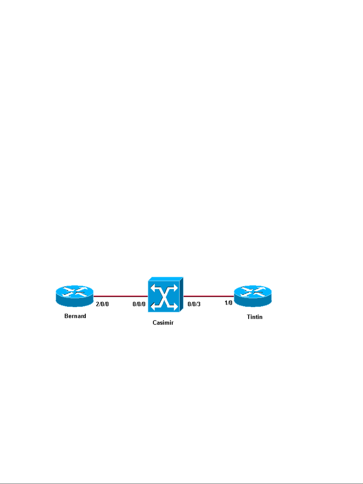
This setup illustrates the problem:
This setup uses:
Bernard is a Cisco 7500 router running Cisco IOS® software release 12.1(4).•
Casimir is a LightStream 1010 running Cisco IOS software release 12.0(13)W5(19b)•
Tintin is a Cisco 7000 router running Cisco IOS software release 11.2(22)P.•
This setup uses LANE, and the LECS and LES/BUS are located on the LightStream 1010.
Note: The configuration used here does not give the best LANE performances; it is simply being used for
illustration. For design recommendations regarding LANE services, refer to the LANE Design
Recommendations.
Cisco − ILMI Address Registration Problems: %LANE−3−NOREGILMI
Page 4

Configurations
Both Bernard and Tintin are configured with a LEC:
Bernard
interface ATM2/0/0
pvc 0/16 ilmi
!
pvc 0/5 qsaal
!
interface ATM2/0/0.1 multipoint
description *** ILMI addr. registr. test ***
lane client ethernet ilmi−test
Tintin
interface ATM1/0
atm pvc 1 0 5 qsaal
atm pvc 2 0 16 ilmi
!
interface ATM1/0.1 multipoint
description *** ILMI addr. registr. test ***
lane client ethernet ilmi−test
Checking ILMI
ILMI Status
The first thing to check in the case of address registration problems through ILMI is whether the ILMI
permanent virtual circuit (PVC) is up using these show commands:
On a router, issue the show atm vc command.•
On a LightStream 1010, issue the show atm vc interface atm x/y/z command.•
bernard# show atm vc
VCD / Peak Avg/Min Burst
Interface Name VPI VCI Type Encaps SC Kbps Kbps Cells Sts
2/0/0 9 0 5 PVC SAAL UBR 149760 UP
2/0/0 1 0 16 PVC ILMI UBR 149760 UP
!−−− Output suppressed.
Casimir# show atm vc interface atm 0/0/0
Interface VPI VCI Type X−Interface X−VPI X−VCI Encap Status
ATM0/0/0 0 5 PVC ATM2/0/0 0 47 QSAAL UP
ATM0/0/0 0 16 PVC ATM2/0/0 0 35 ILMI UP
!−−− Output suppressed.
If the ILMI PVC is up, then you must check which ILMI state the router and the atm switch are in. Do this by
issuing the show atm ilmi−status command.
Cisco − ILMI Address Registration Problems: %LANE−3−NOREGILMI
Page 5

bernard# show atm ilmi−status
Interface : ATM2/0/0 Interface Type : Private UNI (User−side)
ILMI VCC : (0, 16) ILMI Keepalive : Disabled
ILMI State: UpAndNormal
Peer IP Addr: 10.200.10.12 Peer IF Name: ATM0/0/0
Peer MaxVPIbits: 8 Peer MaxVCIbits: 14
Active Prefix(s) :
47.0091.8100.0000.0060.3e5a.4501
Casimir# show atm ilmi−status atm 0/0/0
Interface : ATM0/0/0 Interface Type : Private UNI (Network−side)
ILMI VCC : (0, 16) ILMI Keepalive : Enabled (5 Sec 4 Retries)
ILMI State: UpAndNormal
Peer IP Addr: 15.1.1.1 Peer IF Name: ATM2/0/0
Peer MaxVPIbits: 8 Peer MaxVCIbits: 16
Configured Prefix(s) :
47.0091.8100.0000.0060.3e5a.4501
The correct state is UpAndNormal. If the router or the LightStream 1010 are not in the proper ILMI state,
check if there is a misconfiguration using the instructions given later in this document.
When ILMI is Disabled on the Switch Interface
You can check whether or nor ILMI is disabled on the switch interface by issuing these show commands:
show run interface atm x/y/z•
show atm ilmi−status atm z/y/z•
Casimir# show run interface atm 0/0/0
Building configuration...
Current configuration:
!
interface ATM0/0/0
no ip address
no ip directed−broadcast
logging event subif−link−status
atm ilmi−keepalive
no atm ilmi−enable
bernard# show atm ilmi−status atm 2/0/0
Interface : ATM2/0/0 Interface Type : Private UNI (User−side)
ILMI VCC : (0, 16) ILMI Keepalive : Disabled
ILMI State: UpAndNormal
Peer IP Addr: 0.0.0.0
Peer MaxVPIbits: 8 Peer MaxVCIbits: 14
bernard# show lane default−atm−addresses interface atm 2/0/0
LANE Client: ...000000000002.**
LANE Server: ...000000000003.**
LANE Bus: ...000000000004.**
LANE Config Server: ...000000000005.00
note: ** is the subinterface number byte in hex
Casimir#
Cisco − ILMI Address Registration Problems: %LANE−3−NOREGILMI
Page 6

In this case, as ILMI has been disabled on the interface by issuing the no atm ilmi−enable command, the
prefix is not sent to the router and hence, no address registration can occur.
Access List Configuration Problems or ILMI Community Configured as
Read−Only
Access List configuration problems can occur if one of the workarounds proposed in this security notice is
wrongly applied to the LightStream 1010 or the router. If you have added these lines to the switch
configuration, ILMI (and PNNI) stop working on the switch:
access−list deny any
snmp community ILMI view *ilmi RW
This has the following result:
bernard# show atm ilmi−st
Interface : ATM2/0/0 Interface Type : Private UNI (User−side)
ILMI VCC : (0, 16) ILMI Keepalive : Disabled
ILMI State: WaitDevType
As you can see, the ILMI−status on the router stays in WaitDevType and address registration does not occur.
Adding the following configuration on the router or the switch will also cause ILMI to stay in WaitDevType
and thus prevent any address registration:
access−list <x> [permit|deny] a.b.c.d
snmp−server community ILMI RO <x>
If the router and the switch are in a correct states, then you must check whether cells are being sent and
received on the VC 0/16. You can do this issuing the commands described in the introduction of this
document. You can verify this on a router by issuing these show commands:
show atm pvc 0/16•
show atm vc vcd•
On a LightStream 1010 or Catalyst 8500 MSR, issue these show commands:
show atm vc interface atm x/y/z 0 16•
show atm vc traffic interface atm x/y/z 0 16•
bernard# show atm pvc 0/16
ATM2/0/0: VCD: 1, VPI: 0, VCI: 16
UBR, PeakRate: 149760
AAL5−ILMI, etype:0x0, Flags: 0xC27, VCmode: 0x0
OAM frequency: 0 second(s), OAM retry frequency:
1 second(s), OAM retry frequency: 1 second(s)
OAM up retry count: 3, OAM down retry count: 5
OAM Loopback status: OAM Disabled
OAM VC state: Not Managed
ILMI VC state: Not Managed
InARP DISABLED
Transmit priority 4
InPkts: 255, OutPkts: 309, InBytes: 18842, OutBytes: 22657
InPRoc: 269, OutPRoc: 319, Broadcasts: 0
!−−− Output suppressed.
Cisco − ILMI Address Registration Problems: %LANE−3−NOREGILMI
Page 7

Casimir# show atm vc traffic interface atm 0/0/0 0 16
Interface VPI VCI Type rx−cell−cnts tx−cell−cnts
ATM0/0/0 0 16 PVC 308 316
If you see only the sent or received counter incrementing, it may means that cells are being stuck on the
backplane causing ILMI to be stuck. Try issuing a shut/no shut command on the interface. If that does not
help, contact Cisco Technical Support for further troubleshooting. If both counters are incrementing, then the
ILMI PVC is transmitting cells properly.
Known Caveats
There are also some known bugs which can explain why ILMI is not coming up properly. These are Cisco
Bug IDs CSCdt47492, CSCdm26756 and CSCdr28332.
To follow the bug ID link below and see detailed bug information, you must be a user and you must be .
The rest of this document assumes that the ILMI PVC is UP and carrying cells and that the ILMI status is
correct on all the devices. Then, the possible causes for address registration failures via ILMI are:
The switch already knows the NSAP address•
Configuration problem•
If the Switch Knows the NSAP Address
These are scenarios in which the switch already knows the NSAP address.
When the NSAP Address Is Configured Statically on the Switch
On the router Bernard, you can see this message:
1w1d: %LANE−3−NOREGILMI: ATM2/0/0.1 LEC cannot register
47.00918100000000603E5A4501.00D0069A7C40.01 with ILMI
When looking on the switch for the NSAP address 47.00918100000000603E5A4501.00D0069A7C40.01, you
can see this information:
Casimir# show atm route 47.0091.8100.0000.0060.3e5a.4501.00d0.069a.7c40.01
Codes: I − internal prefix, E − exterior prefix
E 47.0091.8100.0000.0060.3e5a.4501.00d0.069a.7c40/152
Advertised in PTSE ID 3 IG IX 0 by node−index 1
Node 1: Port ATM0/0/3, by atm−static, 00:00:39, uni scope 15
adv_trig 0x2, src_mask 0x1, node−index 0, rtaddr_index 1
Casimir# show atm route
Codes: P − installing Protocol (S − Static, P − PNNI, R − Routing control),
T − Type (I − Internal prefix, E − Exterior prefix, SE −
Summary Exterior prefix, SI − Summary Internal prefix,
ZE − Suppress Summary Exterior, ZI − Suppress Summary Internal)
P T Node/Port St Lev Prefix
~ ~~ ~~~~~~~~~~~~~~~~ ~~ ~~~ ~~~~~~~~~~~~~~~~~~~~~~~~~~~~~~~~~~~~~~~~~~~~~~~~~~~
P I 9 0 UP 0 47.0091.8100.0000.0010.1f2d.6801/104
P SI 1 0 UP 0 47.0091.8100.0000.0060.3e5a.4501/104
R I 1 ATM0/0/3 UP 0 47.0091.8100.0000.0060.3e5a.4501.0000.0c0e.09e7/152
Cisco − ILMI Address Registration Problems: %LANE−3−NOREGILMI
Page 8

R I 1 ATM2/0/0 UP 0 47.0091.8100.0000.0060.3e5a.4501.0060.3e5a.4501/152
R I 1 ATM2/0/0 UP 0 47.0091.8100.0000.0060.3e5a.4501.0060.3e5a.4502/152
R I 1 ATM2/0/0 UP 0 47.0091.8100.0000.0060.3e5a.4501.0060.3e5a.4503/152
R I 1 ATM2/0/0 UP 0 47.0091.8100.0000.0060.3e5a.4501.0060.3e5a.4504/152
R I 1 ATM2/0/0 UP 0 47.0091.8100.0000.0060.3e5a.4501.0060.3e5a.4505/152
S E 1 ATM0/0/3 UP 0 47.0091.8100.0000.0060.3e5a.4501.00d0.069a.7c40/152
R I 1 ATM2/0/0 UP 0 47.0091.8100.0000.0060.3e5a.4501.4000.0c/128
Casimir# show running−config
Building configuration...
Current configuration:
!
! Last configuration change at 12:28:24 UTC Mon Apr 2 2001
! NVRAM config last updated at 12:28:25 UTC Mon Apr 2 2001
!
version 12.0
!−−− Output suppressed.
atm route 47.0091.8100.0000.0060.3e5a.4501.00d0.069a.7c40... ATM0/0/3
As shown above, the NSAP address has been statically configured on the switch and in this case even points
to a different interface from the one where it should be located.
When the NSAP Address Is Registered via ILMI by Another Device
To simulate this scenario, Tintin and Bernard are configured with the same MAC address.
Bernard
interface ATM2/0/0
mac−address 0000.0000.0001
pvc 0/16 ilmi
!
pvc 0/5 qsaal
Tintin
interface ATM1/0
mac−address 0000.0000.0001
no ip address
atm pvc 1 0 5 qsaal
atm pvc 2 0 16 ilmi
Because they are both connected to the same switch, the NSAP address associated to the LECs configured on
the sub−interfaces atm 2/0/0.1 and atm 1/0.1 is the same:
47.00918100000000603E5A4501.000000000001.01.
Tintin interface atm 1/0.1 has been brought up before atm 2/0/0.1 on Bernard. Therefore, Tintin is the first one
to register the NSAP address 47.00918100000000603E5A4501.000000000001.01 via ILMI. As soon as the
interface atm 2/0/0.1 is brought up on Bernard, this message is displayed:
1w1d: %LANE−3−NOREGILMI: ATM2/0/0.1 LEC cannot register
47.00918100000000603E5A4501.000000000001.01 with ILMI
Cisco − ILMI Address Registration Problems: %LANE−3−NOREGILMI
Page 9

If you look at Tintin, you can see that Tintin is already using that NSAP address and has registered it on
Casimir:
Tintin# show lane client
LE Client ATM1/0.1 ELAN name: ilmi−test Admin: up State: operational
Client ID: 2 LEC up for 39 seconds
Join Attempt: 4
HW Address: 0000.0000.0001 Type: ethernet Max Frame Size: 1516
ATM Address: 47.00918100000000603E5A4501.000000000001.01
VCD rxFrames txFrames Type ATM Address
0 0 0 configure 47.00918100000000603E5A4501.00603E5A4505.00
14 1 2 direct 47.00918100000000603E5A4501.00603E5A4503.01
15 1 0 distribute 47.00918100000000603E5A4501.00603E5A4503.01
16 0 1 send 47.00918100000000603E5A4501.00603E5A4504.01
17 2 0 forward 47.00918100000000603E5A4501.00603E5A4504.01
If you look at Casimir, you can see that this address has already been registered:
Casimir# show atm route 47.00918100000000603E5A4501.000000000001.01
Codes: I − internal prefix, E − exterior prefix
I 47.0091.8100.0000.0060.3e5a.4501.0000.0000.0001/152
Node 1: Port ATM0/0/3, by routing−control, 00:01:06, uni scope 15
adv_trig 0x2, src_mask 0x2, node−index 0, rtaddr_index 1
Casimir# show atm route
Codes: P − installing Protocol (S − Static, P − PNNI, R − Routing control),
T − Type (I − Internal prefix, E − Exterior prefix, SE −
Summary Exterior prefix, SI − Summary Internal prefix,
ZE − Suppress Summary Exterior, ZI − Suppress Summary Internal)
P T Node/Port St Lev Prefix
~ ~~ ~~~~~~~~~~~~~~~~ ~~ ~~~ ~~~~~~~~~~~~~~~~~~~~~~~~~~~~~~~~~~~~~~~~~~~~~~~~~~~
P I 9 0 UP 0 47.0091.8100.0000.0010.1f2d.6801/104
P SI 1 0 UP 0 47.0091.8100.0000.0060.3e5a.4501/104
R I 1 ATM0/0/3 UP 0 47.0091.8100.0000.0060.3e5a.4501.0000.0000.0001/152
R I 1 ATM2/0/0 UP 0 47.0091.8100.0000.0060.3e5a.4501.0060.3e5a.4501/152
R I 1 ATM2/0/0 UP 0 47.0091.8100.0000.0060.3e5a.4501.0060.3e5a.4502/152
R I 1 ATM2/0/0 UP 0 47.0091.8100.0000.0060.3e5a.4501.0060.3e5a.4503/152
R I 1 ATM2/0/0 UP 0 47.0091.8100.0000.0060.3e5a.4501.0060.3e5a.4504/152
R I 1 ATM2/0/0 UP 0 47.0091.8100.0000.0060.3e5a.4501.0060.3e5a.4505/152
S E 1 ATM0/0/3 UP 0 47.0091.8100.0000.0060.3e5a.4501.00d0.069a.7c40/152
R I 1 ATM2/0/0 UP 0 47.0091.8100.0000.0060.3e5a.4501.4000.0c/128
This means that Bernard is not able to register its address via ILMI, since it is a duplicate. When the debug
atm ilmi atm x/y/z command is issued on Bernard and Casimir, these debugs can be seen:
Bernard:
!−−− Output suppressed.
1w1d: ILMI(ATM2/0/0): Registration local validation attempt for
47.0091.8100.0000.0060.3e5a.4501.0000.0000.0001.01
1w1d: ILMI(ATM2/0/0): Sent Out. Will be added on confirmation
1w1d: ILMI(ATM2/0/0):Sending out Request 930
1w1d: ILMI(ATM2/0/0):Response received for request 929
1w1d: ILMI(ATM2/0/0): Errored response <General Error> Function Type = ilmiReqOther
1w1d: ILMI(ATM2/0/0): Errored or no response received
1w1d: ILMI(ATM2/0/0): ES database update not done
Cisco − ILMI Address Registration Problems: %LANE−3−NOREGILMI
Page 10

Casimir:
1w1d: ILMI(ATM2/0/0):Updating ES Database with
7.0091.8100.0000.0060.3e5a.4501.0060.3e5a.4502.00
1w1d: Reg Status :− Delete in progress − False, Add in progress − True
1w1d: ILMI(ATM2/0/0):Response received for request 930
1w1d: ILMI(ATM2/0/0): Errored response <General Error> Function Type = ilmiReqOther
1w1d: ILMI(ATM2/0/0): Errored or no response received
1w1d: ILMI(ATM2/0/0): ES database update not done
1w1d: ILMI(ATM2/0/0):Updating ES Database with
47.0091.8100.0000.0060.3e5a.4501.0000.0000.0001.01
1w1d: Reg Status :− Delete in progress − False, Add in progress − True
1w1d: %LANE−3−NOREGILMI: ATM2/0/0.1 LEC cannot register
47.00918100000000603E5A4501.000000000001.01 with ILMI
!−−− Output suppressed.
!−−− Output suppressed.
Apr 2 13:10:06.800: ILMI: Validating address 47.0091.8100.0000.0060.3e5a.4501.0000.0000.0001.01
Apr 2 13:10:06.800: ILMI: Address rejected by Client identified as pnni(ATM0/0/0)
!−−− Output suppressed.
Note: The situation described in this section can often be encountered in the following scenario. If LECS
services are configured on Cisco devices and other vendor devices at the same time and all these LECS are
listening to the well−known address and advertising it, this message can be displayed:
1w2d: %LANE−3−NOREGILMI: ATM2/0/0 LECS cannot register
47.007900000000000000000000.00A03E000001.00 with ILMI
As LECS are configured on non−Cisco devices as well as Cisco devices, you cannot use SSRP of Fast−SSRP.
The purpose of these redundancy protocols is that one LECS is elected as Master LECS (the others being
backup LECS). The master LECS is the only one allowed to advertise the well−known address if it is being
used. In this case, since you cannot configure a redundancy protocol, there is no Master LECS election.
Hence, all the LECS try to advertise the well−known address, but only one succeeds.
To illustrate this, the configurations have been modified as shown:
Bernard
lane database test
name ilmi−test server−atm−address 47.00918100000000603E5A4501.00603E5A4503.01
!
interface ATM2/0/0
no ip address
no ip route−cache distributed
no atm ilmi−keepalive
pvc 0/16 ilmi
!
pvc 0/5 qsaal
!
lane config fixed−config−atm−address
Cisco − ILMI Address Registration Problems: %LANE−3−NOREGILMI
Page 11

lane config database test
Tintin
lane database test
name ilmi−test server−atm−address 47.00918100000000603E5A4501.00603E5A4503.01
!
interface ATM2/0/0
no ip address
no ip directed−broadcast
logging event subif−link−status
lane config fixed−config−atm−address
lane config database test
With this new configuration, a LECS has been configured on Bernard and Casimir, and no LECS address
database has been configured on Casimir. This means that SSRP is not enabled. To illustrate the error
message, the Bernard atm 2/0/0 interface is shut down before it is configured, and the Casimir configuration is
modified first. In this situation, Casimir advertises the well−known address via ILMI, thus preventing Bernard
from doing so. As soon as the Bernard atm 2/0/0 interface is brought up, this message is displayed:
1w2d: %LANE−3−NOREGILMI: ATM2/0/0 LECS cannot register
47.007900000000000000000000.00A03E000001.00 with ILMI
Configuration Problems
Another possible cause of failure of the address registration is a problem with the configuration on the
LightStream 1010.
interface ATM0/0/0
no ip address
no ip directed−broadcast
logging event subif−link−status
atm ilmi−keepalive
no atm address−registration
The command above prevents any address registration via ILMI which, in this case, prevents the router from
receiving its prefix, and thus also advertising its address to the switch:
bernard# show lane default−atm−addresses interface atm 2/0/0
LANE Client: ...000000000002.**
LANE Server: ...000000000003.**
LANE Bus: ...000000000004.**
LANE Config Server: ...000000000005.00
note: ** is the subinterface number byte in hex
bernard# show atm ilmi−status atm 2/0/0
Interface : ATM2/0/0 Interface Type : Private UNI (User−side)
ILMI VCC : (0, 16) ILMI Keepalive : Disabled
ILMI State: UpAndNormal
Peer IP Addr: 10.200.10.12 Peer IF Name: ATM0/0/0
Peer MaxVPIbits: 8 Peer MaxVCIbits: 14
Cisco − ILMI Address Registration Problems: %LANE−3−NOREGILMI
Page 12

The router does not receive its prefix and hence no address−registration can occur.
When enabling debug atm ilmi atm 0/0/0 on the LightStream 1010, this can be seen when the atm 0/0/0
interface is brought up:
!−−− Output suppressed.
Apr 2 12:42:11.792: ILMI: My Device type is set to Node (ATM0/0/0)
Apr 2 12:42:11.792: ILMI(ATM0/0/0): From NodeConfigComplete To UpAndNormal <ilmi_process_intfRestart>
Apr 2 12:42:11.792: ILMI(ATM0/0/0): Keep Alive enabled
Apr 2 12:42:11.792: ILMI(ATM0/0/0) Address Registration disabled. Prefix not sent
!−−− Output suppressed.
The solution is to re−enable atm address−registration and do a shut/no shut on the atm interface to restart
ILMI.
Related Information
LANE Design Recommendations•
SSRP Sample Configuration•
FSSRP Sample Configuration•
Configuring LANE•
Troubleshooting ATM LAN Emulation Networks•
LANE Technology Support•
Technical Support − Cisco Systems•
All contents are Copyright © 1992−2005 Cisco Systems, Inc. All rights reserved. Important Notices and Privacy Statement.
Updated: May 11, 2005 Document ID: 10450
Cisco − ILMI Address Registration Problems: %LANE−3−NOREGILMI
 Loading...