

Page 1

Configuring Cisco Access Routers and the
NME-WAE Network Module for ACNS
Deployments
April 14, 2008
This document describes how to configure the Cisco access router and the Cisco Wide Area Application
Engine network module (NME-WAE) for Application and Content Networking System (ACNS)
software deployments.
The WAE network module is a standalone Wide Area Application Engine (WAE) that plugs into a host
Cisco access router. The host router runs Cisco IOS software, while the WAE network module has its
own startup and run-time configurations that are independent of the IOS configuration on the router.
Contents
ACNS software is a Linux-based application that resides on the WAE network module. ACNS software
offers the following content-based services:
• Content caching and hosting
• Proxy services
• Content replication
• Video streaming
The host router and the network module combined provide a router-integrated application platform for
accelerating data-intensive applications.
• Prerequisites for Installing the Cisco WAE Network Modules, page 2
• Restrictions for Cisco WAE Network Modules, page 2
• Cisco WAE Network Module Hardware Description, page 3
• Setting Up Cisco WAE Network Modules and Opening a Session, page 5
• Starting the Cisco WAE Network Module and Displaying Status, page 10
• Command Reference, page 15
Americas Headquarters:
Cisco Systems, Inc., 170 West Tasman Drive, San Jose, CA 95134-1706 USA
© 2007-2008 Cisco Systems, Inc. All rights reserved.
Page 2

Prerequisites for Installing the Cisco WAE Network Modules
• Glossary, page 37
• Related Documentation, page 38
• Obtaining Documentation, Obtaining Support, and Security Guidelines, page 39
Prerequisites for Installing the Cisco WAE Network Modules
The prerequisites for installing the Cisco WAE network module in the access router are as follows:
• Plan software upgrades or downgrades for times when you can take all applications that run on the
host router offline.
• Ensure that you have the appropriate Cisco access router to serve as the host router. The WAE
network module is supported on the following Cisco access routers:
–
2811, 2821, and 2851
–
3725, 3825, and 3845
• Ensure that the router is running IOS Release 12.4(9)T or 12.4(9)T1 (recommended) by using the
show version command.
When minimum release requirements are met, you can change images on either the router or the
network modules without affecting performance.
• For information about installing the NME-WAE, see the Quick Start Guide: Network Modules for
Cisco Access Routers and Cisco Network Modules and Interface Cards Regulatory Compliance and
Safety Information.
• You need the slot and unit numbers for the “Setting Up Network Module Interfaces” section on
page 6 and the “Opening and Closing a Network Module Session” section on page 8. Make a note
of the network module location in the host router:
–
slot—Slot number of the network module in the router chassis. After you install the module,
you can obtain this information from the router show running-config command output.
–
unit—Number of the daughter card on the module. This value is always 0.
• You need an accessible FTP or TFTP file server.
–
Use an FTP file server for installations, backups, and restores.
–
Use a TFTP file server (on the FTP-file-server machine) for boothelper operations to recover
from a failed installation.
Restrictions for Cisco WAE Network Modules
The restrictions for the Cisco WAE network modules are as follows:
• You may perform a software upgrade or downgrade only on an inactive appliance. Plan upgrades or
downgrades for times when you can take all applications that run on the host router out of service
or offline.
• All WAE appliances and network modules that are in your network must be running the same version
of the ACNS software.
• Network module software configurations can only be performed by using a console that connects to
a single serial-port console port on the host router.
Configuring Cisco Access Routers and the NME-WAE Network Module for ACNS Deployments
2
OL-13140-02
Page 3

Cisco WAE Network Module Hardware Description
Because the network module does not have an external console port, you must configure the network
module by initiating a Telnet session or by initiating a configuration session from the router CLI.
• After initial setup, which requires using router configuration commands, you can configure the
NME-WAE in the same manner as other ACNS devices, with the following exceptions:
–
The NME-WAE cannot serve as a Content Distribution Manager for other ACNS devices.
–
The NME-WAE does not support device mode configuration. The device mode configuration
prompt has been removed from the NME-WAE startup script.
–
Websense URL-filtering is not supported on the NME-WAE.
• ACNS software does not support the following hardware-related features on the network module:
–
USB port
–
Compact Flash utilization LED
–
Software reset button
Cisco WAE Network Module Hardware Description
This section includes the following topics describing the WAE network module hardware:
• Hard Disk and Memory Specifications
• Faceplate and LEDs
• Hardware Interfaces
Hard Disk and Memory Specifications
The NME-WAE ships from the factory with the hardware listed in Tab l e 1 preinstalled.
Table 1 Network Module Hardware
Model Hard Disk Memory
NME-WAE-502-K9 120 GB 1 GB
NME-WAE-522-K9 160 GB 2 GB
Faceplate and LEDs
Figure 1 shows the NME-WAE faceplate and LEDs.
OL-13140-02
Configuring Cisco Access Routers and the NME-WAE Network Module for ACNS Deployments
3
Page 4

Cisco WAE Network Module Hardware Description
Figure 1 NME-WAE Faceplate and LEDs
NM-WAE-XXX-K9
XXX-XXXXX-XX XX
SHUTDOWN:
GRACEFUL <1 s
IMMEDIATE >4 s
CF
Never remove compact
flash during operation
LINK ACT
GigE
DISK
SYS
USB
NOT
SUPPORTED
Shut down
application
before removing or
power cycling.
EN
170900
CF
Shutdown
CF card
LINK ACT DISK
SYS
EN
CF Not used
Shutdown Press the Shutdown button for greater than 4 seconds to cause an immediate module
shutdown, which may impact file operations that are in progress.
CF card CompactFlash memory card
LINK Status of Gigabit Ethernet link
On—Link is enabled
Off—Link is disabled
ACT Status of Gigabit Ethernet activity
On—Active
Off—Inactive
DISK Status of hard drive activity
On—Active
Off—Inactive
SYS Status of system shutdown
On—System is shut down and ready for host power down
Off—Application is stable
Flashing—System shutdown is in progress
EN Status of the network module
On—Detected by the host IOS software and enabled
Off—Disabled
Configuring Cisco Access Routers and the NME-WAE Network Module for ACNS Deployments
4
OL-13140-02
Page 5
Hardware Interfaces
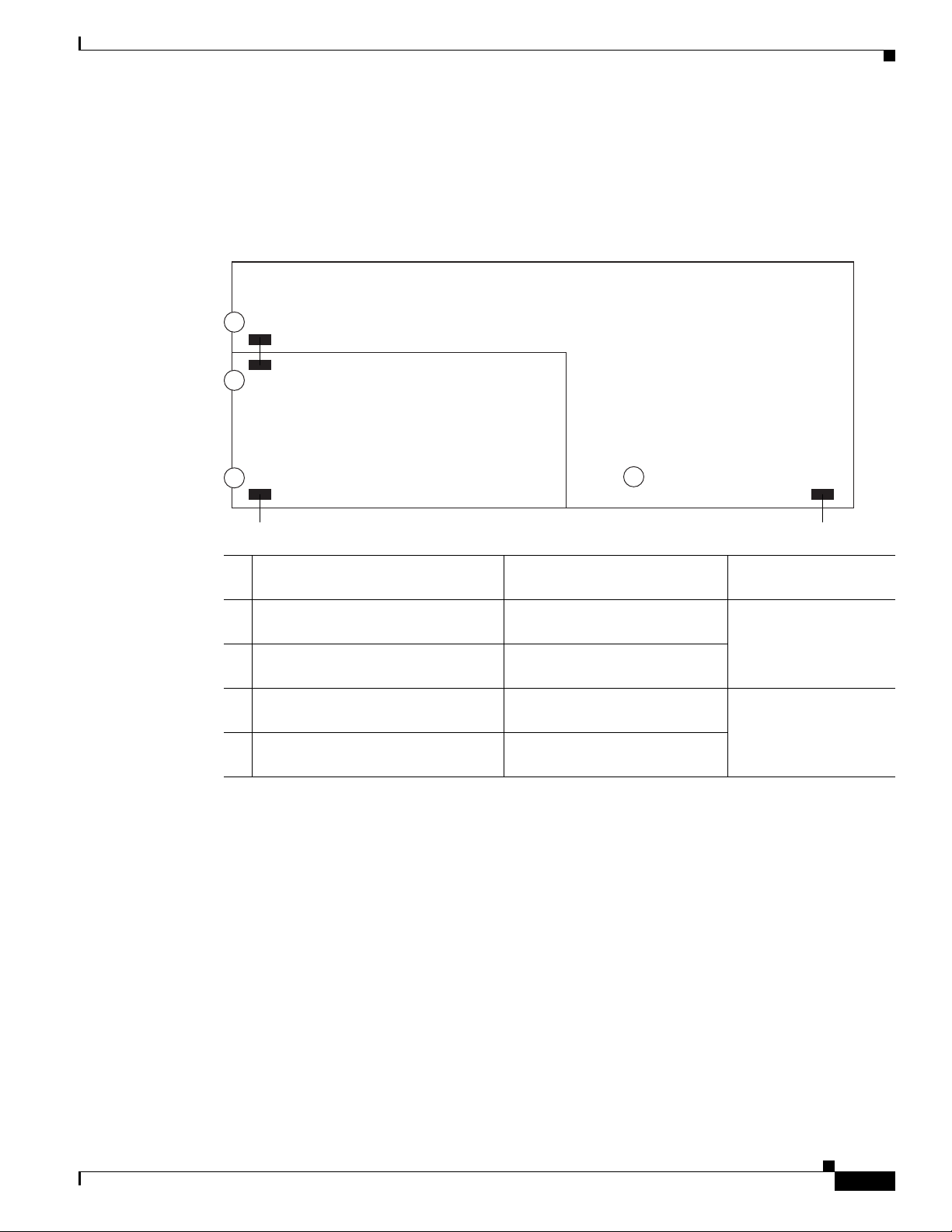
The host router and network module use several interfaces for internal and external communication (see
Figure 2). Each interface is configurable by using a IOS-like CLI.
Figure 2 Router and Network Module Interface
2
Router interface to module
3
Module interface to router
Module interface to external link
4
Network Module
Setting Up Cisco WAE Network Modules and Opening a Session
Host Router (Top View)
1
Router interface to external link
231229
Using This
On This Hardware Interface... Configure These Settings...
1 Router interface to external link
Standard router settings Router IOS
(GigabitEthernet slot/0)
2 Router interface to module
(Integrated-Service-Engine slot/0)
3 Module interface to router
(Integrated-Service-Engine slot/0)
4 Module interface to external link
(Integrated-Service-Engine slot/0)
Module IP address and default
gateway router
All other module and ACNS
application settings
All other module and ACNS
application settings
Configuration Interface
command-line interface
NME-WAE network
module command-line
interface
The NME-WAE accepts traffic to be optimized on either its internal or external interface but not on both
interfaces. Configure either the module internal interface to the router (see callout 3 in Figure 2) or the
module external interface (see callout 4 in Figure 2) but not both interfaces.
When using the ACNS Content Distribution Manager GUI for an NME-WAE device, the internal
interface to the router is designated as slot 1, port 0 and the external network interface is designated as
slot 2, port 0, regardless of the physical slot in which the NME-WAE is installed.
Setting Up Cisco WAE Network Modules and Opening a Session
This section contains the following topics:
• Setting Up Network Module Interfaces, page 6
OL-13140-02
• Opening and Closing a Network Module Session, page 8
Configuring Cisco Access Routers and the NME-WAE Network Module for ACNS Deployments
5
Page 6

Setting Up Cisco WAE Network Modules and Opening a Session
If you lose power or connection during any of the following procedures, the software usually detects the
interruption and tries to recover. If it fails to recover, reinstall the software using the boothelper.
You can configure basic network parameters for the network module by using the CLI, which is
described in this document. For additional configuration instructions, see the ACNS online help that is
included with the software application.
Setting Up Network Module Interfaces
Your first configuration task is to configure the network module interfaces to the host router and to its
external links. You use these interfaces to access the module for installing and configuring the ACNS
software application.
This section includes the following topics:
• Summary Steps
• Detailed Steps
• Examples
The first several steps open the host router CLI to the module. The subsequent steps configure the
interface.
Summary Steps
The network module is referred to as the integrated service engine (ISE) on the IOS CLI.
From the host router CLI, use the following commands:
1. enable
2. configure terminal
3. interface integrated-service-engine slot/0
4. ip address router-side-ip-address subnet-mask
5. service-module ip address module-side-ip-address subnet-mask
or
service-module external ip address module-side-ip-address subnet-mask
6. service-module ip default-gateway gateway-ip-address
7. end
8. copy running-config startup-config
9. show running-config
Configuring Cisco Access Routers and the NME-WAE Network Module for ACNS Deployments
6
OL-13140-02
Page 7

Detailed Steps
Procedure Command
Step 1
Step 2
Step 3
Step 4
Step 5
Enter privileged EXEC mode on the host router. Enter
your password if prompted.
Enter global configuration mode on the host router.
Enter interface configuration mode for the slot where the
network module resides.
Specify the router interface to the module (see callout 2 in
Figure 2). Arguments are as follows:
• router-side-ip-address subnet-mask—IP address and
subnet mask for the interface.
Specify the IP address for the module interface to the
router (see callout 3 in Figure 2). To configure the
external interface (see callout 4 in Figure 2) instead of the
internal interface, use the second form of the command.
Arguments are as follows:
• module-side-ip-address—IP address for the interface.
• subnet-mask—Subnet mask to append to the IP
address; must be in the same subnet as the host router
subnet specified in Step 4.
Setting Up Cisco WAE Network Modules and Opening a Session
From the host router CLI, perform the following steps:
enable
Example:
Router> enable
configure terminal
Example:
Router# configure terminal
interface integrated-service-engine slot/0
Example:
Router(config)# interface
integrated-service-engine 1/0
ip address router-side-ip-address subnet-mask
Example:
Router(config-if)# ip address 10.0.0.20
255.255.255.0
service-module ip address module-side-ip-address
subnet-mask
or
service-module external ip address
module-side-ip-address subnet-mask
Example:
Router(config-if)# service-module ip address
10.0.0.30 255.255.255.0
Step 6
Step 7
OL-13140-02
Specify the IP address for the default gateway router for
the module. The argument is as follows:
• gateway-ip-address—IP address for the gateway
router.
Return to global configuration mode on the host router.
Configuring Cisco Access Routers and the NME-WAE Network Module for ACNS Deployments
or
Router(config-if)# service-module external ip
address 10.0.0.30 255.255.255.0
service-module ip default-gateway
gateway-ip-address
Example:
Router(config-if)# service-module ip
default-gateway 10.0.0.20
end
Example:
Router(config-if)# end
7
Page 8

Setting Up Cisco WAE Network Modules and Opening a Session
Procedure Command
Step 8
Step 9
Save the router running configuration.
Display the router running configuration so that you can
verify interface configurations.
Examples
The following partial output from the show running-config command shows how the interfaces are
configured:
interface service-engine1/0
ip address 10.0.0.20 255.255.255.0
service-module integrated-service-engine ip address 10.0.0.30 255.255.255.0
service-module integrated-service-engine ip default-gateway 10.0.0.20
copy running-config startup-config
Example:
Router# copy running-config startup-config
show running-config
Example:
Router# show running-config
Opening and Closing a Network Module Session
Once you have set up your network interfaces, you can open and close a session on the network module.
Opening a session is the equivalent of accessing an ACNS appliance from its console. You can conduct
only one session at a time.
The procedure listed below uses the service-module integrated-service-engine slot/0 session command
to open a session. Alternatively, you can access the network module console by telneting to a specific
port at the network module IP address, depending on the slot where the network module is installed, as
follows:
• slot 1—telnet to port 2066
• slot 2—telnet to port 2130
• slot 3—telnet to port 2194
• slot 4—telnet to port 2258
This section includes the following topics:
• Summary Steps
• Detailed Steps
• Where to go Next
Summary Steps
To open a network module session, use the following commands from the host router CLI:
1. enable
2. service-module integrated-service-engine slot/0 status
3. service-module integrated-service-engine slot/0 session
Configuring Cisco Access Routers and the NME-WAE Network Module for ACNS Deployments
8
OL-13140-02
Page 9

Detailed Steps
Procedure Command
Step 1
Step 2
Step 3
From the host router CLI, enter privileged EXEC mode on
the host router. Enter your password if prompted.
Display the status of the specified module so that you can
ensure that the module is running (that is, in the steady
state). For details, see the service-module
integrated-service-engine status command.
If the module is not running, start it with one of the startup
commands listed in the “Shutting Down and Starting Up
Cisco WAE Network Modules” section on page 11.
Begin a service module session on the specified module.
Perform one of the following actions:
Setting Up Cisco WAE Network Modules and Opening a Session
Use the following commands from the Network Module Interface
4. Log in to the network module.
5. Perform configuration or other procedures by using the ACNS CLI.
6. Press Control-Shift-6 x.
Use the following command from the host router CLI:
7. service-module integrated-service-engine slot/0 session clear
To open a network module session, perform the following steps:
enable
Example:
Router> enable
service-module integrated-service-engine slot/0
status
Example:
Router# service-module
integrated-service-engine 2/0 status
service-module integrated-service-engine slot/0
session
Step 4
OL-13140-02
• To interrupt the auto-boot sequence and access the
bootloader, quickly type ***.
• To start a configuration session, press Enter.
To use telnet to access the network module, use the second
form of the command.
From the network module interface, log in to the network
module. The default username is admin and the default
password is default.
Configuring Cisco Access Routers and the NME-WAE Network Module for ACNS Deployments
or
telnet module-ip-address port
Example:
Router# service-module
integrated-service-engine 1/0 session
Trying 10.10.10.1, 2066 ... Open
or
Router# telnet 10.10.10.1 2066
Cisco Content Engine Console
Username: admin
Password:
System Initialization Finished.
SE-Module#
9
Page 10

Starting the Cisco WAE Network Module and Displaying Status
Procedure Command
Step 5
Enter configuration commands on the module as needed.
Configuration command choices are similar to those
commands that are available on the router. Access global
configuration mode by using the configure terminal
command. Enter configuration commands. Then exit global
configuration mode with the exit command and save your
new configuration with the write command.
Step 6
Close the service module session and return to the router
CLI.
The service module session remains active until you clear it
in the next step. While it remains active, you can return to it
from the router CLI by pressing Enter.
Step 7
From the host router CLI, clear the service module session
for the specified module. When prompted to confirm this
command, press Enter.
Example (Configuration):
SE-Module# configure terminal
SE-Module(config)#
.
.
.
SE-Module(config)# exit
SE-Module# write
Press Ctrl-Shift-6 x.
service-module integrated-service-engine slot/0
session clear
Example:
Router# service-module
integrated-service-engine 1/0 session clear
Where to go Next
See the “Starting the Cisco WAE Network Module and Displaying Status” section on page 10 for
information about maintaining and administering the WAE network module.
See the “Command Reference” section on page 15 for a list of new and modified IOS commands used
to configure the WAE network module.
Starting the Cisco WAE Network Module and Displaying Status
This section contains the following topics:
• Accessing the ACNS Software on the Network Module
• Shutting Down and Starting Up Cisco WAE Network Modules, page 11
• Displaying Status and Diagnostic Output, page 12
The tables in these sections list only the most common router and network module commands. The tables
group commands by the configuration mode in which they are available. If the same command is
available in more than one mode, it may act differently in each mode.
To view a complete list of available commands, type ? at the prompt, as shown in the following example:
Router(config-if)# ?
To view a complete list of command keyword options, type ? at the end of the command, as shown in
the following example:
Router# service-module integrated-service-engine ?
10
Configuring Cisco Access Routers and the NME-WAE Network Module for ACNS Deployments
OL-13140-02
Page 11

Starting the Cisco WAE Network Module and Displaying Status
Accessing the ACNS Software on the Network Module
You can access the ACNS software that runs on the network module by first accessing one of the
following:
• The router IOS command-line interface (CLI) to open a console session to the network module
• The ACNS Content Distribution Manager graphical user interface (GUI)
For details about configuring and maintaining your ACNS network, see the following documents:
• Cisco Application and Content Networking System Software Configuration Guide for Centrally
Managed Deployments
• Cisco Application and Content Networking System Software Configuration Guide for Locally
Managed Deployments
• Cisco Application and Content Networking System Software Command Reference
When using the ACNS Content Distribution Manager GUI for an NME-WAE device, the internal
interface to the router is designated as slot 1, port 0 and the external network interface is designated as
slot 2, port 0, regardless of the physical slot in which the NME-WAE is installed.
Shutting Down and Starting Up Cisco WAE Network Modules
To shut down or start up the network module or the ACNS software that runs on the module, use a
command from the common router and network module commands listed in Table 2.
Be aware of the following command functions:
• Shutdown commands can potentially disrupt service. The command output will display a
confirmation prompt before shutdown occurs. Confirm by pressing Enter or cancel by typing n and
pressing Enter. To prevent the prompt from displaying, use the no-confirm keyword.
• Some commands shut the module or application down and then immediately restart it.
Table 2 Common Shutdown and Startup Commands
Configuration Mode Command Purpose
Router#
Router#
service-module
integrated-service-engine
slot/0 reload
service-module
integrated-service-engine
slot/0 reset
Shuts down the network module operating
system gracefully and then restarts it from
the bootloader.
Resets the hardware on a module. Use this
command only to recover from shutdown or
a failed state.
Caution Using this command does not
provide an orderly software
shutdown and may impact file
operations that are in progress.
OL-13140-02
Router#
service-module
integrated-service-engine
slot/0 session
Configuring Cisco Access Routers and the NME-WAE Network Module for ACNS Deployments
Accesses the specified service engine and
begins a network module configuration
session.
11
Page 12

Starting the Cisco WAE Network Module and Displaying Status
Table 2 Common Shutdown and Startup Commands (continued)
Configuration Mode Command Purpose
Router#
service-module
integrated-service-engine
slot/0 shutdown
Router#
service-module
integrated-service-engine
slot/0 status
Router#
SE-Module#
SE-Module#
shutdown Shuts down the entire system (both the host
reload Shuts down ACNS gracefully, and then
shutdown Shuts down the ACNS application
Displaying Status and Diagnostic Output
Shuts down the network module operating
system gracefully. Use when removing or
replacing a hot-swappable module during
online insertion and removal (OIR).
Displays configuration and status
information for the network module
hardware and software.
router and the service module) gracefully.
reboots it from the bootloader.
gracefully, and then shuts down the module.
To verify the status of an installation, upgrade, or downgrade, or to troubleshoot problems, use the
commands as needed from the common router and network module commands listed in Tabl e 3.
Many show commands provide keyword options to display diagnostic output on your screen or to send
the output to a file or a URL.
Table 3 Common Verification and Troubleshooting Commands
Configuration Mode Command Purpose
Router#
ping Pings a specified IP address to check
network connectivity (does not accept a
hostname as destination).
Router#
show arp Displays the current Address Resolution
Protocol (ARP) table.
Router#
Router#
show clock Displays the current date and time.
show configuration Displays the current bootloader
configuration as entered by means of the
configure command.
Router#
show controllers
Displays interface debug information.
integrated-service-engine
Router#
show diag Displays standard IOS diagnostic
information including information about the
ACNS software.
Router#
show hardware Displays information about network module
and host router hardware.
Router#
show hosts Displays the default domain name, style of
name lookup, list of name-server hosts, and
cached list of hostnames and addresses.
12
Configuring Cisco Access Routers and the NME-WAE Network Module for ACNS Deployments
OL-13140-02
Page 13

Starting the Cisco WAE Network Module and Displaying Status
Table 3 Common Verification and Troubleshooting Commands (continued)
Configuration Mode Command Purpose
Router#
Router#
Router#
Router#
Router#
Router#
Router#
Router#
Router#
Router#
SE-Module#
SE-Module#
SE-Module#
SE-Module#
SE-Module#
SE-Module#
SE-Module#
SE-Module#
SE-Module#
SE-Module#
show interfaces Displays information about hardware
interfaces, including the network and the
disk.
show interfaces
integrated-service-engine
Displays information about the module side
of the router-module interface.
show ntp status Displays information about the Network
Time Protocol (NTP).
show processes Displays a list of the application processes
that are running.
show running-config Displays the configuration commands that
are in effect.
show startup-config Displays the startup configuration.
show tech-support Displays general information about the host
router. This information is useful to Cisco
technical support for problem diagnosis.
show version Displays information about the loaded router
software or network module bootloader
version as well as hardware and device
information.
test scp ping Pings the service module to check network
connectivity.
verify Displays version information for installed
hardware and software.
ping Pings a specified IP address to check
network connectivity (does not accept a
hostname as destination).
show arp Displays the current Address Resolution
Protocol (ARP) table.
show clock Displays the current date and time.
show config Displays the startup configuration stored on
the CompactFlash drive.
show hosts Displays the default IP domain name, lookup
style, name servers, and host table.
show interfaces interfacename Displays information about the network
module interfaces.
show ntp status Displays information about the Network
Time Protocol (NTP).
show processes Displays a list of the application processes
that are running.
show running-config Displays the configuration commands that
are in effect.
show startup-config Displays the startup configuration.
OL-13140-02
Configuring Cisco Access Routers and the NME-WAE Network Module for ACNS Deployments
13
Page 14

Starting the Cisco WAE Network Module and Displaying Status
Table 3 Common Verification and Troubleshooting Commands (continued)
Configuration Mode Command Purpose
SE-Module#
SE-Module#
show tech-support Displays general information about the
show version Displays information about the loaded router
service module. This information is useful to
Cisco technical support for problem
diagnosis.
software or network module bootloader
version and also hardware and device
information.
14
Configuring Cisco Access Routers and the NME-WAE Network Module for ACNS Deployments
OL-13140-02
Page 15

Command Reference
This section documents the module-specific IOS router commands that are used to configure the WAE
network module from the router command-line interface (CLI). All other IOS software commands used
with this feature are documented in the IOS Release 12.4(9) T command reference publication.
The network module is also known as the integrated-service-engine within the IOS CLI.
• interface integrated-service-engine, page 16
• service-module integrated-service-engine default-boot, page 17
• service-module integrated-service-engine reload, page 18
• service-module integrated-service-engine reset, page 19
• service-module integrated-service-engine session, page 21
• service-module integrated-service-engine shutdown, page 23
• service-module integrated-service-engine statistics, page 25
• service-module integrated-service-engine status, page 26
• show controllers integrated-service-engine, page 28
• show interfaces integrated-service-engine, page 33
Command Reference
• show diag, page 30—Modified command
OL-13140-02
Configuring Cisco Access Routers and the NME-WAE Network Module for ACNS Deployments
15
Page 16

interface integrated-service-engine
interface integrated-service-engine
To enter the interface configuration mode for an integrated-service-engine (ISE) network module, use
the interface integrated-service-engine command in global configuration mode.
interface integrated-service-engine slot/unit
Syntax Description
Defaults None
Command Modes Global configuration
Command History
Usage Guidelines This command is used only for ISE network modules. If your router does not have this hardware, then
slot Slot number of the interface.
unit Number of the daughter card on the network module. For ISE network
modules, always use 0.
Release Modification
12.4(9)T This command was introduced for ISE network modules.
you will not be able to enter this command.
A no form of this command (no interface integrated-service-engine) is not available. Use the exit
command to exit the interface configuration mode.
Examples The following example shows how to enter configuration mode for ISE network modules located in slot
1, unit 0:
Router (config)# interface integrated-service-engine 1/0
Router (config-if)# exit
Configuring Cisco Access Routers and the NME-WAE Network Module for ACNS Deployments
16
OL-13140-02
Page 17

service-module integrated-service-engine default-boot
service-module integrated-service-engine default-boot
To configure the integrated-service-engine (ISE) network module to use the default BIOS and
bootloader, use the service-module integrated-service-engine default-boot command in privileged
EXEC mode.
service-module integrated-service-engine slot/unit default-boot
Syntax Description
slot Slot number of the network module in the router chassis.
unit Number of the daughter card on the network module. For ISE network
modules, always use 0.
Defaults None
Command Modes Privileged EXEC
Command History
Release Modification
12.4(9)T This command was introduced for the ISE network module.
Examples After a downtime event or failed upgrade, use the service-module integrated-service-engine slot/unit
default-boot command to configure the network module to use the primary BIOS and primary
bootloader to perform startup routines.
The following is sample output from the integrated-service-engine slot/unit default-boot command for
a port adapter in chassis slot 2 on a Cisco router:
Router# service-module integrated-service-engine 2/0 default-boot
clear Clear Default Boot
set Set Default Boot
Router# service-module integrated-service-engine 2/0 default-boot clear
Router# service-module integrated-service-engine 2/0 default-boot set
OL-13140-02
Configuring Cisco Access Routers and the NME-WAE Network Module for ACNS Deployments
17
Page 18

service-module integrated-service-engine reload
service-module integrated-service-engine reload
To perform a graceful shutdown and reboot of the integrated-service-engine (ISE) network module
ACNS operating system, use the service-module integrated-service-engine reload command in
privileged EXEC mode.
service-module integrated-service-engine slot/unit reload
Syntax Description
Defaults None
Command Modes Privileged EXEC
Command History
Usage Guidelines At the confirmation prompt, press Enter to confirm the action or n to cancel.
Examples The following example gracefully shuts down and reboots the ISE network module ACNS operating
slot Slot number of the network module in the router chassis.
/unit Number of the daughter card on the network module. For ISE network
modules, always use 0. The slash mark (/) is required between the slot
argument and the unit argument.
Release Modification
12.4(9)T This command was introduced for ISE network modules.
system in slot 1:
Router# service-module integrated-service-engine 1/0 reload
Related Commands
Configuring Cisco Access Routers and the NME-WAE Network Module for ACNS Deployments
18
Do you want to proceed with reload?[confirm]
Command Description
interface integrated-service-engine Configures an interface for ISE network modules and enters
interface configuration mode.
service-module
integrated-service-engine reset
service-module
integrated-service-engine
shutdown
show diag Displays controller information for ISE network modules.
show interfaces
integrated-service-engine
Resets the hardware on ISE network modules.
Gracefully shuts down ISE network modules.
Displays basic interface configuration information for ISE
network modules.
OL-13140-02
Page 19

service-module integrated-service-engine reset
service-module integrated-service-engine reset
To reset the integrated-service-engine (ISE) network module hardware, use the service-module
integrated-service-engine reset command in privileged EXEC mode.
service-module integrated-service-engine slot/unit reset
Syntax Description
slot Slot number of the network module in the router chassis.
/unit Number of the daughter card on the network module. For ISE network
modules, always use 0. The slash mark (/) is required between the slot
argument and the unit argument.
Defaults None
Command Modes Privileged EXEC
Command History
Release Modification
12.4(9)T This command was introduced for ISE network modules.
Usage Guidelines At the confirmation prompt, press Enter to confirm the action or n to cancel.
Caution Because you may lose data, use the service-module integrated-service-engine reset command only to
recover from a shutdown or failed state.
Examples The following example resets the hardware on the ISE network module in slot 1:
Router# service-module integrated-service-engine 1/0 reset
Use reset only to recover from shutdown or failed state
Warning: May lose data on the hard disk!
Do you want to reset?[confirm]
Related Commands
Command Description
interface integrated-service-engine Configures an interface for ISE network modules and enters
interface configuration mode.
service-module
integrated-service-engine reload
service-module
Performs a graceful shutdown and reboot on the ISE network
module ACNS operating system.
Gracefully shuts down ISE network modules.
integrated-service-engine
shutdown
Configuring Cisco Access Routers and the NME-WAE Network Module for ACNS Deployments
OL-13140-02
19
Page 20

service-module integrated-service-engine reset
Command Description
show diag Displays controller information for ISE network modules.
show interfaces
integrated-service-engine
Displays basic interface configuration information for ISE
network modules.
20
Configuring Cisco Access Routers and the NME-WAE Network Module for ACNS Deployments
OL-13140-02
Page 21

service-module integrated-service-engine session
service-module integrated-service-engine session
To begin a configuration session with an integrated-service-engine (ISE) network module through a
console connection, use the service-module integrated-service-engine session command in privileged
EXEC mode.
service-module integrated-service-engine slot/unit session [clear]
Syntax Description
slot Slot number of the network module in the router chassis.
/unit Number of the daughter card on the network module. For ISE network
modules, always use 0. The slash mark (/) is required between the slot
argument and the unit argument.
clear (Optional) Clears the ISE configuration session.
Defaults None
Command Modes Privileged EXEC
Command History
Release Modification
12.4(9)T This command was introduced for ISE network modules.
Usage Guidelines Only one session at a time is allowed into the network module from the internal ISE
network-module-side interface.
After starting a session, access the ISE console in a user-level shell. To access the privileged EXEC
command shell, where most commands are available, use the enable command.
After you finish the ISE configuration and exit the ISE console session, use this command with the clear
keyword to clear the session. At the confirmation prompt, press Enter to confirm the action or n to
cancel.
Examples The following example shows an ISE session being opened for an ISE network module in slot 2:
Router# service-module integrated-service-engine 2/0 session
Trying 10.10.10.1, 2066 ... Open
Cisco Content Engine Console
Username:
Configuring Cisco Access Routers and the NME-WAE Network Module for ACNS Deployments
OL-13140-02
21
Page 22

service-module integrated-service-engine session
The following example clears the session that had been used to configure the ISE in the network module
in slot 2:
Router# service-module integrated-service-engine 2/0 session clear
[confirm]
[OK]
Related Commands Command Description
enable Enters privileged EXEC mode.
interface Configures an interface and enters interface configuration
mode.
show diag Displays controller information for a network module.
show interface integrated-service
engine
Displays basic interface configuration information for network
modules.
22
Configuring Cisco Access Routers and the NME-WAE Network Module for ACNS Deployments
OL-13140-02
Page 23

service-module integrated-service-engine shutdown
service-module integrated-service-engine shutdown
To gracefully shut down an integrated-service-engine (ISE) network module, use the service-module
integrated-service-engine shutdown command in privileged EXEC mode.
service-module integrated-service-engine slot/unit shutdown
Syntax Description
slot Slot number of the network module in the router chassis.
/unit Number of the daughter card on the network module. For ISE network
modules, always use 0. The slash mark (/) is required between the slot
argument and the unit argument.
Defaults None
Command Modes Privileged EXEC
Command History
Release Modification
12.4(9)T This command was introduced for ISE network modules.
Usage Guidelines At the confirmation prompt, press Enter to confirm the action or n to cancel.
The service-module integrated-service-engine shutdown command shuts down the operating system
of the specified integrated-service-engine network module in an orderly fashion to protect the hard drive.
When the operating system has been shut down, the module can be removed from the router, if necessary.
Examples The following example gracefully shuts down the ISE network module in slot 1:
Router# service-module integrated-service-engine 1/0 shutdown
Shutdown is used for Online removal of Service Module.
Do you want to proceed with shutdown?[confirm]
Use service module reset command to recover from shutdown.
Related Commands
Command Description
interface integrated-service-engine Configures an interface for ISE network modules and enters
interface configuration mode.
service-module
integrated-service-engine reload
service-module
Performs a graceful shutdown and reboot of an ISE network
module ACNS operating system.
Resets the hardware on ISE network modules.
integrated-service-engine reset
Configuring Cisco Access Routers and the NME-WAE Network Module for ACNS Deployments
OL-13140-02
23
Page 24

service-module integrated-service-engine shutdown
Command Description
show diag Displays controller information for ISE network modules.
show interfaces
integrated-service-engine
Displays basic interface configuration information for ISE
network modules.
24
Configuring Cisco Access Routers and the NME-WAE Network Module for ACNS Deployments
OL-13140-02
Page 25

service-module integrated-service-engine statistics
service-module integrated-service-engine statistics
To display reset and reload information for an integrated-service-engine (ISE) network module and its
IOS software, use the service-module integrated-service-engine statistics command in EXEC mode.
service-module integrated-service-engine slot/unit statistics
Syntax Description
slot Slot number of the network module in the router chassis.
/unit Number of the daughter card on the network module. For ISE network
modules, always use 0. The slash mark (/) is required between the slot
argument and the unit argument.
Defaults none
Command Modes User EXEC
Privileged EXEC
Command History
Release Modification
12.4(9)T This command was introduced for ISE network modules.
Usage Guidelines The statistics displayed by this command represent control communication events between the network
module and the router. For ACNS-specific statistics, access the ACNS CLI and use the show statistics
commands documented in the Cisco Application and Content Networking System Software Command
Reference.
Examples The following example displays information for an ISE network module that is installed in slot 2 of an
access router:
Router# service-module integrated-service-engine 2/0 statistics
Module Reset Statistics:
CLI reset count = 1
CLI reload count = 0
Registration request timeout reset count = 0
Error recovery timeout reset count = 0
Module registration count = 2
The last IOS initiated event was a cli reset at *13:34:33.847 UTC Sun Dec 18 2005
Configuring Cisco Access Routers and the NME-WAE Network Module for ACNS Deployments
OL-13140-02
25
Page 26

service-module integrated-service-engine status
service-module integrated-service-engine status
To display configuration information related to software on the integrated-service-engine (ISE) side of
a network module, use the service-module integrated-service-engine status command in privileged
EXEC mode.
service-module integrated-service-engine slot/unit status
Syntax Description
slot Slot number of the network module in the router chassis.
/unit Number of the daughter card on the network module. For ISE network
modules, always use 0. The slash mark (/) is required between the slot
argument and the unit argument.
Defaults None
Command Modes Privileged EXEC
Command History
Release Modification
12.4(9)T This command was introduced for ISE network modules.
Usage Guidelines Use the service-module integrated-service-engine status command to perform the following tasks:
• Display the ISE network module software release version
• Check the ISE network module status (steady or down)
Examples The following example displays information for an ISE network module that is installed in slot 1 of an
access router:
Router# service-module integrated-service-engine 1/0 status
Service Module is Cisco Integrated-Service-Engine1/0
Service Module supports session via TTY line 66
Service Module is in Steady state
Getting status from the Service Module, please wait..
Cisco Application and Content Networking System Software 5.5.7 (b17 Apr 27 2007 08:56:37)
Restarted at Sun Apr 1 15:32:38 2007
The following example displays information for an ISE network module that is not running:
Router# service-module integrated-service-engine 1/0 status
Service Module is Cisco Integrated-Service-Engine1/0
Service Module supports session via TTY line 258
Service Module is trying to recover from reset/shutdown
Service Module status is not available
Configuring Cisco Access Routers and the NME-WAE Network Module for ACNS Deployments
26
OL-13140-02
Page 27

Related Commands Command Description
interface integrated-service-engine Configures an interface for ISE network modules and enters
interface configuration mode.
show diag Displays controller information for ISE network modules.
show interfaces
integrated-service-engine
Displays basic interface configuration information for ISE
network modules.
service-module integrated-service-engine status
OL-13140-02
Configuring Cisco Access Routers and the NME-WAE Network Module for ACNS Deployments
27
Page 28

show controllers integrated-service-engine
show controllers integrated-service-engine
To display controller information for integrated-service-engine (ISE) network modules, use the show
controllers integrated-service-engine command in privileged EXEC mode.
show controllers integrated-service-engine slot/unit
Syntax Description
Defaults None
Command Modes Privileged EXEC
Command History
Examples Table 4 describes the fields shown in the command output.
slot Slot number of the network module in the router chassis.
/unit Number of the daughter card on the network module. For ISE network
modules, always use 0. The slash mark (/) is required between the slot
argument and the unit argument.
Release Modification
12.4(9)T This command was introduced for ISE network modules.
Table 4 show controllers integrated-service-engine Field Descriptions
Field Description
Hardware Description of the chip being used.
IDB, FASTSEND Address in router memory of the interface descriptor block (IDB)
and the fastsend routine.
INSTANCE Device-specific data stored in router memory that lists the
memory locations and current indexes of receive (Rx) and
transmit (Tx) rings in the router I/O memory.
CONTROL AND STATUS
REGISTERS (CSR)
PHY REGISTERS Contents of the physical layer (PHY) registers. A PHY module is
HARDWARE STATISTICS Receive (Rx) and transmit (Tx) traffic statistics collected by the
INTERRUPT STATISTICS Transmit (Tx), Receive (Rx), control, software, and flow control
Control and status registers that are physically located on the chip
itself and that are accessed by the CPU over the protocol control
information (PCI) bus.
a device that interfaces to the physical Ethernet line and that is
located between the chip and the physical line.
chip.
interrupt statistics collected by the chip.
28
Configuring Cisco Access Routers and the NME-WAE Network Module for ACNS Deployments
OL-13140-02
Page 29

Related Commands Command Description
service-module external ipv6
address
show interfaces
integrated-service-engine
Configures an interface for ISE network modules and enters
interface configuration mode.
Displays basic interface configuration information for ISE
network modules.
show controllers integrated-service-engine
OL-13140-02
Configuring Cisco Access Routers and the NME-WAE Network Module for ACNS Deployments
29
Page 30

show diag
show diag
To display hardware and diagnostic information for a networking device, a line card, a processor, a jacket
card, a chassis, or a network module, use the show diag command in privileged EXEC configuration
mode.
show diag [slot]
Syntax Description
Defaults None
Command History
slot (Optional) Slot number of the interface. If a slot number is not specified,
Privileged EXEC
Release Modification
11.1CA This command was introduced.
11.2 This command was integrated into IOS Release 11.2.
11.2P This command output was modified for the PA-12E/2FE port adapter, PA-E3
11.2GS This command was implemented on the 12000 series Gigabit Switch Routers
11.3 XA This command was integrated in IOS Release 11.3 XA.
12.0 This command was implemented on the AS5300.
12.0(5)XQ This command was implemented on the 1750 router.
12.0(7)T This command was integrated into IOS Release 12.0(7)T.
12.1(9)EX This command was introduced on the 7300 series routers, and the slot argument
12.1(10)EX This command was enhanced to display information about Field-Programmable
12.2(11)YZ Support was added for the 7300-CC-PA.
12.2(8)T This command was implemented for AIC and WIC cards on the 2600 series
12.2(13)T This command was implemented for the AIM-VPN/EPII and AIM-VPN/HPII
12.2(15)ZJ 2611XM, 2620XM, 2621XM, 2650XM, and 2651XM routers.
12.2(18)S This command was integrated into IOS Release 12.2(18)S and implemented on
12.3(4)T Support for the AIM-VPN/BPII card on the 2600XM series was integrated into
12.2(20)S2 This command was integrated into IOS Release 12.2(20)S2 and the
diagnostic information for all slots is displayed.
port adapter, and PA-T3 port adapter.
(GSRs).
and chassis keyword were added.
Gate Array (FPGA) image versions on installed NSEs and line cards on 7304
routers.
routers and the 3600 series routers.
cards on the 2691, 3660, 3725, and 3745 routers.
the 7304 router.
IOS Release 12.3(4)T.
subslot slot/subslot keyword and arguments were added to support SPAs on the
7304 router.
30
Configuring Cisco Access Routers and the NME-WAE Network Module for ACNS Deployments
OL-13140-02
Page 31

show diag
Release Modification
12.0(31)S This command was integrated into IOS Release 12.0(31)S and the
subslot slot/subslot keyword and arguments were added to support SIPs and
SPAs on the 12000 series router.
12.4(4)T This command was implemented for the HWIC-1ADSL and HWIC-1ADSLI
interface cards on the following platforms: 1800 (modular) series, 2800 series,
and 3800 series routers.
12.4(9)T This command was implemented for the NME-WAE-xxx-K9 and
NME-AON-K9= network modules on the following platforms: 2811, 2821,
2851, 3725, and 3745 routers.
12.2(33)SRA This command was integrated into IOS Release 12.2(33)SRA.
Usage Guidelines Use this command to determine the type of hardware installed in your router, and to show detailed
hardware information and EEPROM version information.
This command displays information for the motherboard, WAN interface cards (WICs), voice interface
cards (VICs), high-speed WICs (HWICs), ATM interface cards (AICs), advanced integration modules
(AIMs), port adapters, shared port adapters (SPAs), modular services cards (MSCs), SPA interface
processors (SIPs), and network modules (NME).
Examples Table 5 describes the fields shown in the command output.
Table 5 show diag subslot Field Descriptions
Field Description
Hardware Revision Revision number (signifying a minor revision) of the NME
hardware.
Top Assy. Part Number Part number of the NME.
Product Identifier (PID) Product number of the NME.
Board Revision Revision number of the circuit board in the module.
Deviation Number Deviation number of the module.
Fab Version Fabrication version of the module.
PCB Serial Number Serial number of the printed circuit board.
Top Assy. Revision Revision number (signifying a minor revision) of the NME.
RMA Test History History of RMA testing.
RMA Number RMA number of the module.
RMA History History of RMA on this module.
Version Identifier Not applicable to this module.
CLEI Code Not applicable on this module. Common Language Equipment
Identification number.
Product (FRU) Number Product identification number.
EEPROM Format Version Version of EEPROM format.
EEPROM Contents Contents of EEPROM output.
OL-13140-02
Configuring Cisco Access Routers and the NME-WAE Network Module for ACNS Deployments
31
Page 32

show diag
Related Commands Command Description
show controllers
integrated-service-engine
show interfaces
integrated-service-engine
Displays controller information for integrated-service-engine
network modules.
Displays basic interface configuration information for
integrated-service-engine network modules.
32
Configuring Cisco Access Routers and the NME-WAE Network Module for ACNS Deployments
OL-13140-02
Page 33

show interfaces integrated-service-engine
To display basic interface configuration information for an integrated-service-engine (ISE) network
module, use the show interfaces integrated-service-engine command in privileged EXEC mode.
show interfaces integrated-service-engine slot/unit
show interfaces integrated-service-engine
Syntax Description
Command Modes Privileged EXEC
Command History
Usage Guidelines Table 6 describes the fields shown in the command output.
slot Slot number of the network module in the router chassis.
/unit Number of the daughter card on the network module. For ISE network
modules, always use 0. The slash mark (/) is required between the slot
argument and the unit argument.
Release Modification
12.4(9)T This command was introduced for ISE network modules.
Table 6 show interfaces integrated-service-engine Field Descriptions
Field Description
Integrated-Service-Engine Indicates whether the ISE interface hardware is currently active.
If the ISE interface hardware is active, the output states that
“Integrated-Service-Engine slot/port is up.” If it has been taken
down by an administrator, the output states that
“Integrated-Service-Engine slot/port is administratively down.”
line protocol Indicates whether the software processes that handle the line
protocol consider the line usable or whether the line has been
taken down by an administrator.
Hardware address Hardware type and address.
Internet address IP address.
MTU Maximum transmission unit (MTU) of the
integrated-service-engine interface.
BW Bandwidth of the interface, in kilobits per second.
DLY Delay of the interface, in microseconds.
reliability Reliability of the interface as a fraction of 255 (255/255 is
100-percent reliability), calculated as an exponential average over
5 minutes.
txload Transmit load on the interface as a fraction of 255 (255/255 is
completely saturated), calculated as an exponential average over
5 minutes.
OL-13140-02
Configuring Cisco Access Routers and the NME-WAE Network Module for ACNS Deployments
33
Page 34

show interfaces integrated-service-engine
Table 6 show interfaces integrated-service-engine Field Descriptions (continued)
Field Description
rxload Receive load on the interface as a fraction of 255 (255/255 is
Encapsulation Encapsulation method that is assigned to the interface, ARPA in
loopback Indicates whether loopback is set.
Keepalive Indicates whether keepalives are set and the interval between
Full-duplex Indicates either full-duplex or half-duplex mode and other link
ARP type Timeout Type of Address Resolution Protocol (ARP) assigned and length
Last input Number of hours, minutes, and seconds since the last packet was
completely saturated), calculated as an exponential average over
5 minutes.
this case.
keepalives if they have been set.
configuration details.
of timeout.
successfully received by the interface and processed locally on
the router. This field is useful for detecting when an interface
failed.
This field is not updated by fast-switched traffic.
output Number of hours, minutes, and seconds since the last packet was
successfully transmitted by the interface. This field is useful for
detecting when an interface failed.
output hang Number of hours, minutes, and seconds (or never) since the
interface was last reset because a transmission took too long.
When the number of hours in any of the “last” fields exceeds
24 hours, the number of days and hours is printed. If that field
overflows, asterisks are printed.
Last clearing Elapsed time since the counters that measure cumulative statistics
(such as number of bytes transmitted and received) shown in this
report were last reset to zero. Variables that may affect routing
(for example, load and reliability) are not cleared when the
counters are cleared.
Asterisks (***) indicate that the elapsed time is too large to be
displayed.
Input queue Number of packets in the input queue. A slash separates the
following values that indicate the maximum size of the queue, the
number of packets dropped because of a full queue, and the
number of times that queued packets have been discarded.
Total output drops Number of packets in the output queue that have been dropped
because of a full queue.
Queueing strategy Queuing strategy applied to the interface, which is configurable
under the interface. The default is FIFO.
Output queue Number of packets in the output queue. A slash separates the
following values that indicate the maximum size of the queue and
the number of packets dropped because of a full queue.
34
Configuring Cisco Access Routers and the NME-WAE Network Module for ACNS Deployments
OL-13140-02
Page 35

show interfaces integrated-service-engine
Table 6 show interfaces integrated-service-engine Field Descriptions (continued)
Field Description
5 minute input rate,
5 minute output rate
packets input Total number of error-free packets received by the system.
bytes Total number of bytes, including data and MAC encapsulation, in
no buffer Number of received packets discarded because there was no
Received broadcasts Number of broadcasts received.
runts Number of packets that are discarded because they are smaller
giants Number of packets that are discarded because they exceed the
throttles Number of times that the interface requested another interface
input errors Errors that include runts, giants, no buffer, cyclic redundancy
CRC Errors created when the CRC generated by the originating LAN
frame Number of packets received incorrectly that have a CRC error and
Average number of bits and packets transmitted per second in the
last 5 minutes. If the interface is not in promiscuous mode, it
senses network traffic that it sends and receives (rather than all
network traffic).
The 5-minute input and output rates should be used only as an
approximation of traffic per second during a given 5-minute
period. These rates are exponentially weighted averages with a
time constant of 5 minutes. A period of four time constants must
pass before the average will be within 2 percent of the
instantaneous rate of a uniform stream of traffic over that period.
Note The 5-minute period referenced in this output is a load
interval that is configurable under the interface. The
default value is 5 minutes.
the error-free packets received by the system.
buffer space. Ignored Broadcast storms on Ethernet and bursts of
noise on serial lines are often responsible for no input buffer
events.
than the minimum packet size of the medium. For instance, any
Ethernet packet that is less than 64 bytes is considered a runt.
maximum packet size of the medium. For example, any Ethernet
packet that is greater than 1518 bytes is considered a giant.
within the router to slow down.
check (CRC), frame, overrun, and ignored counts. Other
input-related errors can also cause the input errors count to be
increased, and some datagrams may have more than one error;
therefore, this sum may not balance with the sum of enumerated
input error counts.
station or far-end device does not match the checksum calculated
from the data received. On a LAN, such errors usually indicate
noise or transmission problems on the LAN interface or the LAN
bus. A high number of CRCs is usually the result of collisions or
a station that is transmitting bad data.
a non-integer number of octets. On a LAN, this error is usually the
result of collisions or a malfunctioning Ethernet device.
OL-13140-02
Configuring Cisco Access Routers and the NME-WAE Network Module for ACNS Deployments
35
Page 36

show interfaces integrated-service-engine
Table 6 show interfaces integrated-service-engine Field Descriptions (continued)
Field Description
overrun Number of times that the receiver hardware was unable to handle
ignored Number of received packets that were ignored by the interface
input packets with dribble
condition detected
packets output Total number of messages that have been transmitted by the
bytes Total number of bytes, including data and MAC encapsulations,
underruns Number of times that the transmitter has run faster than the router
output errors Sum of all errors that prevented the final transmission of
collisions Number of messages that have been retransmitted because of an
interface resets Number of times that an interface has been completely reset. This
babbles Count of frames that are greater than 1518 bytes and that have
late collision Number of late collisions. A collision becomes a late collision
received data to a hardware buffer because the input rate exceeded
the receiver’s ability to handle the data.
because the interface hardware ran low on internal buffers. These
buffers are different from system buffer space. Broadcast storms
and bursts of noise can cause the ignored count to increase.
Number of packets with a dribble condition. Dribble bit error
indicates that a frame is slightly too long. This frame error
counter is incremented only for informational purposes; the
router accepts the frame.
system.
that have been transmitted by the system.
could handle. This error may never be reported on some
interfaces.
datagrams out of the integrated service engine that is being
examined. This number may not balance with the sum of the
enumerated output errors, because some datagrams may have
more than one error, and others may have errors that do not fall
into any of the specifically tabulated categories.
Ethernet collision. This error is usually the result of an
overextended LAN (such as an Ethernet or transceiver cable that
is too long, there are more than two repeaters between stations, or
there are too many cascaded multiport transceivers). A packet that
collides is counted only once in output packets.
can occur if packets that were queued for transmission were not
sent within several seconds. On a serial line, this error can be
caused by a malfunctioning modem that is not supplying the
transmit clock signal or caused by a cable problem. If the system
notices that the carrier detect line of a serial interface is up, but
the line protocol is down, it periodically resets the interface in an
effort to restart it. Interface resets can also occur when an
interface is looped back or shut down.
been transmitted. This error indicates that the transmitter has been
on the interface longer than the time necessary to transmit the
largest frame.
when it occurs after the preamble has been transmitted.
36
Configuring Cisco Access Routers and the NME-WAE Network Module for ACNS Deployments
OL-13140-02
Page 37

Glossary
Table 6 show interfaces integrated-service-engine Field Descriptions (continued)
Field Description
deferred Indicates that the chip, while ready to transmit a frame, had to
defer because the carrier was asserted.
lost carrier Number of times that the carrier was lost during transmission.
no carrier Number of times that the carrier was not present during the
transmission.
output buffer failures,
output buffers swapped out
Number of failed buffers and number of buffers swapped out.
Related Commands
Glossary
Command Description
interface integrated-service-engine Configures an interface for an ISE and enters interface
configuration mode.
show diag Displays controller information for ISE network modules.
ACN S Application and Content Networking System software.
ARP Address Resolution Protocol. Internet protocol used to map an IP address to
a MAC address.
blade Alternate term for service module.
boothelper A small subset of the system software that runs on the module. It boots the
module from the network and assists in software installation and upgrades,
disaster recovery, and other operations when the module cannot access its
software.
bootloader A small set of system software that runs when the system first powers up. It
loads the operating system (from the disk, network, or compactFlash), which
loads and runs the Cisco Application and Content Networking System
application. The bootloader may optionally load and run the boothelper.
OL-13140-02
FTP File Transfer Protocol. Application protocol, part of the TCP/IP protocol
stack, used for transferring files between network nodes.
ISE Integrated Service Engine. The network module is referred to as the
integrated service engine (ISE) on the IOS CLI.
network module Standalone content engine with its own startup and run-time configurations
that are independent of the IOS configuration on the router.
NME See network module,
Configuring Cisco Access Routers and the NME-WAE Network Module for ACNS Deployments
37
Page 38

Related Documentation
NTP Network Time Protocol. Protocol built on top of TCP that ensures accurate
local timekeeping with reference to radio and atomic clocks located on the
Internet. This protocol is capable of synchronizing distributed clocks within
milliseconds over long time periods.
service (or services)
engine
syslog Industry-standard protocol for capturing log information for devices on a
TCP Transmission Control Protocol. Connection-oriented transport-layer
TFTP Trivial File Transfer Protocol. Simplified version of FTP that allows files to
UDP User Datagram Protocol. Connectionless transport-layer protocol in the
WA E Wide Area Application Engine (hardware plus software) that accelerates
Related Documentation
Alternate term for service module with installed application software.
network.
protocol that provides reliable full-duplex data transmission. TCP is part of
the TCP/IP protocol stack.
be transferred from one computer to another over a network, usually without
the use of client authentication (for example, username and password).
TCP/IP protocol stack that exchanges datagrams without acknowledgments
or guaranteed delivery, requiring that error processing and retransmission be
handled by other protocols.
content delivery, while ensuring the maximum scalability and availability of
the content.
For additional information on the ACNS software, IOS software, and the network module hardware, see
the following documentation:
Related Topic Document Title
Cisco Application and Content Networking
System (ACNS) software
IOS software IOS Software
Network Modules Cisco Network Modules Quick Start Guide
Cisco Application and Content Networking System Software Configuration
Guide for Centrally Managed Deployments
Cisco Application and Content Networking System Software Configuration
Guide for Locally Managed Deployments
Cisco Application and Content Networking System Software Command
Reference
Cisco Network Modules and Interface Cards Regulatory Compliance and
Safety Information
38
Configuring Cisco Access Routers and the NME-WAE Network Module for ACNS Deployments
OL-13140-02
Page 39

Obtaining Documentation, Obtaining Support, and Security Guidelines
Obtaining Documentation, Obtaining Support, and Security
Guidelines
For information on obtaining documentation, obtaining support, providing documentation feedback,
security guidelines, and also recommended aliases and general Cisco documents, see the monthly
What’s New in Cisco Product Documentation, which also lists all new and revised Cisco technical
documentation, at:
http://www.cisco.com/en/US/docs/general/whatsnew/whatsnew.html
OL-13140-02
CCVP, the Cisco logo, and Welcome to the Human Network are trademarks of Cisco Systems, Inc.; Changing the Way We Work, Live, Play, and Learn is
a service mark of Cisco Systems, Inc.; and Access Registrar, Aironet, Catalyst, CCDA, CCDP, CCIE, CCIP, CCNA, CCNP, CCSP, Cisco, the Cisco
Certified Internetwork Expert logo, Cisco IOS, Cisco Press, Cisco Systems, Cisco Systems Capital, the Cisco Systems logo, Cisco Unity,
Enterprise/Solver, EtherChannel, EtherFast, EtherSwitch, Fast Step, Follow Me Browsing, FormShare, GigaDrive, HomeLink, Internet Quotient, IOS,
iPhone, IP/TV, iQ Expertise, the iQ logo, iQ Net Readiness Scorecard, iQuick Study, LightStream, Linksys, MeetingPlace, MGX, Networkers,
Networking Academy, Network Registrar, PIX, ProConnect, ScriptShare, SMARTnet, StackWise, The Fastest Way to Increase Your Internet Quotient,
and TransPath are registered trademarks of Cisco Systems, Inc. and/or its affiliates in the United States and certain other countries.
All other trademarks mentioned in this document or Website are the property of their respective owners. The use of the word partner does not imply a
partnership relationship between Cisco and any other company. (0711R)
Any Internet Protocol (IP) addresses used in this document are not intended to be actual addresses. Any examples, command display output, and
figures included in the document are shown for illustrative purposes only. Any use of actual IP addresses in illustrative content is unintentional and
coincidental.
© 2007-2008 Cisco Systems, Inc. All rights reserved.
Configuring Cisco Access Routers and the NME-WAE Network Module for ACNS Deployments
39
Page 40

Obtaining Documentation, Obtaining Support, and Security Guidelines
40
Configuring Cisco Access Routers and the NME-WAE Network Module for ACNS Deployments
OL-13140-02
 Loading...