

Page 1
Getting Started Guide
For MX and SX Series
Cisco TelePresence Video Systems
Introduction
User interfaces
Web interface
On-screen setup assistant
Appendices
Touch
Collaboration Endpoint Software CE8.1
AP R IL 2 016
Getting Started Guide
D15318.02 Video Systems Getting Star ted Guide CE8.1, APRIL 2016. Copyright © 2016 Cisco Systems, Inc. All rights reserved. 1
Page 2

Cisco TelePresence Video Systems
Introduction
User interfaces
Web interface
On-screen setup assistant
Appendices
Touch
Getting Started Guide
Thank you for choosing Cisco!
Your Cisco product has been designed to give you many years
of safe, reliable operation.
This part of the product documentation is aimed at administrators working with the setup of the Cisco TelePresence products
running Collaboration Endpoint software.
Our main objective is to address your goals and needs. Please
let us know how well we succeeded!
Please visit the Cisco web site regularly for updated versions
of this guide.
The user documentation can be found on
http://www.cisco.com/go/telepresence/docs.
How to use this guide
The top menu bar and the entries in the Table of contents are
hyperlinks. You can click them to go to the topic.
Table of contents
Introduction .............................................................................. 3
About this guide
How to configure your system
User interfaces
Web interface
TRC6 remote control......................................................... 8
On-screen menu when using a remote control
Touch controller
The Touch controller Settings menu
Configuration: Web interface
Web interface
Provisioning set-up
IP settings
Configure H.323 and SIP
Date, time and location
Passphrase
Configuration:
On-screen setup assistant when using a remote control
On-screen setup assistant
IP settings
Provisioning
.................................................................4
...........................................5
......................................................................... 6
....................................................................7
............... 9
...............................................................10
................................ 11
..................................................12
..................................................................13
..........................................................14
........................................................................15
.................................................16
.................................................... 17
......................................................................18
.......19
............................................. 20
........................................................................21
.....................................................................22
Configuration: Touch controller
Touch controller
Provisioning set-up
IP settings
Configure H.323 and SIP
Date, time and location
Appendices
Cisco VCS provisioning
User documentation on the Cisco web site
D15318.02 Video Systems Getting Star ted Guide CE8.1, APRIL 2016. Copyright © 2016 Cisco Systems, Inc. All rights reserved. 2
........................................................................27
............................................................................ 30
...............................................24
.............................................................. 25
......................................................... 26
................................................ 28
................................................... 29
..................................................31
....................32
Page 3

Cisco TelePresence Video Systems
Introduction
User interfaces
Web interface
On-screen setup assistant
Appendices
Touch
Introduction
Getting Started Guide
Introduction
D15318.02 Video Systems Getting Star ted Guide CE8.1, APRIL 2016. Copyright © 2016 Cisco Systems, Inc. All rights reserved. 3
Chapter 1
Page 4

Cisco TelePresence Video Systems
Introduction
User interfaces
Web interface
On-screen setup assistant
Appendices
Touch
Introduction
About this guide
Getting Started Guide
This document goes through the basic configuration of your
video conference system.
You can find the information about system assembly and installation in the Installation guide for your product.
Cisco TelePresence endpoints covered in this guide
• MX Series:
MX200 G2
MX300 G2
MX700
MX800
• SX Series:
SX10 Quick Set
SX20 Quick Set
SX80 Codec
NOTE: This guide doesn't cover information on Cisco Spark
registered systems. For more information on Cisco Spark room
systems, visit:
https://help.webex.com/community/cisco-cloud-collab-mgmt
User documentation
You can download the user documentation from the Cisco
web site, go to:
http://www.cisco.com/go/telepresence/docs
Guidelines for how to find the documentation on the Cisco web
site are included in the User documentation on the Cisco web
site appendix.
Software
You can download the software for your product from the
Cisco web site, go to:
http://www.cisco.com/cisco/software/navigator.html
Cisco contact
On our web site you can find an overview of the worldwide
Cisco contacts.
Go to:http://www.cisco.com/web/siteassets/contacts
D15318.02 Video Systems Getting Star ted Guide CE8.1, APRIL 2016. Copyright © 2016 Cisco Systems, Inc. All rights reserved. 4
Page 5

Cisco TelePresence Video Systems
Introduction
User interfaces
Web interface
On-screen setup assistant
Appendices
Touch
Introduction
How to configure your system
Getting Started Guide
Use a provisioning system, or configure
each video system individually
Provisioning allows video conferencing network administrators
to manage many video systems simultaneously. In general, you
only have to put in the credentials of the provisioning ser ver
to each video system; the rest of the configuration is done
automatically.
Without a provisioning system, you must configure each video
system individually. To be able to make calls, you must set
the IP address, if not provided by the network, and SIP/H.323
parameters. You should also set the correct time and date.
Basic configuration with or without a provisioning system is
described in this guide.
User interfaces
The principal operating device for your Cisco TelePresence
video conference system is either a remote control or a Touch
controller. The remote control is not available for the MX series
or the SX80.
You can configure your system through its web interface, if the
system is already connected to a network and you know the IP
address. A limited set of configurations is also available on the
Touch controller and the on-screen menu.
We describe the web interface, the on-screen setup assistant
and the Touch controller in the following chapter.
Passphrase
Initially, no passphrase is set for the default admin user. It
is mandator y to set a passphrase for any user with ADMIN
rights in order to restrict access to system configuration. This
includes the default admin user.
You can read more about how to set the passphrase in the
section ”Passphrase” on page 18.
.
D15318.02 Video Systems Getting Star ted Guide CE8.1, APRIL 2016. Copyright © 2016 Cisco Systems, Inc. All rights reserved. 5
Page 6

Cisco TelePresence Video Systems
Introduction
User interfaces
Web interface
On-screen setup assistant
Appendices
Touch
User interfaces
Getting Started Guide
User interfaces
D15318.02 Video Systems Getting Star ted Guide CE8.1, APRIL 2016. Copyright © 2016 Cisco Systems, Inc. All rights reserved. 6
Chapter 2
Page 7
Cisco TelePresence Video Systems
Introduction
User interfaces
Web interface
On-screen setup assistant
Appendices
Touch
User interfaces
Web interface
You access the web interface by entering your system's IP
address in the address bar of a web browser; then sign in.
The video conference system is delivered with a default user
account with the user name admin and no passphrase set.
Recommended browsers: The latest releases of Internet
Explorer, Mozilla Firefox, Opera, Chrome or Safari.
The administrator guide for your product describes in detail
how the web interface is organized, and the settings it provides
access to.
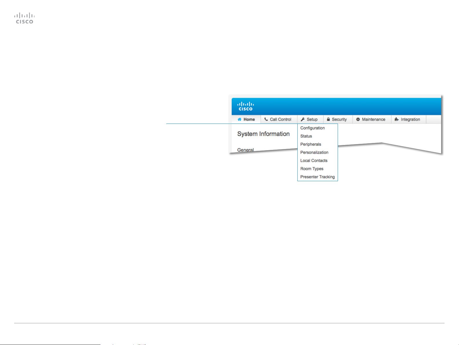
System Configuration page
When signed in, you can open the Configuration page from
the Setup menu.
You can access all configuration settings from this page. The
configurations described in the following chapter can be found
here.
To control the settings on your system, view the Status section.
You can find it under the Setup menu.
Read how to configure the system on the web interface on
page 13.
Getting Started Guide
Configuration sub-menu
You can open the
Configuration page from
the Setup menu
D15318.02 Video Systems Getting Star ted Guide CE8.1, APRIL 2016. Copyright © 2016 Cisco Systems, Inc. All rights reserved. 7
Page 8
Cisco TelePresence Video Systems
Introduction
User interfaces
Web interface
On-screen setup assistant
Appendices
Touch
User interfaces
TRC6 remote control
Getting Started Guide
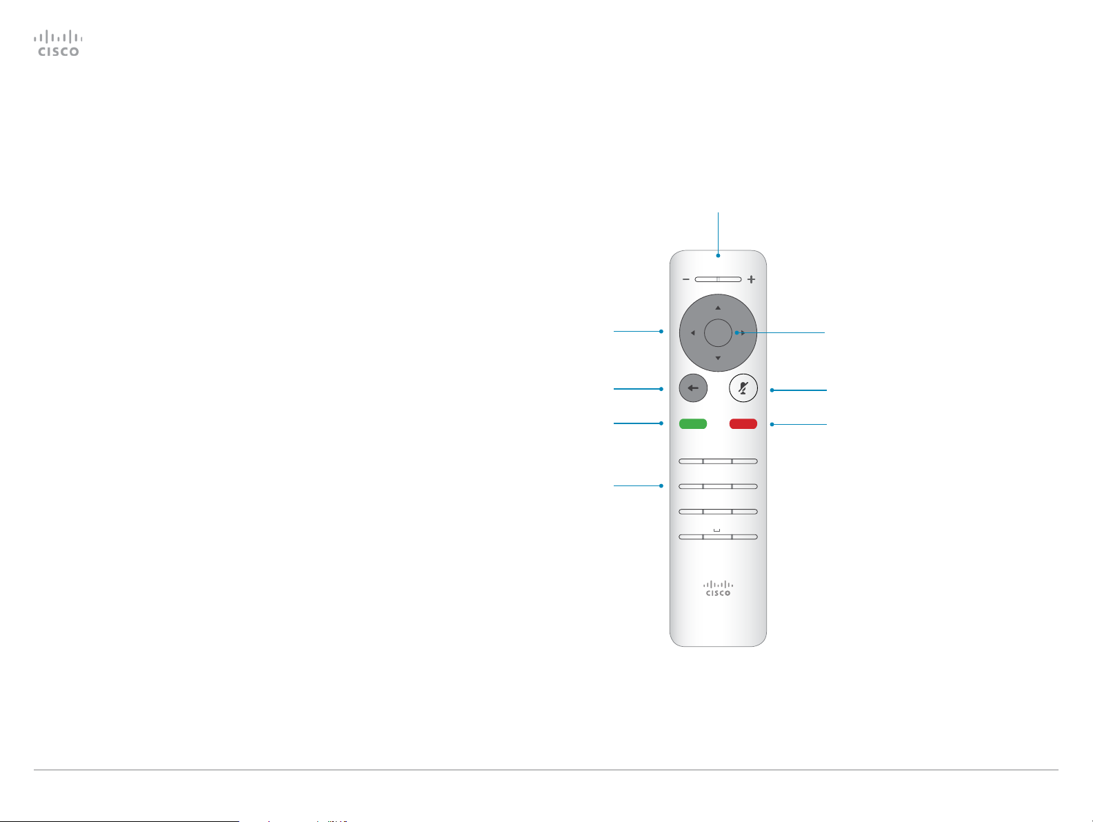
When you pick up the remote control, the system wakes up.
Use the Cursor controls to move about the screen and press
OK/Enter to open the selected menu field.
Use the Cancel key to exit a menu (and return to the Home
screen) undoing any changes. Use the Back key to go just one
step back.
Make sure the remote control has working batteries (2 x AAA
batter ies).
Field selector/
Cursor keys
Go back one step
Place call /
Accept incoming call
Keypad
Volume control and
Increase/Decrease control
1 2 3
.@
4 5 6
ghi jkl mno
7 8 9
pqrs tuv wxyz
*
defabc
#
0
OK/Enter
Microphone
mute/unmute
Reject incoming call /
End c all / Cancel /
Back to Home
screen (outside calls)
D15318.02 Video Systems Getting Star ted Guide CE8.1, APRIL 2016. Copyright © 2016 Cisco Systems, Inc. All rights reserved. 8
Page 9
Cisco TelePresence Video Systems
Introduction
User interfaces
Web interface
On-screen setup assistant
Appendices
Touch
User interfaces
On-screen menu when using a remote control
Getting Started Guide
Camera
Control
When you start the system for the first time, the Setup assistant
starts automatically.
Read how to configure the system with the on-screen setup
assistant on page 20.
Settings menu
After the initial set up, you can revisit the configurations and
more in the Settings menu:
• Language: Select a language for the user interface.
• Time zone: Select your local time zone.
•
Screen adjustment: Adjust display and system settings for
correct rendering of video and graphics.
•
Network connection: Change the IPv4 settings, if those
have not been configured by autoprovisioning or the
network. VLAN settings are also available.
•
Service activation: Change provisioning settings, if those
have not been configured by autoprovisioning.
•
Microphone check: Check that the microphone is working.
If you are using an external microphone, use this test to
adjust its location.
• Sound test
• Default camera preset: Set the default camera position for
future calls.
•
Presentation: Test presenting from your computer. You
need an HDMI or VGA cable for this.
•
Factory settings: Reset your video system to its factory
settings, and you lose your current registration. You cannot
undo a factory reset.
•
Extended logging: Helps diagnose network issues and
problems during call setup. While in this mode more information is stored in the log files. Extended logging uses
more of the system’s resources, and may cause it to
underperform. Only use extended logging mode when you
are troubleshooting an issue.
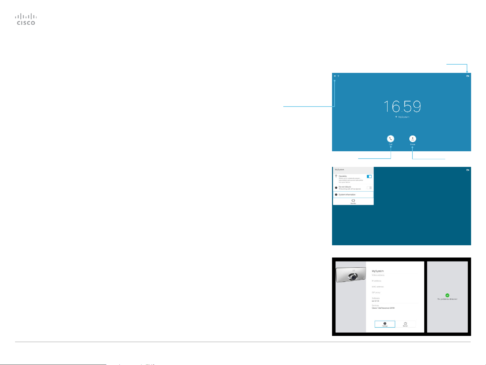
• Proximity
• Do not disturb
• System Information
• Standby
Place calls Share content
To access the Settings menu, navigate to
upper left corner of the screen and press OK
on the remote control. Then navigate down
to System Information and press OK again.
The System Information menu shows the
basic system information and potential
issues the system might have. You can also
restart the system from this page.
In addition this page provides access to
the Settings menu. These settings can
be protected with a PIN set from the web
interface.
D15318.02 Video Systems Getting Star ted Guide CE8.1, APRIL 2016. Copyright © 2016 Cisco Systems, Inc. All rights reserved. 9
Page 10
Cisco TelePresence Video Systems
Introduction
User interfaces
Web interface
On-screen setup assistant
Appendices
Touch
User interfaces
Getting Started Guide
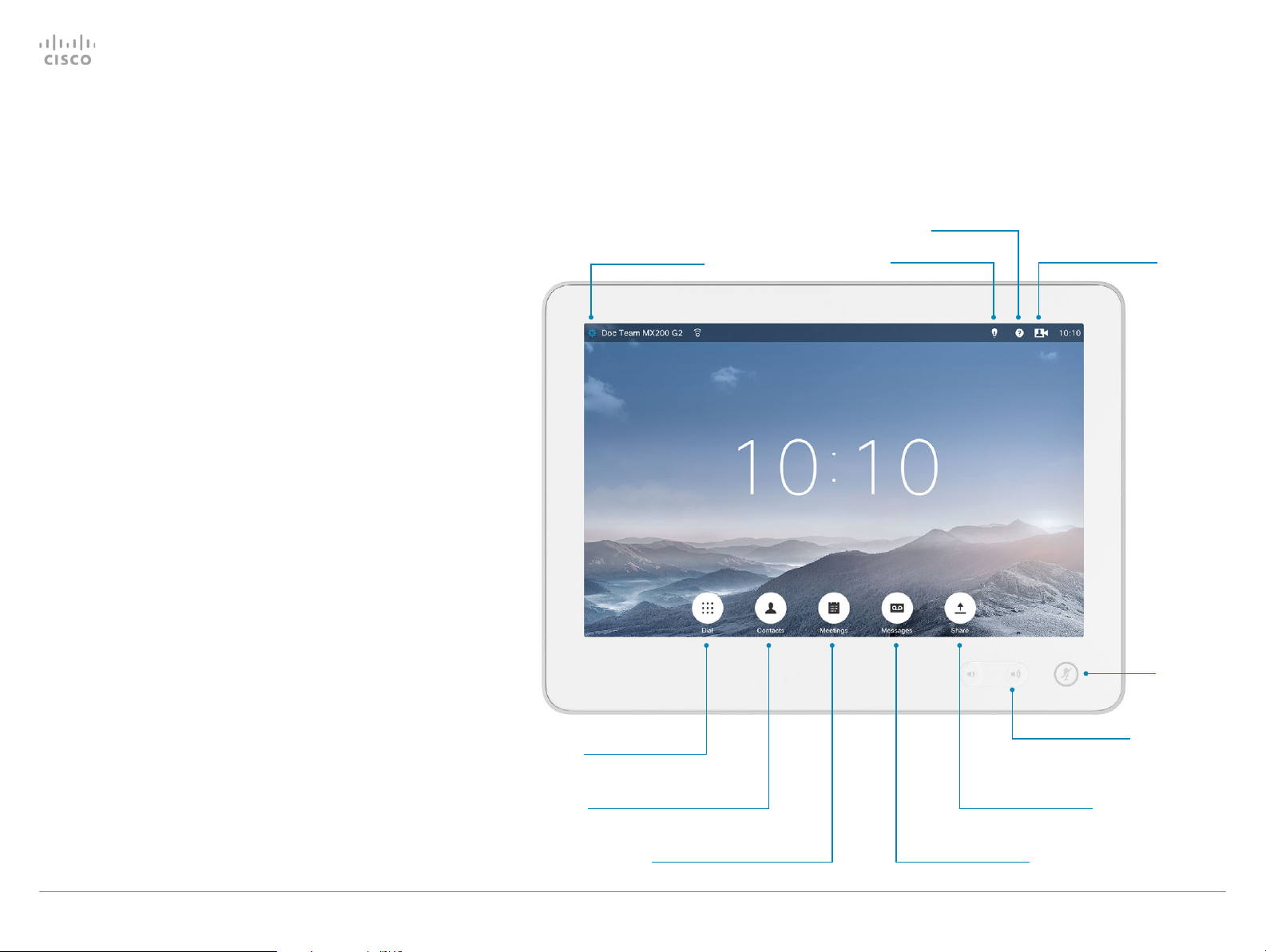
Touch controller
When you start the system for the first time, the Setup assistant
starts automatically.
The Touch controller, and its use, is described in full detail in
the user guide for your video conference system.
Not all settings are available on all products; therefore the
touch buttons shown below may or may not be present on
your system.
Here you can find:
• Proximity
• Do not disturb
• Settings menu
• Standby
Help desk
In-room controls
Control the camera
and adjust self view
D15318.02 Video Systems Getting Star ted Guide CE8.1, APRIL 2016. Copyright © 2016 Cisco Systems, Inc. All rights reserved. 10
Make a call using
the dial pad
Make a call from your
directory or call history Share content
See the list of upcoming
meetings Call your voice mail
Adjust volume
Mute your
microphone
Page 11

Cisco TelePresence Video Systems
Introduction
User interfaces
Web interface
On-screen setup assistant
Appendices
Touch
User interfaces
Getting Started Guide
The Touch controller Settings menu
To open the Settings menu, tap the system or user name in the
upper left corner and tap Settings.
System configuration
To enter the Administrator Settings menu, tap Administrator,
enter Username and Passphrase, and log in. A soft keyboard
appears when you tap the input fields. Tap Admin Settings.
The Administrator Settings menu is protected with the system
passphrase.
Read how to configure your system with a Touch controller
go to page 25.
You can set restrictions to users’ access to the settings
menu. This can be done on the web interface. Go to Setup
> Configuration > User Interface and set User Preferences to
Off. With this restriction, only System Information, Call Status,
Diagnostics and Restart are available for the users.
You can find a complete description of the Touch controller
menus in the user guide for your video conference system.
Not all settings are available on all products; therefore the menu
items shown to the right may or may not be present on your
system.
Settings
Rington e & Sound
Camera Control
Main Source Selection
Display
Language
System Information
Call Status
Diagnostics
Restart
Administrator
Back
Administrator Setti
Tracking
Date, Time & Location
Call Details
Provisioning
Pairing
IP & VLAN
Network Status
SIP
H323
Security
EMC Resilience
Reset
The Settings menu
• Ringtone & Sound: Select a ring tone, the ring tone volume and key tone.
• Camera Control: Set the whitebalance, exposure and backlight compensation.
• Main Source Selection: Select the main input source, e.g. camera control.
• Display: Select brightness, whitebalance and DVI mode for the main video display.
• Language: Select the language for the user interface.
• System Information: An overview of the system configurations.
•
Call Status: An overview of the call parameters when in call, e.g. protocols,
transmit and receive rates, packet loss.
• Diagnostics: Set additional system logging on.
• Restart: Restart the system.
• Administrator: See below.
The Administrator Settings menu
•
Tra c king: Choose tracking speed and set up snap-to-whiteboard feature
when you have a SpeakerTrack 60 camera.
• Date, Time & Location: Configure date and time settings.
• Call Details: Configure the default call rate and auto answer settings.
• Provisioning: Start the provisioning wizard.
•
Pairing: See information about the endpoint the Touch is paired to, and
unpair from that endpoint.
•
IP & VLAN: Configure the IP and VLAN settings. If the Touch controller
is connected via LAN, there are separate entries for the codec and the
Tou c h .
• Network Status - Codec: Current network status for the codec.
• Network Status - Touch: Current network status for the Touch controller.
• SIP: Configure the SIP settings.
• H323: Configure the H.323 settings.
• Security: See which certificates are installed on your system.
•
EMC Resilience: Change the Touch controller's resilience to electromag-
netic noise.
•
Reset: Complete a factory reset. This resets all of your settings. You
cannot undo a factory reset.
D15318.02 Video Systems Getting Star ted Guide CE8.1, APRIL 2016. Copyright © 2016 Cisco Systems, Inc. All rights reserved. 11
Page 12

Cisco TelePresence Video Systems
Introduction
User interfaces
Web interface
On-screen setup assistant
Appendices
Touch
Web interface
Getting Started Guide
Configuration:
Web interface
D15318.02 Video Systems Getting Star ted Guide CE8.1, APRIL 2016. Copyright © 2016 Cisco Systems, Inc. All rights reserved. 12
Chapter 3
Page 13

Cisco TelePresence Video Systems
Introduction
User interfaces
Web interface
On-screen setup assistant
Appendices
Touch
Web interface
Web interface
You have to use the Touch controller or the remote control for
the configurations, until you know your system's IP address.
The configurations described in this chapter can also be found
on the Touch controller under Administrator settings. You must
enter the administrator passphrase to access that page.
Find the IP address
If you have a Touch controller, tap the gearwheel in the upper
left corner and tap Settings. You can find the IPv4 address and/
or IPv6 address in the System Information section.
If you have a TRC6 remote control, navigate to the upper left
corner on the home screen and further to System Information.
Sign in to the web interface
Getting Started Guide
1. Open a web browser and enter the system’s IP address in
the address bar.
2. Enter your user name and passphrase and click Sign In.
The default user name is admin with no passphrase set.
If you are not able to connect to the system:
•
Make sure the system and computer are connected to the
same network.
• Make sure the system is switched on.
If the system has just been switched on, wait a few minutes to
allow the system to start up.
D15318.02 Video Systems Getting Star ted Guide CE8.1, APRIL 2016. Copyright © 2016 Cisco Systems, Inc. All rights reserved. 13
Page 14

Cisco TelePresence Video Systems
Introduction
User interfaces
Web interface
On-screen setup assistant
Appendices
Touch
Web interface
Provisioning set-up
Getting Started Guide
(When using a provisioning system)
If in doubt for any of the parameters below, contact your provisioning system provider.
See the administrator guide for your product, to find more
information about the individual provisioning settings.
Select provisioning infrastructure
1. Go to the Setup tab, and click Configuration.
2. Open the Provisioning settings from the left column.
3.
Select a provisioning infrastructure from the Mode drop
down list:
•
TMS – Cisco TelePresence Management System (Not available for SX10)
• VCS – Cisco Video Communication Server
• CUCM – Cisco Unified Communications Manager
•
Auto - The system starts provisioning by first tr ying VCS,
then TMS and finally CUCM.
• Edge - CUCM via Expressway
If you select Off, all configurations must be set manually.
Set the required provisioning parameters
Which parameters to set depend on which infrastructure was selected.
TMS
1.
It may be required to authenticate the video system with
Cisco TMS. If so, enter LoginName and Password in the
respective input fields.
2.
Enter the IP address or DNS name of the Cisco TMS server
in the Address input field under the ExternalManager
heading.*
3.
Enter the Path to the provisioning ser vice in the corresponding input field.
VCS
1.
It may be required to authenticate the video system with
the Cisco VCS. If so, enter LoginName and Password in the
respective input fields.
2.
Enter the IP address or DNS name of the Cisco VCS in the
Address input field under the ExternalManager heading.*
3.
Enter the SIP Domain for the Cisco VCS in the corresponding input field.
Have a look at the Cisco VCS provisioning appendix for more
information about VCS provisioning.
Unified Communications Manager
Enter the IP address or DNS name of the CUCM provisioning
server in the Address input field under the ExternalManager
heading.*
You can find more details about setting up CUCM provisioning
in the Administering CE endpoints on CUCM guide.
CUCM via Expressway
Upon ordering the CUCM via Expressway service, you have
received a username, password, and domain name.
In some cases, you must manually enter the Expressway
address. Enter the address you have received upon ordering
in the Address input field under the ExternalManager heading.
1. Enter the username in the LoginName input field.
2. Enter the password in the Password input field.
3.
Enter the domain name in the Domain input field under the
ExternalManager heading.
If you are changing a value setting,
you have to always click save to confirm the change.
D15318.02 Video Systems Getting Star ted Guide CE8.1, APRIL 2016. Copyright © 2016 Cisco Systems, Inc. All rights reserved. 14
* The DHC P server can be set up to provide the External Manager address
automatically (Option 242 for TMS; Option 150 for UCM). Any input set up
here overrides the setting provided by DHCP.
Page 15

Cisco TelePresence Video Systems
Introduction
User interfaces
Web interface
On-screen setup assistant
Appendices
Touch
Web interface
IP settings
Getting Started Guide
(When not set by a provisioning system)
Your video conference system supports IP version 4 (IPv4),
IP version 6 (IPv6) and Dual, which is the default setting. In all
three cases, the IP parameters can be assigned automatically
by the network, or you can set everything manually. When set
to Dual, the network interface can operate on both IP versions,
and have both an IPv4 and an IPv6 address.
If you wish to set the parameters manually, contact your
network administrator to obtain the required parameters.
If you choose to set the IP settings manually while using the
Dual mode, you have to set both the IPv4 and the IPv6 settings.
Start from step 2 in the instructions.
If your system is provisioned automatically, these IP settings
may be overridden by the provisioning system.
If an IPv4 or IPv6 address is already assigned to the system,
you can find it on the System Information page. Go to the Setup
tab and choose Status and Network.
NOTE: It is not recommended to manually change the IP
address using the web interface, or remotely paired Touch
controller.
To set or change the IPv4 settings
Go to the Setup tab and click Configuration.
1. Choose IP version
Click the Network settings in the left sidebar. Choose IPv4
from the IPStack drop down list.
2. Choose automatic or manual IP assignment
Scroll down the page to the IPv4 section and choose DHCP
from the Assignment drop down list, if you want automatic
IP assignment; or Static, if you wish to set the IP address
manually.
3. If you wish to set IP Assignment manually
In the IPv4 section, enter the Address, Gateway and
SubnetMask in the corresponding input fields.
Scroll up to the DNS section and enter the DNS server
address in the Server 1 Address input field.
To set or change the IPv6 settings
Go to the Setup tab and click Configuration.
1. Choose IP version
Click the Network settings in the left sidebar. Choose IPv6
from the IPStack drop down list.
2. Choose automatic or manual IP assignment
Scroll down the page to the IPv6 section and choose
DHCPv6, Autoconf or Static from the Assignment drop
down list according to your network requirements.*
3. If IP Assignment is Static: Set the IP addresses
Enter the system IP address in the Address input field.
Optional: Enter the gateway address in the Gateway input
field.
4. If IP Assignment is Static or Autoconf: DHCPOptions
Choose On or Off from the DHCPOptions drop down list
according to your network requirements.**
5. If DHCPOptions is Off: Configure DNS and NTP
Scroll up to the DNS section, and enter the DNS server
address in the Server 1 Address input field.
Open the NetworkServices settings from the left sidebar,
and scroll down to the NTP section. Enter the NTP server
address in the Address input field. Set Mode to Auto.
* IP Assignment:
DHCPv6: All IP v6 addresses, including options like the DNS and NTP
server addresses, are obtained automatically from a DHCP v6 ser ver.
Autoconf: The system and gateway IP addresses will be assigned
If you are changing a value setting,
you have to always click save to confirm the change.
D15318.02 Video Systems Getting Star ted Guide CE8.1, APRIL 2016. Copyright © 2016 Cisco Systems, Inc. All rights reserved. 15
automatically. The options, e.g. NTP and DNS server addresses, must be
set/assigned according to the DHCP Options setting. **
Static: The system and gateway IP addresses must be configured
manually. The options, e.g. NTP and DNS server addresses, must be set /
assigned according to the DHCP Options setting. **
** DHCP Options:
On: The IP parameters, like the DNS and NTP server addresses, will be
obtained automatically from a DHCPv6 ser ver.
Off: The IP parameters, like the DNS and NTP server addres ses, must be
set manually.
Page 16

Cisco TelePresence Video Systems
Introduction
User interfaces
Web interface
On-screen setup assistant
Appendices
Touch
Web interface
Configure H.323 and SIP
Getting Started Guide
(When not set by a provisioning system)
To get online and ready to place and receive calls, your system
must be set up properly. Your system uses either the H.323
protocol or the SIP protocol for video calls.
The diagnostics on your system will indicate if there is a
problem with H.323 or SIP registering.
If you wish to change the other H.323 or SIP settings, see the
administrator guide for your product.
For networks administered through Cisco TMS (Cisco
TelePresence Management Suite), your Cisco TMS administrator will help you to get online.
You can find information about administering through Cisco
UCM in the Administering CE endpoints on CUCM guide.
NOTE: H.323 is not available for the SX10.
H.323
If in doubt for any of the parameters below, contact your system
administrator or your service provider.
1. Go to the Setup tab, and select Configuration.
2. Open the H323 settings from the left sidebar.
3.
Under the H323Alias heading enter the E164 and the ID
number in the corresponding input fields.
4.
Enter the Gatekeeper Address in the corresponding input
field.
5.
If the H.323 gatekeeper requires authentication, and you
want your system to authenticate itself to the gatekeeper,
go to the Authentication subheading and select On in
the Mode drop down list. Then enter the LoginName and
Password in the corresponding input fields.
Otherwise, select Off in the Mode drop down list.
SIP
If in doubt for any of the parameters below, contact your system
administrator or your service provider.
1. Go to the Setup tab, and select Configuration.
2. Open the SIP settings from the left sidebar.
3.
Enter the SIP URI in the URI input field, and optionally a
display name in the DisplayName input field.
4.
Select the preferred transport protocol from the
DefaultTransport drop down list. If you select Auto, the
system first tries to connect using Tls, then TCP, and finally
U D P.
5.
Select a proxy type in the Ty p e drop down list. The default
type is Standard. You can use Cisco when registering to
CUCM.
6. Enter the Proxy 1 Address in the corresponding input field
7.
If the SIP proxy requires authentication, you must enter a
login name and password to authenticate your system. Go
to the Authentication heading and enter the LoginName and
Password in the corresponding input fields.
If you are changing a value setting,
you have to always click save to confirm the change.
D15318.02 Video Systems Getting Star ted Guide CE8.1, APRIL 2016. Copyright © 2016 Cisco Systems, Inc. All rights reserved. 16
Page 17

Cisco TelePresence Video Systems
Introduction
User interfaces
Web interface
On-screen setup assistant
Appendices
Touch
Web interface
Date, time and location
Getting Started Guide
(When not set by a provisioning system)
We recommend you check that the date and time settings
are correct when you set up your video conference system.
The system uses this information for example to time stamp
messages transmitted to gatekeepers and other network
elements.
1.
Go to Setup tab and select Configuration. Open the Time
settings from the left column.
2.
Select your preferred date format in the DateFormat drop
down list.
3.
Select your preferred time format in the TimeFormat drop
down list.
4. Select your time zone in the Zone drop down list.
5. Open the NetworkServices settings from the left side bar.
6.
Under the NTP section select Auto, Manual or Off in the
Mode drop down list.*
a.
If you select Manual, enter the NTP server address in
the Address input field.
b.
If you select Off, you have to enter the time and date
manually using either the Touch controller ( Settings
> Administrator > Date, Time & Location) or on the
command line interface (xCommand Time DateTime
Set) .
7.
To verify the time settings, go to Setup and click Status.
Open Time status from the left side bar.
* NTP mode:
Auto: The time is regularly updated using an NTP server. The NTP ser ver
If you are changing a value setting,
you have to always click save to confirm the change.
D15318.02 Video Systems Getting Star ted Guide CE8.1, APRIL 2016. Copyright © 2016 Cisco Systems, Inc. All rights reserved. 17
addres s is automatically obtained from the network (DHCP).
Manual: The time is regularly updated using an NTP server. You must
manually enter the NTP server address.
Off: You must set the time manually. The time is not updated automatically.
Page 18

Cisco TelePresence Video Systems
Introduction
User interfaces
Web interface
On-screen setup assistant
Appendices
Touch
Web interface
Passphrase
Getting Started Guide
You need a user name and a passphrase to sign in to the web
and command line interfaces of your system. You also need the
system passphrase to access the administrator and advanced
settings on the Touch controller.
The video conference system is delivered with a default user
account with the user name admin and no passphrase set. This
user has full access rights to the system.
NOTE: Initially, no passphrase is set for the default admin u s er.
It is mandatory to set a passphrase for any user with ADMIN
rights in order to restrict access to system configuration. This
includes the default admin user.
A warning, saying that the system passphrase is not set, is
shown on screen until you set a passphrase.
Make sure to keep a copy of the passphrase in a safe place.
You have to factory reset the unit, if you have forgotten the
passphrase.
Set the system/codec passphrase
NOTE: We strongly recommend that you set a passphrase for
the admin user to restrict access to system configuration.
1.
Click your user name in the upper right corner, and select
Change passphrase.
2.
Enter the Current passphrase, the New passphrase, and
repeat the new passphrase in the corresponding input
fields.
The passphrase format is a string with 0–64 characters.
If a passphrase is not currently set, use a blank Current
passphrase.
3. Click Change passphrase.
D15318.02 Video Systems Getting Star ted Guide CE8.1, APRIL 2016. Copyright © 2016 Cisco Systems, Inc. All rights reserved. 18
Page 19

Cisco TelePresence Video Systems
Introduction
User interfaces
Web interface
On-screen setup assistant
Appendices
Touch
On-screen setup assistant
Getting Started Guide
Configuration:
On-screen setup assistant
D15318.02 Video Systems Getting Star ted Guide CE8.1, APRIL 2016. Copyright © 2016 Cisco Systems, Inc. All rights reserved. 19
Chapter 4
Page 20
Cisco TelePresence Video Systems
Introduction
User interfaces
Web interface
On-screen setup assistant
Appendices
Touch
On-screen setup assistant
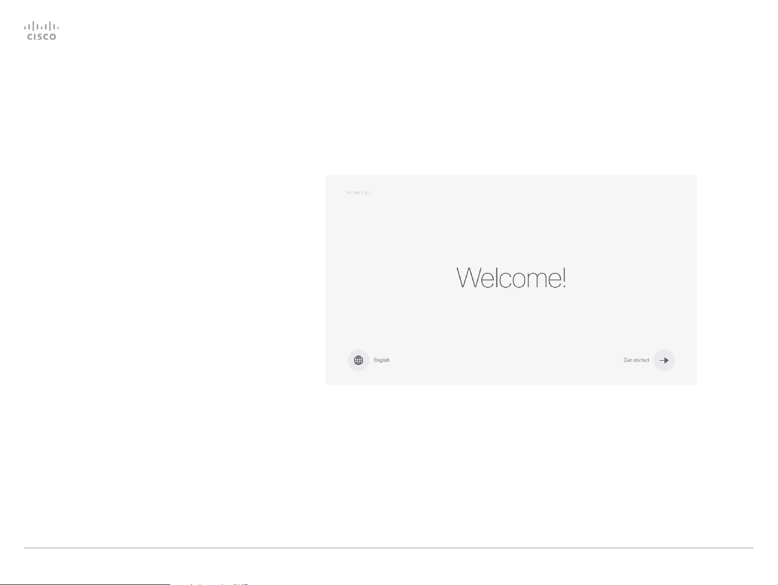
On-screen setup assistant when using a remote control
The on-screen setup assistant is available for SX10 and SX20
when you are using a remote control. When you start the
system for the first time, the setup assistant starts automatically.
To be able to make calls your system needs an IP address
and it needs to be registered to a service. If your system is
automatically provisioned, the IP and provisioning settings
presented in this chapter are automatically configured.
Access the settings after initial setup
Navigate to the gearwheel icon in the upper left corner on the
home screen and press OK on the remote control.
Navigate to System Information > Settings. Select the setting
you wish to change.
No image on screen
Getting Started Guide
If the menu doesn't show up on the screen:
•
Make sure the monitor is connected and has been
switched on.
•
Make sure that the correct input is selected on the monitor.
• Make sure the remote control has batteries installed.
• Make sure the system is switched on.
If the system has just been switched on, wait a few minutes to
allow the system to start up.
If you still can't see the on-screen menu, make sure the
monitor cable is connected to the video output connector. If in
doubt, see the installation guide for your product.
NOTE: This guide doesn't cover information on Cisco Spark
registered systems. For more information on Cisco Spark
room systems, visit:
https://help.webex.com/community/cisco-cloud-collab-mgmt
D15318.02 Video Systems Getting Star ted Guide CE8.1, APRIL 2016. Copyright © 2016 Cisco Systems, Inc. All rights reserved. 20
Page 21
Cisco TelePresence Video Systems
Introduction
User interfaces
Web interface
On-screen setup assistant
Appendices
Touch
On-screen setup assistant
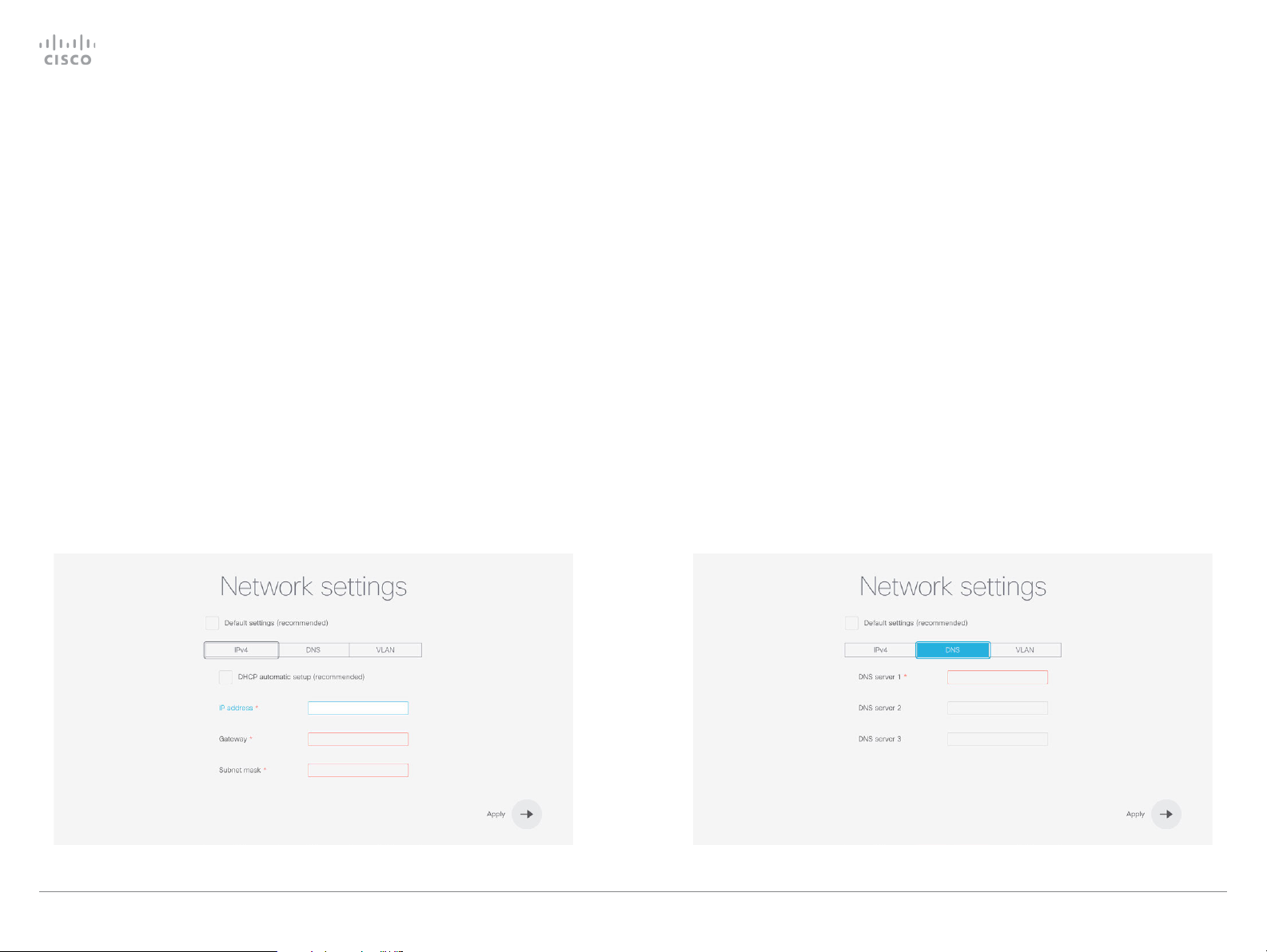
IP settings
(When not set by a provisioning system)
The IP parameters are assigned automatically by the network,
or you can set everything manually. If your system is provisioned automatically, manual IP settings may be overridden by
the provisioning system.
If you want to set the parameters manually, contact your
network administrator to obtain the required parameters.
If an IPv4 address is already assigned to the system, you will
find it under System Information: Navigate to the gearwheel
icon in the upper left corner on the home screen and select
System Information.
If you wish to change the IP settings from the default dual
stack setting to either IPv4 or IPv6, this can be done on the
web interface. To set up IPv6 settings manually, use the Touch
controller or the web interface.
NOTE: When you start up the SX10 or SX20 for the first time,
the Setup assistant starts automatically. The setup wizard skips
the IP settings, if those are already set up by the network.
1.
Navigate to the gearwheel icon on the home screen, and
select System Information > Settings. Navigate to Network
Connection and select Network Settings.
2.
Uncheck Default settings and DHCP automatic setup, if you
want to set the IP address manually.
3.
Enter the IP Address, Subnet Mask and Gateway address.
A soft keyboard appears when you select an input field.
Select OK to confirm the change.
4.
Navigate to the DNS section and enter the DNS server
address in the DNS Server 1 input field.
5. Select Apply to save the changes.
Getting Started Guide
D15318.02 Video Systems Getting Star ted Guide CE8.1, APRIL 2016. Copyright © 2016 Cisco Systems, Inc. All rights reserved. 21
Page 22
Cisco TelePresence Video Systems
Introduction
User interfaces
Web interface
On-screen setup assistant
Appendices
Touch
On-screen setup assistant
Provisioning
(When using a provisioning system)
If your system is automatically provisioned, the IP and provisioning settings are automatically configured and the setup
assistant skips these steps.
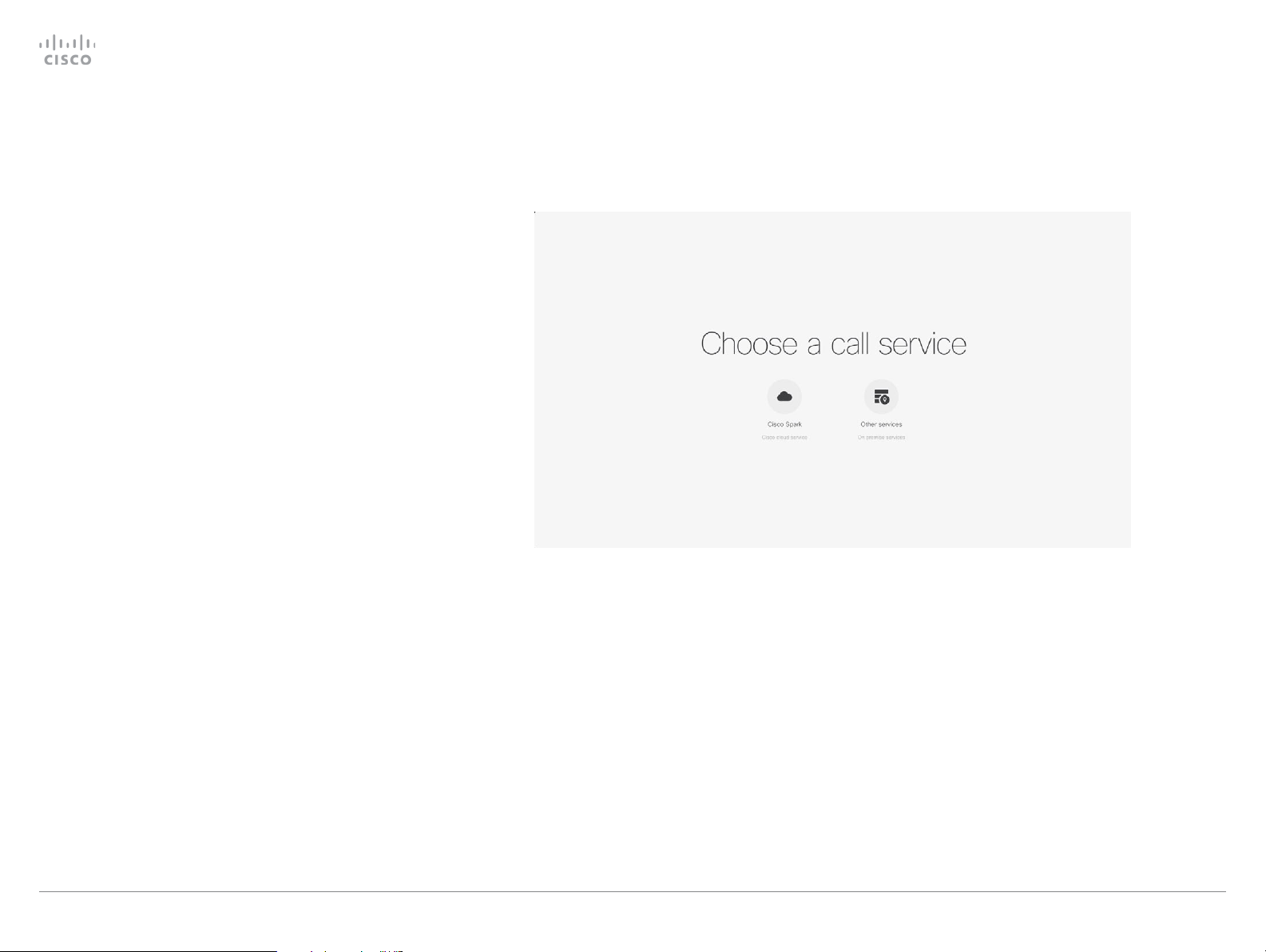
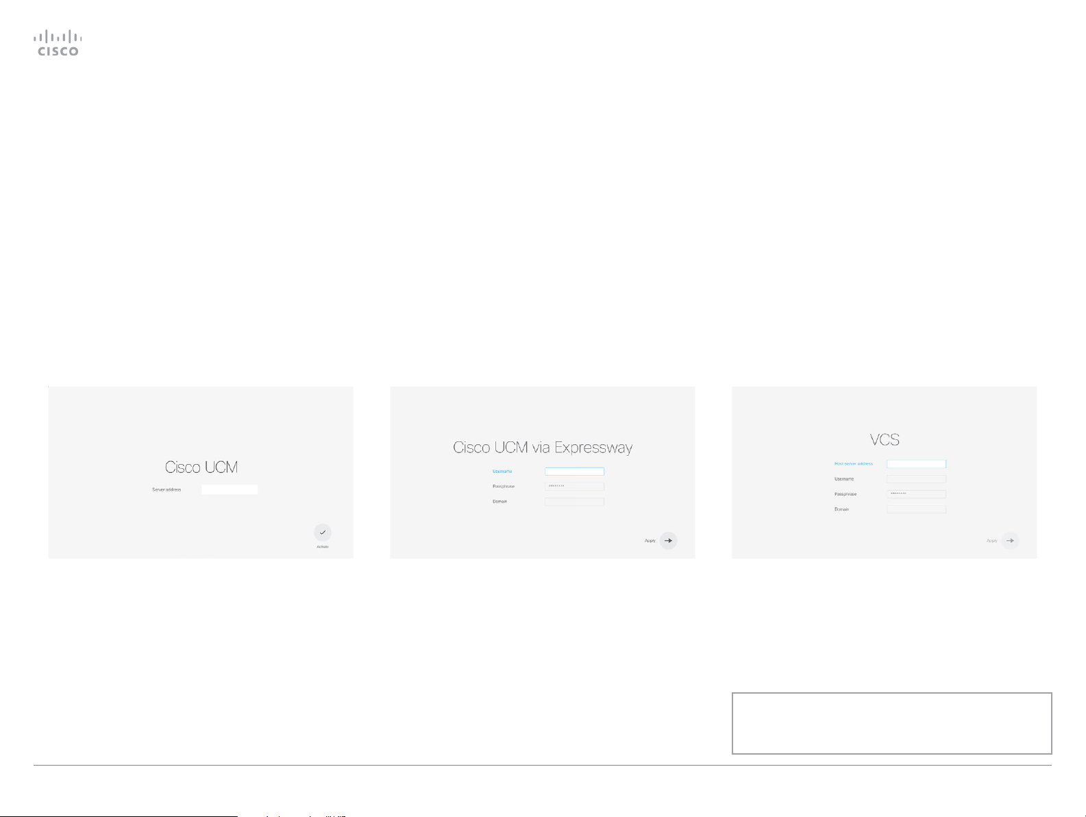
Choose provisioning infrastructure
Choose one of the following supported on premise provisioning systems:
• Cisco UCM (Cisco Unified Communications Manager)
• Cisco UCM via Expressway
• VCS (Video Communication Server)
If you choose manual setup, you must register the system on
the system's web interface. Manual setup is only available on
the first time setup assistant.
If you wish to revisit these settings after the initial setup,
navigate to the gearwheel icon on the home screen, and select
System Information > Settings > Service activation. Select
Change service.
NOTE: When you start up the SX10 or SX20 for the first time,
the setup assistant starts automatically.
Getting Started Guide
D15318.02 Video Systems Getting Star ted Guide CE8.1, APRIL 2016. Copyright © 2016 Cisco Systems, Inc. All rights reserved. 22
Page 23
Cisco TelePresence Video Systems
Introduction
User interfaces
Web interface
On-screen setup assistant
Appendices
Touch
On-screen setup assistant
Getting Started Guide
Cisco Unified Communications Manager
Contact your CUCM administrator to get the information
needed.
Enter IP address or DNS name in the Host server address field,
and select OK to confirm the change*.
You can find more details about setting up CUCM provisioning
in the Administering CE endpoints on CUCM guide.
CUCM via Expressway
Contact your CUCM administrator to get the information
needed.
Enter Username, Passphrase and Domain in the corresponding
input fields. Always select OK to confirm the changes. Select
Apply to save.
In some cases, you must manually enter the Expressway
address. Select Manually override Expressway address, and
enter the address you have received upon ordering in the Host
Server Address field.
VCS
Contact your VCS provider to get the information needed.
1.
Enter IP address or DNS name of the Cisco VCS in the
Host server address and select OK to confirm the change.
2.
Enter the Username, and Passphrase, if required, for
authenticating the video system with the provisioning
server. Select OK to confirm the change
3. Enter SIP Domain and select OK to confirm the change.
4. Select Apply to save the changes.
Have a look at the Cisco VCS provisioning appendix for more
information on VCS provisioning.
* The DHC P server can be set up to prov ide the Host server address
automatically (DHCP Option 150). Any input set up here overrides the
setting provided by DHCP.
D15318.02 Video Systems Getting Star ted Guide CE8.1, APRIL 2016. Copyright © 2016 Cisco Systems, Inc. All rights reserved. 23
To check that the SX10 is registered: Navigate to the
gearwheel icon in the upper left corner of the home
screen and select System Information.
Page 24

Cisco TelePresence Video Systems
Introduction
User interfaces
Web interface
On-screen setup assistant
Appendices
Touch
Touc h
Getting Started Guide
Configuration:
Touch controller
D15318.02 Video Systems Getting Star ted Guide CE8.1, APRIL 2016. Copyright © 2016 Cisco Systems, Inc. All rights reserved. 24
Chapter 4
Page 25
Cisco TelePresence Video Systems
Introduction
User interfaces
Web interface
On-screen setup assistant
Appendices
Touch
Touc h
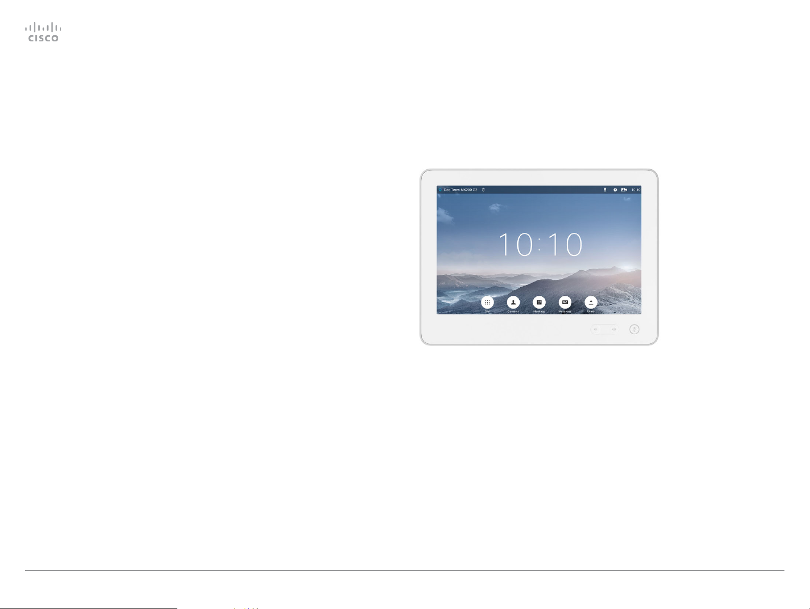
Touch controller
Wake up the system
If there is no menu displayed on the Touch controller, tap the
display to wake up the system.
If the system doesn't wake up:
•
Make sure the Touch controller is connected to the main
unit.
•
Make sure the main unit is connected to power and
switched on.
If the system has just been switched on, wait a few minutes
to allow the system to start up.
For further instructions, read the installation guide and the
administration for your product.
For an overview of Touch controller features and use, see
How to use the Touch controller.
Getting Started Guide
D15318.02 Video Systems Getting Star ted Guide CE8.1, APRIL 2016. Copyright © 2016 Cisco Systems, Inc. All rights reserved. 25
Page 26

Cisco TelePresence Video Systems
Introduction
User interfaces
Web interface
On-screen setup assistant
Appendices
Touch
Touc h
Provisioning set-up
Getting Started Guide
(When using a provisioning system)
Start the Provisioning Wizard
Tap the user name in the upper left corner, and tap Settings.
Tap Administrator > Provisioning and then Start.
NOTE: When you start up a system with a Touch controller
for the first time, the Provisioning Wizard starts automatically.
Choose provisioning infrastructure
Choose one of the following supported provisioning systems:
• Cisco UCM (Unified Communications Manager)
• Cisco UCM via Expressway
• Cisco VCS (Video Communication Server)
Tap Register to proceed.
Enter required parameters
Enter the parameters required for the chosen provisioning
infrastructure. Then tap Register to complete the procedure.
Cisco UCM
Contact your UCM provider to get the IP address or DNS
name of the Cisco UCM (External Manager).*
You can find more details about setting up Cisco UCM provisioning in the Administering CE endpoints on CUCM guide
Cisco UCM via Expressway
In some cases, you must manually enter the Expressway
address. Select Manually override Expressway address, and
enter the address you have received upon ordering in the
External Manager field.
Cisco VCS
Contact your VCS provider to get the IP address or DNS
name of the Cisco VCS (External Manager) and the SIP
Domain.*
If required, set the Username and Passphrase for authenticating the video system with the provisioning ser ver.
Have a look at the Cisco VCS provisioning appendix for
more information on VCS provisioning.
Upon ordering this service, you have received a Username,
Domain and Passphrase. Enter those in the corresponding
input fields.
D15318.02 Video Systems Getting Star ted Guide CE8.1, APRIL 2016. Copyright © 2016 Cisco Systems, Inc. All rights reserved. 26
* The DHC P server can be set up to provide the Exter nal Manager address
automaticall y (DHCP Option 150). Any input set up here overrides the
setting provided by DHCP.
Page 27

Cisco TelePresence Video Systems
Introduction
User interfaces
Web interface
On-screen setup assistant
Appendices
Touch
Touc h
IP settings
Getting Started Guide
(When not set by a provisioning system)
On the Touch controller, you can select the IP settings for the
upcoming calls. If you wish to change the IP settings from the
default dual stack setting to either IPv4 or IPv6, you can do
that on the web interface.
The system’s IP configuration is by default set to dual stack.
This means that the network interface can operate on both
IP versions, and has both an IPv4 and an IPv6 address at
the same time.
The IP parameters can be assigned automatically by the
network, or you can set everything manually. If you want to
set the parameters manually, please contact your network
administrator to obtain the required parameters.
If your system is provisioned automatically, these IP settings
may be overridden by the provisioning system.
To go back to default IP settings tap the user name in the
upper left corner and tap Settings > Administrator > IP &
VLAN and Default.
If an IPv4 or IPv6 address is already assigned to the system,
you will find it in the NETWORK section on the System
Information page: Tap the user name in the upper left corner
and tap Settings > System Information.
Set or change the IPv4 settings
1. Choose IP version
Tap the user name in the upper left corner and tap
Settings > Administrator > IP & VLAN (Codec). Then
tap Advanced. Check the IPv4 box, if it has not been
checked.
2. Choose automatic or manual IP assignment
Tap the arrow ( ) beside IPv4. Tap DHCP in the IP
Assignment section, if you want automatic IP assignment;
or Static if you want to set the IP addresses manually.
3. If IP Assignment is Static: Set the IP addresses
Enter the IP Address, Subnet Mask, Gateway, and DNS
Server address. A soft keyboard appears when you tap
an input field.
4. Save the settings
Tap Save to confirm the changes, or Undo to leave
without saving.
5. Return to the main menu
Tap Exit to return to the home menu.
Set or change the IPv6 settings
1. Choose IP version
Tap the user name in the upper left corner and tap
Settings > Administrator > IP & VLAN (Codec). Then
tap Advanced. Check the IPv6 box, if it has not been
checked.
2. Choose automatic or manual IP assignment
Tap the arrow ( ) beside IPv6. Choose DHCP, Auto
or Off in the IP Assignment section according to your
network requirements.*
3. If IP Assignment is Static: Set the IP addresses
Enter the IP Address and Gateway. A soft keyboard
appears when you tap an input field.
4. If IP Assignment is Static or Auto: Set DHCP Options
Tap On or Off in the DHCP Options section according to
your network requirements.**
If DHCP Options are switched Off, you must set the
DNS and NTP server addresses on the web interface
(see “Configure DNS and NTP” on page 15).
5. Save the settings
Tap Save to confirm the changes, or Undo to leave
without saving.
* IP Assignment:
DHCP: All IP v6 addresses, including options like the DNS and NTP
server addresses, are obtained automatically from a DHCP v6 ser ver.
Auto: The system and gateway IP addresses will be as signed
automatically. The options, e.g. NTP and DNS server addresses, must
be set/assigned according to the DHCP Options setting. **
Static: The system and gateway IP addresses must be configured
manually. The options, e.g. NTP and DNS server addresses, must be
set/assigned according to the DHCP Options setting. **
D15318.02 Video Systems Getting Star ted Guide CE8.1, APRIL 2016. Copyright © 2016 Cisco Systems, Inc. All rights reserved. 27
6. Return to the main menu
Tap Exit to return to the home menu.
** DHCP Options:
On: The IP parameters, like the DNS and NTP server addresses, will be
obtained automatically from a DHCPv6 ser ver.
Off: The IP parameters, like the DNS and NTP server addres ses, must
be set manually.
Page 28

Cisco TelePresence Video Systems
Introduction
User interfaces
Web interface
On-screen setup assistant
Appendices
Touch
Touc h
Configure H.323 and SIP
Getting Started Guide
(When not set by a provisioning system)
To get online and ready to place and receive calls, your
system must be set up properly. Your system uses either the
H.323 protocol or the SIP protocol for video calls.
NOTE: Contact your system administrator, or service provider,
for information about the network settings.
For networks administered through Cisco TMS (TelePresence
Management Suite), your Cisco TMS administrator will help
you to get online.
You can find information about administering through Cisco
UCM in the Administering CE endpoints on CUCM guide.
H.323
If in doubt about any of the parameters below, contact your
system administrator or your service provider.
1.
Tap the gearwheel icon in the upper left corner and tap
Settings > Administrator > H323.
2.
Enter the H323 Number and H323 Id in their respective
input fields.
3.
Enter the Gatekeeper Address in the corresponding input
field.
4. If the H.323 gatekeeper requires authentication and you
want your system to authenticate itself to the gatekeeper,
tap ON in the Authentication Mode section and enter the
Login Name and Password in their respective input fields.
Otherwise, tap OFF.
5.
Tap Save to confirm the changes, or Undo to leave
without saving.
6.
Review the System Information page and verify the H323
settings.
If you have successfully registered to the Gatekeeper,
the Status is shown as Registered in the H323 section.
7. Tap Exit to return to the home menu.
SIP
If in doubt about any of the parameters below, contact your
system administrator or your service provider.
1.
Tap the gearwheel icon in the upper left corner and tap
Settings > Administrator > SIP.
2. Enter the SIP URI in the URI input field.
3.
Tap the preferred transport protocol in the Default
Transport section. If you select Auto, the system tries
first to connect using TLS, then TCP, and finally UDP.
4.
Select a Proxy Type by tapping - or +. The default type is
Standard. You can use Cisco when registering to CUCM.
5.
Enter the Proxy Address in the corresponding input field.
6.
If the SIP proxy server requires authentication, you must
enter the Login Name and Password in their respective
input fields to authenticate your system.
7.
Tap Save to confirm the changes, or Undo to leave
without saving.
8.
Review the System Information page and verify the SIP
settings.
If you have successfully registered to a SIP ser ver, the
Status is shown as Registered in the SIP section.
D15318.02 Video Systems Getting Star ted Guide CE8.1, APRIL 2016. Copyright © 2016 Cisco Systems, Inc. All rights reserved. 28
9. Tap Exit to return to the home menu.
Page 29

Cisco TelePresence Video Systems
Introduction
User interfaces
Web interface
On-screen setup assistant
Appendices
Touch
Touc h
Date, time and location
Getting Started Guide
(When not set by a provisioning system)
We recommend you check that the date and time settings
are correct when you set up your video conference system.
The system uses this information for example to time stamp
messages transmitted to gatekeepers and other network
elements.
You can find the time in the top right corner of the Touch
controller display.
1.
Tap the user name in the upper left corner and tap
Settings > Administrator > Date, Time & Location.
2. Tap 24h or 12h to select the Time Format you prefer.
3. Tap dd.mm.yy, mm .dd .y y or yy.mm.dd to select the Date
Format you prefer.
4.
Select the Time Zone Area and Time Zone Location for
your system. Step through the list of available zones by
tapping - or + .
5.
Set Date & Time Mode to Auto if you want time and date
to be automatically updated; otherwise, select Manual.
a.
If you select Manual, enter the correct value for
Hour, Minute, Yea r, Month, and Day. Tap - and + to
decrease or increase a value.
b.
If you select Auto, the NTP server address can be
automatically obtained from the network (set the
NTP Mode to Auto) or you can enter the NTP Server
address yourself (set NTP Mode to Manual).
6.
Tap Save to confirm the changes, or Undo to leave
without saving.
7. Tap Exit to return to the home menu.
D15318.02 Video Systems Getting Star ted Guide CE8.1, APRIL 2016. Copyright © 2016 Cisco Systems, Inc. All rights reserved. 29
Page 30

Cisco TelePresence Video Systems
Introduction
User interfaces
Web interface
On-screen setup assistant
Appendices
Touch
Appendices
Getting Started Guide
Appendices
D15318.02 Video Systems Getting Star ted Guide CE8.1, APRIL 2016. Copyright © 2016 Cisco Systems, Inc. All rights reserved. 30
Page 31

Cisco TelePresence Video Systems
Introduction
User interfaces
Web interface
On-screen setup assistant
Appendices
Touch
Appendices
Cisco VCS provisioning
Getting Started Guide
When using the Cisco VCS (Video Communication Server)
provisioning, a template containing all the settings that can be
provisioned must be uploaded to Cisco TMS (TelePresence
Management System). This is called the Cisco TMS provision-
ing configuration template.
All the advanced settings for your video system are included
in this template. All settings except SystemUnit Name and SIP
Profile [1..1] URI can be automatically provisioned to the video
system.
The advanced settings are described in the administrator guide
for your video system.
Read the Cisco TMS Provisioning Deployment Guide to find
out how to upload the file to Cisco TMS, and how to set
the desired values for the parameters to be provisioned. If
not set by Cisco TMS, the default values are used. Go to:
http://www.cisco.com/c/en/us/support/conferencing/
telepresence-management-suite-tms/products-installationand-configuration-guides-list.html
Download the provisioning configuration
template
You can download the templates here:
MX Series:MX Series Release Notes
SX Series:SX Series Release Notes
For each software release there is one provisioning configuration template for every video system model. Make sure to
download the correct file.
D15318.02 Video Systems Getting Star ted Guide CE8.1, APRIL 2016. Copyright © 2016 Cisco Systems, Inc. All rights reserved. 31
Page 32

Cisco TelePresence Video Systems
Introduction
User interfaces
Web interface
On-screen setup assistant
Appendices
Touch
Appendices
User documentation on the Cisco web site
Getting Started Guide
User documentation for the Cisco TelePresence
products is available at
http://www.cisco.com/go/telepresence/docs
Choose a product category in the right pane until you find
the correct product. This is the path you have to follow:
Collaboration Room Endpoints >
Cisco TelePresence MX Series
TelePresence Integration Solutions >
Cisco TelePresence SX Series
Alternatively, use the following short-link to find the
documentation:
http://www.cisco.com/go/mx-docs
http://www.cisco.com/go/sx-docs
The documents are organized in the following categories:
Install and Upgrade > Install and Upgrade Guides
• Installation guides: How to install the product
•
Getting started guide: Initial configurations required to get
the system up and running
•
RCSI guide: Regulatory compliance and safety
information
Maintain and Operate > Maintain and Operate Guides
•
Getting started guide: Initial configurations required to get
the system up and running
•
Administrator guide: Information required to administer
your product
•
Administering CE Endpoints on CUCM: Tasks to perform
to start using the product with the Cisco Unified
Communications Manager (CUCM)
Maintain and Operate > End-User Guides
• User guides: How to use the product
• Quick reference guides: How to use the product
•
Physical interface guide: Details about the product’s
physical interface, including the connector panel and
LEDs.
Design > Design Guides
•
Video conferencing room guidelines: General guidelines
for room design and best practice
•
Video conferencing room guidelines: Things to do to
improve the perceived audio quality
Software Downloads, Release and General Information >
Licensing Information
•
Open source documentation: Licenses and notices for
open source software used in this product
Software Downloads, Release and General Information >
Release Notes
• Software release notes
Reference Guides | Command references
•
API reference guides: Reference guide for the Application
Programmer Interface (API)
Reference Guides > Technical References
• CAD drawings: 2D CAD drawings with measurements
D15318.02 Video Systems Getting Star ted Guide CE8.1, APRIL 2016. Copyright © 2016 Cisco Systems, Inc. All rights reserved. 32
Page 33

Cisco TelePresence Video Systems
Introduction
User interfaces
Web interface
On-screen setup assistant
Appendices
Touch
Intellectual property rights
THE SPECIFICATIONS AND INFORMATION REGARDING THE
PRODUCTS IN THIS MANUAL ARE SUBJECT TO CHANGE WITHOUT
NOTICE. ALL STATEMENTS, INFORMATION, AND RECOMMENDATIONS
IN THIS MANUAL ARE BELIEVED TO BE ACCUR ATE BUT ARE
PRESENTED WITHOUT WARRANTY OF ANY KIND, EXPRESS OR
IMPLIED. USERS MUST TAKE FULL RESPONSIBILITY FOR THEIR
APPLICATION OF ANY PRODUCTS.
THE SOF TWARE LICENSE AND LIMITED WARRANT Y FOR THE
ACCOMPANYING PRODUCT ARE SET FORTH IN THE INFORMATION
PACKET THAT SHIPPED WITH THE PRODUCT AND ARE
INCORPORATED HEREIN BY THIS REFERENCE. IF YOU ARE UNABLE TO
LOCATE THE SOFTWARE LICENSE OR LIMITED WARRANTY, CONTACT
YOUR CISCO REPRESENTATIVE FOR A COPY.
The Cisco implementation of CEP header compression is an adaptation
of a program developed by the University of California, Berkeley (UCB)
as part of UCB’s public domain version of the UNIX operating system.
All rights reser ved. Copyright © 1981, Regents of the Universit y of
California.
NOTWITHSTANDING ANY OTHER WARRANTY HEREIN, ALL
DOCUMENT FILES AND SOF TWARE OF THESE SUPPLIERS ARE
PROVIDED “AS IS” WITH ALL FAULTS. CISCO AND THE ABOVE-NAMED
SUPPLIERS DISCLAIM ALL WARRANTIES, EXPRESSED OR IMPLIED,
INCLUDING, WITHOUT LIMITATION, THOSE OF MERCHANTABILITY,
FITNESS FOR A PARTICULAR PURPOSE AND NONINFRINGEMENT OR
ARISING FROM A COURSE OF DEALING, USAGE, OR TRADE PRACTICE.
IN NO EVENT SHALL CISCO OR ITS SUPPLIERS BE LIABLE FOR ANY
INDIRECT, SPECIAL, CONSEQUENTIAL, OR INCIDENTAL DAMAGES,
INCLUDING, WITHOUT LIMITATION, LOST PROFITS OR LOSS OR
DAMAGE TO DATA ARISING OUT OF THE USE OR INABILITY TO
USE THIS MANUAL, EVEN IF CISCO OR ITS SUPPLIERS HAVE BEEN
ADVISED OF THE POSSIBILIT Y OF SUCH DAMAGES.
Any Internet Protocol (IP) addresses and phone numbers used in this
document are not intended to be actual addresses and phone numbers.
Any examples, command display output, net work topology diagrams,
and other figures included in the document are shown for illustrative
purposes only. Any use of actual IP addresses or phone numbers in
illustrative content is unintentional and coincidental.
All printed copies and duplicate soft copies are considered
un-Controlled copies and the original on-line version should be referred
to for latest version.
Cisco has more than 200 offices worldwide. Addresses, phone numbers,
and fax numbers are listed on the Cisco website at www.cisco.com/
go/offices.
Cisco and the Cisco logo are trademarks or registered trademarks of
Cisco and/or its affiliates in the U.S. and other countries. To view a list
of Cisco trademarks, go to this URL: www.cisco.com/go/trademarks.
Third-party trademarks mentioned are the property of their respec-
tive owners. The use of the word partner does not imply a partnership
relationship between Cisco and any other company. (1110R)
Getting Started Guide
Cisco contacts
On our web site you will find an overview of the worldwide Cisco contacts.
Go to: http://www.cisco.com/web/siteassets/contacts
Corporate Headquarters
Cisco Systems, Inc.
170 West Tasman Dr.
San Jose, CA 95134 USA
D15318.02 Video Systems Getting Star ted Guide CE8.1, APRIL 2016. Copyright © 2016 Cisco Systems, Inc. All rights reserved. 33
 Loading...