

Page 1

Contents
Cisco CompactFlash Adapter for Bootflash
Upgrade Installation Note
Product Numbers: WS-CF-UPG=, CF-ADAPTER=
This publication describes how to replace the switch processor (SP) bootflash memory module (DIMM)
with CompactFlash on the Supervisor Engine 720.
This publication consists of these sections:
• Safety Overview, page 2
• Installing the SP Bootflash Memory Upgrade Kit, page 8
• Safety Warning Translations, page 27
• Obtaining Documentation, page 33
• Documentation Feedback, page 34
• Cisco Product Security Overview, page 34
• Product Alerts and Field Notices, page 35
• Obtaining Technical Assistance, page 36
• Obtaining Additional Publications and Information, page 38
Note For translations of the warnings in this publication, see the “Safety Warning Translations” section on
page 27.
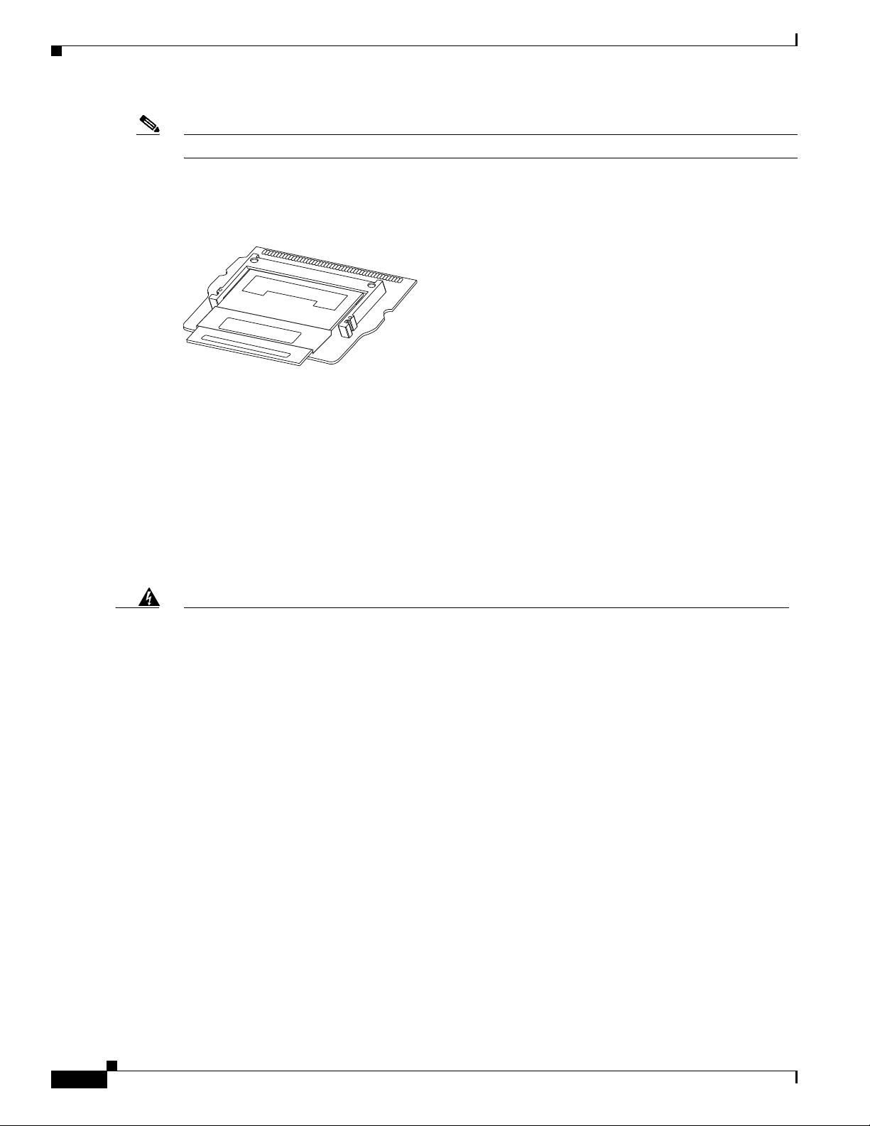
The CompactFlash adapter (see Figure 1) is a device that plugs into the SP bootflash DIMM socket on
the Supervisor Engine 720. This device expands the amount of bootflash memory that is available. The
kits contain a CompactFlash adapter with the CompactFlash installed. The CompactFlash adapter
contains a Cisco IOS image (12.2(18)SXE5 or greater). See your Cisco IOS release notes for the exact
release information.
Corporate Headquarters:
Cisco Systems, Inc., 170 West Tasman Drive, San Jose, CA 95134-1706 USA
© 2005–2006 Cisco Systems, Inc. All rights reserved.
Page 2
Safety Overview
Note The CompactFlash adapter is not supported in systems that run the Catalyst operating system.
This upgrade is applicable only for the SP bootflash; it is independent from the SP DRAM.
Figure 1 CompactFlash Adapter
Safety Overview
Cisco Systems
144401
Safety warnings appear throughout this publication in procedures that may harm you if performed
incorrectly. A warning symbol precedes each warning statement.
Statement 1071—Warning Definition
Warning
Waarschuwing
IMPORTANT SAFETY INSTRUCTIONS
This warning symbol means danger. You are in a situation that could cause bodily injury. Before you
work on any equipment, be aware of the hazards involved with electrical circuitry and be familiar
with standard practices for preventing accidents. Use the statement number provided at the end of
each warning to locate its translation in the translated safety warnings that accompanied this
device.
SAVE THESE INSTRUCTIONS
BELANGRIJKE VEILIGHEIDSINSTRUCTIES
Dit waarschuwingssymbool betekent gevaar. U verkeert in een situatie die lichamelijk letsel kan
veroorzaken. Voordat u aan enige apparatuur gaat werken, dient u zich bewust te zijn van de bij
elektrische schakelingen betrokken risico's en dient u op de hoogte te zijn van de standaard
praktijken om ongelukken te voorkomen. Gebruik het nummer van de verklaring onderaan de
waarschuwing als u een vertaling van de waarschuwing die bij het apparaat wordt geleverd, wilt
raadplegen.
BEWAAR DEZE INSTRUCTIES
Cisco CompactFlash Adapter for Bootflash Upgrade Installation Note
2
78-17277-04
Page 3

Safety Overview
Varoitus
Attention
Warnung
TÄRKEITÄ TURVALLISUUSOHJEITA
Tämä varoitusmerkki merkitsee vaaraa. Tilanne voi aiheuttaa ruumiillisia vammoja. Ennen kuin
käsittelet laitteistoa, huomioi sähköpiirien käsittelemiseen liittyvät riskit ja tutustu
onnettomuuksien yleisiin ehkäisytapoihin. Turvallisuusvaroitusten käännökset löytyvät laitteen
mukana toimitettujen käännettyjen turvallisuusvaroitusten joukosta varoitusten lopussa näkyvien
lausuntonumeroiden avulla.
SÄILYTÄ NÄMÄ OHJEET
IMPORTANTES INFORMATIONS DE SÉCURITÉ
Ce symbole d'avertissement indique un danger. Vous vous trouvez dans une situation pouvant
entraîner des blessures ou des dommages corporels. Avant de travailler sur un équipement, soyez
conscient des dangers liés aux circuits électriques et familiarisez-vous avec les procédures
couramment utilisées pour éviter les accidents. Pour prendre connaissance des traductions des
avertissements figurant dans les consignes de sécurité traduites qui accompagnent cet appareil,
référez-vous au numéro de l'instruction situé à la fin de chaque avertissement.
CONSERVEZ CES INFORMATIONS
WICHTIGE SICHERHEITSHINWEISE
Dieses Warnsymbol bedeutet Gefahr. Sie befinden sich in einer Situation, die zu Verletzungen führen
kann. Machen Sie sich vor der Arbeit mit Geräten mit den Gefahren elektrischer Schaltungen und
den üblichen Verfahren zur Vorbeugung vor Unfällen vertraut. Suchen Sie mit der am Ende jeder
Warnung angegebenen Anweisungsnummer nach der jeweiligen Übersetzung in den übersetzten
Sicherheitshinweisen, die zusammen mit diesem Gerät ausgeliefert wurden.
Avvertenza
Advarsel
BEWAHREN SIE DIESE HINWEISE GUT AUF.
IMPORTANTI ISTRUZIONI SULLA SICUREZZA
Questo simbolo di avvertenza indica un pericolo. La situazione potrebbe causare infortuni alle
persone. Prima di intervenire su qualsiasi apparecchiatura, occorre essere al corrente dei pericoli
relativi ai circuiti elettrici e conoscere le procedure standard per la prevenzione di incidenti.
Utilizzare il numero di istruzione presente alla fine di ciascuna avvertenza per individuare le
traduzioni delle avvertenze riportate in questo documento.
CONSERVARE QUESTE ISTRUZIONI
VIKTIGE SIKKERHETSINSTRUKSJONER
Dette advarselssymbolet betyr fare. Du er i en situasjon som kan føre til skade på person. Før du
begynner å arbeide med noe av utstyret, må du være oppmerksom på farene forbundet med
elektriske kretser, og kjenne til standardprosedyrer for å forhindre ulykker. Bruk nummeret i slutten
av hver advarsel for å finne oversettelsen i de oversatte sikkerhetsadvarslene som fulgte med denne
enheten.
TA VARE PÅ DISSE INSTRUKSJONENE
78-17277-04
Cisco CompactFlash Adapter for Bootflash Upgrade Installation Note
3
Page 4
Safety Overview
Aviso
¡Advertencia!
Varning!
INSTRUÇÕES IMPORTANTES DE SEGURANÇA
Este símbolo de aviso significa perigo. Você está em uma situação que poderá ser causadora de
lesões corporais. Antes de iniciar a utilização de qualquer equipamento, tenha conhecimento dos
perigos envolvidos no manuseio de circuitos elétricos e familiarize-se com as práticas habituais de
prevenção de acidentes. Utilize o número da instrução fornecido ao final de cada aviso para
localizar sua tradução nos avisos de segurança traduzidos que acompanham este dispositivo.
GUARDE ESTAS INSTRUÇÕES
INSTRUCCIONES IMPORTANTES DE SEGURIDAD
Este símbolo de aviso indica peligro. Existe riesgo para su integridad física. Antes de manipular
cualquier equipo, considere los riesgos de la corriente eléctrica y familiarícese con los
procedimientos estándar de prevención de accidentes. Al final de cada advertencia encontrará el
número que le ayudará a encontrar el texto traducido en el apartado de traducciones que acompaña
a este dispositivo.
GUARDE ESTAS INSTRUCCIONES
VIKTIGA SÄKERHETSANVISNINGAR
Denna varningssignal signalerar fara. Du befinner dig i en situation som kan leda till personskada.
Innan du utför arbete på någon utrustning måste du vara medveten om farorna med elkretsar och
känna till vanliga förfaranden för att förebygga olyckor. Använd det nummer som finns i slutet av
varje varning för att hitta dess översättning i de översatta säkerhetsvarningar som medföljer denna
anordning.
SPARA DESSA ANVISNINGAR
Cisco CompactFlash Adapter for Bootflash Upgrade Installation Note
4
78-17277-04
Page 5
Safety Overview
Aviso
Advarsel
INSTRUÇÕES IMPORTANTES DE SEGURANÇA
Este símbolo de aviso significa perigo. Você se encontra em uma situação em que há risco de lesões
corporais. Antes de trabalhar com qualquer equipamento, esteja ciente dos riscos que envolvem os
circuitos elétricos e familiarize-se com as práticas padrão de prevenção de acidentes. Use o
número da declaração fornecido ao final de cada aviso para localizar sua tradução nos avisos de
segurança traduzidos que acompanham o dispositivo.
GUARDE ESTAS INSTRUÇÕES
VIGTIGE SIKKERHEDSANVISNINGER
Dette advarselssymbol betyder fare. Du befinder dig i en situation med risiko for
legemesbeskadigelse. Før du begynder arbejde på udstyr, skal du være opmærksom på de
involverede risici, der er ved elektriske kredsløb, og du skal sætte dig ind i standardprocedurer til
undgåelse af ulykker. Brug erklæringsnummeret efter hver advarsel for at finde oversættelsen i de
oversatte advarsler, der fulgte med denne enhed.
GEM DISSE ANVISNINGER
78-17277-04
Cisco CompactFlash Adapter for Bootflash Upgrade Installation Note
5
Page 6
Safety Overview
Cisco CompactFlash Adapter for Bootflash Upgrade Installation Note
6
78-17277-04
Page 7
Safety Overview
78-17277-04
Cisco CompactFlash Adapter for Bootflash Upgrade Installation Note
7
Page 8

Installing the SP Bootflash Memory Upgrade Kit
Installing the SP Bootflash Memory Upgrade Kit
The SP memory upgrade procedure is divided into the following tasks:
• Verifying the SP ROMMON Version, page 8
• Upgrading and Verifying the SP ROMMON Image, page 8
• Removing the Supervisor Engine 720, page 10
• Installing the CompactFlash Adapter, page 13
• Reinstalling the Supervisor Engine 720, page 16
Verifying the SP ROMMON Version
An SP ROMMON upgrade may be required to support the CompactFlash adapter; you must determine
what SP ROMMON release is installed on the Supervisor Engine 720 prior to performing an SP
ROMMON upgrade. The minimum SP ROMMON release required is 8.4(2). To determine the currently
running SP ROMMON release, enter the remote command switch show version | include ROM
command
If your system is running SP ROMMON Release 8.4(2) or a later release, you can continue on to
“Removing the Supervisor Engine 720” section on page 10. If your SP ROMMON release is earlier than
8.4(2), you must upgrade the SP ROMMON image. Go to the “Upgrading and Verifying the SP
ROMMON Image” section on page 8.
Upgrading and Verifying the SP ROMMON Image
In order to utilize the SP CompactFlash adapter, your Supervisor Engine 720 must have SP ROMMON
Release 8.4(2) or a later release installed on it.
Note The upgrade task description is based on the Supervisor Engine 720 installed in a 9-slot chassis currently
running ROMMON from its S (Gold) region; the ROMMON upgrade to support the CompactFlash
adapter will be done in the F1 region.
Cisco CompactFlash Adapter for Bootflash Upgrade Installation Note
8
78-17277-04
Page 9

Installing the SP Bootflash Memory Upgrade Kit
To upgrade your SP ROMMON, perform these steps:
Step 1 Download the latest SP ROMMON (c6ksup3-rm2.srec.8.4.2) from cisco.com and copy it to any of the
following locations: sup-bootflash:, bootflash:, disk0:, or disk1: by entering this URL:
http://www.ciso.com/cgi-bin/tablebuild.pl/cat6000-rommon
Step 2 Display the SP ROMMON image status by entering the show rom-monitor slot 5 sp command
Note The system responds with a message indicating that SP is: “Currently running ROMMON from
the S (Gold) region.”
Step 3 Verify that the necessary SP ROMMON version is present by entering the dir
{sup-bootflash:|bootflash:|disk 0:|disk 1:} command.
Step 4 Upgrade the SP ROMMON image by entering the upgrade rom-monitor slot 5 sp file
{sup-bootflash:|bootflash:|disk 0:|disk 1:} c6ksup3-rm2.srec.8.4.2 command.
Note Slot 5 indicates the slot number of the supervisor engine to be upgraded; the supervisor engine
can be installed in either slot 5, slot 6, or in both slots.
Reload the switch by entering the reload command. At the prompt, type Y to confirm and press Enter.
Note Do not perform a Reset.
Step 5 Boot the Cisco IOS software from the boot device. At this point the SP ROMMON upgrade process is
complete; the next steps are used to verify that the upgrade has been completed correctly.
Step 6 Enter privileged EXEC mode by entering the enable command
Step 7 Display the SP ROMMON image status by entering the show rom-monitor slot 5 sp
Note The system responds with a message indicating that SP is “Currently running ROMMON from
F1 region.”
Step 8 Verify the SP ROMMON version by entering the remote command switch show version | include
ROM command.
Note You should see “ROM: System Bootstrap, Version 8.4(2).”
78-17277-04
Cisco CompactFlash Adapter for Bootflash Upgrade Installation Note
9
Page 10

Installing the SP Bootflash Memory Upgrade Kit
Removing the Supervisor Engine 720
Warning
Only trained and qualified personnel should be allowed to install, replace, or service this equipment.
Statement 1030
The following tools are required to perform the bootflash upgrade kit installation:
• 3/16-inch flat-blade screwdriver for the captive installation screws on the supervisor engine
• Antistatic mat or foam pad to support and protect the removed supervisor engine
• Your own ESD-prevention equipment or the disposable grounding wrist strap included with all
upgrade kits, field-replaceable units (FRUs), and spares
Warning
Warning
Caution Always use an ESD wrist strap when handling the Supervisor Engine 720 or coming in contact with
Blank faceplates and cover panels serve three important functions: they prevent exposure to
hazardous voltages and currents inside the chassis; they contain electromagnetic interference (EMI)
that might disrupt other equipment; and they direct the flow of cooling air through the chassis. Do not
operate the system unless all cards, faceplates, front covers, and rear covers are in place.
1029
Hazardous voltage or energy is present on the backplane when the system is operating. Use caution
when servicing.
Statement 1034
Statement
internal components.
To remove the supervisor engine, follow these steps:
Step 1 Power down your system.
Step 2 Disconnect any network interface cables attached to the supervisor engine.
Step 3 Attach an ESD grounding strap to your wrist and to ground. (If you are unsure about the correct way to
attach an ESD grounding strap, see the “Attaching Your ESD Grounding Strap” section on page 24 for
instructions.)
Step 4 Verify that the captive installation screws on all of the modules in the chassis are tight. This step ensures
that the space created by the removed module is maintained.
Note If the captive installation screws are loose, the EMI gaskets on the installed modules will push
the modules toward the open slot, reducing the opening size and making it difficult to reinstall
the module.
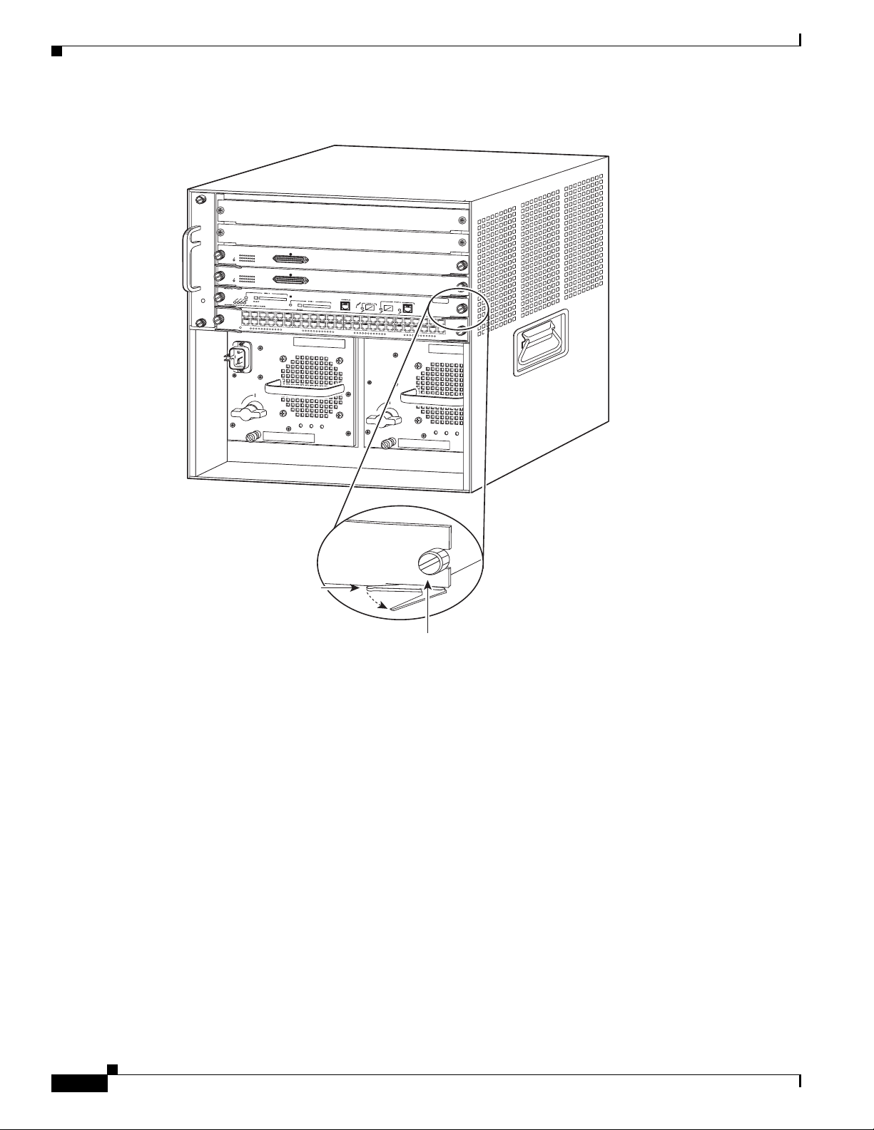
Step 5 Loosen the two captive screws on the supervisor engine that is to be removed.
10
Cisco CompactFlash Adapter for Bootflash Upgrade Installation Note
78-17277-04
Page 11

Installing the SP Bootflash Memory Upgrade Kit
Step 6 Depending on the orientation of the slots in the chassis (horizontal or vertical), perform one of the
following two sets of steps:
Horizontal slots
a. Place your thumbs on the left and right ejector levers, and simultaneously rotate the levers outward
to unseat the supervisor engine from the backplane connector. (See Figure 2.)
b. Grasp the front edge of the supervisor engine, and slide the supervisor engine partially out of the
slot. Place your other hand under the supervisor engine to support the weight of the module. Do not
touch the module circuitry. (See Figure 3.)
Vertical slots
a. Place your thumbs on the ejector levers located at the top and bottom of the supervisor engine, and
simultaneously rotate the levers outward to unseat the supervisor engine from the backplane
connector.
b. Grasp the edges of the supervisor engine, and slide the supervisor engine straight out of the slot. Do
not touch the module circuitry.
Step 7 Immediately place the supervisor engine on an antistatic mat or antistatic foam.
78-17277-04
Cisco CompactFlash Adapter for Bootflash Upgrade Installation Note
11
Page 12
Installing the SP Bootflash Memory Upgrade Kit
Figure 2 Opening the Ejector Levers (Horizontal Chassis Shown)
1
2
W
S-
X6624-FX
S
0
1
3
4
6
7
9
1
2
1
1
1
2
TUS
3
24 POR
T FXS
W
S-X6624-FX
4
24
POR
T FXS A
5
W
S
X
6
3
4
8
R
J
-4
6
4-1
1
2
4
STA
5
7
2
8
0
1
3
1
1
2
2
2
3
5
6
8
9
1
1
4
1
1
2
2
A
NALOG
STA
TIO
N
S
0
1
3
4
6
7
9
1
2
1
1
1
2
1
2
4
STATUS
5
7
24-1
8
0
1
3
1
1
2
2
2
3
5
6
8
9
1
1
4
1
1
2
2
NALO
G STA
TION
1
2
5
V
1
1
2
3
4
5
6
7
1
8
0
/
9
10
11
12
2
4
1
4
8
P
O
R
T
1
0
0
B
A
S
E
T
4
6
2
2
E
T
H
E
R
N
E
T
S
W
IT
C
13
H
14
15
0
16
17
18
M
O
D
19
U
4
L
2
E
21
22
23
2
6
8
3
3
8
4
I
N
G
5
2
0
26
27
28
29
3
31
32
33
34
35
36
7
8
3
3
39
40
41
42
43
44
45
46
47
48
o
Ejector lever
o
INPUT
FAN
OUTPUT
OK
OK
FAI
L
INPUT
FAN
OUTPUT
OK
OK
FAI
L
91525
Captive
installation
screw
12
Cisco CompactFlash Adapter for Bootflash Upgrade Installation Note
78-17277-04
Page 13

Installing the SP Bootflash Memory Upgrade Kit
Figure 3 Removing the Module from the Chassis (Horizontal Chassis Shown)
1
2
W
S-X6624-FX
S
0
1
3
4
6
7
9
1
2
1
1
1
3
4
5
6
2
-1
1
2
4
STATUS
5
7
24
8
0
1
3
1
1
2
2
2
3
5
6
8
9
1
1
4
1
1
2
2
24
POR
T FXS A
NALO
G STA
TI
ON
W
S-X6624-FX
S
0
1
3
4
6
7
9
1
2
1
1
1
2
-1
1
2
4
STATUS
5
7
24
8
0
1
3
1
1
2
2
2
3
5
6
8
9
1
1
4
1
1
2
2
24 P
ORT F
XS AN
A
L
OG STA
TION
W
S
-
X
6
3
4
8
-
R
J
-
4
5
V
1
2
2
4
1
1
4
8
P
O
R
1
T
2
3
4
5
6
7
1
8
0
/
1
0
9
0
2
B
A
S
E
-
T
10
11
1
4
6
2
2
E
T
H
E
R
N
E
T
S
W
I
T
C
13
H
14
15
16
17
18
M
O
D
19
U
L
20
E
21
22
23
24
6
8
3
3
8
4
I
N
G
5
9
2
26
1
27
2
28
2
4
30
3
3
33
3
35
36
9
0
37
2
38
3
3
4
4
41
4
4
4
45
46
47
48
o
Installing the CompactFlash Adapter
To install the CompactFlash adapter, follow these steps:
Step 1 Locate the SP BOOTFLASH DIMM socket on the Supervisor Engine 720. (See Figure 4.) The SP
BOOTFLASH DIMM is on the left side of the Supervisor Engine 720 as you face the front of the board;
the RP BOOTFLASH DIMM is on the right side of the Supervisor Engine 720 as you face the front of
the board.
Note The DIMM is a sensitive component that is susceptible to ESD damage. To prevent ESD damage,
wear an ESD grounding wrist strap and handle the DIMM by the edges only; avoid touching the
memory modules, pins, or traces (including the metal fingers along the connector edge of the
DIMM). Attach an ESD grounding strap to your wrist and to ground. (If you are unsure about
the correct way to attach an ESD grounding strap, see the “Attaching Your ESD Grounding
Strap” section on page 24 for instructions.)
o
INPUT
FAN
OUTPUT
OK
OK
FAI
L
INPUT
FAN
OUTPUT
OK
OK
FAI
L
91526
78-17277-04
Cisco CompactFlash Adapter for Bootflash Upgrade Installation Note
13
Page 14

Installing the SP Bootflash Memory Upgrade Kit
Figure 4 SP and RP DIMM Locations on the Supervisor Engine 720
SP Bootflash
RP Bootflash
Step 2
Release the SP DIMM from the socket by simultaneously releasing the two locking spring clip tabs on
either side of the DIMM socket. (See Figure 5, left view.) The DIMM will flip up in the socket. (See
Figure 5, right view.)
Step 3 Hold the DIMM by its edges and carefully remove it from the DIMM socket.
Figure 5 Removing the DIMM
144402
144403
14
Step 4
Cisco CompactFlash Adapter for Bootflash Upgrade Installation Note
Immediately place the DIMM in an antistatic bag.
78-17277-04
Page 15

Installing the SP Bootflash Memory Upgrade Kit
Step 5 Open the antistatic bag containing the SP CompactFlash adapter.
Note The SP CompactFlash adapter has a label attached to the CompactFlash identifying it as the SP
CompactFlash adapter.
Step 6 Carefully align the CompactFlash adapter edge connector with the DIMM socket. Slide the
CompactFlash adapter edge connector at an angle into the socket. (See Figure 6.)
Note Make sure that the CompactFlash adapter edge connector is fully inserted into the DIMM socket.
Step 7 Press down firmly on both edges of the CompactFlash adapter until the CompactFlash adapter latches
into place. Visually verify that both locking spring clips are fully engaged over the edges of the
CompactFlash adapter. (See Figure 6.)
Figure 6 Installing the CompactFlash Adapter
DIMM Socket
SP CompactFlash Adapter
78-17277-04
144404
You are now ready to reinstall the Supervisor Engine 720 into the switch chassis.
Cisco CompactFlash Adapter for Bootflash Upgrade Installation Note
15
Page 16

Installing the SP Bootflash Memory Upgrade Kit
Reinstalling the Supervisor Engine 720
Caution During this procedure, wear grounding wrist straps and handle modules by the carrier edges only to
avoid ESD damage to the card.
To reinstall the Supervisor Engine 720 in the chassis, follow these steps:
Step 1 Attach an ESD grounding strap to your wrist and to ground. (If you are unsure about the correct way to
attach an ESD grounding strap, see the “Attaching Your ESD Grounding Strap” section on page 24 for
instructions.)
Step 2 Verify that the captive installation screws are tightened on all modules installed in the chassis. This
action assures that the EMI gaskets on all modules are fully compressed in order to maximize the
opening space for the removed module.
Note If the captive installation screws are loose, the EMI gaskets on the installed modules will push
adjacent modules toward the open slot, reducing the opening size and making it difficult to
install the removed module.
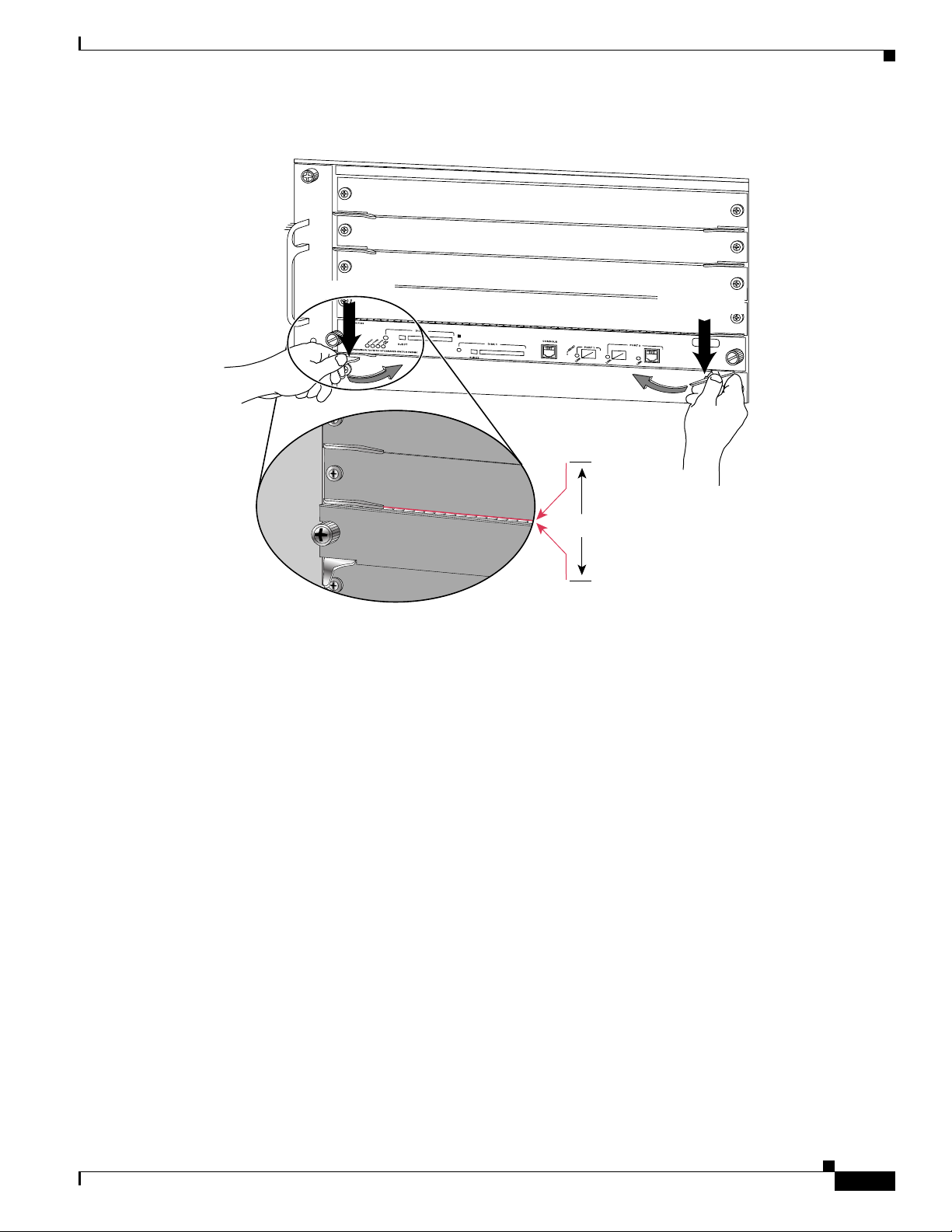
Step 3 Fully open both ejector levers on the supervisor engine that is being installed. (See Figure 7.)
16
Cisco CompactFlash Adapter for Bootflash Upgrade Installation Note
78-17277-04
Page 17

Installing the SP Bootflash Memory Upgrade Kit
4
3
5
5
4
6
6
WS-SUP72
SUPERVISOR 720 WITH INTEGRATED SWITCH FABRIC
Figure 7 Positioning the Module in a Horizontal Slot Chassis
Insert module
between slot guides
FAN
STATUS
EMI gasket
1
2
3
4
5
6
EMI gasket
o
INPUT
FAN
OUTPUT
OK
OK
FAIL
o
INPUT
FAN
OUTPUT
OK
OK
FAIL
91527
Ejector lever fully
extended
78-17277-04
Cisco CompactFlash Adapter for Bootflash Upgrade Installation Note
17
Page 18

Installing the SP Bootflash Memory Upgrade Kit
Step 4 Depending on the orientation of the slots in the chassis (horizontal or vertical), perform one of the
following two sets of steps:
Horizontal slots
a. Position the supervisor engine in the slot. (See Figure 7.) Make sure that you align the sides of the
module carrier with the slot guides on each side of the slot.
b. Carefully slide the supervisor engine into the slot until the EMI gasket along the top edge of the
module makes contact with the module in the slot above it and both ejector levers have closed to
approximately 45 degrees with respect to the module faceplate. (See Figure 8.)
c. Using the thumb and forefinger of each hand, grasp the two ejector levers and press down to create
a small 0.040 inch (1 mm) gap between the supervisor engine’s EMI gasket and the module above
it. (See Figure 8.)
Note Do not press down too forcefully on the levers because they will bend and be damaged.
d. While pressing down, simultaneously close the left and right ejector levers to fully seat the
supervisor engine in the backplane connector. The ejector levers are fully closed when they are flush
with the module faceplate. (See Figure 8.)
Note Failure to fully seat the module in the backplane connector can result in error messages.
e. Tighten the two captive installation screws on the supervisor engine.
Note Make sure that the ejector levers are fully closed before tightening the captive installation
screws.
f. Power up your system.
Note Depending on how your system bootstring is configured, your system might stay in
ROMMON. To boot the system from the CF adapter, enter the boot bootdisk: command.
Once you install the CF adapter, you must define the Cisco IOS bootstring as
boot system flash sup-bootdisk:[image name]
With SP ROMMON Release 8.4(2), the bootstring has to be defined as sup-bootdisk:. SP
ROMMON releases later than 8.4(2) only accept the bootstring defined as sup-bootflash:.
g. Verify that the Supervisor Engine 720 STATUS LED is lit.
Periodically check the STATUS LED. If the STATUS LED changes from orange to green, the
module has successfully completed the boot process and is now online.
If the STATUS LED remains orange or turns red, the supervisor engine has not successfully
completed the boot process and may have encountered an error.
18
Cisco CompactFlash Adapter for Bootflash Upgrade Installation Note
78-17277-04
Page 19
Installing the SP Bootflash Memory Upgrade Kit
4
3
5
5
4
6
6
Figure 8 Clearing the EMI Gasket in a Horizontal Slot Chassis
1
2
3
Press down
4
1
FAN
STATUS
5
6
2
Press down
1mm
Gap between the module
EMI gasket and the
module above it
91528
78-17277-04
Cisco CompactFlash Adapter for Bootflash Upgrade Installation Note
19
Page 20
Installing the SP Bootflash Memory Upgrade Kit
4
3
6
Vertical slots
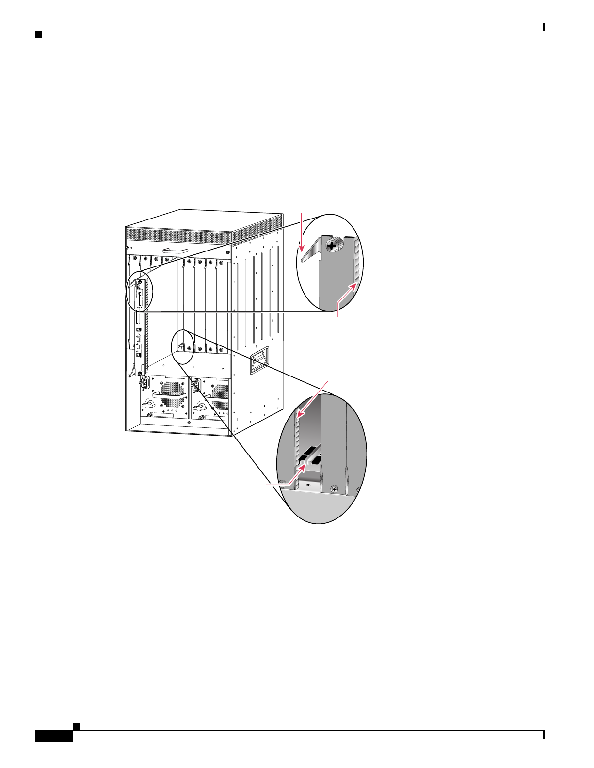
a. Position the supervisor engine in the slot. (See Figure 9.) Make sure that you align the sides of the
module carrier with the slot guides on the top and bottom of the slot.
b. Carefully slide the supervisor engine into the slot until the EMI gasket along the right edge of the
module makes contact with the module in the slot adjacent to it and both ejector levers have closed
to approximately 45 degrees with respect to the module faceplate. (See Figure 10.)
Figure 9 Positioning the Module in a Vertical Slot Chassis
FAN
STATUS
4
8
24 PO
WS-X6224
R
T 100FX
S
T
A
T
U
S
A
C
T
IV
E
Ejector lever fully
extended
SUPERVISOR 720 WITH INTEGRATED SWITCH FABRIC.
W
S
-S
U
P
7
2
EMI
gasket
N
S
E
E
X
L
T
E
C
T
4
8
EMI
gasket
o
INPUT
o
FAN
OUTPUT
OK
OK
FAIL
INPUT
FAN
OUTPUT
OK
OK
FAIL
Insert module
between slot guides
91529
20
Cisco CompactFlash Adapter for Bootflash Upgrade Installation Note
78-17277-04
Page 21

Installing the SP Bootflash Memory Upgrade Kit
Figure 10 Clearing the EMI Gasket in a Vertical Slot Chassis
Gap between the module
EMI gasket and the
module above it
SUPERVISOR 720 WITH INTEGRATED SWITCH FABRIC.
FAN
STATUS
4
8
Press left
1mm
W
S
-S
U
P
7
2
Press left
o
c.
Using the thumb and forefinger of each hand, grasp the two ejector levers and exert a slight pressure
4
8
INPUT
o
FAN
OUTPUT
OK
OK
FAIL
INPUT
FAN
OUTPUT
OK
OK
FAIL
91530
to the left, deflecting it approximately 0.040 inches (1 mm) creating a small gap between the
supervisor engine’s EMI gasket and the module adjacent to it. (See Figure 10.)
Note Do not exert too much pressure on the ejector levers because they will bend and be damaged.
d. While pressing down on the ejector levers, simultaneously close the levers to fully seat the
supervisor engine in the backplane connector. The ejector levers are fully closed when they are flush
with the module faceplate.
78-17277-04
Cisco CompactFlash Adapter for Bootflash Upgrade Installation Note
21
Page 22

Removing and Installing the CompactFlash in the CompactFlash Adapter
e. Tighten the two captive installation screws on the supervisor engine.
Note Make sure that the ejector levers are fully closed before tightening the captive installation
screws.
f. Power up your system.
Note Depending on how your system bootstring is configured, your system might stay in
ROMMON. To boot the system from the CF adapter, enter the boot bootdisk: command.
Once you install the CF adapter, you must define the Cisco IOS bootstring as
boot system flash sup-bootdisk:[image name]
With SP ROMMON Release 8.4(2), the bootstring has to be defined as sup-bootdisk:. SP
ROMMON releases later than 8.4(2) only accept the bootstring defined as sup-bootflash:.
g. Verify that the Supervisor Engine 720 STATUS LED is lit. Periodically check the STATUS LED.
If the STATUS LED changes from orange to green, the module has successfully completed the boot
process and is now online.
If the STATUS LED remains orange or turns red, the supervisor engine has not successfully
completed the boot process and may have encountered an error.
Removing and Installing the CompactFlash in the CompactFlash
Adapter
CompactFlash is normally shipped already installed in the CompactFlash adapter. However, there might
be occasions when you will need to replace a defective CompactFlash or swap an existing CompactFlash
for a larger capacity device.
To remove the CompactFlash from the adapter, follow these steps:
Step 1 Remove the Supervisor Engine 720 from the system chassis. See the “Removing the Supervisor
Engine 720” section on page 10.
Step 2 Place the Supervisor Engine 720 on an antistatic mat.
Caution Do not remove the CompactFlash from the CompactFlash adapter while the adapter is installed in the
DIMM socket; you must remove the CompactFlash adapter first.
Step 3 Release the CompactFlash adapter from the DIMM socket by simultaneously releasing the two locking
spring clips on either side of the DIMM socket. The CompactFlash adapter will flip up in the socket.
Step 4 Hold the CompactFlash adapter by its edges and carefully remove it from the DIMM socket.
Step 5 Holding the CompactFlash adapter in one hand as shown in Figure 11, grasp the CompactFlash with your
other hand (View 1) and carefully and firmly pull the CompactFlash (Views 2 and 3) to disconnect the
CompactFlash from the adapter.
22
Cisco CompactFlash Adapter for Bootflash Upgrade Installation Note
78-17277-04
Page 23
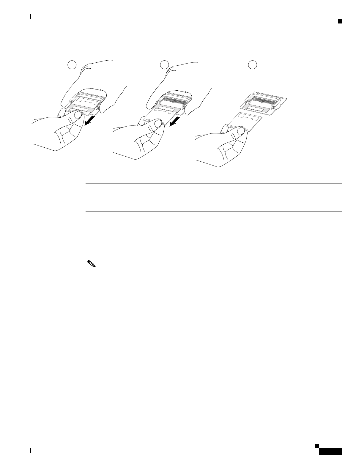
Figure 11 Removing the CompactFlash from the Adapter
1 2 3
Cisco Systems
Cisco Systems
Removing and Installing the CompactFlash in the CompactFlash Adapter
Cisco Systems
144747
To install the CompactFlash in the adapter, follow these steps:
Step 1 Remove the replacement CompactFlash from its packaging.
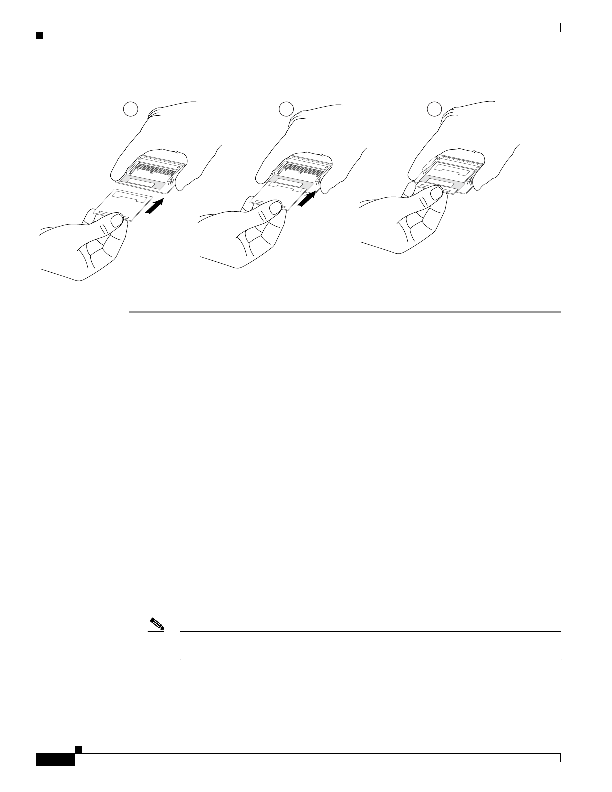
Step 2 Grasp the empty adapter and the CompactFlash, and position the CompactFlash in front of the adapter
as shown in Figure 12, View 1. Align the slots in the CompactFlash with the rails in the adapter.
Step 3 Slide the CompactFlash into the adapter until the CompactFlash is firmly seated in the adapter connector.
(See Figure 12, Views 2 and 3.)
Note To make good electrical contact, you must fully insert the adapter’s connector pins into the
CompactFlash; the pins should not be visible.
Step 4 Install the CompactFlash adapter in the DIMM socket using Step 6 and Step 7 on Page 15.
Step 5 Reinstall the Supervisor Engine 720 in the chassis following the “Reinstalling the Supervisor Engine
720” procedure on page 16.
78-17277-04
Cisco CompactFlash Adapter for Bootflash Upgrade Installation Note
23
Page 24
Attaching Your ESD Grounding Strap
Figure 12 Installing a CompactFlash in the Adapter
1 2 3
Cisco Systems
Cisco Systems
Cisco Systems
144749
Attaching Your ESD Grounding Strap
Electrostatic discharge (ESD) damage, which can occur when modules or other FRUs are improperly
handled, results in intermittent or complete failures. Modules consist of printed circuit boards that are
fixed in metal carriers. Electromagnetic interference (EMI) shielding and connectors are integral
components of the carrier. Although the metal carrier helps to protect the board from ESD, always use
an ESD grounding strap when handling modules.
Follow these guidelines for preventing ESD damage:
• Always use an ESD wrist strap and ensure that it makes maximum contact with bare skin. ESD
grounding straps are available with banana plugs, metal spring clips, or alligator clips. All
Catalyst 6500 series chassis are equipped with a banana plug connector (identified by the ground
symbol next to the connector) on the front panel. If you have an older Catalyst 6500 series chassis
equipped with a plastic banana plug connector, we recommend that you use either the supplied ESD
grounding wrist strap (with a metal clip) or an ESD grounding wrist strap equipped with an alligator
clip. If you have a newer Catalyst 6500 series chassis that has a bare metal hole as the banana plug
connector (also identified by the ground symbol next to the connector), we recommend that you use
a personal ESD grounding strap equipped with a banana plug.
• If you choose to use the disposable ESD wrist strap supplied with most FRUs or an ESD wrist strap
equipped with an alligator clip, you must attach the system ground lug to the chassis in order to
provide a proper grounding point for the ESD wrist strap.
Note This system ground is also referred to as the network equipment building system (NEBS)
ground.
24
• If your chassis does not have the system ground attached, you must install the system ground lug.
Refer to the online Catalyst 6500 Series Switches Installation Guide for the procedure.
Cisco CompactFlash Adapter for Bootflash Upgrade Installation Note
78-17277-04
Page 25

Attaching Your ESD Grounding Strap
Note You do not need to attach a supplemental system ground wire to the system ground lug; the
lug provides a direct path to the bare metal of the chassis.
After you install the system ground lug, you can perform the procedure in this section.
To attach the ESD wrist strap, follow these steps:
Step 1 Attach the ESD wrist strap to bare skin as follows:
a. If you are using the ESD wrist strap supplied with the FRUs, open the wrist strap package and
unwrap the ESD wrist strap. Place the black conductive loop over your wrist and tighten the strap
so that it makes good contact with your bare skin.
b. If you are using an ESD wrist strap equipped with an alligator clip, open the package and remove
the ESD wrist strap. Locate the end of the wrist strap that attaches to your body and secure it to your
bare skin.
Step 2 Grasp the spring or alligator clip on the ESD wrist strap and momentarily touch the clip to a bare metal
spot (unpainted surface) on the rack. We recommend that you touch the clip to an unpainted rack rail so
that any built-up static charge is then safely dissipated to the entire rack.
Step 3 Attach either the spring clip or the alligator clip to the ground lug screw as follows (see Figure 13):
a. If you are using the ESD wrist strap that is supplied with the FRUs, squeeze the spring clip jaws
open, position the spring clip to one side of the system ground lug screw head, and slide the spring
clip over the lug screw head so that the spring clip jaws close behind the lug screw head.
Note The spring clip jaws do not open wide enough to fit directly over the head of the lug screw
or the lug barrel.
b. If you are using an ESD wrist strap that is equipped with an alligator clip, attach the alligator clip
directly over the head of the system ground lug screw or to the system ground lug barrel.
78-17277-04
Cisco CompactFlash Adapter for Bootflash Upgrade Installation Note
25
Page 26

Module Handling Guidelines
Figure 13 Attaching the ESD Wrist Strap Clip to the System Ground Lug Screw
Clip
ESD ground
strap
W
S
-X
6
K
-S
U
P
2-2
T
S
S
U
P
E
R
V
IS
O
R
O
S
M
-4
O
4
P
O
R
T
O
O
S
M
-4
O
4
P
O
R
T
O
Grounding lug
Screw
JE
C
T
E
V
I
T
X
C
R
A
X
T
X
R
R
E
I
M
R
R
R
A
A
L
C
A
E
V
I
T
X
C
R
A
X
T
X
R
R
E
I
M
R
R
R
A
A
L
C
A
Side view of
grounding lug
S
w
itch L
oad
10
0%
1%
E
V
X
I
T
T
X
C
R
A
X
T
X
R
2
T
R
E
R
O
P
2
T
R
O
P
3
I
M
R
T
R
R
R
A
A
O
L
C
P
A
E
V
X
I
T
T
X
C
R
A
X
T
X
R
R
E
3
I
M
R
T
R
R
R
A
A
O
L
C
P
A
P
O
RT
1
K
IN
L
E
V
X
I
T
T
X
C
R
A
X
T
X
R
R
IE
M
R
R
R
A
A
O
L
C
P
A
E
X
IV
T
T
X
C
R
A
X
T
X
R
R
E
I
M
R
R
R
A
A
O
L
C
P
A
System ground
connector
P
O
R
T 2
K
N
I
L
X
T
4
T
R
X
T
4
T
R
144607
Slide clip
behind screw
Clip installed
behind screw
G
E
T
E
M
S
L
M
G
U
O
E
T
M
T
T
S
A
E
S
N
R
S
Y
O
W
E
S
C
P
R
C
O
N
S
O
LE
P
O
R
T
M
O
D
E
C
ON
SO
LE
2
C
1
2
P
O
S
S
I
1
S
U
T
A
T
S
C
-1
2
P
O
C
1
2
P
O
S
-S
S
U
T
A
T
S
C
1
2
P
O
3
2
4
S
S
M
IR
K
K
N
I
K
N
L
I
1
N
2
L
I
L
I
1
2
S
S
M
IR
3
3
4
K
K
N
I
K
N
L
I
1
2
L
IN
L
3
P
C
M
CIA E
E
V
I
T
X
C
X
R
A
T
X
T
X
T
R
E
S
E
R
R
E
1
I
M
R
T
R
R
R
A
A
O
L
C
P
A
K
N
I
4
L
E
V
I
T
X
C
X
R
A
T
X
T
X
T
R
E
S
E
R
R
E
1
I
M
R
T
R
R
R
A
A
O
L
C
P
A
K
N
I
4
L
Module Handling Guidelines
Follow these guidelines when handling modules:
• Handle carriers by available handles or edges only; avoid touching the printed circuit boards or
connectors.
• Place a removed component board-side-up on an antistatic surface or in a static shielding container.
If you plan to return the component to the factory, immediately place it in a static shielding
container.
• Never attempt to remove the printed circuit board from the metal carrier.
Caution For safety, periodically check the resistance value of the antistatic strap. The measurement should be
between 1 and 10 megohm (Mohm).
Cisco CompactFlash Adapter for Bootflash Upgrade Installation Note
26
78-17277-04
Page 27

Safety Warning Translations
This section repeats in multiple languages the basic warnings that appear in this publication.
Statement 1030—Equipment Installation
Safety Warning Translations
Warning
Waarschuwing
Varoitus
Attention
Warnung
Avvertenza
Advarsel
Aviso
Only trained and qualified personnel should be allowed to install, replace, or service
this equipment.
Deze apparatuur mag alleen worden geïnstalleerd, vervangen of hersteld door bevoegd
geschoold personeel.
Tämän laitteen saa asentaa, vaihtaa tai huoltaa ainoastaan koulutettu ja laitteen
tunteva henkilökunta.
Il est vivement recommandé de confier l'installation, le remplacement et la maintenance de ces
équipements à des personnels qualifiés et expérimentés.
Das Installieren, Ersetzen oder Bedienen dieser Ausrüstung sollte nur geschultem, qualifiziertem
Personal gestattet werden.
Questo apparato può essere installato, sostituito o mantenuto unicamente da un personale
competente.
Bare opplært og kvalifisert personell skal foreta installasjoner, utskiftninger eller service på
dette utstyret.
Apenas pessoal treinado e qualificado deve ser autorizado a instalar, substituir ou fazer a revisão
deste equipamento.
¡Advertencia!
78-17277-04
Varning!
Solamente el personal calificado debe instalar, reemplazar o utilizar este equipo.
Endast utbildad och kvalificerad personal bör få tillåtelse att installera, byta ut eller reparera
denna utrustning.
Cisco CompactFlash Adapter for Bootflash Upgrade Installation Note
27
Page 28

Safety Warning Translations
Aviso
Advarsel
Somente uma equipe treinada e qualificada tem permissão para instalar, substituir ou dar
manutenção a este equipamento.
Kun uddannede personer må installere, udskifte komponenter i eller servicere dette udstyr.
28
Cisco CompactFlash Adapter for Bootflash Upgrade Installation Note
78-17277-04
Page 29

Statement 1029—Blank Faceplates and Cover Panels
Safety Warning Translations
Warning
Waarschuwing
Varoitus
Attention
Blank faceplates and cover panels serve three important functions: they prevent exposure to
hazardous voltages and currents inside the chassis; they contain electromagnetic interference
(EMI) that might disrupt other equipment; and they direct the flow of cooling air through the chassis.
Do not operate the system unless all cards, faceplates, front covers, and rear covers are in place.
Statement
Lege vlakplaten en afdekpanelen vervullen drie belangrijke functies: ze voorkomen blootstelling
aan gevaarlijke voltages en stroom binnenin het frame, ze bevatten elektromagnetische storing
(EMI) hetgeen andere apparaten kan verstoren en ze leiden de stroom van koellucht door het frame.
Het systeem niet bedienen tenzij alle kaarten, vlakplaten en afdekkingen aan de voor- en achterkant
zich op hun plaats bevinden.
Tyhjillä tasolaikoilla ja suojapaneeleilla on kolme tärkeää käyttötarkoitusta: Ne suojaavat
asennuspohjan sisäisille vaarallisille jännitteille ja sähkövirralle altistumiselta; ne pitävät
sisällään elektromagneettisen häiriön (EMI), joka voi häiritä muita laitteita; ja ne suuntaavat
tuuletusilman asennuspohjan läpi. Järjestelmää ei saa käyttää, elleivät kaikki tasolaikat, etukannet
ja takakannet ole kunnolla paikoillaan.
Ne jamais faire fonctionner le système sans que l’intégralité des cartes, des plaques métalliques et
des panneaux avant et arrière ne soient fixés à leur emplacement. Ceux-ci remplissent trois
fonctions essentielles : ils évitent tout risque de contact avec des tensions et des courants
dangereux à l’intérieur du châssis, ils évitent toute diffusion d’interférences électromagnétiques
qui pourraient perturber le fonctionnement des autres équipements, et ils canalisent le flux d’air de
refroidissement dans le châssis.
Warnung
Avvertenza
Advarsel
Aviso
Blanke Faceplates und Abdeckungen haben drei wichtigen Funktionen: (1) Sie schützen vor
gefährlichen Spannungen und Strom innerhalb des Chassis; (2) sie halten elektromagnetische
Interferenzen (EMI) zurück, die andere Geräte stören könnten; (3) sie lenken den kühlenden
Luftstrom durch das Chassis. Das System darf nur betrieben werden, wenn alle Karten, Faceplates,
Voder- und Rückabdeckungen an Ort und Stelle sind.
Le piattaforme bianche e i panelli di protezione hanno tre funzioni importanti: Evitano l'esposizione
a voltaggi e correnti elettriche pericolose nello chassis, trattengono le interferenze
elettromagnetiche (EMI) che potrebbero scombussolare altri apparati e dirigono il flusso di aria per
il raffreddamento attraverso lo chassis. Non mettete in funzione il sistema se le schede, le
piattaforme, i panelli frontali e posteriori non sono in posizione.
Blanke ytterplater og deksler sørger for tre viktige funksjoner: de forhindrer utsettelse for farlig
spenning og strøm inni kabinettet; de inneholder elektromagnetisk forstyrrelse (EMI) som kan
avbryte annet utstyr, og de dirigerer luftavkjølingsstrømmen gjennom kabinettet. Betjen ikke
systemet med mindre alle kort, ytterplater, frontdeksler og bakdeksler sitter på plass.
As faces furadas e os painéis de protecção desempenham três importantes funções: previnem
contra uma exposição perigosa a voltagens e correntes existentes no interior do chassis; previnem
contra interferência electromagnética (EMI) que poderá danificar outro equipamento; e canalizam
o fluxo do ar de refrigeração através do chassis. Não deverá operar o sistema sem que todas as
placas, faces, protecções anteriores e posteriores estejam nos seus lugares.
78-17277-04
Cisco CompactFlash Adapter for Bootflash Upgrade Installation Note
29
Page 30

Safety Warning Translations
¡Advertencia!
Varning!
Las placas frontales y los paneles de relleno cumplen tres funciones importantes: evitan la
exposición a niveles peligrosos de voltaje y corriente dentro del chasis; reducen la interferencia
electromagnética (EMI) que podría perturbar la operación de otros equipos y dirigen el flujo de aire
de enfriamiento a través del chasis. No haga funcionar el sistema a menos que todas las tarjetas,
placas frontales, cubiertas frontales y cubiertas traseras estén en su lugar.
Tomma framplattor och skyddspaneler har tre viktiga funktioner: de förhindrar att personer utsätts
för farlig spänning och ström som finns inuti chassit; de innehåller elektromagnetisk interferens
(EMI) som kan störa annan utrustning; och de styr riktningen på kylluftsflödet genom chassit. Använd
inte systemet om inte alla kort, framplattor, fram- och bakskydd är på plats.
30
Aviso
Plaquetas vazias e painéis de proteção têm três funções importantes: impedem a exposição a
tensões e correntes elétricas perigosas dentro do chassi; apresentam interferência
eletromagnética (EMI) que pode danificar outros equipamentos: direcionam o fluxo do ar
refrigerado pelo chassi. Não opere o sistema a menos que todas as placas, plaquetas, tampas
frontais e tampas traseiras estejam em seu devido lugar.
Advarsel
Blanke frontplader og sidepaneler tjener tre vigtige formål: de forhinder udsættelse for farlig
spænding og strøm inde i chassiset, de isolerer elektromagnetisk interferens (EMI), der kan forstyre
andet udstyr, og de leder en strøm af kølig luft gennem chassiset. Betjen ikke systemet medmindre
alle kort, frontplader, sidepaneler og bagpaneler er på plads.
Cisco CompactFlash Adapter for Bootflash Upgrade Installation Note
78-17277-04
Page 31

Safety Warning Translations
78-17277-04
Cisco CompactFlash Adapter for Bootflash Upgrade Installation Note
31
Page 32

Safety Warning Translations
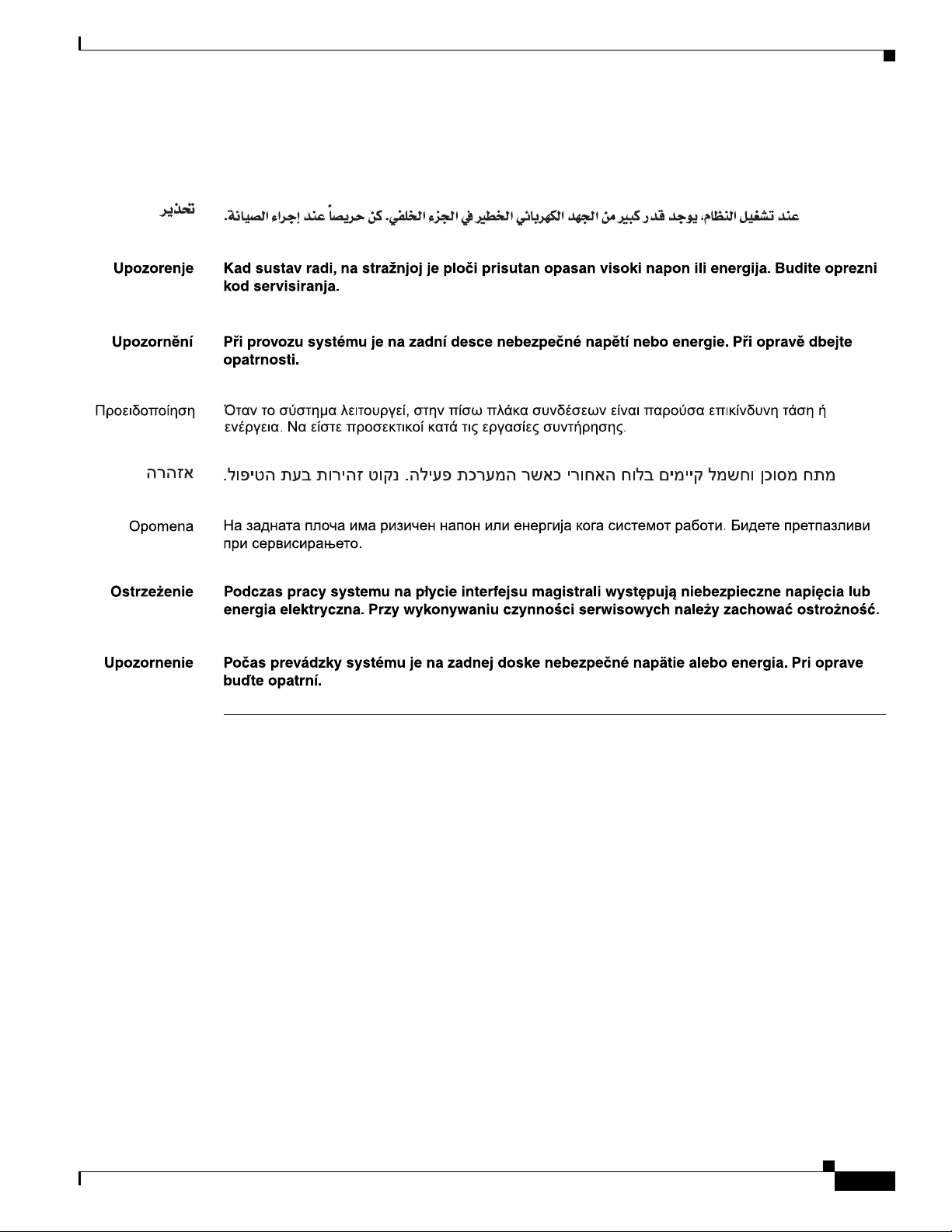
Statement 1034—Backplane Voltage
Warning
Waarschuwing
Varoitus
Attention
Warnung
Avvertenza
Advarsel
Aviso
¡Advertencia!
Hazardous voltage or energy is present on the backplane when the system is operating. Use caution
when servicing.
Er is gevaarlijke spanning of energie aanwezig op de achterplaat wanneer het systeem bediend
wordt. Wees voorzichtig bij het onderhoud.
Kun laite on toiminnassa, taustalevyyn muodostuu vaarallista jännitettä. Ole varovainen
huoltaessasi laitetta.
Lorsque le système est en fonctionnement, des tensions électriques circulent sur le fond de panier.
Prendre des précautions lors de la maintenance.
Wenn das System in Betrieb ist, treten auf der Rückwandplatine gefährliche Spannungen oder
Energien auf. Vorsicht bei der Wartung.
Quando il sistema è in funzione, il pannello posteriore è sotto tensione pericolosa. Prestare
attenzione quando si lavora sul sistema.
Farlig spenning er til stede på bakpanelet når systemet kjøres. Utvis forsiktighet under service.
Há presença de voltagem perigosa ou de energia na placa traseira quando o sistema está em
operação. Tenha cuidado ao fazer a manutenção.
Cuando el sistema está en funcionamiento, el voltaje del plano trasero es peligroso. Tenga cuidado
cuando lo revise.
32
Varning!
Farlig spänning föreligger på bakplattan när systemet körs. Var försiktig vid service.
Aviso
O sistema em funcionamento emite tensão ou energia elétrica perigosa no painel traseiro. Seja
cauteloso ao fazer a manutenção.
Cisco CompactFlash Adapter for Bootflash Upgrade Installation Note
78-17277-04
Page 33
Obtaining Documentation
Advarsel
Der er farlig spænding og energi på bagpladen når systemet er i brug. Vær forsigtig under
servicering.
Obtaining Documentation
Cisco documentation and additional literature are available on Cisco.com. This section explains the
product documentation resources that Cisco offers.
Cisco.com
You can access the most current Cisco documentation at this URL:
http://www.cisco.com/techsupport
You can access the Cisco website at this URL:
http://www.cisco.com
You can access international Cisco websites at this URL:
http://www.cisco.com/public/countries_languages.shtml
78-17277-04
Cisco CompactFlash Adapter for Bootflash Upgrade Installation Note
33
Page 34

Documentation Feedback
Product Documentation DVD
The Product Documentation DVD is a library of technical product documentation on a portable medium.
The DVD enables you to access installation, configuration, and command guides for Cisco hardware and
software products. With the DVD, you have access to the HTML documentation and some of the
PDF files found on the Cisco website at this URL:
http://www.cisco.com/univercd/home/home.htm
The Product Documentation DVD is created monthly and is released in the middle of the month. DVDs
are available singly or by subscription. Registered Cisco.com users can order a Product Documentation
DVD (product number DOC-DOCDVD= or DOC-DOCDVD=SUB) from Cisco Marketplace at the
Product Documentation Store at this URL:
http://www.cisco.com/go/marketplace/docstore
Ordering Documentation
You must be a registered Cisco.com user to access Cisco Marketplace. Registered users may order
Cisco documentation at the Product Documentation Store at this URL:
http://www.cisco.com/go/marketplace/docstore
If you do not have a user ID or password, you can register at this URL:
http://tools.cisco.com/RPF/register/register.do
Documentation Feedback
You can provide feedback about Cisco technical documentation on the Cisco Technical Support &
Documentation site area by entering your comments in the feedback form available in every online
document.
Cisco Product Security Overview
Cisco provides a free online Security Vulnerability Policy portal at this URL:
http://www.cisco.com/en/US/products/products_security_vulnerability_policy.html
From this site, you will find information about how to do the following:
• Report security vulnerabilities in Cisco products
• Obtain assistance with security incidents that involve Cisco products
• Register to receive security information from Cisco
A current list of security advisories, security notices, and security responses for Cisco products is
available at this URL:
34
http://www.cisco.com/go/psirt
To see security advisories, security notices, and security responses as they are updated in real time, you
can subscribe to the Product Security Incident Response Team Really Simple Syndication (PSIRT RSS)
feed. Information about how to subscribe to the PSIRT RSS feed is found at this URL:
http://www.cisco.com/en/US/products/products_psirt_rss_feed.html
Cisco CompactFlash Adapter for Bootflash Upgrade Installation Note
78-17277-04
Page 35

Reporting Security Problems in Cisco Products
Cisco is committed to delivering secure products. We test our products internally before we release them,
and we strive to correct all vulnerabilities quickly. If you think that you have identified a vulnerability
in a Cisco product, contact PSIRT:
• For emergencies only—security-alert@cisco.com
An emergency is either a condition in which a system is under active attack or a condition for which
a severe and urgent security vulnerability should be reported. All other conditions are considered
nonemergencies.
• For nonemergencies —psirt@cisco.com
In an emergency, you can also reach PSIRT by telephone:
• 1 877 228-7302
• 1 408 525-6532
Tip We encourage you to use Pretty Good Privacy (PGP) or a compatible product (for example, GnuPG) to
encrypt any sensitive information that you send to Cisco. P S I RT can wor k with information that has been
encrypted with PGP versions 2.x through 9.x.
Product Alerts and Field Notices
Never use a revoked encryption key or an expired encryption key. The correct public key to use in your
correspondence with PSIRT is the one linked in the Contact Summary section of the Security
Vulnerability Policy page at this URL:
http://www.cisco.com/en/US/products/products_security_vulnerability_policy.html
The link on this page has the current PGP key ID in use.
If you do not have or use PGP, contact PSIRT to find other means of encrypting the data before sending
any sensitive material.
Product Alerts and Field Notices
Modifications to or updates about Cisco products are announced in Cisco Product Alerts and Cisco Field
Notices. You can receive Cisco Product Alerts and Cisco Field Notices by using the Product Alert Tool
on Cisco.com. This tool enables you to create a profile and choose those products for which you want to
receive information.
To access the Product Alert Tool, you must be a registered Cisco.com user. (To register as a Cisco.com
user, go to this URL: http://tools.cisco.com/RPF/register/register.do) Registered users can access the
tool at this URL: http://tools.cisco.com/Support/PAT/do/ViewMyProfiles.do?local=en
78-17277-04
Cisco CompactFlash Adapter for Bootflash Upgrade Installation Note
35
Page 36

Obtaining Technical Assistance
Obtaining Technical Assistance
Cisco Technical Support provides 24-hour-a-day award-winning technical assistance. The
Cisco Technical Support & Documentation website on Cisco.com features extensive online support
resources. In addition, if you have a valid Cisco service contract, Cisco Technical Assistance Center
(TAC) engineers provide telephone support. If you do not have a valid Cisco service contract, contact
your reseller.
Cisco Technical Support & Documentation Website
The Cisco Technical Support & Documentation website provides online documents and tools for
troubleshooting and resolving technical issues with Cisco products and technologies. The website is
available 24 hours a day at this URL:
http://www.cisco.com/techsupport
Access to all tools on the Cisco Technical Support & Documentation website requires a Cisco.com
user ID and password. If you have a valid service contract but do not have a user ID or password, you
can register at this URL:
http://tools.cisco.com/RPF/register/register.do
Note Use the Cisco Product Identification Tool to locate your product serial number before submitting a
request for service online or by phone. You can access this tool from the Cisco Technical Support &
Documentation website by clicking the Tools & Resources link, clicking the All Tools (A-Z) tab, and
then choosing Cisco Product Identification Tool from the alphabetical list. This tool offers three search
options: by product ID or model name; by tree view; or, for certain products, by copying and pasting
show command output. Search results show an illustration of your product with the serial number label
location highlighted. Locate the serial number label on your product and record the information before
placing a service call.
Tip Displaying and Searching on Cisco.com
If you suspect that the browser is not refreshing a web page, force the browser to update the web page
by holding down the Ctrl key while pressing F5.
To find technical information, narrow your search to look in technical documentation, not the entire
Cisco.com website. On the Cisco.com home page, click the Advanced Search link under the Search box
and then click the Technical Support & Documentation.radio button.
To provide feedback about the Cisco.com website or a particular technical document, click Contacts &
Feedback at the top of any Cisco.com web page.
36
Cisco CompactFlash Adapter for Bootflash Upgrade Installation Note
78-17277-04
Page 37

Submitting a Service Request
Using the online TAC Service Request Tool is the fastest way to open S3 and S4 service requests. (S3 and
S4 service requests are those in which your network is minimally impaired or for which you require
product information.) After you describe your situation, the TAC Service Request Tool provides
recommended solutions. If your issue is not resolved using the recommended resources, your service
request is assigned to a Cisco engineer. The TAC Service Request Tool is located at this URL:
http://www.cisco.com/techsupport/servicerequest
For S1 or S2 service requests, or if you do not have Internet access, contact the Cisco TAC by telephone.
(S1 or S2 service requests are those in which your production network is down or severely degraded.)
Cisco engineers are assigned immediately to S1 and S2 service requests to help keep your business
operations running smoothly.
To open a service request by telephone, use one of the following numbers:
Asia-Pacific: +61 2 8446 7411
Australia: 1 800 805 227
EMEA: +32 2 704 55 55
USA: 1 800 553 2447
For a complete list of Cisco TAC contacts, go to this URL:
http://www.cisco.com/techsupport/contacts
Obtaining Technical Assistance
Definitions of Service Request Severity
To ensure that all service requests are reported in a standard format, Cisco has established severity
definitions.
Severity 1 (S1)—An existing network is “down” or there is a critical impact to your business operations.
You and Cisco will commit all necessary resources around the clock to resolve the situation.
Severity 2 (S2)—Operation of an existing network is severely degraded, or significant aspects of your
business operations are negatively affected by inadequate performance of Cisco products. You and
Cisco will commit full-time resources during normal business hours to resolve the situation.
Severity 3 (S3)—Operational performance of the network is impaired while most business operations
remain functional. You and Cisco will commit resources during normal business hours to restore service
to satisfactory levels.
Severity 4 (S4)—You require information or assistance with Cisco product capabilities, installation, or
configuration. There is little or no effect on your business operations.
78-17277-04
Cisco CompactFlash Adapter for Bootflash Upgrade Installation Note
37
Page 38

Obtaining Additional Publications and Information
Obtaining Additional Publications and Information
Information about Cisco products, technologies, and network solutions is available from various online
and printed sources.
• The Cisco Product Quick Reference Guide is a handy, compact reference tool that includes brief
product overviews, key features, sample part numbers, and abbreviated technical specifications for
many Cisco products that are sold through channel partners. It is updated twice a year and includes
the latest Cisco channel product offerings. To order and find out more about the Cisco Product Quick
Reference Guide, go to this URL:
http://www.cisco.com/go/guide
• Cisco Marketplace provides a variety of Cisco books, reference guides, documentation, and logo
merchandise. Visit Cisco Marketplace, the company store, at this URL:
http://www.cisco.com/go/marketplace/
• Cisco Press publishes a wide range of general networking, training, and certification titles. Both new
and experienced users will benefit from these publications. For current Cisco Press titles and other
information, go to Cisco Press at this URL:
http://www.ciscopress.com
• Pack et magazine is the magazine for Cisco networking professionals. Each quarter, Packet delivers
coverage of the latest industry trends, technology breakthroughs, and Cisco products and solutions,
as well as network deployment and troubleshooting tips, configuration examples, customer case
studies, certification and training information, and links to scores of in-depth online resources. You
can subscribe to Packet magazine at this URL:
http://www.cisco.com/packet
• Internet Protocol Journal is a quarterly journal published by Cisco Systems for engineering
professionals involved in designing, developing, and operating public and private internets and
intranets. You can access the Internet Protocol Journal at this URL:
http://www.cisco.com/ipj
• Networking products offered by Cisco Systems, as well as customer support services, can be
obtained at this URL:
http://www.cisco.com/en/US/products/index.html
• Networking Professionals Connection is an interactive website where networking professionals
share questions, suggestions, and information about networking products and technologies with
Cisco experts and other networking professionals. Join a discussion at this URL:
http://www.cisco.com/discuss/networking
38
Cisco CompactFlash Adapter for Bootflash Upgrade Installation Note
78-17277-04
Page 39

Obtaining Additional Publications and Information
• “What’s New in Cisco Documentation” is an online publication that provides information about the
latest documentation releases for Cisco products. Updated monthly, this online publication is
organized by product category to direct you quickly to the documentation for your products. You
can view the latest release of “What’s New in Cisco Documentation” at this URL:
http://www.cisco.com/univercd/cc/td/doc/abtunicd/136957.htm
• World-class networking training is available from Cisco. You can view current offerings at
this URL:
http://www.cisco.com/en/US/learning/index.html
78-17277-04
Cisco CompactFlash Adapter for Bootflash Upgrade Installation Note
39
Page 40

Obtaining Additional Publications and Information
40
This document is to be used in conjunction with the Cisco IOS Software Configuration Guide.
CCVP, the Cisco Logo, and the Cisco Square Bridge logo are trademarks of Cisco Systems, Inc.; Changing the Way We Work, Live, Play, and Learn
is a service mark of Cisco Systems, Inc.; and Access Registrar, Aironet, BPX, Catalyst, CCDA, CCDP, CCIE, CCIP, CCNA, CCNP, CCSP, Cisco,
the Cisco Certified Internetwork Expert logo, Cisco IOS, Cisco Press, Cisco Systems, Cisco Systems Capital, the Cisco Systems logo, Cisco Unity,
Enterprise/Solver, EtherChannel, EtherFast, EtherSwitch, Fast Step, Follow Me Browsing, FormShare, GigaDrive, GigaStack, HomeLink, Internet
Quotient, IOS, IP/TV, iQ Expertise, the iQ logo, iQ Net Readiness Scorecard, iQuick Study, LightStream, Linksys, MeetingPlace, MGX, Networking
Academy, Network Registrar, Packet, PIX, ProConnect, RateMUX, ScriptShare, SlideCast, SMARTnet, StackWise, The Fastest Way to Increase Your
Internet Quotient, and TransPath are registered trademarks of Cisco Systems, Inc. and/or its affiliates in the United States and certain other countries.
All other trademarks mentioned in this document or Website are the property of their respective owners. The use of the word partner does not imply
a partnership relationship between Cisco and any other company. (0609R)
© 2005–2006 Cisco Systems, Inc. All rights reserved.
Cisco CompactFlash Adapter for Bootflash Upgrade Installation Note
78-17277-04
 Loading...