

Page 1

Cisco Unified IP Phone Administration
Guide for Cisco Unified Communications
Manager 8.6 (SCCP and SIP)
For Cisco Unified IP Phones 7962G, 7942G, 7961G, 7961G-GE, 7941G, and
7941G-GE
Americas Headquarters
Cisco Systems, Inc.
170 West Tasman Drive
San Jose, CA 95134-1706
USA
http://www.cisco.com
Tel: 408 526-4000
800 553-NETS (6387)
Fax: 408 527-0883
Text Part Number: OL-23091-01
Page 2

THE SPECIFICATIONS AND INFORMATION REGARDING THE PRODUCTS IN THIS MANUAL ARE SUBJECT TO CHANGE WITHOUT NOTICE. ALL
STATEMENTS, INFORMATION, AND RECOMMENDATIONS IN THIS MANUAL ARE BELIEVED TO BE ACCURATE BUT ARE PRESENTED WITHOUT
WARRANTY OF ANY KIND, EXPRESS OR IMPLIED. USERS MUST TAKE FULL RESPONSIBILITY FOR THEIR APPLICATION OF ANY PRODUCTS.
THE SOFTWARE LICENSE AND LIMITED WARRANTY FOR THE ACCOMPANYING PRODUCT ARE SET FORTH IN THE INFORMATION PACKET THAT
SHIPPED WITH THE PRODUCT AND ARE INCORPORATED HEREIN BY THIS REFERENCE. IF YOU ARE UNABLE TO LOCATE THE SOFTWARE LICENSE
OR LIMITED WARRANTY, CONTACT YOUR CISCO REPRESENTATIVE FOR A COPY.
The following information is for FCC compliance of Class A devices: This equipment has been tested and found to comply with the limits for a Class A digital device, pursuant
to part 15 of the FCC rules. These limits are designed to provide reasonable protection against harmful interference when the equipment is operated in a commercial
environment. This equipment generates, uses, and can radiate radio-frequency energy and, if not installed and used in accordance with the instruction manual, may cause
harmful interference to radio communications. Operation of this equipment in a residential area is likely to cause harmful interference, in which case users will be required
to correct the interference at their own expense.
The following information is for FCC compliance of Class B devices: The equipment described in this manual generates and may radiate radio-frequency energy. If it is not
installed in accordance with Cisco’s installation instructions, it may cause interference with radio and television reception. This equipment has been tested and found to
comply with the limits for a Class B digital device in accordance with the specifications in part 15 of the FCC rules. These specifications are designed to provide reasonable
protection against such interference in a residential installation. However, there is no guarantee that interference will not occur in a particular installation.
Modifying the equipment without Cisco’s written authorization may result in the equipment no longer complying with FCC requirements for Class A or Class B digital
devices. In that event, your right to use the equipment may be limited by FCC regulations, and you may be required to correct any interference to radio or television
communications at your own expense.
You can determine whether your equipment is causing interference by turning it off. If the interference stops, it was probably caused by the Cisco equipment or one of its
peripheral devices. If the equipment causes interference to radio or television reception, try to correct the interference by using one or more of the following measures:
• Turn the television or radio antenna until the interference stops.
• Move the equipment to one side or the other of the television or radio.
• Move the equipment farther away from the television or radio.
• Plug the equipment into an outlet that is on a different circuit from the television or radio. (That is, make certain the equipment and the television or radio are on circuits
controlled by different circuit breakers or fuses.)
Modifications to this product not authorized by Cisco Systems, Inc. could void the FCC approval and negate your authority to operate the product.
The Cisco implementation of TCP header compression is an adaptation of a program developed by the University of California, Berkeley (UCB) as part of UCB’s public
domain version of the UNIX operating system. All rights reserved. Copyright © 1981, Regents of the University of California.
NOTWITHSTANDING ANY OTHER WARRANTY HEREIN, ALL DOCUMENT FILES AND SOFTWARE OF THESE SUPPLIERS ARE PROVIDED “AS IS” WITH
ALL FAULTS. CISCO AND THE ABOVE-NAMED SUPPLIERS DISCLAIM ALL WARRANTIES, EXPRESSED OR
LIMITATION, THOSE OF MERCHANTABILITY, FITNESS FOR A PARTICULAR PURPOSE AND NONINFRINGEMENT OR ARISING FROM A COURSE OF
DEALING, USAGE, OR TRADE PRACTICE.
IN NO EVENT SHALL CISCO OR ITS SUPPLIERS BE LIABLE FOR ANY INDIRECT, SPECIAL, CONSEQUENTIAL, OR INCIDENTAL DAMAGES, INCLUDING,
WITHOUT LIMITATION, LOST PROFITS OR LOSS OR DAMAGE TO DATA ARISING OUT OF THE USE OR INABILITY TO USE THIS MANUAL, EVEN IF CISCO
OR ITS SUPPLIERS HAVE BEEN ADVISED OF THE POSSIBILITY OF SUCH DAMAGES.
Cisco and the Cisco Logo are trademarks of Cisco Systems, Inc. and/or its affiliates in the U.S. and other countries. A listing of Cisco's trademarks can be found at
www.cisco.com/go/trademarks. Third party trademarks mentioned are the property of their respective owners. The use of the word partner does not imply a partnership
relationship between Cisco and any other company. (1005R)
Cisco Unified IP Phone Administration Guide for Cisco Unified Communications Manager 8.6 (SCCP and SIP)
IMPLIED, INCLUDING, WITHOUT
The Java logo is a trademark or registered trademark of Sun Microsystems, Inc. in the U.S. or other countries.
© 2011 Cisco Systems, Inc. All rights reserved.
Page 3

CONTENTS
Preface xi
Overview xi
Audience xi
Organization xi
Related Documentation xii
Obtaining Documentation, Obtaining Support, and Security Guidelines xiii
Cisco Product Security Overview xiii
Document Conventions xiii
CHAPTER
1 An Overview of the Cisco Unified IP Phones 1-1
Understanding the Cisco Unified IP Phone 7962G and 7942G 7962G, 7942G, 7961G, 7961G-GE, 7941G,
and 7941G-GE
1-2
What Networking Protocols are Used? 1-5
IPv6 Support on Cisco Unified IP Phones 1-8
What Features are Supported on the Cisco Unified IP Phone 7962G and 7942G? 1-9
Feature Overview 1-10
Configuring Telephony Features 1-10
Configuring Network Parameters Using the Cisco Unified IP Phones 1-11
Providing Users with Feature Information 1-11
Understanding Security Features for Cisco Unified IP Phones 1-11
Overview of Supported Security Features 1-13
Understanding Security Profiles 1-15
Identifying Authenticated, Encrypted, and Protected Phone Calls 1-15
Establishing and Identifying Secure Conference Calls 1-16
Establishing and Identifying Protected Calls 1-17
Call Security Interactions and Restrictions 1-17
Supporting 802.1X Authentication on Cisco Unified IP Phones 1-19
Overview 1-19
Required Network Components 1-19
Best Practices—Requirements and Recommendations 1-20
Security Restrictions 1-21
OL-23091-01
Reducing Power Consumption on the Phones 1-21
Overview of Configuring and Installing Cisco Unified IP Phones 1-21
Configuring Cisco Unified IP Phones in Cisco Unified Communications Manager 1-21
Cisco Unified IP Phone Administration Guide for Cisco Unified Communications Manager 8.6 (SCCP and SIP)
iii
Page 4

Contents
Checklist for Configuring the Cisco Unified IP Phones in Cisco Unified Communications Manager
Administrations
1-22
Installing Cisco Unified IP Phones 1-25
Checklist for Installing the Cisco Unified IP Phones 1-25
CHAPTER
2 Preparing to Install the Cisco Unified IP Phones on Your Network 2-1
Understanding Interactions with Other Cisco Unified IP Telephony Products 2-1
Understanding How the Cisco Unified IP Phones Interact with Cisco Unified Communications
Manager
2-2
Understanding How the Cisco Unified IP Phones Interact with the VLAN 2-2
Providing Power to the Cisco Unified IP Phones 2-3
Power Guidelines 2-4
Power Outage 2-4
Obtaining Additional Information about Power 2-5
Understanding Phone Configuration Files 2-5
Understanding the Phone Startup Process 2-7
Adding Phones to the Cisco Unified Communications Manager Database 2-8
Adding Phones with Auto-Registration 2-9
Adding Phones with Auto-Registration and TAPS 2-10
Adding Phones with Cisco Unified Communications Manager Administration 2-11
Adding Phones with BAT 2-11
Using Cisco Unified IP Phones with Different Protocols 2-12
Converting a New Phone from SCCP to SIP 2-12
Converting an In-Use Phone from One Protocol to the Other 2-13
Deploying a Phone in an SCCP and SIP Environment 2-13
CHAPTER
iv
Determining the MAC Address for a Cisco Unified IP Phones 2-13
3 Setting Up the Cisco Unified IP Phones 3-1
Before You Begin 3-1
Network Requirements 3-2
Cisco Unified Communications Manager Configuration 3-2
Understanding the Cisco Unified IP Phone Components 3-2
Network and Access Ports 3-3
Handset 3-3
Speakerphone 3-4
Headset 3-4
Audio Quality Subjective to the User 3-4
Connecting a Headset 3-4
Disabling a Headset 3-5
Cisco Unified IP Phone Administration Guide for Cisco Unified Communications Manager 8.6 (SCCP and SIP)
OL-23091-01
Page 5

Enabling a Wireless Headset on the Cisco Unified IP Phones 3-5
Using External Devices 3-5
Installing the Cisco Unified IP Phones 3-6
Attaching a Cisco Unified IP Phone Expansion Module 3-9
Feature Key Capacity Increase for Cisco Unified IP Phones 3-10
Adjusting the Placement of the Cisco Unified IP Phone 3-11
Adjusting Cisco Unified IP Phone Placement on the Desktop 3-11
Securing the Phone with a Cable Lock 3-12
Mounting the Phone to the Wall 3-12
Verifying the Phone Startup Process 3-14
Configuring Startup Network Settings 3-15
Configuring Security on the Cisco Unified IP Phones 3-15
Contents
CHAPTER
4 Configuring Settings on the Cisco Unified IP Phones 4-1
Configuration Menus on the Cisco Unified IP Phones 4-1
Displaying a Configuration Menu 4-2
Unlocking and Locking Options 4-2
Editing Values 4-3
Overview of Options Configurable from a Phone 4-4
Network Configuration Menu 4-5
Understanding DHCPv6 and Autoconfiguration 4-17
Device Configuration Menu 4-18
Unified CM Configuration Menu 4-19
SIP Configuration Menu for SIP Phones Only 4-20
SIP General Configuration Menu 4-20
Line Settings Menu for SIP Phones 4-21
Call Preferences Menu for SIP Phones 4-22
HTTP Configuration Menu 4-23
Locale Configuration Menu 4-24
NTP Configuration Menu for SIP Phones 4-25
UI Configuration Menu 4-26
Media Configuration Menu 4-28
Ethernet Configuration Menu 4-31
Security Configuration Menu 4-32
QoS Configuration Menu 4-33
Network Configuration Menu 4-34
OL-23091-01
Security Configuration Menu 4-39
CTL File Submenu 4-40
Cisco Unified IP Phone Administration Guide for Cisco Unified Communications Manager 8.6 (SCCP and SIP)
v
Page 6

Contents
ITL File Submenu 4-41
Trust List Menu 4-43
802.1X Authentication and Status 4-44
VPN Configuration 4-46
Connecting to VPN 4-46
VPN Configuration Settings 4-47
CHAPTER
5 Configuring Features, Templates, Services, and Users 5-1
Telephony Features Available for the Cisco Unified IP Phone 5-1
Configuring Product Specific Configuration Parameters 5-22
Configuring Corporate and Personal Directories 5-24
Configuring Corporate Directories 5-24
Configuring Personal Directory 5-24
Modifying Phone Button Templates 5-25
Modifying a Phone Button Template for Personal Address Book or Fast Dials 5-26
Configuring Softkey Templates 5-27
Setting Up Services 5-28
Adding Users to Cisco Unified Communications Manager 5-28
Managing the User Options Web Pages 5-29
Giving Users Access to the User Options Web Pages 5-29
Specifying Options that Appear on the User Options Web Pages 5-30
Enabling EnergyWise on the Cisco Unified IP Phone 5-31
Setting up UCR 2008 5-34
Configuring UCR 2008 in Phone 5-34
Configuring UCR 2008 in Common Phone Profile 5-35
Configuring UCR 2008 in Enterprise Phone Configuration 5-35
CHAPTER
vi
6 Customizing the Cisco Unified IP Phones 6-1
Customizing and Modifying Configuration Files 6-1
Creating Custom Phone Rings 6-2
Ringlist.xml File Format Requirements 6-2
PCM File Requirements for Custom Ring Types 6-3
Configuring a Custom Phone Ring 6-3
Creating Custom Background Images 6-3
List.xml File Format Requirements 6-4
PNG File Requirements for Custom Background Images 6-5
Configuring a Custom Background Image 6-5
Configuring Wideband Codec 6-6
Cisco Unified IP Phone Administration Guide for Cisco Unified Communications Manager 8.6 (SCCP and SIP)
OL-23091-01
Page 7

Contents
CHAPTER
CHAPTER
7 Monitoring the Cisco Unified IP Phones Remotely 7-1
Accessing the Web Page for a Phone 7-2
Disabling and Enabling Web Page Access 7-3
Configuring the Cisco Unified IP Phone to use HTTP/HTTPS Protocols 7-4
Device Information 7-4
Network Configuration 7-5
Network Statistics 7-9
Device Logs 7-11
Streaming Statistics 7-11
8 Viewing Model Information, Status, and Statistics on the Cisco Unified IP Phones 8-1
Model Information Screen 8-2
Status Menu 8-2
Status Messages Screen 8-3
Network Statistics Screen 8-9
Firmware Versions Screen 8-12
Expansion Module Status Screen 8-13
Call Statistics Screen 8-14
Using Test Tone 8-16
CHAPTER
9 Troubleshooting and Maintenance 9-1
Resolving Startup Problems 9-1
Symptom: The Cisco Unified IP Phone Does Not Go Through its Normal Startup Process 9-2
Symptom: The Cisco Unified IP Phone Does Not Register with Cisco Unified Communications
Manager
9-2
Identifying Error Messages 9-3
Checking Network Connectivity 9-3
Verifying TFTP Server Settings 9-3
Verifying IP Addressing and Routing 9-3
Verifying DNS Settings 9-4
Verifying Cisco Unified Communications Manager Settings 9-4
Cisco CallManager and TFTP Services Are Not Running 9-4
Creating a New Configuration File 9-5
Registering the Phone with Cisco Unified Communications Manager 9-5
Symptom: Cisco Unified IP Phone Unable to Obtain IP Address 9-6
Symptom: The Cisco Unified IP Phone Displays the Message Security Error 9-6
Cisco Unified IP Phone Resets Unexpectedly 9-6
Verifying the Physical Connection 9-6
OL-23091-01
Cisco Unified IP Phone Administration Guide for Cisco Unified Communications Manager 8.6 (SCCP and SIP)
vii
Page 8

Contents
Identifying Intermittent Network Outages 9-7
Verifying DHCP Settings 9-7
Checking Static IP Address Settings 9-7
Verifying the Voice VLAN Configuration 9-7
Verifying that the Phones Have Not Been Intentionally Reset 9-7
Eliminating DNS or Other Connectivity Errors 9-8
Checking Power Connection 9-8
Troubleshooting Cisco Unified IP Phone Security 9-9
General Troubleshooting Tips 9-10
General Troubleshooting Tips for the Cisco Unified IP Phone Expansion Module 9-13
Resetting or Restoring the Cisco Unified IP Phones 9-13
Performing a Basic Reset 9-13
Performing a Factory Reset 9-14
Using the Quality Report Tool 9-15
APPENDIX
Monitoring the Voice Quality of Calls 9-15
Using Voice Quality Metrics 9-16
Troubleshooting Tips 9-17
Where to Go for More Troubleshooting Information 9-17
Cleaning the Cisco Unified IP Phone 9-18
A Providing Information to Users Via a Website A-1
How Users Obtain Support for the Cisco Unified IP Phones A-1
Giving Users Access to the User Options Web Pages A-1
How Users Access the Online Help System on the Cisco Unified IP Phone A-2
How Users Get Copies of Cisco Unified IP Phone Manuals A-2
Accessing Cisco 7900 Series Unified IP Phone eLearning Tutorials for SCCP Phones Only A-2
How Users Subscribe to Services and Configure Phone Features A-3
How Users Access a Voice Messaging System A-3
How Users Configure Personal Directory Entries A-4
Installing and Configuring the Cisco Unified IP Phone Address Book Synchronizer A-4
APPENDIX
APPENDIX
viii
B Feature Support by Protocol for Cisco Unified IP Phone B-1
C Supporting International Users C-1
Adding Language Overlays to Phone Buttons C-1
Installing the Cisco Unified Communications Manager Locale Installer C-1
Support for International Call Logging C-2
Cisco Unified IP Phone Administration Guide for Cisco Unified Communications Manager 8.6 (SCCP and SIP)
OL-23091-01
Page 9

Contents
APPENDIX
APPENDIX
I
NDEX
D Technical Specifications D-1
Physical and Operating Environment Specifications D-1
Cable Specifications D-2
Network and Access Port Pinouts D-2
E Basic Phone Administration Steps E-1
Example User Information for these Procedures E-1
Adding a User to Cisco Unified Communications Manager E-2
Adding a User From an External LDAP Directory E-2
Adding a User Directly to Cisco Unified Communications Manager E-3
Configuring the Phone E-3
Performing Final End User Configuration Steps E-7
OL-23091-01
Cisco Unified IP Phone Administration Guide for Cisco Unified Communications Manager 8.6 (SCCP and SIP)
ix
Page 10

Contents
Cisco Unified IP Phone Administration Guide for Cisco Unified Communications Manager 8.6 (SCCP and SIP)
x
OL-23091-01
Page 11

Overview
Audience
Preface
Cisco Unified IP Phone Administration Guide for Cisco Unified Communications Manager 8.6 (SCCP
and SIP) provides the information you need to understand, install, configure, manage, and troubleshoot
the phones on a Voice-over-IP (VoIP) network.
Because of the complexity of an IP telephony network, this guide does not provide complete and detailed
information for procedures that you need to perform in Cisco Unified Communications Manager or other
network devices. See
Network engineers, system administrators, or telecom engineers should review this guide to learn the
steps required to properly set up the Cisco Unified
The tasks described are administration-level tasks and are not intended for end users of the phones. Many
of the tasks involve configuring network settings and affect the phone’s ability to function in the
network.
Related Documentation, page xii for a list of related documentation.
IP Phones on the network.
Because of the close interaction between the Cisco Unified IP Phones and Cisco Unified
Communications Manager, many of the tasks in this manual require familiarity with Cisco Unified
Communications Manager.
Organization
This manual is organized as follows:
Chapter Description
Chapter 1, An Overview of the Cisco
Unified IP Phones
Chapter 2, Preparing to Install the Cisco Unified IP
Phones on Your Network
Chapter 3, Setting Up the Cisco Unified IP Phones Describes how to properly and safely install and configure the Cisco
Cisco Unified IP Phone Administration Guide for Cisco Unified Communications Manager 8.6 (SCCP and SIP)
OL-23091-01
Provides a conceptual overview and description of the Cisco
Unified
Describes how the Cisco Unified IP Phones interact with other key
IP telephony components, and provides an overview of the tasks
required prior to installation.
Unified
IP Phones.
IP Phones on your network.
xi
Page 12

Preface
Chapter 4, Configuring Settings on the Cisco Unified
IP Phones
Chapter 5, Configuring Features, Templates,
Services, and Users
Chapter 6, Customizing the Cisco Unified IP Phones Explains how to customize phone ring sounds, background images,
Chapter 7, Monitoring the Cisco Unified IP Phones
Remotely
Chapter 8, Viewing Model Information, Status, and
Statistics on the Cisco Unified IP Phones
Chapter 9, Troubleshooting and Maintenance Provides tips for troubleshooting the Cisco Unified IP Phone and the
Appendix A, Providing Information to Users Via a
Website
Appendix B, Feature Support by Protocol for
Cisco Unified IP Phone
Appendix C, Supporting International Users Provides information about setting up phones in non-English
Appendix D, Technical Specifications Provides technical specifications of the Cisco Unified IP Phones.
Appendix E, Basic Phone Administration Steps Provides procedures for basic administration tasks such as adding a
Describes how to configure network settings, verify status, and make
global changes to the Cisco Unified
Provides an overview of procedures for configuring telephony
features, configuring directories, configuring phone button and
softkey templates, setting up services, and adding users to Cisco
Unified
and the phone idle display at your site.
Describes the information that you can obtain from the phone’s web
page to remotely monitor the operation of a phone and to assist with
troubleshooting.
Explains how to view model information, status messages, network
statistics, and firmware information from the
Unified
Cisco Unified IP Phones Expansion Modules.
Provides suggestions for setting up a website for providing users
with important information about their Cisco Unified IP Phones.
Provides information about feature support for the Cisco Unified IP
Phones 7962G, 7942G, 7961G, 7961G-GE, 7941G, and 7941G-GE
using the SCCP or SIP protocol with Cisco Unified Communications
Manager Release.
environments.
user and phone to Cisco Unified Communications Manager and then
associating the user to the phone.
Communications Manager.
IP Phones.
IP Phones.
Cisco
Related Documentation
For more information about Cisco Unified IP Phones or Cisco Unified Communications Manager, refer
to the following publications:
Cisco Unified IP Phone 7900 Series
These publications are available at the following URL:
http://www.cisco.com/en/US/products/hw/phones/ps379/tsd_products_support_series_home.html
Cisco Unified Communications Manager Administration
Related publications are available at the following URL:
http://www.cisco.com/en/US/products/sw/voicesw/ps556/tsd_products_support_series_home.html
Cisco Unified Communications Manager Business Edition
Related publications are available at the following URL:
http://www.cisco.com/en/US/products/ps7273/tsd_products_support_series_home.html
Cisco Unified IP Phone Administration Guide for Cisco Unified Communications Manager 8.6 (SCCP and SIP)
xii
OL-23091-01
Page 13

Preface
Obtaining Documentation, Obtaining Support, and Security Guidelines
For information on obtaining documentation, obtaining support, providing documentation feedback,
security guidelines, and also recommended aliases and general Cisco documents, see the monthly What’s
New in Cisco Product Documentation, which also lists all new and revised Cisco technical
documentation, at:
http://www.cisco.com/en/US/docs/general/whatsnew/whatsnew.html.
Cisco Product Security Overview
This product contains cryptographic features and is subject to United States and local country laws
governing import, export, transfer and use. Delivery of Cisco cryptographic products does not imply
third-party authority to import, export, distribute or use encryption. Importers, exporters, distributors
and users are responsible for compliance with U.S. and local country laws. By using this product you
agree to comply with applicable laws and regulations. If you are unable to comply with U.S. and local
laws, return this product immediately.
Further information regarding U.S. export regulations may be found at
http://www.access.gpo.gov/bis/ear/ear_data.html.
Document Conventions
This document uses the following conventions:
Table 1
Convention Description
boldface font Commands and keywords are in boldface.
italic font Arguments for which you supply values are in italics.
[ ] Elements in square brackets are optional.
{ x | y | z } Alternative keywords are grouped in braces and separated by vertical bars.
[ x | y | z ] Optional alternative keywords are grouped in brackets and separated by
string A nonquoted set of characters. Do not use quotation marks around the string
screen font Terminal sessions and information the system displays are in screen font.
boldface screen font Information you must enter is in boldface screen font.
italic screen font Arguments for which you supply values are in italic screen font.
^ The symbol ^ represents the key labeled Control—for example, the key
< > Nonprinting characters, such as passwords are in angle brackets.
vertical bars.
or the string will include the quotation marks.
combination ^D in a screen display means hold down the Control key while
you press the D key.
OL-23091-01
Cisco Unified IP Phone Administration Guide for Cisco Unified Communications Manager 8.6 (SCCP and SIP)
xiii
Page 14

Preface
Note Means reader take note. Notes contain helpful suggestions or references to material not covered in the
publication.
Caution Means reader be careful. In this situation, you might do something that could result in equipment
damage or loss of data.
Warning
Means danger. You are in a situation that could cause bodily injury. Before you work on any
equipment, be aware of the hazards involved with electrical circuitry and be familiar with standard
practices for preventing accidents.
xiv
Cisco Unified IP Phone Administration Guide for Cisco Unified Communications Manager 8.6 (SCCP and SIP)
OL-23091-01
Page 15

CHAP T ER
1
An Overview of the Cisco Unified IP Phones
The Cisco Unified IP Phones 7962G, 7942G, 7961G, 7961G-GE (gigabit Ethernet version), 7941G, and
7941G-GE (gigabit Ethernet version) are full-feature telephones that provide voice communication over
an Internet Protocol (IP) network. The gigabit Ethernet Cisco Unified IP Phones 7961G-GE and
7941G-GE deliver the latest technology and advancements in Gigabit Ethernet VoIP telephony. The
Cisco
Unified IP Phones function much like a digital business phone, allowing you to place and receive
phone calls and to access features such as mute, hold, transfer, speed dial, call forward, and more. In
addition, because the phone is connected to your data network, it offers enhanced IP telephony features,
including access to network information and services, and customizeable features and services. The
phone also supports features that include file authentication, device authentication, signaling encryption,
and media encryption.
Cisco Unified IP Phones, like other network devices, must be configured and managed. These phones
encode G.711a, G.711µ, G.722, G.729a, G.729ab, and iLBC codecs and decode G.711a, G.711u, G.722,
G.729, G729a, G729b, G729ab and iLBC codecs. These phones also support uncompressed wideband
(16bits, 16kHz) audio.
This chapter includes the following topics:
• Understanding the Cisco Unified IP Phone 7962G and 7942G 7962G, 7942G, 7961G, 7961G-GE,
7941G, and 7941G-GE, page 1-2
• What Networking Protocols are Used?, page 1-5
• What Features are Supported on the Cisco Unified IP Phone 7962G and 7942G?, page 1-9
• Understanding Security Features for Cisco Unified IP Phones, page 1-11
• Reducing Power Consumption on the Phones, page 1-21
• Overview of Configuring and Installing Cisco Unified IP Phones, page 1-21
Caution Using a cell, mobile, or GSM phone, or two-way radio in close proximity to a Cisco Unified IP Phone
may cause interference. For more information, see the manufacturer’s documentation of the interfering
device.
OL-23091-01
Cisco Unified IP Phone Administration Guide for Cisco Unified Communications Manager 8.6 (SCCP and SIP)
1-1
Page 16
Chapter 1 An Overview of the Cisco Unified IP Phones
1
16
3
4
5
7
9
6
8
101112131415
2
Understanding the Cisco Unified IP Phone 7962G and 7942G 7962G, 7942G, 7961G, 7961G-GE, 7941G, and 7941G-GE
Understanding the Cisco Unified IP Phone 7962G and 7942G
7962G, 7942G, 7961G, 7961G-GE, 7941G, and 7941G-GE
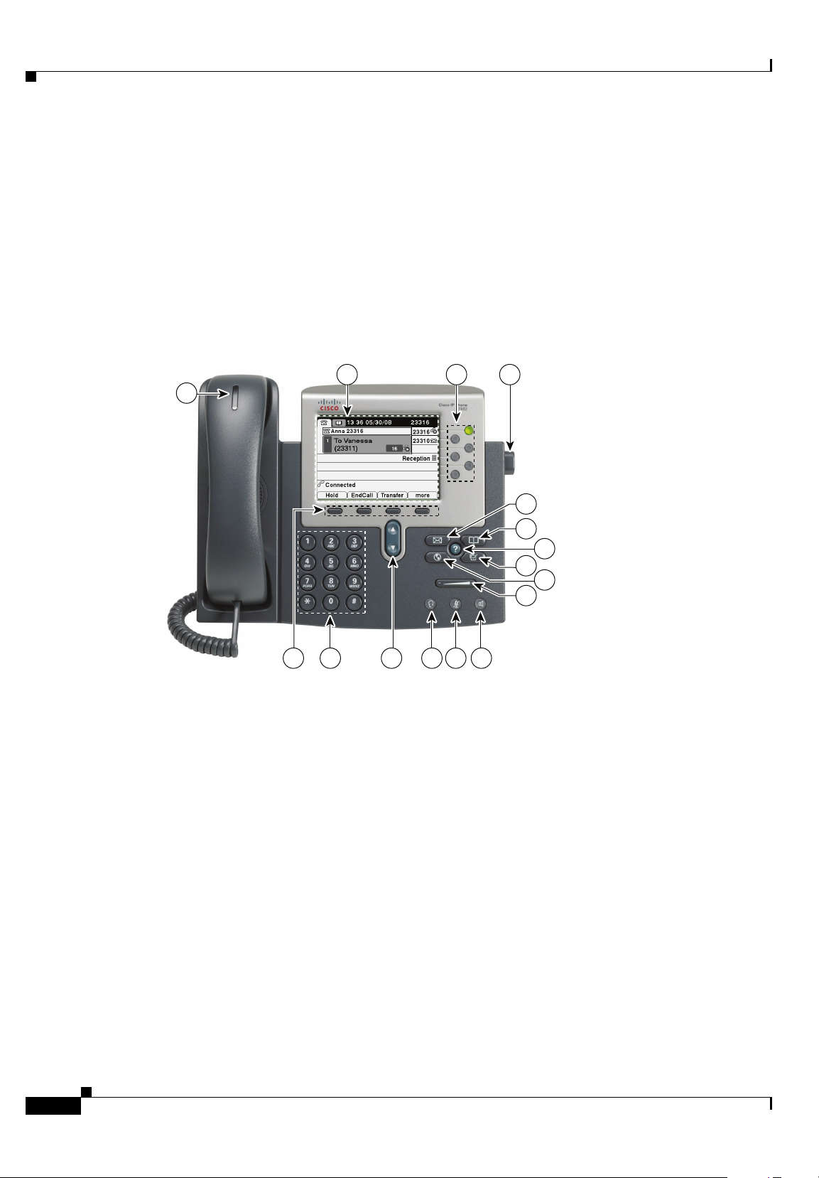
Figure 1-1 shows the main components of the Cisco Unified IP Phone 7962G.
Figure 1-2 shows the main components of the Cisco Unified IP Phone 7942G.
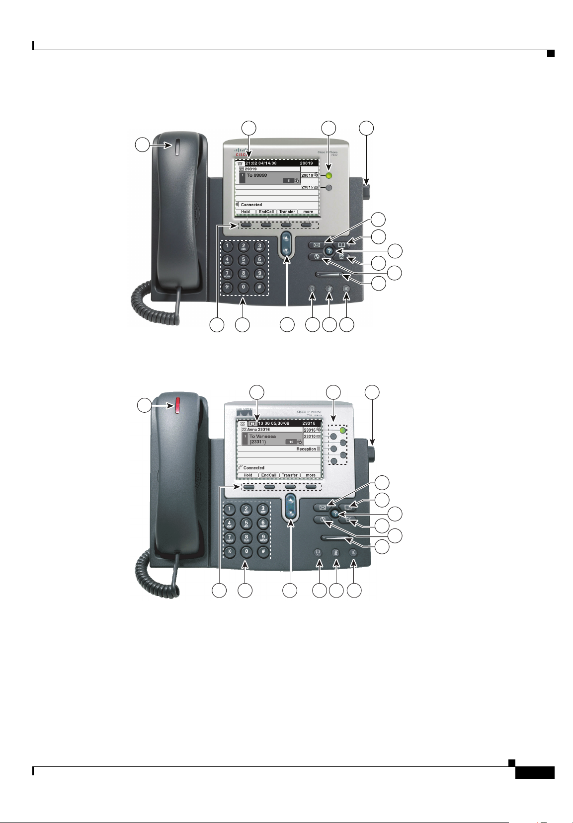
Figure 1-3 shows the main components of the Cisco Unified IP Phone 7961G and 7961G-GE.
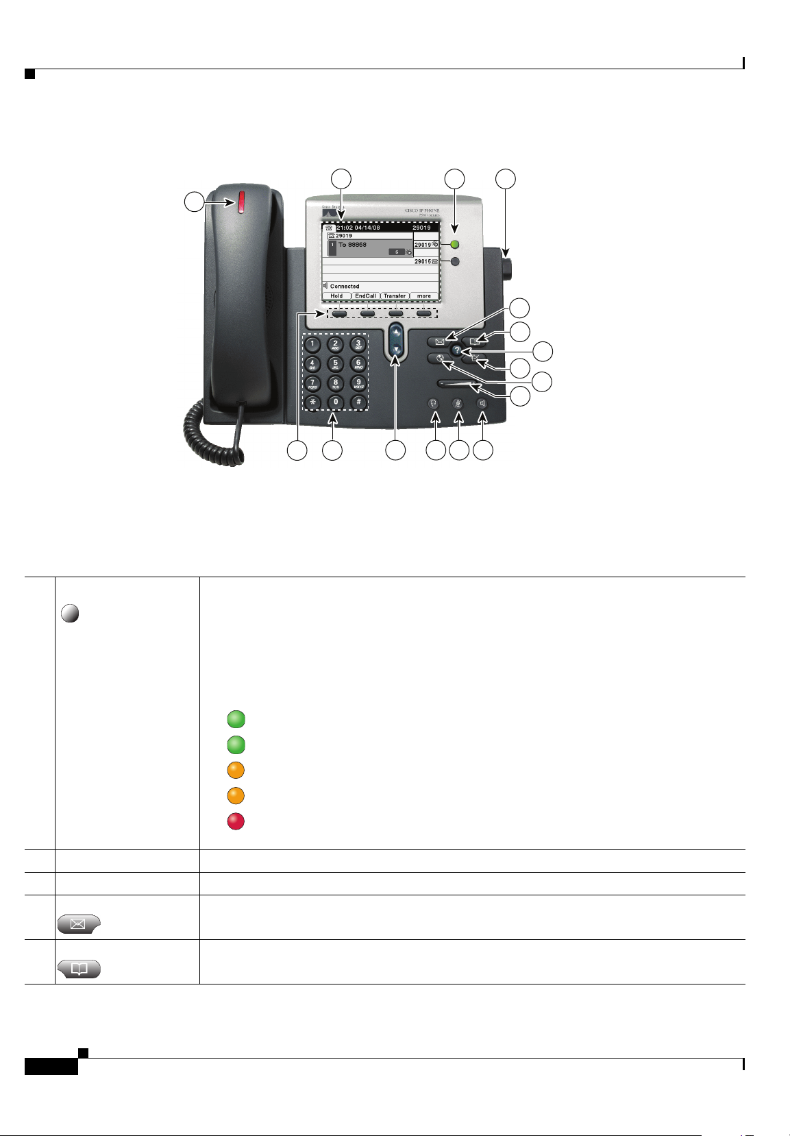
Figure 1-4 shows the main components of the Cisco Unified IP Phone 7941G and 7941G-GE.
Figure 1-1 Cisco Unified IP Phone 7962G
1-2
Cisco Unified IP Phone Administration Guide for Cisco Unified Communications Manager 8.6 (SCCP and SIP)
OL-23091-01
Page 17
Chapter 1 An Overview of the Cisco Unified IP Phones
Understanding the Cisco Unified IP Phone 7962G and 7942G 7962G, 7942G, 7961G, 7961G-GE, 7941G, and 7941G-GE
Figure 1-2 Cisco Unified IP Phone 7942G
2
13
16
4
5
7
9
101112131415
Figure 1-3 Cisco Unified IP Phone 7961G and 7961G-GE
16
2
1
1
3
6
8
187004
OL-23091-01
4
5
6
7
8
9
101112131415
Cisco Unified IP Phone Administration Guide for Cisco Unified Communications Manager 8.6 (SCCP and SIP)
186845
1-3
Page 18
Chapter 1 An Overview of the Cisco Unified IP Phones
Understanding the Cisco Unified IP Phone 7962G and 7942G 7962G, 7942G, 7961G, 7961G-GE, 7941G, and 7941G-GE
Figure 1-4 Cisco Unified IP Phone 7941G and 7941G-GE
2
16
13
1
101112131415
4
5
6
7
8
9
186846
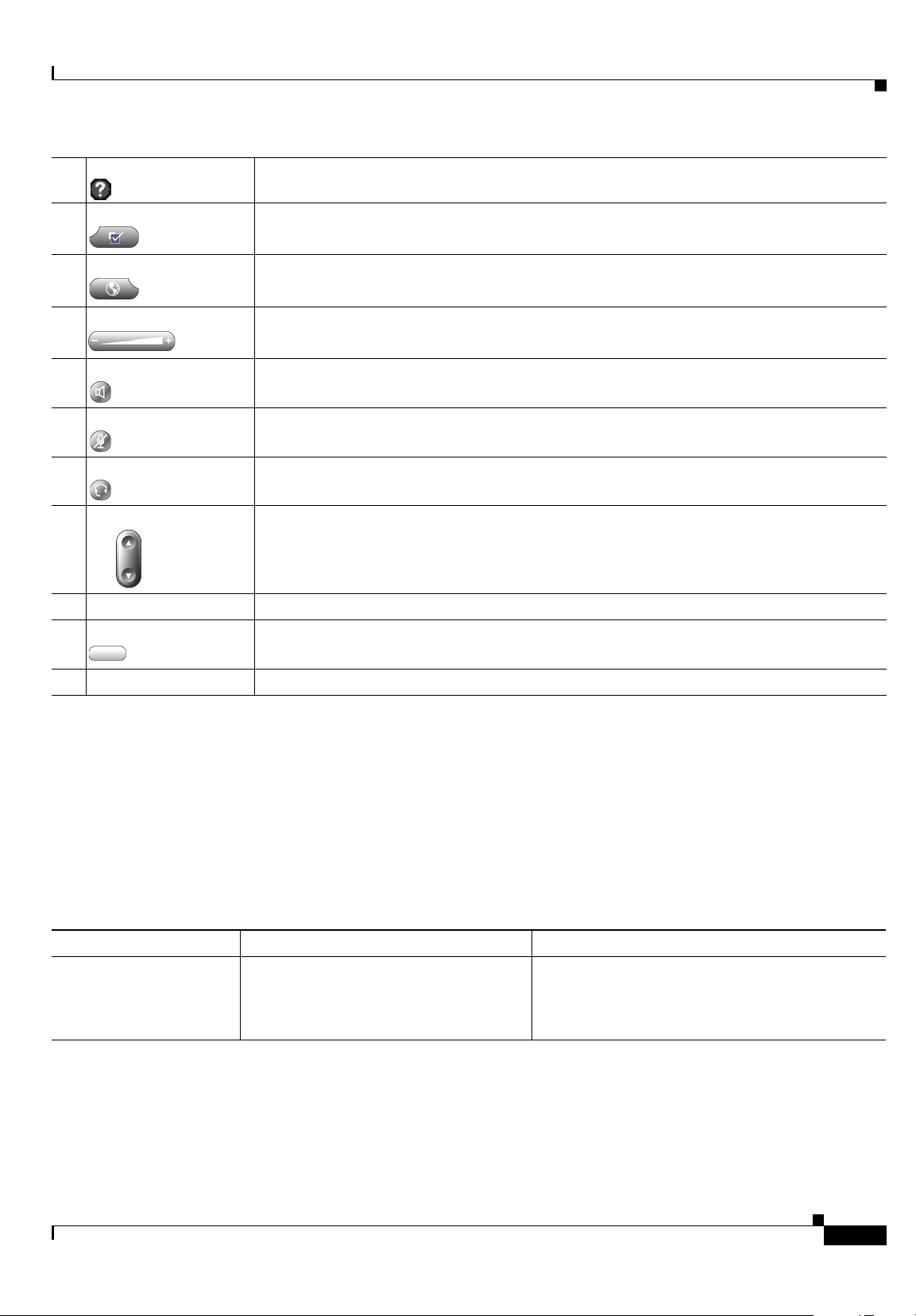
Table 1-1 describes the buttons on the Cisco Unified IP Phone 7962G and 7942G.
Ta b l e 1-1 Features on the Cisco Unified IP Phones 7962G, 7942G, 7961G, 7961G-GE, 7941G, and 7941 G-GE
1 Programmable buttons Depending on configuration, programmable buttons provide access to:
• Phone lines (line buttons)
• Speed-dial numbers (speed-dial buttons, including the BLF speed-dial feature)
• Web-based services (for example, a Personal Address Book [PAB] button)
• Phone features (for example, a Privacy button)
The buttons illuminate to indicate status:
Green, steady—Active call
Green, flashing—Held call
Amber, steady—Privacy in use
Amber, flashing—Incoming call
Red steady—Remote line in use (shared line, BLF status, or active Mobile Connect
call)
2 Phone screen Shows phone features.
3 Footstand button Allows you to adjust the angle of the phone base.
4 Messages button Dials your voice-message service automatically (varies by service).
5 Directories button Opens/closes the Directories menu. Use the button to access call logs and directories.
1-4
Cisco Unified IP Phone Administration Guide for Cisco Unified Communications Manager 8.6 (SCCP and SIP)
OL-23091-01
Page 19
Chapter 1 An Overview of the Cisco Unified IP Phones
What Networking Protocols are Used?
6 Help button Activates the Help menu.
7 Settings button Opens/closes the Settings menu. Use the button to control phone screen contrast and ring
sounds.
8 Services button Opens/closes the Services menu.
9 Volume button Controls the handset, headset, and speakerphone volume (off-hook) and the ringer volume
(on-hook).
10 Speaker button Toggles the speakerphone on or off. When the speakerphone is on, the button is lit.
11 Mute button Toggles the Mute feature on or off. When Mute is on, the button is lit.
12 Headset button Toggles the headset on or off. When the headset is on, the button is lit.
13 Navigation button Allows you to scroll through menus and highlight items. When the phone is on-hook, displays
phone numbers from your Placed Calls log.
14 Keypad Allows you to dial phone numbers, enter letters, and choose menu items.
15 Softkey buttons Each activates a softkey option (displayed on your phone screen).
16 Handset light strip Indicates an incoming call or new voice message.
What Networking Protocols are Used?
Cisco Unified IP Phones support several industry-standard and Cisco networking protocols required for
voice communication.
IP Phones support.
Ta b l e 1-2 Supported Networking Protocols on the Cisco Unified IP Phones
Networking Protocol Purpose Usage Notes
Bootstrap Protocol
(BootP)
BootP enables a network device such as
the Cisco Unified IP Phones to discover
certain startup information, such as its IP
address.
Table 1-2 provides an overview of the networking protocols that the Cisco Unified
If you use BootP to assign IP addresses to the Cisco
Unified
shows “Yes” in the network configuration settings
on the phone.
IP Phones, the BOOTP Server option
OL-23091-01
Cisco Unified IP Phone Administration Guide for Cisco Unified Communications Manager 8.6 (SCCP and SIP)
1-5
Page 20

Chapter 1 An Overview of the Cisco Unified IP Phones
What Networking Protocols are Used?
Table 1-2 Supported Networking Protocols on the Cisco Unified IP Phones (continued)
Networking Protocol Purpose Usage Notes
Cisco Discovery Protocol
(CDP)
CDP is a device-discovery protocol that
runs on all Cisco-manufactured
equipment.
Using CDP, a device advertises its
existence to other devices and receives
The Cisco Unified IP Phones use CDP to
communicate information such as auxiliary VLAN ID,
per port power management details, and Quality of
Service (QoS) configuration information with the
Cisco Catalyst switch.
information about other devices in the
network.
Cisco Peer-to-Peer
Distribution Protocol
(CPPDP)
CPPDP is a Cisco proprietary protocol
used to form a peer-to-peer hierarchy of
devices. CPPDP is also used to copy
CPPDP is used by the Peer Firmware Sharing
feature.
firmware or other files from peer devices
to neighboring devices.
Dynamic Host
Configuration Protocol
(DHCP)
DHCP dynamically allocates and assigns
an IP address to network devices.
DHCP enables you to connect an IP Phone
into the network and have the phone
become operational without your needing
to manually assign an IP address or to
configure additional network parameters.
DHCP is enabled by default. If disabled, you must
manually configure the IP address, subnet mask,
gateway, and a TFTP server on each phone locally.
Cisco recommends that you use DHCP custom
option 150. With this method, you configure the
TFTP server IP address as the option value. For
additional supported DHCP configurations, see
Dynamic Host Configuration Protocol and
Cisco TFTP in the Cisco Unified Communications
Manager System Guide.
Hypertext Transfer
Protocol (HTTP)
HTTP is the standard way of transferring
information and moving documents across
the Internet and the web.
Cisco Unified IP Phones use HTTP for the XML
services and for troubleshooting purposes.
Cisco Unified IP Phones do not support the use of
IPv6 addresses in the URL. You cannot use a literal
IPv6 address in the URL or a hostname that maps to
an IPv6 address.
Hypertext Transfer
Protocol Secure (HTTPS)
Hypertext Transfer Protocol Secure
(HTTPS) is a combination of the
Hypertext Transfer Protocol with the
SSL/TLS protocol to provide encryption
Web applications with both HTTP and HTTPS
support have two URLs configured. Cisco Unified
IP Phones that support HTTPS choose the HTTPS
URL out of the two URLs.
and secure identification of servers.
IEEE 802.1X The IEEE 802.1X standard defines a
client-server-based access control and
authentication protocol that restricts
unauthorized clients from connecting to a
LAN through publicly accessible ports.
Until the client is authenticated, 802.1X
access control allows only Extensible
Authentication Protocol over LAN
(EAPOL) traffic through the port to which
The Cisco Unified IP Phones implement the IEEE
802.1X standard by providing support for the
following authentication methods: EAP-FAST,
EAP-TLS, and EAP-MD5.
When 802.1X authentication is enabled on the
phone, you should disable the PC port and voice
VLAN. See
Supporting 802.1X Authentication on
Cisco Unified IP Phones, page 1-19 for additional
information.
the client is connected. After
authentication is successful, normal traffic
can pass through the port.
1-6
Cisco Unified IP Phone Administration Guide for Cisco Unified Communications Manager 8.6 (SCCP and SIP)
OL-23091-01
Page 21

Chapter 1 An Overview of the Cisco Unified IP Phones
What Networking Protocols are Used?
Table 1-2 Supported Networking Protocols on the Cisco Unified IP Phones (continued)
Networking Protocol Purpose Usage Notes
Internet Protocol (IP) IP is a messaging protocol that addresses
and sends packets across the network.
To communicate using IP, network devices must
have an assigned IP address, subnet, and gateway.
IP addresses, subnets, and gateway identifications
are automatically assigned if you are using the
Cisco Unified
IP Phones with Dynamic Host
Configuration Protocol (DHCP). If you are not
using DHCP, you must manually assign these
properties to each phone locally. The Cisco Unified
IP Phones support concurrent IPv4 and IPv6
addresses. Configure the IP addressing mode (IPv4
only, IPv6 only, and both IPv4 and IPv6) in Cisco
Unified Communications Manager Administration.
For more information, see
6 (IPv6) in the Cisco Unified Communications
Manager Features and Services Guide.
Link Layer Discovery
Protocol (LLDP)
LLDP is a standardized network discovery
protocol (similar to CDP) that some Cisco
The Cisco Unified IP Phones support LLDP on the
PC port.
and third-party devices support.
Link Layer Discovery
Protocol-Media Endpoint
Devices (LLDP-MED)
LLDP-MED is an extension of the LLDP
standard developed for voice products.
The Cisco Unified IP Phones support LLDP-MED
on the SW port to communicate information such as:
• Voice VLAN configuration
• Device discovery
Internet Protocol Version
Real-Time Transport
Protocol (RTP)
Real-Time Control
Protocol (RTCP)
Session Description
Protocol (SDP)
RTP is a standard protocol for transporting
real-time data, such as interactive voice
and video, over data networks.
RTCP works in conjunction with RTP to
provide Quality of Service (QoS) data
(such as jitter, latency, and round trip
delay) on RTP streams.
SDP is the portion of the SIP protocol that
determines which parameters are available
during a connection between two
endpoints. Conferences are established by
using only the SDP capabilities that are
supported by all endpoints in the
conference.
• Power management
• Inventory management
For more information about LLDP-MED support,
see the LLDP-MED and Cisco Discovery Protocol
white paper:
http://www.cisco.com/en/US/tech/tk652/tk701/tech
nologies_white_paper0900aecd804cd46d.shtml
Cisco Unified IP Phones use the RTP protocol to
send and receive real-time voice traffic from other
phones and gateways.
RTCP is disabled by default, but you can enable it
on a per phone basis by using Cisco
Unified
Communications Manager. For more information,
see
Network Configuration Menu, page 4-34.
SDP capabilities, such as codec types, DTMF
detection, and comfort noise, are normally
configured on a global basis by Cisco Unified
Communications Manager or Media Gateway in
operation. Some SIP endpoints may allow these
parameters to be configured on the endpoint itself.
OL-23091-01
Cisco Unified IP Phone Administration Guide for Cisco Unified Communications Manager 8.6 (SCCP and SIP)
1-7
Page 22

Chapter 1 An Overview of the Cisco Unified IP Phones
What Networking Protocols are Used?
Table 1-2 Supported Networking Protocols on the Cisco Unified IP Phones (continued)
Networking Protocol Purpose Usage Notes
Session Initiation Protocol
(SIP)
SIP is the Internet Engineering Task Force
(IETF) standard for multimedia
conferencing over IP. SIP is an
ASCII-based application-layer control
protocol (defined in RFC 3261) that can be
used to establish, maintain, and terminate
calls between two or more endpoints.
Like other VoIP protocols, SIP is designed to
address the functions of signaling and session
management within a packet telephony network.
Signaling allows call information to be carried
across network boundaries. Session management
provides the ability to control the attributes of an
end-to-end call.
You can configure the Cisco Unified IP Phones to
use either SIP or Skinny Client Control Protocol
(SCCP). Cisco Unified IP Phones do not support the
SIP protocol when the phones are operating in IPv6
address mode.
Skinny Client Control
Protocol (SCCP)
Transmission Control
Protocol (TCP)
SCCP includes a messaging set that allows
communications between call control
servers and endpoint clients such as IP
Phones. SCCP is proprietary to Cisco.
TCP is a connection-oriented transport
protocol.
Cisco Unified IP Phones use SCCP for call control.
You can configure the Cisco Unified
use either SCCP or Session Initiation Protocol
(SIP).
Cisco Unified IP Phones use TCP to connect to
Cisco Unified Communications Manager and to
access XML services.
Transport Layer Security
(TLS)
TLS is a standard protocol for securing
and authenticating communications.
When security is implemented, Cisco
Unified
IP Phones use the TLS protocol when
securely registering with Cisco
Unified
Communications Manager.
For more information, see Cisco Unified
Communications Manager Security Guide.
Trivial File Transfer
Protocol (TFTP)
TFTP allows you to transfer files over the
network.
On the Cisco Unified IP Phones, TFTP
enables you to obtain a configuration file
specific to the phone type.
TFTP requires a TFTP server in your network,
which can be automatically identified from the
DHCP server. If you want a phone to use a TFTP
server other than the one specified by the DHCP
server, you must manually assign the IP address of
the TFTP server by using the Network
Configuration menu on the phone.
IP Phone to
User Datagram Protocol
(UDP)
UDP is a connectionless messaging
protocol for delivery of data packets.
IPv6 Support on Cisco Unified IP Phones
The Cisco Unified IP Phones uses the internet protocol to provide voice communication over the
network. Because it uses a 32-bit address, Internet Protocol version 4 (IPv4) cannot meet the increased
demands for unique IP addresses for all devices that can connect to the internet. Internet Protocol version
Cisco Unified IP Phone Administration Guide for Cisco Unified Communications Manager 8.6 (SCCP and SIP)
1-8
For more information, see Cisco TFTP in the Cisco
Unified Communications Manager System Guide.
Cisco Unified IP Phones transmit and receive RTP
streams, which utilize UDP.
OL-23091-01
Page 23

Chapter 1 An Overview of the Cisco Unified IP Phones
6 (IPv6) is an updated version of the current Internet Protocol, IPv4. IPv6 uses a 128-bit address and
provides end-to-end security capabilities, enhanced Quality of Service (QoS), and increased number of
available IP addresses.
The Cisco Unified IP Phones support IPv4 only addressing mode, IPv6 only addressing mode, as well
as an IPv4/IPv6 dual stack addressing mode. In IPv4, you can enter each octet of the IP address on the
phone in dotted decimal notation; for example, 192.240.22.5. In IPv6, you can enter each octet of the IP
address in hexadecimal notation with each octet separated by a colon; for example,
2005:db8:0:1:ef8:9876:ba72:dc9a. The phone truncates and removes leading zeros when it displays the
IPv6 address.
Cisco Unified IP Phones support both IPv4 and an IPv6 address transparently, so users can handle all
calls on the phone to which they are accustomed. Cisco Unified IP Phones with the Skinny Call Control
Protocol (SCCP) support IPv6. Cisco Unified IP Phones with SIP do not support IPv6.
Cisco Unified IP Phones do not support URLs with IPv6 addresses in the URL. This affects all IP Phone
Service URLs, including services, directories, messages, help, and any restricted web services that
require the phone to use the HTTP protocol to validate the credentials with the Authentication URL. If
you configure Cisco Unified IP Phone services for Cisco IP Phones, you must configure the phone and
the servers that support the phone service with IPv4 addresses.
If you configure IPv6 Only as the IP Addressing Mode for phones that are running SIP, the Cisco TFTP
service overrides the IP Addressing Mode configuration and uses IPv4 Only in the configuration file.
What Features are Supported on the Cisco Unified IP Phone 7962G and 7942G?
For more information on deploying IPv6 in your Cisco Unified Communications network, see Internet
Protocol Version 6 (IPv6) in Cisco Unified Communications Manager Features and Services Guide and
Deploying IPv6 in Unified Communications Networks with Cisco Unified Communications Manager.
Related Topics
• Understanding Interactions with Other Cisco Unified IP Telephony Products, page 2-1
• Understanding the Phone Startup Process, page 2-7
• Network Configuration Menu, page 4-5
What Features are Supported on the Cisco Unified
Phone 7962G and 7942G?
IP
Cisco Unified IP Phones function much like a digital business phone, allowing you to place and receive
phone calls. In addition to traditional telephony features, the Cisco Unified IP Phones include features
that enable you to administer and monitor the phone as a network device.
This section includes the following topics:
• Feature Overview, page 1-10
• Configuring Telephony Features, page 1-10
• Configuring Network Parameters Using the Cisco Unified IP Phones, page 1-11
• Providing Users with Feature Information, page 1-11
OL-23091-01
Cisco Unified IP Phone Administration Guide for Cisco Unified Communications Manager 8.6 (SCCP and SIP)
1-9
Page 24

What Features are Supported on the Cisco Unified IP Phone 7962G and 7942G?
Feature Overview
Cisco Unified IP Phones provide traditional telephony functionality, such as call forward, call transfer,
redial, speed dial, conference call, and voice message system access. Cisco
provide a variety of other features. For an overview of the telephony features that the
Cisco
Unified IP Phones support and for tips on configuring them, see Telephony Features Available for
the Cisco Unified IP Phone, page 5-1.
With other network devices, you must configure Cisco Unified IP Phones to prepare them to access
Cisco
Unified Communications Manager and the rest of the IP network. By using DHCP, you have fewer
settings to configure on a phone, but if your network requires it, you can manually configure an IP
address, TFTP server, subnet information, and so on. For instructions on configuring the network
settings on the Cisco
Cisco Unified IP Phones can interact with other services and devices on your IP network to provide
enhanced functionality. For example, you can integrate the Cisco
Lightweight Directory Access Protocol 3 (LDAP3) standard directory to enable users to search for
coworker contact information directly from their IP Phones. You can also use XML to enable users to
access information such as weather, stocks, quote of the day, and other web-based information. For
information about configuring such services, see
Setting Up Services, page 5-28.
Finally, because the Cisco Unified IP Phones are network devices, you can obtain detailed status
information from it directly. This information can assist you with troubleshooting many problems users
might encounter when using their Cisco Unified IP Phones. See
Statistics on the Cisco Unified IP Phones for more information.
Unified IP Phones, see Configuring Settings on the Cisco Unified IP Phones.
Chapter 1 An Overview of the Cisco Unified IP Phones
Unified IP Phones also
Unified IP Phones with the corporate
Configuring Corporate Directories, page 5-24 and
Viewing Model Information, Status, and
Related Topics
• Configuring Settings on the Cisco Unified IP Phones, page 4-1
• Configuring Features, Templates, Services, and Users, page 5-1
• Troubleshooting and Maintenance, page 9-1
Configuring Telephony Features
You can modify additional settings for the Cisco Unified IP Phones from Cisco Unified
Communications Manager Administration. Use this web-based application to set up phone registration
criteria and calling search spaces, to configure corporate directories and services, and to modify phone
button templates, among other tasks. See
page 5-1 and the Cisco Unified Communications Manager documentation for additional information.
For more information about Cisco Unified Communications Manager Administration, see
Cisco
Unified Communications Manager documentation, including Cisco Unified Communications
Manager Administration Guide. You can also use the context-sensitive help available within the
application for guidance.
You can access Cisco Unified Communications Manager documentation at this location:
http://www.cisco.com/en/US/products/sw/voicesw/ps556/tsd_products_support_series_home.html
You can access Cisco Unified Communications Manager Business Edition documentation at this
location:
http://www.cisco.com/en/US/products/ps7273/tsd_products_support_series_home.html
Telephony Features Available for the Cisco Unified IP Phone,
1-10
Cisco Unified IP Phone Administration Guide for Cisco Unified Communications Manager 8.6 (SCCP and SIP)
OL-23091-01
Page 25

Chapter 1 An Overview of the Cisco Unified IP Phones
Understanding Security Features for Cisco Unified IP Phones
Related Topic
• Telephony Features Available for the Cisco Unified IP Phone, page 5-1
Configuring Network Parameters Using the Cisco Unified IP Phones
You can configure parameters such as DHCP, TFTP, and IP settings on the phone itself. You can also
obtain statistics about a current call or firmware versions on the phone.
For more information about configuring features and viewing statistics from the phone, see Configuring
Settings on the Cisco Unified IP Phones and Viewing Model Information, Status, and Statistics on the
Cisco Unified IP Phones.
Providing Users with Feature Information
If you are a system administrator, you are likely the primary source of information for Cisco Unified IP
Phone users in your network or company. To ensure that you distribute the most current feature and
procedural information, familiarize yourself with Cisco
visit the Cisco
http://www.cisco.com/en/US/products/hw/phones/ps379/tsd_products_support_series_home.html
Unified IP Phone web site:
Unified IP Phone documentation. Make sure to
From this site, you can view various user guides.
In addition to providing documentation, it is important to inform users of available Cisco Unified IP
Phone features—including those specific to your company or network—and of how to access and
customize those features, if appropriate.
For a summary of some of the key information that phone users need their system administrators to
provide, see
Appendix A, Providing Information to Users Via a Website.
Understanding Security Features for Cisco Unified IP Phones
Implementing security in the Cisco Unified Communications Manager system prevents identity theft of
the phone and Cisco
call signaling and media stream tampering.
To alleviate these threats, the Cisco IP telephony network establishes and maintains authenticated and
encrypted communication streams between a phone and the server, digitally signs files before they are
transferred to a phone, and encrypts media streams and call signaling between Cisco
The Cisco Unified IP Phone 7962G and 7942G use the Phone security profile, which defines whether
the device is nonsecure, authenticated, or encrypted. For information on applying the security profile to
the phone, see Cisco Unified Communications Manager Security Guide.
If you configure security-related settings in Cisco Unified Communications Manager Administration,
the phone configuration file contains sensitive information. To ensure the privacy of a configuration file,
you must configure it for encryption. For detailed information, see
Configuration Files in Cisco Unified Communications Manager Security Guide.
Table 1-3 shows where you can find additional information about security in this and other documents.
Unified Communications Manager server, prevents data tampering, and prevents
Unified IP Phones.
Configuring Encrypted Phone
OL-23091-01
Cisco Unified IP Phone Administration Guide for Cisco Unified Communications Manager 8.6 (SCCP and SIP)
1-11
Page 26

Understanding Security Features for Cisco Unified IP Phones
Chapter 1 An Overview of the Cisco Unified IP Phones
Ta b l e 1-3 Cisco Unified IP Phones and Cisco Unified Communications Manager Security
To p i c s
Topic Reference
Detailed explanation of security, including set
up, configuration, and troubleshooting
information for Cisco Unified
Manager and Cisco Unified
Communications
IP Phones
Security features supported on the Cisco
Unified IP Phones
See Troubleshooting Guide for Cisco Unified
Communications Manager
See Overview of Supported Security Features,
page 1-13
Restrictions regarding security features See Security Restrictions, page 1-21
Viewing a security profile name See Understanding Security Profiles, page 1-15
Identifying phone calls for which security is
implemented
See Identifying Authenticated, Encrypted, and
Protected Phone Calls, page 1-15
TLS connection See these sections:
• What Networking Protocols are Used?, page 1-5
• Adding Phones to the Cisco Unified
Communications Manager Database, page 2-8
Security and the phone startup process See Understanding the Phone Startup Process,
page 2-7
Security and phone configuration files See Adding Phones to the Cisco Unified
Communications Manager Database, page 2-8
Changing the TFTP Server 1 or TFTP Server 2
option on the phone when security is
See Table 4-2, in Network Configuration Menu,
page 4-5
implemented.
Understanding security icons in the Unified
See Unified CM Configuration Menu, page 4-19
CM1 through Unified CM5 options in the
Device Configuration Menu on the phone
Items on the Security Configuration menu that
See Security Configuration Menu, page 4-32
you access from the Device Configuration menu
on the phone
Items on the Security Configuration menu that
See Security Configuration Menu, page 4-39
you access from the Settings menu on the phone
Unlocking the CTL and ITL files See Unlocking the CTL and ITL Files section on
page 4-41
Disabling access to a phone’s web pages See Disabling and Enabling Web Page Access,
page 7-3
Deleting the CTL file from the phone See Resetting or Restoring the Cisco
Unified IP Phones, page 9-13
Resetting or restoring the phone See Resetting or Restoring the Cisco
Unified IP Phones, page 9-13
1-12
Cisco Unified IP Phone Administration Guide for Cisco Unified Communications Manager 8.6 (SCCP and SIP)
OL-23091-01
Page 27

Chapter 1 An Overview of the Cisco Unified IP Phones
Understanding Security Features for Cisco Unified IP Phones
Table 1-3 Cisco Unified IP Phones and Cisco Unified Communications Manager Security
Topics (continued)
Topic Reference
Cisco Extension Mobility HTTPS support See What Networking Protocols are Used?, page 1-5
802.1X Authentication for Cisco Unified IP
Phones
Overview of Supported Security Features
Table 1-4 provides an overview of the security features that the Cisco Unified IP Phones support. For
more information about these features and about Cisco Unified Communications Manager and
Cisco
Unified IP Phone security, see Cisco Unified Communications Manager Security Guide.
For information about current security settings on a phone, choose Settings > Security Configuration
and choose Settings > Device Configuration > Security Configuration. For more information, see
Security Configuration Menu, page 4-32.
See these sections:
• Supporting 802.1X Authentication on Cisco
Unified IP Phones, page 1-19
• Security Configuration Menu, page 4-32
• Status Menu, page 8-2
• Troubleshooting Cisco Unified IP Phone
Security, page 9-9
Note Most security features are available only if a certificate trust list (CTL) is installed on the phone. For
more information about the CTL, see
Configuring the Cisco CTL Client in Cisco Unified
Communications Manager Security Guide.
Ta b l e 1-4 Overview of Security Features
Feature Description
Image authentication Signed binary files (with the extension .sbn) prevent tampering with the firmware image
before it is loaded on a phone. Tampering with the image causes a phone to fail the
authentication process and reject the new image.
Customer-site certificate
installation
Each Cisco Unified IP Phone requires a unique certificate for device authentication. Phones
include a manufacturing installed certificate (MIC), but for additional security, you can
specify in Cisco Unified
Communications Manager Administration that a certificate be
installed by using the Certificate Authority Proxy Function (CAPF). Alternatively, you can
install a Locally Significant Certificate (LSC) from the Security Configuration menu on the
phone. See
Configuring Security on the Cisco Unified IP Phones, page 3-15 for more
information.
Device authentication Occurs between the Cisco Unified Communications Manager server and the phone when each
entity accepts the certificate of the other entity. Determines whether a secure connection
between the phone and a Cisco Unified Communications Manager should occur, and if
necessary, creates a secure signaling path between the entities by using TLS protocol. Cisco
Unified Communications Manager will not register phones unless they can be authenticated
by the Cisco Unified
Communications Manager.
OL-23091-01
Cisco Unified IP Phone Administration Guide for Cisco Unified Communications Manager 8.6 (SCCP and SIP)
1-13
Page 28

Chapter 1 An Overview of the Cisco Unified IP Phones
Understanding Security Features for Cisco Unified IP Phones
Table 1-4 Overview of Security Features (continued)
Feature Description
File authentication Validates digitally signed files that the phone downloads. The phone validates the signature to
make sure that file tampering did not occur after file creation. Files that fail authentication are
not written to Flash memory on the phone. The phone rejects such files without further
processing.
Signaling Authentication Uses the TLS protocol to validate that no tampering has occurred to signaling packets during
transmission.
Manufacturing installed
certificate
Each Cisco Unified IP Phone contains a unique manufacturing installed certificate (MIC),
which is used for device authentication. The MIC is a permanent, unique proof of identity for
the phone, and allows Cisco Unified Communications Manager to authenticate the phone.
Secure SRST reference After you configure an SRST reference for security and then reset the dependent devices in
Cisco Unified Communications Manager Administration, the TFTP server adds the SRST
certificate to the phone cnf.xml file and sends the file to the phone. A secure phone then uses
a TLS connection to interact with the SRST-enabled router.
Media encryption Uses SRTP to ensure that the media streams between supported devices proves secure and that
only the intended device receives and reads the data. Includes creating a media master key pair
for the devices, delivering the keys to the devices, and securing the delivery of the keys while
the keys are in transport.
Signaling encryption Ensures that all SCCP and SIP signaling messages that are sent between the device and the
Cisco Unified Communications Manager server are encrypted.
CAPF (Certificate Authority
Proxy Function)
Implements parts of the certificate generation procedure that are too processing-intensive for
the phone, and interacts with the phone for key generation and certificate installation. The
CAPF can be configured to request certificates from customer-specified certificate authorities
on behalf of the phone, or it can be configured to generate certificates locally.
Security profiles Defines whether the phone is nonsecure, authenticated, encrypted, or protected. See
Understanding Security Profiles, page 1-15 for more information.
Encrypted configuration
Lets you ensure the privacy of phone configuration files.
files
Optional disabling of the
web server functionality for
You can prevent access to a phone’s web page, which displays a variety of operational
statistics for the phone.
a phone
1-14
Cisco Unified IP Phone Administration Guide for Cisco Unified Communications Manager 8.6 (SCCP and SIP)
OL-23091-01
Page 29

Chapter 1 An Overview of the Cisco Unified IP Phones
Understanding Security Features for Cisco Unified IP Phones
Table 1-4 Overview of Security Features (continued)
Feature Description
Phone hardening Additional security options, which you control from Cisco Unified Communications Manager
Administration:
• Disabling PC port
• Disabling Gratuitous ARP (GARP)
• Disabling PC Voice VLAN access
• Disabling access to the Setting menus, or providing restricted access that allows access to
the User Preferences menu and saving volume changes only
• Disabling access to web pages for a phone
Note You can view current settings for the PC Port Disabled, GARP Enabled, and Voice
VLAN enabled options by looking at the phone’s Security Configuration menu. For
more information, see
Device Configuration Menu, page 4-18.
802.1X Authentication The Cisco Unified IP Phone can use 802.1X authentication to request and gain access to the
network. See
Supporting 802.1X Authentication on Cisco Unified IP Phones, page 1-19 for
more information.
Related Topics
• Understanding Security Profiles, page 1-15
• Identifying Authenticated, Encrypted, and Protected Phone Calls, page 1-15
• Security Restrictions, page 1-21
• Device Configuration Menu, page 4-18
Understanding Security Profiles
All Cisco Unified IP Phones that support Cisco Unified Communications Manager use a security profile,
which defines whether the phone is nonsecure, authenticated, or encrypted. For information about
configuring the security profile and applying the profile to the phone, see Cisco Unified Communications
Manager Security Guide.
To view the phone security mode, look at the Security Mode setting in the Security Configuration menu.
For more information, see
Related Topics
• Identifying Authenticated, Encrypted, and Protected Phone Calls, page 1-15
• Security Restrictions, page 1-21
• Device Configuration Menu, page 4-18
Security Configuration Menu, page 4-32.
Identifying Authenticated, Encrypted, and Protected Phone Calls
When security is implemented for a phone, you can identify authenticated or encrypted phone calls by
icons on the screen on the phone. You can also determine if the connected phone is secure and protected
if a security tone plays at the beginning of the call.
Cisco Unified IP Phone Administration Guide for Cisco Unified Communications Manager 8.6 (SCCP and SIP)
OL-23091-01
1-15
Page 30

Understanding Security Features for Cisco Unified IP Phones
In an authenticated call, all devices participating in the establishment of the call are trusted devices, and
authenticated by Cisco
Unified Communications Manager. When an in-progress call is authenticated,
the call progress icon to the right of the call duration timer in the phone LCD screen changes to this icon:
In an encrypted call, all devices participating in the establishment of the call are trusted devices, and
authenticated by Cisco
Unified Communications Manager. In addition, call signaling and media streams
are encrypted. An encrypted call offers a high level of security, providing integrity and privacy to the
call. When an in-progress call is being encrypted, the call progress icon to the right of the call duration
timer in the phone LCD screen changes to this icon:
Note If the call is routed through non-IP call legs, for example, PSTN, the call may be nonsecure even though
it is encrypted within the IP network and has a lock icon associated with it.
In a protected call, a security tone plays at the beginning of a call to indicate that the other connected
phone is also receiving and transmitting encrypted audio and video (if video is involved). If your call is
connected to a non-protected phone, the security tone does not play.
Chapter 1 An Overview of the Cisco Unified IP Phones
Note Protected calling is supported for connections between two phones only. Some features, such as
conference calls, shared lines, Extension Mobility, and Join Across Lines are not available when
protected calling is configured. Protected calls are not authenticated.
Related Topic
• Understanding Security Profiles, page 1-15
• Understanding Security Features for Cisco Unified IP Phones, page 1-11
• Security Restrictions, page 1-21
Establishing and Identifying Secure Conference Calls
You can initiate a secure conference call and monitor the security level of participants. A secure
conference call is established using this process:
1. A user initiates the conference from a secure phone (encrypted or authenticated security mode).
2. Cisco Unified Communications Manager assigns a secure conference bridge to the call.
3. As participants are added, Cisco Unified Communications Manager verifies the security mode of
each phone (encrypted or authenticated) and maintains the secure level for the conference.
4. The phone displays the security level of the conference call. A secure conference displays
(encrypted) or ( authenticated) icon to the right of “Conference” on the phone screen. If icon
displays, the conference is not secure.
1-16
Note There are interactions, restrictions, and limitations that affect the security level of the conference call
depending on the security mode of the participants' phones and the availability of secure conference
bridges. See Tabl e 1-5 and Tab l e 1-6 for information about these interactions.
Cisco Unified IP Phone Administration Guide for Cisco Unified Communications Manager 8.6 (SCCP and SIP)
OL-23091-01
Page 31

Chapter 1 An Overview of the Cisco Unified IP Phones
Establishing and Identifying Protected Calls
A protected call is established when your phone, and the phone on the other end, is configured for
protected calling. The other phone can be in the same Cisco IP network, or on a network outside the IP
network. Protected calls can only be made between two phones. Conference calls and other multiple-line
calls cannot be protected.
A protected call is established using this process:
1. A user initiates the call from a protected phone (protected security mode).
2. The phone displays the icon (encrypted) on the phone screen. This icon indicates that the phone
is configured for secure (encrypted) calls, but this does not mean that the other connected phone is
also protected.
3. A security tone plays if the call is connected to another protected phone, indicating that both ends
of the conversation are encrypted and protected. If the call is connected to a non-protected phone,
then the secure tone does not play.
Note Protected calling is supported for conversations between two phones. Some features, such as conference
calls, shared lines, Cisco Extension Mobility, and Join Across Lines, are not available when protected
calling is configured.
Understanding Security Features for Cisco Unified IP Phones
Call Security Interactions and Restrictions
Cisco Unified Communications Manager checks the phone security status when conferences are
established and changes the security indication for the conference or blocks the completion of the call
to maintain integrity and security in the system.
security levels when using Barge.
Ta b l e 1-5 Call Security Interactions When Using Barge
Initiator’s Phone
Security Level
Feature Used Call Security Level Results of Action
Non-secure Barge Encrypted call Call barged and identified as non-secure call
Secure (encrypted) Barge Authenticated call Call barged and identified as authenticated call
Secure
Barge Encrypted call Call barged and identified as authenticated call
(authenticated)
Non-secure Barge Authenticated call Call barged and identified as non-secure call
Table 1-6 provides information about changes to conference security levels depending on the initiator’s
phone security level, the security levels of participants, and the availability of secure conference bridges.
Table 1-5 provides information about changes to call
OL-23091-01
Cisco Unified IP Phone Administration Guide for Cisco Unified Communications Manager 8.6 (SCCP and SIP)
1-17
Page 32

Chapter 1 An Overview of the Cisco Unified IP Phones
Understanding Security Features for Cisco Unified IP Phones
Ta b l e 1-6 Security Restrictions with Conference Calls
Initiator’s Phone
Security Level
Feature Used Security Level of Participants Results of Action
Non-secure Conference Encrypted or authenticated Non-secure conference bridge
Non-secure conference
Secure (encrypted
or authenticated)
Conference At least one member is
non-secure
Secure conference bridge
Non-secure conference
Secure (encrypted) Conference All participants are encrypted Secure conference bridge
Secure encrypted level conference
Secure
(authenticated)
Conference All participants are encrypted or
authenticated
Secure conference bridge
Secure authenticated level conference
Non-secure Conference Encrypted or authenticated Only secure conference bridge is available and used
Non-secure conference
Secure (encrypted
or authenticated)
Conference Encrypted or authenticated For Cisco Unified IP Phones 7962G and 7942G:
• Only non-secure conference bridge is available
and used
• Non-secure conference
For Cisco Unified IP Phones 7961G and 7941G:
• Conference remains secure
• When one participant tries to Hold the call with
MOH, the MOH does not play.
Secure (encrypted
or authenticated)
Conference For Cisco Unified IP Phones
7962G and 7942G:
• Encrypted or secure
For Cisco Unified IP Phones
7961G and 7941G:
• Member puts call on Hold
with MOH
For Cisco Unified IP Phones 7962G and 7942G:
• Conference remains secure. When one
participant tries to hold the call with MOH, the
MOH does not play.
For Cisco Unified IP Phones 7961G and 7941G:
• No music on hold is played
• Conference remains secure.
Secure (encrypted) Join Encrypted or authenticated Secure conference bridge
Conference remains secure (encrypted or
authenticated)
Non-secure cBarge All participants are encrypted Secure conference bridge
Conference changes to non-secure
Non-secure MeetMe Minimum security level is
encrypted
Initiator receives message “Does not meet Security
Level” and the call is rejected.
1-18
Cisco Unified IP Phone Administration Guide for Cisco Unified Communications Manager 8.6 (SCCP and SIP)
OL-23091-01
Page 33

Chapter 1 An Overview of the Cisco Unified IP Phones
Understanding Security Features for Cisco Unified IP Phones
Table 1-6 Security Restrictions with Conference Calls (continued)
Initiator’s Phone
Security Level Feature Used Security Level of Participants Results of Action
Secure (encrypted) MeetMe Minimum security level is
authenticated
Secure (encrypted) MeetMe Minimum security level is
non-secure
Secure conference bridge
Conference accepts encrypted and authenticated
calls
Only secure conference bridge available and used
Conference accepts all calls
Supporting 802.1X Authentication on Cisco Unified IP Phones
These sections provide information about 802.1X support on the Cisco Unified IP Phones:
• Overview, page 1-19
• Required Network Components, page 1-19
• Best Practices—Requirements and Recommendations, page 1-20
Overview
Cisco Unified IP Phones and Cisco Catalyst switches have traditionally used Cisco Discovery Protocol
(CDP) to identify each other and determine parameters such as VLAN allocation and inline power
requirements. However, CDP is not used to identify any locally attached PCs. Therefore, Cisco Unified
IP Phones provide an EAPOL pass-through mechanism. With this mechanism, a PC locally attached to
the Cisco Unified IP Phone may pass EAPOL messages to the 802.1X authenticator in the LAN switch.
This prevents the Cisco Unified IP Phone from having to act as the authenticator, yet allows the LAN
switch to authenticate a data end point prior to accessing the network.
In conjunction with the EAPOL pass-through mechanism, Cisco Unified IP Phones provide a proxy
EAPOL-Logoff mechanism. In the event that the locally attached PC disconnects from the Cisco Unified
IP Phone, the LAN switch does see the physical link fail, because the link between the LAN switch and
the Cisco Unified IP Phone is maintained. To avoid compromising network integrity, the IP Phone sends
an EAPOL-Logoff message to the switch on behalf of the downstream PC, which triggers the LAN
switch to clear the authentication entry for the downstream PC.
The Cisco Unified IP Phones also contain an 802.1X supplicant, in addition to the EAPOL pass-through
mechanism. This supplicant allows network administrators to control the connectivity of Cisco Unified
IP Phones to the LAN switch ports. The phone 802.1X supplicant uses the EAP-FAST, EAP-TLS, and
EAP-MD5 options for network authentication.
Required Network Components
Support for 802.1X authentication on Cisco Unified IP Phones requires several components, including:
OL-23091-01
• Cisco Unified IP Phones—The phone acts as the 802.1X supplicant, which initiates the request to
access the network.
• Cisco Secure Access Control Server (ACS) (or other third-party authentication server)—The
authentication server and the phone must both be configured with a shared secret that is used to
authenticate the phone.
Cisco Unified IP Phone Administration Guide for Cisco Unified Communications Manager 8.6 (SCCP and SIP)
1-19
Page 34

Understanding Security Features for Cisco Unified IP Phones
• Cisco Catalyst Switch (or other third-party switch)—The switch must support 802.1X, so it can act
as the authenticator and pass the messages between the phone and the authentication server. When
the exchange completes, the switch grants or denies the phone access to the network.
Best Practices—Requirements and Recommendations
• Enable 802.1X Authentication—If you want to use the 802.1X standard to authenticate Cisco
Unified IP Phones, be sure that you have properly configured the other components before enabling
it on the phone. See
• Configure PC Port—The 802.1X standard does not take into account the use of VLANs and thus
recommends that only a single device should authenticate to a specific switch port. However, some
switches (including Cisco Catalyst switches) support multi-domain authentication. The switch
configuration determines whether you can connect a PC to the phone’s PC port.
–
Enabled—If you are using a switch that supports multi-domain authentication, you can enable
the PC port and connect a PC to it. In this case, Cisco Unified IP Phones support proxy
EAPOL-Logoff to monitor the authentication exchanges between the switch and the attached
PC. For more information about IEEE 802.1X support on the Cisco Catalyst switches, see the
Cisco Catalyst switch configuration guides at:
http://www.cisco.com/en/US/products/hw/switches/ps708/tsd_products_support_series_home.
html
802.1X Authentication and Status, page 4-44 for more information.
Chapter 1 An Overview of the Cisco Unified IP Phones
–
Disabled—If the switch does not support multiple 802.1X-compliant devices on the same port,
you should disable the PC Port when 802.1X authentication is enabled. See
Security
Configuration Menu, page 4-32 for more information. If you do not disable this port and
subsequently attempt to attach a PC to it, the switch will deny network access to both the phone
and the PC.
• Configure Voice VLAN—Because the 802.1X standard does not account for VLANs, you should
configure this setting based on the switch support.
–
Enabled—If you are using a switch that supports multi-domain authentication, you can continue
to use the voice VLAN.
–
Disabled—If the switch does not support multi-domain authentication, disable the Voice VLAN
and consider assigning the port to the native VLAN. See
Security Configuration Menu,
page 4-32 for more information.
• Enter MD5 Shared Secret—If you disable 802.1X authentication or perform a factory reset on the
phone, the previously configured MD5 shared secret is deleted. See
802.1X Authentication and
Status, page 4-44 for more information.
1-20
Cisco Unified IP Phone Administration Guide for Cisco Unified Communications Manager 8.6 (SCCP and SIP)
OL-23091-01
Page 35

Chapter 1 An Overview of the Cisco Unified IP Phones
Reducing Power Consumption on the Phones
Security Restrictions
A user cannot barge into an encrypted call if the phone that is used to barge is not configured for
encryption. When barge fails in this case, a reorder (fast busy) tone plays on the phone on which the user
initiated the barge.
If the initiator phone is configured for encryption, the barge initiator can barge into an authenticated or
nonsecure call from the encrypted phone. After the barge occurs, Cisco
Manager classifies the call as nonsecure.
If the initiator phone is configured for encryption, the barge initiator can barge into an encrypted call,
and the phone indicates that the call is encrypted.
A user can barge into an authenticated call, even if the phone that is used to barge is nonsecure. The
authentication icon continues to appear on the authenticated devices in the call, even if the initiator
phone does not support security.
Reducing Power Consumption on the Phones
Unified Communications
The Cisco Unified IP Phones support Cisco EnergyWise (EW). EnergyWise is also known as Power
Save Plus. When your network contains an EnergyWise controller, you can configure these phones to
sleep (power down) and wake (power up) on a schedule to reduce your power consumption. The phone
is powered with switch's Power over Ethernet (PoE) port instead of the power adapter.
You set up each phone to enable or disable the EnergyWise settings. You can also configure EnergyWise
parameters on the enterprise and common phone configuration. If EnergyWise is enabled, you configure
a sleep and wake time, as well as other parameters. These parameters are sent to the phone as part of the
phone configuration XML file.
The switch administrator can wake the phone up before the scheduled time. For more information on
powering up the phones from the switch, see the switch documentation.
Overview of Configuring and Installing Cisco Unified IP Phones
When deploying a new IP telephony system, system administrators and network administrators must
complete several initial configuration tasks to prepare the network for IP
information and a checklist for setting up and configuring a complete Cisco IP telephony network, see
System Configuration Overview in Cisco Unified Communications Manager System Guide.
After you have set up the IP telephony system and configured system-wide features in Cisco Unified
Communications Manager, you can add Cisco Unified IP Phones to the system.
The following topics provide an overview of procedures for adding Cisco Unified IP Phones to your
network:
• Configuring Cisco Unified IP Phones in Cisco Unified Communications Manager, page 1-21
• Installing Cisco Unified IP Phones, page 1-25
telephony service. For
Configuring Cisco Unified IP Phones in Cisco Unified Communications Manager
To add phones to the Cisco Unified Communications Manager database, you can use:
Cisco Unified IP Phone Administration Guide for Cisco Unified Communications Manager 8.6 (SCCP and SIP)
OL-23091-01
1-21
Page 36

Chapter 1 An Overview of the Cisco Unified IP Phones
Overview of Configuring and Installing Cisco Unified IP Phones
• Auto-registration
• Cisco Unified Communications Manager Administration
• Bulk Administration Tool (BAT)
• BAT and the Tool for Auto-Registered Phones Support (TAPS)
For more information about these choices, see Adding Phones to the Cisco Unified Communications
Manager Database, page 2-8.
For general information about configuring phones in Cisco Unified Communications Manager, see
Cisco Unified IP Phones in Cisco Unified Communications Manager System Guide.
Checklist for Configuring the Cisco Unified IP Phones in Cisco Unified Communications Manager Administrations
Table 1-7 provides an overview and checklist of configuration tasks for the Cisco Unified IP Phones in
Cisco Unified Communications Manager Administration. The list presents a suggested order to guide
you through the phone configuration process. Some tasks are optional, depending on your system and
user needs. For detailed procedures and information, see the sources in the list.
1-22
Cisco Unified IP Phone Administration Guide for Cisco Unified Communications Manager 8.6 (SCCP and SIP)
OL-23091-01
Page 37

Chapter 1 An Overview of the Cisco Unified IP Phones
Overview of Configuring and Installing Cisco Unified IP Phones
Ta b l e 1-7 Checklist for Configuring the Cisco Unified IP Phone 7962G and 7942G in Cisco Unified Communications
Manager
Task Purpose For More Information
1. Gather the following information about the phone:
See these sections:
• Phone Model
• MAC address
• Physical location of the phone
• Name or user ID of phone user
• Device pool
• Partition, calling search space, and location
information
• Number of lines and associated directory numbers
(DNs) to assign to the phone
• Cisco Unified Communications Manager user to
associate with the phone
• Phone usage information that affects phone
button template, softkey template, phone features,
IP Phone services, or phone applications
Provides list of configuration requirements for setting
up phones.
Identifies preliminary configuration that you need to
perform before configuring individual phones, such as
phone button templates or softkey templates.
2. Customize phone button templates (if required).
Changes the number of line buttons, speed-dial
buttons, Service URL buttons, or adds a Privacy
button to meet user needs.
You must specify a service URL with an IPv4 address.
3. Add and configure the phone by completing the
required fields in the Phone Configuration window.
Required fields are indicated by an asterisk (*) next to
the field name; for example, MAC address and device
pool.
Adds the device with its default settings to the Cisco
Unified Communications Manager database.
4. Add and configure directory numbers (lines) on the
phone by completing the required fields in the
Directory Number Configuration window. Required
fields are indicated by an asterisk (*) next to the field
name; for example, directory number and presence
group.
Adds primary and secondary directory numbers and
features associated with directory numbers to the
phone.
• See Cisco Unified Communications Manager System
Guide,
• See Telephony Features Available for the Cisco
Cisco Unified IP Phones.
Unified IP Phone, page 5-1.
See these sections:
• Cisco Communications Manager Administration
Guide,
• Modifying Phone Button Templates, page 5-25.
Phone Button Template Configuration.
See Cisco Communications Manager Administration
Guide,
Cisco Unified IP Phone Configuration.
For information about Product Specific Configuration
fields, see “?” Button Help in the Phone Configuration
window.
See these sections:
• See Cisco Unified Communications Manager
Administration Guide,
Directory Number
Configuration.
• See Telephony Features Available for the Cisco
Unified IP Phone, page 5-1.
OL-23091-01
Cisco Unified IP Phone Administration Guide for Cisco Unified Communications Manager 8.6 (SCCP and SIP)
1-23
Page 38

Chapter 1 An Overview of the Cisco Unified IP Phones
Overview of Configuring and Installing Cisco Unified IP Phones
Table 1-7 Checklist for Configuring the Cisco Unified IP Phone 7962G and 7942G in Cisco Unified Communications
Manager (continued)
Task Purpose For More Information
5. Customize softkey templates.
Adds, deletes, or changes order of softkey features
that display on the user’s phone to meet feature usage
See Cisco Unified Communications Manager
Administration Guide,
Softkey Template Configuration.
See Configuring Softkey Templates, page 5-27.
needs.
6. Configure speed-dial buttons and assign speed-dial
numbers (optional).
Adds speed-dial buttons and numbers.
Note Users can change speed-dial settings on their
See Cisco Unified Communications Manager
Administration Guide,
Cisco Unified IP Phone
Configuration chapter, Configuring Speed-Dial Buttons
section.
phones by using Cisco Unified CM User
Options.
7. Configure Cisco Unified IP Phone services and assign
services (optional).
Provides IP Phone services.
Note Users can add or change services on their
phones by using the Cisco Unified CM User
See these sections:
• See Cisco Communications Manager
Administration Guide,
Cisco Unified IP Phone
Services Configuration.
• See Setting Up Services, page 5-28.
Options.
Note You must specify a service URL with an IPv4
address.
8. Assign services to phone buttons (optional).
Provides single button access to an IP Phone service
or URL.
9. Add user information by configuring required fields.
Required fields are indicated by an asterisk (*); for
example, User ID and last name.
Note Assign a password (for User Options web
pages) and PIN (for Extension Mobility and
Personal Directory).
Adds user information to the global directory for
Cisco Unified
Communications Manager.
See Cisco Unified Communications Manager
Administration Guide,
Cisco Unified IP Phone
Configuration.
See Cisco Unified Communications Manager
Administration Guide,
End User Configuration.
See Adding Users to Cisco Unified Communications
Manager, page 5-28.
Note If your company uses a Lightweight Directory
Access Protocol (LDAP) directory to store
information on users, you can install and
configure Cisco
your existing LDAP directory, see
Unified Communications to use
Configuring
Corporate Directories, page 5-24.
Note If you want to add both the phone and user to the
Cisco Unified Communications Manager
database at the same time, see the
User/Phone
Add Configuration chapter in the Cisco Unified
Communications Manager Administration
Guide.
1-24
Cisco Unified IP Phone Administration Guide for Cisco Unified Communications Manager 8.6 (SCCP and SIP)
OL-23091-01
Page 39

Chapter 1 An Overview of the Cisco Unified IP Phones
Overview of Configuring and Installing Cisco Unified IP Phones
Table 1-7 Checklist for Configuring the Cisco Unified IP Phone 7962G and 7942G in Cisco Unified Communications
Manager (continued)
Task Purpose For More Information
10. Add a user to a user group.
Assigns to users a common list of roles and
permissions that apply to all users in a user group.
Administrators can manage user groups, roles, and
permissions to control the level of access (and,
See Cisco Unified Communications Manager
Administration Guide:
• End User Configuration.
• User Group Configuration.
therefore, the level of security) for system users.
11. Associate a user with a phone (optional).
Provides users with control over their phone such a
See Cisco Unified Communications Manager
Administration Guide,
End User Configuration.
forwarding calls or adding speed-dial numbers or
services.
Note Some phones, such as those in conference
rooms, do not have an associated user.
Installing Cisco Unified IP Phones
After you have added the phones to the Cisco Unified Communications Manager database, you can
complete the phone installation. You can install the phones at the desired location, or you can give the
phone users the information they need to do perform the installation. The Cisco
Installation Guide, which is available at
phone handset, cables, and other accessories.
Note Before you install a phone, even if it is new, upgrade the phone to the current firmware image. For
information about upgrading, see the Readme file for your phone, which is located at:
http://www.cisco.com/cgi-bin/tablebuild.pl/ip-7900ser
After the phone is connected to the network, the phone startup process begins, and the phone registers
with Cisco
Unified Communications Manager. To finish installing the phone, configure the network
settings on the phone depending on whether you enable or disable DHCP service.
If you use auto-registration, you need to update the specific configuration information for the phone such
as associating the phone with a user, changing the button table, or directory number.
Checklist for Installing the Cisco Unified IP Phones
Table 1-8 provides an overview and checklist of installation tasks for the Cisco Unified IP Phones. The
list presents a suggested order to guide you through the phone installation. Some tasks are optional,
depending on your system and user needs. For detailed procedures and information, see the sources in
the list.
http://www.cisco.com, provides directions for connecting the
Unified IP Phone
OL-23091-01
Cisco Unified IP Phone Administration Guide for Cisco Unified Communications Manager 8.6 (SCCP and SIP)
1-25
Page 40

Chapter 1 An Overview of the Cisco Unified IP Phones
Overview of Configuring and Installing Cisco Unified IP Phones
Ta b l e 1-8 Checklist for Installing the Cisco Unified IP Phones
Task Purpose For More Information
1. Choose the power source for the phone:
• Power over Ethernet (PoE)
• External power supply
See Providing Power to the Cisco Unified IP
Phones, page 2-3.
Determines how the phone receives power.
2. Assemble the phone, adjust phone placement, and connect the
network cable.
Locates and installs the phone in the network.
See Installing the Cisco Unified IP Phones,
page 3-6.
See Feature Key Capacity Increase for Cisco
Unified IP Phones, page 3-10.
3. Add a Cisco Unified IP Phone Expansion Module:
Adds the device with its default settings to the Cisco Unified
See Attaching a Cisco Unified IP Phone
Expansion Module, page 3-9.
Communications Manager database.
Extends functionality of a Cisco Unified IP Phone 7962G by
adding 14 (7914) or 24 (7915 and 7916) line appearances or
speed-dial numbers.
Extends functionality of a Cisco Unified IP Phones 7961G and
7961G-GE by adding 14 (7914) line appearances or speed-dial
numbers.
Note Cisco Unified IP Phone Expansion Module 7914 is not
supported on the Cisco Unified IP Phones 7942G,
7941G, and 7941G-GE.
Note Cisco Unified IP Phone Expansion Modules 7915 and
7916 are not supported on the Cisco Unified IP Phones
7942G, 7961G, 7961G-GE, 7941G, and 7941G-GE.
Note Up to 54 keys can be configured for Cisco Unified IP
Phones 7962G.
4. Monitor the phone startup process.
Adds primary and secondary directory numbers and features
associated with directory numbers to the phone.
Verifies that phone is configured properly.
See Verifying the Phone Startup Process,
page 3-14.
1-26
Cisco Unified IP Phone Administration Guide for Cisco Unified Communications Manager 8.6 (SCCP and SIP)
OL-23091-01
Page 41

Chapter 1 An Overview of the Cisco Unified IP Phones
Overview of Configuring and Installing Cisco Unified IP Phones
Table 1-8 Checklist for Installing the Cisco Unified IP Phones (continued)
Task Purpose For More Information
5. If you are configuring the network settings on the phone for an
IPv4 network, you can set up an IP address for the phone by
either using DHCP or manually entering an IP address.
See Configuring Startup Network Settings,
page 3-15.
See Network Configuration Menu, page 4-5.
Using DHCP—To enable DHCP and allow the DHCP server to
automatically assign an IP address to the Cisco Unified IP Phone
and direct the phone to a TFTP server, choose Settings >
Network Configuration> IPv4 Configuration and configure
the following:
• To enable DHCP, set DHCP Enabled to Yes . DHCP is
enabled by default.
• To use an alternate TFTP server, set Alternate TFTP Server
to Yes , and enter the IP address for the TFTP Server.
Note Consult with the network administrator to determine
whether you need to assign an alternative TFTP server
instead of using the TFTP server assigned by DHCP.
Without DHCP—You must configure the IP address, subnet
mask, TFTP server, and default router locally on the phone,
choose Settings > Network Configuration> IPv4
Configuration:
To disable DHCP and manually set an IP address:
a. To disable DHCP, set DHCP Enabled to No.
b. Enter the static IP address for phone.
c. Enter the subnet mask.
d. Enter the default router IP addresses.
e. Set Alternate TFTP Server to Yes , and enter the IP address
for TFTP Server 1.
You must also enter the domain name where the phone resides by
Choosing Settings > Network Configuration.
The Cisco Unified IP Phones support having both IPv4 and an
IPv6 address concurrently. You can configure Cisco Unified
Communications Manager to support IPv4 addresses only, IPv6
addresses only, or support both IPv4/IPv6 addresses.
OL-23091-01
Cisco Unified IP Phone Administration Guide for Cisco Unified Communications Manager 8.6 (SCCP and SIP)
1-27
Page 42

Chapter 1 An Overview of the Cisco Unified IP Phones
Overview of Configuring and Installing Cisco Unified IP Phones
Table 1-8 Checklist for Installing the Cisco Unified IP Phones (continued)
Task Purpose For More Information
6. If you are configuring the network settings on the phone for an
IPv6 network, you can set up an IP address for the phone by
either using DHCPv6 or by manually entering an IP address.
See Configuring Startup Network Settings,
page 3-15.
See Network Configuration Menu, page 4-5.
Using DHCPv6—To enable DHCPv6 and allow the DHCPv6
server to automatically assign an IP address to the Cisco Unified
IP Phone and direct the phone to a TFTP server, choose Settings
> Network Configuration> IPv6 Configuration and configure
the following:
• To enable DHCPv6, set DHCPv6 to Ye s. DHCPv6 is
enabled by default.
• To use an alternate TFTP server, set IPv6 Alternate TFTP
Server to Yes , and enter the IP address for IPv6 TFTP Server
1.
Note Consult with the network administrator if you need to
assign an alternate TFTP server instead of using the
TFTP server assigned by DHCP.
Without DHCP—You must configure the IP address, subnet
mask and TFTP server locally on the phone, choose Settings >
Network Configuration> IPv6 Configuration:
To disable DHCP and manually set an IP address:
a. To disable DHCPv6, set DHCPv6 to No.
b. Enter the static IP address for phone.
c. Enter the IPv6 prefix length.
d. Set IPv6 Alternate TFTP Server to Yes , and enter IP address
for IPv6 TFTP Server 1.
You must also enter the domain name where the phone resides by
Choosing Settings > Network Configuration.
Note The Cisco Unified IP Phones support having both IPv4
and an IPv6 address concurrently. You can configure
Cisco Unified Communications Manager to support IPv4
devices only, IPv6 devices only, or to support both IPv4
and IPv6 devices concurrently.
7. Set up security on the phone.
Provides protection against data tampering threats and identity
theft of phones.
8. Make calls with the Cisco Unified IP Phones.
Verifies that the phone and features work correctly.
9. Provide information to end users about how to use their phones
and how to configure their phone options.
See Configuring Security on the Cisco Unified
IP Phones, page 3-15.
See Cisco Unified IP Phone 7962G, 7942G,
7961G, 7961G-GE, 7941G, and 7941G-GE
User Guide.
See Appendix A, Providing Information to
Users Via a Website.
1-28
Ensures that users have adequate information to successfully use
their Cisco Unified
Cisco Unified IP Phone Administration Guide for Cisco Unified Communications Manager 8.6 (SCCP and SIP)
IP Phones.
OL-23091-01
Page 43

CHAP T ER
2
Preparing to Install the Cisco Unified IP Phones on Your Network
Cisco Unified IP Phones enable you to communicate by using voice over a data network. To provide this
capability, the Cisco Unified IP Phones depend upon and interact with several other key
Cisco
Unified IP Telephony components, including Cisco Unified Communications Manager.
This chapter focuses on the interactions between the Cisco Unified IP Phones and Cisco Unified
Communications Manager, DNS, DHCP, and TFTP servers, and switches. It also describes options for
powering phones.
For related information about voice and IP communications, see:
http://www.cisco.com/en/US/products/sw/voicesw/index.html
This chapter provides an overview of the interaction between the Cisco Unified IP Phones and other key
components of the Voice over IP (VoIP) network. It includes the following topics:
• Understanding Interactions with Other Cisco Unified IP Telephony Products, page 2-1
• Providing Power to the Cisco Unified IP Phones, page 2-3
• Understanding Phone Configuration Files, page 2-5
• Understanding the Phone Startup Process, page 2-7
• Adding Phones to the Cisco Unified Communications Manager Database, page 2-8
• Using Cisco Unified IP Phones with Different Protocols, page 2-12
• Determining the MAC Address for a Cisco Unified IP Phones, page 2-13
Understanding Interactions with Other Cisco Unified IP Telephony Products
To function in the IP telephony network, the Cisco Unified IP Phone must connect to a networking
OL-23091-01
device, such as a Cisco Catalyst switch. You must also register the Cisco
Unified
This section includes the following topics:
• Understanding How the Cisco Unified IP Phones Interact with Cisco Unified Communications
• Understanding How the Cisco Unified IP Phones Interact with the VLAN, page 2-2
Communications Manager system before sending and receiving calls.
Manager, page 2-2
Cisco Unified IP Phone Administration Guide for Cisco Unified Communications Manager 8.6 (SCCP and SIP)
Unified IP Phones with a Cisco
2-1
Page 44

Chapter 2 Preparing to Install the Cisco Unified IP Phones on Your Network
Understanding Interactions with Other Cisco Unified IP Telephony Products
Understanding How the Cisco Unified IP Phones Interact with Cisco Unified Communications Manager
Cisco Unified Communications Manager is an open and industry-standard call processing system.
Cisco
Unified Communications Manager software sets up and tears down calls between phones,
integrating traditional PBX functionality with the corporate IP network. Cisco
Manager manages the components of the IP telephony system—the phones, the access gateways, and the
resources necessary for features such as call conferencing and route planning. Cisco
Communications Manager also provides:
• Firmware for phones
• Authentication and encryption (if configured for the telephony system)
• Configuration, certificate trust list (CTL), and Identity Trust List (ITL) files via the TFTP service
• Phone registration
• Call preservation, so that a media session continues if signaling is lost between the primary
Communications Manager and a phone
For information about configuring Cisco Unified Communications Manager to work with the IP devices
described in this chapter, refer to Cisco Unified
Unified Communications Manager System Guide, and Cisco Unified Communications Manager Security
Guide.
For an overview of security functionality for the Cisco Unified IP Phones, see Understanding Security
Features for Cisco Unified IP Phones, page 1-11.
Communications Manager Administration Guide, Cisco
Unified Communications
Unified
Note If the Cisco Unified IP Phone model that you want to configure does not appear in the Phone Type
drop-down list in Cisco Unified Communications Manager Administration, go to the following URL and
install the latest support patch for your version of Cisco Unified
http://www.cisco.com/kobayashi/sw-center/sw-voice.shtml
Related Topic
Telephony Features Available for the Cisco Unified IP Phone, page 5-1
Communications Manager:
Understanding How the Cisco Unified IP Phones Interact with the VLAN
The Cisco Unified IP Phones have an internal Ethernet switch, enabling forwarding of packets to the
phone, and to the access port and the network port on the back of the phone.
If a computer is connected to the access port, the computer and the phone share the same physical link
to the switch and share the same port on the switch. This shared physical link has the following
implications for the VLAN configuration on the network:
• The current VLANs might be configured on an IP subnet basis. However, additional IP addresses
might not be available to assign the phone to the same subnet as other devices connected to the same
port.
• Data traffic present on the VLAN supporting phones might reduce the quality of VoIP traffic.
• Network security may need to isolate the VLAN voice traffic from the VLAN data traffic.
You can resolve these issues by isolating the voice traffic onto a separate VLAN. The switch port that
the phone is connected to would be configured to have separate VLANs for carrying:
2-2
Cisco Unified IP Phone Administration Guide for Cisco Unified Communications Manager 8.6 (SCCP and SIP)
OL-23091-01
Page 45

Chapter 2 Preparing to Install the Cisco Unified IP Phones on Your Network
Providing Power to the Cisco Unified IP Phones
• Voice traffic to and from the phone (auxiliary VLAN on the Cisco Catalyst 6000 series, for example)
• Data traffic to and from the PC connected to the switch through the access port of the phone (native
VLAN)
Isolating the phones on a separate, auxiliary VLAN increases the quality of the voice traffic and allows
a large number of phones to be added to an existing network where there are not enough IP addresses
for each phone.
For more information, refer to the documentation included with a Cisco switch. You can also access
switch information at this URL:
http://cisco.com/en/US/products/hw/switches/index.html
Related Topics
• Understanding the Phone Startup Process, page 2-7
• Network Configuration Menu, page 4-5
Providing Power to the Cisco Unified IP Phones
The Cisco Unified IP Phones can be powered with external power or with Power over Ethernet (PoE).
External power is provided through a separate power supply. PoE is provided by a switch through the
Ethernet cable attached to a phone.
Note When you install a phone that is powered with external power, connect the power supply to the phone
and to a power outlet before you connect the Ethernet cable to the phone. When you remove a phone that
is powered with external power, disconnect the Ethernet cable from the phone before you disconnect the
power supply.
The following sections provide more information about powering a phone:
• Power Guidelines, page 2-4
• Power Outage, page 2-4
• Obtaining Additional Information about Power, page 2-5
OL-23091-01
Cisco Unified IP Phone Administration Guide for Cisco Unified Communications Manager 8.6 (SCCP and SIP)
2-3
Page 46

Chapter 2 Preparing to Install the Cisco Unified IP Phones on Your Network
Providing Power to the Cisco Unified IP Phones
Power Guidelines
Table 2-1 provides guidelines for powering the Cisco Unified IP Phones.
Ta b l e 2-1 Guidelines for Powering the Cisco Unified IP Phones
Power Type Guidelines
External power—Provided
through the CP-PWR-CUBE-3
external power supply.
External power—Provided
through the Cisco Unified IP
Phone Power Injector.
PoE power—Provided by a
switch through the Ethernet
cable attached to the phone.
• The Cisco Unified IP Phones 7962G, 7942G, 7961G, and 7941G use the
CP-PWR-CUBE-3 power supply.
• The Cisco Unified IP Phones 7961G-GE and 7941G-GE use the CP-PWR-CUBE-3
external power supply only.
The Cisco Unified IP Phone Power Injector may be used with any Cisco Unified IP Phone.
Functioning as a midspan device, the injector delivers inline power to the attached phone.
The Cisco Unified IP Phone Power Injector is connected between a switch port and the IP
Phone, and supports a maximum cable length of 100m between the unpowered switch and
the IP Phone.
• The Cisco Unified IP Phones 7962G, 7942G, 7961G, and 7941G support Cisco inline
PoE, but the Cisco Unified IP Phones 7961G-GE, and 7941G-GE do not.
• The Cisco Unified IP Phones 7962G and 7942G support IEEE 802.3af Class 2 power
on signal pairs and spare pairs. The Cisco Unified IP Phones 7961G-GE, and
7941G-GE are not compatible with Cisco switches that are not IEEE compliant.
Power Outage
• To ensure uninterruptible operation of the phone, make sure that the switch has a
backup power supply.
• Make sure that the CatOS or IOS version running on your switch supports your
intended phone deployment. Refer to the documentation for your switch for operating
system version information.
Telephone emergency service access depends on the phone being powered. If there is an interruption in
the power supply, Service and Emergency Calling Service dialing will not function until power is
restored. In the case of a power failure or disruption, you may need to reset or reconfigure equipment
before using the Service or Emergency Calling Service dialing.
2-4
Cisco Unified IP Phone Administration Guide for Cisco Unified Communications Manager 8.6 (SCCP and SIP)
OL-23091-01
Page 47

Chapter 2 Preparing to Install the Cisco Unified IP Phones on Your Network
Obtaining Additional Information about Power
For related information about power, refer to the documents shown in Tab le 2-2. These documents
provide information about the following topics:
• Cisco switches that work with the Cisco Unified IP Phones
• The Cisco IOS releases that support bidirectional power negotiation
• Other requirements and restrictions regarding power
Ta b l e 2-2 Related Documentation for Power
Document Topics URL
Cisco Unified IP Phones Power
Injector
PoE Solutions http://www.cisco.com/en/US/netsol/ns340/ns394/ns147/ns412/net
Cisco Catalyst Switches http://www.cisco.com/en/US/products/hw/switches/ps708/tsd_prod
Integrated Service Routers http://www.cisco.com/en/US/products/hw/routers/index.html
Cisco IOS Software http://www.cisco.com/en/US/products/sw/iosswrel/products_ios_
http://www.cisco.com/en/US/products/ps6951/index.html
working_solutions_package.html
ucts_support_series_home.html
cisco_ios_software_category_home.html
Understanding Phone Configuration Files
Understanding Phone Configuration Files
Phone configuration files are stored on the TFTP server and define parameters for connecting to Cisco
Unified
Communications Manager that requires the phone to be reset, a change is automatically made to the
phone’s configuration file.
Configuration files also contain information about which image load the phone should be running. If this
image load differs from the one currently loaded on a phone, the phone contacts the TFTP server to
request the required load files. These load files are digitally signed to ensure the authenticity of the files’
source.
In addition, if the device security mode in the configuration file is set to Authenticated and the CTL file
on the phone has a valid certificate for Cisco
a TLS connection to Cisco
connection. For SIP phones, a TLS connection requires that the transport protocol in the phone
configuration file be set to TLS, which corresponds to the transport type in the SIP Security Profile in
Cisco Unified Communications Manager Administration.
Note If the device security mode in the configuration file is set to Authenticated or Encrypted, but the phone
has not received a CTL or ITL file, the phone tries four times to obtain the file so it can register securely.
Note Cisco Extension Mobility Cross Cluster is an exception, in that the phone permits a TLS connection to
Cisco Unified Communications Manager for secure signaling even without the CTL file.
Communications Manager. In general, any time you make a change in Cisco Unified
Unified Communications Manager, the phone establishes
Unified Communications Manager. Otherwise, the phone establishes a TCP
OL-23091-01
Cisco Unified IP Phone Administration Guide for Cisco Unified Communications Manager 8.6 (SCCP and SIP)
2-5
Page 48

Understanding Phone Configuration Files
If you configure security-related settings in Cisco Unified Communications Manager Administration,
the phone configuration file contains sensitive information. To ensure the privacy of a configuration file,
you must configure it for encryption. For detailed information, refer to
Configuration Files in Cisco Unified Communications Manager Security Guide. A phone requests a
configuration file whenever it resets and registers with Cisco Unified Communications Manager.
A phone accesses a default configuration file named XmlDefault.cnf.xml only when the phone has not
received a valid Trust List file containing a certificate assigned to the Cisco Unified Communications
Manager and TFTP.
If auto registration is not enabled and you did not add the phone to the Cisco Unified Communications
Manager database, the phone does not attempt to register with Cisco Unified Communications Manager.
The phone continually displays the Configuring IP message until you either enable auto-registration or
add the phone to the Cisco Unified Communications Manager database.
If the phone has registered before, the phone accesses the configuration file named
SEPmac_address.cnf.xml, where mac_address is the MAC address of the phone.
The TFTP server generates these SIP configuration files:
• SIP IP Phone:
–
For unsigned and unencrypted files—SEP<mac>.cnf.xml
–
For signed files—SEP<mac>.cnf.xml.sgn
Chapter 2 Preparing to Install the Cisco Unified IP Phones on Your Network
Configuring Encrypted Phone
–
For signed and encrypted files—SEP<mac>.cnf.xml.enc.sgn
• Dial Plan—<dialplan>.xml
• Softkey Template—<softkey_template>.xml
The filenames are derived from the MAC Address and Description fields in the Phone Configuration
window of Cisco
Unified Communications Manager Administration. The MAC address uniquely
identifies the phone. For more information, see Cisco Unified Communications Manager Administration
Guide.
2-6
Cisco Unified IP Phone Administration Guide for Cisco Unified Communications Manager 8.6 (SCCP and SIP)
OL-23091-01
Page 49

Chapter 2 Preparing to Install the Cisco Unified IP Phones on Your Network
Understanding the Phone Startup Process
When connecting to the VoIP network, the Cisco Unified IP Phones go through a standard startup
process, described in
may occur on your Cisco Unified IP Phone.
Ta b l e 2-3 Cisco Unified IP Phone Startup Process
Task Purpose Related Topics
1. Obtaining Power from the Switch
If a phone is not using external power, the switch
provides in-line power through the Ethernet cable
attached to the phone.
2. Loading the Stored Phone Image
The Cisco Unified IP Phone has non-volatile Flash
memory in which it stores firmware images and
user-defined preferences. At startup, the phone runs a
bootstrap loader that loads a phone image stored in
Flash memory. Using this image, the phone initializes
its software and hardware.
3. Configuring VLAN
If the Cisco Unified IP Phone is connected to a
Cisco
Catalyst switch, the switch next informs the
phone of the voice VLAN defined on the switch. The
phone needs to know its VLAN membership before it
can proceed with the Dynamic Host Configuration
Protocol (DHCP) request for an IP address.
4. Obtaining an IP Address
If the Cisco Unified IP Phone is using DHCP to obtain
an IP address, the phone queries the DHCP server to
obtain one. If your network does not use DHCP, you
must assign static IP addresses to each phone locally.
5. Accessing a TFTP Server
In addition to assigning an IP address, the DHCP
server directs the Cisco
Unified IP Phone to a TFTP
Server. If the phone has a statically defined IP address,
you must configure the TFTP server locally on the
phone; the phone then contacts the TFTP server
directly.
Note You can also assign an alternative TFTP
server to use instead of the one assigned by
DHCP.
6. Requesting the CTL file
The TFTP server stores the certificate trust list (CTL)
file. This file contains the certificates necessary for
establishing a secure connection between the phone
and Cisco Unified Communications Manager.
Table 2-3. Depending on your specific network configuration, not all of these steps
• Adding Phones to the Cisco Unified
Communications Manager Database, page 2-8.
• Resolving Startup Problems, page 9-1.
• Resolving Startup Problems, page 9-1.
• Network Configuration Menu, page 4-5.
• Resolving Startup Problems, page 9-1.
• Network Configuration Menu, page 4-5.
• Resolving Startup Problems, page 9-1.
• Network Configuration Menu, page 4-5.
• Resolving Startup Problems, page 9-1.
Refer to Cisco Unified Communications Manager
Security Guide,
Understanding the Phone Startup Process
Configuring the Cisco CTL Client.
OL-23091-01
Cisco Unified IP Phone Administration Guide for Cisco Unified Communications Manager 8.6 (SCCP and SIP)
2-7
Page 50

Chapter 2 Preparing to Install the Cisco Unified IP Phones on Your Network
Adding Phones to the Cisco Unified Communications Manager Database
Table 2-3 Cisco Unified IP Phone Startup Process (continued)
Task Purpose Related Topics
7. Requesting the ITL file.
The phone requests the ITL file after it requests the
CTL file. The ITL file contains the certificates of the
entities that the phone can trust. The certificates are
used for authenticating a secure connection with the
servers or authenticating a digital signature signed by
the servers.
8. Requesting the Configuration File
The TFTP server has configuration files, which define
parameters for connecting to Cisco
Unified
information for the phone.
9. Contacting Cisco Unified Communications Manager
The configuration file defines how the Cisco Unified
IP Phone communicates with Cisco Unified
Communications Manager and provides a phone with
its load ID. After obtaining the file from the TFTP
server, the phone attempts to make a connection to the
highest priority Cisco Unified Communications
Manager on the list. When security is implemented, if
the security profile of the phone is configured for
secure signaling (encrypted or authenticated), and the
Cisco Unified Communications Manager is set to
secure mode, the phone makes a TLS connection.
Otherwise, it makes a nonsecure TCP connection.
Communications Manager and other
Refer to Cisco Unified Communications Manager
Security Guide,
• Adding Phones to the Cisco Unified
Communications Manager Database, page 2-8.
• Resolving Startup Problems, page 9-1.
• Resolving Startup Problems, page 9-1.
Security by Default.
If the phone was manually added to the database,
Cisco Unified Communications Manager identifies
the phone. If the phone was not manually added to the
database and auto-registration is enabled in Cisco
Unified Communications Manager, the phone
attempts to auto-register itself in the Cisco Unified
Communications Manager database.
Note Auto-registration is disabled when you
configure the CTL client. In this case, the
phone must be manually added to the Cisco
Unified Communications Manager database.
Adding Phones to the Cisco Unified Communications Manager
Database
Before installing the Cisco Unified IP Phones, you must choose a method for adding phones to the
Cisco
Unified Communications Manager database. These sections describe the methods:
• Adding Phones with Auto-Registration, page 2-9
2-8
Cisco Unified IP Phone Administration Guide for Cisco Unified Communications Manager 8.6 (SCCP and SIP)
OL-23091-01
Page 51

Chapter 2 Preparing to Install the Cisco Unified IP Phones on Your Network
• Adding Phones with Auto-Registration and TAPS, page 2-10
• Adding Phones with Cisco Unified Communications Manager Administration, page 2-11
• Adding Phones with BAT, page 2-11
Table 2-4 provides an overview of these methods for adding phones to the Cisco Unified
Communications Manager database.
Ta b l e 2-4 Methods for Adding Phones to the Cisco Unified Communications Manager
Database
Requires
MAC
Method
Address?
Notes
Auto-registration No • Results in automatic assignment of directory numbers.
• Not available when security or encryption is enabled.
Auto-registration
with TAPS
No Requires auto-registration and the Bulk Administration Tool
(BAT); updates information in the Cisco Unified IP Phone and in
Cisco Unified
Using the Cisco
Yes Requires phones to be added individually.
Unified
Communications
Manager
Administration
Using BAT Ye s Allows for simultaneous registration of multiple phones.
Adding Phones to the Cisco Unified Communications Manager Database
Communications Manager Administration.
Adding Phones with Auto-Registration
By enabling auto-registration before you begin installing phones, you can:
• Add phones without first gathering MAC addresses from the phones.
• Automatically add a Cisco Unified IP Phone to the Cisco Unified Communications Manager
database when you physically connect the phone to your IP telephony network. During
auto-registration, Cisco
directory number to the phone.
• Quickly enter phones into the Cisco Unified Communications Manager database and modify any
settings, such as the directory numbers, from Cisco
• Move auto-registered phones to new locations and assign them to different device pools without
affecting their directory numbers.
Note We recommend that you use auto-registration to add less than 100 phones to your network. To add more
than 100 phones to your network, use the Bulk Administration Tool (BAT). See
BAT, page 2-11.
Auto-registration is disabled by default. In some cases, you may not want to use auto-registration; for
example, if you want to assign a specific directory number to the phone or if you plan to use a secure
connection with Cisco Unified Communications Manager as described in Cisco Unified
Communications Manager Security Guide. For information about enabling auto-registration, see
“Enabling Auto-Registration” in the Cisco Unified Communications Manager Administration Guide.
Unified Communications Manager assigns the next available sequential
Unified Communications Manager.
Adding Phones with
OL-23091-01
Cisco Unified IP Phone Administration Guide for Cisco Unified Communications Manager 8.6 (SCCP and SIP)
2-9
Page 52

Chapter 2 Preparing to Install the Cisco Unified IP Phones on Your Network
Adding Phones to the Cisco Unified Communications Manager Database
Note When you configure the cluster for mixed mode through the Cisco CTL client, auto-registration is
automatically disabled. When you configure the cluster for non-secure mode through the Cisco CTL
client, auto-registration is not automatically enabled.
Related Topics
• Adding Phones with Auto-Registration and TAPS, page 2-10
• Adding Phones with Cisco Unified Communications Manager Administration, page 2-11
• Adding Phones with BAT, page 2-11
Adding Phones with Auto-Registration and TAPS
You can add phones with auto-registration and TAPS, the Tool for Auto-Registered Phones Support,
without first gathering MAC addresses from phones.
TAPS works with the Bulk Administration Tool (BAT) to update a batch of phones that were already
added to the Cisco
to update MAC
Unified Communications Manager database with dummy MAC addresses. Use TAPS
addresses and download pre-defined configurations for phones.
Note We recommend that you use auto-registration and TAPS to add less than 100 phones to your network.
To add more than 100 phones to your network, use the Bulk Administration Tool (BAT). See
Adding
Phones with BAT, page 2-11.
To implement TAPS, you or the end user dial a TAPS directory number and follow voice prompts. When
the process completes, the phone will have downloaded its directory number and other settings, and the
phone will be updated in Cisco
Unified Communications Manager Administration with the correct MAC
address.
Auto-registration must be enabled in Cisco Unified Communications Manager Administration
(System
Note When you configure the cluster for mixed mode through the Cisco CTL client, auto-registration is
> Cisco Unified CM) for TAPS to function.
automatically disabled. When you configure the cluster for non-secure mode through the Cisco CTL
client, auto-registration is automatically enabled.
For more information about BAT and TAPS, see Cisco Unified Communications Manager Bulk
Administration Guide.
Related Topics
• Adding Phones with Auto-Registration, page 2-9
• Adding Phones with Cisco Unified Communications Manager Administration, page 2-11
• Adding Phones with BAT, page 2-11
2-10
Cisco Unified IP Phone Administration Guide for Cisco Unified Communications Manager 8.6 (SCCP and SIP)
OL-23091-01
Page 53

Chapter 2 Preparing to Install the Cisco Unified IP Phones on Your Network
Adding Phones to the Cisco Unified Communications Manager Database
Adding Phones with Cisco Unified Communications Manager Administration
You can add phones individually to the Cisco Unified Communications Manager database by using
Cisco
Unified Communications Manager Administration. To do so, you first need to obtain the MAC
address for each phone.
For information about determining a MAC address, see Determining the MAC Address for a Cisco
Unified IP Phones, page 2-13.
After you have collected MAC addresses, in Cisco Unified Communications Manager Administration,
choose Device > Phone and click Add New to begin.
For complete instructions and conceptual information about Cisco Unified Communications Manager,
refer to Cisco Unified
Communications Manager System Guide.
Related Topics
• Adding Phones with Auto-Registration, page 2-9
• Adding Phones with Auto-Registration and TAPS, page 2-10
• Adding Phones with BAT, page 2-11
Communications Manager Administration Guide and to Cisco Unified
Adding Phones with BAT
Cisco Unified Communications Manager Bulk Administration Tool (BAT), a standard Cisco Unified
Communications Manager application, enables you to perform batch operations, including registration,
on multiple phones.
To add phones by using BAT only (not in conjunction with TAPS), you first need to obtain the
appropriate MAC address for each phone.
For information about determining a MAC address, see the Determining the MAC Address for a Cisco
Unified IP Phones, page 2-13.
To add a phone to the Cisco Unified Communications Manager, follow these steps:
Procedure
Step 1 From Cisco Unified Communications Manager, choose Bulk Administration > Phones > Phone
Tem pl at e.
Step 2 Click Add New.
Step 3 Choose a Phone Type and click Next.
Step 4 Enter the details of phone specific parameters like Device Pool, Phone Button Template, Device Security
Profile and so on.
Step 5 Click Save.
Step 6 From Cisco Unified Communications Manager, choose Device > Phone > Add New to add a phone
using an already created BAT phone template.
For more information on BAT, see Cisco Unified Communications Manager Bulk Administration Guide.
For more information on creating BAT Phone Templates, see Cisco Unified Communications Manager
Bulk Administration Guide,
Phone Template.
OL-23091-01
Cisco Unified IP Phone Administration Guide for Cisco Unified Communications Manager 8.6 (SCCP and SIP)
2-11
Page 54

Chapter 2 Preparing to Install the Cisco Unified IP Phones on Your Network
Using Cisco Unified IP Phones with Different Protocols
Related Topics
• Adding Phones with Auto-Registration, page 2-9
• Adding Phones with Auto-Registration and TAPS, page 2-10
• Adding Phones with Cisco Unified Communications Manager Administration, page 2-11
Using Cisco Unified IP Phones with Different Protocols
The Cisco Unified IP Phones can operate with SCCP (Skinny Client Control Protocol) or SIP (Session
Initiation Protocol). You can convert a phone from using one protocol to using the other protocol.
This section includes these topics:
• Converting a New Phone from SCCP to SIP, page 2-12
• Converting an In-Use Phone from One Protocol to the Other, page 2-13
• Deploying a Phone in an SCCP and SIP Environment, page 2-13
Converting a New Phone from SCCP to SIP
A new, unused phone is set for SCCP by default. To convert this phone to SIP, perform these steps:
Procedure
Step 1 Take one of these actions:
• To auto-register the phone, set the Auto Registration Phone Protocol enterprise parameter in
Cisco
Unified Communications Manager Administration to SIP.
• To provision the phone by using the Bulk Administration Tool (BAT), choose the appropriate phone
model and choose SIP from BAT.
• To provision the phone manually, make the appropriate changes for SIP on the Phone Configuration
window in Cisco
For more information on Cisco Unified Communications Manager configuration, see Cisco Unified
Communications Manager Administration Guide. For more information on using BAT, see Cisco
Unified Communications Manager Bulk Administration Guide.
Step 2 If you are not using DHCP in your network, configure the network parameters for the phone.
See Configuring Startup Network Settings, page 3-15.
Step 3 Save the configuration updates, click Apply Config, click OK in the Apply Configuration Information
window, and have the user power cycle the phone.
Unified Communications Manager Administration.
2-12
Cisco Unified IP Phone Administration Guide for Cisco Unified Communications Manager 8.6 (SCCP and SIP)
OL-23091-01
Page 55

Chapter 2 Preparing to Install the Cisco Unified IP Phones on Your Network
Determining the MAC Address for a Cisco Unified IP Phones
Converting an In-Use Phone from One Protocol to the Other
For information on how to convert an in-use phone from one protocol to the other, see the Cisco Unified
Communications Manager Administration Guide, chapter
Cisco Unified IP Phone Configuration.
Deploying a Phone in an SCCP and SIP Environment
To deploy Cisco Unified IP Phones in an environment that includes SCCP and SIP and in which the
Cisco
Unified Communications Manager Auto-Registration parameter is SCCP, perform these general
steps:
1. Set the Cisco Unified Communications Manager Auto Registration Protocol enterprise parameter to
SCCP.
From Cisco Unified Communications Manager Administration, choose System > Enterprise
Parameters.
2. Install the phones.
3. Change the Auto Registration Protocol enterprise parameter to SIP.
4. Auto-register the SIP phones.
Determining the MAC Address for a Cisco Unified IP Phones
Several procedures described in this manual require you to determine the MAC address of a
Cisco
Unified IP Phone. You can determine a phone MAC address in these ways:
• From the phone, press the Settings button, select Model Information and look at the MAC Address
field.
• Look at the MAC label on the back of the phone.
• Display the web page for the phone and click the Device Information hyperlink.
For information about accessing the web page, see Accessing the Web Page for a Phone, page 7-2.
OL-23091-01
Cisco Unified IP Phone Administration Guide for Cisco Unified Communications Manager 8.6 (SCCP and SIP)
2-13
Page 56

Determining the MAC Address for a Cisco Unified IP Phones
Chapter 2 Preparing to Install the Cisco Unified IP Phones on Your Network
2-14
Cisco Unified IP Phone Administration Guide for Cisco Unified Communications Manager 8.6 (SCCP and SIP)
OL-23091-01
Page 57

CHAP T ER
3
Setting Up the Cisco Unified IP Phones
This chapter includes the following topics, which help you install the Cisco Unified IP Phones on an IP
telephony network:
• Before You Begin, page 3-1
• Understanding the Cisco Unified IP Phone Components, page 3-2
• Installing the Cisco Unified IP Phones, page 3-6
• Attaching a Cisco Unified IP Phone Expansion Module, page 3-9
• Feature Key Capacity Increase for Cisco Unified IP Phones, page 3-10
• Verifying the Phone Startup Process, page 3-14
• Configuring Startup Network Settings, page 3-15
• Configuring Security on the Cisco Unified IP Phones, page 3-15
Note Before you install a Cisco Unified IP Phone, you must decide how to configure the phone in your
network. Then you can install the phone and verify its functionality. For more information, see
to Install the Cisco Unified IP Phones on Your Network.
Before You Begin
Before installing the Cisco Unified IP Phone, review the requirements in these sections:
• Network Requirements, page 3-2
• Cisco Unified Communications Manager Configuration, page 3-2
Preparing
OL-23091-01
Cisco Unified IP Phone Administration Guide for Cisco Unified Communications Manager 8.6 (SCCP and SIP)
3-1
Page 58

Chapter 3 Setting Up the Cisco Unified IP Phones
Understanding the Cisco Unified IP Phone Components
Network Requirements
For the Cisco Unified IP Phone to successfully operate as a Cisco Unified IP Phone endpoint in your
network, your network must meet the following requirements:
• Working Voice over IP (VoIP) Network:
–
VoIP configured on your Cisco routers and gateways
–
Cisco Unified Communications Manager installed in your network and configured to handle
call processing
• IP network that supports DHCP or manual assignment of IP address, gateway, and subnet mask
Note The Cisco Unified IP Phone displays the date and time from Cisco Unified Communications Manager.
If the Cisco
the phones will not display the correct local time.
Unified Communications Manager server is located in a different time zone than the phones,
Cisco Unified Communications Manager Configuration
The Cisco Unified IP Phone requires Cisco Unified Communications Manager to handle call
processing. See Cisco Unified
help in the Cisco
Cisco
Unified Communications Manager is set up properly to manage the phone and to properly route
and process calls.
If you plan to use auto-registration, verify that it is enabled and properly configured in Cisco Unified
Communications Manager before connecting any Cisco
information about enabling and configuring auto-registration, see Cisco Unified
Manager Administration Guide. Also, see
Manager Database, page 2-8.
You must use Cisco Unified Communications Manager to configure and assign telephony features to the
Cisco
Unified IP Phones. See Telephony Features Available for the Cisco Unified IP Phone, page 5-1 for
details.
In Cisco Unified Communications Manager, you can add users to the database and associate them with
specific phones. In this way, users gain access to web pages that allow them to configure items such as
call forward, speed dial, and voice message system options. See
Communications Manager, page 5-28 for details.
Unified Communications Manager application to ensure that
Communications Manager Administration Guide or to context-sensitive
Unified IP Phone to the network. For
Communications
Adding Phones to the Cisco Unified Communications
Adding Users to Cisco Unified
Understanding the Cisco Unified IP Phone Components
The Cisco Unified IP Phones include these components on the phone or as accessories for the phone:
3-2
• Network and Access Ports, page 3-3
• Handset, page 3-3
• Speakerphone, page 3-4
• Headset, page 3-4
Cisco Unified IP Phone Administration Guide for Cisco Unified Communications Manager 8.6 (SCCP and SIP)
OL-23091-01
Page 59

Chapter 3 Setting Up the Cisco Unified IP Phones
Network and Access Ports
The back of the Cisco Unified IP Phones includes these ports:
• Network port
–
Labeled 10/100 SW on the 7962G, 7942G, 7961G, and 7941G
–
Labeled 10/100/1000 SW on the 7961G-GE and 7941G-GE
• Access port
–
Labeled 10/100 PC on the 7962G, 7942G, 7961G, and 7941G
–
Labeled 10/100/1000 PC on the 7961G-GE and 7941G-GE
Each port supports 10/100 or 10/100/1000 Mbps half- or full-duplex connections to external devices.
• For the Cisco Unified IP Phones 7962G and 7942G, you can use either Category 3/5/5e cabling for
10-Mbps connections, but you must use Category 5 or 5e for 100 Mbps connections.
• For the Cisco Unified IP Phones 7961G, 7961G-GE, 7941G, and 7941G-GE, you can use either
Category 3 or 5 cabling for 10-Mbps connections, but you must use Category 5 for 100 and 1000
Mbps connections.
Understanding the Cisco Unified IP Phone Components
Handset
Use the SW network port to connect the phone to the network. You must use a straight-through cable on
this port. The phone can also obtain inline power from a switch over this connection. See
Providing
Power to the Cisco Unified IP Phones, page 2-3 for details.
Use the PC access port to connect a network device, such as a computer, to the phone. You must use a
straight-through cable on this port.
The wideband-capable handset is designed especially for use with a Cisco Unified IP Phone. It includes
a light strip that indicates incoming calls and voice messages waiting.
To connect the handset to the Cisco Unified IP Phones 7962G and 7942G, plug the cable into the handset
and the Handset port on the back of the phone.
To connect the handset to the Cisco Unified IP Phones 7961G, 7961G-GE, 7941G, and 7941G-GE,
remove the hookswitch clip (see
Figure 3-1) from the cradle area. Then plug the cable into the handset
and into the Handset port on the back of the phone.
Figure 3-1 Removing the Hookswitch Clip
OL-23091-01
185165
Cisco Unified IP Phone Administration Guide for Cisco Unified Communications Manager 8.6 (SCCP and SIP)
3-3
Page 60

Understanding the Cisco Unified IP Phone Components
Speakerphone
By default, the wideband-capable speakerphone is enabled on the Cisco Unified IP Phone.
You can disable the speakerphone by using Cisco Unified Communications Manager Administration. To
do so, choose Device > Phone and locate the phone you want to modify. In the Phone Configuration
window for the phone, check the Disable Speakerphone check box.
Headset
Although Cisco Systems performs internal testing of third-party headsets for use with the Cisco Unified
IP Phones, Cisco does not certify or support products from headset or handset vendors.
We recommend that the use of good quality external devices, for example, headsets that are screened
against unwanted radio frequency (RF) and audio frequency (AF) signals. Depending on the quality of
headsets and their proximity to other devices such as cell phones and two-way radios, some audio noise
or echo may still occur. An audible hum or buzz may be heard by either the remote party or by both the
remote party and the Cisco Unified IP Phone user. Humming or buzzing sounds can be caused by a range
of outside sources; for example, electric lights, electric motors, or large PC monitors. See
Devices, page 3-5, for more information.
Chapter 3 Setting Up the Cisco Unified IP Phones
Using External
Note In some cases, hum can be reduced or eliminated by using a local power cube or power injector.
These environmental and hardware inconsistencies in the locations where Cisco Unified IP Phones are
deployed means that there is not a single headset solution that is optimal for all environments.
We recommend that customers test headsets in their intended environment to determine performance
before making a purchasing decision and deploying en masse.
Note The Cisco Unified IP Phones support wideband headsets.
Audio Quality
Beyond its physical, mechanical and technical performance, the audio portion of a headset must sound
good to the user and to the party on the far end. Sound quality is subjective and Cisco cannot guarantee
the performance of any headsets. However, a variety of headsets from leading headset manufacturers
have been reported to perform well with Cisco Unified IP Phones.
For more information, see http://www.cisco.com/en/US/partner/prod/voicesw/ucphone_headsets.html.
Connecting a Headset
To connect a wired headset to the Cisco Unified IP Phone, plug it into the Headset port on the back of
the phone. Press the Headset button on the phone to place and answer calls using the headset.
3-4
You can use the wired headset with all of the features on the Cisco Unified IP Phone, including the
Volume and Mute buttons. Use these buttons to adjust the ear piece volume and to mute the speech path
from the headset microphone.
See the wireless headset documentation for information about connecting the headset and using the
features.
Cisco Unified IP Phone Administration Guide for Cisco Unified Communications Manager 8.6 (SCCP and SIP)
OL-23091-01
Page 61

Chapter 3 Setting Up the Cisco Unified IP Phones
Disabling a Headset
You can disable the headset by using Cisco Unified Communications Manager Administration. If you
do so, you also will disable the speakerphone.
To disable the headset from Cisco Unified Communications Manager Administration, perform the
following actions:
Procedure
Step 1 Choose Device > Phone and locate the phone that you want to modify.
Step 2 Check the Disable Speakerphone and Headset check box in the Phone Configuration window.
Enabling a Wireless Headset on the Cisco Unified IP Phones
By default, the Wireless Headset Hookswitch Control option is disabled. You can enable the option in
the Cisco
See the wireless headset documentation for information about connecting the headset and using the
features.
Unified Communications Manager Administration application.
Understanding the Cisco Unified IP Phone Components
Modifying the Headset Hookswitch Control
Procedure
Step 1 Choose Device > Phone and locate the phone you want to modify.
Step 2 Select Enable for Headset Hookswitch Control, in the Phone Configuration window.
Verifying the Wireless Headset Hookswitch Control
Procedure
Step 1 Choose Settings > Device Configuration > Media Configuration to verify that the feature is enabled.
Step 2 Select Enable to verify that the Wireless Headset Hookswitch Control is set.
Using External Devices
The following information applies when you use external devices with the Cisco Unified IP Phone.
We recommend the use of good quality external devices that are shielded (screened) against unwanted
radio frequency (RF) and audio frequency (AF) signals.
OL-23091-01
Depending on the quality of these devices and their proximity to other devices such as mobile phones or
two-way radios, some audio noise may still occur. In these cases, We recommend that you take one or
more of the following actions:
• Move the external device away from the source of the RF or AF signals.
Cisco Unified IP Phone Administration Guide for Cisco Unified Communications Manager 8.6 (SCCP and SIP)
3-5
Page 62

Installing the Cisco Unified IP Phones
• Route the external device cables away from the source of the RF or AF signals.
• Use shielded cables for the external device, or use cables with a better shield and connector.
• Shorten the length of the external device cable.
• Apply ferrites or other such devices on the cables for the external device.
Cisco cannot guarantee the performance of the system because Cisco has no control over the quality of
external devices, cables, and connectors. The system performs adequately when suitable devices are
attached using good quality cables and connectors.
Caution In European Union countries, use only external headsets that are fully compliant with the EMC Directive
[89/336/EC].
Installing the Cisco Unified IP Phones
You must connect the Cisco Unified IP Phone to the network and to a power source before using it. See
Figure 3-2 for a graphical representation of the connections.
Chapter 3 Setting Up the Cisco Unified IP Phones
Note Before you install a phone, even if it is new, upgrade the phone to the current firmware image. Before
using external devices, read the
Using External Devices, page 3-5 for safety and performance
information.
Before You Begin
Remove the hookswitch clip (see Handset, page 3-3) from the cradle area.
To install a Cisco Unified IP Phone, perform the tasks described in Tab le 3-1:
Ta b l e 3-1 Installing the Cisco Unified IP Phone 7962G and 7942G
Task Purpose Related Topics
1. Connect the handset to the Handset port. —
2. Connect a headset to the Headset port.
See Headset, page 3-4 for supported headsets.
Optional. You can add a headset later if you do not
connect one now.
3. (Cisco Unified IP Phones 7962G and 7942G only)
See the wireless headset documentation for information.
Connect a wireless headset.
Optional. You can add a wireless headset later if you
do not want to connect one now.
4. (Optional) Connect the power supply to the Cisco DC
Adapter port.
See Adding Phones to the Cisco Unified Communications
Manager Database, page 2-8 for guidelines.
3-6
Cisco Unified IP Phone Administration Guide for Cisco Unified Communications Manager 8.6 (SCCP and SIP)
OL-23091-01
Page 63

Chapter 3 Setting Up the Cisco Unified IP Phones
Table 3-1 Installing the Cisco Unified IP Phone 7962G and 7942G (continued)
Task Purpose Related Topics
5. Connect a straight-through Ethernet cable from the
See Network and Access Ports, page 3-3 for guidelines.
switch to the network port labeled 10/100 SW on the
Cisco Unified IP Phones 7962G, 7942G, 7961G, and
7941G, or to the network port labeled 10/100/1000
SW on the Cisco
Unified IP Phones 7961G-GE and
7941G-GE.
Each Cisco Unified IP Phone ships with one Ethernet
cable in the box.
You can use either Category 3/5/5e cabling for
10-Mbps connections, but you must use Category 5/5e
for 100 Mbps connections.
6. Connect a straight-through Ethernet cable from
See Network and Access Ports, page 3-3 for guidelines.
another network device, such as a desktop computer,
to the access port labeled 10/100 PC port on the Cisco
Unified IP Phones 7962G, 7942G, 7961G, and 7941G,
or to the network port labeled 10/100/1000 PC on the
Cisco
Unified IP Phones 7961G-GE and 7941G-GE.
(Optional) You can connect another network device
later if you do not connect one now.
Installing the Cisco Unified IP Phones
You can use either Category 3/5/5e cabling for
10-Mbps connections, but you must use Category 5/5e
for 100 Mbps connections.
OL-23091-01
Cisco Unified IP Phone Administration Guide for Cisco Unified Communications Manager 8.6 (SCCP and SIP)
3-7
Page 64

Installing the Cisco Unified IP Phones
AUX
DC48V
10/100 SW 10/100 PC
+
185045
2
9
8
3
4
5
6
7
1
Figure 3-2 Cisco Unified IP Phone 7962G and 7942G Cable Connections
Chapter 3 Setting Up the Cisco Unified IP Phones
1
DC adaptor port (DC48V) for phones not provided with inline
6
Handset port
power
2
AC-to-DC power supply
3
AC power cord
4
Network port (10/100 SW on the 7962G/7942G/7961G/7941G;
7
Headset port
8
Footstand adjustment button
9
Auxiliary port (AUX)
10/100/1000 SW on the 7961G-GE/7941G-GE) for connecting to
the network
5
Access port (10/100 PC on the 7962G/7942G/7961G/7941G;
10/100/1000 PC on the 7961G-GE/7941G-GE) for connecting your
phone to your computer
Related Topics
• Feature Key Capacity Increase for Cisco Unified IP Phones, page 3-10
• Verifying the Phone Startup Process, page 3-14
• Configuring Startup Network Settings, page 3-15
• Configuring Security on the Cisco Unified IP Phones, page 3-15
Cisco Unified IP Phone Administration Guide for Cisco Unified Communications Manager 8.6 (SCCP and SIP)
3-8
OL-23091-01
Page 65

Chapter 3 Setting Up the Cisco Unified IP Phones
Attaching a Cisco Unified IP Phone Expansion Module
Attaching a Cisco Unified IP Phone Expansion Module
The Cisco Unified IP Phone Expansion Module attaches to a Cisco Unified IP Phone 7962G, 7961G and
7961G-GE to extend the number or line appearances or programmable buttons on your phone. These
phones support the Cisco Unified IP Phone Expansion Model 7914, 7915, and 7916. You can customize
the button templates for the Cisco
appearances and speed dial buttons. See
Note The Cisco Unified IP Phone 7941G, 7941G-GX, and 7942G do not support the Cisco Unified IP Phone
Expansion Model 7914, 7915, and 7916.
You can attach one or more Cisco Unified IP Phone Expansion Modules 7914, 7915, or 7916 to the
Cisco Unified IP
• When you initially add the phone to Cisco Unified Communications Manager, by selecting
7914
14-Button Line Expansion Module for the Cisco Unified IP Phone Expansion 7914, 7915
Phone 7962G by using one of the following methods:
12-Button Line Expansion Module or 7915 24-Button Line Expansion Module for the Cisco
Unified IP Phone Expansion Module 7915, or 7916
7916
24-Button Line Expansion Module for the Cisco Unified IP Phone Expansion Module 7916
in the Module 1 or Module 2 fields, and choosing the appropriate expansion module firmware. See
in the following procedure.
• After the phone is configured in Cisco Unified Communications Manager.
You can attach a Cisco Unified IP Phone Expansion Module 7914 to the Cisco Unified IP Phone 7961G
and 7961G-GE by using one of the following methods:
Unified IP Phone Expansion Module to determine the number of line
Modifying Phone Button Templates, page 5-25 for details.
12-Button Line Expansion Module or
• When you initially add the phone to Cisco Unified Communications Manager, you can choose
7914
14-Button Line Expansion Module in the Module 1 or Module 2 fields and then choose the
appropriate expansion module firmware. See
• After the phone is configured in Cisco Unified Communications Manager.
in the following procedure.
To configure the Cisco Unified IP Phone Expansion Module on the Cisco Unified IP Phone, follow
these steps.
Procedure
Step 1 Log in to Cisco Unified Communications Manager Administration.
Cisco Unified Communications Manager Administration window displays.
Step 2 From the menu, choose Device > Phone.
The Find and List Phone page appears. You can search for one or more phones that you want to configure
for the Cisco
Step 3 Select and enter your search criteria and click Find.
Unified IP Phone Expansion Module.
The Find and List Phone window displays showing a list of the phones that match your search criteria.
Step 4 Click the IP Phone that you want to configure for the Cisco Unified IP Phone Expansion Module.
The Phone Configuration window displays.
Step 5 Scroll to the Expansion Module Information section.
Step 6 To add support for one expansion module on Cisco Unified IP Phones 7961G and 7961G-GE, in the
Module 1 field, select 7914
14-Button Line Expansion Module.
OL-23091-01
Cisco Unified IP Phone Administration Guide for Cisco Unified Communications Manager 8.6 (SCCP and SIP)
3-9
Page 66

Attaching a Cisco Unified IP Phone Expansion Module
To add support for one expansion module on Cisco Unified IP Phone 7962G, in the Module 1 field,
choose:
• 7914 14-Button Line Expansion Module for the Cisco Unified IP Phone Expansion Module 7914,
• 7915 12-Button Line Expansion Module or 7915 24-Button Line Expansion Module for the
Cisco Unified IP Phone Expansion Module 7915, or
• 7916 12-Button Line Expansion Module or 7916 24-Button Line Expansion Module for the
Cisco Unified IP Phone Expansion Module 7916.
Step 7 To add support for a second expansion module on Cisco Unified IP Phones 7961G and 7961G-GE, in
the Module 2 field, choose 7914
To add support for a second expansion module on Cisco Unified IP Phone 7962G, in the Module 2 field,
choose:
• 7914 14-Button Line Expansion Module for the Cisco Unified IP Phone Expansion Modules 7914,
• 7915 12-Button Line Expansion Module or 7915 24-Button Line Expansion Module for the
Cisco Unified IP Phone Expansion Module 7915, or
• 7916 12-Button Line Expansion Module or 7916 24-Button Line Expansion Module for the
Cisco Unified IP Phone Expansion Module 7916.
Chapter 3 Setting Up the Cisco Unified IP Phones
14-Button Line Expansion Module.
Note In the Firmware Load Information section, there are two fields that specify the firmware load
for Modules 1 and 2. You can leave these fields blank to use the default firmware load.
Step 8 Click the Save icon.
A message displays asking you to click the Apply Config for the changes to take effect.
Step 9 Click OK.
Step 10 Click Apply Config.
The Apply Configuration Information dialog appears.
Step 11 Click OK.
Note Refer users to their Cisco Unified CM User Options web pages, so they can configure speed-dial buttons
and program buttons to access phone services on the Cisco
Unified IP Phone Expansion Module. See
How Users Subscribe to Services and Configure Phone Features, page A-3 for more details.
Feature Key Capacity Increase for Cisco Unified IP Phones
The Cisco Unified IP Phone Expansion Modules 7915 and 7916 attach to your Cisco Unified IP Phone
7962G, adding up to 48 extra line appearances or programmable buttons to your phone. The line
capability increase includes Directory Numbers (DN), line information menu, line ring menu, and line
help ID.
You can configure all 48 additional keys on the Cisco Unified IP Phone Expansion Modules 7915 and
7916.
3-10
Cisco Unified IP Phones 7961G-GE and 7941G-GE do not support Cisco Unified IP Phone Expansion
Modules 7915 and 7916.
Cisco Unified IP Phone Administration Guide for Cisco Unified Communications Manager 8.6 (SCCP and SIP)
OL-23091-01
Page 67

Chapter 3 Setting Up the Cisco Unified IP Phones
Use the Phone Button Template Configuration to configure the buttons.
Cisco Unified Communications Manager includes several default phone button templates. When adding
phones, you can assign one of these templates to the phones or create a new template.
To configure the 48 additional buttons, follow these steps:
Procedure
Step 1 From Cisco Unified Communications Manager Administration, choose Device > Device Settings >
Phone Button Template.
Step 2 Click the Add New button.
Step 3 From the drop-down list, choose a template and click Copy.
Step 4 Rename the new template.
Step 5 Update the table to 54 Directory Numbers for Cisco Unified IP Phone 7962G.
See Cisco Unified Communications Manager Administration Guide and Cisco Unified Communications
Manager System Guide for more information on creating and modifying templates.
Adjusting the Placement of the Cisco Unified IP Phone
Note You can also attach two Cisco Unified IP Phone Expansion Modules 7915s or two Cisco Unified IP
Phone Expansion Modules 7916s, to provide 48 additional lines or speed-dial and feature buttons.
Related Topic
Configuring Softkey Templates, page 5-27
Adjusting the Placement of the Cisco Unified IP Phone
The Cisco Unified IP Phone includes an adjustable footstand. When placing the phone on a desktop
surface, you can adjust the tilt height to several different angles in 7.5 degree increments from flat to 60
degrees. You can also mount these phones to the wall by using the footstand or by using the optional
locking wall mount kit.
Adjusting Cisco Unified IP Phone Placement on the Desktop
You can adjust the footstand adjustment plate on the Cisco Unified IP Phone to the height that provides
optimum viewing of the phone screen. See
Procedure
Figure 3-4 for more information.
OL-23091-01
Step 1 Push in the footstand adjustment button.
Step 2 Adjust the footstand to desired height.
Cisco Unified IP Phone Administration Guide for Cisco Unified Communications Manager 8.6 (SCCP and SIP)
3-11
Page 68

Adjusting the Placement of the Cisco Unified IP Phone
144477
Securing the Phone with a Cable Lock
You can secure the Cisco Unified IP Phone to a desktop by using a laptop cable lock. The lock connects
to the security slot on the back of the phone, and the cable can be secured to a desktop.
The security slot can accommodate a lock up to 20 mm. Compatible laptop cable locks include the
Kensington® laptop cable lock and laptop cable locks from other manufacturers that can fit into the
security slot on the back of the phone. See
Figure 3-3 Connecting a Cable Lock to the Cisco Unified IP Phone
Chapter 3 Setting Up the Cisco Unified IP Phones
Figure 3-3.
Mounting the Phone to the Wall
You can mount the Cisco Unified IP Phone on the wall by using the footstand as a mounting bracket or
you can use special brackets available in a Cisco
be ordered separately from the phone.
If you attach the Cisco Unified IP Phone to a wall by using the standard footstand and not the wall mount
kit, you need to supply the following tools and parts:
• Screwdriver
• Screws to secure the Cisco Unified IP Phone to the wall
See Figure 3-4 for a graphical overview of the phone parts.
Before You Begin
To ensure that the handset attaches securely to a wall-mounted phone, remove the handset wall hook
from the handset rest, rotate the hook 180 degrees, and reinsert the hook. Turning the hook exposes a lip
on which the handset catches when the phone is vertical. For an illustrated procedure, see Installing the
Wall Mount Kit for the Cisco Unified IP Phone at:
http://www.cisco.com/en/US/products/hw/phones/ps379/prod_installation_guides_list.html
Cisco Unified IP Phone Administration Guide for Cisco Unified Communications Manager 8.6 (SCCP and SIP)
3-12
Unified IP Phone wall mount kit. Wall mount kits must
OL-23091-01
Page 69

Chapter 3 Setting Up the Cisco Unified IP Phones
AUX
137542
Caution Use care not to damage wires or pipes located inside the wall when securing screws to wall studs.
Procedure
Step 1 Push in the footstand adjustment button.
Step 2 Adjust the footstand, so it is flat against the back of the phone.
Step 3 Insert two screws into a wall stud, matching them to the two screw holes on the back of the footstand.
The keyholes fit standard phone jack mounts.
Step 4 Hang the phone on the wall.
Figure 3-4 Parts Used in Wall Mounting the Cisco Unified IP Phone
Adjusting the Placement of the Cisco Unified IP Phone
OL-23091-01
1 Footstand adjustment button—Raises and lowers adjustment plate
2 Wall mounting screw holes
3 Adjustment plate—Raises and lowers phone vertically
Cisco Unified IP Phone Administration Guide for Cisco Unified Communications Manager 8.6 (SCCP and SIP)
3-13
Page 70

Verifying the Phone Startup Process
Verifying the Phone Startup Process
After the Cisco Unified IP Phone has power connected to it, the phone begins its startup process by
cycling through the following steps.
1. These buttons flash on and off in sequence:
–
Headset (only if the handset is off-hook when the phone powers up. Hang up the handset within
3 seconds to have the phone launch its secondary load. To continue with the primary load, leave
the handset off-hook.)
–
Mute
–
Speaker
2. Some or all of the line keys flash amber in sequence.
Caution If the line keys flash red in sequence after flashing amber, do not power down the phone until the
sequence of red flashes completes. This sequence can take several minutes to complete.
3. Some or all of the line keys flash green.
Normally, this sequence takes just a few seconds. However, if the phone’s Flash memory is erased
or the phone load is corrupted, the sequence of green flashes will continue while the phone begins
a software update procedure. If the phone performs this procedure, the following buttons light to
indicate progress:
Chapter 3 Setting Up the Cisco Unified IP Phones
–
Headset—Phone is waiting for the network and completing CDP and DHCP configuration. A
DHCP server must be available in your network.
–
Mute—Phone is downloading images from the TFTP server.
–
Speaker—Phone is writing images to its Flash memory.
4. The phone screen displays the Cisco Systems, Inc., logo screen.
5. These messages appear as the phone starts:
–
Verifying Load (if the phone load does not match the load on the TFTP server). If this message
appears, the phone starts up again and repeats step 1 through step 4 above.
–
Configuring IP
–
Updating the Trust List
–
Updating Locale
–
Configuring Unified CM List
–
Registering
6. The phone screen displays:
–
Current date and time
–
Primary directory number
–
Additional directory numbers and speed dial numbers, if configured
–
Softkeys
If the phone successfully passes through these stages, it has started up properly. If the phone does not
start up properly, see
Resolving Startup Problems, page 9-1.
3-14
Cisco Unified IP Phone Administration Guide for Cisco Unified Communications Manager 8.6 (SCCP and SIP)
OL-23091-01
Page 71

Chapter 3 Setting Up the Cisco Unified IP Phones
Configuring Startup Network Settings
Configuring Startup Network Settings
If you are not using DHCP in your network, you must configure these network settings on the
Cisco
Unified IP Phone after installing the phone on the network:
• IP address
• IP subnet information (subnet mask for IPv4 and subnet prefix length for IPv6)
• Default gateway IP address
• TFTP server IP address
• You also may configure the domain name and the DNS server settings, if necessary.
Collect this information and see the instructions in Configuring Settings on the Cisco Unified IP Phones.
Configuring Security on the Cisco Unified IP Phones
The security features protect against several threats, including threats to the identity of the phone and to
data. These features establish and maintain authenticated communication streams between the phone and
the Cisco
For more information about the security features, see Understanding Security Features for Cisco Unified
IP Phones, page 1-11. Also, see Cisco Unified Communications Manager Security Guide.
Unified Communications Manager server, and digitally sign files before they are delivered.
You can initiate the installation of a Locally Significant Certificate (LSC) from the Security
Configuration menu on the phone. This menu also lets you update or remove an LSC.
Before You Begin
Make sure that the appropriate Cisco Unified Communications Manager and the Certificate Authority
Proxy Function (CAPF) security configurations are complete:
• The CTL file or ITL file should have a CAPF certificate.
• On Cisco Unified Communications Operating System Administration, verify that the CAPF
certificate has been installed.
• The CAPF is running and configured.
For more information, see Cisco Unified Communications Manager Security Guide.
To configure an LSC on the phone manually, perform these steps:
Procedure
Step 1 Obtain the CAPF authentication code that was set when the CAPF was configured.
Step 2 From the phone, choose Settings > Security Configuration.
Note You can control access to the Settings Menu by using the Settings Access field in the
Cisco
Unified Communications Manager Administration Phone Configuration window. For
more information, see the Cisco Unified Communications Manager Administration Guide.
OL-23091-01
Step 3 Press **# to unlock settings on the Security Configuration menu. See Unlocking and Locking Options,
page 4-2 for information using locking and unlocking options.
Cisco Unified IP Phone Administration Guide for Cisco Unified Communications Manager 8.6 (SCCP and SIP)
3-15
Page 72

Configuring Security on the Cisco Unified IP Phones
Note If a Settings Menu password has been set up, SIP Phones present an “Enter password” prompt
after you enter **#.
Step 4 Scroll to LSC and press the Update softkey.
The phone prompts for an authentication string.
Step 5 Enter the authentication code and press the Submit softkey.
The phone begins to install, update, or remove the LSC, depending on how the CAPF was configured.
During the procedure, a series of messages appears in the LSC option field in the Security Configuration
menu, so you can monitor progress. When the procedure completes successfully, the phone displays
Installed or Not Installed.
The LSC install, update, or removal process can take a long time to complete. You can stop the process
at any time by pressing the Stop softkey from the Security Configuration menu. (Settings must be
unlocked before you can press this softkey.)
When the phone successfully completes the installation procedure, it displays “Success.” If the phone
displays “Failure,” the authorization string may be incorrect or the phone may not be enabled for
upgrading. See error messages generated on the CAPF server and take appropriate actions.
You can verify that an LSC is installed on the phone by choosing Settings > Model Information and
ensuring that the LSC setting shows Yes.
Chapter 3 Setting Up the Cisco Unified IP Phones
Related Topic
• Understanding Security Features for Cisco Unified IP Phones, page 1-11
3-16
Cisco Unified IP Phone Administration Guide for Cisco Unified Communications Manager 8.6 (SCCP and SIP)
OL-23091-01
Page 73

CHAP T ER
4
Configuring Settings on the Cisco Unified IP Phones
Cisco Unified IP Phones includes many configurable network and device settings that you may need to
modify before the phone is functional for your users. You can access these settings, and change many
of them, through menus on the phone.
This chapter includes the following topics:
• Configuration Menus on the Cisco Unified IP Phones, page 4-1
• Overview of Options Configurable from a Phone, page 4-4
• Network Configuration Menu, page 4-5
• Device Configuration Menu, page 4-18
• Security Configuration Menu, page 4-39
Configuration Menus on the Cisco Unified IP Phones
The Cisco Unified IP Phone includes the following configuration menus:
• Network Configuration—Provides options for viewing and making a variety of network settings.
For more information, see
• Device Configuration—Provides access to sub-menus from which you can view a variety of non
network-related settings. For more information, see
• Security Configuration—Provides options for displaying and modifying security settings. For more
information, see
Before you can change option settings on the Network Configuration menu, you must unlock options for
editing. See
For information about the keys you can use to edit or change option settings, see Editing Values,
page 4-3.
You can control whether a phone user has access to phone settings by using the Settings Access field in
the Cisco
Related Topics
• Displaying a Configuration Menu, page 4-2
• Unlocking and Locking Options, page 4-2
Unlocking and Locking Options, page 4-2 for instructions.
Unified Communications Manager Administration Phone Configuration window.
Security Configuration Menu, page 4-32.
Network Configuration Menu, page 4-5.
Device Configuration Menu, page 4-18.
OL-23091-01
Cisco Unified IP Phone Administration Guide for Cisco Unified Communications Manager 8.6 (SCCP and SIP)
4-1
Page 74

Configuration Menus on the Cisco Unified IP Phones
• Editing Values, page 4-3
• Overview of Options Configurable from a Phone, page 4-4
• Network Configuration Menu, page 4-5
• Device Configuration Menu, page 4-18
Displaying a Configuration Menu
To display a configuration menu, perform the following steps.
Note You can control whether a phone has access to the Settings menu or to options on this menu by using
the Settings Access field in the Cisco
Configuration window. The Settings Access field accepts these values:
• Enabled—Allows access to the Settings menu.
• Disabled—Prevents access to the Settings menu.
• Restricted—Allows access to the User Preferences menu and allows volume changes to be saved.
Prevents access to other options on the Settings menu.
Chapter 4 Configuring Settings on the Cisco Unified IP Phones
Unified Communications Manager Administration Phone
If you cannot access an option on the Settings menu, check the Settings Access field.
Procedure
Step 1 Press the Settings button to access the Settings menu.
Step 2 Perform one of these actions to display the desired menu:
• Use the Navigation button to select the desired menu and then press the Select softkey.
• Use the keypad on the phone to enter the number that corresponds to the menu.
Step 3 To display a submenu, repeat Step 2.
Step 4 To exit a menu, press the Exit softkey.
Related Topics
• Unlocking and Locking Options, page 4-2
• Editing Values, page 4-3
• Overview of Options Configurable from a Phone, page 4-4
• Network Configuration Menu, page 4-5
• Device Configuration Menu, page 4-18
Unlocking and Locking Options
Configuration options that can be changed from a phone are locked by default to prevent users from
making changes that could affect the operation of a phone. You must unlock these options before you
can change them.
Cisco Unified IP Phone Administration Guide for Cisco Unified Communications Manager 8.6 (SCCP and SIP)
4-2
OL-23091-01
Page 75

Chapter 4 Configuring Settings on the Cisco Unified IP Phones
When options are inaccessible for modification, a locked padlock icon appears on the configuration
menus. When options are unlocked and accessible for modification, an unlocked padlock icon
appears on these menus.
To unlock or lock options, press **#. This action either locks or unlocks the options, depending on the
previous state.
Note If a Settings Menu password has been provisioned, SIP Phones present an “Enter password” prompt after
you enter **#.
Make sure to lock options after you have made your changes.
Caution Do not press **# to unlock options and then immediately press **# again to lock options. The phone
interprets this sequence as **#**, which resets the phone. To lock options after unlocking them, wait at
least 10 seconds before you press **# again.
Related Topics
• Displaying a Configuration Menu, page 4-2
Configuration Menus on the Cisco Unified IP Phones
Editing Values
• Editing Values, page 4-3
• Overview of Options Configurable from a Phone, page 4-4
• Network Configuration Menu, page 4-5
• Device Configuration Menu, page 4-18
When you edit the value of an option setting, follow these guidelines:
• Use the keys on the keypad to enter numbers and letters.
• To enter letters by using the keypad, use a corresponding number key. Press the key one or more
times to display a particular letter. For example, press the 2 key once for “a,” twice quickly for “b,”
and three times quickly for “c.” After you pause, the cursor automatically advances to allow you to
enter the next letter.
• To enter a period (for example, in an IP address under IPv4 Configurations), press the . (period)
softkey or press * on the keypad.
• To enter a colon (for example, in an IP address under IPv6 Configurations), press the : (colon)
softkey or press * on the keypad.
• Press the << softkey if you make a mistake. This softkey deletes the character to the left of the
cursor.
• Press the Cancel softkey before pressing the Save softkey to discard any changes that you have
made.
OL-23091-01
Note The Cisco Unified IP Phone provides several methods that you can use to reset or restore option settings,
if necessary. For more information, see Resetting or Restoring the Cisco Unified IP Phones, page 9-13.
Cisco Unified IP Phone Administration Guide for Cisco Unified Communications Manager 8.6 (SCCP and SIP)
4-3
Page 76

Chapter 4 Configuring Settings on the Cisco Unified IP Phones
Overview of Options Configurable from a Phone
Related Topics
• Displaying a Configuration Menu, page 4-2
• Unlocking and Locking Options, page 4-2
• Overview of Options Configurable from a Phone, page 4-4
• Network Configuration Menu, page 4-5
• Device Configuration Menu, page 4-18
• Security Configuration Menu, page 4-39
Overview of Options Configurable from a Phone
The settings that you can change on a phone fall into several categories, as shown in Tab le 4-1. For a
detailed explanation of each setting and instructions for changing them, see Network Configuration
Menu, page 4-5.
Note There are several options on the Network Configuration menu and on the Device Configuration Menu
that are for display only or that you can configure from Cisco
Unified Communications Manager. These
options are also described in this chapter.
Ta b l e 4-1 Settings Configurable from the Phone
Category Description Network Configuration Menu Option
General Network Settings
VLAN settings Admin. VLAN ID allows you to change the
administrative VLAN used by the phone. PC VLAN
allows the phone to interoperate with third-party
Admin. VLAN ID
PC VLAN
switches that do not support a voice VLAN.
Port settings Allows you to set the speed and duplex of the network
and access ports.
IPv4 Network Settings
DHCP settings Dynamic Host Configuration Protocol (DHCP)
automatically assigns IP address to devices when you
connect them to the network. Cisco Unified
IP Phones
SW Port Configuration
PC Port Configuration
DHCP
DHCP Address Released
enable DHCP by default.
IP settings If you do not use DHCP in your network, you can make
IP settings manually.
Domain Name
IP Address
Subnet Mask
Default Router 1-5
DNS Server 1-5
TFTP settings for TFTP
IPv4 servers
If you do not use DHCP to direct the phone to a TFTP
server, you must manually assign a TFTP server. You can
also assign an alternative TFTP server to use instead of
the one assigned by DHCP.
Alternate TFTP
TFTP Server 1
TFTP Server 2
4-4
Cisco Unified IP Phone Administration Guide for Cisco Unified Communications Manager 8.6 (SCCP and SIP)
OL-23091-01
Page 77

Chapter 4 Configuring Settings on the Cisco Unified IP Phones
Network Configuration Menu
Table 4-1 Settings Configurable from the Phone (continued)
Category Description Network Configuration Menu Option
IPv6 Network Settings
DHCP settings Dynamic Host Configuration Protocol (DHCP)
automatically assigns IP address to devices when you
connect them to the network. Cisco Unified
IP Phones
DHCPv6
DHCPv6 Address Released
enable DHCP by default.
IP settings If you do not use DHCP in your network, you can make
IP settings manually.
Domain Name
IPv6 Address
IPv6 Prefix Length
IPv6 DNS Server 1-2
TFTP settings for TFTP
IPv6 servers (SCCP
phones only)
If you do not use DHCP to direct the phone to a TFTP
server, you must manually assign a TFTP server. You can
also assign an alternative TFTP server to use instead of
the one assigned by DHCP.
IPv6 Alternate TFTP
IPv6 TFTP Server 1
IPv6 TFTP Server 2
Related Topics
• Displaying a Configuration Menu, page 4-2
• Unlocking and Locking Options, page 4-2
• Editing Values, page 4-3
• Network Configuration Menu, page 4-5
• Device Configuration Menu, page 4-18
Network Configuration Menu
The Network Configuration menu provides options for viewing and making a variety of network
settings.
to change them.
For information about how to access the Network Configuration menu, see Displaying a Configuration
Menu, page 4-2.
Note The phone also has a Network Configuration menu that you access directly from the Settings menu. For
information about the options on that menu, see Network Configuration Menu, page 4-34.
Before you can change an option on this menu, you must unlock options as described in the Unlocking
and Locking Options, page 4-2. The Edit, Ye s, or No softkeys for changing network configuration
options appear only if options are unlocked.
Tabl e 4-2, Table 4-3, and Tabl e 4-4 describe these options and, where applicable, explain how
OL-23091-01
Cisco Unified IP Phone Administration Guide for Cisco Unified Communications Manager 8.6 (SCCP and SIP)
4-5
Page 78

Chapter 4 Configuring Settings on the Cisco Unified IP Phones
Network Configuration Menu
For information about the keys you can use to edit options, see Editing Values, page 4-3.
Ta b l e 4-2 Network Configuration Menu Options
Option Description To Change
IPv4 Configuration Internet Protocol v4 address menu.
In the IPv4 Configuration menu, you can do the
following:
• Enable or disable the phone to use the IPv4 address
1. Unlock network configuration
options.
2. Scroll to IPv4 Configuration and
press the Select softkey.
that is assigned by the DHCPv4 server.
• Manually set the IPv4 Address, Subnet Mask, Default
Routers, DNSv4 Server, and Alternate TFTP servers
for IPv4.
For more information on the IPv4 address fields, see the
specific field within this table.
IPv6 Configuration Internet Protocol v6 address menu.
In the IPv6 Configuration menu, you can do the
following:
• Enable or disable the phone to use the IPv6 address
1. Unlock network configuration
options.
2. Scroll to IPv6 Configuration and
press the Select softkey.
that is assigned by the DHCPv6 server or to use the
IPv6 address that it acquires through Stateless
Address Autoconfiguration (SLAAC).
• Manually set the IPv6 Address, Subnet Prefix Length,
DNSv6 Server, and IPv6 TFTP Servers.
For more information on the IPv6 address fields, see
Tabl e 4-4.
For more information on SLAAC, see Deploying IPv6 in
Unified Communications Networks with Cisco Unified
Communications Manager.
mac address Unique Media Access Control (MAC) address of the
phone.
Host Name Unique host name that the DHCP server assigned to the
phone.
Display only—Cannot configure.
Display only—Cannot configure.
4-6
Cisco Unified IP Phone Administration Guide for Cisco Unified Communications Manager 8.6 (SCCP and SIP)
OL-23091-01
Page 79

Chapter 4 Configuring Settings on the Cisco Unified IP Phones
Table 4-2 Network Configuration Menu Options (continued)
Option Description To Change
Domain Name Name of the Domain Name System (DNS) domain in
which the phone resides.
1. Unlock network configuration
options.
Network Configuration Menu
Note If the phone receives different domain names from
the DHCPv4 and DHCPv6 servers, the domain
name from the DHCPv6 will take precedence.
Operational VLAN ID Auxiliary Virtual Local Area Network (VLAN)
configured on a Cisco Catalyst switch in which the phone
is a member.
If the phone has not received an auxiliary VLAN, this
option indicates the Administrative VLAN.
If neither the auxiliary VLAN nor the Administrative
VLAN are configured, this option is blank.
Admin. VLAN ID Auxiliary VLAN in which the phone is a member.
Used only if the phone does not receive an auxiliary
VLAN from the switch; otherwise it is ignored.
2. Disable DHCP.
If the IP Addressing mode is
configured for IPv4 only, set the
DHCP option to No.
If the IP Addressing mode is
configured for IPv6 only, set the
DHCPv6 option to No.
If the IP Addressing mode is
configured for both IPv4 and
IPv6, set both DHCP option and
DHCPv6 to No.
3. Scroll to the Domain Name
option, press the Edit softkey,
and then enter a new domain
name.
4. Press the Val id at e softkey and
then press the Save softkey.
The phone obtains its Operational
VLAN ID via Cisco Discovery
Protocol (CDP) from the switch to
which the phone is attached. To
assign a VLAN ID manually, use the
Admin VLAN ID option.
1. Unlock network configuration
options.
2. Scroll to the Admin. VLAN ID
option, press the Edit softkey,
and then enter a new Admin
VLAN setting.
3. Press the Val id at e softkey and
then press the Save softkey.
OL-23091-01
Cisco Unified IP Phone Administration Guide for Cisco Unified Communications Manager 8.6 (SCCP and SIP)
4-7
Page 80

Chapter 4 Configuring Settings on the Cisco Unified IP Phones
Network Configuration Menu
Table 4-2 Network Configuration Menu Options (continued)
Option Description To Change
SW Port Configuration Speed and duplex of the network port. Valid values:
• Auto Negotiate
• 10 Half—10-BaseT/half duplex
• 10 Full—10-BaseT/full duplex
• 100 Half—100-BaseT/half duplex
• 100 Full—100-BaseT/full duplex
• 1000 Full—1000-BaseT/full duplex
1. Unlock network configuration
options.
2. Scroll to the SW Port
Configuration option and then
press the Edit softkey.
3. Scroll to the setting that you
want and then press the Select
softkey.
4. Press the Save softkey.
If the phone is connected to a switch, configure the port
on the switch to the same speed/duplex as the phone, or
configure both to auto-negotiate.
If you change the setting of this option, you must change
the PC Port Configuration option to the same setting.
PC Port Configuration Speed and duplex of the access port. Valid values:
• Auto Negotiate
• 10 Half—10-BaseT/half duplex
• 10 Full—10-BaseT/full duplex
• 100 Half—100-BaseT/half duplex
• 100 Full—100-BaseT/full duplex
• 1000 Full—1000-BaseT/full duplex
If the phone is connected to a switch, configure the port
on the switch to the same speed/duplex as the phone, or
configure both to auto-negotiate.
1. Unlock network configuration
options.
2. Scroll to the PC Port
Configuration option and then
press the Edit softkey.
3. Scroll to the setting that you
want and then press the Select
softkey.
4. Press the Save softkey.
To configure the setting on multiple
phones simultaneously, enable the
Remote Port Configuration in the
If you change the setting of this option, you must change
the SW Port Configuration option to the same setting.
Enterprise Phone Configuration
(System > Enterprise Phone
Configuration).
Note If the ports are configured for
Remote Port Configuration
in Unified CM, the data
cannot be changed on the
phone.
4-8
Cisco Unified IP Phone Administration Guide for Cisco Unified Communications Manager 8.6 (SCCP and SIP)
OL-23091-01
Page 81

Chapter 4 Configuring Settings on the Cisco Unified IP Phones
Table 4-2 Network Configuration Menu Options (continued)
Option Description To Change
PC VLAN Allows the phone to interoperate with third-party switches
that do not support a voice VLAN. The Admin VLAN ID
option must be set before you can change this option.
1. Unlock network configuration
options.
2. Make sure the Admin VLAN ID
option is set.
3. Scroll to the PC VLAN option,
press the Edit softkey, and then
enter a new PC VLAN setting.
4. Press the Val id at e softkey and
then press the Save softkey.
VPN Shows the virtual private network (VPN) Client state:
• Connected
• Not Connected
Display only—Cannot configure.
(Supported only for the Cisco Unified IP Phone 7942G,
and 7962G.)
Network Configuration Menu
Table 4-3 describes the IPv4 configuration menu options.
Ta b l e 4-3 IPv4 Configuration Menu Options
Option Description To Change
DHCP Indicates whether the phone has DHCP enabled or
disabled.
When DHCP is enabled, the DHCP server assigns the
phone anIPv4 address. When DHCP is disabled, you
manually assign an IPv4 address to the phone.
1. Unlock network configuration
options.
2. Scroll to the DHCP option and
press the No softkey to disable
DHCP, or press the Ye s softkey
to enable DHCP.
3. Press the Save softkey.
IP Address Internet Protocol version 4 (IPv4) address of the phone.
If you assign an IPv4 address with this option, you must
also assign a subnet mask and default router. See
Subnet
Mask and Default Router 1 options in this table.
1. Unlock network configuration
options.
2. Set the DHCP option to No.
3. Scroll to the IP Address option,
press the Edit softkey, and then
enter a new IP Address.
4. Press the Val id at e softkey and
then press the Save softkey.
OL-23091-01
Cisco Unified IP Phone Administration Guide for Cisco Unified Communications Manager 8.6 (SCCP and SIP)
4-9
Page 82

Chapter 4 Configuring Settings on the Cisco Unified IP Phones
Network Configuration Menu
Table 4-3 IPv4 Configuration Menu Options (continued)
Option Description To Change
Subnet Mask Subnet mask used by the phone. 1. Unlock network configuration
options.
2. Set the DHCP option to No.
3. Scroll to the Subnet Mask
option, press the Edit softkey,
and then enter a new subnet
mask.
4. Press the Val id at e softkey and
then press the Save softkey.
Default Router 1
Default Router 2
Default Router 3
Default Router 4
Default Router 5
Default router used by the phone (Default Router 1) and
optional backup routers (Default Router 2–5).
1. Unlock network configuration
options.
2. Set the DHCP option to No.
3. Scroll to the appropriate Default
Router option, press the Edit
softkey, and then enter a new
router IP address.
4. Press the Val id at e softkey.
DNS Server 1
DNS Server 2
Primary Domain Name System (DNS) server (DNS Server
1) and optional backup DNS servers (DNS Server 2–5)
used by the phone.
DNS Server 3
DNS Server 4
DNS Server 5
DHCP Server IP address of the Dynamic Host Configuration Protocol
(DHCP) server from which the phone obtains its IPv4
address.
5. Repeat Steps 3 and 4 as needed
to assign backup routers.
6. Press the Save softkey.
1. Unlock network configuration
options.
2. Set the DHCP option to No.
3. Scroll to the appropriate DNS
Server option, press the Edit
softkey, and then enter a new
DNS server IP address.
4. Press the Val id at e softkey.
5. Repeat Steps 3 and 4 as needed
to assign backup DNS servers.
6. Press the Save softkey.
Display only—Cannot configure.
4-10
Cisco Unified IP Phone Administration Guide for Cisco Unified Communications Manager 8.6 (SCCP and SIP)
OL-23091-01
Page 83

Chapter 4 Configuring Settings on the Cisco Unified IP Phones
Table 4-3 IPv4 Configuration Menu Options (continued)
Option Description To Change
DHCP Address
Released
Releases the IPv4 address assigned by DHCP. 1. Unlock network configuration
options.
2. Scroll to the DHCP Address
Released option and press the
Ye s softkey to release the IP
address assigned by DHCP, or
press the No softkey if you do
not want to release this IP
address.
3. Press the Save softkey.
Alternate TFTP Indicates whether the phone is using an alternative TFTP
server.
1. Unlock network configuration
options.
2. Scroll to the Alternate TFTP
option and press the Ye s softkey
if the phone should use an
alternative TFTP server.
Network Configuration Menu
3. Press the Save softkey.
OL-23091-01
Cisco Unified IP Phone Administration Guide for Cisco Unified Communications Manager 8.6 (SCCP and SIP)
4-11
Page 84

Chapter 4 Configuring Settings on the Cisco Unified IP Phones
Network Configuration Menu
Table 4-3 IPv4 Configuration Menu Options (continued)
Option Description To Change
TFTP Server 1 Primary Trivial File Transfer Protocol (TFTP) server used
by the phone. If you are not using DHCP in your network
and you want to change this server, you must use the TFTP
Server 1 option.
If you set the Alternate TFTP option to Yes, you must enter
a non-zero value for the TFTP Server 1 option.
If neither the primary TFTP server nor the backup TFTP
server is listed in the CTL file or ITL file on the phone, you
must unlock the files before you can save changes to the
TFTP Server 1 option. In this case, the phone will delete
the file when you save changes to the TFTP Server 1
option. A new CTL or ITL file will be downloaded from
the new TFTP Server 1 address.
When the phone looks for its TFTP server, it gives
1. Unlock the CTL or ITL file if
necessary (for example, if you
are changing the administrative
domain of the phone). If the CTL
and ITL files both exist, unlock
either file.
2. If DHCP is enabled, set the
Alternate TFTP option to Yes .
3. Scroll to the TFTP Server 1
option, press the Edit softkey,
and then enter a new TFTP
server IP address.
4. Press the Val id at e softkey, and
then press the Save softkey.
precedence to manually assigned TFTP servers, regardless
of the protocol. If your configuration includes both IPv6
and IPv4 TFTP servers, the phone prioritizes the order that
it looks for its TFTP server by giving priority to manually
assigned IPv6 TFTP servers and IPv4 TFTP servers. The
phone looks for its TFTP server in the following order
1. Any manually assigned IPv6 TFTP servers
2. Any manually assigned IPv4 TFTP servers
3. DHCPv6 assigned TFTP servers
4. DHCP assigned TFTP servers
Note For information about the CTL and ITL files, see
Cisco Unified Communications Manager Security
Guide. For information about unlocking CTL and
ITL files, see
Unlocking the CTL and ITL Files,
page 4-41.
4-12
Cisco Unified IP Phone Administration Guide for Cisco Unified Communications Manager 8.6 (SCCP and SIP)
OL-23091-01
Page 85

Chapter 4 Configuring Settings on the Cisco Unified IP Phones
Table 4-3 IPv4 Configuration Menu Options (continued)
Option Description To Change
TFTP Server 2 Optional backup TFTP server that the phone with an IPv4
address uses if the primary TFTP server is unavailable.
If neither the primary TFTP server nor the backup TFTP
server is listed in the CTL or ITL files on the phone, you
must unlock the file before you can save changes to the
TFTP Server 2 option. In this case, the phone will delete
the file when you save changes to the TFTP Server 2
option. A new CTL file or ITL file will be downloaded
from the new TFTP Server 2 address.
When the phone looks for its TFTP server, it gives
precedence to manually assigned TFTP servers, regardless
of the protocol. If your configuration includes both IPv6
and IPv4 TFTP servers, the phone prioritizes the order that
it looks for its TFTP server by giving priority to manually
assigned IPv6 TFTP servers and IPv4 TFTP servers. The
phone looks for its TFTP server in the following order:
1. Manually assigned IPv6 TFTP servers
2. Manually assigned IPv4 TFTP servers
3. DHCPv6 assigned TFTP servers
4. DHCP assigned TFTP servers
Note For information about the CTL and ITL files, see
1. Unlock the CTL or ITL files if
necessary (for example, if you
are changing the administrative
domain of the phone). If the CTL
and ITL files both exist, unlock
either file.
2. Unlock network configuration
options.
3. Enter an IP address for the TFTP
Server 1 option.
4. Scroll to the TFTP Server 2
option, press the Edit softkey,
and then enter a new backup
TFTP server IP address.
5. Press the Val id at e softkey, and
then press the Save softkey.
Note If you forgot to unlock the
Cisco Unified Communications Manager Security
Guide. For information about unlocking CTL and
ITL files, see
Unlocking the CTL and ITL Files,
page 4-41
BOOTP Server Indicates whether the phone obtains its configuration from
Display only—Cannot configure.
a Bootstrap Protocol (BootP) server instead of from a
DHCP server.
Network Configuration Menu
CTL file, you can change the
TFTP Server 2 address in the
CTL file, then erase the CTL
file by pressing the Erase
softkey from the Security
Configuration menu. A new
CTL file will be downloaded
from the new TFTP Server 2
address.
OL-23091-01
Cisco Unified IP Phone Administration Guide for Cisco Unified Communications Manager 8.6 (SCCP and SIP)
4-13
Page 86

Chapter 4 Configuring Settings on the Cisco Unified IP Phones
Network Configuration Menu
Table 4-4 describes the IPv6 configuration menu options.
Ta b l e 4-4 IPv6 Configuration Menu Options
Option Description To Change
DHCPv6 Indicates whether the phone has DHCP enabled or
disabled.
1. Unlock network configuration
options.
When DHCPv6 is enabled, the DHCPv6 server assigns the
phone an IPv6 address. When DHCP v6 is disabled, the
administrator must manually assign an IPv6 address to the
phone.
The DHCPv6 setting along with the Auto IP Configuration
setting determine how the IP Phone obtains its network
settings. For more information on how these two settings
affect the network settings on the phone, see
Tabl e 4-5.
IPv6 Address Internet Protocol version 6 (IPv6) address of the phone.
The IPv6 address is a 128 bit address.
If you assign an IP address with this option, you must also
assign the IPv6 prefix length and default router. See IPv6
Subnet Prefix option in this table.
IPv6 Prefix Length Subnet prefix length that is used by the phone. The subnet
prefix length is a decimal value from 1-128, that specifies
the portion of the IPv6 address that comprises the subnet.
IPv6 Default Router 1 Default router used by the phone (Default Router 1).
2. Scroll to the DHCPv6 option and
press the No softkey to disable
DHCP, or press the Ye s softkey
to enable DHCP.
3. Press the Save softkey.
1. Unlock network configuration
options.
2. Set the DHCPv6 option to No.
3. Scroll to the IP Address option,
press the Edit softkey, and then
enter a new IP Address.
4. Press the Val id at e softkey and
then press the Save softkey.
1. Unlock network configuration
options.
2. Set the DHCPv6 option to No.
3. Scroll to the IPv6 Prefix Length
option, press the Edit softkey,
and then enter a new subnet
mask.
4. Press the Val id at e softkey and
then press the Save softkey.
Display only—Cannot configure.
4-14
Note The phone obtains information on the default
router from IPv6 Router Advertisements.
Cisco Unified IP Phone Administration Guide for Cisco Unified Communications Manager 8.6 (SCCP and SIP)
OL-23091-01
Page 87

Chapter 4 Configuring Settings on the Cisco Unified IP Phones
Table 4-4 IPv6 Configuration Menu Options (continued)
Option Description To Change
IPv6 DNS Server 1
IPv6 DNS Server 2
Primary Domain Name System (DNS) server
(DNS Server 1) and optional backup DNS servers (DNS
Server 2) used by the phone.
If your configuration includes both DNSv6 and DNSv4
servers, the phone will look for its DNS server in the
following order:
1. IPv6 DNS Server 1
2. IPv6 DNS Server 2
1. Unlock network configuration
options.
2. Set the DHCPv6 option to No.
3. Scroll to the appropriate DNS
Server option, press the Edit
softkey, and then enter a new
DNS server IP address.
4. Press the Val id at e softkey.
Network Configuration Menu
3. DNS Server 1-5 for IPv4 (respectively)
DHCPv6 Address
Released
Releases the IPv6 address that the phone has acquired
from the DHCPv6 server or by stateless address
autoconfiguration.
Note This field is only editable when the DHCPv6
option is enabled.
IPv6 Alternate TFTP Indicates whether the phone is using the IPv6 Alternate
TFTP server.
5. Repeat Steps 3 and 4 as needed to
assign the backup DNS server.
6. Press the Save softkey.
1. Unlock network configuration
options.
2. Scroll to the DHCPv6 Address
Released option and press the
Ye s softkey to release the IP
address assigned by DHCP, or
press the No softkey if you do not
want to release this IP address.
3. Press the Save softkey.
1. Unlock network configuration
options.
2. Scroll to the IPv6 Alternate TFTP
option and press the Yes softkey
if the phone should use an
alternative TFTP server.
3. Press the Save softkey.
OL-23091-01
Cisco Unified IP Phone Administration Guide for Cisco Unified Communications Manager 8.6 (SCCP and SIP)
4-15
Page 88

Chapter 4 Configuring Settings on the Cisco Unified IP Phones
Network Configuration Menu
Table 4-4 IPv6 Configuration Menu Options (continued)
Option Description To Change
IPv6 TFTP Server 1
(SCCP phones only)
Primary IPv6 Trivial File Transfer Protocol (TFTP) server
used by the phone. If you are not using DHCPv6 in your
network and you want to change this server, you must use
the IPv6 TFTP Server 1 option.
If you set the IPv6 Alternate TFTP option to Yes or you
disable DHCPv6, you must enter a non-zero value for the
IPv6 TFTP Server 1 option.
If you make changes to the Alternate TFTP or IPv6 TFTP
servers, you must first unlock the CTL file or ITL file on
the phone.
When the phone looks for its TFTP server, it gives
precedence to manually assigned TFTP servers, regardless
1. Unlock the CTL file or ITL file,
if necessary. If the CTL and ITL
files both exist, unlock either file.
2. If DHCPv6 is enabled, set the
IPv6 Alternate TFTP option to
Ye s.
3. Scroll to the IPv6 TFTP Server 1
option, press the Edit softkey,
and then enter a new TFTP server
IP address.
4. Press the Val id at e softkey, and
then press the Save softkey.
of the protocol. If your configuration includes both IPv6
and IPv4 TFTP servers, the phone prioritizes the order that
it looks for its TFTP server by giving priority to manually
assigned IPv6 TFTP servers and IPv4 TFTP servers. The
phone looks for its TFTP server in the following order:
1. Manually assigned IPv6 TFTP Servers
2. Manually assigned IPv4 TFTP Servers
3. DHCPv6 assigned TFTP Servers
4. DHCP assigned TFTP Servers
For information about the CTL or ITL file, see Cisco
Unified Communications Manager Security Guide. For
information about unlocking the CTL file, see
Unlocking
the CTL and ITL Files, page 4-41.
4-16
Cisco Unified IP Phone Administration Guide for Cisco Unified Communications Manager 8.6 (SCCP and SIP)
OL-23091-01
Page 89

Chapter 4 Configuring Settings on the Cisco Unified IP Phones
Table 4-4 IPv6 Configuration Menu Options (continued)
Option Description To Change
IPv6 TFTP Server 2
(SCCP phones only)
Optional backup IPv6 TFTP server that the phone uses if
the primary IPv6 TFTP server is unavailable.
If you make changes to the Alternate TFTP or IPv6 TFTP
servers, you must first unlock the CTL file or ITL file on
the phone.
When the phone looks for its TFTP server, it gives
precedence to manually assigned TFTP servers, regardless
of the protocol. If your configuration includes both IPv6
and IPv4 TFTP servers, the phone prioritizes the order that
it looks for its TFTP server by giving priority to manually
assigned IPv6 TFTP servers and IPv4 TFTP servers. The
phone looks for its TFTP server in the following order:
1. Manually assigned IPv6 TFTP Servers
2. Manually assigned IPv4 TFTP Servers
3. DHCPv6 assigned TFTP Servers
4. DHCP assigned TFTP Servers
1. Unlock the CTL file or ITL file if
necessary. If both the CTL file
and ITL file exist, unlock either
of the files.
2. Unlock network configuration
options.
3. Enter an IP address for the IPv6
TFTP Server 1 option.
4. Scroll to the IPv6 TFTP Server 2
option, press the Edit softkey,
and then enter a new backup
TFTP server IP address.
5. Press the Val id at e softkey, and
then press the Save softkey.
Network Configuration Menu
For information about the CTL file or ITL file, see Cisco
Unified Communications Manager Security Guide. For
information about unlocking the CTL file, see
Unlocking
the CTL and ITL Files, page 4-41.
Understanding DHCPv6 and Autoconfiguration
You can choose to configure the IP address and other network settings, such as the TFTP server, DNS
server, domain, and name on an IP Phone manually or by using a router or a DHCP server to
automatically assign the IP address and other network information. For more information on how the
Auto IP Configuration and DHCPv6 settings determine where the IP Phone acquires its IPv6 address and
other network settings, see
.
Ta b l e 4-5 Determining Where a Phone Acquires Its Network Settings
DHCPv6 Auto IP Configuration How the Phone Acquires its IP address and Network Settings
Disabled Disabled You must manually configure an IP address and the other network settings.
Disabled Enabled You must manually configure an IP address and the other network settings.
Tabl e 4-5.
Note When DHCPv6 is disabled, the Auto IP Configuration setting is
ignored.
Note When DHCPv6 is disabled, the Auto IP Configuration setting is
ignored.
OL-23091-01
Cisco Unified IP Phone Administration Guide for Cisco Unified Communications Manager 8.6 (SCCP and SIP)
4-17
Page 90

Chapter 4 Configuring Settings on the Cisco Unified IP Phones
Device Configuration Menu
Table 4-5 Determining Where a Phone Acquires Its Network Settings (continued)
DHCPv6 Auto IP Configuration How the Phone Acquires its IP address and Network Settings
Enabled Disabled The DHCP server assigns the IP address and the other network settings to the
phone.
Enabled Enabled When the M-bit is set on the router, the O-bit is ignored. The phone can set
its IPv6 address based on an IPv6 address received from a DHCPv6 server
or the phone can acquire its IPv6 address through stateless address
autoconfiguration.
When the M-bit is not set, you should set the O-bit on the router. The phone
will then acquire its IPv6 address through stateless address
autoconfiguration. The phone will not request an IPv6 address from the
DHCPv6 server, but it will request other network configuration information.
Related Topics
• Displaying a Configuration Menu, page 4-2
• Unlocking and Locking Options, page 4-2
• Editing Values, page 4-3
• Overview of Options Configurable from a Phone, page 4-4
• Device Configuration Menu, page 4-18
Device Configuration Menu
The Device Configuration menu provides access to eight sub-menus from which you can view a variety
of settings that are specified in the configuration file for a phone. The phone downloads the
configuration file from the TFTP server. These sub-menus are:
• Unified CM Configuration Menu, page 4-19
• SIP Configuration Menu for SIP Phones Only, page 4-20
• Call Preferences Menu for SIP Phones, page 4-22
• HTTP Configuration Menu, page 4-23
• Locale Configuration Menu, page 4-24
• UI Configuration Menu, page 4-26
• Media Configuration Menu, page 4-28
• Ethernet Configuration Menu, page 4-31
• Security Configuration Menu, page 4-32
• QoS Configuration Menu, page 4-33
• Network Configuration Menu, page 4-34
4-18
For instructions about how to access the Device Configuration menu and its sub-menus, see Displaying
a Configuration Menu, page 4-2.
Cisco Unified IP Phone Administration Guide for Cisco Unified Communications Manager 8.6 (SCCP and SIP)
OL-23091-01
Page 91

Chapter 4 Configuring Settings on the Cisco Unified IP Phones
Unified CM Configuration Menu
The Unified CM Configuration menu contains the options Unified CM1, Unified CM2, Unified CM3,
Unified CM4, and Unified CM5. These options show the Cisco
servers that are available for processing calls from the phone, in prioritized order. To change these
options, use Cisco
Configuration.
For an available Cisco Unified Communications Manager server, an option on the Unified CM
Configuration menu will show the Cisco
and one of the states shown in
Ta b l e 4-6 Cisco Unified Communications Manager Server States
State Description
Active Cisco Unified Communications Manager server from which the phone is
Standby Cisco Unified Communications Manager server to which the phone
Blank No current connection to this Cisco Unified Communications Manager
Unified Communications Manager Administration, Cisco Unified CM Group
Device Configuration Menu
Unified Communications Manager
Unified Communications Manager server IP address or name
Tabl e 4-6.
currently receiving call-processing services
switches if the current server becomes unavailable
server
An option may also display one of more of the designations or icons shown in Table 4-7.
Ta b l e 4-7 Cisco Unified Communications Manager Server Designations
Designation Description
SRST Indicates a Survivable Remote Site Telephony router capable of
providing Cisco
Unified Communications Manager functionality with
a limited feature set. This router assumes control of call processing if
all other Cisco
unreachable. The SRST Cisco
Unified Communications Manager servers become
Unified Communications Manager
always appears last in the list of servers, even if it is active.
For more information, see Survivable Remote Site Telephony
Configuration in the Cisco Unified Communications Manager
Administration Guide.
TFTP Indicates that the phone was unable to register with a Cisco Unified
Communications Manager listed in its configuration file, and it
registered with the TFTP server instead.
OL-23091-01
Cisco Unified IP Phone Administration Guide for Cisco Unified Communications Manager 8.6 (SCCP and SIP)
4-19
Page 92

Device Configuration Menu
Table 4-7 Cisco Unified Communications Manager Server Designations (continued)
Designation Description
(Authentication icon)
(Encryption icon)
Chapter 4 Configuring Settings on the Cisco Unified IP Phones
Appears as a shield and indicates that the call is from a trusted device,
and that the connection to the Cisco Unified Communications
Manager is authenticated. For more information about authentication,
see Cisco Unified Communications Manager Security Guide.
Appears as a padlock and indicates that the call is from a trusted
device, and that the connection to the Cisco Unified Communications
Manager is authenticated and encrypted. For more information about
authentication and encryption, see Cisco Unified Communications
Manager Security Guide.
The Encryption icon is also displayed when a Cisco Unified IP Phone
is configured as protected. For more information about protected calls,
see Cisco Unified Communications Manager Security Guide.
Protected calls are not authenticated.
SIP Configuration Menu for SIP Phones Only
The SIP Configuration menu contains these sub-menus:
• SIP General Configuration Menu, page 4-20
• Line Settings Menu for SIP Phones, page 4-21
SIP General Configuration Menu
The SIP General Configuration menu displays information about the configurable SIP parameters on the
phone.
Ta b l e 4-8 SIP General Configuration Menu Options
Option Description To Change
Preferred
CODEC
Out of Band
DTMF
Displays the CODEC to use when a call is initiated. This value will
always be set to none.
Displays the configuration of the out-of-band signaling (for tone
detection on the IP side of a gateway). The Cisco Unified IP Phone
(SIP) supports out-of-band signaling by using the AVT tone method.
This value will always be set to avt.
Register with
This value will always be set to Yes. Display only—cannot configure.
Proxy
Register Expires Displays the amount of time, in seconds, after which a registration
request expires.
Phone Label Displays the text that is displayed on the top right status line of the
LCD on the phone. This text is for end user display only and has no
effect on caller identification or messaging. This value will always
be set to null.
Tabl e 4-8 describes the options in this menu.
Display only—cannot configure.
Display only—cannot configure.
From Cisco Unified
Communications Manager
Administration, choose Device
Device Settings > SIP Profile.
Display only—cannot configure.
>
4-20
Cisco Unified IP Phone Administration Guide for Cisco Unified Communications Manager 8.6 (SCCP and SIP)
OL-23091-01
Page 93

Chapter 4 Configuring Settings on the Cisco Unified IP Phones
Device Configuration Menu
Table 4-8 SIP General Configuration Menu Options (continued)
Option Description To Change
Enable VAD This value is set to No by default. From Cisco Unified
Communications Manager
Administration, choose Device
Device Settings > SIP Profile.
Start Media Port Displays the start Real-Time Transport Protocol (RTP) range for
media.
From Cisco Unified
Communications Manager
Administration, choose Device
Device Settings > SIP Profile.
End Media Port Displays the end Real-Time Transport Protocol (RTP) range for
media.
From Cisco Unified
Communications Manager
Administration, choose Device
Device Settings > SIP Profile.
NAT Enabled Displays if Network Address Translation (NAT) is enabled. This
Display only—cannot configure.
value will always be set to false.
NAT Address Displays the WAN IP address of the NAT or firewall server. This
Display only—cannot configure.
value will always be set to null.
Call Statistics This value is set to No by default. From Cisco Unified
Communications Manager
Administration, choose Device
Device Settings > SIP Profile.
>
>
>
>
Related Topics
• Displaying a Configuration Menu, page 4-2
• Device Configuration Menu, page 4-18
Line Settings Menu for SIP Phones
The Line Settings menu displays information that relates to the configurable parameters for the lines on
your SIP Phone.
Ta b l e 4-9 Line Settings Menu Options
Option Description To Change
Name Displays the lines and the number used to register each line. Use Cisco Unified
Short Name Displays the short name configured for the line. Use Cisco Unified
Table 4-9 describes the options in this menu.
Communications Manager
Administration to modify.
Communications Manager
Administration to modify.
OL-23091-01
Cisco Unified IP Phone Administration Guide for Cisco Unified Communications Manager 8.6 (SCCP and SIP)
4-21
Page 94

Chapter 4 Configuring Settings on the Cisco Unified IP Phones
Device Configuration Menu
Table 4-9 Line Settings Menu Options (continued)
Option Description To Change
Longer
Authentication
Name
Displays the name used by the phone for authentication if a
registration is challenged by the call control server during
initialization.
Use Cisco Unified
Communications Manager
Administration to modify.
The length of the SIP digest authentication name is 128 characters
for Cisco Unified 7900 Series SIP Phones. The authentication name
is used to verify that the phone is allowed to send SIP messages
(REGISTER, INVITE, and SUBSCRIBE) to the Cisco Unified CM.
Display Name Displays the identification the phone; used for display for caller
identification purposes.
Use Cisco Unified
Communications Manager
Administration to modify.
Proxy Address Displays the IP address of the proxy server used by the phone. The
Display only—cannot configure.
value is left blank because it is not applicable to SIP Phones that are
using Cisco Unified Communications Manager.
Proxy Port The value is left blank because it is not applicable to SIP Phones
Display only—cannot configure.
that are using Cisco Unified Communications Manager.
Shared Line Displays if the line is part of a shared line (Yes) or not (No). Display only—cannot configure.
Related Topics
• Displaying a Configuration Menu, page 4-2
• Device Configuration Menu, page 4-18
Call Preferences Menu for SIP Phones
The Call Preferences menu displays settings that relate to the settings for the call preferences on the SIP
Phone.
Ta b l e 4-10 Call Preferences Menu Options
Option Description To Change
Caller ID Blocking Indicates whether caller ID blocking is enabled
Anonymous Call Block Indicates whether anonymous call block is enabled
Call Waiting Preferences Displays a sub-menu that indicates whether call
Call Hold Ringback Indicates whether the call hold ringback feature is
Table 4-10 describes the options in this menu.
(Yes) or disabled (No) for the phone.
(Yes) or disabled (No) for the phone.
waiting is enabled (Yes) or disabled (No) for each
line.
enabled (Yes) or disabled (No) for the phone.
From Cisco Unified Communications
Manager Administration, choose Device
Device Settings > SIP Profile.
From Cisco Unified Communications
Manager Administration, choose Device
Device Settings > SIP Profile.
Use Cisco Unified Communications
Manager Administration to modify.
From Cisco Unified Communications
Manager Administration, choose Device
Device Settings > SIP Profile.
>
>
>
4-22
Cisco Unified IP Phone Administration Guide for Cisco Unified Communications Manager 8.6 (SCCP and SIP)
OL-23091-01
Page 95

Chapter 4 Configuring Settings on the Cisco Unified IP Phones
Table 4-10 Call Preferences Menu Options (continued)
Option Description To Change
Stutter Msg Waiting Indicates whether stutter message waiting is
enabled (Yes) or disabled (No) for the phone.
From Cisco Unified Communications
Manager Administration, choose Device
Device Settings > SIP Profile.
Call Logs BLF Enabled Indicates whether BLF for call logs is enabled
(Yes) or disabled (No) for the phone.
Auto Answer Preferences Displays a sub-menu that indicates whether auto
answer is enabled (Yes) or disabled (No) for the
each line.
Speed Dials Displays a sub-menu that displays the lines
available on the phone. Select a line to see the
speed dial label and number assigned to that line.
Related Topics
• Displaying a Configuration Menu, page 4-2
Use Cisco Unified Communications
Manager Administration to modify.
From Cisco Unified Communications
Manager Administration, choose Call
Routing
From Cisco Unified Communications
Manager Administration, choose
Device
> Phone > Add a New Speed Dial.
Device Configuration Menu
>
> Directory Number.
• Device Configuration Menu, page 4-18
HTTP Configuration Menu
The HTTP Configuration menu displays the URLs of servers from which the phone obtains a variety of
information. This menu also displays information about the idle display on the phone.
Note Cisco Unified IP Phones do not support URLs with IPv6 addresses in the URL. This includes hostname
which maps to a IPv6 address for directories, services, messages, and information URLs. If you support
the phone using URLs, you must configure the phone and the servers that provide URL services with
IPv4 addresses.
Table 4-11 describes the options on the HTTP Configuration menu.
Ta b l e 4-11 HTTP Configuration Menu Options
Option Description To Change
Directories URL URL of the server from which the phone
obtains directory information.
Services URL URL of the server from which the phone
obtains Cisco
Unified IP Phone services.
Messages URL URL of the server from which the phone
obtains message services.
Information URL URL of the help text that appears on the
phone.
From Cisco Unified Communications Manager
Administration, choose Device
Configuration.
From Cisco Unified Communications Manager
Administration, choose Device
Configuration.
From Cisco Unified Communications Manager
Administration, choose Device
Configuration.
From Cisco Unified Communications Manager
Administration, choose Device
Configuration.
> Phone > Phone
> Phone > Phone
> Phone > Phone
> Phone > Phone
OL-23091-01
Cisco Unified IP Phone Administration Guide for Cisco Unified Communications Manager 8.6 (SCCP and SIP)
4-23
Page 96

Chapter 4 Configuring Settings on the Cisco Unified IP Phones
Device Configuration Menu
Table 4-11 HTTP Configuration Menu Options (continued)
Option Description To Change
Authentication URL URL that the phone uses to validate requests
made to the phone web server.
From Cisco Unified Communications Manager
Administration, choose Device
Configuration.
Proxy Server URL URL of proxy server, which makes HTTP
requests to non-local host addresses on behalf
of the phone HTTP client and provides
From Cisco Unified Communications Manager
Administration, choose Device
Configuration.
responses from the non-local host to the phone
HTTP client.
Idle URL URL of an XML service that the phone
displays when the phone has not been used for
the time specified in the Idle URL Time option
From Cisco Unified Communications Manager
Administration, choose Device
Configuration.
and no menu is open. For example, you could
use the Idle URL option and the Idle URL
Time option to display a stock quote or a
calendar on the LCD screen when the phone
has not been used for 5 minutes.
Idle URL Time Number of seconds that the phone has not
been used and no menu is open before the
XML service specified in the Idle URL option
From Cisco Unified Communications Manager
Administration, choose Device
Configuration.
is activated.
> Phone > Phone
> Phone > Phone
> Phone > Phone
> Phone > Phone
Locale Configuration Menu
The Locale Configuration menu displays information about the user locale and the network locale used
by the phone.
Ta b l e 4-12 Locale Configuration Menu Options
Option Description To Change
User Locale User locale associated with the phone user. The
user locale identifies a set of detailed information
to support users, including language, font, date
and time formatting, and alphanumeric keyboard
text information.
For more information on installing user locale,
see Cisco Unified Communications Operating
System Administration Guide.
User Locale Version Version of the user locale loaded on the phone. Display only—cannot configure.
User Locale Char
Set
Character set that the phone uses for the user
locale.
Network Locale Network locale associated with the phone user.
The network locale identifies a set of detailed
information that supports the phone in a specific
location, including definitions of the tones and
cadences used by the phone.
Table 4-12 describes the options on this menu.
From Cisco Unified Communications Manager
Administration, choose Device
Configuration.
Display only—cannot configure.
From Cisco Unified Communications Manager
Administration, choose Device
Configuration.
> Phone > Phone
> Phone > Phone
4-24
Cisco Unified IP Phone Administration Guide for Cisco Unified Communications Manager 8.6 (SCCP and SIP)
OL-23091-01
Page 97

Chapter 4 Configuring Settings on the Cisco Unified IP Phones
Device Configuration Menu
Table 4-12 Locale Configuration Menu Options (continued)
Option Description To Change
Network Locale
Ve rs i on
NTP Configuration
(SIP Phones only)
Version of the network locale loaded on the
phone.
Menu to view information on NTP server and
mode configuration. For more information, see
NTP Configuration Menu for SIP Phones,
Display only—cannot configure.
From Cisco Unified Communications Manager
Administration, choose System > Phone NTP
Reference.
page 4-25.
NTP Configuration Menu for SIP Phones
The NTP Configuration menu displays information about the NTP server and mode configuration used
by SIP Phones.
Ta b l e 4-13 NTP Configuration Menu Options
Option Description To Change
NTP IP Address 1 IP address of the primary NTP server. From Cisco Unified Communications Manager
NTP IP Address 2 IP address of the secondary or backup NTP
server.
NTP Mode 1 Primary server mode. Supported modes are
Directed Broadcast, Unicast, Multicast, Any cast.
NTP Mode 2 Secondary server mode. Supported modes are
Directed Broadcast, Unicast, Multicast, Any cast.
Table 4-13 describes the options on this menu.
Administration, choose System
Reference.
From Cisco Unified Communications Manager
Administration, choose System
Reference.
From Cisco Unified Communications Manager
Administration, choose System
Reference.
From Cisco Unified Communications Manager
Administration, choose System
Reference.
> Phone NTP
> Phone NTP
> Phone NTP
> Phone NTP
OL-23091-01
Cisco Unified IP Phone Administration Guide for Cisco Unified Communications Manager 8.6 (SCCP and SIP)
4-25
Page 98

Chapter 4 Configuring Settings on the Cisco Unified IP Phones
Device Configuration Menu
UI Configuration Menu
The UI Configuration menu displays the status of various user interface features on the phone.
Table 4-14 describes the fields in this menu.
Ta b l e 4-14 UI Configuration Menu Options
Option Description To Change
Auto Line Select Indicates whether the phone shifts the call focus
to incoming calls on all lines.
When this option is disabled, the phone only
shifts the call focus to incoming calls on the line
that is in use. When this option is enabled, the
phone shifts the call focus to the line with the
most recent incoming call.
Default: Disabled
BLF for Call Lists Indicates whether the Busy Lamp Field (BLF) is
enabled for call lists.
Reverting Focus
Priority
Indicates whether the phone shifts the call focus
on the phone screen to an incoming call or a
reverting hold call. Settings include:
Lower—Focus priority given to incoming calls.
Higher—Focus priority given to reverting calls.
Even—Focus priority given to the first call.
Auto Call Select Indicates whether the phone automatically shifts
the call focus to an incoming call on the same line
when the user is already on a call.
From Cisco Unified Communications Manager
Administration, choose
Device
> Phone > Phone Configuration.
From Cisco Unified Communications Manager
Administration, choose System
Parameters.
From Cisco Unified Communications Manager
Administration, choose System > Device Pool.
See also: Hold Reversion.
From Cisco Unified Communications Manager
Administration, choose Device > Phone >
Phone Configuration.
> Enterprise
When this option is enabled, the phone shifts the
call focus to the most recent incoming call.
When this option is disabled, all automatic focus
changes, including Auto Line Select, are disabled
regardless of the setting.
Default: Enabled
“more” Softkey Timer Indicates the number of seconds that additional
softkeys are displayed after the user presses
more. If this timer expires before the user presses
another softkey, the display reverts to the initial
softkeys.
Range: 5 to 30; 0 represents an infinite timer.
Default: 5
Cisco Unified IP Phone Administration Guide for Cisco Unified Communications Manager 8.6 (SCCP and SIP)
4-26
From Cisco Unified Communications Manager
Administration, choose Device > Phone > Phone
Configuration.
OL-23091-01
Page 99

Chapter 4 Configuring Settings on the Cisco Unified IP Phones
Table 4-14 UI Configuration Menu Options (continued)
Option Description To Change
Wideband Handset UI
Control
Indicates whether the user can configure the
Wideband Handset option in the phone user
interface.
Use Cisco Unified Communications Manager
Administration, choose Device > Phone >
Phone Configuration.
Va lu e s:
• Enabled—The user can configure the
Wideband Handset option in the Audio
Preferences menu on the phone (choose
> User Preferences > Audio
Preferences> Wideband Handset).
• Disabled—The value of the Wideband
Handset option in Cisco Unified
Communications Manager Administration
gets used (see
Media Configuration Menu,
page 4-28).
Default: Enabled
Wideband Headset UI
Control
Indicates whether the user can configure the
Wideband Headset option in the phone user
interface.
From Cisco Unified Communications Manager
Administration, choose Device > Phone >
Phone Configuration.
Va lu e s:
• Enabled—The user can configure the
Wideband Headset option in the Audio
Preferences menu on the phone (choose
> User Preferences > Audio
Preferences> Wideband Headset).
Device Configuration Menu
• Disabled—The value of the Wideband
Headset option in Cisco Unified
Communications Manager Administration
gets used (see
Media Configuration Menu,
page 4-28).
Default: Enabled
Personalization Indicates whether the user can configure custom
ring tones and wallpaper images.
Single Button Barge Indicates whether the Single Button Barge
feature is enabled for the phone.
Default: Disabled.
Enbloc Dialing
(SCCP only)
Indicates whether the phone will use Enbloc
dialing. If Enabled, the phone will use Enbloc
dialing when possible. If Disabled, the phone will
not use Enbloc dialing. You should disable
Enbloc dialing if either Forced Authorization
Codes (FAC) or Client Matter Codes (CMC)
dialing is being used.
Default: Enabled
From Cisco Unified Communications Manager
Administration, choose Device > Phone >
Phone Configuration.
From Cisco Unified Communications Manager
Administration, choose Device > Phone >
Phone Configuration.
From Cisco Unified Communications Manager
Administration, choose Device > Phone >
Phone Configuration.
OL-23091-01
Cisco Unified IP Phone Administration Guide for Cisco Unified Communications Manager 8.6 (SCCP and SIP)
4-27
Page 100

Chapter 4 Configuring Settings on the Cisco Unified IP Phones
Device Configuration Menu
Media Configuration Menu
The Media Configuration menu displays whether the headset, wireless headset, speakerphone, and video
capability are enabled on the phone. This menu also displays options for recording tones that the phone
may play to indicate that a call may be recorded.
Ta b l e 4-15 Media Configuration Menu Options
Option Description To Change
Headset Enabled Indicates whether the Headset button is enabled
on the phone.
Headset Hookswitch
Control Enabled
Indicates whether the wireless headset
hookswitch feature is enabled on the phone.
(Cisco Unified IP
Phones 7962G and
7942G only)
Speaker Enabled Indicates whether the speakerphone is enabled
on the phone.
Video Capability
Enabled
Indicates whether the phone can participate in
video calls when connected to an appropriately
equipped computer.
Table 4-15 describes the options on this menu.
From Cisco Unified Communications Manager
Administration, choose Device
Configuration.
From Cisco Unified Communications Manager
Administration, choose Device
Phone Configuration.
From Cisco Unified Communications Manager
Administration, choose Device
Configuration.
From Cisco Unified Communications Manager
Administration, choose Device
Configuration.
> Phone > Phone
> Phone >
> Phone > Phone
> Phone > Phone
4-28
Cisco Unified IP Phone Administration Guide for Cisco Unified Communications Manager 8.6 (SCCP and SIP)
OL-23091-01
 Loading...