

Page 1
Overview
CHAP T E R
4
Connecting a Cisco Input Module
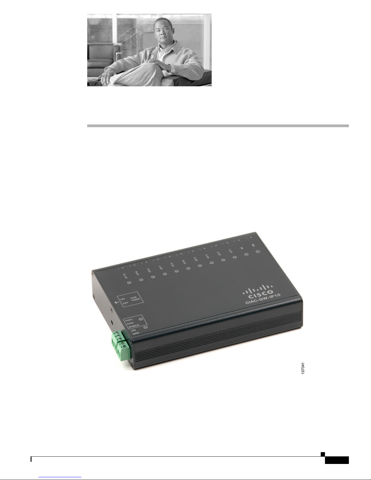
The optional Cisco Input Module (Figure 4-1) is attached to a Cisco Physical Access Gateway or Cisco
Reader Module to provide additional connections for up to ten input devices. Each connection can be
configured as supervised or unsupervised. A supervised connection is a four- state connection to
determine if the connection is (1) short (2) is open (3)normal state or (4) alarm state. An unsupervised
input indicates only normal or alarm.
Figure 4-1 Cisco Input Module
OL-20932-01
Cisco Physical Access Gateway User Guide
4-1
Page 2
Package Contents
271597
Chapter 4 Connecting a Cisco Input Module
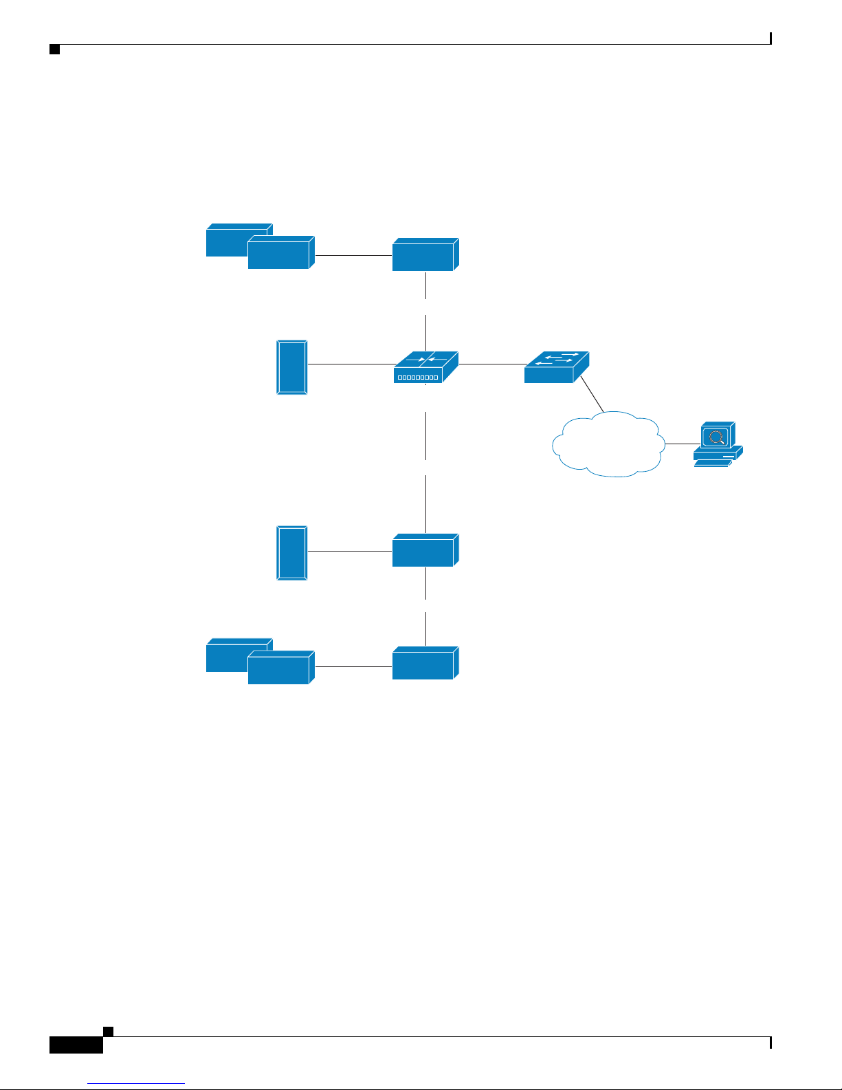
The optional Cisco Input Module is connected to a Cisco Physical Access Gateway or Cisco Reader
Module using a CAN connection to provide connections for additional input devices, as, as shown in
Figure 4-2.
Figure 4-2 Cisco Reader Module connected to the Cisco Physical Access Gateway
Cisco Input or Output
Module (Optional)
Additional
Input/Output devices
CAN connection
Access Layer
Door Readers
and Input/Output
devices
Ethernet
Cisco
Access Gateway
CAN connection
switch
Cisco
IP Network
Cisco Access
Control Manager
Door Readers
and Input/Output
devices
Additional
Input/Output devices
Package Contents
Each Cisco Input Module includes the following:
• 20 resistors (1K) for input supervision
• 2 mounting brackets, with 4 screws for each bracket
• Regulatory compliance and safety information
• Quick start guide
Cisco Reader
Module (Optional)
CAN connection
Cisco Input or Output
Module (Optional)
Cisco Physical Access Gateway User Guide
4-2
OL-20932-01
Page 3
Chapter 4 Connecting a Cisco Input Module
• Connector plugs:
Type Quantity
3 Pin 1
2 Pin 13
Physical Overview and Port Description
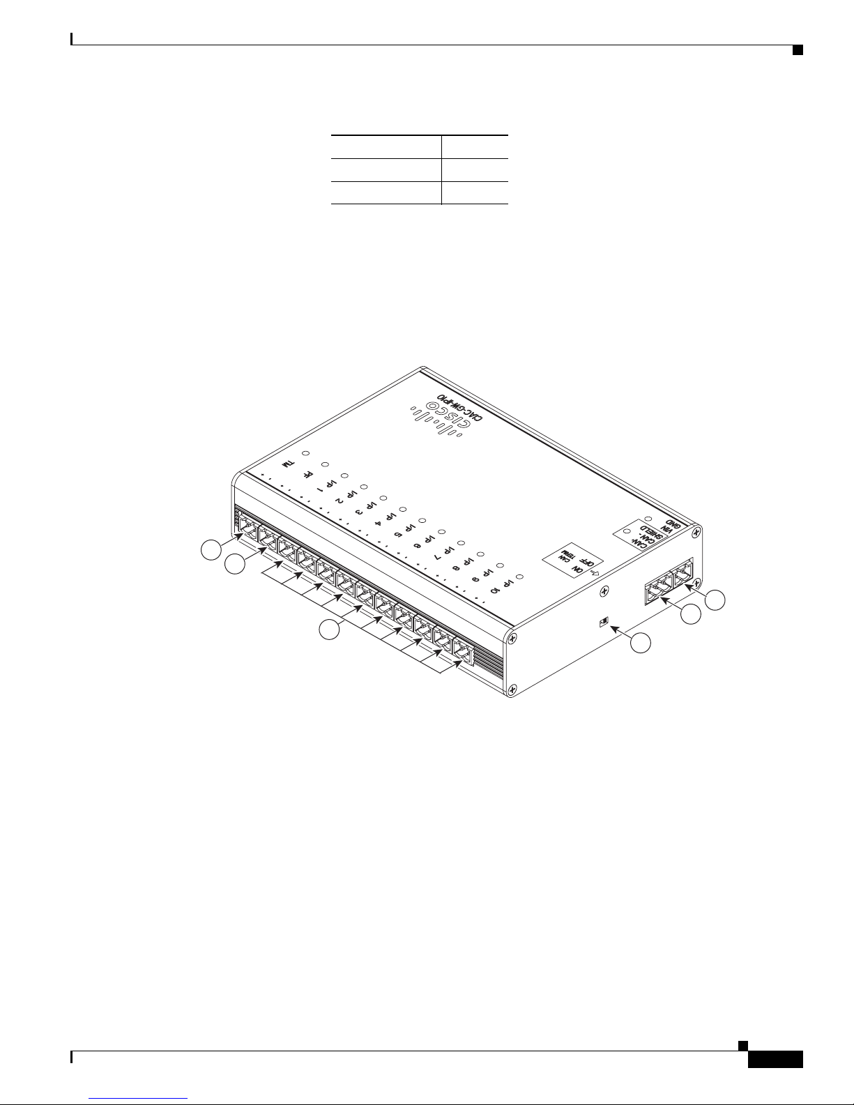
Each Cisco Input Module includes 10 ports for connecting additional input devices. as shown in
Figure 4-3.
Figure 4-3 Cisco Input Module Ports and Connectors
Physical Overview and Port Description
6
5
1
2
4
3
187043
OL-20932-01
Cisco Physical Access Gateway User Guide
4-3
Page 4

Physical Overview and Port Description
Figure 4-4 Cisco Input Module Ports and Connectors: Top View
Chapter 4 Connecting a Cisco Input Module
4
5 6
3
2
1
187039
The following items are shown in Figure 4-3 and Figure 4-4:
Type Description
1 Power Two-pin connector for Voltage In (VIN) and Ground (GND) to
connect a 12 to 24 VDC external power source.
2 CAN interface A 3-wire CAN bus is used to connect additional modules.
Note Modules are connected using the CAN1 interface. The
CAN2 interface is not supported in this release.
3 CAN Terminator The CAN terminator switch is set to ON for the last device in a CAN
wiring bus. This switch is set to set to OFF for all other devices in
the CAN bus.
4 Input connections Ten input interfaces used to sense the contact closure. Each input
can be configured as supervised or unsupervised and can be
configured to sense a Normally Open (NO) or Normally Closed
(NC) contact.
Cisco Physical Access Gateway User Guide
4-4
• An unsupervised input senses a simple contact closure state,
including Normal or Alarm. When connected to open contacts,
the terminal voltage range is 4V to 5V. For closed contacts, the
voltage range is 0V to 0.7V.
• A supervised input senses four contact states, including
Normal, Alarm, Open and Short. These inputs require 1K
End-Of-Line (EOL) termination resistors installed at the
contacts (two resistors are included in the accessory kits for
each Input port).
OL-20932-01
Page 5

Chapter 4 Connecting a Cisco Input Module
8 PF Power fail input: an unsupervised input that raises a “power fail”
9 TM Tamper input: an unsupervised input that raises a “tamper” alarm
Status LEDs
Each input port includes a status LED that indicates the following information:
Table 4-1 Input Module LEDs
Status Description
OFF Input is not configured
GREEN Input is configured and in normal state
BLINKING GREEN Input is configured, and is receiving and alarm or other data.
BLINKING RED Input is configured, short
RED Input is configured, open
Installing the Cisco Input Module
Type Description
alarm when the circuit is open. Can be configured as an additional
unsupervised port. The corresponding LED is red when circuit is
open (when no input is connected).
when the circuit is open. Can be configured as an additional
unsupervised port. The corresponding LED is red when circuit is
open (when no input is connected).
Installing the Cisco Input Module
Install a Cisco Input Module is provide additional input connections for a Cisco Reader Module or
Gateway
Before You Begin
Verify the following:
• Verify that the module has access to a power source. See Power Options and Requirements,
page 1-10 for more information.
• Verify that you have the necessary mounting brackets or other hardware. See Mounting a Gateway
or Optional Module, page 1-12.
Installation Procedure
To install the module, perform the following procedure:
Step 1 Mount the module to a wall. See Mounting a Gateway or Optional Module, page 1-12 for more
information.
OL-20932-01
Cisco Physical Access Gateway User Guide
4-5
Page 6

Installing the Cisco Input Module
Step 2 Connect the module to the DC power source:
a. Insert a two-pin connector plug into the DC power port (Figure 4-5)
b. Connect the Voltage In (VIN) and ground (GND) wires.
See Power Options and Requirements, page 1-10 for more information.
Figure 4-5 Power Connections for the Input and Output Modules
Chapter 4 Connecting a Cisco Input Module
271599
1
2
The following items are shown in Figure 4-5:
Configuration Description
1 DC power
Connects the DC ground wire to the module.
GND (ground)
2 DC power
Connects the DC Voltage In (VIN) wire to the module.
Voltage In (VIN)
Step 3 Connect the module to the CAN bus:
a. Insert a three-pin connector plug into the CAN1 port, as shown in Figure 4-6.
b. Connect the CAN wires to the CAN bus, as shown in Figure 4-7
c. Turn the CAN terminator ON if the device is the last device in a CAN wiring bus.
Note The CAN terminator switch in included on the Reader, Input and Output modules only (the Gateway is
always the first device in the CAN bus). Set the terminator switch to OFF for all other modules in the
CAN bus.
Note The CAN2 interface is not supported in this release.
See Optional Expansion Modules, page 1-6 for more information.
Cisco Physical Access Gateway User Guide
4-6
OL-20932-01
Page 7

Chapter 4 Connecting a Cisco Input Module
Figure 4-6 CAN Connections: Input and Output Modules
Installing the Cisco Input Module
271598
1
2
3
4
The following items are shown in Figure 4-6:
Configuration Description
1 CAN+ Connects to the positive terminal of the CAN bus.
2 CAN- Connects to the negative terminal of the CAN bus.
3 Shield Connects to GND and/or Shield.
3 CAN Terminator Turn the terminator ON if the device is the last device in a CAN wiring
bus.
Figure 4-7 CAN Bus Wiring
CAN+
Sheild
CAN-
Gateway Module Reader Module Input Module Output Module
271589
Step 4
Connect input devices to the module:
a. Insert two-pin connector plugs into the input ports.
b. (Optional, for supervised input connections only). Install two End-Of-Line (EOL) 1K termination
resistors in each supervised input interface (one terminator in each connector). Figure 4-8 shows the
terminator installation for a Normally Closed (NC) and Normally Open (NO) input connection.
OL-20932-01
Cisco Physical Access Gateway User Guide
4-7
Page 8

Installing the Cisco Input Module
Figure 4-8 Input Connections: Cisco Physical Access Gateway and Reader Module
Chapter 4 Connecting a Cisco Input Module
1K,, 1%
1K,, 1%
NC
1K,, 1%
1K,, 1%
c.
Connect the wires from the input devices.
NO
187838
Note Each of the input connections can be configured as supervised or unsupervised. The tamper
(TM) and power fail (PF) inputs can be configured as additional unsupervised ports. A
supervised input supports four states: normal, alarm, open and short. An unsupervised input
indicates only normal or alarm.
Step 5 See the Cisco Physical Access Manager User Guide for information to configure the module ports.
Cisco Physical Access Gateway User Guide
4-8
OL-20932-01
 Loading...