

Page 1
4119-7704-02
CF 911 P
Operator’s Manual
Page 2

Using the Printer Properly
To ensure the optimum performance of the printer, follow the precautions listed below.
• Never place a heavy object on the printer.
• Never subject the printer to shocks.
• Never open any doors or turn the printer off while the printer is making printings.
• Never bring any magnetized object near the printer.
• Never use flammable sprays, liquids or gases near the printer.
• Never modify the printer, as a fire or electrical shock could result.
• Never remove any panel or cover which is secured. The printer contains high
voltage components which can cause electrical shock.
• Never tamper with the laser mechanism on laser-equipped models, as blindness or
other injury may result.
• Never drop paper clips, staples or other small pieces of metal through the vents or
other openings in the printer, as a fire or electrical shock can result.
• Never place containers of liquid on the printer. If liquids get inside the printer, they
can cause fire or electrical shock. If a piece of metal or any liquid gets inside the
printer, immediately turn the printer off, unplug the power cord and call your
technical representative. A fire or electrical shock can result if the printer remains
plugged in or is operated after metal or liquid gets inside.
• Never leave the printer running if it becomes unusually hot, or if smoke or an
unusual odor or noise is detected. Should any of these conditions occur,
immediately turn the printer off, unplug the power cord and call your technical
representative. A fire or electrical shock can result if the printer remains plugged in
under any of these conditions.
• Always insert the power plug all the way into the outlet.
• Always make sure that the outlet is visible, clear of the printer or printer cabinet.
• Always provide good ventilation when making a large number of continuous
printings.
• Never pull on the power cord, and always hold the plug when unplugging the power
cord. A damaged cord could result in a fire or cause an electrical shock.
• Never unplug the power cord with a wet hand, as it could cause an electrical shock.
• Always unplug the power cord before moving the printer. Moving the printer with
the power cord plugged in can damage the cord resulting in a fire or causing an
electrical shock.
• Always unplug the power cord when the printer is not going to be used for a long
time.
• Never place a heavy object on the power cord, or pull or bend it, as a fire or
electrical shock can result.
• Always ensure that the printer does not sit on or move onto the power cord or
communications cable of other electrical equipment, as malfunctioning equipment
or a fire could result.
• Always ensure that the power cord or communications cable of other electrical
equipment does not become wedged into the printer mechanism, as malfunctioning
equipment or a fire could result.
i
Page 3

ii
Using the Printer Properly
• Always use the correct power voltage, as improper voltage can cause a fire or
electrical shock.
• Never use a multiple outlet adapter, as a fire or electrical shock can result.
• Should the power cord become damaged, immediately turn the printer off, unplug
the power cord and call your technical representative. A damaged cord can result in
a fire or cause an electric shock.
• If an extension cord is needed, use one with a greater rated capacity than the
maximum power requirements of the printer. The use of an extension cord that falls
short of supporting the maximum power requirements can result in overheating or a
fire.
• Always unplug the printer whenever anything unusual is observed during operation.
Make sure that the outlet is nearby and clear of the printer and furniture.
NOTE
= Locate the Printer in a Well Ventilated Room =
A negligible amount of ozone is generated during normal operation of this unit. An unpleasant odor
may, however, be created in poorly ventilated rooms during extensive unit operation. For a comfortable,
healthy, and safe operating environment, it is recommended that the room be well ventilated.
REMARQUE
= Placer le l’appareil dans une pièce largement ventilée =
Une quantité d’ozone négligeable est dégagée pendant le fonctionnement de l’appareil quand celui-ci
est utilisé normalement. Cependant, une odeur désagréable peut être ressentie dans les pièces dont
l’aération est insuffisante et lorsque une utilisation prolongée de l’appareil est effectuée. Pour avoir la
certitude de travailler dans un environnement réunissant des conditions de confort, santé et de
sécurité, il est préférable de bien aérer la pièce ou se trouve le l’appareil.
Page 4

iii
Safety Information
SAFETY INFORMATION
This color printer is a digital printer which operates by means of a laser. There is no possibility of danger
from the laser, provided the printer is operated according to the instructions in this manual.
Since radiation emitted by the laser is completely confined within protective housing, the laser beam
cannot escape from the machine during any phase of user operation.
This machine is certified as a Class 1 laser product. This means the printer does not product hazardous
laser radiation.
LUOKAN 1 LASERLAITE
KLASS 1 LASER APPARAT
CAUTION
The use of controls, adjustments or performance of procedures other than those specified in this manual
may result in hazardous radiation exposure. Because of this, we strongly recommend that you operate
your printer only as described in this documentation.
For United States Users:
This printer is certified as a Class 1 Laser product under Radiation Performance Standard according to the
Food, Drug and Cosmetic Act of 1990. Compliance is mandatory for Laser products marketed in the
United States and is reported to the Center for Devices and Radiogical Health (CDRH) of the U.S. Food
and Drug Administration of the U.S. Department of Health and Human Services (DHHS). This means
that the FAX does not produce hazardous laser radiation.
The label shown below indicates compliance with the CDRH regulations and must be attached to laser
products marketed in the United States.
WARN I NG
Use of controls, adjustments or performance of procedures other than those specified in this manual
may result in hazardous radiation exposure.
[Internal Laser Radiation]
Maximum Radiation Power: 26.79µW
Wave Length: 780nm
Page 5

iv
Safety Information
For European Users:
WARN I NG
Use of controls, adjustments or performance of procedures other than those specified in this manual
may result in hazardous radiation exposure.
This is a semiconductor laser. The maximum power of the laser diode is 26.79µW and the wavelength is
780nm.
For Denmark Users:
ADVARSEL
Usynlig laserstråling ved åbning, når sikkerhedsafbrydere er ude af funktion.
Undgå udsættelse for stråling.
Klasse 1 laser produkt der opfylder IEC825 sikkerheds kravene.
For Finland, Sweden Users:
VARO I T U S
Laitteen Käyttäminen muulla kuin tässä käyttöohjeessa mainitulla tavalla saattaa altistaa käyttäjän
turvallisuusluokan 1 ylittävälle näkymättömälle lasersäteiylle.
VAR NI NG
Om apparaten används på annat sätt än i denna bruksanvisning specificerats, kan användaren utsättas
för osynlig laserstrålning, som överskrider gränsen för laser klass 1.
For Norway Users:
ADVERSEL
Dersom apparatet brukes på annen måte enn spesifisert i denne bruksanvisning, kan brukeren utsettes
for unsynlig laserstråling som overskrider grensen for laser klasse 1.
Dette en halvleder laser. Maksimal effeckt till laserdiode er 26.79µW og bφlgelengde er 780nm.
Page 6
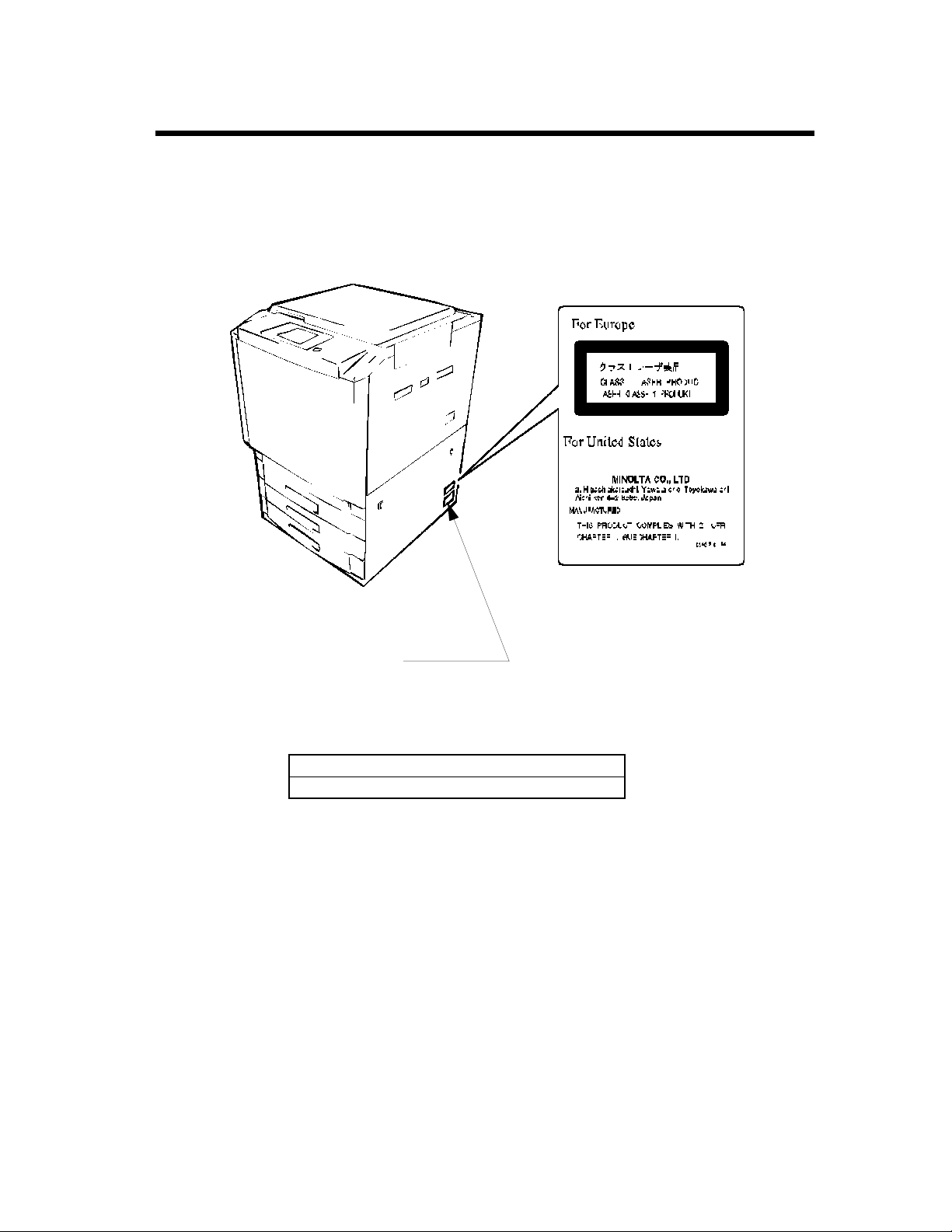
Laser Safety Labels
[Label on printer surface]
A laser safety label is attached to the outside of the printer as shown below.
v
Safety Information
Manufacturer’s Name Plate
The Manufacturer’s Name Plate is affixed at the position illustrated above.
Please write down the Model Name and Serial No. of your printer here, if necessary.
Model:
Serial No.:
C4119O009AA
Page 7

vi
Regulatry Information
WA R N I N G
This equipment has been tested and found to comply with the limits for a Class A digital device, pursuant
to Part 15 of the FCC Rules. These limits are designed to provide reasonable protection against harmful
interference when the equipment is operated in a commercial environment. This equipment generates,
uses, and can radiate radio frequency energy and if not installed and used in accordance with the
instruction manual, may cause harmful interference to radio communications. Operation of this
equipment in a residential area is likely to cause harmful interference in which case the user will be
required to correct the interference at his own expense.
The design and production of this unit conforms to FCC Regulations, and any changes or modifications
must be registered with the FCC and are subject to FCC control. Any changes made by the purchaser or
user without first contacting the manufacturer will be subject to penalty under FCC regulations.
FCC-F01
This Class A digital apparatus complies with Canadian ICES-003.
Cet appareil numérique de la classe A est conforme à la norme NMB-003 du Canada.
IC-F03
Page 8

vii
Regulatry Information
Thank you for choosing Minolta.
This operator’s manual explains how to operate the color printer and replenish its supplies. It also gives
some troubleshooting tips as well as general precautions to be observed when operating the color printer.
To ensure the best performance and effective use of your color printer, read this manual carefully until
you familiarize yourself thoroughly with its operation and features. After you have read through the
manual, keep it for ready reference.
Please use this manual as a quick and handy reference tool for immediately clarifying any questions
which may arise.
CE Marking (Declaration of Conformity)
We declare under our sole responsibility that the color printer and options to which this declaration relates
is in conformity with the specifications below.
This declaration is valid for the area of the European Union (EU) only.
Product Type Digital Full Color Printing Machine
Product Name CF911P
Options ST-103, S-105, C-101, AD-7, DT-104
Standards
EC Directives Safety : 73 / 23 / EEC and 93 / 68 / EEC
*2
Safety
: EN 60 950 / 1992 (A1:1993, A2:1993, A3:1995, A4:1997)
(Safety of information technology equipment, including electrical
business equipment)
EN 60825 / 1992 (A11:1996)
(Radiation safety of laser products, equipment classification,
requirements and user’s guide)
*1
EMC
: EN 55 022 (Class B) / 1994 (A2 : 1997)
(Limits and method for measurement of radio disturbance characteristics
of information technology equipment (ITE))
EN 50 082-1 / 1992
(Electromagnetic compatibility - Generic immunity standard
Part 1: Residential, commercial and light industry)
IEC 801-2 / 1991 (Electrostatic discharge requirement)
IEC 801-3 / 1984 (Radiated electromagnetic field requirement)
IEC 801-4 / 1988 (Electrical fast transient / burst requirement)
Note : *1) EMC performance: This product was designed for operation in a
typical office environment.
*2) First year of labeling according to EC-directive 73/23/EEC and 93/
68/EEC: 98
EMC : 89 / 336 / EEC and 93 / 68 / EEC
Page 9

viii
Technical Support
Thank you for choosing Minolta quality. For over 30 years Minolta has been a leader on the forefront of
office equipment technology and service. Our desire has always been to bring you highly reliable
products. We pledge to continue to provide you, our customer, with our state of the art equipment, as well
as full customer service for all our products. We look forward to a long healthy relationship with you and
our company. If you have any questions or comments about Minolta, our product or service, please let us
know. Our fax number is 800-237-8087 (for U.S.A. and Canada). Thank you again.
This operator’s manual explains how to operate the color printer and replenish its supplies. It also gives
some troubleshooting tips as well as general precautions to be observed when operating the color printer.
To ensure the best performance and effective use of your color printer, read this manual carefully until
you familiarize yourself thoroughly with the it’s operation and features. After you have read through the
manual, keep it ready for reference.
Please use this manual as a quick and handy reference tool for immediately clarifying any questions
which may arise.
MC-F01
Page 10
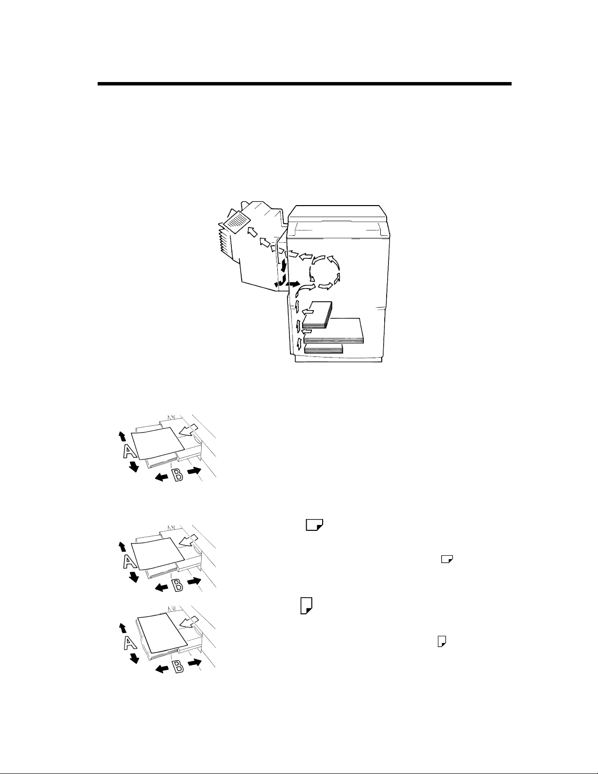
Terms and Symbols for the Type of Printer Paper
A few special terms and symbols are used in this manual to designate the types of printer paper.
Feeding Direction (printer paper path)
In this system, printer paper is taken up from the left-hand side of the unit and fed through the unit toward
the right-hand side, face-down onto the Exit Tray. In the figure below, the direction in which the printer
paper is fed, as indicated by the arrow, is called the “feeding direction”.
ix
“Width” and “Length”
1139O1610A
Terms and Symbols
1139O1610A
C4119O002AA
When the size of the print is described, side A is referred to as the
“width” and side B as the “length”.
A: Width
B: Length
<Lengthwise >
When the original or print has a “length” longer than its “width,”
we call it “lengthwise” and use symbol “L” or “ .”
<Crosswise >
When the original or print has a “length” shorter than its “width,”
we call it “crosswise” and use symbol “C” or “ .”
1139O1620A
Page 11

x
Contents
Contents
Organization
Chapters 1 through 3 contain the basic information for making prints.
Be sure to read these chapters before attempting to use your printer.
Using the Printer Properly ................................................................................ i
Safety Information .......................................................................................... iii
Regulatory Information..................................................................................... vi
Technical Support ......................................................................................... viii
Terms and Symbols for the Type of Printer Paper...........................................ix
Chapter 1 Safety Notes .......................................................................................... 1-1
1. Installing the Printer ..................................................................................... 1-2
Installation Site ............................................................................................. 1-2
Power Source ................................................................................................ 1-2
Space Requirements...................................................................................... 1-2
2. Precautions for Use ...................................................................................... 1-3
Operating Environment................................................................................. 1-3
Using the Unit Properly ................................................................................ 1-3
Moving .......................................................................................................... 1-3
Care of Printer Supplies................................................................................ 1-3
Storage of Prints............................................................................................ 1-4
Chapter 2 Getting to Know Your Printer............................................................... 2-1
1. System Overview ......................................................................................... 2-2
System Overview .......................................................................................... 2-2
2. Printer Parts and Accessories ....................................................................... 2-3
3. Operation Panel ............................................................................................ 2-6
Operation Panel Names and Functions ......................................................... 2-6
4. Computer Connection .................................................................................. 2-7
5. Turning ON and OFF .................................................................................. 2-8
Turning ON and OFF.................................................................................... 2-8
When the unit is turned ON .......................................................................... 2-8
Continuous Printing Precautions................................................................... 2-9
Chapter 3 Printing Procedures.............................................................................. 3-1
1. Printing ......................................................................................................... 3-2
Printing Preparations..................................................................................... 3-2
Performing Printing....................................................................................... 3-2
2. Function Settings .......................................................................................... 3-3
Application Specification.............................................................................. 3-3
Printer Driver Specification .......................................................................... 3-3
Page 12

xi
Contents
Chapter 4 Setup Menu Settings .............................................................................4-1
1. Setup Menu Summary ................................................................................. 4-2
Possible Setting Items in the Setup Menu.................................................... 4-2
Setup Menu Hierarchy ................................................................................. 4-3
Setup Menu Keys ......................................................................................... 4-3
2. Setup Menu Procedures ............................................................................... 4-4
Starting the Setup Menu............................................................................... 4-4
Operating the Setup Menu............................................................................ 4-5
3. Server Setup Menu ...................................................................................... 4-8
Server Setup Menu Hierarchy...................................................................... 4-8
Server Setup Menu Setting Items................................................................. 4-8
Server Setup Menu Setting Item Details...................................................... 4-8
4. Setup Menu Transition Diagram ............................................................... 4-11
Chapter 5 Function Menu Settings ........................................................................5-1
1. Function Menu Summary ............................................................................ 5-2
Function Menu Setting Items ....................................................................... 5-2
2. Function Menu Operation Procedures ......................................................... 5-3
Starting the Function Menu.......................................................................... 5-3
Function Menu Keys .................................................................................... 5-3
Function Menu Operation ............................................................................ 5-3
3. Function Menu Transition Diagram ............................................................ 5-4
Chapter 6 When a Message Appears ....................................................................6-1
Contents
1. When the Message “LOAD IN ANY TRAY” is displayed. ....................... 6-2
Paper Loading Procedures............................................................................ 6-2
2. When the Message “TONER NEAR EMPTY” or “NO TONER” Appears 6-4
Replenishing Toner ...................................................................................... 6-4
3. When the Message “NO STAPLE” Appears .............................................. 6-6
Replacing the Staple Cartridge..................................................................... 6-6
4. When “Misfeeding Occurs.” ....................................................................... 6-8
Misfeed Location ......................................................................................... 6-8
5. When the Message “The Fuser Oil Near Empty.” Appears ...................... 6-14
6. When the Message “Alert, Service code” is displayed. ............................ 6-14
7. What Does Each Message Mean? ............................................................. 6-15
What Does Each Message Mean?.............................................................. 6-15
Chapter 7 Troubleshooting ....................................................................................7-1
1. When This Type of Print is Produced ......................................................... 7-2
2. Printer Malfunctions .................................................................................... 7-3
The printer is malfunctioning....................................................................... 7-3
Chapter 8 Miscellaneous ........................................................................................8-1
1. Specifications .............................................................................................. 8-2
Specifications ............................................................................................... 8-2
2. Care of the Unit ........................................................................................... 8-6
Cleaning ....................................................................................................... 8-6
3. Paper Size Table .......................................................................................... 8-7
4. Index ............................................................................................................ 8-8
Index............................................................................................................. 8-8
Page 13

Contents
xii
Page 14

Chapter 1
1-1
Safety Notes Chapter 1
Safety Notes
Page 15
1-2
1. Installing the Printer
Installation Site
To ensure optimal safety and prevent possible malfunctions of the unit, install the printer in a location
which meets the following requirements.
◆ A place away from a curtain or the like that may
catch fire and burn easily.
◆ An area where there is no possibility of being
splashed with water or other types of liquid.
◆ An area free from direct sunlight.
◆ A place out of the direct air stream of an air
conditioner, heater, or ventilator.
◆ A well-ventilated place.
Safety Notes Chapter 1
◆ A dry place.
◆ A dust-free location.
◆ An area not subject to undue vibration.
◆ A stable and level location.
◆ A place where ammonia or other organic gas is
not generated.
◆ A place which does not put the operator in the
direct stream of exhaust from the printer.
◆ A place which is not near any kind of heating
device.
Power Source
The power source voltage requirements are as follows.
◆ Use a power source with little voltage fluctuation.
Voltage Fluctuation : Within ± 10% (for U.S.A. and Canada)
Specified voltage ± 10% (For EU)
Frequency Fluctuation : Within ± 0.3% (For U.S.A. and Canada)
Specified frequency ± 3Hz (For EU)
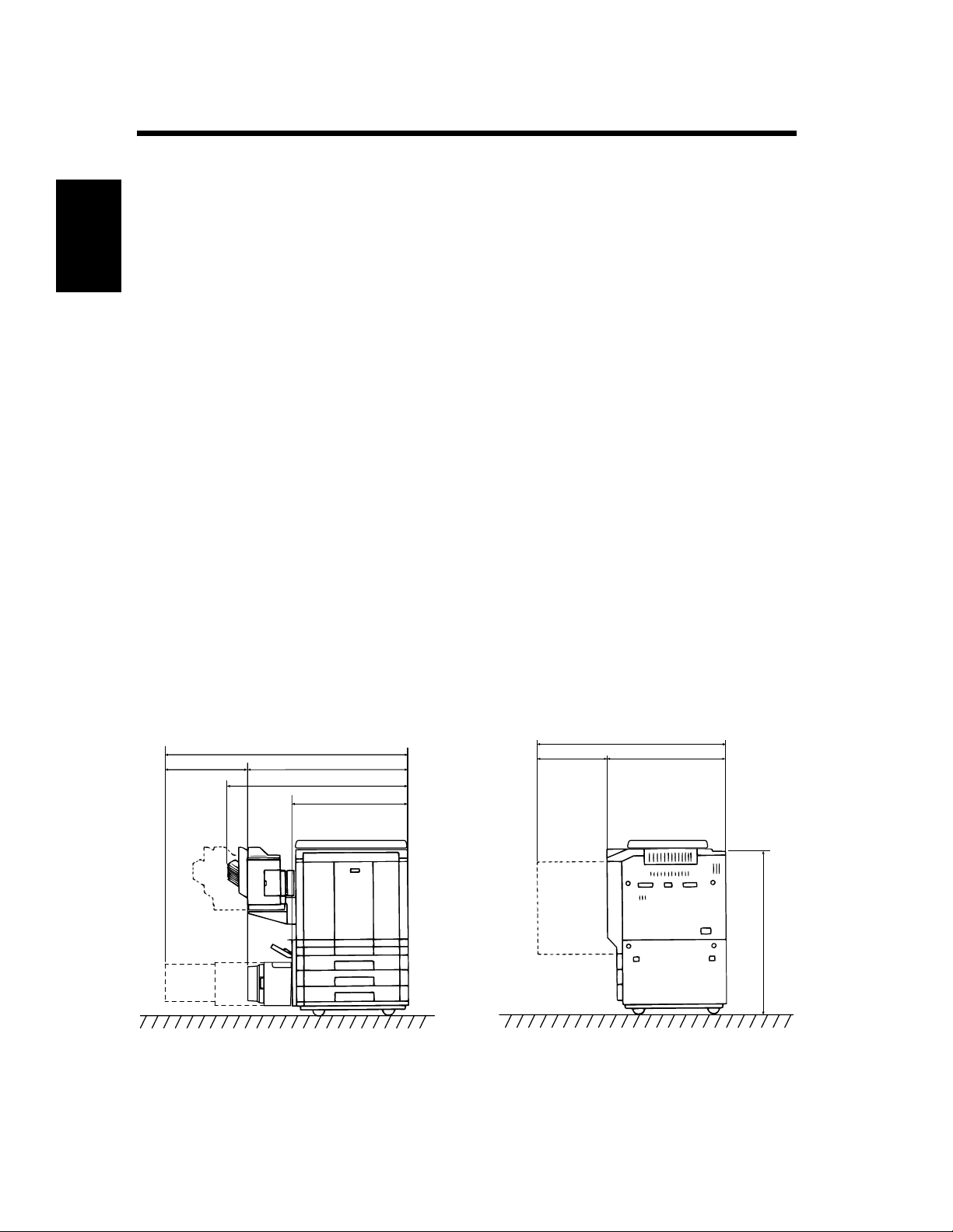
Space Requirements
To ensure easy printer operation, supply replacement and service maintenance, observe the recommended
space requirements detailed below.
* Be sure to allow a clearance of 150 mm (6") or more at the back of the printer as there is a ventilation
duct.
622 (24-1/2)
1,543 (6-3/4)
1086 (42-3/4)
921 (36-1/4)
640 (25-1/4)
1,276 (50-1/4)
511 (20) 765 (30)
1,024 (40-1/4)
Scale: mm(inch)
C4119O003AA
Page 16

2. Precautions for Use
Operating Environment
The operating environmental requirements of the printer are as follows.
Temperature : 10°C to 30°C (50°F to 86°F) with a fluctuation of 10°C (50°F) per hour.
Humidity : 25% to 85% with a fluctuation of 20% per hour.
Using the Unit Properly
To ensure the optimum performance of the unit, follow the precautions listed below.
◆ NEVER place a heavy object on the unit or subject the unit to any shock.
◆ NEVER open any Doors, or turn OFF the unit while it is printing.
◆ NEVER bring any magnetized object or use flammable sprays near the unit.
◆ NEVER modify the unit as a fire or electrical shock could result.
◆ ALWAYS insert the Power Plug all the way into the outlet.
◆ ALWAYS make sure that the outlet is visible, clear of the unit or unit cabinet.
◆ ALWAYS provide good ventilation when producing a large number of continuous prints.
NOTE
= Locate the Printer in a Well Ventilated Room =
A negligible amount of ozone is generated during normal operation of this unit. An unpleasant odor
may, however, be created in poorly ventilated rooms during extensive unit operation. For a comfortable,
healthy, and safe operating environment, it is recommended that the room be well ventilated.
1-3
Safety Notes Chapter 1
REMARQUE
= Placer le l’appareil dans une pièce largement ventilée =
Une quantité d’ozone négligeable est dégagée pendant le fonctionnement de l’appareil quand celui-ci
est utilisé normalement. Cependant, une odeur désagréable peut être ressentie dans les pièces dont
l’aération est insuffisante et lorsque une utilisation prolongée de l’appareil est effectuée. Pour avoir la
certitude de travailler dans un environnement réunissant des conditions de confort, santé et de
sécurité, il est préférable de bien aérer la pièce ou se trouve le l’appareil.
Moving
If you need to transport the unit over a long distance, consult your Technical Representative.
Care of Printer Supplies
Use the following precautions when handling the unit supplies (toner, paper, etc.).
◆ Store the paper, toner and other supplies in a location free from direct sunlight and separate from any
heating apparatus. Keep these supplies in a dry, clean environment.
◆ Store paper which has been removed from its wrapper but not loaded into the Drawer, in a sealed
plastic bag in a cool, dark place.
◆ Keep supplies out of the reach of children.
◆ If your hands become soiled with toner, wash them with soap and water immediately.
Page 17

1-4
2. Precautions for Use
Storage of Prints
• If prints are to be kept for a long time, keep them in a place which is not exposed to light to prevent fading.
• If an adhesive containing solvent (e.g., spray glue) is used to past printings, the toner on the prints can
melt.
• The color prints have a toner layer thicker than the normal black-and-white prints. When a color print is
folded, therefore, the toner can be broken at the fold.
NOTE
This unit is equipped with a counterfeit prevention function that can cause slight noise in the printed
image.
Safety Notes Chapter 1
Useful Tip
By activating the “Print Track Functions” offered by this unit, only authorized users who enter their
unique access number can use the printer. This function helps prevent dishonest use of the unit.
Page 18

Chapter 2
2-1
Getting to Know Your Printer
Getting to Know Your Printer Chapter 2
Page 19
2-2
1. System Overview
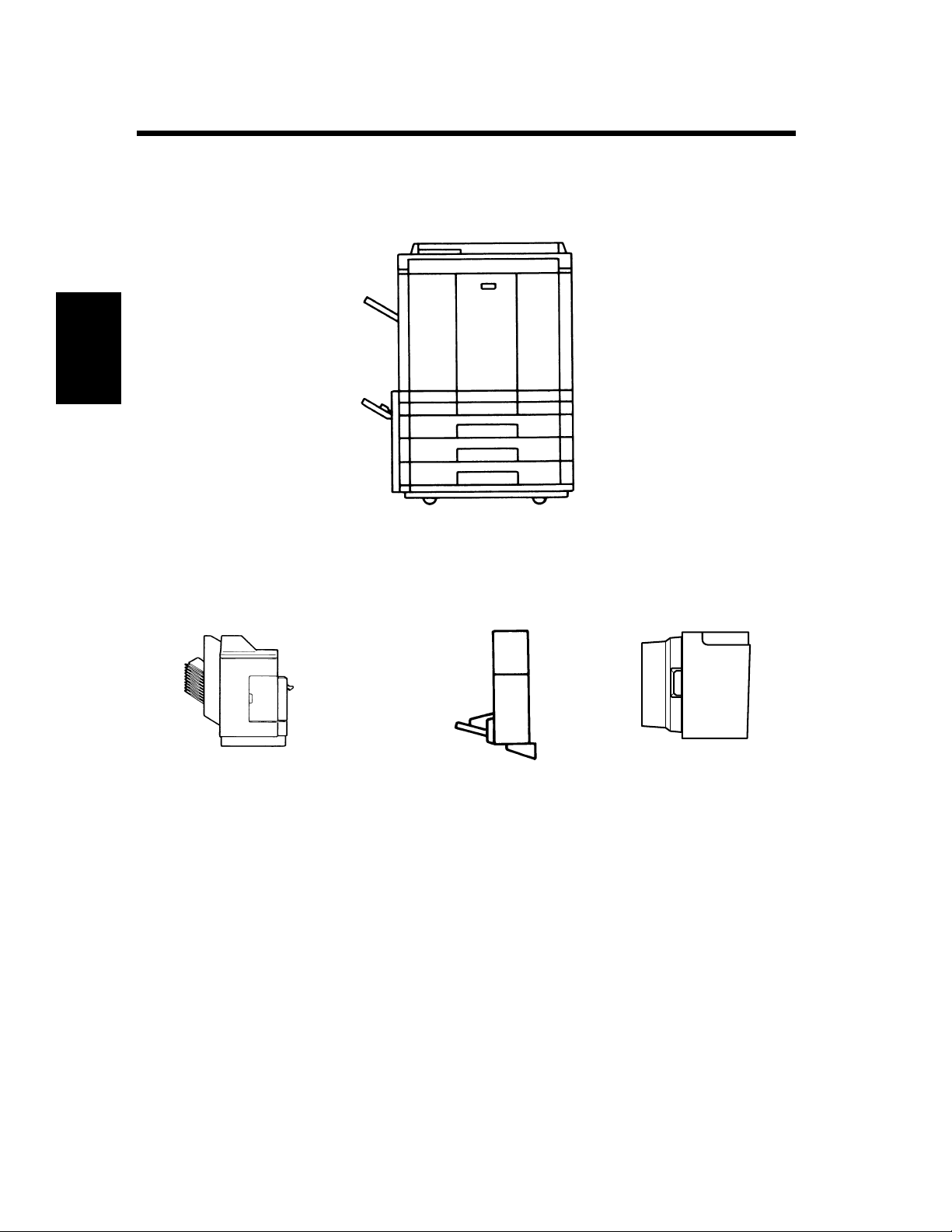
System Overview
1144O003AB
Getting to Know Your Printer Chapter 2
Sorter S-105/Staple Sorter
ST-103 <Option>
Permits automatic sorting or
grouping of prints into 10 print
sets or stacks. In addition, the
Staple Sorter automatically
staples the printed sets or stacks
that are sorted or grouped.
1139O0020A
1144O184AA
Duplex Unit
AD-7 <Option>
Automatically turns over
one-sided prints to
produce two-sided prints.
1154O028AA
Large Capacity Cassette
C-101 <Option>
Holds up to 1,000 sheets of
A4C (LetterC) print paper
(80 g/m
2
or 21-1/4 lbs).
Page 20
2. Printer Parts and Accessories
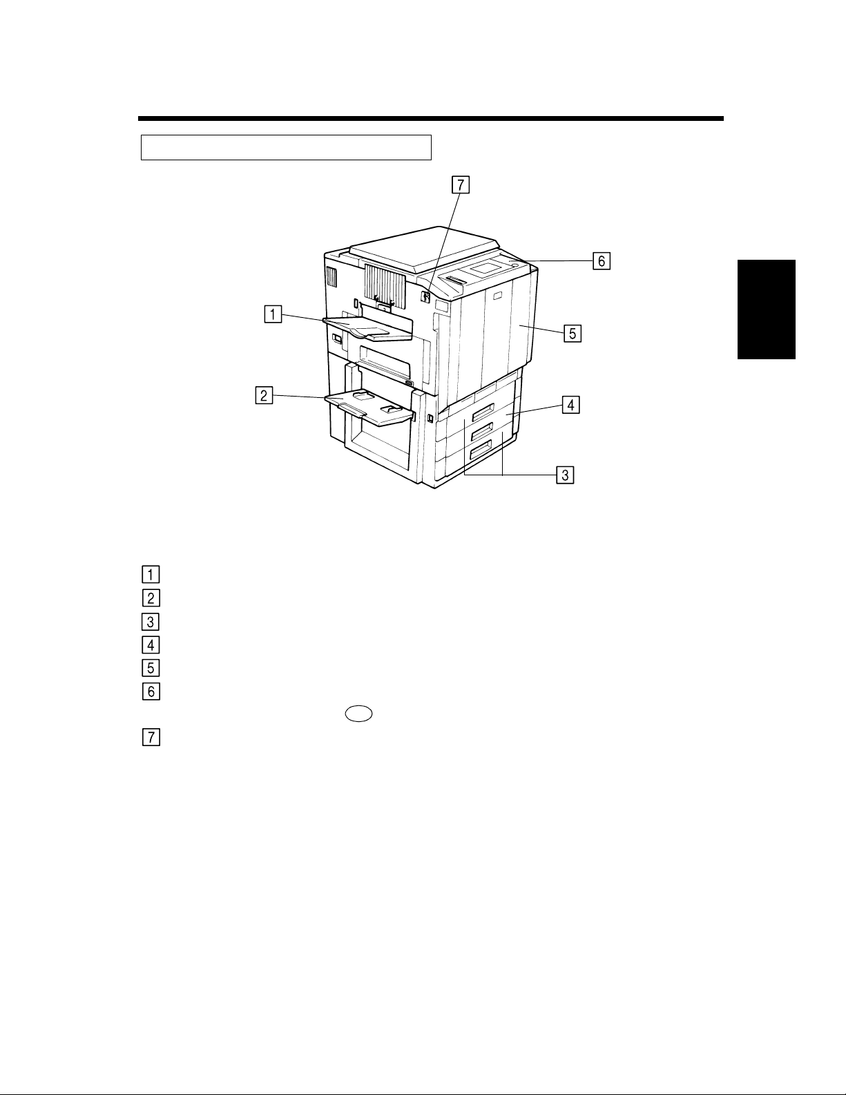
Outside the Unit
2-3
Exit Tray:
Manual Bypass Tray:
Upper/Lower Tray:
Middle Tray (Universal):
Front Door:
Operation Panel:
Power Switch:
C4119O004AA
Holds the prints ejected from the unit.
Use for manual feeding of printer paper into the unit.
Holds up to 500 sheets of paper. ☞ p. 6-2
Holds up to 250 sheets of paper. ☞ p. 6-2
Open to clear a paper misfeed or add toner. ☞ pp. 6-4, 6-9
Use to verify the printer condition and perform the menu settings.
See
Operation Panel Keys and Touch Panel. ☞ p. 2-6
Use to turn the printer ON and OFF. ☞ p. 2-8
Getting to Know Your Printer Chapter 2
Page 21
2-4
2. Printer Parts and Accessories
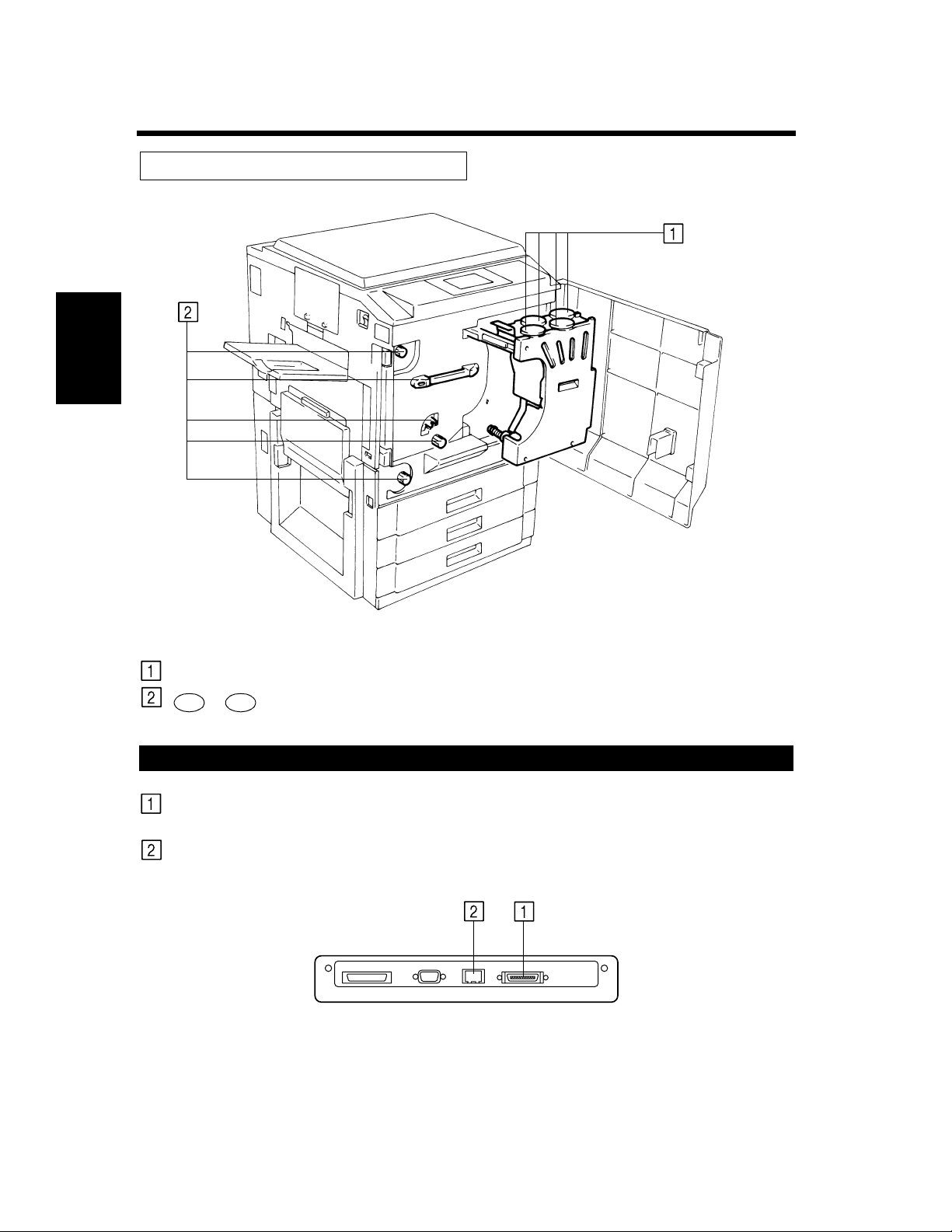
Inside the Unit
Getting to Know Your Printer Chapter 2
Toner Hopper Lid:
~ :
M1 M9
Connector Layout
IEEE1284:
Ethernet (10/100 Base-T):
C4119O005AA
Open when adding toner. ☞ p. 6-4
Operate these parts to clear misfed sheets of paper. ☞ p. 6-8
This is connected to the printer port of the computer by a parallel
interface cable.
This is connected to the computer through the network and
corresponds to 10/100 Base-T.
C4119O024AA
Page 22
Options
2-5
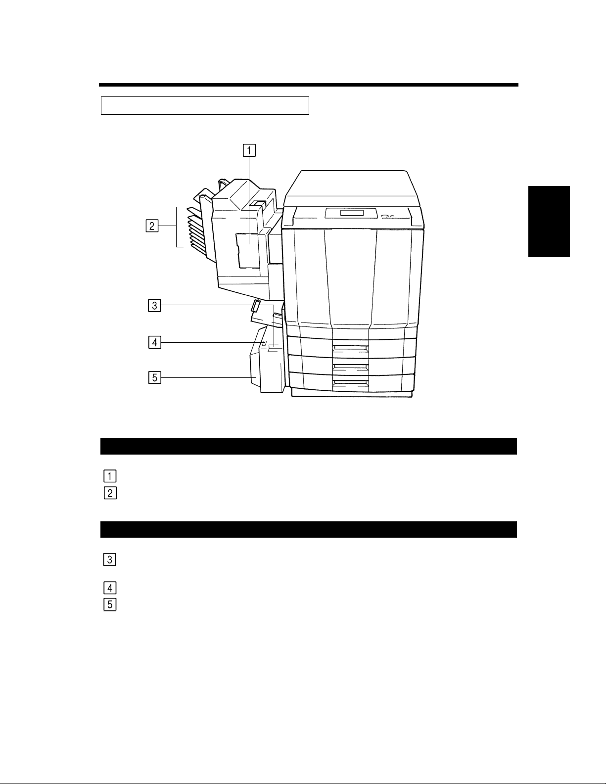
2. Printer Parts and Accessories
Sorter / Staple Sorter
Stapler Door:
Sort Bins:
Large Capacity Cassette
Cassette Release Lever:
Paper Plate Descent Key:
Cassette Door:
C4119O006AA
Open to replace the Staple Cartridge. ☞ p. 6-6
Holds sorted or grouped prints.
Use to release the cassette from the unit when it is necessary to clear
a misfeed.
Press to lower the paper plate.
Open to add paper or clear a misfed sheet of paper.
Getting to Know Your Printer Chapter 2
Page 23
2-6
3. Operation Panel
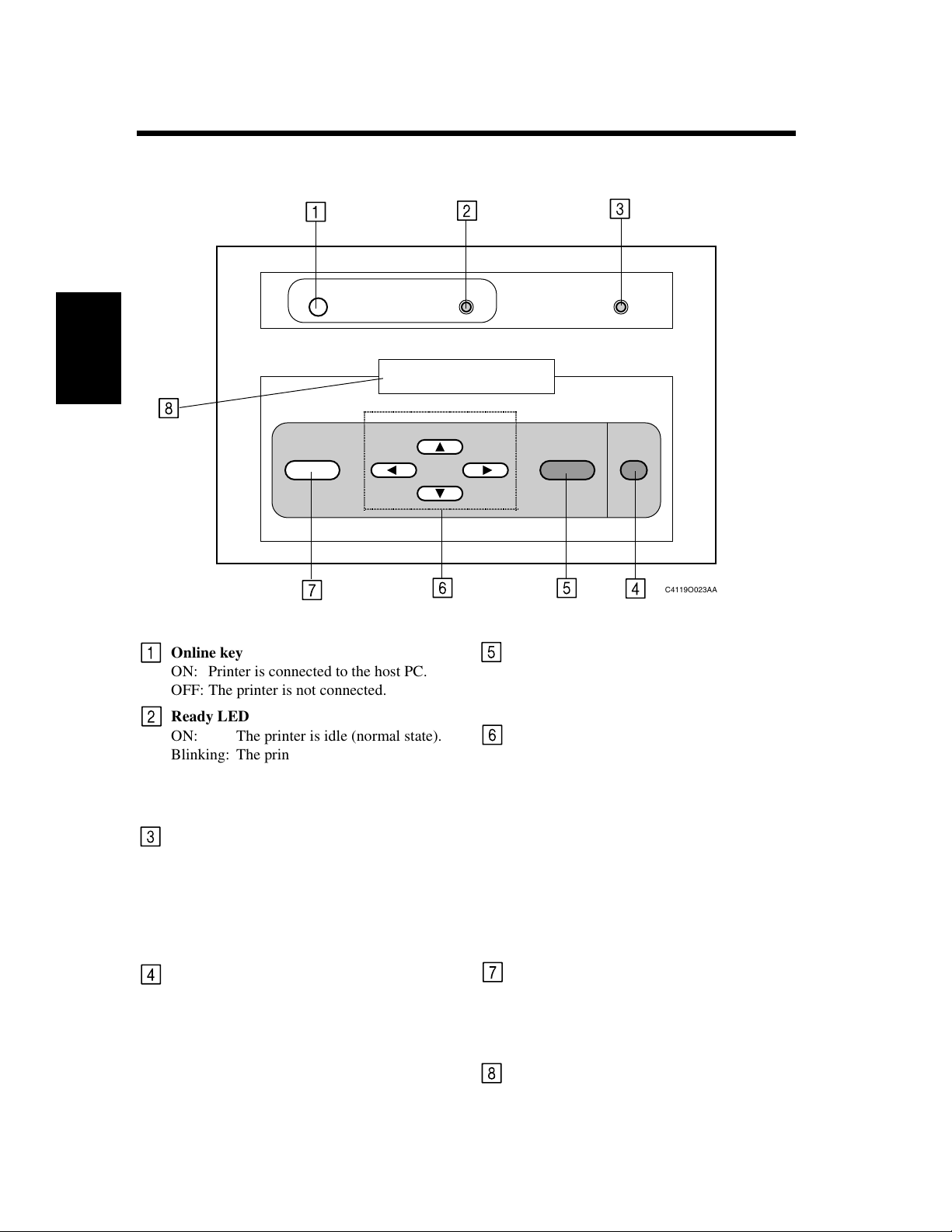
Operation Panel Names and Functions
O
1234567890123456
ABCDEFGHIJKLMNOP
C
Getting to Know Your Printer Chapter 2
Online key
ON: Printer is connected to the host PC.
OFF: The printer is not connected.
Ready LED
ON: The printer is idle (normal state).
Blinking: The printer is processing or print-
ing a job, or communicating with
a remote computer.
OFF: The printer is off or warming up.
Message LED
ON: A communication error has
occurred between the Fiery X2e
and the printer.
Blinking: An error has occurred that pre-
vents printing.
OFF: There is no error.
Cancel key
When the printer is in printer mode, switches
from the Functions screen to the Status
screens.
If pressed before paper feeding begins, cancels the current printing job.
C4119O023AA
Set key
Selects the Functions menu.
Selects the currently displayed choice and
proceeds to the next option.
▼
, , key
▲, ▼
The up arrow takes you to the next entry in
the list.
The down arrow takes you to the previous
entry in the list.
The right arrow in the setup menus advances
the cursor to the text-entry position to the
right.
The left arrow in the setup menus backspaces the cursor to the test-entry position to
the left. In a text field, it deletes the characters to the left.
Menu key
In the setup menus, takes you back one level.
When the printer is in printer mode, switches
between the Info screen and the Functions
screen.
LCD Panel
2-line text display.
▼
Page 24
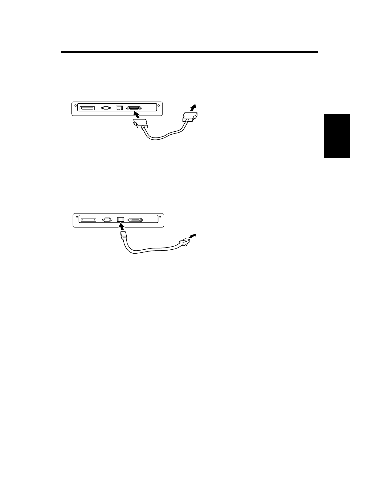
4. Computer Connection
Parallel Connection
Use a parallel interface cable when connecting this unit to the printer port of a computer.
C4119O007AA
Network Connection
Use a network cable of 10Base-T or 100Base-T when connecting this unit to a computer by a network.
2-7
C4119O008AA
Getting to Know Your Printer Chapter 2
Page 25

2-8
5. Turning ON and OFF
Turning ON and OFF
• Turning the printer ON
Press the Power Switch to the (ON) position.
• Turning the printer OFF
Press the Power Switch to the (OFF) position.
C4119O010AA
When the unit is turned ON
The operation panel changes as follows when the power is turned ON.
(1) The printer self-test operation is performed automatically.
START SELF_TEST
(2) It then enters the setup stand-by mode. Press any key (i.e. the menu key) when in this mode to switch
to the setup mode. (☞ p. 4-4) It will enter the printing mode if no operations are made.
To update/setup
Getting to Know Your Printer Chapter 2
(3) The printer system is prepared if no operation is performed in the condition given above.
(4) The printer then enters the printing ready mode. The Ready lamp will be illuminated.
However, the printing operation cannot be performed even if data from the computer is sent at this time.
A warm-up time of approximately nine minutes (at a room temperature of 20ºC (68ºF)) is required before
printing can be performed. Data can be received and printing will commence in the order of receipt once
warm-up is completed.
NOTES
• If the fusing temperature drops excessively during a multi-print cycle, there is a possibility that the
printing speed will be reduced. The printing speed will automatically return to normal when the fusing
temperature rises enough to ensure good fusing performance.
• When the power is switched ON but the CF911P does not display “Ready,” switch the power Off and
On again.
Press any key
LOADING SYSTEM
READY
name
Printer name
READY
2100MB P1.0
Disk size
Ve r s i o n
Page 26

5. Turning ON and OFF
Continuous Printing Precautions
The printing operation stops for the following intervals and the transfer drum cleaning operation is
performed for approximately 40 seconds to maintain optimal performance of the color printer. Wait a
moment when this condition occurs.
Full-color or monochrome printing:..............Every 24 prints for continuous printing and 48 prints for
non-continuous printing.*
Black-and-white mode: ................................. Every 56 prints for continuous printing and 48 prints for
non-continuous printing.*
* These figures vary according to the selected print size and other setting conditions.
2-9
Getting to Know Your Printer Chapter 2
Page 27

2-10
Getting to Know Your Printer Chapter 2
Page 28

Chapter 3
3-1
Printing Procedures
Printing Procedures Chapter 3
Page 29

3-2
1. Printing
Printing Preparations
The printer driver for this unit must be installed in advance in the computer to perform the printing
operations. Refer to the separate Getting Started manual for a description of the printer driver installation
procedures.
Performing Printing
The software application which creates the document performs the printing. Various functions can be set
by the print driver at this time. Refer to the separate User Guide.
Printing Procedures Chapter 3
Page 30

3-3
2. Function Settings
Application Specification
The size and color of the document can be set by the software application of the document. Check the
functions which can be set in the operation manual of the software application.
Printer Driver Specification
Special functions of this printer such as the sort and staple operation are set by the functions of the printer
driver. The printer driver can be called from any dialog box that is opened when printing is performed.
Refer to the printer driver operation manual for a detailed description of the setting procedures and setting
items.
Printer driver screen
4119D003
Printing Procedures Chapter 3
Page 31

3-4
Printing Procedures Chapter 3
Page 32

Chapter 4
4-1
Setup Menu Settings
Setup Menu Settings Chapter 4
Page 33

4-2
1. Setup Menu Summary
Possible Setting Items in the Setup Menu
The connection port, network settings, print job management and other items in the setup menu set the
conditions when printing is performed.
The main menu contains the following selections. There are lower-position sub-menus depending on the
main menu and the various items that can be set.
Refer to the Setup Menu Transition diagram (☞ p. 4-11) for a detailed description of the possible setting
items.
Setup Main Menu Explanation
Ends the setup menu.
Setup
Exit
Sets the server conditions such as the server name, date, time
Setup
Server Setup
Setup
Network Setup
and the job processing procedures.
Sets the connection conditions such as the port that is used.
Also sets the protocol, server address and other items when
the unit is connected to a network.
Setup Menu Settings Chapter 4
Setup
Printer Setup
Setup
PS Setup
Setup
Color Setup
Setup
Job Log Setup
Setup
Calibration
Setup
Change Password
Sets the conditions for the job processing of the printer name
and queue.
Sets the Postscript functions such as the color and the compression.
Sets the conditions for color matching such as the color mode
and target.
Sets the job log storage and printing conditions.
Executes the calibration.
Changes the password.
Setup
Clear Server
Initializes the server.
Page 34

4-3
1. Setup Menu Summary
Setup Menu Hierarchy
The setup menu contains a number of levels of submenus under the main menu that were explained in the
chart on the previous page. A submenu is separated into four levels. The lowest levels are
Setup], [Protocol Setup], [IPX/SPX Setup]
[Frame Types]
and
.
Main Menu Sub Menu Setting Items
Level 1 Level 2 Level 3 Level 4
From Server Setup
▼
key
Setup
Network Setup
Network Setup
Exit
Set key
[Network
Server Setting Items
Network Setup End
Go to the Printer Setup
Network Setup
Port Setup
Network Setup
Protocol Setup
Go to the Service Setup
Port Setup
Exit
To Ethernet Setup,
Parallel Setup
Protocol Setup
Exit
To AppleTalk Setup
TCP/IP Setup
Protocol Setup
IPX/SPX Setup
IPX/SPX Setup
Exit
IPX/SPX Setup
Frame Types
Go to the Clear Frames
Frame Setup
Exit
Frame Setup
Ethernet ?
Por t Set up End
Setting Items
Protocol Setup End
Setting Items
IPX/SPX Setup End
Frame Setup End
Setup Menu Settings Chapter 4
Frame Type
Setting Items
Setting Items
Setup Menu Keys
The following keys are used to switch between the levels and menus.
▲, ▼ keys: These keys switch between the menus, items and setting values that are displayed. The oper-
ation corresponds to the sequence indicated by the arrow marks in the figure shown above.
▼
, keys: These keys shift the cursor horizontally within the display.
▼
Set key: This key selects the menus and items that are displayed and the menu display and items in
Cancel key: This key interrupts the menu and items that are displayed and returns operation to the
These keys are also used to switch between numerical values and characters.
the lower level. The operation corresponds to the horizontal arrow marks in the figure above.
menu and items at the previous upper level.
Page 35

4-4
2. Setup Menu Procedures
Starting the Setup Menu.
The Setup menu is made available when the printer is started.
(1) Turn on the power.
(2) Press any key (i.e. the menu key) when the following message is displayed.
To update/setup
Press any key
This message is displayed for approximately 5 seconds. If no operation is performed at this time, the
printer ready mode is set. The following service option screen is displayed by pressing any key.
Startup
Run Setup
(3) To access the setup menu, press the
open the setup menu and the following screen will be displayed.
LOADING SETTINGS
If a password is set, enter the password in the following operation.
the setup menu will be displayed if no password has been set.
Useful Tips
• Select “Startup Start System” under Service Options, then press the Set key to enter the print ready
state.
• In addition, under Service options, a service menu in which the printer program can be checked and
updated can be selected. For details on the service menu, please ask the service man.
(4) When a password has been set, enter the password.
ENTER PASSWORD
Password
Setup Menu Settings Chapter 4
Use the ▲ or ▼ key to switch the display of the first character.
Use the key to shift the cursor to the second character and set the second and subsequent
characters in the same manner as the first character.
After the password is input, press the
When the password has been confirmed, the
▼
Setup
Exit
Set
key while
Set
key.
“Startup Run Setup”
“Setup Exit”
screen in the Setup menu is displayed.
is displayed. This will
[Setup Exit]
at the beginning of
Page 36

2. Setup Menu Procedures
Operating the Setup Menu
The Setup menu is accessed in the following sequence: Menu selection → Set key → Submenu
selection → Set key → Select the desired setting menu and change the setting.
Refer to the section “Setup Menu Transition Diagram” (☞ p. 4-11) for an illustration of the menu
hierarchy and the items that can be set.
(1) Use the ▼ and ▲ keys to select the main menu.
Setup
EXIT
▼
Setup
Server Setup
▼
Setup
Network Setup
(Next menu)
▲
▲
▲▼
4-5
(2) Press the
Set
key. The submenu of the selected main menu (Level 1) is displayed. There may be no
submenu depending on the main menu that is selected and the setting items may be displayed
instead (☞ p. 4-11).
This example explains the condition when
Set
Setup
Network Setup
Set
If the
key is pressed by mistake, press the
key
[Network Setup]
Network Setup
EXIT
Cancel
key to return to the previous menu.
is selected from the main menu.
(3) Use the ▼ and ▲ keys to select the submenu (Level 1)
Network Setup
EXIT
▼
Network Setup
Port Setup
▼
Network Setup
Protocol Setup
▲
▲
▲▼
(Next menu)
Setup Menu Settings Chapter 4
Page 37

4-6
2. Setup Menu Procedures
(4) Press the
Set
key. Level 2 of the selected submenu (Level 1) is displayed. There may not be a Level
2 depending on the main menu that is selected, and the setting item is displayed instead (☞ p. 4-11).
This example indicates the condition when
Set
Network Setup
Protocol Setup
key
[Protocol Setup]
Protocol Setup
EXIT
is selected in the first level.
(5) Use the ▼ and ▲ keys to select the submenu hierarchy (Level 2).
Protocol Setup
EXIT
▼
Protocol Setup
Appletalk Setup
▼
Protocol Setup
TCP/IP Setup
▲
▲
▲▼
(Next menu)
(6) Press the
Set
key. Level 3 of the selected submenu (Level 2) is displayed. There may not be a Level
3 and the setting items may be displayed instead, depending on the selected menu (☞ p. 4-11).
This example describes the condition when
Set
Protocol Setup
TCP/IP Setup
key
[TCP/IP]
(7) Use the ▼ and ▲ keys to select the submenu (Level 3).
Setup Menu Settings Chapter 4
TCP/IP Setup
EXIT
▼
TCP/IP Setup
Ethernet Setup
▼
▲
▲
(Next menu)
is selected in level 2.
TCP/IP Setup
EXIT
Page 38

4-7
2. Setup Menu Procedures
(8) Press the
Set
key. The first setting item of the selected submenu (Level 3) is displayed. The menu on
Level 4 may be displayed depending on the main menu that is selected (☞ p. 4-11).
Select the menu in the same manner.
This example describes the condition when the
Set
TCP/IP Setup
Ethernet Setup
key
[Ethernet Setup]
Enable TCP/IP
No
is selected in the level 3.
Useful Tip
[Network Setup]
The
[Protocol Setup]
[Protocol Setup]
settings are required when the printer is connected to a network. In this case, the
[TCP/IP Setup]
but set also
is set directly for this explanation. However, do not actually set only
[Service Setup]
[Port Setup]
and
simultaneously.
(9) Use the ▼ and ▲ keys to select the setting value of the item. (In this example, the setting value is
Ye s /N o . )
Enable TCP/IP
No
▼
Enable TCP/IP
Ye s
(10) Press the
Enable TCP/IP
Ye s
Set
key. The following setting item is displayed.
▲
Set
key
IP Address
127.0.0.1
(11) Use the ▼ and ▲ keys to switch the numeric characters when performing the settings. Press the
key to shift the cursor (underlined section) to switch the following numeric characters.
IP Address
127
.0.0.1
▲
IP Address
128
.0.0.1
(12) Set all the numeric characters and press the
IP Address
247.123.0.1
(13) Set this item by the same procedure as described in step (11) and press the
▼
Set
key
▼
key
IP Address
.0.1
128.0
Set
key. The following setting item is displayed.
Subnet Mask
225
.225.225.0
Set
key. This ends the
Ethernet setting and operation shifts to the TCP/IP setup end menu.
Set
Subnet Mask
247
.255.123.1
key
TCP/IP Setup
Exit
(14) Continue these procedures to set the other items in the TCP/IP Setup menu.
(15) In the Setup menu, set “Save Changes” to “Yes.” (☞ p. 4-10).
▼
Setup Menu Settings Chapter 4
Page 39

4-8
3. Server Setup Menu
Server Setup Menu Hierarchy
The information for the print server and the job processing procedures are set in the Server Setup menu.
The setting items are displayed if the main menu is selected instead of the server menu.
Main Menu Sub Menu Setting Items
Setup
Server Setup
No sub menu
Server Setup Menu Setting Items
[Server Setup]
Select
Setup
Server Setup
in the main menu. The displayed setting items are set in the following sequence.
Set
key
Server Name
F
iery X2e
Character Set
Macintosh
System Date
00/00/00
Enable Printed Q
Ye s
Main Menu
Server Setup Menu Setting Item Details
Server Setting Items
Server name → System Date
System Time → Print Start Page
Character Set → Enable Printed Q
Jobs to Save → Save Changes
System Time
13:01
Jobs to Save
10
→
Print Start Page
No
Save Changes
Ye s
→
→
This section describes the display contents and meanings for each setting item.
Setup Menu Settings Chapter 4
Server Name
Server Name
F
iery X2e
Printer server name
Function: This sets the printer name that is displayed in the panel during print standby.
Operation: Use the ▼ and ▲ keys to switch the character display. Use the key to shift the
cursor (underlined section). Repeat this operation to set the name.
After the settings are completed, press the
Date]
is displayed.
[Save Change]
will be displayed if the
Set
key and the following item
Cancel
process.
▼
[System
key is pressed midway through the
Page 40

System Date
System Date
00/00/00
Function: This sets the style of the date for the printer time (date information) to Month/Day/
Operation: Use the ▼ and ▲ keys to switch the display of the numeric characters. Use the
System Time
System Time
13:01
Function: This sets the time for the printer (time information).
Operation: Use the ▼ and ▲ keys to switch the display of the numeric characters. Use the
4-9
3. Server Setup Menu
Date
Year.
key to shift the cursor (underlined section). Repeat this operation to set the date.
After this operation is performed, press the
[System Time]
[Save Change]
.
will be displayed if the
process.
Time
key to shift the cursor (underlined section). Repeat this operation to set the current
time.
After the setting is made, press the
Start Page]
[Save Change]
.
will be displayed if the
Set
process.
Set
key to display the following item,
Cancel
key is pressed midway through the
key to display the following item,
Cancel
key is pressed midway through the
[Print
▼
▼
Print Start Page
Print Start Page
No
Function: This sets the starting print page for each job.
Operation: Use the ▼ and ▲ keys to switch the Yes/No setting. After the setting is made, press
Character Set
Character Set
Macintosh
Function: This sets the panel display font.
Operation: Use the ▼ and ▲ keys to select the display font for the Macintosh, Windows or
Set
the
key to display the next item,
[Save Change]
will be displayed if the
[Character Set]
Cancel
key is pressed midway through the
.
process.
DOS operating systems.
Macintosh: This sets the character set to the fonts used on a Macintosh.
Windows: This sets the character set to the fonts used in Windows.
DOS: This sets the character set to the fonts used in DOS.
After the setting is made, press the
Queue]
[Save Change]
.
will be displayed if the
Set
key to display the following item,
Cancel
key is pressed midway through the
process.
Setup Menu Settings Chapter 4
[Print
Page 41

4-10
3. Server Setup Menu
Enable Printed Queue
Enable Printed Q
Ye s
Function: The setting determines if the print queue is used.
Operation: Use the ▼ and ▲ keys to switch the Yes/No setting. Press the
item
[Save Change]
process.
Jobs to Save
Jobs to Save
10
[Jobs to Save]
will be displayed if the
. If “No” is set,
[Save Change]
Cancel
key is pressed midway through the
Set
key to display the next
is displayed if the
Set
key is pressed.
Function: When the print queue is used, (the previous item
[Print Queue]
number of jobs that are stored in the queue is set.
Operation: Use the ▼ and ▲ keys to switch the display of the numeric characters. Use the
key to shift the cursor (underlined section). Repeat this operation to set the number
of jobs.
After the setting is made, press the
setting is performed, press the
Change]
[Save Change]
.
will be displayed if the
Set
key to display
Set
key to display the following item,
Cancel
key is pressed midway through the
process.
Save Change
Save Changes
Ye s
Function: This setting determines whether the conditions set in the Server Setup menu are
saved or not.
Operation: Use the ▼ and ▲ keys to switch the display of the numeric characters. If “Yes” is set
Setup Menu Settings Chapter 4
and the
returns. If “No” is set and the
Set
key is pressed, the changed settings are saved and the main menu display
Set
key is pressed, the changes in the settings are not
stored and the main menu display returns.
NOTE
Any Other Menu Setup Procedures
See Chapter 2 “Performing Setup from the Control Panel” in the Administrator Guide.
is set to “Yes”) the
[Save Change]
▼
. After the
[Save
Page 42

4-11
4. Setup Menu Transition Diagram
The setup menu configuration is shown in the Menu Map. Before starting the settings, verify the position
and structure of the required setting items.
To print out the Menu Map:
Press the Menu key.
The message “Print Pages” appears, press the Set key.
Press the down key and select “Menu Map”.
Press the Set key.
The Menu Map is printed out.
Setup Menu Settings Chapter 4
Page 43

4-12
Setup Menu Settings Chapter 4
Page 44

Chapter 5
5-1
Function Menu Settings
Function Menu Settings Chapter 5
Page 45

5-2
1. Function Menu Summary
Function Menu Setting Items
A test pattern that verifies the printer conditions can be printed and printing can be suspended (temporary
stop) and resumed (start operation again) in the function menu.
The main menu contains the following selections. There are lower-position submenus depending on the
main menu and various items can be set.
Refer to the Function Menu Transition Diagram (☞ p. 5-4) for a detailed description of the possible
setting items.
Function Main Menu Explanation
Enables you to print special pages from the printer.
Function
Print Pages
This option interrupts the current print job. If it has not fin-
Function
Suspend Printing
Function
Resume Print
ished processing, the RIP will continue but the job will not
print. You can then select
will print the job and continue processing and printing jobs.
NOTE: Do not select Suspend Printing while printing duplex
or sort jobs.
Resumes printing.
Resume Printing
and the printer
This function is provided for service representatives only.
Function
Run Diagnostics
Function
Reboot Server
NOTE
See Chapter 1 “Using the Control Panel” in the User Guide.
Function Menu Settings Chapter 5
Contact your authorized service/support technician for information about running diagnostics.
Shuts down all printing activity properly and then restarts the
Fiery X2e. Access to Fiery X2e Setup options are made available at this time.
Page 46

2. Function Menu Operation Procedures
Starting the Function Menu
(1) Press the MENU key.
The function menu is accessed and the following screen is displayed.
Functions
Print Page
Function Menu Keys
The following keys are used to move the among menus.
▲ , ▼ keys: These keys switch between the menus, items and setting values that are displayed. The
operation is performed in the sequence indicated by the vertical arrow marks in the figures.
▲
, keys: These keys shift the cursor horizontally within the display.
▲
Set key: This key selects the menus and items that are displayed and the menu and items in the
Cancel key: This key interrupts the menu and items that are displayed and returns operation to the
These keys are also used to switch between the numerical values and characters.
lower level. This operation corresponds to the horizontal arrow marks in the figures.
menu and items at the previous upper level.
5-3
Function Menu Operation
The Function Menu can be operated by the same procedures as the Setup Menu. (☞ p. 4-5)
Function Menu Settings Chapter 5
Page 47

5-4
3. Function Menu Transition Diagram
The function menu configuration is shown in the following diagram. Before starting the settings, verify
the position and structure of the required setting items.
Main Menu Sub Menu Setting Items
Function
Print Pages
▼ key
Function
Suspend Print
Set key
Print Pages
Test Page
Print Pages
Configuration
Print Pages
Job Log
Print Pages
Menu Map
Print Pages
Color Charts
Print Pages
Font List
Test Print Setting Items
Go to the main menu after printing.
Go to the main menu after printing.
Go to the main menu after printing.
Go to the main menu after printing.
Go to the main menu after printing.
Go to the main menu after printing.
Suspend Print Setting Item
Discontinue Printer
Function Menu Settings Chapter 5
Function
Resume Print
Function
Run Diagnostics
Function
Reboot Server
Diagnostics
Video Diags
Resume Print Setting Item
Connect Printer
Diagnostics
Diagnostics ( → Interval (min) → Diagnostics
→
Video diags Pass)
Restart
Page 48

Chapter 6
6-1
When a Message Appears
When a Message Appears Chapter 6
Page 49

6-2
1. When the Message “LOAD IN ANY TRAY” is displayed.
Paper Size
LOAD A4
IN LOWER TRAY
Tray
Paper Loading Procedures
Upper and Lower Trays
Slide the Tray out.
1
Load the paper stack into the Tray so that its
2
front side (the side facing up when the
package was unwrapped)
slide the Tray back in.
faces down.
Then,
The message shown on the left is displayed when the
Tray currently selected for use runs out of paper. The
current print cycle is interrupted and you cannot start
a new print cycle. Load the tray with paper by
performing the following procedure:
NOTE
Only the following type of paper can be loaded in
the tray. Use of paper recommended by our
company is encouraged to maintain a standard
level of print quality and prevent paper misfeeds.
• Paper weight: 64g/m² to 105g/m² (17 lbs. to 28 lbs.)
• Size: A3 lengthwise to A5 lengthwise
×17
(11
Thick paper (Heavy Stock 2) and OHP
transparencies cannot be loaded in the tray.
lengthwise to Invoice lengthwise
"
"
)
Middle Tray
Slide the Tray out.
1
Load the paper stack into the Tray so that its
2
front side (the side facing up when the
package was unwrapped) faces down. Then,
slide the Tray back in.
NOTES
• Up to 500 sheets of paper (80g/m²) (21-1/4
lbs.) can be loaded.
• The paper should be loaded no higher than the
▼
(Max. Level Indicator).
When a Message Appears Chapter 6
1144O019AA
1144L54AA
1144O022AA
NOTES
• Up to 250 sheets of paper (80g/m²) (21-1/4
lbs.) can be loaded.
• The paper should be loaded no higher than the
▼
(Max. Level Indicator).
L
1144L044AA
Page 50

6-3
A
1
2
1. When the Message “LOAD IN ANY TRAY” is displayed.
Changing the Paper Size for the
Middle Tray (Universal Tray)
Grasp the tab of the Edge Guide and slide it
1
to the size of the paper to be loaded. Pressing
the plastic part of the Trailing Edge Stop,
slide it to the size of the paper to be loaded.
1144O023AA
NOTE
When loading A3 (11"
Move the Trailing Edge Stop all the way to the
right. Then, pinch the Lever as shown and
remove it from the Stop. Next, fit the Lever into
position as shown.
×17
") paper:
Large Capacity Cassette
Grasping the Door Lock Release Lever, open
the Cassette Door.
When adding paper to a partially loaded
Cassette, press the paper Plate Descent Key
to lower the Paper Plate before opening the
Cassette Door.
Place the paper stack onto the Paper Plate so
its front side faces up
that
Cassette Door.
*This causes the Paper Plate to rise
automatically.
and close the
1154O030AA
1154O031AA
When loading Inch size paper
Flip the Switch, located in the right rear
corner of the Tray, to “Inch”.
1138O044A
1138O606EA
1154O032AA
NOTES
• Make sure that the leading edge of the paper
stack is pressed tightly up against the Guide
Plate on the take-up side of the Cassette.
• The paper should be loaded no higher than the
▼
(Max. Level Indicator).
1145O555A
1145O555KA
• The Paper Plate may not ascend if the Cassette
Door is not closed completely. Be sure to close
the Door completely.
When a Message Appears Chapter 6
Page 51

6-4
2. When the Message “TONER NEAR EMPTY” or “NO TONER” Appears
The message shown on the left appears when toner
TONER NEAR EMPTY
YELLOW
Toner Color
NO TONER
YELLOW
will run out soon. You can still make prints, but the
image density will become lighter and lighter. It is
recommended that you replenish the toner as soon as
possible for this reason.
When toner has run out, the message shown on the
left is displayed and you can no longer start a new
print cycle. Follow the procedures described below to
replenish the toner.
Replenishing Toner
Open the Front Door.
1
(Example: Yellow Toner is empty.)
Slide out the Toner Hopper Unit.
2
When a Message Appears Chapter 6
C4119O011AA
1144L013AA
Sharply tap the new Toner Bottle against a
3
desk or other hard object four to five times.
Then turn the Toner Bottle upside down and
tap it the same way again.
10
4
Shake the Toner Bottle well.
4
1144L079AB
1144L078AB
Page 52

6-5
8
9
10
11
2. When the Message “TONER NEAR EMPTY” or “NO TONER” Appears
Remove the bottle cap and peel off the seal.
5
1144L016AA
Open the Toner Hopper Lid.
6
1144L014AA
NOTE
Make absolutely certain that the color of the
toner matches the color of the Toner Hopper Lid.
After the toner stops falling in (approx. 60
seconds), tap the Bottle a few times to ensure
that all the toner falls into the Hopper.
1144L018AA
Making sure that the toner has emptied
completely, turn the Bottle counterclockwise
and lift it out of the Receptacle. Close the
Toner Hopper Lid.
1144L019AA
Align the tab on the Bottle with the cutout
7
on the Toner Receptacle and turn the Bottle
clockwise until it stops.
1144L017AA
NOTE
Please wait for a while after the toner has fallen
in completely. If not, toner powder may be blown
up from the Toner Hopper.
Slide the Toner Hopper Unit back in and
close the Front Door.
1144L020AA
Use the same procedure to add toner for the
other three Main Hoppers.
When a Message Appears Chapter 6
Page 53

6-6
3. When the Message “NO STAPLE” Appears
The message shown on the left appears when the
NO STAPLE
Replacing the Staple Cartridge
staples are running out.
Replace the Staple Cartridge with a new one by
following the procedure given below.
While holding the Lock Release Lever, slide
1
the Staple Sorter away from the unit.
Open the Stapler Door.
2
While pushing up the Staple Cartridge
3
Release Lever, pull the Staple Cartridge out
of its port.
C4119O012AA
NOTE
Check that no portion of the staple sheet hangs
out of the Cartridge. Break off any portion of the
sheet that hangs out of the Cartridge.
1134O077AA
Insert the new Staple Cartridge until a click
5
is heard.
1139O1440A
4
When a Message Appears Chapter 6
1136O003AA
Pull the staple sheet about 3 cm out of the
new Staple Cartridge and break off that
portion.
1139O0970A
Close the Stapler Door and slide the Staple
6
Sorter back against the printer.
C4119O013AA
Page 54

6-7
3. When the Message “NO STAPLE” Appears
Place a sheet of paper into the 2nd Bin of the
7
Staple Sorter.
2nd Bin
Test Print from software application. Then,
8
the Staple Sorter test-staples the paper
several times automatically.
Setup the PDD options Application Menu
print,
click “property”,
click “Fiery Options”,
click “Finishing”,
click Stapler Mode “on”.
C4119O014AA
1136O009AA
NOTES
• Replace the Staple Cartridge only after you are
prompted to do so by the message. Removing
the Staple Cartridge before then will result in
stapling trouble.
• Immediately after the new Staple Cartridge has
been loaded, be sure to test-staple the paper
following steps 7 through 9.
• DO NOT turn the green gear near the
Cartridge inside the Staple Unit.
Remove the sheet of paper from the 2nd Bin
9
and check that it has been stapled.
* If no staples are evident, place another
sheet of paper into the 2nd Bin and repeat
steps 7, 8, and 9.
1144O489AA
When a Message Appears Chapter 6
Page 55

6-8
4. When “Misfeeding Occurs.”
If a paper misfeed occurs during a print cycle, the message shown on the left is displayed and that
particular print cycle is stopped in the middle of operation.
Clear the misfed sheet of paper according to the procedure given below.
Misfeed Location
Different procedures are used to clear a misfed sheet of paper depending on the location. First, isolate the
location, then clear the misfeed following the procedure applicable to where the misfeed occurred.
Sorter/Staple Sorter ☞ p. 6-13
Duplex Unit ☞ p. 6-13
Large Capacity Cassette
☞ p. 6-12
Manual Bypass Tray ☞ p. 6-11
When a Message Appears Chapter 6
Printer ☞ p. 6-9
4119F001
Paper Trays ☞ p. 6-11
Page 56

Misfeed in the unit
5
L1
6
7
8
M6
1144L027AB
6-9
4. When “Misfeeding Occurs.”
Open the Left Door .
1
Pull out the sheet of paper from the
2
Transport Section.
Raise the Guide Plate , turn Knob
3
and pull out the sheet of paper.
L1
L1
M2 M1
M2
1144O548AA
1144L022AA
M1
Close the Left Door .
Open the Front Door .
Turn Lever to the left.
Press Guide Plate , turn Knob
and pull out t he sheet of paper.
M4
L1
1144O549AA
C4119O010AA
L2 M5
Press down Guide Plate and pull out
4
the sheet of paper.
M3
M3
1144L023AA
1144L024AA
L2
M5
M4
Grasp Lever and slide out the Tr ans fer/
Fusing Unit.
M6
C4119O016AA
1144L027AB
When a Message Appears Chapter 6
Page 57

6-10
M4
M6
4. When “Misfeeding Occurs.”
Grasp the Fusing Unit Lever and open
9
the Fusing Unit.
CAUTION
DO NOT touch any parts except the paper as
the Fusing Unit and its su rr ounding areas a re
extremely hot.
While turning Knob , pull out the sheet
10
of paper and close the Fusing Unit.
M5
M7
M7
1144L028AB
While turning Knob , remove the sheet
12
of paper . I f the p aper ad heres to the Transfer
Film, gently disengage the leading edge of
the paper and remove it, being careful not to
damage the Transfer Film.
M9
Press down on the Roller and remove any
13
sheet of paper that is inside the unit.
M9
1144L031AA
1144L069AA
11
When a Message Appears Chapter 6
M5
1144L029AB
Pull out the sheet of paper from the Upper
Area of the Transfer/Fusing Unit.
1154O016AA
Slide the Transfer/Fusing Unit back into the
14
printer and turn the Release Lever to
the right.
Close the Front Door.
15
M4
1144L032AB
Page 58

6-11
1
L1
2
3
4
4. When “Misfeeding Occurs.”
Paper Trays
Open the Left Door and pull out the
1
sheet of paper from the Transport Section.
Close the Left Door .
2
Slide the Tray out.
3
Unload the paper stack from the Tray. Fan
4
the paper thoroughly and reload it in the
Tray.
L1
L1
1144L022AA
1144O017AA
Manual Bypass Tray
Unload the paper stack from the Manual
Bypass Tray. Then open the Left Door
.
L1
Pull out the sheet of paper. Raise the Guide
plate , turning knob and pull out
M2 M1
the sheet of paper and close the Left Door.
M2
M1
Fan the paper stack thoroughly and place it
back on the Tray.
1144O548AA
1144L023AA
Slide the Tray back in.
5
Open the Front Door and then close it to
6
reset the misfeed message on the Control
Panel.
C4119O017AA
1144O019AA
Chapter 6
1144O013AA
Open the Front Door and then close it to
reset the misfeed message on the Control
Panel.
When a Message Appears
C4119O017AA
Page 59

6-12
4. When “Misfeeding Occurs.”
Large Capacity Cassette
Press the Paper Descent Key.
1
Grasping the Door Lock Release Lever, open
2
the Cassette Door and remove the sheet of
paper.
Close the Cassette Door.
3
1154O031AA
1154O034AA
Remove the sheet of paper.
5
Slide the Cassette back against the printer.
6
1154O036AA
1154O037AA
Chapter 6
4
When a Message Appears
1154O033AA
Slide the cassette away from the main unit.
1154O035AA
Page 60

6-13
1
2
3
4. When “Misfeeding Occurs.”
Duplex Unit
Grasping the Lock Release Lever, open the
1
Duplex Unit.
Open the Misfeed Removal Guide and
2
remove the sheet of paper.
Close the Duplex Unit.
3
C4119O018AA
D
C4119O019AA
Sorter/Staple Sorter
While holding the Lock Release Lever, slide
the Sorter away from the unit.
C4119O012AA
Pull out the sheet of paper from the
Transport Section.
1139O087OA
Slide the Sorter back against the printer.
C4119O020AA
Chapter 6
C4119O013AA
When a Message Appears
Page 61

6-14
5. When the Message “Fuser Oil Near Empty” Appears
The message shown on the left appears when the Fuser Oil is running out. You can still make printings,
but it is recommended that you replenish the Fuser Oil as soon as possible.
When Fuser Oil has run out, the message shown on the left appears and you can no longer start a new
print cycle. Replenish the Fuser Oil,
Call your technical representative
.
6. When the Message “Alert, Service Code” is displayed.
When the message
function of the unit has malfunctioned. Contact your Tech. Rep.
IMPORTANT
When you contact your Technical Representative, inform him/her of the number or numbers of items
Chapter 6
which are displayed on the second line
When a Message Appears
“Alert, Service Code”
is displayed on the LCD panel, the image stabilization
(Press the ▼ key, displayed Error Code on the second line.)
Page 62

6-15
7. What Does Each Message Mean?
What Does Each Message Mean?
Message Cause Action
“Ale rt ”
“Service Code”
“Check toner hopper” The toner hopper is not set
“Door open or xxxx is not
attached”
“Fuser oil nearly empty” The Fuser Oil is running out. Call your technical representative.
“Load xx in yyyy tray” The currently selected Tray has
Max. # for 2-sided printings is 1. You have entered 2 or more for
Max. # of sets for sorting is 10. You have entered 11 or more for
“Near trouble at pxx.” A malfunction occurred in the
“No fuser oil” The Fuser Oil needs to be replen-
“No staple” The staples have run out. Replace the Staple Cartridge with
“No xxxx toner ” Toner of the displayed color has
“Remove papers from output
bin.”
“Toner waste bottle not set” The current toner bottle is not set
“Tray trouble/mid/low.” Either the top, middle or bottom
“Waste toner full” The waste Toner Collecting Bot-
The unit malfunctioned and is
unable to produce prints.
securely and the unit is unable to
produce prints.
A unit door is left open or an
option is not attached properly
and the unit is unable to produce
prints.
run out of paper.
the number of printings to be
made in a 2-sided print mode.
the number of printings to be
made in a sort/sort and staple
mode.
image stabilization control or
other function.
ished and the unit is unable to
produce prints.
run out and the unit is unable to
produce prints.
Paper that was stapled or that was
not stapled remains in the Sorter.
securely and the unit is unable to
produce prints.
tray cannot be used.
tle is full and the unit is unable to
produce prints.
Press the ▼ key. Call and inform
your Technical Representative of
the trouble code message on the
display.
Check the toner hopper.
☞ p. 6-4
Close the door or cover and attach
the option properly.
Load the Tray with paper.
☞ p. 6-2
Reener 1 for the number of
printings to be made.
Reenter 10 or less for the number
of printings to be made.
Inform the technical representative of the page number that is
displayed.
Call your technical representative.
a new one. ☞ p. 6-6
Replenish toner. ☞ p. 6-4
Remove the paper from the
Sorter/Staple Sorter.
Call your technical representative.
Check the displayed tray condition and then open and close the
front door.
Call your technical representative.
Chapter 6
When a Message Appears
Page 63

6-16
7. What Does Each Message Mean?
Message Cause Action
“Waste toner nearly full” The current toner bottle is toner
full.
“xxxx toner nearly empty” This message is displayed when
toner will run out soon.
NOTE
• When initiating a print cycle from the PC and the preheat function of the CF911P is set to ON, an
error is displayed. This error is automatically reset in 3-4 seconds and printing begins.
• All other messages see the section Appendix C: Troubleshooting of the User Guide.
Canceled when turning the power
ON and OFF. Call your technical
representative.
Replenish toner ☞ p. 6-4
Chapter 6
When a Message Appears
Page 64

Chapter 7
7-1
Troubleshooting
Chapter 7
Troubleshooting
Page 65

7-2
1. When This Type of Print is Produced
When there is a problem in the print image quantity, check both the print size and printer driver.
Print Image Condition Possible Cause Action
The print image is too light or the
color is light.
The print image or the color is
dark.
Is the printer driver set on the
lighter side?
Check the printer driver setting.
Refer to the Getting Started
manual.
Is the “NO TONER” message
Replenish the toner. ☞ p. 6-4
displayed on the panel?
Is the print paper damp? Replace the print paper. ☞ p. 6-2
1074O108
Is the print driver set too dark? Check the printer driver setting.
1074O109
The print image is fuzzy. Is the print paper damp? Replace the print paper. ☞ p. 6-2
1074O110
Chapter 7
Troubleshooting
Page 66

2. Printer Malfunctions
The printer is malfunctioning.
Printer Condition Check for: Action
Printing cannot be performed
even if data is sent from the
computer.
The printer power is not supplied. Is the power cord disconnected
There is some type of
malfunction.
Immediately after the main
switch is turned ON, the printer
remains in the warm-up mode.
The printer power is not supplied. Check the connection cable and
Are the printer port and protocol
parameters set correctly in the
network setup?
Is the printer driver set correctly? Check the name and settings of
from the wall outlet?
Is the breaker switched OFF for
the power that is supplied to the
printer?
7-3
Perform the countermeasures
indicated by the messages on the
display panel.
After the main switch is turned
ON, it takes approximately nine
minutes until printing can be
performed. Please wait a moment.
connection conditions.
Check the network settings.
the printer driver that is used.
Plug the power cord securely into
the wall outlet.
Set the breaker to ON.
If these procedures do not correct the problem, contact your Technical Representative.
Chapter 7
Troubleshooting
Page 67

7-4
Chapter 7
Troubleshooting
Page 68

Chapter 8
8-1
Miscellaneous
Miscellaneous
Chapter 8
Page 69

8-2
1. Specifications
Specifications
Printer Main Unit
Type Console type printer
Photoconductor OPC
Printing System Electrostatic Dry Powdered Image Transfer to Plain Paper
Developing System Micro-Toning System
Fusing System Lamp-Heated Roller
Resolution 400 dpi
Paper Type Tray Feeding : Plain paper (64 to 90g/m²), (20 lbs. to 24 lbs.)
Manual Feeding : Plain paper (64 to 90g/m²), (20 lbs. to 24 lbs.)
Print Paper Size Upper/Lower : A3L, B4L, A4L, A4C, A5L,
Tray Capacity Upper/Lower Trays (Fixed size type) : 500 sheets (80g/m²) (21-1/4 lbs.)
Warm-up Time Approx. 9 minutes at ambient temperature of 20°C/68°F
First Print Print (in Full Size Mode using A4 crosswise paper and Upper Tray)
Print Speed
(Approx. printings/
minute)
Power Requirements 120V/60Hz, 220-240V/50·60Hz
Power Consumption 1.5 kW (Max.)
Dimensions Width : 640mm (25-1/4")
Space Requirement 826mm (32-1/2") (Width) × 765mm (30") (Depth)
Weight 215kg (474 lbs.)
Trays 8" × 13"L (203mm × 330mm), 8" × 10"L (203mm × 254mm),
Middle Tray : A3L, B4L, A4L, A4C, A5L
Manual Bypass : A3 Wide L (305mm × 457mm), A3L, B4L, A4L, A4C, A5L, A6L
Tray 8-1/4" × 13"L (210mm × 330mm)
Middle Tray (Universal type) : 250 sheets (80g/m²) (21-1/4 lbs.)
Manual Bypass Tray : 50 sheets (Plain Paper, Heavy Stock 1)
Full-color : Less than 30 sec.
Black : Less than 14 sec.
Full-color : 6 printings/min. (A4C) (LetterC)
Black : 23 printings/min. (A4C) (LetterC)
Depth : 765mm (30")
Height : 994mm (39-1/4") (Up to Original Cover surface)
Heavy Stock 1 (91 to 105g/m²) (24 lbs. to 28 lbs.)
Heavy Stock 1 (91 to 105g/m²), (24 lbs. to 28 lbs.)
Heavy Stock 2 (106 to 157g/m²),(50 lbs to 60lbs. cover)
OHP Transparencies (recommended by us)
8-1/4" × 13"L (210mm × 330mm)
(11"×17"L, 11"×14"L, 10"×14"L, LegalL, G.LegalL, Foolscap
(9-1/4"×14"L, 8-2/3"×13"L, 8-1/4"×13"L, 8-1/4"×11-3/4"L),
(LetterL, LetterC, G.LetterL, G.LetterC, InvoiceL)
(11"×17"L, LegalL, LetterL, LetterC, InvoiceL)
(12"×18"L, 11"×17"L, LegalL, LetterL, LetterC, InvoiceL)
Crosswise : 148mm to 297mm (5-3/4" to 11-3/4")
Lengthwise: 182mm to 432mm (7-1/4" to 17")
: 20 sheets
(Heavy Stock 2, OHP Transparencies)
3 printings/min. (A3L) (11"×17"L)
3 printings/min. (B4L) (10"×14"L)
11 printings/min. (A3L) (11"×17"L)
11 printings/min. (B4L) (10"×14"L)
Chapter 8 Miscellaneous
Page 70

Large Capacity Cassette C-101
Kinds of Paper Plain paper (60 to 90g/m²) (16 lbs. to 24 lbs.), Recycled paper
Paper Size A4C, Letter C
Capacity 1,000 sheets (80g/m²) (21-1/4 lbs.)
Power Source Supplied from the printer.
Power Consumption 30W or less
Dimensions Width : 358mm (14")
Depth : 446mm (17-1/2")
Height : 289mm (11-1/2")
Weight 10.7kg (23-1/2 lbs.)
10 Bin Sorter S-105
No. of Bins 1 non-sort Bin
Sort Bins: 10 (From 2nd Bin to 11th Bin)
Modes Non-Sort Mode, Sort Mode, Group Mode
8-3
1. Specifications
Kinds of Paper Non-Sort Mode:
Plain paper (60 to 90g/m²) (16 lbs. to 24 lbs.)
Special paper (Thick paper, OHP Transparencies)
Sort Mode, Group Mode:
Plain paper (60 to 90g/m²) (16 lbs. to 24 lbs.)
Paper Size Non-Sort Mode:
A3 Wide, A3L, B4L, A4L, A4C, A5L (12"
Sort Mode, Group Mode:
A3L, B4L, A4L, A4C, A5L (11"
Capacity of Bins Non-Sort Mode
Plain paper: Max 50 sheets (A3L: 80g/m² paper)
(11"
Special paper
OHP Transparencies : 10 sheets in 1st bin (Max. paper size A4/Letter)
Thick paper : 10 sheets in 1st bin
Sort Mode, Group Mode
Plain paper: 1st bin to 10th bin: 25 sheets/bin (80g/m²) (21-1/4 lbs.) total
250 sheets
Power Source 24V DC Supplied from the printer.
Power Consumption 72W or less
Dimensions Width : 400mm (15-3/4")
Depth : 562mm (22-1/4")
Height : 404mm (16")
"L / 21-1/4 lbs. paper)
×17
"L to Invoice)
×17
×18
"L, 11"
"L to InvoiceL)
×17
Miscellaneous
Chapter 8
Weight 15.8kg (34-3/4 lbs.) (Excluding Mounting Brackets)
Page 71

8-4
1. Specifications
10 Bin Staple Sorter ST-103
No. of Bins 1 non-sort Bin
Sort Bins: 10 (From 2nd Bin to 11th Bin)
Modes Non-Sort Mode, Sort Mode, Sort-and-Staple Mode, Manual Staple Mode
Kinds of Paper Non-Sort Mode:
Plain paper (60 to 90g/m²),(16 lbs. to 24 lbs.)
Special paper (Thick paper, OHP Transparencies)
Sort Mode, Sort-and Staple Mode:
Plain paper (60 to 90g/m²) (16 lbs. to 24 lbs.)
Paper Size Non-Sort Mode:
A3 Wide, A3L, B4L, A4L, A4C, A5L
(12"
Sort Mode :
A3L, B4L, A4L, A4C, A5L
(11"×17"L to InvoiceL)
Sort-and-Staple Mode:
A3L, B4L, A4L, A4C
(11"
Capacity of Bins Non-Sort Mode
Plain paper: Max 50 sheets
"L, 11"
×18
"L to LetterC)
×17
"L to InvoiceL)
×17
(A3L: 80g/m² paper) (11"
"L/21-1/4 lbs. paper)
×17
Special paper
OHP Transparencies : 10 sheets in 1st bin (Max. paper size A4/Letter)
Thick Paper : 10 sheets in 1st bin
Sort Mode, Sort-and-Staple Mode
Plain paper: 1st bin to 10th bin: 25 sheets/bin (80g/m²) (21-1/4 lbs) total
250 sheets
Staple Capacity 2 to 25 sheets (80g/m²) (21-1/4 lbs.)
Power Source 24V DC Supplied from the printer, synchronized from the printer main
switch.
Power Consumption 72W or less
Dimensions Width : 400mm (15-3/4")
Depth : 562mm (22-1/4")
Height : 404mm (16")
Weight 18.1kg (40 lbs.) (Excluding Mounting Brackets)
Accessories Staple Cartridge, 5,000 staples/cartridge × 1 piece
Chapter 8 Miscellaneous
Page 72

1. Specifications
Duplex Unit AD-7
Kinds of Paper Plain paper: 60 to 90g/m² (16 lbs. to 24 lbs.)
Print Paper Size A3L to A5L (11"×17"L to InvoiceL)
Capacity 1-sided Up to 99 printings (A4C, A5L) (LetterC, InvoiceL)
Up to 2 printings (A3L, A4L) (11"×17"L, LegalL, LetterL)
2-sided Up to 2 printings (A4C, A5L) (LetterC, InvoiceL)
Up to 2 printings (A3L, B4L, A4L) (11"×17"L, LegalL, LetterL)
Book: 99 prints
Power Source DC24V, ±5% supplied from printer
Power Consumption 30W or less
Dimensions Width : 121mm (4-3/4")
Depth : 536mm (21")
Height : 345mm (31-1/2")
Weight 7.0kg (15-1/2 lbs.) (Excluding Mounting Brackets)
8-5
Miscellaneous
Chapter 8
Page 73

8-6
2. Care of the Unit
Cleaning
Turn the Printer Power Switch OFF when cleaning.
Housing
Wipe the surface of the Housing clean with a
soft cloth dampened with mild home
detergent.
Operation Panel
Wipe the surface of the Operation Panel
clean with a soft, dry cloth.
Front Door
Wipe the inside of the Front Door clean with
a soft, dry cloth.
1144O027AA
C4119O021AA
NOTE
Never use a glass cleaner or any other detergent
to avoid damage to the operation keys and
Operation Panel.
Chapter 8 Miscellaneous
4119O001
Page 74

3. Paper Size Table
Name Size (Metric) Size (Inch)
A3 297 mm × 420 mm 11-3/4" × 16-1/2"
B4 257 mm × 364 mm 10" × 14-1/4"
A4 210 mm × 297 mm 8-1/4" × 11-3/4"
B5 182 mm × 257 mm 7-1/4" × 10"
A5 148 mm × 210 mm 5-3/4" × 8-1/4"
B6 128 mm × 182 mm 5" × 7-1/4"
A6 105 mm × 148 mm 4-1/4" × 5-3/4"
POST CARD 100 mm × 148 mm 4" × 5-3/4"
Name Size (Inch) Size (Metric)
LEDGER 11" × 17" 279 mm × 432 mm
11" × 14" 11" × 14" 279 mm × 356 mm
COMPUTER 10-1/8" × 14" 257 mm × 356 mm
10" × 14" 10" × 14" 254 mm × 356 mm
9-1/4" × 14" 9-1/4" × 14" 236 mm × 356 mm
LEGAL 8-1/2" × 14" 216 mm × 356 mm
FOOLSCAP GOVERNMENT LEGAL 8-1/2" × 13" 216 mm × 330 mm
FOOLSCAP 8" × 13" 203 mm × 330 mm
FOOLSCAP 8-2/3" × 13" 220 mm × 330 mm
FOOLSCAP FOLIO 8-1/4" × 13" 210 mm × 330 mm
8-1/4" × 11-3/4" 8-1/4" × 11-3/4" 210 mm × 301 mm
LETTER 8-1/2" × 11" 216 mm × 279 mm
GOVERNMENT LETTER 8" × 10-1/2" 203 mm × 267 mm
QUARTO 8" × 10" 203 mm × 254 mm
STATEMENT INVOICE 5-1/2" × 8-1/2" 140 mm × 216 mm
8-7
Miscellaneous
Chapter 8
Page 75

8-8
4. Index
Index
Key p. 2-6
Key p. 2-6
Key p. 2-6
▲
Key p. 2-6
▼
10/100 Base-T p. 2-4
A
AD-7 pp. 2-2, 8-5
C
C-101 p. 8-3
Cancel Key p. 2-7
Cassette Door p. 2-5
Cassette Release Lever p. 2-5
Cleaning p. 8-6
Computer Connection p. 2-7
Connector p. 2-4
Crosswise p. ix
D
Duplex Unit pp. 2-2, 6-8, 6-13, 8-5
E
Environment p. 1-3
Ethernet p. 2-4
Exit Tray p. 2-3
F
Feeding Direction p. ix
Front Door pp. 2-3, 6-4, 6-9, 8-6
Function pp. 2-6, 3-3
Function Menu p. 5-2
Fuser Oil p. 6-15
Fuser Oil Near Empty p. 6-14
Fusing Unit p. 6-10
H
Housing p. 8-6
I
IEEE1284 p. 2-4
Inside p. 2-4
Installing the Printer p. 1-2
L
Large Capacity Cassette pp. 2-2, 2-5, 6-3, 6-8,
6-12, 8-3
Left Door p. 6-9
Length p. ix
Lengthwise p. ix
LOAD IN ANY TRAY p. 6-2
Lower Tray pp. 2-3, 6-2
M
Main Menu pp. 4-2, 5-2
Manual Bypass Tray pp. 2-3, 6-8, 6-11
Message p. 6-1
Message LED p. 2-6
Middle Tray pp. 2-3, 6-2, 6-3
Miscellaneous p. 8-1
Misfeed Location p. 6-8
Moving p. 1-3
Chapter 8 Miscellaneous
Page 76

8-9
4. Index
N
Near Trouble p. 6-16
Network Setup p. 4-3
No Staple p. 6-6
No Toner p. 6-4
O
Online Key p. 2-6
Operation p. 5-3
Operation panel p. 2-3, 2-6, 8-6
Options p. 2-5
Outside p. 2-3
P
Paper Loading p. 6-2
Paper Plate Descent Key p. 2-5
Paper Size p. 8-7
Paper Tray pp. 2-3, 6-2, 6-8, 6-11
Parallel Connection p. 2-7
Power Source p. 1-2
Power Switch p. 2-3
Print Image Condition p. 7-2
Print Page pp. 5-2, 5-3, 5-4
Printer Condition p. 7-3
Printer Driver p. 3-3
Printer Main Unit p. 8-2
Printing p. 3-2
R
Ready LED p. 2-6
Replacing Staple Cartridge p. 6-6
Replenishing Toner p. 6-4
Replenishing the Fuser Oil p. 6-14
S
S-105 pp. 2-2, 8-3
ST-103 pp. 2-2, 8-4
Safety Information p. iii
Safety Label p. v
Safety Notes p. 1-1
Server Setup p. 4-8
Set Key p. 2-6
Setup Menu pp. 4-1, 4-2
Site p. 1-2
Sort Bins p. 2-5
Sorter pp. 2-2, 2-5, 6-8, 6-13, 8-3
Space p. 1-2
Specification p. 8-2
Staple Cartridge p. 6-6
Staple Door p. 6-6
Staple Sorter pp. 2-2, 2-5, 6-8, 6-13, 8-4
Staple Sorter p. 6-6
Stapler Door pp. 2-5, 6-6
Storage p. 1-4
Supplies p. 1-3
Symbols p. ix
System p. 2-2
T
The Fuser Oil has run out p. 6-14
Toner Bottle p. 6-4
Toner Hopper pp. 2-4, 6-4
Toner Hopper Lid pp. 2-4, 6-5
Toner near empty p. 6-4
Transfer Film p. 6-10
Transfer/Fusing Unit p. 6-10
Transition Diagram p. 5-4
Troubleshooting p. 7-1
Turning OFF p. 2-8
Turning ON p. 2-8
U
Unit Properly p. 1-3
Universal p. 2-3
Upper/Lower Tray pp. 2-3, 6-2
W
Width p. ix
Miscellaneous
Chapter 8
Page 77

8-10
Chapter 8 Miscellaneous
Trademark:
CF911P, Minolta are trademark or resisted trademark of Minolta Co.,Ltd.
All other products or brands name are trademarks or registered trademarks of their respective holders.
Page 78

Copyright
1998 MINOLTA CO., LTD.
Printed in Japan
The information contained in this manual is
subject to change without notice to
incorporate improvements made on the
product or products the manual covers.
Image Information Products Marketing Headquarters
3-13, 2-Chome, Azuchi-Machi, Chuo-ku, Osaka 541-8556, Japan
MINOLTA CO., LTD.
 Loading...