

Page 1

CEED
Release 2.2
3700
User
Guide
R&D Office:
SEZ Unit, Cessna Business Park, Kadubeesanahalli Village,
Varthur Hobli, Sarjapur - Marathahalli Outer ring road,
Bangalore - 560087
Karnataka
India
Text Part Number:
Page 2

THE SPECIFICATIONS AND INFORMATION REGARDING THE PRODUCTS IN THIS MANUAL ARE SUBJECT TO CHANGE WITHOUT NOTICE. ALL
STATEMENTS, INFORMATION, AND RECOMMENDATIONS IN THIS MANUAL ARE BELIEVED TO BE ACCURATE BUT ARE PRESENTED WITHOUT
WARRANTY OF ANY KIND, EXPRESS OR IMPLIED. USERS MUST TAKE FULL RESPONSIBILITY FOR THEIR APPLICATION OF ANY PRODUCTS.
THE SOFTWARE LICENSE AND LIMITED WARRANTY FOR THE ACCOMPANYING PRODUCT ARE SET FORTH IN THE INFORMATION PACKET THAT
SHIPPED WITH THE PRODUCT AND ARE INCORPORATED HEREIN BY THIS REFERENCE. IF YOU ARE UNABLE TO LOCATE THE SOFTWARE LICENSE
OR LIMITED WARRANTY, CONTACT YOUR CISCO REPRESENTATIVE FOR A COPY.
The Cisco implementation of TCP header compression is an adaptation of a program developed by the University of California, Berkeley (UCB) as part of UCB’s public
domain version of the UNIX operating system. All rights reserved. Copyright © 1981, Regents of the University of California.
NOTWITHSTANDING ANY OTHER WARRANTY HEREIN, ALL DOCUMENT FILES AND SOFTWARE OF THESE SUPPLIERS ARE PROVIDED “AS IS” WITH
ALL FAULTS. CISCO AND THE ABOVE-NAMED SUPPLIERS DISCLAIM ALL WARRANTIES, EXPRESSED OR IMPLIED, INCLUDING, WITHOUT
LIMITATION, THOSE OF MERCHANTABILITY, FITNESS FOR A PARTICULAR PURPOSE AND NONINFRINGEMENT OR ARISING FROM A COURSE OF
DEALING, USAGE, OR TRADE PRACTICE.
IN NO EVENT SHALL CISCO OR ITS SUPPLIERS BE LIABLE FOR ANY INDIRECT, SPECIAL, CONSEQUENTIAL, OR INCIDENTAL DAMAGES, INCLUDING,
WITHOUT LIMITATION, LOST PROFITS OR LOSS OR DAMAGE TO DATA ARISING OUT OF THE USE OR INABILITY TO USE THIS MANUAL, EVEN IF CISCO
OR ITS SUPPLIERS HAVE BEEN ADVISED OF THE POSSIBILITY OF SUCH DAMAGES.
Cisco and the Cisco logo are trademarks or registered trademarks of Cisco and/or its affiliates in the U.S. and other countries. To view a list of Cisco trademarks, go to this
URL:
www.cisco.com/go/trademarks.
relationship between Cisco and any other company. (1110R)
Any Internet Protocol (IP) addresses used in this document are not intended to be actual addresses. Any examples, command display output, and figures included in the
document are shown for illustrative purposes only. Any use of actual IP addresses in illustrative co ntent is unintentional and coincidental.
CEED 3700 User Guide
© 2014 Cisco Systems, Inc. All rights re served.
Third-party trademarks mentioned are the property of their respective owners. The use of the word partner does not imply a partnership
Page 3

78-xxxxx-xx
iii
CH A P T E R
R E VIEW DR AFT
User Guide Index
1 Introduction 1-1
—
CISC O C O NFID E N TIAL
CEED 3700
CH A P T E R
CH A P T E R
CH A P T E R
CH A P T E R
CH A P T E R
CEED Operating Environment Overview
Installation
CEED
Safety
Usage Guidelines and
CEED
2 Installation 2-1
Mounting Prerequisites
Mounting
Prerequisites 1-3
3700
Components and Prerequisites
Guidelines 1-4
3700
Hardware
of
the CEED
Restrictions 1-5
Summary 1-7
2-1
37002-1
Accessories, Peripherals and Cable
External Wiring and Placement
Assembling
3 Configuring LAN and Connectivity 3-1
Configuring
Powering On CEED
4 Configuring CEED 3700 Software 4-1
First Time Log
5 Configuring the Browser 5-1
Launching the
Verification
6 Configuring the Router 6-1
of
the
LAN 3-1
Browser 5-1
of
the Browser
Accessories 2-8
3700 3-3
in 4-1
Settings 5-3
1-1
1-3
Assembly 2-6
of Accessories 2-6
Configuring
Configuring
WAN 6-1
3G 6-5
Page 4

iv
78-xxxxx-xx
Contents
REVIEW DRAFT — CISC O C O NFIDE NTIAL
Configuring
Wi-Fi 6-6
CH A P T E R
Powering Down/Shutting Down the CEED
7 Configuring the Live Session 7-1
Hosting a WebEx Session 7-1
Joining a WebEx Session 7-3
Verification of the Accessories 7-4
3700 6-7
Page 5

1-1
R E VIEW DR AFT
—
CISC O C O NFID E N TIAL
C H A P T E R
Introduction
This chapter describes the overview and the operating environment overview and installation
prerequisites of the CE ED 3700 and contains the following sections:
This section contains the foll owing sections:
• CEED Operating Environment Overview
• Installation Prerequisites
• Usage Guidelines and Restrictions
• CEED 3700 Hardware Summary
CEED Operating Environment Overview
This section provides a detailed overview of CEED 3700 and its operating environment.
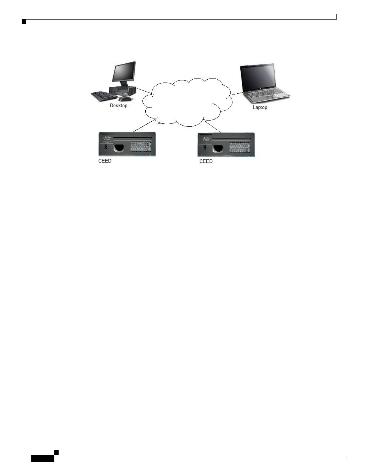
CEED 3700 series is a comprehensive integrated and open platform designed to leverage collaboration
and live content video to enable session. It is a high end reliable router with video conferencing
capability. It includes an intelligent edge device and leverages cloud capabilities of Cisco to deliver
secure, high definition video using the latest collaboration tools from the cloud.
1
Page 6
1-2
R E VIEW DR AFT
—
CISC O C O NFID E N TIAL
At one end CEED is connected. Other end can be a CEED, Desktop or Laptops
The CEED 3700 provides additional capabilities such as:
• 4th Generation Intel Processor.
• Operating temperature between (0°C to 40 °C).
• Projection lamp light brightness of 3000 Lumen fo r 4000 hours in standard mode and up to 6000
hours in Eco Mode.
• Field Re placeable Unit (FRU) based projection lamp.
• 3G Wireless Capability with Subscriber Identified Module (SIM)/ User Identify
Module
(UIM).
Page 7

Chapter 1 Introduction
Installation Prerequisites
R E VIEW DR AFT
—
CISC O C O NFID E N TIAL
1-3
Installation Prerequisites
This section describes how to install CEED 3700 unit, precautions, prerequisites and unpackin g of
CEED 3700 Components and Prerequisites
Note You need a minimum of /30 public IP pool provided the connection is coming directly on the Ethernet.
the CEED 3700 unit and contains the fo llowing sections:
• CEED 3700 Components and Prerequisites, page 1-3
• Safety Guidelines, page 1-4
• Usage Guidelines and Restrictions, page 1-5
The prerequisites and the required components to install the CEED 3700 are as follows:
• 100 V to 240V, 5 Amps Uninterrupted Power Supply (UPS)
• 1 Mbps Internet Leased Line (ILL) with static IP availability
In case where the connection is coming on serial link, you will need an Ethernet modem and this needs
a /29 Public IP pool.
• 3G SIM for 3G Internet Access
• Power Socket for CEED unit with required earthing.
• Manually retractable projection screen
• CAT-6 cable - approximately10 feet or as required at site
• Power socket for the speakers
• Coach Bolts
• Screw Driver Set
• Allen Key set
• Hammer and Drill Set (manual as well as power-driven)
Page 8
Chapter 1 Introduction
Usage Guidelines and Restrictions
REVIEW DRAFT — CISC O C O NFIDE NTIAL
1-4
Safety Guidelines
CEED 3700 series in a single package that contains the items that are listed in the table List of CEED
Warning Ensure that never use defective parts or test the equipment with different parts that are not
Warning Do not replace any part that are not listed in
Warning Read the installation instructions before connecting the system to the power source. If an item in
Caution Be aware of the size and weight of the CEED 3700 when mounting. Ensure that the mounting location
Warning This product requires short-circuit
Warning The plug-socket combination must be accessible at all times, because it serves as the
Warning Only trained and qualified personnel should be allowed to install, replace, or service this
Warning Covers are integral part of safety design of th e product. Do not operate without the covers
Warning The area must be known to be
Warning This equipment must be grounded. Never defeat the ground conductor or operate th e equipment in
3700 Package Items.
box is damaged or missing, contact your Cisco
can safely support the weight. Please use the appropriate type of screws, electric drills and screw drivers
to install the unit.
Read the installation instructions before connecting the system to the power source
building
main disconnecting device.
absence of a suitably installed ground conductor. Contact the appropriate electrical
authority or an electrician if you are uncertain that suitable grounding is
prerequisites
representative
(over-current)
installation. Install only in accordance with national and local wiring
nonhazardous
protection, to be provided as part of the
before installing, servicing, or replacing the
or in the unpacking section
available.
listed.
regulations.
equipment.
installed.
inspection
unit.
the
the
Page 9
Chapter 1 Introduction
Usage Guidelines an d Restrictions
R E VIEW DR AFT
—
CISC O C O NFID E N TIAL
1-5
Warning There is the danger of explosion if the battery is replaced incorrectly. Replace the battery only
the same or equivalent type
according
to th e
manufacturer's instructions
recommended
by the
manufacturer.
Dispose of used batteries
with
Warning Before using the CEED device, read the user's manuals to ensure correct usage. Incorrect handling
this product could possibly result in personal injury or physical damage. The
assumes
defined in
no
responsibility
these
manuals of this
for any damage caused by mishandling that is beyond normal usage
product
manufacturer
of
Caution Be cautious of high temperatures of the CEED. High temperatures are generated when the lamp is lit. It
could result in fire or burn. Use special caution in households where children are present.
Usage Guidelines and Restrictions
Warning This section describes the usage guidelines and restrictions while using CEED
Warning The warranty will be void if one or more points in this section is
Warning Do not change the user name or
Warning Do not install any third party software or update the system
• CEED 3700 is
• Do
not
operate
–
Abnormal op
elements or cables, pe
immediately
sure that the smoke or
because
• Do
not
disassemble or
–
Modification and/or disassembly of the equipment
–
• Do
not
give the
–
If the
electrical
not a permanent
CEED 3700
erations such
turn off the power switch and then disconnect the power plug from the power outl
this could
Never open the cabinet.
CEED
shock.
be dangerous.
modify.
CEED
any shock or
is shocked and/or broken, it could result
password.
storage
if a problem should occur.
as
smoke,
netration
of liquids or foreign
odor
has stopped, contact
impact.
device.
strange odor, no image, no sound, excessive
matter, etc. can
your
account manager. Never attempt to
or accessories could result
in an
cause a
injury, and
violated.
settings.
fire or electrical
in
continued use
3700.
sound,
damaged casing or
shock.In such case,
et. After making
make
repairs yourself
fire or electrical shock.
could result
in
fire or
Page 10

Chapter 1 Introduction
Usage Guidelines and Restrictions
REVIEW DRAFT — CISC O C O NFIDE NTIAL
1-6
–
If the
CEED
is shocked, immediately turn
outlet and
•
The
CEED 3700
brackets and accessories.
– Do
• Do
not touch the surface of the lens, air fans and ventilation openings during use or immediately
contact your Cisco
not pl
ace the
device
CEED
representative.
“must be”
Do
not place
on
an
installed on
CEED 3700
unstable, slant or
burn.
•
Ensure to give ample of ventilation space for the
• Do
not
operate
CEED 3700
CEED 3700
•
Avoid a high temperature operating
•
The heat could have adverse influence on the cabinet of the
CEED3700,
• Keep
• Do
not pl
–
Never block the air fan and ventilation
• Do
not
• Use
• Be
only the correct
–
Incorrect power supply could result
– Use
sure to connect with gr
–
Connect the gr
correct
•
Avoid a smoky, humid or dusty
–
Placing the
electrical
device every 4 hours for about
the remote control and other parts
enough space between the
ace any objects on or
cover the
CEED3700
power
only the correct
ound terminal of
power
cord; otherwise, fire or electric shock can
CEED 3700 in a
shock. High dust environment will also result in quick clogging
continuously for more than 4
environment.
CEED 3700
near
the lens, air fans and ventilation openings of the
with a tablecloth, etc. Do not place the
cord and the correct
power
outlet
depending on the indication on the
ound
wire.
AC
place.
smoke, a highly humid, dusty pl
shutdown.
– Do
not
place the
etc.).
Do
– Do
not
use a humidifier near the
•
Avoid Magnetism.
–
Avoid any magnetic
Security Devices, or other
manufacture etc.) Magnetic
3700,
which
shut
down.
•
The
CEED 3700
through the
• Do
power management options during the set
not
allow
CEED 3700
not place the
may
interfere with
should not go
CEED 3700
near a smoky, humid or dusty place
CEED3700
CEED3700.
contact that is not shielded or protected on or near the
CEED
accessory that contains magnetic material that has not been provided
objects
cooling
in
sleep mo de. Adjust your Power
to install updates automatically from
off the
power
a RCC
on
vibrant
switch, disconnect the power
or
equivalent
an
unstable
surface such
ceiling with
surface
as a
wobbly or
provided
inclined stand.
plug
from
mounting
the power
after use to prevent
CEED 3700
device.
hours. Ensure that you
turn off
the
30 minutes
CEED3700
in
direct sunlight or near a hot
device and other objects such
and other parts. Do
object
such
as
as walls.
not place the
heater,
etc
CEED3700.
openings.
power
in
fire or electrical
outlet.
CEED 3700
shock.
CEED
on a ca
rpet
3700and the
or
bedding.
safety
standard.
inlet of this unit with the ground terminal provided at the building using the
result.
outdoors.
may
cause
interruption
fans speed or stopping, and
ace, oily soot or corrosive gas
of the ventilation system an d
(ex. a
smoking space, a kitchen, a beach,
CEED3700
of the internal mechanical performance of the
may
cause the
Management
CEED3700
options
could result in fire or
itself.
(ie.,.
accordingly
result
in
Magnetic
by
the
CEED
to completely
up.
the Internet and
restart.
a
lamp
Page 11
Chapter 1 Introduction
CEED 3700 Hardware Summary
R E VIEW DR AFT
—
CISC O C O NFID E N TIAL
Item
Number
Size
Mounting kit (Top Side)
1
246x130x547 mm (low)
Mounting kit (Botto m Side)
1
210x200x625 mm (low)
CEED 3700
1
440x315x135 mm (low)
AC Power Cord
1
2.5 meters
Speakers one pair
1
NA
Speaker Ad apter
1
Available along speaker
Speaker Extension Cable
1
10 meters
Speaker to Speaker inter
connection cable
1
10 meters
Remote fo r projection
1
NA
Keyboard
1
Wireless Keyboard
Mouse
1
Wireless Mouse
1-7
CEED 3700 Hardware Summary
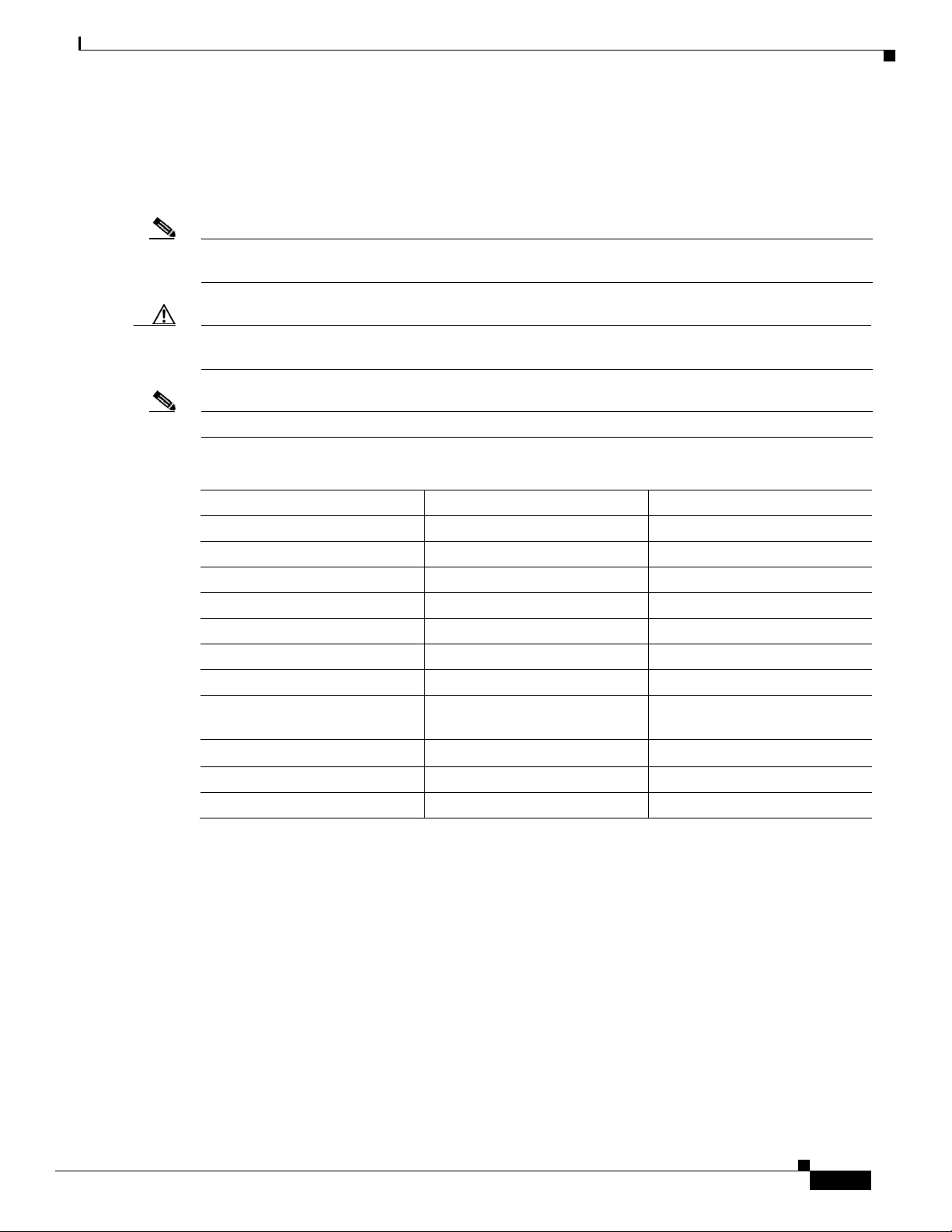
Note Ensure that all parts are in the package. Contact your Cisco representative within 2 weeks for any
Caution Do not use defective parts or use replacement parts that do not conform to specification. Make sure only
Note Keep the original packaging materials for future shipment. Ensure to use or iginal packaging material.
The table 1-1 describes the materials that are packaged with CEED 3700 unit in a single package.
missing parts.
authorized personnel can open the package.
Table 1-1 List of CEED 3700 Package
Items
Page 12
Chapter 1 Introduction
CEED 3700 Hardware Summary
REVIEW DRAFT — CISC O C O NFIDE NTIAL
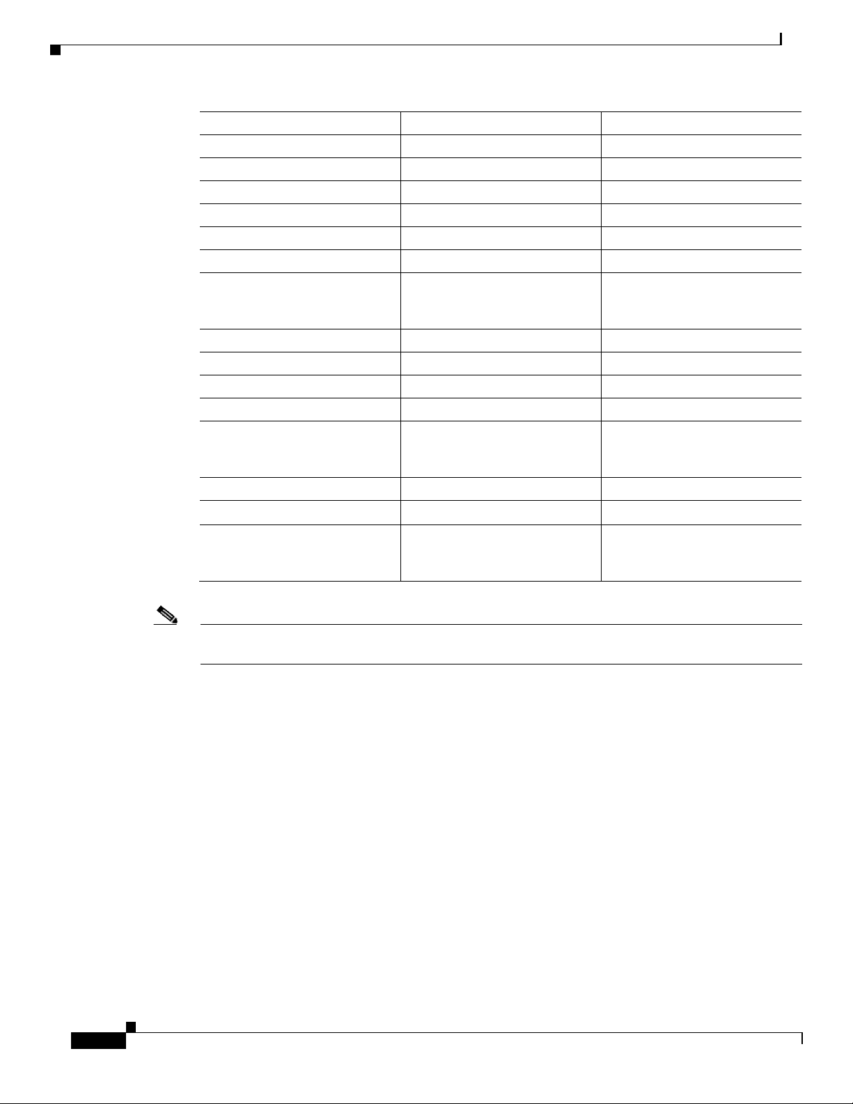
Item
Number
Size
Wireless Dongle
1
NA
Microphone
2
Wired microphone
Microphone Extension Cable
2
10 meters
Microphone Splitters
1
NA
Camera
2
Wired Camera
Active USB Extension Cable
2
10 meters
RJ45 cable from Router to
Mother board (Pre-installed in
the unit)
1
50 cm
Anchor Bolts
4
M 10
Allen Screws with was her
4
M 10 x 10 mm
Bolt with washer
2
M12 x 70 mm
Nut 2 M12
Router 3G Antenna*
2
Router Antennas (*Provided
only if 3G Option is selected
while ordering)
Wi-Fi antenna
1
Router Antenna
Remote Batteries*
1
3V, model:CR2025
Keyboard and Mous e Batteries*
3
2 AAA (keyboard batteries)*
and 1 AA (Mouse batteries)*
1-8
Note The batteries are either pre-installed or to be procured by the installation partner at the time of
installation.
Page 13

2-1
R E VIEW DR AFT
—
CISC O C O NFID E N TIAL
Installation
This chapter describes the installation/mo unting of the CEED3700 (CEED 3700) and contains the
following sections:
Mounting Prerequisites
Caution Ensure that all “Installation Prerequisites” section on page 1-2 in the Introduction chapter is adhered to
This section contains the foll owing sections:
• Mounting Prerequisites, page 2-1
• Mounting of the CEED 3700, page 2-1
• Accessories, Peripherals and Cable Assembly, page 2-6
• CEED 3700 is optimally designed for a room size of 20*20 ft. Any deviations shall be suitably
notified and prior approval on the installation with partners (The document assumes a size of 20*20
ft room. Actual position may vary depending on the implementation and other details)
• CEED is
• Ensure the celling is strong enough with reinforced concrete (RCC) or steel structures and is capable
of taking at least 20 Kilograms (Kg) of load.
• Ensure ambient room lighting for proper image capture and better image projections.
• Use
without any deviations.
placed at
drapes or opaque curtains to block excess
10
to
13
feet from the
screen.
light
C H A P T E R
in
the room that will interfere the
2
image
projection.
Mounting of the CEED 3700
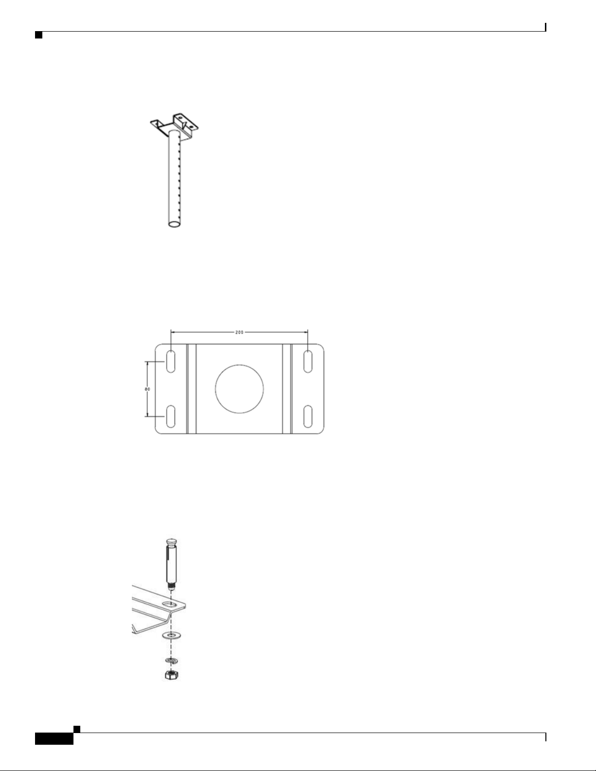
Step 1 Assign the position of the CEED (from the screen) to be mounted. Align/arrange the top portion of the
To mount the CEED 3700 in the ceiling, perform the following steps:
mounting kit towards the ceiling as shown in “Top portion of the Moutning Kit” in Figure 2-1.
Remove the portion after you mark the holes.
Page 14
Chapter 2 Installation
2-2
REVIEW DRAFT — CISC O C O NFIDE NTIAL
Figure
2-1
Top portion of the Moutning
Kit
• Alternatively, you can also mark the holes using the template markings as shown in “Template for
the Drilling Hole” in Figure 2-2.
Figure
2-2
Template for the Drilling
Hole
Step 2 Drill 12 mm diameter for the depth of 55 mm holes at the marked position.
Step 3 Insert all 4 anchor bolts one-by-one and slightl y hammer to drive anchor into the drilled holes. Fix the
top portion of the mount ing kit and tighten the screws using the wrench/heavy dut y screwdriver. See
“Fixing of the Anchor Bolts” in Figure 2-3.
Figure
2-3
Fixing of the Anchor
Bolts
Page 15
Chapter 2 Installation
2-3
R E VIEW DR AFT
—
CISC O C O NFID E N TIAL
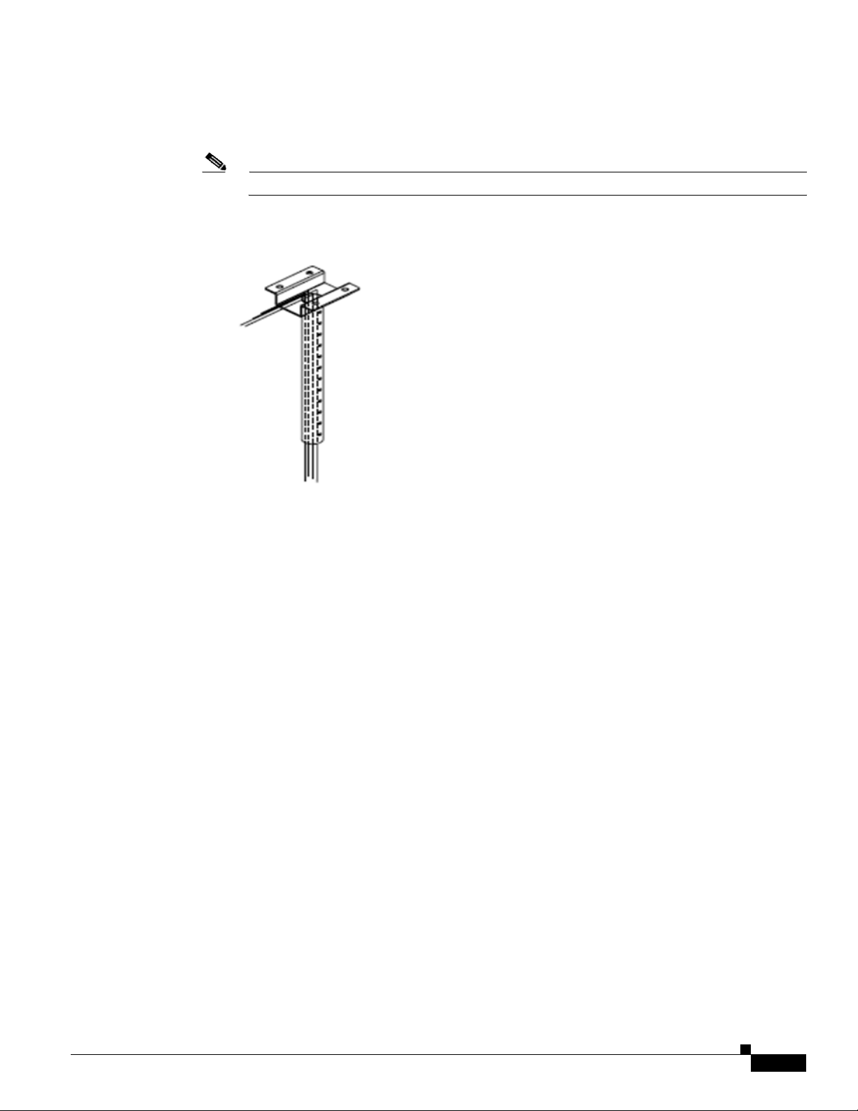
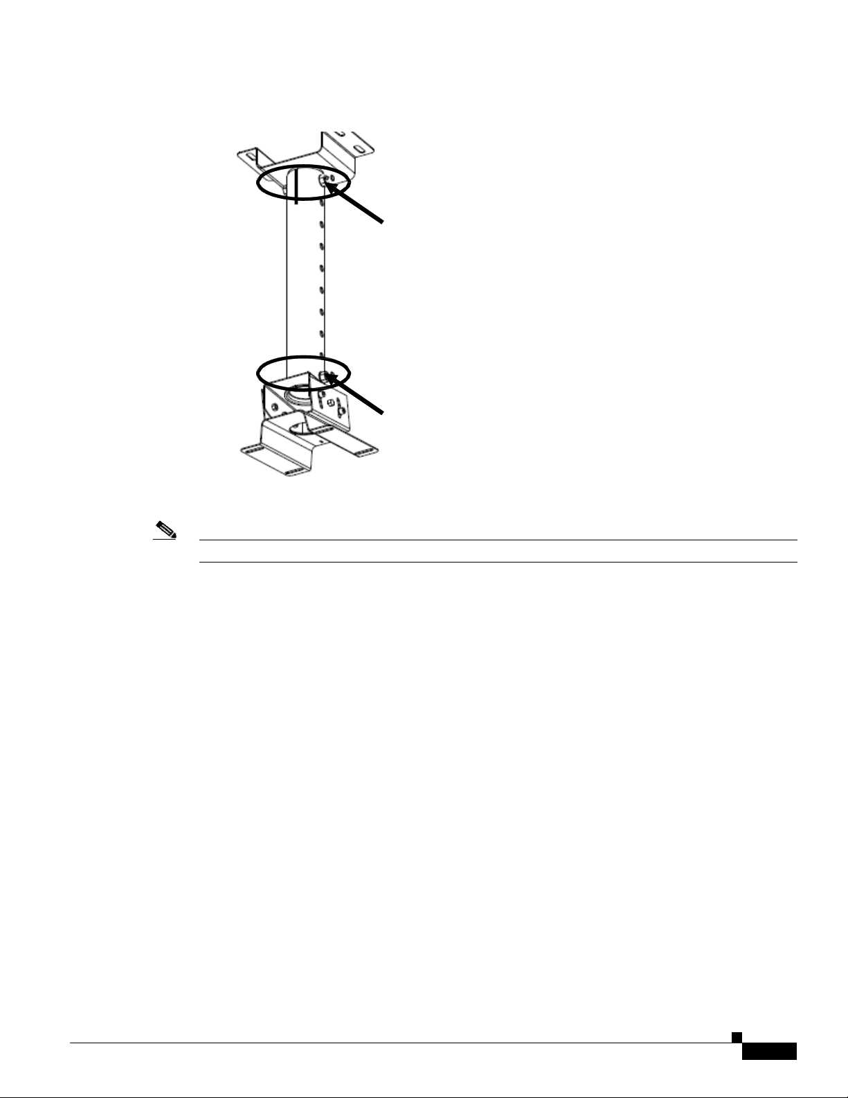
Step 4 To connect all the cables, draw all the cables that are mentioned in “List of CEED 3700 Package
through the pipe and pull them towards the top portion of the mo unting kit. See Figure
2-4.
Note Ensure that respective end of cab les pass through the mounting kit from the bottom.
Figure
2-4
Cable Connections through the Mounting
Kit
Items”
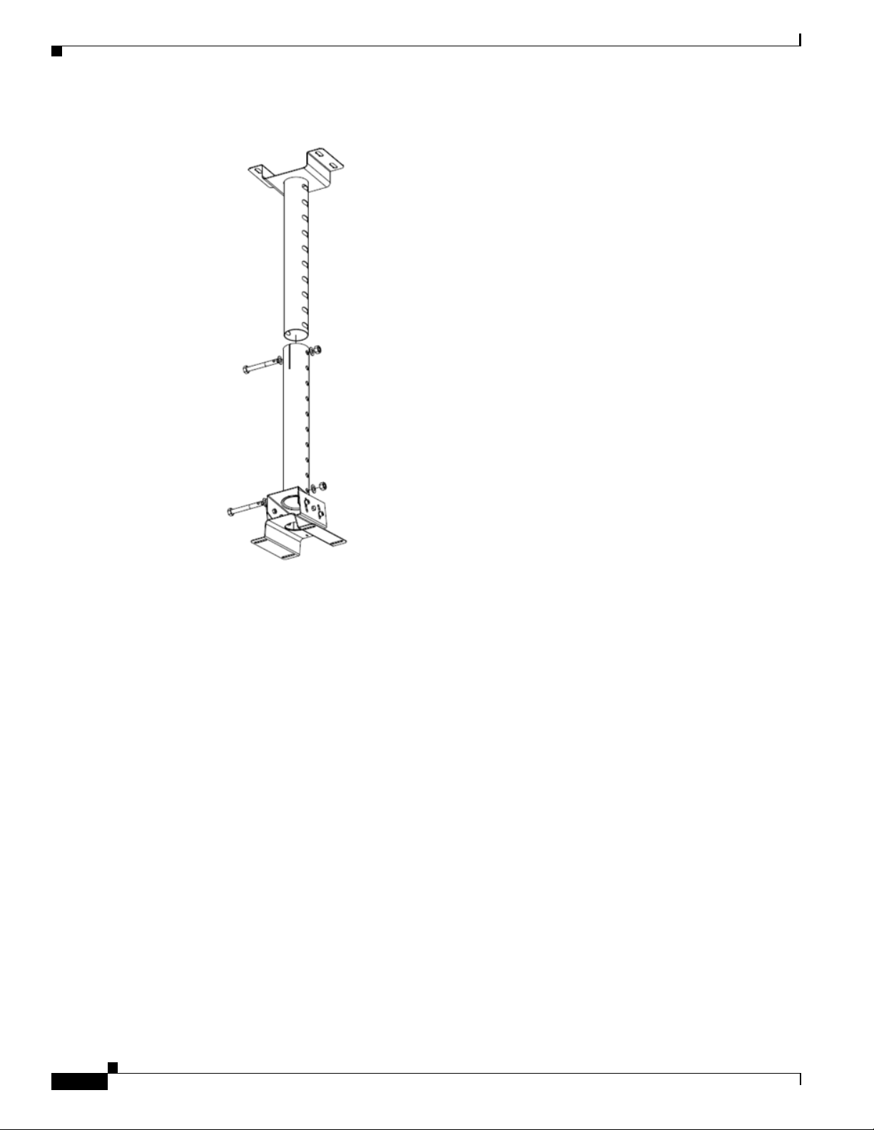
Step 5 Insert bottom portion of mounting kit to top portion of the mounting kit as shown in “Alig nment of
Step 6 Adjust the length of the vertical slider so that the base of the CEED 3700 is above 6 feet from the
Top Portion and the Bottom Portion of the Mounting Kit”.
the
ground.
Page 16
Chapter 2 Installation
2-4
REVIEW DRAFT — CISC O C O NFIDE NTIAL
Figure
2-5
Alignment of the Top Portion and the Bottom Portion of the Mounting
Kit
Step 7 Lock the Vertical Slider in both top and bottom side of the mounting kit. See Figure 2-6
Page 17
Chapter 2 Installation
2-5
R E VIEW DR AFT
—
CISC O C O NFID E N TIAL
Figure
2-6
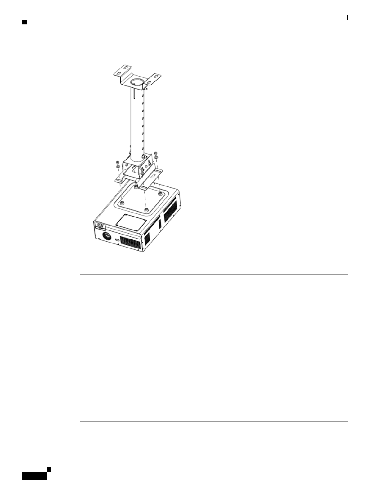
Step 8 Place CEED 3700 unit as shown in figure“CEED 3700 Placement”in Figure 2-7.
Locking the Vertical
Slider
Note Ensure that the lens of the CEED 3700 is facing the screen.
Step 9 Lock the screws tightly.
Page 18
Chapter 2 Installation
2-6
REVIEW DRAFT — CISC O C O NFIDE NTIAL
Figure
2-7
CEED 3700
Placement
Step 10 Complete set up looks as shown in
Accessories, Peripherals and Cable Assembly
This section describes the external wiring, all cable connections, positioning of the accessories and their
External Wiring and Placement of Accessories
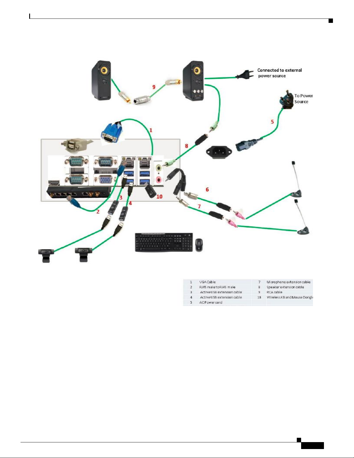
Step 1 To connect accessories such as camera, microphone, keyboard, mouse and speaker follow the “CEED
3700 External Cable Connections” in Figure 2-9.
connections and contains the following section:
• External Wiring and Placement of Accessories, page 2-6
• Assembling of the Accessories, page 2-8
To connect and place all the accessories, peripherals and cables that are coming out of the CEED
3700 device, perform the fo llowing steps:
Note: The accessories and peripherals should be kept outside the test chamber/room using the extension cables while
performing any compliance test.
Page 19
Chapter 2 Installation
Accessories, Peripherals and Cable Assembly
R E VIEW DR AFT
—
CISC O C O NFID E N TIAL
2-7
Figure 2-9 CEED 3700 External Cable
Connections
Step 2 Allocate appropriate positions to the accessories.
Page 20

REVIEW DRAFT — CISC O C O NFIDE NTIAL
2-8
Assembling of the Accessories
VGA
Camera
Speakers
Step 1 Connect the Camera 1 and Camera 2 to Ac tive USB extension cable. Refer number 3 and number 4 in
Step 2 Insert the USB extension cable in the USB port in the CEED 3700 back panel as shown in Figure 2-9
Step 3 Place the camera in the appropriate position.
Step 4 Secure the camera position with appro priate nuts, bolts and screws.
Step 1 Connect the speakers to the audio extension cable.Refer number 8 and number 9 as shown in Figure 2-9.
Step 2 Insert the audio extension cables in Audio port (Lime Color).
Step 3 Place the speakers at a suitable height on the wall fo r the sound to be audible as shown in Figure 2-9.
Step 4 Secure the speakers with appropriate brackets and screws.
Step 5 Connect the speakers to the power outlet.
Note The power cord provided with the speakers in the CEED 3700 package items are to be used only in India.
This section describes how to connect camera, micropho ne and speakers to CEED 3700.
Connect the VGA cable to the CEED back panel VGA port. Refer number 1 in
To connect the camera 1 and camera 2 to the CEED 3700 back panel, perform the following steps:
Figure 2-9 for connection.
To connect the speakers to the
CEED 3700
Note that the height will differ at each site.
For other countries use your respective adapters/converters for the power cord.
back panel, perform the following
steps:
Figure
2-9
Page 21

Chapter 2 Installation
Accessories, Peripherals and Cable Assembly
R E VIEW DR AFT
—
CISC O C O NFID E N TIAL
2-9
Microphone
Step 1 Connect the microphone splitter to the microphone. Refer number 6 and number 7 as shown in
Figure 2-9.
Step 2 Connect the microphone extension cable to the splitter.
Step 3 Connect the microphone wire to the other end of the microphone extension cable
Step 4 Insert audio extension cables into Audio port (Pink Color).
Step 5 Place the microphones at suitable locations such that it is easily accessible as shown in Figure 2-9.
Keyboard and Mouse
CEED 3700
port of the
Screen
To
connect the projection screen to the
Step 1 Vertically place the screen parallel to the wall. Placement of the screen should be such that the lens of
Step 2 Secure the screen to the wall with screws.
the CEED 3700 projects on the screen.
Note Screen is not part of the CEED 3700 package items. To be procured by the installation partner.
comes with the wireless keyboard and wireless mouse.
CEED 3700
back panel. Refer number
CEED 3700,
10 as
shown
perform the following
Plug-in the
in Figure 2-9.
steps:
appropriate
respective
dongle
in
the
USB
Page 22

REVIEW DRAFT — CISC O C O NFIDE NTIAL
3-1
Configuring LA N and Connectivity
This chapter describes the how to configure Local Area Network and its related connectivity to the
Configuring LAN
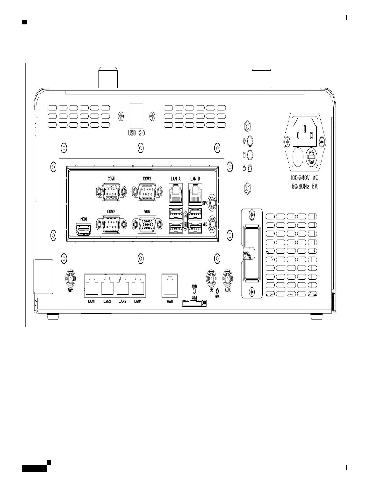
Step 1 Connect RJ45 cable from the modem to the CEED 3700 WAN port in CEED 3700 back panel.
CEED 3700 device and how to power on the CEED 3700. This chapter contains the following sections:
• Configuring LAN
• Powering On CEED 3700
To connect the RJ45 cable to the specific ports, perform the following steps:
C H A P T E R
3
Page 23
3-2
REVIEW DRAFT — CISCO CON
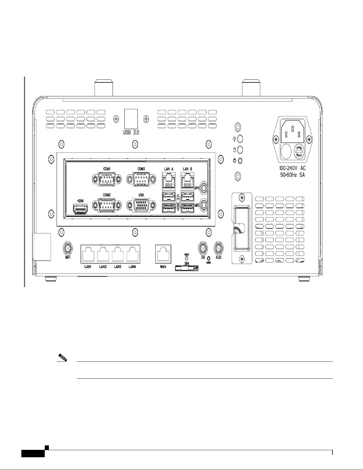
Figure
3-1
CEED 3700 Back P
anel
FIDE NTIAL
Step 2 Connect RJ 45 cable provided wit h the CEED 3700 package item fr om LAN1 port in the back panel to
Step 3 Connect the Wi-Fi Antenna to the Wi-Fi Antenna port.
Step 4 Connect the one 3G Antenna to 3G port.
Step 5 Connect the other 3G antenna to the AUX port.
Step 6 Insert a 3G SI M in the SIM slot.
the LAN A port. See CEED 3700 Back Panel in Figure 3-1.
Note RJ45 cable from the modem to CEED 3700 is not provided with the CEED packaging items. The
deployment partner has to procure the RJ45 cable as the length may be different in each location.
Page 24
REVIEW DRAFT — CISC O C O NFIDE NTIAL
3-3
Chapter 3 Configuring LAN and Connectivity
Powering On CEED 3700
Powering On CEED 3700
Caution All cables, peripherals and accessories to be connected securely before power-on.
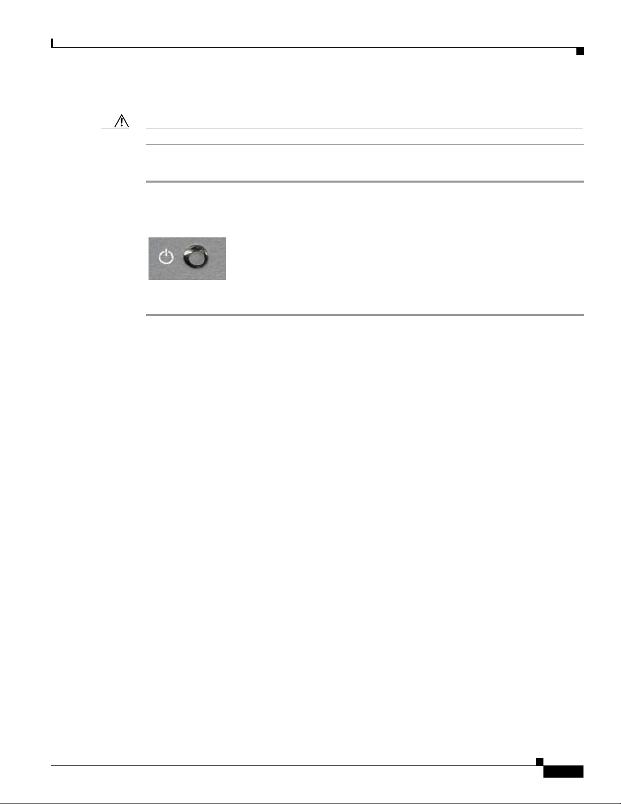
Step 1 Press the power switch once. See Power Switch in Figure 3-2.
Step 2 Turn on the projection system using the remote or the projection ON/OFF switch at the bottom of CEED
This section describes how to power on the
Figure
3-2
3700.
Power
Switch
CEED 3700
after connecting the
power cord.
Page 25
A
4-1
REVIEW DRAFT — CISCO C O
NFID ENTIAL
Configuring CEED 3700 Software
This chapter describes how to configure the CEED 3700 software, first time login and subsequent login
sessions using the CEED 3700. This configuration is a one-time process to be performed during the first
time login only.
Note The fo llowing sections assumes that you have removed the plastic sheet covering the back panel of
CEED 3700 and CEED 3700 powered on.
First Time Log in
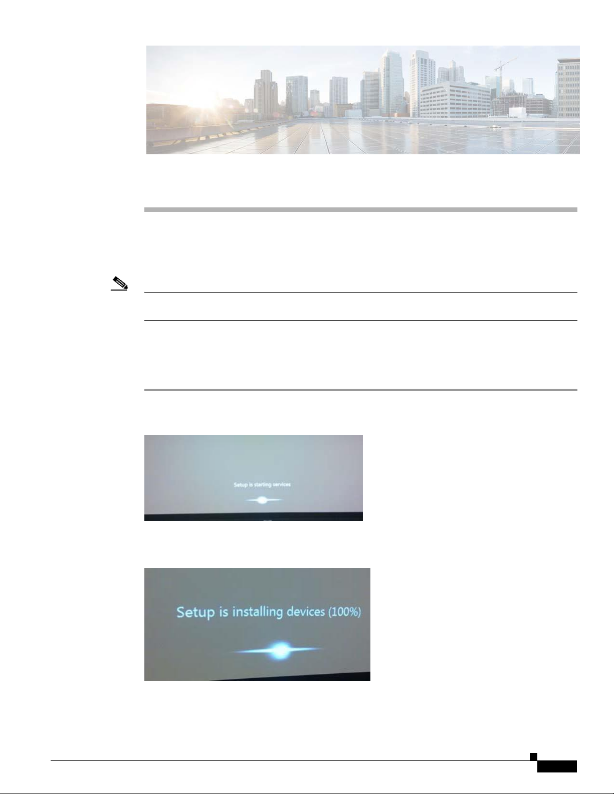
Step 1 After you power on the setup screen will appear as shown in “Setup Screen” figure Figure 4-1
To complete the configuration of CEED 3700, perform the fo llowing steps after you first login.
Figure
4-1
Setup
Screen
C H A P T E R
4
the
Step 2 Wait for 20-30 seconds for the setup process screen to appear as shown in “Setup Process” in Figure 4-2
Figure
4-2
Step 3 Once the system has installed the required devices 100%, Windows 7 professional license starts its
installation process. The windows 7 licence screen as appears.
Setup
Process
Page 26

Chapter 4 Configuring CEED 3700 Software
4-2
REVIEW DRAFT — CISCO C O
NFID ENTIAL
Step 4 From the Co untry or region drop-down list, choose India.
Step 5 From theTi me and Currency drop-down list, choose your country. For example, English (India)
Step 6 From the Keyboard layout drop-down list, choose US and clic k Next.
For Steps 4 to 6 see figure Figure 4-3.
Figure
4-3
Windows 7 License
Screen
Step 7 Enter the desired Username. For example, CEED.
Type the computer name filed will auto-populate with the “username-PC”. For example CEED-PC.
See Figure 4-4.
Figure
4-4 Username
Step 8 Click Next. Set a Password for your account screen appears. See Figure 4-5.
Page 27
Chapter 4 Configuring CEED 3700 Software
4-3
R E VIEW DR AFT
—
CISC O C O NFID E N TIAL
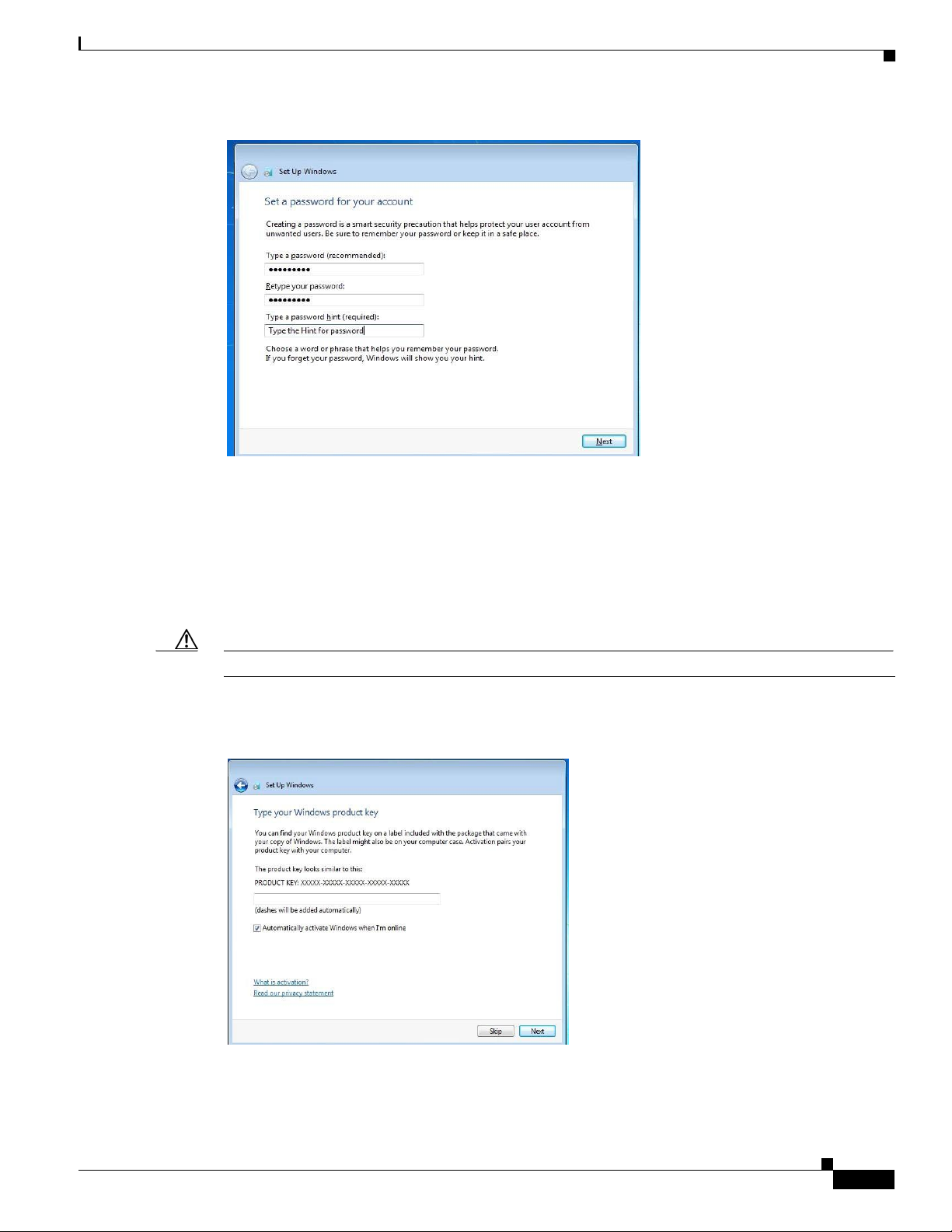
Figure
4-5
Set a password for your account
Step 9 In the Type a Password field, type a password. For example, xyzabc
Step 10 Re -type your password, in the Re-Type password field.
Step 11 (Optional) Enter the hint for your password.
Step 12 Click Next.
Step 13 Type your Windows Product Key screen appears. See Figure 4-6
Step 14 Click Skip.
Caution Do not enter the product key
Step 15 Uncheck the Automatically activate windows when I’m Online check box.
Figure
4-6
Product
Key
Step 16 Check the radio button I accept the license terms and then click Next. See Figure 4-7
Page 28

Chapter 4 Configuring CEED 3700 Software
4-4
REVIEW DRAFT — CISC O C O NFIDE NTIAL
Figure
4-7
Step 17 Click Next.
Step 18 Review your Date and Time settings on the wind ow that appears as shown in “Set Date and Time” in
Figure 4-8.
Figure
4-8
Accepting Windows
Set Date and
Time
Licence
Step 19 Set your Time Zone. For example, (UTC +5.30) Chennai, Kolkata, Mumbai, New Delhi, if you have
Step 20 Set the current Date and Time.
Step 21 Click Next.
Step 22 Select Public network from select your computer's current location. See Figure 4-9
selected India as your country in Step 4.
Page 29

Chapter 4 Configuring CEED 3700 Software
4-5
R E VIEW DR AFT
—
CISC O C O NFID E N TIAL
Note This Window will not appear if LAN is not connected to CEED 3700. Select Public network whenever
LAN cable is connected
Figure
4-9
Set Up
Windows
Step 23 Windows Desktop Screen with windows logo appears see “Windows Desktop” in Figure 4-10.
Figure 4-10
Windows
Desktop
Step 24 Click the Start button, enter “Microsoft Security Essentials” in the search box, and open “Microsoft
Security Essentials” application. See Figure 4-11.
Page 30

Chapter 4 Configuring CEED 3700 Software
4-6
REVIEW DRAFT — CISC O C O NFIDE NTIAL
Figure 4-11
Search
Box
Step 25 Wait for a few seconds before Microsoft Security Essentials screen pop up on the desktop as shown in
Figure 4-12.
Figure
4-12
Microsoft Security
Essentials
Step 26 Click Update tab to update the latest Virus and Spyware definition.
Note Ensure that CEED 3700 is connected to the Internet while you perform the Step 26.
Page 31

Chapter 4 Configuring CEED 3700 Software
4-7
REVIEW DRAFT — CISC O C O NFIDE NTIAL
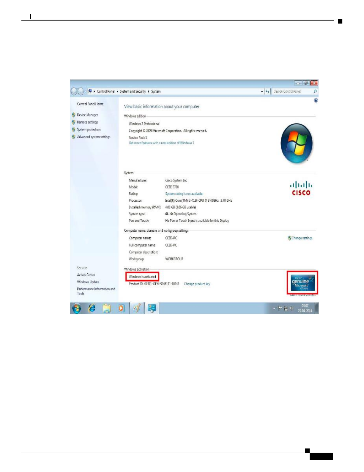
Step 27 To activate windows right-click on My Computers and then choose Properties from the drop-down
menu. See Figure 4-13.
Figure
4-13 Properties
A System Screen appears where you can change the product key. See Figure 4-14.
Figure
4-14
System
Screen
Step 28 To change the product Key, click Change Product key.
A Windows Activation Screen appears. See Figure 4-15.
Page 32
Chapter 4 Configuring CEED 3700 Software
4-8
R E VIEW DR AFT
—
CISC O C O NFID E N TIAL
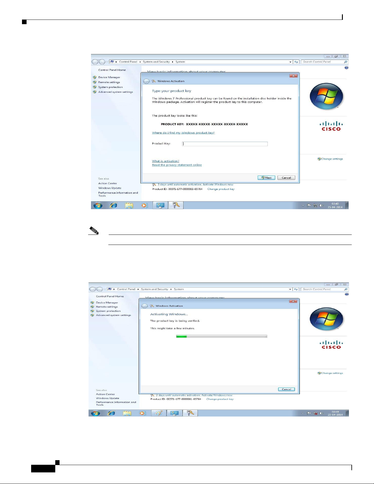
Figure 4-15
Windows Ac
tiv
ation
Step 29 Enter the Product Key in the Product key
field.
Note The product key is an alphanumeric key whic h is found in the CEED Box
A Windows Activation with activating windows appears. See Figure 4-16.
Figure 4-16
Activating
Windows
Page 33
Chapter 4 Configuring CEED 3700 Software
4-9
REVIEW
DRAFT-CISCO CONFIDENTIAL
After
a few
Step 30
Figure 4-17 Activated
minutes
the
Windows
Windows
is
activated
screen appears
as
shown
in
Figure 4-17
Page 34

5-1
R E VIEW DR AFT
—
CISC O C O NFID E N TIAL
Configuring th e Browser
This chapter describes about how to configure the CEED3700 (CEED
Launching the Browser
Step 1 Power on the CEED 3700 device by pressing the Power Switch once.
Step 2 Enter the Username in the Username field. For example, Cisco
Step 3 Enter the Password in the pass word field. For example, 1234
Step 4 Click the Internet Explorer e icon to launch the browser
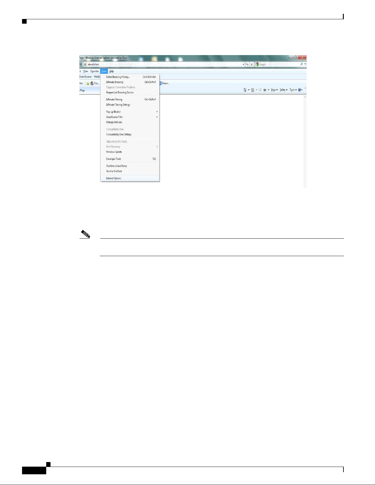
Step 5 From the browser menu bar, click Tools. (See Figure Figur e 5-1)
3700 browser (Internet Explorer 8.0) and contains the following sections
• Launching the Browser, page 5-1
• Verification of the Browser Settings, page 5-3
To launch the browser in CEED 3700, perform the following steps:
Alternatively, you can press Alt + F simultaneousl y in your keyboard to open the Tools Menu.
C H A P T E R
5
Page 35
5-2
REVIEW DRAFT — CISC O C O NFIDE NTIAL
Figure
5-1
Step 6 From Tools menu, choose Internet Options. (See Figure 5-1Tools Menu)
Step 7 Click Internet Options.
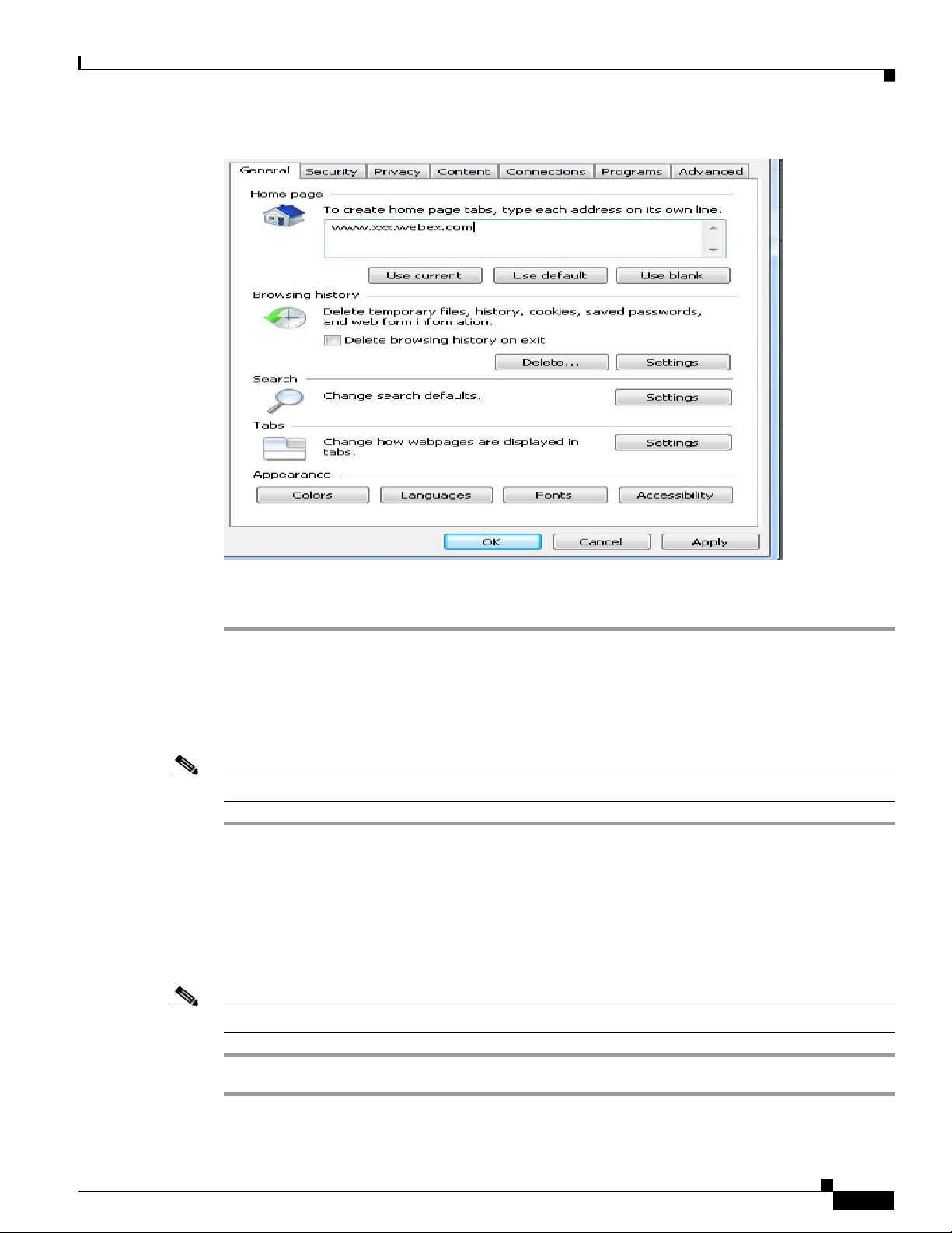
A Internet Options dialog box opens. (See Figure 5-2Internet Options)
Step 8 Enter the homepage address or URL in the homepage field. For example,
Note This URL or homepage address will be provided by the Cisco Representative or the partner
during the installation.
Tools
Menu
http://kssa.webex.com
Page 36
5-3
Chapter 5 Configuring the Browser
Figure
R E VIEW DR AFT
5-2
Internet
Options
—
CISC O C O NFID E N TIAL
Step 9 Click OK.
Step 10 Restart the browser.
Verification of the Browser Settings
Note Ensure the CEED 3700 device is powered ON. If no t power ON the CEED device as given in Step 1.
Step 1 Check the Back Panel LED indicators functionality which is as follows:
Step 2 To login to enter the Username and password.
Step 3 Click the Internet Explorer icon e to launch the browser
Note If the default page does not open, repeat the tasks in Launching the Browser section.
To verify your browser settings, perform the following steps:
• Link LED glow continuously
The homepage (CEED Page) must open with your default address/URL that you have set in Step 8 of
last section.
Page 37

6-1
R E VIEW DR AFT
—
CISC O C O NFID E N TIAL
Configuring th e Router
This chapter describes how to configure the router for the CEED 3700. This chapter contains the
Configuring WAN
Step 1 Connect RJ45 cable from the modem to the CEED 3700 WAN port in CEED 3700 back panel.
Step 2 Connect RJ 45 cable provided with the CEED 3700 package ite m fr om LAN1 port in the back panel to
following:
• Configuring WAN
• Configuring 3G
• Configuring Wi-Fi
• Powering Down/Shutting Down the CEED 3700
This chapter assumes that the following prerequisites have been completed.
• At least 1 Mbps Internet Leased Line with Static Public IP for WAN interface is available.
• The Internet link should have an Ethernet hand-off.
To configur e the WAN in the router, perform the following steps:
the LAN A port. See CEED 3700 Back Panel in Figure 6-1.
C H A P T E R
6
Page 38
Chapter 6 Configuring th e Router
Configuring WAN
REVIEW DRAFT — CISC O C O NFIDE NTIAL
6-2
Figure
6-1
CEED 3700 Back
Panel
Step 3 Click Wind ows Start button, choose All Programs and then click Internet Explorer to open the web
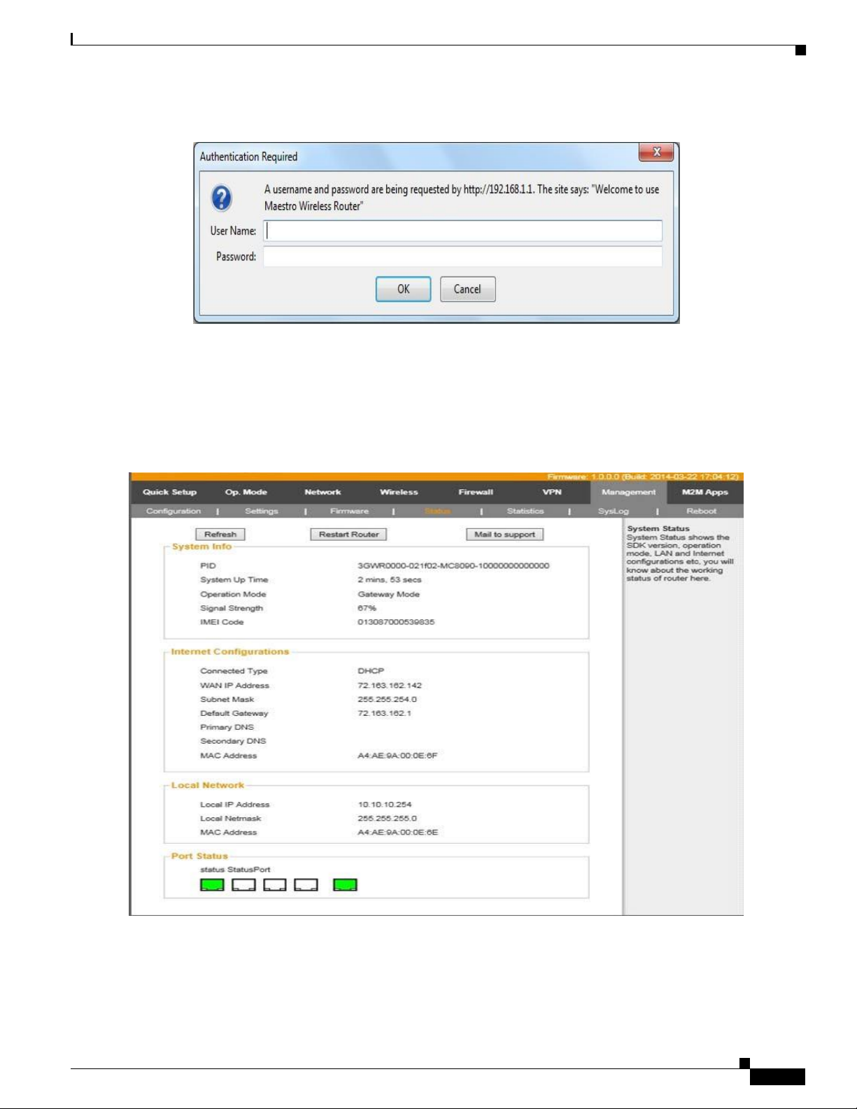
Step 4 Enter the IP address of the router in the web address bar and then press Enter. The default IP address is
browser.
192.168.1.1.
An Authentication required dialog box appears as shown in Figure 6-2.
Page 39
Chapter 6 Configuring the Router
Configuring WAN
R E VIEW DR AFT
—
CISC O C O NFID E N TIAL
6-3
Figure
6-2 Authentication Required
Step 5 Enter the Username and password in the Username and password field respectively. The default
Step 6 Click OK.
Step 7 The Router homepage appears as shown in “Router Home Page” in Figure 6-3.
username is ad min and the password is admin
Figure
6-3
Router Home
Page
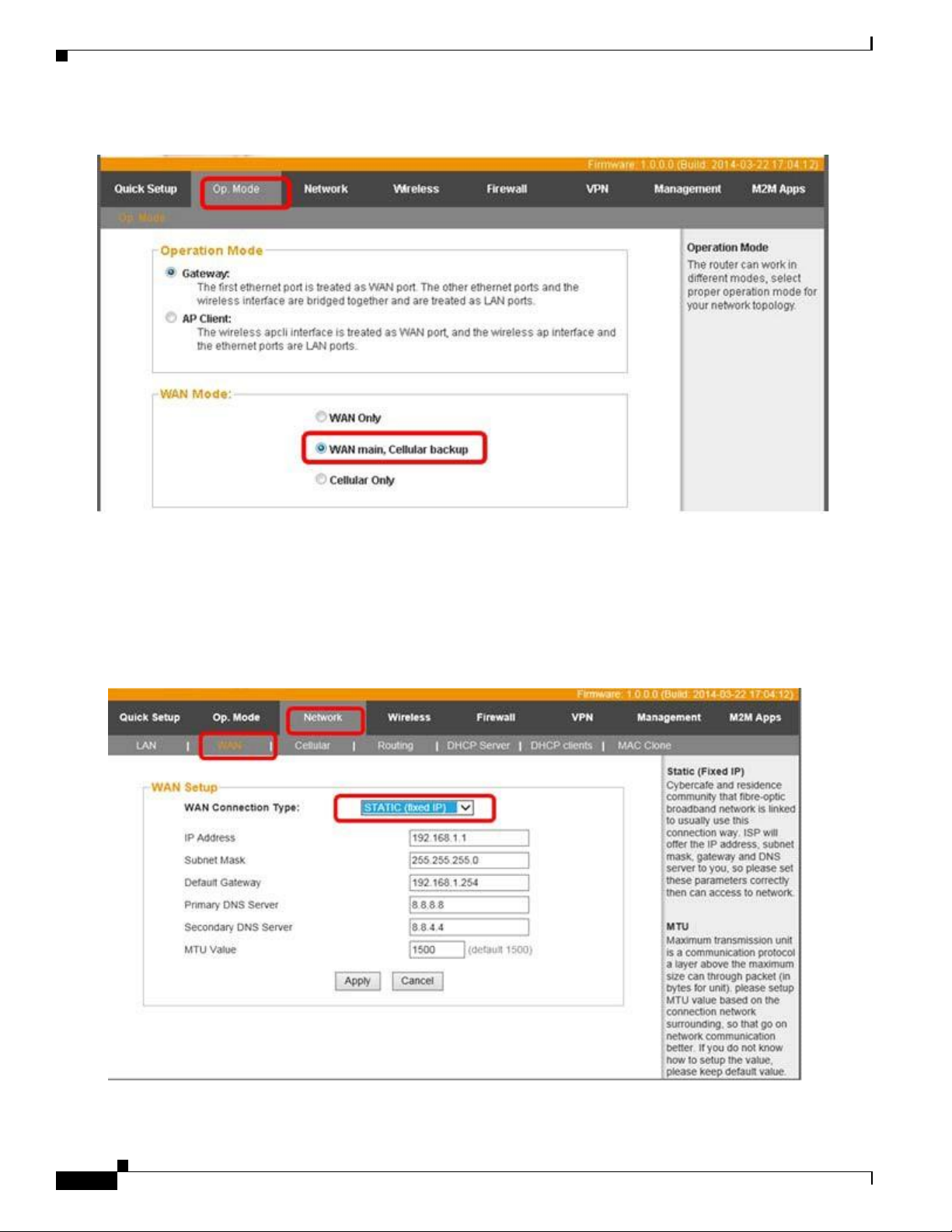
Step 8 Cick Op.mode tab to change the WAN mode to WAN Main, Cellular Back up.
Step 9 Select the WAN Main, Cellular Back up radio button as shown in “Op.Mode”in Figure 6-4.
Page 40
Chapter 6 Configuring th e Router
Configuring WAN
REVIEW DRAFT — CISC O C O NFIDE NTIAL
6-4
Figure
6-4 Op.Mode
Step 10 Click Ap ply and then wait for the settings to be applied.
Step 11 Press F5 to refresh the browser.
Step 12 Click Network tab, choose WAN to set up the static IP on WAN.
The router page as shown in Figure 6-5 appears.
Figure
6-5
Network
Tab
Step 13 From the WAN Connection Type drop-down list, choose STATIC (Fixed IP)
Page 41
Chapter 6 Configuring the Router
Configuring 3G
R E VIEW DR AFT
—
CISC O C O NFID E N TIAL
6-5
The IP Address, Subnet Mask, Default Gateway, Primary DNS Server, Secondary DNS Server and MTU
Step 14 Enter the values that you have obtained from the Service Provider in the IP address, Subnet Mask,
Step 15 The MTU Value is set to default 1500.
Step 16 Click Apply and wait fo r the settings to be applied.
value fields will be enabled.
Default Gateway, Primary DNS Server, Secondary DNS Server.
Configuring 3G
Step 1 Perform Step 1 to Step 7 in the section Configuring WAN, page 6-1.
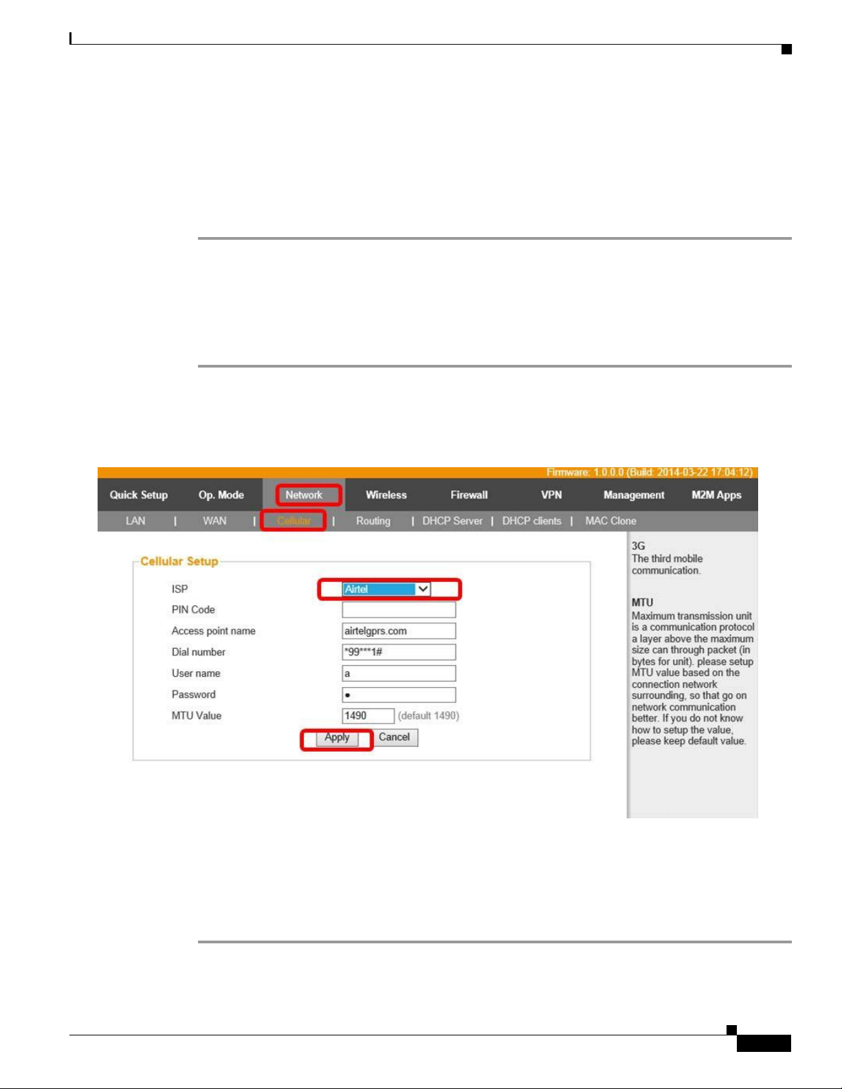
Step 2 Click Network tab and then choose Cellular as shown in “Cellular Tab” in Figure 6-6.
To configur e 3G network in the router, perform the following steps:
Figure
6-6
Cellular
Tab
Step 3 From the IPS dro p-down list, choose the service provider. For example, Airtel.
Step 4 If your Service provider is not listed in the drop-down menu, enter the service provider’s name manually.
Step 5 In the Access point name, dial numb er , us er name and password fields enter the respective values
Step 6 Click Apply and wait for the changes to be applied.
provided by the service provider.
Page 42

Chapter 6 Configuring th e Router
Configuring Wi-Fi
REVIEW DRAFT — CISC O C O NFIDE NTIAL
6-6
Configuring Wi-Fi
Step 1 Perform Step 1 to Step 7 in the section Configuring WAN, page 6-1.
To configure Wi-Fi set up in the router, perform the following steps:
Click Wireless tab and then choose Basic as shown in “Wireless Tab” in Figure 6-7.
Figure
6-7
Wireless
Tab
Step 2 In the SSID field, enter Cisco-CEED.
Step 3 Click Apply and then wait for settings to be applied.
Step 4 Press F5 to refresh the browser.
Step 5 Click Wireless Tab to change the Wi-Fi password
Page 43
Chapter 6 Configuring the Router
Powering Down/Shutting Down the CEED 3700
R E VIEW DR AFT
—
CISC O C O NFID E N TIAL
6-7
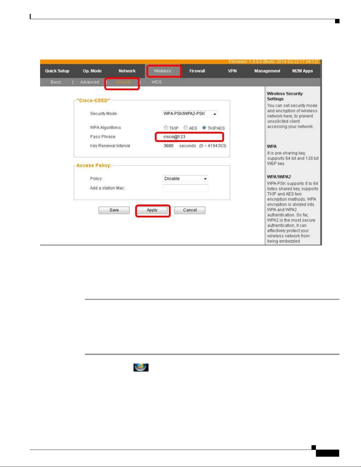
Figure
6-8
Wireless
Tab
Step 6 Click Security.
Step 7 In the Pass phrase field, enter cisco@123 to set the password.
Step 8 Click Apply and wait for the changes to be applied.
Step 9 Press F5 to refresh the browser.
Step 10 Re boot the CEED 3700 device.
Powering Down/Shutting Down the CEED 3700
To shut down the CEED 3700 device, perform the following tasks:
Step 1 Close all applications and wait for all applicatio ns to shutdown
Step 2
Step 3 Click Shut down.
Step 4 Wait for the display to turn off.
Step 5 Wait for the projection fan to stop (Step 1 and Step 4 will take about 2-3 minutes)
Click Start button
Step 6 Tum off the AC Power Switch in the wall power
outlet.
Page 44

Chapter 7 Configuring the Live Session
7-1
7
R E VIEW DR AFT
Configuring th e Live Session
This chapter describes how to schedule and join the live session. It also describes about the accessories
that are enabled during a session and troub leshooting techniques. This chapter includes the following
sections:
• Hosting a WebEx Session
• Joining a WebEx Session
• Verification of the Accessories
—
CISC O C O NFID E N TIAL
C H A P T E R
Hosting a WebEx Session (HOST)
Step 1 Log into WebEx Meeting Center site: http://kssa.webex.com
Step 2 Click on My WebEx.
Step 3 Log into WebEx account using the following credentials:
User Name: hoskote
Password: Edu@123
Step 4 Click on Meeting Center.
Step 5 Click on Schedule a Meeting (Marked in Red in the below figure).
Page 45

Chapter 6 Configuring the Router
Powering Down/Shutting Down the CEED 3700
R E VIEW DR AFT
—
CISC O C O NFID E N TIAL
7-2
REVIEW DRAFT — CISC O C O NFIDE NTIAL
Step 6 Enter a Meeting Topic (For example: Test).
Step 7 Set Session password as 1234 and confirm the same.
Step 8 Set date and time.
Step 9 Audio conference type should always be “Use VoIP only”.
Step 10 Click on Start Now. . This will start the WebEx session.
Note: If this is the first time WebEx is running on your computer, you will be prompted to install
the WebEx software via ActiveX. Install it.
Step 11 Turn on the video by clicking the video icon
Step 12 Note the Meeting number (marked in Red).
Page 46

Chapter 7 Configuring the Live Session
7-3
REVIEW DRAFT — CISC O C O NFIDE NTIAL
Joining a WebEx Session (Participant / Attendee)
Step 1 Log in to WebEx Meeting Center site: http://kssa.webex.com
Step 2 Click on Meeting Center.
Step 3 Note down the Meeting number from the Meeting Info tab in Host login (Refer Step 12 of
Hosting a WebEx Session).
Step 4 Enter the Meeting number (in the box marked in Red) and click Join Now (marked in Blue).
Step 5 Enter the required login info: Name, email and password. Password will be 1234 (Refer Step 7
of Hosting a WebEx Session).
Page 47

Chapter 6 Configuring the Router
Powering Down/Shutting Down the CEED 3700
R E VIEW DR AFT
—
CISC O C O NFID E N TIAL
7-4
REVIEW DRAFT — CISC O C O NFIDE NTIAL
Step 6 Click on Join. This will start the WebEx session for attendee.
Note: If this is the first time WebEx is running on your computer, you will be prompted to install
the WebEx software via ActiveX. Install it.
Step 7 A pop up to Join the Integrated Voice Conference appears. Click on Yes.
Step 8 Turn on the video by clicking the video icon
Note: This document is grounded on WebEx Meeting center. If WebEx Training center is used, the only
change would be to click on Training center instead of Meeting center (wherever applicable).
Verification of the Accessories
To verify the accessories (Camera/Microphone) perform the following steps:
Step 1 Microphone 1 and 2 on CEED 3700 is audible on the speakers. Both microphones are tested for its
Step 2 Verify the camera image is visible on the training screen (projection screen) of CEED 3700
individual effect.
a. If the microphone is not audible, make sure you have selected the right microphone.
b. Click Audio from the menu bar, choose the appropriate microphone from the drop-down menu to
make the microphone audible.
If the above steps does not seem to work, troubleshoot with the following
c. Click windows Start button. Choose Control Panel.
Adjust your computer settings window appears.
d. Click Hardware and Sound.
e. From the list, click Sound.
A sound dialog box appears
f. From the playback tab, choose the appropriate output and click OK.
g. From the Microphone tab, choose the appropriate Microphone output and click OK.
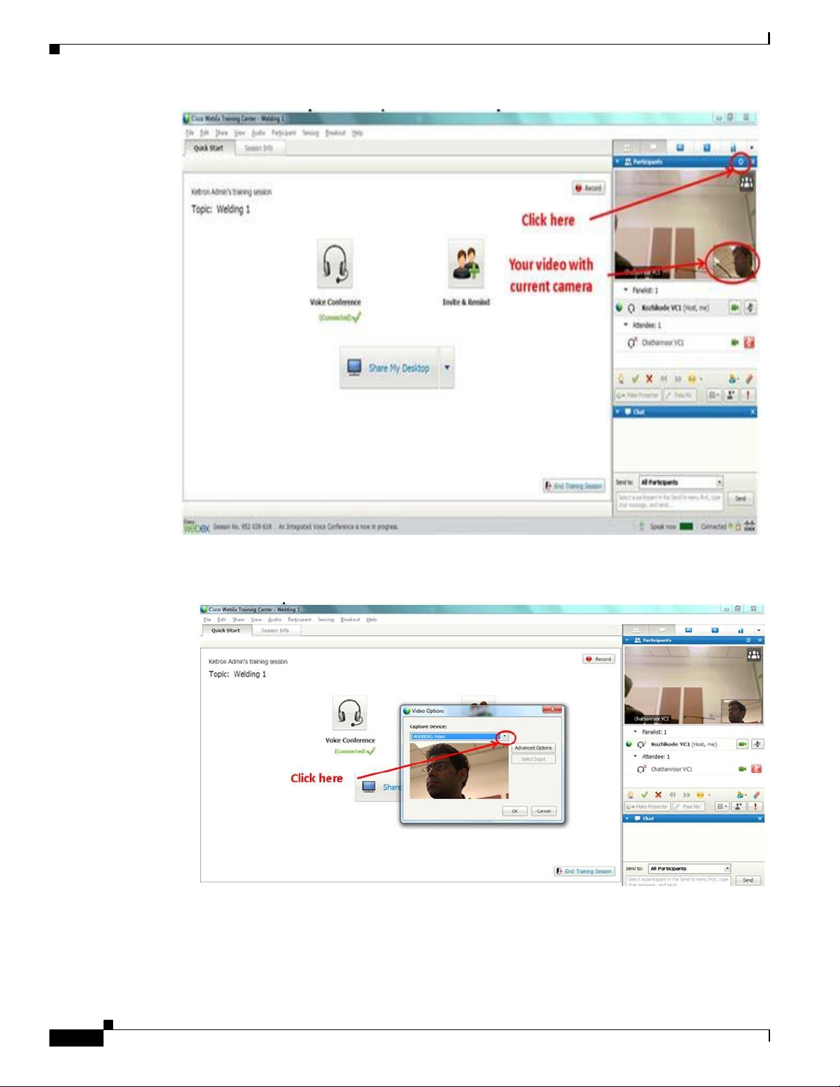
Step 3 Change the camera as shown in the figure below to test the second camera from CEED 3700. To change
of camera view, perform the following steps:
a. Click Set Video Options in the participants bar as shown in “Set Video Options” in Figure 7-4
tasks.
device.
Page 48
Chapter 7 Configuring the Live Session
7-5
R E VIEW DR AFT
—
CISC O C O NFID E N TIAL
Figure 7-4
Set Video
Options
b. A Video options dialog box appears as shown in Figure 7-5.
Figure 7-5
Video
Options
c. Click the drop-down arrow as shown in Figure 7-5 next to the present camera name.
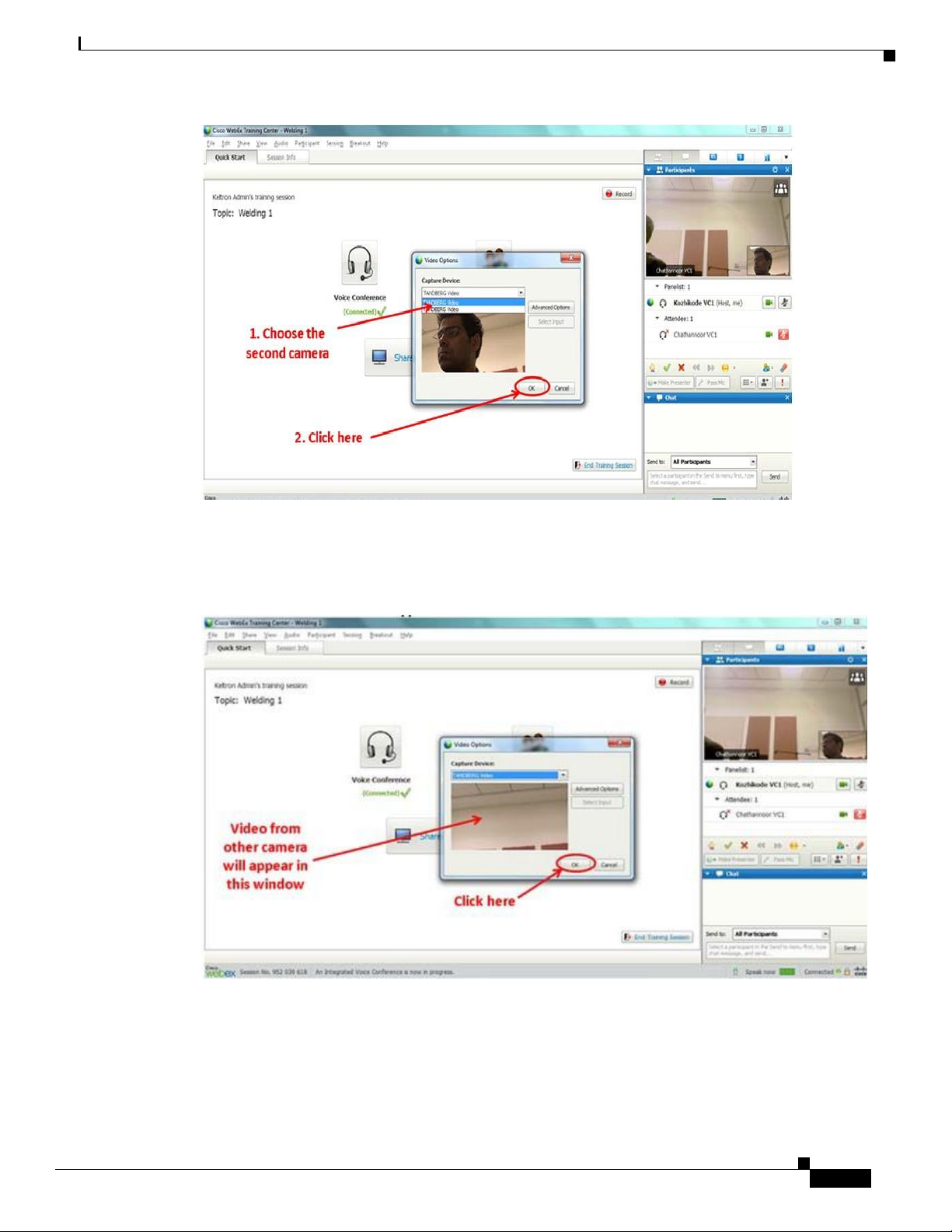
d. Select the second camera name as shown in “Capture Device” in Figure 7-6.
Page 49
Chapter 6 Configuring the Router
Powering Down/Shutting Down the CEED 3700
R E VIEW DR AFT
—
CISC O C O NFID E N TIAL
7-6
REVIEW DRAFT — CISC O C O NFIDE NTIAL
Figure 7-6
e. Click OK.
f. The video from the second camera will appear in the small window as shown in “Second Camera
Figure 7-7
Capture
Device
Trasmission” in Figure 7-7.
Second Camera
Trasmission
The attendee is set to attend the live session.
Page 50

FEDERAL COMMUNICATIONS COMMISSION I NTERFERE NCE STATEMENT
This equipment has been tested and found to comply with the limit s for a Class B
digital device, pursuant to Part 15 of the FCC Rules. These limits are designed to
provide reasonable protection against harmful interference in a residential installation.
This equipment generates, uses and can radiate radio frequency energy and, if not
installed and used in accordance with the instructions, may cause harmful
interference to radio communications. However, there is no guarantee that
interference will not occur in a particular installation. If this equipment does cause
harmful interference to radio or television reception, which can be determined by
turning the equipment of f and on, the user is encouraged to try to correct the
interference by one or more of the following measures:
-- Reorient or relocate the receiving antenna.
-- Increase the separation between the equipment and receiver.
-- Connect the equipment into an outlet on a circuit different from that to which the
receiver is connected.
-- Consult the dealer or an experienced radio/TV technician for help.
CAUTION:
Any changes or modifications not expressly approved by the p arty responsible for
compliance could void the user's authority to operate the equipment.
This device complies with part 15 of the FCC Rules. Operation is subject to the following two
conditions: (1) This device may not cause harmful interference, and (2) this device must accept any
interference received, including interference that may cause undesired operation.
FCC RF Radiation Exposure Statement:
1. This Transmitter must not be co-located or operating in conjunction with any other antenna or transmitter.
2. This equipment complies with FCC RF radiation exposure limits set forth for an uncontrolled environment.
This equipment should be installed and operated with a minimum distance of 20 centimeters between
the radiator and your body.
 Loading...