

Page 1
This document is exclusive property of Cisco Systems, Inc. Permission is granted to print and copy
this document for noncommercial distribution and exclusive use by instructors in the CCNA 2:
Routers and Routing Basics course as part of an official Cisco Networking Academy Program.
Page 2
I. Welcome
Welcome to the CCNA 2 version 3.1 Instructor Guide. Cisco Worldwide Education (WWE) has
developed this guide to provide a helpful resource for instructors. This introduction will
emphasize four themes:
• Student-centered, instructor-facilitated model
• One size does not fit all
• Hands-on, skills-based learning
• Global community of educators
Student-Centered, Instructor-Facilitated
The CCNA curriculum has not been designed as a standalone e-learning or distance-learning
course. The teaching and learning model of the Cisco Networking Academy® Program is
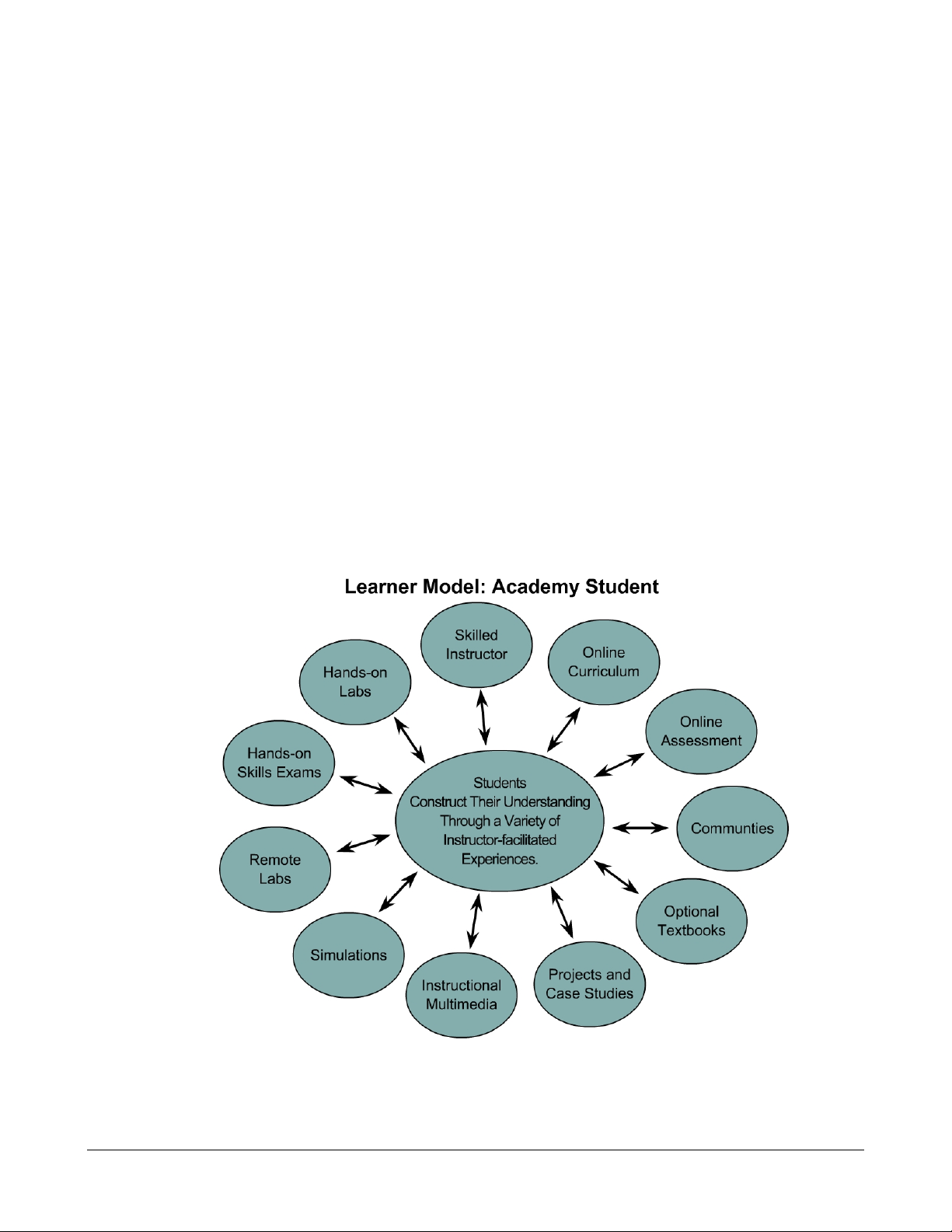
based on instructor facilitation. The Learner Model: Academy Student diagram shows the
emphasis that WWE puts on the learner. The model begins with the prior knowledge of
students. The instructor guides learning events, which are built from a variety of resources, to
help the students achieve their desired comprehension of networking.
1 - 238 CCNA 2: Routers and Routing Basics v3.1 Instructor Guide – Welcome Copyright © 2004, Cisco Systems, Inc.
Page 3

One Size Does Not Fit All
The Cisco Networking Academy Program serves hundreds of thousands of students in almost
150 countries. Students range from early teens to mature adults and from advanced middle
school students to undergraduate engineering students.
One curriculum cannot fit the needs of all students. WWE relies on local instructors to make
the program work and to help their students achieve the learning goals of the program. There
are three fixed reference points for each program that provide flexibility for the instructors:
• The mission of WWE to educate and train
• The requirements of the CCNA certification exam
• The hands-on skills that help prepare students for the industry and further
education
The WWE policy allows instructors to "add anything, but subtract nothing" from the curriculum.
WWE supports in-class differentiation, which is used to provide additional support for students
who need it and additional challenges for advanced students. WWE also allows instructors to
decide how much time to spend on various topics. Some topics can be skimmed, while others
may need to be emphasized for different audiences. The local instructor must decide how to
balance the need for hands-on labs with the realities of the local student-to-equipment ratio
and time schedule. This Guide can be used to facilitate the preparation of lesson plans and
presentations. Instructors are encouraged to research and use external sources to develop
additional labs and exercises.
Core TIs have been highlighted for emphasis to assist the instructor in course and lesson
planning. These are not the only TIs that need to be taught. Many core TIs will only make
sense after the preceding TIs have been reviewed. It may be useful to have a map of the core
TIs, which contain the most important knowledge and skills for success in the CCNA program.
The assessment process is multifaceted and flexible. A wide variety of assessment options
exist to provide feedback to students and document their learning. The Academy assessment
model is a blend of formative and summative assessments that include online and hands-on,
skills-based exams.
Hands-On, Skills-Based
The core of the CCNA 2 experience is the sequence of hands-on labs. Labs are designated as
either essential or optional. Essential labs include information that is fundamental to the CCNA
Academy student experience. This information will help students prepare for the certification
exam, succeed in job situations, and develop their cognitive abilities. In CCNA 2, students will
learn about the following elements of basic router configuration:
• Hostnames, banners, and passwords
• Interface configuration
• IOS file system
• Static routes and dynamic routing (RIP version 1 and IGRP)
2 - 238 CCNA 2 Routers and Routing Basics v3.1 Instructor Guide – Welcome Copyright © 2004, Cisco Systems, Inc.
Page 4

• Standard and extended access-list configuration and placement
• show, debug, ping, trace, and telnet commands to verify and troubleshoot
Global Community
WWE instructors are members of a global community of educators. There are over 10,000
instructors that teach the same eight CCNA and CCNP courses in the program. Instructors
should take advantage of the diversity and skills of this community through their Regional
Academies, Cisco Academy Training Centers (CATCs), the Cisco Academy Connection
(CAC), or through other forums. WWE is committed to the improvement of the curriculum,
assessment model, and instructional resources such as this guide. Please submit any
feedback through CAC. Check CAC for new releases of instructional materials.
Guide Overview:
Section II provides a scope and sequence overview of the course. Section III summarizes the
most important learning objectives, target indicators, and labs, and offers teaching suggestions
and background information. Section IV provides a case study related to network design,
implementation, and troubleshooting. Instructors can also devise their own case studies.
Section V includes four appendices:
• Cisco online tools and utilities
• CCNA assessment guidelines
• Evidence-centered design of assessment tasks in the Networking Academy
program
• Instructional best practices
3 - 238 CCNA 2 Routers and Routing Basics v3.1 Instructor Guide – Welcome Copyright © 2004, Cisco Systems, Inc.
Page 5

II. Course Overview
Target Audience
The target audience is anyone who desires a practical and technical introduction to the field of
networking. This includes high school, community college, and lifelong-learning students who
are interested in careers as network technicians, network engineers, network administrators,
and network help-desk staff.
Prerequisites
The successful completion of this course requires the following:
• Reading age level of 13 or higher
• Successful completion of CCNA 1
The following prerequisites are beneficial, but not required:
• Prior experience with computer hardware and command line interfaces
• Background in computer programming
Course Description
CCNA 2: Routers and Routing Basics is the second of four CCNA courses that lead to the
Cisco Certified Network Associate (CCNA) designation. CCNA 2 focuses on initial router
configuration, Cisco IOS Software management, routing protocol configuration, TCP/IP, and
access control lists (ACLs). Students will learn how to configure a router, manage Cisco IOS
software, configure routing protocols on routers, and set access lists to control access to
routers.
Course Objectives
The CCNA certification indicates knowledge of networking for the small office, home office
(SOHO) market and the ability to work in small businesses or organizations that use networks
with fewer than 100 nodes. A CCNA-certified individual can perform the following tasks:
• Install and configure Cisco switches and routers in multiprotocol internetworks that
use LAN and WAN interfaces
• Provide Level 1 troubleshooting service
• Improve network performance and security
• Perform entry-level tasks in the planning, design, installation, operation, and
troubleshooting of Ethernet and TCP/IP Networks
4 - 238 CCNA 2: Routers and Routing Basics v3.1 Instructor Guide – Course Overview Copyright © 2004, Cisco Systems, Inc.
Page 6

Students must successfully complete the CCNA 2 course before they can achieve CCNA
certification.
Upon completion of this course, students will be able to perform tasks related to the following:
• Routers and their roles in WANs
• Cisco IOS Software Management
• Router configuration
• Router file management
• RIP and IGRP routing protocols
• TCP/IP error and control messages
• Router troubleshooting
• Intermediate TCP
• Access control lists
Lab Requirements
Please refer to the CCNA equipment bundle spreadsheets on the Cisco Academy Connection.
Certification Alignment
The curriculum is aligned with the following Cisco Internet Learning Solution Group (ILSG)
courses:
• CCNA (Cisco Certified Network Associate)
• INTRO (Introduction to Cisco Networking Technologies)
The Course 2 claims state that students will be able to complete the following tasks:
• Identify the key characteristics of common wide-area network (WAN)
configurations and technologies, and differentiate between these and common
LAN technologies
• Describe the role of a router in a WAN
• Describe the purpose and operations of the router Internet Operating System
(IOS)
• Establish communication between a terminal device and the router IOS, and use
IOS for system analysis, configuration, and repair
• Identify the major internal and external components of a router, and describe the
associated functionality
5 - 238 CCNA 2: Routers and Routing Basics v3.1 Instructor Guide – Course Overview Copyright © 2004, Cisco Systems, Inc.
Page 7

• Connect router Fast Ethernet, serial WAN, and console ports
• Perform, save, and test an initial configuration on a router
• Configure additional administrative functionality on a router
• Use embedded data-link layer functionality to perform network neighbor discovery
and analysis from the router console
• Use embedded Layer 3 through Layer 7 protocols to establish, test, suspend, or
disconnect connectivity to remote devices from the router console
• Identify the stages of the router boot-up sequence and show how the configuration
register and boot system commands modify that sequence
• Manage system image and device configuration files
• Describe the operation of the Internet Control Message Protocol (ICMP) and
identify the reasons, types, and format of associated error and control messages
• Identify, configure, and verify the use of static and default routes
• Evaluate the characteristics of routing protocols
• Identify, analyze, and show how to rectify inherent problems associated with
distance vector routing protocols
• Configure, verify, analyze, and troubleshoot simple distance vector routing
protocols
• Use commands incorporated within IOS to analyze and rectify network problems
• Describe the operation of the major transport layer protocols and the interaction
and carriage of application layer data
• Identify the application of packet control through the use of various access control
lists
• Analyze, configure, implement, verify, and rectify access control lists within a
router configuration
Course Overview
The course has been designed for 70 contact hours. Approximately 35 hours will be
designated to lab activities and 35 hours will be designated to curriculum content. A case
study on routing is required. The format and timing should be determined by the Local
Academy.
6 - 238 CCNA 2: Routers and Routing Basics v3.1 Instructor Guide – Course Overview Copyright © 2004, Cisco Systems, Inc.
Page 8

The following changes have taken place since CCNA version 2.x:
• More emphasis on router configuration early in semester
• More efficient presentation and practice of IOS
• IGRP moved from CCNA 3 to CCNA 2
• Access lists moved from CCNA 3 to CCNA 2
• Revisions to TCP/IP coverage
• More focus on routing tables
• Case study is required with format and timing determined by the Local Academy
• More interactive flash activities
• Sequence of over 40 e-Labs
• Lab focus on two-router labs
7 - 238 CCNA 2: Routers and Routing Basics v3.1 Instructor Guide – Course Overview Copyright © 2004, Cisco Systems, Inc.
Page 9

III. Teaching Guide for Each TI
Nomenclature
The CCNA curriculum uses the following hierarchy:
• Course
• Module
• Learning objective (LO)
• Target indicator (TI)
For example, 3.2.5 references Module 3, LO 2, and TI 5. The following terms are commonly
used to describe the curriculum, instructional materials, and assessments in WWE and Cisco
documentation:
• Certification-level claims
High-level statements about what a CCNA-certified person should know and be
able to do. These claims are measured through certification exams.
• Course
A subset of a curriculum which is a collection of chapters to be offered as a
scheduled course
• Course-level claims
Medium-level statements about what a person who completes the CCNA 2 course
should know and be able to do.
• Core TI
The TIs that apply most directly to the claims and learning objectives. Instructors
should not skip over these TIs or move through them quickly.
• Curriculum
A predefined or dynamic path of learning events with an end goal such as
certification or the acquisition of required job skills and knowledge.
• Hands-on skills
There is some overlap between hands-on skills and claims. These statements
emphasize hands-on, lab-based learning.
.
8 - 238 CCNA 2: Routers and Routing Basics v3.1 Instructor Guide – Teaching Guide: TI by TI Copyright © 2004, Cisco Systems, Inc.
Page 10

• Module
Logical groupings that comprise a course. Modules contain multiple lessons or
LOs. Modules are also referred to as chapters.
• Learning objective (LO)
A statement that establishes a measurable behavioral outcome. LOs are used to
organize content and to indicate how the acquisition of skills and knowledge will be
measured. LOs are also referred to as terminal objectives or RLOs.
• Lesson
A set of TIs, or enabling objectives, that are grouped together and presented in a
coherent format to meet an LO, or terminal objective. Lessons emphasize the role
of the instructor. Learning objectives emphasize the role of the students.
• Module caution
Suggestions related to areas where difficulties may be encountered. These are
especially important for syllabus development, lesson planning, and pacing.
• Optional lab
A lab that is for practice, enrichment, or differentiation.
• Essential lab
A lab that is fundamental to the course.
• Reusable Learning Object (RLO)
This is a Cisco Instructional Design term. RLOs typically consist of five to nine
RIOs. In this guide, RLOs are equivalent to lessons or learning objectives.
• Reusable Information Object (RIO)
This is a Cisco Instructional Design term. In this guide, RIOs are equivalent to
target indicators.
• Target indicator (TI)
TIs are also referred to as enabling objectives or RIOs. TIs typically consist of a
text frame with graphics and several media content items.
9 - 238 CCNA 2: Routers and Routing Basics v3.1 Instructor Guide – Teaching Guide: TI by TI Copyright © 2004, Cisco Systems, Inc.
Page 11

Module 1: WANs and Routers
Overview
When teaching Module 1, show the students how router configuration relates to the Internet,
which is a global internetwork made possible by routers. Students will learn the difference
between WANs and LANs, and will identify WAN connections, encapsulations, and protocols.
Module 1 Caution
WANs will be taught in detail in CCNA 4. In CCNA 2, it is important to teach students the
fundamental basics of WANs and roles that routers play in the WAN connection. Inform the
students that the serial interfaces will be used to simulate the DCE to DTE WAN connection.
Do not spend too much time on this module.
Students who complete this module should be able to:
• Identify organizations responsible for WAN standards
• Explain the difference between WANs and LANs and the types of addresses they
use
• Describe the role of a router in a WAN
• Identify internal components of a router and describe their functions
• Describe the physical characteristics of a router
• Identify common ports on a router
• Connect Ethernet, serial WAN, and console ports
10 - 238 CCNA 2: Routers and Routing Basics v3.1 Instructor Guide – Module 1 Copyright © 2004, Cisco Systems, Inc.
Page 12

1.1 WANs
Essential labs: None
Optional labs: None
Core TIs: All
Optional TIs: none
Course-level claim: Students can identify the important characteristics of common WAN
configurations and technologies, differentiate between these and common LAN technologies,
and describe the role of a router in a WAN.
Certification-level claim: Students can evaluate the important characteristics of WANs and
implement simple WAN protocols.
Hands-on skills: none
1.1.1 Introduction to WANs
WANs differ from LANs in several ways:
• LANs connect workstations, peripherals, terminals, and other devices in a single
building or several buildings that are located next to each other, and WANs
connect large geographic areas.
• LANs connect devices and WANs connect data connections across a broad
geographic area.
WANs operate at the physical and data-link layers of the OSI model. Devices used in a WAN
are routers, switches, modems, and communication servers. The following topics are relevant
to this TI:
• Discuss the various carriers and devices available for WAN connections.
• Show students what routers in a WAN look like.
• Explain what routers do.
Figure 3 is an important figure to review. Best instructional practices for this TI include online
study sessions with study guides, group work, and mini-lectures. This TI provides essential
background information for the CCNA exam.
1.1.2 Introduction to routers in a WAN
Routers and computers have four basic common components:
• CPU
• Bus
11 - 238 CCNA 2: Routers and Routing Basics v3.1 Instructor Guide – Module 1 Copyright © 2004, Cisco Systems, Inc.
Page 13

• Memory
• Interfaces
However, the main purpose of a router is to route, not to compute. The main components of
the router are as follows:
• RAM
• NVRAM
• Flash
• ROM
• Interfaces
The following topics should be covered in this TI:
• Discuss the similarities of computers and routers such as the software they use.
• Explain the components of the router and what each component contains.
• Open a router and let the students examine the inside. Point out the main
components.
• Explain that just as a computer cannot work without an operating system and
software, a router cannot work without an operating system and configurations.
1.1.3 Router LANs and WANs
Routers function in both LANs and WANs. They are primarily used in WANs. Explain that
routers have both LAN and WAN interfaces. Students should be able to identify the
differences. The two main functions of a router are to select the best path and to forward
packets to the correct outgoing interfaces.
Networking models are useful because they facilitate modularity, flexibility, and adaptability.
Like the OSI model, the three-layer design model is an abstract picture of a network. Models
may be difficult to comprehend because the exact composition of each layer varies from
network to network.
Explain that each layer of a three-layer design model may include a router, a switch, a link, or
some combination of these. Some networks may combine the function of two layers into a
single device or may omit a layer entirely. The three-layer design model consists of the
following:
• The core layer forwards packets as quickly as possible.
• The distribution layer provides a boundary by using filters to limit what gets to the
core.
• The access layer feeds traffic into the network and controls entry into the network.
12 - 238 CCNA 2: Routers and Routing Basics v3.1 Instructor Guide – Module 1 Copyright © 2004, Cisco Systems, Inc.
Page 14

1.1.4 Role of Routers in a WAN
There are several encapsulations associated with serial lines:
• HDLC
• Frame Relay
• PPP
• SDLC
• SLIP
• LAPB
Some of the most common WAN technologies are as follows:
• POTS
• ISDN
• X.25
• Frame Relay
• ATM
• T1, T3, E1, and E3
• DSL
• SONET
Ask students to briefly explain each of the WAN technologies and discuss the differences
between technologies and encapsulations. They will be covered in detail in CCNA 4.
It is important to encourage student interest and enthusiasm in this TI. The world of WAN
technologies is briefly introduced. Many students will be familiar with one or more of the
technologies used. Many of these topics will be covered in CCNA 4 and students should be
encouraged to do additional research on one of these technologies and present it to the class.
1.1.5 Academy approach to hands-on labs
In the Networking Academy lab, all the networks are connected with a serial or Ethernet cable.
This allows the students to see and touch all of the equipment. In a real network, the routers
would not be in one physical location. In the Networking Academy lab, the serial cables are
connected back-to-back. However, in the real world the cables would be connected through a
CSU or DCE device.
Discuss the differences between real networking environments and the router lab setup. Help
the students visualize the components between the V.35 connectors. If they can understand
this picture, then they will realize that they are working with a complete WAN minus the carrier
services.
13 - 238 CCNA 2: Routers and Routing Basics v3.1 Instructor Guide – Module 1 Copyright © 2004, Cisco Systems, Inc.
Page 15

Each student should build a complete topology and then take it apart and let the next student
do the lab. These labs are a review of the cabling labs in CCNA 1. This may be one of the last
opportunities students have to cable a network, so do not miss this opportunity to make sure
students complete the CCNA 2 Lab setup. This is a good place to introduce troubleshooting
and the Layer 1 issues that occur in CCNA 2. It is also a fairly simple and fun activity.
1.2 Routers
Essential Labs: 1.2.5, 1.2.6, and 1.2.7
Optional Labs: None
Core TIs: All
Optional TIs: none
Course- Level Claim: Students can properly connect router Fast Ethernet, Serial WAN, and
console ports.
Certification-Level Claim: Students can describe the components of network devices. They
can also identify the major internal and external components of a router and describe the
associated functionality.
Hands-on skills: none
1.2.1 Introduction to WANs
This section overviews the physical aspect of a router. The physical layer is always studied
first in networking topics. The student will be able to identify internal components of the router
and describe their functions, describe the physical characteristics of the router, identify
common ports on a router, and properly connect FastEthernet, Serial WAN, and console ports.
The components in a router are essentially the same as those in a computer. In fact, a router
can be thought of as a computer designed for the special purpose of routing. While the exact
architecture of the router varies in different router series, this section will introduce the major
internal components. The figures show the internal components of some of the Cisco router
models.
Ask students the following questions:
• What are the common components of a router?
• What is NVRAM used for?
1.2.2 Router physical characteristics
It is not necessary to know the location of the physical components inside the router to
understand how to use the router. The exact components used and their locations vary in
different router models.
14 - 238 CCNA 2: Routers and Routing Basics v3.1 Instructor Guide – Module 1 Copyright © 2004, Cisco Systems, Inc.
Page 16

Ask students the following questions:
• What are the different types of RAM used by a router?
• Can the RAM be upgraded in a router?
1.2.3 Router external connections
The three basic types of connections on a router are LAN interfaces, WAN interfaces, and
management ports. LAN interfaces allow the router segment network boundaries within a LAN
and reduce broadcast traffic within a LAN. WAN connections are provided through a service
provider which connects two or more distant site through the Internet or PSTN. The LAN and
WAN connections provide network connections through which frames are passed. The
management port provides an ASCII or text-based connection for the configuration and
troubleshooting of the router.
Ask students the following questions:
• What are the three basic types of connections on a router?
• What is the console connection used for?
1.2.4 Management port connections
The management ports are asynchronous serial ports. They are the console port and the
auxiliary port. Not all routers have an auxiliary port. These serial ports are not designed as
networking ports. To prepare for initial startup and configuration, attach an RS-232 ASCII
terminal or a computer that emulates an ACSII terminal to the system console port.
It is essential for students to understand the difference between network interfaces and nonnetwork interfaces. The instructor may need to talk about the differences extensively.
Discuss the following topics:
• The network ports use network encapsulation frames while the non-network ports
are bit and byte oriented.
• There is no addressing involved in the serial management ports.
• The serial interface for management is asynchronous and the serial WAN interface
is synchronous.
Ask students the following questions:
• Which port is preferred for troubleshooting and why?
• Do all routers have an auxiliary port?
1.2.5 Console Port Connections
The console port is a management port used to provide out-of-band access to a router. It is
used for the initial configuration of the router, monitoring, and disaster recovery procedures.
15 - 238 CCNA 2: Routers and Routing Basics v3.1 Instructor Guide – Module 1 Copyright © 2004, Cisco Systems, Inc.
Page 17

Students may not be familiar with the term out-of-band. Out-of-band refers to the fact that the
management control communications use a different path or channel than the data
communications.
Ask students the following questions:
• What type of terminal emulation must the PC or terminal support?
• What are the steps to connect the PC to a router?
1.2.6 Connecting Router LAN interfaces
In most LAN environments, an Ethernet or FastEthernet interface is used to connect the router
to the LAN. The router is a host that connects to the LAN through a hub or a switch. A straightthrough cable is used to make this connection. The correct interface must be used.
If the wrong interface is connected, the router or other networking devices may be damaged.
This is generally not true within LAN interfaces. However, if LAN interfaces are connected to
some form of WAN interface such as ISDN, damage can occur. The students should be taught
to be observant and careful whenever connections are made.
Ask students the following questions:
• What type of cable is used to connect from the router Ethernet interface to a hub
or switch?
• What type of cable is used to connect from the router Ethernet interface to a router
Ethernet interface?
1.2.7 Connecting WAN interfaces
There are many forms of WAN connections. A WAN uses many different types of technology
to make data connections across a broad geographic area. WAN services are usually leased
from service providers. The WAN connection types include leased line, circuit switched, and
packet switched.
Many of the WAN interfaces use the same physical interfaces but different pinouts and
electrical characteristics. This difference in electrical characteristics could potentially cause
damage if the wrong connections were made. Again, the students should be taught to be
observant and careful when they make any connections.
Ask students to perform the following tasks:
• List the physical layer standards that Cisco routers support.
• List the different types of WAN connections.
16 - 238 CCNA 2: Routers and Routing Basics v3.1 Instructor Guide – Module 1 Copyright © 2004, Cisco Systems, Inc.
Page 18

Module 1 Summary
Before students move on to Module 2, they must be able to cable the lab setup, identify all
external relevant ports, and identify internal router components.
Online assessment options include the end-of-module online quiz in the curriculum and the
online Module 1 exam. Consider introducing formative assessments, where the instructor
supervises the students as they work on the router setup. The use of formative assessments
can be very valuable while students work through this router-intensive and IOS-intensive
course.
Students should understand the following main points:
• WAN and LAN concepts
• Role of a router in WANs and LANs
• WAN protocols
• How to configure console connections
• The identification and description of the internal components of a router
• The physical characteristics of a router
• The common ports on a router
• How to connect router console, LAN, and WAN ports
17 - 238 CCNA 2: Routers and Routing Basics v3.1 Instructor Guide – Module 1 Copyright © 2004, Cisco Systems, Inc.
Page 19

Module 2: Introduction to Routers
Overview
Consider the prior knowledge of students when teaching Module 2. Some students may be
familiar with command-line interfaces (CLIs). Students who have only used GUIs may not
know how to use CLIs to interact with a computer. Students should experiment with CLIs to
learn how to interact with a router.
Module 2 Caution
Students need to know what the IOS is and what it does. They also need to know the
difference between the configuration file and the IOS. It is also important for students to feel
comfortable when they enter into and move around in the CLI. Do not move too quickly
through these labs. If students are uncomfortable with the CLI, they will have difficulties with
more complex labs.
Students who complete this module should be able to perform the following tasks:
• Describe the purpose of the IOS
• Describe the basic operation of the IOS
• Identify various IOS features
• Identify the methods to establish a command-line interface (CLI) session with the
router
• Move between the user command executive (EXEC) and privileged EXEC modes
• Establish a HyperTerminal session on a router
• Log into a router
• Use the help feature in the command-line interface
• Troubleshoot command errors
18 - 238 CCNA 2: Routers and Routing Basics v3.1 Instructor Guide – Module 2 Copyright © 2004, Cisco Systems, Inc.
Page 20

2.1 Operating Cisco IOS Software
Essential Labs: None
Optional Labs: None
Core TIs: All
Optional TIs: none
Course-Level Claim: Students can describe the purpose and fundamental operation of the
router IOS.
Certification-Level Claim: Students can establish communication between a terminal device
and the router IOS and use it for system analysis, configuration, and repairs.
Hands-on skills: none
2.1.1 The purpose of Cisco IOS software
In this TI, students will be introduced to the fundamentals of the Cisco Internet Operating
System (IOS). Student will learn about the show version command, which helps users gain
information about the Cisco IOS. The IOS command line interface is introduced in another
lesson, so there is no need to focus on the show command in this TI.
A router and switch cannot function without an operating system. Cisco IOS is the installed
software in all Cisco routers and Catalyst switches.
A computer needs an operating system such as Windows or UNIX. Discuss how the hardware
cannot function without this software. Make sure the students understand the role of the IOS.
2.1.2 Router user interface
Cisco IOS software uses a command-line interface (CLI) as its console environment. The CLI
is accessible through several methods:
• Console port
• Auxiliary port
• Telnet session
Students should know the difference between these methods. They should also be
comfortable with the term CLI.
2.1.3 Router user interface modes
The user EXEC mode allows a limited number of basic monitoring commands. This mode is
often referred to as a view-only mode. The privileged EXEC mode provides access to all router
commands. To enter the privileged mode from user mode the enable command must be
entered. The privileged mode is used to access other modes to configure the router.
19 - 238 CCNA 2: Routers and Routing Basics v3.1 Instructor Guide – Module 2 Copyright © 2004, Cisco Systems, Inc.
Page 21

Students should be able to identify the router prompts. The user mode prompt is Router>.
The privileged mode prompt is Router#.
2.1.4 Cisco IOS software features
Cisco IOS devices have three operating environments:
• ROM monitor
• Boot ROM
• Cisco IOS
ROM monitor is used to recover from system failures and recover a lost password. Boot ROM
is used to modify the Cisco IOS image in flash. There is a limited subset of features in this
mode. Normal operation of a router requires the full Cisco IOS image. Discuss the three
operating environments. Students should be able to identify these environments. Students
must be familiar with the IOS to control the router. Cisco technology is in the IOS, not in the
hardware.
2.1.5 Operation of Cisco IOS software
There are numerous IOS images for different Cisco device models. Each devise uses a similar
basic command structure for configuration. The configuration and troubleshooting skills
acquired on a specific device will apply to a variety of products.
The naming convention for the different Cisco IOS Releases contains three parts:
• The platform on which the image runs
• The special capabilities and feature sets supported in the image
• Where the image runs and whether it has been zipped or compressed
One of the major constraints for the use of a new IOS image is compatibility with the router
flash and RAM memory.
The students should also understand that the same IOS is used on the smallest to the largest
Cisco products. This will assure students that the skills they develop on small Cisco routers
can be applied to larger routers and switches.
Show students various naming conventions and identify the three parts of the naming
convention. For example, in cpa25-cg-1, cpa25 is the Cisco Pro 2500 Router, cg is the feature
capability such as communication server, remote-access server, or ISDN, and the 1 is the run
location or compressed status.
Explain that it is important to install and maintain various IOS versions, especially newer
versions with advanced features. Encourage the students to conduct research online at
www.cisco.com for more information on how to obtain various IOS images.
20 - 238 CCNA 2: Routers and Routing Basics v3.1 Instructor Guide – Module 2 Copyright © 2004, Cisco Systems, Inc.
Page 22

2.2 Starting a Router
Essential Labs: 2.2.1, 2.2.4, and 2.2.9
Optional Labs: None
Core TIs: All
Optional TIs: none
Course-Level Claim: Students can describe the purpose and fundamental operation of the
router IOS
Certification-Level Claim: Students can establish communication between a terminal device
and the router IOS and use it for system analysis, configuration, and repair
Hands-on skills: none
2.2.1 Initial startup of Cisco routers
This section teaches students about the startup process for a router. Students learn how to
establish a HyperTerminal session and log into a router. Students will then be introduced to
the help feature and enhanced editing commands.
When a Cisco router powers up, it performs a POST. This executes diagnostics from ROM on
all hardware modules. After the POST, the following events occur as the router initializes:
• Bootstrap is loaded from ROM.
• IOS is loaded from flash, TFTP, or ROM.
• Config is loaded from NVRAM or TFTP into setup mode.
This section teaches students how to check the configuration during the boot process. Setup
mode is intended to quickly install a router with minimal configuration. Discuss the initial
startup of routers and explain why the IOS and configuration files can be loaded from several
places.
2.2.2 Router LED indicators
Router LED indicators indicate the status of a router. If an interface is extremely busy, its LED
will be on all the time. The green LED will be on after the router card initializes correctly.
Have the students view the LED indicators on the routers in the lab setup. Show them LEDs
that work correctly and explain what they are. Make sure the students understand that the port
status and link LEDs are the prime indicators of the physical layer status.
2.2.3 The initial router bootup
Bootup messages displayed by a router include messages such as “NVRAM invalid, possibly
due to write erase”, which indicates that the router has not been configured or the backup
configuration has been erased.
21 - 238 CCNA 2: Routers and Routing Basics v3.1 Instructor Guide – Module 2 Copyright © 2004, Cisco Systems, Inc.
Page 23

If a router does not boot up correctly, issue the show version command to examine the
configuration register to see if it is booting.
Remind the students that the router is a special purpose computer. It has a boot sequence that
is similar to a standard computer. The router must load the IOS from one of several sources.
The router must also obtain a configuration file. If a configuration file is not available, the router
will enter setup mode, which prompts the user for a basic router configuration. Make sure the
students understand what the router needs as basic configuration information. This provides a
lot of information about how the router works. It is very important for students to understand
the difference between the IOS and the configuration file.
2.2.4 Establish a console session
To establish a HyperTerminal Console session, students should complete the following steps:
1. Connect the terminal with an RJ-45-to-RJ-45 rollover cable and an RJ-45-to-DB-9 or
RJ-45-to-DB-25 adapter
2. Configure the terminal or PC terminal emulation software for 9600 baud, 8 data bits, no
parity, 1 stop bit, and no flow control
Instruct the students to connect the cables from the router to the PC and to connect with the
HyperTerminal program. To configure a router, a connection must be established between the
PC and a router. Make sure students understand that this is how routers need to be configured
initially, but it is not the only way to configure a router.
2.2.5 Router login
There are two levels of access to commands in a router:
• User EXEC mode
• Privileged EXEC mode
The user EXEC mode is a view-only mode. Enter privileged EXEC mode with the enable
command from the User prompt. Other modes can be accessed from privileged mode to
configure a router. The students should have a lot of practice with hands-on activities in the lab
setup. It is important for students to understand the various modes to be able to accurately
configure a router. It is not necessary to memorize all commands. Students must understand
each mode so they can make the configurations from the correct locations.
2.2.6 Keyboard help in the router CLI
At the user mode prompt, a question mark (?) should be typed to display a list of commands
available in the router. From user mode, the enable command will switch the router into the
privileged mode. If a question mark (?) is entered from the privileged mode prompt, many
more commands are listed as available commands to use in the router. Students should briefly
review the types of commands in each mode. There is no need to memorize all of the
commands.
The context-sensitive help is one of the most useful features of the IOS. Teach the student
that the question mark (?) is extremely helpful in the router.
22 - 238 CCNA 2: Routers and Routing Basics v3.1 Instructor Guide – Module 2 Copyright © 2004, Cisco Systems, Inc.
Page 24

To demonstrate the help feature, instruct students to set the clock without telling them which
commands to use. The question mark (?) will guide students through the process.
2.2.7 Enhanced editing commands
Enhanced editing commands are on by default. To disable enhanced editing mode, the
terminal no editing command can be used at the privileged mode prompt.
The editing command set provides a horizontal scrolling feature for commands that extend
beyond a single line. When the cursor reaches the right margin, the command line shifts ten
spaces to the left. The first ten characters of the line cannot be seen, but a user can scroll
back to check the syntax. It is represented by a dollar sign ($).
Some of the editing commands are as follows:
• Ctrl-A moves to the beginning of the command line.
• Ctrl-B moves back one character.
• Ctrl-E moves to the end of the command line.
• Ctrl-F moves forward one character.
• Ctrl-Z moves back out of configuration mode.
• Esc and then B moves back one word.
• Esc and then F moves forward one word.
The syntax of IOS commands can be complex. Keyboard editing features can be used to
correct text that has been entered. When a router is being configured, repetitive command
statements, typing errors that need to be fixed, and commands that need to be reused may be
encountered. Questions about the Ctrl key and Esc key sequences will probably appear on
the CCNA exam.
2.2.8 Router command history
The user interface provides a history of commands that have been entered. This feature can
be used to recall long or complex commands. The command history feature can be used to
complete the following tasks:
• Set the command history buffer size
• Recall commands
• Disable the command history feature
By default, the command history records ten command lines in the history buffer. To recall
commands, press Ctrl-P or the Up Arrow key to recall repeated commands. Press Ctrl-N or
the Down Arrow key to recall more recent commands in the history. The Ctrl-P and Ctrl-N
features are also likely to be tested on the CCNA exam.
23 - 238 CCNA 2: Routers and Routing Basics v3.1 Instructor Guide – Module 2 Copyright © 2004, Cisco Systems, Inc.
Page 25

The syntax of IOS commands can be complex. The feature used to recall commands can help
students save time when they program or troubleshoot a router.
2.2.9 Troubleshooting command line errors
This troubleshooting lab allows students to log into the router and access various modes.
Demonstrate the use of the question mark (?) as a helpful tool for students who do not know
which command to enter.
Also demonstrate the use of the history command as a helpful tool for students to
troubleshoot problems without retyping repeated commands.
2.2.10 The show version command
The show version command displays information about the Cisco IOS software version.
This information includes the system image file name and the location from which it was
booted. It also contains the configuration register and the boot-field setting. Explain that an
important aspect of router and IOS maintenance is to know exactly which version of the IOS is
being used.
Cisco has numerous major and minor IOS releases. There are many different versions and
different features to meet the requirements of a network. Students should know that the show
version command shows much more than just the version of the IOS. This is an important
command. Explain to students is that this is the only command that can be used to examine
the configuration register.
24 - 238 CCNA 2: Routers and Routing Basics v3.1 Instructor Guide – Module 2 Copyright © 2004, Cisco Systems, Inc.
Page 26

Module 2 Summary
Before students move on to Module 3, they must be able to interact with the router through a
HyperTerminal session and the CLI.
Online assessment options include the end-of-module online quiz in the curriculum and the
online Module 2 exam. Make sure students know how to access the command-line prompt.
Formative assessments related to lab work are relevant to Module 2.
Students should understand the following main points:
• Understand the basic operation of IOS
• Identify various IOS features
• Identify methods to establish a CLI session with the router
• Use HyperTerminal to establish a CLI session
• Log into the router
• Use the help feature in the command line interface
• Use the enhanced editing commands
• Use the command history
• Troubleshoot command line errors
• Use the show version command
25 - 238 CCNA 2: Routers and Routing Basics v3.1 Instructor Guide – Module 2 Copyright © 2004, Cisco Systems, Inc.
Page 27

Module 3: Configuring a Router
Overview
When teaching Module 3, emphasize the empowerment that students will gain from the ability
to configure routers and the importance of familiarity with the IOS through extensive practice.
There are many tools available to teach IOS:
• The curriculum text and graphics are used to introduce command syntax and
context.
• The online command references are integrated.
• CiscoPedia is the IOS command reference in the form of a Windows help file. All
CCNA and CCNP commands are included.
• Integrated e-Labs provide guided practice of command syntax.
• Standalone e-SIMs provide more open-ended practice of CCNA 2-level router
configuration.
• Hands-on labs are integrated PDF files that should be the core of the learning
experience.
Module 3 Caution
Spend a lot of time on this module. Students have wanted to program routers since the first
day of CCNA 1. This module presents the core skills that the students will use to build all
Cisco device configurations. From this point in the CCNA 2 curriculum through the end of the
CCNA 4 curriculum, students may be deprived of the opportunity to learn about the IOS if the
student-to-equipment ratio is high. Only the local instructor can decide what mix of lab
equipment, group work, creative rotations, lab access, remote access through NetLabs or
other solutions, e-Labs, e-SIM, CiscoPedia, and other tools can be used to give students
adequate opportunities to learn IOS.
After completing this module, students should be able to perform the following tasks:
• Name a router
• Set passwords
• Examine show commands
• Configure a serial interface
• Configure an Ethernet interface
• Make changes to a router
• Save changes to a router
26 - 238 CCNA 2: Routers and Routing Basics v3.1 Instructor Guide – Module 3 Copyright © 2004, Cisco Systems, Inc.
Page 28

• Configure an interface description
• Configure a message-of-the-day banner
• Configure host tables
• Understand the importance of backups and documentation
27 - 238 CCNA 2: Routers and Routing Basics v3.1 Instructor Guide – Module 3 Copyright © 2004, Cisco Systems, Inc.
Page 29

3.1 Configure a Router
Essential Labs: 3.1.2, 3.1.3, 3.1.4, 3.1.5, 3.1.6, and 3.1.7
Optional Labs: None
Core TIs: All
Optional TIs: none
Course-Level Claim: Students can perform, save, and test an initial configuration on a router.
Certification Level Claim: Students can perform an initial configuration on a router.
Hands-on skills: none
3.1.1 CLI command modes
The students need to understand that the router does not know what routing to do until it is
configured. This section will help students begin the configuration of a router.
To gain access to a router, a login is required. After login, there is a choice of modes. The
modes interpret the commands that are typed and perform the operations. There are two
EXEC modes:
• User EXEC mode
• Privileged EXEC mode
The first configuration mode is referred to as global configuration mode or global config. The
following configuration modes are available in global configuration mode:
• Interface
• Subinterface
• Controller
• Map-list
• Map-class
• Line
• Router
Global configuration commands are used in a router to apply configuration statements that
affect the entire system. Use the privileged EXEC command configure terminal to enter
global configuration mode.
Explain that Cisco IOS is modal. Emphasize that in the CLI that there are different modes to
accomplish different tasks. There are several advantages to this. One is that the commands
are generally shorter because the object of the mode, i.e., the interface, or routing protocol, to
28 - 238 CCNA 2: Routers and Routing Basics v3.1 Instructor Guide – Module 3 Copyright © 2004, Cisco Systems, Inc.
Page 30

be changed does not need to be specified in the command. Another advantage is that only the
parameters, or objects of the mode, i.e., the interface, or routing protocol, can be modified by
the command. This helps prevent accidental configuration of the wrong object. There are
shortcuts to show students at a later time:
• config t for configure terminal
• int fa0/0 for interface fastethernet 0/0
Students commonly enter the correct command at the incorrect prompt. If the students are
unable to enter a command, check the mode. The prompt will be either Router(config)# or
Router(config-if)#.
Ask students the following questions:
• Which mode is the user in when first logging into the router?
• What mode is the user in after entering the enable command?
3.1.2 Configuring a router name
One of the first basic configuration tasks is to name a router. This task helps with network
management and uniquely identifies each router within a network. Use global configuration
mode to name a router. The name of a router is called the hostname and will be displayed as
the system prompt. If a router is not named, then the system default will be “Router”.
Students need to understand that the name is an important part of the configuration process.
Much of the configuration and troubleshooting will be performed remotely. Users will telnet into
different routers. For practice, ask students to name the routers. When instructors are asked to
help troubleshoot a lab, they can easily identify the different routers. The router name at the
prompt confirms the student has completed this task. Students should also understand that
names should be chosen to represent a location or a function. In many organizations, there
are naming conventions to be followed.
Ask students the following questions:
• What is the default name of the router?
• In which mode can the user name the router?
• What is the command to name a router?
3.1.3 Configuring router passwords
Passwords can be used to secure a router and restrict access. Passwords can be established
for virtual terminal lines and the console line. The privileged EXEC mode may also have a
password. From global configuration mode use the enable password command to restrict
access to the privileged mode. The line configuration mode can be used to establish a login
password on the console terminal. Use the command line vty 0 4 to establish a login
password on incoming Telnet sessions.
29 - 238 CCNA 2: Routers and Routing Basics v3.1 Instructor Guide – Module 3 Copyright © 2004, Cisco Systems, Inc.
Page 31

Discuss the differences between the various passwords. Students need to understand when
each password is used. If students ask if user ids and passwords can be used instead of just
passwords, the answer is that they can, but that is beyond the scope of this course.
Ask students the following questions:
• What is the command to set the enable password?
• What is the command to set the telnet password?
• What is the command to set the console password?
3.1.4 Examining the show commands
There are many show commands, which are used to examine the contents of files in the router
and for troubleshooting. From each mode in the router, the show ? command can be used to
see all the available options. Some of the show command options are as follows:
• show interfaces
• show controllers serial
• show clock
• show hosts
• show users
• show history
• show flash
• show version
• show ARP
• show protocol
• show startup-configuration
• show running-configuration
Students may want to use the show running-config command as their primary
troubleshooting tool. This is not a good habit. It is probably the quickest way to find problems
in the simple configurations used in this course. However, that is not true in most situations.
Students should learn to use the show running-config command to confirm suspected
problems. Some CLI shortcuts to show students in the future are as follows:
• sh int fa0/0 for show interface fastethernet 0/0
• sh run for show running-configuration
• sh run int fa0/0 for show running-configuration fastethernet 0/0
30 - 238 CCNA 2: Routers and Routing Basics v3.1 Instructor Guide – Module 3 Copyright © 2004, Cisco Systems, Inc.
Page 32

Ask students the following questions:
• Which command will show the configuration file in NVRAM?
• Which command will show the configuration file in RAM?
3.1.5 Configuring a serial interface
A serial interface can be configured from the console or through a virtual terminal line. By
default, Cisco routers are DTE devices but they can be configured as DCE devices. To
configure a serial interface follow these steps:
1. Enter global configuration mode.
2. Enter interface mode.
3. Specify the interface address and subnet mask.
4. Set the DCE clock rate. Skip this step on DTE.
5. Turn on the interface.
There are two important items in this TI.
The first item is that setting a clock rate is not a normal configuration item. It is only done to
simulate a WAN. The clock is normally provided by the DCE equipment such as a CSU. The
curriculum shows the command entered as clock rate, but on some Cisco routers the
command can be entered as clockrate. Both will result in the same running configuration.
The second item is that interfaces are shutdown by default and must be enabled with the no
shutdown command. The shutdown command will turn off an interface. Instruct students to
check for interfaces that are shutdown when troubleshooting the student labs. This can be
checked by typing show interface serial 0/0 or show run int serial 0/0 for the
interface serial 0/0.
Ask students the following questions:
• What command turns on an interface?
• What command turns off an interface?
• What command is entered on an interface at the DCE end of the cable?
3.1.6 Making configuration changes
To verify changes, use the show running-config command. This command will display
the current configuration. If the intended variables are not displayed, the environment can be
corrected in the following ways:
• Issue the no form of a configuration command.
• Restart the system and reload the original configuration file from NVRAM.
31 - 238 CCNA 2: Routers and Routing Basics v3.1 Instructor Guide – Module 3 Copyright © 2004, Cisco Systems, Inc.
Page 33

• Remove the startup configuration file with the erase startup-config
command.
• Restart the router and enter setup mode.
To save the configuration variables to the startup configuration file in NVRAM, enter the
following command at the privileged EXEC prompt:
Router#copy running-config startup-config
Students must understand that any changes that are made to the configuration will occur
immediately. These changes are made to the running configuration. Students must also
realize that configuration changes need to be saved to the startup configuration. If they are
not, then they will be lost when the router is restarted. Students should shut down interfaces
during configuration and enable the interface after the configuration changes are completed.
Ask students the following questions:
• Which command will erase the configuration file in NVRAM?
• Which command will erase the configuration file in RAM?
• Which command will copy the RAM to NVRAM?
• Which command will copy the NRAM to RAM?
3.1.7 Configuring an Ethernet interface
An Ethernet interface can be configured from the console or a virtual terminal line. By default,
interfaces are disabled. Use the no shutdown command to enable an interface. Use the
shutdown command to turn off an interface if it needs to be disabled for maintenance or
troubleshooting. The following command is used to configure interface serial 0/0. The interface
will change to up. Both ends of the serial cable need to be configured for the interface to stay
in an up state:
rt1(config)#interface serial 0/0
rt1(config-if)#ip address 192.168.0.1 255.255.255.0
rt1(config-if)#no shutdown
00:20:46: %LINK-3-UPDOWN: Interface Serial0/0, changed state to
up
00:20:47: %LINEPROTO-5-UPDOWN: Line protocol on Interface
Serial0/0, changed state to up
rt1(config-if)#
32 - 238 CCNA 2: Routers and Routing Basics v3.1 Instructor Guide – Module 3 Copyright © 2004, Cisco Systems, Inc.
Page 34

3.2 Finishing the Configuration
Essential Labs: 3.2.3, 3.2.5, 3.2.7, and 3.2.9
Optional Labs: None
Core TIs: All
Optional TIs: none
Course-Level Claim: Students can configure additional administrative functionality on a router
Certification-Level Claim: Students can configure a router for additional administrative
functionality.
Hands-on skills: none
3.2.1 Importance of configuration standards
This section introduces the importance of configuration standards. The following topics are
covered:
• Configuration of interface descriptions
• Message-of-the day banners
• Configuration of host tables
• Backup configuration documentation
In many organizations, standards are either treated very seriously or there are no standards. It
is important to develop standards for configuration files within an organization. These can be
used to control of the number of configuration files that must be maintained, how the files are
stored, and where the files are stored.
In organizations where standards are treated seriously, students need to understand that it is
very important for the standards to be followed. In organizations where there are no standards,
students can introduce standards to add value to the organization.
Students need to understand why standards are important and begin to apply them in the lab.
Encourage students to create and use standards. Remember to simulate real-world
environments in the classroom and lab.
A centralized support standard is necessary to manage a network. Configuration, security,
performance, and other issues must be adequately addressed for the network to function
properly. The creation of standards for network consistency helps reduce network complexity,
the amount of unplanned downtime, and exposure to network impacting events. Emphasize
that there should be a standard for everything and that each standard should be a written part
of the documentation and procedures. These should include how configuration files are
named, how interfaces are addressed, and the description used on interfaces.
The use of these standards is very important for troubleshooting. Explain to students that the
same network associate will not always troubleshoot the network device. If the previous
33 - 238 CCNA 2: Routers and Routing Basics v3.1 Instructor Guide – Module 3 Copyright © 2004, Cisco Systems, Inc.
Page 35

associate did not have or follow standards, then the next associate will need to analyze how
the device is supposed to be connected or configured. For example, if the headquarters router
always has the lowest address in a subnet configured and the remote office uses the next
address up, then there is no question about what the interface addresses should be. The
interface description should provide information about the configuration, connection, and use
of the interface.
3.2.2 Interface descriptions
The description of an interface should be used to identify important information such as a
distant router, a circuit number, or a specific network segment. A description of an interface
can help a network user remember specific information about the interface such as which
network the interface services.
The description is a comment about the interface. Stress the importance of a standard type of
description. Students will use small routers in a small topology and can get physical access to
the routers. Since this is the extent of their experience, it is hard for them to understand how
helpful interface descriptions are.
Ask the students to envision an environment with hundreds of routers, thousands of interfaces,
and routers that are 1000 kilometers (621.4 miles) away. Tell the students that a customer
from a branch office is unable to connect to headquarters. Ask students how they can verify
that the interface is connected to the correct branch office before they change anything on the
interface. There are several good answers such as ask the customer, refer to documentation,
and use the show cdp neighbor command. The best answer is to look at the interface
description with the show interface command.
Ask students the following questions:
• What is used on an interface to make a comment?
• Which type of information may be included in a description?
3.2.3 Configuring an interface description
To configure an interface description, enter global configuration mode. From global
configuration mode, enter interface mode. Use the following steps:
1. Enter global configuration mode with the configure terminal command.
2. Enter a specific interface mode such as interface ethernet 0.
3. Enter the description command followed by the information to be displayed. For
example, XYZ network, Building 10.
4. Exit interface mode and return to global configuration mode by pressing Ctrl-Z.
Save the configuration changes to NVRAM with the copy running-config startup-
config command.
Important concepts for students to understand are that each description is for a particular
interface and the description is entered in interface configuration.
34 - 238 CCNA 2: Routers and Routing Basics v3.1 Instructor Guide – Module 3 Copyright © 2004, Cisco Systems, Inc.
Page 36

Ask students the following questions:
• Which configuration mode is used to enter the description?
• What are the commands to add a description to an interface?
3.2.4 Login banners
Students must realize that a login banner can be seen by anyone.
This login banner should be a warning that users should not attempt to log in unless they are
authorized. A message such as “This is a secure system, authorized access only!” instructs
unwanted intruders to beware. A login banner is a message that is displayed at login and can
be used to convey messages that affect all network users such as system shutdowns. Make
sure students understand that these banners should be warnings and not invitations.
Ask students the following questions:
• Who can see a login banner?
• What is an example of a good login banner?
• Where is the login banner displayed?
3.2.5 Configuring message-of-the-day (MOTD)
A message-of-the-day (MOTD) banner can be displayed on all connected terminals. Students
must enter global configuration mode to configure a message-of-the-day banner. They should
use the banner motd command, followed by a space and a delimiting character such as the
pound sign (#). Next, students should add a message of the day followed by a space and the
delimiting character again. Instruct students to follow these steps to display a message-of-theday:
1. Enter global configuration mode with the configure terminal command.
2. Enter the banner motd # message of the day # command.
3. Save changes with the copy running-config startup-config or copy run
start command.
3.2.6 Host name resolutions
Protocols such as Telnet use host names to identify network devices or hosts. Network
devices such as routers must be able to associate host names with IP addresses to
communicate with other IP devices.
Each unique IP address can have a host name associated with it. The Cisco IOS software
maintains a cache of host name-to-address mappings for use by EXEC commands. A host
name resolution is the process a computer system uses to associate a name with a network
address.
35 - 238 CCNA 2: Routers and Routing Basics v3.1 Instructor Guide – Module 3 Copyright © 2004, Cisco Systems, Inc.
Page 37

Ask students the following questions:
• What is a host name is associated with?
• Can each unique IP address have a host name associated with it?
3.2.7 Configuring host tables
This is a simple process. Students need to understand that the host table provides local host
resolution.
3.2.8 Configuration backup and documentation
The configuration of network devices determines the behavior of a network. The following
tasks are used to manage device configurations:
• List and compare configuration files on devices
• Store configuration files on network servers
• Perform software installations and upgrades
Configuration files should be stored as backup files. Configuration files can be stored on a
network server, on a TFTP server, or on a disk that is stored in a safe place. Configuration
backup files and documentation should be stored in a safe place in case there is a need to
recover these files later.
For example, the startup-configuration of a router can be stored in another place such as on a
network server or on a TFTP server as a backup. If the router goes down, the stored file could
be placed back on the router. This would minimize the down time.
Configuration management is an important aspect of network management. The backups of
the configurations should be current and maintained in multiple locations. These backups
should be available for maintenance and troubleshooting, but protected from unauthorized
access. Configurations can be used by hackers to gain useful information about a network
infrastructure.
Ask students the following questions:
• What is the purpose of configuration backup and documentation?
• Where can the configuration files be stored?
• What would minimize the down time of a router?
3.2.9 Backing up configuration files
A current copy of the configuration can be stored on a TFTP server. The copy runningconfig tftp command can be used to store the current configuration on a network TFTP
server. A router can be configured by loading the configuration file stored on one of the
network servers. The configuration of a router can also be saved to a disk or hard drive by
36 - 238 CCNA 2: Routers and Routing Basics v3.1 Instructor Guide – Module 3 Copyright © 2004, Cisco Systems, Inc.
Page 38

capturing text in the router. If the file needs to be copied back to the router, it can be pasted
into the router.
Ask students the following questions:
• What is the command used to copy RAM to NVRAM?
• What is the command used to copy NVRAM to RAM?
37 - 238 CCNA 2: Routers and Routing Basics v3.1 Instructor Guide – Module 3 Copyright © 2004, Cisco Systems, Inc.
Page 39

Module 3 Summary
Before students begin Module 4, they must be able to perform a basic router configuration in a
limited amount of time and without assistance. Basic configuration includes hostnames,
passwords, interfaces, and the ability to verify their work with show commands.
Online assessment options include the end-of-module online quiz in the curriculum and the
online Module 3 exam. Formative assessments can also be conducted as students work on
the routers to monitor how well a lab is performed.
This section summarized the main points in router configuration. The router has several
modes:
• User EXEC mode
• Privileged EXEC mode
• Global configuration mode
• Other configuration modes
The CLI can be used to make changes to the configuration such as the following:
• Set the hostname
• Set passwords
• Configure interfaces
• Modify configurations
• Show configurations
Students should understand the following main points:
• Configuration standards are important elements in the ability of any organization to
maintain an efficient network.
• Interface descriptions can include important information to help network
administrators understand and troubleshoot their networks.
• Login banners and messages-of-the-day provide users with information when they
log in to the router.
• Host name resolutions translate names to IP addresses to allow the router to
quickly convert names to addresses.
• Configuration backup and documentation is extremely important to keep a network
operating properly.
38 - 238 CCNA 2: Routers and Routing Basics v3.1 Instructor Guide – Module 3 Copyright © 2004, Cisco Systems, Inc.
Page 40

Module 4: Learning about Other Devices
Overview
Module 4 will introduce students to the Cisco Discovery Protocol (CDP). CDP is enabled by
default on all Cisco devices. CDP allows devices such as Cisco routers to obtain information
about directly connected routers, switches, and bridges. CDP functions at Layer 2 in the OSI
model. It operates independently of Layer 3, which means that devices can gather information
about other directly connected devices regardless of network layer protocol issues.
The first lesson will explain how CDP is used to acquire information about neighboring routers.
Students should already know how use serial and Ethernet connections to physically connect
routers. Students should also know how to use programs such as HyperTerminal and Telnet to
perform router configuration tasks. Review these skills if necessary. Have students perform a
standard lab-setup configuration as an optional skill review.
The second lesson will introduce students to the TCP/IP protocol Telnet. Telnet is a remote
connection utility that allows network administrators to perform configuration and management
tasks on routers and switches. Students will learn how to establish, manage, and terminate
Telnet sessions with remote devices. Students should already be familiar with basic router
setup and configuration. Students should possess basic router configuration skills and be able
to physically connect the devices. Students will use embedded Layer 3 through Layer 7
protocols to establish, test, suspend, or disconnect connectivity to remote devices from the
router console.
Module 4 Caution
Most students do not understand that CDP and Telnet are powerful troubleshooting tools. At
this point, it is important to provide additional support for students who have not mastered
Module 3. Cover this module extensively. Many of the next modules are lab intensive and time
intensive.
Students who complete this module should be able to perform the following tasks:
• Enable and disable CDP
• Use the show cdp neighbors command
• Determine which neighboring devices are connected to which local interfaces
• Use CDP to gather network address information about neighboring devices
• Establish a Telnet connection
• Verify a Telnet connection
• Disconnect from a Telnet session
• Suspend a Telnet session
• Perform alternative connectivity tests
39 - 238 CCNA 2: Routers and Routing Basics v3.1 Instructor Guide – Module 4 Copyright © 2004, Cisco Systems, Inc.
Page 41

• Troubleshoot remote terminal connections
4.1 Discovering and Connecting to Neighbors
Essential Labs: 4.1.4 and 4.1.6
Optional Labs: None
Core TIs: All
Optional TIs: none
Course-Level Claim: Students can use embedded data-link layer functionality to perform
network neighbor discovery and analysis from the router console.
Hands-on skills: none
4.1.1 Introduction to CDP
CDP is a Cisco proprietary protocol that is used for Layer 2 troubleshooting and network
documentation. CDP is used to acquire protocol and platform information from neighboring
devices. It is enabled by default on Cisco devices and requires all media that is used to be
Subnetwork Address Protocol (SNAP) enabled. Most media is SNAP enabled.
During the boot-up process, each Cisco device sends CDP advertisements to a multicast
address to collect information from its neighbors. These advertisements are periodically
repeated so that updated information can be gathered. CDP advertisements are also used by
the receiving devices to learn about the sender. CDP information is dynamic. It is constantly
updated through periodic advertisements. Reporting devices provide a Time-to-Live (TTL)
value for the data.
CDP operates at Layer 2 and is upper layer independent. Review Figure 1 with students. CDP
allows each Cisco device to collect information from its neighbors regardless of the Layer 3
protocols the devices are configured to use. Discuss the following characteristics of CDP:
• CDP runs on all Cisco devices such as routers, switches, and bridges.
• CDP is Cisco proprietary.
• CDP is upper-layer independent.
• CDP information is exchanged only by directly-connected neighbors.
Students may not be familiar with multicasting. A brief explanation may be required at this
point. The following link provides information on Cisco IP multicast implementation.
http://www.cisco.com/warp/public/732/Tech/multicast
40 - 238 CCNA 2: Routers and Routing Basics v3.1 Instructor Guide – Module 4 Copyright © 2004, Cisco Systems, Inc.
Page 42

4.1.2 Information obtained with CDP
CDP is used to collect information about directly-connected devices. The types of information
it collects are referred to as Type Length Values (TLVs). This TI includes a table that defines
each TLV. Certain types of information are only included as a part of CDPv2. This information
is noted in the table.
TLV Definition
Device-ID TLV Identifies the device name in the form of a
character string
Address TLV Contains a list of network address of both
receiving and transmitting devices
Port-ID TLV Identifies the port on which the CDP packet is
sent
Capabilities TLV Describes the functional capabilities of a device
in the form of a device type such as a switch
Version TLV Contains information about the software release
version on which the device is running
Platform TLV Describes the hardware platform name of the
device
IP Network Prefix TLV CDPv2 Contains a list of network prefixes to which the
sending device can forward IP packets. This
information is in the form of the interface
protocol and port number such as Eth 0/1
VTP Management Domain TLV
CDPv2
Native VLAN TLV CDPv2 Indicates the assumed VLAN for untagged
Full or Half Duplex TLV Indicates the status duplex configuration of a
Advertises the configured VTP management
domain name string of a network and is used by
network operators to verify VTP domain
configuration in adjacent network nodes
packets on each interface and is implemented
only for interfaces the support the IEEE 802.1Q
protocol
CDP broadcast interface and is used by network
administrators to diagnose connectivity
problems between adjacent network devices
The show cdp neighbors command displays CDP information collected by a device about
its neighbors. It can be issued at a console connected to a Cisco network device.
Demonstrate the show cdp neighbors command and the show cdp neighbors
detail command. Note that much of the information outlined in the table can only be seen if
the detail option is utilized. This command variation is seen in subsequent RIOs. Some
information is only displayed with CDPv2, which is implemented with IOS version 12.0(3)T.
Demonstrate how the show cdp neighbors command and its variations can be consoled
into a router that is connected to another router or a switch to show students the output.
The show cdp neighbors command allows students to perform the associated Flash eLab.
41 - 238 CCNA 2: Routers and Routing Basics v3.1 Instructor Guide – Module 4 Copyright © 2004, Cisco Systems, Inc.
Page 43

4.1.3 Implementation, monitoring, and maintenance of CDP
CDP implemented by default on all interfaces that support it. The following table lists variations
of the CDP command and their functions. These commands should be used in privileged
EXEC mode. The table is located in this section of the curriculum.
Although not noted in the curriculum, many of these commands can be executed in user
mode. Some of the configuration commands are done in global configuration mode and some
require interface configuration mode.
Discuss the cdp enable and cdp run commands. The cdp enable command is an
interface configuration command that enables CDP on a particular interface. The cdp run
command is a global configuration command that enables CDP on a Cisco device. Students
should also be comfortable with the no form of these commands. Relevant TIs from CCNA 2
v2.1.4 are 4.3.3 and 4.3.4.
Demonstrate command usage after the class reviews the table.
Command Purpose
cdp enable
cdp advertise-v2
clear cdp counters
show cdp
show cdp entry entry-name
[protocol | version]
show cdp interface [type
number]
show cdp neighbors [type
number] [detail]
Enables CDP on an interface
Enables CDP Version-2 on an interface
Resets the traffic counters to zero
Displays the interval between transmissions of
CDP advertisements, the number of seconds the
CDP advertisement is valid for a given port, and
the version of the advertisement
Displays information about a specific neighbor,
which can be limited to protocol or version
information
Displays information about interfaces on which
CDP is enabled
Displays the type of device that has been
discovered, the name of the device, the number
and type of the local interface or port, the number
of seconds the CDP advertisement is valid for the
port, the device type, the device product number,
and the port ID
Displays information on the native VAN ID, the
duplex mode, and the VTP domain name
associated with neighbor devices when the
detail keyword is used
4.1.4 Creating a network map of the environment
CDP uses advertisements to collect information about its neighbors. Its limitation is that it only
collects information from directly-connected devices. The telnet command can be used in
conjunction with cdp commands to create a network map. To do this, a network administrator
can console into one router and use the telnet command to move from router to router.
42 - 238 CCNA 2: Routers and Routing Basics v3.1 Instructor Guide – Module 4 Copyright © 2004, Cisco Systems, Inc.
Page 44

If students have limited or no experience with the use of Telnet to move from device to device,
this concept and skill should be reviewed. If students do not understand this capability, it will
be difficult to understand the procedure described in this RIO. Demonstrate this capability if
necessary. Refer to the figure to show students how telnet is used to map a network. Allow
students to practice use of this command. Instruct students to map their router setup or a
setup performed by another group.
4.1.5 Disabling CDP
Although CDP is enabled by default on all Cisco devices there may be situations in which CDP
must be disabled. Three examples are included in the TI:
• If the bandwidth of a particular connection is inadequate, CDP can be disabled to
conserve bandwidth.
• Since CDP is a Cisco proprietary device, if there is only one Cisco device on a
network segment then there is no device with which to share information.
• If a particular device is connected to some other network such as an ISP, CDP can
be disabled for security reasons. This will prevent the device from advertising
information about itself to outside devices.
CDP can be disabled at two levels:
• The no cdp run command can be used in global configuration mode to disable
CDP for the entire device. This should be used when only one Cisco device is
present and CDP would serve no purpose on the network segment.
• CDP can be disabled for a specific interface. The network administrator must be in
interface mode to perform this task. The command is no cdp enable or no cdp
advertise-v2, based on the version of CDP that is used.
To determine if a particular interface has CDP enabled, the show cdp interface command
can be used in user or privileged mode. The figures show the use of these commands.
Make sure students realize that CDP is enabled on all interfaces by default. Demonstrate how
to disable CDP at the interface level and globally. Allow students to perform these commands
on their own lab setup but ensure that students enable CDP when they are finished.
4.1.6 Troubleshooting CDP
CDP does not require any configuration. However there may be times when some of the
following commands may be helpful in the troubleshooting process. A common problem may
be devices with different versions of CDP. The show cdp neighbor command will show
whether or not a device exists in the CDP neighbor cache and indicate if a device is utilizing
version 2 of CDP.
43 - 238 CCNA 2: Routers and Routing Basics v3.1 Instructor Guide – Module 4 Copyright © 2004, Cisco Systems, Inc.
Page 45

Command Purpose
clear cdp table
Deletes information about neighbors from the CDP
table
clear cdp counters
show cdp traffic
show debugging
debug cdp adjacency
debug cdp events
debug cdp ip
debug cdp packets
cdp timers
cdp holdtime
show cdp
Review the following key points:
• CDP is Cisco proprietary.
Reset traffic counters to zero
Displays CD counters such as the number of
packets sent and received and checksum errors
Displays information about the types of debugging
that are enabled for the router
Displays CDP neighbor information
Displays CDP events
Displays CDP IP information
Displays CDP packet-related information
Specifies how often the Cisco IOS software sends
CDP updates
Specifies the hold time to be sent in the
CDP update packet
Displays global CDP information such as timer and
hold-time information
• CDP runs on any SNAP-enabled media.
• CDP functions at Layer 2 and functions independent of the upper layers.
• CDP is used by all Cisco network devices such as routers, switches, and bridges.
• CDP utilizes periodic advertisements to obtain or update information about
directly-connected devices
Have students perform the CDP neighbor lab.
Web Links
http://www.cisco.com/univercd/cc/td/doc/product/software/ios121/121cgcr/fun_r/frprt3/frd3001b
.htm
44 - 238 CCNA 2: Routers and Routing Basics v3.1 Instructor Guide – Module 4 Copyright © 2004, Cisco Systems, Inc.
Page 46

4.2 Getting Information about Remote Devices
Essential Labs: 4.2.2, 4.2.3, 4.2.4, 4.2.5a, 4.2.5b, and 4.2.6
Optional Labs: None
Core TIs: All
Optional TIs: none
Course-Level Claim: Students can perform simple LAN troubleshooting.
Certification-Level Claim: Students can troubleshoot a device that is part of a working network.
Hands-on skills: none
4.2.1 Telnet
Telnet provides network administrators with remote connection capability. It is a part of the
TCP/IP protocol suite that operates at the application layer of the OSI model and the
application layer of the TCP/IP model. The Telnet service in Cisco devices operates as a
virtual terminal utility. Administrators can use Telnet to issue IOS commands when they are
not directly connected to the device. Telnet consumes a vty session on the router when it is
used. Remind students that vty lines 0 through 4 can be configured in a router configuration.
Since Telnet is a vty connection, a router will support simultaneous Telnet connections.
Telnet also provides a tool for troubleshooting. The establishment of a Telnet connection
confirms the connectivity and functionality of the application layer. The ping command only
confirms Layer 3 connectivity.
4.2.2 Establishing and verifying a Telnet connection
From the router console, Telnet can be used to connect to remote devices. The administrator
must type in the name of a router or the IP address of an interface to establish a Telnet
connection. The following commands can be used:
Router>131.108.100.152
Router>paris
Router>connect paris
Router>telnet paris
The figure includes an explanation of Telnet. The example shows how to console into a
directly connected router and then establish a Telnet connection with other network devices.
Telnet may also be used to connect a PC to the router, or other network device, through a
network connection instead of using a direct console cable for the connection.
Students may not understand that Telnet is widely implemented. It is not used only within a
network device to connect to other network devices. For example, Telnet can be used from the
command prompt in Microsoft Windows. It can be used to connect to other PCs, servers, or
devices.
Demonstrate various telnet connection commands.
45 - 238 CCNA 2: Routers and Routing Basics v3.1 Instructor Guide – Module 4 Copyright © 2004, Cisco Systems, Inc.
Page 47

4.2.3 Disconnecting and suspending Telnet sessions
Network administrators may need to establish multiple Telnet sessions. The keystroke CtrlShift-6 and then the letter X can be used to suspend a current Telnet session. The suspend
feature can be used to establish an additional Telnet session to another device. The show
sessions command displays a numbered list of current Telnet sessions like the following
example.
Conn Host Address Byte Idle Conn Name
1 lab-a 192.168.10.1 0 0 lab-a
* 2 lab-e 192.168.10.1 0 0 lab-e
A connection can be resumed by selecting the corresponding number.
The disconnect command will terminate a specific Telnet session.
The procedure for disconnecting a Telnet session is as follows:
• Enter the disconnect command.
• Follow the command with the name or IP address of the router.
• Example: Denver> disconnect paris
The procedure for suspending a Telnet session is as follows:
• Press Ctrl-Shift-6 and then the letter X.
• Enter the name of the router or IP address of the next connection.
Students often think that the Ctrl-Shift-6, then X sequence will terminate a Telnet session.
They need to understand that this only suspends the session. They also need to know how to
resume and terminate a session
4.2.4 Advanced Telnet operation
A user may have multiple Telnet sessions open at the same time. The number is limited by the
session limit. The user can switch between these sessions with the Ctrl-Shift-6 and then X
key sequence. To resume a Telnet session, the resume command with the session id may be
used. The connection id of all open Telnet sessions can be viewed with the show sessions
command.
Command Purpose
Ctrl-Shift-6 then X Escapes the current connection and
resume
The resume [session number] command can be used to resume a Telnet session. The
process id of a session can also be entered to resume the session.
returns to the EXEC prompt
Makes the connection
46 - 238 CCNA 2: Routers and Routing Basics v3.1 Instructor Guide – Module 4 Copyright © 2004, Cisco Systems, Inc.
Page 48

The show sessions command output is as follows:
Stanly_Lab#show sessions
Conn Host Address Byte Idle Conn Name
1 lab-b 192.168.10.1 4 5 lab-b
2 lab-d 192.168.10.1 0 0 lab-d
* 3 lab-e 192.168.10.1 0 0 lab-e
4.2.5 Alternative connectivity tests
Connectivity can be tested with several other commands such as ping, traceroute, and
show ip route. The ping command uses ICMP to send an echo request to a destination
and then awaits an echo reply from that destination. This is a good test for basic connectivity,
reliability, and delay. This test can be performed from the user or privileged EXEC mode. A
successful ping is indicated by exclamation points (!). A period (.) indicates a ping that has
timed out.
The traceroute command is used to view the path that packets use to reach a particular
destination. This is an excellent test to identify where packets are dropped in the network. An
asterisk (*) indicates that the probe timed out. Traceroute will continue to reach the next router
in a path until the process times out or it is interrupted by the Ctrl-Shift-6 escape sequence.
The purpose behind the traceroute command is to record the source of each ICMP "time
exceeded" message to provide a trace of the path the packet took to reach the destination.
The device executing the traceroute command sends out a sequence of User Datagram
Protocol (UDP) datagrams, each with incrementing Time-To-Live (TTL) values, to an invalid
port address (Default 33434) at the remote host.
First, three datagrams are sent, each with a TTL field value set to 1. The TTL value of 1
causes the datagram to "timeout" as soon as it hits the first router in the path. This router then
responds with an ICMP "time exceeded" message indicating that the datagram has expired.
Next, three more UDP messages are sent, each with the TTL value set to 2. This causes the
second router in the path to the destination to return ICMP "time exceeded" messages.
This process continues until the packets reach the destination and until the system originating
the traceroute has received ICMP "time exceeded" messages from every router in the path
to the destination. Since these datagrams are trying to access an invalid port (Default 33434)
at the destination host, the host responds with ICMP "port unreachable" messages indicating
an unreachable port. This event signals the traceroute program to finish.
The show ip route command is used to identify the routes that are shown in the routing
table. These are routes to directly connected networks, networks with static routes, or
networks that have been learned through a routing protocol.
Due to many security configurations throughout the Internet, ping and trace may not always
work to test connectivity through networking equipment outside of your control. Many firewalls
and access-lists today do not allow ICMP traffic.
47 - 238 CCNA 2: Routers and Routing Basics v3.1 Instructor Guide – Module 4 Copyright © 2004, Cisco Systems, Inc.
Page 49

The procedure to use the ping command is as follows:
• ping IP address or name of destination
• Press Enter
The procedure to use the trace command is as follows:
• trace IP address or name of destination
• Press Enter
Demonstrate a successful ping.
LAB-B#ping lab-c
Type escape sequence to abort.
Sending 5, 100-byte ICMP Echoes to 199.6.13.2, timeout is 2
seconds: !!!!!
Success rate is 100 percent (5/5), round-trip min/avg/max =
32/35/36 ms
Demonstrate an unsuccessful ping.
LAB-D#ping lab-c
Type escape sequence to abort.
Sending 5, 100-byte ICMP Echoes to 199.6.13.2, timeout is 2
seconds: .....
Success rate is 0 percent (0/5)
Demonstrate a successful trace.
LAB-A#trace lab-e
Type escape sequence to abort.
Tracing the route to LAB-E (210.93.105.2)
1 LAB-B (201.100.11.2) 32 msec 24 msec 24 msec
2 LAB-C (199.6.13.2) 32 msec 52 msec 40 msec
3 LAB-D (204.204.7.2) 64 msec 64 msec 64 msec
4 LAB-E (210.93.105.2) 60 msec * 64 msec
Demonstrate an unsuccessful trace.
LAB-A#trace lab-d
Type escape sequence to abort.
Tracing the route to LAB-D (204.204.7.2)
1 LAB-B (201.100.11.2) 36 msec 28 msec 24 msec
2 LAB-C (199.6.13.2) 36 msec 44 msec 40 msec
3 LAB-C (199.6.13.2) !H * !H
48 - 238 CCNA 2: Routers and Routing Basics v3.1 Instructor Guide – Module 4 Copyright © 2004, Cisco Systems, Inc.
Page 50

Show a routing table.
LAB-C#show ip route
Codes: C - connected, S - static, I - IGRP, R - RIP, M - mobile,
B – BGP, D - EIGRP, EX - EIGRP external, O - OSPF, IA - OSPF
inter area, E1 - OSPF external type 1, E2 - OSPF external type
2, E – EGP, i - IS-IS, L1 - IS-IS level-1, L2 - IS-IS level-2, *
- candidate default, U - per-user static route
Gateway of last resort is not set
C 204.204.7.0/24 is directly connected, Serial0
C 223.8.151.0/24 is directly connected, Ethernet0
R 201.100.11.0/24 [120/1] via 199.6.13.1, 00:00:06, Serial1
R 219.17.100.0/24 [120/1] via 199.6.13.1, 00:00:06, Serial1
R 192.5.5.0/24 [120/2] via 199.6.13.1, 00:00:06, Serial1
C 199.6.13.0/24 is directly connected, Serial1
R 205.7.5.0/24 [120/2] via 199.6.13.1, 00:00:06, Serial1
R 210.93.105.0/24 [120/1] via 204.204.7.2, 00:00:07, Serial0
4.2.6 Troubleshooting IP addressing issues
Addressing issues are the most common problems that occur on IP networks. Three
commands can be used to perform troubleshooting:
• telnet – verifies the application layer software between the source and the
destination. This is the most complete test mechanism available.
• ping – uses the ICMP protocol to verify the hardware connection and the IP
address of the network layer. This is a very basic test mechanism.
• traceroute – is used to find failures in the path from the source to destination.
Traceroute uses time-to-live values to generate messages from each router along
the path.
Troubleshooting is one of the most important skills of a network associate. The majority of time
in the workplace will be spent troubleshooting. Students should develop these skills at every
opportunity. Help students learn the logical process, what to look for, and the tools to use.
Always use the OSI model to teach troubleshooting from Layer 1 to Layer 7. For students to
become proficient at troubleshooting, it must be a normal part of the labs. Each lab should
include a troubleshooting session. This could be a discussion about problems that might be
experienced in the lab or problems can be placed on the student network.
49 - 238 CCNA 2: Routers and Routing Basics v3.1 Instructor Guide – Module 4 Copyright © 2004, Cisco Systems, Inc.
Page 51

Module 4 Summary
Students must master CDP and network troubleshooting commands before they move on to
Module 5
Online assessment options include the end-of-module online quiz in the curriculum and the
online Module 4 exam. Students should be familiar with the equipment that is in the room with
them. If they need to see how it is connected, they can look at it. Another assessment option is
to put several interconnected and configured routers in a taped box with a console cable and a
power strip cord coming out of it. Mark the box with the name of a distant city. Then ask the
students to draw a topology map of the internetwork of that city.
Students should understand the following main points:
• How to enable and disable CDP
• How to use the show cdp neighbors command
• How to determine which neighboring devices are connected to which local
interfaces
• How to use CDP to gather network address information about neighboring devices
• How to establish a Telnet connection
• How to verify a Telnet connection
• How to disconnect from a Telnet session
• How to suspend a Telnet session
• How to perform alternative connectivity tests
• How to troubleshoot remote terminal connections
50 - 238 CCNA 2: Routers and Routing Basics v3.1 Instructor Guide – Module 4 Copyright © 2004, Cisco Systems, Inc.
Page 52

Module 5: Managing Cisco IOS Software
Overview
When teaching Module 5, emphasize the importance of the router boot sequence. The router
boot sequence verifies the proper operation of the router hardware, identifies the correct IOS
and configuration file, and shows the location of each. This process must be understood to
properly configure and operate all Cisco routers. Before students begin Module 5, they should
be able to identify the purpose and operation of the IOS, use the show version command,
and troubleshoot basic connectivity issues. In this section, students will learn about the Cisco
IOS File System and how to use a variety of Cisco IOS software source options. Students will
also learn how to use commands to load Cisco IOS software onto a router, maintain backup
files, and upgrade Cisco IOS software.
Module Caution: Make sure students fully understand how to copy and paste configurations
into a router. Make sure that they understand the importance of configuration management,
especially backups.
Students who complete this module should be able to perform the following tasks:
• Identify the stages of the router boot sequence
• Describe how a Cisco device locates and loads the Cisco IOS
• Use the boot system command
• Identify the configuration register values
• Describe the files used by the Cisco IOS and their functions
• List the locations of the different file types on the router
• Describe the parts of the IOS name
• Use TFTP and copy-and-paste to save and restore configuration files
• Use TFTP to load an IOS image
• Use XModem to load an IOS image
• Use show commands to verify the file system
51 - 238 CCNA 2: Routers and Routing Basics v3.1 Instructor Guide – Module 5 Copyright © 2004, Cisco Systems, Inc.
Page 53

5.1 Router Boot Sequence and Verification
Essential Labs: 5.1.3 and 5.1.5
Optional Labs: None
Core TIs: All
Optional TIs: none
Course-Level Claim: Students can Identify the stages of the router boot-up sequence and
show how the configuration-register and boot system commands modify that
sequence.
Certification-Level Claim: Students can describe the components of network devices.
Hands-on skills: none
5.1.1 Stages of the router power-on boot sequence
The purpose of the router boot-up sequence is to verify the operation of hardware and load the
correct IOS and configuration file. The router must follow a predefined set of steps while it
boots up:
• When the router is first powered-on, it executes the power-on self test (POST).
These diagnostics are located in ROM and verify the proper operation of the router
hardware.
• If the router passes the POST, the bootstrap loader in ROM executes. The
bootstrap basically indicates a starting point in memory that will load other
instructions.
• Now the router is ready to load the operating system, which is Cisco IOS. The IOS
can be found in flash, TFTP, or ROM. The boot field of the configuration register
will indicate the location of the IOS image.
• After the operating system is loaded and operational, the configuration file from
NVRAM is loaded and executed. If no configuration file exists in NVRAM, the
router will prompt the user to use a question-driven setup menu.
Review the figure in this TI with the students. This is an excellent visual representation of the
different aspects of the boot process. Each student should be able to reproduce this figure
from memory. Remove the configuration from NVRAM to demonstrate the process used to
check for a TFTP server and then enter the setup menu. Demonstrate the use of Ctrl-C to exit
from the setup menu.
5.1.2 How a Cisco device locates and loads the Cisco IOS
The router can load the Cisco IOS from several different locations that can be specified by the
operator. The boot system commands can be used to identify a fallback sequence of
locations to look for the IOS.
52 - 238 CCNA 2: Routers and Routing Basics v3.1 Instructor Guide – Module 5 Copyright © 2004, Cisco Systems, Inc.
Page 54

It is important to realize that these boot system commands must be saved in NVRAM to be
executed at the next start-up. If no boot system commands are saved in NVRAM, the router
will use the default fallback process, flash, TFTP, and finally ROM.
Review the figure in this section to explain the process that is followed to load the IOS. Make
sure students realize that network problems can affect the process when the IOS is loaded
from a TFTP server. Explain that the IOS loaded from ROM is only a subset of the IOS loaded
from flash.
The figure is not complete because ROM is not included.
5.1.3 Using the boot system command
The boot system command can be used to specify where and the sequence in which the
router will look for the IOS. After the boot system command has been saved to the start-up
configuration in NVRAM, it will be used in the next start up to locate the IOS. When the IOS is
loaded from flash memory, it is located locally, which isolates the process from any network
problems that might be associated with TFTP. The IOS may be loaded from a TFTP server if
the flash memory has been corrupted. If the IOS is not loaded from flash or the TFTP server, a
subset of the IOS can be loaded from ROM. Make sure students understand that the IOS
loaded from ROM is only a subset of the Cisco IOS software and might be an older version.
Use the boot system command to specify a fallback sequence and save it to NVRAM.
Restart the router and allow the students to verify the boot system locations during the next
start-up. Explain why it is important to save the boot system commands to NVRAM.
5.1.4 Configuration register
The configuration register is a 16-bit register that contains the boot field setting in the lowest
four bits. This boot field can be changed with the config-register command and is verified
with the show version command. The least significant bits indicate the location from which
the router will be booted. Zero will cause the router to boot in ROM monitor mode, one will
cause the router to boot from ROM, and two to F will cause the router to use the boot
system command in NVRAM.
Configuration Register Setting Location from which the router will boot.
0x0 ROM monitor mode, manual boot
0x1 ROM, automatic
0x2 to 0xF NVRAM
More information can be found at the following website:
http://www.cisco.com/en/US/products/sw/iosswrel/ps1828/products_command_reference_cha
pter09186a00800ca506.html
5.1.5 Troubleshooting IOS boot failure
Students must be familiar with the boot sequence and the configuration register to be able to
troubleshoot boot errors.
53 - 238 CCNA 2: Routers and Routing Basics v3.1 Instructor Guide – Module 5 Copyright © 2004, Cisco Systems, Inc.
Page 55

If the router does not boot properly, the show version command can be used to identify the
configuration register setting. The boot field indicates where the router is configured to boot
from and the config-register command is used to make any necessary changes.
If the router IOS does not boot properly, there are several things that could be wrong:
• Boot system statement in configuration file
• Incorrect configuration register value
• Corrupted flash image
• Hardware failure
Instruct students to use the show version command to check the configuration register
value. When a router does not boot properly it is usually because the configuration register
setting is incorrect. For students to understand the impact that the boot sequence and the
configuration register has on routing, they must perform the hands-on labs. Make sure each
student can complete and explain the labs. Discuss the results and purpose of the labs after
they have been completed by all of the students.
Instruct students to verify the configuration register setting on a regular basis. Occasionally
change the configuration register settings and allow them to troubleshoot the errors that occur.
Additional Resources
http://www.cisco.com/en/US/products/hw/routers/ps233/products_tech_note09186a00800a65
a5.shtml
http://www.cisco.com/en/US/products/sw/iosswrel/ps1835/products_command_summary_cha
pter09186a00800801b1.html
5.2 Managing the Cisco File System
Essential Labs: 5.2.3, 5.2.5, 5.2.6a, and 5.2.6b
Optional Labs: None
Core TIs: All
Optional TIs: none
Course-Level Claim: Students can manage system image and device configuration files.
Certification-Level Claim: Students can manage system image and device configuration
files.
Hands-on skills: none
54 - 238 CCNA 2: Routers and Routing Basics v3.1 Instructor Guide – Module 5 Copyright © 2004, Cisco Systems, Inc.
Page 56

5.2.1 IOS file system overview
A router or switch requires software to operate. The following are two basic types of essential
software:
• The operating system
• The config file
The operating system that is used in almost all Cisco devices is the Cisco IOS. The IOS is the
software that allows the hardware to function as a router or a switch. The software a router or
switch uses is referred to as the configuration, or config file. The configuration file contains the
instructions that define how the device will route or switch.
The IOS is stored in Flash memory. The configuration file is stored in NVRAM. Discuss with
the students the differences between these types of memory and help the student understand
by opening a router and showing the inside of the router to the students. Discuss RAM, ROM,
flash, and NVRAM. Students must understand the differences between them. One difference
to discuss is that the IOS in flash or RAM is several megabytes and the configuration file in
NVRAM is up to a few kilobytes.
Version 12 and newer releases of the IOS provide a single interface to all file systems. This is
referred to as the Cisco IOS File System (IFS). The IFS can be used to perform all the file
system management for a router. Explain that the IFS is based on UNIX file systems.
5.2.2 IOS naming convention
Many different versions of the IOS are available. The IOS supports many different hardware
platforms and features. This is a continuous development process.
To identify the different versions, Cisco has a naming convention for the IOS files. The IOS
naming convention uses different fields in the name such as hardware platform identification,
feature set identification, and the numerical release.
The first part of the IOS filename identifies the hardware platform. The second part of the IOS
filename identifies the various features that the file contains. The third part of the filename
indicates the file format. It specifies if the IOS is stored in flash, if it is in compressed format,
and if it can be released. The fourth part of the filename identifies the IOS release.
This is an important concept for students to understand. They should be able to look at an IOS
filename and determine the hardware platform, features, file format, and the release. Students
should also understand that these naming conventions vary for different releases. This occurs
as the feature sets are rebundled and renamed.
Show students some of the tools for IOS planning that are available on the Cisco website.
Most of these are only available to users who have obtained user ids through SmartNet.
http://www.cisco.com/warp/customer/620/1.html
http://www.cisco.com/en/US/customer/products/sw/iosswrel/ios_abcs_ios_networking_the_ent
erprise0900aecd800a4e14.html
55 - 238 CCNA 2: Routers and Routing Basics v3.1 Instructor Guide – Module 5 Copyright © 2004, Cisco Systems, Inc.
Page 57

5.2.3 Managing configuration files using TFTP
The active configuration uses RAM and the default location for the startup configuration is
NVRAM. Students must understand the differences between RAM, ROM, NVRAM, and flash.
If the configuration is lost, there should be backup copies available. The backup configuration
can be stored on a TFTP server. The copy running-config tftp command can be used
to do this.
The steps to copy to a TFTP server are as follows:
• Enter copy running-config tftp
• Enter the IP address of the TFTP server at the prompt
• Enter the name to assign to the configuration file
• Answer yes each time to confirm the choices
The steps to copy from a TFTP server to restore the configuration file are as follows:
• Enter copy tftp running-config
• Select a host or network configuration file at the prompt
• Enter the IP address of the TFTP server where the config file is located
• Enter the name of the config file or accept the default name
• Confirm the configuration filename and the server address
Make sure students realize that there are other ways to back up a configuration file. Other
methods will be discussed in later sections. It is important for students to understand this
process and all the procedures that are explained. It is most important for students to
understand that backups are an important part of network management.
5.2.4 Managing configuration files using copy and paste
Another way to create a backup copy of the configuration is to capture the output of the show
running-config command. The output can be copied, pasted into a text file, and saved to
create an alternate backup copy. However, the file will need to be edited before it can be used
to restore configuration to a router.
To capture the configuration in HyperTerminal, students should perform the following tasks:
• Select Transfer > Capture Text
• Specify the name for the text file
• Select Start
• Use the show running-config command to display the configuration
• Press the Spacebar when each -More- prompt appears
56 - 238 CCNA 2: Routers and Routing Basics v3.1 Instructor Guide – Module 5 Copyright © 2004, Cisco Systems, Inc.
Page 58

After the configuration has been displayed, students should select Transfer > Capture Text >
Stop to stop the capture.
After the capture is completed, the configuration file needs to be edited to remove text that is
not required to configure a router. Then it can be pasted back into the router if needed.
The configuration file can be edited from a text editor such as Notepad. The following steps
are used to edit the file:
• Select File > Open
• Find the captured file and select it
• Click Open
The lines that need to be deleted contain the following:
• show running-config
• Building Configuration…
• Current Configuration
• -More-
• Any lines that appear after the word End
• At the end of each of the interface sections, students should add no shutdown.
• To save the clean version, select File > Save.
Before the configuration is restored, any remaining configuration should be removed from the
router by issuing the command erase startup-configuration. Use the reload
command to restart the router.
HyperTerminal can be used to restore the configuration:
• Enter global configuration mode.
• Select Transfer > Send > Text File in HyperTerminal.
• Select the name of the file.
• Read the lines of the file as they are entered into the router.
• Observe for any errors.
• Press Ctrl-Z to exit global configuration mode after the configuration file is entered.
• Use the copy running-config startup-config command to restore the
startup configuration file.
Students must understand each of the procedures. A backup configuration file is necessary for
any network administrator. Explain that minimal down time is required in any network.
57 - 238 CCNA 2: Routers and Routing Basics v3.1 Instructor Guide – Module 5 Copyright © 2004, Cisco Systems, Inc.
Page 59

Discuss the difference between running configuration and startup-configuration. This concept
is very important. Also stress the benefits of comments in the configuration. These comments
can explain the function of the various commands. Make sure that the students know that
these comment lines begin with an exclamation point (!) and that these lines are not stored in
the router.
Some features of HyperTerminal do not work well with the version of HyperTerminal that
comes with Windows XP. A free, educational upgrade to HyperTerminal 6.3 can be
downloaded from the following website.
http://www.hillgrave.com/htpe/index.html
5.2.5 Managing IOS images using TFTP
A router may need to have an IOS upgrade or restored. A router should be backed up upon
arrival. The IOS image can be stored in a central server with other IOS images to restore or
upgrade the IOS into the router and switch. The server should use a TFTP service. The IOS
upgrade can be initiated from the privileged EXEC mode with the command copy tftp
flash. The router will prompt the user to enter the IP address of the TFTP server and then
request the filename of the IOS image. If there is not sufficient flash available, the router may
prompt the user to erase flash. Flash will be erased before the new image is downloaded.
Students must realize that it is important to maintain current versions of the IOS to eliminate
security problems and performance bugs. They also should know that the newer releases are
larger and may require flash and RAM upgrades. To ensure a successful transfer, students
can ping the TFTP server from the router to test reachability. Stress that when students enter
a path name or the name of the IOS, the entry must be exact. If it is not exact, the procedure
will not work. One technique is to cut and paste the name of the file from a Windows Explorer
directory listing. Explain that this process takes time since the IOS is several megabytes and
patience is required. Also point out that the letter e appears when flash is being erased and an
exclamation point (!) indicates that a datagram has been successfully downloaded.
5.2.6 Managing IOS images using XModem
If the IOS image in flash has been erased or corrupted, the IOS may need to be restored from
ROM monitor mode (ROMmon). First, the flash should be examined with the dir flash:
command. If an image appears to be valid, an attempt should be made to boot from that
image. This is done with the boot flash: command. If the router boots properly, then the
students should determine why the router booted from the ROMmon prompt instead of flash.
The show version command can be used to check the configuration register. Students can
use the show startup-config command to see if there is a boot system command that
instructs the router to use the IOS to monitor ROM.
If the router will not boot properly, a new IOS image will need to be downloaded. The IOS file
can be recovered with one of the following methods:
• Use xmodem to restore the image through the console.
• Use TFTP from the ROMmon mode to download the image.
To restore the image through the console, the local PC needs to have a copy of the IOS file to
restore and a terminal emulation program.
58 - 238 CCNA 2: Routers and Routing Basics v3.1 Instructor Guide – Module 5 Copyright © 2004, Cisco Systems, Inc.
Page 60

The default console speed of 9600 bps can be used or it can be changed to 115200 bps. This
will speed up the download. The console speed can be changed with the confreg command.
To restore the IOS image from the PC, students should use the xmodem command. The
format of the command is xmodem –c image_file_name. The -c instructs the Xmodem
process to use CRC to check for errors during the download. The router then sends a warning
message that the bootflash will be erased. Now the Xmodem transfer needs to be started from
the terminal emulator. Instruct students to select Transfer > Send and then specify the image
name and location in the Send File popup. Select the xmodem protocol and start the transfer.
After the download is complete, the console speed must be changed back to 9600 bps and the
configuration register should be changed back to 0x2102. This is done with the confreg
0x2102 command.
5.2.7 Environment variables
The IOS can also be restored from a TFTP session. The fastest way to restore an IOS image
from the router is to use TFTP from ROMmon to download the image. This is done with the
tftpdnld command. The environmental variables provide a minimal configuration. To set a
ROMmon environment variable, the name is typed, followed by an equal sign (=) and the value
for the variable. All variable names are case sensitive. The minimum variables required to use
the tftpdnld command are as follows:
• The IP address of the LAN
• The subnet mask
• The default gateway
• The IP address of the TFTP
• The IOS filename on the server
Discuss these procedures with the students and make sure they understand each concept.
Also stress the fact that the fastest way to restore an IOS image to the router is to use TFTP
from ROMmon to download the image.
http://www.cisco.com/en/US/customer/products/hw/routers/ps259/products_tech_note09186a0
08015bf9e.shtml
5.2.8 File system verification
There are several commands used to verify the router file system. One is the show version
command. This command is used to check the current image and available flash. It also
verifies the source of the IOS image and the configuration register boot field setting. The show
flash command is also used to verify the flash system. This command identifies the amount
of flash that is available. It also confirms that there is ample space to store a new IOS image.
Configuration files may contain boot system commands. These identify the source of the
desired boot IOS image. Multiple boot system commands are used to create a fallback
sequence to discover and load an IOS. Boot system commands are processed in the order of
their appearance in the configuration file.
59 - 238 CCNA 2: Routers and Routing Basics v3.1 Instructor Guide – Module 5 Copyright © 2004, Cisco Systems, Inc.
Page 61

Discuss the following alternatives with the students:
• NVRAM
• TFTP server
• ROM
Make sure the boot commands are reviewed. Stress the importance of familiarity with the
bootup procedures.
60 - 238 CCNA 2: Routers and Routing Basics v3.1 Instructor Guide – Module 5 Copyright © 2004, Cisco Systems, Inc.
Page 62

Module 5 Summary
Students must be able to manage configuration files and verify the file system with show
commands before they begin Module 6.
Online assessment options include the end-of-module online quiz in the curriculum and the
online Module 5 exam.
Students should understand the following main points:
• Identify stages of the router boot sequence
• Identify how the Cisco device locates and loads the Cisco IOS
• Identify the configuration register settings
• Identify the files used by the Cisco IOS and their functions
• Identify the locations on the router of the different file types
• Identify the parts of the IOS name
• Manage configuration files using TFTP
• Manage configuration files using copy-and-paste
• Manage IOS images with TFTP
• Manage IOS images with Xmodem
• Verify the file system using show commands
61 - 238 CCNA 2: Routers and Routing Basics v3.1 Instructor Guide – Module 5 Copyright © 2004, Cisco Systems, Inc.
Page 63

Module 6: Routing and Routing Protocols
Overview
When teaching Module 6, remind students that routing refers to the directions that are given to
move packets from one network to another. These directions, which are also known as routes,
can be dynamically given to the router by another router, or they can be statically assigned to
the router by an administrator. Make sure students understand static routing.
Module 6 Caution
This information contains fundamental terminology that instructors may need to get the
students interested in learning about. Make sure students understand this material so that
static and dynamic routing can be compared in future lessons.
Students who complete this module should be able to perform the following tasks:
• Explain the significance of static routing
• Configure static and default routes
• Verify and troubleshoot static and default routes
• Identify the classes of routing protocols
• Identify distance-vector routing protocols
• Identify link-state routing protocols
• Describe the basic characteristics of common routing protocols
• Identify interior gateway protocols
• Identify exterior gateway protocols
• Enable Routing Information Protocol (RIP) on a router
62 - 238 CCNA 2: Routers and Routing Basics v3.1 Instructor Guide – Module 6 Copyright © 2004, Cisco Systems, Inc.
Page 64

6.1 Introduction to Static Routing
Essential Labs: 6.1.6
Optional Labs: None
Core TIs: All
Optional TIs: none
Course-Level Claim: Students can identify, configure, and verify the use of static and default
routes.
Certification-Level Claim: Students can evaluate the characteristics of routing protocols.
Hands-on skills: none
6.1.1 Introduction to routing
Routing is the process that a router uses to forward packets toward the destination network.
The routing process is based on the destination IP address of a packet. When routers use
dynamic routing, the routing information is learned from other routers. When static routing is
used, a network administrator must configure information about remote networks manually.
Any network topology changes require the network administrator to add and delete static
routes to account for the changes.
Ask students the following questions:
• What is the difference between static and dynamic routing?
• When should a static route be used instead of a dynamic routing protocol?
6.1.2 Static route operation
Static route operations can be divided into three parts:
• Network administrator configures the route
• Router installs the route in the routing table
• Packets are routed through the static route
Since a static route is manually configured, the administrator must configure the static route on
the router with the ip route command. The administrator can accomplish this objective in
one of two ways. The administrator can specify the outgoing interface or the next-hop IP
address of the adjacent router.
63 - 238 CCNA 2: Routers and Routing Basics v3.1 Instructor Guide – Module 6 Copyright © 2004, Cisco Systems, Inc.
Page 65

From Rt1 either of the following commands will work.
Rt1(config)#ip route 192.168.2.0 255.255.255.0 192.168.1.2
This command should be interpreted as “To reach the network 192.168.2.0 that has a subnet
mask of 255.255.255.0, the next hop in the path is 192.168.1.2”.
or
Rt1(config)#ip route 192.168.2.0 255.255.255.0 s0
This should be interpreted as “To reach the network 192.168.2.0 that has a subnet mask of
255.255.255.0, send the packet out interface serial 0/0”.
The administrative distance indicates the trustworthiness of the source of the route. The router
assigns an administrative distance of one to static routes by default. The router assumes that if
an administrator takes the time to figure out what route the packet should take then this routing
information must be very reliable. Only directly-connected routes have a default administrative
distance that is trusted more. The default administrative distance for directly-connected
devices is zero.
Administrative distance should not be confused with the metric of the route. The metric of the
route indicates the quality of a route. When a router decides which route to a particular
destination to put in the routing table, it compares the administrative distances of all the routes
available to that destination. The router then examines the routes with the lowest
administrative distances and chooses the one with the lowest metric.
If the interface that a packet is to be sent to on the next hop is not up, the route will not be
installed in the routing table.
Here is an example of how a default administrative distance of 0 can be changed to an
administrative distance of 255:
Rt1(config)#ip route 192.168.2.0 255.255.255.0 192.168.1.2 255
64 - 238 CCNA 2: Routers and Routing Basics v3.1 Instructor Guide – Module 6 Copyright © 2004, Cisco Systems, Inc.
Page 66

6.1.3 Configuring static routes
Use the following steps to configure static routes:
1. Determine all desired destination networks, their subnet masks, and their gateways. A
gateway can be either a local interface or a next hop address that leads to the desired
destination.
2. Enter global configuration mode.
3. Type the ip route command with the address and subnet mask of the destination
followed by their corresponding gateway from Step 1. An administrative distance is
optional.
4. Repeat Step 3 for as many destination networks as were defined in Step 1.
5. Exit global configuration mode.
6. Save the active configuration to NVRAM by using the copy running-config
startup-config command.
Here is an example of a route from Rt1 to network 192.168.2.0.
Rt1#config terminal
Enter configuration commands, one per line. End with CNTL/Z.
Rt1(config)#ip route 192.168.2.0 255.255.255.0 192.168.1.2
Rt1(config)#exit
Rt1#
Rt1#copy running-config startup-config
Destination filename [startup-config]?
Building configuration...
Rt1#
All routers must be configured. If Rt2 does not have a route back to network 192.168.0.0, a
ping from network 192.168.0.0 will make it to network 192.168.2.0, but will not know how to
get back. A relevant TI from CCNA 2 v2.1.4 is 12.1.4.
65 - 238 CCNA 2: Routers and Routing Basics v3.1 Instructor Guide – Module 6 Copyright © 2004, Cisco Systems, Inc.
Page 67

6.1.4 Configuring default route forwarding
Default routes are used to route packets with destinations that do not match any of the other
routes in the routing table. A default route is actually a special static route that uses the
following format:
ip route 0.0.0.0 0.0.0.0 [next-hop-address | outgoing interface]
Use the following steps to configure default routes:
1. Enter global configuration mode.
2. Type the ip route command with 0.0.0.0 for the destination network address and
0.0.0.0 for the subnet mask. The gateway for the default route can be either the local
router interface that connects to the outside networks or the IP address of the next-hop
router. In most cases, the IP address of the next hop router should be specified.
3. Exit global configuration mode.
4. Save the active configuration to NVRAM with the copy running-config
startup-config command.
Here is an example for Rt1.
Rt1#config terminal
Enter configuration commands, one per line. End with CNTL/Z.
Rt1(config)#ip route 0.0.0.0 0.0.0.0 192.168.1.2
Rt1(config)#exit
Rt1#
Rt1#copy running-config startup-config
Destination filename [startup-config]?
Building configuration...
Rt1#
Remind students of different types of router modes.
6.1.5 Verifying static route configuration
After static routes are configured it is important to verify that they are present in the routing
table and that routing occurs as expected. The show running-config command is used to
view the active configuration in NVRAM to verify that the static route was entered correctly.
66 - 238 CCNA 2: Routers and Routing Basics v3.1 Instructor Guide – Module 6 Copyright © 2004, Cisco Systems, Inc.
Page 68

interface Serial0/0
ip address 192.168.1.1 255.255.255.0
no ip directed-broadcast
no fair-queue
clockrate 56000
!
interface FastEthernet0/0
ip address 192.168.0.1 255.255.255.0
no ip directed-broadcast
no keepalive
!
ip classless
ip route 192.168.2.0 255.255.255.0 Serial0
The show ip route command is used to make sure that the static route is present in the
routing table.
The output of show ip route is as follows.
Show ip route output
Rt1#show ip route
Codes: C - connected, S - static, I - IGRP, R - RIP, M - mobile,
B – BGP, D - EIGRP, EX - EIGRP external, O - OSPF, IA - OSPF
inter area, N1 - OSPF NSSA external type 1, N2 - OSPF NSSA
external type 2, E1 - OSPF external type 1, E2 - OSPF external
type 2, E – EGP, i - IS-IS, L1 - IS-IS level-1, L2 - IS-IS
level-2, ia - IS-IS inter area, * - candidate default, U - peruser static route, o – ODR, P - periodic downloaded static route
Gateway of last resort is not set
C 192.168.0.0/24 is directly connected, FastEthernet0/0
C 192.168.1.0/24 is directly connected, Serial0/0
S 192.168.2.0/24 is directly connected, Serial0/0
Rt1#
6.1.6 Troubleshooting static route configuration
The show interfaces command can be used to check the state and configuration of the
interface that will be used for the route gateway. The ping command is used to determine if
end-to-end connectivity exists. If an echo reply is not received after a ping, the traceroute
command will be used to determine which router in the route path is dropping the packets.
67 - 238 CCNA 2: Routers and Routing Basics v3.1 Instructor Guide – Module 6 Copyright © 2004, Cisco Systems, Inc.
Page 69

Here are the outputs of the show interface, ping, and traceroute commands.
Rt1#show interfaces s0
Serial0/0 is up, line protocol is up
Hardware is PowerQUICC Serial
Internet address is 192.168.1.1/24
MTU 1500 bytes, BW 128 Kbit, DLY 20000 usec,
reliability 255/255, txload 1/255, rxload 1/255
Encapsulation HDLC, loopback not set
Keepalive set (10 sec)
Last input 00:00:00, output 00:00:00, output hang never
Last clearing of "show interface" counters 00:35:48
Queueing strategy: fifo
Output queue 0/40, 0 drops; input queue 0/75, 0 drops
5 minute input rate 0 bits/sec, 0 packets/sec
5 minute output rate 0 bits/sec, 0 packets/sec
194 packets input, 12076 bytes, 0 no buffer
Received 194 broadcasts, 0 runts, 0 giants, 0 throttles
0 input errors, 0 CRC, 0 frame, 0 overrun, 0 ignored, 0 abort
194 packets output, 12076 bytes, 0 underruns
0 output errors, 0 collisions, 5 interface resets
0 output buffer failures, 0 output buffers swapped out
1 carrier transitions
DCD=up DSR=up DTR=up RTS=up CTS=up
Rt1#
Rt1#ping 192.168.2.1
Use the escape sequence to abort.
Sending 5, 100-byte ICMP Echos to 192.168.2.1, timeout is 2
seconds:
!!!!!
Success rate is 100 percent (5/5), round-trip min/avg/max =
32/32/36 ms
Rt1#
Traceroute command from Rt1.
Rt1#traceroute 192.168.2.1
Type escape sequence to abort.
Tracing the route to 192.168.2.1
1 192.168.1.2 16 msec 16 msec *
Rt1#
68 - 238 CCNA 2: Routers and Routing Basics v3.1 Instructor Guide – Module 6 Copyright © 2004, Cisco Systems, Inc.
Page 70

6.2 Dynamic Routing Overview
Essential Labs: None
Optional Labs: None
Core TIs: All
Optional TIs: none
Course-Level Claim: Students can evaluate the characteristics of routing protocols.
Certification-Level Claim: Students can evaluate the characteristics of routing protocols.
Hands-on skills: none
6.2.1 Introduction to routing protocols
A routing protocol is a type of communication that is used between routers. A routing protocol
allows one router to share information with other routers such as known networks and how
close they are to the router. The information a router gets from another router through the
routing protocol is used to build and maintain a routing table.
A routed protocol is used to direct user traffic. A routed protocol is a network protocol that
provides enough information in its network layer address to allow a packet to be forwarded
from one host to another host based on the addressing scheme. The Internet Protocol (IP) is
an example of a routed protocol. Students should know the difference between a routed and
routing protocol at the end of this TI. Identify the location of each protocol in the OSI model.
Ask students the following questions:
• TCP is at which layer?
• IP is at which layer?
• Is the protocol connection-oriented or connectionless?
• RIP, IGRP, EIGRP, and OSPF are at which layer and what is the administrative
distance of each?
6.2.2 Autonomous systems
An autonomous system is a collection of networks under a common administration that share
a common routing strategy. Some routing protocols use an autonomous system to
communicate routing information. The routers are configured with the routing protocol and the
autonomous system number. Each router can only communicate with other routers within the
same autonomous system.
To demonstrate this concept, divide the classroom into groups and tell the students they can
only talk to the people in their group. This is similar to a protocol that uses autonomous system
numbers. It is possible for routers with different autonomous system numbers and different
protocols to communicate if redistribution is used. Redistribution will not be covered in this
section.
69 - 238 CCNA 2: Routers and Routing Basics v3.1 Instructor Guide – Module 6 Copyright © 2004, Cisco Systems, Inc.
Page 71

At this point, students do not have to understand the details of an autonomous system. They
just need to understand the basic concepts of an autonomous system. Students do not have
enough experience to understand policy-based routing.
6.2.3 Purpose of a routing protocol and autonomous systems
The goal of a routing protocol is to fill the routing table with known networks or destinations
and the best route to reach these destinations. Although routers can forward packets without a
routing protocol configured, using a protocol allows for dynamic updates. The router can be
configured with static routes. When static routes are used, the administrator must configure a
route for each network. Instruct the students to think of all the networks on the Internet and the
different paths to each network. Then instruct the students to think about how fast the Internet
changes. A routing protocol will dynamically learn routes to all networks even when the paths
change.
The router knowledge needs to reflect an accurate, consistent view of the topology. This view
is called convergence. When all routers in an internetwork use the same knowledge, the
internetwork is said to have converged. This means all the routers have agreed on the
reachable networks.
The purpose of autonomous systems is to segregate the entire network into administrations. If
all the routers needed to communicate with all other routers on the Internet, each router would
have a tremendous number of routes and would use large amounts of bandwidth to share the
routes with the other routers. This is referred to as overhead for the routers. More overhead
will increase hardware requirements. When a network is divided into autonomous systems,
only the routers inside the local AS receive details about the routing information. Routers in
other autonomous systems only need a summary of the routing information. This reduces the
number of routes and the amount of routing information that has to be shared, which reduces
router overhead. It also improves network stability since routing updates that are caused by
topology changes do not have to be shared outside of the local AS. Some routing protocols
can be used divide an AS into smaller units to provide the same benefits.
6.2.4 Identifying the classes of routing protocols
Most routing algorithms can be classified as one of three basic algorithms:
• Distance vector
• Link state
• Balanced hybrid
Routers will determine which route to take to a given network based on the type of algorithm
that is used. Each of the three types has advantages and disadvantages.
6.2.5 Distance vector routing protocol features
Distance vector routing algorithms are used to send periodic copies of a routing table. Each
router receives a routing table from its directly-connected neighboring routers. RIP sends its
entire table every 30 seconds and IGRP sends its entire table every 90 seconds. The
algorithm eventually accumulates network distances so that it can maintain a database of
70 - 238 CCNA 2: Routers and Routing Basics v3.1 Instructor Guide – Module 6 Copyright © 2004, Cisco Systems, Inc.
Page 72

network topology information. This is measured in hop counts, or the number of routers in the
path to a destination network.
Distance vector algorithms do not allow a router to know the exact topology of an internetwork.
The router only uses hop count to determine the best path. Distance vector algorithms require
each router to send its entire routing table to each of its neighbors. This creates network traffic
and there is a limit to the number of hops a distance vector routing protocol will use. The RIP
maximum hop count is 15 and IGRP is 255. Explain that distance vector routing protocols use
the view of neighboring routers to develop their view of the internetwork. The router will use
copies of neighboring routing tables to build its routing table.
6.2.6 Link-state routing protocol features
The second basic algorithm used for routing is the link-state algorithm. Link-state algorithms
are also known as Dijkstras algorithms.
Link-state routing uses the following:
• A topological database
• The SPF algorithm and the resulting SPF tree
• A routing table of paths and ports to each network
• A link-state advertisement (LSA), which is a small packet sent between routers
that contains link information
Link-state routing requires more memory. Routers send updates when there is a change in the
table. There is less network traffic because the routers are not sending updates every 30 or 90
seconds. The routers in an area elect a Designated Router (DR) and a Backup Designated
Router (BDR). When a change is made in the network, the router that notices the change
sends an update to the DR. When an update occurs, only the change is sent instead of the
entire routing table. The DR then sends the network change to all routers in the area with a
multicast.
An important concept to mention is that routers that use a link-state routing protocol develop a
common view of the internetwork. A link-state protocol collects links from neighboring routers
to create a routing table. Students also need to understand that the updates from the routers
contain information about the links. These links can be locally connected or received from
other routers. Students also need to know that the updates are partial updates.
6.3 Routing Protocols Overview
Essential Labs: None
Optional Labs: None
Core TIs: All
Optional TIs: none
Course-Level Claim: Students can evaluate the characteristics of routing protocols.
71 - 238 CCNA 2: Routers and Routing Basics v3.1 Instructor Guide – Module 6 Copyright © 2004, Cisco Systems, Inc.
Page 73

Certification-Level Claim: Students can evaluate the characteristics of routing protocols.
Hands-on skills: none
6.3.1 Path determination
Path determination occurs at the network layer, or Layer 3, for traffic that goes through a
network cloud. The path determination function enables a router to evaluate the available
paths to a destination and to establish the preferred way to handle a packet. This information
can be configured by a network administrator or collected through the dynamic processes that
operate in the network. Routing protocols help prevent routing loops and use fewer resources.
An administrator can configure static routes for all reachable networks. Routers perform two
primary functions:
• Path selection
• Switching
During path selection, the routing table is examined to determine the next hop destination of a
packet and which interface to use to reach that next hop destination. Switching occurs when a
packet is moved to the interface and a frame is created to send the information.
6.3.2 Routing configuration
Global and interface parameters must be set when an IP routing protocol is selected. Global
tasks include the selection of a routing protocol, either RIP or IGRP, and IP network numbers
must be indicated. It is important to check the interface IP address and subnet configuration. A
common problem is to assign the wrong IP address or subnet mask. The network command
is required because it enables the routing process to determine which interfaces will send and
receive routing updates. A network statement must be entered for all connected networks.
Two common problems are failure to enable the routing protocol or failure to enter all the
connected networks.
6.3.3 Routing protocols
Examples of IP routing protocols include the following:
• RIP – a distance-vector interior routing protocol
• IGRP – a Cisco distance-vector interior routing protocol
• OSPF – a link-state interior routing protocol
• EIGRP – a balanced hybrid distance-vector interior routing protocol
• BGP – an exterior routing protocol
Make sure students understand that each routing protocol has advantages and disadvantages.
The protocols have different characteristics and were designed for different purposes. In some
instances administrators will want to use RIP and other times they will use BGP.
72 - 238 CCNA 2: Routers and Routing Basics v3.1 Instructor Guide – Module 6 Copyright © 2004, Cisco Systems, Inc.
Page 74

6.3.4 IGP versus EGP
Interior routing protocols are designed to be used in a network that is under the control of a
single organization. The protocols used in CCNA 2 will be IGPs. The protocols RIP, IGRP,
EIGRP, and OSPF are all IGPs. Exterior routing protocols are designed for use between two
different autonomous systems. An example of an EGP protocol is Border Gateway Protocol
(BGP). BGP is the routing protocol used on the Internet. Interior routing protocols are designed
to be used within an autonomous system. BGP is the routing protocol used on the Internet.
Interior routing protocols are designed to be used within an AS.
73 - 238 CCNA 2: Routers and Routing Basics v3.1 Instructor Guide – Module 6 Copyright © 2004, Cisco Systems, Inc.
Page 75

Module 6 Summary
Before students begin Module 7, they must be able to configure static routes and use the
show ip route, ping, and traceroute commands to perform basic network testing.
Online assessment options include the end-of-module online quiz in the curriculum and the
online Module 6 exam. Formative evaluations of students as they work on the routers may be
valuable in this module.
Students should understand the following main points:
• A router will not forward a packet without a route to a destination network.
• Network administrators must manually configure static routes.
• Default routes are special static routes that provide routers with gateways of last
resort.
• Static and default routes are configured with the ip route command.
• Static and default route configuration can be verified with the show ip route,
ping, and traceroute commands.
• How to verify and troubleshoot static and default routes
• Routing protocols
• Autonomous systems
• Purpose of routing protocols and autonomous systems
• The classes of routing protocols
• Distance vector routing protocol features and examples
• Link-state protocol features and examples
• Route determination
• Routing configuration
• RIP, IGRP, OSPF, EIGRP, and BGP routing protocols
• Autonomous systems and IGP versus EGP
• Distance vector routing
• Link-state routing
74 - 238 CCNA 2: Routers and Routing Basics v3.1 Instructor Guide – Module 6 Copyright © 2004, Cisco Systems, Inc.
Page 76

Module 7: Distance Vector Routing Protocols
Overview
When teaching module 7, emphasize both skills development and conceptual understanding
of the routing protocols RIP and IGRP. Students must master the basic routing skills and
concepts from this module to be successful in CCNA 3.
Before students begin this section, they should be able to connect to Cisco routers and
switches with serial or Ethernet cables, console and Telnet into a router, and configure TCP/IP
on router interfaces
Module 7 Caution
Many students do not have prior experience with routing protocols. Encourage the students to
spend plenty of time in the labs and to experiment with RIP. Since the labs are complex,
students may require additional time, which may affect the availability of lab equipment.
Provide guidance on how to follow an effective, well-documented, and patient troubleshooting
strategy, since students may need to troubleshoot their labs. If the lab IOS does not support
IGRP, instructors should use EIGRP and emphasize how it is similar to IGRP. EIGRP is
covered in CCNA 3.
Students who complete this module should be able to perform the following tasks:
• Describe how routing loops can occur in distance vector routing
• Describe several methods used by distance vector routing protocols to ensure that
routing information is accurate
• Configure RIP
• Use the ip classless command
• Troubleshoot RIP
• Configure RIP for load balancing
• Configure static routes for RIP
• Verify RIP
• Configure IGRP
• Verify IGRP operation
• Troubleshoot IGRP
75 - 238 CCNA 2: Routers and Routing Basics v3.1 Instructor Guide – Module 7 Copyright © 2004, Cisco Systems, Inc.
Page 77

7.1. Distance Vector Routing
Essential Labs: None
Optional Labs: None
Core TIs: All
Optional TIs: none
Course-Level Claim: Students can identify, analyze, and show how to rectify inherent
problems associated with distance vector routing protocols.
Certification-Level Claim: Students can troubleshoot and configure routing protocols based
on user requirements.
Hands-on skills: none
7.1.1 Distance vector routing updates
Distance vector routing protocols require routers to forward their entire routing table when
passing along updates. Convergence is a step-by-step process with distance vector routing
protocols. This means that routing table information is forwarded to neighbor routers, which
continue to forward the information to their neighbors. This is contrasted with link-state routing
protocols, which forward their routing tables out to all routers in their area. These routing
tables include information about the total cost of a route and the logical address of the first
router on the path to each network contained in the table.
Routers need to update the information in their routing tables to continuously make good path
determination decisions. Periodically, changes in a network will affect the decisions made by a
router. For example, a router may be taken off line for upgrades or repairs or an interface on a
router may go down. If routers are not aware of the changes that have occurred in a network,
they may switch packets to interfaces that are no longer connected to the best route.
Distance vector routing protocols typically send out updates at certain time intervals such as
every 30 seconds for RIP. Sometimes distance vector routing protocols initiate updates when
topology changes occur. For example, IGRP sends out flash updates sooner than its standard
update interval of 90 seconds.
7.1.2 Distance vector routing loop issues
Routing loops can occur if slow convergence on a network causes inconsistent routing entries.
If a network goes down, this information may not get propagated across the network quickly
enough. As a result, a router may develop an incorrect view of the network and send out this
incorrect information.
Use the following example in class:
• Just before the failure of Network 1, all routers have consistent knowledge and
correct routing tables. The network is said to have converged. Assume for the
remainder of this example that for Router C, the preferred path to Network 1 is by
way of Router B and the distance from Router C to Network 1 is three.
76 - 238 CCNA 2: Routers and Routing Basics v3.1 Instructor Guide – Module 7 Copyright © 2004, Cisco Systems, Inc.
Page 78

• When Network 1 fails, Router E sends an update to Router A. Router A stops
routing packets to Network 1, but Routers B, C, and D continue to route packets
because they have not yet been informed of the failure. When Router A sends out
its update, Routers B and D stop routing to Network 1. However, Router C has not
received an update. Router C still tries to reach Network 1 through Router B.
• Now Router C sends a periodic update to Router D, which indicates a path to
Network 1 through Router B. Router D changes its routing table to reflect this
incorrect information and propagates the information to Router A. Router A
propagates the information to Routers B and E and the process continues. Any
packet that is destined for Network 1 will now loop from Router C to B to A to D
and back again to C.
Problem: Routing Loops
Convergence is when all routers have the same information about the network. Convergence
is a by-product of the routing updates that are sent out based on the routing protocol used on
a router. If updated information does not reach all routers in a network quickly enough, then
incorrect routing information may be sent out by routers that have not received the updates,
which will replace the correct information in other routers.
In the example, Router C sends out an update to neighbor routers that incorrectly indicates
that a route to Network 1 exists. This is a timing issue. Router C sends out updates before its
neighbors have a chance to send out their newly updated information. Therefore, the accurate
information is replaced by inaccurate information, which creates a routing loop.
A kinesthetic activity may be helpful to students to get a mental picture of how this process
occurs. Instruct students to write their updates on paper and reenact the scenario from the
figure and description.
77 - 238 CCNA 2: Routers and Routing Basics v3.1 Instructor Guide – Module 7 Copyright © 2004, Cisco Systems, Inc.
Page 79

7.1.3 Defining a maximum count
The previous section described a situation in which slow convergence created the impression
that a fictitious path to a network existed, which leads to a routing loop. Routing loops have a
packet that circles a network, uses up bandwidth, and never reaches its destination. Distance
vector algorithms are designed to prevent these loops by defining a maximum hop count. This
value is known as a routing metric. A metric is the criteria used by a router to determine the
best path to a destination network. Metrics vary for different protocols. Some protocols such as
RIP use only the metric of hop counts. Other routing protocols may use bandwidth, delay, and
other factors. If the only metric used by a routing protocol is hop count then a router makes its
path determination decisions based on the lowest number of routers that a packet will have to
pass through to reach its destination.
The maximum hop count value defines how many routers a packet can pass through before
the destination network is unreachable. Each time a packet passes through a router the
distance number is increased. When the default or defined maximum is reached the network is
considered unreachable and the looping ceases. A non-technical example is a timed test. If
someone takes a timed test they have a predefined amount of time to complete it. When the
maximum amount of time has been reached, the test ends even if some questions have not
been answered.
7.1.4 Eliminating routing loops through split horizon
Another possible source for a routing loop occurs when incorrect information that has been
sent back to a router contradicts the correct information that it sent. The following example
explains how this problem occurs:
1. Router A passes an update to Router B and Router D that indicates that Network 1 is
down. Router C transmits an update to Router B that indicates that Network 1 is
available at a distance of four, by way of Router D. This does not violate split-horizon
rules.
2. Router B incorrectly concludes that Router C still has a valid path to Network 1 at a
less favorable metric. Router B sends an update to Router A to inform Router A of the
new route to Network 1.
3. Router A now determines that it can send to Network 1 by way of Router B, Router B
determines that it can send to Network 1 by way of Router C, and Router C determines
that it can send to Network 1 by way of Router D. Any packet that is introduced into this
environment will loop between routers.
4. Split-horizon attempts to avoid this situation. As shown in Figure [1], if a routing update
about Network 1 arrives from Router A, Router B or Router D cannot send information
about Network 1 back to Router A. Split-horizon reduces incorrect routing information
and reduces routing overhead. [2]
78 - 238 CCNA 2: Routers and Routing Basics v3.1 Instructor Guide – Module 7 Copyright © 2004, Cisco Systems, Inc.
Page 80

Figure [1]: Routing Update
Figure [2]: Split Horizon
Split horizon is another mechanism to help prevent routing loops. Split horizon does not allow
the originator of network information to receive updates about the network from another router.
This prevents the originator of correct information from being influenced by the incorrect
information of another router.
Use the figure in this section for reference. If Router 2 sends out an update to Router 1 about
the status of Network A, it cannot receive a report back from Router 1 about Network A.
From the description in the curriculum, which is included above, if split horizon were in use in
Step 2, Router A would have ignored information about Network 1 from Router B. More
specifically, Router B would not have attempted to update Router A about that particular
network in the first place because Router A originally informed Router B about the status of
Network 1. Refer to Figure [1] Routing Update for a graphical representation of this process.
79 - 238 CCNA 2: Routers and Routing Basics v3.1 Instructor Guide – Module 7 Copyright © 2004, Cisco Systems, Inc.
Page 81

7.1.5 Route poisoning
Route poisoning is another process used by routers to prevent routing loops. Briefly review the
fact that routing loops are typically the result of slow convergence. The loops are interrupted
when maximum hop counts are defined so that packets that are caught in loops are eventually
dropped. Route poisoning is when the distance or hop count of a route is changed to 16, or 1
higher than the maximum number allowed, which makes it unreachable from the perspective
of the routers. This process of route poisoning results in an update about the poisoned route
that is sent out to neighboring routers before the routing update time has been reached.
Router B
Reference the graphic in this section. When Router A determines that Network X is down, it
poisons the route in its table. To do this, it sets the hop count to Network X to one more than
the maximum. It then sends a poison update to Router B regardless of the time schedule for
routing updates. This does not send the entire table. It only sends the route poisoning. This
single change, which indicates that Network X is now unreachable, is quickly propagated
through the network. This speeds convergence and reduces the likelihood that a loop will
develop.
Router A
X
7.1.6 Avoiding routing loops with triggered updates
Routing table updates are automatically sent out at specific time intervals by distance vector
routing protocols. As discussed earlier, slow convergence can create a scenario in which
routers incorrectly think a route to a network is available, which results in a routing loop.
Triggered updates such as route poisoning help prevent these routing loops by sending out
updates when topology changes occur without waiting for the update time to be reached. This
speeds up convergence in relationship to network topology changes.
Reference the graphic in this section. A triggered update would occur if Network X went down.
Router C would detect the change, update its routing table, and then send out an update to
Router B even though its update timer is set at 18. IP RIP would send out table updates at 30
seconds and IGRP would send them out at 90 seconds. This triggered update would poison
the route until the holddown timer, which is discussed in the next section, has expired.
Make sure students understand that a triggered update is generated by the router that detects
a topology change and sends the update to its neighbors.
80 - 238 CCNA 2: Routers and Routing Basics v3.1 Instructor Guide – Module 7 Copyright © 2004, Cisco Systems, Inc.
Page 82

7.1.7 Preventing routing loops with holddown timers
Holddown timers are used to prevent update messages from reinstating inaccessible routes.
When a router receives an update that indicates that a network is unreachable, it starts a holddown timer. While the hold-down timer is running, the router will not accept any updates about
the inaccessible route unless the update comes from the originator of the triggered update or
from a router reporting a better metric to the inaccessible network.
If a router receives routing update information from a router other than the originator of the
triggered update that says it has a route to the inaccessible network with a lower metric than
the original metric, the router ignores the update information while the holddown timer is still in
effect.
Holddown timers are used to allow updates about bad routes to be propagated. Routers that
have already received the information will not accept update information about the bad route
from neighbor routers that may not know that it is inaccessible.
Students may need some additional help with distance vector routing protocols. Several of the
topics will be discussed later in the RLO. It may be helpful to discuss related concepts such as
holddown timers, route poisoning, and triggered updates in a combined lesson with the entire
class. Group discussions about how these features fit together to help prevent routing loops
may be helpful to students.
7.2 RIP
Essential Labs: 7.2.2, 7.2.6, 7.2.7, and 7.2.9
Optional Labs: None
Core TIs: All
Optional TIs: none
Course-Level Claim: Students can configure, verify, analyze, and troubleshoot simple
distance vector routing protocols.
Certification Level Claim: Students can troubleshoot and configure routing protocols based
on user requirements.
Hands-on skills: none
81 - 238 CCNA 2: Routers and Routing Basics v3.1 Instructor Guide – Module 7 Copyright © 2004, Cisco Systems, Inc.
Page 83

7.2.1 RIP routing process
RIP is a distance-vector routing protocol that uses hop count as the metric for path selection.
By default, the maximum hop count for RIP is 15 and routing updates are broadcast every 30
seconds. If RIP routes are received that would increase the metric to a number higher than 15
hops, the network is considered unreachable and the route is discarded. RIP also has other
features that are used by distance vector routing protocols such as split horizon and holddown mechanisms to prevent incorrect routing information from being propagated.
7.2.2 Configuring RIP
Basic RIP configuration consists of two steps:
1. Enable the routing protocol
2. Identify the directly connected networks, or the networks to advertise
The global configuration command router rip is used to enable RIP as the routing protocol.
The network network address command allows the identification of directly-connected
networks that will participate in the routing process. When the basic configuration of RIP is
complete, regular updates are sent every 30 seconds and triggered updates are sent upon
notification of metric changes.
The following is an example of RIP configuration:
BHM(config)#router rip – selects RIP as the routing protocol
BHM(config-router)#network 1.0.0.0 – specifies a directly connect network
BMH(config-router)#network 2.0.0.0 – specifies a directly connect network
Notice that the network statements configured under the RIP protocol are classful addresses.
Students commonly configure the network command by using the IP address of the subnet.
The IOS will change this to the classful network address.
The router interfaces associated with the directly connected networks will participate in the
routing process. These interfaces will send and receive routing updates.
RIP can be further customized through the use of some optional configuration parameters:
• Apply offsets to routing metrics
• Adjust timers
• Specify a RIP version
• Enable RIP authentication
• Run IGRP and RIP concurrently
• Disable the validation of source IP addresses
• Enable or disable split horizon
82 - 238 CCNA 2: Routers and Routing Basics v3.1 Instructor Guide – Module 7 Copyright © 2004, Cisco Systems, Inc.
Page 84

7.2.3 Using the ip classless command
The ip classless command allows packets that are bound for an unknown subnet to be
routed out the same interface as other known subnets in the same range of addresses. IP
classless only affects the operation of the forwarding processes in IOS. It does not affect the
way the routing table is built.
When the no ip classless command is used, a packet bound for an unknown subnet will
be dropped even if a route to a subnet in the same address range exists. The basic principle of
classful routing is that if one part of a major network is known, but the subnet toward which the
packet is destined within that major network is unknown, the packet is dropped. One aspect of
this rule that may confuse students is that the router will only use the default route if the
destination major network does not exist in the routing table at all.
7.2.4 Common RIP configuration issues
RIP is a distance-vector routing protocol and like all distance-vector protocols they are slow to
converge and have to deal with routing loops and counting to infinity. To reduce the routing
loops and counting to infinity, RIP uses the following mechanisms:
• Split horizon
• Poison reverse
• Holddown counters
• Triggered updates
RIP permits a maximum hop count of 15 and any destination greater than 15 hops away is
tagged as unreachable. This maximum hop count prevents counts to infinity and endless
network routing loops. The split horizon rule prevents information about a route from being
sent out the same interface from which it was originally received. Split horizon is used to avoid
the creation of routing loops due to multiple routers that advertise routes to each other about
the same network. The no ip split-horizon command can be used to disable split
horizon.
Hold-down timers are used to define the amount of time that a possible down route will be held
and routes with higher metrics to the same network will not be accepted. The default holddown time is 180 seconds, which is 6 times the regular update period. When a route goes
down, the hold-down timer is started. During this time period, a route with a higher metric than
the original metric will not be accepted. If the original route comes back up or a route with a
lower metric than the original metric is advertised, they will be accepted immediately. The
hold-down timer will reduce routing loops but it may also slow convergence. The timers
basic 30 90 180 540 router configuration command can be used to adjust the basic
timers. The holddown is the third number.
RIP updates are broadcast by default every 30 seconds. This can be increased to reduce
network congestion or decreased to improve convergence with the timers basic 30 90
180 540 command. The update timer is the first number listed. In some instances, it may
necessary to avoid the advertisement of routing updates out a specific interface. This can be
accomplished with the passive-interface interface router configuration command.
For RIP to function in a non-broadcast environment, neighbor relationships must be
configured. This can be accomplished with the neighbor ip address router configuration
83 - 238 CCNA 2: Routers and Routing Basics v3.1 Instructor Guide – Module 7 Copyright © 2004, Cisco Systems, Inc.
Page 85

command. The RIP version can also be changed with the version [1 | 2] router
configuration command. Other variations of this command may be placed on the interface to
specify which version of packets to send and receive.
7.2.5 Verifying RIP configuration
The show ip protocol and the show ip route commands can be used to verify the
configuration of RIP. The show ip protocol command displays information about all of the
IP routing protocols that are used on the router. This command can be used to verify that RIP
is configured, interfaces are correctly sending and receiving RIP updates, and that the router is
advertising the correct networks. The basic timers, filters, and version can also be verified with
the show ip protocol command. The show ip route command can be used to verify
that RIP routes are received. These routes will be identified by an “R”, which indicates that
they were learned through RIP.
7.2.6 Troubleshooting RIP update issues
Some common RIP configuration errors include incorrect network statements, discontiguous
subnets, and split horizons. These RIP update issues can be identified with some basic show
and debug commands. The debug ip rip command enables rip debugging and will display
all of the rip updates as they are sent and received. The following is an example of the output
of the debug ip rip command:
LAB-A#debug ip rip
RIP protocol debugging is on
LAB-A#
RIP: ignored v1 update from bad source 223.8.151.1 on Ethernet0
RIP: sending v1 update to 255.255.255.255 via Ethernet0
(192.5.5.1)
network 204.204.7.0, metric 3
network 223.8.151.0, metric 3
network 201.100.11.0, metric 1
network 219.17.100.0, metric 2
network 199.6.13.0, metric 2
network 205.7.5.0, metric 1
network 210.93.105.0, metric 4
RIP: sending v1 update to 255.255.255.255 via Ethernet1
(205.7.5.1)
network 204.204.7.0, metric 3
network 223.8.151.0, metric 3
network 201.100.11.0, metric 1
network 219.17.100.0, metric 2
network 192.5.5.0, metric 1
network 199.6.13.0, metric 2
network 210.93.105.0, metric 4
RIP: sending v1 update to 255.255.255.255 via Serial0
(201.100.11.1)
network 192.5.5.0, metric 1
network 205.7.5.0, metric 1
RIP: ignored v1 update from bad source 219.17.100.1 on Ethernet0
RIP: received v1 update from 201.100.11.2 on Serial0
204.204.7.0 in 2 hops
223.8.151.0 in 2 hops
84 - 238 CCNA 2: Routers and Routing Basics v3.1 Instructor Guide – Module 7 Copyright © 2004, Cisco Systems, Inc.
Page 86

219.17.100.0 in 1 hops
199.6.13.0 in 1 hops
210.93.105.0 in 3 hops
Other commands that can be used to troubleshoot RIP update issues include the following:
• show ip rip database
• show ip protocols
• show ip route
• debug ip rip
• show ip interface brief
7.2.7 Preventing routing updates through an interface
The passive interface command prevents routing updates from being sent out a
particular interface. In the graphic, Router Z interface Fa0/0 is not allowed to send router
updates to Router A. This may be implemented for a variety of reasons. One reason might be
that the administrator of Router Z does not want information about the internal network to be
sent out to other routers. If Router Z is a stub network, the administrator of Router A may
prevent routing updates from being sent to Router Z since there is one way in and one way
out. Students must understand that routes will still be learned through this interface. They also
need to know that the network that this interface is connected to is advertised if a network
statement is configured for that network.
7.2.8 Load Balancing with RIP
Load balancing is the process of routing packets over multiple equal-cost paths to increase
throughput. RIP can load balance over as many as six equal-cost paths, although four is the
default. Packets are sent “round robin” over the equal-cost paths, this means that the equalcost paths are used in turn. Since the metric for RIP is hop count, equal-cost paths indicate
that a network can be reached through multiple paths that have the same hop count.
85 - 238 CCNA 2: Routers and Routing Basics v3.1 Instructor Guide – Module 7 Copyright © 2004, Cisco Systems, Inc.
Page 87

This does not consider the bandwidth of each link. So while load balancing may allow packets
to travel multiple paths to reach a destination, huge bandwidth differences among equal-cost
paths could actually slow throughput.
7.2.9 Load balancing across multiple paths
A router may have multiple paths to a given destination network. If these paths have different
metrics the router will use the route with the best metric to forward packets. If multiple routes
have the same metric associated with them, the router will use load balancing to spread out
the traffic that is forwarded to a particular network. This helps reduce traffic on a given route to
speed up communications. Load balancing is enabled by default on routers that use RIP and
IGRP. With the exception of BGP, IP routing protocols route to four parallel routes by default.
The administrator also has the option of load balancing on a per-packet or per-destination
basis. A per-destination basis implies that all packets headed for a particular host on the
network during a given communication session will take the same path.
Students should be comfortable with the term “round-robin” load balancing. This means that
packets will be equally shared between the equal paths. This is done by alternating the packet
output between the interfaces for each of the paths. The students should also understand that
this does not equally balance the traffic between the paths. This is because the packets are of
various sizes. So even though the same number of packets will be forwarded out of the
interfaces, the amount of traffic will vary.
7.2.10 Integrating static routes with RIP
Static routes are user-defined routes that force packets to take a specific path. These are
usually used when a dynamic route cannot be built, the overhead of dynamic routing is not
desirable, or if another route for fault tolerance is desired. A static route can be configured on
the router with the ip route command and removed with the no ip route command.
These routes can then be redistributed or shared through the dynamic routing protocol with the
redistribute static command.
7.3 IGRP
Essential Labs: 7.3.5 and 7.3.6
Optional Labs: 7.3.8
Core TIs: All
Optional TIs: none
Course-Level Claim: Students can configure, verify, analyze, and troubleshoot simple
distance vector routing protocols.
Certification-Level Claim: Students can troubleshoot and configure routing protocols based
on user requirements.
Hands-on skills: none
86 - 238 CCNA 2: Routers and Routing Basics v3.1 Instructor Guide – Module 7 Copyright © 2004, Cisco Systems, Inc.
Page 88

7.3.1 IGRP features
IGRP is a Cisco proprietary distance-vector interior gateway routing protocol. Distance vector
routing protocols mathematically compare routes to determine the best path. IGRP was
designed to take advantage of the simplicity of RIP and adds other metrics for best path
selection and better scalability. The metrics available with IGRP are bandwidth, delay, load,
reliability, and maximum transmission unit (MTU). These metrics can be used to make better
mathematical decisions about best paths than the hop count metric used by RIP. By default,
bandwidth and delay are the two metrics that are used and the others are set to zero. IGRP
shares its routing information through the use of timed updates every 90 seconds.
Draw an example on the board to demonstrate how IGRP can make better routing decisions
than RIP. There are three important points to emphasize:
• IGRP is Cisco proprietary. If students can select which routing protocols to use,
the internetwork will have to be all Cisco devices for IGRP to be chosen.
• The default update time of IGRP is 90 seconds and the updates are broadcast.
• The default algorithms of IGRP are bandwidth and delay. The others can be used
if the algorithm is changed. MTU is only exchanged in the update. It is not used in
any calculation.
One additional item to note is that Cisco offers more support for EIGRP than IGRP. Many of
the newer releases of IOS do not support IGRP.
7.3.2 IGRP metrics
IGRP uses several metrics to calculate the overall routing metric of each route:
• Bandwidth – the lowest bandwidth value in a path
• Delay – the cumulative interface delay along a path
• Reliability – the reliability between source and destination, determined by the
exchange of keepalives
• Load – the load on a link between a source and a destination based on bits per
second
• MTU – the maximum transmission unit value of a path
The show ip protocol command is used to display parameters, filters, and network
information about the routing protocol used by a router. Each metric has a corresponding K
value or weight. By default, only K1 and K3 are set to one. These represent the K values for
bandwidth and delay. The K values of the other metrics are set to zero. By default, only
bandwidth and delay are used to determine the composite metric or routing metric of each
route. This use of multiple components to calculate a composite metric provides greater
accuracy than the RIP hop-count metric to choose the best path.
The show ip route command displays the composite IGRP metric for a given route in
brackets with the administrative distance. A link with higher bandwidth will have a lower metric.
A link with lower cumulative delay will have a lower metric.
87 - 238 CCNA 2: Routers and Routing Basics v3.1 Instructor Guide – Module 7 Copyright © 2004, Cisco Systems, Inc.
Page 89

The lower the metric is, the better the route. Make sure that students understand that the
default metrics for IGRP are bandwidth and delay. The other metrics can be used but are not
used by default. Allow the students to configure IGRP on a mesh network and adjust the
metrics to see how the routing table is changed. Students should also be instructed to trace
the path to a network before and after the metric changes to verify the different path selection.
7.3.3 IGRP routes
IGRP advertises three types of routes:
• Interior
• System
• Exterior
Interior routes are defined as routes between subnets that are connected to the same router
interface. System routes are routes within the same autonomous system. These routes are
derived from directly connected networks and through routes learned from other IGRP routers.
System routes do not contain subnet information. Exterior routes are routes between
autonomous systems. A gateway of last resort can be used to transfer information to a
destination outside of a local autonomous system.
Describe the graphic included in the TI in depth. Explain the concepts of interior routes and
multiple subnets on the same router interface. Autonomous systems should also be explained.
7.3.4 IGRP stability features
Features designed to enhance the stability of IGRP consist of holddowns, spit horizons, and
poison-reverse updates. Holddowns are used to prevent regular update messages from
reinstating a route that is down. This is done through the lack of regularly scheduled update
messages. If a router does not receive an update about a particular route, it marks that route
as possibly down. Split horizons are designed to prevent routing loops with the rule that
routing information is not sent back in the direction from which it was learned. This prevents
routing loops between adjacent routers. Poison-reverse updates are necessary to avoid larger
routing loops. An increase in metric may indicate a routing loop, so poison-reverse updates
are sent to place the route with the increasing metric in holddown. IGRP sends out poisonreverse updates when the route metric has increased by a factor of 1.1 or more.
The timers associated with IGRP include update, invalid, hold-down, and flush timers. The
update timer indicates how often routing updates will be sent, the default for IGRP is 90
seconds. The invalid timer is the amount of time that IGRP will wait before it declares a route
invalid. The default for IGRP is 270 seconds, which is 3 times the update period. The holddown variable specifies the holddown period. During this period the information about better
routes is suppressed, even though the route in holddown is marked as inaccessible and
advertised as unreachable. When the holddown time has expired, routes advertised by other
routers are accepted. The default holddown time is greater than three times the update time.
The flush timer indicates the amount of time that a route should remain in the routing table
before it is flushed. This time should be at least as long as the holddown and invalid times
combined. This will allow the proper holddown phase, otherwise the route may be flushed and
new routes may be accepted prematurely. The default flush timer is seven times the update
time. The show ip protocol command should be used to view the timers and then timers
should be changed and viewed again.
88 - 238 CCNA 2: Routers and Routing Basics v3.1 Instructor Guide – Module 7 Copyright © 2004, Cisco Systems, Inc.
Page 90

The debug ip igrp events command can be used to verify that the timers affect routing
updates. Have the students configure IGRP on the lab topology.
7.3.5 Configuring IGRP
To enable IGRP routing use the router igrp as-number global configuration command.
To disable IGRP routing use the no router igrp as-number command.
RouterA(config)#router igrp as-number
RouterA(config-router)#
RouterA(config)#no router igrp as-number
RouterA(config)#
To identify which networks will participate in the IGRP routing process, use the network
network-address router configuration command. To remove a network from the IGRP
routing process, use the no network network-address command.
RouterA(config)#router igrp 101
RouterA(config-router)#network 192.168.1.0
RouterA(config)#router igrp 101
RouterA(config-router)#no network 192.168.1.0
The autonomous system number is used to identify the router to other IGRP routers and to tag
routing information. Have the students configure IGRP on the lab topology.
7.3.6 Migrating from RIP to IGRP
With the creation of the IGRP in the early 80s, Cisco Systems was the first company to solve
the problems associated with RIP. IGRP was designed to have a greater maximum hop count,
which gave it more scalability for larger companies. IGRP uses multiple metrics to determine
the best path, bandwidth, and delay, as opposed to the hop count metric used by RIP. As a
result of these improvements, IGRP enabled many large, complex, and topologically diverse
internetworks to be deployed. Have the students configure the lab topology with RIP and then
migrate to IGRP. Make sure that students understand that RIP is still the most implemented
routing protocol in smaller internetworks. Also, emphasize that IGRP can only be used in a
fully Cisco environment.
7.3.7 Verifying IGRP Configuration
The following commands and available switches can be used to verify the configuration of
IGRP:
• show interface
• show ip protocol
• show ip route
• show running-config
The show interface command can be used to verify issues that are specifically related to
the interface configuration such as the ip address, physical connectivity, and keepalives. The
show ip protocol command should be used to verify that routing protocols are correctly
configured. This command can be used to view the routing protocols enabled on the router,
89 - 238 CCNA 2: Routers and Routing Basics v3.1 Instructor Guide – Module 7 Copyright © 2004, Cisco Systems, Inc.
Page 91

the networks advertised, timer values, and other routing protocol-specific information. The
show ip route command displays the routing table and lists the next hop to all known
networks, how the route was learned, the metric, and other route specific information. The
show run command can be used to verify the running configuration. Have the students verify
proper operation of IGRP on the lab topology.
7.3.8 Troubleshooting IGRP
Most of the IGRP configuration errors involve a bad network statement, discontiguous subnet,
or incorrect autonomous system number. The following commands are used to troubleshoot
IGRP:
• show ip protocols
• show ip route
• debug ip igrp events
• debug ip igrp transactions
• ping
• trace
Both the debug ip igrp events and debug ip igrp transactions commands can
be used to verify that routing information is being passed between routers. The ping
command can be used to test network connectivity. The trace command can be used to
locate pinpoint delay or connectivity issues. Have the students take a break and place several
IGRP problems on the lab topology. When the students return from the break, instruct them to
troubleshoot the topology and correct any problems they find. Emphasize the fact that the
show run command, which makes it easy to troubleshoot problems in a lab, may not be very
effective in real situations. The show run command should be used to verify configuration
changes.
90 - 238 CCNA 2: Routers and Routing Basics v3.1 Instructor Guide – Module 7 Copyright © 2004, Cisco Systems, Inc.
Page 92

Module 7 Summary
Before students begin Module 8, they must be able to configure and troubleshoot RIP and
IGRP by themselves.
Online assessment options include the end-of-module online quiz in the curriculum and the
online Module 7 exam. Formative skill assessments such as timed competitions to see who
can get hands-on or e-Lab routing to work the fastest should be used. The emphasis of any
assessment should be on the ability to demonstrate mastery.
Students should understand the following main points:
• How routing information is maintained through distance vector protocols
• How routing loops occur in distance vector
• How to define a maximum to prevent count to infinity
• How to eliminate routing loops through split horizon
• Route poisoning
• How to avoid routing loops with triggered updates
• How to prevent routing loops with holddown timers
• How to prevent routing updates through an interface
• Load balancing across multiple paths
• RIP process
• RIP configuration
• The ip classless command
• Common RIP configuration issues
• Load balancing with RIP
• How to integrate static routes with RIP
• How to verify RIP configuration
• IGRP features
• IGRP metrics
• IGRP routes
• IGRP stability features
• How to configure IGRP
91 - 238 CCNA 2: Routers and Routing Basics v3.1 Instructor Guide – Module 7 Copyright © 2004, Cisco Systems, Inc.
Page 93

• How to migrate RIP to IGRP
• How to verify IGRP configuration
• How to troubleshoot IGRP
92 - 238 CCNA 2: Routers and Routing Basics v3.1 Instructor Guide – Module 7 Copyright © 2004, Cisco Systems, Inc.
Page 94

Module 8: TCP/IP Suite Error and Control Messages
Overview
The main goal of Module 8 is for students to learn how the IP protocol uses the ICMP protocol
to provide control messages to hosts on a network. IP does not have the facilities to send error
messages. It uses ICMP to send, receive, and process error and control messages.
Module 8 Caution
Error and control messaging is an important aspect of TCP/IP. Make sure the students
understand that ICMP is the protocol that handles these functions for the TCP/IP suite. If time
is an issue, this module can be used as a reference for other modules when students
encounter different ICMP error messages in their labs and in their use of programs such as
browsers and e-mail.
Students who complete this module should be able to perform the following tasks:
• Describe ICMP
• Describe the ICMP message format
• Identify ICMP error message types
• Identify potential causes of specific ICMP error messages
• Describe ICMP control messages
• Identify a variety of ICMP control messages that are used in networks
• Determine the causes for ICMP control messages
93 - 238 CCNA 2: Routers and Routing Basics v3.1 Instructor Guide – Module 8 Copyright © 2004, Cisco Systems, Inc.
Page 95

8.1 Overview of TCP/IP Error Message
Essential Labs: None
Optional Labs: None
Core TIs: 8.1.1, 8.1.2, 8.1.4, 8.1.5, 8.1.6, and 8.1.8
Optional TIs: 8.1.3, 8.1.7, and 8.1.9
Course-Level Claim: Students can describe the operation of ICMP and identify the reasons,
types, and format of associated error and control messages.
Hands-on skills: none
8.1.1 ICMP
IP is considered a “best effort” or unreliable method for the delivery of network data. If the data
does not reach its destination, the sender is not notified that the transmission has failed. ICMP
is the component of the TCP/IP protocol stack that addresses the limitations of IP. ICMP does
not overcome the unreliability issues in IP but ICMP does allow for testing. Reliability must be
provided by upper layer protocols. Explain the difference between a guaranteed method and a
best effort. This is a good time to show students how a successful ICMP works. Introduce
problems into the lab setup to demonstrate how ICMP relays messages in a network. Explain
that ICMP is a Layer 3 protocol of the TCP/IP suite. It is not an IP packet. It uses the IP
addressing scheme but has a different packet format than IP.
8.1.2 Error reporting and error correction
ICMP is an error reporting protocol for IP. When datagram delivery errors occur, ICMP is used
to report these errors back to the sender of the datagram.
This is an excellent opportunity to show the students this procedure in the lab setup. They
should be shown that ICMP does not correct the encountered network problem. ICMP just
reports on the status of the delivered packet to the sender. Its function is not to propagate
information about network changes.
8.1.3 ICMP message delivery
ICMP is a message protocol for TCP/IP protocol suite. ICMP messages are encapsulated as
data in ICMP packets in the same way that IP data is delivered. ICMP messages have their
own header information. They are subject to the same failures as any other data. The students
should realize that ICMP is a Layer 3 protocol that does not use IP packets. ICMP uses IP
addressing but has a different structure than an IP packet. Show the students that this
scenario could generate more error reports and cause increased congestion on an already
ailing network. For this reason, errors created by ICMP messages do not generate their own
ICMP messages. Stress to the students that it is possible to have a datagram delivery error
that is never reported back to the sender of the data.
94 - 238 CCNA 2: Routers and Routing Basics v3.1 Instructor Guide – Module 8 Copyright © 2004, Cisco Systems, Inc.
Page 96

8.1.4 Unreachable networks
Network communications depend on certain basic conditions:
• The sending and receiving devices must have the TCP/IP protocol configured.
• This includes a correct IP address and subnet mask.
• A default gateway must be set if data will go outside the LAN.
• Devices must be place to route the data.
• The router must be configured correctly and the correct routing protocol must be
used.
If these conditions are not met, communication cannot occur. Instruct the students to discuss
problems that could cause a network to be unreachable.
8.1.5 Using ping to test destination reachability
The ICMP protocol can be used to test the availability of a destination. If a destination receives
the ICMP echo request, it formulates an echo reply to send back to the source. If the sender
receives the echo reply, this confirms that the destination can be reached. The process is
initiated with the ping command.
Have the students do an exercise on the ping procedure. Discuss the use of the DNS function.
Explain that the DNS must be available to use a domain name instead of an IP address when
the ping command is used. Also point out that a way to check the function of DNS is to ping
the same destination by domain name and by IP address. If the remote location responds to
the IP address but not to the domain name then this indicates a DNS issue. Explain that a
location may be unreachable because of security restrictions. ICMP may be a blocked
protocol.
8.1.6 Detecting excessively long routes
Situations in a network can occur where datagrams travel in a circle and never reach their
destination. This could occur because no path exists between a source and a destination that
conforms to the requirements of the routing protocol. This could be caused by incorrect routing
information. Explain that paths with too many hops and circular paths create an excessively
long route. The packet will eventually reach the end of its life, known as time to live (TTL). The
TTL is not related to the hop count value of RIP. RIP advertisements are broadcast. That
means they will not go farther than the local segment. The reachability of RIP is controlled by
the routing protocol. It maintains a hop count metric that cannot exceed 15. This means that a
route will not be advertised further than 15 hops. It does not mean that packets cannot travel
more than 15 hops. The process is as follows:
1. As each router processes the datagram, the TTL value decreases by one.
2. When the TTL value reaches zero, the packet is discarded.
95 - 238 CCNA 2: Routers and Routing Basics v3.1 Instructor Guide – Module 8 Copyright © 2004, Cisco Systems, Inc.
Page 97

8.1.7 Echo messages
ICMP message formats have three fields:
• Type
• Code
• Checksum
The type field indicates the type of ICMP message that is sent. The code field includes
additional information that is specific to the message type. The checksum field is used to verify
the integrity of the data. Create an example to help students understand this format. This is an
important concept to help the student understand causes of ICMP "destination unreachable"
messages.
8.1.8 Destination unreachable message
Hardware failures, improper protocol configuration, disabled interfaces, and incorrect routing
information are some of the reasons for unsuccessful delivery of data. Give the students
examples similar to the figures in the curriculum. Specify values and indicate the reason for
each failure. Explain that the students must understand the various causes of ICMP
"destination unreachable" messages to effectively troubleshoot an IP network.
8.1.9 Miscellaneous error reporting
Devices that process datagrams may not be able to forward a datagram due to some type of
error in the header. The error does not relate to the state of the destination host or network,
but it will still prevent the datagram from being processed and delivered.
96 - 238 CCNA 2: Routers and Routing Basics v3.1 Instructor Guide – Module 8 Copyright © 2004, Cisco Systems, Inc.
Page 98

8.2 TCP/IP Suite Control Messages
Essential Labs: None
Optional Labs: None
Core TIs: None
Optional TIs: All
Course Level Claim:
types, and format of associated error and control messages.
Hands-on skills: none
Students can describe the operation of ICMP and identify the reasons,
8.2.1 Introduction to control messages
ICMP is an integral part of the TCP/IP protocol suite. All IP implementations must include
ICMP support for the following reasons:
• Since IP does not guarantee delivery, it has no method to inform hosts when
errors occur.
• IP has no built-in method to provide information or control messages to hosts.
• ICMP is necessary to perform these functions for IP.
Explain to the students that unlike error messages, control messages are not the result of lost
packets or error conditions. Instead, they are used to inform hosts of conditions such as
network congestion or the existence of a better gateway to a remote network. Like all ICMP
messages, ICMP control messages are encapsulated.
8.2.2 ICMP redirect/change requests
An ICMP redirect/change request can only be initiated by a gateway, which is commonly used
to describe a router. All hosts that communicate with multiple IP networks must be configured
with a default gateway. This default gateway is the address of a router port connected to the
same network as the host. Normally there is a single gateway. In some circumstances a host
can connect to a segment that has two or more directly connected routers. In these situations,
the default gateway may need to use a redirect/change request to inform the host of the best
path. Explain this concept with the students and make sure they understand this important
process.
Default gateways only send ICMP redirect/change requests if the following conditions are met:
• The interface on which the packet comes into the router is the same interface on
which the packet gets routed out.
• The subnet/network of the source IP address is the same subnet/network of the
next hop IP address of the routed packet.
• The datagram is not source-routed.
97 - 238 CCNA 2: Routers and Routing Basics v3.1 Instructor Guide – Module 8 Copyright © 2004, Cisco Systems, Inc.
Page 99

• The route for the redirect is not another ICMP redirect or a default route.
• The router is configured to send redirects.
Make sure students understand default gateways. Instruct students to look at the router lab
setup and visually determine the default gateway of the host attached to it.
8.2.3 Clock synchronization and transit time estimation
Networks that connect to each other over vast distances choose their own method of clock
synchronization. As a result, hosts on disparate networks who attempt to communicate with
software that requires time synchronization can encounter problems. The ICMP timestamp
message type is designed to help alleviate this problem.
The ICMP timestamp request message allows a host to ask the remote host for the current
time. The remote host uses an ICMP timestamp reply message to respond to the request. The
type field on an ICMP timestamp message can be either a 13 or 14 timestamp reply. The code
field value is always set to zero. The ICMP timestamp request contains an originate
timestamp, which is the time on the requesting host just before the timestamp request is sent.
The receive timestamp is the time that the destination host receives the ICMP timestamp
request. The transit timestamp is filled in just before the ICMP timestamp reply is returned.
Originate, receive, and transit timestamps are computed in numbers milliseconds elapsed
since midnight (00:00), Universal Time.
The host that originated the ICMP timestamp request can use these timestamps to estimate
transit time across the network. The host can subtract the originate time from the transit time
to guess the transit time. However this can vary widely based on traffic and congestion. The
host that originated the ICMP timestamp request can also estimate the local time of the remote
computer. This is an important concept for the students to understand. Make sure that they
also understand that NTP, which is a UDP protocol, is used to maintain the time between
systems.
8.2.4 Information requests and reply message formats
ICMP information requests and reply messages were originally intended to allow a host to
determine the number of the network it resided on. However, BOOTP and DHCP are now
used to allow hosts to obtain the network number to which they are attached.
8.2.5 Address mask requests
A subnet mask is important to identify network, subnet, and host bits in an IP address. If a host
does not know the subnet mask, it may send an address mask request to the local router. The
router responds with an ICMP address mask reply. If the address of the router is known, this
request may be sent unicast. If the address is not known, the request will be a broadcast.
When the router receives the request, it will respond with an address mask reply. This reply
will identify the correct subnet mask. This is an important concept for the students to
understand. This is also a good time to review IP addressing.
8.2.6 Router discovery message
When a host on a network boots and has not been manually configured with a default
gateway, it can learn the available routers through the process of router discovery. This
98 - 238 CCNA 2: Routers and Routing Basics v3.1 Instructor Guide – Module 8 Copyright © 2004, Cisco Systems, Inc.
Page 100

process begins when the host sends a multicast router solicitation message to all routers with
the address 224.0.0.2. If a router solicitation message is sent to a router that does not support
the discovery process, the solicitation will go unanswered. However, if it is supported, a router
advertisement is sent in return.
8.2.7 Router solicitation message
A host will generate an ICMP router solicitation message in response to a missing default
gateway. This message is sent multicast. This is the first step in the router discovery process.
A local router will respond with a router advertisement that identifies the default gateway for
the local host.
8.2.8 Congestion and flow control messages
Congestion occurs when multiple computers try to access the same receiver or when traffic
from a high speed LAN reaches a slower WAN connection. The effect of congestion on a
network is dropped packets that result in a loss of data. To reduce data lost, ICMP messages
must be sent to the source of the congestion. This type of ICMP message is called a sourcequench message. The source-quench message notifies the sender of the congestion and asks
the sender to reduce its rate. This usually reduces the congestion. The rate of transmission will
slowly increase if no other source-quench messages are received. One way ICMP sourcequench messages might be used effectively is in a SOHO. Develop an example of network
congestion. Have the students come up with their own ideas about the factors that cause
network congestion.
99 - 238 CCNA 2: Routers and Routing Basics v3.1 Instructor Guide – Module 8 Copyright © 2004, Cisco Systems, Inc.
 Loading...