

Page 1

Cisco Catalyst 9600 Series Switches Hardware Installation Guide
First Published: 2019-04-15
Americas Headquarters
Cisco Systems, Inc.
170 West Tasman Drive
San Jose, CA 95134-1706
USA
http://www.cisco.com
Tel: 408 526-4000
800 553-NETS (6387)
Fax: 408 527-0883
Page 2

Contents
CONTENTS
CHAPTER 1
CHAPTER 2
Product Overview 1
Chassis Overview 1
Fan Tray Assembly 3
High Availability 5
Thresholds, Alarms, and Abnormal Acoustic Conditions 6
Power Supply Module Overview 6
AC Power Supply Module 7
DC Power Supply Module 8
Power Supply Modes 9
Preparing for Installation 11
Safety Warnings 11
Site Requirements 14
Temperature 14
Air Flow 15
Humidity 17
Altitude 17
Dust and Particles 17
Corrosion 18
EMI and Radio Frequency Interference 18
Shock and Vibration 19
Power Source Interruptions 19
System Grounding 20
Maintaining Safety with Electricity 22
Preventing Electrostatic Discharge Damage 23
Cisco Catalyst 9600 Series Switches Hardware Installation Guide
ii
Page 3

Power Requirements 23
Cabling Requirements 23
Rack-Mounting Guidelines 24
Site Preparation Checklist 25
Contents
CHAPTER 3
Installing the Switch 29
Unpacking the Switch 29
Install the Switch as Shipped 30
Installing the Cable Guide on the Chassis with L-Brackets Preinstalled on the Chassis 30
Rack-Mounting the Chassis as Shipped 32
Install the Switch with Shelf Brackets 36
Installing the Shelf Kit L-Brackets 36
Installing the Shelf Brackets and the Crossbar 40
Installing the Cable Guide on the Chassis with Shelf Kit L-Bracket 42
Rack-Mounting the Chassis 43
Install the Switch in NEBS-Compliant Mode 50
NEBS-Compliant Air Filter 50
Rack-Mounting the Chassis in NEBS-Compliant Mode 50
Establishing System Ground 57
Attaching an ESD Strap 60
Verifying the Switch Chassis Installation 61
CHAPTER 4
Installing the Fan Tray 63
Guidelines for Removing and Installing a Fan Tray 63
Removing a Fan Tray 63
Information About Replacing a Fan Tray 64
Enabling the Service Mode Before Removing the Fan Tray 64
Removing the Fan Tray from the Front of the Chassis 65
Removing the Fan Tray from the Rear of the Chassis 67
Installing a Fan Tray 70
Installing the Fan Tray from the Front Panel of the Chassis 71
Installing the Fan Tray from the Rear of the Chassis 72
Verifying Fan Tray Installation 73
Cisco Catalyst 9600 Series Switches Hardware Installation Guide
iii
Page 4

Contents
CHAPTER 5
APPENDIX A
Installing a Power Supply Unit 75
Required Tools and Equipment 75
Removing and Installing Power Supply Modules 75
Removing a Power Supply Module 77
Installing a Power Supply Module 79
Connecting to a Power Source 82
Connecting to an AC Power Source 82
Connecting to a DC Power Source 83
Verifying the Power Supply Installation 86
Removing and Installing Power Supply Blanks 86
Finding the Serial Number 90
Technical Specifications 91
C9606R Switch Chassis Specifications 91
Power Supply Specifications 93
2000W AC-Input Power Supply Specifications 93
2000W DC-Input Power Supply Specifications 94
APPENDIX B
APPENDIX C
Chassis and Module Power and Heat Values 95
Weight Specifications 96
LEDs 97
Fan Tray LEDs 97
Power Supply Modules LEDs 97
Supervisor Module LEDs 98
Line Card LEDs 99
Accessory Kit and Shelf Kit Contents 101
Standard Accessory Kit Contents 101
Shelf Kit Contents 102
23-Inch Rack Mount Kit Contents 102
Cisco Catalyst 9600 Series Switches Hardware Installation Guide
iv
Page 5

Product Overview
• Chassis Overview, on page 1
• Fan Tray Assembly, on page 3
• Power Supply Module Overview, on page 6
Chassis Overview
The Cisco Catalyst 9606R Switch is a six-slot chassis, with two redundant supervisor module slots, four
module slots, four power supply modules and a fan tray.
Table 1: Cisco Catalyst 9600R Switch Features
CHAPTER 1
DescriptionFeature
Cisco Catalyst 9606RProduct ID
Has six horizontal slots. Slots are numbered 1 to 6 from top to bottom.Chassis
Supervisor modules
Line Cards
Fan tray assembly
Supports two supervisor modules. The following is the supported model
— Cisco Catalyst 9600 Series Supervisor 1 Module (C9600-SUP-1).
For more information about installing a supervisor module, see the Cisco
Catalyst 9600 Series Switch Supervisor Module Installation Note.
Supports upto four line cards. The following are the supported line cards:
• Cisco Catalyst 9600 Series 48-Port 25GE/10GE/1GE
(C9600-LC-48YL — 48 ports that support SFP56 (48x1G/10G/25G
ports)
• Cisco Catalyst 9600 Series 24-Port 40GE/12-Port 100GE
(C9600-LC-24C) — 24 ports that support QSFP28 (24x40G or
12x100G)
For more information about installing a line card, see the Cisco Catalyst
9600 Series Switch Line Card Installation Note.
Provides a single front and rear serviceable and hot-swappable fan tray
with 9 fans.
Cisco Catalyst 9600 Series Switches Hardware Installation Guide
1
1
Page 6

Chassis Overview
Product Overview
DescriptionFeature
Power supplies
1
1G is currently not supported.
Figure 1: Front view of a Cisco Catalyst 9606R
Has 4 power supply slots that supports upto 4 AC/DC power supply
modules.
Provides 6.4Tbps bandwidth per slot.Backplane
Power switches5Chassis handholds1
2
6Chassis Radio Frequency ID
(RFID)
System ground with ground lug
screw holes on each side
Power Supply modules7Line card slots3
Fan tray assembly8Supervisor Module slots4
Cisco Catalyst 9600 Series Switches Hardware Installation Guide
2
Page 7

Product Overview
Fan Tray Assembly
Rear View of a Cisco Catalyst 9606R
The figure shows a rear view of the chassis, with the major components identified:
Figure 2: Rear View of a Cisco Catalyst 9606R
1
2
Fan Tray Assembly
The fan tray assembly (C9606-FAN) in Cisco Catalyst 9600 Series Switches consists of a fan tray and a
connector that is attached to the fan tray. It is responsible for cooling the entire chassis and interfacing with
environmental monitors to trigger alarms when conditions exceed thresholds. The fan tray provides cooling
remove the fan tray assembly.
panel of the fan tray (always
matches the blue beacon on the
front panel of the fan tray)
Cisco Catalyst 9600 Series Switches Hardware Installation Guide
Fan tray assembly handle3Captive installation screws to
4Blue beacon LED on the rear
Rear exhaust for the power
supply modules
3
Page 8

Fan Tray Assembly
Product Overview
that is critical for the switch operation which could otherwise result in a switch being non-operational or
causing permanent damage to the modules or components.
The following lists the features and functionalities of a Cisco Catalyst 9600 fan tray:
• Has nine individual fans (three rows of three each) and supports a minimum airflow of 720 cubic feet
per minute (cfm) at 100 percent fan throttle.
• Has side-to-side airflow for balanced airflow across the inserted cards. When facing the front of the
chassis, airflow direction is right to left.
• You can install and remove from the front and the rear.
• Has a built-in, front-facing, passive RFID tag that uses Ultra High Frequency (UHF) RFID technology
and requires an RFID reader with a compatible software.
• Provides N+1 redundancy with individual fans. Fan tray does not support redundancy; however with
N+1 redundancy using individual fans, system ensures that there is no impact to system performance
even if one of the fans fail.
• Optimizes the fan-speed for temperature and pressure and maintains the minimum fan speeds and
temperatures that the chassis requires, in ambient conditions.
The following figure shows C9606-FAN with the major components identified.
Cisco Catalyst 9600 Series Switches Hardware Installation Guide
4
Page 9

Product Overview
High Availability
Figure 3: Fan Tray Assembly
1
High Availability
To ensure high availability, the system is designed to respond to fan failures by either minimising impact or
by compensating and operating at a worst case scenario specification.
Fan tray RFID5Captive installation screws on the front and
the rear of the fan tray.
Fan tray connector6Fan status LED2
Fan tray serial number7Switch to turn on the Blue Beacon LED.3
Blue beacon LED on the rear of the fan tray8Front fan tray handle.4
• If a single fan fails, the remaining fans in the row compensate with increased speed.
Cisco Catalyst 9600 Series Switches Hardware Installation Guide
5
Page 10

Thresholds, Alarms, and Abnormal Acoustic Conditions
• If two or more fans fail, the entire fan tray operates at full speed after one minute. Further, the fan tray
must be replaced. The individual fans are not field replaceable, you must replace the fan tray.
• If the temperature sensor fails or communication with the temperature sensor fails, the worst case operating
temperature is assumed.
• If the pressure sensor fails or communication with the pressure sensor fails, the worst case operating
pressure is assumed.
Thresholds, Alarms, and Abnormal Acoustic Conditions
Under normal operating conditions, when none of the temperature alarms have been triggered, hardware
controls fan speed. If any of the system temperature alarms are triggered, software displays a syslog message
indicating that the temperature is high and the fans are operating at higher speed. Refer to the System
Management section of the software configuration guide for more information.
In case of a fan failure, you must replace the fan tray within 120 seconds or power down the system. If the
temperature exceeds the shutdown threshold, software powers the system down.
When the fan tray operates at full speed, increased noise levels may be expected. The fan tray may operate
at full speed in these circumstances:
Product Overview
• If two or more fans have failed
• If the STATUS LED remains red for more than one minute
• If there is a hardware failure
• If the software watchdog timer is triggered
Power Supply Module Overview
The switch chassis has four redundant power supply slots that operates with one to four power supply modules.
The chassis supports field-replaceable AC-input and DC-input power supply modules.
The power supply modules generates 12Vdc output power and distributes it to the line cards and supervisor
modules. The power supplies distribute power to all slots using an internal bus-bar based power distribution
mechanism. All power supply modules have internal fans and support front-to-rear airflow.
The following are the supported power supply modules:
Table 2: Power Supply Modules Supported on Cisco Catalyst 9600 Series Switches
DescriptionPart Number
Cisco Catalyst 9600 Series 2000W AC Power SupplyC9600-PWR-2KWAC (=)
Cisco Catalyst 9600 Series 2000W DC Power SupplyC9600-PWR-2KWDC (=)
Cisco Catalyst 9600 Series Switches Hardware Installation Guide
6
Page 11

Product Overview
AC Power Supply Module
Figure 4: Cisco Catalyst 9600 Series 2000W AC Power Supply
AC Power Supply Module
Status LED5PSU fan1
Retainer clips6Release handle2
Power cord connector7Power cord retainer3
--Release latch4
The following are the features supported by a Cisco Catalyst 9600 Series AC power supply module:
• Self-cooling, with a minimum airflow of 17 cubic feet per minute (CFM) at 100 percent load.
• Supports only single-phase source AC. Source AC can be out of phase between multiple power supplies
or multiple AC-power plugs on the same power supply because all AC power supply inputs are isolated.
• Has a release latch and cord-retention mechanism on the front panel of the module, to avoid accidental
removal of the module or the attached power cord.
Cisco Catalyst 9600 Series Switches Hardware Installation Guide
7
Page 12
DC Power Supply Module
• Supports redundant and combined configuration modes. A single (non-redundant) or a dual (redundant)
power supply configuration, can support the following loads:
DC Power Supply Module
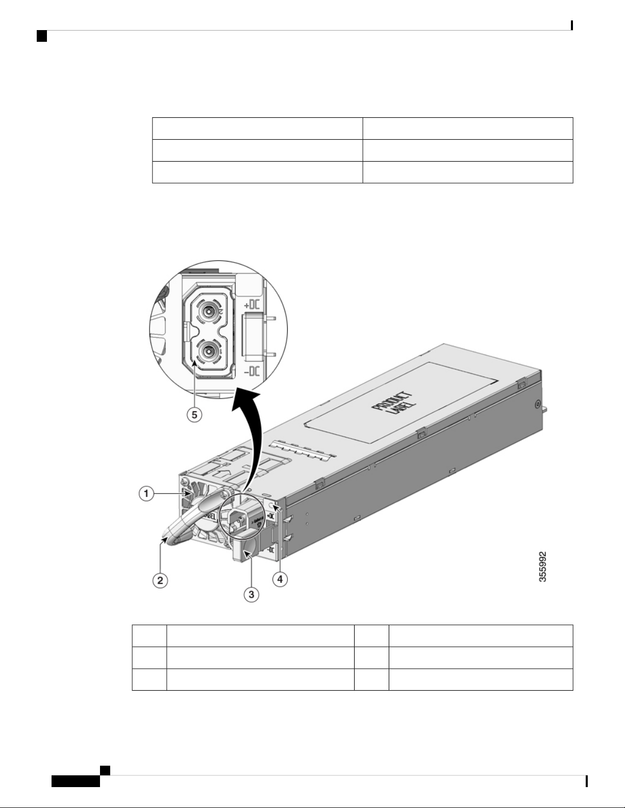
Figure 5: Cisco Catalyst 9600 Series 2000W DC Power Supply
Product Overview
Output Power in WattsInput Voltage (VAC)
2000W220VAC
1050W110VAC
LED4PSU fan1
Power cord connector5Release handle2
--Release latch3
The following are the features supported by a Cisco Catalyst 9600 Series DC power supply module:
Cisco Catalyst 9600 Series Switches Hardware Installation Guide
8
Page 13

Product Overview
• Self-cooling, with a minimum airflow of 9.5 cubic feet per minute (CFM) at 100 percent load.
• Has a release latch mechanism on the side of the module, to avoid accidental removal of the module.
• Has DC-input reversal protection such that the unit will survive this condition up to the full input voltage
rating.
• Supports redundant and combined configuration modes. A single (non-redundant) or a dual (redundant)
power supply configuration, can support the following loads:
Voltage differential between inputs is unlimited.
Power Supply Modes
Cisco Catalyst 9600 Series Switches offer redundant and combined configuration modes for power supplies.
In both the modes, the power supplies will share the load equally.
Power Supply Modes
Output PowerInput Voltage (VDC)
2000W-40 to -72VDC (with extended range to -75VDC)
Warning
The number of power supply modules installed and the system load determine the power-level that the system
expects to draw from each power supply module and consequently, the power supply mode that will be suitable.
For system power budgeting estimates and to determine power supply requirements, use the Cisco Power
Calculator.
To configure a power supply mode, enter the power redundancy-mode command in global configuration
mode. If you do not configure a mode, the default mode applies.
Combined Mode
This is the default power supply mode.
The system operates with one to four power supply modules. The power available to the system is the sum
of power outputs of all the power supply modules in the chassis multiplied by the share ratio. All available
power supply modules are active and sharing power, and can operate at up to 100 percent capacity. Additional
power supply units operate at 97 percent capacity. In combined mode, you can use a combination of AC and
DC power supplies provided the AC input voltage is 220V and that the power supplies are of equal wattage.
However, you cannot combine two AC power supplies of 110V input and 220V input.
Total combined mode power = P + (N-1) * P * (share ratio)
where P = Power output of one of the power supply units and N is the number of power supply modules used.
In case of failure in the combined mode, each operational power supply increases its output. If the output
power does not meet system requirements, then all the operational power supply modules may be overloaded
and go into overcurrent shutdown. All system power is then lost.
The following table provides details about the power output in combined mode:
Cisco Catalyst 9600 Series Switches Hardware Installation Guide
9
Page 14
Power Supply Modes
Product Overview
One Power SupplyInput voltage
Two Power
Supplies
Three Power
Supplies
Four Power
Supplies
4020W3030W2040W1050W110V
7820W5880W3940W2000W220V
Redundant (N+1) Mode
In a redundant configuration, a given power supply module can either be active, or in standby mode. In N+1
redundant mode, N is the number of active power supply modules and +1 is the power supply module configured
as the standby module.
You can configure redundancy mode in the software. When the switch is configured with N+1 redundancy,
software ensures that there is a standby power supply available and there is sufficient power available with
the active power supply modules (N). All the power supplies including active and standby will share the load
equally. . However, with a standby power supply installed, system ensures that the additional output power
available with a standby is always reserved for use in case of a failure. If the power supply mode is set to
redundant mode and the total active output power is not sufficient to meet the power requirements, the switch
will not enter the redundant mode.
You can use a combination of AC and DC power supplies provided the AC input voltage is 220V and the
power supplies must be of equal wattage. However, you cannot combine two AC power supplies of 110V
input and 220V input.
The following table provides details about the power output in N+1 redundant mode:
Four Power SuppliesThree Power SuppliesTwo Power SuppliesInput voltage
3030W2040W1050W110V
5880W3940W2000W220V
For detailed software configuration information, see the required version of the Software Configuration Guide.
In the guide, go to Contents → System Management → Environmental Monitoring and Power Management.
Cisco Catalyst 9600 Series Switches Hardware Installation Guide
10
Page 15

Preparing for Installation
• Safety Warnings, on page 11
• Site Requirements, on page 14
• Power Requirements, on page 23
• Cabling Requirements, on page 23
• Rack-Mounting Guidelines, on page 24
• Site Preparation Checklist, on page 25
Safety Warnings
Safety warnings appear throughout this publication in procedures that may harm you if you perform them
incorrectly. A warning symbol precedes each warning statement. The warnings below are general warnings
that are applicable to the entire publication.
CHAPTER 2
Warning
Warning
Warning
Warning
An exposed wire lead from a DC-input power source can conduct harmful levels of electricity. Be sure that
no exposed portion of the DC-input power source wire extends from the connector(s) or terminal block(s).
Statement 122
AC connected units must have a permanent ground connection in addition to the power cable ground wire.
NEBS-compliant grounding satisfies this requirement. Statement 284
High leakage current—earth connection essential before connecting to system power supply. Statement 342
Power Cable and AC Adapter - When installing the product, please use the provided or designated connection
cables/power cables/AC adaptors.Using any other cables/adaptors could cause a malfunction or a fire. Electrical
Appliance and Material Safety Law prohibits the use of UL-certified cables (that have the "UL or CSA" shown
on the code) for any other electrical devices than products designated by CISCO. The use of cables that are
certified by Electrical Appliance and Material Safety Law (that have "PSE" shown on the code) is not limited
to CISCO-designated products. Statement 371
Cisco Catalyst 9600 Series Switches Hardware Installation Guide
11
Page 16
Safety Warnings
Preparing for Installation
Warning
Warning
Warning
Warning
Warning
To reduce the risk of electric shock, the chassis of this equipment needs to be connected to permanent earth
ground during normal use. Statement 0445
Read the installation instructions before using, installing or connecting the system to the power source.
Statement 1004
Class 1 laser product. Statement 1008
There is the danger of explosion if the battery is replaced incorrectly. Replace the battery only with the same
or equivalent type recommended by the manufacturer. Dispose of used batteries according to the manufacturer’s
instructions. Statement 1015
This unit is intended for installation in restricted access areas. A restricted access area can be accessed only
through the use of a special tool, lock and key, or other means of security. Statement 1017
Warning
Warning
Warning
Warning
Warning
This equipment must be grounded. Never defeat the ground conductor or operate the equipment in the absence
of a suitably installed ground conductor. Contact the appropriate electrical inspection authority or an electrician
if you are uncertain that suitable grounding is available. Statement 1024
Class 1 LED product. Statement 1027
Blank faceplates and cover panels serve three important functions: they prevent exposure to hazardous voltages
and currents inside the chassis; they contain electromagnetic interference (EMI) that might disrupt other
equipment; and they direct the flow of cooling air through the chassis. Do not operate the system unless all
cards, faceplates, front covers, and rear covers are in place. Statement 1029
Only trained and qualified personnel should be allowed to install, replace, or service this equipment. Statement
1030
Hazardous voltage or energy is present on the backplane when the system is operating. Use caution when
servicing. Statement 1034
Cisco Catalyst 9600 Series Switches Hardware Installation Guide
12
Page 17

Preparing for Installation
Safety Warnings
Warning
Warning
Warning
Warning
Warning
Ultimate disposal of this product should be handled according to all national laws and regulations. Statement
1040
To prevent the system from overheating, do not operate it in an area that exceeds the maximum recommended
ambient temperature of 104°F (40°C). Statement 1047
Stability hazard. The rack stabilizing mechanism must be in place, or the rack must be bolted to the floor
before you slide the unit out for servicing. Failure to stabilize the rack can cause the rack to tip over. Statement
1048
The chassis should be mounted on a rack that is permanently affixed to the building. Statement 1049
Invisible laser radiation may be emitted from disconnected fibers or connectors. Do not stare into beams or
view directly with optical instruments. Statement 1051
Warning
Warning
Warning
Class 1M laser radiation when open. Do not view directly with optical instruments. Statement 1053
Class I (CDRH) and Class 1M (IEC) laser products. Statement 1055
Invisible laser radiation may be emitted from the end of the unterminated fiber cable or connector. Do not
view directly with optical instruments. Viewing the laser output with certain optical instruments (for example,
eye loupes, magnifiers, and microscopes) within a distance of 100 mm may pose an eye hazard. Statement
1056
Cisco Catalyst 9600 Series Switches Hardware Installation Guide
13
Page 18

Site Requirements
Preparing for Installation
Warning
Warning
IMPORTANT SAFETY INSTRUCTIONS
This warning symbol means danger. You are in a situation that could cause bodily injury. Before you
work on any equipment, be aware of the hazards involved with electrical circuitry and be familiar with
standard practices for preventing accidents. Use the statement number provided at the end of each
warning to locate its translation in the translated safety warnings that accompanied this device. Statement
1071
SAVE THESE INSTRUCTIONS
The covers are an integral part of the safety design of the product. Do not operate the unit without the covers
installed. Statement 1077
Site Requirements
Planning a proper location for the switch and layout of the equipment rack or wiring closet is essential for
successful system operation. These sections describe some of the basic site requirements that you should be
aware of as you prepare to install your switch, including the following:
• Environmental factors can adversely affect the performance and longevity of your system.
• Install the switch in an enclosed, secure area, ensuring that only qualified personnel have access to the
switch and control of the environment.
Temperature
• Equipment that is placed too closely together or that is inadequately ventilated may cause system
over-temperature conditions, leading to premature component failure.
• Poor equipment placement can make chassis panels inaccessible and difficult to maintain.
• The switch requires a dry, clean, well-ventilated, and air-conditioned environment.
• To ensure normal operation, maintain ambient airflow. If the airflow is blocked or restricted, or if the
intake air is too warm, an over-temperature condition may occur. The switch environmental monitor may
then shut down the system to protect the system components.
• Multiple switches can be rack mounted with little or no clearance above and below the chassis. However,
when mounting a switch in a rack with other equipment, or when placing it on the floor near other
equipment, ensure that the exhaust from other equipment does not blow into the air intake vent of the
switch chassis.
Temperature extremes may cause a system to operate at reduced efficiency and cause a variety of problems,
including premature aging and failure of chips, and failure of mechanical devices. Extreme temperature
fluctuations may also cause chips to become loose in their sockets. Observe the following guidelines:
• Ensure that the system is operating in an environment that is—
• 23 to 113 °F (-5 to 45 °C) up to 6000 feet (1800m)
Cisco Catalyst 9600 Series Switches Hardware Installation Guide
14
Page 19

Preparing for Installation
Air Flow
• 23 to 104 °F (-5 to 40 °C) up to 10000 feet (3000m)
• Ensure that the chassis has adequate ventilation.
• Do not place the chassis within a closed-in wall unit or on top of cloth, which can act as insulation.
• Do not place the chassis where it will receive direct sunlight, particularly in the afternoon.
• Do not place the chassis next to a heat source of any kind, including heating vents.
• Adequate ventilation is particularly important at high altitudes. Make sure that all the slots and openings
on the system remain unobstructed, especially the fan vent on the chassis.
• Clean the installation site at regular intervals to avoid buildup of dust and debris, which may cause a
system to overheat.
• If system is exposed to abnormally low temperatures, allow a two hour warm up period, in ambient
temperature no lower than 32°F (0 °C) before turning on.
Warning
Air Flow
Do not operate the system if the fan assembly is removed or if it is not functioning properly. An overtemperature
condition can cause severe equipment damage or an unscheduled system shutdown.
Failure to observe these guidelines may damage the chassis' internal components.
The switch is designed to be installed in an environment where there is a sufficient volume of air available to
cool the supervisor engines, modules, and power supplies. If there are any constraints with regard to the free
flow of air through the chassis, or if the ambient air temperature is elevated, the switch environmental monitor
may then shut down the system to protect the system components.
To maintain proper air circulation through the switch chassis, we recommend that you maintain a minimum
space of 6 inches (15 cm) between a wall and the chassis and power supply unit air intakes or a wall and the
chassis and power supply unit hot air exhausts. In situations where the switch chassis are installed in adjacent
racks, you should allow a minimum space of 12 inches (30.5 cm) between the air intake of one chassis and
the hot air exhaust of another chassis.
Note
Failure to maintain adequate spacing between chassis may cause the switch chassis that is drawing in the hot
exhaust air to overheat and fail.
Cisco Catalyst 9600 Series Switches Hardware Installation Guide
15
Page 20
Air Flow
Preparing for Installation
Figure 6: Air Flow Direction - Cisco Catalyst 9600 Series Switches
Chassis air exhaust3Chassis air intake1
Power supply air exhaust4Power supply air intake2
If you are installing your switch in an enclosed or partially enclosed rack, we strongly recommend that you
verify that your site meets the following guidelines:
• Verify that there is a minimum of 6 inches (15 cm) of clearance between the sides, front, and back of
any enclosure, and both the chassis air intake grill and the chassis air exhaust grill along with the power
supply unit intakes and exhausts. The upright columns of a relay rack may be located less than the
recommended side spacing provided there are substantial cutouts, holes, or vents in the structure to allow
adequate air flow through the chassis.
• Verify that the ambient air temperature within the enclosed or partially enclosed rack is within the chassis
operating temperature limits. After installing the chassis in the rack, power up the chassis and allow the
chassis temperature to stabilize (approximately 2 hours).
Measure the ambient air temperature at the chassis air intake grill by positioning an external temperature
probe 1 inch (2.5 cm) away from the chassis left side, and centered on the chassis both horizontally and
vertically.
Cisco Catalyst 9600 Series Switches Hardware Installation Guide
16
Page 21

Preparing for Installation
Humidity
Measure the ambient air temperature at the power supply unit air intake grill by positioning an external
temperature probe 1 inch (2.5 cm) away from the chassis front, centered on the power supply unit section
located above the card slots.
• If the ambient intake air temperature is less than 113°F (45°C) at altitudes of 6,000 feet and below,
the rack meets the intake air temperature criterion. At altitudes above that threshold and up to 10,000
feet (3000 m), the air intake should not exceed 104°F (40°C).
• If the ambient intake air temperature exceeds this recommendation, the system may experience
minor temperature alarms and increase fan speeds in response.
• If the ambient intake air temperature equals or is greater than 131°F (55°C), the system may
experience a major temperature alarm with maximum fan speeds in response. If ambient temperature
continues to increase, system will respond with protective shut down.
• Plan ahead. A switch that is currently installed in an enclosed or partially enclosed rack might meet
ambient air temperature and air flow requirements at present. However, if you add more chassis to the
rack or more modules to a chassis in the rack, the additional heat generated might cause the ambient air
temperature at the chassis or power supply unit inlets to exceed recommended conditions which may
trigger thermal alarms.
Humidity
High-humidity conditions may cause moisture to enter the system, and cause corrosion of internal components
and degradation of properties such as electrical resistance, thermal conductivity, physical strength, and size.
Extreme moisture buildup inside the system may result in electrical short circuit, which may cause serious
damage to the system. Each system is rated for storage and operation in 10 to 95 percent relative humidity,
non-condensing with a humidity gradation of 10 percent per hour. Buildings in which climate is controlled
by air-conditioning in the warmer months and by heat during the colder months usually maintain an acceptable
level of humidity for system equipment. However, if a system is located in an unusually humid location, a
dehumidifier should be used to maintain the humidity within an acceptable range.
Altitude
Operating a system at high altitude (low pressure) reduces the efficiency of forced and convection cooling
and may result in electrical problems related to arcing and corona effects. This condition may also cause sealed
components with internal pressure, such as electrolytic capacitors, to fail or perform at reduced efficiency.
Dust and Particles
Fans cool power supplies and system components by drawing in room-temperature air and exhausting heated
air out through various openings in the chassis. However, fans also ingest dust and other particles, causing
contaminant buildup in the system and increased internal chassis temperature. A clean operating environment
can greatly reduce the negative effects of dust and other particles, which act as insulators and interfere with
the mechanical components in the system. The standards listed below provide guidelines for acceptable
working environments and acceptable levels of suspended particulate matter:
• National Electrical Manufacturers Association (NEMA) Type 1
• International Electrotechnical Commission (IEC) IP-20
Cisco Catalyst 9600 Series Switches Hardware Installation Guide
17
Page 22

Corrosion
Corrosion
Corrosion of system connectors is a gradual process that may eventually lead to intermittent failures of electrical
circuits. The oil from a person’s fingers or prolonged exposure to high temperature or humidity may corrode
the gold-plated edge connectors and pin connectors on various components in the system. To prevent corrosion,
avoid touching contacts on boards and cards, and protect the system from extreme temperatures and moist,
salty environments.
EMI and Radio Frequency Interference
Electro-Magnetic interference (EMI) and radio frequency interference (RFI) from a system can adversely
affect devices such as radio and television (TV) receivers operating near the system. Radio frequencies
emanating from a system can also interfere with cordless and low-power telephones. Conversely, RFI from
high-power telephones can cause spurious characters to appear on the system monitor. RFI is defined as any
EMI with a frequency above 10 kilohertz (kHz). This type of interference can travel from the system to other
devices through the power cable and power source, or through the air in the form of transmitted radio waves.
The Federal Communications Commission (FCC) publishes specific regulations to limit the amount of EMI
and RFI emitted by computing equipment. Each system meets these FCC regulations. To reduce the possibility
of EMI and RFI, follow these guidelines:
Preparing for Installation
• Always operate the system with the chassis covers installed.
• Ensure that all chassis slots are covered by a metal filler bracket and that an unused power supply bay
has a metal cover plate installed.
• Ensure that the screws on all peripheral cable connectors are securely fastened to their corresponding
connectors on the back of the chassis.
• Always use shielded cables with metal connector shells for attaching peripherals to the system.
When wires are run for any significant distance in an electromagnetic field, interference can occur between
the field and the signals on the wires. This fact has two implications for the construction of plant wiring:
• Bad wiring practice can result in radio interference emanating from the plant wiring.
• Strong EMI, especially when it is caused by lightning or radio transmitters, can destroy the signal drivers
and receivers in the chassis, and even create an electrical hazard by conducting power surges through
lines into equipment.
Note
To predict and provide a remedy for strong EMI, consult experts in RFI.
If you use twisted-pair cable in your plant wiring with a good distribution of grounding conductors, the plant
wiring is unlikely to emit radio interference. If you exceed the recommended distances, use a high-quality
twisted-pair cable with one ground conductor for each data signal when applicable.
18
Caution
Category 5e, Category 6, and Category 6a cables can store large levels of static electricity because of the
dielectric properties of the materials used in their construction. Always ground the cables (especially in new
cable runs) to a suitable and safe earth ground before connecting them to the module.
Cisco Catalyst 9600 Series Switches Hardware Installation Guide
Page 23

Preparing for Installation
Shock and Vibration
If the wires exceed the recommended distances, or if wires pass between buildings, give special consideration
to the effect of a lightning strike in your vicinity. The electromagnetic pulse caused by lightning or other
high-energy phenomena can easily couple enough energy into unshielded conductors to destroy electronic
devices. If you have had problems of this sort in the past, you may want to consult experts in electrical surge
suppression and shielding.
Warning
The intra-building ports (Copper Based Ethernet Ports) of the equipment or subassembly is suitable for
connection to intra-building or unexposed wiring or cabling only. The intra-building ports of the equipment
or subassembly MUST NOT be metallically connected to interfaces that connect to the Out Side Plant (OSP)
or its wiring for more than 6 meters (approximately 20 feet). These interfaces are designed for use as
intra-building interfaces only (Type 2, 4, or 4a ports as described in GR-1089) and require isolation from the
exposed OSP cabling. The addition of Primary Protectors is not sufficient protection in order to connect these
interfaces metallically to an OSP wiring system.
Shock and Vibration
The equipment complies with the Earthquake, Office, and Transportation Vibration, and Equipment Handling
Criteria of GR-63-CORE.
Power Source Interruptions
Systems are especially sensitive to variations in voltage supplied by the AC power source. Overvoltage,
undervoltage, and transients (or spikes) can erase data from memory or even cause components to fail. To
protect against these types of problems, power cables should always be properly grounded. Also, place the
system on a dedicated power circuit (rather than sharing a circuit with other heavy electrical equipment). In
general, do not allow the system to share a circuit with any of the following:
• Copy machines
• Air conditioners
• Vacuum cleaners
• Space heaters
• Power tools
• Teletype machines
• Laser printers
• Facsimile machines
• Any other motorized equipment
Besides these appliances, the greatest threats to a system's power supply are surges or blackouts that are caused
by electrical storms. Whenever possible, turn off the system and peripherals, if any, and unplug them from
their power sources during thunderstorms. If a blackout occurs—even a temporary one—while the system is
turned on, turn off the system immediately and disconnect it from the electrical outlet. Leaving the system on
may cause problems when the power is restored; all other appliances left on in the area may create large
voltage spikes that may damage the system.
Cisco Catalyst 9600 Series Switches Hardware Installation Guide
19
Page 24

System Grounding
System Grounding
Preparing for Installation
Warning
Warning
Caution
When installing or replacing the unit, the ground connection must always be made first and disconnected last.
Statement 1046
Use copper conductors only. Statement 1025
You must install a system ground as part of the chassis installation process. Chassis installations that rely only
on the AC third-prong ground are insufficient to adequately ground the systems.
Proper grounding practices ensure that the buildings and the installed equipment within them have
low-impedance connections and low-voltage differentials between chassis. When you install a system ground,
you reduce or prevent shock hazards, chances of equipment damage due to transients, and the potential for
data corruption.
Without proper and complete system grounding, you run the risk of increased component damage due to ESD.
Additionally, you have a greatly increased chance of data corruption, system lockup, and frequent system
reboot situations by not using a system ground.
Installations that rely solely on system grounding that uses only an AC third-prong ground run a substantially
greater risk of equipment problems and data corruption than those installations that use both the AC third-prong
ground and a properly installed system ground.
The following table lists some general grounding practice guidelines.
Table 3: Grounding Practice Guidelines
Environment
direct lightning strikes.
For example, some places in the United
States, such as Florida, are prone to
more lightning strikes than other areas.
area where lightning storms occur
frequently, but is not prone to direct
lightning strikes.
Severity Level
HighCommercial building is subjected to
HighCommercial building is located in an
Grounding RecommendationsElectromagnetic Noise
All lightning protection devices must be
installed in strict accordance with
manufacturer recommendations.
Conductors carrying lightning current
should be spaced away from power and
data lines in accordance with applicable
recommendations and codes. Best
grounding practices must be closely
followed.
Best grounding practices must be closely
followed.
Cisco Catalyst 9600 Series Switches Hardware Installation Guide
20
Page 25

Preparing for Installation
System Grounding
Environment
of information technology equipment
and industrial equipment, such as
welding.
subject to natural environmental noise
or man-made industrial noise. This
building contains a standard office
environment. This installation has a
history of malfunction due to
electromagnetic noise.
to natural environmental noise or
man-made industrial noise. This
building contains a standard office
environment.
subject to natural environmental noise
or man-made industrial noise. This
building contains a standard office
environment.
Severity Level
Medium to HighCommercial building contains a mix
MediumExisting commercial building is not
LowNew commercial building is not subject
LowExisting commercial building is not
Grounding RecommendationsElectromagnetic Noise
Best grounding practices must be closely
followed.
Best grounding practices must be closely
followed. Determine source and cause of
noise if possible, and mitigate as closely as
possible at the noise source or reduce
coupling from the noise source to the
victim equipment.
Best grounding practices should be
followed as closely as possible.
Electromagnetic noise problems are not
anticipated, but installing a best-practice
grounding system in a new building is often
the least expensive route, and the best way
to plan for the future.
Best grounding practices should be
followed as much as possible.
Electromagnetic noise problems are not
anticipated, but installing a best-practice
grounding system is always recommended.
Note
Note
Caution
In all situations, grounding practices must comply with Section 250 of the National Electric Code (NEC)
requirements or local laws and regulations. A 6 AWG grounding wire is preferred from the chassis to the rack
ground or directly to the common bonding network (CBN). The equipment rack should also be connected to
the CBN with a 6 AWG grounding wire.
Always ensure that all of the modules are completely installed and that the captive installation screws are
fully tightened. In addition, ensure that all the I/O cables and power cords are properly seated. These practices
are normal installation practices and must be followed in all installations.
Category 5e, Category 6, and Category 6a cables can store large levels of static electricity because of the
dielectric properties of the materials used in their construction. Always ground the cables (especially in new
cable runs) to a suitable and safe earth ground before connecting them to the module.
Cisco Catalyst 9600 Series Switches Hardware Installation Guide
21
Page 26

Maintaining Safety with Electricity
Maintaining Safety with Electricity
When working on electrical equipment, follow these guidelines:
• Do not work alone if potentially hazardous conditions exist anywhere in your work space.
• Never assume that power is disconnected from a circuit; always check the circuit before working on it.
• Look carefully for possible hazards in your work area, such as damp floors, ungrounded power extension
cables, frayed or damaged power cords, and missing safety grounds.
• If an electrical accident occurs, proceed as follows:
• Use extreme caution; do not become a victim yourself.
• Disconnect power from the system.
• If possible, send another person to get medical aid. Otherwise, assess the condition of the victim
and then call for help.
• Determine if the person needs rescue breathing or external cardiac compressions; then take appropriate
action.
Preparing for Installation
• Use the product within its marked electrical ratings and product usage instructions.
• Install the product in compliance with local and national electrical codes.
• If any of the following conditions occur, contact the Cisco Technical Assistance Center:
• The power cable or plug is damaged.
• An object has fallen into the product.
• The product has been exposed to water or other liquids.
• The product has been dropped or shows signs of damage.
• The product does not operate correctly when you follow the operating instructions.
• Use the correct external power source. Operate the product only from the type of power source indicated
on the electrical ratings label. If you are not sure of the type of power source required, consult the Cisco
Technical Assistance Center or a local electrician.
• Use approved power cables only. You have been provided with one or more power cables with your
chassis power supply that are intended for use in your country, based on the shipping location. Should
you need to purchase additional power cables, ensure that they are rated for the product and for the
voltage and current marked on the product’s electrical ratings label. The voltage and current rating of
the power cable should be greater than the ratings marked on the label.
• To help prevent electrical shock, plug all the power cables into properly grounded electrical outlets.
These power cables are equipped with three-prong plugs to ensure proper grounding. Do not use adapter
plugs or remove the grounding prong from a power cable.
• Observe power strip ratings. Make sure that the total current rating of all products that are plugged into
the power strip does not exceed 80 percent of the power strip rating.
• Do not modify power cables or plugs yourself. Consult with a licensed electrician or your power company
for site modifications. Always follow your local and national wiring codes.
Cisco Catalyst 9600 Series Switches Hardware Installation Guide
22
Page 27

Preparing for Installation
Preventing Electrostatic Discharge Damage
Electrostatic discharge (ESD) damage may occur when modules or other FRUs are improperly handled, and
result in intermittent or complete failure of the modules or FRUs. Modules consist of printed circuit boards
that are fixed in metal carriers. EMI shielding and connectors are integral components of a carrier. Although
the metal carrier helps to protect the board from ESD, always use an ESD-grounding strap when handling
modules. To prevent ESD damage, follow these guidelines:
• Always use an ESD wrist or ankle strap and ensure that it makes good skin contact.
• Connect the equipment end of the strap to an unfinished chassis surface.
• When installing a component, use any available ejector levers to properly seat the bus connectors in the
backplane or midplane. These devices prevent accidental removal, provide proper grounding for the
system, and help to ensure that bus connectors are properly seated.
• When removing a component, use any available ejector levers to release the bus connectors from the
backplane or midplane.
• Handle carriers by available handles or edges only; avoid touching the printed circuit boards or connectors.
Preventing Electrostatic Discharge Damage
• Place a removed component board-side-up on an antistatic surface or in a static shielding container. If
you plan to return the component to the factory, immediately place it in a static shielding container.
• Avoid contact between the printed circuit boards and clothing. The wrist strap only protects components
from ESD voltages on the body; ESD voltages on clothing can still cause damage.
• Never attempt to remove the printed circuit board from the metal carrier.
Power Requirements
Power supplies installed on the switch chassis can be all AC-input, all DC-input, or a mix of both. When
preparing your site for switch installation, adhere to these requirements:
• In systems configured with more than one power supply, connect each of the power supplies to a separate
input power source. If you fail to do this, your system might be susceptible to total power failure due to
a fault in the external wiring or a tripped circuit breaker
• To prevent loss of input power, be sure that the total maximum load on each source circuit is within the
current ratings of the wiring and breakers.
• In some systems, you may decide to use an uninterrupted power supply (UPS) to protect against power
failures at your site. Be aware when selecting a UPS that some UPS models that use ferroresonant
technology may become unstable when operating with the switch power supplies that use power factor
correction. This may cause the output voltage waveform to the switch to become distorted, resulting in
an undervoltage situation in the system.
Cabling Requirements
When running power and data cables together in overhead cable trays or subfloor cable trays, be aware of the
following caution:
Cisco Catalyst 9600 Series Switches Hardware Installation Guide
23
Page 28

Rack-Mounting Guidelines
Preparing for Installation
Caution
Caution
We strongly recommend that power cabling runs and other potential noise sources be located as far away as
practical from LAN cabling that terminates on Cisco equipment. In situations where this type of long parallel
cable runs exist and cannot be separated by at least 3.3 feet (1 meter), we recommend that you shield these
potential noise sources. To avoid interference, the source should be shielded by housing it in a grounded
metallic conduit.
Also be aware of the following caution concerning the use of Category 5e and Category 6 Ethernet cables:
Category 5e, Category 6, and Category 6a cables can store large levels of static electricity because of the
dielectric properties of the materials used in their construction. Always ground the cables (especially in new
cable runs) to a suitable and safe earth ground before connecting them to the module.
Rack-Mounting Guidelines
Rack Specifications
Cisco Catalyst 9600 Series Switches are designed to be installed in standard, 19-inch equipment racks that
meet EIA-310-D specifications. In Network Equipment Building Systems (NEBS) compliant installation, you
can use only a 23-inch rack mount. Before rack-mounting the chassis, ensure that the equipment rack complies
with all requirements and guidelines
Mounting Location Guidelines
Cisco Catalyst 9600 Series Switches must be front-mounted.
Accordingly, you can install the chassis in 2-post or 4-post racks, but in a 4-post rack, the rear posts are not
used for mounting.
Width and Depth Requirements
Use a tape measure to verify the interior dimensions of the rack.
• Measure the space between the inner edges of the left front and right front mounting posts. The chassis
is 19 inches (48.26 cm) wide and must fit between the mounting posts.
• Measure the depth of the rack from the outside of the front mounting posts to the outside of the rear
mounting strip. The chassis is 18.8 inches (47.75 cm) deep.
Height Requirements
The rack must have sufficient clearance in terms of height, to insert the chassis. Chassis height is also measured
in rack units (RU or just U) where 1 RU or 1 U equals 1.75 inches (44.45 mm). A typical server rack is 42
RU or 42 U in height.
The chassis height of Catalyst 9606R Switch is 8 RU with a depth of 18.8 inches.
Cisco Catalyst 9600 Series Switches Hardware Installation Guide
24
Page 29

Preparing for Installation
Site Preparation Checklist
Other General Guidelines
Caution
Warning
Warning
Warning
If the equipment rack is on wheels, ensure that the brakes are engaged and that the rack is stabilized.
To prevent bodily injury when mounting or servicing this unit in a rack, you must take special precautions to
ensure that the system remains stable. The following guidelines are provided to ensure your safety:
• This unit should be mounted at the bottom of the rack if it is the only unit in the rack.
• When mounting this unit in a partially filled rack, load the rack from the bottom to the top with the
heaviest component at the bottom of the rack.
• If the rack is provided with stabilizing devices, install the stabilizers before mounting or servicing the
unit in the rack. Statement 1006
Take care when connecting units to the supply circuit so that wiring is not overloaded. Statement 1018
To prevent the system from overheating, do not operate it in an area that exceeds the maximum recommended
ambient temperature of: 104oF (40oC) Statement 1047
Note
To maintain proper air circulation through the switch chassis, we recommend that you maintain a minimum
space of 6 inches (15 cm) between a wall and the chassis and power supply unit air intakes or a wall and the
chassis and power supply unit hot air exhausts. In situations where the switch chassis are installed in adjacent
racks, you should allow a minimum space of 12 inches (30.5 cm) between the air intake of one chassis and
the hot air exhaust of another chassis. Failure to maintain adequate spacing between chassis may cause the
switch chassis that is drawing in the hot exhaust air to overheat and fail.
Site Preparation Checklist
The following table lists the site-planning activities that you should perform prior to installing the switch.
Completing each activity helps ensure a successful switch installation.
Cisco Catalyst 9600 Series Switches Hardware Installation Guide
25
Page 30

Site Preparation Checklist
Table 4: Site Preparation Checklist
Preparing for Installation
ActivityTask No.
DateTimeVerified
By
1
Space evaluation
• Space and layout
• Floor covering
• Impact and vibration
• Lighting
• Maintenance access
2
Environmental evaluation
• Ambient temperature
• Humidity
• Altitude
• Atmospheric contamination
• Airflow
3
Power evaluation
• Input power type
• Power receptacles (Depends on power supply)
2
• Receptacle proximity to the equipment.
• Dedicated (separate) circuits for redundant power supplies.
• UPS for power failures
4
Grounding evaluation
3
• Circuit breaker size
• CO ground (AC powered systems)
5
Cable and interface equipment evaluation
• Cable type
• Connector type
• Cable distance limitations
• Interface equipment (transceivers)
Cisco Catalyst 9600 Series Switches Hardware Installation Guide
26
Page 31

Preparing for Installation
Site Preparation Checklist
ActivityTask No.
By
6
EMI evaluation
• Distance limitations for signaling
• Site wiring
• RFI levels
2
Verify that each power supply installed in the chassis has a dedicated AC source circuit.
3
Refer to the power supply'VA rating as a sizing criteria in determining the output required by the UPS.
The power supply kVA rating value is listed in the specifications table for each power supply in Appendix
A (power supply specifications).
DateTimeVerified
Cisco Catalyst 9600 Series Switches Hardware Installation Guide
27
Page 32

Site Preparation Checklist
Preparing for Installation
Cisco Catalyst 9600 Series Switches Hardware Installation Guide
28
Page 33

Installing the Switch
• Unpacking the Switch, on page 29
• Install the Switch as Shipped, on page 30
• Install the Switch with Shelf Brackets, on page 36
• Install the Switch in NEBS-Compliant Mode, on page 50
• Establishing System Ground, on page 57
• Attaching an ESD Strap, on page 60
• Verifying the Switch Chassis Installation, on page 61
Unpacking the Switch
Check the contents of the shipping container:
Procedure
Step 1 Check the contents of the accessory kit. Verify that you have received all the listed equipment, including any
optional equipment you may have ordered, such as, network interface cables, transceivers, or special connectors.
Step 2 Check the modules in each slot. Ensure that the configuration matches the packing list and that all of the
specified interfaces are included.
Step 3 Store the shipping carton.
CHAPTER 3
Tip
Do not discard the shipping container when you unpack the switch. Flatten the shipping cartons and
store them with the pallet. You will require these containers if you have to move or ship the switch
in the future.
Cisco Catalyst 9600 Series Switches Hardware Installation Guide
29
Page 34

Installing the Switch
Install the Switch as Shipped
Install the Switch as Shipped
Installing the Cable Guide on the Chassis with L-Brackets Preinstalled on the Chassis
Procedure
Step 1 Position the cable guides to align with the L-brackets preinstalled on the chassis and secure the cable guides
to the L-brackets using the screws provided.
Figure 7: Attaching the Cable Guides
1
L-brackets on the chassis
Step 2 Secure the chassis to the rack rails with four screws on each side.
Cisco Catalyst 9600 Series Switches Hardware Installation Guide
30
Cable guides2Screws to attach the cable guides to the
Page 35

Installing the Switch
Installing the Cable Guide on the Chassis with L-Brackets Preinstalled on the Chassis
Figure 8: Mounting the Chassis to the Rack
Cable guide installation is complete.
Cable guide installed2Screws to attach the chassis to the rack post1
Cisco Catalyst 9600 Series Switches Hardware Installation Guide
31
Page 36

Rack-Mounting the Chassis as Shipped
Figure 9: Chassis with Cable Guide Attached
Installing the Switch
Rack-Mounting the Chassis as Shipped
This procedure shows how to rack mount the chassis as shipped.
Cisco Catalyst 9600 Series Switches Hardware Installation Guide
32
Page 37

Installing the Switch
Rack-Mounting the Chassis as Shipped
Before you begin
Warning
To prevent bodily injury when mounting or servicing this unit in a rack, you must take special precautions to
ensure that the system remains stable. The following guidelines are provided to ensure your safety:
• This unit should be mounted at the bottom of the rack if it is the only unit in the rack.
• When mounting this unit in a partially filled rack, load the rack from the bottom to the top with the
heaviest component at the bottom of the rack.
If the rack is provided with stabilizing devices, install the stabilizers before mounting or servicing the
unit in the rack.
Statement 1006
Procedure
Step 1 Insert the rear of the chassis between the mounting posts of the rack.
Step 2 Align the mounting holes in the L bracket on the switch or on the cable mount (if installed) with the mounting
holes in the equipment rack.
Cisco Catalyst 9600 Series Switches Hardware Installation Guide
33
Page 38

Rack-Mounting the Chassis as Shipped
Figure 10: Securing the Chassis to the Rack Posts
Installing the Switch
Cable guides210-32 or 12-24 pan head screws1
Step 3 Secure the chassis to the rack with either 10-32 or 12-24 pan head screws from the chassis standard accessory
kit.
Cisco Catalyst 9600 Series Switches Hardware Installation Guide
34
Page 39

Installing the Switch
Rack-Mounting the Chassis as Shipped
Figure 11: Chassis Secured to the Rack Posts
Step 4 4. Use a tape measure and level to ensure that the chassis is installed straight and level..
What to do next
After installing the chassis in its location, complete the installation process by:
1. Connecting the chassis to system ground.
2. Installing and connecting the power supplies to the power source.
3. Connecting the network interface cables to the supervisor module and line card modules. This may involve
installing transceivers before you attach the network interface cables.
Cisco Catalyst 9600 Series Switches Hardware Installation Guide
35
Page 40

Install the Switch with Shelf Brackets
4. Powering up the chassis and verifying the installation.
Install the Switch with Shelf Brackets
Installing the Shelf Kit L-Brackets
The switch chassis is shipped with two L-brackets installed on the front sides of the chassis. If you are
rack-mounting the switch using the shelf kit, these L-brackets must be removed and replaced with L-brackets
that are part of the shelf kit.
Before you begin
You have ordered and received the shelf kit.
Procedure
Installing the Switch
Step 1 Remove and discard the L-brackets and the ten mounting screws that the chassis is shipped with. Do not re-use
them during any part of the installation process.
Cisco Catalyst 9600 Series Switches Hardware Installation Guide
36
Page 41

Installing the Switch
Installing the Shelf Kit L-Brackets
Figure 12: L-Brackets the Chassis is Shipped with
Right L-bracket2Left L-bracket1
Cisco Catalyst 9600 Series Switches Hardware Installation Guide
37
Page 42

Installing the Shelf Kit L-Brackets
Figure 13: Removing L-Brackets the Chassis is Shipped With
Installing the Switch
--Mounting screws the chassis is shipped with1
Cisco Catalyst 9600 Series Switches Hardware Installation Guide
38
Page 43

Installing the Switch
Installing the Shelf Kit L-Brackets
Figure 14: Chassis Without L-Brackets
Chassis without right L-bracket2Chassis without left L-bracket1
Step 2 Unpack the L-brackets from the shelf kit.
Step 3 Using the M4 x 8 mm Phillips flat head screws in the shelf kit, secure the L-brackets to the front-left and
front-right sides of the chassis (four on each side).
Cisco Catalyst 9600 Series Switches Hardware Installation Guide
39
Page 44

Installing the Shelf Brackets and the Crossbar
Figure 15: Installing Shelf Kit L-Brackets
Installing the Switch
What to do next
Install the shelf brackets on the rack.
Installing the Shelf Brackets and the Crossbar
Install the shelf brackets and the crossbar before you install the chassis in the rack to help support the weight
of the chassis while you secure the L-brackets to the rack enclosure.
You have to front-mount the shelf brackets.
Before you begin
Determine the clearance between the insides of the left and right rails of your rack system and install the shelf
brackets accordingly. Keep these tools handy:
Cisco Catalyst 9600 Series Switches Hardware Installation Guide
40
--M4 x 8 mm Phillips flat head screws1
Page 45

Installing the Switch
Step 1 Position the support flange of the left shelf bracket on the front of the left rail. Align and secure the bracket
Step 2 Position the support flange of the right shelf bracket on the front of the right rail — make sure that it is level
Installing the Shelf Brackets and the Crossbar
• Number 1 and Number 2 Phillips screwdrivers
• 3/16-inch flat-blade screwdriver
• Tape measure and level
Procedure
to the rack by using three screws. Use either 10-32 or 12-24 pan head screws from the shelf kit.
with the left shelf bracket. Align and secure the bracket to the rack by using three screws.
Use the same type of screws for the left and right shelf bracket.
Figure 16: Installing the Shelf Brackets
1
Shelf brackets2Pan head screws from the shelf kit to secure
the shelf brackets to the rack posts
Cisco Catalyst 9600 Series Switches Hardware Installation Guide
41
Page 46

Installing the Cable Guide on the Chassis with Shelf Kit L-Bracket
Step 3 Secure the crossbar to the shelf brackets by using two M4 screws, with one screw on each side.
Figure 17: Securing the crossbar to the shelf brackets
Installing the Switch
Crossbar2M4 x 5 mm flat-head screw1
The shelf brackets and the crossbar are now securely mounted to the rack posts.
What to do next
Install the cable guide to the chassis. Two people will be required for this task.
Installing the Cable Guide on the Chassis with Shelf Kit L-Bracket
Procedure
Step 1 Position the cable guides and align with the shelf kit L-brackets installed on the chassis.
Cisco Catalyst 9600 Series Switches Hardware Installation Guide
42
Page 47

Installing the Switch
Rack-Mounting the Chassis
Figure 18: Installing the Cable Guide
Screws to mount the cable guide1
Step 2 Secure the cable guides to the L brackets using the screws (one on each side) provided.
What to do next
Rack mount the chassis to a rack installed with shelf brackets and a crossbar.
Rack-Mounting the Chassis
This procedure shows how to rack mount the chassis with shelf brackets.
Warning
Two people are required to lift the chassis. To prevent injury, keep your back straight and lift with your legs,
not your back. Statement 164
Tip
We recommend that you have a third person to assist in this procedure.
Cisco Catalyst 9600 Series Switches Hardware Installation Guide
43
Page 48

Rack-Mounting the Chassis
Installing the Switch
Warning
To prevent bodily injury when mounting or servicing this unit in a rack, you must take special precautions to
ensure that the system remains stable. The following guidelines are provided to ensure your safety:
• This unit should be mounted at the bottom of the rack if it is the only unit in the rack.
• When mounting this unit in a partially filled rack, load the rack from the bottom to the top with the
heaviest component at the bottom of the rack.
If the rack is provided with stabilizing devices, install the stabilizers before mounting or servicing the
unit in the rack.
Statement 1006
To install the switch chassis in the equipment rack, perform these steps:
Before you begin
• Install the shelf kit L brackets on the chassis and the shelf brackets and crossbar on the rack posts.
• Install the cable guide.
Procedure
Step 1 Pull out all four of the handholds on the chassis.
Cisco Catalyst 9600 Series Switches Hardware Installation Guide
44
Page 49

Installing the Switch
Rack-Mounting the Chassis
Figure 19: Chassis handholds
1
--All four of the chassis handholds pulled out and the
back end of the chassis resting on the edges of the
shelf bracket rails.
Step 2 With a person standing at each side of the chassis, insert one hand into each handhold. Slowly lift the chassis.
Avoid sudden twists or moves to prevent injury.
Step 3 Rest the back end of the chassis on the edges of the shelf bracket rails and slide it in until the first pair of
handles on both sides of the chassis are near the rack posts.
Step 4 Push in the handholds that are closest to the rack posts.
Cisco Catalyst 9600 Series Switches Hardware Installation Guide
45
Page 50

Rack-Mounting the Chassis
Figure 20: Sliding the Chassis in - Part 1
Installing the Switch
1
--Handholds closest to the rack posts, pushed
in.
Step 5 Continue sliding the chassis in until the second pair of handholds are near the rack posts. Push in the second
pair of handholds.
Cisco Catalyst 9600 Series Switches Hardware Installation Guide
46
Page 51

Installing the Switch
Rack-Mounting the Chassis
Figure 21: Sliding the Chassis in - Part 2
Second pair of handholds, pushed in.1
Step 6 Continue sliding the chassis rests completely on the shelf brackets and the crossbar. Slide in further until the
L brackets make contact with the rack posts.
Step 7 Secure the chassis to the rack with either the 10-32 or 12-24 pan head screws from the chassis standard
accessory kit.
Cisco Catalyst 9600 Series Switches Hardware Installation Guide
47
Page 52

Rack-Mounting the Chassis
Figure 22: Securing the Chassis to the Rack Posts
Installing the Switch
10-32 or 12-24pan head screws1
Cisco Catalyst 9600 Series Switches Hardware Installation Guide
48
Page 53

Installing the Switch
Rack-Mounting the Chassis
Figure 23: Chassis Secured to the Rack Posts
What to do next
After installing the chassis in its location, complete the installation process by:
1. Connecting the chassis to system ground.
2. Installing and connecting the power supplies to the power source.
Cisco Catalyst 9600 Series Switches Hardware Installation Guide
49
Page 54

Install the Switch in NEBS-Compliant Mode
3. Connecting the network interface cables to the supervisor module and line card modules. This may involve
installing transceivers before you attach the network interface cables.
4. Powering up the chassis and verifying the installation.
Install the Switch in NEBS-Compliant Mode
NEBS-Compliant Air Filter
A Network Equipment-Building System (NEBS) compliant installation allows filtered, front-to-rear airflow.
To mount the chassis in a NEBS-compliant mode with the air filter, use a 23-inch rack mount. Filter brackets
that are mounted on the side of the chassis hold the air filter.
A 23-inch rack mount is used for mounting the switch in a standard 23 inch (58.4 cm) equipment rack with
two unobstructed outer posts. This kit is not suitable for racks with obstructions (such as a power strip) that
could impair access to the field-replaceable units (FRUs) of the switch.
Installing the Switch
Rack-Mounting the Chassis in NEBS-Compliant Mode
Warning
Warning
Take care when connecting units to the supply circuit so that wiring is not overloaded. Statement 1018
To prevent the system from overheating, do not operate it in an area that exceeds the maximum recommended
ambient temperature of 40°C. Statement 1047
Before you begin
• Read Safety Warnings carefully before starting with any installation procedure to make sure you understand
the hazards and precautions.
• Place the chassis on the floor or on a sturdy table as close as possible to the rack. Leave enough clearance
to allow you to move around the chassis.
• Open the rack-mount kit and verify that all parts are included.
Note
Some equipment racks provide a power strip along the length of one of the rear posts. If your rack has this
feature, consider the position of the strip when planning fastener points. Before installing the brackets on the
chassis, determine whether to install the chassis from the front or the rear of the rack.
Cisco Catalyst 9600 Series Switches Hardware Installation Guide
50
Page 55

Installing the Switch
Step 1 Remove and discard the mounting ears and the ten mounting screws of the chassis. Do not reuse them during
Rack-Mounting the Chassis in NEBS-Compliant Mode
Procedure
any part of the installation process.
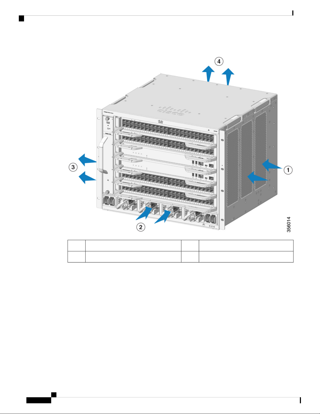
Figure 24: Remove the Mounting Ears
Mounting screws1
Step 2 Install the rack ear brackets on the left and right sides of the chassis. These brackets connect the chassis to
the rack.
Cisco Catalyst 9600 Series Switches Hardware Installation Guide
51
Page 56

Rack-Mounting the Chassis in NEBS-Compliant Mode
Figure 25: Install the Rack Ear Brackets
Installing the Switch
1
brackets
Step 3 Install the filter brackets.
Rack ear brackets2Screws to secure the rack ear
Cisco Catalyst 9600 Series Switches Hardware Installation Guide
52
Page 57

Installing the Switch
Rack-Mounting the Chassis in NEBS-Compliant Mode
Figure 26: Install the Filter Brackets
M3x6mm flat head screws1
Step 4 Install the right and the left wall covers.
Cisco Catalyst 9600 Series Switches Hardware Installation Guide
53
Page 58

Rack-Mounting the Chassis in NEBS-Compliant Mode
Figure 27: Install the Wall Covers
Installing the Switch
M4x12mm pan head screws2M4x5mm flat head screws1
Step 5 Secure the chassis to the rack with either 10-32 or 12-24 pan head screws from the chassis standard accessory
kit.
Figure 28: Secure the Chassis to Rack
10-32 or 12-24 pan head screws1
Step 6 Align the air filter with the top and the bottom edges of the air filter slot.
Cisco Catalyst 9600 Series Switches Hardware Installation Guide
54
Page 59

Installing the Switch
Rack-Mounting the Chassis in NEBS-Compliant Mode
Step 7 Insert the air filter into its housing with the arrows pointing toward the chassis. The arrows on the top edge
of the air filter note the direction of airflow. Airflow direction is from right to left, when you stand facing the
chassis.
Cisco Catalyst 9600 Series Switches Hardware Installation Guide
55
Page 60

Rack-Mounting the Chassis in NEBS-Compliant Mode
Figure 29: NEBS-Compliant Air Filter
Installing the Switch
Note
We recommend that you change the air filter every 3 months. However, examine the air filter once
a month (or more often in dusty environments) and replace it if it appears to be excessively dirty
or damaged. To comply with Telecordia GR-63-Core standard air filter requirements for NEBS
deployments, the air filter must be replaced, not cleaned.
Step 8 Install the top and base covers as shown in the illustrations:
Cisco Catalyst 9600 Series Switches Hardware Installation Guide
56
Page 61

Installing the Switch
Establishing System Ground
Figure 30: Top Cover and Base Cover
10-32 or 12-24 pan head screws1
Establishing System Ground
To attach the grounding lug and cable to the grounding pad, perform these steps:
Cisco Catalyst 9600 Series Switches Hardware Installation Guide
57
Page 62

Establishing System Ground
Before you begin
Installing the Switch
Warning
Warning
Warning
Warning
Before performing any of the following procedures, ensure that power is removed from the DC circuit.
Statement 1003
Use copper conductors only. Statement 1025
When stranded wiring is required, use approved wiring terminations, such as closed-loop or spade-type with
upturned lugs. These terminations should be the appropriate size for the wires and should clamp both the
insulation and conductor. Statement 1002
When installing or replacing the unit, the ground connection must always be made first and disconnected last.
Statement 1046
To connect the system ground, you require the following tools and materials:
• Grounding lug—A two-hole grounding lug, which supports up to 6 AWG size. Supplied as part of the
standard accessory kit.
• Grounding screws—Two M4 x 8 mm (metric) pan-head screws. Supplied as part of the standard accessory
kit.
• Grounding wire—The grounding wire should be sized according to local and national installation
requirements. Depending on the power supply and system, a 12 to 6 AWG copper conductor is required
for U.S. installations. Commercially available 6-AWG wire is recommended. The length of the grounding
wire depends on the proximity of the switch to proper grounding facilities.
• No. 1 Phillips screwdriver.
• Crimping tool to crimp the grounding wire to the grounding lug.
• Wire-stripping tool to remove the insulation from the grounding wire.
Procedure
Step 1 Use a wire-stripping tool to remove approximately 0.75 inches (19 mm) of the covering from the end of the
grounding wire.
Step 2 Insert the stripped end of the grounding wire into the open end of the grounding lug.
Step 3 Crimp the grounding wire in the barrel of the grounding lug. Verify that the ground wire is securely attached
to the ground lug.
Step 4 Secure the grounding lug to the system ground connector with two M4 screws. Ensure that the grounding lug
and the grounding wire do not interfere with other switch hardware or rack equipment.
Cisco Catalyst 9600 Series Switches Hardware Installation Guide
58
Page 63

Installing the Switch
Establishing System Ground
Figure 31: Locating and Connecting System Ground
Stripped end of the grounding wire inserted
2
into the open end of the grounding lug
Cisco Catalyst 9600 Series Switches Hardware Installation Guide
Grounding lug3M4 screws to secure the lug to the connector1
59
Page 64

Attaching an ESD Strap
Installing the Switch
Figure 32: System Ground Connected
Step 5 Prepare the other end of the grounding wire, and connect it to an appropriate grounding point in your site to
ensure adequate earth ground for the switch.
Attaching an ESD Strap
After you install the system ground lug, follow these steps to correctly attach the ESD wrist strap:
Procedure
Step 1 Attach the ESD wrist strap to bare skin as follows:
a) If you are using the ESD wrist strap supplied with the FRUs, open the wrist strap package and unwrap
the ESD wrist strap. Place the black conductive loop over your wrist and tighten the strap such that it
touches your bare skin well.
Cisco Catalyst 9600 Series Switches Hardware Installation Guide
60
Page 65

Installing the Switch
Step 2 Grasp the spring or alligator clip on the ESD wrist strap and momentarily touch the clip to a bare metal spot
Step 3 Attach either the spring clip or the alligator clip to the ground lug screw as follows:
Verifying the Switch Chassis Installation
b) If you are using an ESD wrist strap equipped with an alligator clip, open the package and remove the ESD
wrist strap. Locate the end of the wrist strap that attaches to your body and secure it to your bare skin.
(unpainted surface) on the rack. We recommend that you touch the clip to an unpainted rack rail so that any
built-up static charge is then safely dissipated to the entire rack.
a) If you are using the ESD wrist strap that is supplied with the FRUs, squeeze the spring clip jaws open,
position the spring clip to one side of the system ground lug screw head, and slide the spring clip over
the lug screw head so that the spring clip jaws close behind the lug screw head.
Note
b) If you are using an ESD wrist strap that is equipped with an alligator clip, attach the alligator clip directly
over the head of the system ground lug screw or to the system ground lug barrel.
When handling modules, follow these guidelines:
• Handle carriers using the available handles or edges only; avoid touching the printed circuit boards or
connectors.
• Place a removed component boardside up on an antistatic surface or in a static shielding container. If
you plan to return the component to the factory, immediately place it in a static shielding container.
• Never attempt to remove the printed circuit board from the metal carrier.
Caution
The spring clip jaws do not open wide enough to fit directly over the head of the lug screw or
the lug barrel.
For safety, periodically check the resistance value of the antistatic strap. The measurement
should be between 1 and 10 megohm (Mohm).
Verifying the Switch Chassis Installation
To verify the switch chassis installation, perform these steps:
Procedure
Step 1 Verify that the ejector levers of each module are fully closed (parallel to the faceplate) to ensure that the
supervisor engine and all the switching modules are fully seated in the backplane connectors.
Step 2 Verify that all empty module slots and power supply bays have blanks installed properly. The blanks optimize
the air flow through the chassis and contain EMI.
Warning
Blank faceplates and cover panels serve three important functions— They prevent exposure to
hazardous voltages and currents inside the chassis; they contain EMI that might disrupt other
equipment; and they direct the flow of cooling air through the chassis. Do not operate the system
until all cards, face plates, front covers, and rear covers are in place. Statement 1029
Cisco Catalyst 9600 Series Switches Hardware Installation Guide
61
Page 66

Installing the Switch
Verifying the Switch Chassis Installation
Step 3 Turn on the power supply switches to power up the system. During the power-up sequence, the system performs
a series of bootup diagnostic tests.
What to do next
Additional system diagnostic tests are available. These tests allow you to perform a complete sanity check on
the system prior to inserting the system into your network and to monitor the health of the system while the
system is running.
Tip
When prestaging systems in a nonproduction environment, we recommend that you run all the diagnostic
tests, including the disruptive tests, to prescreen the systems for failures, if any.
Cisco Catalyst 9600 Series Switches Hardware Installation Guide
62
Page 67

CHAPTER 4
Installing the Fan Tray
• Guidelines for Removing and Installing a Fan Tray, on page 63
• Removing a Fan Tray, on page 63
• Installing a Fan Tray, on page 70
• Verifying Fan Tray Installation, on page 73
Guidelines for Removing and Installing a Fan Tray
Before removing or installing a fan tray ensure you read and follow the guidelines and safety warnings listed
here.
Warning
Warning
Warning
Warning
When removing the fan tray, keep your hands and fingers away from the spinning fan blades. Let the fan
blades completely stop before you remove the fan tray. Statement 258
Only trained and qualified personnel should be allowed to install, replace, or service this equipment. Statement
1030
No user-serviceable parts inside. Do not open. Statement 1073
Installation of the equipment must comply with local and national electrical codes. Statement 1074
Removing a Fan Tray
The following sections explain the steps to remove a fan tray in a Cisco Catalyst 9600 Series switches.
Cisco Catalyst 9600 Series Switches Hardware Installation Guide
63
Page 68

Information About Replacing a Fan Tray
Information About Replacing a Fan Tray
Online Insertion and Removal
While the fan tray is designed to be removed and installed while the system is operating (powered on) without
presenting an electrical hazard or damage to the system, there is a time constraint when you remove and
replace the fan tray in a system that is powered on.
Installing the Fan Tray
Caution
The system can safely run without a fan tray only for a few minutes, until the critical temperature threshold
is exceeded. Watch for any alarms triggered in software. After the critical temperature threshold is exceeded
without sufficient cooling, the system shuts down if the alarm is not cleared.
When the fan tray is removed and replaced in a non-operating system, there is no time constraint.
Following the Correct Removal and Replacement Procedure
When you order a spare, only the fan tray is shipped. The connector is not shipped with a spare and you have
to use the one originally available with the fan tray assembly.
You can remove and replace the fan tray from the front or the rear. When removed from the front of the
chassis, only the fan tray is removed. When removed from the rear, the entire fan tray assembly (including
the connector) is removed.
Removal and replacement from the front is suited to situations where access to the rear of the system is
restricted. For instance, where the installation is in a closet. Removal and replacement from the rear is suited
to situations where input and output cables are routed across the front panel, limiting access to the front panel
of the fan tray.
Follow the corresponding removal and replacement procedures.
Enabling the Service Mode Before Removing the Fan Tray
This task describes how you can enable the service mode before removing the fan tray from the chassis.
Enabling the service mode pushes the fans to operate at full speed and cool down the system sufficiently,
allowing the system to sustain temperatures for the duration of servicing.
64
In a system that is operational, this applies to removal or replacement procedures from the front and the rear.
You do not have to enable this mode if you are removing and replacing the fan tray in a system that is not
powered on.
Warning
Warning
Only trained and qualified personnel should be allowed to install, replace, or service this equipment. Statement
1030
No user-serviceable parts inside. Do not open. Statement 1073
Starting in the privileged EXEC mode, enter the following command:
Cisco Catalyst 9600 Series Switches Hardware Installation Guide
Page 69

Installing the Fan Tray
Removing the Fan Tray from the Front of the Chassis
Device#test platform hardware chassis fantray service-mode on
fantray service mode on
The system automatically turns off the service mode after 10 minutes. This cools down the chassis sufficiently
for the service duration.
To turn off the service mode before this system-allotted duration, enter the following command:
Device#test platform hardware chassis fantray service-mode off
fantray service mode off
Removing the Fan Tray from the Front of the Chassis
Before you begin
• Read Guidelines for Removing and Installing a Fan Tray, on page 63.
• Enable the service mode on the chassis, if you are performing this task in a system that is powered on.
• Ensure that you have the following tools and accessories available:
• Phillips-head screwdriver
• Anti-static mat
Procedure
Step 1 Keep the replacement fan tray ready for installation.
Important
When you remove and replace the fan tray in a system that is powered on, there is a time constraint.
The system can safely run without a fan tray only for 2 minutes. So it is important to complete this
first step and its sub-steps before you remove the fan tray from the front of the chassis.
a) Remove the replacement fan tray from the shipping packaging.
b) Use the Phillips-head screwdriver and loosen the two captive installation screws on the front panel of the
replacement fan tray (the side with the fan STATUS LED), to detach it from the connector.
Cisco Catalyst 9600 Series Switches Hardware Installation Guide
65
Page 70

Removing the Fan Tray from the Front of the Chassis
Figure 33: Detaching the Connector from the Fan Tray
Installing the Fan Tray
1
Fan tray3Captive installation screws on the front of
the fan tray assembly
2
--The connector in the rear, separated from
the fan tray
The connector is not used or replaced when installed from the front. The connector can be scrapped or
stored for future use.
c) Place the replacement fan tray on an anti-static mat and within arm's reach.
Step 2 Proceed with removing the fan tray from the chassis. Loosen the two captive installation screws on the front
panel of the fan tray (the side with the fan STATUS LED).
Cisco Catalyst 9600 Series Switches Hardware Installation Guide
66
Page 71

Installing the Fan Tray
Removing the Fan Tray from the Rear of the Chassis
Figure 34: Removing the Captive Installation Screws
Captive installation screws on the front of the fan tray assembly in the chassis1
Step 3 Grasp the fan tray handle and slide the fan tray half-way out of the bay. Gently move it from side to side, if
necessary, to unseat it from the backplane.
Step 4 Wait for the fan blades to stop spinning; place your other hand underneath to support the bottom of the fan
tray and then remove the fan tray completely.
Only the fan tray is removed from the chassis (excluding the connector).
What to do next
Set the removed fan tray aside and proceed with installing the replacement or spare fan tray.
Removing the Fan Tray from the Rear of the Chassis
When you remove the fan tray from the rear, the fan tray assembly is removed. This includes the fan tray and
the connector.
Cisco Catalyst 9600 Series Switches Hardware Installation Guide
67
Page 72

Installing the Fan Tray
Removing the Fan Tray from the Rear of the Chassis
Before you begin
• Read Guidelines for Removing and Installing a Fan Tray, on page 63.
• Enable the service mode on the chassis, if you are performing this task in a system that is powered on.
• Ensure that you have the following tools and accessories available:
• Phillips-head screwdriver
• Anti-static mat
Procedure
Step 1 Keep the replacement fan tray ready by removing it from the shipping packaging. Place it on an anti-static
mat and within arm's reach. Do not detach the connector module.
Important
When you remove and replace the fan tray in a system that is powered on, there is a time constraint.
The system can safely run without a fan tray only for 2 minutes. So it is important to complete this
first step before you remove the fan tray from the rear of the chassis.
Cisco Catalyst 9600 Series Switches Hardware Installation Guide
68
Page 73

Installing the Fan Tray
Removing the Fan Tray from the Rear of the Chassis
Figure 35: Fan Tray with the Connector
Fan tray with the connector1
Step 2 Proceed with removing the fan tray from the chassis. Loosen the two captive installation screws on the rear
panel of the fan tray.
Cisco Catalyst 9600 Series Switches Hardware Installation Guide
69
Page 74

Installing a Fan Tray
Installing the Fan Tray
Figure 36: Captive Installation Screws on the Rear Panel
Step 3 Grasp the fan tray handle and slide the fan tray assembly half-way out of the bay.
Step 4 Wait for the fan blades to stop spinning; place your other hand underneath to support the bottom of the fan
tray and then remove the fan tray assembly completely.
What to do next
Set the removed fan tray aside and proceed with installing the replacement or spare fan tray.
Installing a Fan Tray
The following sections provide information about installing a fan tray in Cisco Catalyst 9600 Series switches.
Captive installation screws on the rear panel.
2Rear fan tray handle1
Note
Loosen to uninstall the fan tray
assembly from the rear.
Cisco Catalyst 9600 Series Switches Hardware Installation Guide
70
Page 75

Installing the Fan Tray
Installing the Fan Tray from the Front Panel of the Chassis
Installing the Fan Tray from the Front Panel of the Chassis
Before you begin
• Read Guidelines for Removing and Installing a Fan Tray, on page 63.
• Enable the service mode on the chassis, if you are performing this task in a system that is powered on.
• Ensure that you have the following tools and accessories available:
• Phillips-head screwdriver
• Anti-static mat
Procedure
Step 1 Hold the fan tray assembly with the fans facing to the right.
Step 2 Place the fan tray into the fan tray slot so it rests on the chassis, and then lift the fan tray up slightly, aligning
the top and bottom guides.
Figure 37: Inserting the Fan Tray from the Front of the Chassis
Fan tray without the connector2Front side of the fan tray1
Step 3 Slide the fan tray into the chassis until the two captive installation screws make contact with the chassis.
Step 4 Tighten the two captive installation screws on the front, to secure the fan tray assembly in the chassis.
Cisco Catalyst 9600 Series Switches Hardware Installation Guide
71
Page 76

Installing the Fan Tray from the Rear of the Chassis
What to do next
Verify that you have installed the fan tray correctly. See Verifying Fan Tray Installation, on page 73.
Installing the Fan Tray from the Rear of the Chassis
Before you begin
• Read Guidelines for Removing and Installing a Fan Tray, on page 63.
• Enable the service mode on the chassis, if you are performing this task in a system that is powered on.
• Ensure that you have the following tools and accessories available:
• Phillips-head screwdriver
• Anti-static mat
Procedure
Installing the Fan Tray
Step 1 On the replacement fan tray assembly, ensure that the two screws securing the fantray to the connector (on
the side with the fan STATUS LEDs) are tight. Be careful not to overtighten the screws.
Step 2 Hold the fan tray assembly such that the side with the STATUS LED is inserted first.
Figure 38: Inserting the Fan Tray from the Rear of the Chassis
Cisco Catalyst 9600 Series Switches Hardware Installation Guide
72
Page 77

Installing the Fan Tray
Verifying Fan Tray Installation
Rear panel of the fan tray.
1
2Release handle on the front of the fan tray.
Note
Step 3 Place the fan tray into the fan tray bay so it rests on the chassis, and then lift the fan tray up slightly, aligning
the top and bottom guides.
Step 4 Slide the fan tray into the chassis until the two captive installation screws make contact with the chassis.
Step 5 Tighten the two captive installation screws on the rear and secure the fan tray assembly in the chassis.
What to do next
Verify that you have installed the fan tray correctly. See Verifying Fan Tray Installation, on page 73.
Ensure that the captive installation
screws on this side are tightened
before sliding the fan tray in.
Verifying Fan Tray Installation
To verify that the new fan tray is installed correctly and is operating properly, follow these steps:
Before you begin
To check the operation of the fans, you should have powered up the chassis.
Note
Tighten the captive installation
screws on this side, after sliding the
fan tray in.
Procedure
Step 1 Listen for the fans; you should immediately hear them operating. If you do not hear them, ensure
a) That the fan tray is inserted completely in the chassis
b) That the faceplate is flush with the chassis panel.
c) That the captive installation screws have been tightened sufficiently.
Important
Step 2 Check if the fan tray LED is lit and is green.
Step 3 If after several attempts the fans do not operate, or if you experience trouble with the installation (for instance,
if the captive installation screws do not align with the chassis holes), contact the Cisco TAC for assistance.
If the fan tray is not installed correctly, the fans may not run at all, or they may run at full speed.
When the fan tray operates at full speed, increased noise levels may be expected.
Cisco Catalyst 9600 Series Switches Hardware Installation Guide
73
Page 78

Verifying Fan Tray Installation
Installing the Fan Tray
Cisco Catalyst 9600 Series Switches Hardware Installation Guide
74
Page 79

Installing a Power Supply Unit
• Required Tools and Equipment, on page 75
• Removing and Installing Power Supply Modules, on page 75
• Connecting to a Power Source, on page 82
• Verifying the Power Supply Installation, on page 86
• Removing and Installing Power Supply Blanks, on page 86
• Finding the Serial Number, on page 90
Required Tools and Equipment
Obtain these tools:
• A Phillips-head screwdriver
• A 10-mm torque driver (with a 3-inch shaft, at a minimum)
• Wire-stripping tool
• Wire crimping tool
CHAPTER 5
Removing and Installing Power Supply Modules
The chassis supports field-replaceable and hot-swappable AC-input and DC-input power supply modules.
You can install a mix of AC-input and DC-input modules in the chassis. This section describes how to remove
and install both kinds of modules
• In a redundant mode, you do not have to power down the switch to replace or upgrade the power supplies.
• In the combined mode, the module is still hot-swappable as long as the difference between total output
power and the total used power is greater than the capacity of the module being removed.
Total output power – Total used > Capacity of power supply module being removed.
Cisco Catalyst 9600 Series Switches Hardware Installation Guide
75
Page 80

Removing and Installing Power Supply Modules
Installing a Power Supply Unit
Warning
Warning
Warning
When stranded wiring is required, use approved wiring terminations, such as closed-loop or spade-type with
upturned lugs. These terminations should be the appropriate size for the wires and should clamp both the
insulation and conductor.
Statement 1002
Before performing any of the following procedures, ensure that power is removed from the DC circuit.
Statement 1003
This product relies on the building's installation for short-circuit (overcurrent) protection. Ensure that the
protective device is rated not greater than these values for US and EU:
• 20A circuit breakers for AC-input power supply.
• 50A DC-rated circuit breakers for each input for safety purposes - irrespective of whether the inputs are
power from a single or separate DC sources.
Statement 1005
Warning
Warning
Warning
Warning
Warning
This equipment has been designed for connection to TN and IT power systems.
Statement 1007
A readily accessible two-poled disconnect device must be incorporated in the fixed wiring.
Statement 1022
Use copper conductors only.
Statement 1025
Only trained and qualified personnel should be allowed to install, replace, or service this equipment.
Statement 1030
Ultimate disposal of this product should be handled according to all national laws and regulations.
Statement 1040
Cisco Catalyst 9600 Series Switches Hardware Installation Guide
76
Page 81

Installing a Power Supply Unit
Removing a Power Supply Module
Warning
This product requires short-circuit (overcurrent) protection, to be provided as part of the building installation.
Install only in accordance with national and local wiring regulations.
Statement 1045
Warning
No user-serviceable parts inside. Do not open.
Statement 1073
Warning
Hazardous voltage or energy may be present on DC power terminals. Always replace cover when terminals
are not in service. Be sure uninsulated conductors are not accessible when cover is in place.
Statement 1075
Removing a Power Supply Module
Before you begin
Warning
Only trained and qualified personnel should be allowed to install, replace, or service this equipment. Statement
1030
Warning
No user-serviceable parts inside. Do not open. Statement 1073
Procedure
Step 1 Turn the power switch of the designated power supply module to OFF (0) position
Step 2 Loosen and remove the retainer strip that is around the power cord.
Step 3 Remove the power cord from the power receptacle on the power supply.
Step 4 Press the release latch at the right side of the power supply module inwards.
Cisco Catalyst 9600 Series Switches Hardware Installation Guide
77
Page 82

Removing a Power Supply Module
Figure 39: Detaching the Power Supply Module from the Slot
Installing a Power Supply Unit
Release latch1
Step 5 Grasp the power supply module handle with one hand; place your other hand underneath to support the bottom
of the power supply. Slide the power supply module out fully.
Figure 40: Sliding the Power Supply Module Out
Caution
Do not leave any power supply slot open for any amount of time while the system is powered up.
Before inserting a new power supply unit, for instance, when replacing the unit, ensure that there
are no foreign, conductive or other objects, or debris in the slot.
Cisco Catalyst 9600 Series Switches Hardware Installation Guide
78
Page 83

Installing a Power Supply Unit
Installing a Power Supply Module
Warning
In the course of its operation the system may require more than one power supply installed and
supplying power. Should it become necessary to remove an active power supply unit from the
system, consult the user manual for proper system administration of available power. In order to
safely de-energize the power supply unit, the input power should first be turned off and the power
cable physically disconnected from the unit. The unit must then be removed from the slot and stowed
safely away in a proper antistatic bag. Care must be taken not to touch any of the exposed pins from
the backplane connector. When a replacement power supply unit is to be installed, its power switch
must always be in the OFF state and no input power cable be installed prior to inserting it into the
slot. After the unit is seated, the input power cable may then be installed and fastened securely
before switching on the power supply. Statement 1028
What to do next
Set the power supply aside and proceed with installing the new or replacement power supply module. Install
blank covers in all power supply bays that are to remain empty (C9600-PWR-BLANK). For information about
installing blank covers, see Removing and Installing Power Supply Blanks, on page 86.
Installing a Power Supply Module
Before you begin
Warning
Only trained and qualified personnel should be allowed to install, replace, or service this equipment. Statement
1030
Warning
No user-serviceable parts inside. Do not open. Statement 1073
Ensure that you have installed the cable guide before you begin the procedure. This is to properly guide and
arrange the power cords that you will attach as part of the installation.
Procedure
Step 1 Remove the replacement power supply from its shipping packaging.
Step 2 Verify that the power switch of the replacement power supply is in the OFF (0) position.
Step 3 If installed, remove the blank power supply cover from the empty power supply bay. For information about
removing blank covers, see Removing and Installing Power Supply Blanks, on page 86. Save the blank cover
for future use.
Step 4 Grasp the power supply handle with one hand and place your other hand underneath to support the bottom of
the power supply. Slide the power supply all the way into the power supply bay. Make sure that the power
supply is fully seated in the bay.
When correctly installed, the latch on the power supply locks-in the module, to avoid accidental removal of
the module.
Cisco Catalyst 9600 Series Switches Hardware Installation Guide
79
Page 84

Installing a Power Supply Module
Figure 41: Inserting the Power Supply into the Power Supply Bay
Installing a Power Supply Unit
Power supply latches, which click into place1
Step 5 Verify that all site power and grounding requirements have been met.
Step 6 Verify that you have the correct power cord for your location and power supply rating and only then plug the
power cord connector into the power supply receptacle.
Cisco Catalyst 9600 Series Switches Hardware Installation Guide
80
Page 85

Installing a Power Supply Unit
Figure 42: Plugging in the Power Cord
Installing a Power Supply Module
Power cord plugged into the receptacle1
Step 7 Follow the steps to install the power cord retainer, to hold it in place and avoid accidental removal.
a) Fix the strap in the power cord retainer to the power supply module, to hold the clamp in place.
b) Slide the retainer clamp around the power cord and position the retainer closest to the power supply.
Depending on the width of the power cord, adjust the size of the retainer clamp, if required.
c) Press the tabs on the retainer clamp towards each other to secure the power cord.
Cisco Catalyst 9600 Series Switches Hardware Installation Guide
81
Page 86

Connecting to a Power Source
Installing a Power Supply Unit
Figure 43: Installing the Power Cord Retainer
1
Step 8 Set the power switch to the ON (|) position
What to do next
Connect the power supply to the power source.
Power supply fully inserted into the chassis; power cord and retainer strapped into
place.
Connecting to a Power Source
The following sections provide information about connecting the chassis to an AC and DC power source.
Connecting to an AC Power Source
To connect to a power source, follow these steps:
Warning
Take care when connecting units to the supply circuit so that wiring is not overloaded. Statement 1018
Cisco Catalyst 9600 Series Switches Hardware Installation Guide
82
Page 87

Installing a Power Supply Unit
Procedure
Step 1 Prior to connecting the power supply to a power source, ensure that the chassis is properly grounded.
Step 2 Plug the power cable into the power supply.
Step 3 Plug the other end of the power cable into a power source supplied by the data center.
Connecting to a DC Power Source
Note
When using redundant mode, connect each power supply to a separate power source.
Step 4 Verify that the power supply is receiving power by checking that the LED is on and is green. For more
information about the power supply LEDs and the conditions that they indicate, see Power Supply Modules
LEDs, on page 97.
When you first activate the power supply, you can verify the functionality of the LED by checking that LED
turns on for a couple of seconds. If the LED is flashing amber or green, check the power connections on the
power supply and the power source.
Connecting to a DC Power Source
To connect the DC power supply directly to one or two DC power sources, follow these steps:
Warning
Warning
Before performing any of the following procedures, ensure that power is removed from the DC
circuit.Statement 1003
Hazardous voltage or energy may be present on DC power terminals. Always replace cover when terminals
are not in service. Be sure uninsulated conductors are not accessible when cover is in place. Statement 1075.
Procedure
Step 1 Prior to connecting the power supply to a power source, ensure that the chassis is properly grounded.
Step 2 Plug the DC power cable into the DC power receptacle on the power supply module.
Cisco Catalyst 9600 Series Switches Hardware Installation Guide
83
Page 88

Connecting to a DC Power Source
Figure 44: Plugging in the DC Power Cable
Installing a Power Supply Unit
Power Cable1
Step 3 Turn off the power at the circuit breakers for the portions of the DC grid power that you are connecting to
and verify that all of the LEDs on the DC grid power supplies are off.
Step 4 Install the two cables from the DC power cable to a DC power source as follows:
a) If the unconnected end of each power cable is not stripped of its insulation for the last 0.75 inches (19
mm), use wire strippers to remove that amount of insulation.
b) Attach the negative cables to the negative terminals of a DC power source, and attach the positive cables
to the positive terminals of the same power source.
Cisco Catalyst 9600 Series Switches Hardware Installation Guide
84
Page 89

Installing a Power Supply Unit
Connecting to a DC Power Source
Figure 45: Attaching the Cable to the Power Source
Negative terminal2Positive terminal1
Note
If you are using combined power mode or power supply redundancy mode, connect all the power
supplies in the chassis to the same power source. If you are using input source redundancy mode
or full redundancy mode, connect half the power supplies to one DC power source and the other
half of the power supplies to another DC power source.
Step 5 Verify that the power supply is receiving power by checking that the LED is on and is green.
When you first activate the power supply, you can verify the functionality of the LED by checking that LED
turns on for a couple of seconds. If the LED is flashing amber or green, check the power connections on the
power supply and the power source.
Cisco Catalyst 9600 Series Switches Hardware Installation Guide
85
Page 90

Verifying the Power Supply Installation
Verifying the Power Supply Installation
Procedure
Step 1 Verify the power supply operation by checking the power supply’s front-panel LED. See Power Supply
Modules LEDs, on page 97.
Step 2 Check the power supply and system status from the system console by entering show power command in
privileged EXEC mode.
Switch# show power
Step 3 If the LEDs or show power command output indicate a power problem or other system problem, see the
Troubleshooting section for more information.
Installing a Power Supply Unit
Removing and Installing Power Supply Blanks
If a power supply bay in a chassis is unused, you must cover it with a power supply blank cover to maintain
proper airflow through the chassis. (Part number C9606-PWR-BLANK=).
Cisco Catalyst 9600 Series Switches Hardware Installation Guide
86
Page 91

Installing a Power Supply Unit
Figure 46: Front View of a Power Supply Blank Cover
Removing and Installing Power Supply Blanks
Retainer clip2Release handles1
Removing a Power Supply Blank Cover
To remove the blank cover from a bay, use the release handles to hold the blank cover (with your thumb and
index fingers), squeeze both the handles toward each other and slide the cover out of the bay.
Cisco Catalyst 9600 Series Switches Hardware Installation Guide
87
Page 92

Removing and Installing Power Supply Blanks
Figure 47: Removing a Power Supply Blank Cover
Installing a Power Supply Unit
Caution
Release handles that are squeezed toward each other1
Do not leave any power supply slot open for any amount of time while the system is powered up. Prior to
inserting a new power supply unit, for instance, when replacing the unit, ensure there are no foreign, conductive
or other objects, or debris in the slot.
Installing a Power Supply Blank Cover
To install a power supply blank cover, push the blank cover straight and into the bay. You will hear retainer
clips snap into place when installed correctly. You can hold the blank cover by the outside edges when you
perform this task; alternatively, use the release handles to hold the blank cover.
Cisco Catalyst 9600 Series Switches Hardware Installation Guide
88
Page 93

Installing a Power Supply Unit
Figure 48: Installing a Power Supply Blank Cover
Removing and Installing Power Supply Blanks
Power supply blank1
Figure 49: Power Supply Blank Cover Installed
Power supply blanks after installation1
Note
Power supply blank covers can be placed in any slot when fewer than 4 power supplies are installed in a
chassis.
Cisco Catalyst 9600 Series Switches Hardware Installation Guide
89
Page 94

Finding the Serial Number
Finding the Serial Number
If you contact Cisco Technical Assistance, you need to know the serial number. These figures show where
the serial number is located. You can also use the show version privileged EXEC command to see the serial
number.
Figure 50: Serial Number on the Power Supply Module
Installing a Power Supply Unit
--Power supply module serial number1
Cisco Catalyst 9600 Series Switches Hardware Installation Guide
90
Page 95

APPENDIX A
Technical Specifications
• C9606R Switch Chassis Specifications, on page 91
• Power Supply Specifications, on page 93
• Chassis and Module Power and Heat Values, on page 95
• Weight Specifications, on page 96
C9606R Switch Chassis Specifications
Table 5: Physical Specifications of the Chassis
SpecificationItem
13.95 X 17.4 X 16.1 inches (35.43 x 44.2 x 40.9 cms)Dimensions (H x W x D)
8 RURack units (RU4)
63.0 lb (31.31 kg)Weight (Chassis with two AC power supplies and fan
tray)
4
The chassis height is measured in rack units (RU or just U), where 1 RU or 1 U equals 1.75 in (44.45
mm).
Table 6: Environmental Specifications of the Chassis
SpecificationItem
Ambient temperature and
altitude for normal
operations
Ambient temperature and
altitude for short-term
exceptional conditions
temperature
5
6
• 23° to 113°F (-5 to +45ºC), up to 6,000 feet (1800 m)
• 23° to 104°F (-5 to +40ºC), up to 10,000 feet (3000 m)
• 23°F to 122°F (-5ºC to +50ºC), up to 6,000 feet (1800 m)
• 23°F to 122°F (-5ºC to +45ºC), up to 10,000 feet (3000 m)
-40° to 167°F (-40° to 75°C)Nonoperating and storage
Cisco Catalyst 9600 Series Switches Hardware Installation Guide
91
Page 96

Technical Specifications
Technical Specifications
SpecificationItem
Thermal transition
(noncondensing)
nonoperating)
Sound power level
(LwAD)
Airflow
Shock
Sine Vibration
Hot to cold—at a maximum rate of 86°F (30°C) per hour
Cold to hot—at maximum rate of 204.8°F (96°C) per hour
Operating, nonoperating and storage —10 to 95 percentHumidity (RH), ambient
-60 to 3000m (-197 to 9843 feet)Altitude (operating and
LwAD—74.7 dBA
This is with four power supply modules installed and delivering 50 percent of
rated output power; measured according to International Organization for
Standardization (ISO) 7779 and declared according to ISO 9296.
Chassis—Right to left (when facing the front of the chassis)
Power supply—Front to back (forward air flow)
Operating—5G 11ms (Half-sine)
Nonoperating and storage— 15G 11ms (Half-sine)
• Operating— 0.15G (10Hz-500Hz)
• Nonoperating and storage— 0.8G (10Hz-500Hz)
Random Vibration
(Operating)
Spectral Break Point
Frequencies
Density
SlopeAcceleration Spectral
6 db /octave-2.5 – 5 Hz
5 – 100 Hz
-0.1 [(m/s²)²]/Hz
(0.001 g²/Hz)
-24 db /octave-100 – 200 Hz
Random Vibration
(Nonoperating and
Spectral Break Point
Frequencies
Acceleration Spectral
Density
Slope
Storage)
6 db /octave-2.5 – 5 Hz
5 – 100 Hz
-1.0 [(m/s²)²]/Hz*
(0.01 g²/Hz)
-24 db /octave-100 – 200 Hz
5
Minimum ambient temperature for cold startup is 0ºC
6
Short-term exceptional conditions are for no longer than a one-year period of—96 consecutive hours,
or 360 hours total, or 15 occurrences.
Cisco Catalyst 9600 Series Switches Hardware Installation Guide
92
Page 97

Technical Specifications
Power Supply Specifications
2000W AC-Input Power Supply Specifications
The following table lists specifications for the 2000W AC input power supply:
Table 7: 2000W AC-Input Power Supply Specifications
DescriptionSpecification
Power Supply Specifications
AC-input type
AC-input voltage
AC-input current
Branch circuit
requirement
Wide-ranging input with power factor correction.
Note
Low-line (115 VAC nominal)—90VAC (min) to 140VAC (max)
High-line (230 VAC nominal)—180VAC (min) to 264VAC (max)
10.5A at 115VAC (1050W output)
7.8A at 230 VAC (2000W output)
50/60Hz nominal (47 to 63Hz full range)AC-input frequency
Each chassis power supply should have its own dedicated, fused-branch circuit:
Power factor correction is a standard feature on AC-input power supplies.
Power factor correction reduces the reactive component in the source
AC current, allowing higher power factors and lower harmonic current
components.
• North America—15 A.
• International—Circuits sized to local and national codes.
• All AC power supply inputs are fully isolated.
• Source AC can be out of phase between multiple power supplies in the
same chassis, which means that PS1 can be operating from phase A and
PS2 can be operating from phase B.
Power supply output
• For high-line operation, the power supply operates with the line conductor
wired to an source AC phase, and the Neutral conductor wired either to
a Neutral, single-phase power system, or to another source AC phase as
long as the net input voltage is in the range of 180 to 264 VAC.
• 100 to 120 VAC operation
• 12V output — 1050W
• 200 to 240 VAC operation
• 12V output — 2000W
20 ms minimum with 1200W outputOutput holdup time
Cisco Catalyst 9600 Series Switches Hardware Installation Guide
93
Page 98

2000W DC-Input Power Supply Specifications
DescriptionSpecification
7
2250W maximum (total output power)kVA rating
683 BTU per hourHeat dissipation (in
British Thermal Units
(BTU))
2.65 lb (1.2 kg)Weight
7
The kVA rating listed for the power supply should be used as the sizing criteria for both UPS outputs
as well as standard circuits and transformers to power a switch
2000W DC-Input Power Supply Specifications
The following table lists specifications for the 2000W DC input power supply:
Table 8: 2000W DC-Input Power Supply Specifications
Technical Specifications
capacity
Temperature
Humidity
Altitude
DescriptionSpecification
-40 to -72VDC, with extended range to -75VDCDC-input voltage
Maximum: 50A per DC input at -48VDC inputDC-input current
For 12VDC output—2000WPower supply output
5ms with 1200W outputOutput holdup time
• Steady State Operating: -5°C to 45°C
• Non-operating: -40°C to +70°C
• Operating: 5 to 90 percent, non-condensing
• Non-operating: 5 to 95 percent, non-condensing
• Operating: -500 to 10,000 feet over allowable temperature range (-5 to +45°C)
and full load, de-rating 1.4°C per 1000 feet above 6,000 feet
Note
The operating altitude in China is 6,561.6 ft. (2000 m) maximum
• Non-operating: -1,000 to 50,000 feet over allowable temperature range
932 BTU per hour (maximum)Heat dissipation (in
British Thermal Units
(BTU))
2.82 lb (1.28 kg)Weight
Cisco Catalyst 9600 Series Switches Hardware Installation Guide
94
Page 99

Technical Specifications
Chassis and Module Power and Heat Values
Chassis and Module Power and Heat Values
The following tables provide the power and heat dissipation data. Unless otherwise noted, the information in
the tables is measured under fully loaded conditions (transceivers installed).
Note
DC output power is the output from the power supply (internal to the system). The AC-input power is the
input from the outlet to the power supply. The percentage difference between the two values is the efficiency
of the power supply.
Table 9: Power Requirements and Heat Dissipation - Fan Tray
PID
AC-Input
Power in
Watts
(Power
DC-Output in
Watts
(Power
Requested)
Current @
90V
Current @
120V
Allocated)
Table 10: Power Requirements and Heat Dissipation - Supervisor Module
PID
AC-Input
Power in
Watts
(Power
DC-Output in
Watts
(Power
Requested)
Current @
90V
Current @
120V
Allocated)
Table 11: Power Requirements and Heat Dissipation— Line Cards
PID
AC-Input
Power in
Watts
(Power
DC-Output in
Watts
(Power
Requested)
Current @
90V
Current @
120V
Allocated)
180V
Current @
180V
Current @
180V
Current @ 240VCurrent @
Current @
240V
Current @
240V
Heat Diss.
in BTU /
hr.
17062.12.84.25.6450500C9606-FAN
Heat Diss. in
BTU / hr.
29423.64.87.29.6775862C9600-SUP-1
Heat Diss. in
BTU / hr.
Cisco Catalyst 9600 Series Switches Hardware Installation Guide
8741.11.52.22.9230256C9600-LC-48YL
76111.31.92.5200223C9600-LC-24C
95
Page 100

Weight Specifications
Weight Specifications
The total weight of a fully configured chassis will depend on the type of chassis, the number of modules, and
power supplies installed. Use the corresponding weights in the tables below to arrive at the total chassis weight
for your hardware configuration.
Chassis Weights
Technical Specifications
PID (add = for spare)
Supervisor Module Weight
Line Card Weights
Power Supply Module Weights
Weight (Chassis without Fan Tray and Power Supply
Units)
55.90 lb (25.36 kg)C9606R
WeightPID (add = for spare)
12.02 lb (5.45 kg)C9600-SUP-1
WeightPID (add = for spare)
7.83 lb (3.55 kg)C9600-LC-48YL
7.67 lb (3.48 kg)C9600-LC-24C
WeightPID (add = for spare)
2.65 lb (1.2 kg)C9600-PWR-2KWAC
2.82 lb (1.28 kg)C9600-PWR-2KWDC
Blank Covers
WeightPID (add = for spare)
2.87 lb (1.3 kg)C9606-SLOT-BLANK
(Cisco Catalyst 9600 Series Blank for Chassis Module
Slot)
0.18 lb (0.08 kg)C9606-PWR-BLANK
(Cisco Catalyst 9600 Series Blank for Chassis Power
Supply Slot)
Cisco Catalyst 9600 Series Switches Hardware Installation Guide
96
 Loading...