

Cisco Catalyst 9404R Switch, Catalyst 9400 Series, Catalyst 9407R, Catalyst 9410R Hardware Installation Manual
Page 1

Cisco Catalyst 9400 Series Switches Hardware Installation Guide
First Published: 2017-09-20
Last Modified: 2018-08-15
Americas Headquarters
Cisco Systems, Inc.
170 West Tasman Drive
San Jose, CA 95134-1706
USA
http://www.cisco.com
Tel: 408 526-4000
800 553-NETS (6387)
Fax: 408 527-0883
Page 2

Contents
CONTENTS
CHAPTER 1
CHAPTER 2
Safety Warnings 1
Product Overview 3
Switch Models 3
Catalyst 9404R Switch 3
Catalyst 9407R Switch 8
Catalyst 9410R Switch 12
Fan Tray Assembly 17
Fan Tray Assembly Overview 17
Operation 18
High Availability 19
Thresholds, Alarms, and Abnormal Acoustic Conditions 19
Power Supply Module 20
Power Supply Module Overview 20
Power Supply Modes 22
Installation Considerations - Power Supply Modules of Different Capacities 23
CHAPTER 3
ii
Preparing for Installation 25
Safety Warnings 25
Site Requirements 26
Temperature 27
Air Flow 27
Humidity 29
Altitude 29
Dust and Particles 29
Cisco Catalyst 9400 Series Switches Hardware Installation Guide
Page 3

Corrosion 30
EMI and Radio Frequency Interference 30
Shock and Vibration 31
Power Source Interruptions 31
System Grounding 31
Maintaining Safety with Electricity 33
Preventing Electrostatic Discharge Damage 34
Power Requirements 35
Cabling Requirements 36
Rack-Mounting Guidelines 36
Site Preparation Checklist 38
Contents
CHAPTER 4
CHAPTER 5
Standard Accessory Kit Contents 41
Installing the Switch 43
Installation Tasks 43
Unpacking the Switch 45
Install the Switch as Shipped 46
Rack-Mounting the Chassis as Shipped 46
Install the Switch with Shelf Brackets 49
Shelf Kit Contents 49
Installing the Shelf Kit L Brackets 50
Installing the Shelf Brackets 53
Rack-Mounting the Chassis 55
Installing the Cable Guide 61
Installing the Cable Guide With Shelf Brackets 61
Installing the Cable Guide Without Shelf Brackets 64
Install the Switch in a NEBS-Compliant Mode 66
NEBS-Compliant Air Filter 66
Rack-Mounting the Chassis in a NEBS-Compliant Mode 67
Establishing System Ground 74
Attaching an ESD Strap 76
Verifying the Switch Chassis Installation 77
Cisco Catalyst 9400 Series Switches Hardware Installation Guide
iii
Page 4

Contents
CHAPTER 6
CHAPTER 7
Removing and Replacing FRUs 79
Removing and Installing the Fan Tray 79
Enabling the Service Mode Before Removing the Fan Tray 80
Removing the Fan Tray from the Front 80
Installing the Fan Tray from the Front 83
Removing the Fan Tray from the Rear 84
Installing the Fan Tray from the Rear 87
Verifying Fan Tray Installation 88
Removing and Installing the Power Supply 89
Installing the Power Supply 89
Removing the Power Supply 92
Removing and Installing Power Supply Blanks 96
Power Cord Retainer Mechanism 98
Verifying the Power Supply Installation 103
Troubleshooting 105
About this Section 105
System Boot Verification 105
Using LEDs to Identify Startup Problems 106
System Messages 107
Troubleshooting with Software 107
Troubleshooting the Power Supply 107
Useful Cisco IOS Commands - Power Supply 108
Troubleshooting the Fan Tray Assembly 109
Useful Cisco IOS Commands - Fan Tray Assembly 110
Troubleshooting High Temperature Alarms 110
Troubleshooting the Switching Module 111
Useful Cisco IOS Commands - Switching Modules 111
Troubleshooting Supervisor Modules 111
Supervisor Module LEDs 111
Standby Supervisor Engine Problems 111
Switch Self Reset 112
Cannot Connect to a Switch Through the Console Port 113
Cisco Catalyst 9400 Series Switches Hardware Installation Guide
iv
Page 5

Boot Problems 115
Contacting the Cisco Technical Assistance Center 115
Contents
CHAPTER 8
CHAPTER 9
Specifications 117
Chassis Specifications 117
Catalyst 9404R Switch Chassis Specifications 117
Catalyst 9407R Switch Chassis Specifications 119
Catalyst 9410R Switch Chassis Specifications 120
Power Supply Specifications 122
3200 W AC-Input Power Supply Specifications 122
3200 W Power Supply AC Power Cords 123
2100 W AC-Input Power Supply Specifications 126
2100 W Power Supply AC Power Cords 127
Chassis and Module Power and Heat Values 130
Weight Specifications 131
LEDs 133
Fan Tray LEDs 133
Power Supply LEDs 134
CHAPTER 10
Cisco Catalyst 9400 Series Switching Module LEDs 134
Cisco Catalyst 9400 Series Supervisor Module LEDs 135
Initial Configuration for the Switch 139
Options for Initial Configuration 139
Configuring the Switch Using the Web User Interface 139
Setting up the Switch 139
Connecting to the Switch 140
Creating User Accounts 140
Choosing Setup Options 141
Configuring Basic Device Settings 141
Configuring Your Device Based on a Site Profile 142
Configuring Switch Wide Settings 148
Configuring VLAN Settings 148
Configure STP Settings 148
Cisco Catalyst 9400 Series Switches Hardware Installation Guide
v
Page 6

Contents
Configuring DHCP, NTP, DNS and SNMP Settings 149
Configuring Port Settings 150
Configuring the Switch Using the CLI 151
Starting the Terminal-Emulation Software 151
Connecting to a Power Source 152
Connecting the RJ-45 Console Port 153
Connecting the USB Console Port 153
IP Settings 154
Performing the Initial Configuration 154
Configuring the Switch in the ROMMON Mode 157
Configuring the Switch in the ROMMON Mode 157
Installing and Uninstalling the USB Driver 158
Installing the Cisco Microsoft Windows USB Device Driver 158
CHAPTER 11
Installing the Cisco Microsoft Windows XP USB Driver 158
Installing the Cisco Microsoft Windows 2000 USB Driver 158
Installing the Cisco Microsoft Windows Vista and Windows 7 USB Driver 159
Uninstalling the Cisco Microsoft Windows USB Driver 159
Uninstalling the Cisco Microsoft Windows XP and 2000 USB Driver 159
Uninstalling the Cisco Microsoft Windows Vista and Windows 7 USB Driver 160
Related Documentation 161
Cisco Catalyst 9400 Series Switches Hardware Installation Guide
vi
Page 7

CHAPTER 1
Safety Warnings
Safety warnings appear throughout this publication in procedures that may harm you if you perform them
incorrectly. A warning symbol precedes each warning statement. The warnings below are general warnings
that are applicable to the entire publication.
Warning
Warning
Warning
Warning
Warning
Warning
Class 1 laser product. Statement 1008
Only trained and qualified personnel should be allowed to install, replace, or service this equipment. Statement
1030
Hazardous voltage or energy is present on the backplane when the system is operating. Use caution when
servicing. Statement 1034
Invisible laser radiation may be emitted from disconnected fibers or connectors. Do not stare into beams or
view directly with optical instruments. Statement 1051
Class 1M laser radiation when open. Do not view directly with optical instruments. Statement 1053
Class I (CDRH) and Class 1M (IEC) laser products. Statement 1055
Cisco Catalyst 9400 Series Switches Hardware Installation Guide
1
Page 8

Safety Warnings
Warning
Invisible laser radiation may be emitted from the end of the unterminated fiber cable or connector. Do not
view directly with optical instruments. Viewing the laser output with certain optical instruments (for example,
eye loupes, magnifiers, and microscopes) within a distance of 100 mm may pose an eye hazard. Statement
1056
Cisco Catalyst 9400 Series Switches Hardware Installation Guide
2
Page 9

Product Overview
• Switch Models, on page 3
• Fan Tray Assembly, on page 17
• Power Supply Module, on page 20
Switch Models
Catalyst 9404R Switch
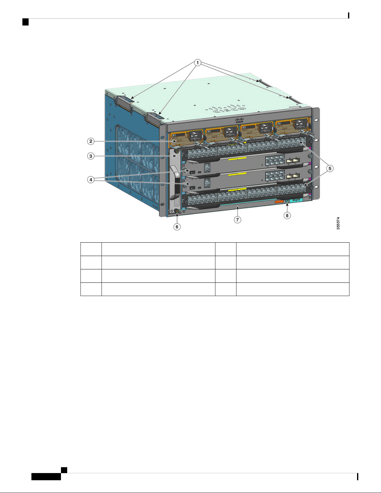
The Catalyst 9404R Switch is a four-slot modular chassis, with two redundant supervisor module slots, two
switching module slots with up to 96 front panel ports, one nonredundant fan tray assembly, and has a provision
to accommodate up to four power supply modules.
Front View of the Catalyst 9404R Switch
The figure shows a front view of the chassis, with the major components identified:
CHAPTER 2
Cisco Catalyst 9400 Series Switches Hardware Installation Guide
3
Page 10
Catalyst 9404R Switch
Product Overview
Switching module slots (1,and 4)5Chassis handholds1
Chassis Radio Frequency ID (RFID)6Power supply modules2
Chassis model number7Fan tray assembly3
System ground8Supervisor module slots (2 and 3)4
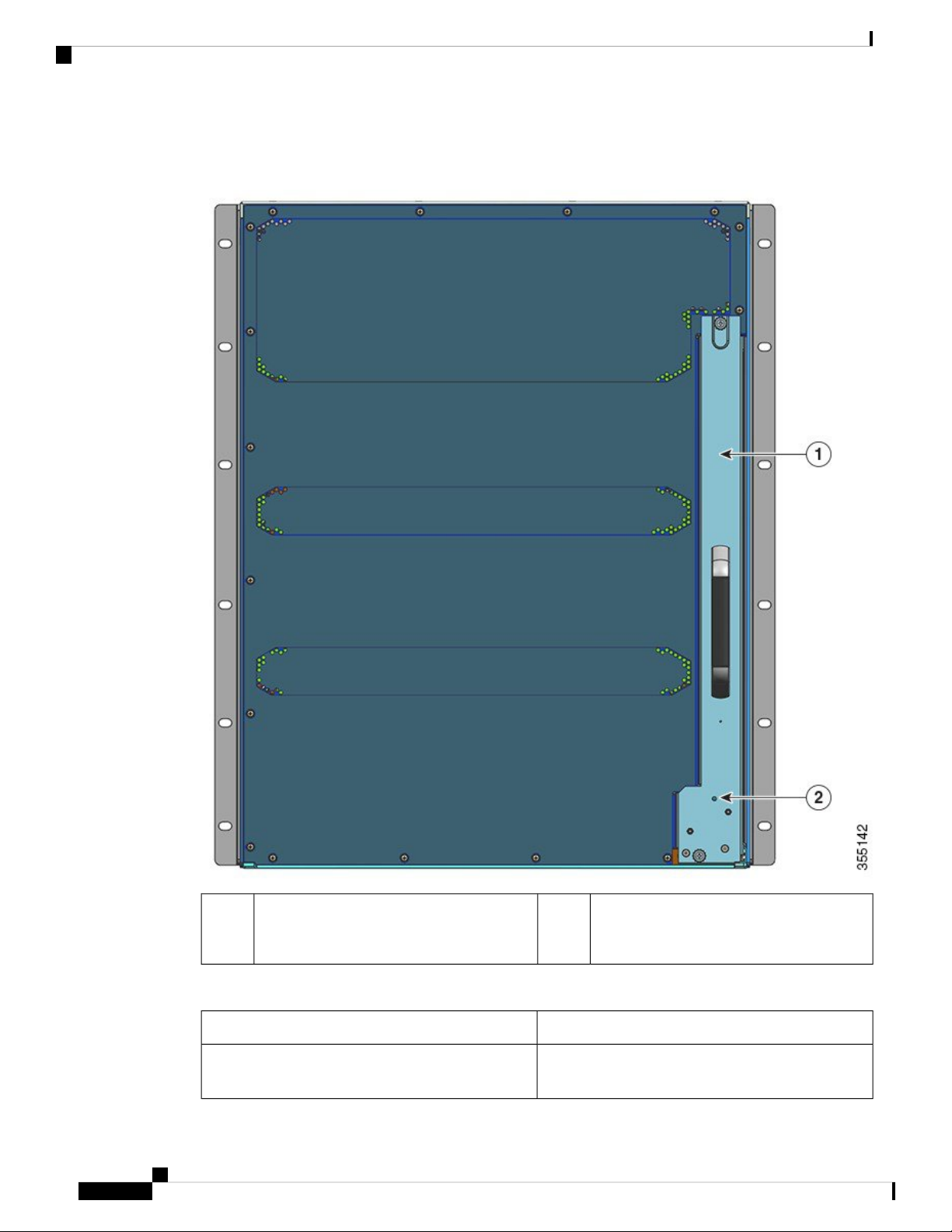
Rear View of the Catalyst 9404R Switch
The figure shows a rear view of the chassis, with the major components identified:
Cisco Catalyst 9400 Series Switches Hardware Installation Guide
4
Page 11

Product Overview
Catalyst 9404R Switch
Table 1: Catalyst 9404R Switch Features
Product ID
Chassis
2Access to remove fan tray from the rear1
Blue beacon LED on the rear panel of the fan
tray (always matches the blue beacon on the
front panel of the fan tray)
DescriptionFeature
C9404R—Cisco Catalyst 9400 Series 4 Slot Chassis
C9404R= (Spare)
Has four horizontal slots. Slots are numbered 1 (left)
to 4 (right).
Cisco Catalyst 9400 Series Switches Hardware Installation Guide
5
Page 12

Catalyst 9404R Switch
Product Overview
DescriptionFeature
Supervisor modules
Supports 1+1 supervisor module redundancy for
integrated resiliency. Supported model numbers:
Cisco Catalyst 9400 Series Supervisor 1 Module
(C9400-SUP-1) and the module spare C9400-SUP-1=
Cisco Catalyst 9400 Series Supervisor 1XL Module
( C9400-SUP-1XL) and the module spare
C9400-SUP-1XL=
Cisco Catalyst 9400 Series Supervisor 1XL25G
Module (C9400-SUP-1XL-Y) and the module spare
C9400-SUP-1XL-Y=
Supervisor modules:
• Must be installed in slots numbered 2 and 3 only.
• Have minimum software release version
requirements. Refer to your software release
notes for this information.
See Cisco Catalyst 9400 Series Supervisor Module
Installation Note.
Cisco Catalyst 9400 Series Switches Hardware Installation Guide
6
Page 13

Product Overview
Catalyst 9404R Switch
DescriptionFeature
Switching modules
Accommodates two line cards. Supported model
numbers:
• Cisco Catalyst 9400 Series 48-Port UPOE
10/100/1000 Module (C9400-LC-48U) and the
module spare (C9400-LC-48U=)
• Cisco Catalyst 9400 Series 48-Port 10/100/1000
Module (C9400-LC-48T) and the module spare
(C9400-LC-48T=)
• Cisco Catalyst 9400 Series 24-Port SFP/SFP+
Module (C9400-LC-24XS) and the module spare
(C9400-LC-24XS=).
• Cisco Catalyst 9400 Series 48-Port UPOE
Multigigabit Module (C9400-LC-48UX) and the
module spare (C9400-LC-48UX=).
• Cisco Catalyst 9400 Series 48-Port SFP Module
(C9400-LC-48S) and the module spare
(C9400-LC-48S=)
• Cisco Catalyst 9400 Series 24-Port SFP Module
(C9400-LC-24S) and the module spare
(C9400-LC-24S=)
Fan tray assembly
Power supplies
Backplane
• Cisco Catalyst 9400 Series 48-Port Gigabit
Ethernet POE/POE+ Module (C9400-LC-48P)
and the module spare (C9400-LC-48P=)
See Cisco Catalyst 9400 Series Switching Module
Installation Note.
The switch supports a single front and rear serviceable
and hot-swappable fan tray with 8 fans.
Supported model number—C9404-FAN and
C9404-FAN= (Spare)
See Fan Tray Assembly Overview, on page 17 and
Power Supply LEDs, on page 134.
The chassis supports up to four AC-input power
supply modules. Supported model numbers are:
C9400-PWR-3200AC and C9400-PWR-3200AC=
(Spare).
See Power Supply Module Overview, on page 20 and
Power Supply LEDs, on page 134.
240 Gbps backplane bandwidth for each payload
module slot.
Cisco Catalyst 9400 Series Switches Hardware Installation Guide
7
Page 14
Catalyst 9407R Switch
Catalyst 9407R Switch
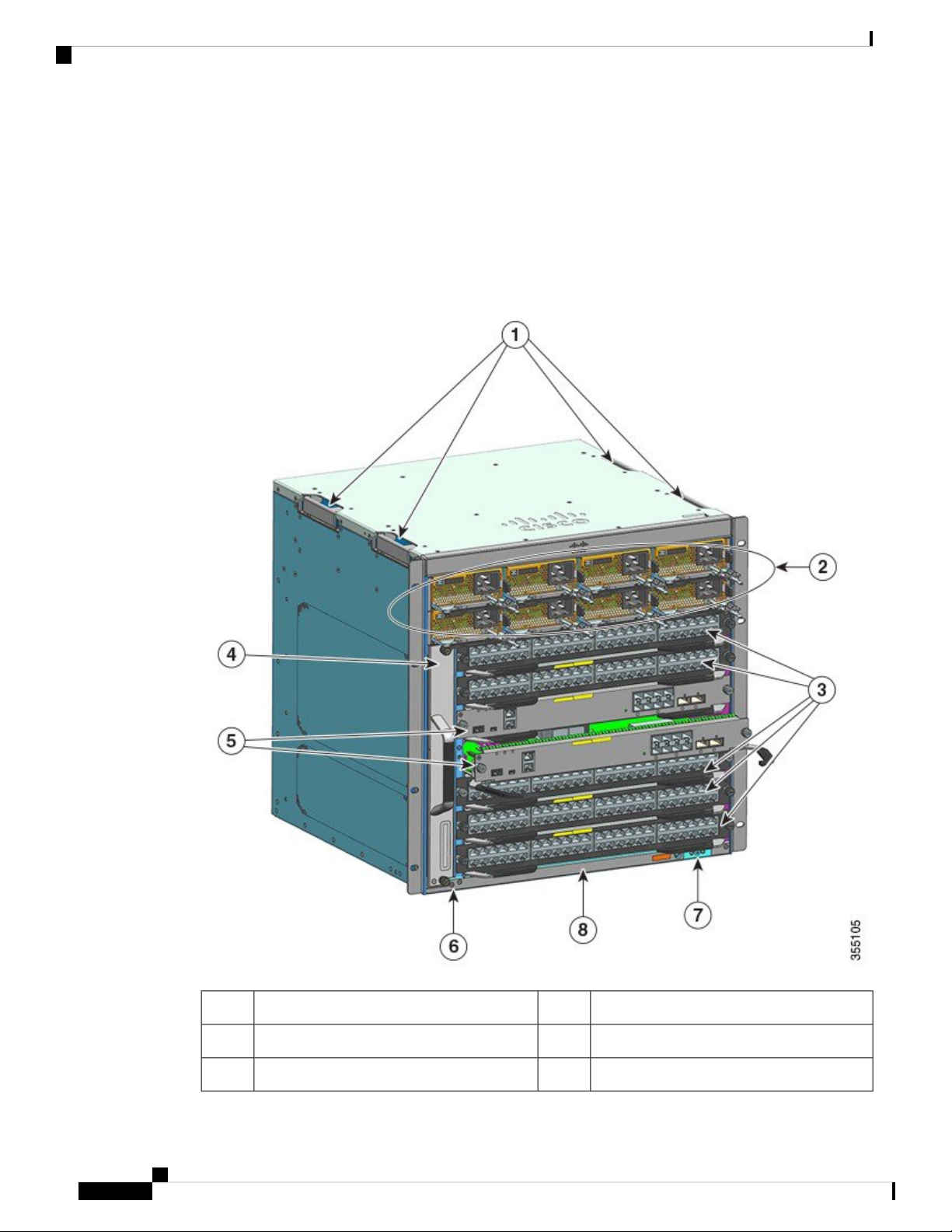
The Catalyst 9407R Switch is a seven-slot modular chassis, with two redundant supervisor module slots, five
switching module slots with up to 240 front panel ports, one non-redundant fan tray assembly, and a provision
to accommodate up to eight power supply modules.
Front View of the Catalyst 9407R Switch
The figure shows a front view of the chassis, with the major components identified:
Product Overview
Supervisor module slots (3 and 4)5Chassis handholds1
Chassis Radio Frequency ID (RFID)6Power supply modules2
System ground7Switching module slots (1,2, 5,6, and 7)3
Cisco Catalyst 9400 Series Switches Hardware Installation Guide
8
Page 15

Product Overview
Catalyst 9407R Switch
Chassis model number8Fan tray assembly4
Rear View of the Catalyst 9407R Switch
The figure shows a rear view of the chassis, with the major components identified:
Table 2: Catalyst 9407R Switch Features
Product ID
Chassis
2Access to remove fan tray from the rear1
Blue beacon LED on the rear panel of the fan
tray (always matches the blue beacon on the
front panel of the fan tray)
DescriptionFeature
C9407R—Cisco Catalyst 9400 Series 7 Slot Chassis
C9407R= (Spare)
Has seven horizontal slots. Slots are numbered 1 (top)
to 7 (bottom)
Cisco Catalyst 9400 Series Switches Hardware Installation Guide
9
Page 16
Catalyst 9407R Switch
Product Overview
DescriptionFeature
Supervisor modules
Supports 1+1 supervisor module redundancy for
integrated resiliency. Supported model number:
Cisco Catalyst 9400 Series Supervisor 1 Module
(C9400-SUP-1) and the module spare C9400-SUP-1=
Cisco Catalyst 9400 Series Supervisor 1XL Module
( C9400-SUP-1XL) and the module spare
C9400-SUP-1XL=
Cisco Catalyst 9400 Series Supervisor 1XL25G
Module (C9400-SUP-1XL-Y) and the module spare
C9400-SUP-1XL-Y=
Supervisor modules:
• Must be installed in slots numbered 3 and 4 only.
• Have minimum software release version
requirements. Refer to your software release
notes for this information.
See Cisco Catalyst 9400 Series Supervisor Module
Installation Note
Cisco Catalyst 9400 Series Switches Hardware Installation Guide
10
Page 17

Product Overview
Catalyst 9407R Switch
DescriptionFeature
Switching modules
Accomodates five line cards. Supported model
numbers:
• Cisco Catalyst 9400 Series 48-Port UPOE
10/100/1000 Module (C9400-LC-48U) and the
module spare (C9400-LC-48U=)
• Cisco Catalyst 9400 Series 48-Port 10/100/1000
Module (C9400-LC-48T) and the module spare
(C9400-LC-48T=)
• Cisco Catalyst 9400 Series 24-Port SFP/SFP+
Module (C9400-LC-24XS) and the module spare
(C9400-LC-24XS=).
• Cisco Catalyst 9400 Series 48-Port UPOE
Multigigabit Module (C9400-LC-48UX) and the
module spare (C9400-LC-48UX=).
• Cisco Catalyst 9400 Series 48-Port SFP Module
(C9400-LC-48S) and the module spare
(C9400-LC-48S=)
• Cisco Catalyst 9400 Series 24-Port SFP Module
(C9400-LC-24S) and the module spare
(C9400-LC-24S=)
Fan tray assembly
Power supplies
• Cisco Catalyst 9400 Series 48-Port Gigabit
Ethernet POE/POE+ Module (C9400-LC-48P)
and the module spare (C9400-LC-48P=)
See Cisco Catalyst 9400 Series Switching Module
Installation Note
The switch supports a single front and rear serviceable
and hot-swappable fan tray with 12 fans.
Supported model number—C9407-FAN and
C9407-FAN= (Spare)
See Fan Tray Assembly Overview, on page 17 and
Fan Tray LEDs, on page 133
The chasis supports up to eight AC-input power
supply modules.
Supported model number—C9400-PWR-3200AC
and C9400-PWR-3200AC= (Spare).
See Power Supply Module Overview, on page 20 and
Power Supply LEDs, on page 134
Cisco Catalyst 9400 Series Switches Hardware Installation Guide
11
Page 18
Catalyst 9410R Switch
Product Overview
DescriptionFeature
Backplane
RFID Tag
Catalyst 9410R Switch
The Catalyst 9410R Switch is a ten-slot modular chassis, with two redundant supervisor module slots, eight
switching module slots with up to 384 1-Gigabit Ethernet front panel ports, one non-redundant fan tray
assembly, and a provision to accommodate up to eight power supply modules.
120 Gbps backplane bandwidth for each payload
module slot.
Each line card slot supports up to 32 channels
connected to each supervisor module slot.
The chassis has a built-in, front-facing, passive RFID
tag that uses Ultra High Frequency (UHF) RFID
technology and requires an RFID reader with
compatible software. It provides auto-identification
capabilities for asset management and tracking. The
RFID tags are compatible with the Generation 2 GS1
EPC Global Standard and are ISO 18000-6C
compliant. They operate in the 860- to 960-MHz UHF
band. For more information, see Radio Frequency
Identification (RFID on Cisco Catalyst 9000 Family
Switches).
Front View of the Catalyst 9410R Switch
The figure shows a front view of the chassis, with the major components identified:
Cisco Catalyst 9400 Series Switches Hardware Installation Guide
12
Page 19

Product Overview
Catalyst 9410R Switch
Supervisor module slots (5 and 6)5Chassis handholds1
Chassis Radio Frequency ID (RFID)6Power supply modules2
3
System ground7Switching module slots (1,2, 3, 4, 7, 8, 9 and
10)
Chassis model number8Fan tray assembly4
Cisco Catalyst 9400 Series Switches Hardware Installation Guide
13
Page 20
Catalyst 9410R Switch
Product Overview
Rear View of the Catalyst 9410R Switch
The figure shows a rear view of the chassis, with the major components identified:
2Access to remove fan tray from the rear1
Blue beacon LED on the rear of the fan tray
(always matches the blue beacon on the front
of the fan tray)
Table 3: Catalyst 9410R Switch Features
DescriptionFeature
Product ID
C9410R—Cisco Catalyst 9400 Series 10 Slot Chassis
C9410R= (Spare)
Cisco Catalyst 9400 Series Switches Hardware Installation Guide
14
Page 21

Product Overview
Catalyst 9410R Switch
DescriptionFeature
Chassis
Supervisor modules
Has ten horizontal slots. Slots are numbered 1 (top)
to 10 (bottom)
Supports 1+1 supervisor module redundancy for
integrated resiliency. Supported model number:
Cisco Catalyst 9400 Series Supervisor 1 Module
(C9400-SUP-1) and the module spare C9400-SUP-1=
Cisco Catalyst 9400 Series Supervisor 1XL Module
(C9400-SUP-1XL) and the module spare
C9400-SUP-1XL=
Cisco Catalyst 9400 Series Supervisor 1XL25G
Module (C9400-SUP-1XL-Y) and the module spare
C9400-SUP-1XL-Y=
Supervisor modules:
• Must be installed in slots numbered 5 and 6 only.
• Have minimum software release version
requirements. Refer to your software release
notes for this information.
See Cisco Catalyst 9400 Series Supervisor Module
Installation Note
Cisco Catalyst 9400 Series Switches Hardware Installation Guide
15
Page 22

Catalyst 9410R Switch
Product Overview
DescriptionFeature
Switching modules
Accomodates eight line cards. Supported model
numbers:
• Cisco Catalyst 9400 Series 48-Port UPOE
10/100/1000 Module (C9400-LC-48U) and the
module spare (C9400-LC-48U=)
• Cisco Catalyst 9400 Series 48-Port 10/100/1000
Module (C9400-LC-48T) and the module spare
(C9400-LC-48T=)
• Cisco Catalyst 9400 Series 24-Port SFP/SFP+
10 Gigabit Ethernet Module (C9400-LC-24XS)
and the module spare (C9400-LC-24XS=).
• Cisco Catalyst 9400 Series 48-Port UPOE
Multigigabit Ethernet Module (C9400-LC-48UX)
and the module spare (C9400-LC-48UX=).
• Cisco Catalyst 9400 Series 48-Port SFP Module
(C9400-LC-48S) and the module spare
(C9400-LC-48S=)
• Cisco Catalyst 9400 Series 24-Port SFP Module
(C9400-LC-24S) and the module spare
(C9400-LC-24S=)
Fan tray assembly
Power supplies
Backplane
• Cisco Catalyst 9400 Series 48-Port Gigabit
Ethernet POE/POE+ Module (C9400-LC-48P)
and the module spare (C9400-LC-48P=)
See Cisco Catalyst 9400 Series Switching Module
Installation Note
The switch supports a single front and rear serviceable
and hot-swappable fan tray with 16 fans.
Supported model number— C9410-FAN and
C9410-FAN= (Spare)
See Fan Tray Assembly Overview, on page 17 and
Fan Tray LEDs, on page 133
The chasis supports up to eight AC-input power
supply modules.
Supported model number—C9400-PWR-3200AC
and C9400-PWR-3200AC=(Spare).
See Power Supply Module Overview, on page 20 and
Power Supply LEDs, on page 134
80 Gbps backplane bandwidth for each payload
module slot.
Cisco Catalyst 9400 Series Switches Hardware Installation Guide
16
Page 23
Product Overview
Fan Tray Assembly
DescriptionFeature
RFID Tag
Fan Tray Assembly
Fan Tray Assembly Overview
A Cisco Catalyst 9400 Series fan tray assembly—
• Is composed of a fan tray and an adapter that is attached to the fan tray. It is responsible for cooling the
entire chassis and interfacing with environmental monitors to trigger alarms when conditions exceed
thresholds.
The chassis has a built-in, front-facing, passive RFID
tag that uses Ultra High Frequency (UHF) RFID
technology and requires an RFID reader with
compatible software. It provides auto-identification
capabilities for asset management and tracking. The
RFID tags are compatible with the Generation 2 GS1
EPC Global Standard and are ISO 18000-6C
compliant. They operate in the 860- to 960-MHz UHF
band. For more information, see Radio Frequency
Identification (RFID on Cisco Catalyst 9000 Family
Switches).
• Has side-to-side airflow for balanced airflow across the inserted cards. When facing the front of the
chassis, airflow direction is right to left.
• Can be installed and removed from the front and the rear.
• Has a built-in, front-facing, passive RFID tag that uses Ultra High Frequency (UHF) RFID technology
and requires an RFID reader with compatible software. It provides auto-identification capabilities for
asset management and tracking. The RFID tags are compatible with the Generation 2 GS1 EPC Global
Standard and are ISO 18000-6C compliant. They operate in the 860- to 960-MHz UHF band. For more
information, see Radio Frequency Identification (RFID) on Cisco Catalyst 9000 Family Switches.
• Is chassis-specific. (Add = to the model number for spares)
• Model number C9404-FAN for the Catalyst 9404R Switch.
This model has eight individual fans (two rows of four each). It supports a minimum airflow of 640
cubic feet per minute (CFM) at 100 percent fan throttle.
• Model number C9407-FAN for the Catalyst 9407R Switch.
This model has 12 individual fans (three rows). It supports a minimum airflow of 960 cubic feet
per minute (CFM) at 100 percent fan throttle.
• Model number C9410-FAN for the Catalyst 9410R Switch.
This model has 16 individual fans (four rows). It supports a minimum airflow of 1190 CFM at 100
percent fan throttle.
Cisco Catalyst 9400 Series Switches Hardware Installation Guide
17
Page 24
Operation
Product Overview
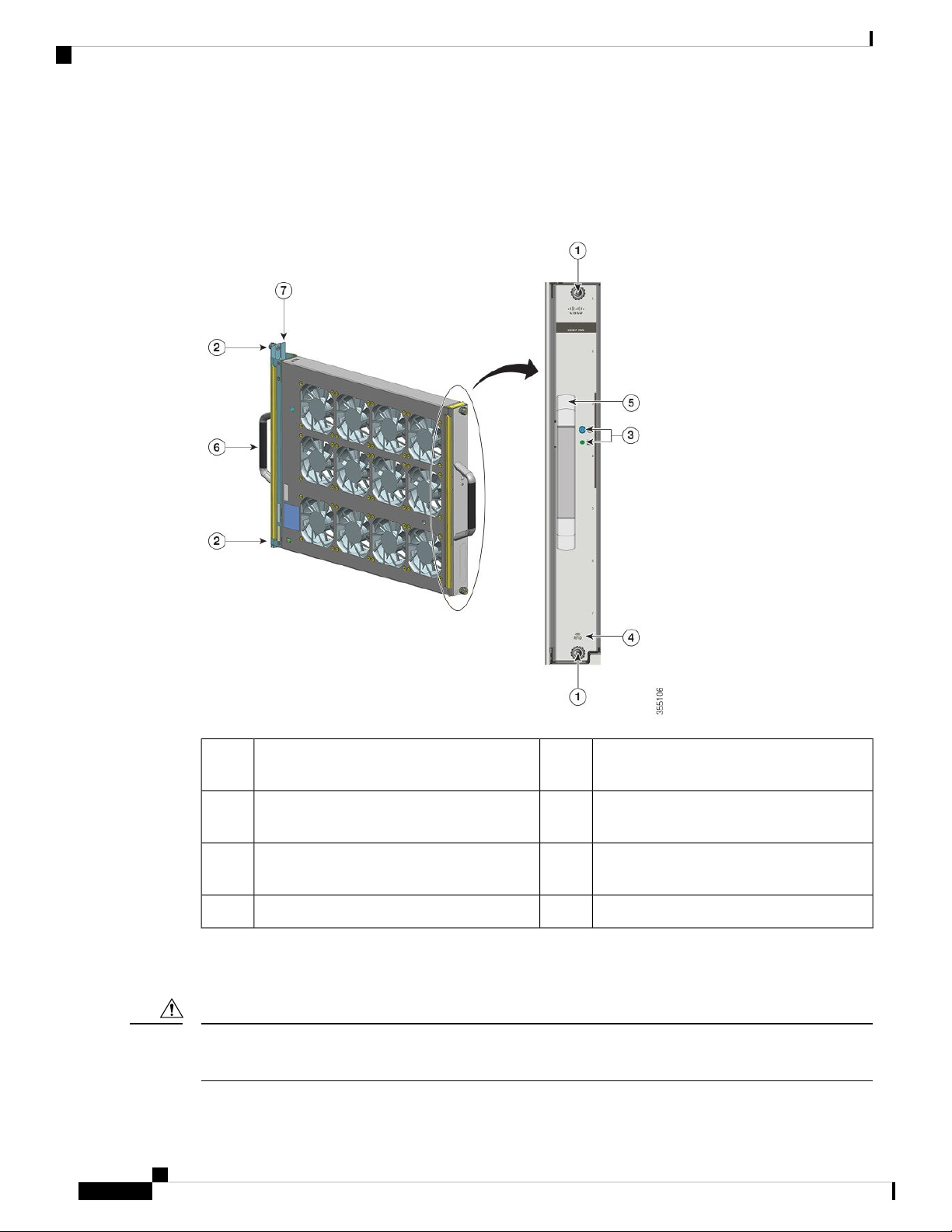
The following figure shows the C9407-FAN with the major components identified. The C9410-FAN has the
same features, and in addition, a fourth row of fans. The C9404-FAN has the same features but has only two
rows of fans.
Figure 1: Fan Tray Assembly
Operation
Caution
18
1
Front fan tray handle.5Captive installation screws on the front of the
fan tray.
2
Rear fan tray handle6Captive installation screws on the rear of the
fan tray.
3
Fan tray adapter7LEDs on the front panel. (The rear blue
beacon LED is not visible in this image)
--Fan tray RFID4
Do not operate the system if the fan tray assembly is removed or if it is not functioning properly. An
overtemperature condition can cause severe equipment damage or an unscheduled system shutdown.
Cisco Catalyst 9400 Series Switches Hardware Installation Guide
Page 25

Product Overview
Depending on the ambient conditions, the system optimises the fan-speed for temperature and pressure and
maintains the minimum fan speeds and temperatures that the chassis requires. Accordingly, the fan tray's
internal controller operates in a normal mode and a Network Equipment-Building System mode (NEBS mode).
High Availability
To ensure high availability, the system is designed to respond to fan failures by either minimising impact or
by compensating and operating at a worst case scenario specification.
High Availability
• In the normal mode—the controller optimizes fan-speed for temperature and pressure.
• In the NEBS mode—the controller responds more aggressively, to maintain proper cooling for installations
with high airflow impedance. When the fan tray operates in this mode, there may be increased noise
levels due to increased fan speeds.
You can also manually set the fan tray to operate in the NEBS mode.
• If a single fan fails, the remaining fans in the row compensate with increased speed.
• If two or more fans fail, the entire fan tray operates at full speed after one minute. Further, the fan tray
must be replaced. The individual fans are not field replaceable, you must replace the fan tray.
• If the temperature sensor fails or communication with the temperature sensor fails, the worst case operating
temperature is assumed.
• If the pressure sensor fails or communication with the pressure sensor fails, the worst case operating
pressure is assumed.
Thresholds, Alarms, and Abnormal Acoustic Conditions
Under normal operating conditions, when none of the temperature alarms have been triggered, hardware
controls fan speed. If any of the system temperature alarms are triggered, software takes fan speed control
from hardware. Refer to the System Management section of the software configuration guide for more
information.
When the fan tray operates at full speed, increased noise levels may be expected. The fan tray may operate
at full speed in these circumstances:
• If the fan tray is not installed correctly
• When operating in the NEBS mode
• If two or more fans have failed
• If the STATUS LED remains red for more than one minute
• If there is a hardware failure
• If the software watchdog timer is triggered
Cisco Catalyst 9400 Series Switches Hardware Installation Guide
19
Page 26

Power Supply Module
Power Supply Module
Power Supply Module Overview
Applicable model numbers:
• C9400-PWR-3200AC and spare C9400-PWR-3200AC=
• C9400-PWR-2100AC and spare C9400-PWR-2100AC=
Note
Unless otherwise indicated, power supply information in this document applies to all available power supply
modules.
The chassis supports one to eight field-replaceable, AC-input power supply modules, each with its own on/
off rocker switch.
Product Overview
Features
• Self-cooling, with a minimum airflow of 17 cubic feet per minute (CFM) at 100 percent load.
• Provides a regulated 55 VDC PoE compliant main output and 3.3 VDC standby output.
• Supports only single-phase source AC. Source AC can be out of phase between multiple power supplies
or multiple AC-power plugs on the same power supply because all AC power supply inputs are isolated
• Has a release latch and cord-retention mechanism on the front panel of the module, to avoid accidental
removal of the module or the attached power cord.
• Supports redundant and combined configuration modes. A single (non-redundant) or a dual (redundant)
power supply configuration, can support the following loads:
Input Voltage (VAC)
• Has a built-in, front-facing, passive RFID tag that uses Ultra High Frequency (UHF) RFID technology
and requires an RFID reader with compatible software. It provides auto-identification capabilities for
asset management and tracking. The RFID tags are compatible with the Generation 2 GS1 EPC Global
Standard and are ISO 18000-6C compliant. They operate in the 860- to 960-MHz UHF band. For more
information, see Radio Frequency Identification (RFID) on Cisco Catalyst 9000 Family Switches.
Output Power with
C9400-PWR-3200AC (In Watts)
Output Power with
C9400-PWR-2100AC
2112W3200W200VAC
950W1570W100VAC
Cisco Catalyst 9400 Series Switches Hardware Installation Guide
20
Page 27

Product Overview
Power Supply Module Overview
Figure 2: C9400-PWR-3200AC
Operation
The power supply connectors distribute power as follows:
Cisco Catalyst 9400 Series Switches Hardware Installation Guide
Power cord retainer5On/ Off rocker switch1
Airflow intake6LEDs.2
Airflow exhaust7Power supply module RFID3
--Release latch4
C9400-PWR-2100ACC9400-PWR-3200ACModule
Maximum of 20A at 55VDCMaximum of 20A at 55VDCSupervisor Module (Main Output)
Maximum of 120A at 55VDCMaximum of 120A at 55VDCSwitching Module (Main Output)
21
Page 28

Power Supply Modes
Backplane
(Standby Output)
Power Supply Modes
Cisco Catalyst 9400 Series Switches offer redundant and combined configuration modes for power supplies.
The number of power supply modules installed and the system load determine the power-level that the system
expects to draw from each power supply module and consequently, the power supply mode that will be suitable.
For system power budgeting estimates and to determine power supply requirements for a specific Power over
Ethernet (PoE) configuration, use the Cisco Power Calculator.
To configure a power supply mode, enter the power redundancy-mode command in global configuration
mode. If you do not configure a mode, the default mode applies.
Product Overview
C9400-PWR-2100ACC9400-PWR-3200ACModule
3.3VDC3.3VDCFan Tray, Supervisor Module,
Warning
Combined Mode
This is the default power supply mode.
The system operates on one to eight power supply modules. The power available to the system is the sum of
power outputs of all the power supply modules in the chassis. All available power supply modules are active
and sharing power, and can operate at up to 100 percent capacity.
In case of failure in the combined mode, each operational power supply increases its output. If the output
power does not meet system requirements and the power supply autolc shutdown command is disabled,
then all the operational power supply modules may be overloaded and go into overcurrent shutdown. All
system power is then lost.
Redundant Mode
In a redundant configuration, a given power supply module can either be active, or in standby mode and switch
to active when required.
• An active power supply module is powered on, and provides output power. All active modules in a
chassis always attempt to share the load.
• A standby power supply module is powered on, but asleep. When in this mode, the power supply module’s
OUTPUT LED is blinking green.
To ensure high availability, the system is designed to respond to failures as follows:
• If all available power supply modules are active, operational power supplies continue to share current
equally. Note that the load on the available power supplies will have increased.
• If standby power supply modules are available, the minimum number of power supply modules needed
to power the load, switch to active.
You can configure an n+1 or an n+n redundant mode.
Cisco Catalyst 9400 Series Switches Hardware Installation Guide
22
Page 29

Product Overview
Installation Considerations - Power Supply Modules of Different Capacities
N+1 Redundant Mode
N is the number of active power supply modules and can be one to seven power supply modules. +1 is the
power supply module reserved for redundancy and must be configured as the standby module (power
redundancy-mode command).
The default standby power supply slot on a seven-slot or a ten-slot chassis is 8. The default standby power
supply slot on a four-slot chassis is 4. To designate a different slot as standby, enter the power
redundancy-mode command.
N+N Redundant Mode
N number of power supplies are active, and n number of power supply modules are configured as standby
(power redundancy-mode command).
For detailed software configuration information, see the System Management → Environmental Monitoring
and Power Management section of the software configuration guide for the required release.
Installation Considerations - Power Supply Modules of Different Capacities
You can install power supplies of different capacities in a Cisco Catalyst 9400 Series chassis.
If you do, and you use the default power supply mode, which the combined mode, there are no additional
factors to consider. However, in the redundant mode (n+1 and n+n), you must observe the guidelines outlined
here.
Note
While the installation of power supplies of different capacities in the same chassis is supported, it is not an
optimal use of total system power in a redundant mode.
N+1 Redundant Mode with Power Supplies of Different Capacities
The power supply module with the highest wattage or capacity must be configured as the standby.
N+N Redundant Mode with Power Supplies of Different Capacities
At the time of switch over to standby power, the total standby output power must be greater than or equal to
the total active output power at the time of a switch over (total standby output power >= total active output
power).
Cisco Catalyst 9400 Series Switches Hardware Installation Guide
23
Page 30

Installation Considerations - Power Supply Modules of Different Capacities
Product Overview
Cisco Catalyst 9400 Series Switches Hardware Installation Guide
24
Page 31

Preparing for Installation
• Safety Warnings, on page 25
• Site Requirements, on page 26
• Power Requirements, on page 35
• Cabling Requirements, on page 36
• Rack-Mounting Guidelines, on page 36
• Site Preparation Checklist, on page 38
Safety Warnings
Safety warnings appear throughout this publication in procedures that may harm you if you perform them
incorrectly. A warning symbol precedes each warning statement. The warnings below are general warnings
that are applicable to the entire publication.
CHAPTER 3
Warning
Warning
Warning
Warning
Warning
Class 1 laser product. Statement 1008
Only trained and qualified personnel should be allowed to install, replace, or service this equipment. Statement
1030
Hazardous voltage or energy is present on the backplane when the system is operating. Use caution when
servicing. Statement 1034
Invisible laser radiation may be emitted from disconnected fibers or connectors. Do not stare into beams or
view directly with optical instruments. Statement 1051
Class 1M laser radiation when open. Do not view directly with optical instruments. Statement 1053
Cisco Catalyst 9400 Series Switches Hardware Installation Guide
25
Page 32

Site Requirements
Preparing for Installation
Warning
Warning
Class I (CDRH) and Class 1M (IEC) laser products. Statement 1055
Invisible laser radiation may be emitted from the end of the unterminated fiber cable or connector. Do not
view directly with optical instruments. Viewing the laser output with certain optical instruments (for example,
eye loupes, magnifiers, and microscopes) within a distance of 100 mm may pose an eye hazard. Statement
1056
Site Requirements
Planning a proper location for the switch and layout of the equipment rack or wiring closet is essential for
successful system operation. These sections describe some of the basic site requirements that you should be
aware of as you prepare to install your switch, including the following:
• Environmental factors can adversely affect the performance and longevity of your system.
• Install the switch in an enclosed, secure area, ensuring that only qualified personnel have access to the
switch and control of the environment.
• Equipment that is placed too closely together or that is inadequately ventilated may cause system
over-temperature conditions, leading to premature component failure.
• Poor equipment placement can make chassis panels inaccessible and difficult to maintain.
• The switch requires a dry, clean, well-ventilated, and air-conditioned environment.
• To ensure normal operation, maintain ambient airflow. If the airflow is blocked or restricted, or if the
intake air is too warm, an over-temperature condition may occur. The switch environmental monitor may
then shut down the system to protect the system components.
• Multiple switches can be rack mounted with little or no clearance above and below the chassis. However,
when mounting a switch in a rack with other equipment, or when placing it on the floor near other
equipment, ensure that the exhaust from other equipment does not blow into the air intake vent of the
switch chassis.
Cisco Catalyst 9400 Series Switches Hardware Installation Guide
26
Page 33

Preparing for Installation
Temperature
Temperature
Temperature extremes may cause a system to operate at reduced efficiency and cause a variety of problems,
including premature aging and failure of chips, and failure of mechanical devices. Extreme temperature
fluctuations may also cause chips to become loose in their sockets. Observe the following guidelines:
• Ensure that the system is operating in an environment that is—
• 27 to 109 °F ( -5 to +45 °C) up to 6000 feet (1800m)
• 27 to 104 °F (-5 to +40 °C) up to 10000 feet (3000m)
• Ensure that the chassis has adequate ventilation.
• Do not place the chassis within a closed-in wall unit or on top of cloth, which can act as insulation.
• Do not place the chassis where it will receive direct sunlight, particularly in the afternoon.
• Do not place the chassis next to a heat source of any kind, including heating vents.
• Do not operate the system if the fan assembly is removed or if it is not functioning properly. An
overtemperature condition can cause severe equipment damage or an unscheduled system shutdown.
Air Flow
• Adequate ventilation is particularly important at high altitudes. Make sure that all the slots and openings
on the system remain unobstructed, especially the fan vent on the chassis.
• Clean the installation site at regular intervals to avoid buildup of dust and debris, which may cause a
system to overheat.
• If system is exposed to abnormally low temperatures, allow a two hour warm up period, in ambient
temperature no lower than 32°F (0 °C) before turning on.
Failure to observe these guidelines may damage the chassis' internal components.
The switch is designed to be installed in an environment where there is a sufficient volume of air available to
cool the supervisor engines, modules, and power supplies. If there are any constraints with regard to the free
flow of air through the chassis, or if the ambient air temperature is elevated, the switch environmental monitor
may then shut down the system to protect the system components.
To maintain proper air circulation through the switch chassis, we recommend that you maintain a minimum
space of 6 inches (15 cm) between a wall and the chassis and power supply unit air intakes or a wall and the
chassis and power supply unit hot air exhausts. In situations where the switch chassis are installed in adjacent
racks, you should allow a minimum space of 12 inches (30.5 cm) between the air intake of one chassis and
the hot air exhaust of another chassis. Failure to maintain adequate spacing between chassis may cause the
switch chassis that is drawing in the hot exhaust air to overheat and fail.
Figure 3: Air Flow Direction - Cisco Catalyst 9400 Series Switches
The figure shows the chassis and power supply air flow directions in a Catalyst 9407R Switch. The same air
flow direction applies to all Cisco Catalyst 9400 Series Switches.
Cisco Catalyst 9400 Series Switches Hardware Installation Guide
27
Page 34

Air Flow
Preparing for Installation
Power supply air intake3Chassis air intake1
Power supply air exhaust4Chassis air exhaust2
If you are installing your switch in an enclosed or partially enclosed rack, we strongly recommend that you
verify that your site meets the following guidelines:
• Verify that there is a minimum of 6 inches (15 cm) of clearance between the sides, front, and back of
any enclosure, and both the chassis air intake grill and the chassis air exhaust grill along with the power
supply unit intakes and exhausts. The upright columns of a relay rack may be located less than the
recommended side spacing provided there are substantial cutouts, holes, or vents in the structure to allow
adequate air flow through the chassis.
• Verify that the ambient air temperature within the enclosed or partially enclosed rack is within the chassis
operating temperature limits. After installing the chassis in the rack, power up the chassis and allow the
chassis temperature to stabilize (approximately 2 hours).
Measure the ambient air temperature at the chassis air intake grill by positioning an external temperature
probe 1 inch (2.5 cm) away from the chassis left side, and centered on the chassis both horizontally and
vertically.
Measure the ambient air temperature at the power supply unit air intake grill by positioning an external
temperature probe 1 inch (2.5 cm) away from the chassis front, centered on the power supply unit section
located above the card slots.
• If the ambient intake air temperature is less than 109°F (45°C) at altitudes of 6,000 feet and below,
the rack meets the intake air temperature criterion. At altitudes above that threshold and up to 10,000
feet (3000 m), the air intake should not exceed 104°F (40°C).
Cisco Catalyst 9400 Series Switches Hardware Installation Guide
28
Page 35

Preparing for Installation
Humidity
• If the ambient intake air temperature exceeds this recommendation, the system may experience
minor temperature alarms and increase fan speeds in response.
• If the ambient intake air temperature equals or is greater than 131°F (55°C), the system may
experience a major temperature alarm with maximum fan speeds in response. If ambient temperature
continues to increase, system will respond with protective shut down.
• Plan ahead. A switch that is currently installed in an enclosed or partially enclosed rack might meet
ambient air temperature and air flow requirements at present. However, if you add more chassis to the
rack or more modules to a chassis in the rack, the additional heat generated might cause the ambient air
temperature at the chassis or power supply unit inlets to exceed recommended conditions which may
trigger thermal alarms.
If installation conditions for inlet temperature and airflow are marginal or not fully met, activate the fan
tray’s NEBS mode, which has more aggressive programming to address restricted spacing and elevated
ambient temperatures. This should result in reduced thermal alarms along with greater acoustic noise
and increased power consumption associated with higher fan speeds.
Humidity
High-humidity conditions may cause moisture to enter the system, and cause corrosion of internal components
and degradation of properties such as electrical resistance, thermal conductivity, physical strength, and size.
Extreme moisture buildup inside the system may result in electrical short circuit, which may cause serious
damage to the system. Each system is rated for storage and operation in 10 to 95 percent relative humidity,
non-condensing with a humidity gradation of 10 percent per hour. Buildings in which climate is controlled
by air-conditioning in the warmer months and by heat during the colder months usually maintain an acceptable
level of humidity for system equipment. However, if a system is located in an unusually humid location, a
dehumidifier should be used to maintain the humidity within an acceptable range.
Altitude
Operating a system at high altitude (low pressure) reduces the efficiency of forced and convection cooling
and may result in electrical problems related to arcing and corona effects. This condition may also cause sealed
components with internal pressure, such as electrolytic capacitors, to fail or perform at reduced efficiency.
Dust and Particles
Fans cool power supplies and system components by drawing in room-temperature air and exhausting heated
air out through various openings in the chassis. However, fans also ingest dust and other particles, causing
contaminant buildup in the system and increased internal chassis temperature. A clean operating environment
can greatly reduce the negative effects of dust and other particles, which act as insulators and interfere with
the mechanical components in the system. The standards listed below provide guidelines for acceptable
working environments and acceptable levels of suspended particulate matter:
• National Electrical Manufacturers Association (NEMA) Type 1
• International Electrotechnical Commission (IEC) IP-20
Cisco Catalyst 9400 Series Switches Hardware Installation Guide
29
Page 36

Corrosion
Corrosion
Corrosion of system connectors is a gradual process that may eventually lead to intermittent failures of electrical
circuits. The oil from a person’s fingers or prolonged exposure to high temperature or humidity may corrode
the gold-plated edge connectors and pin connectors on various components in the system. To prevent corrosion,
avoid touching contacts on boards and cards, and protect the system from extreme temperatures and moist,
salty environments.
EMI and Radio Frequency Interference
Electro-Magnetic interference (EMI) and radio frequency interference (RFI) from a system can adversely
affect devices such as radio and television (TV) receivers operating near the system. Radio frequencies
emanating from a system can also interfere with cordless and low-power telephones. Conversely, RFI from
high-power telephones can cause spurious characters to appear on the system monitor. RFI is defined as any
EMI with a frequency above 10 kilohertz (kHz). This type of interference can travel from the system to other
devices through the power cable and power source, or through the air in the form of transmitted radio waves.
The Federal Communications Commission (FCC) publishes specific regulations to limit the amount of EMI
and RFI emitted by computing equipment. Each system meets these FCC regulations. To reduce the possibility
of EMI and RFI, follow these guidelines:
Preparing for Installation
• Always operate the system with the chassis covers installed.
• Ensure that all chassis slots are covered by a metal filler bracket and that an unused power supply bay
has a metal cover plate installed.
• Ensure that the screws on all peripheral cable connectors are securely fastened to their corresponding
connectors on the back of the chassis.
• Always use shielded cables with metal connector shells for attaching peripherals to the system.
When wires are run for any significant distance in an electromagnetic field, interference can occur between
the field and the signals on the wires. This fact has two implications for the construction of plant wiring:
• Bad wiring practice can result in radio interference emanating from the plant wiring.
• Strong EMI, especially when it is caused by lightning or radio transmitters, can destroy the signal drivers
and receivers in the chassis, and even create an electrical hazard by conducting power surges through
lines into equipment.
Note
To predict and provide a remedy for strong EMI, consult experts in RFI.
If you use twisted-pair cable in your plant wiring with a good distribution of grounding conductors, the plant
wiring is unlikely to emit radio interference. If you exceed the recommended distances, use a high-quality
twisted-pair cable with one ground conductor for each data signal when applicable.
30
Caution
Category 5e, Category 6, and Category 6a cables can store large levels of static electricity because of the
dielectric properties of the materials used in their construction. Always ground the cables (especially in new
cable runs) to a suitable and safe earth ground before connecting them to the module.
Cisco Catalyst 9400 Series Switches Hardware Installation Guide
Page 37

Preparing for Installation
If the wires exceed the recommended distances, or if wires pass between buildings, give special consideration
to the effect of a lightning strike in your vicinity. The electromagnetic pulse caused by lightning or other
high-energy phenomena can easily couple enough energy into unshielded conductors to destroy electronic
devices. If you have had problems of this sort in the past, you may want to consult experts in electrical surge
suppression and shielding.
Shock and Vibration
The switch has been shock- and vibration-tested for operating ranges, handling, and earthquake standards to
NEBS (Zone 4 per GR-63-Core). These tests have been conducted in earthquake environment and criteria,
office vibration and criteria, transportation vibration and criteria, and packaged equipment shock.
Power Source Interruptions
Systems are especially sensitive to variations in voltage supplied by the AC power source. Overvoltage,
undervoltage, and transients (or spikes) can erase data from memory or even cause components to fail. To
protect against these types of problems, power cables should always be properly grounded. Also, place the
system on a dedicated power circuit (rather than sharing a circuit with other heavy electrical equipment). In
general, do not allow the system to share a circuit with any of the following:
Shock and Vibration
• Copy machines
• Air conditioners
• Vacuum cleaners
• Space heaters
• Power tools
• Teletype machines
• Laser printers
• Facsimile machines
• Any other motorized equipment
Besides these appliances, the greatest threats to a system's power supply are surges or blackouts that are caused
by electrical storms. Whenever possible, turn off the system and peripherals, if any, and unplug them from
their power sources during thunderstorms. If a blackout occurs—even a temporary one—while the system is
turned on, turn off the system immediately and disconnect it from the electrical outlet. Leaving the system on
may cause problems when the power is restored; all other appliances left on in the area may create large
voltage spikes that may damage the system.
System Grounding
You must install a system ground as part of the chassis installation process. Chassis installations that rely only
on the AC third-prong ground are insufficient to adequately ground the systems.
Proper grounding practices ensure that the buildings and the installed equipment within them have
low-impedance connections and low-voltage differentials between chassis. When you install a system ground,
Cisco Catalyst 9400 Series Switches Hardware Installation Guide
31
Page 38

System Grounding
Preparing for Installation
you reduce or prevent shock hazards, chances of equipment damage due to transients, and the potential for
data corruption.
Without proper and complete system grounding, you run the risk of increased component damage due to ESD.
Additionally, you have a greatly increased chance of data corruption, system lockup, and frequent system
reboot situations by not using a system ground.
Caution
Installations that rely solely on system grounding that uses only an AC third-prong ground run a substantially
greater risk of equipment problems and data corruption than those installations that use both the AC third-prong
ground and a properly installed system ground.
The following table lists some general grounding practice guidelines.
Table 4: Grounding Practice Guidelines
Environment
Grounding RecommendationsElectromagnetic Noise
Severity Level
HighCommercial building is subjected to
direct lightning strikes.
For example, some places in the United
States, such as Florida, are prone to
more lightning strikes than other areas.
All lightning protection devices must be
installed in strict accordance with
manufacturer recommendations.
Conductors carrying lightning current
should be spaced away from power and
data lines in accordance with applicable
recommendations and codes. Best
grounding practices must be closely
followed.
HighCommercial building is located in an
area where lightning storms occur
Best grounding practices must be closely
followed.
frequently, but is not prone to direct
lightning strikes.
Medium to HighCommercial building contains a mix
of information technology equipment
Best grounding practices must be closely
followed.
and industrial equipment, such as
welding.
MediumExisting commercial building is not
subject to natural environmental noise
or man-made industrial noise. This
building contains a standard office
environment. This installation has a
history of malfunction due to
Best grounding practices must be closely
followed. Determine source and cause of
noise if possible, and mitigate as closely as
possible at the noise source or reduce
coupling from the noise source to the
victim equipment.
electromagnetic noise.
Cisco Catalyst 9400 Series Switches Hardware Installation Guide
32
Page 39

Preparing for Installation
Maintaining Safety with Electricity
Environment
Grounding RecommendationsElectromagnetic Noise
Severity Level
LowNew commercial building is not subject
to natural environmental noise or
man-made industrial noise. This
building contains a standard office
environment.
Best grounding practices should be
followed as closely as possible.
Electromagnetic noise problems are not
anticipated, but installing a best-practice
grounding system in a new building is often
the least expensive route, and the best way
to plan for the future.
LowExisting commercial building is not
subject to natural environmental noise
or man-made industrial noise. This
building contains a standard office
environment.
Note
In all situations, grounding practices must comply with Section 250 of the National Electric Code (NEC)
Best grounding practices should be
followed as much as possible.
Electromagnetic noise problems are not
anticipated, but installing a best-practice
grounding system is always recommended.
requirements or local laws and regulations. A 6 AWG grounding wire is preferred from the chassis to the rack
ground or directly to the common bonding network (CBN). The equipment rack should also be connected to
the CBN with a 6 AWG grounding wire.
Note
Always ensure that all of the modules are completely installed and that the captive installation screws are
fully tightened. In addition, ensure that all the I/O cables and power cords are properly seated. These practices
are normal installation practices and must be followed in all installations.
Caution
Category 5e, Category 6, and Category 6a cables can store large levels of static electricity because of the
dielectric properties of the materials used in their construction. Always ground the cables (especially in new
cable runs) to a suitable and safe earth ground before connecting them to the module.
Maintaining Safety with Electricity
When working on electrical equipment, follow these guidelines:
• Do not work alone if potentially hazardous conditions exist anywhere in your work space.
• Never assume that power is disconnected from a circuit; always check the circuit before working on it.
• Look carefully for possible hazards in your work area, such as damp floors, ungrounded power extension
cables, frayed or damaged power cords, and missing safety grounds.
• If an electrical accident occurs, proceed as follows:
• Use extreme caution; do not become a victim yourself.
• Disconnect power from the system.
Cisco Catalyst 9400 Series Switches Hardware Installation Guide
33
Page 40

Preventing Electrostatic Discharge Damage
• If possible, send another person to get medical aid. Otherwise, assess the condition of the victim
and then call for help.
• Determine if the person needs rescue breathing or external cardiac compressions; then take appropriate
action.
• Use the product within its marked electrical ratings and product usage instructions.
• Install the product in compliance with local and national electrical codes.
• If any of the following conditions occur, contact the Cisco Technical Assistance Center:
• The power cable or plug is damaged.
• An object has fallen into the product.
• The product has been exposed to water or other liquids.
• The product has been dropped or shows signs of damage.
• The product does not operate correctly when you follow the operating instructions.
Preparing for Installation
• Use the correct external power source. Operate the product only from the type of power source indicated
on the electrical ratings label. If you are not sure of the type of power source required, consult the Cisco
Technical Assistance Center or a local electrician.
• Use approved power cables only. You have been provided with one or more power cables with your
chassis power supply that are intended for use in your country, based on the shipping location. Should
you need to purchase additional power cables, ensure that they are rated for the product and for the
voltage and current marked on the product’s electrical ratings label. The voltage and current rating of
the power cable should be greater than the ratings marked on the label.
• To help prevent electrical shock, plug all the power cables into properly grounded electrical outlets.
These power cables are equipped with three-prong plugs to ensure proper grounding. Do not use adapter
plugs or remove the grounding prong from a power cable.
• Observe power strip ratings. Make sure that the total current rating of all products that are plugged into
the power strip does not exceed 80 percent of the power strip rating.
• Do not modify power cables or plugs yourself. Consult with a licensed electrician or your power company
for site modifications. Always follow your local and national wiring codes.
Preventing Electrostatic Discharge Damage
Electrostatic discharge (ESD) damage may occur when modules or other FRUs are improperly handled, and
result in intermittent or complete failure of the modules or FRUs. Modules consist of printed circuit boards
that are fixed in metal carriers. EMI shielding and connectors are integral components of a carrier. Although
the metal carrier helps to protect the board from ESD, always use an ESD-grounding strap when handling
modules. To prevent ESD damage, follow these guidelines:
• Always use an ESD wrist or ankle strap and ensure that it makes good skin contact.
• Connect the equipment end of the strap to an unfinished chassis surface.
Cisco Catalyst 9400 Series Switches Hardware Installation Guide
34
Page 41

Preparing for Installation
• When installing a component, use any available ejector levers or captive installation screws to properly
seat the bus connectors in the backplane or midplane. These devices prevent accidental removal, provide
proper grounding for the system, and help to ensure that bus connectors are properly seated.
• When removing a component, use any available ejector levers or captive installation screws to release
the bus connectors from the backplane or midplane.
• Handle carriers by available handles or edges only; avoid touching the printed circuit boards or connectors.
• Place a removed component board-side-up on an antistatic surface or in a static shielding container. If
you plan to return the component to the factory, immediately place it in a static shielding container.
• Avoid contact between the printed circuit boards and clothing. The wrist strap only protects components
from ESD voltages on the body; ESD voltages on clothing can still cause damage.
• Never attempt to remove the printed circuit board from the metal carrier.
Power Requirements
Power Requirements
Power supplies installed on the switch chassis must be AC input only. When preparing your site for switch
installation, adhere to these requirements:
• In systems configured with more than one power supply, connect each of the power supplies to a separate
input power source. If you fail to do this, your system might be susceptible to total power failure due to
a fault in the external wiring or a tripped circuit breaker
• To prevent loss of input power, be sure that the total maximum load on each source circuit is within the
current ratings of the wiring and breakers.
• In some systems, you may decide to use an uninterrupted power supply (UPS) to protect against power
failures at your site. Be aware when selecting a UPS that some UPS models that use ferroresonant
technology may become unstable when operating with the switch power supplies that use power factor
correction. This may cause the output voltage waveform to the switch to become distorted, resulting in
an undervoltage situation in the system.
• The AC-input power supply has a detachable power cord.
• Each chassis power supply should have a separate, dedicated branch circuit.
• North America
• C9400-PWR-3200AC only—Power supplies require a 20 A circuit.
• C9400-PWR-2100AC only—Power supplies require a 15 A circuit.
• International—Circuits should be sized according to local and national codes.
• If you are using a 208 or 230 VAC power source in North America, the circuit must be protected by a
two-pole circuit breaker.
• The source AC outlet must be within 9.84 to 14 feet (3.0 to 4.293 meters) of the system, depending on
the length of the power cord, and should be easily accessible.
Cisco Catalyst 9400 Series Switches Hardware Installation Guide
35
Page 42

Cabling Requirements
• The AC power receptacles used to plug in the chassis must be the grounding type. The grounding
conductors that connect to the receptacles should connect to protective earth ground at the service
equipment level.
Cabling Requirements
When running power and data cables together in overhead cable trays or subfloor cable trays, be aware of the
following caution:
Preparing for Installation
Caution
Caution
We strongly recommend that power cabling runs and other potential noise sources be located as far away as
practical from LAN cabling that terminates on Cisco equipment. In situations where this type of long parallel
cable runs exist and cannot be separated by at least 3.3 feet (1 meter), we recommend that you shield these
potential noise sources. To avoid interference, the source should be shielded by housing it in a grounded
metallic conduit.
Also be aware of the following caution concerning the use of Category 5e and Category 6 Ethernet cables:
Category 5e, Category 6, and Category 6a cables can store large levels of static electricity because of the
dielectric properties of the materials used in their construction. Always ground the cables (especially in new
cable runs) to a suitable and safe earth ground before connecting them to the module.
Rack-Mounting Guidelines
Rack Specifications
Cisco Catalyst 9400 Series Switches are designed to be installed in standard, 19-inch equipment racks that
meet EIA-310-D specifications. Before rack-mounting the chassis, ensure that the equipment rack complies
with all requirements and guidelines
Mounting Location Guidelines
Cisco Catalyst 9400 Series Switches must be front-mounted.
Accordingly, you can install the chassis in 2-post or 4-post racks, but in a 4-post rack, the rear posts are not
used for mounting.
Width and Depth Requirements
Use a tape measure to verify the interior dimensions of the rack
• Measure the space between the inner edges of the left front and right front mounting posts. The chassis
is 17.30 inches (43.942 cm) wide and must fit between the mounting posts.
• Measure the depth of the rack from the outside of the front mounting posts to the outside of the rear
mounting strip. The chassis is 16.30 inches (41.40 cm) deep.
Cisco Catalyst 9400 Series Switches Hardware Installation Guide
36
Page 43

Preparing for Installation
Rack-Mounting Guidelines
Height Requirements
The rack must have sufficient clearance in terms of height, to insert the chassis. Chassis height is also measured
in rack units (RU or just U) where 1 RU or 1 U equals 1.75 inches (44.45 mm). A typical server rack is 42
RU or 42 U in height.
The chassis heights are as follows:
• The Catalyst 9404R Switch chassis height—10.5 inches (26.67 cms)—6 RU.
• The Catalyst 9407R Switch chassis height—17.41 inches (44.22 cms)—10 RU.
• The Catalyst 9410R Switch chassis height—22.61 inches (57.43 cms)—13 RU.
Other General Guidelines
Caution
Warning
Warning
Warning
If the equipment rack is on wheels, ensure that the brakes are engaged and that the rack is stabilized.
To prevent bodily injury when mounting or servicing this unit in a rack, you must take special precautions to
ensure that the system remains stable. The following guidelines are provided to ensure your safety:
• This unit should be mounted at the bottom of the rack if it is the only unit in the rack.
• When mounting this unit in a partially filled rack, load the rack from the bottom to the top with the
heaviest component at the bottom of the rack.
• If the rack is provided with stabilizing devices, install the stabilizers before mounting or servicing the
unit in the rack. Statement 1006
Take care when connecting units to the supply circuit so that wiring is not overloaded. Statement 1018
To prevent the system from overheating, do not operate it in an area that exceeds the maximum recommended
ambient temperature of: 104o F (40o C) Statement 1047
Note
To maintain proper air circulation through the switch chassis, we recommend that you maintain a minimum
space of 6 inches (15 cm) between a wall and the chassis and power supply unit air intakes or a wall and the
chassis and power supply unit hot air exhausts. In situations where the switch chassis are installed in adjacent
racks, you should allow a minimum space of 12 inches (30.5 cm) between the air intake of one chassis and
the hot air exhaust of another chassis. Failure to maintain adequate spacing between chassis may cause the
switch chassis that is drawing in the hot exhaust air to overheat and fail.
Cisco Catalyst 9400 Series Switches Hardware Installation Guide
37
Page 44

Site Preparation Checklist
Site Preparation Checklist
The following table lists the site-planning activities that you should perform prior to installing the switch.
Completing each activity helps ensure a successful switch installation.
Table 5: Site Preparation Checklist
Preparing for Installation
ActivityTask No.
DateTimeVerified
By
1
Space evaluation
• Space and layout
• Floor covering
• Impact and vibration
• Lighting
• Maintenance access
2
Environmental evaluation
• Ambient temperature
• Humidity
• Altitude
• Atmospheric contamination
• Airflow
3
Power evaluation
• Input power type
• Power receptacles (Depends on power supply)
1
• Receptacle proximity to the equipment.
• Dedicated (separate) circuits for redundant power supplies.
• UPS for power failures
4
Grounding evaluation
2
• Circuit breaker size
• CO ground (AC powered systems)
Cisco Catalyst 9400 Series Switches Hardware Installation Guide
38
Page 45

Preparing for Installation
Site Preparation Checklist
ActivityTask No.
By
5
Cable and interface equipment evaluation
• Cable type
• Connector type
• Cable distance limitations
• Interface equipment (transceivers)
6
EMI evaluation
• Distance limitations for signaling
• Site wiring
• RFI levels
1
Verify that each power supply installed in the chassis has a dedicated AC source circuit.
2
Refer to the power supply'VA rating as a sizing criteria in determining the output required by the UPS.
The power supply kVA rating value is listed in the specifications table for each power supply in Appendix
A (power supply specifications).
DateTimeVerified
Cisco Catalyst 9400 Series Switches Hardware Installation Guide
39
Page 46

Site Preparation Checklist
Preparing for Installation
Cisco Catalyst 9400 Series Switches Hardware Installation Guide
40
Page 47

CHAPTER 4
Standard Accessory Kit Contents
Standard Accessory Kit Part NumberSwitch Model
C9404-ACC-KIT=Catalyst 9404R Switch
C9407-ACC-KIT=Catalyst 9407R Switch
C9410-ACC-KIT=Catalyst 9410R Switch
Cisco Catalyst 9400 Series Switches ship with a standard accessory kit, which includes the following items:
QuantityItem
1212-24 x 0.75 inch M, Phillips screws
1210-32 x 0.75 inch M, Phillips screws
1Adapter, DB9F/RJ45F
1Disposable ESD wrist strap and clip termination
1Grounding lug (no.10, with 2 holes), 6 AWG size
2M4 x 8mm Phillips pan-head screws
2Fabricated plastic cable management guide
1Pointer Card
Cisco Catalyst 9400 Series Switches Hardware Installation Guide
41
Page 48

Standard Accessory Kit Contents
Cisco Catalyst 9400 Series Switches Hardware Installation Guide
42
Page 49

Installing the Switch
• Installation Tasks , on page 43
• Unpacking the Switch, on page 45
• Install the Switch as Shipped, on page 46
• Install the Switch with Shelf Brackets, on page 49
• Installing the Cable Guide, on page 61
• Install the Switch in a NEBS-Compliant Mode, on page 66
• Establishing System Ground, on page 74
• Attaching an ESD Strap, on page 76
• Verifying the Switch Chassis Installation, on page 77
Installation Tasks
These warnings apply to the overall switch installation process:
CHAPTER 5
Warning
Warning
Warning
Warning
Class 1 laser product. Statement 1008
This unit is intended for installation in restricted access areas. A restricted access area can be accessed only
through the use of a special tool, lock and key, or other means of security. Statement 1017
This equipment must be grounded. Never defeat the ground conductor or operate the equipment in the absence
of a suitably installed ground conductor. Contact the appropriate electrical inspection authority or an electrician
if you are uncertain that suitable grounding is available. Statement 1024
This unit might have more than one power supply connection. All connections must be removed to de-energize
the unit. Statement 1028
Cisco Catalyst 9400 Series Switches Hardware Installation Guide
43
Page 50

Installation Tasks
Installing the Switch
Warning
Warning
Warning
Warning
Warning
Only trained and qualified personnel should be allowed to install, replace, or service this equipment. Statement
1030
To prevent personal injury or damage to the chassis, never attempt to lift or tilt the chassis using the handles
on modules (such as power supplies, fans, or cards); these types of handles are not designed to support the
weight of the unit. Statement 1032
Hazardous voltage or energy is present on the backplane when the system is operating. Use caution when
servicing. Statement 1034
Ultimate disposal of this product should be handled according to all national laws and regulations. Statement
1040
This product requires short-circuit (overcurrent) protection, to be provided as part of the building installation.
Install only in accordance with national and local wiring regulations. Statement 1045
Warning
Warning
Warning
Note
When installing or replacing the unit, the ground connection must always be made first and disconnected last.
Statement 1046
Invisible laser radiation may be emitted from disconnected fibers or connectors. Do not stare into beams or
view directly with optical instruments. Statement 1051
Installation of the equipment must comply with local and national electrical codes. Statement 1074
The process of installing the switch can be broken down into a series of tasks as shown in the following figure:
This section illustrates the installation of a Catalyst 9407R Switch switch. All Cisco Catalyst 9400 Series
Switches are installed in the equipment rack the same way.
Cisco Catalyst 9400 Series Switches Hardware Installation Guide
44
Page 51

Installing the Switch
Unpacking the Switch
Figure 4: Installation Tasks
Unpacking the Switch
Check the contents of the shipping container:
Procedure
Step 1 Check the contents of the accessory kit. Verify that you have received all the listed equipment, including any
optional equipment you may have ordered, such as, network interface cables, transceivers, or special connectors.
Step 2 Check the modules in each slot. Ensure that the configuration matches the packing list and that all of the
specified interfaces are included.
Step 3 Store the shipping carton.
Cisco Catalyst 9400 Series Switches Hardware Installation Guide
45
Page 52

Install the Switch as Shipped
Installing the Switch
Tip
Do not discard the shipping container when you unpack the switch. Flatten the shipping cartons and
store them with the pallet. You will require these containers if you have to move or ship the switch
in the future.
Install the Switch as Shipped
Rack-Mounting the Chassis as Shipped
This procedure shows how to rack mount the chassis as shipped.
Before you begin
• Cable guide installation options have been described in a separate topic. If you are installing the cable
guide, read this procedure and the cable guide installation procedure, before you start.
Procedure
Step 1 Insert the rear of the chassis between the mounting posts of the rack.
Step 2 Align the mounting holes in the L bracket on the switch with the mounting holes in the equipment rack.
Cisco Catalyst 9400 Series Switches Hardware Installation Guide
46
Page 53

Installing the Switch
Rack-Mounting the Chassis as Shipped
Figure 5: Securing the Chassis to the Rack Posts
Step 3 Secure the chassis to the rack with either 10-32 or 12-24 pan head screws from the chassis standard accessory
kit.
Cisco Catalyst 9400 Series Switches Hardware Installation Guide
47
Page 54

Rack-Mounting the Chassis as Shipped
Figure 6: Chassis Secured to the Rack Posts
Installing the Switch
Step 4 4. Use a tape measure and level to ensure that the chassis is installed straight and level..
What to do next
After installing the chassis in its location, complete the installation process by:
1. Connecting the chassis to system ground.
2. Installing and connecting the power supplies to the power source.
3. Connecting the network interface cables to the supervisor module and line card modules. This may involve
installing transceivers before you attach the network interface cables.
4. Powering up the chassis and verifying the installation.
Cisco Catalyst 9400 Series Switches Hardware Installation Guide
48
Page 55

Installing the Switch
Install the Switch with Shelf Brackets
Shelf Kit Contents
Note
The shelf kit is not part of the standard accessory kit. You must order it separately by using the chassis-specific
part number.
Shelf Kit Part NumberSwitch Model
C9404-SHELF-KIT=Catalyst 9404R Switch
C9407-SHELF-KIT=Catalyst 9407R Switch
C9410-SHELF-KIT=Catalyst 9410R Switch
Install the Switch with Shelf Brackets
The following table lists the contents of the shelf kit:
Table 6: Shelf Kit Contents
Item and Description
Fabricated metal chassis L bracket, to secure the chassis
to the rack enclosure.
Fabricated metal chassis L bracket, to secure the chassis
to the rack enclosure
Fabricated metal, rack shelf brackets, to support the
weight of the chassis.
Quantity
(C9404-SHELF-KIT=)
Quantity
(C9407-SHELF-KIT=)
Quantity
(C9410-SHELF-KIT=)
111Left L bracket.
111Right L bracket.
222Shelf brackets
66612-24 x 0.75-inch Phillips screws
66610-32 x 0.75-inch Phillips screws
1084M4 x 8 mm Phillips flat head screws
Provides references to related documentation on
cisco.com
Cisco Catalyst 9400 Series Switches Hardware Installation Guide
111Documentation, pointer card
49
Page 56

Installing the Shelf Kit L Brackets
Installing the Shelf Kit L Brackets
The switch chassis is shipped with two L brackets installed on the front sides of the chassis. If you are
rack-mounting the switch using the Shelf accessory, these L brackets must be removed and replaced with L
brackets that are part of the shelf kit
Before you begin
You have ordered and received the shelf kit.
Procedure
Step 1 Remove and discard the L brackets and the ten mounting screws that the chassis is shipped with. Do not re-use
them during any part of the installation process.
Figure 7: L Brackets the Chassis is Shipped With
Installing the Switch
--L Brackets that the chassis is shipped with1
Cisco Catalyst 9400 Series Switches Hardware Installation Guide
50
Page 57

Installing the Switch
Installing the Shelf Kit L Brackets
Figure 8: Removing L Brackets the Chassis is Shipped With
Cisco Catalyst 9400 Series Switches Hardware Installation Guide
51
Page 58

Installing the Shelf Kit L Brackets
Figure 9: Chassis Without L brackets
Installing the Switch
--Chassis without L brackets1
Step 2 Remove the L brackets from the shelf kit packaging.
Step 3 Using the M4 x 8 mm Phillips flat head screws in the shelf kit, secure the L brackets to the front-left and
front-right sides of the chassis (four on each side).
Cisco Catalyst 9400 Series Switches Hardware Installation Guide
52
Page 59

Installing the Switch
Installing the Shelf Brackets
Figure 10: Installing Shelf Kit L Brackets
What to do next
Mount the shelf brackets on the rack.
Installing the Shelf Brackets
Install the shelf brackets before you install the chassis in the rack. The shelf brackets attach directly to the
rack and help support the weight of the chassis while you secure the L brackets to the rack enclosure.
You have to front-mount the shelf brackets.
Cisco Catalyst 9400 Series Switches Hardware Installation Guide
53
Page 60

Installing the Switch
Installing the Shelf Brackets
Before you begin
Determine the clearance between the insides of the left and right rails of your rack system and install the shelf
brackets accordingly. Keep these tools handy:
• Number 1 and Number 2 Phillips screwdrivers
• 3/16-inch flat-blade screwdriver
• Tape measure and level
Procedure
Step 1 Position the support flange of the left shelf bracket on the front of the left rail. Align and secure the bracket
to the rack by using three screws. Use either 10-32 or 12-24 pan head screws from the shelf kit.
Step 2 Position the support flange of the right shelf bracket on the front of the right rail — make sure that it is level
with the left shelf bracket. Align and secure the bracket to the rack by using three screws.
Use the same type of screws for the left and right shelf bracket.
Figure 11: Installing the Shelf Brackets
2Shelf brackets1
Pan head screws from the shelf kit that
secure the shelf brackets to the rack posts
The shelf brackets are now securely mounted to the rack posts
Cisco Catalyst 9400 Series Switches Hardware Installation Guide
54
Page 61

Installing the Switch
What to do next
Rack-mount the chassis. Two people will be required for this task.
Rack-Mounting the Chassis
Rack-Mounting the Chassis
This procedure shows how to rack mount the chassis with shelf brackets.
Warning
Two people are required to lift the chassis. To prevent injury, keep your back straight and lift with your legs,
not your back. Statement 164
Tip
We recommend that you have a third person to assist in this procedure.
To install the switch chassis in the equipment rack, perform these steps:
Before you begin
• Install the shelf kit L brackets on the chassis and the shelf brackets on the rack posts.
• Cable guide installation options have been described in a separate topic. If you are installing the cable
guide, read this procedure and the cable guide installation procedure, before you start.
Procedure
Step 1 Pull out all four of the handholds
Cisco Catalyst 9400 Series Switches Hardware Installation Guide
55
Page 62

Rack-Mounting the Chassis
Figure 12: Chassis handholds
Installing the Switch
1
--All four of the chassis handholds pulled out
and the back end of the chassis resting on the
edges of the shelf bracket rails.
Step 2 With a person standing at each side of the chassis, insert one hand into each handhold. Slowly lift the chassis.
Avoid sudden twists or moves to prevent injury.
Step 3 Rest the back end of the chassis on the edges of the shelf bracket rails and slide it in until the first pair of
handles on both sides of the chassis are near the rack posts.
Step 4 Push in the handholds that are closest to the rack posts
Cisco Catalyst 9400 Series Switches Hardware Installation Guide
56
Page 63

Installing the Switch
Rack-Mounting the Chassis
Figure 13: Sliding the Chassis in - Part 1
1
--Handholds closest to the rack posts, pushed
in.
Step 5 Continue sliding the chassis in until the second pair of handholds are near the rack posts
Cisco Catalyst 9400 Series Switches Hardware Installation Guide
57
Page 64

Rack-Mounting the Chassis
Figure 14: Sliding the Chassis in - Part 2
Installing the Switch
1
--Chassis is slid in until the second pair of
handholds are near the rack posts.
Step 6 Push in the the second pair of handholds and continue sliding the chassis in until the L brackets make contact
with the rack posts.
Step 7 Secure the chassis to the rack with either the 10-32 or 12-24 pan head screws from the chassis standard
accessory kit.
Cisco Catalyst 9400 Series Switches Hardware Installation Guide
58
Page 65

Installing the Switch
Rack-Mounting the Chassis
Figure 15: Securing the Chassis to the Rack Posts
Cisco Catalyst 9400 Series Switches Hardware Installation Guide
59
Page 66

Rack-Mounting the Chassis
Figure 16: Chassis Secured to the Rack Posts
Installing the Switch
What to do next
After installing the chassis in its location, complete the installation process by:
1. Connecting the chassis to system ground.
2. Installing and connecting the power supplies to the power source.
Cisco Catalyst 9400 Series Switches Hardware Installation Guide
60
Page 67

Installing the Switch
3. Connecting the network interface cables to the supervisor module and line card modules. This may involve
installing transceivers before you attach the network interface cables.
4. Powering up the chassis and verifying the installation.
Installing the Cable Guide
You can install cable guides with or without the shelf brackets. Follow the corresponding procedure:
Note
Cable guides are part of the standard accessory kit.
Installing the Cable Guide With Shelf Brackets
Procedure
Installing the Cable Guide
Step 1 Mount the shelf brackets with only two screws on each side
Cisco Catalyst 9400 Series Switches Hardware Installation Guide
61
Page 68

Installing the Cable Guide With Shelf Brackets
Installing the Switch
Step 2 Using only one screw on each side, secure the L bracket to the rack rails.
Step 3 Position the cable guides and align with the L brackets and shelf brackets.
Using one screw on each side, align the cable guide mounting holes with the shelf bracket holes and the rack
rail holes,
Using two screws on each side, align the cable guide mounting holes with the L bracket holes and the rack
rail holes.
Cisco Catalyst 9400 Series Switches Hardware Installation Guide
62
Page 69

Installing the Switch
Installing the Cable Guide With Shelf Brackets
1
guide is—two on each side for the shelf
bracket and one on each side for the L
bracket.
Cable guide installation with shelf brackets is complete.
Cisco Catalyst 9400 Series Switches Hardware Installation Guide
2Screws that are mounted before the cable
Remaining screws that are mounted when
installing the cable guide—one on each side
for the shelf bracket and two on each side
for the L bracket.
63
Page 70

Installing the Cable Guide Without Shelf Brackets
Installing the Switch
Installing the Cable Guide Without Shelf Brackets
Procedure
Step 1 Secure the chassis to the rack rails with only two screws on each side.
Step 2 Position the cable guides and align with the L brackets.
Cisco Catalyst 9400 Series Switches Hardware Installation Guide
64
Page 71

Installing the Switch
Installing the Cable Guide Without Shelf Brackets
1
2Screws that are mounted before the cable
guide is—two on each side, securing the L
bracket to the rack rails.
Cable guide installation without shelf brackets is complete.
Cisco Catalyst 9400 Series Switches Hardware Installation Guide
Remaining screws that are mounted when
installing the cable guide—two on each side,
aligning and securing the cable guide and L
bracket to the rack rails.
65
Page 72

Install the Switch in a NEBS-Compliant Mode
Installing the Switch
Install the Switch in a NEBS-Compliant Mode
NEBS-Compliant Air Filter
A Network Equipment-Building System (NEBS) compliant installation allows filtered, front-to-rear airflow.
To mount the chassis in a NEBS-compliant mode with the air filter, use a 23-inch rack mount. Filter brackets
that are mounted on the side of the chassis hold the air filter. For more details on the air filter, refer step 6 of
Rack-Mounting the Chassis in a NEBS-Compliant Mode, on page 67 section.
A 23-inch rack mount is used for mounting the switch in a standard 23 inch (58.4 cm) equipment rack with
two unobstructed outer posts. This kit is not suitable for racks with obstructions (such as a power strip) that
could impair access to the field-replaceable units (FRUs) of the switch.
Cisco Catalyst 9400 Series Switches Hardware Installation Guide
66
Page 73

Installing the Switch
Rack-Mounting the Chassis in a NEBS-Compliant Mode
The 23-inch rack mount kit consists of the following items:
Table 7: Contents of 23 Inch Rack Mount Kit
Parts DescriptionQuantity
Rack Mounts2
M4 Phillips pan-head screws6
12-24 x 3/4-inch Phillips binder-head screws6
Rack-Mounting the Chassis in a NEBS-Compliant Mode
Warning
Warning
Warning
To prevent bodily injury when mounting or servicing this unit in a rack, you must take special precautions to
ensure that the system remains stable. The following guidelines are provided to ensure your safety:
• This unit should be mounted at the bottom of the rack if it is the only unit in the rack.
• When mounting this unit in a partially filled rack, load the rack from the bottom to the top with the
heaviest component at the bottom of the rack.
• If the rack is provided with stabilizing devices, install the stabilizers before mounting or servicing the
unit in the rack.
Statement 1006
Take care when connecting units to the supply circuit so that wiring is not overloaded. Statement 1018
To prevent the system from overheating, do not operate it in an area that exceeds the maximum recommended
ambient temperature of:
40°C. Statement 1047
Before you begin
Prepare for the installation as follows:
• Place the chassis on the floor or on a sturdy table as close as possible to the rack. Leave enough clearance
to allow you to move around the chassis.
• Open the rack-mount kit and verify that all parts are included.
Cisco Catalyst 9400 Series Switches Hardware Installation Guide
67
Page 74

Installing the Switch
Rack-Mounting the Chassis in a NEBS-Compliant Mode
Note
Some equipment racks provide a power strip along the length of one of the rear posts. If your rack has this
feature, consider the position of the strip when planning fastener points. Before installing the brackets on the
chassis, determine whether to install the chassis from the front or the rear of the rack.
Procedure
Step 1 Remove and discard the mounting ears and the ten mounting screws of the chassis. Do not reuse them during
any part of the installation process.
Figure 17: Remove the Mounting Ears
Step 2 Install the rack ear brackets on the left and right sides of the chassis. These brackets connect the chassis to
the rack.
Cisco Catalyst 9400 Series Switches Hardware Installation Guide
68
Page 75

Installing the Switch
Rack-Mounting the Chassis in a NEBS-Compliant Mode
Figure 18: Install the Rack Ear Brackets
Step 3 Install the filter brackets.
Cisco Catalyst 9400 Series Switches Hardware Installation Guide
69
Page 76

Rack-Mounting the Chassis in a NEBS-Compliant Mode
Figure 19: Install the Filter Brackets
Installing the Switch
Step 4 Install the Right and Left Wall covers.
Figure 20: Install the Wall Covers
Cisco Catalyst 9400 Series Switches Hardware Installation Guide
70
Page 77

Installing the Switch
Step 5 Secure the chassis to the rack with either 10-32 or 12-24 pan head screws from the chassis standard accessory
Rack-Mounting the Chassis in a NEBS-Compliant Mode
kit.
Figure 21: Secure the Chassis to Rack
Step 6 Slide the air filter into the air filter slot.
Cisco Catalyst 9400 Series Switches Hardware Installation Guide
71
Page 78

Rack-Mounting the Chassis in a NEBS-Compliant Mode
Installing the Switch
Note
The arrows on the top edge of the air filter note the direction of airflow. (Airflow direction is from
right to left, when you stand facing the chassis). Insert the air filter into its housing with the arrows
pointing toward the chassis.
Cisco Catalyst 9400 Series Switches Hardware Installation Guide
72
Page 79

Installing the Switch
Rack-Mounting the Chassis in a NEBS-Compliant Mode
Figure 22: NEBS-Compliant Air Filter
Note
We recommend that you change the air filter every 3 months. However, examine the air filter once
a month (or more often in dusty environments) and replace it if it appears to be excessively dirty
or damaged. To comply with Telecordia GR-63-Core standard air filter requirements for NEBS
deployments, the air filter must be replaced, not cleaned.
Step 7 Install the top and base covers as shown in illustrations:
Cisco Catalyst 9400 Series Switches Hardware Installation Guide
73
Page 80

Establishing System Ground
Figure 23: Top Cover and Base Cover
Installing the Switch
Establishing System Ground
To attach the grounding lug and cable to the grounding pad, perform these steps
Before you begin
To connect the system ground, you require the following tools and materials:
• Grounding lug—A two-hole grounding lug, which supports up to 6 AWG size. Supplied as part of the
standard accessory kit.
• Grounding screws—Two M4 x 8 mm (metric) pan-head screws. Supplied as part of the standard accessory
kit.
Cisco Catalyst 9400 Series Switches Hardware Installation Guide
74
Page 81

Installing the Switch
Step 1 Use a wire-stripping tool to remove approximately 0.75 inches (19 mm) of the covering from the end of the
Step 2 Insert the stripped end of the grounding wire into the open end of the grounding lug.
Step 3 Crimp the grounding wire in the barrel of the grounding lug. Verify that the ground wire is securely attached
Step 4 Secure the grounding lug to the system ground connector with two M4 screws. Ensure that the grounding lug
Establishing System Ground
• Grounding wire—The grounding wire should be sized according to local and national installation
requirements. Depending on the power supply and system, a 12 to 6 AWG copper conductor is required
for U.S. installations. Commercially available 6-AWG wire is recommended. The length of the grounding
wire depends on the proximity of the switch to proper grounding facilities.
• No. 1 Phillips screwdriver.
• Crimping tool to crimp the grounding wire to the grounding lug.
• Wire-stripping tool to remove the insulation from the grounding wire.
Procedure
grounding wire.
to the ground lug.
and the grounding wire do not interfere with other switch hardware or rack equipment.
Figure 24: Locating and Connecting System Ground
Cisco Catalyst 9400 Series Switches Hardware Installation Guide
75
Page 82

Attaching an ESD Strap
Installing the Switch
1
into the open end of the grounding lug
Figure 25: System Ground Connected
M4 screws to secure the lug to the connector3Stripped end of the grounding wire inserted
System ground location4Grounding lug2
Step 5 Prepare the other end of the grounding wire, and connect it to an appropriate grounding point in your site to
ensure adequate earth ground for the switch.
Attaching an ESD Strap
After you install the system ground lug, follow these steps to correctly attach the ESD wrist strap:
Procedure
Step 1 Attach the ESD wrist strap to bare skin as follows:
a) If you are using the ESD wrist strap supplied with the FRUs, open the wrist strap package and unwrap
the ESD wrist strap. Place the black conductive loop over your wrist and tighten the strap such that it
touches your bare skin well.
b) If you are using an ESD wrist strap equipped with an alligator clip, open the package and remove the ESD
wrist strap. Locate the end of the wrist strap that attaches to your body and secure it to your bare skin.
Cisco Catalyst 9400 Series Switches Hardware Installation Guide
76
Page 83

Installing the Switch
Step 2 Grasp the spring or alligator clip on the ESD wrist strap and momentarily touch the clip to a bare metal spot
Step 3 Attach either the spring clip or the alligator clip to the ground lug screw as follows:
Verifying the Switch Chassis Installation
(unpainted surface) on the rack. We recommend that you touch the clip to an unpainted rack rail so that any
built-up static charge is then safely dissipated to the entire rack.
a) If you are using the ESD wrist strap that is supplied with the FRUs, squeeze the spring clip jaws open,
position the spring clip to one side of the system ground lug screw head, and slide the spring clip over
the lug screw head so that the spring clip jaws close behind the lug screw head.
Note
b) If you are using an ESD wrist strap that is equipped with an alligator clip, attach the alligator clip directly
over the head of the system ground lug screw or to the system ground lug barrel.
When handling modules, follow these guidelines:
• Handle carriers using the available handles or edges only; avoid touching the printed circuit boards or
connectors.
• Place a removed component boardside up on an antistatic surface or in a static shielding container. If
you plan to return the component to the factory, immediately place it in a static shielding container.
• Never attempt to remove the printed circuit board from the metal carrier.
Caution
The spring clip jaws do not open wide enough to fit directly over the head of the lug screw or
the lug barrel.
For safety, periodically check the resistance value of the antistatic strap. The measurement
should be between 1 and 10 megohm (Mohm).
Verifying the Switch Chassis Installation
To verify the switch chassis installation, perform these steps:
Procedure
Step 1 Verify that the ejector levers of each module are fully closed (parallel to the faceplate) to ensure that the
supervisor engine and all the switching modules are fully seated in the backplane connectors.
Step 2 Check the captive installation screws of each module, and tighten any loose captive installation screws.
Step 3 Verify that all empty module slots and power supply bays have blanks installed properly. The blanks optimize
the air flow through the chassis and contain EMI.
Warning
Step 4 Turn on the power supply switches to power up the system. During the power-up sequence, the system performs
a series of bootup diagnostic tests.
Blank faceplates and cover panels serve three important functions— They prevent exposure to
hazardous voltages and currents inside the chassis; they contain EMI that might disrupt other
equipment; and they direct the flow of cooling air through the chassis. Do not operate the system
until all cards, face plates, front covers, and rear covers are in place. Statement 1029
Cisco Catalyst 9400 Series Switches Hardware Installation Guide
77
Page 84

Verifying the Switch Chassis Installation
What to do next
Additional system diagnostic tests are available. These tests allow you to perform a complete sanity check on
the system prior to inserting the system into your network and to monitor the health of the system while the
system is running.
Tip
When prestaging systems in a nonproduction environment, we recommend that you run all the diagnostic
tests, including the disruptive tests, to prescreen the systems for failures, if any.
Installing the Switch
Cisco Catalyst 9400 Series Switches Hardware Installation Guide
78
Page 85

Removing and Replacing FRUs
• Removing and Installing the Fan Tray, on page 79
• Removing and Installing the Power Supply, on page 89
Removing and Installing the Fan Tray
Online Insertion and Removal
While the fan tray is designed to be removed and installed while the system is operating (powered on) without
presenting an electrical hazard or damage to the system, there is a time constraint when you remove and
replace the fan tray in a system that is powered on.
CHAPTER 6
Caution
The system can safely run without a fan tray only for a few minutes, until critical temperature threshold is
exceeded. Watch for any alarms triggered in software. After the critical temperature threshold is exceeded
without sufficient cooling, the system shuts down if the alarm is not cleared.
When the fan tray is removed and replaced in a non operating system, there is no time constraint.
Following the Correct Removal and Replacement Procedure
When you order the fan tray or a spare, the entire fan tray assembly is shipped. The fan tray assembly consists
of the fan tray and an adapter that is attached to the fan tray.
You can remove and replace the fan tray from the front or the rear. When removed from the front of the
chassis, only the fan tray is removed. When removed from the rear, the entire fan tray assembly (including
the adapter) is removed. Accordingly, you must detach the adapter from the spare fan tray assembly when
installing or replacing the fan tray from the front; you must install the entire fan tray assembly when installing
the spare from the rear.
Removal and replacement from the front is suited to situations where access to the rear of the system is
restricted. For instance, where the installation is in a closet.
Removal and replacement from the rear is suited to situations where input and output cables are routed across
the front panel, limiting access to the front panel of the fan tray.
Follow the corresponding removal and replacement procedures.
Cisco Catalyst 9400 Series Switches Hardware Installation Guide
79
Page 86

Enabling the Service Mode Before Removing the Fan Tray
Enabling the Service Mode Before Removing the Fan Tray
This procedure describes how you can enable the service mode by using Cisco IOS commands before you
remove the fan tray from the chassis. Enabling the service mode pushes the fans to operate at full speed and
cool the system down sufficiently, allowing the system to sustain temperatures for the duration of servicing.
In a system that is operational, this applies to removal or replacement procedures from the front and the rear.
You do not have to enable this mode if you are removing and replacing the fan tray in a system that is not
powered on.
Starting in the privileged EXEC mode, enter the following commands:
Procedure
Step 1 Switch# configure terminal
Step 2 Switch(config)# service internal
Step 3 Switch(config)# end
Step 4 Switch# test platform hardware chassis fantray service-mode on
Removing and Replacing FRUs
What to do next
1. Proceed with the removal or replacement of the fan tray.
2. After the new or replacement fan tray is installed, turn off the service mode:
Switch# test platform hardware chassis fantray service-mode off
Removing the Fan Tray from the Front
Warning
Warning
Warning
When removing the fan tray, keep your hands and fingers away from the spinning fan blades. Let the fan
blades completely stop before you remove the fan tray. Statement 258
Only trained and qualified personnel should be allowed to install, replace, or service this equipment. Statement
1030
Installation of the equipment must comply with local and national electrical codes. Statement 1074
Before you begin
If you are performing this task in a system that is powered on, enable the service mode first. See Enabling the
Service Mode Before Removing the Fan Tray, on page 80
Cisco Catalyst 9400 Series Switches Hardware Installation Guide
80
Page 87

Removing and Replacing FRUs
You will also need a Phillips-head screwdriver.
Procedure
Step 1 Ready the replacement fan tray.
Removing the Fan Tray from the Front
Important
When you remove and replace the fan tray in a system that is powered on, there is a time constraint.
The system can safely run without a fan tray only for 2 minutes. So it is important to complete this
first step and its sub-steps before you remove the fan tray from the front of the chassis.
a) Remove the replacement fan tray from the shipping packaging.
b) Use the Phillips-head screwdriver and loosen the two captive installation screws on the front panel of the
replacement fan tray (the side with the fan STATUS LED), to detach it from the adapter module.
1
3Captive installation screws on the front of
the fan tray assembly that have to be
Fan tray ready for installation from the
front
loosened (the side with the fan STATUS
LED)
2
--The adapter in the rear, separated from the
fan tray
The adapter module is not used or replaced when installed from the front. The adapter module can be
scrapped or stored for future use.
c) Keep the replacement fan tray on an anti-static mat and within arm's reach.
Cisco Catalyst 9400 Series Switches Hardware Installation Guide
81
Page 88

Removing and Replacing FRUs
Removing the Fan Tray from the Front
Step 2 Proceed with removing the fan tray from the chassis. Loosen the two captive installation screws on the front
panel of the fan tray (the side with the fan STATUS LED).
1
--Captive installation screws on the front of
the fan tray assembly in the chassis
Step 3 Grasp the fan tray handle and slide the fan tray half-way out of the bay. Gently move it from side to side, if
necessary, to unseat it from the backplane.
Step 4 Wait for the fan blades to stop spinning; place your other hand underneath to support the bottom of the fan
tray and then remove the fan tray completely.
Only the fan tray is removed from the chassis (excluding the adapter).
What to do next
Set the removed fan tray aside and proceed with installing the replacement or spare fan tray.
Cisco Catalyst 9400 Series Switches Hardware Installation Guide
82
Page 89

Removing and Replacing FRUs
Installing the Fan Tray from the Front
Installing the Fan Tray from the Front
Warning
Only trained and qualified personnel should be allowed to install, replace, or service this equipment. Statement
1030
Warning
Installation of the equipment must comply with local and national electrical codes. Statement 1074
Before you begin
You have completed the procedure to get the replacement fan tray ready for installation. There is a time
constraint when you remove and replace the fan tray in a system that is powered on. The system can safely
run without a fan tray only for 2 minutes.
You may need a Phillips-head screwdriver.
Procedure
Step 1 Hold the fan tray assembly with the fans facing to the right.
Step 2 Place the fan tray into the fan tray bay so it rests on the chassis, and then lift the fan tray up slightly, aligning
the top and bottom guides.
Cisco Catalyst 9400 Series Switches Hardware Installation Guide
83
Page 90

Removing the Fan Tray from the Rear
Removing and Replacing FRUs
Step 3 Slide the fan tray into the chassis until the two captive installation screws make contact with the chassis.
Step 4 Tighten the two captive installation screws on the front, to secure the fan tray assembly in the chassis.
What to do next
Verify that you have installed the fan tray correctly. See Verifying Fan Tray Installation, on page 88
Removing the Fan Tray from the Rear
When you remove the fan tray from the rear, the fan tray assembly is removed. This includes the fan tray and
the adapter.
Warning
When removing the fan tray, keep your hands and fingers away from the spinning fan blades. Let the fan
blades completely stop before you remove the fan tray. Statement 258
2Front side of the fan tray1
Fan tray without the adapter being installed
from the front
Cisco Catalyst 9400 Series Switches Hardware Installation Guide
84
Page 91

Removing and Replacing FRUs
Removing the Fan Tray from the Rear
Warning
Only trained and qualified personnel should be allowed to install, replace, or service this equipment. Statement
1030
Warning
Installation of the equipment must comply with local and national electrical codes. Statement 1074
Before you begin
If you are performing this task in a system that is powered on, enable the service mode first. See Enabling the
Service Mode Before Removing the Fan Tray, on page 80
You may also need a Phillips-head screwdriver to loosen the captive installation screws.
Procedure
Step 1 Have the replacement fan tray ready by removing it from the shipping packaging. Keep it on an anti-static
mat and within arm's reach. Do not detach the adapter module.
Important
When you remove and replace the fan tray in a system that is powered on, there is a time constraint.
The system can safely run without a fan tray only for 2 minutes. So it is important to complete this
first step before you remove the fan tray from the rear of the chassis.
Cisco Catalyst 9400 Series Switches Hardware Installation Guide
85
Page 92

Removing the Fan Tray from the Rear
Removing and Replacing FRUs
1
--Fan tray assembly, with the adapter intact and
ready for installation from the rear
Step 2 Proceed with removing the fan tray from the chassis. Loosen the two captive installation screws on the rear
panel of the fan tray.
Captive installation screws on the rear panel
2Rear fan tray handle1
that have to be loosened to uninstall the fan tray
assembly from the rear.
Step 3 Grasp the fan tray handle and slide the fan tray assembly half-way out of the bay.
Step 4 Wait for the fan blades to stop spinning; place your other hand underneath to support the bottom of the fan
tray and then remove the fan tray assembly completely.
Cisco Catalyst 9400 Series Switches Hardware Installation Guide
86
Page 93

Removing and Replacing FRUs
What to do next
Set the removed fan tray aside and proceed with installing the replacement or spare fan tray.
Installing the Fan Tray from the Rear
Installing the Fan Tray from the Rear
Warning
Only trained and qualified personnel should be allowed to install, replace, or service this equipment. Statement
1030
Warning
Installation of the equipment must comply with local and national electrical codes. Statement 1074
Before you begin
You have completed the procedure to get the replacement fan tray ready for installation. There is a time
constraint when you remove and replace the fan tray in a system that is powered on. The system can safely
run without a fan tray only for 2 minutes.
You may need a Phillips-head screwdriver.
Procedure
Step 1 On the replacement fan tray assembly, ensure that the two screws securing the fantray to the adapter (on the
side with the fan STATUS LEDs) are tight. Be careful not to overtighten the screws.
Step 2 Hold the fan tray assembly such that the side with the STATUS LED is inserted first.
Cisco Catalyst 9400 Series Switches Hardware Installation Guide
87
Page 94

Verifying Fan Tray Installation
Removing and Replacing FRUs
1
installation screws on this side are tightened
before sliding the fan tray in.
Step 3 Place the fan tray into the fan tray bay so it rests on the chassis, and then lift the fan tray up slightly, aligning
the top and bottom guides.
Step 4 Slide the fan tray into the chassis until the two captive installation screws make contact with the chassis.
Step 5 Tighten the two captive installation screws on the rear and secure the fan tray assembly in the chassis.
What to do next
Verify that you have installed the fan tray correctly. See Verifying Fan Tray Installation, on page 88
Verifying Fan Tray Installation
To verify that the new fan tray is installed correctly and is operating properly, follow these steps:
Rear panel of the fan tray. Tighten the captive
2Front of the fan tray. Ensure that the captive
installation screws on this side, after sliding the
fan tray in.
Cisco Catalyst 9400 Series Switches Hardware Installation Guide
88
Page 95

Removing and Replacing FRUs
Before you begin
To check the operation of the fans, you should have powered up the chassis.
Procedure
Step 1 Listen for the fans; you should immediately hear them operating. If you do not hear them, ensure
a) That the fan tray is inserted completely in the chassis
b) That the faceplate is flush with the chassis panel.
c) That the captive installation screws have been tightened sufficiently.
Removing and Installing the Power Supply
Important
Step 2 Check if the fan tray LED is lit and is green.
Step 3 If after several attempts the fans do not operate, or if you experience trouble with the installation (for instance,
if the captive installation screws do not align with the chassis holes), contact the Cisco TAC for assistance.
If the fan tray is not installed correctly, the fans may not run at all, or they may run at full speed.
When the fan tray operates at full speed, increased noise levels may be expected.
Removing and Installing the Power Supply
Cisco Catalyst 9400 Series chassis support one to eight field-replaceable, AC-input power supply modules,
each with its own on/ off rocker switch.
This section describes how to remove and install the AC-input power supplies for the chassis.
The power supplies are hot-swappable, so in redundant mode, you do not have to power down the switch to
replace or upgrade the power supplies.
Installing the Power Supply
Before you begin
Ensure that you have installed the cable guide before you begin the procedure. This is to properly guide and
arrange the power cords that you will attach as part of the installation. Since there are two rows of power
supply bays, the cable guide ensures that the power cords from one row of power supplies do not interfere
with the removal or replacement of modules in another row.
Procedure
Step 1 Remove the replacement power supply from its shipping packaging.
Step 2 Verify that the replacement power supply power switch is in the off (0) position.
Step 3 If installed, remove the blank power supply cover from the empty power supply bay. For information about
removing blank covers, see Removing and Installing Power Supply Blanks, on page 96. Save the blank cover
for future use.
Cisco Catalyst 9400 Series Switches Hardware Installation Guide
89
Page 96

Removing and Replacing FRUs
Installing the Power Supply
Step 4 Grasp the power supply handle with one hand and place your other hand underneath to support the bottom of
the power supply. Slide the power supply all the way into the power supply bay. Make sure that the power
supply is fully seated in the bay.
When correctly installed, the latch on the power supply locks-in the module, to avoid accidental removal of
the module.
Step 5 Verify that all site power and grounding requirements have been met.
Cisco Catalyst 9400 Series Switches Hardware Installation Guide
90
--Power supply latch, which clicks into place1
Page 97

Removing and Replacing FRUs
Step 6 Verify that you have the correct AC power cord for your location and power supply rating and only then plug
the power cord connector into the power supply AC-in receptacle.
Installing the Power Supply
1
--Power cord, plugged into the AC-in
receptacle
Step 7 Strap in the power cord retainer, to hold it in place and avoid accidental removal.
See Power Cord Retainer Mechanism, on page 98
Cisco Catalyst 9400 Series Switches Hardware Installation Guide
91
Page 98

Removing the Power Supply
Removing and Replacing FRUs
1
power cord and retainer strapped into place.
Step 8 Set the power switch to the on (|) position
What to do next
Verify that you have installed the power supply module correctly.
Removing the Power Supply
Procedure
Step 1 Set the AC-input power supply rocker switch to the OFF (0) position
Cisco Catalyst 9400 Series Switches Hardware Installation Guide
92
--Power supply fully inserted into the chassis;
Page 99

Removing and Replacing FRUs
Removing the Power Supply
--Power supply in the OFF (0) position1
Step 2 Loosen and remove the retainer strip that is around the power cord.
See Power Cord Retainer Mechanism, on page 98
Step 3 Remove the power cord from AC-in receptacle.
Step 4 Press the release latch at the right side of the power supply module inward.
Cisco Catalyst 9400 Series Switches Hardware Installation Guide
93
Page 100

Removing the Power Supply
Removing and Replacing FRUs
1
--Release latch, which should be pressed
inwards
Step 5 Grasp the power supply handle with one hand; place your other hand underneath to support the bottom of the
power supply. Slide the power supply out fully.
Cisco Catalyst 9400 Series Switches Hardware Installation Guide
94
 Loading...