

Cisco Catalyst 6840 Series, Catalyst 6816-X-LE, Catalyst 6840-X-LE-40G, Catalyst 6832-X-LE, Catalyst 6824-X-LE-40G Hardware Installation Manual
Page 1

Catalyst 6840-X Switch Series Hardware Installation Guide
First Published: 2015-04-22
Last Modified: 2015-09-28
Americas Headquarters
Cisco Systems, Inc.
170 West Tasman Drive
San Jose, CA 95134-1706
USA
http://www.cisco.com
Tel: 408 526-4000
800 553-NETS (6387)
Fax: 408 527-0883
Page 2

THE SPECIFICATIONS AND INFORMATION REGARDING THE PRODUCTS IN THIS MANUAL ARE SUBJECT TO CHANGE WITHOUT NOTICE. ALL STATEMENTS,
INFORMATION, AND RECOMMENDATIONS IN THIS MANUAL ARE BELIEVED TO BE ACCURATE BUT ARE PRESENTED WITHOUT WARRANTY OF ANY KIND,
EXPRESS OR IMPLIED. USERS MUST TAKE FULL RESPONSIBILITY FOR THEIR APPLICATION OF ANY PRODUCTS.
THE SOFTWARE LICENSE AND LIMITED WARRANTY FOR THE ACCOMPANYING PRODUCT ARE SET FORTH IN THE INFORMATION PACKET THAT SHIPPED WITH
THE PRODUCT AND ARE INCORPORATED HEREIN BY THIS REFERENCE. IF YOU ARE UNABLE TO LOCATE THE SOFTWARE LICENSE OR LIMITED WARRANTY,
CONTACT YOUR CISCO REPRESENTATIVE FOR A COPY.
The following information is for FCC compliance of Class A devices: This equipment has been tested and found to comply with the limits for a Class A digital device, pursuant to part 15
of the FCC rules. These limits are designed to provide reasonable protection against harmful interference when the equipment is operated in a commercial environment. This equipment
generates, uses, and can radiate radio-frequency energy and, if not installed and used in accordance with the instruction manual, may cause harmful interference to radio communications.
Operation of this equipment in a residential area is likely to cause harmful interference, in which case users will be required to correct the interference at their own expense.
The following information is for FCC compliance of Class B devices: This equipment has been tested and found to comply with the limits for a Class B digital device, pursuant to part 15 of
the FCC rules. These limits are designed to provide reasonable protection against harmful interference in a residential installation. This equipment generates, uses and can radiate radio
frequency energy and, if not installed and used in accordance with the instructions, may cause harmful interference to radio communications. However, there is no guarantee that interference
will not occur in a particular installation. If the equipment causes interference to radio or television reception, which can be determined by turning the equipment off and on, users are
encouraged to try to correct the interference by using one or more of the following measures:
• Reorient or relocate the receiving antenna.
• Increase the separation between the equipment and receiver.
• Connect the equipment into an outlet on a circuit different from that to which the receiver is connected.
• Consult the dealer or an experienced radio/TV technician for help.
Modifications to this product not authorized by Cisco could void the FCC approval and negate your authority to operate the product.
The Cisco implementation of TCP header compression is an adaptation of a program developed by the University of California, Berkeley (UCB) as part of UCB’s public domain version of
the UNIX operating system. All rights reserved. Copyright©1981, Regents of the University of California.
NOTWITHSTANDING ANY OTHER WARRANTY HEREIN, ALL DOCUMENT FILES AND SOFTWARE OF THESE SUPPLIERS ARE PROVIDED "AS IS" WITH ALL FAULTS.
CISCO AND THE ABOVE-NAMED SUPPLIERS DISCLAIM ALL WARRANTIES, EXPRESSED OR IMPLIED, INCLUDING, WITHOUT LIMITATION, THOSE OF
MERCHANTABILITY, FITNESS FOR A PARTICULAR PURPOSE AND NONINFRINGEMENT OR ARISING FROM A COURSE OF DEALING, USAGE, OR TRADE PRACTICE.
IN NO EVENT SHALL CISCO OR ITS SUPPLIERS BE LIABLE FOR ANY INDIRECT, SPECIAL, CONSEQUENTIAL, OR INCIDENTAL DAMAGES, INCLUDING, WITHOUT
LIMITATION, LOST PROFITS OR LOSS OR DAMAGE TO DATA ARISING OUT OF THE USE OR INABILITY TO USE THIS MANUAL, EVEN IF CISCO OR ITS SUPPLIERS
HAVE BEEN ADVISED OF THE POSSIBILITY OF SUCH DAMAGES.
Any Internet Protocol (IP) addresses and phone numbers used in this document are not intended to be actual addresses and phone numbers. Any examples, command display output, network
topology diagrams, and other figures included in the document are shown for illustrative purposes only. Any use of actual IP addresses or phone numbers in illustrative content is unintentional
and coincidental.
All printed copies and duplicate soft copies of this document are considered uncontrolled. See the current online version for the latest version.
Cisco has more than 200 offices worldwide. Addresses and phone numbers are listed on the Cisco website at www.cisco.com/go/offices.
Cisco and the Cisco logo are trademarks or registered trademarks of Cisco and/or its affiliates in the U.S. and other countries. To view a list of Cisco trademarks, go to this URL: www.cisco.com
go trademarks. Third-party trademarks mentioned are the property of their respective owners. The use of the word partner does not imply a partnership relationship between Cisco and any
other company. (1721R)
©
2015-2016 Cisco Systems, Inc. All rights reserved.
Page 3

CONTENTS
PREFACE
CHAPTER 1
Preface ix
Document Conventions ix
Related Documentation xi
Obtaining Documentation and Submitting a Service Request xi
Product Overview 1
Switch Models 1
Front Panel Components 2
SFP and SFP+ Transceiver Module Ports 9
Power Supply Slots 13
Management Port 13
Mini USB Type B Console Port 14
USB Type A Port 14
Console Port 14
System Reset Button 14
Fan Tray 14
LED Indicators 15
CHAPTER 2
Status LED 17
System ID LED 17
Management Port LED 17
Fan Tray LED 17
Power Supply LEDs 18
Rear Panel 19
Preparing for Installation 21
Safety Warnings 21
Catalyst 6840-X Switch Series Hardware Installation Guide
iii
Page 4

Contents
Site Requirements 21
Temperature 22
Air Flow 22
Cooling with the Fan Tray 23
Humidity 24
Altitude 24
Dust and Particles 24
Corrosion 24
EMI and Radio Frequency Interference 25
Power Source Interruptions 26
System Grounding 26
Maintaining Safety with Electricity 28
Preventing Electrostatic Discharge Damage 29
CHAPTER 3
Attaching the ESD Wrist Strap 29
Power Requirements 30
Power Connection Guidelines for AC-Powered Systems 31
Power Connection Guidelines for DC-Powered Systems 31
Cabling Requirements 32
Site Preparation Checklist 32
Installing the Switch 35
Installation Tasks 35
Safety Warnings 36
Rack-Mounting Guidelines 37
Unpacking the Switch 38
Chassis Installation Kits and Cable Guides 38
Installing the Switch Chassis 39
Installation Accessory Kits 39
L Brackets on the Chassis 39
Installing the L Brackets in a rack 40
Installing the L Brackets on a Rack with 17.5 in. (44.45 cm) Opening 40
Installing the L Brackets on a Rack with 17.75 in. (45.09 cm) Opening 41
Installing the Chassis in a Two-Post Rack 42
Establishing the System Ground 45
Catalyst 6840-X Switch Series Hardware Installation Guide
iv
Page 5

Required Tools and Equipment 45
Connecting the System Ground 46
Installing the Power Supplies in the Switch Chassis 47
Connecting the Switch Console Port 47
Connecting the Uplink Ports 48
SFP and SFP+ Transceiver Modules 48
Installing SFP and SFP+ Transceiver Modules 48
Removing SFP or SFP+ Transceiver Modules 50
Verifying Switch Chassis Installation 50
Online Diagnostics 50
Contents
CHAPTER 4
CHAPTER 5
Installing and Removing Power Supplies 53
Power Supply Overview 53
Installing Power Supplies 55
Before You Begin 55
Inserting the Power Supply 55
Connecting to the Power Source 56
Before You Begin 56
Connecting to an AC Power Source 57
Connecting to a DC Power Source 57
Removing Power Supplies 59
Finding the Serial Number 59
Replacing the Fan Tray 61
Required Tools 61
Removing the Fan Tray 61
Installing the Fan Tray 62
APPENDIX A
Checking the Installation 63
Finding the Fan Serial Number 63
Technical Specifications 65
Switch Specifications 65
Power Supply Module Specifications 67
Power Supply AC Power Cords 67
Catalyst 6840-X Switch Series Hardware Installation Guide
v
Page 6

Contents
Fan Tray Module Specifications 68
Chassis and Module Power and Heat Values 69
APPENDIX B
APPENDIX C
APPENDIX D
Module Connectors and Cable Specifications 71
Module Connectors 71
RJ-45 Connector 71
LC Connector 71
Cables and Adapters 72
SFP Module Cables 72
Cable Pinouts 72
Console Port Adapter Pinouts 73
Cleaning the Fiber-Optic Connectors 74
Guidelines 75
How to Clean the Fiber-Optic Connectors 75
Repacking the Switch 77
Troubleshooting 79
Getting Started 79
Solving Problems at the System Component Level 79
APPENDIX E
Identifying Startup Problems 80
Troubleshooting the Power Supply 80
Troubleshooting the Fan Tray 81
Status LED Indicators 82
Contacting Cisco Customer Service 82
Finding the Serial Number 83
Installing the USB Drivers 85
Installing the Cisco Microsoft Windows USB Device Driver 85
Installing the Cisco Microsoft Windows XP USB Driver 85
Installing the Cisco Microsoft Windows 2000 USB Driver 85
Installing the Cisco Microsoft Windows 7 USB Driver 86
Uninstalling the Cisco Microsoft Windows USB Driver 86
Uninstalling the Cisco Microsoft Windows XP and 2000 USB Driver 86
Catalyst 6840-X Switch Series Hardware Installation Guide
vi
Page 7

Using the Setup.exe Program 86
Using the Add or Remove Programs Utility 87
Uninstalling the Cisco Microsoft Windows 7 USB Driver 87
Contents
Catalyst 6840-X Switch Series Hardware Installation Guide
vii
Page 8

Contents
viii
Catalyst 6840-X Switch Series Hardware Installation Guide
Page 9

Preface
This guide describes the hardware features of the Cisco Catalyst 6840-X switch. It describes the physical and
performance characteristics of the switch, explains how to install a switch, and provides troubleshooting
information.
This guide does not describe system messages that you might receive or how to configure your switch.
• Document Conventions , on page ix
• Related Documentation, on page xi
• Obtaining Documentation and Submitting a Service Request, on page xi
Document Conventions
This document uses the following conventions:
DescriptionConvention
^ or Ctrl
Italic font
...
|
[x | y]
Both the ^ symbol and Ctrl represent the Control (Ctrl) key on a keyboard. For
example, the key combination ^D or Ctrl-D means that you hold down the Control
key while you press the D key. (Keys are indicated in capital letters but are not
case sensitive.)
Commands and keywords and user-entered text appear in bold font.bold font
Document titles, new or emphasized terms, and arguments for which you supply
values are in italic font.
Terminal sessions and information the system displays appear in courier font.Courier font
Bold Courier font indicates text that the user must enter.Bold Courier font
Elements in square brackets are optional.[x]
An ellipsis (three consecutive nonbolded periods without spaces) after a syntax
element indicates that the element can be repeated.
A vertical line, called a pipe, indicates a choice within a set of keywords or
arguments.
Optional alternative keywords are grouped in brackets and separated by vertical
bars.
Catalyst 6840-X Switch Series Hardware Installation Guide
ix
Page 10

Preface
Preface
DescriptionConvention
{x | y}
Required alternative keywords are grouped in braces and separated by vertical
bars.
[x {y | z}]
Nested set of square brackets or braces indicate optional or required choices within
optional or required elements. Braces and a vertical bar within square brackets
indicate a required choice within an optional element.
string
A nonquoted set of characters. Do not use quotation marks around the string or
the string will include the quotation marks.
Nonprinting characters such as passwords are in angle brackets.< >
Default responses to system prompts are in square brackets.[ ]
!, #
An exclamation point (!) or a pound sign (#) at the beginning of a line of code
indicates a comment line.
Reader Alert Conventions
This document may use the following conventions for reader alerts:
Note
Means reader take note. Notes contain helpful suggestions or references to material not covered in the manual.
Tip
Caution
Timesaver
Warning
Means the following information will help you solve a problem.
Means reader be careful. In this situation, you might do something that could result in equipment damage or
loss of data.
Means the described action saves time. You can save time by performing the action described in the paragraph.
IMPORTANT SAFETY INSTRUCTIONS
This warning symbol means danger. You are in a situation that could cause bodily injury. Before you work
on any equipment, be aware of the hazards involved with electrical circuitry and be familiar with standard
practices for preventing accidents. Use the statement number provided at the end of each warning to locate
its translation in the translated safety warnings that accompanied this device. Statement 1071
SAVE THESE INSTRUCTIONS
Catalyst 6840-X Switch Series Hardware Installation Guide
x
Page 11

Preface
Related Documentation
Related Documentation
Note
Before installing or upgrading the switch, refer to the switch release notes.
• Catalyst 6840-X switch documentation at: http://www.cisco.com/c/en/us/support/switches/
catalyst-6800-series-switches/tsd-products-support-series-home.html
• Cisco SFP and SFP+ modules documentation, including compatibility matrixes at: http://www.cisco.com/
en/US/products/hw/modules/ps5455/tsd_products_support_series_home.html
Obtaining Documentation and Submitting a Service Request
For information on obtaining documentation, submitting a service request, and gathering additional information,
see the monthly What's New in Cisco Product Documentation, which also lists all new and revised Cisco
technical documentation, at:
http://www.cisco.com/c/en/us/td/docs/general/whatsnew/whatsnew.html
Subscribe to the What's New in Cisco Product Documentation as a Really Simple Syndication (RSS) feed
and set content to be delivered directly to your desktop using a reader application. The RSS feeds are a free
service and Cisco currently supports RSS version 2.0.
Catalyst 6840-X Switch Series Hardware Installation Guide
xi
Page 12

Obtaining Documentation and Submitting a Service Request
Preface
xii
Catalyst 6840-X Switch Series Hardware Installation Guide
Page 13

Product Overview
The Catalyst 6840-X switch family consists of four fixed-aggregation switches supporting redundant power
supplies. The chassis has 16/24/32/40 fixed 10-Gigabit SFP+, 1-Gigabit SFP, or 100BASE-FX SFP ports and
also 40-Gigabit uplink ports on selected switch models.
• Switch Models, on page 1
• Front Panel Components, on page 2
• Rear Panel, on page 19
Switch Models
Table 1: Switch Models
CHAPTER 1
DescriptionSwitch Model
16 10-Gigabit SFP+ ports and two power supply slotsCatalyst 6816-X-LE
32 10-Gigabit SFP+ ports and two power supply slotsCatalyst 6832-X-LE
Catalyst 6824-X-LE-40G
Catalyst 6840-X-LE-40G
24 10-Gigabit SFP+ports and two 40-Gigabit QSFP+ uplink
ports, and two power supply slots
40 10-Gigabit SFP+ and two 40-Gigabit QSFP+ uplink ports,
and two power supply slots
Catalyst 6840-X Switch Series Hardware Installation Guide
1
Page 14
Front Panel Components
Front Panel Components
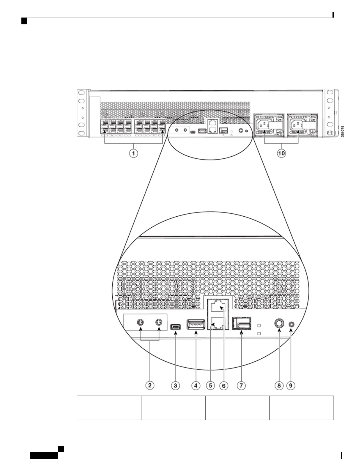
Figure 1: Catalyst 6816-X-LE
Product Overview
1
MB or 1G SFP fiber-optic
ports
Catalyst 6840-X Switch Series Hardware Installation Guide
2
616 10G SFP+ ports or 100
Console port (RJ-45
Serial)
Page 15

Product Overview
Front Panel Components
7Grounding pad2
Ethernet management SFP
port
3
8USB mini Type B console
port
System ID (blue beacon
LED)
Reset button9USB Type A host port4
5
10Ethernet management
RJ-45 port
1
Power supplies that are ordered are installed in the switch. If the second power supply is not ordered,
Two power supply slots
1
a blank panel is installed.
Catalyst 6840-X Switch Series Hardware Installation Guide
3
Page 16
Front Panel Components
Product Overview
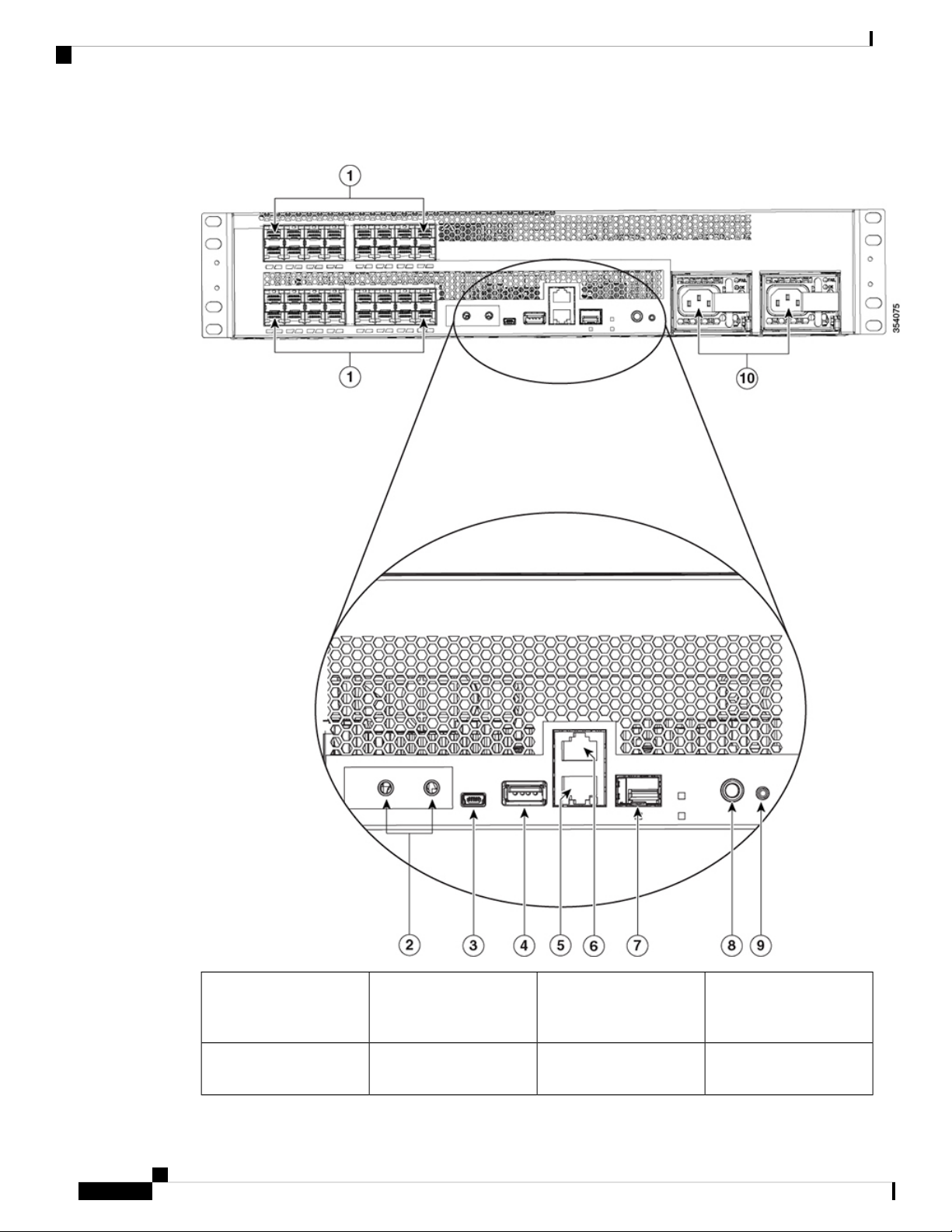
Figure 2: Catalyst 6832-X-LE
1
632 10G SFP+ ports or 100
MB or 1G SFP fiber-optic
Console port (RJ-45
Serial)
ports
7Grounding pad2
Ethernet management SFP
port
Catalyst 6840-X Switch Series Hardware Installation Guide
4
Page 17

Product Overview
Front Panel Components
3
8USB mini Type B console
port
System ID (blue beacon
LED)
Reset button9USB Type A host port4
5
10Ethernet management
RJ-45 port
2
Power supplies that are ordered are installed in the switch. If the second power supply is not ordered,
Two power supply slots
2
a blank panel is installed.
Catalyst 6840-X Switch Series Hardware Installation Guide
5
Page 18

Front Panel Components
Product Overview
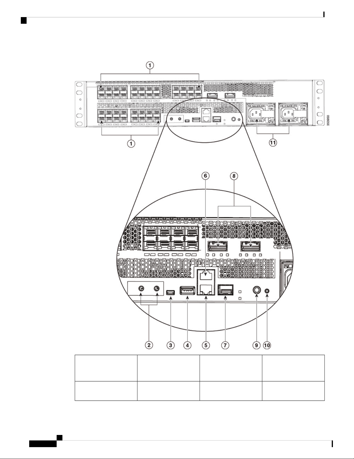
Figure 3: Catalyst 6824-X-LE-40G
1
724 10G SFP+ ports or 100
MB or 1G SFP fiber-optic
Ethernet management SFP
port
ports
8Grounding pad2
Two 40G QSFP+ uplink
ports
Catalyst 6840-X Switch Series Hardware Installation Guide
6
Page 19

Product Overview
Front Panel Components
3
9USB mini Type B console
port
System ID (blue beacon
LED)
Reset button10USB Type A host port4
5
11Ethernet management
RJ-45 port
6
Console port (RJ-45
Two power supply slots
3
Serial)
3
Power supplies that are ordered are installed in the switch. If the second power supply is not ordered,
a blank panel is installed.
Catalyst 6840-X Switch Series Hardware Installation Guide
7
Page 20
Front Panel Components
Product Overview
Figure 4: Catalyst 6840-X-LE-40G
1
740 10G SFP+ ports or 100
MB or 1G SFP fiber-optic
Two 40G QSFP+ uplink
ports
ports
8Grounding pad2
Ethernet management SFP
port
Catalyst 6840-X Switch Series Hardware Installation Guide
8
Page 21
Product Overview
SFP and SFP+ Transceiver Module Ports
3
port
5
RJ-45 port
6
Console port (RJ-45
Serial)
4
Power supplies that are ordered are installed in the switch. If the second power supply is not ordered,
a blank panel is installed.
SFP and SFP+ Transceiver Module Ports
The chassis contains 16/24/32/40 ports of 10-Gigabit Ethernet SFP+ or 100BASE-FX fiber-optic transceiver
modules. All ports support 1-Gigabit SFP, 10-Gigabit SFP+, or 100BASE-FX fiber-optic SFP modules with
two 40-Gigabit uplink ports on selected switch models.
The ports also support Cisco Trust Security (CTS) and virtual switch link (VSL) and can operate as an Instant
Access (IA) Parent in both 1-Gigabit, 10-Gigabit modes and 40-Gigabit modes.
The SFP and SFP+ transceiver modules provide copper or fiber-optic connections to other devices. These
transceiver modules are field-replaceable and provide the uplink interfaces when installed in an SFP module
slot. The SFP transceiver modules have LC connectors for fiber-optic connections or RJ-45 connectors for
copper connections.
9USB mini Type B console
System ID (blue beacon
LED)
Reset button10USB Type A host port4
11Ethernet management
Two power supply slots
4
For a list of supported SFP and SFP+ modules, see the switch data sheet: http://www.cisco.com/c/en/us/
products/collateral/switches/catalyst-6800-series-switches/datasheet-c78-734470.html.
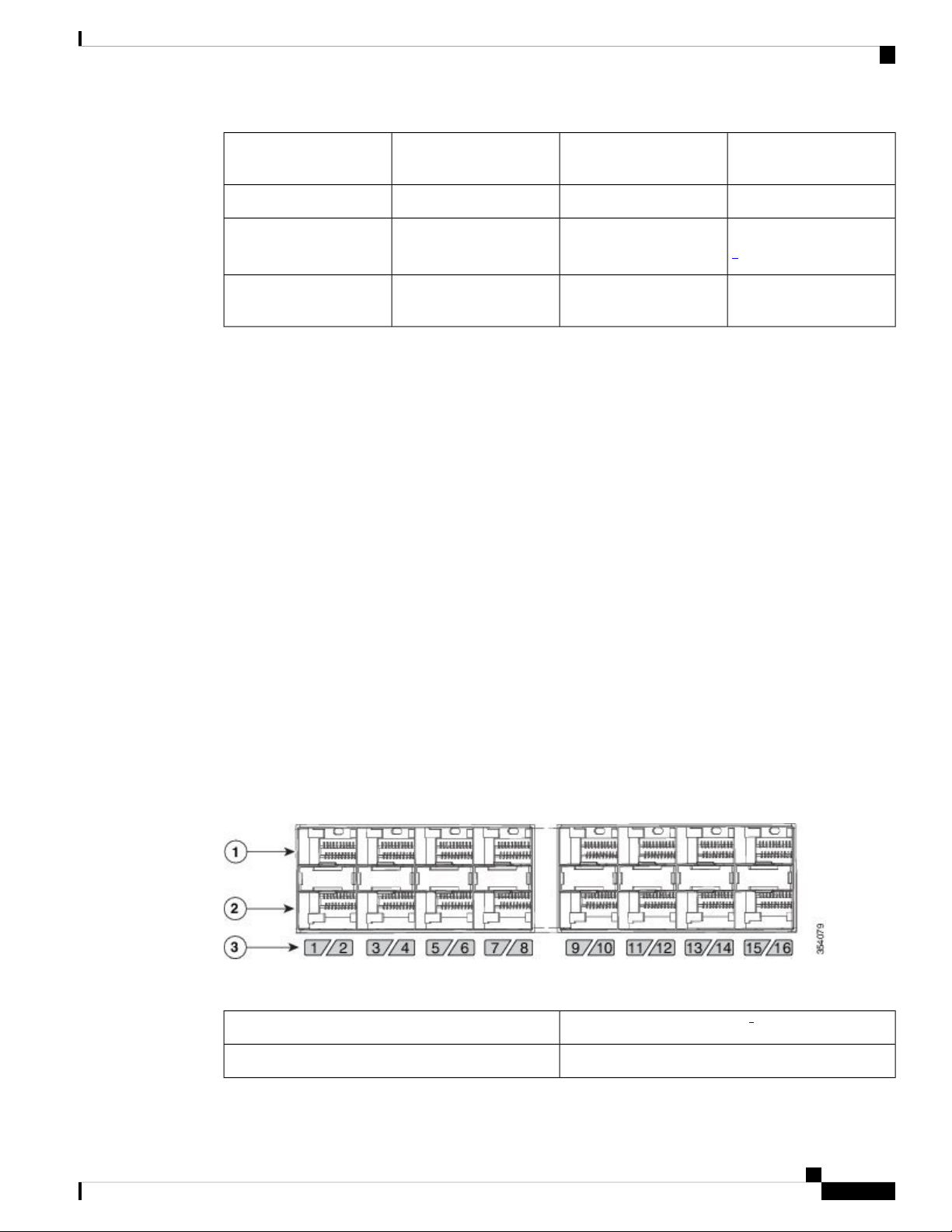
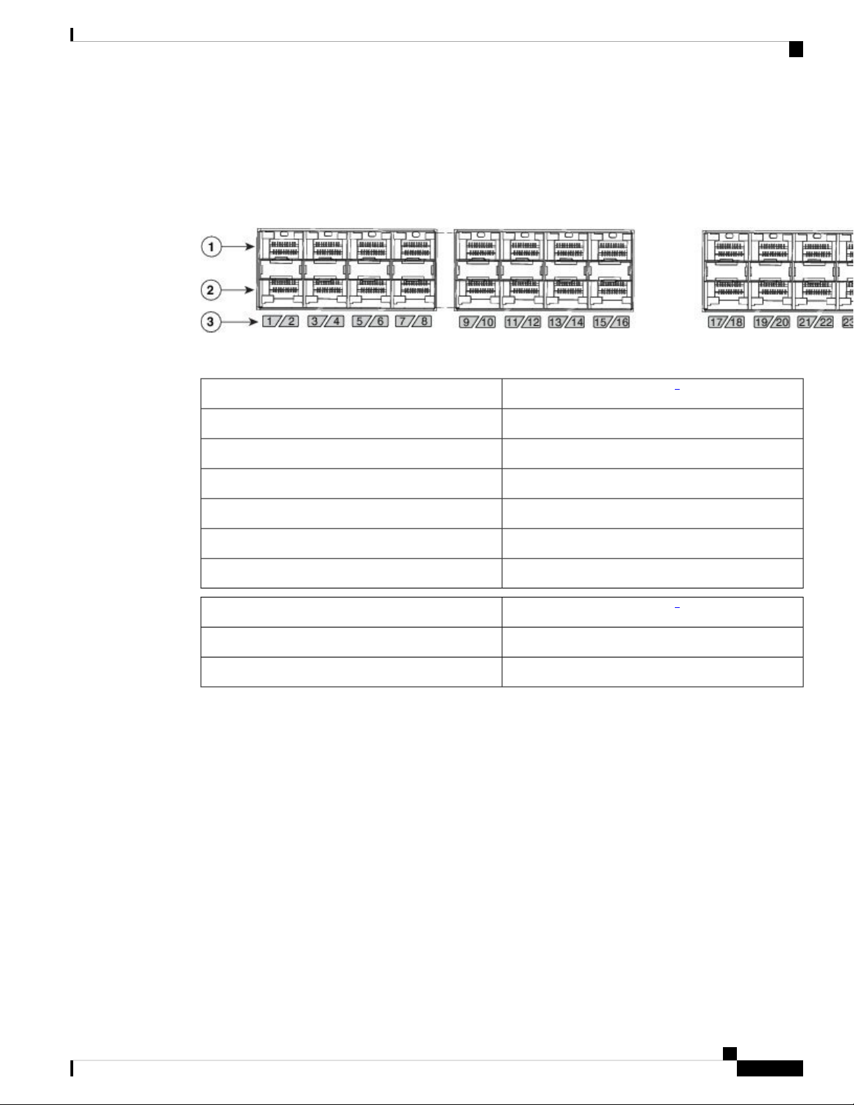
The odd-numbered ports are on the upper row and the even-numbered ports on the lower row. The following
figures show how the ports and the LEDs are numbered on different switch models. This section also explains
the port mapping between 10-Gigabit and 40-Gigabit ports.
Catalyst 6816-X-LE
Figure 5: 10G native port numbering
Table 2: Port mapping for Catalyst 6816-X-LE
10-Gigabit ports
Configurable 40-Gigabit ports
5
171, 2, 3, and 4
Catalyst 6840-X Switch Series Hardware Installation Guide
9
Page 22

SFP and SFP+ Transceiver Module Ports
Product Overview
10-Gigabit ports
Configurable 40-Gigabit ports
5
185, 6, 7, and 8
199, 10, 11, and 12
2013, 14, 15, and 16
5
To configure 10G ports to function as 40G ports, you need to use adapter cables that connect four 10G
SFP+ ports of the switch on one end to a 40G QSFP port of the switch on the other end.
Catalyst 6832-X-LE
Figure 6: 10G native port numbering
Table 3: Port mapping for Catalyst 6832-X-LE
10-Gigabit ports
Configurable 40-Gigabit ports
6
331, 2, 3, and 4
345, 6, 7, and 8
359, 10, 11, and 12
3613, 14, 15, and 16
3717, 18, 19, and 20
3821, 22, 23, and 24
3925, 26, 27, and 28
4029, 30, 31, and 32
Catalyst 6840-X Switch Series Hardware Installation Guide
10
Page 23
Product Overview
SFP and SFP+ Transceiver Module Ports
6
To configure 10G ports to function as 40G ports, you need to use adapter cables that connect four 10G
SFP+ ports of the switch on one end to a 40G QSFP port of the switch on the other end.
Catalyst 6824-X-LE-40G
Figure 7: 10G native port numbering
Table 4: Port mapping for Catalyst 6824-X-LE
10-Gigabit ports
Configurable 40-Gigabit ports
7
351, 2, 3, and 4
365, 6, 7, and 8
379, 10, 11, and 12
3813, 14, 15, and 16
3917, 18, 19, and 20
4021, 22, 23, and 24
40-Gigabit native ports
Configurable 10-Gigabit ports
8
27, 28, 29, and 3025
31, 32, 33, and 3426
7
To configure 10G ports to function as 40G ports, you need to use adapter cables that connect four 10G
SFP+ ports of the switch on one end to a 40G QSFP port of the switch on the other end.
8
To configure 40G ports to function as 10G ports, you need to use Cisco QSFP to four SFP+ Active
Optical Breakout Cables that connect a 40G QSFP port of the switch on one end to four 10G SFP+ ports
of the switch on the other end.
Catalyst 6840-X Switch Series Hardware Installation Guide
11
Page 24

SFP and SFP+ Transceiver Module Ports
Catalyst 6840-X-LE-40G
Figure 8: 10G native port numbering
Table 5: Port mapping for Catalyst 6840-X-LE
Product Overview
10-Gigabit ports
40-Gigabit native ports
Configurable 40-Gigabit ports
511, 2, 3, and 4
525, 6, 7, and 8
539, 10, 11, and 12
5413, 14, 15, and 16
5517, 18, 19, and 20
5621, 22, 23, and 24
5725, 26, 27, and 28
5829, 30, 31, and 32
5933, 34, 35, and 36
6037, 38, 39, and 40
Configurable 10-Gigabit ports
43, 44, 45,, and 4641
9
10
47, 48, 49, and 5042
9
To configure 10G ports to function as 40G ports, you need to use adapter cables that connect four 10G
SFP+ ports of the switch on one end to a 40G QSFP port of the switch on the other end.
10
To configure 40G ports to function as 10G ports, you need to use Cisco QSFP to four SFP+ Active
Optical Breakout Cables that connect a 40G QSFP port of the switch on one end to four 10G SFP+ ports
of the switch on the other end.
Catalyst 6840-X Switch Series Hardware Installation Guide
12
Page 25

Product Overview
Power Supply Slots
The chassis has two power supply slots that accept either AC-input or DC-input power supplies, or one of
each. The chassis is delivered with power supplies pre-installed in the power supply slots. If only one power
supply is ordered, then a blank cover is installed in the empty power supply slot, which must remain installed
if a power supply is not installed.
Table 6: Power supplies supported by the switches
Power Supply Slots
Power SupplySwitch
750W and 1100WCatalyst 6816-X-LE
750W and 1100WCatalyst 6832-X-LE
750W and 1100WCatalyst 6824-X-LE-40G
Catalyst 6840-X-LE-40G
Related Topics
Front Panel Components
Management Port
The management port is a 10/100/1000 copper Ethernet port directly connected to the route processor. The
switch also has a fibre port that can be used as the Ethernet Management port. It supports TFTP image
downloading, network management, SNMP, Telnet, and SSH connections. Flexible NetFlow export is not
supported on the management port. The management port is isolated from other ports in the system in a
dedicated management VRF; it is not part of the EARL forwarding logic. The management port provides
direct access to the CPU, even when the system is heavily loaded.
The management port is a Layer 3 port in host mode, and only accepts traffic that terminates on the router.
This port does not route packets between itself and other ports. The port processes only the following packet
types and properly enqueues them:
• Address Resolution Protocol (ARP)
1100W
Note
If you insert a 750W power supply in to
the power supply slot of a Catalyst
6840-X-LE-40G switch, the switch fails
to boot.
• IPv4 unicast
• IPv6 unicast
• Cisco Discovery Protocol (CDP)
• Link Layer Discovery Protocol (LLDP)
Related Topics
Front Panel Components
Catalyst 6840-X Switch Series Hardware Installation Guide
13
Page 26

Mini USB Type B Console Port
Mini USB Type B Console Port
The Mini USB 2.0 Type B console port functions as a second console connection to the route processor. The
USB console port connection uses a Mini USB 2.0 cable. The USB console interface speed is same as the
RJ-45 console interface speed.
Windows computers require a driver for the USB port. Before using the USB port, you must download the
required driver to your computer from https://software.cisco.com/download/
release.html?mdfid=282979369&softwareid=282855122&release=3.1
By default, USB-prefer mode is enabled for the port; but it can be overridden using the command-line interface
(CLI). When this port is in the USB-prefer mode, the RJ-45 console port will be disabled, if both the ports
are connected. For more information on using the CLI to configure the USB console interface, see the Catalyst
6500 Software Configuration Guide.
Related Topics
Front Panel Components
USB Type A Port
Product Overview
The USB 2.0 Type A port (disk0) is the only external storage interface for this switch. The port is connected
to the route processor, which allows the Cisco IOS software to access the port. The port supports Cisco USB
flash drives with capacities from 128 MB to 8 GB (USB devices with port densities of 128 MB, 256 MB, 1
GB, 4 GB, and 8 GB are supported). Cisco IOS software provides standard file system access to the flash
device: read, write, erase, and copy. The software also provides the ability to format the flash device with a
FAT file system (FAT32 and FAT16).
Related Topics
Front Panel Components
Console Port
The console port is an RJ-45 port that provides universal asynchronous receiver/transmitter (UART) support
to access the route processor with a serial console running at 9600 baud rate with 8 bits for data, no parity bit,
and 1 stop bit.
Related Topics
Front Panel Components
System Reset Button
This recessed access button is used to reset the system. Pressing the button brings down the route processor.
Related Topics
Front Panel Components
Fan Tray
14
The fan tray is responsible for cooling the entire chassis and interfacing with environmental monitors to trigger
alarms when conditions exceed thresholds. The fan tray supports Online Insertion and Removal (OIR).
Catalyst 6840-X Switch Series Hardware Installation Guide
Page 27

Product Overview
LED Indicators
LED Indicators
The fan tray contains four high-efficiency fans with variable speed settings and thermal sensors. If one fan
fails, the speed of the others is increased and a minor alarm is triggered. If a major fan tray failure occurs, the
system is shut down. The individual fans are not field replaceable; the entire fan tray must be replaced in the
event of a major fan tray failure. See Removing the Fan Tray, on page 61 for additional information about
the fan.
Related Topics
Front Panel Components
Fan Tray LED, on page 17
You can use the switch LEDs to monitor switch activity and performance. You can also monitor the status of
the fan tray assembly, and the power supplies.
Catalyst 6840-X Switch Series Hardware Installation Guide
15
Page 28

LED Indicators
Product Overview
Figure 9: Status, Fan, and System ID LEDs
Catalyst 6840-X Switch Series Hardware Installation Guide
16
Page 29
Product Overview
Status LED
System ID LED
Status LED
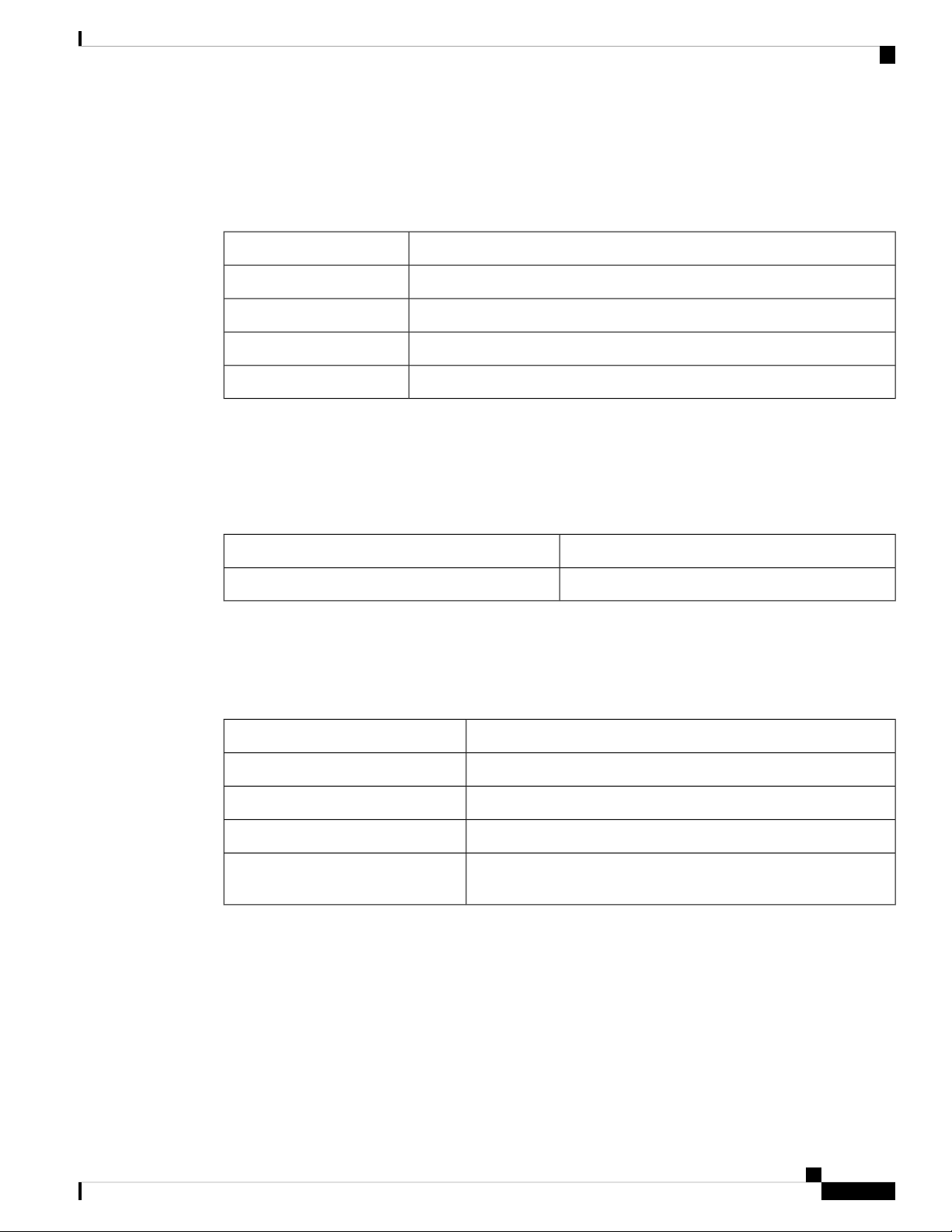
The status LED indicates the status of the system.
Table 7: Status LED Indicator
DescriptionColor/State
System is not operational.Off
System is operating normally without alarms.Green
System has triggered a minor environmental alarm.Amber
System has triggered a major environmental alarm.Red
The System ID (blue beacon) LED can be provisioned by the operator to indicate that the switch needs
attention.
Table 8: System ID LED Indicator
Management Port LED
This table describes the management port LEDs.
Table 9: Management Port LED Indicator
Alternating green and amber
Fan Tray LED
DescriptionColor/State
The system needs attention.Blinking blue
DescriptionColor/State
Port is not provisioned.Off
Port is provisioned, but administratively not operational.Amber
Port is linked up.Green
A port fault is detected, or the port beacon has been provisioned by
the operator.
The Fan LED is located on the front panel of the switch. The following image depicts the Fan LED, the system
status LED, and the blue beacon LED on the front panel of the switch.
Catalyst 6840-X Switch Series Hardware Installation Guide
17
Page 30

Power Supply LEDs
Table 10: Fan LED Indicator
Related Topics
Power Supply LEDs
The power supply includes LEDs on the front of the module. The different states of the LEDs are described
in the following table.
Figure 10: Power Supply LED
Product Overview
DescriptionColor/State
The fan tray is not receiving power; the fans have stopped.Off
All fans are operating normally.Green
The fan tray has a failure.Amber
Fan Tray, on page 14
Catalyst 6840-X Switch Series Hardware Installation Guide
18
Page 31

Product Overview
Rear Panel
Table 11: Power Supply LED Indicators
FAIL LED (Amber)OK LED (Green)AC Power Supply Condition
OffOffNo AC power to the power
supplies.
ONOffPower supply failure,
including over voltage, over
current, over temperature, and
fan failure conditions.
BlinkingOffPower supply needs attention,
activated for events like high
temperature, high power or
slow fan.
OffBlinkingInput AC is present, 3.3
voltage standby (VSB) is on
and the power supply unit is
switched off.
Rear Panel
OffOnPower supply is on and
operates normally.
Figure 11: Rear Panel
Fan trays1
Catalyst 6840-X Switch Series Hardware Installation Guide
19
Page 32

Rear Panel
Product Overview
Catalyst 6840-X Switch Series Hardware Installation Guide
20
Page 33

Preparing for Installation
• Safety Warnings, on page 21
• Site Requirements, on page 21
• Power Requirements, on page 30
• Cabling Requirements, on page 32
• Site Preparation Checklist, on page 32
Safety Warnings
Safety warnings appear throughout this publication in procedures that might harm you if performed incorrectly.
The warnings below are general warnings that are applicable to the entire publication.
CHAPTER 2
Warning
Warning
Warning
Only trained and qualified personnel should be allowed to install, replace, or service this equipment. Statement
1030
This unit is intended for installation in restricted access areas. A restricted access area can be accessed only
through the use of a special tool, lock and key, or other means of security. Statement 1017
Read the installation instructions before connecting the system to the power source. Statement 1004
Site Requirements
Planning a proper location for the switch and layout of the equipment rack or wiring closet is essential for
successful system operation. These sections describe some of the basic site requirements that you should be
aware of as you prepare to install your switch, including the following:
• Environmental factors can adversely affect the performance and longevity of your system.
• Install the switch in an enclosed, secure area, ensuring that only qualified personnel have access to the
switch and control of the environment.
Catalyst 6840-X Switch Series Hardware Installation Guide
21
Page 34

Temperature
Temperature
Preparing for Installation
• Equipment that is placed too closely together or that is inadequately ventilated may cause system
over-temperature conditions, leading to premature component failure.
• Poor equipment placement can make chassis panels inaccessible and difficult to maintain.
• The switch requires a dry, clean, well-ventilated, and air-conditioned environment.
• To ensure normal operation, maintain ambient airflow. If the airflow is blocked or restricted, or if the
intake air is too warm, an over-temperature condition may occur. The switch environmental monitor may
then shut down the system to protect the system components.
• Multiple switches can be rack mounted with little or no clearance above and below the chassis. However,
when mounting a switch in a rack with other equipment, or when placing it on the floor near other
equipment, ensure that the exhaust from other equipment does not blow into the air intake vent of the
switch chassis.
Temperature extremes may cause a system to operate at reduced efficiency and cause a variety of problems,
including premature aging and failure of chips, and failure of mechanical devices. Extreme temperature
fluctuations may also cause chips to become loose in their sockets. Observe the following guidelines:
Air Flow
• Ensure that the chassis has adequate ventilation.
• Do not place the chassis within a closed-in wall unit or on top of cloth, which can act as insulation.
• Do not place the chassis where it will receive direct sunlight, particularly in the afternoon.
• Do not place the chassis next to a heat source of any kind, including heating vents.
• Adequate ventilation is particularly important at high altitudes. Make sure that all the slots and openings
on the system remain unobstructed, especially the fan vent on the chassis.
• Clean the installation site at regular intervals to avoid buildup of dust and debris, which may cause a
system to overheat.
• If the system has been exposed to abnormally cold temperatures, allow a 2-hour warm-up period to bring
it to normal operating temperature before turning it on.
Failure to observe these guidelines may damage the chassis' internal components.
The switch is designed to be installed in an environment where there is a sufficient volume of air available to
cool the baseboard and other boards in the chassis, any installed modules, and power supplies. Any constraints
placed on the free flow of air through the chassis or an elevated ambient air temperature can cause the switch
to overheat and shut down.
To maintain proper air circulation through the switch chassis, maintain a minimum 6-inch (15 cm) separation
between a wall and the chassis air intake or a wall and the chassis hot air exhaust. In situations where the
switch chassis is installed in racks which are placed in parallel rows, you should allow a minimum of 12 inches
(30.5 cm) between the air intake of one chassis and the hot air exhaust of another chassis. Failure to maintain
adequate spacing between chassis can cause the switch chassis that is drawing in the hot exhaust air to overheat
and fail.
Catalyst 6840-X Switch Series Hardware Installation Guide
22
Page 35

Preparing for Installation
Cooling with the Fan Tray
If you are installing your switch in an enclosed or partially enclosed rack, we strongly recommend that you
verify that your site meets the following guidelines:
• Verify that there is a minimum of 6 inches (15 cm) of clearance between the sides of the rack and both
the chassis air intake grill and the chassis air exhaust grill.
• Verify that the ambient air temperature within the enclosed or partially enclosed rack is within the chassis
operating temperature limits. After installing the chassis in the rack, power up the chassis and allow the
chassis temperature to stabilize (approximately 2 hours). Measure the ambient air temperature at the
chassis air intake grill and at the chassis air exhaust grill by positioning an external temperature probe
approximately 1 inch (2.5 cm) away from the grills.
• If the ambient intake air temperature is less than 104°F (40°C), the rack meets the intake air temperature
criterion.
• If the ambient intake air temperature exceeds 104°F (40°C), the system might experience minor
temperature alarms and is in danger of overheating.
• If the ambient intake air temperature equals or is greater than 131°F (55°C), the system will
experience a major temperature alarm and shut down.
• Verify that the enclosed or partially enclosed rack allows an adequate flow of air through the switch
chassis as follows:
• If the difference between the measured intake air temperature and the exhaust air temperature does
not exceed 10°C, there is sufficient airflow in the rack.
• If the difference in air temperature exceeds 10°C, there is insufficient airflow to cool the chassis.
Note
• Plan ahead. Your switch that is installed in an enclosed or partially enclosed rack might currently meet
ambient air temperature and air flow requirements. However, if you add more chassis to the rack or you
add more modules to a chassis in the rack, the additional heat generated might cause the ambient air
temperature within the rack to exceed 104°F (40°C) and can cause minor alarms.
Cooling with the Fan Tray
The chassis fan tray provides cooling air for the switch chassis and components. If an individual fan within
the fan tray fails, the Fan Status LED turns amber. Individual fans within a fan tray cannot be replaced; you
must replace the entire fan tray.
The 10°C temperature differential between the intake and the exhaust must be
determined by taking measurements using external digital temperature probes.
Do not use the chassis internal temperature sensors to measure the temperature
differential.
Refer to your software configuration guide for information on environmental monitoring.
Catalyst 6840-X Switch Series Hardware Installation Guide
23
Page 36

Humidity
Humidity
Preparing for Installation
Figure 12: Catalyst 6840-X Switch Internal Air Flow
Related Topics
Installing the Fan Tray, on page 62
High-humidity conditions may cause moisture to enter the system, and cause corrosion of internal components
and degradation of properties such as electrical resistance, thermal conductivity, physical strength, and size.
Extreme moisture buildup inside the system may result in electrical short circuit, which may cause serious
damage to the system. Each system is rated to operate at 5 to 90 percent relative humidity, with a humidity
gradation of 10 percent per hour. In storage, a system can withstand 5 to 95 percent relative humidity. Buildings
in which climate is controlled by air-conditioning in the warmer months and by heat during the colder months
usually maintain an acceptable level of humidity for system equipment. However, if a system is located in an
unusually humid location, a dehumidifier should be used to maintain the humidity within an acceptable range.
Altitude
Operating a system at high altitude (low pressure) reduces the efficiency of forced and convection cooling
and may result in electrical problems related to arcing and corona effects. This condition may also cause sealed
components with internal pressure, such as electrolytic capacitors, to fail or perform at reduced efficiency.
Dust and Particles
Fans cool power supplies and system components by drawing in room-temperature air and exhausting heated
air out through various openings in the chassis. However, fans also ingest dust and other particles, causing
contaminant buildup in the system and increased internal chassis temperature. A clean operating environment
can greatly reduce the negative effects of dust and other particles, which act as insulators and interfere with
the mechanical components in the system. The standards listed below provide guidelines for acceptable
working environments and acceptable levels of suspended particulate matter:
• National Electrical Manufacturers Association (NEMA) Type 1
• International Electrotechnical Commission (IEC) IP-20
Corrosion
Corrosion of system connectors is a gradual process that may eventually lead to intermittent failures of electrical
circuits. The oil from a person’s fingers or prolonged exposure to high temperature or humidity may corrode
the gold-plated edge connectors and pin connectors on various components in the system. To prevent corrosion,
Catalyst 6840-X Switch Series Hardware Installation Guide
24
Page 37

Preparing for Installation
avoid touching contacts on boards and cards, and protect the system from extreme temperatures and moist,
salty environments.
EMI and Radio Frequency Interference
EMI and radio frequency interference (RFI) from a system can adversely affect devices such as radio and
television (TV) receivers operating near the system. Radio frequencies emanating from a system can also
interfere with cordless and low-power telephones. Conversely, RFI from high-power telephones can cause
spurious characters to appear on the system monitor. RFI is defined as any EMI with a frequency above 10
kilohertz (kHz). This type of interference can travel from the system to other devices through the power cable
and power source, or through the air in the form of transmitted radio waves. The Federal Communications
Commission (FCC) publishes specific regulations to limit the amount of EMI and RFI emitted by computing
equipment. Each system meets these FCC regulations. To reduce the possibility of EMI and RFI, follow these
guidelines:
• Always operate the system with the chassis covers installed.
• Ensure that all chassis slots are covered by a metal filler bracket and that an unused power supply bay
has a metal cover plate installed.
EMI and Radio Frequency Interference
Note
Caution
• Ensure that the screws on all peripheral cable connectors are securely fastened to their corresponding
connectors on the back of the chassis.
• Always use shielded cables with metal connector shells for attaching peripherals to the system.
When wires are run for any significant distance in an electromagnetic field, interference can occur between
the field and the signals on the wires. This fact has two implications for the construction of plant wiring:
• Bad wiring practice can result in radio interference emanating from the plant wiring.
• Strong EMI, especially when it is caused by lightning or radio transmitters, can destroy the signal drivers
and receivers in the chassis, and even create an electrical hazard by conducting power surges through
lines into equipment.
To predict and provide a remedy for strong EMI, consult experts in RFI.
If you use twisted-pair cable in your plant wiring with a good distribution of grounding conductors, the plant
wiring is unlikely to emit radio interference. If you exceed the recommended distances, use a high-quality
twisted-pair cable with one ground conductor for each data signal when applicable.
Category 5e, Category 6, and Category 6a cables can store large levels of static electricity because of the
dielectric properties of the materials used in their construction. Always ground the cables (especially in new
cable runs) to a suitable and safe earth ground before connecting them to the module.
If the wires exceed the recommended distances, or if wires pass between buildings, give special consideration
to the effect of a lightning strike in your vicinity. The electromagnetic pulse caused by lightning or other
high-energy phenomena can easily couple enough energy into unshielded conductors to destroy electronic
devices. If you have had problems of this sort in the past, you may want to consult experts in electrical surge
suppression and shielding.
Catalyst 6840-X Switch Series Hardware Installation Guide
25
Page 38

Power Source Interruptions
Power Source Interruptions
Systems are especially sensitive to variations in voltage supplied by the AC power source. Overvoltage,
undervoltage, and transients (or spikes) can erase data from memory or even cause components to fail. To
protect against these types of problems, power cables should always be properly grounded. Also, place the
system on a dedicated power circuit (rather than sharing a circuit with other heavy electrical equipment). In
general, do not allow the system to share a circuit with any of the following:
• Copy machines
• Air conditioners
• Vacuum cleaners
• Space heaters
• Power tools
• Teletype machines
• Laser printers
Preparing for Installation
• Facsimile machines
• Any other motorized equipment
Besides these appliances, the greatest threats to a system's power supply are surges or blackouts that are caused
by electrical storms. Whenever possible, turn off the system and peripherals, if any, and unplug them from
their power sources during thunderstorms. If a blackout occurs—even a temporary one—while the system is
turned on, turn off the system immediately and disconnect it from the electrical outlet. Leaving the system on
may cause problems when the power is restored; all other appliances left on in the area may create large
voltage spikes that may damage the system.
System Grounding
You must install a system ground as part of the chassis installation process. Chassis installations that rely only
on the AC third-prong ground are insufficient to adequately ground the systems.
Proper grounding practices ensure that the buildings and the installed equipment within them have
low-impedance connections and low-voltage differentials between chassis. When you install a system ground,
you reduce or prevent shock hazards, chances of equipment damage due to transients, and the potential for
data corruption.
Without proper and complete system grounding, you run the risk of increased component damage due to ESD.
Additionally, you have a greatly increased chance of data corruption, system lockup, and frequent system
reboot situations by not using a system ground.
26
Caution
Installations that rely solely on system grounding that uses only an AC third-prong ground run a substantially
greater risk of equipment problems and data corruption than those installations that use both the AC third-prong
ground and a properly installed system ground.
The following table lists some general grounding practice guidelines.
Catalyst 6840-X Switch Series Hardware Installation Guide
Page 39

Preparing for Installation
System Grounding
Table 12: Grounding Practice Guidelines
Environment
direct lightning strikes.
For example, some places in the United
States, such as Florida, are prone to
more lightning strikes than other areas.
area where lightning storms occur
frequently, but is not prone to direct
lightning strikes.
of information technology equipment
and industrial equipment, such as
welding.
subject to natural environmental noise
or man-made industrial noise. This
building contains a standard office
environment. This installation has a
history of malfunction due to
electromagnetic noise.
Severity Level
HighCommercial building is subjected to
HighCommercial building is located in an
Medium to HighCommercial building contains a mix
MediumExisting commercial building is not
Grounding RecommendationsElectromagnetic Noise
All lightning protection devices must be
installed in strict accordance with
manufacturer recommendations.
Conductors carrying lightning current
should be spaced away from power and
data lines in accordance with applicable
recommendations and codes. Best
grounding practices must be closely
followed.
Best grounding practices must be closely
followed.
Best grounding practices must be closely
followed.
Best grounding practices must be closely
followed. Determine source and cause of
noise if possible, and mitigate as closely as
possible at the noise source or reduce
coupling from the noise source to the
victim equipment.
to natural environmental noise or
man-made industrial noise. This
building contains a standard office
environment.
subject to natural environmental noise
or man-made industrial noise. This
building contains a standard office
environment.
LowNew commercial building is not subject
Best grounding practices should be
followed as closely as possible.
Electromagnetic noise problems are not
anticipated, but installing a best-practice
grounding system in a new building is often
the least expensive route, and the best way
to plan for the future.
LowExisting commercial building is not
Best grounding practices should be
followed as much as possible.
Electromagnetic noise problems are not
anticipated, but installing a best-practice
grounding system is always recommended.
Catalyst 6840-X Switch Series Hardware Installation Guide
27
Page 40

Maintaining Safety with Electricity
Note
In all situations, grounding practices must comply with Section 250 of the National Electric Code (NEC)
requirements or local laws and regulations. A 6 AWG grounding wire is preferred from the chassis to the rack
ground or directly to the common bonding network (CBN). The equipment rack should also be connected to
the CBN with a 6 AWG grounding wire.
Note
Always ensure that all of the modules are completely installed and that the captive installation screws are
fully tightened. In addition, ensure that all the I/O cables and power cords are properly seated. These practices
are normal installation practices and must be followed in all installations.
Preparing for Installation
Caution
Category 5e, Category 6, and Category 6a cables can store large levels of static electricity because of the
dielectric properties of the materials used in their construction. Always ground the cables (especially in new
cable runs) to a suitable and safe earth ground before connecting them to the module.
Maintaining Safety with Electricity
When working on electrical equipment, follow these guidelines:
• Do not work alone if potentially hazardous conditions exist anywhere in your work space.
• Never assume that power is disconnected from a circuit; always check the circuit before working on it.
• Look carefully for possible hazards in your work area, such as damp floors, ungrounded power extension
cables, frayed or damaged power cords, and missing safety grounds.
• If an electrical accident occurs, proceed as follows:
• Use extreme caution; do not become a victim yourself.
• Disconnect power from the system.
• If possible, send another person to get medical aid. Otherwise, assess the condition of the victim
and then call for help.
• Determine if the person needs rescue breathing or external cardiac compressions; then take appropriate
action.
• Use the product within its marked electrical ratings and product usage instructions.
• Install the product in compliance with local and national electrical codes.
• If any of the following conditions occur, contact the Cisco Technical Assistance Center:
• The power cable or plug is damaged.
• An object has fallen into the product.
• The product has been exposed to water or other liquids.
• The product has been dropped or shows signs of damage.
Catalyst 6840-X Switch Series Hardware Installation Guide
28
Page 41

Preparing for Installation
Preventing Electrostatic Discharge Damage
• The product does not operate correctly when you follow the operating instructions.
• Use the correct external power source. Operate the product only from the type of power source indicated
on the electrical ratings label. If you are not sure of the type of power source required, consult the Cisco
Technical Assistance Center or a local electrician.
• Use approved power cables only. You have been provided with one or more power cables with your
chassis power supply that are intended for use in your country, based on the shipping location. Should
you need to purchase additional power cables, ensure that they are rated for the product and for the
voltage and current marked on the product’s electrical ratings label. The voltage and current rating of
the power cable should be greater than the ratings marked on the label.
• To help prevent electrical shock, plug all the power cables into properly grounded electrical outlets.
These power cables are equipped with three-prong plugs to ensure proper grounding. Do not use adapter
plugs or remove the grounding prong from a power cable.
• Observe power strip ratings. Make sure that the total current rating of all products that are plugged into
the power strip does not exceed 80 percent of the power strip rating.
• Do not modify power cables or plugs yourself. Consult with a licensed electrician or your power company
for site modifications. Always follow your local and national wiring codes.
Preventing Electrostatic Discharge Damage
To prevent ESD damage, follow these guidelines:
• Always use an ESD wrist strap and ensure that it makes maximum contact with bare skin. ESD grounding
straps are available with banana plugs, metal spring clips, or alligator clips. All switch chassis are equipped
with a banana plug connector (identified by the ground symbol next to the USB port) somewhere on the
front panel. If you have an older chassis equipped with a plastic banana plug connector, it is recommend
that you use either the supplied ESD grounding wrist strap (with a metal clip) or an ESD grounding wrist
strap equipped with an alligator clip. If you have a newer chassis that has a bare metal hole as the banana
plug connector (also identified by the ground symbol next to the USB port), we recommend that you use
a personal ESD grounding strap equipped with a banana plug.
• If you choose to use the disposable ESD wrist strap supplied with most FRUs or an ESD wrist strap
equipped with an alligator clip, you must attach the system ground lug to the chassis in order to provide
a proper grounding point for the ESD wrist strap.
• If your chassis does not have the system ground attached, you must install the system ground. See
Establishing the System Ground, on page 45 for installation instructions and locations of the chassis
system ground pads.
Attaching the ESD Wrist Strap
After you install the system ground lug, follow these steps to correctly attach the ESD wrist strap:
Procedure
Step 1 Secure the ESD wrist strap equipped with an alligator clip to your bare skin.
Catalyst 6840-X Switch Series Hardware Installation Guide
29
Page 42

Preparing for Installation
Power Requirements
Step 2 Grasp the spring or alligator clip on the ESD wrist strap and momentarily touch the clip to a bare metal spot
(unpainted surface) on the rack. It is recommend that you touch the clip to an unpainted rack rail so that any
built-up static charge is then safely dissipated to the entire rack.
Step 3 Attach the alligator clip directly over the head of the system ground lug screw or to the system ground lug
barrel.
Figure 13: Attaching the ESD Wrist Strap to the System Ground Lug Screw
Power Requirements
When preparing your site for the switch installation, follow these requirements:
• When installing two power supplies, connect each power supply to a separate input power source. If you
fail to do this, your system might be susceptible to total power failure due to a fault in the external wiring
or a tripped circuit breaker.
• To prevent a loss of input power, be sure that the total maximum load on each source circuit is within
the current ratings of the wiring and breakers.
• You might decide to use an uninterruptible power supply (UPS) to protect against power failures at your
site. Be aware when selecting a UPS that some UPS models that use ferroresonant technology can become
unstable when operating with the switch power supplies which use power factor correction (PFC). This
Alligator clip3System ground lug1
4ESD wrist strap2
Clip attached to the
system ground lug
Catalyst 6840-X Switch Series Hardware Installation Guide
30
Page 43

Preparing for Installation
Power Connection Guidelines for AC-Powered Systems
can cause the output voltage waveform to the switch to become distorted resulting in an undervoltage
situation in the system.
• The AC-input power supply has a detachable power cord that allows you to connect each power supply
to the site power source.
• Plug the DC wiring connector into the inlet receptacle at the rear of the chassis. For a DC installation,
you should secure the plug to the power supply by tightening both captive screws on the plug.
• If you are using a 200/240 VAC power source in North America, the circuit must be protected by a
two-pole circuit breaker.
• The source AC outlet must be within 6 feet (1.8 meters) of the system and should be easily accessible.
• The AC power receptacles used to plug in the chassis must be the grounding type. The grounding
conductors that connect to the receptacles should connect to protective earth ground at the service
equipment.
Power Connection Guidelines for AC-Powered Systems
This section provides the basic guidelines for connecting the switch AC power supplies to the site power
source:
• Each chassis power supply should have a separate, dedicated branch circuit.
• For North America:
• The 1100 W power supply requires a 10 A circuit, if the voltage is 110V.
• For International:
• Circuits should be sized according to local and national codes.
• If you are using a 200/240 VAC power source in North America, the circuit must be protected by a
two-pole circuit breaker.
• The source AC outlet must be within 6 feet (1.8 meters) of the system and should be easily accessible.
• The AC power receptacles used to plug in the chassis must be the grounding type. The grounding
conductors that connect to the receptacles should connect to protective earth ground at the service
equipment.
Power Connection Guidelines for DC-Powered Systems
This section provides the basic guidelines for connecting the switch DC-input power supplies to the site power
source:
• All power connection wiring should conform to the rules and regulations in the National Electrical Code
(NEC), as well as any local codes.
• The DC return must remain isolated from the system frame and the chassis (DC-I).
• For DC power cables, we recommend that you use commensurately rated, high-strand-count copper wire
cable. Connection to the DC-input power supply requires one earth ground cable, one source DC (–),
and one source DC return (+). The length of the cables depends on your switch location. These cables
are not available from Cisco Systems. They are available from any commercial cable vendor.
Catalyst 6840-X Switch Series Hardware Installation Guide
31
Page 44

Cabling Requirements
Preparing for Installation
• The color coding of the source DC power cable leads depends on the color coding of the site DC power
source. Typically, green or green and yellow indicate that the cable is a ground cable. Because there is
no color code standard for source DC wiring, you must ensure that the power cables are connected to
the DC-input power supply terminal block in the proper (+) and (–) polarity. In some cases, the source
DC cable leads might have a positive (+) or a negative (–) label. This label is a relatively safe indication
of the polarity, but you must verify the polarity by measuring the voltage between the DC cable leads.
When making the measurement, the positive (+) lead and the negative (–) lead must always match the
(+) and (–) labels on the DC-input power supply.
• The circuit breaker is considered to be the disconnect device and should be easily accessible.
• The circuit must be protected by a dedicated two-pole circuit breaker. The circuit breaker should be sized
according to the power supply input rating and local or national code requirements.
• For proper DC-input redundant power configurations on systems with multiple-input DC-input power
supplies, all pairs of source DC cables for one DC-input power supply must come from the same battery
system (A feed); all pairs of source DC cables for the second DC-input power supply must come from
a different battery system (B feed).
• For DC-input power supplies with multiple inputs, each DC input must be protected by a dedicated circuit
breaker or a fuse. The circuit breaker or the fuse must be sized according to the power supply input rating
and local or national electrical codes.
Cabling Requirements
When running power and data cables together in overhead cable trays or subfloor cable trays, be aware of the
following caution:
Caution
Caution
We strongly recommend that power cabling runs and other potential noise sources be located as far away as
practical from LAN cabling that terminates on Cisco equipment. In situations where this type of long parallel
cable runs exist and cannot be separated by at least 3.3 feet (1 meter), we recommend that you shield these
potential noise sources. To avoid interference, the source should be shielded by housing it in a grounded
metallic conduit.
Also be aware of the following caution concerning the use of Category 5e and Category 6 Ethernet cables:
Category 5e, Category 6, and Category 6a cables can store large levels of static electricity because of the
dielectric properties of the materials used in their construction. Always ground the cables (especially in new
cable runs) to a suitable and safe earth ground before connecting them to the module.
Site Preparation Checklist
The following table lists the site-planning activities that you should perform prior to installing the switch.
Completing each activity helps ensure a successful switch installation.
Catalyst 6840-X Switch Series Hardware Installation Guide
32
Page 45

Preparing for Installation
Site Preparation Checklist
Table 13: Site-Planning Activities
Time and DateVerified ByActivityTask No.
1
Space evaluation:
• Space and layout
• Floor covering
• Impact and vibration
• Lighting
• Maintenance access
2
Environmental evaluation:
• Ambient temperature
• Humidity
• Altitude
• Atmospheric contamination
• Airflow
3
Power evaluation:
• Input power type
• Power receptacles (Depends
on power supply)
• Receptacle proximity to the
equipment
• Dedicated (separate) circuits
for redundant power supplies
• UPS for power failures
• DC systems: Proper gauge
wire and lugs
4
Grounding evaluation:
• Circuit breaker size
• CO ground (AC- and
DC-powered systems)
Catalyst 6840-X Switch Series Hardware Installation Guide
33
Page 46

Site Preparation Checklist
Preparing for Installation
Time and DateVerified ByActivityTask No.
5
Cable and interface equipment
evaluation:
• Cable type
• Connector type
• Cable distance limitations
• Interface equipment
(transceivers)
6
EMI evaluation:
• Distance limitations for
signaling
• Site wiring
• RFI levels
Note
For power receptacles (depends on power supply), verify that each power supply installed in the chassis has
a dedicated AC source or DC source circuit.
Note
For UPS for power failures, refer to the power supply’s kVA rating as a sizing criteria in determining the
output required by the UPS.
Catalyst 6840-X Switch Series Hardware Installation Guide
34
Page 47

Installing the Switch
This chapter describes how to install Catalyst 6840-X switches. Pointers within the overall chassis installation
procedures point to separate installation procedures that cover installing various components and assemblies.
• Installation Tasks, on page 35
• Safety Warnings, on page 36
• Rack-Mounting Guidelines, on page 37
• Unpacking the Switch, on page 38
• Chassis Installation Kits and Cable Guides, on page 38
• Installing the Switch Chassis, on page 39
Installation Tasks
The process of installing the switch can be broken down into a series of tasks, which are described in the
following table.
CHAPTER 3
DescriptionTask
Unpacking the switch
Connecting the chassis to system ground
Installing and cabling the power supply or supplies
Catalyst 6840-X Switch Series Hardware Installation Guide
Remove the switch from the packaging materials.
Note
Install the switch.Installing the switch
Construct and attach a system ground wire from the
building (earth) ground to the system ground point on
the chassis.
Power supplies that are ordered with the switch are
installed in the switch. If ordered separately, install
the power supplies. Connect the power supplies.
Save the packaging material for later use
if you need to move the chassis.
35
Page 48

Safety Warnings
Installing the Switch
DescriptionTask
Cabling the chassis and modules to the network
Powering up the chassis
Safety Warnings
Warning
Warning
Class 1 laser product. Statement 1008
This unit is intended for installation in restricted access areas. A restricted access area can be accessed only
through the use of a special tool, lock and key, or other means of security. Statement 1017
The various ports on the chassis must be connected
to the network. This process can involve only
attaching a network interface cable to the port or it
can include the installation of a transceiver of some
type in port and then attaching the network interface
cable to the transceiver.
After completing the network cabling and making
sure that system ground is connected, the power
supplies can be turned on. The system powers up and
runs through a set of built-in diagnostics.
Warning
Warning
Warning
Warning
This unit might have more than one power supply connection. All connections must be removed to de-energize
the unit. Statement 1028
Only trained and qualified personnel should be allowed to install, replace, or service this equipment. Statement
1030
To prevent personal injury or damage to the chassis, never attempt to lift or tilt the chassis using the handles
on modules (such as power supplies, fans, or cards); these types of handles are not designed to support the
weight of the unit. Statement 1032
Hazardous voltage or energy is present on the backplane when the system is operating. Use caution when
servicing. Statement 1034
Catalyst 6840-X Switch Series Hardware Installation Guide
36
Page 49

Installing the Switch
Rack-Mounting Guidelines
Warning
This product requires short-circuit (overcurrent) protection, to be provided as part of the building installation.
Install only in accordance with national and local wiring regulations. Statement 1045
Warning
When installing or replacing the unit, the ground connection must always be made first and disconnected last.
Statement 1046
Warning
Warning
Installation of the equipment must comply with local and national electrical codes.. Statement 1074
Invisible laser radiation may be emitted from disconnected fibers or connectors. Do not stare into beams or
view directly with optical instruments. Statement 1051
Before starting the installation procedures in this chapter, see the “Site Preparation Checklist” section on page
2-15 to verify that all site planning activities were completed.
Rack-Mounting Guidelines
Note
Note
Caution
The switch is designed to be installed in standard 19-inch racks.
Before rack-mounting the switch, ensure that the equipment rack complies with the following guidelines:
• The width of the rack, measured between the two front-mounting strips or rails, must be one of the
following measurements:
• 17.5 inches (44.45 cm)
• 17.75 inches (45.09 cm)
• The depth of the rack, measured between the front- and rear-mounting strips, must be at least 19.25
inches (48.9 cm).
• The rack must have sufficient vertical clearance to insert the chassis: 8.75 inches (22.23 cm) (5 RU)
Chassis height is sometimes measured in rack units (RU or just U) where 1 RU or 1 U equals 1.75 in (44.45
mm). A typical server rack is 42 RU or 42 U in height.
If the rack is on wheels, ensure that the brakes are engaged and that the rack is stabilized.
Catalyst 6840-X Switch Series Hardware Installation Guide
37
Page 50

Unpacking the Switch
Installing the Switch
Warning
Warning
Note
Stability hazard. The rack stabilizing mechanism must be in place, or the rack must be bolted to the floor
before you slide the unit out for servicing. Failure to stabilize the rack can cause the rack to tip over. Statement
1048
To prevent bodily injury when mounting or servicing this unit in a rack, you must take special precautions to
ensure that the system remains stable. The following guidelines are provided to ensure your safety:
• This unit should be mounted at the bottom of the rack if it is the only unit in the rack.
• When mounting this unit in a partially filled rack, load the rack from the bottom to the top with the
heaviest component at the bottom of the rack.
• If the rack is provided with stabilizing devices, install the stabilizers before mounting or servicing the
unit in the rack. Statement 1006
To maintain proper air circulation through the Catalyst switch chassis, you should maintain a recommended
separation of a minimum of 6 inches (15 cm) between a wall and the chassis air intake or a wall and the chassis
air exhaust. You should also allow a minimum separation of 12 inches (30.5 cm) between the hot air exhaust
on one chassis and the air intake on another chassis. Failure to maintain adequate air space can cause the
chassis to overheat and the system to fail.
Unpacking the Switch
Note
Do not discard the shipping container when you unpack the switch. Flatten the shipping cartons and store
them with the pallet. You will need these containers if you need to move or ship the switch in the future.
Check the contents of the accessory kit. Verify that you received all listed equipment, which should include
the following:
• Grounding lug and disposable ESD strap.
• Optional equipment that you ordered, such as console cables, transceivers, or special connectors.
• Blank covers are installed for the power supply slots on the chassis.
Chassis Installation Kits and Cable Guides
The chassis ships with an accessory kit, which includes chassis installation kits and cable guides:
• Standard 19-inch rack-mount L brackets (factory-installed on the chassis). Associated rack-mounting
hardware is included in the accessory kit.
• Two cable management guides are included in the accessory kit.
Catalyst 6840-X Switch Series Hardware Installation Guide
38
Page 51

Installing the Switch
Installing the Switch Chassis
Installation Accessory Kits
The switch chassis is designed to be installed in a standard 19-inch rack, either open or enclosed. The chassis
is shipped with the 19-inch rack-mount L brackets that are factory installed on the left-front and right-front
of the chassis. Screws are included with the accessory kit that are used to secure the chassis in the rack
enclosure.
Note
Depending on the manufacturer, the rack posts might be prethreaded to accept either 10-32 or 12-24 screws.
If the rack posts are not prethreaded, you must install 10-32 or 12-24 clip nuts or cage nuts to secure the
rack-mount screws. The clip nuts or the cage nuts are not included as part of the accessory kit and must be
obtained on your own.
Installing the Switch Chassis
The accessory kit also contains the following:
• Cable guides— Two cable guides can be installed on the front of the chassis using the same sets of screws
that secure the chassis rack-mount brackets to the rack posts.
L Brackets on the Chassis
The switch chassis is shipped with two L brackets installed toward the front of each side of the chassis, as
shown in the following figure.
Figure 14: Brackets on the Switch Chassis
Right L bracket2Left L bracket1
Catalyst 6840-X Switch Series Hardware Installation Guide
39
Page 52

Installing the L Brackets in a rack
Installing the L Brackets in a rack
Note
In many older equipment racks, the rack posts are prethreaded to accept either 10-32 or 12-24 screws. Newer
rack enclosure posts might not be prethreaded. These rack enclosure posts require that you install 10-32 or
12-24 clip nuts or cage nuts to secure the rack-mount screws. The clip nuts or the cage nuts are not included
as part of the accessory kit and must be obtained on your own.
Before you install the shelf brackets, determine the clearance between the insides of the left and right rails of
your rack system:
• If the distance between the insides of the rails is 17.5 inches (44.45 cm), then follow the steps in Installing
the L Brackets on a Rack with 17.5 in. (44.45 cm) Opening, on page 40.
• If the distance between the insides of the rails is 17.75 inches (45.09 cm), then follow the steps in Installing
the L Brackets on a Rack with 17.75 in. (45.09 cm) Opening, on page 41.
Installing the L Brackets on a Rack with 17.5 in. (44.45 cm) Opening
Installing the Switch
Procedure
Step 1 Attach the L bracket to the chassis as shown in the following figure.
Figure 15: Attaching the L Bracket to the chassis
Step 2 Position the chassis in the rack and align the mounting holes in the L bracket with the mounting holes in the
equipment rack.
Step 3 Secure the chassis using four screws through the holes in the L bracket and into the rack post holes.
Catalyst 6840-X Switch Series Hardware Installation Guide
40
Page 53

Installing the Switch
Installing the L Brackets on a Rack with 17.75 in. (45.09 cm) Opening
Figure 16: Installing the chassis on a Rack with a 17.5 in. (44.45 cm) Opening
Installing the L Brackets on a Rack with 17.75 in. (45.09 cm) Opening
Procedure
Step 1 Attach the L bracket to the chassis as shown in the following figure.
Figure 17: Attaching the L Bracket to the chassis
Step 2 Position the chassis in the rack and align the mounting holes in the L bracket with the mounting holes in the
equipment rack.
Step 3 Secure the chassis using four screws through the holes in the L bracket and into the rack post holes.
Catalyst 6840-X Switch Series Hardware Installation Guide
41
Page 54

Installing the Chassis in a Two-Post Rack
Figure 18: Installing the chassis on a Rack with a 17.75 in. (45.09 cm) Opening
Installing the Switch
Installing the Chassis in a Two-Post Rack
Note
The chassis are designed to be mounted in equipment racks that meet ANSI/EIA 310-D and ETS 300-119
standards.
Procedure
Step 1 Before rack-mounting the chassis, determine if you need to move the L brackets so that the chassis is installed
in one of the recommended positions:
• Positioned so the front of the chassis is approximately flush with the front of the rack:
• The chassis is shipped with the L brackets in the correct location; there is no need to move them.
• Positioned so approximately one fourth of the chassis protrudes in front of the rack:
• Remove the screws in the L brackets.
• Reposition the L brackets to align with the first set of holes behind the holes where the L brackets
were originally installed (see figure below).
• Secure the brackets with the screws.
Catalyst 6840-X Switch Series Hardware Installation Guide
42
Page 55

Installing the Switch
Installing the Chassis in a Two-Post Rack
• Positioned so approximately one half of the chassis protrudes in front of the rack:
• Remove the screws in the L brackets.
• Reposition the L brackets to align with the second set of holes behind the holes where the L brackets
were originally installed (see figure below).
• Secure the brackets with the screws.
Figure 19: Locations of Screw Holes for Alternate Chassis Installation Positions
1
3Left L bracket already
attached. When the
chassis is installed, the
front of the chassis is
approximately flush with
the front of the rack.
2
4Right L bracket already
attached. When the
chassis is installed, the
front of the chassis is
approximately flush with
the front of the rack.
Screw holes for
reattaching the L brackets.
When the chassis is
installed, approximately
one quarter of it protrudes
in front of the rack.
Screw holes for
reattaching the L brackets.
When the chassis is
installed, approximately
one half of it protrudes in
front of the rack.
Step 2 Rest the back end of the chassis on the rack-mount shelf and carefully slide the chassis into the rack until the
L brackets meet the front rails of the rack system.
Step 3 Locate the rack post holes that align with the chassis L bracket holes. If the rack post holes are prethreaded,
determine if the threads are 10-32 or 12-24. If the rack post holes are unthreaded, install eight or ten (four or
five on each side) either 10-32 or 12-24 clip or cage nuts over the rack post holes to accept the installation
screws.
Note
Clip nuts or cage nuts are not included as part of the accessory kit that comes with the chassis. You
must obtain them yourself.
Step 4 If you want to install one or both of the optional cable guide assemblies, position the cable guides so that the
cable guide mounting holes are aligned with L bracket holes as shown in figure below.
Catalyst 6840-X Switch Series Hardware Installation Guide
43
Page 56

Installing the Switch
Installing the Chassis in a Two-Post Rack
Figure 20: Installing the Cable Mount Guides
Cable guide1
Step 5 Install all four M4.0x20mmL screws (two on each side) through the cable guide mounting holes, into the L
bracket holes. Tighten the screws securely.
Step 6 Secure the chassis using four screws through the holes in the L bracket and into the rack post holes.
Figure 21: Installing the Cable Mount Guides
10-32 or 12-24 screws1
What to do next
After installing the chassis in its location, complete the installation process by following these procedures:
Catalyst 6840-X Switch Series Hardware Installation Guide
44
Page 57

Installing the Switch
• Connecting the chassis to system ground. See Establishing the System Ground, on page 45.
• Installing and connecting the power supplies to source power. For information on how to install and
cable power supplies, see the Installing Power Supplies, on page 55.
• Connecting to the switch console port. See Connecting the Switch Console Port, on page 47.
• Connecting to the uplink ports. Installing SFP and SFP+ Transceiver Modules, on page 48
• Powering-up the chassis and verifying the installation. See Verifying Switch Chassis Installation, on
page 50.
Establishing the System Ground
This section describes how to connect a system ground to the switch.
Establishing the System Ground
Caution
Note
Installations that rely solely on system grounding using only an AC third-prong ground run a substantially
greater risk of equipment problems and data corruption than those installations that use both the AC third-prong
ground and a properly installed system ground.
The system ground provides additional grounding for EMI shielding requirements and grounding for the low
voltage supplies (DC-DC converters) on the modules. You must observe the following system grounding
guidelines for your chassis:
• You must install the system ground connection with any other rack or system power ground connections
that you make. The system ground connection is required if FXS modules are installed or if this equipment
is installed in a U.S. or European Central Office.
• You must connect both the system ground connection and the power supply ground connection to an
earth ground. The system ground connection is required if FXS modules are installed or if this equipment
is installed in a U.S. or European Central Office.
• When using DC-input power supplies, you must install the system (ground before you attach the source
DC power cables to the DC PEM. Power down the chassis before attaching the system ground.
In all situations, grounding practices must comply with Section 250 of the National Electric Code (NEC)
requirements or local laws and regulations. A 8-24 AWG grounding wire is preferred from the chassis to the
rack ground or directly to the common bonding network (CBN). The equipment rack should also be connected
to the CBN with 8-24 AWG grounding wire.
Note
The system ground serves as the primary safety ground for chassis that are equipped with DC-input power
supplies. The DC-input power supplies for these chassis do not have a separate ground.
Required Tools and Equipment
To connect the system ground, you need the following tools and materials:
Catalyst 6840-X Switch Series Hardware Installation Guide
45
Page 58

Connecting the System Ground
• Grounding lug—A two-hole standard barrel lug. Supports up to 8-24 AWG wire. Supplied as part of
accessory kit.
• Grounding screws—Two M4 x 8 mm (metric) pan-head screws. Supplied as part of the accessory kit.
• Grounding wire—Not supplied as part of accessory kit. The grounding wire should be sized according
to local and national installation requirements. Depending on the power supply and system, a 12 AWG
to 6 AWG copper conductor is required for U.S. installations. 8-24 AWG wire is recommended. The
length of the grounding wire depends on the proximity of the switch to proper grounding facilities.
• No. 1 Phillips screwdriver.
• Crimping tool to crimp the grounding wire to the grounding lug.
• Wire-stripping tool to remove the insulation from the grounding wire.
Connecting the System Ground
To establish an earth ground for the chassis, you must attach a grounding cable from the chassis’ grounding
lug to the rack.
Installing the Switch
Before you begin
Review the following illustration and table.
Figure 22: System Ground Location
Location of system ground lug1
Procedure
Step 1 Use a wire-stripping tool to remove approximately 0.75 inch (19 mm) of the covering from the end of the
grounding wire.
Step 2 Insert the stripped end of the grounding wire into the open end of the grounding lug.
Catalyst 6840-X Switch Series Hardware Installation Guide
46
Page 59

Installing the Switch
Installing the Power Supplies in the Switch Chassis
Step 3 Crimp the grounding wire in the barrel of the grounding lug. Verify that the ground wire is securely attached
to the ground lug.
Step 4 Place the grounding wire lug against the grounding pad, making sure that there is solid metal-to-metal contact.
Step 5 Secure the grounding lug to the chassis with two M4 screws. Ensure that the grounding lug and the grounding
wire will not interfere with other switch hardware or rack equipment.
Step 6 Prepare the other end of the grounding wire with a ring lug, and secure it to the rack with a screw.
Installing the Power Supplies in the Switch Chassis
The chassis power supplies (AC or DC) might be shipped separately from the switch chassis. Remove the
power supply from its shipping packaging, and then install and connect it to the site power by referring to
Installing Power Supplies, on page 55.
Note
AC-input and DC-input power supplies can be mixed in a chassis.
Connecting the Switch Console Port
This section describes how to connect to the supervisor engine console port from a terminal or modem. The
console port on the supervisor engine allows you to perform the following functions:
• Configure the switch from the CLI.
• Monitor network statistics and errors.
• Configure SNMP agent parameters.
• Download software updates to the switch, or distribute software images residing in flash memory to
attached devices.
The console port is located on the front panel of the chassis.
The accessory kit that shipped with your switch might contain the necessary cable and adapters (depending
on if you ordered them) to connect a terminal or modem to the console port. To connect a terminal to the
console port using the cable and adapters provided, follow these steps:
Procedure
Step 1 Connect to the port using the RJ-45-to-RJ-45 cable and RJ-45-to-DB-25 DTE adapter or RJ-45-to-DB-9 DTE
adapter (labeled "Terminal").
Step 2 Position the cable in the cable guide (if installed). Make sure there are no sharp bends in the cable.
Step 3 Check the terminal documentation to determine the baud rate. The baud rate of the terminal must match the
default baud rate (9600 baud) of the console port. Set up the terminal as follows:
• 9600 baud
• 8 data bits
• No parity
Catalyst 6840-X Switch Series Hardware Installation Guide
47
Page 60

Connecting the Uplink Ports
• 1 stop bits
Connecting the Uplink Ports
SFP and SFP+ Transceiver Modules
The SFP and SFP+ transceiver modules provide copper or fiber-optic connections to other devices. These
transceiver modules are field-replaceable and provide the uplink interfaces when installed in an SFP module
slot. The SFP modules have LC connectors for fiber-optic connections or RJ-45 connectors for copper
connections.
For Cisco SFP and SFP+ transceiver modules documentation, including compatibility matrixes, refer to this
URL: http://www.cisco.com/en/US/products/hw/modules/ps5455/products_device_support_tables_list.html
Installing SFP and SFP+ Transceiver Modules
Installing the Switch
Before you begin
For cable specifications, see Appendix B, “Connector and Cable Specifications.”
Observe these precautions:
Warning
Step 1 Attach an ESD-preventive wrist strap to your wrist and to an earth ground surface.
Step 2 Find the send (Tx) and receive (Rx) markings that identify the top of the SFP module.
Class 1 laser product. Statement 1008
• Do not remove the dust plugs from the SFP transceiver modules or the rubber caps from the fiber-optic
cable until you are ready to connect the cable. The plugs and caps protect the module ports and cables
from contamination and ambient light.
• Removing and installing an SFP transceiver module can shorten its useful life. Do not remove and insert
any SFP transceiver module more often than is necessary.
• To prevent ESD damage, follow your normal board and component handling procedures when connecting
cables to the switch and other devices.
Procedure
On some SFP transceiver modules, the send and receive (Tx and Rx) markings might be shown by arrows
that show the direction of the connection.
Step 3 If the SFP transceiver module has a bale-clasp latch, move it to the open, unlocked position.
Step 4 Align the module in front of the slot opening, and push until you feel the connector snap into place.
Catalyst 6840-X Switch Series Hardware Installation Guide
48
Page 61

Installing the Switch
Installing SFP and SFP+ Transceiver Modules
Figure 23: Installing an SFP Module in the SFP Transceiver Module Port
Step 5 If the module has a bale-clasp latch, close it to lock the SFP transceiver module in place.
Note
If you are inserting the SFP transceiver module in the lower ports, you need to invert the module.
Step 6 Remove the SFP dust plugs and save.
Step 7 Connect the SFP cables.
Figure 24: Port with SFP Transceiver Modules Installed
Catalyst 6840-X Switch Series Hardware Installation Guide
49
Page 62

Removing SFP or SFP+ Transceiver Modules
Removing SFP or SFP+ Transceiver Modules
Procedure
Step 1 Attach an ESD-preventive wrist strap to your wrist and to an earth ground surface.
Step 2 Disconnect the cable from the SFP transceiver module. For reattachment, note which cable connector plug is
send (Tx) and which is receive (Rx).
Step 3 Insert a dust plug into the optical ports of the SFP transceiver module to keep the optical interfaces clean.
Step 4 If the module has a bale-clasp latch, pull the bale out and down to eject the module. If you cannot use your
finger to open the latch, use a small, flat-blade screwdriver or other long, narrow instrument to open it.
Step 5 Grasp the SFP transceiver module, and carefully remove it from the slot.
Step 6 Place the SFP transceiver module in an antistatic bag or other protective environment.
Verifying Switch Chassis Installation
Installing the Switch
Procedure
Step 1 Ensure that the unused power supply unit has a metal cover plate installed.
Step 2 Turn on the system. During the power-up sequence, the system performs a series of bootup diagnostic tests.
Additional system diagnostic tests are available. These tests allow you to perform a complete sanity check on
the system prior to inserting the system into your network and to monitor the health of the system while the
system is running. Refer to the “Online Diagnostics” section on page 3-19 for further information.
Tip
Online Diagnostics
The switch running Cisco IOS has many levels of online diagnostic capabilities. The online diagnostics are
divided into four categories:
• Bootup—Bootup diagnostics automatically run during bootup, module OIR, or switchover to a backup
supervisor engine.
• Background health—Monitoring diagnostic tests are continuously run by the system to monitor system
health.
When prestaging systems in a nonproduction environment, we recommend that you run all diagnostic
tests, including the disruptive tests, to prescreen the systems for any failures.
• On-demand online diagnostics—On-demand online diagnostics can be used to run any test from the CLI.
You can also run on-demand online diagnostics to perform a sanity check on the system hardware. Some
of these tests are disruptive and will impact traffic flow.You must follow the on-demand diagnostic
guidelines exactly to avoid false failures.
Catalyst 6840-X Switch Series Hardware Installation Guide
50
Page 63

Installing the Switch
Online Diagnostics
• Scheduled diagnostics—Scheduled diagnostics can be used to run any of the above tests at user-designated
intervals.
For complete information on the online diagnostic tests and how to run them, refer to the software configuration
guide.
Catalyst 6840-X Switch Series Hardware Installation Guide
51
Page 64

Online Diagnostics
Installing the Switch
Catalyst 6840-X Switch Series Hardware Installation Guide
52
Page 65

Installing and Removing Power Supplies
• Power Supply Overview, on page 53
• Installing Power Supplies, on page 55
• Removing Power Supplies, on page 59
• Finding the Serial Number, on page 59
Power Supply Overview
You can install two types of power supplies in the chassis:
Figure 25: Cisco Catalyst 6840-X AC Input Power Supply
CHAPTER 4
Catalyst 6840-X Switch Series Hardware Installation Guide
53
Page 66

Power Supply Overview
Installing and Removing Power Supplies
Figure 26: Cisco Catalyst 6840-X DC Input Power Supply
The switch chassis has two slots in which you can install power supplies using any of the following
combinations:
• Two AC-input power supplies
• Two DC-input power supplies
• One AC-input power supply and one DC-input power supply
• One AC-input power supply (leaving the blank cover on the other slot)
• One DC-input power supply (leaving the blank cover on the other slot)
Note
If you leave any power supply slots empty, you must ensure that the blank cover is installed in that slot to
maintain the designed airflow.
This table lists the power supply models.
DescriptionPart Number
Cisco Catalyst 6840-X power supply AC-750WC6840-X-750W-AC=
Cisco Catalyst 6840-X power supply DC-750WC6840-X-750W-DC=
Cisco Catalyst 6840-X power supply AC-1100WC6840-X-1100W-AC=
Cisco Catalyst 6840-X power supply DC-1100WC6840-X-1100W-DC=
The power supplies can work together in Redundant Mode, in which each power supply operates at
approximately 50 percent of its capacity, no greater than 60 percent and no less than 40 percent. If one power
supply fails, the other power supply can provide power for the entire system on its own. This is the default
and recommended mode for production.
Catalyst 6840-X Switch Series Hardware Installation Guide
54
Page 67

Installing and Removing Power Supplies
Installing Power Supplies
You follow the same steps to install the AC-input and DC-input power supplies, but you must ground them
differently.
Before You Begin
• The switch chassis must be installed in a cabinet or rack that is secured to the data center.
• Remove the power supply from its shipping container and remove any packaging.
• You need the following additional tools and equipment:
• Nut driver attachment for number 1 Phillips-head screwdriver or ratchet wrench with torque capability
(used only for DC-input power supplies).
• For the DC-input power supply, you need four power cables sized to reach the DC power source or
power interface unit (PIU).
Installing Power Supplies
• Grounding wire — Size this wire to meet local and national installation requirements. For U.S.
installations, you must use a 8-24 AWG copper conductor. For installations outside the U.S., consult
your local and national electrical codes. The length of the grounding wire depends on the proximity
of the switch to proper grounding facilities.
Inserting the Power Supply
To insert the power supply into the chassis, follow these steps:
Procedure
Step 1 Remove the blank cover and store it for future use.
Step 2 Verify that the power supply is not connected to any power sources.
Step 3 Hold the handle on the power supply with one handand position the power supply with its back end at the
open power supply bay. See the figure for an example (AC power supply is shown as an example, DC power
supply can be installed in the same way).
Step 4 Slide the unit all the way into the power supply bay until the release latch on the front of the power supply
clicks and prevents you from moving the power supply in or out of the chassis.
Catalyst 6840-X Switch Series Hardware Installation Guide
55
Page 68

Connecting to the Power Source
Figure 27: Installing the Power Supply
Installing and Removing Power Supplies
AC power supply1
Connecting to the Power Source
You follow the same steps to install the AC-input and DC-input power supplies, but you must ground them
differently.
• AC-input power supply—It is automatically grounded when you connect its power cable to the power
supply and the power source.
• DC-input power supply—You do not connect the power supply directly to the earth ground.
You use one power cord for each power supply to connect the power supply to its power source.
Before You Begin
Before you connect power supplies to power sources, ensure the following:
• The chassis is connected to an earth ground. See Establishing the System Ground, on page 45.
• You have receptacles for the power sources within reach of the power supply cables.
• If you are connecting to a DC power, check that you are using 8-24 AWG power cables to connect to
the power supply. The 8-24 AWG wire size applies to the negative [-], and positive [+] cables that connect
to negative and positive apertures on the connector. You have to procure the power cable.
• If you are installing more than one DC-input power supply, each must be protected by a dedicated circuit
breaker or a fuse that is sized according to the power supply input rating and the local or national electrical
code requirements.
• The power sources are rated as follows:
• For North American AC-input installations—10 A with 110 V circuits.
• For North American DC-input installations—(–48 VDC nominal at 37 A in North America (operating
range: –40.5 to –56 VDC).
Catalyst 6840-X Switch Series Hardware Installation Guide
56
Page 69

Installing and Removing Power Supplies
• For international installations—Size the circuits by local and national standards.
• The power supply is already inserted into the chassis.
Connecting to an AC Power Source
Caution
Ensure that the power source is OFF. As an added precaution, place the appropriate safety flag and lockout
devices at the source power circuit breaker, or place a piece of adhesive tape over the circuit breaker handle
to prevent accidental power restoration while you are working on the circuit.
Warning
Before performing any of the following procedures, ensure that power is removed from the DC circuit.
Statement 1003
Connecting to an AC Power Source
To connect to a power source, follow these steps:
Warning
Step 1 Plug the power cable into the power supply.
Step 2 Plug the other end of the power cable into an power source supplied by the data center.
Take care when connecting units to the supply circuit so that wiring is not overloaded. Statement 1018
Procedure
Note
When using redundant mode, connect each power supply to a separate power source.
Step 3 Verify that the power supply is receiving power and outputting DC power by checking that the OK LED is
on and is not yellow or blinking green. For an explanation of all the power supply LEDs and the conditions
that they indicate, see Power Supply LEDs.
When you first activate the power supply, you can verify the functionality of the LEDs by checking that each
LED turns on for a couple of seconds. If the OK LED is flashing green, check the AC power connections on
the power supply and the AC power source.
Connecting to a DC Power Source
Before you connect DC power supplies to power sources, you need to attach the DC connection wires to the
DC power connector. To wire the connector:
Warning
Before performing any of the following procedures, ensure that power is removed from the DC
circuit.Statement 1003
Catalyst 6840-X Switch Series Hardware Installation Guide
57
Page 70

Connecting to a DC Power Source
Installing and Removing Power Supplies
Warning
Hazardous voltage or energy may be present on DC power terminals. Always replace cover when terminals
are not in service. Be sure uninsulated conductors are not accessible when cover is in place. Statement 1075.
Procedure
Step 1 Turn off the power at the circuit breakers for the portions of the DC grid power that you are connecting to
and verify that all of the LEDs on the power supplies are off.
Step 2 Using a 1/8" flat head screwdriver or No. 1 Phillips head screwdriver, loosen the set screws on the connector
to freely accept the power wires. The connector will accept 8-24 AWG wires, use what your local electrical
code calls for.
Step 3 Strip 1/2" of insulation off the DC wires that you are using.
Step 4 Insert the black (DC negative) wire into the right aperture on the connector and tighten down the connection
set screw. Finger tight or about 3 ft./lbs should be sufficient.
Step 5 Insert the red (DC positive) wire into the left aperture on the connector and tighten down the connection set
screw. Do not tighten over 0.7 Nm.
Figure 28: Connecting to a DC Power Source
Step 6 For the powered down circuits connected to the power supplies, turn on the power at the circuit breaker. The
LEDs should flash and then the INPUT OK LED on the power supply should turn on.
Catalyst 6840-X Switch Series Hardware Installation Guide
58
Page 71

Installing and Removing Power Supplies
Removing Power Supplies
Procedure
Step 1 Turn off the power to the power supply that you are removing, as follows:
a) If you are removing a DC-input power supply, ensure that the power is turned off at the power source by
turning off the power for that circuit.
Step 2 Detach the power and ground cables, as follows:
• For the AC-input power supply, unplug the power cables that are attached to the power supply and the
power source.
• For the DC-input power supply, remove the power cables from the power source.
Step 3 Remove the power supply from the chassis, as follows:
a) Press the ejector latch on the right of the power supply.
b) Pull the power supply partially out of the slot by its handle.
c) Pull the power supply fully from the slot.
Removing Power Supplies
Caution
If you intend to operate the switch without installing another power supply in the empty slot, then
you must reinstall the blank cover over the empty power supply slot to ensure proper air flow in the
system and for safety reasons.
Finding the Serial Number
If you contact Cisco Technical Assistance, you need to know the serial number. These figures show where
the serial number is located. You can also use the show version privileged EXEC command to see the serial
number.
Catalyst 6840-X Switch Series Hardware Installation Guide
59
Page 72

Finding the Serial Number
Figure 29: Serial Number on the AC Power Supply
Installing and Removing Power Supplies
Catalyst 6840-X Switch Series Hardware Installation Guide
60
Page 73

Replacing the Fan Tray
• Required Tools, on page 61
• Removing the Fan Tray, on page 61
• Installing the Fan Tray, on page 62
• Checking the Installation, on page 63
• Finding the Fan Serial Number, on page 63
Required Tools
You might need a flat-blade or number 2 Phillips-head screwdriver to loosen or tighten the captive installation
screws on the fan tray.
Removing the Fan Tray
The fan tray is designed to be removed and replaced while the system is operating without presenting an
electrical hazard or damage to the system.
CHAPTER 5
Note
You have 120 seconds to remove and insert of the fan-tray, under specified ambient operating temperatures.
Warning
Step 1 Locate the fan tray as shown in the figure.
The fans might still be turning when you remove the fan from the chassis. Keep fingers, screwdrivers, and
other objects away from the openings in the fan’s housing. Statement 263
Procedure
Catalyst 6840-X Switch Series Hardware Installation Guide
61
Page 74

Installing the Fan Tray
Replacing the Fan Tray
Figure 30: Fan Tray Location
Location of fan tray1
Step 2 Loosen the fan tray captive installation screw by turning it counterclockwise.
Step 3 Grasp the fan tray, and pull it outward; gently move side to side, if necessary, to unseat the fan tray power
connector from the backplane.
Caution
Step 4 Pull the fan tray clear of the chassis, and set it aside.
When removing the fan tray, keep your hands and fingers away from the spinning fan blades. Let
the fan blades stop completely before you remove the fan tray.
Installing the Fan Tray
Procedure
Step 1 Position the fan tray with the captive installation screws in front of the fan tray cavity at the rear of the chassis.
Step 2 Place the fan tray into the chassis cavity so that the pin on the fan tray assembly is aligned with the hole on
the chassis. .
Step 3 Push the fan tray into the chassis until the power connector seats in the backplane and the captive installation
screw make contact with the chassis.
Step 4 Tighten the captive installation screws.
Related Topics
Cooling with the Fan Tray , on page 23
Catalyst 6840-X Switch Series Hardware Installation Guide
62
Page 75

Replacing the Fan Tray
Checking the Installation
Procedure
Step 1 Listen for the fans; you should immediately hear them operating. If you do not hear them, ensure that the fan
tray is inserted completely in the chassis and that the faceplate is flush with the switch back panel.
Step 2 Verify that the Fan LED is green. If the LED is amber, one or more of the fans are faulty.
If after several attempts the fans do not operate or if you experience trouble with the installation (for instance,
if the captive installation screws do not align with the chassis holes), contact a Cisco customer service
representative for assistance.
Checking the Installation
Finding the Fan Serial Number
If you contact Cisco Technical Assistance, you need to know the fan serial number. This figure shows where
the serial number is located. You can also use the show version privileged EXEC command to see the serial
number. For more information, refer to Fan Tray LED
Catalyst 6840-X Switch Series Hardware Installation Guide
63
Page 76

Finding the Fan Serial Number
Figure 31: Serial Number on the Fan
Replacing the Fan Tray
Catalyst 6840-X Switch Series Hardware Installation Guide
64
Page 77

Technical Specifications
• Switch Specifications, on page 65
• Power Supply Module Specifications, on page 67
• Power Supply AC Power Cords, on page 67
• Fan Tray Module Specifications, on page 68
• Chassis and Module Power and Heat Values , on page 69
Switch Specifications
SpecificationEnvironmental
APPENDIX A
C6840-X-LE-40GC6824-X-LE-40GC6832-X-LEC6816-X-LE
Temperature,
operating
Temperature,
nonoperating
and storage
Thermal
transition
(RH), ambient
(noncondensing
operating)
(RH), ambient
(noncondensing
nonoperating
and storage)
32°F to 104°F (0
to 40°C)
-4 to 149°F (-20
to 65°C)
0.5°C per minute
(hot to cold)
0.33°C per
minute (cold to
hot)
5% to 90%Humidity
5% to 95%Humidity
32°F to 104°F (0 to
40°C)
-4 to 149°F (-20 to
65°C)
0.5°C per minute (hot
to cold)
0.33°C per minute (cold
to hot)
32°F to 104°F (0 to
40°C)
-4 to 149°F (-20 to
65°C)
0.5°C per minute (hot
to cold)
0.33°C per minute (cold
to hot)
32°F to 104°F (0 to
40°C)
-4 to 149°F (-20 to
65°C)
0.5°C per minute (hot
to cold)
0.33°C per minute (cold
to hot)
Catalyst 6840-X Switch Series Hardware Installation Guide
65
Page 78

Technical Specifications
Technical Specifications
SpecificationEnvironmental
C6840-X-LE-40GC6824-X-LE-40GC6832-X-LEC6816-X-LE
Altitude,
operating
Shock and
vibration
Certified for operation: 0 to 6500 ft (0 to 2000 m)
Designed and tested for operation: -200 to 10,000 ft (-60 to 3000 m)
Shock
• Operational - 5 G 30 ms, half-sine (IEC 68-2-27)
• Nonoperational - 20 G, 7.5 ms, trapezoidal
Vibration
• Operational - 3 Hz to 500 Hz
• Power Spectral Density (PSD) - 0.0005 G2/Hz at 10 Hz and 200 Hz. 5 dB/octave roll
off at each end. 0.5 hours per axis (1.12 Grams).
Sound power level, 67 dB@27°CAcoustic
noise
Physical characteristics
Dimensions
• Height = 3.47 inches (8.81 cm)
• Width = 17.35 inches (44.07 cm)
• Depth = 21.8 inches (55.38 cm)
Weight
Chassis with
2 power
supplies and a
built-in fan
Airflow
• Rack Units (RU) = 2 RU
24.04 lbs/10.09
kgs
C6840-X-FAN
Note
The airflow in the Catalyst 6840-X switch chassis is from front to back. See Site
Requirements, on page 21 for recommended separations between walls and the
chassis air intake and air exhaust and between the air exhaust of one chassis with
the air intake of another chassis. Failure to maintain adequate air space can cause
the chassis to overheat and the system to fail.
37.03 lbs/16.8 kgs34.83 lbs/15.8 kgs33.95 lbs/15.4 kgs
Catalyst 6840-X Switch Series Hardware Installation Guide
66
Page 79

Technical Specifications
Power Supply Module Specifications
12.5"x2.15'x1.57'Physical
specifications
Power Supply Module Specifications
C6840-X-1100W-DC=C6840-X-1100W-AC=C6840-X-750W-DC=C6840-X-750W-AC=
range
range
(each input)
Rush-in current
input receptacles
Power cord rating
units (BTUs)
Output holdup
time
Environmental
conditions
90Vac to 264VacInput voltage
less than 10AInput current
50A hot turn-on
15A (US), 10A
(international)
16 milliseconds at
100% load
Operating
temperature: -5C
to 55oc at
1800m(6000ft)
max 25A @40V
or greater
90A35A cold turn-on
4msec at 100%
load
-5C to 55C at
1800m(6000ft)
max 13A @100Vac
max 7A @200Vac
50A hot turn-on
15A (US), 10A
(international)
load
Operating temperature:
-5C to 55oc at
1800m(6000ft)
-40Vdc to -72Vdc90Vac to 264Vac-40Vdc to -72Vdc
N/A50/60HzN/A50/60HzInput frequency
max 32A @40V or
greater
90A35A cold turn-on
PC 5/ 2-STF-7,62IEC 60320PC 5/ 2-STF-7,62IEC 60320Power supply
3753 BTU/hour3753 BTU/hour2559 BTU/hour2559 BTU/hourBritish thermal
4msec at 100% load16 milliseconds at 100%
-5C to 55C at
1800m(6000ft)
Power Supply AC Power Cords
The following table lists the specifications for the AC power cords that are available for the AC-input power
supply. The table also includes references to power cord illustrations.
Table 14: Power Supply AC Power Cords
Power Cords
AC Power Cord - 250V, 10A - Argentina(2.5 meter)CAB-250V-10A-AR
Power Cord, 250VAC 10A 3112 Plug, Australia(2.5 meter)CAB-9K10A-AU
Catalyst 6840-X Switch Series Hardware Installation Guide
67
Page 80

Fan Tray Module Specifications
Power Cords
Technical Specifications
AC Power Cord - 250V, 10A - Brazil (2.1 meter)CAB-250V-10A-BR
AC Power Cord - 250V, 10A - PRC(2.5 meter)CAB-250V-10A-CN
Power Cord, 250VAC 10A CEE 7/7 Plug, EU(2.5 meter)CAB-9K10A-EU
10A Power cable for India(2.5 meter)CAB-IND-10A
AC Power Cord - 250V, 10A - Israel(2.5 meter)CAB-250V-10A-IS
Power Cord, 250VAC 10A CEI 23-16/VII Plug, Italy(2.5 meter)CAB-9K10A-IT
AC Power Cord - 250V, 10A, South Africa (2.5 meter)CAB-250V-10A-ID
Power Cord, 250VAC 10A MP232 Plug, SWITZ(2.5 meter)CAB-9K10A-SW
CAB-9K10A-UK
CAB-9K12A-NA
CAB-AC-250V/13A
CAB-C13-CBN
CAB-C13-C14-2M
Fan Tray Module Specifications
Physical Specification
Dimensions (H x D x W)
Power Cord, 250VAC 10A BS1363 Plug (13 A fuse), UK(2.5
meter)
Power Cord, 125VAC 13A NEMA 5-15 Plug, North America(2.5
meter)
North America, NEMA L6-20 250V/20A plug-IEC320/C13
receptacle(2.0 meter)
Power Cord, 200/240V 6A North America(2.5 meter)CAB-N5K6A-NA
Cabinet Jumper Power Cord, 250 VAC 10A, C14-C13
Connectors(0.7 meter)
Power Cord Jumper, C13-C14 Connectors, 2 Meter Length(2
meter)
Power cord, C13 to C14 (recessed receptacle), 10A(3 meter)CAB-C13-C14-AC
3.0'' (H)X 12.7''(W) X1.774''(D)
1.08 KgWeight
Operating Specification
Airflow
Catalyst 6840-X Switch Series Hardware Installation Guide
68
120 CFM
Page 81

Technical Specifications
Chassis and Module Power and Heat Values
Chassis and Module Power and Heat Values
Module
Type
6816-X-LE
6832-X-LE
6824-X-LE-40G
6840-X-LE-40G
Module
Current (A)
Module
Power
(Watts)
AC-Input
Power
(Watts)
AC Heat
Diss
(BTU/HR)
DC Input
Power
(Watts)
DC Heat Diss
(BTU/HR)
450BTU/HR132 W450BTU/HR132 W108 W9 AFAN
2559BTU/HR750 W2559BTU/HR750 W420 W35 ACatalyst
2559BTU/HR750 W2559BTU/HR750 W620 W52 ACatalyst
2559BTU/HR750 W2559BTU/HR750 W620 W52 ACatalyst
3753BTU/HR1100 W3753BTU/HR1100 W900 W75 ACatalyst
Catalyst 6840-X Switch Series Hardware Installation Guide
69
Page 82

Chassis and Module Power and Heat Values
Technical Specifications
Catalyst 6840-X Switch Series Hardware Installation Guide
70
Page 83

Module Connectors and Cable Specifications
• Module Connectors, on page 71
• Cables and Adapters, on page 72
• Cleaning the Fiber-Optic Connectors, on page 74
Module Connectors
RJ-45 Connector
The RJ-45 connector is used to connect a Category 3, Category 5, Category 5e, or Category 6 foil twisted-pair
or unshielded twisted-pair cable from the external network to the module interface connector.
Figure 32: RJ-45 Interface Cable Connector
APPENDIX B
Caution
Caution
LC Connector
Category 5e, Category 6, and Category 6a cables can store large levels of static electricity because of the
dielectric properties of the materials used in their construction. Always ground the cables (especially in new
cable runs) to a suitable and safe earth ground before connecting them to the module.
To comply with GR-1089 intrabuilding and lightning immunity requirements, you must use a foil twisted-pair
(FTP) cable that is properly grounded at both ends.
The LC fiber optic connector is a small form-factor fiber-optic connector that provides high-density fiber
connectivity. The LC connector can be used with either MMF cable or SMF cable. The LC connector uses a
latching clip mechanism that is similar to the one used on the RJ-45 copper connector.
Catalyst 6840-X Switch Series Hardware Installation Guide
71
Page 84

Cables and Adapters
Module Connectors and Cable Specifications
Warning
Invisible laser radiation may be emitted from disconnected fibers or connectors. Do not stare into beams or
view directly with optical instruments. Statement 1051
Note
Make sure that the optical connectors are clean before making the connections. Contaminated connectors can
damage the fiber and cause data errors.
Figure 33: LC Fiber-Optic Connector
Cables and Adapters
SFP Module Cables
For cabling specifications, refer to the following notes:
• Cisco SFP and SFP+ Transceiver Module Installation Notes
Cable Pinouts
• Cisco 40-Gigabit QSFP+ Transceiver Modules Installation Note
Each port must match the wave-length specifications on the other end of the cable, and the cable must not
exceed the stipulated cable length. Copper 1000BASE-T SFP module transceivers use standard four twisted-pair,
Category 5 cable at lengths up to 328 feet (100 meters).
Figure 34: Four Twisted-Pair Straight-Through Cable Schematic
Catalyst 6840-X Switch Series Hardware Installation Guide
72
Page 85

Module Connectors and Cable Specifications
Figure 35: Four Twisted-Pair Semi-Cross Cable Schematic
Figure 36: Two Twisted-Pair Straight-Through Cable Schematic
Console Port Adapter Pinouts
Figure 37: Two Twisted-Pair Crossover Cable Schematic
Identifying a Crossover Cable
To identify a crossover cable, compare the two modular ends of the cable. Hold the cable ends side-by-side,
with the tab at the back. The wire connected to the pin on the outside of the left plug should be a different
color from the wire connected to the pin on the inside of the right plug.
Figure 38: Identifying a Crossover Cable
Console Port Adapter Pinouts
The RS-232 console port uses an 8-pin RJ-45 connector. Use an RJ-45-to-DB-9 adapter cable to connect the
switch console port to a console PC. You need to provide a RJ-45-to-DB-25 female DTE adapter to connect
the switch console port to a terminal.
Catalyst 6840-X Switch Series Hardware Installation Guide
73
Page 86

Cleaning the Fiber-Optic Connectors
Table 15: Console Port Signaling with a DB-9 Adapter
Module Connectors and Cable Specifications
Console DeviceRJ-45-to-DB-9 Terminal AdapterSwitch Console Port (DTE)
SignalDB-9 PinSignal
CTS8RTS
DSR6DTR
RxD2TxD
GND5GND
GND5GND
TxD3RxD
DTR4DSR
RTS7CTS
Table 16: Console Port Signaling with a DB-25 Adapter
Cleaning the Fiber-Optic Connectors
Console DeviceRJ-45-to-DB-25 Terminal AdapterSwitch Console Port (DTE)
SignalDB-25 PinSignal
CTS5RTS
DSR6DTR
RxD3TxD
GND7GND
GND7GND
TxD2RxD
DTR20DSR
RTS4CTS
Fiber-optic connectors are used to connect two fibers together. When these connectors are used in a
communications system, proper connection becomes a critical factor.
Fiber-optic cable connectors can be damaged by improper cleaning and connection procedures. Dirty or
damaged fiber-optic connectors can result in communication that is not repeatable or is inaccurate.
Fiber-optic connectors differ from electrical or microwave connectors. In a fiber-optic system, light is
transmitted through an extremely small fiber core. Because fiber cores are often 62.5 microns or less in
Catalyst 6840-X Switch Series Hardware Installation Guide
74
Page 87

Module Connectors and Cable Specifications
diameter, and dust particles range from a tenth of a micron to several microns in diameter, dust and any
contamination at the end of the fiber core can degrade the performance of the connector interface where the
two cores meet. The connector must be precisely aligned, and the connector interface must be absolutely free
of trapped foreign material.
Connector loss or insertion loss is a critical performance characteristic of a fiber-optic connector. Return loss
is also an important factor. Return loss specifies the amount of reflected light; the lower the reflection, the
better the connection. The best physical-contact connectors have return losses greater than -40 dB, although
-20 to -30 dB is more common.
The connection quality depends on two factors: the type of connector and the proper cleaning and connection
techniques. Dirty fiber connectors are a common source of light loss. Keep the connectors clean at all times,
and keep the dust covers installed when the connectors are not in use.
Before installing any type of cable or connector, use a lint-free alcohol pad from a cleaning kit to clean the
ferrule, the protective white tube around the fiber, and the end-face surface of the fiber.
As a general rule, whenever there is a significant, unexplained loss of light, clean the connectors.
Guidelines
Guidelines
Connectors that are used inside the system are cleaned by the manufacturer and connected to the adapters in
a proper manner. The operation of the system will be error free if the customer provides clean connectors on
the application side and follows these guidelines:
• Does not clean the inside of the connector adapters.
• Does not use force or quick movements when connecting the fiber-optic connectors in the adapters.
• Covers the connectors and adapters to keep the inside of the adapters or the surface of the connectors
from getting dirty when not using the connectors or while cleaning the chassis.
How to Clean the Fiber-Optic Connectors
Caution
Warning
Use extreme care when removing or installing connectors so that you do not damage the connector housing
or scratch the end-face surface of the fiber. Always install protective covers on unused or disconnected
components to prevent contamination. Always clean fiber connectors before installing them.
Invisible laser radiation may be emitted from disconnected fibers or connectors. Do not stare into beams or
view directly with optical instruments. Statement 1051
Procedure
Step 1 Use a lint-free tissue soaked in 99 percent pure isopropyl alcohol to gently wipe the faceplate. Wait five
seconds for the surfaces to dry, and repeat.
Step 2 Remove any residual dust from the faceplate with clean, dry, oil-free compressed air.
Catalyst 6840-X Switch Series Hardware Installation Guide
75
Page 88

Module Connectors and Cable Specifications
Module Connectors and Cable Specifications
Step 3 Use a magnifying glass or inspection microscope to inspect the ferrule at an angle. Do not look directly into
the aperture. Repeat the process if any contamination is detected.
Catalyst 6840-X Switch Series Hardware Installation Guide
76
Page 89

Repacking the Switch
If you need to return or move the switch chassis, follow these steps to repack the switch using the original
packaging material.
Procedure
Step 1 Set the chassis in the bottom pallet.
Figure 39: Packing Material
APPENDIX C
Step 2 Place the packing bag over the chassis.
Step 3 Place the front-packing material and power supply packing material around the chassis.
Step 4 Place the power supplies in the spaces provided in the power supply packing material.
Step 5 Place the top-packing material over the top of the chassis and power supplies.
Step 6 Place the rack-mount kit and the accessory kit on the top-packing material.
Note
Step 7 Place the outside carton over the entire package.
Step 8 Fold the outside carton down over the top and seal with packing tape.
You must include the accessory kit for the final packaging to fit properly.
Catalyst 6840-X Switch Series Hardware Installation Guide
77
Page 90

Repacking the Switch
Repacking the Switch
Step 9 Wrap three packing straps tightly around the top and bottom of the package to hold the outside carton and the
bottom pallet together.
Figure 40: Final Package
Catalyst 6840-X Switch Series Hardware Installation Guide
78
Page 91

Troubleshooting
Problems with the initial startup are often caused by a switching module that has become dislodged from the
backplane or a power supply that has been disconnected from the power cord connector. Although temperature
conditions above the maximum acceptable level rarely occur at initial startup, you might encounter these
conditions during extended operation. Long-term monitoring functions also include independent reporting of
DC-output voltage problems.
• Getting Started, on page 79
• Solving Problems at the System Component Level, on page 79
• Identifying Startup Problems, on page 80
• Troubleshooting the Power Supply, on page 80
• Troubleshooting the Fan Tray , on page 81
• Status LED Indicators, on page 82
• Contacting Cisco Customer Service, on page 82
• Finding the Serial Number, on page 83
Getting Started
APPENDIX D
When the initial system startup is complete, verify the following:
• Power supplies are supplying power to the system.
• The fan tray assembly is operating.
• System software boots successfully.
If one or more of the above conditions are not met, use the procedures described in this chapter to isolate and,
if possible, resolve the problem. If all of the above conditions are met, and the hardware installation is complete,
refer to your software release notes for hardware support information and software caveats.
Solving Problems at the System Component Level
The key to success when troubleshooting the system is to isolate the problem to a specific system component.
The first step is to compare what the system is doing to what it should be doing. Because a startup problem
can usually be attributed to a single component, it is more efficient to isolate the problem to a subsystem rather
than troubleshoot each separate component in the system.
Catalyst 6840-X Switch Series Hardware Installation Guide
79
Page 92

Identifying Startup Problems
The switch consists of these subsystems:
• Power supplies
• Fan tray assembly
The chassis fan tray assembly should operate whenever system power is on. You should see the FAN
LED turn green and hear the fan tray assembly operating. A amber FAN LED indicates that one or more
fans in the fan tray assembly is not operating. You should immediately contact a Customer Service
representative if the fan tray assembly is not functioning properly. There are no installation adjustments
that you can make if the fan tray assembly does not function properly at initial startup.
Identifying Startup Problems
LEDs indicate all system states in the startup sequence. By checking the LEDs, you can determine when and
where the system failed in the startup sequence.
Procedure
Troubleshooting
Step 1 Turn on the power supplies. You should immediately hear the system fan tray assembly begin to operate.
• If you determine that the power supplies are functioning normally and that the fan tray assembly is faulty,
contact a customer service representative.
Step 2 If the startup information and system banner do not display at startup, verify that the terminal is set correctly
and that it is connected properly to the console port.
Troubleshooting the Power Supply
If the OK LED does not light after you turn on the power switch, follow these steps to isolate a power subsystem
problem:
Procedure
Step 1 Verify that the OK LED on the power supply is green.
• If the OK LED is green, the AC or DC source is good and the power supply is functional.
• If the OK LED remains off, there might be a problem with the AC source, the DC source, or the power
cable.
• Turn off the power to the switch, connect the power cord to another power source if one is available, and
turn on the power.
• If the OK LED is green, the problem is the first power source.
• If the OK LED fails to light after you connect the power supply to a new power source, replace the power
cord, and turn on the switch.
Catalyst 6840-X Switch Series Hardware Installation Guide
80
Page 93

Troubleshooting
Step 2 If you have a second power supply, repeat Step 1 for this power supply.
Troubleshooting the Fan Tray
• If the OK LED then goes on, return the first power cord for replacement.
If this unit has more than one power cord, repeat Step 1 for each power supply.
If the OK LED still fails to light when the switch is connected to a different power source with a new power
cord, the power supply is probably faulty.
If a second power supply is available, install it in the second power supply bay, and contact a customer service
representative for further instructions.
What to do next
If you are unable to resolve the problem or if you determine that either a power supply or backplane connector
is faulty, see Contacting Cisco Customer Service, on page 82.
Troubleshooting the Fan Tray
To isolate a fan tray problem, follow these steps:
Procedure
Step 1 Verify that the FAN LED on the fan tray is green.
If the FAN LED is not green, see Contacting Cisco Customer Service, on page 82 to determine whether or
not the power subsystem is functioning properly.
Step 2 Check to determine if the FAN LED is amber. If the FAN LED is amber, the fan tray is not seated in the
backplane or has malfunctioned.
Do the following:
• To ensure that the fan tray is seated properly, loosen the captive installation screws, remove the fan tray,
and reinstall it.
• Tighten all captive installation screws, and then restart the system.
• If the FAN LED is still amber, the system detects an individual fan failure. Contact a customer service
representative for instructions.
Catalyst 6840-X Switch Series Hardware Installation Guide
81
Page 94

Status LED Indicators
Status LED Indicators
Indication
Troubleshooting
ActionComponentAlarm TypeStatus LED
Red
Orange
MajorRed
MinorOrange
Major
Minor
Chassis temperature sensor
exceeds major threshold.
Chassis temperature sensor
exceeds minor threshold.
Redundant supervisor engine
temperature sensor exceeds
major or minor threshold.
Syslog message and SNMP trap
generated.
If redundancy is configured, the
system switches to the redundant
supervisor engine and the active
supervisor engine shuts down.
If there is no redundancy and the
overtemperature condition is not
corrected, the system shuts down
after 5 minutes.
Syslog message and SNMP trap
generated.
Monitor the condition.
Syslog message and SNMP trap
generated.
If major alarm and the
overtemperature condition is not
corrected, the system shuts down
after 5 minutes.
If minor alarm, monitor the
condition.
Contacting Cisco Customer Service
If you are unable to solve a startup problem after using the troubleshooting suggestions in this chapter, contact
a Cisco customer service representative for assistance and additional instructions. Before you call, have the
following information ready to help your service provider assist you as quickly as possible:
• Date on which you received the switch
• Chassis serial number
• Type of software and release number
• Maintenance agreement or warranty information
• Brief description of the problem
• Brief explanation of the steps you have already taken to isolate and resolve the problem
Catalyst 6840-X Switch Series Hardware Installation Guide
82
Page 95

Troubleshooting
Finding the Serial Number
If you contact Cisco Technical Assistance, you need to know the switch serial number. The figure shows
where the serial number is located. You can also use the show version privileged EXEC command to see the
serial number.
Figure 41: Serial Number on the Chassis
Finding the Serial Number
Catalyst 6840-X Switch Series Hardware Installation Guide
83
Page 96

Finding the Serial Number
Troubleshooting
Catalyst 6840-X Switch Series Hardware Installation Guide
84
Page 97

APPENDIX E
Installing the USB Drivers
• Installing the Cisco Microsoft Windows USB Device Driver, on page 85
• Uninstalling the Cisco Microsoft Windows USB Driver, on page 86
Installing the Cisco Microsoft Windows USB Device Driver
A USB device driver must be installed the first time a Microsoft Windows-based PC is connected to the USB
console port on the switch.
Installing the Cisco Microsoft Windows XP USB Driver
Procedure
Step 1 Obtain the Cisco USB console driver file from the Cisco.com web site and unzip it.
Note
Step 2 If using 32-bit Windows XP, double-click the setup.exe file in the Windows_32 folder. If using 64-bit Windows
XP, double-click the setup(x64).exe file in the Windows_64 folder.
Step 3 The Cisco Virtual Com InstallShield Wizard begins.
Step 4 The Ready to Install the Program window appears. Click Install.
Step 5 The InstallShield Wizard Completed window appears. Click Finish.
Step 6 Connect the USB cable to the PC and the switch console port. The USB console port LED turns green, and
the Found New Hardware Wizard appears. Follow the instructions to complete the driver installation.
You can download the driver file from the Cisco.com site for downloading the switch software.
Installing the Cisco Microsoft Windows 2000 USB Driver
Procedure
Step 1 Obtain the Cisco USB console driver file from the Cisco.com web site and unzip it.
Catalyst 6840-X Switch Series Hardware Installation Guide
85
Page 98

Installing the Cisco Microsoft Windows 7 USB Driver
Installing the USB Drivers
Note
Step 2 Double-click the setup.exe file.
Step 3 The Cisco Virtual Com InstallShield Wizard begins. Click Next.
Step 4 The Ready to Install the Program window appears. Click Install.
Step 5 The InstallShield Wizard Completed window appears. Click Finish.
Step 6 Connect the USB cable to the PC and the switch console port. The USB console port LED turns green, and
the Found New Hardware Wizard appears. Follow the instructions to complete the driver installation.
You can download the driver file from the Cisco.com site for downloading the switch software.
Installing the Cisco Microsoft Windows 7 USB Driver
Procedure
Step 1 Obtain the Cisco USB console driver file from the Cisco.com web site and unzip it.
Note
Step 2 If using 32-bit Windows 7, double-click the setup.exe file in the Windows_32 folder. If using 64-bit Windows
7, double-click the setup(x64).exe file in the Windows_64 folder.
Step 3 The Cisco Virtual Com InstallShield Wizard begins. Click Next.
Step 4 The Ready to Install the Program window appears. Click Install.
You can download the driver file from the Cisco.com site for downloading the switch software.
Note
Step 5 The InstallShield Wizard Completed window appears. Click Finish.
Step 6 Connect the USB cable to the PC and the switch console port. The USB console port LED turns green, and
the Found New Hardware Wizard appears. Follow the instructions to complete the driver installation.
If a User Account Control warning appears, click Allow - I trust this program to proceed.
Uninstalling the Cisco Microsoft Windows USB Driver
Uninstalling the Cisco Microsoft Windows XP and 2000 USB Driver
Use the Windows Add or Remove Programs utility or the setup.exe file.
Using the Setup.exe Program
Before you begin
Disconnect the switch console terminal before uninstalling the driver.
Catalyst 6840-X Switch Series Hardware Installation Guide
86
Page 99

Installing the USB Drivers
Procedure
Step 1 Run setup.exe for Windows 32-bit or setup(x64).exe for Windows-64bit. Click Next.
Step 2 The InstallShield Wizard for Cisco Virtual Com appears. Click Next.
Step 3 When the Program Maintenance window appears, select the Remove radio button. Click Next.
Step 4 When the Remove the Program window appears, click Remove.
Step 5 When the InstallShield Wizard Completed window appears, click Finish.
Using the Add or Remove Programs Utility
Before you begin
Disconnect the switch console terminal before uninstalling the driver.
Procedure
Using the Add or Remove Programs Utility
Step 1 Click Start > Control Panel > Add or Remove Programs.
Step 2 Scroll to Cisco Virtual Com and click Remove.
Step 3 When the Program Maintenance window appears, select the Remove radio button. Click Next.
Uninstalling the Cisco Microsoft Windows 7 USB Driver
Before you begin
Disconnect the switch console terminal before uninstalling the driver.
Procedure
Step 1 Run setup.exe for Windows 32-bit or setup(x64).exe for Windows-64bit. Click Next.
Step 2 The InstallShield Wizard for Cisco Virtual Com appears. Click Next.
Step 3 When the Program Maintenance window appears, select the Remove radio button. Click Next.
Step 4 When the Remove the Program window appears, click Remove.
Note
Step 5 When the InstallShield Wizard Completed window appears, click Finish.
If a User Account Control warning appears, click Allow - I trust this program to proceed.
Catalyst 6840-X Switch Series Hardware Installation Guide
87
Page 100

Uninstalling the Cisco Microsoft Windows 7 USB Driver
Installing the USB Drivers
Catalyst 6840-X Switch Series Hardware Installation Guide
88
 Loading...