

Page 1

Catalyst 6509-NEB Switch and Cisco OSR-7609
Router Upgrade Note
Product Number: WS-6509-NEB-UPGRD=
This publication describes how to upgrade your Catalyst 6509-NEB switch or Cisco OSR-7609 Router
to use the Supervisor Engine 720 and the Supervisor Engine 32.
Note AC-Input Systems—If your switch or router is using an AC-input power supply, you are required to
install the WS-CAC-3000W power supply. The 3000 W AC-input provides a power output to power the
fan tray.
Note DC-Input Systems—If your switch or router is using a DC-input power supply, you are required to
install the WS-CDC-2500W or PWR-4000-DC power supply. You must provide a separate, direct
connection to power the fan tray. Each input of the fan tray is rated 10 A @ -40 to -60 VDC.
Caution It is important that you follow the steps in this document in the order they are presented.
Corporate Headquarters:
Cisco Systems, Inc., 170 West Tasman Drive, San Jose, CA 95134-1706 USA
Copyright © 2004–2006 Cisco Systems, Inc. All rights reserved.
Page 2

Contents
Contents
This publication consists of the following sections:
• Safety Overview, page 2
• Parts List, page 3
• Required Tools, page 3
• Installation Guidelines, page 4
• Shutting Down the System, page 4
• Replacing the Panel Safety Cover, page 5
• Replacing the Fan Tray, page 7
• Replacing the Power Supply, page 10
• Connecting Power to the Fan Tray, page 13
• Replacing the Supervisor Engine, page 17
• Powering Up the System, page 21
• Verifying Installation, page 22
• Related Documentation, page 23
• Obtaining Documentation and Submitting a Service Request, page 23
Safety Overview
Safety warnings appear throughout this publication in procedures that, if performed incorrectly, may
harm you. A warning symbol precedes each warning statement.
Warning
Warning
Warning
IMPORTANT SAFETY INSTRUCTIONS
This warning symbol means danger. You are in a situation that could cause bodily injury. Before you
work on any equipment, be aware of the hazards involved with electrical circuitry and be familiar
with standard practices for preventing accidents. Use the statement number provided at the end of
each warning to locate its translation in the translated safety warnings that accompanied this
device.
SAVE THESE INSTRUCTIONS
Before performing any of the following procedures, ensure that power is removed from the DC circuit.
Statement 1003
This unit might have more than one power supply connection. All connections must be removed to
de-energize the unit.
Statement 1071
Statement 1028
Catalyst 6509-NEB Switch and Cisco OSR-7609 Router Upgrade Note
2
78-16162-02
Page 3

Parts List
Warning
Warning
Warning
Warning
Parts List
Only trained and qualified personnel should be allowed to install, replace, or service this equipment.
Statement 1030
Hazardous voltage or energy is present on the backplane when the system is operating. Use caution
when servicing.
This product requires short-circuit (overcurrent) protection, to be provided as part of the building
installation. Install only in accordance with national and local wiring regulations.
When installing or replacing the unit, the ground connection must always be made first and
disconnected last.
Statement 1034
Statement 1045
Statement 1046
The following items are included in the upgrade kit:
• One high speed fan tray
The high speed fan tray provides additional cooling for the Supervisor Engine 720 and the
Supervisor Engine 32.
The high speed fan tray requires external power, either from the 3000 W AC-input power supply or
from an external DC power source. The fan tray ships with power wires secured at each terminal
block. Use these wires to connect the fan tray to the 3000 W AC-input power supply using the
supplied cable, or remove them to connect to a DC power source.
• One panel safety cover
The panel safety cover provides increased chassis airflow.
• Two fan tray power cables (for AC-input systems)
The fan tray power cable provides a connection between the fan tray and the 3000 W AC-input
power supply. Two cables are provided for systems with redundant power supplies.
Required Tools
These tools are required to perform the installation:
• Number 1 Phillips-head screwdriver
• Number 2 Phillips-head screwdriver
• Flat-blade screwdriver (for DC-input systems)
78-16162-02
Catalyst 6509-NEB Switch and Cisco OSR-7609 Router Upgrade Note
3
Page 4
Installation Guidelines
Installation Guidelines
Follow these guidelines when upgrading the chassis:
• If your switch or router is using an AC-input power supply, you are required to install the
WS-CAC-3000W power supply. The 3000 W AC-input provides a power output to power the fan
tray.
• If your switch or router is using a DC-input power supply, you are required to install the
WS-CDC-2500W or PWR-4000-DC power supply. You must provide a separate, direct connection
to power the fan tray. Each input of the fan tray is rated 10 A @ -40 to -60 VDC.
• Observe the following cautions:
Caution It is important that you follow the steps in this document in the order they are presented.
Caution Always use an ESD wrist strap when handling modules or coming into contact with internal
components.
Caution Use both hands to install and remove power supplies. Each Catalyst 6500 series AC-input
power supply weighs between 22 pounds (9.9 kg) and 28 pounds (12.6 kg).
Caution Do not exert too much pressure on the ejector levers. They will bend and be damaged.
Caution In a system with dual power supplies, connect each power supply to a separate input source.
In case of a power source failure, the second source will most likely still be available.
Shutting Down the System
To perform the upgrade, you must shut down the system.
Before you shut down the system, you should first upload the current configuration to a server. This saves
time when bringing the module back online. You can recover the configuration by downloading it from
the server to the nonvolatile memory of the supervisor engine. For more information, refer to the
“Working with Configuration Files” chapter in the Catalyst 6500 Series Software Configuration Guide.
To properly shut down the system, follow these steps:
Step 1 Upload the current configuration to a server. On any modules running Cisco IOS, save the running
configuration.
Warning
Catalyst 6509-NEB Switch and Cisco OSR-7609 Router Upgrade Note
4
Before working on a system that has an on/off switch, turn OFF the power and unplug the power cord.
Statement 1
78-16162-02
Page 5

Replacing the Panel Safety Cover
Warning
Step 2 Depending on how your system is powered, perform one of the two sets of substeps below.
This unit might have more than one power supply connection. All connections must be removed to
de-energize the unit.
AC-Input Systems
a. Turn the power switch to the Off (0) position on each power supply. Turning the power switch off
Statement 1028
also disengages a pawl that unlocks the power supply from the chassis.
b. Disconnect the power cord from the power source.
c. Loosen the screw on the cable retention device, and disconnect the power cord from the power
supply being removed.
Note The AC power cord for the 4000 W power supply is hard wired and cannot be removed from
the supply.
Warning
Before performing any of the following procedures, ensure that power is removed from the DC circuit.
Statement 1003
DC-Input Systems
a. Verify that power is off to the DC circuit for each power supply. As an added safety precaution, you
should secure the source DC circuit breaker switch in the OFF position with electrical tape.
b. Turn the power switch to the Off (0) position on each power supply. Turning the power switch off
also disengages a pawl that unlocks the power supply from the chassis.
Replacing the Panel Safety Cover
This section describes how to remove and install the panel safety cover for the Catalyst 6509-NEB
switch and Cisco OSR-7609 Router. A number 1 Phillips-head screwdriver is required to perform this
procedure.
Caution Always use an ESD wrist strap when handling modules or coming into contact with internal components.
Warning
Step 1 Use a number 1 Phillips-head screwdriver to remove the 8 panel screws, 4 each located along the top and
Step 2 Grasp the panel handle and pull the panel away from the chassis.
78-16162-02
Hazardous voltage or energy is present on the backplane when the system is operating. Use caution
when servicing.
Statement 1034
To remove the panel safety cover, perform these steps:
bottom of the chassis. (See Figure 1.) Set the screws aside.
Catalyst 6509-NEB Switch and Cisco OSR-7609 Router Upgrade Note
5
Page 6

Replacing the Panel Safety Cover
Figure 1 Removing the Panel Safety Cover
Panel
handle
105072
Step 3 On the new panel safety cover, grasp the panel handle and press the panel into place, starting at the
bottom of the chassis and working up. Be careful not to damage the EMI gasket.
Step 4 Use a number 1 Phillips-head screwdriver to install the 8 panel screws, 4 each located along the top and
bottom of the chassis. (See Figure 2.)
Step 5 Proceed to the “Replacing the Fan Tray” section on page 7 to replace the fan tray.
Catalyst 6509-NEB Switch and Cisco OSR-7609 Router Upgrade Note
6
78-16162-02
Page 7
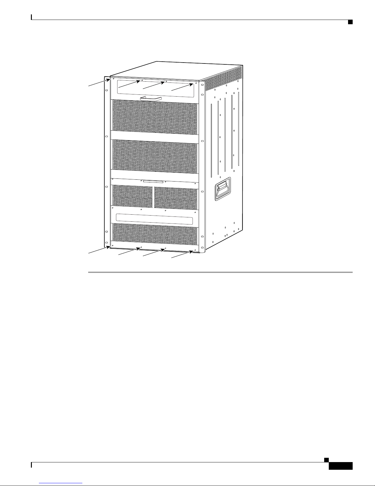
Figure 2 Installing the Panel Safety Cover
Replacing the Fan Tray
Replacing the Fan Tray
This section describes how to remove and install the fan tray for the Catalyst 6509-NEB switch and
Cisco OSR-7609 Router. The standard fan tray (WS-C6509-NEB-FAN) must be removed and replaced
with the high-speed fan tray (WS-C6509-NEB-FAN2). A flat-blade or number 2 Phillips-head
screwdriver is required to perform this procedure.
105071
78-16162-02
Catalyst 6509-NEB Switch and Cisco OSR-7609 Router Upgrade Note
7
Page 8

Replacing the Fan Tray
Removing the Fan Tray
Warning
When removing the fan tray, keep your hands and fingers away from the spinning fan blades. Let the
fan blades completely stop before you remove the fan tray.
Statement 258
To remove the standard fan tray (WS-C6509-NEB-FAN), follow these steps:
Step 1 Use a flat-blade or number 2 Phillips-head screwdriver to loosen the two captive installation screws on
the fan tray by turning them counterclockwise. (See Figure 3.)
Figure 3 Removing the Fan Tray
Captive installation
screw
SUPERVISO
FAN
STATUS
Captive installation
screw
2
W
4
2
W
4
2
S
P
-
O
X
R
6
2
T
2
1
4
0
0
F
X
S
T
A
T
U
S
1
1
LIN
L
IN
K
K
2
2
L
IN
L
IN
K
K
3
3
L
IN
L
IN
K
K
4
4
L
IN
LIN
K
K
5
5
L
IN
L
IN
K
K
6
6
L
IN
L
IN
K
K
7
7
LIN
L
IN
K
K
8
8
L
IN
L
IN
K
K
9
9
L
IN
L
IN
K
K
1
0
1
0
LIN
L
IN
K
K
1
1
1
1
L
IN
L
IN
K
K
1
2
1
2
L
IN
L
IN
K
K
1
3
1
3
L
IN
L
IN
K
K
1
4
1
4
LIN
LIN
K
K
1
5
1
5
L
IN
L
IN
K
K
1
6
1
6
L
IN
L
IN
K
K
1
7
1
7
L
IN
LIN
K
K
1
8
1
8
L
IN
L
IN
K
K
1
9
1
9
L
IN
L
IN
K
K
2
0
2
0
L
IN
L
IN
K
K
2
1
2
1
L
IN
LIN
K
K
2
2
2
2
L
IN
LIN
K
K
2
3
2
3
L
IN
L
IN
K
K
2
4
2
4
L
IN
L
IN
K
K
8 PORT GIGABIT ETHERNET
W
P
S
-X
O
R
6
2
T
2
1
4
0
0
F
X
S
T
A
T
U
S
1
L
IN
K
2
L
IN
K
3
L
IN
K
4
L
IN
K
5
LIN
K
6
L
IN
K
7
L
IN
K
8
L
IN
K
9
L
IN
K
1
0
LIN
K
1
1
L
IN
K
1
2
LIN
K
1
3
LIN
K
1
4
LINK
1
5
LIN
K
1
6
L
IN
K
1
7
L
IN
K
1
8
LIN
K
1
9
L
IN
K
2
0
L
IN
K
2
1
L
IN
K
2
2
L
IN
K
2
3
LIN
K
2
4
LIN
K
WS-X6408
4
P
O
R
T
1
0
0
F
X
8 PORT GIGABIT ETHERNET
S
-X
6
2
2
4
S
TATU
S
1
L
IN
K
2
L
IN
K
3
L
IN
K
4
LIN
K
5
LI
NK
6
L
IN
K
7
LIN
K
8
LIN
K
9
LIN
K
1
0
LIN
K
1
1
LIN
K
1
2
L
IN
K
1
3
L
IN
K
1
4
L
IN
K
1
5
L
IN
K
1
6
L
IN
K
1
7
LIN
K
1
8
LIN
K
1
9
L
IN
K
2
0
L
IN
K
2
1
LIN
K
2
2
LIN
K
2
3
L
IN
K
2
4
L
IN
K
WS-X6408
S
T
S
A
T
T
A
U
T
S
U
S
1
1
L
IN
LIN
K
K
2
2
L
IN
LINK
K
3
3
L
IN
L
IN
K
K
4
4
LIN
L
IN
K
K
5
5
LIN
LIN
K
K
6
6
LIN
LINK
K
7
7
LIN
LINK
K
8
8
LIN
L
INK
K
8 PORT GIGABIT ETHERNET
S
T
A
T
LIN
K
L
IN
K
LINK
L
IN
K
LINK
LINK
LIN
K
LINK
WS-X6K-SUP2-2GE
SU
W
PERVISO
S-X6K-SUP2-2GE
WS-X6408
R2
S
T
R2
A
S
T
T
U
A
S
T
S
U
Y
S
S
S
T
Y
E
S
M
T
C
E
O
M
N
C
S
O
O
N
L
P
S
E
W
U
S
1
2
3
4
5
6
7
8
O
L
R
P
E
W
M
R
G
R
M
M
E
T
G
S
R
E
M
E
T
T
S
E
T
C
O
C
N
O
S
N
O
S
L
O
E
L
E
C
O
C
N
M
O
P
S
O
N
O
M
O
P
D
S
R
O
L
O
E
O
T
E
D
R
L
E
T
E
P
C
P
M
C
C
M
I
A
C
I
A
E
J
E
E
J
C
E
T
C
T
1
0
1
0
%
1
%
0
1
0
%
S
%
w
S
i
t
w
c
h
it
c
h
L
o
a
L
d
o
a
d
P
O
P
R
O
L
T
I
N
R
K
1
L
T
I
N
K
1
P
O
P
R
O
L
T
I
N
R
K
L
2
T
I
N
K
2
Step 2
Grasp the fan tray handle with one hand and pull the fan tray outward about 1 inch; rock it gently, if
necessary, to unseat the power connector from the backplane. Wait for the fans to stop spinning.
Step 3 Once the fans have stopped spinning, pull the fan tray out further and support the underside of the fan
tray with the other hand.
Step 4 Pull the fan tray clear of the chassis, and put it in a safe place.
Catalyst 6509-NEB Switch and Cisco OSR-7609 Router Upgrade Note
8
o
INPUT
FAN
OUTPUT
OK
OK
o
FAIL
INPUT
FAN
OUTPUT
OK
OK
FAIL
30696
78-16162-02
Page 9

Installing the High Speed Fan Tray
To install the high speed fan tray (WS-C6509-NEB-FAN2), follow these steps:
Step 1 Hold the fan tray with the fans facing down and the FAN FAIL LED on the right. (See Figure 4.)
Figure 4 Installing the High Speed Fan Tray
48V
IN
P
U
T 1
INPOUT P
G
R
T
N
-48V
D
C
G
N
D
W
S-C6500-NEB-FAN2
Captive installation
screw
OW
ER
O
O
D
L
IN
K
L
IN
K
LI
N
K
L
IN
K
L
IN
K
L
IN
K
L
IN
K
L
IN
K
L
IN
K
L
IN
K
L
IN
K
L
IN
K
L
IN
K
L
IN
K
L
IN
K
L
IN
K
L
IN
K
LIN
K
L
IN
K
LIN
K
LIN
K
LIN
K
L
IN
K
LIN
K
HIGH SPEED FAN
2
4
P
O
R
T
1
0
0
F
X
1
LI
N
2
L
IN
3
L
IN
4
L
IN
5
L
IN
6
L
IN
K
7
L
IN
K
8
LIN
K
9
L
IN
K
1
0
L
IN
K
11
L
IN
K
1
2
L
IN
K
1
3
L
IN
K
1
4
L
IN
K
1
5
L
IN
K
1
6
L
IN
K
1
7
L
IN
K
1
8
L
IN
K
1
9
L
IN
K
2
0
L
IN
K
2
1
L
IN
K
2
2
L
IN
K
2
3
L
IN
K
24
L
IN
K
W
S
-
X
6
2
2
4
S
T
A
T
U
S
1
K
2
K
3
K
4
K
5
K
6
7
8
9
1
0
1
1
12
1
3
1
4
1
5
1
6
1
7
1
8
1
9
2
0
2
1
22
2
3
24
Captive installation
screw
2
W
4
P
S
-X
O
R
6
2
T
2
1
4
0
0
F
X
S
T
A
T
U
S
1
L
IN
K
2
L
IN
K
3
L
IN
K
4
L
IN
K
5
L
IN
K
6
L
IN
K
7
L
IN
K
8
L
IN
K
9
L
IN
K
1
0
L
IN
K
1
1
L
IN
K
1
2
L
IN
K
1
3
L
IN
K
1
4
L
IN
K
1
5
L
IN
K
1
6
L
IN
K
1
7
L
IN
K
1
8
L
IN
K
1
9
L
IN
K
2
0
LI
N
K
2
1
L
IN
K
2
2
LIN
K
2
3
LIN
K
2
4
LIN
K
4
8V
IN
PU
2
4
P
O
R
T
1
0
0
F
X
L
L
L
L
L
L
L
L
L
L
L
L
L
IN
L
IN
LIN
T
2
8 PORT GIGABIT ETHERNET
W
WS-X6408
8 PORT GIGABIT ETHERNET
S
-X
6
2
2
4
STATUS
S
T
S
A
T
T
A
U
T
S
F
A
N
F
A
I
L
IN
P
O
U
T
P
O
W
E
R
1
LIN
G
O
O
D
K
R
1
T
N
-48
V
D
C G
N
D
L
2
IN
LIN
LI
K
N
K
K
3
LIN
K
4
L
IN
K
2
5
LIN
LIN
L
IN
K
K
K
6
LIN
K
7
L
IN
K
3
8
L
L
IN
LI
IN
K
NK
K
9
L
IN
K
1
0
IN
K
1
4
1
LINK
IN
L
INK
K
1
2
IN
K
1
3
IN
K
1
4
5
LIN
IN
LINK
K
K
1
5
IN
K
1
6
IN
K
1
7
6
IN
LI
K
LIN
NK
K
1
8
IN
K
1
9
IN
K
2
0
7
IN
LINK
K
LINK
2
1
IN
K
2
2
K
2
3
8
K
LIN
LIN
K
K
2
4
K
Replacing the Fan Tray
SUPERVISOR2
W
SUPER
W
S-X6K-SUP2-2GE
S-X6K-SUP2-2G
WS-X6408
8 PORT GIGABIT ETHERNET
U
S
1
L
IN
K
2
LIN
K
3
LINK
4
LINK
5
L
IN
K
6
LIN
K
7
LINK
8
LIN
K
VISOR2
WS-X6408
S
T
A
S
T
T
U
A
S
T
S
U
Y
S
S
S
T
Y
E
S
M
E
T
C
E
O
M
N
C
S
S
T
A
T
O
O
N
L
P
S
E
W
U
S
1
2
3
4
5
6
7
8
O
L
R
P
E
W
M
R
G
R
M
M
E
T
G
S
R
E
M
E
T
T
S
E
T
C
O
C
N
O
S
N
O
S
L
O
E
L
E
C
O
C
N
M
O
P
S
O
N
O
M
O
P
D
S
R
O
L
O
E
O
T
E
D
R
L
E
T
E
P
C
P
M
C
C
M
I
A
C
I
A
E
J
E
E
J
C
E
T
C
T
1
0
1
0
%
1
%
0
1
0
%
S
%
w
S
it
w
c
h
it
c
h
L
o
L
a
d
o
a
d
P
O
P
R
O
L
T
I
N
R
K
1
L
T
I
N
K
1
P
O
P
R
O
L
T
I
N
R
K
L
2
T
I
N
K
2
78-16162-02
Step 2
o
INPUT
FAN
OUTPUT
OK
OK
Place the fan tray into the front chassis cavity so that it rests on the chassis, and then lift the fan tray up
o
FAIL
INPUT
FAN
OUTPUT
OK
OK
FAIL
105068
slightly, aligning the top and bottom chassis guides.
Step 3 Push the fan tray into the chassis until the power connector seats in the backplane and the captive
installation screws make contact with the chassis.
Step 4 Use a flat-blade or number 2 Phillips-head screwdriver to tighten the captive installation screws.
Step 5 Proceed to the “Replacing the Power Supply” section on page 10 to replace the power supply.
Catalyst 6509-NEB Switch and Cisco OSR-7609 Router Upgrade Note
9
Page 10

Replacing the Power Supply
Replacing the Power Supply
Note DC-input systems—See the “Connecting Site Power to the Fan Tray for DC-Input Systems” section on
page 15 to connect site power to the high speed fan tray.
This section describes how to remove and install AC-input power supplies for the Catalyst 6509-NEB
switch and Cisco OSR-7609 router.
Removing an AC-Input Power Supply
Warning
Hazardous voltage or energy is present on the backplane when the system is operating. Use caution
when servicing.
Statement 1034
To remove an AC-input power supply, follow these steps:
Step 1 Loosen the captive installation screw. (See Figure 5.)
Caution Use both hands to install and remove power supplies. Each Catalyst 6500 series AC-input power supply
weighs between 22 pounds (9.9 kg) and 28 pounds (12.6 kg).
Step 2 Grasp the power supply handle with one hand, and slide the power supply part of the way out of the
chassis. Place your other hand underneath the power supply, as shown in Figure 6, and slide the power
supply completely out of the chassis.
Figure 5 AC-Input Power Supply Front Panel
AC power
connection
Cable
retention
device
I
Powe r
switch
Catalyst 6509-NEB Switch and Cisco OSR-7609 Router Upgrade Note
0
Captive installation
10
screw
INPUT
FAN
OUTPUT
O
K
OK
FAIL
Status LEDs
16029
78-16162-02
Page 11

Figure 6 Removing an AC-Input Power Supply
48V IN
P
U
T
1
FAN
STATUS
R
W
S-C6500-NEB-FAN2
8 PORT OC3 POS MM
STATUS
2
LINK
1
2
LINK
4
LINK
3
4
LINK
RESET
INPOUT P
OW
ER
G
O
O
D
T
N
-48
VD
C
G
N
D
OSM-8OC3-POS MM
8 PORT OC3 POS MM
OSM-8OC3-POS MM
O
C
1
2
P
O
S
TATUS
S
M
M
1
2
1
LINK
LIN
K
1
1
2
LINK
LIN
K
2
3
4
3
LINK
L
IN
K
3
3
4
LINK
L
INK
4
CARRIER
LINK
CARRIER
ALARM
LINK
ALARM
RESE
T
A
LA
1
1
2
2
P
O
3
3
4
A
4
L
5
5
6
6
P
O
R
7
7
C
A
A
L
A
R
8
8
P
O
R
T
C
A
A
L
A
R
HIGH SPEED FAN
O
S
M
W
O
W
S
-4
S
W
0
C
C
I
T
6
1
C
S
5
2
TA
H
0
-P
0
T
O
F
-
U
S
A
S
S
F
-
B
M
M
R
M
I
C
M
D
2
1
S
L
T
ATU
S
A
C
T
IV
E
4
3
R
E
S
E
T
C
A
R
R
IE
R
M
R
A
C
T
I
V
E
R
T
X
X
R
X
R
T
1
T
X
C
A
R
R
A
IE
R
M
R
A
C
T
I
V
E
R
T
X
X
R
X
T
2
T
X
R
R
IE
M
R
A
S
N
C
EL
EX
T
EC
I
T
V
E
T
R
T
X
X
R
X
3
T
X
R
R
IE
M
R
A
C
T
I
V
E
R
T
X
X
R
X
T
X
O
S
O
C
S
S
W
1
C
M
-
2
1
C
I
P
T
-4
2
6
P
C
O
5
0
H
0
C
O
S
0
1
M
S
F
-
S
2
S
M
A
T
-P
M
F
AT
B
M
M
O
U
R
S
S
I
C
-M
M
M
D
ST
L
A
T
US
2
1
A
CT
L
IVE
IN
LIN
K
K
1
1
LIN
LIN
K
K
2
2
4
3
LIN
LIN
K
K
3
3
L
IN
LIN
K
K
4
4
R
E
S
E
T
C
A
A
R
L
R
A
IE
R
M
R
A
C
T
IV
E
R
T
X
X
R
X
P
O
R
T
1
T
X
C
A
A
R
L
R
A
IE
R
M
R
A
C
T
IV
E
R
T
X
X
R
X
P
O
R
T
2
T
X
C
A
A
R
L
R
A
A
I
R
E
M
R
SE
NE
LE
XT
CT
A
C
T
IV
E
R
T
X
X
R
X
P
O
P
R
T
3
T
X
C
A
A
R
L
R
A
A
IE
R
M
R
A
C
T
IV
E
R
T
X
X
R
X
T
X
48
V
IN
P
U
T 2
F
A
N
F
A
IL
IN
P
O
U
T
P
O
W
E
R
G
O
O
D
R
T
N
-48
VD
C
G
N
D
O
S
SUPERVISOR2
M
WS-X6K-SUP2-2GE
SUPERVISOR2
-4
WS-X6K-SUP2-2GE
0
C
1
ST
2
-
A
P
T
O
US
S
S
-M
T
ATU
S
TAT
M
S
US
SYS
SY
TE
2
4
R
E
S
E
T
C
A
A
R
L
R
A
I
R
E
M
R
R
X
P
O
R
T
1
C
A
A
R
L
R
A
IE
R
M
R
R
X
P
O
R
T
2
C
A
R
L
R
A
IE
R
M
R
R
T
X
O
R
T
3
C
A
R
L
R
A
IE
R
M
R
R
T
X
S
1
M
TE
C
M
ON
CO
S
NS
OL
PW
E
O
L
P
R
E
W
M
R
GM
R
M
E
GM
T
R
S
ET
E
T
SE
T
C
O
C
N
O
S
N
O
S
L
O
E
L
E
3
C
O
C
N
O
M
P
S
N
O
M
O
O
P
S
D
O
R
O
L
O
E
T
E
D
R
L
E
T
E
L
I
N
K
A
C
T
IV
E
P
C
P
M
C
T
C
M
X
IA
C
IA E
R
X
E
J
T
E
X
J
C
E
T
C
T
A
C
T
IV
E
T
X
R
X
T
X
1
0
1
1
0
%
0
%
1
0
%
%
S
w
S
it
w
c
itc
h
A
C
T
IV
E
X
R
X
T
X
A
C
T
IV
E
X
R
X
T
X
h
L
L
o
a
o
d
a
d
P
O
P
R
O
T
R
L
I
1
N
T
L
K
I
N
1
K
P
O
P
R
O
L
T
R
I
N
2
T
K
2
Replacing the Power Supply
105074
I
0
IN
P
U
T
F
A
N
O
U
T
P
U
T
O
K
O
K
F
A
IL
78-16162-02
Catalyst 6509-NEB Switch and Cisco OSR-7609 Router Upgrade Note
11
Page 12

Replacing the Power Supply
e
Installing the 3000 W AC-Input Power Supply
Caution Use both hands to install and remove power supplies. Each Catalyst 6500 series AC-input power supply
weighs between 22 pounds (9.9 kg) and 28 pounds (12.6 kg).
To install the 3000 W AC-input power supply, follow these steps:
Step 1 Ensure that the system (earth) ground connection has been made. For ground connection instructions,
refer to the installation guide for your hardware platform.
Step 2 Verify that the power switch is in the Off (0) position on the power supply you are installing.
(See Figure 7.)
Figure 7 3000 Watt AC-Input Power Supply Front Panel
AC power
connection
Step 3
Cable
tention
device
Power
switch
N
I
O
110-120V - 15A
200-240V - 15A
60/50HZ
L
L
A
T
S
N
U
R
I
OUTPUT 42V /17A
42V /17A
INPUT
FAN
OUTPUT
OK
OK
FAIL
OK
+
105069
External power
Captive installation
Status LEDs (3)
connector cover
screw
Grasp the power supply handle with one hand. Place your other hand underneath the power supply, as
shown in Figure 8. Slide the power supply into the power supply bay. Make sure that the power supply
is fully seated in the bay.
Catalyst 6509-NEB Switch and Cisco OSR-7609 Router Upgrade Note
12
78-16162-02
Page 13

Figure 8 Installing the 3000 W Power Supply
4
8V
IN
P
U
T
1
FAN
STATUS
R
T
N
-4
8V
WS-C6500-NEB-FAN2
8 PORT OC3 POS MM
STATUS
2
1
LINK
1
2
LINK
4
3
LINK
3
4
LINK
CARRIER
ALARM
RE
SET
1
2
3
4
5
6
7
8
INPOUT
POWER
G
O
O
D
D
C
G
N
D
OSM-8OC3-POS MM
8 PORT OC3 POS MM
OSM-8OC3-POS MM
O
C
1
2
P
O
STATUS
S
M
M
2
1
LINK
L
INK
1
1
2
LINK
L
INK
2
4
3
LINK
L
INK
3
3
4
LINK
L
IN
K
4
LINK
CARRIER
LINK
ALARM
RESET
1
2
3
4
5
6
P
7
A
L
8
P
O
A
L
HIGH SPEED FAN
O
S
M
W
O
W
S
-4
S
W
0
C
C
I
T
6
1
C
ST
5
2
H
0
-
A
P
0
TU
O
F
S
A
S
S
F
-M
B
M
R
M
I
C
M
D
2
1
S
L
T
AT
US
AC
T
IVE
4
3
R
E
S
E
T
C
A
A
R
L
R
A
IE
R
M
R
A
C
T
IV
E
R
T
X
X
R
X
P
O
R
T
1
T
X
C
A
A
R
L
R
A
IE
R
M
R
A
C
T
IV
E
R
T
X
X
R
X
O
R
T
2
T
X
C
A
R
R
A
IE
R
M
R
A
SE
NE
C
T
LE
XT
IV
C
E
T
R
T
X
X
R
X
R
T
3
T
X
C
A
R
R
A
I
R
E
M
R
A
C
T
IV
E
R
T
X
X
R
X
T
X
O
S
O
C
S
S
W
1
C
M
-
2
1
C
I
P
T
-4
2
6
P
C
O
5
0
H
0
C
O
S
0
1
M
S
F
-
S
2
S
M
A
T
-P
M
F
AT
B
M
M
O
US
R
S
I
C
-
M
M
M
D
S
L
TAT
U
2
1
S
AC
T
LIN
IV
E
L
IN
K
K
1
1
L
IN
LIN
K
K
2
2
4
3
LI
NK
LIN
K
3
3
LIN
LIN
K
K
4
4
R
E
S
E
T
C
A
A
R
L
R
A
A
IE
R
M
R
A
C
T
IV
E
R
T
X
X
R
X
P
O
P
R
O
T
1
T
X
C
A
A
R
L
R
A
A
L
I
R
E
M
R
A
C
T
IV
E
R
T
X
X
R
X
P
O
P
R
O
T
2
T
X
C
A
C
A
R
L
R
A
A
L
IE
R
A
M
R
S
N
E
EX
LEC
T
A
T
C
T
IV
E
R
T
X
X
R
X
P
O
P
R
O
T
R
3
T
T
X
C
A
C
A
R
L
A
R
A
A
L
IE
R
A
M
R
R
A
C
T
IV
E
R
T
X
X
R
X
T
X
4
8
V
IN
PU
T
2
F
A
N
F
A
I
L
IN
P
O
U
T
P
O
W
E
R
G
O
O
D
R
T
N
-4
8V
D
C
G
N
D
O
S
SUPERVISOR2
M
WS-X6K-SUP2-2GE
SUPERVISOR2
-
WS-X6K-SUP2-2GE
4
0
C
1
S
2
T
-
AT
P
O
U
S
S
ST
-M
AT
S
TA
M
U
S
TU
S
Y
S
ST
SY
EM
2
4
R
E
S
E
T
C
A
R
L
R
A
IE
R
M
R
R
X
R
T
1
C
A
R
R
A
IE
R
M
R
R
X
R
T
2
A
R
R
IE
R
M
R
R
T
X
X
3
R
R
IE
M
R
R
T
X
X
ST
1
C
EM
ON
C
O
SOL
N
SO
P
E
W
L
P
R
E
W
MG
R
M
RE
M
G
T
RES
SET
MT
ET
C
O
C
N
O
S
N
O
S
L
O
E
L
E
3
C
O
C
N
O
M
P
S
N
O
M
O
O
P
S
D
O
R
O
L
O
E
T
E
D
R
L
E
T
E
L
I
N
K
A
C
T
IV
E
P
C
P
M
C
T
C
M
X
IA E
C
I
A
R
X
J
T
E
E
X
J
C
E
T
C
T
A
C
T
IV
E
T
X
R
X
T
X
1
0
1
1
0
%
0
%
1
0
%
%
S
w
S
itc
w
itc
h
A
L
C
T
IV
E
R
X
T
X
A
C
T
IV
E
R
X
T
X
h
L
o
a
o
d
a
d
P
O
P
R
O
T
R
L
I
N
T
1
L
K
I
N
1
K
P
O
P
R
O
L
T
R
I
N
2
T
K
2
Connecting Power to the Fan Tray
110-120V - 15A
200-240V - 15A
60/50HZ
L
I
L
A
T
S
N
N
U
I
Step 4
R
O
INPUT
FAN
OUTPUT
OK
OK
FAIL
Tighten the power supply captive installation screw. (See Figure 7.)
OUTPUT 42V
42V
O
K
m
/
m
+
Step 5 If you have a redundant power supply, install it now following the steps in this section.
Step 6 Proceed to the “Connecting Power to the Fan Tray” section on page 13 to connect power to the high
speed fan tray.
Connecting Power to the Fan Tray
The high-speed fan tray requires external power, either from the 3000 W AC-input power supply or
from an external DC power source. The fan tray ships with power wires secured at each terminal block.
If you are using the 3000 W AC-input power supply, use the supplied cables to connect the fan tray wires
to the power supply.
If you are using a DC-input power supply, remove the wires from the fan tray and connect directly to a
DC power source.
105070
The following sections describe how to connect power to the fan tray:
• Installing the Fan Tray Power Cable for AC-Input Systems, page 14
• Connecting Site Power to the Fan Tray for DC-Input Systems, page 15
78-16162-02
Catalyst 6509-NEB Switch and Cisco OSR-7609 Router Upgrade Note
13
Page 14

Connecting Power to the Fan Tray
Installing the Fan Tray Power Cable for AC-Input Systems
Note The fan tray ships with power wires secured at each terminal block. Use these wires to connect the fan
tray to the 3000 W AC-input power supply using the supplied cables. If you have redundant power
supplies, repeat the steps in this section for the redundant power supply.
To connect the high speed fan tray to the 3000 W AC-input power supply, follow these steps:
Step 1 Connect the female end of the supplied power cable (see Figure 9) to the fan tray wire connector. Press
the two ends together until you hear a click.
Figure 9 Cable Connectors
Step 2
To fan cable To power supply
On the power supply, loosen the thumb screw on the external power connector cover and lift up the cover.
105076
(See Figure 10.)
Figure 10 External Power Connector Cover
1 2
OUTPUT 42V /17A
42V /17A
OK
OUTPUT 42V /17A
42V /17A
OK
+
105083
Step 3
Connect the male end of the supplied power cable to the female end of the external power connector on
the power supply until you hear a click.
Step 4 If you have redundant power supplies, repeat the steps in this section for the redundant power supply.
Catalyst 6509-NEB Switch and Cisco OSR-7609 Router Upgrade Note
14
78-16162-02
Page 15

Connecting Site Power to the Fan Tray for DC-Input Systems
Note To provide redundancy, you may choose to connect each fan terminal block to a separate power source.
Note Each input of the fan tray is rated 10 A @ -40 to -60 VDC.
Connecting Power to the Fan Tray
Warning
This product requires short-circuit (overcurrent) protection, to be provided as part of the building
installation. Install only in accordance with national and local wiring regulations.
Warning
Before performing any of the following procedures, ensure that power is removed from the DC circuit.
Statement 1003
To connect the high speed fan tray to an external DC power source, follow these steps:
Step 1 Locate the terminal block covers on the fan tray. (See Figure 11.)
Figure 11 Terminal Block Covers on Fan Tray
Terminal block covers
48V INPUT 1
RTN -48VDC GND
WS-C6500-NEB-FAN2
IN
GOOD
P
U
T
P
O
W
E
R
HIGH SPEED FAN
F
A
N
F
A
IL
IN
P
U
T
P
O
W
E
GOOD
RTN -48VDC GND
48V INPUT 2
R
Statement 1045
105081
Step 2
The terminal block cover is held in place by two clips inserted into the fan tray front panel. Press the
bottom of the terminal block cover, lift the cover up, and remove the cover. (See Figure 12.)
78-16162-02
Catalyst 6509-NEB Switch and Cisco OSR-7609 Router Upgrade Note
15
Page 16

Connecting Power to the Fan Tray
Figure 12 Removing the Terminal Block Cover
Terminal block
cover
105082
Step 3
Step 4
With a flat blade screwdriver, disconnect the input wires from the terminal block. (See Figure 13.)
Figure 13 Input Wire Connections on the Terminal Block
48V INPUT 1
+
GND
INPUT POWER
GOOD
RTN -48vdc GND
105084
Connect the DC-input wires to the terminal block (see Figure 14) in this order:
• Ground
• Negative (-)
• Positive (+)
Catalyst 6509-NEB Switch and Cisco OSR-7609 Router Upgrade Note
16
78-16162-02
Page 17

Figure 14 DC-Input Wire Connections on the Terminal Block
48V INPUT 1
+
GND
INPUT POWER
GOOD
RTN -48vdc GND
105085
Replacing the Supervisor Engine
Warning
Step 5 After ensuring that all wire connections are secure, reinstall the terminal block cover.
When installing or replacing the unit, the ground connection must always be made first and
disconnected last.
Statement 1046
Replacing the Supervisor Engine
Before you can power up the system, you need to remove the supervisor engine from slot 1 (if a
redundant supervisor engine is present, remove it from slot 2) and install the Supervisor Engine 720 or
the Supervisor Engine 32 in slot 5 or 6.
Removing the Supervisor Engine
This section describes how to remove an existing supervisor engine from a chassis slot.
To remove a supervisor engine from the chassis, perform these steps:
Step 1 Disconnect any network interface cables attached to the supervisor engine.
Step 2 Verify that the captive installation screws on all of the modules in the chassis are tight. This step assures
that the space created by the removed supervisor engine is maintained.
Note If the captive installation screws are loose, the electromagnetic interference (EMI) gaskets on
the installed modules will push the modules toward the open slot, reducing the opening size and
making it difficult to install the replacement module.
78-16162-02
Catalyst 6509-NEB Switch and Cisco OSR-7609 Router Upgrade Note
17
Page 18

Replacing the Supervisor Engine
Step 3 Loosen the two captive installation screws on the supervisor engine.
Step 4 Place your thumbs on the ejector levers located at the top and bottom of the supervisor engine, and
simultaneously rotate the levers outward to unseat the supervisor engine from the backplane connector.
Step 5 Grasp the edges of the supervisor engine, and slide the supervisor engine straight out of the slot. Do not
touch the module circuitry.
Step 6 Place the supervisor engine on an antistatic mat or antistatic foam.
Step 7 If the slot is to remain empty, install a module filler plate to keep dust out of the chassis and to maintain
proper airflow through the chassis.
Installing the Supervisor Engine
This section describes how to install the Supervisor Engine 720 or the Supervisor Engine 32 in the
Catalyst 6509-NEB switch and the Cisco OSR-7609 Router.
Caution To prevent ESD damage, handle modules by the carrier edges only.
Note The Supervisor Engine 720 or Supervisor Engine 32 must be installed in slot 5 or 6 of the Catalyst
6509NEB or Cisco OSR7609 chassis.
To install the supervisor engine in the chassis, perform these steps:
Step 1 Choose a slot for the supervisor engine.
Step 2 Verify that there is enough clearance to accommodate any interface equipment that you will connect
directly to the supervisor engine ports. If possible, place modules between empty slots that contain only
module filler plates.
Step 3 Verify that the captive installation screws are tightened on all modules installed in the chassis. This
assures that the EMI gaskets on all modules are fully compressed in order to maximize the opening space
for the new module or the replacement module.
Note If the captive installation screws are loose, the EMI gaskets on the installed modules will push
adjacent modules toward the open slot, reducing the opening size and making it difficult to
install the replacement module.
Step 4 Remove the module filler plate by removing the two Phillips pan-head screws from the filler plate. To
remove a module, see the “Removing the Supervisor Engine” section on page 17.
Step 5 Fully open both ejector levers on the supervisor engine. (See Figure 15.)
Step 6 Position the supervisor engine in the slot. (See Figure 15.) Make sure that you align the sides of the
module carrier with the slot guides on the top and bottom of the slot.
Step 7 Carefully slide the supervisor engine into the slot until the EMI gasket along the right edge of the
supervisor engine makes contact with the module in the slot adjacent to it and both ejector levers have
closed to approximately 45 degrees with respect to the supervisor engine faceplate. (See Figure 16.)
Catalyst 6509-NEB Switch and Cisco OSR-7609 Router Upgrade Note
18
78-16162-02
Page 19

Replacing the Supervisor Engine
4
3
6
Step 8 Using the thumb and forefinger of each hand, grasp the two ejector levers and exert a slight pressure to
the left, deflecting the module approximately 0.040 inches (1 mm) to create a small gap between the
supervisor engine's EMI gasket and the module adjacent to it. (See Figure 16.)
Caution Do not exert too much pressure on the ejector levers. They will bend and be damaged.
Step 9 While pressing on the ejector levers, simultaneously close them to fully seat the supervisor engine in the
backplane connector. The ejector levers are fully closed when they are flush with the supervisor engine
faceplate. (See Figure 17.)
Step 10 Tighten the two captive installation screws on the supervisor engine.
Note Make sure the ejector levers are fully closed before tightening the captive installation screws.
Figure 15 Positioning the Supervisor Engine in the Chassis
Ejector lever fully
extended
W
S-C6500-NEB-FAN2
4
8
V
IN
P
U
T
1
I
N
P
O
U
T
P
O
W
E
G
O
O
D
R
T
N
-4
8
V
D
C
G
N
D
24 PO
WS-X6224
RT 100FX
HIGH SPEED FAN
R
4
8
V
IN
P
U
T
2
FAN FA
IL
INPO
UT PO
WER
G
O
O
D
R
T
N
-4
8
V
D
C
G
N
D
EMI
gasket
EMI
gasket
1
1
0
1
2
0
V
1
5
A
2
0
0
2
4
0
V
1
5
A
6
0
/5
0
H
Z
L
I
L
A
T
S
N
N
I
U
R
O
INPUT
FAN
OUTPUT
OK
OK
FAIL
1
1
0
1
2
0
V
1
5
A
2
0
0
-2
4
0
V
1
5
A
6
0
/5
0
H
Z
L
I
L
A
T
S
N
N
I
U
m
OUTPUT 42V
/
R
m
42
V
OK
O
+
m
OUTPUT 42V
/
m
4
2V
OK
INPUT
FAN
OUTPUT
OK
OK
FAIL
+
105092
Insert module
between slot guides
78-16162-02
Catalyst 6509-NEB Switch and Cisco OSR-7609 Router Upgrade Note
19
Page 20

Replacing the Supervisor Engine
SWITCH FABIRD MDL
WS-C6500-SFM
STATUS
ACTIVE
Figure 16 Clearing the EMI Gasket in the Chassis
Press left
R
WS-C6500-NEB-FAN
Gap between the module
EMI gasket and the
module above it
1 mm
4
8
V
IN
P
U
T
1
I
N
P
O
U
T
P
O
W
G
O
O
D
T
N
-4
8
V
D
C
G
N
D
2
HIGH SPEED FAN
E
R
24 PORT 100FX
WS-X6224
24 PORT 100FX
4
8
V
IN
P
U
T
2
FAN
FAIL
INP
OU
T
POWER
G
O
O
D
R
T
N
-4
8
V
D
C
G
N
D
Press left
1
1
0
1
2
0
V
1
5
A
2
0
0
2
4
0
V
-
1
5
A
6
0
/5
0
H
Z
L
I
L
A
T
S
N
N
I
U
R
O
INPUT
FAN
OUTPUT
OK
OK
FAIL
1
1
0
1
2
0
V
1
5
A
2
0
0
2
4
0
V
1
5
A
6
0
/
5
0
H
Z
L
I
L
A
T
S
N
N
I
U
m
OUTPUT 42V
/
R
m
4
2V
OK
O
+
m
OUTPUT 42V
/
m
4
2V
OK
INPUT
FAN
OUTPUT
OK
OK
FAIL
+
105093
Catalyst 6509-NEB Switch and Cisco OSR-7609 Router Upgrade Note
20
78-16162-02
Page 21

Figure 17 Ejector Lever Closure in the Chassis
Powering Up the System
W
S-C6500-NE
48V INPUT 1
RTN -48VDC G
B-FAN2
INPOUT POWER
GOOD
ND
All ejector levers flush
with module faceplate
HIGH SPEED FAN
48V INPUT 2
F
A
N
F
A
IL
I
N
P
O
U
T
P
O
W
E
R
GOOD
RTN -48VDC GND
105094
Powering Up the System
This section describes how to power up the system.
• AC-Input Systems, page 21
• DC-Input Systems, page 22
AC-Input Systems
To power up your AC-input system, follow these steps:
Step 1 Plug the power cord into the power supply, and tighten the screw on the cable retention device.
Step 2 Connect the other end of the power cord to an AC-input power source.
Caution In a system with dual power supplies, connect each power supply to a separate input source. In case of
a power source failure, the second source will most likely still be available.
Step 3 Turn the power switch to the On (|) position on the power supply. Switching the power switch to On also
engages a pawl that locks the power supply in the bay.
78-16162-02
Catalyst 6509-NEB Switch and Cisco OSR-7609 Router Upgrade Note
21
Page 22

Verifying Installation
DC-Input Systems
To power up your DC-input system, follow these steps:
Step 1 Remove the tape from the circuit breaker switch handle, and restore power by moving the circuit breaker
switch handle to the On (|) position.
Step 2 Turn the power switch to the On (|) position on the power supply. Turning the power switch on also
engages a pawl that locks the power supply in the chassis.
Verifying Installation
After you have powered up the switch, verify the operation of the newly installed hardware as follows:
Step 1 Verify power supply operation by checking that the power supply front panel LEDs are in these states:
• INPUT OK LED is green
• FAN OK LED is green
• OUTPUT FAIL LED is not lit
• 42V LED is green
If the LEDs indicate a power problem, refer to the installation guide for your hardware platform for
troubleshooting information.
Step 2 Verify the high speed fan tray operation by checking that the fan tray LEDs are in these:
• INPUT POWER GOOD LED is green (there is one LED for each power input; if both inputs are
used, verify both LEDs)
• FAN FAIL LED is green
If the LEDs indicate a problem, refer to the installation guide for your hardware platform for
troubleshooting information.
Step 3 Verify that the supervisor engine STATUS LED is lit. Check the STATUS LED periodically. If the
STATUS LED changes from orange to green, the supervisor engine has successfully completed the boot
process and is now online. If the STATUS LED remains orange or turns red, the supervisor engine has
not successfully completed the boot process and may have encountered an error.
Catalyst 6509-NEB Switch and Cisco OSR-7609 Router Upgrade Note
22
78-16162-02
Page 23

Related Documentation
Related Documentation
For additional information on Catalyst 6500 series switches and command-line interface (CLI)
commands, refer to the following publications:
• Regulatory Compliance and Safety Information for the Catalyst 6500 Series Switches
• Regulatory Compliance and Safety Information for the Cisco 7600 Series Routers
• Catalyst 6500 Series Switch Installation Guide
• Cisco 7609 Router Installation Guide
Obtaining Documentation and Submitting a Service Request
For information on obtaining documentation, submitting a service request, and gathering additional
information, see the monthly What’s New in Cisco Product Documentation, which also lists all new and
revised Cisco technical documentation, at:
http://www.cisco.com/en/US/docs/general/whatsnew/whatsnew.html
Subscribe to the What’s New in Cisco Product Documentation as a Really Simple Syndication (RSS) feed
and set content to be delivered directly to your desktop using a reader application. The RSS feeds are a free
service and Cisco currently supports RSS Version 2.0.
This document is to be used in conjunction with the documents listed in the “Related Documentation” section.
CCVP, the Cisco logo, and Welcome to the Human Network are trademarks of Cisco Systems, Inc.; Changing the Way We Work, Live, Play, and Learn is
a service mark of Cisco Systems, Inc.; and Access Registrar, Aironet, Catalyst, CCDA, CCDP, CCIE, CCIP, CCNA, CCNP, CCSP, Cisco, the Cisco
Certified Internetwork Expert logo, Cisco IOS, Cisco Press, Cisco Systems, Cisco Systems Capital, the Cisco Systems logo, Cisco Unity,
Enterprise/Solver, EtherChannel, EtherFast, EtherSwitch, Fast Step, Follow Me Browsing, FormShare, GigaDrive, HomeLink, Internet Quotient, IOS,
iPhone, IP/TV, iQ Expertise, the iQ logo, iQ Net Readiness Scorecard, iQuick Study, LightStream, Linksys, MeetingPlace, MGX, Networkers,
Networking Academy, Network Registrar, PIX, ProConnect, ScriptShare, SMARTnet, StackWise, The Fastest Way to Increase Your Internet Quotient,
and TransPath are registered trademarks of Cisco Systems, Inc. and/or its affiliates in the United States and certain other countries.
All other trademarks mentioned in this document or Website are the property of their respective owners. The use of the word partner does not imply a
partnership relationship between Cisco and any other company. (0711R)
© 2004–2006 Cisco Systems, Inc. All rights reserved.
78-16162-02
Catalyst 6509-NEB Switch and Cisco OSR-7609 Router Upgrade Note
23
Page 24

Obtaining Documentation and Submitting a Service Request
Catalyst 6509-NEB Switch and Cisco OSR-7609 Router Upgrade Note
24
78-16162-02
 Loading...