

Page 1

Catalyst 4900 Series Switch Installation Guide
August 2008
Americas Headquarters
Cisco Systems, Inc.
170 West Tasman Drive
San Jose, CA 95134-1706
USA
http://www.cisco.com
Tel: 408 526-4000
800 553-NETS (6387)
Fax: 408 527-0883
Text Part Number: 78-18039-02
Page 2

THE SPECIFICATIONS AND INFORMATION REGARDING THE PRODUCTS IN THIS MANUAL ARE SUBJECT TO CHANGE WITHOUT
NOTICE. ALL STATEMENTS, INFORMATION, AND RECOMMENDATIONS IN THIS MANUAL ARE BELIEVED TO BE ACCURATE BUT
ARE PRESENTED WITHOUT WARRANTY OF ANY KIND, EXPRESS OR IMPLIED. USERS MUST TAKE FULL RESPONSIBILITY FOR
THEIR APPLICATION OF ANY PRODUCTS.
THE SOFTWARE LICENSE AND LIMITED WARRANTY FOR THE ACCOMPANYING PRODUCT ARE SET FORTH IN THE INFORMATION
PACKET THAT SHIPPED WITH THE PRODUCT AND ARE INCORPORATED HEREIN BY THIS REFERENCE. IF YOU ARE UNABLE TO
LOCATE THE SOFTWARE LICENSE OR LIMITED WARRANTY, CONTACT YOUR CISCO REPRESENTATIVE FOR A COPY.
The following information is for FCC compliance of Class A devices: This equipment has been tested and found to comply with the limits for a Class
A digital device, pursuant to part 15 of the FCC rules. These limits are designed to provide reasonable protection against harmful interference when
the equipment is operated in a commercial environment. This equipment generates, uses, and can radiate radio-frequency energy and, if not installed
and used in accordance with the instruction manual, may cause harmful interference to radio communications. Operation of this equipment in a
residential area is likely to cause harmful interference, in which case users will be required to correct the interference at their own expense.
The following information is for FCC compliance of Class B devices: The equipment described in this manual generates and may radiate
radio-frequency energy. If it is not installed in accordance with Cisco’s installation instructions, it may cause interference with radio and television
reception. This equipment has been tested and found to comply with the limits for a Class B digital device in accordance with the specifications in
part 15 of the FCC rules. These specifications are designed to provide reasonable protection against such interference in a residential installation.
However, there is no guarantee that interference will not occur in a particular installation.
Modifying the equipment without Cisco’s written authorization may result in the equipment no longer complying with FCC requirements for Class
A or Class B digital devices. In that event, your right to use the equipment may be limited by FCC regulations, and you may be required to correct
any interference to radio or television communications at your own expense.
You can determine whether your equipment is causing interference by turning it off. If the interference stops, it was probably caused by the Cisco
equipment or one of its peripheral devices. If the equipment causes interference to radio or television reception, try to correct the interference by
using one or more of the following measures:
• Turn the television or radio antenna until the interference stops.
• Move the equipment to one side or the other of the television or radio.
• Move the equipment farther away from the television or radio.
• Plug the equipment into an outlet that is on a different circuit from the television or radio. (That is, make certain the equipment and the television
or radio are on circuits controlled by different circuit breakers or fuses.)
Modifications to this product not authorized by Cisco Systems, Inc. could void the FCC approval and negate your authority to operate the product.
The Cisco implementation of TCP header compression is an adaptation of a program developed by the University of California, Berkeley (UCB) as
part of UCB’s public domain version of the UNIX operating system. All rights reserved. Copyright © 1981, Regents of the University of California.
NOTWITHSTANDING ANY OTHER WARRANTY HEREIN, ALL DOCUMENT FILES AND SOFTWARE OF THESE SUPPLIERS ARE
PROVIDED “AS IS” WITH ALL FAULTS. CISCO AND THE ABOVE-NAMED SUPPLIERS DISCLAIM ALL WARRANTIES, EXPRESSED
OR
IMPLIED, INCLUDING, WITHOUT LIMITATION, THOSE OF MERCHANTABILITY, FITNESS FOR A PARTICULAR PURPOSE AND
NONINFRINGEMENT OR ARISING FROM A COURSE OF DEALING, USAGE, OR TRADE PRACTICE.
IN NO EVENT SHALL CISCO OR ITS SUPPLIERS BE LIABLE FOR ANY INDIRECT, SPECIAL, CONSEQUENTIAL, OR INCIDENTAL
DAMAGES, INCLUDING, WITHOUT LIMITATION, LOST PROFITS OR LOSS OR DAMAGE TO DATA ARISING OUT OF THE USE OR
INABILITY TO USE THIS MANUAL, EVEN IF CISCO OR ITS SUPPLIERS HAVE BEEN ADVISED OF THE POSSIBILITY OF SUCH
DAMAGES.
Page 3

CCDE, CCENT, Cisco Eos, Cisco Lumin, Cisco Nexus, Cisco StadiumVision, Cisco TelePresence, the Cisco logo, DCE, and Welcome to the
Human Network are trademarks; Changing the Way We Work, Live, Play, and Learn and Cisco Store are service marks; and Access Registrar,
Aironet, AsyncOS, Bringing the Meeting To You, Catalyst, CCDA, CCDP, CCIE, CCIP, CCNA, CCNP, CCSP, CCVP, Cisco, the Cisco
Internetwork Expert logo, Cisco
Without Limitation, EtherFast, EtherSwitch, Event Center, Fast Step, Follow Me Browsing, FormShare, GigaDrive, HomeLink, Internet Quotient,
IOS, iPhone, iQ Expertise, the iQ logo, iQ
MeetingPlace, MeetingPlace Chime Sound, MGX, Networkers, Networking Academy, Network Registrar, PCNow, PIX, PowerPanels, ProConnect,
ScriptShare, SenderBase, SMARTnet, Spectrum Expert, StackWise, The Fastest Way to Increase Your Internet Quotient, TransPath, WebEx, and
the WebEx
All other trademarks mentioned in this document or Website are the property of their respective owners. The use of the word partner does not imply
a partnership relationship between Cisco and any other company. (0807R)
Catalyst 4900 Series Switch Installation Guide
Copyright © 2008 Cisco Systems, Inc. All rights reserved.
logo are registered trademarks of Cisco Systems, Inc. and/or its affiliates in the United States and certain other countries.
IOS, Cisco Press, Cisco Systems, Cisco Systems Capital, the Cisco Systems logo, Cisco Unity, Collaboration
Net Readiness Scorecard, iQuick Study, IronPort, the IronPort logo, LightStream, Linksys, MediaTone,
Certified
Page 4

Page 5

CONTENTS
Preface ix
Audience ix
Organization ix
Related Documentation x
Command Syntax Conventions xi
Statement 1071—Warning Definition xii
Obtaining Documentation and Submitting a Service Request xxi
CHAPTER
CHAPTER
1 Product Overview 1-1
Catalyst 4900 Series Switch Applications 1-2
Catalyst 4948 Switch Software Features 1-3
Catalyst 4948-10GE and Catalyst 4928-10GE Switch Software Features 1-4
Hardware System Features 1-6
Switch Components 1-7
Traffic Ports on the Catalyst 4948 1-7
Traffic Ports on the Catalyst 4948-10GE 1-7
Traffic Ports on the Catalyst 4928-10GE 1-7
Console Port 1-7
Front Panel LEDs 1-9
Chassis Cooling 1-11
Power Supplies 1-12
Environmental Monitoring of the Power Supplies 1-13
Power Management for the Switch 1-14
Power Management Modes 1-14
2 Site Planning 2-1
78-18039-02
Site Environmental Requirements 2-1
Site Power Requirements 2-2
Pre-installation Requirements 2-3
Warnings and Cautions 2-3
Catalyst 4900 Series Switch Installation Guide
v
Page 6

EMI Recommendations 2-4
Power Requirements and Heat Dissipation 2-4
Grounding Requirements 2-6
Safety Overview 2-7
Ensuring Safety 2-7
Working Safely with Electricity 2-8
Preventing Electrostatic Discharge Damage 2-9
Site Planning Checklist 2-9
CHAPTER
CHAPTER
3 Installing the Switch 3-1
Verifying the Contents 3-1
Rack-Mounting the Switch 3-2
Rack-Mounting Guidelines 3-3
Lifting the Chassis Safely 3-5
Required Installation Tools 3-5
Rack-Mounting the Switch 3-6
Connecting AC Power to the Switch 3-9
Connecting DC Power to the Switch 3-11
4 Transceiver Modules 4-1
SFP Modules 4-1
SFP Modules and Alternative Wiring 4-1
X2 Modules 4-2
Module Maintenance Guidelines 4-5
Cleaning the Fiber-Optic Connectors 4-5
Additional Guidelines 4-7
CHAPTER
APPENDIX
vi
5 Troubleshooting the Installation 5-1
Getting Started 5-2
Problem Solving to the System Component Level 5-2
Identifying Startup Problems 5-3
LED Readings 5-3
Troubleshooting the Power Supply 5-5
Contacting Customer Service 5-6
A Specifications A-1
Console Port A-1
Catalyst 4900 Series Switch Installation Guide
78-18039-02
Page 7

Management Port A-2
Catalyst 4900 Series Switch Specifications A-3
APPENDIX
APPENDIX
B Initial Configuration for the Switch B-1
Connecting to the Switch B-2
Starting the Terminal-Emulation Software B-3
Connecting to a Power Source B-3
Entering the Initial Configuration Information B-4
IP Settings B-4
Performing the Initial Configuration B-5
C Compliance Information and Translated Safety Warnings C-1
Translated Safety Warnings C-2
Statement 1003—DC Power Disconnection C-2
Statement 1004—Installation Instructions C-4
Statement 1006—Chassis Warning for Rack-Mounting and Servicing C-6
Statement 1008—Class 1 Laser Product C-14
Statement 1011—Staring into Laser Beam C-16
Statement 1017—Restricted Area C-18
Statement 1019—Main Disconnecting Device C-21
Statement 1024—Ground Conductor C-23
Statement 1030—Equipment Installation C-25
Statement 1040—Product Disposal C-27
Statement 1045—Short-circuit Protection C-30
Statement 1051—Laser Radiation C-33
Statement 1074—Comply with Local and National Electrical Codes C-36
Statement 1075—Hazardous Voltage or Energy Present on DC Power Terminals C-37
78-18039-02
Regulatory Standards Compliance C-39
European Directives C-42
Statement 287—Declaration of Conformity to R&TTE Directive 1999/5/EC for the European
Community, Switzerland, Norway, Iceland and Liechtenstein C-42
Statement 275—Declaration of Conformity with Regard to the Directives 73/23/EEC and 89/336/EEC
as amended by Directive 93/68/EEC C-44
California Perchlorate Contamination Prevention Act (Title 22, California Code of Regulations,
Chapter 33) C-46
EMC Class A Notices and Warnings C-46
Class A Notice for FCC C-46
Class A Notice for Canada C-47
Statement 340—Class A Warning for CISPR22 C-47
Catalyst 4900 Series Switch Installation Guide
vii
Page 8

I
NDEX
Statement 191—VCCI Class A Warning for Japan C-50
Statement 256—Class A Warning for Hungary C-51
Statement 294—Class A Warning for Korea C-51
Statement 257—Class A Notice for Taiwan and Other Traditional Chinese Markets C-52
Statement 371—Power Cable and AC Adapter C-52
viii
Catalyst 4900 Series Switch Installation Guide
78-18039-02
Page 9

Audience
Preface
This preface describes the audience, organization, and conventions of the
Catalyst
to obtain related documentation.
Only trained and qualified service personnel (as defined in IEC60950-1 and
AZ/NZS 60950-1) should install, replace, or service the equipment.
4900 Series Switch Installation Guide and provides information on how
Organization
This guide is organized as follows:
Chapter Title Description
Chapter 1 Product Overview Describes the hardware features and functionality of the
Catalyst
Chapter 2 Site Planning Describes how to prepare your site for the installation of the
switch.
Chapter 3 Installing the Switch Details how to install the switch.
Chapter 4 Transceiver Mod ules Describes how to install, remove, and maintain transceiver
modules.
78-18039-02
4900 series switches.
Catalyst 4900 Series Switch Installation Guide
ix
Page 10

Chapter Title Description
Chapter 5 Troubleshooting the
Installation
Appendix A Specifications Lists the switch system specifications.
Appendix B Initial Configuration
for the Switch
Appendix C Compliance
Information and
Translated Safety
Warn in g s
Provides troubleshooting guidelines for the initial hardware
installation and suggests steps to help isolate and resolve
problems.
Details initial setup of a system that will allow further
configuration via Telnet.
States compliance information for the switches and repeats in
multiple languages the warnings in this guide.
Related Documentation
The Catalyst 4900 series switches use software that also runs on the Catalyst 4500
series switches. Refer to the version of these documents appropriate for your
software release:
• Catalyst 4500 Series Switch Cisco IOS Software Configuration Guide
http://www.cisco.com/en/US/products/hw/switches/ps4324/products_install
ation_and_configuration_guides_list.html
Preface
• Catalyst 4500 Series Switch Cisco IOS Command Reference
http://www.cisco.com/en/US/products/hw/switches/ps4324/prod_command
_reference_list.html
• Catalyst 4500 Series Switch Cisco IOS System Message Guide
http://www.cisco.com/en/US/products/hw/switches/ps4324/products_system
_message_guides_list.html
There is a distinct release note for the Catalyst 4900 switches. It is available at:
http://www.cisco.com/en/US/docs/switches/lan/catalyst4500/release/note/O
L_9592.html
Catalyst 4900 Series Switch Installation Guide
x
78-18039-02
Page 11

Preface
Command Syntax Conventions
This sectionTab le 1 describes the syntax used with the commands in this
document.
Ta b l e 1 Command Syntax Guide
Convention Description
boldface Commands and keywords.
italic Command input that is supplied by you.
[ ] Keywords or arguments that appear within square
brackets are optional.
{ x | x | x } A choice of keywords (represented by x) appears in
braces separated by vertical bars. You must select one.
^ or Ctrl Represent the key labeled Control. For example, when
you read ^D or Ctrl-D, you should hold down the
Control key while you press the D key.
screen font Examples of information displayed on the screen.
boldface screen font Examples of information that you must enter.
< > Nonprinting characters, such as passwords, appear in
angled brackets.
[ ] Default responses to system prompts appear in square
brackets.
78-18039-02
Note Means reader take note.
Tip Means the following information will help you solve a problem.
Caution Means reader be careful. In this situation, you might perform an action that could
result in equipment damage or loss of data.
Catalyst 4900 Series Switch Installation Guide
xi
Page 12

Timesaver Means the described action saves time. You can save time by performing the
action described in the paragraph.
Preface
Warning
Means reader be warned. In this situation, you might perform an action that
could result in bodily injury.
Statement 1071—Warning Definition
Warning
Waarschuwing
IMPORTANT SAFETY INSTRUCTIONS
This warning symbol means danger. You are in a situation that could cause
bodily injury. Before you work on any equipment, be aware of the hazards
involved with electrical circuitry and be familiar with standard practices for
preventing accidents. Use the statement number provided at the end of each
warning to locate its translation in the translated safety warnings that
accompanied this device.
SAVE THESE INSTRUCTIONS
BELANGRIJKE VEILIGHEIDSINSTRUCTIES
Dit waarschuwingssymbool betekent gevaar. U verkeert in een situatie die
lichamelijk letsel kan veroorzaken. Voordat u aan enige apparatuur gaat
werken, dient u zich bewust te zijn van de bij elektrische schakelingen
betrokken risico's en dient u op de hoogte te zijn van de standaard praktijken
om ongelukken te voorkomen. Gebruik het nummer van de verklaring
onderaan de waarschuwing als u een vertaling van de waarschuwing die bij
het apparaat wordt geleverd, wilt raadplegen.
Statement 1071
xii
BEWAAR DEZE INSTRUCTIES
Catalyst 4900 Series Switch Installation Guide
78-18039-02
Page 13

Preface
Varoitus
Attention
Warnung
TÄRKEITÄ TURVALLISUUSOHJEITA
Tämä varoitusmerkki merkitsee vaaraa. Tilanne voi aiheuttaa ruumiillisia
vammoja. Ennen kuin käsittelet laitteistoa, huomioi sähköpiirien
käsittelemiseen liittyvät riskit ja tutustu onnettomuuksien yleisiin
ehkäisytapoihin. Turvallisuusvaroitusten käännökset löytyvät laitteen
mukana toimitettujen käännettyjen turvallisuusvaroitusten joukosta
varoitusten lopussa näkyvien lausuntonumeroiden avulla.
SÄILYTÄ NÄMÄ OHJEET
IMPORTANTES INFORMATIONS DE SÉCURITÉ
Ce symbole d'avertissement indique un danger. Vous vous trouvez dans une
situation pouvant entraîner des blessures ou des dommages corporels. Avant
de travailler sur un équipement, soyez conscient des dangers liés aux circuits
électriques et familiarisez-vous avec les procédures couramment utilisées
pour éviter les accidents. Pour prendre connaissance des traductions des
avertissements figurant dans les consignes de sécurité traduites qui
accompagnent cet appareil, référez-vous au numéro de l'instruction situé à la
fin de chaque avertissement.
CONSERVEZ CES INFORMATIONS
WICHTIGE SICHERHEITSHINWEISE
78-18039-02
Dieses Warnsymbol bedeutet Gefahr. Sie befinden sich in einer Situation, die
zu Verletzungen führen kann. Machen Sie sich vor der Arbeit mit Geräten mit
den Gefahren elektrischer Schaltungen und den üblichen Verfahren zur
Vorbeugung vor Unfällen vertraut. Suchen Sie mit der am Ende jeder Warnung
angegebenen Anweisungsnummer nach der jeweiligen Übersetzung in den
übersetzten Sicherheitshinweisen, die zusammen mit diesem Gerät
ausgeliefert wurden.
BEWAHREN SIE DIESE HINWEISE GUT AUF.
Catalyst 4900 Series Switch Installation Guide
xiii
Page 14

Preface
Avvertenza
Advarsel
Aviso
IMPORTANTI ISTRUZIONI SULLA SICUREZZA
Questo simbolo di avvertenza indica un pericolo. La situazione potrebbe
causare infortuni alle persone. Prima di intervenire su qualsiasi
apparecchiatura, occorre essere al corrente dei pericoli relativi ai circuiti
elettrici e conoscere le procedure standard per la prevenzione di incidenti.
Utilizzare il numero di istruzione presente alla fine di ciascuna avvertenza per
individuare le traduzioni delle avvertenze riportate in questo documento.
CONSERVARE QUESTE ISTRUZIONI
VIKTIGE SIKKERHETSINSTRUKSJONER
Dette advarselssymbolet betyr fare. Du er i en situasjon som kan føre til skade
på person. Før du begynner å arbeide med noe av utstyret, må du være
oppmerksom på farene forbundet med elektriske kretser, og kjenne til
standardprosedyrer for å forhindre ulykker. Bruk nummeret i slutten av hver
advarsel for å finne oversettelsen i de oversatte sikkerhetsadvarslene som
fulgte med denne enheten.
TA VARE PÅ DISSE INSTRUKSJONENE
INSTRUÇÕES IMPORTANTES DE SEGURANÇA
Este símbolo de aviso significa perigo. Você está em uma situação que poderá
ser causadora de lesões corporais. Antes de iniciar a utilização de qualquer
equipamento, tenha conhecimento dos perigos envolvidos no manuseio de
circuitos elétricos e familiarize-se com as práticas habituais de prevenção de
acidentes. Utilize o número da instrução fornecido ao final de cada aviso para
localizar sua tradução nos avisos de segurança traduzidos que acompanham
este dispositivo.
xiv
GUARDE ESTAS INSTRUÇÕES
Catalyst 4900 Series Switch Installation Guide
78-18039-02
Page 15

Preface
¡Advertencia!
Varning!
INSTRUCCIONES IMPORTANTES DE SEGURIDAD
Este símbolo de aviso indica peligro. Existe riesgo para su integridad física.
Antes de manipular cualquier equipo, considere los riesgos de la corriente
eléctrica y familiarícese con los procedimientos estándar de prevención de
accidentes. Al final de cada advertencia encontrará el número que le ayudará
a encontrar el texto traducido en el apartado de traducciones que acompaña
a este dispositivo.
GUARDE ESTAS INSTRUCCIONES
VIKTIGA SÄKERHETSANVISNINGAR
Denna varningssignal signalerar fara. Du befinner dig i en situation som kan
leda till personskada. Innan du utför arbete på någon utrustning måste du vara
medveten om farorna med elkretsar och känna till vanliga förfaranden för att
förebygga olyckor. Använd det nummer som finns i slutet av varje varning för
att hitta dess översättning i de översatta säkerhetsvarningar som medföljer
denna anordning.
SPARA DESSA ANVISNINGAR
78-18039-02
Catalyst 4900 Series Switch Installation Guide
xv
Page 16

Preface
Aviso
Advarsel
INSTRUÇÕES IMPORTANTES DE SEGURANÇA
Este símbolo de aviso significa perigo. Você se encontra em uma situação em
que há risco de lesões corporais. Antes de trabalhar com qualquer
equipamento, esteja ciente dos riscos que envolvem os circuitos elétricos e
familiarize-se com as práticas padrão de prevenção de acidentes. Use o
número da declaração fornecido ao final de cada aviso para localizar sua
tradução nos avisos de segurança traduzidos que acompanham o dispositivo.
GUARDE ESTAS INSTRUÇÕES
VIGTIGE S
IKKERHEDSANVISNINGER
Dette advarselssymbol betyder fare. Du befinder dig i en situation med risiko
for legemesbeskadigelse. Før du begynder arbejde på udstyr, skal du være
opmærksom på de involverede risici, der er ved elektriske kredsløb, og du
skal sætte dig ind i standardprocedurer til undgåelse af ulykker. Brug
erklæringsnummeret efter hver advarsel for at finde oversættelsen i de
oversatte advarsler, der fulgte med denne enhed.
GEM DISSE ANVISNINGER
xvi
Catalyst 4900 Series Switch Installation Guide
78-18039-02
Page 17

Preface
78-18039-02
Catalyst 4900 Series Switch Installation Guide
xvii
Page 18
Preface
xviii
Catalyst 4900 Series Switch Installation Guide
78-18039-02
Page 19
Preface
78-18039-02
Catalyst 4900 Series Switch Installation Guide
xix
Page 20
Preface
xx
Catalyst 4900 Series Switch Installation Guide
78-18039-02
Page 21
Preface
Obtaining Documentation and Submitting a Service
Request
For information on obtaining documentation, submitting a service request, and
gathering additional information, see the monthly What’s
Documentation, which also lists all new and revised Cisco
documentation, at:
http://www.cisco.com/en/US/docs/general/whatsnew/whatsnew.html
Subscribe to the What’s New in Cisco Product Documentation as a Really Simple
Syndication (RSS) feed and set content to be delivered directly to your desktop using
a reader application. The RSS feeds are a free service and Cisco currently supports
RSS version 2.0.
Catalyst 4900 Series Switch Installation Guide
78-18039-02
New in Cisco Product
technical
xxi
Page 22

Preface
xxii
Catalyst 4900 Series Switch Installation Guide
78-18039-02
Page 23

CHAPTER
1
Product Overview
This chapter describes the Catalyst 4900 series switches, as well as system
features and components.
This chapter contains these sections:
• Catalyst 4900 Series Switch Applications, page 1-2
• Catalyst 4948 Switch Software Features, page 1-3
• Catalyst 4948-10GE and Catalyst 4928-10GE Switch Software Features,
page 1-4
• Hardware System Features, page 1-6
• Hardware System Features, page 1-6
• Switch Components, page 1-7
78-18039-02
Catalyst 4900 Series Switch Installation Guide
1-1
Page 24
Chapter 1 Product Overview
Catalyst 4900 Series Switch Applications
Catalyst 4900 Series Switch Applications
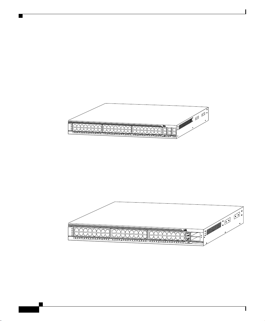
The Catalyst 4900 series switches (see Figure 1-1, Figure 1-2, and Figure 1-3) are
designed for high-performance, high-density edge switching applications. They
are fixed configuration switching solutions delivering 10/100/1000 connectivity
on all ports, supporting hot swappable, redundant power supplies in a compact
one rack-unit size for applications where space is limited.
Figure 1-1 Catalyst 4948 Switch
PS1
PS2
FAN
STATUS
1
1
6
17
32
33
C
a
ta
ly
s
t 4
9
4
8
C
O
N
M
G
T
48
45
46
47
48
113139
The Catalyst 4948 switch has a 96-Gbps, nonblocking, full-duplex switching
fabric, providing 72 million packets-per-second of switching capacity for
high-speed applications. The Catalyst
4948 chassis has 44
10BASE-T/100BASE-TX/1000BASE-T Ethernet ports and four ports that can be
either 1000BASE-X SFP ports or 10BASE-T/100BASE-TX/1000BASE-T
Ethernet ports.
Figure 1-2 Catalyst 4948-10GE Switch
P
S
1
P
S
2
F
A
N
S
T
A
T
U
S
1
1
6
1
7
3
2
3
3
C
ata
ly
st W
S
-C
4
9
4
8
1
0
G
E
X
2
-
1
X
2
-
C
48
2
O
N
M
G
T
The Catalyst 4948-10GE switch has a 136-Gbps, nonblocking, full-duplex
switching fabric, providing 102 million packets-per-second of switching capacity
for high-speed applications. The Catalyst
4948-10GE chassis has 48
10/100/1000BASE-T Ethernet ports and two 10-Gigabit Ethernet uplink ports.
130083
1-2
Catalyst 4900 Series Switch Installation Guide
78-18039-02
Page 25
Chapter 1 Product Overview
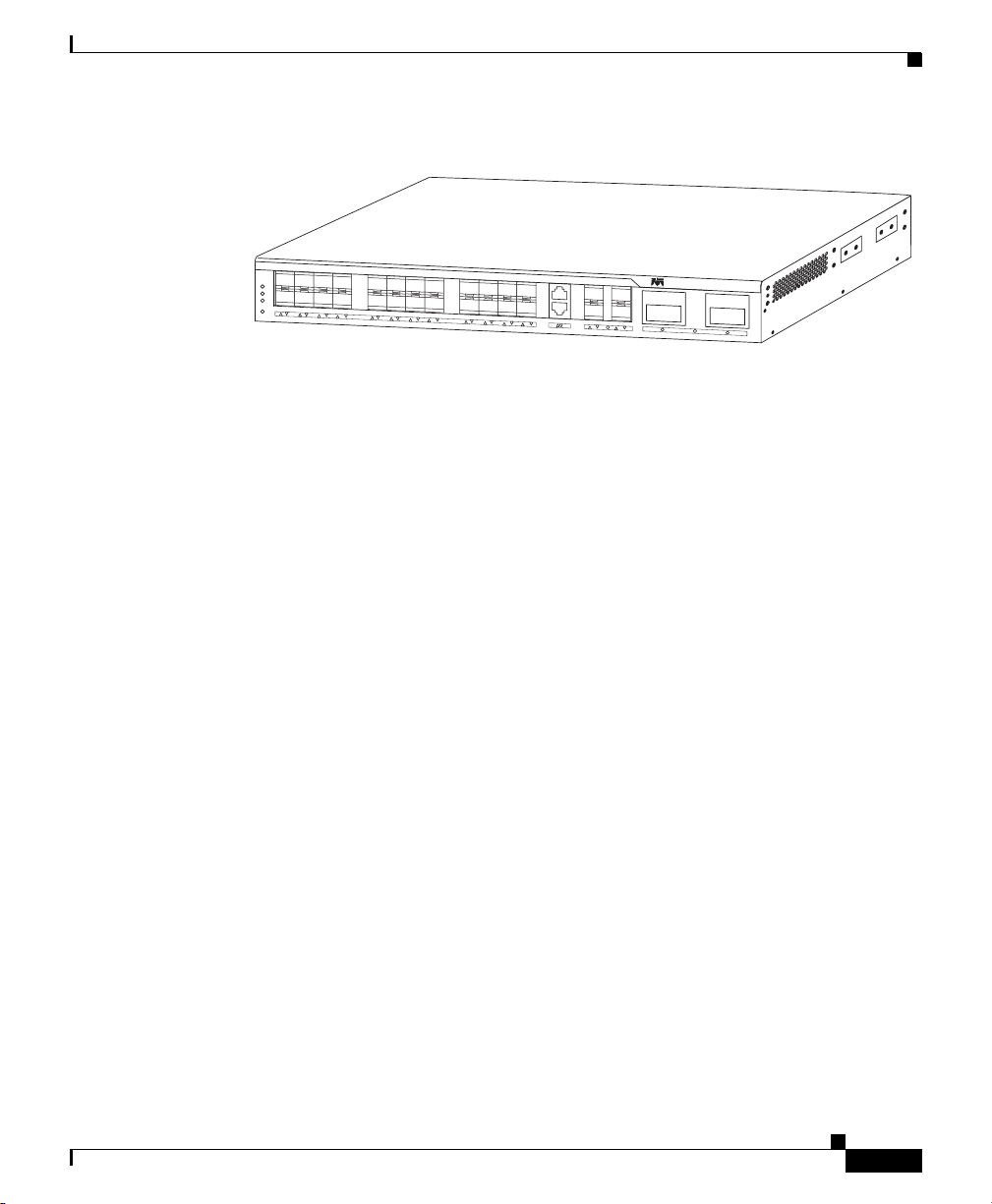
Figure 1-3 Catalyst 4928-10GE Switch
P
S
P
S
F
A
S
T
A
T
U
S
The Catalyst 4928-10GE switch has a 48-Gbps, nonblocking, full-duplex
switching fabric, providing 102 million packets-per-second of switching capacity
for high-speed applications. The Catalyst
SFP ports, and two X2 10-Gigabit Ethernet uplink ports.
All three switches have a removable automatic variable speed fan tray for low
noise operation at room temperature and removable and redundant 300
300
the
Catalyst 4948 Switch Software Features
C
a
t
a
ly
s
t
1
2
N
1
8
9
1
6
1
7
CON
MGMT
2
4
2
5
ENABLED
2
6
2
7
2
8
4928-10GE chassis has 28 1000BASEX
W DC power supply provides fault-tolerance protection for the switch. See
“Connecting AC Power to the Switch” section on page 3-9.
M
E
4
9
2
4
1
0
G
E
2
9
ENABLED
3
0
W AC or
271710
Catalyst 4948 Switch Software Features
The following is an overview of Catalyst 4948 features:
• Layer 2, Layer 3, and Layer 4 switching services
• Support for 32,768 MAC addresses for Layer 2 switching
• Support for 2,048 VLANs and 4,096 VLAN IDs
–
IEEE 802.1Q VLAN tagging on all ports
–
Q-in-Q for EFM
–
Cisco Inter Switch Link (ISL) tagging on all ports
• 16,000 multicast forwarding entries and 16,000 unicast forwarding entries
• 512 ingress policers and 512 egress policers
• 8,000 ingress Security ACEs (Access Control Entries) and 8,000 egress
Security ACEs
• Support for port aggregation using Port Aggregation Protocol (PAgP) for
Gigabit EtherChannel
Catalyst 4900 Series Switch Installation Guide
78-18039-02
1-3
Page 26

Catalyst 4948-10GE and Catalyst 4928-10GE Switch Software Features
• Catalyst 4500 series management software features include the following:
–
Command-line interface (CLI) and Simple Network Management
Protocol (SNMP) interfaces consistent with the Catalyst 4500 series
switches
–
Compatible development of new features with the Catalyst 4500 series
switches
–
Support for out-of-band management over serial lines through a terminal
attached to the console interface
–
Support for in-band management through any switch port through SNMP,
Telnet client, and Trivial File Transfer Protocol (TFTP)
–
Remote Monitoring (RMON) with RMON-1
–
Support for standard Layer 2 features: 802.1D Spanning Tree, Cisco
Discovery Protocol (CDP), VTP version 2 with pruning extensions, and
Cisco Group Management Protocol (CGMP) client
• Embedded management features include the following:
–
Full SNMP instrumentation including entity-Management Information
Base (MIB), all relevant standard MIBs, and all relevant Cisco MIBs
Chapter 1 Product Overview
–
Support for the first four RMON groups (Ethernet Statistics, Alarms,
Events, and History) on a per-port basis without the need for an optional
RMON processing module
–
Performance management information
–
Embedded CiscoView support
Catalyst 4948-10GE and Catalyst 4928-10GE Switch
Software Features
The following is an overview of Catalyst 4948-10GE features:
• Layer 2, Layer 3, and Layer 4 switching services
• Support for 55,000 MAC addresses for Layer 2 switching
• Support for 4,096 VLANs and 4,096 VLAN IDs
–
IEEE 802.1Q VLAN tagging on all ports
Catalyst 4900 Series Switch Installation Guide
1-4
78-18039-02
Page 27

Chapter 1 Product Overview
• 16,000 multicast forwarding entries and 16,000 unicast forwarding entries
• 1022 ingress policers and 1022 egress policers
• 32,000 ingress Security ACEs and 32,000 egress Security ACEs
• Support for port aggregation using Port Aggregation Protocol (PAgP) for
• Catalyst 4500 series management software features include the following:
Catalyst 4948-10GE and Catalyst 4928-10GE Switch Software Features
–
Q-in-Q for EFM
–
Cisco Inter Switch Link (ISL) tagging on all ports
Gigabit EtherChannel
–
Command-line interface (CLI) and Simple Network Management
Protocol (SNMP) interfaces consistent with the Catalyst 4500 series
switches
–
Compatible development of new features with the Catalyst 4500 series
switches
–
Support for out-of-band management over serial lines through a terminal
attached to the console interface
–
Support for in-band management through any switch port through SNMP,
Telnet client, and Trivial File Transfer Protocol (TFTP)
78-18039-02
–
Remote Monitoring (RMON) with RMON-1
–
Support for standard Layer 2 features: 802.1D Spanning Tree, Cisco
Discovery Protocol (CDP), VTP version 2 with pruning extensions, and
Cisco Group Management Protocol (CGMP) client
• Embedded management features include the following:
–
Full SNMP instrumentation including entity-Management Information
Base (MIB), all relevant standard MIBs, and all relevant Cisco MIBs
–
Support for the first four RMON groups (Ethernet Statistics, Alarms,
Events, and History) on a per-port basis without the need for an optional
RMON processing module
–
Performance management information
–
Embedded CiscoView support
Catalyst 4900 Series Switch Installation Guide
1-5
Page 28

Hardware System Features
Hardware System Features
The Catalyst 4900 series switches are high-performance dedicated Ethernet
switches that fully integrate into the Catalyst family of switches using Catalyst
4500 series system software.
The following is an overview of the Catalyst 4900 series hardware features:
• (Catalyst 4948 and 4948-10GE) 48 10BASE-T/100BASE-TX/1000BASE-T
Ethernet ports using RJ-45 interfaces. The following standards are supported:
–
IEEE 802.3 10BASE-T
–
IEEE 802.3u 100BASE-TX
–
IEEE 802.3z 1000BASE-X
–
IEEE 802.3x Pause and/or Full Duplex
–
IEEE 802.1Q
–
IEEE 802.3ab 1000BASE-T
–
IEEE 802.3ae
Chapter 1 Product Overview
1-6
–
IEEE 802.1p
• (Catalyst 4948) Four 1000BASE-X Ethernet ports using SFP interfaces
(These ports share MAC addresses with the last four
10BASE-T/100BASE-TX/1000BASE-T Ethernet ports.)
• (Catalyst 4928-10GE) 28 1000BASE-X Ethernet ports using SFP interfaces
• (Catalyst 4948-10GE and Catalyst 4928-10GE) Two 10-Gigabit Ethernet
uplink ports using X2 interfaces
• Serial console management port using an RJ-45 interface
• A removable automatic variable speed fan tray for low noise (no more than
48
dB) operation at room temperature
• Redundant and removable 300 W AC or 300 W DC power supplies
• 256-MB SDRAM (fixed), 64-MB embedded Flash memory
• EtherChannel at 10/100/1000 Mbps (and 10 Gbps for the Catalyst 4948-10GE
and Catalyst 4928-10GE)
• Hardware-based access lists
• Storm control in hardware
Catalyst 4900 Series Switch Installation Guide
78-18039-02
Page 29

Chapter 1 Product Overview
Switch Components
This section describes the hardware components.
Traffic Ports on the Catalyst 4948
There are 48 10/100/1000BASE-T Ethernet ports using RJ-45 interfaces and four
1000BASE-X Ethernet ports using SFP interfaces. These SFP ports share MAC
addresses with the last four 10/100/1000BASE-T ports. The interface
configuration mode command media-type sfp | rj45 can be used to configure the
media type for these ports in the switch software and to determine whether the
SFP connector or the RJ-45 connector is used. The default is SFP.
Traffic Ports on the Catalyst 4948-10GE
There are 48 10/100/1000BASE-T Ethernet ports using RJ-45 interfaces and two
10-Gigabit Ethernet uplink ports using X2 interfaces.
Switch Components
Traffic Ports on the Catalyst 4928-10GE
There are 28 1000BASE-X Ethernet ports using SFP interfaces.
Console Port
A console serial port (RJ-45) provides for switch management using standard
console equipment. (See
Appendix A, “Specifications,” for the console and management ports.
The Management port on the front panel is only operational when the switch is in
rommon mode. When in use, it offers the same TCP/IP based management
services available using inband access (Telnet, SNMP, etc.). IP address
configuration using BOOTP is supported on the Management port; it also
supports image download to the switch.
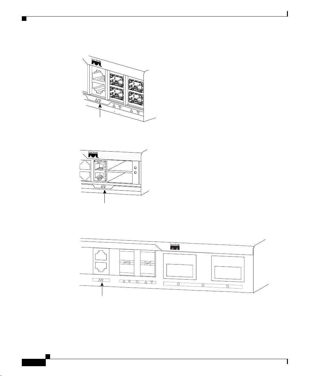
Figure 1-4 and Figure 1-5 show the location of the management and console ports
on the switches.
78-18039-02
Figure 1-4.) A connector pinout table is provided in
Catalyst 4900 Series Switch Installation Guide
1-7
Page 30
Switch Components
Chapter 1 Product Overview
Figure 1-4 (Catalyst 4948) Management Port LEDs Detailed View
Catalyst 4948
CO
N
MGT
45 46 47 48
MGT port LED
Figure 1-5 (Catalyst 4948-10GE) Management Port LEDs Detailed View
Catalyst WS-C4948 10GE
X2-1
X2-2
C
O
N
M
G
T
113140
1-8
MGT port LED
Figure 1-6 (Catalyst 4928-10GE) Management Port Detailed View
CON
MGMT
25
E
26
NABLED
Management
Port LED
Catalyst 4900 Series Switch Installation Guide
27
130084
28
C
at
alyst ME 4924 10GE
271711
29
E
NABLED
30
78-18039-02
Page 31

Chapter 1 Product Overview
Front Panel LEDs
The LEDs on the front panel of the switch (see Figure 1-4 and Figure 1-7) provide
status information as follows:
Figure 1-7 Detailed View of the STATUS LEDs
Switch Components
STA
PS1
PS2
FAN
TUS
1
113141
Power supply 1 LED
Power supply 2 LED
Fan LED
Port LEDs
STATUS LED
• STATUS LED indicates the operating state of the switch.
• PS1 LED indicates the internal power supply status.
• PS2 LED indicates the internal power supply status.
• FAN LED indicates the fan tray status.
• A link status LED is below the management port.
78-18039-02
Catalyst 4900 Series Switch Installation Guide
1-9
Page 32

Switch Components
Table 1-1 describes LED functions.
Ta b l e 1-1 LED Functions
LED Color or State Description
STATUS
Green
Red
Flashing
Yel low
Off
CON Green
At startup, the switch performs a series of
diagnostic tests:
All tests pass
A test other than an individual port test fails
System boot or diagnostic tests in progress
System is in rommon mode or a power supply
has failed
Switch is disabled
10/100 BASE-T console port is in link-up
state
Chapter 1 Product Overview
1-10
Off
MGT Green
Off
Port 1-48 Green
Yel low
Flashing yellow
Off
Catalyst 4900 Series Switch Installation Guide
10/100 BASE-T console port is in link-down
state or not connected
There are no blinking, red, or yellow states
for this port
10/100 BASE-T Management port is in
link-up state
10/100 BASE-T Management port is in
link-down state or not connected
There are no blinking, red, or yellow states
for this port
Port is operational
Port is disabled by user
Power-on self-test indicates faulty port
No signal detected or link configuration
failure
78-18039-02
Page 33

Chapter 1 Product Overview
Table 1-1 LED Functions (continued)
LED Color or State Description
FAN Off
PS1 and
PS2
1. If either LED is green and the other is OFF the power supply is probably not plugged in. If it is
Chassis Cooling
Switch Components
No power to the switch or fans (the tray may
Green
Red
Off
Green
Red
red, the supply is either plugged in and not switched on or it is faulty. It may be necessary to use
the CLI for further status information.
not be plugged in especially if one or more of
the power supplies status LED is green)
Fan tray operational
Fault detected
No power to the PS
Operational1
Fault detected or the on/off switch is set to
off while the power supply is plugged in
78-18039-02
Note For environmental specifications, see Chapter 2, “Site Planning.”
The hot-swappable system fan tray provides cooling air for the internal chassis
components. The fans exhaust air to the rear, and fresh air is drawn in from the
sides of the chassis.
Caution When the fan tray is removed, internal circuitry is exposed that should not be
touched by tools or fingers. The system should not be left operating without a fan
tray for longer than is necessary to replace a faulty fan tray with a new one.
Figure 1-8 shows the direction of airflow going in and out of the switch.
Catalyst 4900 Series Switch Installation Guide
1-11
Page 34

Switch Components
Figure 1-8 Airflow (Catalyst 4948-10GE shown)
S
T
There are four fans in the fan tray. If an individual fan fails, the other fans continue
to run. Sensors monitor the internal air temperatures. The number of fans in
operation and their speed varies according to the internal temperature for the
quietest operation possible. If the air temperature exceeds a desired threshold, the
environmental monitor displays warning messages.
Power Supplies
Chapter 1 Product Overview
P
S
1
P
S
2
F
A
N
A
T
U
S
1
1
6
1
7
3
2
3
3
C
a
ta
ly
s
t W
S
-C
49
4
8 1
0G
E
X
2
-
1
X
2
-
C
O
48
2
N
M
G
T
130085
1-12
Note For complete power specifications for the switch, see Appendix A,
“Specifications.”
The Catalyst 4900 series switches have two redundant internal 300 W AC or 300
W
DC power supplies.
The internal power supplies have individual power cords and status LEDs (PS1
and PS2 on the front panel). There are also LEDs on the power supplies that show
status for the input (Input OK) and output (Output OK) currents. A power cord is
used to connect the power supplies to the site power source. There is a power
switch on the AC power supplies; AC power is present when a power cord is
plugged into a power supply and the switch is set to the On position. DC power
supplies do not have an on/off switch and do not provide a cable for connection
to a DC power source.
Catalyst 4900 Series Switch Installation Guide
78-18039-02
Page 35

Chapter 1 Product Overview
Figure 1-9 On/Off Switch Locations
The switch will start with only one power supply plugged in, but redundant
failover and load sharing will not be available in this configuration. We
recommend that you always connect both power supplies to separate AC or DC
circuits for optimal power reliability.
For safety reasons, the AC power supply needs to be switched off and unplugged
before it is removed from a chassis or inserted into a chassis. DC supplies should
have power shut off from the source before they are removed.
If only one power supply will be used, you must use the blank faceplate supplied
to cover the empty power bay.
Switch Components
On/Off Switch
113143
Environmental Monitoring of the Power Supplies
Using the environmental monitoring and reporting functions, you can maintain
normal system operation by resolving adverse environmental conditions prior to
loss of operation.
Each power supply monitors its own temperature and output voltages. The switch
senses the operating condition of the power supply and reports status through
software.
Catalyst 4900 Series Switch Installation Guide
78-18039-02
1-13
Page 36

Switch Components
Power Management for the Switch
You can choose AC or DC power supplies for your switch. The Catalyst 4900
series switches support the following power supplies:
• 300 W AC
• 300 W DC
A redundant power supply can be identified and diagnosed by a running system
regardless of its input status. AC and DC supplies are interchangeable.
Power Management Modes
Catalyst 4900 series switches support the redundant power management mode. In
this mode, if both power supplies are operating normally, each provides from
20/80 to 45/55 percent of the total system power requirements at all times. If one
power supply fails, the other unit increases power to 100 percent of the total power
requirement.
Chapter 1 Product Overview
1-14
Catalyst 4900 Series Switch Installation Guide
78-18039-02
Page 37

CHAPTER
2
Site Planning
This chapter describes how to prepare your site for installation of the switch and
contains these sections:
• Site Environmental Requirements, page 2-1
• Site Power Requirements, page 2-2
• Grounding Requirements, page 2-6
• Safety Overview, page 2-7
• Site Planning Checklist, page 2-9
For detailed information about cabling requirements, see Chapter 4, “Transceiver
Modules.”
Note A site planning checklist is provided on page 3-5 to help ensure that you complete
all site planning activities before you install the switch.
Site Environmental Requirements
Planning a proper location for the switch and layout for your equipment rack or
wiring closet is essential for successful system operation. You should install the
switch in an enclosed, secure area, ensuring that only qualified personnel have
access to the switch and control of the environment. Equipment that is placed too
closely together or that is inadequately ventilated can cause system
overtemperature conditions. In addition, poor equipment placement can make
chassis panels inaccessible and difficult to maintain.
Catalyst 4900 Series Switch Installation Guide
78-18039-02
2-1
Page 38

Site Power Requirements
The switch operates as a standalone system mounted in a rack in a secure wiring
closet. It requires a dry, clean, well-ventilated, and air-conditioned environment.
To ensure normal operation, maintain ambient airflow. If the airflow is blocked or
restricted, or if the intake air is too warm, an overtemperature condition can occur.
The switch environmental monitor can then shut down the system to protect the
system components.
To ensure normal operation and avoid unnecessary maintenance, plan your site
configuration and prepare your site before installation. After installation, make
sure that the site maintains an ambient temperature of 0 to 40° C (32 to 104° F). It
is essential to keep the area around the chassis as free from dust and foreign
conductive material (such as metal flakes from nearby construction activity) as is
possible.
Multiple switches can be rack-mounted with little or no clearance above and
below the chassis. However, when mounting a switch in a rack with other
equipment, or when placing it on the floor near other equipment, ensure that the
exhaust from other equipment does not blow into the intake vents of the chassis.
Cooling air is drawn in through the sides and exhausted through the rear of the
chassis. Keep the sides and rear clear of obstructions, including dust and foreign
conductive material, and away from the exhaust ports of other equipment.
Appendix A, “Specifications,” lists the operating and nonoperating environmental
site requirements for the switches. To maintain normal operation and ensure high
system availability, maintain an ambient temperature and EMI-free and
continuous power at your site. The environmental ranges listed in
those within which the switch will continue to operate; however, a measurement
that approaches the minimum or maximum of a range indicates a potential
problem. You can maintain normal operation by anticipating and correcting
environmental anomalies before they exceed the maximum operating range.
Chapter 2 Site Planning
Appendix A are
Site Power Requirements
This section describes the installation site power requirements for the switch.
Verify your site power before you install the switch.
This section consists of the following sections:
• Pre-installation Requirements, page 2-3
• Warnings and Cautions, page 2-3
Catalyst 4900 Series Switch Installation Guide
2-2
78-18039-02
Page 39

Chapter 2 Site Planning
• EMI Recommendations, page 2-4
• Power Requirements and Heat Dissipation, page 2-4
Pre-installation Requirements
Follow these requirements when preparing your site for the switch installation:
• Connect each switch to separate wiring on a dedicated circuit; provide each
switch with its own branch circuit connection with sufficient overcurrent
protection and direct grounding to the branch circuit.
• To prevent a loss of input power, be sure the total maximum load on each AC
circuit is within the current ratings of the wiring and breakers.
Warnings and Cautions
Follow these precautions when preparing your site for the switch installation:
Site Power Requirements
78-18039-02
Caution The total maximum load on each AC-input power circuit must be within the rating
of the wiring and breaker. An overload of input power can result if this
requirement is not met.
Warning
Warning
Warning
Read the installation instructions before connecting the system to the power
source.
Installation of the equipment must comply with local and national electrical
codes.
Ultimate disposal of this product should be handled according to all national
laws and regulations.
Statement 1004
Statement 1074
Statement 1040
Catalyst 4900 Series Switch Installation Guide
2-3
Page 40

Site Power Requirements
EMI Recommendations
Follow these guidelines when setting up the site wiring. When planning the
location of the new system, consider electromagnetic interface (EMI), the
distance limitations for signaling, and connector compatibility.
When wires are run for any significant distance in an electromagnetic field, radio
frequency interference (RFI) can occur between the field and the signals on the
wires.
• Bad plant wiring can result in radio frequency interference.
• Strong EMI, especially when caused by lightning or radio transmitters, can
destroy the signal drivers and receivers in the switch and can create an
electrical hazard by conducting power surges through lines and into
equipment.
Note To predict and remedy strong EMI, you might need to consult RFI experts.
Chapter 2 Site Planning
Power Requirements and Heat Dissipation
The power requirements might be useful for planning the power distribution
system needed to support the switches. Heat dissipation is an important
consideration for sizing the air-conditioning requirements for an installation.
Refer to
switch.
Catalyst 4900 Series Switch Installation Guide
2-4
Appendix A, “Specifications,” for the power and heat ratings for a
78-18039-02
Page 41

Chapter 2 Site Planning
Site Power Requirements
You will also need to provide power to the switch with the appropriate AC power
cord for your location.
power supply.
Ta b l e 2-1 AC-Input Power Cord Options
Locale Part Number Length Plug Rating Plug Type
300 W AC Power Supply
North America CAB-US515-C15-US=
(was CAB-7KAC=)
Table 2-1 lists the power cords that are used with the AC
Appliance
Coupler
8.2 ft (2.5 m) 125 VAC, 15 A NEMA 5-15P
120352
120354
Australia,
New
Zealand
Europe (except
Italy)
CAB 13.2 ft
(4.0
m)
CAB 13.6 ft
(4.1
m)
CAB-AS3112-C15-AU=
8.2 ft (2.5 m) 250 VAC, 15 A SAA/3,
(was CAB-7ACA=)
CAB-CEE77-C15-EU=
8.2 ft (2.5 m) 250 VAC, 16 A CEE 7/7
(was CAB-7ACE=)
250 VAC, 16 A NEMA 6-20
non-locking
120355
250 VAC, 16 A NEMA L6-20
120361
AS/NZS 3112-1993
120356
120357
78-18039-02
Catalyst 4900 Series Switch Installation Guide
2-5
Page 42

Chapter 2 Site Planning
Grounding Requirements
Table 2-1 AC-Input Power Cord Options (continued)
Locale Part Number Length Plug Rating Plug Type
Italy CAB-C2316-C15-IT=
(was CAB-7ACI=)
8.2 ft (2.5 m) 250 VAC, 16 A 1/3/16 CEI 23-16
120358
United
Kingdom
Argentina CAB-IR2073-C15-AR=
CAB-BS1363-C15-UK=
(was CAB-7ACU=)
8.2 ft (2.5 m) 250 VAC, 13 A BS 89/13
8.2 ft (2.5 m) 250 VAC, 10 A IRAM 2073
(was CAB-7KACR=)
South Africa,
India
CAB-BS546-C15-SA=
(was CAB-7KACSA=)
8.2 ft (2.5 m) 250 VAC, 10 A BS 546
Grounding Requirements
Grounding is recommended on all AC or DC installations, using only approved
copper connectors. Attach the provided two hole ground lug to the chassis using
M4x 8mm bolts and then to the central office (CO) or other interior ground system
with number 6
chassis, and either one may be used. (See
AWG wire. The grounding connectors are on the right side of the
BS 1363/A
120359
120356
203795
Figure 2-1.)
2-6
Catalyst 4900 Series Switch Installation Guide
78-18039-02
Page 43

Chapter 2 Site Planning
Figure 2-1 Grounding Pad Locations (Catalyst 4849-10GE shown)
P
S
1
P
S
2
F
A
N
S
T
A
T
U
S
1
Safety Overview
This section provides safety information that you should read and understand to
ensure a safe switch installation.
Safety Overview
Grounding pads
C
a
ta
ly
st W
S
-C
4
9
48
1
0
G
E
X
2
-
1
X
2
-
1
6
1
7
3
2
3
3
C
48
2
O
N
M
G
T
130180
Ensuring Safety
Follow these guidelines to ensure your safety and protect the equipment. This list
is not inclusive of all potentially hazardous situations that you may be exposed to
as you install the switch, so be alert.
Warning
Warning
78-18039-02
Only trained and qualified personnel should be allowed to install, replace, or
service this equipment.
The plug-socket combination must be accessible at all times, because it serves
as the main disconnecting device.
Statement 1030
Statement 1019
Catalyst 4900 Series Switch Installation Guide
2-7
Page 44

Safety Overview
Chapter 2 Site Planning
Warning
Note To completely de-energize the system, unplug the power cord.
This equipment must be grounded. Never defeat the ground conductor or
operate the equipment in the absence of a suitably installed ground conductor.
Contact the appropriate electrical inspection authority or an electrician if you
are uncertain that suitable grounding is available.
• Always use caution when lifting heavy equipment. See the “Lifting the
Statement 1024
Chassis Safely” section on page 3-5 before lifting the switch.
• Always turn all power supplies off by unplugging all power cords before
installing or removing a chassis.
• Keep the chassis area clear and free of dust during and after installation.
• Keep tools and chassis components off of the floor and away from foot traffic.
• Avoid wearing jewelry (including rings and chains) or other items that could
get caught in the chassis. Avoid wearing any loose clothing, or securely fasten
items such as ties, scarves, or sleeves.
• Install the system in compliance with the following local and national
electrical codes:
–
United States—National Fire Protection Association (NFPA 70); United
States National Electrical Code
–
Canada—Canadian Electrical Code, Part I, CSA C22.1
–
Other countries—International Electrotechnical Commission (IEC)
60364, Part 1 through Part 7
Working Safely with Electricity
Follow these basic guidelines when working with any electrical equipment:
• Locate the emergency power-off switch for the room in which you are
working before beginning installation.
• Disconnect all power and external cables before installing or removing a
chassis.
Catalyst 4900 Series Switch Installation Guide
2-8
78-18039-02
Page 45

Chapter 2 Site Planning
• Do not work alone when potentially hazardous conditions exist.
• Never assume that power has been disconnected from a circuit; always check.
• Do not perform any action that creates a potential hazard to people or makes
the equipment unsafe.
• Examine your work area carefully for possible hazards such as moist floors,
ungrounded power extension cables, and missing safety grounds.
Preventing Electrostatic Discharge Damage
Electrostatic discharge (ESD) damage occurs when electronic cards or
components are improperly handled and can result in complete or intermittent
failures. Follow these guidelines to prevent ESD damage:
• Always use an ESD-preventive wrist or ankle strap, and ensure that it makes
maximum contact with the skin.
• When coming into contact with any internal components, always use a wrist
strap connected to one of the following:
Site Planning Checklist
–
ESD wrist strap connector
–
Any unpainted grounded surface on the chassis or equipment rack
Caution Periodically check the resistance value of the antistatic strap. The measurement
should be between 1 and 10 megohms (Mohms).
• Handle cards by the edges only.
• Avoid contact between the modules and clothing. The wrist strap protects
only the card from ESD voltages on the body; ESD voltages on clothing can
still cause damage.
Site Planning Checklist
Table 2-2 lists the site planning activities that you should perform before you
install the switch. Completing each activity helps to ensure a successful switch
installation.
78-18039-02
Catalyst 4900 Series Switch Installation Guide
2-9
Page 46

Chapter 2 Site Planning
Site Planning Checklist
Ta b l e 2-2 Site Planning Checklist
Task No. Planning Activity Verified By Time Date
1 Space evaluation:
Space and layout
Floor covering
Shock and vibration
Lighting
Maintenance access
2 Environmental evaluation:
Ambient temperature
Humidity
Altitude
Atmospheric contamination
Airflow
3 Power evaluation:
Input power type
Receptacle proximity to the equipment
Dedicated (separate) circuits for redundant power
supplies
UPS for power failures
4 Grounding evaluation:
Circuit breaker size
5 Cable and interface equipment evaluation:
Cable type
Connector type
Cable distance limitations
Interface equipment (transceivers)
6 EMI evaluation:
2-10
Distance limitations for signaling
Site wiring
RFI levels
Catalyst 4900 Series Switch Installation Guide
78-18039-02
Page 47

CHAPTER
3
Installing the Switch
This chapter describes how to install the Catalyst 4900 series switch. For
first-time installations, perform the procedures in the following sections in the
order listed.
• Verifying the Contents, page 3-1
• Rack-Mounting the Switch, page 3-2
• Connecting AC Power to the Switch, page 3-9
• Connecting DC Power to the Switch, page 3-11
Note Before starting the installation procedures in this chapter, complete the site
planning checklist in
activities were completed.
Chapter 2, “Site Planning,” to verify that all planning
Verifying the Contents
Note Do not discard the shipping container when you unpack the switch. Flatten the
shipping cartons and store them. You will need the container if you need to move
or ship the switch in the future.
78-18039-02
Catalyst 4900 Series Switch Installation Guide
3-1
Page 48

Rack-Mounting the Switch
To verify the contents of the shipping container follow these steps:
Step 1 Compare the contents of the accessories kit to the packing slip. Verify that you
received all listed equipment, which should include the following:
• Switch hardware and software documentation, if ordered
• Optional equipment that you ordered, such as network interface cables,
transceivers, or special connectors
Step 2 To begin installation, proceed to the “Rack-Mounting the Switch” section on
page 3-2.
Rack-Mounting the Switch
A standard rack-mount kit is included for mounting the switch in a standard
19-inch (48.3
unobstructed outer posts, a minimum depth between the front and rear mounting
posts of 19.25
This kit is not suitable for racks with obstructions (such as a power strip) that
could impair access to the switch.
cm) equipment rack. A standard equipment rack has two
inches (48.9 cm), and a maximum depth of 32 inches (81.3 cm).
Chapter 3 Installing the Switch
3-2
Caution Before installing the chassis in a rack, read the “Site Environmental
Requirements” section on page 2-1 to familiarize yourself with the proper site and
environmental conditions. Failure to read and follow these guidelines could lead
to an unsuccessful installation and possible damage to the system and
components.
Caution This unit is meant to be rack-mounted, and is not intended to bear more than its
own weight. Do not stack more than two on a table top, the added weight may
damage the bottom chassis.
Catalyst 4900 Series Switch Installation Guide
78-18039-02
Page 49

Chapter 3 Installing the Switch
Rack-Mounting the Switch
Warning
To prevent bodily injury when mounting or servicing this unit in a rack, you
must take special precautions to ensure that the system remains stable. The
following guidelines are provided to ensure your safety:
• This unit should be mounted at the bottom of the rack if it is the only unit in the rack.
• When mounting this unit in a partially filled rack, load the rack from the bottom to the
top with the heaviest component at the bottom of the rack.
• If the rack is provided with stabilizing devices, install the stabilizers before mounting
or servicing the unit in the rack.
Rack-Mounting Guidelines
Before rack-mounting the switch, ensure the following:
• The equipment rack is the proper size.
–
The width of the rack, between the two front mounting strips or rails,
must be 17.75
–
The depth of the rack, between the front and rear mounting strips, must
be at least 19.25
–
The rack must have sufficient vertical clearance to insert the chassis. The
chassis height is 1.75 inches (4.45 cm).
Statement 1006
inches (45.09 cm).
inches (48.9 cm) but not more than 32 inches (81.3 cm).
78-18039-02
• The equipment rack is stable and in no danger of falling over.
–
Ensure that the shelf is constructed to support the weight and dimensions
of the chassis. For physical specifications, see
Appendix A,
“Specifications.”
–
We recommend that you bolt the rack to the floor.
–
Mount the unit at the bottom of the rack if it is the only unit in the rack.
–
Install heavier equipment in the lower half of the rack to maintain a low
center of gravity and prevent the rack from becoming top-heavy and
tipping over.
Catalyst 4900 Series Switch Installation Guide
3-3
Page 50

Rack-Mounting the Switch
• The equipment rack is properly ventilated.
Chapter 3 Installing the Switch
–
Install the stabilizers before mounting or servicing the switch in the rack
(if the rack is provided with stabilizing devices).
–
Install the chassis in an enclosed rack only if it has adequate ventilation
or an exhaust fan; use an open rack whenever possible.
–
Ensure that the ambient temperature of the rack environment does not
exceed a maximum temperature of 104° F (40° C). Note that if the switch
is installed in a closed or multiunit rack assembly, the ambient operating
temperature of the rack environment might be higher than the ambient
room temperature.
–
Note that a ventilation system in a closed rack that is too powerful might
also prevent cooling by creating negative pressure around the chassis and
redirecting the air away from the chassis intake vent. If necessary,
operate the chassis with the rack open.
–
To prevent airflow restriction, allow at least 3 inches (7.6 cm) of
clearance around the ventilation openings on the sides of the chassis.
–
Use baffles correctly to assist in cooling the chassis.
–
Note that equipment near the bottom of a rack may generate excessive
heat that is drawn upward and into the intake ports of equipment above,
leading to overtemperature conditions in the chassis at or near the top of
the rack.
3-4
–
Consider the equipment and cabling that is already installed in the rack.
Ensure that cables from other equipment will not obstruct the airflow
through the chassis or impair access to the power supplies or switching
modules. Route cables away from field-replaceable components to avoid
disconnecting cables unnecessarily for equipment maintenance or
upgrades.
–
Allow at least 3 to 4 feet (91.4 to 121.9 cm) of clearance behind the rack
for maintenance and removal of switch assemblies. If the rack is mobile,
you can push it back within 1 foot (30.45 cm) of a wall or cabinet for
normal operation and pull it out when necessary for maintenance.
Catalyst 4900 Series Switch Installation Guide
78-18039-02
Page 51

Chapter 3 Installing the Switch
Lifting the Chassis Safely
The chassis is not intended to be moved frequently. Before you install the switch,
ensure that your site is properly prepared so that you can avoid moving the chassis
later to accommodate power sources and network connections.
Whenever you lift a chassis or any heavy object, follow these guidelines:
• Ensure that your footing is solid, and balance the weight of the chassis
between your feet.
• Lift the chassis slowly; never move suddenly or twist your body as you lift.
• Keep your back straight and lift with your legs, not your back. If you must
bend down to lift the chassis, bend at the knees, not at the waist, to reduce the
strain on your lower back muscles. (See
• Always disconnect all external cables before lifting or moving the chassis.
Figure 3-1 Unsafe Lifting Practices
Rack-Mounting the Switch
Figure 3-1.)
Required Installation Tools
The following tools and equipment are required to install the chassis:
• Number 1, number 2 Phillips, and 3/16-inch flat-blade screwdriver
• Antistatic mat or antistatic foam
78-18039-02
H1369a
Catalyst 4900 Series Switch Installation Guide
3-5
Page 52

Rack-Mounting the Switch
• Your own ESD grounding strap or the disposable ESD strap included with the
system
The following tools and equipment are required to install the chassis in a rack:
• Rack-mount kit
• Tape measure and level
Rack-Mounting the Switch
Note The illustrations shown are of a Catalyst 4948-10GE switch. The process for the
Catalyst 4948 and Catalyst 4928-10GE is identical.
Follow these steps to install the switch in a rack.
Step 1 Prepare for installation:
a. Place the chassis on the floor or on a sturdy table as close as possible to the
rack. Leave enough clearance to allow you to move around the chassis.
Chapter 3 Installing the Switch
3-6
b. Use a tape measure to measure the depth of the rack. Measure from the
outside of the front mounting posts to the outside of the rear mounting strip.
The depth must be at least 19.25
32
inches (81.3 cm).
c. Measure the space between the inner edges of the left front and right front
mounting posts to ensure that it is 17.75
is 17.5
inches [44 cm] wide and must fit between the mounting posts.)
d. Open the rack-mount kit, and refer to Table 3-1 to verify that all parts are
included.
Ta b l e 3-1 Rack-Mount Kit Checklist
Quantity Part Description Received
2 L brackets
8 M4 x 8 mm Phillips flat-head screws
Catalyst 4900 Series Switch Installation Guide
inches (48.9 cm) but not greater than
inches (45.09 cm) wide. (The chassis
78-18039-02
Page 53

Chapter 3 Installing the Switch
Table 3-1 Rack-Mount Kit Checklist
Quantity Part Description Received
4 12-24 x 3/4-inch Phillips binder-head screws
4 10-32 x 3/4-inch Phillips binder-head screws
Note Figure 3-2 illustrates how to attach the front of the switch to the rack. You
Step 2 Note that the L brackets connect the chassis to the rack. You can mount the
L
brackets to the front or rear mounting holes of the chassis, depending on which
end is in the front of the rack.
Note Some equipment racks provide a power strip along the length of one of
Rack-Mounting the Switch
can also attach the rear of the switch to the rack, depending on the
configuration of your rack.
the rear posts. If the rack has this feature, consider the position of the strip
when planning fastener points. Before installing the L brackets on the
chassis, determine whether to install the chassis from the front or the rear
of the rack.
78-18039-02
Attach the left and right L brackets using the M4 Phillips flat-head screws
provided in the rack-mount kit. (See
Figure 3-2 Attaching the L Brackets to the Switch
P
S
1
P
S
2
F
A
N
S
T
A
T
U
S
1
Step 3 Install the chassis in the rack as:
a. Position the chassis in the rack as follows (see Figure 3-3):
1
6
1
7
Figure 3-2.)
C
a
ta
ly
s
t W
S
-C
4
9
4
8
1
0
G
E
X2-1
X2-2
C
O
3
2
3
3
Catalyst 4900 Series Switch Installation Guide
N
M
G
T
48
130086
3-7
Page 54

Rack-Mounting the Switch
b. Align the mounting holes in the L bracket with the mounting holes in the
c. Secure the chassis using four (two on each side) 12-24 x 3/4-inch screws
d. Use a tape measure and level to ensure that the chassis is installed straight and
Figure 3-3 Installing the Switch in the Rack
Chapter 3 Installing the Switch
–
If the chassis front panel is in the front of the rack, insert the rear of the
chassis between the mounting posts.
–
If the rear of the chassis is in the front of the rack, insert the front of the
chassis between the mounting posts.
equipment rack.
through the elongated holes in the L bracket and into the threaded holes in the
mounting post.
level.
3-8
P
S
1
P
S
2
F
A
N
S
T
A
T
U
S
1
1
6
1
7
3
2
3
3
C
a
t
a
l
y
s
t
W
S
-
C
4
9
4
8
1
0
G
E
X2-1
X2-2
C
O
N
M
G
T
48
Step 4 Attach the cable guide to the right or left side of the chassis mount.
Catalyst 4900 Series Switch Installation Guide
130087
78-18039-02
Page 55

Chapter 3 Installing the Switch
Figure 3-4 Installing the Cable Guide
Step 5 Do not connect the power cord at this time. Proceed to the “Connecting AC Power
to the Switch” section on page 3-9.
Connecting AC Power to the Switch
P
S
1
P
S
2
F
A
N
S
T
A
T
U
S
1
1
6
1
7
3
2
3
3
C
a
t
a
l
y
s
t
W
S
-
C
4
9
4
8
1
0
G
E
X
2
-
1
X
2
-2
C
O
N
M
G
T
48
130089
Connecting AC Power to the Switch
Follow these steps and warnings when connecting power to a Catalyst 4900 series
switch:
Step 1 Prior to connecting the power supply to a power source, ensure that all of the site
power and grounding requirements described in
been met and the chassis is properly grounded as described in the “Grounding
Requirements” section on page 2-6.
Warning
Step 2 Plug the power cords into the power supplies. (Figure 3-6 shows plug locations.)
78-18039-02
The plug-socket combination must be accessible at all times, because it serves
as the main disconnecting device.
Statement 1019
Catalyst 4900 Series Switch Installation Guide
Chapter 2, “Site Planning,” have
3-9
Page 56

Connecting AC Power to the Switch
Figure 3-5 AC Power Supply
On/off switch
AC power plug
Chapter 3 Installing the Switch
Handle
3-10
Status LEDs
Step 3 Connect the other end of the power cords to an AC-power input source. If both
120696
power supplies will be used, make sure they are on different circuits.
Step 4 Turn the power switches to the ON position.
Step 5 Verify power supply operation by looking at the front panel power supply LEDs:
• The PS1 or PS2 LED is green when the power supply and fans are functioning
normally.
• The PS1 or PS2 LED is red when the power supply is not functioning
normally. The on/off switch may be set to off while the power supply is
plugged in, or the power supply may be defective and not providing DC
power to the switch. There may also be a fan failure.
• The PS1 or PS2 LED is off when there is no power supply installed.
Catalyst 4900 Series Switch Installation Guide
78-18039-02
Page 57

Chapter 3 Installing the Switch
From the system console, enter the show power command to display the power
supply and system status. For more information on this command, see the
command reference publication for your software release.
If the LEDs or show power command indicate a power or other system problem,
see
Chapter 5, “Troubleshooting the Installation,” for troubleshooting
information.
Connecting DC Power to the Switch
Follow these steps and warnings when connecting DC power to the Catalyst 4900
series switch:
Connecting DC Power to the Switch
Warning
Warning
Warning
Warning
Before performing any of the following procedures, ensure that power is
removed from the DC circuit.
This unit is intended for installation in restricted access areas. A restricted
access area can be accessed only through the use of a special tool, lock and
key, or other means of security.
This product requires short-circuit (overcurrent) protection, to be provided as
part of the building installation. Install only in accordance with national and
local wiring regulations.
Hazardous voltage or energy may be present on DC power terminals. Always
replace cover when terminals are not in service. Be sure uninsulated
conductors are not accessible when cover is in place.
Statement 1003
Statement 1017
Statement 1045
Statement 1075
78-18039-02
Catalyst 4900 Series Switch Installation Guide
3-11
Page 58

Connecting DC Power to the Switch
Step 1 Prior to connecting the power supply to a power source, ensure that all of the site
power and grounding requirements described in
been met and the chassis is properly grounded as described in the “Grounding
Requirements” section on page 2-6.
Step 2 Remove the safety cover from the power terminal.
Step 3 Connect the power supply ground terminal to earth ground.
Figure 3-6 DC Power Supply
DC input
terminals
Chapter 3 Installing the Switch
Chapter 2, “Site Planning,” have
3-12
Handle
Status LEDs
Step 4 Connect the positive and negative power cables into the power supplies using a
120697
number 2 Phillips screwdriver.
Note The DC power cables may use AWG #10 to AWG #12 wire.
Catalyst 4900 Series Switch Installation Guide
78-18039-02
Page 59

Chapter 3 Installing the Switch
Step 5 Replace the safety cover over the power terminals.
Step 6 Connect the other end of the power cables to an DC-power input source. If both
power supplies will be used, make sure they are on different circuits.
Step 7 Turn on the power from the power source. The DC supply does not have an on/off
switch.
Step 8 Verify power supply operation by looking at the front panel power supply LEDs:
• The PS1 or PS2 LED is green when the power supply is functioning normally.
• The PS1 or PS2 LED is red when the power supply is not functioning
• The PS1 or PS2 LED is off when the power supply is not connected to a power
From the system console, enter the show power command to display the power
supply and system status. For more information on this command, see the
command reference publication for your software release.
If the LEDs or show power command indicate a power or other system problem,
see
Chapter 5, “Troubleshooting the Installation,” for troubleshooting
information.
Connecting DC Power to the Switch
normally.
source.
78-18039-02
Catalyst 4900 Series Switch Installation Guide
3-13
Page 60

Connecting DC Power to the Switch
Chapter 3 Installing the Switch
3-14
Catalyst 4900 Series Switch Installation Guide
78-18039-02
Page 61

Transceiver Modules
This chapter tells you where to find instructions for installing SFP modules and
X2 modules, which are laser optical transceivers used for Ethernet connections.
Where needed, notes applying specifically to these switches are provided.
SFP Modules
To install SFP Modules, refer to the Cisco Small Form-Factor Pluggable Modules
Installation Note at the following location:
http://www.cisco.com/en/US/products/hw/modules/ps5455/prod_installation_gu
ide09186a00803aa0da.html
To get the latest information on SFP compatibility, refer to the relevant documents
at the following location:
http://www.cisco.com/en/US/products/hw/modules/ps5455/products_device_sup
port_tables_list.html
CHAPTER
4
SFP Modules and Alternative Wiring
The Catalyst 4948 switches have four ports that can be configured with any
combination of SFP modules with LC connectors, as shown in
interface configuration mode command media-type sfp|rj45 can be used to
configure the media type for these ports in the switch software and determines
whether the SFP or the RJ-45 connector is used. The default is SFP.
Catalyst 4900 Series Switch Installation Guide
78-18039-02
Figure 4-2. The
4-1
Page 62

X2 Modules
Note You must insert the SFP with the latching mechanism reversed on SFP port 46 and
port 48.
Figure 4-1 Connecting LC Connectors to the SFP Module (Catalyst 4948)
X2 Modules
CON
Catalyst 4948
AUX
45 46 47 48
Chapter 4 Transceiver Modules
113146
4-2
You must connect the cables and install the X2 modules as shown in Figure 4-2
and Figure 4-3. More general installation information is in the 10-Gigabit
Ethernet X2 Transceiver Installation Note at the following location:
http://www.cisco.com/en/US/products/hw/modules/ps5455/prod_installation_gu
ide09186a00803469ed.html
For compatibility information, refer to the 10-Gigabit Ethernet Transceiver
Modules Compatibility Matrix at the following location:
http://www.cisco.com/en/US/products/hw/modules/ps5455/products_device_sup
port_table09186a00803857e7.html
Catalyst 4900 Series Switch Installation Guide
78-18039-02
Page 63

Chapter 4 Transceiver Modules
Figure 4-2 Connecting SC Connectors to the X2 Module
If a module designed for operation on an SMF cable is directly coupled to an
MMF cable, an effect known as Differential Mode Delay (DMD) might occur. See
the Catalyst
X2 Modules
Catalyst WS-C4948 10GE
X
2
-1
X
2
-2
C
O
N
M
G
T
130088
4500 Series Module Installation Guide for more information.
78-18039-02
Catalyst 4900 Series Switch Installation Guide
4-3
Page 64

X2 Modules
Chapter 4 Transceiver Modules
Figure 4-3 Installing the 10-Gigabit Ethernet X2 Module
Catalyst WS-C4948 10GE
CON
L
MGT
CON
X1
I
N
K
X2
Catalyst WS-C4948 10GE
MGT
X1
X2
130091
4-4
Caution If you attempt to insert the bottom X2 module with the cooling fins pointing up,
you will probably permanently damage the connector. For either the top or bottom
connector, forcing a module could potentially damage both the module and the
switch.
Catalyst 4900 Series Switch Installation Guide
78-18039-02
Page 65

Chapter 4 Transceiver Modules
Tip For complete information on inspecting and cleaning fiber-optic connections,
refer to the white-paper document at this URL:
http://www.cisco.com/en/US/tech/tk482/tk876/technologies_white_paper09186a
0080254eba.shtml
Module Maintenance Guidelines
To properly maintain modules, follow these guidelines:
• To prevent ESD damage, follow normal handling procedures.
• When the module is stored or when a fiber-optic cable is not plugged in,
always keep plugs in the optical bores.
• The most common source of contaminants in the optical bores is debris
picked up on the ferrules of the optical connectors. Use an alcohol swab or
Kim-Wipe to clean the ferrules of the optical connector.
Cleaning the Fiber-Optic Connectors
Warning
Invisible laser radiation may be emitted from disconnected fibers or
connectors. Do not stare into beams or view directly with optical instruments.
Statement 1051
Cleaning the Fiber-Optic Connectors
In a fiber-optic system, light is transmitted through an extremely small fiber core,
often 62.5 microns or less in diameter. Because dust particles range from a tenth
of a micron to several microns in diameter, dust and any contamination at the end
of the fiber core can degrade the performance of the connector interface where the
two cores meet. Therefore, the connector must be precisely aligned, and the
connector interface must be absolutely free of trapped foreign material.
Catalyst 4900 Series Switch Installation Guide
78-18039-02
4-5
Page 66

Cleaning the Fiber-Optic Connectors
Connector loss, or insertion loss, is a critical performance characteristic of a
fiber-optic connector. Return loss is also an important factor. Return loss specifies
the amount of reflected light; the lower the reflection, the better the connection.
The best physical contact connectors have return losses greater than –40 dB,
although –20 to –30 dB is more common.
The connection quality depends on the type of connector and the proper cleaning
and connection techniques. Dirty fiber connectors are a common source of light
loss. Keep the connectors clean at all times, and keep the dust covers installed
when the connectors are not in use.
Before installing any type of cable or connector, use a lint-free alcohol pad from
a cleaning kit to clean the ferrule, the protective white tube around the fiber, and
the end-face surface of the fiber.
As a general rule, whenever there is a significant, unexplained loss of light, clean
the connectors.
Caution Use extreme care when removing or installing connectors so that you do not
damage the connector housing or scratch the end-face surface of the fiber. Always
install protective covers on unused or disconnected components to prevent
contamination. Always clean fiber connectors before installing them.
Chapter 4 Transceiver Modules
4-6
To clean the optical connectors, use a CLETOP cassette cleaner (type A for SC
connectors or type B for MT-RJ connectors) and follow the product directions. If
a CLETOP cassette cleaner is not available, follow these steps:
Step 1 Use a lint-free tissue soaked in 99 percent pure isopropyl alcohol to gently wipe
the faceplate. Wait five seconds for the surfaces to dry, and repeat.
Step 2 Remove any residual dust from the faceplate with clean, dry, oil-free compressed
air.
Warning
Catalyst 4900 Series Switch Installation Guide
Invisible laser radiation may be emitted from disconnected fibers or
connectors. Do not stare into beams or view directly with optical instruments.
Statement 1051
78-18039-02
Page 67

Chapter 4 Transceiver Modules
Step 3 Use a magnifying glass or inspection microscope to inspect the ferrule at an angle.
Do not look directly into the aperture. Repeat the process if any contamination is
detected.
Additional Guidelines
The connectors used inside the system have been cleaned by the manufacturer and
connected to the adapters in the proper manner. The operation of the system
should be error free if the customer provides clean connectors on the application
side, follows the previous directions, and follows these guidelines:
• Clean the connectors using either a CLETOP cassette cleaner (Type A for SC
connectors and Type B for MT-RJ connectors) or lens tissues before
connecting to the adapters. Use pure alcohol to remove contamination.
• Do not clean the inside of the connector adapters.
• Do not use force or quick movements when connecting the fiber-optic
connectors in the adapters.
Cleaning the Fiber-Optic Connectors
78-18039-02
• Cover the connectors and adapters to keep the inside of the adapters or the
surface of the connectors from getting dirty when you are not using the
connectors or while you are cleaning the chassis.
Catalyst 4900 Series Switch Installation Guide
4-7
Page 68

Cleaning the Fiber-Optic Connectors
Chapter 4 Transceiver Modules
4-8
Catalyst 4900 Series Switch Installation Guide
78-18039-02
Page 69

CHAPTER
5
Troubleshooting the Installation
This chapter describes how to troubleshoot the switch hardware installation and
contains these sections:
• Getting Started, page 5-2
• Problem Solving to the System Component Level, page 5-2
• Identifying Startup Problems, page 5-3
• Troubleshooting the Power Supply, page 5-5
• Contacting Customer Service, page 5-6
If your system has problems starting up, use the information in this chapter to help
isolate the cause. Problems with the initial startup are often caused by poor or
improper connections. Although temperature conditions above the maximum
acceptable level rarely occur at initial startup, environmental monitoring
functions are included because they also monitor DC-line voltages.
78-18039-02
Note For configuration questions or problems, refer to the software configuration guide
or the command reference publication.
Catalyst 4900 Series Switch Installation Guide
5-1
Page 70

Chapter 5 Troubleshooting the Installation
Getting Started
Getting Started
When the initial system boot is complete, verify the following:
• Power supplies are supplying power to the system.
• The system fan assembly is operating.
• System software boots successfully.
If all of these conditions are met and the hardware installation is complete, refer
to the Software Configuration Guide and the Command Reference publications to
troubleshoot the software. However, if any of these conditions are not met, use the
procedures in this chapter to isolate and, if possible, resolve the problem.
Problem Solving to the System Component Level
The key to success when troubleshooting the system is to isolate the problem to a
specific system component. The first step is to compare what the system is doing
to what it should be doing. Because a startup problem can usually be attributed to
a single component, it is more efficient to isolate the problem to a subsystem
rather than troubleshoot each separate component in the system.
5-2
The switch consists of the following subsystems:
• Power supply—Includes the power supply and power supply cooling. (See
the
“Troubleshooting the Power Supply” section on page 5-5.)
• Fan assembly system—The chassis fan assembly should operate whenever
system power is on. Usually, it continues to operate even when the
environmental monitor shuts down the system because of an overtemperature
or overvoltage condition. (It will shut down for a power supply shutdown.)
You should be able to hear the fan assembly to determine whether or not it is
operating. If the FAN LED is orange and you determine that the fan assembly
is not operating, you should immediately contact a customer service
representative. There are no installation adjustments that you can make if the
fan assembly does not function properly at the initial startup.
Catalyst 4900 Series Switch Installation Guide
78-18039-02
Page 71

Chapter 5 Troubleshooting the Installation
Identifying Startup Problems
When you connect the power cords to the switch, follow these steps:
Step 1 Flip the power switches to the on position (AC powered systems only).
Step 2 Verify that power is available to the power supplied from the site AC or DC
source. Flip breakers and fuses if necessary.
Step 3 Listen for the system fan assembly. If you do not immediately hear the system fan
assembly begin to operate, see
page 5-5.
Step 4 If you determine that the power supplies are functioning normally and that the fan
assembly is faulty, contact a customer service representative. If the system fan
assembly does not function properly at initial startup, there are no installation
adjustments that you can make.
“Troubleshooting the Power Supply” section on
Identifying Startup Problems
LED Readings
Step 1 Compare the LED states to those in Table 5-1.
78-18039-02
LEDs indicate all system states in the startup sequence. By checking the LEDs,
you can determine when and where the system failed in the startup sequence. To
check the LEDs, follow these steps:
Catalyst 4900 Series Switch Installation Guide
5-3
Page 72

Identifying Startup Problems
Ta b l e 5-1 Power Supply LED Meanings
LED and Color Meaning
INPUT OK (AC)
Chapter 5 Troubleshooting the Installation
This LED should turn green immediately when power is
applied to the supply and the power switch is set to ON.
Green
Red
Off
INPUT OK (DC)
Green
Red
Off
OUTPUT OK
Green
Red
AC input voltage is greater than 82 +/-3V.
In a dual power supply configuration (alternate unit
powered) the AC input is less than 73 +/-3V, or the power
supply is turned off.
AC input voltage is less than 73 +/-3V, or the power supply
is turned off.
This LED should turn green immediately when power is
applied to the supply.
DC input voltage is greater than -38.25 +/-2.25V.
In a dual power supply configuration (alternate unit
powered) the DC input is less than 33 +/-3V, or the power
supply is turned off.
In a single supply configuration, the LED shall be off to
signal that DC input is less than 33 +/-3V, or the power
supply is turned off.
DC output voltages are within the normal operating range.
Output voltage between the minimum and maximum limits
will not create an output fail alarm. Output voltages below
the minimum or above the maximum will create an output
fail alarm and cause the LED to illuminate red.
5-4
Step 2 Verify that the LEDs on the front panel are lit:
• The STATUS LED flashes yellow during diagnostic boot tests. It is green
when the switch is operational (online). If the system software is unable to
start up, this LED stays orange.
Catalyst 4900 Series Switch Installation Guide
78-18039-02
Page 73

Chapter 5 Troubleshooting the Installation
• The port LEDs (1-48) are green when the module is operational (online). If
no signal is detected, the LINK LED is off. The port LED remains yellow if
the port is disabled. The port LED flashes yellow if the port tested faulty at
startup.
Step 3 If a STATUS LED is red, contact a customer service representative for
instructions.
Step 4 If the boot information and system banner are not displayed, verify that the
terminal is set correctly and that it is connected properly to the console port.
Troubleshooting the Power Supply
Follow these steps to help isolate a power subsystem problem:
Step 1 Verify that the power supply is plugged in and that the on/off switch is set to ON
(if the power supply is an AC supply).
Troubleshooting the Power Supply
78-18039-02
Step 2 Look at the power supply LED (PS1 or PS2). If the LED is off or if the LED is
red, unplug the power cord, and then plug the power cord in. Be sure the on/off
switch is OFF before removing the power cord from the power supply.
Step 3 If the LED remains off, there might be a problem with the AC or DC source or the
power cable.
Step 4 Connect the power cord to another power source if one is available.
Step 5 If the LED then lights, the problem is the first power source.
Step 6 If the LED fails to light after you connect the power supply to a new power source,
replace the power cord.
Step 7 If the LED still fails to light when the switch is connected to a different power
source with a new power cord, the power supply is probably faulty.
If you are unable to resolve the problem, contact a customer service representative
for instructions.
Catalyst 4900 Series Switch Installation Guide
5-5
Page 74

Contacting Customer Service
Contacting Customer Service
If you are unable to solve a startup problem after using the troubleshooting
suggestions in this chapter, contact a customer service representative for
assistance and further instructions. Before you call, have the following
information ready to help your service provider assist you as quickly as possible:
• Date you received the switch
• Chassis serial number (located on a label on the right of the rear of the
chassis, see
• Type of software and release number
• Maintenance agreement or warranty information
• Brief description of the problem
• Brief explanation of the steps you have already taken to isolate and resolve
the problem
Figure 5-1 Serial Number Location
Figure 5-1)
Chapter 5 Troubleshooting the Installation
5-6
120534, 781-00289-01 A0
SN: AAANNNNXXXX
Catalyst 4900 Series Switch Installation Guide
78-18039-02
Page 75

Specifications
This appendix provides cable and technical specifications for the Catalyst 4900
series switches.
Console Port
The console port is an RJ-45 receptacle. The Request to Send (RTS) signal tracks
the state of the Clear to Send (CTS) input.
Ta b l e A-1 Console Port Pinouts
Pin Signal Direction Description
1 RTS output request to send
2 DTR output data terminal ready
3 TXD output transmit data
4 GND — —
5 GND — —
6 RXD input receive data
7 DSR input data set ready
8 CTS input clear to send
APPENDIX
Table A-1 lists the console port pinouts.
A
78-18039-02
Catalyst 4900 Series Switch Installation Guide
A-1
Page 76

Management Port
Management Port
The 10/100BASE-T (Catalyst 4948) or 10/100/1000BASE-T
(Catalyst
Status LED.
Ta b l e A-2 10/100BASE-T Port Pinouts
Pin Signal Direction Description
1 RXDP input receive data
2 RXDN input receive data
3 TXDP output transmit data
4 unused — —
5 unused — —
6 TXDN output transmit data
7 unused — —
8 unused — —
4948-10GE) management port use an RJ-45 receptacle with a Link
Appendix A Specifications
Table A-2 lists the 10/100BASE-T port pinouts.
A-2
Table A-3 lists the 10/100/1000BASE-T port pinouts.
Ta b l e A-3 10/100/1000 BASE-T Port Pinouts
Pin Signal Description
1 TXRX0P Bidirectional data pair 0
2 TXRX0N Bidirectional data pair 0
3 TXRX1P Bidirectional data pair 1
4 TXRX2P Bidirectional data pair 2
5 TXRX2N Bidirectional data pair 2
6 TXRX1N Bidirectional data pair 1
7 TXRX3P Bidirectional data pair 3
8 TXRX3N Bidirectional data pair 3
Catalyst 4900 Series Switch Installation Guide
78-18039-02
Page 77

Appendix A Specifications
Catalyst 4900 Series Switch Specifications
Catalyst 4900 Series Switch Specifications
Table A-4 shows Catalyst 4900 series switch specifications.
Ta b l e A-4 Catalyst 4900 Series Switch Specifications
Item Specification
Environmental
Temperature,
ambient operating
ambient nonoperating and storage
Humidity (RH),
ambient (noncondensing) operating
nonoperating and storage
Altitude
operating and nonoperating
Switch heat dissipation 1023 BTU/hour (Catalyst 4928-10GE)
32°F (0°C) to 104°F (40°C)
–40 to 167°F (–40 to 75°C)
10% to 90%
5% to 95%
–60 to 2000 m
600 BTU/hour (Catalyst 4948)
723 BTU/hour (Catalyst 4948-10GE)
System power dissipation 150 W (Catalyst 4928-10GE)
200 W (Catalyst 4948)
211 W (Catalyst 4948-10GE)
Switching Components
Memory 256-MB SDRAM, 64-MB Flash, 256 bytes serial EEROM
(all fixed and not upgradeable)
Physical Characteristics
Dimensions (H x W x D) 1.75 x 17.5 x 16 in. (4.5 x 44.5 x 40.6 cm)
Weight 17.5 lb (7.9 kg) for a system with two power supplies,
2.0
lb (0.9 kg) per power supply
Airflow Sides in, rear out
AC Power
Minimum input 85 VAC
Catalyst 4900 Series Switch Installation Guide
78-18039-02
A-3
Page 78

Appendix A Specifications
Catalyst 4900 Series Switch Specifications
Table A-4 Catalyst 4900 Series Switch Specifications (continued)
Item Specification
Power supply output 300 W
AC-input 4 A maximum @ 100 VA C
2 A maximum @ 240 VA C
AC frequency 50 to 60 Hz
Output current 25 A max
Peak current 4 A max @ 100 VAC
2 A max @ 240 VAC
Inrush value 20 A for one cycle of AC
Output voltage 12 V
Input KVA rating 0.375 KVA
DC Power
Minimum input –40.5 VDC
Power supply output 300 W
DC-input 8 A @ –48 to –60 VDC
Output current 25 A max
Peak current 8 A @ –48 to –60 VDC
Inrush value Cold turn on (PSU off for > 1 hour) – 45 A
Hot turn on (PSU on for > 1 hour) – 90 A
Output voltage 12 V
Input KVA rating 0.4 KVA
Catalyst 4900 Series Switch Installation Guide
A-4
78-18039-02
Page 79

APPENDIX
B
Initial Configuration for the Switch
This chapter provides a quick step-by-step initial setup procedure for a switch.
These steps describe how to do a simple installation:
1. Connecting to the Switch, page B-2
2. Starting the Terminal-Emulation Software, page B-3
3. Connecting to a Power Source, page B-3
4. Entering the Initial Configuration Information, page B-4
Note If you are using a DC power supply, see the “Connecting DC Power to the Switch”
section on page 3-11 for more information about setting up your switch with a DC
power supply.
Note You need to provide the Category 5 straight-through cables to connect the switch
ports to other Ethernet devices.
78-18039-02
Catalyst 4900 Series Switch Installation Guide
B-1
Page 80

Connecting to the Switch
Connecting to the Switch
You must use the console port to perform the initial configuration. To connect the
switch console port to a PC, use the supplied RJ-45-to-DB-9 adapter cable.
Follow these steps to connect the PC or terminal to the switch:
Step 1 Using the supplied RJ-45-to-DB-9 adapter cable, insert the RJ-45 connector into
the console port that is located on the front of the switch, as shown in
Step 2 Attach the DB-9 female DTE of the adapter cable to a PC serial port, or attach an
appropriate adapter to the terminal.
Figure B-1 Connecting a Switch to a PC
1
Appendix B Initial Configuration for the Switch
Figure B-1.
PS1
PS2
FAN
STATUS
1
1
6
1
7
3
2
3
3
1 Switch
2 Laptop
3 RJ-45-to-DB-9 adapter cable
Catalyst 4900 Series Switch Installation Guide
B-2
C
a
ta
ly
s
t 4
9
4
8
C
O
N
M
G
T
48
4
5
4
6
4
7
4
8
3
2
181874
78-18039-02
Page 81

Appendix B Initial Configuration for the Switch
Starting the Terminal-Emulation Software
Starting the Terminal-Emulation Software
Before you power on the switch, start the terminal-emulation session so that you
can see the output display from the power-on self-test (POST).
The terminal-emulation software—frequently a PC application such as
Hyperterminal or ProcommPlus—makes communication between the switch and
your PC or terminal possible.
Step 1 Start the terminal-emulation program if you are using a PC or terminal.
Step 2 Start a terminal-emulation session.
Step 3 Configure the baud rate and character format of the PC or terminal to match these
console port default characteristics:
• 9600 baud
• 8 data bits
• 1 stop bit
• No parity
• None (flow control)
Connecting to a Power Source
Follow these steps to connect to a power source:
Step 1 If you are using an AC power supply, connect one end of the supplied AC power
cord to the power connector on the switch rear panel, and then connect the other
end of the power cable to a grounded AC outlet. (See
Step 2 If you are using a DC power supply, see the “Connecting DC Power to the Switch”
section on page 3-11 for instructions on how to install the DC power supply.
As the switch powers on, it begins the POST, a series of tests that runs
automatically to ensure that the switch functions properly.
Catalyst 4900 Series Switch Installation Guide
78-18039-02
Figure B-1.)
B-3
Page 82

Appendix B Initial Configuration for the Switch
Entering the Initial Configuration Information
POST lasts approximately 1 minute. After POST is complete, the system and
status LEDs remain green (see the
more information).
If the switch fails POST, the system LED turns amber.
Note POST failures are usually fatal. Call Cisco Systems if your switch does not pass
POST.
If you started the terminal-emulation program before you powered on your
switch, the PC or terminal displays the bootloader sequence. Press Enter to
display the setup program prompt.
“Front Panel LEDs” section on page 1-9 for
Entering the Initial Configuration Information
To set up the switch, you need to assign an IP address and other configuration
information necessary for the switch to communicate with the local routers and
the Internet. The minimal configuration provided here does not cover most of the
features, it simply allows you to preform other configuration tasks using a telnet
connection from your management network. To configure other features and
interfaces, please refer to the Catalyst 4500 Series Switch Software Configuration
Guide.
IP Settings
Catalyst 4900 Series Switch Installation Guide
B-4
Obtain this information from your network administrator:
• Switch IP address
• Subnet mask (IP netmask)
• Default gateway (router)
• Enable secret password
• Enable password
• Telnet password
78-18039-02
Page 83

Appendix B Initial Configuration for the Switch
Performing the Initial Configuration
Follow these steps to complete the initial configuration for the switch:
Step 1 At the terminal prompt, enter the enable command to enter privileged exec mode:
Switch> enable
Password:
Switch#
Step 2 Set the system time using the clock set command in privileged EXEC mode.
Switch# clock set
Step 3 Verify the change by entering the show clock command.
Switch# show clock
20:09:06.079 UTC Thu Apr 3 2006
Step 4 Enter the configure terminal command to enter global configuration mode.
Switch# configure terminal
Enter configuration commands, one per line. End with CNTL/Z.
Switch (config)#
password
20:09:01 3 Apr 2006
Entering the Initial Configuration Information
78-18039-02
Step 5 Configure a host name for the switch, and press Return.
Switch (config)# hostname
Switch1
Step 6 Configure the system prompt for the switch, and press Return. To remove the new
prompt and return the prompt to its default, use the no prompt command.
Switch (config)# prompt Switch1>
Step 7 Use the banner motd global configuration command to set location information
in the login banner. You can also set a system contact using this command.
Switch1(config)# banner motd c
170 West Tasman Drive, San Jose, CA
c
or
Switch1 (config)# banner motd c
Tech Support 408 123 4567
c
Step 8 Configure an enable secret password, and press Return.
170 West Tasman Drive, San Jose, CA;
Catalyst 4900 Series Switch Installation Guide
B-5
Page 84

Entering the Initial Configuration Information
The password can be from 1 to 25 alphanumeric characters, can start with a
number, is case sensitive, allows spaces, but ignores leading spaces. The secret
password is encrypted and the enable password is in plain text.
Switch1 (config)# enable secret
Step 9 Configure an enable password, and press Return.
Switch1 (config)# enable password
Step 10 Configure a virtual terminal (Telnet) password, and press Return.
The password can be from 1 to 25 alphanumeric characters, is case sensitive,
allows spaces, but ignores leading spaces.
Switch1 (config)# password
Switch1 (config)# line vty
Step 11 Configure the interface that connects to the management network. (The IP address
and subnet mask shown are for example only. Use an address appropriate for your
network.)
Switch1 (config)# ip routing
Switch1 (config)# interface gigabitethernet
Switch1 (config-if)# no switchport
Switch1 (config-if)# no shutdown
Switch1 (config-if)# ip address
Switch1 (config-if)# exit
Appendix B Initial Configuration for the Switch
SecretPassword
EnablePassword
terminal-password
0 15
24
10.4.120.106 255.0.0.0
B-6
Step 12 Exit from global configuration mode:
Switch (config)# exit
Switch #
Step 13 View the configuration you just created and confirm that it is what you want.
Switch1# show run
!
hostname Switch1
!
banner motd ^C
170 West Tasman Drive, San Jose, CA ^C
!
!--- Output suppressed.
Step 14 Verify the IP information by using the show ip interface brief and show ip route
commands.
Switch1# show ip interface brief
Catalyst 4900 Series Switch Installation Guide
78-18039-02
Page 85

Appendix B Initial Configuration for the Switch
Interface IP-Address OK? Method Status
Protocol
Vlan1 172.16.1.2 YES manual up
up
FastEthernet1 unassigned YES unset up
up
!--- Output suppressed.
Switch1# show ip route
Codes: C - connected, S - static, I - IGRP, R - RIP, M - mobile, B BGP
D - EIGRP, EX - EIGRP external, O - OSPF, IA - OSPF inter area
N1 - OSPF NSSA external type 1, N2 - OSPF NSSA external type 2
E1 - OSPF external type 1, E2 - OSPF external type 2, E - EGP
i - IS-IS, L1 - ISIS level-1, L2 - ISIS level-2, ia - ISIS
inter area
* - candidate default, U - per-user static route, o - ODR
P - periodic downloaded static route
Gateway of last resort is 172.16.1.1 to network 0.0.0.0
172.16.0.0/24 is subnetted, 1 subnets
C 172.16.1.0 is directly connected, Vlan1
S* 0.0.0.0/0 [1/0] via 172.16.1.1
Switch1#
Entering the Initial Configuration Information
78-18039-02
Step 15 Save the running configuration:
Switch1# copy system:running-config nvram:startup-config
You have now completed the initial configuration of the switch.
To use the CLI to perform additional configuration or management tasks, enter
commands at the Switch> prompt through the console port by using a terminal
program or through the network by using Telnet. For configuration information,
refer to the switch software configuration guide or the switch command reference.
Catalyst 4900 Series Switch Installation Guide
B-7
Page 86

Entering the Initial Configuration Information
Appendix B Initial Configuration for the Switch
B-8
Catalyst 4900 Series Switch Installation Guide
78-18039-02
Page 87

APPENDIX
C
Compliance Information and Translated Safety Warnings
Note Only trained and qualified service personnel (as defined in IEC 60950-1 and
AS/NZS 60950) should install, replace, or service the equipment. Install the
system in accordance with the U.S. National Electric Code if you are in the United
States.
Warning
IMPORTANT SAFETY INSTRUCTIONS
This warning symbol means danger. You are in a situation that could cause
bodily injury. Before you work on any equipment, be aware of the hazards
involved with electrical circuitry and be familiar with standard practices for
preventing accidents. Use the statement number provided at the end of each
warning to locate its translation in the translated safety warnings that
accompanied this device.
SAVE THESE INSTRUCTIONS
Statement 1071
78-18039-02
This document includes the following sections:
• Translated Safety Warnings, page C-2
• Regulatory Standards Compliance, page C-39
• European Directives, page C-42
Catalyst 4900 Series Switch Installation Guide
C-1
Page 88

Appendix C Compliance Information and Translated Safety Warnings
Translated Safety Warnings
• California Perchlorate Contamination Prevention Act (Title 22, California
Code of Regulations, Chapter 33), page C-46
• EMC Class A Notices and Warnings, page C-46
Translated Safety Warnings
This section repeats in multiple languages the warnings in this guide.
Statement 1003—DC Power Disconnection
Warning
Waarschuwing
Varoitus
Attention
Warnung
Avvertenza
Advarsel
Aviso
Before performing any of the following procedures, ensure that power is
removed from the DC
Voordat u een van de onderstaande procedures uitvoert, dient u te controleren
of de stroom naar het gelijkstroom circuit uitgeschakeld is.
Varmista, että tasavirtapiirissä ei ole virtaa ennen seuraavien toimenpiteiden
suorittamista.
Avant de pratiquer l'une quelconque des procédures ci-dessous, vérifier que
le circuit en courant continu n'est plus sous tension.
Vor Ausführung der folgenden Vorgänge ist sicherzustellen, daß die
Gleichstromschaltung keinen Strom erhält.
Prima di svolgere una qualsiasi delle procedure seguenti, verificare che il
circuito CC non sia
Før noen av disse prosedyrene utføres, kontroller at strømmen er frakoblet
likestrømkretsen.
Antes de executar um dos seguintes procedimentos, certifique-se que
desligou a fonte de alimentação de energia do circuito de corrente contínua.
circuit.
alimentato.
Statement 1003
C-2
Catalyst 4900 Series Switch Installation Guide
78-18039-02
Page 89

Appendix C Compliance Information and Translated Safety Warnings
Translated Safety Warnings
¡Advertencia!
Varning!
Aviso
Advarsel
Antes de proceder con los siguientes pasos, comprobar que la alimentación
del circuito de corriente continua (CC) esté cortada (OFF).
Innan du utför någon av följande procedurer måste du kontrollera att
strömförsörjningen till likströmskretsen är bruten.
Antes de executar qualquer um dos procedimentos a seguir, verifique se a
energia foi removida do circuito DC.
Før du udfører nogen af følgende procedurer, skal du sikre dig, at der ikke er
strøm til jævnstrømskredsløbet.
78-18039-02
Catalyst 4900 Series Switch Installation Guide
C-3
Page 90

Appendix C Compliance Information and Translated Safety Warnings
Translated Safety Warnings
Statement 1004—Installation Instructions
Warning
Waarschuwing
Varoitus
Attention
Warnung
Avvertenza
Advarsel
Aviso
¡Advertencia!
Read the installation instructions before connecting the system to the power
source.
Statement 1004
Raadpleeg de installatie-instructies voordat u het systeem op de voedingsbron
aansluit.
Lue asennusohjeet ennen järjestelmän yhdistämistä virtalähteeseen.
Avant de brancher le système sur la source d'alimentation, consulter les
directives d'installation.
Vor dem Anschließen des Systems an die Stromquelle die
Installationsanweisungen lesen.
Consultare le istruzioni di installazione prima di collegare il sistema
all'alimentatore.
Les installasjonsinstruksjonene før systemet kobles til strømkilden.
Leia as instruções de instalação antes de ligar o sistema à fonte de energia.
Lea las instrucciones de instalación antes de conectar el sistema a la red de
alimentación.
C-4
Varning!
Läs installationsanvisningarna innan du kopplar systemet till
strömförsörjningsenheten.
Catalyst 4900 Series Switch Installation Guide
78-18039-02
Page 91

Appendix C Compliance Information and Translated Safety Warnings
Translated Safety Warnings
78-18039-02
Catalyst 4900 Series Switch Installation Guide
C-5
Page 92

Appendix C Compliance Information and Translated Safety Warnings
Translated Safety Warnings
Statement 1006—Chassis Warning for Rack-Mounting and
Servicing
Warning
Waarschuwing
Varoitus
To prevent bodily injury when mounting or servicing this unit in a rack, you
must take special precautions to ensure that the system remains stable. The
following guidelines are provided to ensure your safety:
• This unit should be mounted at the bottom of the rack if it is the only unit in the rack.
• When mounting this unit in a partially filled rack, load the rack from the bottom to the
top with the heaviest component at the bottom of the rack.
• If the rack is provided with stabilizing devices, install the stabilizers before mounting
or servicing the unit in the rack.
Om lichamelijk letsel te voorkomen wanneer u dit toestel in een rek monteert
of het daar een servicebeurt geeft, moet u speciale voorzorgsmaatregelen
nemen om ervoor te zorgen dat het toestel stabiel blijft. De onderstaande
richtlijnen worden verstrekt om uw veiligheid te verzekeren:
• Dit toestel dient onderaan in het rek gemonteerd te worden als het toestel het enige
in het rek is.
• Wanneer u dit toestel in een gedeeltelijk gevuld rek monteert, dient u het rek van
onderen naar boven te laden met het zwaarste onderdeel onderaan in het rek.
• Als het rek voorzien is van stabiliseringshulpmiddelen, dient u de stabilisatoren te
monteren voordat u het toestel in het rek monteert of het daar een servicebeurt geeft.
Kun laite asetetaan telineeseen tai huolletaan sen ollessa telineessä, on
noudatettava erityisiä varotoimia järjestelmän vakavuuden säilyttämiseksi,
jotta vältytään loukkaantumiselta. Noudata seuraavia turvallisuusohjeita:
Statement 1006
C-6
• Jos telineessä ei ole muita laitteita, aseta laite telineen alaosaan.
• Jos laite asetetaan osaksi täytettyyn telineeseen, aloita kuormittaminen sen
alaosasta kaikkein raskaimmalla esineellä ja siirry sitten sen yläosaan.
• Jos telinettä varten on vakaimet, asenna ne ennen laitteen asettamista telineeseen
tai sen huoltamista siinä.
Catalyst 4900 Series Switch Installation Guide
78-18039-02
Page 93

Appendix C Compliance Information and Translated Safety Warnings
Translated Safety Warnings
Attention
Warnung
Pour éviter toute blessure corporelle pendant les opérations de montage ou de
réparation de cette unité en casier, il convient de prendre des précautions
spéciales afin de maintenir la stabilité du système. Les directives ci-dessous
sont destinées à assurer la protection du personnelþ:
• Si cette unité constitue la seule unité montée en casier, elle doit être placée dans le
bas.
• Si cette unité est montée dans un casier partiellement rempli, charger le casier de
bas en haut en plaçant l'élément le plus lourd dans le bas.
• Si le casier est équipé de dispositifs stabilisateurs, installer les stabilisateurs avant
de monter ou de réparer l'unité en casier.
Zur Vermeidung von Körperverletzung beim Anbringen oder Warten dieser
Einheit in einem Gestell müssen Sie besondere Vorkehrungen treffen, um
sicherzustellen, daß das System stabil bleibt. Die folgenden Richtlinien sollen
zur Gewährleistung Ihrer Sicherheit dienen:
• Wenn diese Einheit die einzige im Gestell ist, sollte sie unten im Gestell angebracht
werden.
• Bei Anbringung dieser Einheit in einem zum Teil gefüllten Gestell ist das Gestell von
unten nach oben zu laden, wobei das schwerste Bauteil unten im Gestell anzubringen
ist.
• Wird das Gestell mit Stabilisierungszubehör geliefert, sind zuerst die Stabilisatoren
zu installieren, bevor Sie die Einheit im Gestell anbringen oder sie warten.
Avvertenza
78-18039-02
Per evitare infortuni fisici durante il montaggio o la manutenzione di questa
unità in un supporto, occorre osservare speciali precauzioni per garantire che
il sistema rimanga stabile. Le seguenti direttive vengono fornite per garantire
la sicurezza personale:
• Questa unità deve venire montata sul fondo del supporto, se si tratta dell’unica unità
da montare nel supporto.
• Quando questa unità viene montata in un supporto parzialmente pieno, caricare il
supporto dal basso all’alto, con il componente più pesante sistemato sul fondo del
supporto.
• Se il supporto è dotato di dispositivi stabilizzanti, installare tali dispositivi prima di
montare o di procedere alla manutenzione dell’unità nel supporto.
Catalyst 4900 Series Switch Installation Guide
C-7
Page 94

Translated Safety Warnings
Appendix C Compliance Information and Translated Safety Warnings
Advarsel
Aviso
¡Advertencia!
Unngå fysiske skader under montering eller reparasjonsarbeid på denne
enheten når den befinner seg i et kabinett. Vær nøye med at systemet er stabilt.
Følgende retningslinjer er gitt for å verne om
• Denne enheten bør monteres nederst i kabinettet hvis dette er den eneste enheten i
kabinettet.
• Ved montering av denne enheten i et kabinett som er delvis fylt, skal kabinettet lastes
fra bunnen og opp med den tyngste komponenten nederst i kabinettet.
• Hvis kabinettet er utstyrt med stabiliseringsutstyr, skal stabilisatorene installeres før
montering eller utføring av reparasjonsarbeid på enheten i kabinettet.
sikkerheten:
Para se prevenir contra danos corporais ao montar ou reparar esta unidade
numa estante, deverá tomar precauções especiais para se certificar de que o
sistema possui um suporte estável. As seguintes directrizes ajudá-lo-ão a
efectuar o seu trabalho com segurança:
• Esta unidade deverá ser montada na parte inferior da estante, caso seja esta a única
unidade a ser montada.
• Ao montar esta unidade numa estante parcialmente ocupada, coloque os itens mais
pesados na parte inferior da estante, arrumando-os de baixo para cima.
• Se a estante possuir um dispositivo de estabilização, instale-o antes de montar ou
reparar a unidade.
Para evitar lesiones durante el montaje de este equipo sobre un bastidor, o
posteriormente durante su mantenimiento, se debe poner mucho cuidado en
que el sistema quede bien estable. Para garantizar su seguridad, proceda
según las siguientes instrucciones:
C-8
• Colocar el equipo en la parte inferior del bastidor, cuando sea la única unidad en el
mismo.
• Cuando este equipo se vaya a instalar en un bastidor parcialmente ocupado,
comenzar la instalación desde la parte inferior hacia la superior colocando el equipo
más pesado en la parte inferior.
• Si el bastidor dispone de dispositivos estabilizadores, instalar éstos antes de montar
o proceder al mantenimiento del equipo instalado en el bastidor.
Catalyst 4900 Series Switch Installation Guide
78-18039-02
Page 95

Appendix C Compliance Information and Translated Safety Warnings
Translated Safety Warnings
Varning!
Aviso
Advarsel
För att undvika kroppsskada när du installerar eller utför underhållsarbete på
denna enhet på en ställning måste du vidta särskilda försiktighetsåtgärder för
att försäkra dig om att systemet står stadigt. Följande riktlinjer ges för att
trygga din säkerhet:
• Om denna enhet är den enda enheten på ställningen skall den installeras längst ned
på ställningen.
• Om denna enhet installeras på en delvis fylld ställning skall ställningen fyllas
nedifrån och upp, med de tyngsta enheterna längst ned på ställningen.
• Om ställningen är försedd med stabiliseringsdon skall dessa monteras fast innan
enheten installeras eller underhålls på ställningen.
Para evitar lesões corporais ao montar ou dar manutenção a esta unidade em
um rack, é necessário tomar todas as precauções para garantir a estabilidade
do sistema. As seguintes orientações são fornecidas para garantir a sua
segurança:
• Se esta for a única unidade, ela deverá ser montada na parte inferior do rack.
• Ao montar esta unidade em um rack parcialmente preenchido, carregue-o de baixo
para cima com o componente mais pesado em sua parte inferior.
• Se o rack contiver dispositivos estabilizadores, instale-os antes de montar ou dar
manutenção à unidade existente.
For at forhindre legemesbeskadigelse ved montering eller service af denne
enhed i et rack, skal du sikre at systemet står stabilt. Følgende retningslinjer
er også for din sikkerheds skyld:
78-18039-02
• Enheden skal monteres i bunden af dit rack, hvis det er den eneste enhed i racket.
• Ved montering af denne enhed i et delvist fyldt rack, skal enhederne installeres fra
bunden og opad med den tungeste enhed nederst.
• Hvis racket leveres med stabiliseringsenheder, skal disse installeres for enheden
monteres eller serviceres i racket.
Catalyst 4900 Series Switch Installation Guide
C-9
Page 96

Translated Safety Warnings
Appendix C Compliance Information and Translated Safety Warnings
C-10
•
•
•
•
•
•
Catalyst 4900 Series Switch Installation Guide
78-18039-02
Page 97

Appendix C Compliance Information and Translated Safety Warnings
C
,
I
,
C
,
G
,
N
e
r
A
p
b
•
•
•
CVP, the Cisco logo, and the Cisco Square Bridge logo are trademarks of Cisco Systems, Inc.; Changing the Way We Work, Live, Play, and Learn is a service mark of Cisco Systems
nc.; and Access Registrar, Aironet, BPX, Catalyst, CCDA, CCDP, CCIE, CCIP, CCNA, CCNP, CCSP, Cisco, the Cisco Certified Internetwork Expet logo, Cisco IOS, Cisco Press
isco Systems, Cisco Systems Capital, the Cisco Systems logo, Cisco Unity, Enterprise/Solver, EtherChannel, EtherFast, EtherSwitch, Fast Step, Follow Me Browsing, FormShare
igaDrive, HomeLink, Internet Quotient, IOS, iPhone, IP/TV, iQ Expertise, the iQ logo, iQ Net Readiness Scorecard, iQuick Study, LightStream, Linksys, MeetingPlace, MGX
etworking Academy, Network Registrar, Packet, PIX, ProConnect, ScriptShare, SMARTnet, StackWise, The Fastest Way to Increase Your Internet Quotient, and TransPath ar
egistered trademarks of Cisco Systems, Inc. and/or its affiliates in the United States and certain other countries.
ll other trademarks mentioned in this document or Website are the property of their respective owners. The use of the word partner does not imply a partnership relationshi
etween Cisco and any other company. (0705R)
Translated Safety Warnings
Catalyst 4900 Series Switch Installation Guide
78-18039-02
C-11
Page 98

Translated Safety Warnings
Appendix C Compliance Information and Translated Safety Warnings
C-12
Catalyst 4900 Series Switch Installation Guide
78-18039-02
Page 99

Appendix C Compliance Information and Translated Safety Warnings
Translated Safety Warnings
78-18039-02
Catalyst 4900 Series Switch Installation Guide
C-13
Page 100

Translated Safety Warnings
Appendix C Compliance Information and Translated Safety Warnings
Statement 1008—Class 1 Laser Product
Warning
Waarschuwing
Catalyst 4900 Series Switch Installation Guide
C-14
Class 1 laser product.
Klasse-1 laser produkt.
Statement 1008
78-18039-02
 Loading...