

Page 1

Cisco Business Access Point Administration Guide, Version 10.0.1.0
First Published: 2020-04-28
Americas Headquarters
Cisco Systems, Inc.
170 West Tasman Drive
San Jose, CA 95134-1706
USA
http://www.cisco.com
Tel: 408 526-4000
800 553-NETS (6387)
Fax: 408 527-0883
Page 2

THE SPECIFICATIONS AND INFORMATION REGARDING THE PRODUCTS IN THIS MANUAL ARE SUBJECT TO CHANGE WITHOUT NOTICE. ALL STATEMENTS,
INFORMATION, AND RECOMMENDATIONS IN THIS MANUAL ARE BELIEVED TO BE ACCURATE BUT ARE PRESENTED WITHOUT WARRANTY OF ANY KIND,
EXPRESS OR IMPLIED. USERS MUST TAKE FULL RESPONSIBILITY FOR THEIR APPLICATION OF ANY PRODUCTS.
THE SOFTWARE LICENSE AND LIMITED WARRANTY FOR THE ACCOMPANYING PRODUCT ARE SET FORTH IN THE INFORMATION PACKET THAT SHIPPED WITH
THE PRODUCT AND ARE INCORPORATED HEREIN BY THIS REFERENCE. IF YOU ARE UNABLE TO LOCATE THE SOFTWARE LICENSE OR LIMITED WARRANTY,
CONTACT YOUR CISCO REPRESENTATIVE FOR A COPY.
The Cisco implementation of TCP header compression is an adaptation of a program developed by the University of California, Berkeley (UCB) as part of UCB's public domain version of
the UNIX operating system. All rights reserved. Copyright©1981, Regents of the University of California.
NOTWITHSTANDING ANY OTHER WARRANTY HEREIN, ALL DOCUMENT FILES AND SOFTWARE OF THESE SUPPLIERS ARE PROVIDED “AS IS" WITH ALL FAULTS.
CISCO AND THE ABOVE-NAMED SUPPLIERS DISCLAIM ALL WARRANTIES, EXPRESSED OR IMPLIED, INCLUDING, WITHOUT LIMITATION, THOSE OF
MERCHANTABILITY, FITNESS FOR A PARTICULAR PURPOSE AND NONINFRINGEMENT OR ARISING FROM A COURSE OF DEALING, USAGE, OR TRADE PRACTICE.
IN NO EVENT SHALL CISCO OR ITS SUPPLIERS BE LIABLE FOR ANY INDIRECT, SPECIAL, CONSEQUENTIAL, OR INCIDENTAL DAMAGES, INCLUDING, WITHOUT
LIMITATION, LOST PROFITS OR LOSS OR DAMAGE TO DATA ARISING OUT OF THE USE OR INABILITY TO USE THIS MANUAL, EVEN IF CISCO OR ITS SUPPLIERS
HAVE BEEN ADVISED OF THE POSSIBILITY OF SUCH DAMAGES.
Any Internet Protocol (IP) addresses and phone numbers used in this document are not intended to be actual addresses and phone numbers. Any examples, command display output, network
topology diagrams, and other figures included in the document are shown for illustrative purposes only. Any use of actual IP addresses or phone numbers in illustrative content is unintentional
and coincidental.
All printed copies and duplicate soft copies of this document are considered uncontrolled. See the current online version for the latest version.
Cisco has more than 200 offices worldwide. Addresses and phone numbers are listed on the Cisco website at www.cisco.com/go/offices.
Cisco and the Cisco logo are trademarks or registered trademarks of Cisco and/or its affiliates in the U.S. and other countries. To view a list of Cisco trademarks, go to this URL: www.cisco.com
go trademarks. Third-party trademarks mentioned are the property of their respective owners. The use of the word partner does not imply a partnership relationship between Cisco and any
other company. (1721R)
©
2020 Cisco Systems, Inc. All rights reserved.
Page 3

The Java logo is a trademark or registered trademark of Sun Microsystems, Inc. in the U.S. or other countries.
©
2020 Cisco Systems, Inc. All rights reserved.
Page 4

Page 5

CONTENTS
CHAPTER 1
CHAPTER 2
CHAPTER 3
Cisco Business Wireless Access Points Overview 1
About Cisco Business Wireless Access Points 1
Supported Cisco Access Points 1
Supported Software Images 2
Supported Browsers 2
Related Documents 2
Using Cisco Business Wireless Access Point GUI 5
Using the Cisco Business Wireless Access Point GUI 5
Getting Started 9
Prerequisite for Setting up and Accessing Cisco Business Wireless AP 9
AP Deployment Models 10
Launching the Setup Wizard 11
Using the Setup Wizard 12
Logging into the Cisco Business Wireless AP 14
CHAPTER 4
Adding New Subordinate APs 15
Adding Mesh Extenders 15
Monitoring 17
About the Cisco Business Wireless AP Monitoring Service 17
Customizing the Network Summary View 18
Customizing Access Points Table View 19
Viewing Access Point Details 20
Viewing Client Details 23
Viewing Guest Client Details 26
Cisco Business Access Point Administration Guide, Version 10.0.1.0
v
Page 6

Contents
Troubleshooting a Client 26
Performing a Client Ping Test 26
Performing a Connection Test 27
Generating an Event Log 27
Viewing Mesh Extender 28
Viewing Applications 28
Viewing Rogue Access Points 28
Configuring the Rogue AP States 29
Viewing Rogue Client Details 30
Viewing Interferer Details 30
Wireless Dashboard 31
Customizing the Access Point Performance View 32
Adding Widgets 33
CHAPTER 5
Removing Widgets 33
Customizing the Client Performance View 33
Adding a Widget 34
Removing a Widget 34
Wireless Settings 35
About WLANs and RLANs in CBW Access Point Network 35
Setting Up WLANs RLANs and WLAN Users 35
Viewing WLANs 36
Adding and Modifying a WLAN 37
Configuring General Details 37
Configuring WLAN Security 38
Configuring VLAN and Firewall 43
Configuring Traffic Shaping 43
Configuring Advanced Options 45
Configuring Scheduling 46
Enabling and Disabling WLANs RLANs 47
Configuring RLAN in AP 47
Editing and Deleting WLANs RLANs 48
Viewing and Managing WLAN Users 48
Blocking and Unblocking Clients 49
Cisco Business Access Point Administration Guide, Version 10.0.1.0
vi
Page 7

Social Login for Guest Users 50
Managing Associated Access Points 50
Global AP Configuration 51
Administering Access Points 52
Access Point Groups 54
Setting a Login Page for WLAN Guest Users 54
Setting the Default Login Page 55
Setting a Customized Login Page 56
About Cisco Mesh 57
Convert Non-Mesh to Mesh Deployment 57
Mesh Network Components 58
Changing Mesh Parameters 60
Backhaul Client Access 60
Contents
CHAPTER 6
Mesh Backhaul Radio Resource Management 61
Mesh Backhaul Slot 61
Modifying AP Port Configuration to Access/Trunk Mode 61
VLAN Transparent 62
Management 63
About Management Access Interface 63
Setting Up Management Access Interface 63
Limitation of Web Based Management Sessions 64
Managing User Priority Order 64
Managing Admin Accounts 65
Adding an Admin Account 65
Editing an Admin Account 66
Deleting an Admin Account 66
Managing Guest Users using the Lobby Admin account 67
Creating a Guest User Account 67
Managing TACACS+ and RADIUS Servers 68
Adding TACACS+ Servers 68
Configuring RADIUS Servers 68
Adding RADIUS Servers 70
Setting Date and Time 71
Cisco Business Access Point Administration Guide, Version 10.0.1.0
vii
Page 8

Contents
Using NTP Servers to Automatically Set the Date and Time 71
Adding and Editing NTP Servers 71
Refreshing NTP Server Status 72
Deleting and Disabling NTP Servers 72
Configuring Date and Time Manually 72
Updating the CBW AP Software 73
Updating the Software using HTTP 75
Updating the Software using TFTP 76
Updating the Software using SFTP 77
Updating the Software through Cisco.com 78
CHAPTER 7
CHAPTER 8
Services 81
About Multicast Domain Name System 81
Restrictions for Configuring Multicast DNS 83
Configuring Multicast DNS 83
Mapping mDNS Profile to WLAN 84
Configuring mDNS Policy 85
Cisco Umbrella Overview 86
Configuring Cisco Umbrella on Master AP 87
Adding Policy to Umbrella Profile 87
Applying Cisco Umbrella Profile to WLAN 88
Advanced 89
Managing SNMP 89
Configuring SNMP Access 89
SNMP Trap Receivers 90
Add an SNMPv3 User 90
viii
Delete SNMPv3 User 91
Setting Up System Message Logs 92
System Logs 92
Optimizing RF Parameters 93
Advanced RF Parameters 93
Optimized Roaming 93
Restrictions for Optimized Roaming 94
Cisco Business Access Point Administration Guide, Version 10.0.1.0
Page 9

Configuring Optimized Roaming 94
RF Profiles 95
RF Parameter Optimization Settings 96
Troubleshooting in Master AP 98
UI Indicator 98
Using Master AP Tools 98
Restarting the Master AP 98
Clearing the Master AP Configuration and Resetting 98
Export and Import Master AP Configuration 99
Saving the Master AP Configuration 99
Troubleshooting Files 100
Troubleshooting Tools 100
Uploading Files 101
Contents
APPENDIX A
APPENDIX B
Security Settings 101
Configuring Access Control Lists (ACL) 102
Applying the ACL to WLAN at Pre-Auth Level 104
Applying the ACL to WLAN at Post-Auth Level 104
Configuring AAA Override in WLAN 104
Appendix - Supporting Topics 107
LAN port functionality for different models 107
LED Color Indicators for Cisco Business Wireless APs 107
LED Display Settings 110
Master AP Failover and Election Process 110
Pre-downloading an Image to an Access Point 111
Creating a Guest Network 111
Resetting a Device to Factory Default 112
Deployment and Troubleshooting Guidelines 112
Appendix - Mounting and Grounding Access Points 115
About Mounting 115
Preparing the AP for Installation 115
Mounting CBW140AC/240AC 116
Mounting CBW145AC 121
Cisco Business Access Point Administration Guide, Version 10.0.1.0
ix
Page 10

Contents
Mounting CBW141AC 126
Mounting CBW142AC 127
Mounting CBW143AC 132
Grounding an Access Point 134
Securing an Access Point 135
APPENDIX C
Appendix - Glossary of Terms 137
Cisco Business Wireless - Glossary Of Terms 137
0-9 137
802.1Q-based VLAN 137
802.1X Supplicant 137
A 137
ACL 137
B 138
Band Steer 138
Bandwidth 138
Bandwidth Utilization 138
Blacklist 138
C 138
Captive Portal 138
Central web authentication (CWA) 138
Channel Isolation 138
Channel Width 138
Client QoS 139
Connection Speed 139
E 139
EAPol 139
Event Logging 139
F 139
Fast Roaming 139
H 139
HTTPS 139
I 140
IPv4 140
Cisco Business Access Point Administration Guide, Version 10.0.1.0
x
Page 11

IPv6 140
ISE 140
L 140
LLDP 140
Load Balancing 140
M 140
Max Data Rate 140
Multiple SSIDs 140
O 141
Operating Mode 141
P 141
PMKID 141
Q 141
Contents
QoS 141
R 141
RADIUS Server 141
Radio Domains 141
Rogue AP Detection 141
S 142
Scheduler 142
Signal Quality 142
Signal Strength 142
Spatial Streams 142
Spectrum Intelligence 142
SSID 142
SSID Broadcast 142
V 143
VLAN 143
W 143
WDS 143
Whitelist 143
WPA/WPA2 143
WPA2 Enterprise 143
Cisco Business Access Point Administration Guide, Version 10.0.1.0
xi
Page 12

Contents
APPENDIX D
Appendix - Cisco Online Support 145
Cisco Business Online Support 145
xii
Cisco Business Access Point Administration Guide, Version 10.0.1.0
Page 13

CHAPTER 1
Cisco Business Wireless Access Points Overview
This chapter contains the following sections:
• About Cisco Business Wireless Access Points, on page 1
• Supported Cisco Access Points, on page 1
• Supported Software Images, on page 2
• Supported Browsers, on page 2
• Related Documents, on page 2
About Cisco Business Wireless Access Points
The Cisco Business Wireless (CBW) network solution comprises of at least one 802.11ac Wave 2 Cisco
Business Series Access Point with an in-built software that manages other access points in the network.
An Access Point (AP) that controls all the Access Points in the network is termed as the Master AP and the
access points controlled by the Master AP is termed as the Subordinate AP in this guide.
The Master AP has two roles: It controls all the Subordinate APs that joins the network. It independently
serves wireless clients like other Subordinate APs.
You may refer this administration guide for details on both the Master APs and the Subordinate APs. It
provides instructions on getting started with an access point and also explains various options available to
monitor and manage the APs using the WebUI.
Supported Cisco Access Points
The following Cisco Business Series APs are supported in the Cisco Business Wireless (CBW) AP network:
Note
• APs listed under Master APs can also function as Subordinate APs.
• This Administration Guide can be referred for both Master APs and the Subordinate APs of all models
in this series.
Cisco Business Access Point Administration Guide, Version 10.0.1.0
1
Page 14

Supported Software Images
Table 1: Cisco APs supported in the CBW AP network
Cisco Business Wireless Access Points Overview
Subordinate APsMaster APs
Cisco Business 141AC Mesh ExtenderCisco Business 140AC Access Point
Cisco Business 142AC Mesh ExtenderCisco Business 240AC Access Point
Cisco Business 143AC Mesh ExtenderCisco Business 145AC Access Point
Note
may be used as Subordinate APs, the Mesh
Extenders (141, 142 & 143) cannot be used
as a Master AP.
Supported Software Images
You can download the CBW AP software for your AP model by navigating to
https://software.cisco.com/download/navigator.html
From the Software Download window, go to Wireless > Access Points. Based on your AP model, navigate
to Cisco Business 100 Series Access Points/Cisco Business 200 Series Access Points and select a model
from the list. You can view a list of currently available software with the latest version at the top. Choose the
required version of the firmware image and proceed with the download to update the software.
Supported Browsers
Cisco Business Wireless Access Points are administered through a web user interface. To use this interface,
your browser must be one of the following:
• Microsoft Internet Explorer 10 or above
Cisco Business 140AC Access PointWhile the Master APs (140, 145 & 240)
Cisco Business 240AC Access Point
Cisco Business 145AC Access Point
• Apple Safari version 7 or above
• Mozilla Firefox version 33 or above
• Google Chrome version 38 or above
You can also use the Cisco Business App on your mobile phone to monitor and administer the Access Points.
You will need one of the following Operating Systems:
• Android version 5.0 or above
• iOS version 8.0 or above
Related Documents
The documentation for Cisco Business Wireless Access Points is comprised of a number of separate guides.
These include the following:
Cisco Business Access Point Administration Guide, Version 10.0.1.0
2
Page 15

Cisco Business Wireless Access Points Overview
Related Documents
Administration Guide
Quick Start Guide
Release Notes
Open Source Documents
(OSD)
Cisco Regulatory Compliance
and Safety Information
(RCSI)
Translated End-User
Documents
This guide provides details on performing configuration for Cisco Business
Wireless Access Points (APs) and also provides advanced options to manage
and monitor APs in the Cisco Business Wireless AP network.
Note
This guide can be referred for both Master APs and the
Subordinate APs of all models in this CBW series.
This guide provides details on performing the initial setup and configuration
for Cisco Business Wireless Access Points (APs) using the most commonly
selected options. For an overview of the basic tasks, refer the Cisco Business
Wireless Quick Start Guide.
Summary of the features and caveats for Cisco Business Wireless Access
Points (APs).
This document contains the licenses and notices for open source software
used in this product.
This document provides domestic and international regulatory compliance
and safety information for the Cisco Business Wireless Access Points (APs).
The Translated Administration Guides for all APs supported by the Cisco
Business Wireless Access Points (APs) are available in the Cisco Business
Wireless Access Points (APs) product page on Cisco.com.
Cisco Business Access Point Administration Guide, Version 10.0.1.0
3
Page 16

Related Documents
Cisco Business Wireless Access Points Overview
Cisco Business Access Point Administration Guide, Version 10.0.1.0
4
Page 17
CHAPTER 2
Using Cisco Business Wireless Access Point GUI
This chapter contains the following sections:
• Using the Cisco Business Wireless Access Point GUI, on page 5
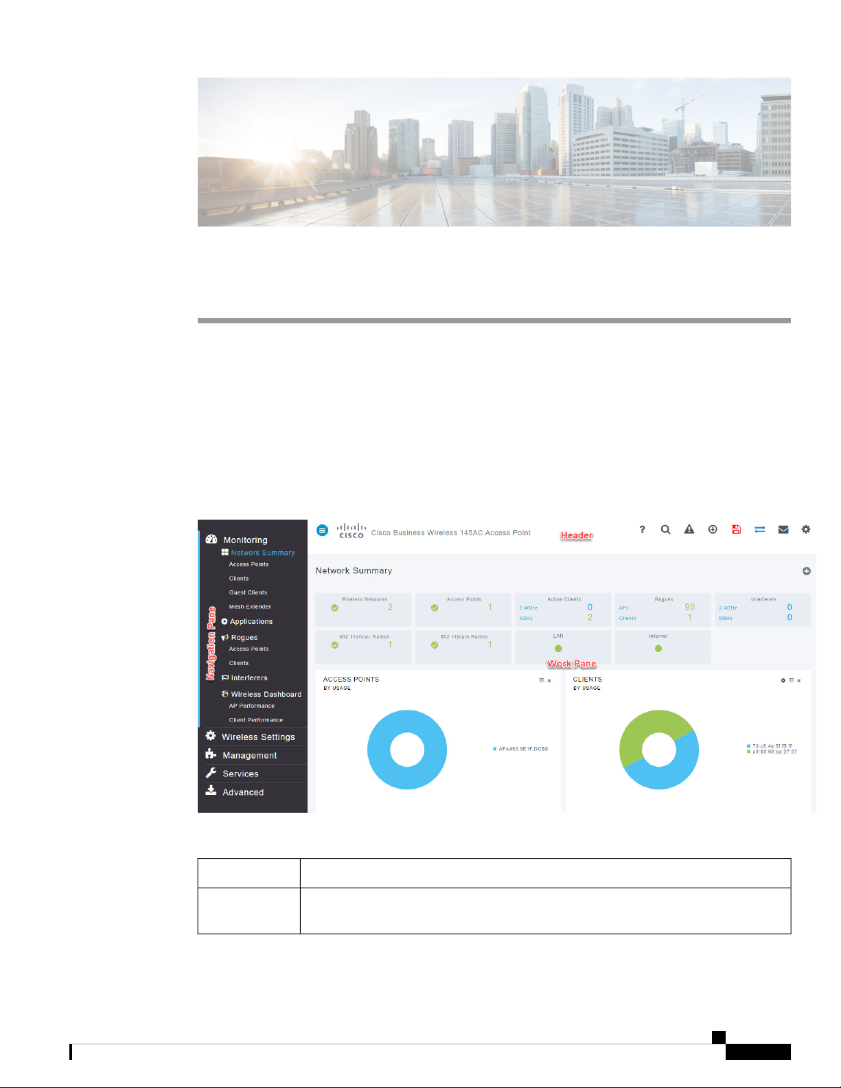
Using the Cisco Business Wireless Access Point GUI
Overview of the Cisco Business Wireless Access Point GUI with a description of the navigation pane links
Home window
Table 2: Cisco Business Wireless Access Point Home Page
DescriptionName
Navigation pane
Provides access to the Cisco Business Wireless features. Each of these main feature tabs
comprises of sub-level tabs. Click to expand and view the sub-level tabs.
Cisco Business Access Point Administration Guide, Version 10.0.1.0
5
Page 18
Using the Cisco Business Wireless Access Point GUI
DescriptionName
Using Cisco Business Wireless Access Point GUI
Work pane
Area where the feature interface is displayed.
When you click an option in the Navigation pane, its corresponding window opens in
this area.
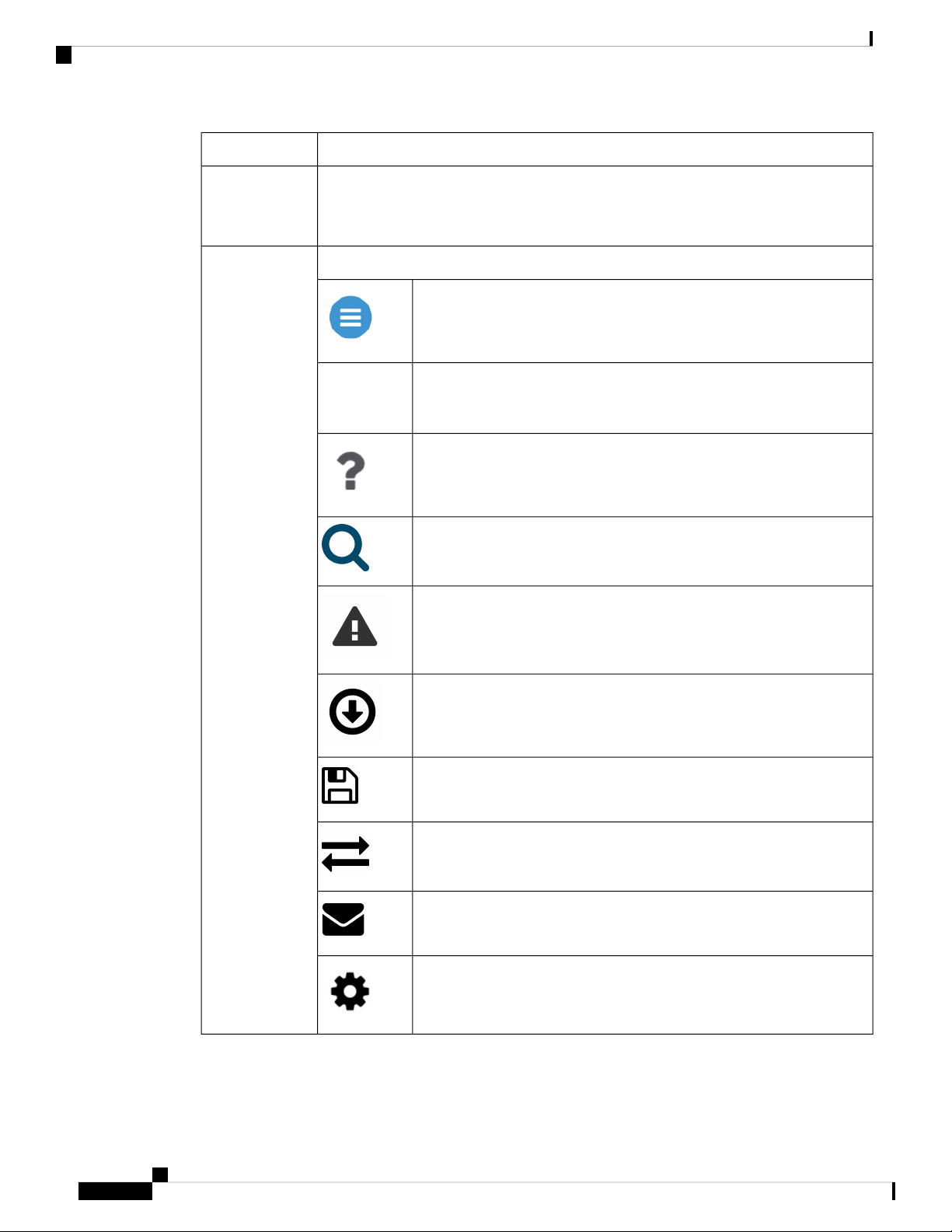
The header toolbar contains the following options:Header toolbar
A hamburger icon (toggle button) for expanding and collapsing the
navigation pane.
Cisco
Product
Name
Header title is the title of the web interface which indicates the AP model
of the Master AP (on which the integrated CBW AP functionality is
currently operating).
Click the help icon (?) to view the Cisco Business Access Point
Administration Guide document.
A search icon for searching an AP or client using its MAC address.
A notification icon that indicates if there was an incident of system crash
or if a core dump is present.
A download icon that indicates if a new software update is available for
your CBW APs on cisco.com. You may click this icon to redirect to the
software update page in the UI and download the latest firmware.
A save icon to save the current CBW AP configuration to the NVRAM.
For more details, see Saving the Master AP Configuration, on page 99.
A bi-directional icon to switch to Expert View to access advanced user
options. The default is set to standard view.
Click this mail icon to send your feedback to Cisco Business Wireless
Team.
A gear icon to view the current system information or to log off the Master
AP web interface. It also specifies the username of the user who has logged
into the application.
Cisco Business Access Point Administration Guide, Version 10.0.1.0
6
Page 19
Using Cisco Business Wireless Access Point GUI
Navigation Pane Options
The Navigation pane provides options to access the main Cisco Business Wireless Access Point features.
Each of these options comprises several sub-options to perform various other tasks.
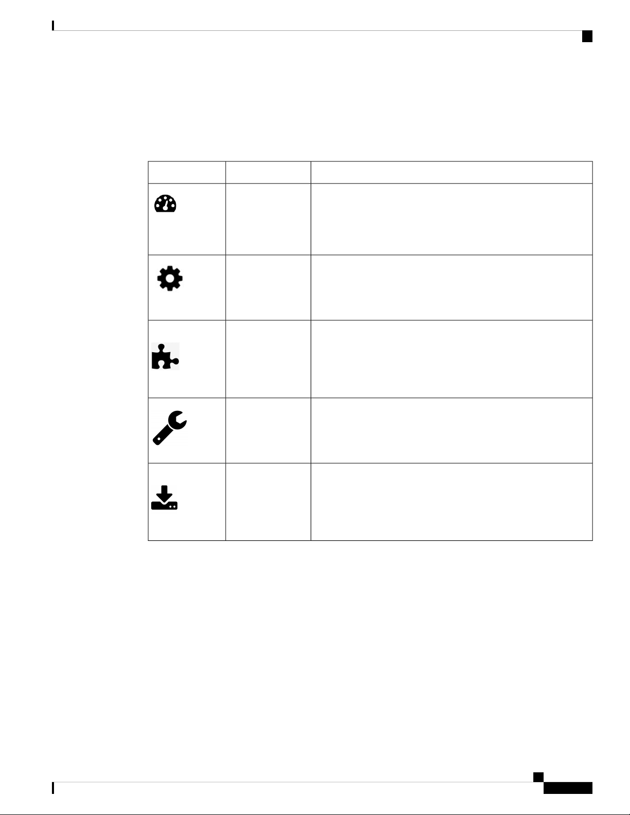
Table 3: Navigation Pane Options
Using the Cisco Business Wireless Access Point GUI
DescriptionNameIcon
Monitoring
Wireless Settings
Management
Services
Advanced
The Monitoring feature allows the Master AP to monitor WLANs
and all the connected devices on the network. It also helps to view
the performance of your APs, clients and guest clients in the network.
For more details, refer to About the Cisco Business Wireless AP
Monitoring Service, on page 17 in this guide.
The Wireless Settings page is used to administer associated APs,
manage WLANs, WLAN user accounts, and guest user accounts.
For more details, refer to About WLANs and RLANs in CBW Access
Point Network, on page 35 in this guide.
The Management page allows you to set management access
parameters, manage admin accounts, manage network time, and
perform software updates.
For more details, refer to Setting Up Management Access Interface,
on page 63 in this guide.
The Services page provides the mDNS service discovery feature
and the Cisco Umbrella network security feature.
For more details, refer to About Multicast Domain Name System,
on page 81 in this guide.
The Advanced page provides the capability to set SNMP, syslog,
and log configuration settings and to perform a reset to factory
default.
For more details, refer to the Advanced, on page 89 section in this
guide.
Cisco Business Access Point Administration Guide, Version 10.0.1.0
7
Page 20

Using the Cisco Business Wireless Access Point GUI
Using Cisco Business Wireless Access Point GUI
Cisco Business Access Point Administration Guide, Version 10.0.1.0
8
Page 21

CHAPTER 3
Getting Started
This chapter contains the following sections:
• Prerequisite for Setting up and Accessing Cisco Business Wireless AP, on page 9
• AP Deployment Models, on page 10
• Launching the Setup Wizard, on page 11
• Using the Setup Wizard, on page 12
• Logging into the Cisco Business Wireless AP, on page 14
• Adding New Subordinate APs, on page 15
• Adding Mesh Extenders, on page 15
Prerequisite for Setting up and Accessing Cisco Business Wireless AP
• Ensure that there is no Master AP running in the network other than the CBW AP during setup or daily
operation of a CBW AP network. The Cisco Master AP cannot inter-operate or co-exist with other Master
APs in the same network.
• Decide on the first access point (AP) to be set up. The first AP to be set up should be the one that supports
the Master AP functionality. This is to ensure that this AP can act as the Master AP, and the other APs
can then connect to it as Subordinate APs. This will ensure that the pre-defined CiscoBusiness-Setup
Service Set Identifier (SSID) is broad-cast only by the master AP and not by other APs.
• Ensure that the AP is properly installed as per its Quick Start Guide.
• The initial setup of the CBW AP can be done through the Master AP Setup Wizard and over Wi-Fi or
using Cisco Business Mobile App.
• You require a Wi-Fi-enabled laptop to connect to the pre-defined CiscoBusiness-Setup SSID broadcasted
by the Master AP. You cannot access this SSID through a wired network.
Note
Only one client is allowed to connect to the Ciscobusiness-Setup SSID for security
purposes. If connection is refused, another device may have joined automatically.
In this case, you should reboot the AP.
Cisco Business Access Point Administration Guide, Version 10.0.1.0
9
Page 22

AP Deployment Models
• Your laptop should have a compatible browser. For a list of browsers compatible with the CBW AP web
user interface (UI), see Supported Browsers, on page 2.
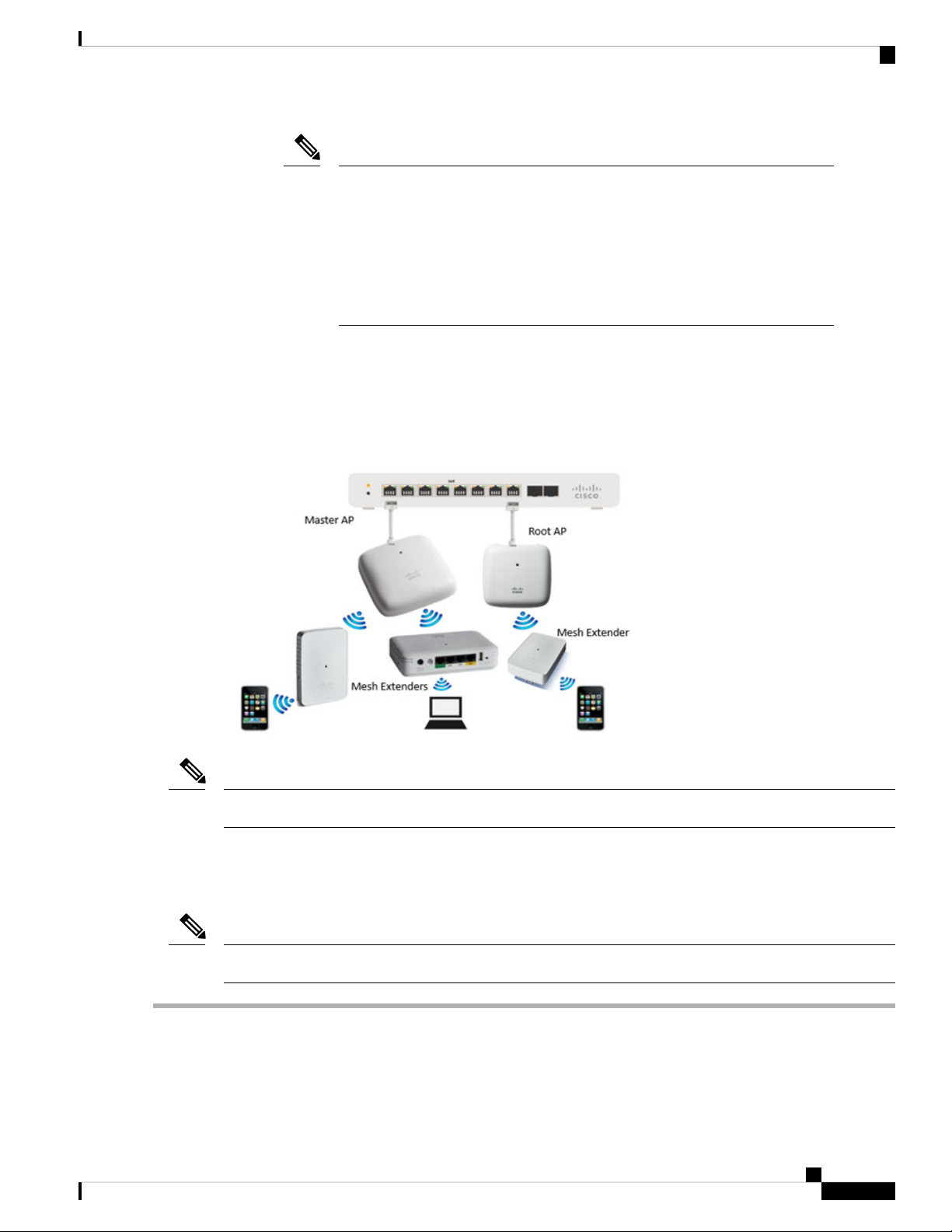
AP Deployment Models
The following deployment models are supported in the Cisco Business Wireless AP network:
• Non-Mesh deployment (wired deployment only)— All the APs in the CBW AP network have a Wired
Uplink. The supported APs in the network are master capable. One among them will serve as a Master
AP and the other APs (referred to as Subordinate APs) in the CBW network will join the Master AP.
The APs will act in AP-only mode.
Supported APs (Master APs)— CBW140AC, CBW145AC, CBW240AC.
Getting Started
Note
Ensure that the switch is in turn connected to the router for internet access.
• Mesh deployment (wireless deployment with single/multiple wired uplink APs)— In this deployment
model, the CBW AP network comprises of both Master AP and Subordinate APs (wired APs and wireless
Mesh Extenders). The APs that have a wired uplink (includes the Master AP) acts as Root AP (RAP) to
which the Mesh Extenders (MAP) joins wirelessly. Master AP will act in Bridge mode. To setup this
deployment, refer to the section, About Cisco Mesh. For Associating the wireless Mesh Extenders to the
network, add the Ethernet MAC address of the Extenders in the local MAC address table of the Master
AP. For details, refer to Adding Mesh Extenders, on page 15. Wireless Mesh Extenders have the dynamic
algorithm to select the best RAP based on the signal strength and join the same.
Note
Ensure that you enable Mesh while configuring the Initial Setup Wizard for
this deployment model.
Cisco Business Access Point Administration Guide, Version 10.0.1.0
10
Page 23
Getting Started
Launching the Setup Wizard
Note
Only Mesh Extenders (such as CBW141AC, CBW142AC & CBW143AC) are
required to be manually added to the auth-list. Where as, the Subordinate APs
that are non-Mesh Extenders (such as CBW140AC, CBW145AC & CBW240AC)
are connected via wired uplink and are automatically added to the auth-list.
You can obtain the MAC address by reading the QR code on the back of the
device with a QR Reader app on a mobile phone. You can also find the MAC
address at the bottom of the AP Device.
Supported APs in Mesh deployment:
• Master APs— CBW140AC, CBW145AC, CBW240AC
• Subordinate APs— CBW141ACAM, CBW142ACM, CBW143ACM, CBW140AC, CBW145AC,
CBW240AC.
Note
APs listed under Master APs can also function as Subordinate APs.
Launching the Setup Wizard
Note
You may use the Cisco Business Mobile App instead of the Web UI to run the setup wizard.
Step 1 Boot the AP that has the Master capability.
In a few minutes, the CiscoBusiness-Setup SSID starts broadcasting and the AP's status LED cycles through patterns
from red, amber and green to blinking green.
Cisco Business Access Point Administration Guide, Version 10.0.1.0
11
Page 24

Getting Started
Using the Setup Wizard
Step 2 Connect the laptop to the CiscoBusiness-Setup SSID through Wi-Fi and enter the default password: cisco123.
Note
The laptop obtains an IP address from the subnet of the Master AP.
Step 3 Launch a supported web browser, such as Chrome, Firefox, Safari or Internet Explorer.
For the Apple clients, after connecting to the CiscoBusiness-Setup SSID, the captive portal window may automatically
open with the Welcome page followed by the initial Setup Wizard.
Note
After connecting to the CiscoBusiness-Setup SSID, upon opening a web browser, you should automatically be
redirected to http://ciscobusiness.cisco. If not, go to the following step.
Step 4 In the address bar, type the URL: http://ciscobusiness.cisco and press Enter
Step 5 Click Start on the Cisco Business Wireless Access Point page to launch the Setup Wizard. You will be required to
create an admin account.
Note
Only one client can be connected to the CiscoBusiness-Setup SSID at a time.
For instructions on entering details on the Setup Wizard page, refer to Using the Setup Wizard, on page 12.
Using the Setup Wizard
The Setup Wizard helps you configure certain basic parameters on your Cisco Business Wireless AP (CBW
AP), and thereby get your AP network running.
Once you have completed the steps in Launching the Setup Wizard, on page 11, use the following sections
as a reference for the data that you enter and proceed with the configuration wizard pages.
Welcome Screen
Click the Start button in the Welcome screen. The Cisco Business Wireless Access Point page relevant to
your AP model is displayed.
1. Create an admin user account on the Master AP. You can enter up to 24 ASCII characters.
Note
The username is case sensitive and cannot be cisco or its variant.
2. Enter a password. The password can contain 8-127 ASCII characters. When specifying a password, ensure
the following:
• The password must include lowercase letters, uppercase letters, digits, or special characters. The
special characters can be ~, !, @, #, $, %, ^, &, *.
• No character in the password can be repeated more than three times consecutively.
• The new password cannot be the same as the associated username or the username reversed.
• The password cannot be cisco, ocsic, or any variant obtained by changing the capitalization of the
letters in the word Cisco. In addition, you cannot substitute 1, I, or ! for i, 0 for o, or $ for s.
Cisco Business Access Point Administration Guide, Version 10.0.1.0
12
Page 25

Getting Started
Using the Setup Wizard
3. Confirm the password and click Start.
Set Up Your Master AP
Specify the following basic parameters for setting up your Master AP:
DescriptionField
Master AP Name
Country
Date and Time
Mesh
Enter the name that you want to assign to the Master AP.
Note
A max of 24 characters is allowed.
The characters can be upper/lowercase letters,
numbers, dot, and hyphen.
The name should always start with an alphabet and
should not end with '.' or '-'.
Choose the country that matches the physical location of the
CBW AP.
Note
The CBW AP will display only countries that are
supported by the regulatory domain of the AP. You
can choose your country from the drop-down list.
There are strict regulatory rules to operate under the
proper country code during the usage.
Specify the date. By default, your device's system time is
applied. You can manually edit the date and time, if required.
Select your time zone.Timezone
To add Mesh Extenders to your AP network, enable the Mesh
option. By default this option is disabled.
Would you like Static IP for your Master
AP (Management Network)
Default Gateway
Cisco Business Access Point Administration Guide, Version 10.0.1.0
Enable this option, if you want to configure a static IP for the
management interface. If not, the interface gets an IP address
from your DHCP server (typically in your router). By default,
this option is disabled.
Note
A management IP address should be within current
subnet of your local VLAN and not in the client pool
issued by your DHCP server.
If you choose to configure the static IP, then you will
be required to enter data in the following fields. If
not, you can proceed to the next section.
Enter the IP address for managing the Master AP.Management IP Address
Enter the subnet mask for the Master AP.Subnet Mask
Enter the default gateway or router IP address for the Master
AP.
13
Page 26

Logging into the Cisco Business Wireless AP
Create your Wireless Networks
Specify the following parameters:
Getting Started
DescriptionField
Network Name
Security
Passphrase
Show Passphrase
Specify a SSID for your Wireless network. You can enter up to
31 characters in this field.
Note
By default, the SSID security is set to WPA2 Personal that uses
pre-shared key (PSK) authentication.
Specify the passphrase or the pre-shared key (PSK). The password
should contain 8 - 63 ASCII characters.
Note
Re-Enter the passphrase or the pre-shared key (PSK) here.Confirm Passphrase
Enable in order to display the passphrase in clear text for visible
confirmation.
Make a note of this SSID to connect a client and log
into the CBW web user interface which is detailed in
the later section of this chapter. For details, refer to
Logging into the Cisco Business Wireless AP, on page
14.
Make a note of this Passphrase to connect a client to
the SSID and log into the CBW web user interface
which is detailed in the later section of this chapter.
For details, refer Logging into the Cisco Business
Wireless AP, on page 14.
Once you complete the configuration settings, click Next to proceed or Back to modify the data in the previous
screens. Confirm the settings and click Apply to save the configuration.
The access point reboots. This may take up to 6 minutes. The booting process is complete when the LED is
consistently blinking green, or solid green.
Note
For a detailed explanation on the LED behavior, see, LED Color Indicators for Cisco Business Wireless APs,
on page 107.
You can now proceed to Logging into the Cisco Business Wireless AP, on page 14.
Logging into the Cisco Business Wireless AP
Once you have completed the steps in Using the Setup Wizard, on page 12, follow the subsequent instructions
to log into the CBW AP web user interface (UI). You can monitor and manage the access point and associated
devices using this web interface (UI).
Cisco Business Access Point Administration Guide, Version 10.0.1.0
14
Page 27

Getting Started
Adding New Subordinate APs
Step 1 Connect to the new SSID that you created using the Setup Wizard ->Create Your Wireless Network process.
Step 2 Open a supported web browser. In the address bar, type https://ciscobusiness.cisco or https://<ip address> and press
Enter. The Cisco Business Wireless Access Point login page is displayed.
The CBW AP uses a self-signed certificate for HTTPS. Therefore, all browsers will display a warning and ask you whether
you wish to proceed with an exception when the certificate is presented to the browser. Accept the warning in order to
access the Master AP login page.
Note
Step 3 Click Login and enter the user name and password you created during the initial Setup Wizard process to proceed with
using the web UI options.
If the Firefox browser doesn’t throw an exception, navigate to Options > Privacy & security > Certificates
> view certificates> Servers > Add exception and add an exception for https://ciscobusiness.cisco
What to do next
After you log in, the default landing page is the Network Summary window. For more information, see
About the Cisco Business Wireless AP Monitoring Service, on page 17.
Adding New Subordinate APs
If you have a CBW network up and running, then adding new wired APs to the network is easy.
Step 1 Plug the Wired uplink AP (CBW140AC, CBW145AC or CBW240AC) into the Ethernet LAN in which the current Master
AP is connected.
Step 2 The new AP will boot up, update its firmware to match the Master AP, copy the configuration information and then join
the Wireless Network.
Now, you can mange the newly added AP through the Web UI by navigating to Wireless Settings > Access Points page.
Adding Mesh Extenders
You can add a Mesh Extender such as CBW141ACM, CBW142ACM, or CBW143ACM to the Wireless
Network.
Ensure that you have enabled the Mesh option in the initial setup wizard. If not, then, go to Wireless Settings >
Mesh, enable the Mesh toggle button and click Apply. For detailed information, refer to About Cisco Mesh,
on page 57.
Now, MAC address of the Mesh Extender should be added to the Local MAC Addresses table. You can add
this using one of the following methods:
Cisco Business Access Point Administration Guide, Version 10.0.1.0
15
Page 28

Adding Mesh Extenders
Note
Getting Started
Using the Management Web UI
You must enter the MAC address of all Mesh Extenders that you want to use in the mesh network with the
Master AP. A Master AP responds only to discovery requests from indoor radios that appear in its authorization
list. To add the MAC Address in Auth-List, do the following:
1. Navigate to Wireless Settings > WLAN Users > Local MAC Addresses.
2. Click Add MAC Address.
3. Specify the MAC Addresses.
4. In the Description field, specify a description of the mesh access point. The text that you enter identifies
the mesh access point on the Master AP.
You might want to include an abbreviation of its name and the last few digits of the MAC address, such as
ap1522:62:39:10. You can also note details on its location such as roof top, pole top, or its cross streets.
5. You may now choose to join or block an Access Point using the following instructions:
• Choose the Type as Whitelist to join the access points to the Master AP.
• Choose the Type as Blacklist to block a particular access point from joining the Master AP.
Note
Blacklisting a client or Mesh Extender that is currently joined to the network will
not take effect until it attempts to rejoin the network (after disconnect or reboot).
6. Select the Profile Name from the drop-down list and click Apply. By default, the profile name is mapped
to Any WLAN/RLAN.
You may now check to see if the MAC address you added has been listed in the AP network by navigating
to Wireless Settings > Access Points. You will find the MAC address added in the column, AP Mac
along with the AP name under the AP Model column of the table.
Using the Cisco Business Mobile App
1. Connect to the SSID setup for the Master AP and log into the Master AP admin account.
2. Select Monitor my Network, then choose Add a device.
3. Scan the MAC address of the Mesh Extender using the QR code reader.
To troubleshoot issues with Mesh Extender, refer to Deployment and Troubleshooting Guidelines, on page
112.
Cisco Business Access Point Administration Guide, Version 10.0.1.0
16
Page 29

CHAPTER 4
Monitoring
This chapter contains the following sections:
• About the Cisco Business Wireless AP Monitoring Service, on page 17
• Customizing the Network Summary View, on page 18
• Customizing Access Points Table View, on page 19
• Viewing Access Point Details, on page 20
• Viewing Client Details, on page 23
• Viewing Guest Client Details, on page 26
• Troubleshooting a Client, on page 26
• Viewing Applications, on page 28
• Viewing Rogue Access Points, on page 28
• Viewing Interferer Details, on page 30
• Wireless Dashboard, on page 31
• Customizing the Access Point Performance View, on page 32
• Customizing the Client Performance View, on page 33
About the Cisco Business Wireless AP Monitoring Service
The Cisco Business Wireless AP Monitoring service enables the Master AP to monitor the WLANs and all
the connected devices on the network.
The Monitoring service offers the following capabilities through the Network Summary and Wireless
Dashboard tabs:
• View details of configured WLANs.
• View list of top WLANs based on traffic and associated clients.
• View details of APs in the network.
• View details of clients operating actively at either 2.4 GHz or 5 GHz.
• View summary of client device, guest client device, operating systems and applications running on these
devices.
• View a detailed list of rogue clients and APs.
• View details of various interferers in the network on the 2.4 GHz and 5 GHz radio frequencies.
Cisco Business Access Point Administration Guide, Version 10.0.1.0
17
Page 30

Customizing the Network Summary View
• Monitor the performance of APs in the network.
• Monitor the performance of clients and guest clients in the network.
Monitoring
Note
• All the parameters on the Network Summary page are read-only parameters.
• This page is automatically refreshed every 30 seconds.
Customizing the Network Summary View
The Network Summary page lets you view data in a graphical format. You can customize the Network
Summary view by adding or removing the widgets. The data displayed in various widgets can be viewed
either in the doughnut view format or in the tabular view format by toggling the display icon on the top right
of the individual widgets.
Note
Each of the action icons available within the widget is discussed in the Using the Widgets section.
The following widgets are displayed in the Network Summary page.
• OPERATING SYSTEMS (By clients)—Displays the OS information of the Clients (such as Linux
clients, Android clients and so on) that are connected to the WLAN. For this feature, the user has to
enable Local Profiling in the WLAN.
• GUESTS (By usage)—Displays the Top 10 guest clients in the network based on the throughput and
usage.
• ACCESS POINTS (By usage)—Displays the Top 10 access points in the network based on the number
of clients connected, usage and throughput.
• APPLICATIONS (By usage)—Displays the Top 10 applications such as gmail, youtube, facebook and
so on based on usage level of the clients connected in the network. For this feature, the user has to enable
the Application Visibility Control (AVC) option in the WLAN.
• TOP WLANS (By usage)—Displays the Top 10 WLANs in the network by usage and number of clients
connected.
• CLIENTS (By usage)—Displays the Top 10 clients in the network based on throughput and usage.
Using the Widgets
This section details the various icons/options available within the widget to customize and view data as
required.
• Use the x icon within a widget to remove the widget from the Monitoring page.
• Use the + icon on the top right to add the widget in the Monitoring page.
• Use the clear data (gear) icon to clear the usage data and reset to zero.
Cisco Business Access Point Administration Guide, Version 10.0.1.0
18
Page 31

Monitoring
• Use the tabular (graphical) toggle icon and the tabulated list toggle icon to change the display of data
between tabular view or doughnut view.
• Use the Save icon within a widget to export the top 10 entries locally in Excel format.
Note
All entries will be exported for Guests widget.
Customizing Access Points Table View
Step 1 Navigate to Monitoring > Network Summary > Access Points.
Customizing Access Points Table View
Note
Step 2 In the Access Points page, toggle between the 2.4GHz and 5GHz tabs to view a tabular listing of the access points
operating at the respective radio frequencies. The following fields are displayed:
a) AP Name—Displays the name of the access point.
b) Role—Pictorial representation of the type of AP. A Master AP is depicted with a (P) attached to the AP icon, a Mesh
c) Type—Specifies if the AP is a Master AP, Master capable AP or a Mesh Extender.
d) IP Address—The IPv4 address of the device.
e) Model—Model of the CBW AP.
f) Clients—Number of client devices connected to the access point
g) Usage—The amount of data that has transferred between access point and the client device.
h) Uptime—Duration of how long the AP has been powered up.
i) Admin Status—Displays the configured status of 2.4GHz / 5GHz Radio is enabled or disabled.
j) Operational Status—Displays the running status of 2.4GHz / 5GHz Radio.
k) Channel Utilization—Level of traffic including data and interference over the channel that is assigned on the AP.
l) Throughput(Avg)—This represents the amount of data that can be transferred from the access point to the client
m) Channel—Channel number at which the access point’s radio is broadcasting the signal.
n) Transmit Power (Avg)—The logarithmic power level at which the access point is broadcasting the signal. The values
o) Coverage Hole—Coverage holes are areas where clients cannot receive a signal from the wireless network. A
p) Interference(Avg)—RF interference involves unwanted, interference of RF signals that disrupt normal wireless
q) Noise—Noise refers to any energy interference that degrades the quality of a wireless signal. Noise can affect
You can also obtain high level details of the Access point by clicking on the count link in the Access Points
summary section under Monitoring > Network Summary page.
Extender is represented by an (E) attached to the AP icon and a Master capable AP has no letter specified to the AP
icon.
Interference includes both Wi-Fi and non Wi-Fi signals. High utilization of channel, for example above 50%, suggests
high level of interference including noise from nearby APs/clients/rogues on the same channel which results in poor
client performance. The values are represented in % format.
device.
are displayed in decibel-milliwatt (dBm) units.
coverage hole is considered to have occurred when client SNRs falls below -80dBm of data RSSI.
operations, that creates potential network latency and poor client performance. Interfering RF signals includes both
Wi-Fi and non-Wi-Fi signals. The values are represented in % format.
everything from radio transmissions to network speeds. The values are displayed in decibel-milliwatt (dBm) units.
Cisco Business Access Point Administration Guide, Version 10.0.1.0
19
Page 32

Monitoring
Viewing Access Point Details
r) Rogues—Any device that shares your channel and is not managed by your CBW network can be considered as a
Rogue.
s) MAC Address—The Unique physical address of the device.
t) Mode—Displays if the device is in AP Only mode or Mesh mode.
Step 3 You can click the downward arrow on the top right of the column headers to customize the details displayed in the table.
You may choose to hide or show the desired columns, sort them in the order you wish or filter the table contents based
on the desired parameters.
Viewing Access Point Details
Navigate to Monitoring > Network Summary > Access Points.
Click on one of the Access Point to display the Access Point View page. This page consists of the following
AP parameter details:
GENERAL
• AP Name—Displays the name of the access point.
• Location—The physical location of the access point.
• MAC Address—The Unique physical address of the device.
• Base Radio MAC—The Hardware (HW) address of 2.4 and 5GHz radios. (The address is same for both
the radios).
• IP Address—The IPv4 address is a 32-bit number that uniquely identifies an access point.
• CDP / LLDP—The name and the port of the switch to which the access point is connected.
Note
This field is applicable only for Master capable APs. (Wired uplink APs).
• Ethernet Speed—Link speed capability of the switch port.
• Model / Domain—Model of the access point / Radio domains.
• Power Status— Indicates the power level and mode of power.
• Parent MAC Address—Displays the Parent MAC address (AP to which it is connected Wirelessly)
This option is available only for Mesh Extenders.
• Serial Number— The unique number provided at the time of manufacturing.
• Max Capabilities—The radio domains, Spatial streams and maximum data rates of the access point.
PERFORMANCE SUMMARY
This table provides the following details specific to the radios:
• Number of clients—The number of client devices connected to a specific Access Point.
Cisco Business Access Point Administration Guide, Version 10.0.1.0
20
Page 33

Monitoring
Viewing Access Point Details
• Channel—Channel number at which the access point’s radio is broadcasting the signal.
Note
Number of channels will be 1, 2 and 4 for 20GHz, 40GHz and 80 GHz
respectively.
• Configured Rate—The default minimum and maximum data rates of the access point.
• Usage Traffic—The amount of data that has transferred between access point and the client device.
• Throughput—This represents the amount of data that can be transferred from the access point to the
client device.
• Transmit Power—The logarithmic power level at which the access point is broadcasting the signal.
• Noise—Noise refers to any energy interference that degrades the quality of a wireless signal. Noise can
affect everything from radio transmissions to network speeds.
• Channel Utilization—Level of traffic including data and interference over the channel that is assigned
on the AP. Interference includes both Wi-Fi and non Wi-Fi signals. High utilization of channel, for
example above 50%, suggests high level of interference including noise from nearby APs/clients/rogues
on the same channel which results in poor client performance.
• Interference—RF interference involves unwanted, interference of RF signals that disrupt normal wireless
operations, that creates potential network latency and poor client performance. Interfering RF signals
includes both Wi-Fi and non-Wi-Fi signals.
• Traffic—Shows the data traffic in 2.4GHz and 5GHz radio.
• Admin Status—Status of the Radios for 2.4 GHz and 5 GHz.
• Interferer Detection—Status of Interferer detection for 2.4GHz and 5GHz radios.
{AP Name} DETAILS
This table provides the following details specific to the Access Point:
• CLIENTS—This table shows the client details that are connected to it. For per field details refer “Viewing
the details of the Clients” section.
• RF TROUBLESHOOT—Displays a visual graphical representation of parameters that can affect the
radio performance of the access points, such as:
• NEIGHBOR AND ROGUE APS—Displays the Neighbor and Rogue APs on the current and
adjacent channels for a given radio and the signal strength they are heard at. This visualization
allows you to quickly identify the Neighbor and Rogue APs that are heard above −70dBm which
causes interference and reduces the overall RF performance for the cell. Neighbor and Rogue APs
that are heard below −70dBm are not displayed.
• CLEAN AIR INTERFERERS—Displays the sources of non Wi-Fi interferers and their severity
on the current and adjacent channels for a given radio. This visualization allows you to quickly
identify non Wi-Fi sources of interference that are reducing the overall RF performance for the cell.
• CLIENT DISTRIBUTION ON TOP NEIGHBOR APS—Displays the top 5 neighbor AP with
signal strength greater than −70 dBm on the APs current client serving channel (2.4 GHz and 5GHz).
Cisco Business Access Point Administration Guide, Version 10.0.1.0
21
Page 34

Viewing Access Point Details
Tx power and number of clients associated to this AP and its neighbor APs are shown. Number of
clients is not available for neighbor APs on different Master AP.
• CLIENT DISTRIBUTION BY DATA RATES—Each client's throughput varies depending on
the data rate it is using (802.11 a/b/n/ac) at any given point in time, and this data rate may vary every
second. Various factors such as RSSI values, RF interference, etc. may affect a client device's
instantaneous data rate.
• SPECTRUM INTELLIGENCE
Note
By default Spectrum Intelligence (SI) is disabled in order to reduce the CPU
cycles and increase the performance.
You can enable the SI for the radio using the following instructions:
Ensure that you enable the Interferer detection globally under Advanced > RF
Optimization(in Expert View).
Navigate to Wireless Settings > Access Points and select an AP. Click Edit
and choose either 2.4GHz or 5GHz radio.
Monitoring
• ACTIVE INTERFERERS—Displays the Active Interferers for Access point for the selected radio.
For further details of the table refer Viewing Details of Interferers under Viewing Interferers.
• NON WI-FI CHANNEL UTILIZATION—Displays the Non Wi-fi Channel Utilization for the
Access point of the selected radio.
• INTERFERENCE POWER—Shows the Interference Power for the Access point on the selected
radio.
• TOOLS
This section in the UI consists of options to configure the LED states of the access points and also provides
details of the image in the description table:
• AP LED DISABLE—To configure LED, refer to the LED Display Settings, on page 110.
• BLINK AP LED— The Blink AP LED function causes the LED to blink Red/Amber/Green for
60 seconds. This is used to identify the AP. To configure LED, refer to the LED Display Settings,
on page 110.
• RESTART AP—You can reload AP if needed. The AP which acts as a Master AP does not have
this option.
• INTERCHANGE IMAGE—You can swap the primary version and backup version of the image.
This will take effect only after the AP reloads.
• Description Table Details
Description
The default active image version of the Master AP.Master AP Primary Image
The backup image version of the Master AP.Master AP Backup Image
Cisco Business Access Point Administration Guide, Version 10.0.1.0
22
Page 35

Monitoring
Viewing Client Details
Description
The active image version of the access point.AP Primary Image
The backup image version of the access point.AP Backup image
Predownload status
Predownloaded version
If the access point is going for an software update the
corresponding predownload status is displayed.
Version of the predownloaded image during software upgrade
process.
Viewing Client Details
Step 1 Click Monitoring > Network Summary.
A summary of all active clients is displayed in the Active Clients summary section. These clients are either 802.11b/g/n
clients operating at 2.4 GHz or 802.11a/n/ac clients operating at 5 GHz.
Note
Step 2 In the Active Clients summary section, click the count display icon to view high-level details of the client device or
navigate to Monitoring > Network Summary > Clients. This section will give you an overview of the connected clients
and its parameters as explained below:
In the Clients page, there are three upper blocks that list the following details:
You can also view this page by navigating via Monitoring > Network Summary > Clients.
• Clients—This tile displays the total number of clients connected.
• Wireless—This tile displays the number of clients specific to 2.4 GHz and 5 GHz radio.
• Apple—This tile is specific to the Apple Clients. Specifies the number of clients.
• Fastlane—This tile displays the number of fastlane using clients. Fastlane allows iOS apps connected to CBW
access points to be prioritized. This means your voice, video and real-time data gets to be first in line. To enable
Fastlane go to Wireless Settings > WLANs > Add/edit WLAN > Traffic Shaping > Fastlane.
• Analytics—This tile displays the number of Analytics capable clients.
Click on the required client from the list in the table displayed to view the per client details. The following details are
displayed:
Client Details Table
You can click the downward arrow on the top right of the column headers to customize the details displayed in the table.
You may choose to hide or show the desired columns, sort them in the order you wish or filter the table contents based
on the desired parameters.
• User Name—The user name of the client connected to the Master AP (Default: Unknown).
• IPv4 Address— The IPv4 address is a 32-bit number that uniquely identifies the client device.
• AP Name—The configured AP name to which the client associated will be displayed in this column.
Cisco Business Access Point Administration Guide, Version 10.0.1.0
23
Page 36

Viewing Client Details
• Protocol—The WiFi standard through which the client is connected. It can be 802.11a/b/g/n/ac.
• Hostname—The MAC address of the client is displayed by default. Enable Wireless Settings > Add/Edit WLAN >
Local Profiling to view the hostname of the clients supported.
• Client Type—The Capable Client’s operating systems will be displayed in this column as Android, Apple-Device
etc.,
• Connection Speed—The maximum data rate strength of the client connected to the access point. The values are
displayed in units of Mbps.
• Status—The active status of the client.
• Signal Quality—Signal quality is a value ranging from 0 to 100 dB. This includes, the noise generated by interference
sources and the signal strength.
• Signal Strength—Signal strength is the wireless signal power level received by the wireless client. Strong signal
strength results in more reliable connections and higher speeds. Signal strength is represented in -dBm format, ranges
from 0 to -100dBm. The closer the value to 0, the stronger the signal.
• Usage—The amount of data consumed by the client
Monitoring
• WLAN SSID—Shows to which SSID the client has connected
• Uptime—The duration of how long the client is connected to the access point
• Mac Address—The MAC(Hardware) address of the client connected
• Frequency Bandwidth—The radio on which the client is connected 2.4 GHz or 5 GHz
• WLAN Profile—The profile name of the configured WLAN to which the client is connected
• AP MAC—Radio MAC address of the corresponding access point to which the client is connected
• AP Group—This column shows the access points groups to which it is configured
• IPv6 Address—This is the IPv6 address of the client device.
Client View
Select a required client from the list displayed to view the following details:
• GENERAL
a. User Name—The user name of the client connected to the Master AP (Default: Unknown).
b. Hostname—The MAC address of the client is displayed by default. Enable Wireless Settings> Add/Edit
WLAN> Local Profiling to view the hostname of the clients supported.
c. MAC Address—The MAC(Hardware) address of the client connected .
d. Deauthenticate—Click this option to disconnect the client.
Note
Deauthenticating the client removes a client from the WLAN, but that client will be able to rejoin
unless their MAC address is added to the Black list.
To block the client permanently, navigate to Wireless Settings > WLAN Users > Local MAC
Addresses, click Add MAC address, select Blacklist as the type and hit Apply & Save.
e. Uptime—The duration of how long the client is connected to the access point.
Cisco Business Access Point Administration Guide, Version 10.0.1.0
24
Page 37

Monitoring
Viewing Client Details
f. SSID—Shows to which SSID the client has connected.
g. AP Name—The configured AP name to which the client is associated. The AP name along with the location
can be configured by navigating to Wireless Settings > Access Points.
h. Nearest APs—List of AP names nearer to the client based on signal strength.
i. Device Type—The Capable Client’s operating systems will be displayed in this column as Android, Apple-Device
etc.,
j. Performance—This shows the Signal Strength, Signal Quality, Connection Speed, Channel Width.
k. Capabilities—This gives information on which domain the client is associated to the AP and its Spatial Stream.
l. Cisco Compatible—Cisco Compatible state changes only when a Cisco client (which supports CCX extensions
of the IEEE standards) get associated to your access point.
m. Client connection score—Connection score is the percentage based connection quality between client and the
access point. It denotes the current client data transfer speed. Higher the percentage, the faster and higher the
data transferred. This value is based on the Client Actual Rate divided by either the Client Max Capability or
Max AP Configured (whichever is lower).
• CONNECTIVITY GRAPHIC—This line graph represents the stages and current status of the associated client as
Start, Association, Authentication, DHCP, and Online.
• TOP APPLICATIONS—The top applications that are being used by the client device is presented in a graphical or
tabular format. To utilize this, the user must enable AVC in Wireless Settings> WLANs > > Add/Edit WLAN >
Traffic Shaping > Application Visibility Control.
Note
Ensure that the Application Visibility Control (AVC) is active under WLAN settings to view this data.
• MOBILITY STATE—This shows the graphical flowchart of stages on how the client is connected to the Master
AP.
• Name of the Master AP, with its IP address and the model number of the AP on which it is running.
• Name of the AP with which the client is connected to the Master AP, the AP's IP address, and the AP's model
number.
• Nature of connection between the AP and the client. For example, wireless 802.11n 5 GHz connection.
• Name of the client, type of client (such as Microsoft Workstation), VLAN ID of the client, and the client's IP
address.
• NETWORK & QOS —This shows client capability of some IEEE standards and user configured parameters such
as IP address, VLAN, Source Group Tag, Fastlan Client, Mobility Role, WMM, U-APSD and QoS Level.
• SECURITY & POLICY—This table shows the encryption type and security policies on which the client is associated
to the access point such as Policy (WPA2), Cipher, Key Management, EAP Type, ACL, mDNS, and AAA Role.
Cisco Business Access Point Administration Guide, Version 10.0.1.0
25
Page 38

Monitoring
Viewing Guest Client Details
Viewing Guest Client Details
The clients that are connected to the Guest WLANs are known as Guest Clients. To obtain Guest WLANs
the master AP provides guest user access on WLANs which are specifically designated for use by guest users.
The concept of creating Guest WLANs is discussed in the later chapters.
Step 1 Click Monitoring > Network Summary > Guest Clients.
A summary of all active guest clients is displayed in the Guest Clients summary section. These clients are either
802.11b/g/n clients operating at 2.4 GHz or 802.11a/n/ac clients operating at 5 GHz.
Step 2 In the Guest Client page, the summary blocks display the number of guest clients and recently connected clients to the
Master AP. Each guest client detail can be viewed by clicking the specific client record.
In the Guest Clients page, there are two upper blocks that list the following details:
• Guest Clients / Recent Clients—Specifies the total number of guest clients and recent clients connected.
• Wireless—Specifies the number of 802.11b/g/n guest clients connected and operating either at 2.4 GHz or 5 GHz.
Click on the required guest client from the list in the table displayed to view the per guest client details. For a description
of the parameters displayed for a specific guest client, refer to Viewing Client Details:
Step 3 You can click the downward arrow on the top right of the column headers to customize the details displayed in the table.
You may choose to hide or show the desired columns, sort them in the order you wish or filter the table contents based
on the desired parameters.
Note
The clients connected to Guest WLANs are considered to be Guest Clients.
You can export details of all the guest clients connected to the CBW network and download in Excel format
using the save icon in the Guest Widget.
Troubleshooting a Client
This section describes in detail how to perform a client ping test and a connection test. These help to effectively
investigate and troubleshoot connection issues.
To troubleshoot wireless client joining issues, set the Logging level as Notifications (5) and check the logs
in the Master AP UI under Management > Logging.
Performing a Client Ping Test
You can perform a ping test on the client to determine the latency or delay between the Master AP and the
client. This is an Internet Control Message Protocol (ICMP) based test. Using the ping test you can know the
connectivity as well as the latency between the Master AP and the client.
Click Start to begin the test. The latency in milliseconds is represented graphically.
Cisco Business Access Point Administration Guide, Version 10.0.1.0
26
Page 39

Monitoring
Performing a Connection Test
Performing a Connection Test
You may choose to perform a Connection test when the client fails to connect to a particular WLAN. This
test takes about three minutes. Attempting to connect during the three minute test period will generates
diagnostic information to aid in troubleshooting connection issues.
Step 1 Go to Monitoring > Network Summary > Clients.
Step 2 Click on the client MAC address that you want to debug from the list of clients that are available.
Step 3 Scroll down to the Client Test and in the Connection tab click Start.
Step 4 Now disconnect the client from the WLAN and try re-connecting.
Step 5 The result at each stage of client connection establishment with the WLAN is displayed.
Generating an Event Log
The user may choose to perform a complete debug session by enabling the Event Log feature that is available
in the per client view tab. The Event Log testing contains the time-stamp and message details that are exchanged
between the client and the access point. The message type helps to analyze and conclude if a client is able to
successfully join a WLAN or a reason for its failure in joining a particular WLAN.
Step 1 Go to Monitoring > Network Summary > Clients.
Step 2 Click on the client MAC that you want to debug.
Step 3 Scroll down to the Client Test and in the Event Log tab, click on the Start option.
Step 4 Now, disconnect the client from the WLAN and try to re-connect it again.
Step 5 You can also save the results, by selecting the Save to Disk option in the Master AP UI. Following is a sample output
displayed when you generate an event log:
Cisco Business Access Point Administration Guide, Version 10.0.1.0
27
Page 40

Monitoring
Viewing Mesh Extender
Viewing Mesh Extender
Step 1 Navigate to Monitoring > Network Summary > Mesh Extender.
Step 2 In the Mesh Extender page, you can view the following details of the Mesh Extenders connected to the Master AP:
• AP name—Displays name of the Mesh Extender.
• AP Model—Displays the model of Mesh Extender.
• Ethernet MAC—Displays the Hardware MAC of the Mesh Extender.
• Parent AP Name—Displays the AP name to which the Mesh Extender has joined wirelessly.
• Hop—Displays the count of how far the Mesh Extender is operating from the Master.
• Link SNR (dBM)—– It’s the signal to noise ratio calculated between the Mesh Extender and the Parent AP (to
which the Mesh has joined).
• Channel Utilization (%)—Level of traffic including data and interference over the channel that is assigned on the
AP. The values are represented in % format.
• Channel—Channel number at which the Mesh Extender’s radio is operating.
• Clients—Total number of clients connected to this Mesh Extender.
Viewing Applications
Click the Applications menu to view the Top 10 application usage in the client traffic. This can be seen when
you enable the Application Visibility Control (AVC) option in at least one WLAN. Navigate to Wireless
Settings > WLANs > Add/Edit WLAN > Traffic Shaping > Application visibility Control to view.
Viewing Rogue Access Points
Any device that shares your channel and is not managed by you can be considered as a Rogue. This includes
Rogue Access Points, Wireless Routers and Rogue clients. CBW APs have the in-built intelligence to detect
rogue devices in both 2.4GHz and 5GHz radios.
You can view the following details of rogue devices which includes unmanaged neighboring Clients and
Access Points.
• MAC Address—Rogue AP’s MAC address.
• SSID—The name of the SSID, using which the Rogue AP is broadcasting.
• Channels—The channel in which the Rogue AP is operating.
• Radios—Displays the number of radios in which the Rogue AP is detected. If the Radios count is 1, then
the Rogue AP is detected either in one of the radios (either 2.4GHz or 5GHz). If the count is 2, then the
Rogue AP is detected in both the radios.
Cisco Business Access Point Administration Guide, Version 10.0.1.0
28
Page 41

Monitoring
Configuring the Rogue AP States
• Clients—Number of clients connected to the Rogue AP.
• Class—The class of the Rogue AP. By default, all the Rogue APs are unclassified. You can change the
class of Rogue APs as Friendly, or Malicious.
Following are the classes that are supported by the CBW:
DescriptionClass
Unclassified
The CBW AP discovers all the Rogue APs and marks them under the
Unclassified class by default. Also, the status of the Rogue AP remains as
Alert since it remains unknown to the CBW network.
Friendly
You can move the Rogue AP to a Friendly state if you know the Rogue
APs MAC.
Following are the options that are configurable:
• Internal—If the unknown access point is inside the network and poses
no threat to WLAN security, you would manually configure it as
Friendly, Internal. Example: An access point that exists within your
premises.
• External—If the unknown access point is outside the network and
poses no threat to WLAN security, you would manually configure it
as Friendly, External. Example: An access point that belongs to a
neighboring coffee shop.
Malicious
You can move the Rogue AP to Malicious class when you do not know
the particulars of the AP. By default, the status remains as Alert since it
remains unknown to the CBW network.
• State—Displays the state of the Rogue AP. If the Rogue AP class is friendly, the state will be Internal
or External, else the state will be Alert.
Configuring the Rogue AP States
Step 1 Click Monitoring > Network Summary
Step 2 In the Rogues tab, click on the Access Points.
Step 3 Click on one of the available Rogue APs that is detected by the CBW.
Step 4 In the Update class drop-down list box, select the appropriate class.
Step 5 Select the class as Friendly to configure the status as Internal or External.
Step 6 If you specify the AP as Malicious class, then the status of the AP remains as Alert.
Step 7 You can also move an AP from one state (such as Friendly) to another (such as Malicious) by selecting the AP from the
specific tabs.
Step 8 Click Apply to save the changes.
Cisco Business Access Point Administration Guide, Version 10.0.1.0
29
Page 42

Viewing Rogue Client Details
Viewing Rogue Client Details
Step 1 Navigate to Monitoring > Rogues > Clients.
Step 2 Clients that are associated to Rogue APs are displayed along with the following details:
• MAC address—Rogue client’s MAC address.
• AP MAC—MAC address of the AP to which the Rogue client is connected.
• SSID—Displays to which SSID the client is connected.
• Radios—Displays the number of radios in which the Rogue client is detected
• Last Seen—Shows the time at which the Rogue client is detected.
• State—Displays the state of the Rogue client.
• Wired—Specifies if the detected Rogue client is Wired or Wireless
Monitoring
Viewing Interferer Details
Interferers are non-Wi-Fi devices that cause disruption to your Wireless network. They may either be operating
at 2.4 GHz or at 5 GHz. To view these devices, do the following:
Step 1 Click Monitoring > Network Summary > Interferers.
A summary of all non-Wi-Fi interfering devices is displayed in the Interferers summary window. These interferers may
either be operating at 2.4 GHz or at 5 GHz.
Step 2 In the Interferers summary window, click the count display icon. The following details are displayed.
• AP Name—The name of the access point where the interference device is detected.
• Radio Slot—Slot where the radio is installed.
• Interferer Type—Type of the interferers such as Microwave Oven, Jammer, WiMax Mobile, and so on
• Affected Channel—Channel that the device affects.
• Detected Time—Time at which the interference was detected.
• Severity—Severity index of the interfering device.
• Duty Cycle (%)—Proportion of time during which the interfering device was active.
• RSSI—Receive signal strength indicator (RSSI)of the access point.
• Dev ID—Device identification number that uniquely identified the interfering device.
Cisco Business Access Point Administration Guide, Version 10.0.1.0
30
Page 43

Monitoring
• Cluster ID—Cluster identification number that is unique which identifies the type of the device.
Wireless Dashboard
This page displays the capabilities of AP and the Client for 2.4 GHz and 5 GHz. You can click the Close
Widget (X) icon on the top right of the following widgets that you want to remove. You may add the closed
widget again by clicking the + icon if you wish.
AP CAPABILITY
Displays the capability details for the APs managed by the Master AP:
• Max Configured Connection Rates: Displays the graph and table for maximum configured connection
rate in Mbps, mapped to different ranges, for each of the radios (2.4 GHz and 5GHz) for all the APs
configured by the Master AP.
Wireless Dashboard
• AP Distribution by Channel Width: Displays the graph and table for the maximum configured Channel
Width for all the APs configured by the Master AP.
CLIENT CAPABILITY
Displays the capability data for the clients managed by the Master AP:
• Client Capability by Spatial Stream: Displays the graph and table for the number of clients capable of a
particular spatial stream for all the clients connected to the Master AP.
• Client Capability by Max Protocol: Displays the graph and table for the number of client based on the
maximum data rate protocol supported for all the clients connected to the Master AP.
AP PERFORMANCE-CHANNEL UTILISATION
Display the Performance details for the APs managed by the Master AP:
• Channel Utilization : Displays the graph and table for the channel utilization as a percentage, mapped to
different ranges, for each of the radios(2.4 GHz and 5GHz) for all the APs configured by the Master AP.
CLIENT PERFORMANCE
Displays the connected characteristic for the clients managed by the Master AP:
• Client by Connection Score: Displays the connection score percentages ranges for all the clients connected
to the Master AP. The Connection Score is calculated as a percentage value based on the Client Actual
Rate divided by either Client Max Capability or Max AP Configured (whichever is lower). This ensures
the Connection Score is always calculated based on the maximum possible rate based on each devices
maximum rate capability.
• Client by Connected Protocol: Displays the graph and table for the number of client based on the connected
protocol for all the clients connected to the Master AP.
Cisco Business Access Point Administration Guide, Version 10.0.1.0
31
Page 44

Customizing the Access Point Performance View
AP DISTRIBUTION
Displays the distribution of APs managed by the Master AP:
• AP distribution by Model: Displays the graph and table for all APs configured by the Master AP. Based
on the Model name of the AP to the radios(2.4 GHz and 5GHz) the graph and table gets updated.
• AP distribution by SpatialStream: Displays the graph and table for all APs configured by Master AP.
Based on the SpatialStream to which it is connected for each of the radios(2.4 GHz and 5GHz) the graph
and table get updated. The centre of the donut displays the maximum number of APs with the particular
SpatialStream.
Customizing the Access Point Performance View
You can customize the AP Performance view by adding or removing the widgets.
Table 4: Wireless Dashboard - AP Performance
DescriptionWidgets
Monitoring
CHANNEL UTILIZATION
-TOP APS
INTERFERENCE -TOP APS
CLIENT LOAD -TOP APS
COVERAGE-BOTTOM APS
AP Join Failure Status
Level of traffic including data and interference over the channel that is
assigned on the AP. Interference includes both Wi-Fi and non Wi-Fi signals.
High utilization of channel, for example above 50%, suggests high level
of interference including noise from nearby APs/clients/rogues on the same
channel which results in poor client performance. Click to view the AP
detail.
RF interference involves unwanted, interference of RF signals that disrupt
normal wireless operations, that creates potential network latency and poor
client performance. Interfering RF signals includes both Wi-Fi and non
Wi-Fi signals. Click to view the AP detail.
Load indicator displays current number of connected clients on each access
point. Higher load may impact performance, using client load balancing
you can improve client distribution on the wireless network. Click to view
the AP detail.
Coverage holes are areas where clients cannot receive a signal from the
wireless network. A coverage hole is considered to have occurred when
client SNRs falls below a predetermined level. A coverage hole event is
when several clients are stuck in the same coverage hole.
This widget shows the number of APs that failed to join the Master AP and
the associated error types during a specific day, week or month. Click a
specific join error to see the APs that have failed to join the Master AP
with the associated error type. Click the setting to clear the AP Join statistics.
You can view the above statistics in both 2.4GHz and 5 GHz type of radios by clicking on them respectively.
Cisco Business Access Point Administration Guide, Version 10.0.1.0
32
Page 45

Monitoring
Adding Widgets
Step 1 Choose Monitoring > Wireless Dashboard > AP Performance.
Step 2 Click the + (plus) icon on the top right of the AP Performance window.
Step 3 Select the widgets you want to add from the following:
• Channel Utilization—Top APs
• Interference—Top APs
• Client Load—Top APs
• Coverage—Bottom APs
• AP Join Failure Status—Bottom APs
Adding Widgets
Note
Step 4 Click Close. The AP Performance window is refreshed with the new widgets.
• Top APs—AP with the maximum client load.
• Bottom APs—AP with low SNR values for the client.
Removing Widgets
Step 1 Choose Monitoring > Wireless Dashboard > AP Performance.
Step 2 Click the Close Widget (X) icon on the top right of the widgets that you want to remove. You may add the closed widget
again by clicking the + icon if you wish.
Customizing the Client Performance View
You can customize the Client Performance view by adding or removing the widgets.
Table 5: Client Performance
Signal Strength
Connection Rate
DescriptionNumbers & Labels
Strong signal strength results in more reliable connections and higher speeds. Signal
strength is represented in -dBm format, ranges from 0 to -100dBm. The closer the value
to 0, the stronger the signal. Click to get a summary of clients.
Each client's throughput varies depending on the data rate used (802.11 a/b/n/ac) at any
time, and this data rate may vary every second. Various factors such as RSSI values,
RF interference, and so on, may affect a client device's instantaneous data rate.
Cisco Business Access Point Administration Guide, Version 10.0.1.0
33
Page 46

Adding a Widget
Monitoring
DescriptionNumbers & Labels
Signal Quality
Signal quality is a value ranging from 0 to 100 dB. This includes the noise generated by
interference sources and the signal strength.
Displays clients associated with the access points of any connectivity types.Client Connections
Adding a Widget
Step 1 Choose Monitoring > Wireless Dashboard > Client Performance.
Step 2 Click the Add Widget icon on the top right of the Client Performance window.
Step 3 Select the widgets you want to add from the following:
• Signal Strength
• Signal Quality
• Connection Rate
• Client Connections
Step 4 Click Close. The Client Performance window is refreshed with the new widgets.
Removing a Widget
Step 1 Choose Monitoring > Wireless Dashboard > Client Performance.
Step 2 Click the Close Widget(X) icon on the top right of the widgets and select the ones you want to remove. You may add
the closed widget again by clicking the + icon if you wish.
Cisco Business Access Point Administration Guide, Version 10.0.1.0
34
Page 47

CHAPTER 5
Wireless Settings
This chapter contains the following sections:
• About WLANs and RLANs in CBW Access Point Network, on page 35
• Setting Up WLANs RLANs and WLAN Users, on page 35
• Managing Associated Access Points, on page 50
• Setting a Login Page for WLAN Guest Users, on page 54
• About Cisco Mesh, on page 57
About WLANs and RLANs in CBW Access Point Network
Wireless LAN (WLAN) is a network that allows devices to connect and communicate on wireless mode.
Remote-LAN (RLAN) is similar to a WLAN. The only difference being that a WLAN is used for wireless
connection, and a Remote-LAN is used for wired connection.
On connecting a wired client to the CBW240AC/CBW145AC ports in a non-mesh deployment, the client
will be able to access the internet.
Note
RLAN is not supported in Mesh deployments. To support wired devices in Mesh deployment, refer to List
item..
In a non-mesh deployment, when the Master AP boots up, the Default_RLAN is automatically created.
You may also refer LAN port functionality for different models, on page 107 to understand the LAN port
functionality supported for different AP models.
You can create and manage Wireless Local Area Networks (WLANs) and Remote LANs (RLANs) using the
WLANs screen. This is discussed in the following sections.
Setting Up WLANs RLANs and WLAN Users
Choose Wireless Settings > WLANs.
The total number of active WLANs and RLANs (in non-mesh deployments) is displayed at the top of the
WLANs/RLANs window which includes a list of WLANs currently configured on the Master AP. The
following details are displayed for each WLAN/RLAN:
Cisco Business Access Point Administration Guide, Version 10.0.1.0
35
Page 48

Viewing WLANs
Wireless Settings
• Status of the WLAN. It can be enabled or disabled
• Displays if it is a WLAN or RLAN.
• Name of the WLAN
• Security Policy on WLAN
• Radio Policy on WLAN
Guidelines and Limitations for Setting Up WLANs
• You can associate up to 16 WLANs/RLANs (inclusive of DEFAULT_RLAN in non-mesh deployments)
with the CBW Master AP and create a total of 16 WLANs/RLANs. Cisco recommends a maximum of
4 WLANs. The Master AP assigns all the configured WLANs to all the connected APs.
• Each WLAN has a unique WLAN ID, a unique profile name, and an SSID.
• The Profile name and SSID can have up to 31 characters.
• Each connected AP advertises only the WLANs that are in an Enabled state. The APs do not broadcast
disabled WLANs.
Viewing WLANs
The WLANs window lists all the WLANs/RLANs that are currently configured on the master AP, along with
the following details for each WLAN/RLAN:
• Peer-to-peer blocking does not apply to multicast traffic.
• You cannot map a WLAN to VLAN0, and you cannot map VLANs 1002 to 1006.
• Dual-stack clients with static IPv4 addresses are not supported.
• Profile name and security type must be unique for each WLAN.
• Action—Provides option to Edit or Delete the WLAN.
• Active—Status of the WLAN. It can be enabled or disabled.
• Type—Displays the type as WLAN or RLAN
• Name—Profile Name of the WLAN. Several WLANs can be configured with the same SSID name but
with unique policy name and security mechanisms.
• SSID—SSID name of the WLAN.
• Security Policy—Denotes the Security Type of the WLAN. It can be an Open network, WPA2 Personal,
WPA2 Enterprise, Central Web Auth (CWA) or guest network.
• MAC filtering—This option is displayed when you configure a Security Type with MAC Filtering
enabled in the previous field. For example, when you configure a Open WLAN with the MAC Filtering
enabled, then it displays Open+Macfilter.
• Radio Policy—Displays the Radio in which the WLAN is broadcasting. By default, it is All.
Cisco Business Access Point Administration Guide, Version 10.0.1.0
36
Page 49

Wireless Settings
Note
See About WLANs and RLANs in CBW Access Point Network, on page 35 section for a brief explanation
on WLANs.
Tip
The total number of active WLANs/RLANs is displayed at the top of the page. If the list of WLAN/RLAN
spans multiple pages, you can browse these pages by clicking the page number links or the forward and
backward icons.
To view details of configured WLANs, go to Wireless Settings > WLANs.
Adding and Modifying a WLAN
To add a WLAN, do the following:
1. Choose Wireless Settings > WLANs.
Adding and Modifying a WLAN
2. In the WLANs window, click Add new WLAN/RLAN. The Add new WLAN/RLAN window is
displayed.
To edit a WLAN/RLAN, do the following:
Click the Edit icon adjacent to the WLAN/RLAN you want to modify.
Note
Editing the WLAN/RLAN will disrupt the network momentarily.
For example, to change the Security Type for a WLAN that has been created, do the following:
a. Click the Edit icon.
b. Click Yes in the pop-up message.
c. Go to WLAN security tab and select the required security type from the drop down-list.
d. Click Apply to save the configurations or Cancel to discard the changes.
Each of the tabs in this window is explained in the following sections.
To delete a WLAN/RLAN, click the Delete icon adjacent to the WLAN/RLAN you want to delete and follow
the instructions.
Configuring General Details
Navigate to Wireless Settings > WLANs > Add new WLAN/RLAN > General.
Under the General tab, set the following parameters:
1. WLAN ID—From the drop-down list, choose an ID number for the WLAN.
2. Type—Indicates if the type of network is WLAN or RLAN. Choose WLAN option.
3. Profile Name— The profile name must be unique and should not exceed 31 characters.
Cisco Business Access Point Administration Guide, Version 10.0.1.0
37
Page 50

Configuring WLAN Security
4. SSID—The profile name also acts as the SSID. You can choose to specify an SSID that is different from
the WLAN profile name. The SSID must be unique and should not exceed 31 characters.
5. Enable—Click this tab to enable/disable the WLAN.
6. Radio Policy—Click the drop-down list and choose from the following options:
a. All—Configures the WLAN to support dual-band (2.4 GHz and 5 GHz) capable clients
b. 2.4 GHz only—Configures the WLAN to support 802.11b/g/n capable clients only
c. 5 GHz only—Configures the WLAN to support 802.11a/n/ac capable clients only
7. Broadcast SSID—The default is Enabled for the SSID to be discovered. Use the toggle button to hide
the SSID.
8. Local Profiling—By default, this option is disabled. Enable this option to view the Operating System
that is running on the Client or to see the User name.
Configuring WLAN Security
Wireless Settings
Navigate to Wireless Settings > WLANs > Add new WLAN/RLAN > WLAN Security.
Under the WLAN Security tab, set the following parameters.
• Guest Network—The Master AP can provide guest user access on WLANs which are specifically
designated for use by guest users. If the Guest Network is enabled, then the WLAN is considered as
Guest WLAN. By default, this field is disabled.
The following fields are displayed when you Enable the Guest Network option. These are applicable
for WLANs and Guest WLANs.
For details on creating a Guest Network, refer to Creating a Guest Network, on page 111.
• Captive Network Assistant—This feature detects the presence of a captive portal by sending a web
request on connecting to a wireless network. This request is directed to a URL for iPhone models and if
a response is received, then the internet access is assumed available and no further interaction is required.
If no response is received, then the Internet access is assumed to be blocked by the captive portal and
Apple’s Captive Network Assistant (CNA) auto-launches the pseudo-browser to request portal login in
a controlled window.
• MAC Filtering— You can also restrict or permit a particular client joining your network by enabling
the MAC Filtering feature. For details, refer to Blocking and Unblocking Clients, on page 49.
Note
When MAC Filtering is enabled on the WLAN, the client MAC address must be
added to the Local MAC Addresses list by navigating to Wireless Settings >
WLAN Users > Local MAC Addresses with the Type as Whitelist for enabling
the client to join the network via that SSID.
• Captive Portal—This field is visible only when the Guest Network option is enabled. This is used to
specify the type of web portal that can be used for authentication purposes. Following are the types of
web portals that you can choose.
• Internal Splash Page—Choose this option to have a default Cisco web portal based authentication.
Cisco Business Access Point Administration Guide, Version 10.0.1.0
38
Page 51

Wireless Settings
Configuring WLAN Security
• External Splash Page—Choose this option to have external captive portal authentication, using a
web server outside your network. Also, specify the URL of the server in the Captive Portal URL
field.
Note
Ensure to add this URL rule in the configuring ACL name under Advanced
>Security Settings page.
• Access Type—This field is visible only when the Guest Network option is enabled.
• Local User Account—This is the default option. Choose this option to authenticate guests using
the username and password which you can specify for guest users of this WLAN, under Wireless
Settings > WLAN Users. For more information, see Viewing and Managing WLAN Users, on
page 48
• Web Consent—Choose this option to allow guests access to the WLAN upon acceptance of displayed
terms and conditions. This option allows guest users to access the WLAN without entering a username
and password.
• Email Address—Choose this option, if you want guest users to be prompted for their e-mail address
when attempting to access the WLAN. Upon entering a valid email address, the access to the internet
is provided. This option allows guest users to access the WLAN without entering a username and
password.
Note
You can also collect the email address information by configuring Accounting
Radius Server under Management > Admin Accounts > Radius in Expert
View. By default, the email address will be sent to the first Radius server
configured.
• RADIUS—Refer to details on RADIUS in the Security Type-WPA2 Enterprise section.
• WPA2 Personal—Refer to WPA2 Personal in the following section.
• Social Login—Choose this option to allow guest access to WLAN upon authentication by
Google/Facebook using their personal credentials. Once the user connects to this guest WLAN they
will be redirected to Cisco default login page where they can find the login buttons for Google and
Facebook. Once the user logins using his Google/Facebook account, the user will get internet access.
• ACL Name(IPv4)—This field is visible only when the Guest Network option is enabled.
Note
For a detailed explanation on this feature refer to Configuring Access Control
Lists (ACL), on page 102. This description is applicable for WLAN and Guest
WLAN.
Any ACL created through Advanced > Security Settings > Add new ACL is
also displayed here.
• None—No ACL is applied.
Cisco Business Access Point Administration Guide, Version 10.0.1.0
39
Page 52

Configuring WLAN Security
Wireless Settings
• Enable Social Login—This is a default setting. The user can map this when required to configure
a Guest WLAN with Social Login as Access type.
• ACL Name(IPv6)—This field is visible only when the Guest Network option is enabled.
Note
For a detailed explanation on this feature refer to Configuring Access Control
Lists (ACL), on page 102. This description is applicable for WLAN and Guest
WLAN.
Any ACL created through Advanced > Security Settings > Add new ACL is
also displayed here.
• Security Type—For details on this option, refer to the following section:
Note
Security Type is only displayed when Guest Network option is disabled.
Each of the options available in the Security Type drop-down is explained in detail below:
Security Type-Open
This option stands for Open authentication, which allows any device to authenticate and then attempt to
communicate with an AP. Using open authentication, any wireless device can authenticate with the AP.
Security Type-WPA2 Personal
• WPA2 Personal—This option stands for Wi-Fi Protected Access 2 with Pre-Shared Key (PSK). WPA2
Personal is a method used for securing your network with the use of a PSK authentication. The PSK is
configured separately both on the Master AP, under the WLAN security policy, and on the client. WPA2
Personal does not rely on an authentication server on your network.
If you choose this option, then specify the PSK in the Passphrase field, and confirm the same in the
Confirm Passphrase field. The PSK you enter is hidden under dots for security purposes. Check the
Show Passphrase checkbox to display the characters.
• Passphrase Format—Choose ASCII or HEX (hexadecimal range) from the PSK Format drop-down
list and then enter a pre-shared key in the text box. WPA pre-shared keys must contain 8 to 63 ASCII
text characters or 64 hexadecimal characters.
• Passphrase—Specify the password.
• Confirm Passphrase—Confirm the password.
• Show Passphrase—To display the password that was entered for verification.
• Password Expiry—Option to enable password expiry for WLANs with WPA-PSK. By default, the
password expiry will be disabled.
• Expiry (Days)—Set Value for expiry in days. Range: 1 - 180 days. By default, 180 days will be set as
expiry value. This field is displayed when you enable the Password Expiry toggle switch.
Cisco Business Access Point Administration Guide, Version 10.0.1.0
40
Page 53

Wireless Settings
Configuring WLAN Security
Note
Once the expiry value is exceeded, the WLAN will be disabled. If required,
re-enable the WLAN and set the expiry value.
Security Type-WPA2 Enterprise
This option stands for Wi-Fi Protected Access 2, with a local authentication server or a RADIUS server. When
you choose this option, you will see the following fields:
• Authentication Server—You can choose External Radius or AP. The default option is External
Radius.
To have a local authentication method, choose AP in the Authentication Server drop-down list. This
option is a Local EAP authentication method that allows users and wireless clients to be authenticated
locally. The master AP serves as the authentication server and the local user database, which removes
dependency on an external authentication server.
Note
You will see note specifying whether the Radius Server is configured for
Authentication and Accounting. Radius Server can be configured by navigating
to Admin Accounts > RADIUS in Expert view.
• To have a RADIUS server-based authentication method, choose External Radius in the Authentication
Server drop-down list. RADIUS is a client/server protocol that enables communication with a central
server to authenticate users and authorize their access to the WLAN.
• Radius Profiling—The master AP acts as the collector of the information and sends the RADIUS server
with the required data in an optimal form. Clients on the WLANS will be profiled as soon as profiling
is enabled.
Profiling can be based on the following:
• Role defining the user type or the user group to which the user belongs.
• Device type, such as Windows machine, Smart Phone, iPad, iPhone and Android.
• Username / password.
• Location, based on the AP group to which the client is connected.
• Time of the day based on what time of the day the client is allowed on the network.
• BYOD—Cisco provides a comprehensive Bring Your Own Device (BYOD) solution architecture,
combining elements across the network for a unified approach to secure device access. It is enabled when
a user wants to connect their personal devices in a more secure manner.
Security Type-Central Web Auth
It is a method of authentication in which the host’s Web browser is redirected to a RADIUS server. The
RADIUS server provides a web portal where the user can enter a username and password. If these credentials
are validated by the RADIUS server, the user is authenticated and is allowed access to the network. When
you choose this option, you will see the following fields:
Cisco Business Access Point Administration Guide, Version 10.0.1.0
41
Page 54

Configuring WLAN Security
Radius Profiling—Refer to Radius Profiling in the earlier section.
RADIUS Server
RADIUS is a client/server protocol that enables communication with a central server to authenticate users
and authorize their access to the WLAN/RLAN. To have a RADIUS server-based authentication method,
choose External Radius in the Authentication Server drop-down list.
Note
This section appears in UI, when you do the following:
The following fields are visible for the Security Types: WPA2 Enterprise and Central Web Auth.
Wireless Settings
• Set the WLAN security to WPA2 Enterprise with Authentication Server and choose External Radius.
• Set the WLAN security to Central Web Auth.
• Radius Server—Provided for external authentication when you connect to a WLAN.
• Authentication Caching—This feature helps store the client information essential for authentication
locally in the cache on the CBW. This happens when the authentication with the RADIUS Server is
successful. If the connectivity to the RADIUS server is lost, the information stored in the cache is used
for authenticating the clients. You can also configure cache when the RADIUS Server is up and running.
If the client details are not available locally, the request for authentication is sent through the RADIUS
Server disabled.
Note
This is field is not visible for the security type Central Web Auth.
When you enable this option, the following fields are displayed.
• User Cache Timeout—Specifies the time period at which the authenticated credential in the cache
expires.
• User Cache Reuse—Use the credentials cache information before cache timeout. By default this
is disabled.
• Add RADIUS Authentication Server—Click this tab to add the following RADIUS Authentication
Server details:
• Server IP Address—Select the IP address of the RADIUS server from the drop down list.
• State—Shows the state of the RADIUS server.
• Port Number—Provided for communication with the RADIUS server. By default, it is 1812.
Note
To map RADIUS server to WLAN, first configure the RADIUS server details
under Management > Admin Accounts > RADIUS in Expert View.
• Add RADIUS Accounting Sever—Click this tab to add the following RADIUS Accounting Server
details:
Cisco Business Access Point Administration Guide, Version 10.0.1.0
42
Page 55

Wireless Settings
• Server IP Address—Select the IP address of the RADIUS server from the drop down list.
• State—Displays if the accounting server is in an enabled or disabled state.
• Port Number—It is used for communication with the RADIUS server. By default, the value is
1813.
Note
Configuring VLAN and Firewall
Navigate to Wireless Settings > WLANs > Add new WLAN/RLAN > VLAN & Firewall.
Specify the following parameters:
Configuring VLAN and Firewall
You can only add/delete the Radius server entries.
To map RADIUS server to WLAN, first configure the RADIUS server details
under Management > Admin Accounts > RADIUS in Expert View.
1. Client IP Management—To assign an IP address to the client through external DHCP server.
2. Peer to Peer Block—It disables communication between clients that are connected in the same WLAN.
By default this is disabled.
For example, when you connect two clients (say A and B) on the same WLAN with Peer to Peer Blocking
enabled, then the client (A) will not be able to reach client (B) and vice versa.
3. Use VLAN Tagging—From the drop-down list, choose Yes to enable VLAN tagging of packets. By
default this field is set to No.
If you choose to enable VLAN Tagging, choose the VLAN ID in the VLAN ID field. By default, the
Native VLAN ID set to 1 will be mapped.
You can configure Native VLAN ID, under Wireless Settings > Access Points > Global AP configuration
> VLAN Tagging.
4. Enable Firewall—To enable a firewall for the WLAN based on Access Control Lists (ACLs), choose
Yes from the drop-down list. By default, this field is set to No. To create an ACL, refer to Configuring
Access Control Lists (ACL), on page 102 later in this section. When you enable the Enable Firewall
option, the following fields are displayed:
a. In the WLAN Post-auth ACL section, choose IPv4/IPv6 ACLs in the ACL Name(IPv4) / ACL
Name(IPv6) fields. These ACL rules are applied to the clients connected to the WLAN after successful
authentication.
b. In the VLAN ACL section, choose IPv4/IPv6 ACLs in the ACL Name(IPv4) and specify the ACL
Direction. The ingress (inbound) and egress (outbound) ACL specifies the types of network traffic
that are allowed in or out of the device in the network. Choose Both to allow ingres and egress traffic.
Configuring Traffic Shaping
Navigate to Wireless Settings > WLANs > Add new WLAN/RLAN > Traffic Shaping. Configure the
following parameters:
Cisco Business Access Point Administration Guide, Version 10.0.1.0
43
Page 56

Configuring Traffic Shaping
Wireless Settings
• Quality of service (QoS) —Qos refers to the capability of a network to provide better service to selected
network traffic over various technologies. The primary goal of QoS is to provide priority, including
dedicated bandwidth, controlled jitter and latency (required by some real-time and interactive traffic),
and improved loss characteristics.
The CBW Master AP supports the following four QoS levels. Under the QoS tab, from the QoS drop-down
list, choose one of the following QoS levels:
• Platinum (Voice)—Ensures a high quality of service for voice over wireless.
• Gold (Video)—Supports high-quality video applications.
• Silver (Best Effort)—Supports normal bandwidth for clients.
• Bronze (Background)—Provides the lowest bandwidth for guest services.
• In the Standard view, choose the desired values (in Mbps) for the following by moving the corresponding
slider:
• Per-client downstream bandwidth limit—This is to configure rate limit per-client on downstream
traffic.
• Per-BSSID downstream bandwidth limit— This is to configure rate limit per-radio available on
the access point on downstream traffic.
• Per WLAN downstream bandwidth limit— This is to configure rate limit per-WLAN on
downstream traffic.
• Per-client upstream bandwidth limit— This is to configure rate limit per-client on upstream
traffic.
• Per-BSSID upstream bandwidth limit— This is to configure rate limit per-radio available on the
access point on upstream traffic
• Per WLAN upstream bandwidth limit— This is to configure rate limit per-WLAN on upstream
traffic.
• In the Expert view, choose the desired values (in kbps) for the following by moving the corresponding
slider:
• Specify the Rate limits per client, Rate limits per BSSID and Rate limits per WLAN using the
following criteria:
• Average downstream bandwidth limit—Define the average data rate TCP traffic (secured fund
transfer) by entering the rate in Kbps in the Average Data Rate text boxes.
• Average real-time downstream bandwidth limit—Define the average real-time rate for UDP
traffic (video streaming) per user by entering the rate in Kbps in the Average Real-Time Rate text
boxes.
• Average upstream bandwidth limit—Define the average real-time rate for UDP traffic per user
by entering the rate in Kbps in the Average Real-Time Rate text boxes.
• Average real-time upstream bandwidth limit—Define the average data rate TCP traffic by entering
the rate in Kbps in the Average Data Rate text boxes.
Cisco Business Access Point Administration Guide, Version 10.0.1.0
44
Page 57

Wireless Settings
Configuring Advanced Options
Note
Average Data Rate is used to measure TCP traffic while Average Real-time rate
is used for UDP traffic. They are measured in kbps for all the entries. The values
for Average Data Rate and Average Real-time rate can be different because they
are applied to different upper layer protocols such as TCP and UDP. These
different values for the rates do not impact the bandwidth.
• Fastlane—Wireless application traffic in real-time environments often needs to be prioritized by its type.
For example, due to real time application constraints, voiceover Wi-Fi traffic needs a higher priority than
Safari web traffic.
Various standards exist to help network devices agree on how different types of traffic are marked to
make sure they are prioritized. QoS Fastlane greatly simplifies this agreement process so that network
congestion is minimized and time sensitive traffic (like voice or video) is delivered on time.
On enabling the fastlane, the QoS is set to platinum such that voice traffic has higher priority than any
other traffic.
• Application Visibility Control classifies applications using the Network-Based Application Recognition
(NBAR2) engine, and provides application-level visibility in wireless networks. Application Visibility
enables the Master AP to detect and recognize more than 1000 applications and perform real-time analysis,
and monitor network congestion and network link usage. This feature contributes to the Applications
By Usage statistic in the Monitoring > Network Summary.
To enable Application Visibility Control, choose Enabled from the Application Visibility drop-down
list. Otherwise, choose Disabled which is the default option.
• AVC Profile—Displays the WLAN name.
• Add Rule—To allow/deny specific applications when the clients get connected to the specific WLAN.
• Application—List the applications that can be allowed/denied.
• Action— Choose Mark to allow the application process with priority, Drop to deny the application
and Rate limit to limit the rate (includes the Average Rate and Burst Rate) at which the application
runs.
Configuring Advanced Options
Switch to Expert View in the CBW Web-UI by clicking the bi-directional arrows toggle button on the top-right.
Navigate to Wireless Settings > WLANs > Add new WLAN/RLAN > Advanced:
• Allow AAA Override—AAA Override option of a WLAN enables you to configure the WLAN for
identity networking. It enables you to apply VLAN, Access Control Lists (ACLs) and Quality of Service
(QoS) to individual WLANs on the returned RADIUS attributes from the AAA server.
• 802.11r—802.11r enabled WLAN provides faster roaming for wireless client devices. It is desired that
11r capable devices will be able to join a WLAN with 11r enabled for better roaming experience. However,
if 11r is enabled on a WLAN, the legacy devices (i.e. is non-11r clients) will not be able to join the
WLAN.
This feature help clients roam better by telling them when to roam and providing them with information
about neighboring APs so that no time is wasted scanning when roaming is needed.
Cisco Business Access Point Administration Guide, Version 10.0.1.0
45
Page 58

Configuring Scheduling
Wireless Settings
This option is available only for WPA Personal or WPA2 Enterprise enabled WLANs.
• Over The DS—Use Over The DS (Distributed System) button to enable or disable the fast roaming
facility. By default, this is Disabled.
• Reassociation Timeout(secs)—Enter the number of seconds after which the re-association attempt of
a client to an AP should time out. The valid range is 1 to 100 seconds. Default is 20 seconds.
• DTIM Period 802.11a/n(beacon intervals)—Depending on the timing set for your AP, it “buffers”
broadcast and multicast data and let your mobile devices or clients know when to “wake up” to receive
those data.
• DTIM Period 802.11b/g/n(beacon intervals)—Depending on the timing set for your AP, it “buffers”
broadcast and multicast data and let your mobile devices or clients know when to “wake up” to receive
those data.
• Client Band Select—Band selection enables client radios that are capable of dual-band (2.4 and 5 GHz)
operation to move to a less congested band.
• Client Load Balancing— This feature can be used in order to load-balance clients across access points
on a single master AP. Enabling this will improve client distribution on the wireless network.
• Umbrella Profile, Umbrella Mode, Umbrella DHCP Override—For details on these options, refer to
Configuring Cisco Umbrella on Master AP, on page 87
• mDNS, mDNS Profile—For details on these options, refer to Mapping mDNS Profile to WLAN, on
page 84
Configuring Scheduling
CBW supports an option to schedule availability for every WLAN. By default, all WLANs are available 24/7
when they are initially created. To schedule the WLAN availability, do the following:
1. Navigate to Wireless Settings > WLANs > Add new WLAN/RLAN > Scheduling.
2. Schedule WLAN—You may choose one of the following options from the drop-down.
Note
You can also schedule the day/time for the WLAN to be broadcasted by enabling the corresponding Day and
mention the start and end time using the slider.
Note
You cannot configure the number of clients per AP.
• Enable—This enables scheduling for a chosen WLAN.
• Disable—This disables scheduling for all the WLANs except the WLAN that is enabled.
• No Schedule—Scheduling is not applied to the WLAN.
Enable the option Apply to all Weekdays to make changes for all the weekdays. By default, it is disabled.
3. Click Apply to save the changes.
Cisco Business Access Point Administration Guide, Version 10.0.1.0
46
Page 59
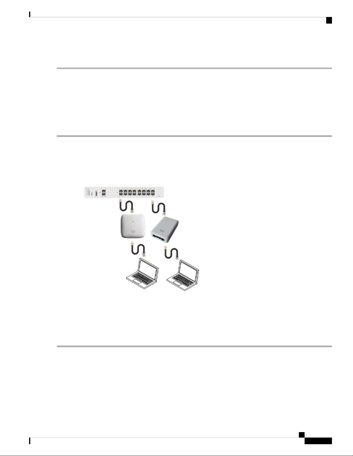
Wireless Settings
Enabling and Disabling WLANs RLANs
Enabling and Disabling WLANs RLANs
Step 1 Choose Wireless Settings > WLANs/RLANs.
Step 2 In the WLANs window, click the Edit icon adjacent to the WLAN you want to enable or disable.
Step 3 In the Edit WLAN/RLAN window, under General, select Enabled or Disabled to enable/disable WLAN/RLAN.
Step 4 Click Apply.
Note
Clicking Apply after creating a new WLAN or editing an existing one always enables the WLAN irrespective
of whether it was previously enabled or disabled.
Configuring RLAN in AP
In order to configure RLAN in Master capable APs (CBW240AC and CBW145AC), execute the following
steps to map the RLAN to your AP ports:
1. Create RLANs with 802.1x Authentication or Open access type
2. Create AP Groups, associate RLAN to AP Group, add APs to AP Group and finally associate Wired Ports
to RLANs.
To create RLAN, follow the procedure below:
Step 1 Navigate to Wireless Settings > WLANs and click Add new WLAN/RLAN.
Step 2 Under the General tab, select RLAN from the Type drop-down list box.
Step 3 Enter the Profile name.
Step 4 Under the RLAN Security, select 802.1x or Open for authentication type.
Step 5 When you enable the 802.1x, the following options are displayed:
Cisco Business Access Point Administration Guide, Version 10.0.1.0
47
Page 60

Wireless Settings
Editing and Deleting WLANs RLANs
a) MAB (MAC Authentication Bypass)—MAB enables port-based access control using the MAC address of the client.
A MAB-enabled port can be dynamically enabled or disabled based on the MAC address of the device that connects
to it. Add the client MAC in the Local MAC Address table. Refer to Blocking and Unblocking Clients, on page 49
clients. By default, it is enabled.
b) Authentication Server—Please refer to Security Type - WPA2 Enterprise.
Step 6 Use the parameters available on the General, RLAN Security, and Advanced tabs for configuring the remote LAN.
Note
Step 7 Click Apply to save the changes.
You can monitor the number of clients connected to the network by navigating to Monitoring > Network Summary
and view the wired clients in the Wired Networks block.
For descriptions of parameters available under RLAN Security, VLAN & Firewall, Traffic Shaping and
Advanced tabs, refer to Configuring WLAN Security, on page 38.
Editing and Deleting WLANs RLANs
Step 1 Choose Wireless Settings > WLANs/RLANs.
Step 2 In the table of WLANs listed, perform one of the following actions as required:
• To edit a WLAN/RLAN, click the Edit icon adjacent to the WLAN/RLAN you want to modify.
• To delete a WLAN/RLAN, click the Delete icon adjacent to the WLAN/RLAN you want to delete.
Viewing and Managing WLAN Users
You can view and manage WLAN users only for WPA2 Enterprise and Guest WLAN with Local User
Accounts as access types. To use your Cisco Business Wireless network, a wireless client should connect to
a WLAN in the network. To connect to a WLAN, the wireless client will have to use the user credentials set
for that WLAN. If this WLAN uses WPA2-Personal as a Security Policy, then the user must provide the
appropriate WPA2-PSK set for that WLAN on the Master AP. If the Security Policy is set to
WPA2-Enterprise/Local User Account, the user must provide a valid user identity and the corresponding
password
In the WLAN Users window, you can set up different users and their respective user credentials for the
different WLANs in the CBW AP wireless network. These are local users authenticated by the master AP
using WPA2-PSK.
To view and manage WLAN users, choose Wireless Settings > WLAN Users.
The WLAN Users window is displayed along with the total number of WLAN users configured on the Master
AP. It also lists all the WLAN users in the network along with the following details:
• User name—Name of the WLAN user.
• Guest user— Indicates a guest user account if the toggle button is enabled. This user account is provided
with a limited validity of 86400 seconds (or 24 hours) from the time of its creation.
Cisco Business Access Point Administration Guide, Version 10.0.1.0
48
Page 61

Wireless Settings
Blocking and Unblocking Clients
• WLAN Profile—The WLANs that the user can connect to.
• Password—The password to connect to a WLAN.
• Description—Additional details or comments about the user.
Adding a WLAN User
To add a WLAN user, click Add WLAN User and specify the following details:
• User name—Specify a name for the WLAN user account.
• Guest user—Enable the slider button if this is meant to be a guest WLAN user account. You can also
specify the validity of this account from the time of its creation, in seconds, in the Lifetime field. The
default value is 86400 seconds (that is, 24 hours). You can specify a lifetime value from 60 to 31536000
seconds (that is, 1 minute to 1 year).
• WLAN Profile—Select the WLAN that this user can connect to. From the drop-down list, choose a
particular WLAN, or choose Any WLAN to apply this account for all WLANs set up on the Master AP.
This drop-down list is populated with the WLANs which have been configured under Wireless Settings
> WLANs.
For information on adding WLANs, see Adding and Modifying a WLAN, on page 37.
• Password—The password to be used when connecting to a WLAN.
• Description—Additional details or comments for the user.
Editing a WLAN User
To edit a WLAN user, click the Edit icon adjacent to the WLAN user whose details you want to modify and
make the necessary changes.
Deleting a WLAN User
To delete a WLAN user, click the Delete icon adjacent to the WLAN user you want to delete. and then click
Ok in the confirmation dialog box.
Blocking and Unblocking Clients
Step 1 Go to Wireless Settings > WLAN Users > Local MAC Address.
Step 2 Click Add MAC Address and add the client MAC address.
Step 3 You can choose to whitelist/blacklist the client by selecting it in the Type option and then click Apply.
Choose the type as Blacklist to deny the client joining your network.
Note
Blacklisting a client or Mesh Extender that is currently joined to the network will not take effect until it attempts
to rejoin the network (after disconnect or reboot).
Choose the type as Whitelist to add the client. The MAC Filtering should be enabled on the WLAN to add your client
MAC to the Local MAC address with Type as Whitelist. This helps the client to join the network.
Cisco Business Access Point Administration Guide, Version 10.0.1.0
49
Page 62

Wireless Settings
Social Login for Guest Users
You can also import/export the Local MAC address list.
Social Login for Guest Users
This feature provides social login privileges for guest users that are connected using Google or Facebook
accounts. To enable this option, execute the following on the Master AP:
Step 1 On the left navigation pane, choose Wireless Settings > WLANs > Add new WLAN/RLAN
Step 2 Under the General tab, fill in the basic information for your WLAN. For details, see Adding and Modifying a WLAN,
on page 37.
Step 3 Click the WLAN Security tab. Specify the following details:
a) Enable the Guest Network toggle button.
b) Under Access Type drop down list, select Social Login.
c) Click Apply to save the configuration.
d) Once the WLAN is created with access type, Social Login, the Enable_Social_Login Pre-auth ACL is automatically
mapped to the WLAN.
e) The user can also add and edit their own URLs by navigating to Enable_Social_Login in Advanced > Security
settings.
f) The Guest WLAN with an enabled Social login access type will be created. Once the user connects to this guest
WLAN they will be redirected to Cisco default login page where they can find the login buttons for Google and
Facebook. The user can login using the Google/Facebook account and obtain the internet access.
Managing Associated Access Points
Step 1 Choose Wireless Settings > Access Points.
Step 2 In the Access Points Administration window, the number of APs associated with the CBW is displayed at the top of
the window, along with the following details:
• Manage—The following icons indicate whether the AP is acting as a Master AP or Master capable AP or Mesh
Extender.
Figure 1: Master AP icon
Figure 2: Mesh Extender icon
Cisco Business Access Point Administration Guide, Version 10.0.1.0
50
Page 63

Wireless Settings
Global AP Configuration
Figure 3: Subordinate AP icon
• Type—Specifies if the AP is Master capable or a Mesh Extender.
• Location—Location of the AP.
• Name—Name of the AP.
• IP Address—IP address of the AP.
• AP MAC—The MAC address of the AP.
• Up Time—Shows how long the AP has been associated to the Master AP.
• AP Model—The model number of the access point.
Note
When an AP joins an AP group; or the RF profile of the AP group is changed, the AP rejoins the Master AP.
The AP will receive new configuration specific to the new AP group or RF profile.
Global AP Configuration
This allows you to configure AP as 802.1x supplicant and Native VLAN ID.
Note
The AP can be configured as a 802.1x supplicant. This is authenticated by the switch against the ISE that is
using EAP-FAST, and EAP-TLS and PEAP. Once the port is configured for 802.1x authentication, the switch
does not allow any traffic other than 802.1x traffic to pass-through the port until the device connected to the
port authenticates successfully. An AP can be authenticated either before it joins the Master AP or after it has
joined an Master AP, in which case you can configure 802.1x on the switch after the Access Point joins the
Master AP.
Step 1 Navigate to Wireless Settings > Access Points.
Step 2 Click on the Global AP Configuration and configure the following parameters under the Credentials(802.1x) tab:
• 802.1x Authentication—Enable this option to configure the AP as an 802.1x supplicant.
• Username— Enter the user name for 802.1x authentication.
• Password—Enter the password for 802.1x authentication.
• Confirm Password—Re-enter the 802.1x password.
• EAP Method—Choose the method of 802.1x authentication.
Step 3 Configure Native VLAN ID under VLAN Tagging tab.
Cisco Business Access Point Administration Guide, Version 10.0.1.0
51
Page 64

Administering Access Points
Step 4 Click Apply.
Administering Access Points
Step 1 Choose Wireless Settings > Access Points.
Step 2 In the Access Points window, click the Edit icon adjacent to the AP you want to manage.
Wireless Settings
Note
You can only administer those APs that are associated to the Master AP.
Step 3 In the Edit, under the General tab, you can edit the following AP parameters:
• The Make me Master AP button is available only for subordinate APs that are capable of participating in the Master
Election process. Click this button, to make the AP, the Master AP.
• IP Configuration—Choose Obtain from DHCP to let the IP address of the AP be assigned by a DHCP server on
the network, or choose to have a Static IP address. If you choose to have a static IP address, then you can edit the
IP Address, Subnet Mask, and Gateway fields.
• AP Name—Edit the name of the AP. This is a free text field.
• Location—Edit a location for the AP. This is a free text field.
• Set as Preferred Master—Enable this to make the AP as the preferred Master.
The following non-editable AP parameters are also displayed under the General tab:
• Operating Mode—Displays the operating Mode of the AP.
• AP MAC address —Displays the AP MAC address.
• AP Model number —Displays the AP Model number.
• IP Address of the access point (non-editable only if Obtain from DHCP has been selected).
• Subnet mask (non-editable only if Obtain from DHCP has been selected).
• Gateway (non-editable only if Obtain from DHCP has been selected).
Step 4 For the master AP, under the Master tab, you can manually edit the following Master AP parameters:
• Master AP Name—You can edit the Master AP Name set during Initial configuration using Setup Wizard.
• IP configuration—You can configure either Static IP or obtain from DHCP.
• IP Address—This IP address decides the login URL to the Master AP's web interface. The URL is in the format
http://<ip addr> or https://<ip addr>. If you change this IP address, the login URL also changes.
• Subnet Mask—Subnet mask of the network.
Note
IP Address, Subnet Mask and Gateway fields are editable only if Static IP Address is selected.
• Country Code—Select the country for your Master AP. It is not advisable to change the country code unless you
have not configured the correct country in the initial setup wizard.
Cisco Business Access Point Administration Guide, Version 10.0.1.0
52
Page 65

Wireless Settings
Step 5 Under the Radio 1 and Radio 2 tabs you can set the following parameters.
Administering Access Points
Note
Channel
The Radio 1 tab corresponds to the 2.4 GHz (802.11 b/g/n) radio on all APs. The Radio 2 tab corresponds to
only the 5 GHz (802.11a/n/ac) radio on all APs.
The radio tab name also indicates the operational radio band within brackets.
DescriptionParameter
Enable or Disable the corresponding radio on the AP.Status
For 2.4 GHz, you can set this to Automatic,
or set a value from 1 to 11.
Selecting Automatic enables Dynamic
Channel Assignment. This means that
channels are dynamically assigned to each
AP, under the control of the master AP.
This prevents neighboring APs from
broadcasting over the same channel and
prevents interference and other
communication problems. For the 2.4 GHz
radio, 11 channels are offered in the U.S.
For 5 GHz, you can set this to Automatic, 36, 40,
44, 48, 52, 56, 60, 64, 100, 104, 108, 112, 116,
132, 136, 140, 149, 153, 157, 161, or 165.
For the 5 GHz radio, up to 23 non-overlapping
channels are offered.
Assigning a specific value statically assigns a
channel to that AP.
Note
The channels in both the radios will
change according to the country
configured in the Master AP.
and up to 14 in other parts of the world.
However, only 1-6-11 can be considered
non-overlapping if they are used by
neighboring APs.
Channel Width
Transmit Power
Interferer Detection
Assigning a specific value statically assigns
a channel to that AP.
The channel width for 2.4 GHz can only
be 20 MHz.
The channel width for 5 GHz can be set to
Automatic, or to 20, 40, or 80 MHz, if channel
bonding is used. By default, it is set to 80 MHz.
Channel bonding groups the channels by 2 or 4 for
a single radio stream. This increases the speed and
the throughput. Because the number of channels
is insufficient in 2.4 GHz, channel bonding cannot
be used to enable multiple non-overlapping
channels.
You can set it to Automatic, or provide a value ranging from 100, 75, 50, 25, 12 (in terms of
percentages).
By default, it is set to 100% (maximum power).
Selecting Automatic adjusts the radio transmitter output power based on the varying signal
level at the receiver. This allows the transmitter to operate at less than maximum power for
most of the time; when fading conditions occur, transmit power will be increased as required
until the maximum is reached.
Enable this option to identify the non Wi-Fi devices.
Note
Ensure that you enable the Interferer detection globally under Advanced > RF
Optimization (in Expert View).
Cisco Business Access Point Administration Guide, Version 10.0.1.0
53
Page 66

Access Point Groups
Step 6 Click Apply to save your changes and exit.
Wireless Settings
Note
For details on the Mesh tab, refer to Mesh Network Components, on page 58.
Access Point Groups
By creating Access Point Groups you can control which SSIDs or RLANs can be pushed to each AP group.
Each access point advertises the enabled WLANs/RLANs that belong to its access point group. The access
point does not advertise disabled WLANs/RLANs in its access point group or WLANs/RLANs that belong
to another group.
By default, there is a AP Group called default-group created on your master AP and all the WLANs/RLANs
are mapped to this default group. All the access points in the master AP also belong to this default-group.
This means, WLAN/RLAN (ID 1-16) will be available in any of the APs belonging to the default group.
To configure this, do the following:
1. Switch to Expert View by clicking the bi-directional icon on the top right of the Master AP UI.
2. Go to Wireless Settings > Access Points Groups > Add New Group.
3. In the General tab, provide an AP Group Name and a description for your reference.
4. In the WLANs tab, select the WLAN or RLAN that you want to push to the group.
5. In the Access Points tab, push the access point to the group that you created such that the WLANs/RLANs
is advertised in only those particular APs.
Note
RLANs are supported in non-mesh deployment only.
6. Select the RF profile in 2.4 GHz and 5 GHz, if needed. Else, you can create a custom RF Profile. For
details, refer to RF Profiles, on page 95.
7. In the Ports tab, enable the LAN ports to which you want to map the RLAN. Thereby, select a particular
RLAN from the Remote LAN drop-down list box. This is applicable only in non-mesh deployments.
By default, LAN1 and PoE is enabled.
Note
Power over Ethernet- PoE enables Power and Data to be combined onto a single Ethernet cable. For example,
IP cameras can be powered up through this port.
8. Click Apply.
Setting a Login Page for WLAN Guest Users
Before you begin, follow these steps to provide guest users with access to your network:
Cisco Business Access Point Administration Guide, Version 10.0.1.0
54
Page 67

Wireless Settings
Setting the Default Login Page
Step 1 Set up a new WLAN or decide on an existing WLAN, to which you will provide access for guest users. You can also
specifically set up a WLAN exclusively for guest access. This is done by setting the WLAN Security as Guest for that
WLAN. For more information, see Adding and Modifying a WLAN, on page 37.
Step 2 Set up a guest user account. Go to Wireless Settings > WLAN Users, and set up an account with the Guest User check
box selected. For more information, see Viewing and Managing WLAN Users, on page 48.
You can provide the Guest Users of your WLAN with one of the following login page options:
• A simple minimalist default login page with a few modification options. To configure this, see Setting the Default
Login Page, on page 55.
• A customized login page uploaded into the Master AP. To configure this, see Setting a Customized Login Page, on
page 56.
Setting the Default Login Page
Right out of the box, the default login page contains a Cisco logo and Cisco-specific text. You can choose to
modify this default login page as described here.
Step 1 Choose Wireless Settings > Guest WLAN.
Step 2 In the Guest WLANs page, the number of Guest WLANs currently set up in the network is displayed at the top of the
page.
Step 3 Choose the Internal (Default) login page in the Page Type drop-down list.
Step 4 Set the following parameters to modify the default internal login page:
• Display Cisco Logo—This field is set to Yes by default. To hide the Cisco logo that appears at the top-right corner
of the default window, choose No. However, you do not have an option to display any other logo.
Note
You can preview the changes by clicking Apply > Preview.
• Redirect URL After Login— To have guest users redirected to a particular URL (such as the URL for your company)
after login, enter the URL in this field. You can enter up to 254 characters.
• Page Headline—The default headline is Welcome to the Cisco Business Wireless. To create your own headline on
the login page, enter the desired text in this field. You can enter up to 127 characters.
• Page Message— The default message is displayed: Cisco is pleased to provide the Wireless LAN infrastructure for
your network. Please login and put your unified wireless solution to work.. To create your own message on the login
page, enter the desired text in this field, You can enter up to 2047 characters.
Step 5 Click Apply.
Cisco Business Access Point Administration Guide, Version 10.0.1.0
55
Page 68

Setting a Customized Login Page
Setting a Customized Login Page
You can create a custom login page on a computer, compress the page and image files into a .TAR file, and
then upload it to the Master AP. The upload is done via HTTP.
Note
When you save the Master AP's configuration, it does not include extra files or components, such as the web
authentication bundle, that you download and store on your Master AP. Hence, manually save external backup
copies of such files.
Note
Cisco TAC is not responsible for creating a custom web authentication bundle.
Before you begin
Create a custom login page on a computer while ensuring the following:
Wireless Settings
• Name the login page login.html. The Master AP prepares the web authentication URL based on this
name. If the server does not find this file after the web authentication bundle has been untarred, the bundle
is discarded, and an error message appears.
• The page should not contain more than 5 elements (including HTML, CSS, and Images). This is because
the internal Master AP web server implements a DoS protection mechanism that limits each client to
open a maximum of 5 (five) concurrent TCP connections depending on the load. Some browsers may
try to open more than 5 TCP sessions at the same time if the page contains more elements and this may
result in the page loading slowly depending on how the browser handles the DoS protection.
• Include input text boxes for the username and the password.
• Extract and set the action URL in the page from the original URL.
• Include scripts to decode the return status code.
• All paths used in the main page (to refer to images, for example) are of relative type.
• No filenames within the bundle are longer than 30 characters.
Compress the page and image files into a ,TAR file. The maximum allowed size of the files in their
uncompressed state is 1 MB.
Cisco recommends that you use an application that complies with GNUstandards to compress the .TAR file
(also referred to as the web authentication bundle.). If you load a web authentication bundle with a .TAR
compression application that is not GNU compliant, the Master AP will not be able to extract the files in the
bundle.
The .TAR file enters the Master AP’s file system as an untarred file.
Note
If you have a complex customized web authentication bundle which does not comply with the aforementioned
prerequisites, then Cisco recommends that you host it on an external web server.
Cisco Business Access Point Administration Guide, Version 10.0.1.0
56
Page 69

Wireless Settings
About Cisco Mesh
Step 1 Choose Wireless Settings > Guest WLAN.
The Guest WLANs page is displayed. The number of Guest WLANs currently set up in the network is displayed at the
top of the page.
Step 2 To upload a customized login page into the Master AP, in the Page Type drop-down list, choose Customized.
Step 3 Click Upload, to browse to and upload the .TAR file of the customized web authentication bundle.
Step 4 If you want the user to be directed to a particular URL (such as the URL for your company) after login, enter that URL
in the Redirect URL After Login text box. You can enter up to 254 characters.
Step 5 Click Apply.
Click Preview to view your customized web authentication login page.
About Cisco Mesh
Cisco Mesh introduces a new paradigm of wireless internet access by providing high data rate service and
reliability. It is also a solution to reduce the complexity of wiring between each devices in a network. For a
stable network establishment, there must be a wireless interacting medium between each APs.
CBW indoor mesh brings these values to you:
• Not having to run Ethernet wiring to each AP.
• Network connectivity where wires cannot provide connectivity.
• Easy to deploy and provide flexibility in deployment.
This chapter summarizes the design details for deploying a Cisco Mesh Extender for indoor environments.
The indoor wireless access takes advantage of the growing popularity of inexpensive Wi-Fi clients, enabling
new service opportunities and applications that improve user productivity and responsiveness.
Adding a Mesh Extender
For details refer to Adding Mesh Extenders, on page 15.
Convert Non-Mesh to Mesh Deployment
For maintaining, the mesh state between the AP’s there must be a communication establishment between
them and this takes place through the backhaul radio (2.4GHz or 5GHz – user configurable). To configure
the mesh mode in the Master AP, do the following:
Step 1 Go to Wireless Settings>Mesh.
Step 2 Enable the Mesh toggle button and click Apply.
Step 3 The entire network now functions in the Mesh mode after the Master AP reboots.
Step 4 Add the MAC address of the Mesh Extenders in the auth-list that you wish to join with the particular Master AP.
Note
For details refer, Adding Mesh Extenders, on page 15.
Cisco Business Access Point Administration Guide, Version 10.0.1.0
57
Page 70

Wireless Settings
Mesh Network Components
For the wired access points (CBW140AC, CBW240AC, CBW145AC) the MAC address will be added automatically in
the Local MAC Address table, provided they exist in the same network.
Step 5 The automatic entry of the physical address of the wired AP can be verified by knowing its last few digits in the MAC
address.
For example, when a CBW140AC has joined the Master AP, its MAC address will be displayed in the Local MAC
Address table with its corresponding description as (CBW140AC-f898). Here, f898 is the ending digits of its MAC
address A4:53:39:0E:F8:98.
Step 6 Wait for few minutes and navigate to Wireless Settings>Access Points.
Step 7 Check if the access point has joined the Master AP.
Mesh Network Components
Navigate to Wireless Settings > Access Points. Click Edit Access point. The following options are available
under the Mesh tab.
• AP Role—By default, the master AP role is set to Root and the mesh extenders role is set to Mesh. This
is only for user notification about the AP role. Not configurable.
• Bridge Type—By default, it is set as indoor
• Bridge Group Name—Bridge group names (BGNs) control the association of mesh access points. BGNs
can logically group radios to avoid two networks on the same channel from communicating with each
other. The setting is also useful if you have more than one master capable AP in your network in the
same sector (area). Default BGN is set with first 10 character of the configured SSID during initial setup
wizard. This option is available in Expert View.
Caution
Exercise caution when you configure a BGN on a live network. Always start a
BGN assignment from the farthest-most node (last node, bottom of mesh tree)
and move up toward the RAP to ensure that no mesh access points are dropped
due to old and new BGNs mixed within the same network.
• Strict Matching BGN—When Strict Match BGN is enabled on the mesh AP, it will scan ten times to
find the matched BGN parent. After ten scans, if the AP does not find the parent with matched BGN, it
will connect to the non-matched BGN and maintain the connection for 15 minutes. After 15 minutes,
the AP will again scan ten times and this cycle continues. The default BGN functionalities remain the
same when Strict Match BGN is enabled. By default, it is disabled. This option is available in Expert
View.
• Preferred Parent—This has to be computed from the Radio MAC of the Master capable AP which you
would like to set as preferred parent your Mesh AP. We need to add 11 in hex to last two bytes of the
Preferred Parent’s radio MAC. To obtain the Radio MAC of the Master capable AP, go to Monitoring
> Access Points, and the view the AP details by selecting the AP you want. Note down the Radio MAC
(xx:xx:xx:xx:xx:yy) and compute the value to be set in Preferred Parent field. Refer the table for sample
computation.
Cisco Business Access Point Administration Guide, Version 10.0.1.0
58
Page 71

Wireless Settings
Note
This field is present only in Mesh Extender's Mesh tab.
Mesh Network Components
After adding (+11) (yy')Before (yy)
3120
5140
7160
9180
B1A0
D1C0
F1E0
• Backhaul Interface—This displays the type of interface. It can be either 802.11a/n/ac if Mesh Backhaul
Slot is 5GHz and 802.11b/g, if Mesh Backhaul Slot is 2.4GHz.
• Install Mapping on Radio Backhaul—This option helps to broadcast the SSIDs in backhaul radio such
that the client can join the AP using the backhaul radio. By default it is Enabled. If you experience
Mesh performance or stability issues, you can disable this option to avoid wireless clients joining the
backhaul radio.
• Mesh Backhaul Slot—The communication between each APs are carried over a particular radio and
you can configure it in either 5GHz or 2.4GHz. By default, it is in 5GHz mode.
Note
The Backhaul interface configuration done under Wireless Settings > Mesh >
Mesh Backhaul Slot is the global configuration. If you want to override it for
selected Access Points, you can change the Backhaul interface configuration by
navigating to Wireless Settings > Access Points (Edit) > Mesh > Mesh Backhaul
Slot.
• Ethernet Bridging—By using this feature, you can access internet by connecting a wired client to the
LAN ports of the APs in the Mesh network. By default, it is Enabled.
Master APs (CBW240AC, CBW145AC) and Mesh Extender (CBW141AC or CBW143AC with PoE
adapter module) support the Ethernet Bridging functionality.
Refer LAN port functionality for different models, on page 107 to know the LAN port functionalities for
different model APs.
Ethernet bridging is enabled by default in Mesh mode.
1. Connect a client to the Ethernet port of CBW240AC or CBW145AC or CBW141ACM or
CBW143ACM.
Cisco Business Access Point Administration Guide, Version 10.0.1.0
59
Page 72

Changing Mesh Parameters
Wireless Settings
Note
The wired client connected to the LAN port of the AP will obtain the IP address
in the AP’s VLAN network.
2. Check if you are able to access the internet.
Note
The Master AP Web UI can be accessed only through the Management IP and
not through the URL: https://ciscobusiness.cisco.
3. In the Mesh mode, the wired client connected to LAN ports will not be displayed in the Master AP
UI.
4. On connecting a client to the Ethernet port, the Operational Status changes to UP. You can change
the VLAN and mode of that LAN port using the following steps. (By Default the Mode is Access).
To configure VLANs, enable VLAN Transparency in Mesh Tab under Wireless Settings > Mesh
> VLAN Transparent. Click on the Edit icon to change the configuration of the particular port.
The VLAN Mapping window is displayed:
a. Set the Mode to Access or Trunk.
b. When you select the mode as Access, the VLAN Id is 0 by default. This enables the Wired client
to obtain the IP in AP’s VLAN.
c. When you select the mode as Trunk, you can configure the Native VLAN on that port and other
allowable VLANs for incoming or outgoing traffic.
Note
You can configure the Native VLAN under Wireless Settings > Access Points
> Global AP Configuration > VLAN Tagging.
Changing Mesh Parameters
Following are the several mesh configurations that are available in the Master AP UI under Wireless Settings
> Mesh.
Backhaul Client Access
When Backhaul Client Access is enabled, it allows wireless client association over the backhaul radio. The
backhaul radio is a 5-GHz radio for most of the Cisco Access Points. This means that a backhaul radio can
carry both backhaul traffic and client traffic.
When Backhaul Client Access is disabled, only backhaul traffic is sent over the backhaul radio and client
association is over the second radio(s). By default, this option is Enabled.
Cisco Business Access Point Administration Guide, Version 10.0.1.0
60
Page 73

Wireless Settings
Mesh Backhaul Radio Resource Management
The Radio Resource Management (RRM) software embedded in the Master AP acts as a built-in RF engineer
to consistently provide real-time RF management of your wireless network. RRM enables the Master AP to
continually monitor their associated lightweight access points for information on traffic load, interference,
noise, coverage and other nearby APs.
The RRM measurement in the mesh AP backhaul is enabled, if the wired Root AP has Ethernet uplink and
there is no Mesh Extender joined to it.
Mesh Backhaul Slot
Note
The Backhaul interface configuration done under Wireless Settings > Mesh > Mesh Backhaul Slot is the
global configuration. If you want to override it for selected Access Points, you can change the Backhaul
interface configuration by navigating to Wireless Settings > Access Points > (Edit) > Mesh > Mesh Backhaul
Slot.
In certain countries, Mesh Network with 5 GHz backhaul network is not allowed to use. Even in countries
which is permitted with 5 GHz, customers may prefer to use 2.4 GHz radio frequencies to achieve much larger
Mesh or Bridge distances.
Mesh Backhaul Radio Resource Management
When a Master AP downlink backhaul is changed from 5 to 2.4 GHz or from 2.4GHz to 5 GHz, that selection
gets propagated from Master AP to all the Subordinate APs and they will disconnect from the previously
configured channel to get reconnected to another channel. To do this, follow the instructions below:
Step 1 Go to Wireless Settings>Mesh>Mesh Backhaul Slot.
Step 2 Select the backhaul radio (either 5 GHz or 2.4GHz) in the master AP such that the configuration gets pushed to its
subordinate APs to have a better mesh coverage.
Note
Only Master capable APs are configured with the backhaul frequency of 5 or 2.4GHz. Once the AP is configured,
the same frequency selection will propagate down the branch to all the Subordinate APs.
Modifying AP Port Configuration to Access/Trunk Mode
Step 1 Go to Wireless Settings > Access Points.
Step 2 Click Edit AP.
Step 3 In the Mesh tab, ensure that the Ethernet Bridging is enabled.
Step 4 Click Edit in the Port table. This is available when Ethernet Bridging is enabled.
Step 5 In the Mode tab, select Access or Trunk.
Step 6 In the VLAN Id, specify the VLAN.
The Operational Status changes to UP when an ethernet port is connected to a client.
Cisco Business Access Point Administration Guide, Version 10.0.1.0
61
Page 74

VLAN Transparent
VLAN Transparent
Note
Wireless Settings
This feature determines how a mesh access point handles VLAN tags for Ethernet bridged traffic. If VLAN
Transparent is enabled, then VLAN tags are not handled and packets are bridged as untagged packets. To
configure, go to Wireless Settings > Mesh > Ethernet Bridging.
No configuration of Ethernet ports is required when VLAN transparent is enabled. The Ethernet port passes
both tagged and untagged frames without interpreting the frames.
If VLAN Transparent is disabled, then all packets are handled according to the VLAN configuration on the
port (trunk, access mode). For details, see Modifying AP Port Configuration to Access/Trunk Mode, on page
61.
Note
• If the Ethernet port is set to Trunk mode, then Ethernet VLAN tagging must be configured.
• To use VLAN tagging, you must uncheck the VLAN Transparent check box. By default, it is enabled.
To enable the VLAN Transparent, do the following:
Step 1 Navigate to Wireless Settings>Mesh>Ethernet bridging.
Step 2 Enable VLAN Transparent.
Cisco Business Access Point Administration Guide, Version 10.0.1.0
62
Page 75

CHAPTER 6
Management
This chapter describes how to manage the network and upgrade the software. It contains the following topics:
• About Management Access Interface, on page 63
• Setting Up Management Access Interface, on page 63
• Limitation of Web Based Management Sessions, on page 64
• Managing User Priority Order, on page 64
• Managing Admin Accounts, on page 65
• Managing Guest Users using the Lobby Admin account, on page 67
• Managing TACACS+ and RADIUS Servers, on page 68
• Setting Date and Time, on page 71
• Configuring Date and Time Manually, on page 72
• Updating the CBW AP Software, on page 73
• Updating the Software using HTTP, on page 75
• Updating the Software using TFTP, on page 76
• Updating the Software using SFTP, on page 77
• Updating the Software through Cisco.com, on page 78
About Management Access Interface
The Management Access Interface is the default interface for in-band management of the Master AP and
connectivity to enterprise services. It is also used for communication between the Master AP and connected
access points (APs). The management interface has the consistently pingable in-band interface IP address on
the Master AP. You can access the web interface of the Master AP by entering the management interface IP
address of the Master AP or using https://ciscobusiness.cisco in your browser's address bar.
For APs, the Master AP requires one management interface to control all communications and one AP manager
interface to control all Master AP-to-access point communications, regardless of the number of ports.
Setting Up Management Access Interface
To enable or disable the different types of management access to the Master AP, do the following:
Step 1 Choose Management > Access.
Cisco Business Access Point Administration Guide, Version 10.0.1.0
63
Page 76

Management
Limitation of Web Based Management Sessions
The Access window is displayed. The number of enabled management types are displayed at the top of the window.
Step 2 You can enable or disable the following types of management access to the Master AP, by toggling the switch buttons.
• HTTP Access—This enables the HTTP access mode, which allows you to access the Master AP GUI using
http://<ip-address> or http://ciscobusiness.cisco through a web browser. By default, the HTTP access is disabled.
Note
• HTTPs Access—A secure access for Master AP UI, using https://<ip-address> or https://ciscobusiness.cisco. The
default value is Enabled.
• HTTP-HTTPS Maximum Session—To set the maximum number of web sessions (HTTP/HTTPS). It can range
between 1-15. By default, you can support upto 15 sessions.
• SSHv2 Access—Enable Secure Shell Version 2 (SSHv2) access mode for Master AP console, that uses data encryption
and a secure channel for data transfer. The default value is Disabled.
Note
Step 3 WebAuth SecureWeb—Enable web based authentication for Guest WLAN inorder to access or visit the Guest
authentication page over HTTPS.
Step 4 Click Apply to save your changes.
HTTP access mode is not a secure connection.
By default, SSH is disabled for all APs that are connected to the CBW network. SSH can be enabled only
by TAC for debugging purposes.
Limitation of Web Based Management Sessions
This feature helps to provision the number of sessions supported for the Master AP UI. It is implemented by
limiting the number of UI management sessions based on the number of HTTP/HTTPS sessions configured
by the user.
• Choose Management > Access. Under HTTP-HTTPS Maximum Sessions field set the number of
allowed sessions. Configurable value is from 1-15.
• Click Apply to save the changes. On configuring try to access the web sessions from the client using
management IP.
• If the number of users exceeds the configured value, the session access is restricted and prompts for a
reload of session.
Managing User Priority Order
When multiple databases are configured, it is important to configure the admin account user priority. To
configure the priority,do the following:
Step 1 Enable Expert View on the Master AP UI. To switch to expert view, click the bidirectional arrow icon on the top right
of the home screen.
Step 2 Navigate to Management > Admin Accounts and click on the Management User Priority Order. By default, the local
database is always queried first. If the username is not found, the master AP switches to the RADIUS server if configured
Cisco Business Access Point Administration Guide, Version 10.0.1.0
64
Page 77

Management
Managing Admin Accounts
for RADIUS or to the TACACS+ server if configured for TACACS+. The default priority setting is in the order of Local
Admin Accounts and then RADIUS.
Step 3 To change the priority, between TACACS+ and RADIUS, click on the drag icon and move UP or DOWN.
Local Admin Accounts cannot be moved to Priority 3. It can be in the order of either 1 or 2 only.
Step 4 Click Apply to save the changes.
Managing Admin Accounts
You can manage the Cisco Business Wireless AP network through the Master AP UI based on the privileges
assigned to your user account. This prevents unauthorized users from accessing or configuring the Master
Ap.
You can log in to the Master AP UI using an admin account having one of the following access types:
• Read/Write—This administrative account has complete access to view and modify the Master AP
configuration.
• Read Only—This limited access administrative account allows the user to only view the Master AP
configuration. This user is restricted from making any changes to the configuration.
• Lobby Ambassador—This restricted administrative account allows the user to only create and manage
guest user accounts. The lobby ambassador can also print or email the guest user account credentials.
For information about creating guest user accounts, see Creating a Guest User Account, on page 67.
Adding an Admin Account
Step 1 Choose Management > Admin Accounts.
The total count of admin accounts on the Master AP is displayed at the top of this window while the table provides a
detailed listing of all the available admin accounts.
Step 2 In the Admin Accounts window, click Add New User to add a new admin user.
Step 3 In the Add/Edit Local admin account window, set the following parameters as required:
• Username—The login user name used by the administrative user. User name must be unique. You can enter up to
24 ASCII characters.
Note
• Access—Set one of the following access privileges for the administrator:
User names are case sensitive.
• Read Only
• Read/Write
• Lobby Ambassador
Cisco Business Access Point Administration Guide, Version 10.0.1.0
65
Page 78

Management
Editing an Admin Account
• Password—The password is case sensitive and can contain 8-127 ASCII characters. When specifying a password,
ensure the following:
• The password must include lowercase letters, uppercase letters, digits, and special characters. The special
characters can be ~, !, @, #, $, %, ^, &, *.
• No character in the password can be repeated more than three times consecutively.
• The new password cannot be the same as the associated username or the username reversed.
• The password cannot be cisco, ocsic, or any variant obtained by changing the capitalization of the letters in the
word Cisco. In addition, you cannot substitute 1, I, or ! for i, 0 for o, or $ for s.
Step 4 Re-enter the same password in Confirm Password.
Step 5 Enable Show Password to view the password entered.
Step 6 Password Expiry—This option facilitates to expire password for admin accounts. By default, the password expiry is
disabled and the expiry value is set to 0 (The Admin Account will remain constant until deleted). If the password expiry
is enabled, then the value is set to 180 days by default. You can set the value ranging from 1 - 180 days.
Note
Step 7 Click Update to save your changes.
If the Master AP UI is logged in with an admin account that has the password expiry enabled, a reminder
message will pop-up when you log in. This message will start popping up only when there are 7 days left for
password expiry.
Once the expiry value is exceeded, the admin account will be deleted.
Editing an Admin Account
Step 1 Choose Management > Admin Accounts.
The Admin Accounts page is displayed, along with the list of all the admin accounts present on the Master AP. The total
count of admin accounts on the Master AP is displayed at the top of the page.
Step 2 Click the Edit icon adjacent to the account you want to edit.
Step 3 Modify the admin account parameters, as required. For descriptions of these parameters, see Adding an Admin Account,
on page 65.
Step 4 Click Update to modify the parameters.
Deleting an Admin Account
Step 1 Choose Management > Admin Accounts.
The Admin Accounts window is displayed, along with the list of all the admin accounts present on the Master AP. The
total count of admin accounts on the Master AP is displayed at the top of the page.
Cisco Business Access Point Administration Guide, Version 10.0.1.0
66
Page 79

Management
Managing Guest Users using the Lobby Admin account
Step 2 Click the Delete icon adjacent to the account you want to delete.
Step 3 Click Ok in the confirmation dialog box.
Managing Guest Users using the Lobby Admin account
Guest user accounts are created to allow temporary access to the network. This network access is granted after
successful authentication of the guest account credentials.
You can create and manage guest user accounts using the lobby ambassador admin account. To know more
about lobby ambassador accounts, see Managing Admin Accounts, on page 65.
Creating a Guest User Account
Before you begin
You will need at least one lobby ambassador user account and one Guest WLAN with Local User Account
or RADIUS Access Type, before you create a guest user account. For information about creating a lobby
ambassador account, see Adding an Admin Account, on page 65.
Step 1 In your browser, navigate to the Master AP UI.
Step 2 Login using valid Lobby Ambassador credentials.
Step 3 In the Lobby Ambassador Guest Management window, click Add Guest User.
Step 4 Enter the following details for the guest user account:
• User Name—Specify an user name for the guest user account.
• Wireless Network—Select the desired guest WLANs that have already been configured for guest access to the
network.
Note
• Permanent User—Select this check box to allow the guest user account access to the network without time restriction.
• Expiry Date & Time—Specify the date and time by clicking the calendar and clock icons respectively. The guest
user account gets disabled at the specified date and time preventing access to the guest network.
Note
• Generate Password—Click this radio button to automatically generate a password for the guest user account being
created.
If you prefer to manually specify a password for the guest user account, enter it in the Password and Confirm
Password fields.
• Password— Specify a password for the guest user account.
• Confirm Password—Ensure that this entry matches what you have typed in the Password field.
• Description—This field is optional. The user can specify a suitable description for the guest user account.
To know more about creating a guest WLAN, see Creating a Guest Network, on page 111.
If the Permanent User check box is selected, then this field disappears from the dialog box.
Step 5 Click Update.
Cisco Business Access Point Administration Guide, Version 10.0.1.0
67
Page 80

Managing TACACS+ and RADIUS Servers
You can choose to share the account credentials with the guest user either via email or by printing it out.
Management
Note
You can also modify or delete the Guest User account by using the Edit/Delete icons.
You can also modify or delete the Guest User account by using the Edit/Delete icons.
Username and password are case sensitive.
Managing TACACS+ and RADIUS Servers
Master AP supports up to Six RADIUS and Three TACACS Servers. To configure RADIUS and TACACS+
Servers, enable Expert View on the Master AP UI by clicking the bidirectional arrow icon on the top right
of the home screen.
Adding TACACS+ Servers
Step 1 Navigate to Management > Admin Accounts.
Step 2 To add TACACS+ servers, click TACACS+ tab.
Step 3 Click Add TACACS+ Authentication Server button and enter the following:
Note
For adding TACACS+ Accounting Server, choose Add TACACS+ Accounting Server and proceed with the
following instructions
• Server Index—Select 1 through 3
• State—Enable the state. By default this is Enabled
• Server IP Address—Enter the IPv4 address of the TACACS+ server
• Shared Secret—Enter the shared secret
• Port Number—Enter the port number being used for communicating with the TACACS+ server. By default, the
port number is 49.
• Server Timeout—Enter the server timeout. By default, the timeout is 5 seconds.
The Table displays the configured TACACS+ (authenticating, authorizing, accounting) servers.
You can also modify or delete TACACS+ servers by using the Edit/Delete icons.
Configuring RADIUS Servers
Step 1 Navigate to Management > Admin Accounts.
Step 2 To add the RADIUS servers, click RADIUS and enter data as specified in the following steps:
Cisco Business Access Point Administration Guide, Version 10.0.1.0
68
Page 81

Management
Configuring RADIUS Servers
Step 3 Authentication Call Station ID Type—From the drop-down list, choose the option that is sent to the RADIUS server
in the Access-Request message. One of the following format types can be chosen as the Authentication Call Station
ID Type that is sent to the RADIUS server:
• IP Address
• Master AP MAC Address
• AP MAC Address
• AP MAC Address:SSID
• AP Name:SSID
• AP Name
• AP Group
• Flex Group
• AP Location
• VLAN ID
• AP Ethernet MAC Address
• AP Ethernet MAC Address: SSID
• AP Label Address
• AP Label Address: SSID
• AP MAC:SSID AP Group
• AP Eth MAC:SSID AP Group
Step 4 Authentication MAC Delimiter—From the drop-down list, choose the option that is sent to the RADIUS server in
the Access-Request message. The delimiters can be one of the following:
• Colon
• Hyphen
• Single-hyphen
• No Delimiter
Step 5 Accounting Call Station ID Type—From the drop-down list, choose the option that is sent to the RADIUS server in
the Access-Request message. One of the following format types can be chosen as the Accounting Call Station ID Type
that is sent to the RADIUS server:
• IP Address
• Master AP MAC Address
• AP MAC Address
• AP MAC Address:SSID
• AP Name:SSID
• AP Name
• AP Group
• Flex Group
• AP Location
• VLAN ID
• AP Ethernet MAC Address
• AP Ethernet MAC Address: SSID
• AP Label Address
• AP Label Address: SSID
• AP MAC:SSID AP Group
• AP Eth MAC:SSID AP Group
Cisco Business Access Point Administration Guide, Version 10.0.1.0
69
Page 82

Management
Adding RADIUS Servers
Step 6 Accounting MAC Delimiter—From the drop-down list, choose the option that is sent to the RADIUS server in the
Access-Request message. The delimiters can be one of the following:
• Colon
• Hyphen
• Single-hyphen
• No Delimiter
Step 7 Fallback Mode—Specify the RADIUS server fallback behavior from the drop-down list. It can be one of the following:
• Off—Disables RADIUS server fallback.
• Passive—Causes the master AP to revert to a server with a lower priority from the available backup servers without
using extraneous probe messages. The master AP ignores all inactive servers for a time period and retries later
when a RADIUS message needs to be sent.
• Active—Causes the master AP to revert to a server with a lower priority from the available backup servers by
using RADIUS probe messages to proactively determine whether a server that has been marked inactive is back
online. The master AP ignores all inactive servers for all active RADIUS requests. Once the primary server receives
a response from the recovered ACS server, the active fallback RADIUS server no longer sends probe messages
to the server requesting the active probe authentication.
Step 8 Username—If you enabled Active fallback mode, enter the name to be sent in the inactive server probes in the Username
field. You can enter up to 16 alphanumeric characters. The default value is cisco-probe.
Step 9 Interval—If you enabled Active fallback mode, enter the probe interval value (in seconds) in the Interval text box.
The interval serves as inactive time in passive mode and probe interval in active mode. The valid range is 180 to 3600
seconds, and the default value is 300 seconds.
Step 10 AP Events Accounting—Enable this toggle button to activate sending of accounting requests to RADIUS server.
During network issues, the APs join/disjoin from the master AP. Enabling this option ensures that these events are
monitored and the accounting requests are sent to the RADIUS server to help you detect the network issues.
Step 11 Click Apply to save the changes.
Adding RADIUS Servers
Step 1 Navigate to Management > Admin Accounts.
Step 2 To add the RADIUS servers, click RADIUS.
This page lists any RADIUS servers that have already been added. Choose to add one of the following:
• Add RADIUS Authentication Server
• Add RADIUS Accounting Server
Note
The pages used to add authentication and accounting servers contain similar fields. The following instructions
are detailed for Add RADIUS Authentication Server pages. You would follow the same steps for Add
RADIUS Accounting Server page.
• You can also modify or delete the Radius servers by using the Edit/Delete icons.
Step 3 Click Add RADIUS Authentication Server and enter the following:
Cisco Business Access Point Administration Guide, Version 10.0.1.0
70
Page 83

Management
• Server Index—Select 1 through 6
• State—Enable the state. By default this is Enabled.
• Server IP Address—Enter the IPv4 address of the RADIUS server
• Shared Secret—Enter the shared secret
• Port Number—Enter the port number used for communicating with the RADIUS server. By default, the port number
of Authentication server is 1812, and the Accounting server is 1813.
• Server Timeout—Enter the server timeout. By default, the timeout is 5 seconds.
Setting Date and Time
The date and time on the Cisco Business Wireless Master AP is first set when running the initial configuration
setup wizard. You can enter the date and time manually or you can specify a Network Time Protocol (NTP)
server that sets the time and date.
Setting Date and Time
Using NTP Servers to Automatically Set the Date and Time
You can have up to three Network Time Protocol (NTP) servers, to which the Master AP can automatically
sync to set the date and time.
By default three NTP servers are automatically created. The default fully qualified domain names (FQDN)
of the NTP servers are:
• 0.ciscome.pool.ntp.org, with NTP Index value 1.
• 1.ciscome.pool.ntp.org, with NTP Index value 2.
• 2.ciscome.pool.ntp.org, with NTP Index value 3.
For adding and editing NTP server details, go to Management > Time. This opens the Time Settings page.
Adding and Editing NTP Servers
You can have up to three Network Time Protocol (NTP) servers, using which the Master AP can automatically
set the date and time.
Step 1 Choose Management > Time.
The Time Settings window is displayed, with the set time zone shown at the top of the page. The current date and time
are displayed in the Set Time Manually field. Existing NTP servers, if any, are listed in the order of their NTP Index
values.
Step 2 In the NTP Polling Interval field, specify the polling interval, in seconds.
Step 3 To edit an existing NTP server, click its adjacent Edit icon. To add a new NTP server, click Add NTP Server.
Step 4 You can add or edit the following values for an NTP server:
Cisco Business Access Point Administration Guide, Version 10.0.1.0
71
Page 84

Refreshing NTP Server Status
a) NTP Index—Specify an NTP Index value to set the priority of the NTP server. NTP Index values can be set from 1
to 3, in the order of decreasing priority. The Master AP will try and sync with the NTP server with the highest priority
first, until the specified polling interval time runs out. If the sync is successful, the Master AP does not continue
trying to sync with any of the remaining NTP servers. If the sync is unsuccessful, then the Master AP will try to sync
with the next NTP server.
b) NTP Server—Specify the IPv4 address or the fully qualified domain name (FQDN) for the NTP server. When you
specify an FQDN, a DNS lookup is done. If the lookup fails, an error will be logged in the Syslog server. The Master
AP will continue to resolve this FQDN and errors will be logged until you change the NTP configuration or specify
a valid FQDN.
Step 5 Click Apply.
Refreshing NTP Server Status
The NTP server table on the Time Settings page, displays the status of the connection to each NTP server in
the NTP Status column. The status may be one of the following:
• Not Tried—A sync has not been attempted yet.
Management
• In Sync—The Master AP time is in sync with the NTP server.
• Not Synched—The Master AP time is not in sync with the NTP server.
• In Progress—A sync is being attempted.
Click Refresh at any time to see the updated NTP status.
Deleting and Disabling NTP Servers
To delete an NTP server, choose Management > Time. In the Time Settings page, click the Delete icon
adjacent to the NTP server you want to delete. Click OK in the confirmation dialog, and then click Apply.
To disable the option of setting up the date and time using NTP servers, you will need to delete all configured
NTP servers by following the above process.
Configuring Date and Time Manually
Step 1 Choose Management > Time.
The Time Settings window is displayed, with the set time zone shown at the top of the page. The current date and time
are displayed in the Set Time Manually field.
Step 2 From the Time Zone drop-down list, choose your local time zone.
When you choose a time zone that uses Daylight Saving Time (DST), the automatically sets its system clock to reflect
the time change when DST occurs. In the U.S., DST starts on the second Sunday in March and ends on the first Sunday
in November.
Step 3 Select the Set Time Automatically from Current Location check box to set the time based on the time zone specified.
Step 4 In the Set Time Manually field:
Cisco Business Access Point Administration Guide, Version 10.0.1.0
72
Page 85

Management
• Click the calendar icon and choose the month, day, and year.
• Click the clock icon and specify the time, in hour and minutes.
Step 5 Click Apply.
Updating the CBW AP Software
Note
Refer to Image Update Prerequisite for updating a device later in this section.
To view the current software version of your Master AP, you can choose the one of the following methods:
• Click the gear icon at the top-right corner of the web interface, and then click Master AP Information.
Updating the CBW AP Software
• Choose Management > Software Update. The Software Update window is displayed with the current
software version number listed on the top.
You can update the CBW AP software using the Master AP's web interface. Current configurations on the
Master AP will not be deleted.
The following are the software update methods:
• Updating the Software using HTTP
• Updating the Software using TFTP
• Updating the Software using SFTP
• Updating the Software through Cisco.com
A software update ensures that both the Master AP software and the software on all the associated Subordinate
APs are updated. Newly joining APs will be upgraded to the current version of the software running on the
Master AP.
The software download happens in the background, without impacting the network. The upgrades are
automatically sequenced to ensure that the network performance is not impacted by software update.
Note
The software of up to three access points can be concurrently updated.
Image Update Prerequisite
Before updating the CBW APs, you are required to obtain the Master AP firmware image and the Mesh
Extender (if your network has any Mesh Extenders) firmware image using the following steps:
• Browse to the Cisco Download Software page: http://www.cisco.com/cisco/software/navigator.html
Cisco Business Access Point Administration Guide, Version 10.0.1.0
73
Page 86

Updating the CBW AP Software
• From the Download Software window, browse to Wireless > Access Points. Based on your AP model,
• Choose a software release number.
• Click Download corresponding to the CBW-Bundle-10-x-x-0.zip file.
• Read the Cisco’s End User Software License Agreement and then click Agree to proceed.
• Save the ZIP file to your computer's hard drive, and then extract the contents to a directory on your
Management
browse to Cisco Business 100 Series Access Points/Cisco Business 200 Series Access Points to view a
list of currently available software, with the latest displayed on the top.
computer.
CBW AP Series
Image SizeSoftware File to
be Chosen
~60MBap1g5CBW140AC, CBW145AC, CBW240AC (Master capable APs)
~35MBap1g5-capwapCBW141ACM, CBW142ACM, CBW143ACM (Mesh Extenders)
Pre-download Image Status
You can monitor the status and progress of the update via HTTP/TFTP/SFTP/cisco.com on the Software
Update page. The following data is displayed as the update progresses:
• Total number of APs in the network.
• Number of APs that are currently being updated, waiting to be updated, being rebooted and those that
failed to update.
In addition to the above summary, each AP update progress is also shown using the following data:
• AP Name—The AP name
• AP Type —Displays if the AP is a Master AP or Master Capable AP or Mesh Extender
• AP Location—The AP location
• Download Percentage— By default it displays NA. While pre-downloading the software, the percentage
of download is displayed.
• Last Update Error—In case of any error, during pre-download, the error is displayed here
• State—Status of the pre-image download to the Mesh Extenders in the network. It can be one of the
following:
• None
• Initiated
• Pre-downloading
• Completed
• Retry Attempts—Number of Attempts re-tried.
Cisco Business Access Point Administration Guide, Version 10.0.1.0
74
Page 87

Management
Updating the Software using HTTP
Updating the Software using HTTP
Step 1 Obtain the ZIP file and extract the Master AP software image and Mesh Extender (if your network has any Mesh
Extenders) firmware image.
Step 2 From the Master AP web interface, choose Management > Software Update.
The Software Update window with the current software version number is displayed.
Step 3 In the Transfer Mode drop-down list, choose HTTP.
Note
Important
For Mesh deployments, you must upgrade the Mesh Extender image prior to the Master AP image upgrade.
Proceed with Step 4-7 if you have Mesh Extenders in the CBW AP network.
Step 4 Enable Mesh Extender Image option to load the Mesh Extender image (ap1g5-capwap). By default, this option will
be disabled.
Step 5 Click the Browse button adjacent to the Mesh Image File field, navigate to the folder having the unpacked ZIP file
contents, and choose ap1g5-capwap software file.
Note
The file explorer that opens here is an operating system-specific explorer depending on the OS of your
computer.
Step 6 Click Update, and then click Ok in the confirmation dialog.
Caution
The top section of the page indicates the status of the download. Do not manually power down or reset the
Master AP or any AP during this process.
The Pre-Download Image Status section displays the status of the pre-image download to the Mesh Extenders in the
network.
You can abort a software update that is in progress, at any time before the Master AP completes rebooting, by clicking
Abort.
Step 7 One Mesh Extender in the network gets the image first and shares the image to other Mesh Extenders. Once all the
Mesh Extenders in the network are pre-downloaded or moved to Complete status, Disable the Mesh Extender Image
option.
Step 8 Now, update the Master AP and other Master capable APs in the network. To do so, click Browse adjacent to the File
field. Navigate to the folder having the unpacked ZIP file contents, and choose the ap1g5 software file.
Step 9 Check the Auto Restart check box for the Master AP and Mesh Extender to reboot automatically after the image
pre-download is complete for all the APs.
Step 10 Click Update and then click Ok in the confirmation dialog.
The status of the download is displayed on top of the page.
Step 11 One Master AP in the network obtains the image and shares the image to all other Master capable APs.
Step 12 After all the APs’ state is moved to Complete, the Master AP restarts (or reboots) to complete the software upgrade.
If you have not checked the Auto Restart check box, you can manually reboot the Master AP, after the upgrade, by
choosing Advanced > Master AP Tools, and clicking Restart Master AP.
Step 13 Log in to the Master AP UI (after clearing the cache) and verify the Master AP software version in the Software Update
window.
Cisco Business Access Point Administration Guide, Version 10.0.1.0
75
Page 88

Updating the Software using TFTP
Management
Note
• While adding the Mesh Extender to the existing Mesh deployment, the new Mesh Extender will obtain
the image from the existing connected Mesh Extender. This ensures efficient upgrade.
• The newly joining Mesh Extender will get the image from Cisco.com or TFTP server, if there is no other
Mesh Extender in the network. Please configure Transfer Type to be Cisco.com/TFTP to allow the
new join Mesh Extender obtain the image and join the CBW network.
Updating the Software using TFTP
Before you begin
• Prepare a TFTP server to host the CBW AP software file using the following guidelines:
• Ensure that the TFTP server supports extended TFTP for file sizes greater than 32 MB. Some TFTP
servers that support files of this size are tftpd32.
• If you attempt to download the Master AP software and your TFTP server does not support the file
size, an error message is displayed: TFTP failure while storing in flash
• A computer that can access Cisco.com and the TFTP server will be required.
Note
Ensure that the TFTP server has the latest software bundle on Cisco.com
Step 1 Obtain the ZIP file and extract the Master AP software image and Mesh Extender (if your network has any Mesh
Extenders) firmware image. Copy the folder to the default directory on your TFTP server.
Step 2 From the Master AP UI, choose Management > Software Update.
The Software Update window with the current software version number is displayed.
Step 3 In the Transfer Mode drop-down list, choose TFTP.
Step 4 In the IP Address (IPv4) field, enter the IP address of the TFTP server.
Step 5 In the File Path field, enter the TFTP server directory path of the software file.
Step 6 To set the Master AP to automatically reboot after the image pre-download is complete, check the Auto Restart check
box.
You can also manually reboot the Master AP after the upgrade. Choose Advanced > Master AP Tools and click
Restart Master AP.
Step 7 Click Save to save the parameters that you have specified.
These parameters (IP address and File Path of the TFTP server) will remain saved unless you specifically change them
in future. You do not have to re-enter these parameters during the next software update.
Step 8 You can perform the update right away or schedule it for a later time.
• To proceed with the update right away, click Update, and then click Ok in the confirmation dialog.
Cisco Business Access Point Administration Guide, Version 10.0.1.0
76
Page 89

Management
Updating the Software using SFTP
• To perform the update later, up to a maximum of 5 days from the current date, enable Schedule Update and
specify the later date & time in the Set Update Time field.
.
The top section of the page indicates the status of the download. Do not manually power down or reset the Master AP
or any AP during this process.
The Pre-Download Image Status section of the page displays the status of the pre-image download to the APs in the
network.
You can abort a software update that is in progress, at anytime before the Master AP completes rebooting, by clicking
Abort.
Step 9 After you click Update, one Master capable AP and one Mesh Extender will obtain the image from the configured
TFTP server and share the images to other Master capable APs and Mesh Extenders correspondingly.
Step 10 After the image pre-download is Complete, the Master AP must restarts (or reboots) to complete the software upgrade.
If you have not checked the Auto Restart check box, you can manually reboot the Master AP, after the upgrade, by
choosing Advanced > Master AP Tools, and clicking Restart Master AP.
Step 11 Clear cache and log in to the Master AP UI and verify the Master AP software version in the Software Update window.
Updating the Software using SFTP
Software Update through SFTP Transfer Mode works for all Access Points supported in a CBW AP
Deployment. You would need a SFTP server which can communicate with the Master Access Point to use
this upgrade method.
Step 1 Obtain the ZIP file and extract the Master AP software image and Mesh Extender (if your network has any Mesh
Extenders) firmware image. Copy the folder to the default directory on your SFTP server.
Step 2 From the Master AP web interface, choose Management > Software Update.
The Software Update window with the current software version number is displayed.
Step 3 In the Transfer Mode drop-down list, choose SFTP.
Step 4 In the IP Address (IPv4)/Name field, enter the IP address or the domain name of the SFTP server.
Step 5 In the Port Number field, enter the port number. The default is 22.
Step 6 In the File Path field, enter the SFTP server directory path of the software file.
Step 7 Enter the username and password to log in to the SFTP server.
Step 8 To set the Master AP to automatically reboot after the image pre-download is complete, check the Auto Restart check
box. You can also manually reboot the Master AP, after the upgrade, by choosing Advanced > Master AP Tools, and
clicking Restart Master AP.
Step 9 Click Save to save the parameters (IP address, file path, port number, username and password) that you have specified.
These parameters will remain saved unless you specifically change them in future. You do not have to re-enter these
parameters for the next software update.
Step 10 You can perform the update right away or schedule it for a later time.
• To proceed with the update right away, click Update, and then click Ok in the confirmation dialog.
Cisco Business Access Point Administration Guide, Version 10.0.1.0
77
Page 90

Updating the Software through Cisco.com
• To perform the update at a later time, up to a maximum of 5 days from the current date, click the Schedule Update
and specify the later date & time in the Set Update Time field.
Management
Note
Step 11 After you click Update, one Master capable AP and one Mesh Extender will obtain the image from the configured
SFTP server and share the images to other Master capable APs and Mesh Extenders correspondingly.
Step 12 After all the APs’ state are moved to Complete state, the Master AP restarts (or reboots) to complete the software
upgrade. If you have not checked the Auto Restart check box, you can manually reboot the Master AP, after the
upgrade, by choosing Advanced > Master AP Tools, and clicking Restart Master AP.
Step 13 Clear the cache and log in to the Master AP. Verify the Master AP software version in the Software Update window.
The top of the page indicates the status of the download. Do not manually power down or reset the Master
AP or any AP during this process.
The Predownload Image Status section of the page shows the status of image predownloaded to the APs
in the network.
You can abort a software update that is in progress, at anytime before the Master AP completes rebooting,
by clicking Abort.
Updating the Software through Cisco.com
Before you begin
• Ensure that the Master AP can access and reach Cisco.com.
• To check the accessibility, go to Advanced > Master AP Tools > Troubleshooting. In the DNS servers,
enter Cisco.com and click Start. If the access is successful, then a green tick mark is displayed indicating
that the Master AP can access Cisco.com
Step 1 From the Master AP UI, choose Management > SoftwareUpdate. The Software Update window, with the current
software version number is displayed.
Step 2 From the Transfer Mode drop-down list, choose Cisco.com.
Step 3 To set the Master AP to automatically check for software updates, choose Enabled in the Automatically Check for
Updates drop-down list. This option is enabled by default.
By default, Cisco.com is set to Transfer Mode. The Master AP runs the automatic check every 7 days to check for the
latest software and recommends software versions that are available for download on Cisco.com. If a new version is
available, then:
• The Software Update Alert icon at the top right corner of the UI will be Green in color (Grey, otherwise). Clicking
the icon will lead you to the Software Update page.
• The Update button at the bottom of the Software Update page is enabled.
• The version information is displayed in the Latest Software Release and Recommended Software Release fields.
You can view the release notes of displayed releases by clicking the "?" icon next to it.
• The Last Software Check field displays the time stamp of the last automatic or manual software check.
Cisco Business Access Point Administration Guide, Version 10.0.1.0
78
Page 91

Management
Updating the Software through Cisco.com
Step 4 Click Save. This saves the entries or changes you have made in the Software Update Transfer Mode, and Automatically
Check For Updates fields.
Step 5 Apart from the automatic check, you can also manually run a software check at any time by clicking Check Now.
Step 6 Enter the Latest Software Release and Recommended Software Release fields. Proceed with the software update, by
clicking Update.
The Software Update Wizard appears. The wizard leads you through the following three tabs in sequence:
• Release—Specify if you want to update the recommended software release or the latest software release.
• Update—Specify a time for the APs to restart (or reload). You can opt to have it done right away or schedule it for
a later time.
To set the Master AP to automatically reboot after the image pre-download is complete, check the Auto Restart
check box.
• Confirm—Confirm your choices.
Follow the instructions in the wizard. You can revert to any tab at any given point of instance before you click Confirm.
Step 7 After you click Confirm, one Master capable APs and one Mesh Extenders will obtain the image from Cisco.com server
and share their images to all the Master capable APs and Mesh Extenders correspondingly.
You can abort a software update that is in progress, at anytime before the Master AP completes rebooting, by clicking
Abort.
The Predownload Image Status section of the page displays the status of image pre-downloaded to the APs in the
network.
Step 8 After all the APs’ have moved to complete state, the Master AP must restart (or reboot) to complete the software upgrade.
If you have not checked the Auto Restart in Software Update Wizard, you can manually reboot the Master AP, after
the upgrade, by choosing Advanced > Master AP Tools, and clicking Restart Master AP.
Step 9 Clear the cache and log in to the Master AP UI to verify the Master AP software version in the Software Updatewindow.
Cisco Business Access Point Administration Guide, Version 10.0.1.0
79
Page 92

Updating the Software through Cisco.com
Management
Cisco Business Access Point Administration Guide, Version 10.0.1.0
80
Page 93

Services
Cisco Business Wireless Access Points provides the following services:
• mDNS – Multicast Domain Name System (mDNS) service discovery provides a way to announce and
discover the Apple services to the Wireless clients connected to the CBW AP.
• Cisco Umbrella – The Cisco Umbrella is a cloud-delivered network security solution. It provides real-time
insights that help protect devices from malware and breach.
This chapter contains the following sections:
• About Multicast Domain Name System, on page 81
• Cisco Umbrella Overview, on page 86
About Multicast Domain Name System
Multicast Domain Name System (mDNS)
Multicast Domain Name System (mDNS) service discovery provides a way to announce and discover the
services on the local network. The mDNS service discovery enables wireless clients to access Apple services
such as Apple Printer and Apple TV advertised in a different Layer 3 network. mDNS performs DNS queries
over IP multicast. mDNS supports zero-configuration IP networking. As a standard, mDNS uses multicast IP
address 224.0.0.251 as the destination address and 5353 as the UDP destination port.
CHAPTER 7
Location Specific Services
The processing of mDNS service advertisements and mDNS query packets support Location Specific Services
(LSS). All the valid mDNS service advertisements that are received by the master AP are tagged with the
MAC address of the AP that is associated with the service advertisement from the service provider while
inserting the new entry into the service provider, such as Apple TV database. The response formulation to
the client query filters the wireless entries in the SP-DB using the MAC address of the AP associated with
the querying client. If LSS is disabled for any service, the wireless service provider database entries are not
filtered when they respond to any query from a wireless client for the service.
LSS applies only to wireless service provider entries. There is no location awareness for wired service provider
devices. The status of LSS cannot be enabled for services with the ORIGIN set to wired and vice versa.
Cisco Business Access Point Administration Guide, Version 10.0.1.0
81
Page 94

About Multicast Domain Name System
mDNS Policy
This section explains how you can define a policy to access a specific service provider. The access policy
explains the client attributes, the constructs, and the rule components that make up the policy; and how rules
and policies are evaluated. This helps in deciding whether the given service provider should be included in
the mDNS response for the client (that made the mDNS query).
When LSS is enabled, it provides the information only about nearby service providers. But, mDNS Policy
enables you to define a policy that is even more granular.
mDNS policies can be framed based on:
• User
• Role
• AP Name
• AP Location
• AP Group
Services
mDNS Policy Limitations
The limitations of the mDNS policy are as follows:
• LSS cannot be applied in conjunction with the mDNS policy.
• If the keyword Any is used as a role parameter value, then that check is bypassed.
• mDNS Policy will be active only when mDNS Snooping is enabled.
• The maximum number of policies that can be configured per MAC address is limited to five policies.
Client Attributes in an mDNS Policy
Any client initiating an mDNS query is associated with a set of attributes that describe the context of the
client. The list of attributes can be based on Role, User-Id, associated AP Name, associated AP Location, and
associated AP Group.
mDNS AP
The mDNS AP feature allows the master AP to have visibility of the wired service providers. This is in-built
in the master AP.
Priority MAC Support
You can configure up to 50 MAC addresses per service; these MAC addresses are the service provider MAC
addresses that require priority. This guarantees that any service advertisements originating from these MAC
addresses for the configured services are learned even if the service provider database is full by deleting the
last nonpriority service provider from the service that has the highest number of service providers. When you
configure the priority MAC address for a service, there is an optional parameter called ap-group, which is
applicable only to wired service providers to associate a sense of location to the wired service provider devices.
When a client mDNS query originates from this AP-group, the wired entries with priority MAC and AP-group
are looked up and the wired entries are listed first in the aggregated response.
Cisco Business Access Point Administration Guide, Version 10.0.1.0
82
Page 95

Services
Origin-Based Service Discovery
You can configure a service to filter inbound traffic that is based on its origin, that is either wired or wireless.
All the services that are learned from an mDNS AP are treated as wired. When the origin is wired, the LSS
cannot be enabled for the service because LSS applies only to wireless services.
A service that has its origin set to wireless cannot be changed to wired if the LSS status is enabled for the
service because LSS is applicable only to wireless service provider devices. If you change the origin between
wired and wireless, the service provider database entries with the prior origin type are cleared.
Restrictions for Configuring Multicast DNS
• mDNS is not supported on access points in AP Only mode within a locally switched WLAN and mesh
access points.
• mDNS is not supported on remote LANs.
• Third-party mDNS servers or applications are not supported on the Master AP using the mDNS feature.
Devices that are advertised by the third-party servers or applications are not populated on the mDNS
service or device table correctly on the Master AP.
Restrictions for Configuring Multicast DNS
• In a Layer2 network, if Apple servers and clients are in the same subnet, mDNS snooping is not required
on the Master AP. However, this relies on the function of switching network. If you use switches that
do not work as expected with mDNS snooping, you must enable mDNS on the Master AP.
• Video is not supported on Apple iOS 6 with WMM in enabled state.
• mDNS APs cannot duplicate the same traffic for the same service or VLAN.
• LSS filtering is restricted to only wireless services.
• The mDNS AP, Priority MAC address, and origin-based discovery features cannot be configured using
the Master AP web-UI.
• mDNS user profile mobility is not supported in guest anchors.
• Apple devices such as iPads and iPhones can discover Apple TV through Bluetooth. This might result
in Apple TVs being visible to end users.
Configuring Multicast DNS
Configure the global mDNS parameters and the Master Services Database by following these steps:
Step 1 Switch to Expert View by clicking the bidirectional arrow icon on the top right of the home screen in the Web-UI of the
Master AP. A message is displayed to confirm if you want to switch to the expert view. Click Ok.
Step 2 Choose Services > mDNS.
Step 3 Use the mDNS Global Snooping toggle button to enable or disable snooping of mDNS packets, respectively.
Step 4 Use the mDNS Policy toggle button to enable or disable mDNS policy mapping.
Step 5 Enter the mDNS query interval in minutes. The query interval is the frequency at which the Master AP queries for a
service. Default is 15 minutes.
Step 6 Click Add VLAN Id to add a list of VLANs for internal AP snooping.
Cisco Business Access Point Administration Guide, Version 10.0.1.0
83
Page 96

Mapping mDNS Profile to WLAN
Step 7 Complete the details in the following tabs:
a. Master Services Database —To view the services listed in the master database. The Master AP snoops and learns
about the mDNS service advertisements only if the service is available in the Master Services Database. The Master
AP can snoop and learn a maximum of 64 services.
• Click the Add Service button to add a new service in the master database.
• In the Add/Edit mDNS Service window, specify the Service Name, Service String, Query Status, Location
Services, and Origin.
• Click Update.
b. mDNS Profiles —To view the list of mDNS profiles. By default, one mDNS profile will be available.
• Click the Add Profile button to add a new profile.
• In the Add/Edit mDNS profile window, enter the profile name that can be later mapped to the WLAN.
c. mDNS policy—To view the mDNS policies. By default, one mDNS policy will be available.
• Click Add mDNS policy to add a new policy.
Services
• In the Edit mDNS policy window, enter the role name and user name.
d. Domain Names —To view domain names and add domain names from the discovered list.
e. mDNS Browser —To view the number of mDNS services running.
f. Click Apply.
Mapping mDNS Profile to WLAN
Switch to Expert View by clicking the bidirectional arrow icon on the top right of the home screen in the
Web-UI of Master AP.
Step 1 Choose Wireless Settings > WLANs.
Step 2 Click Add new WLAN/RLAN to create a new WLAN.
Step 3 In the Add new WLAN/RLAN window, select Advanced to configure the mDNS.
Step 4 Use the mDNS toggle button to add the mDNS services to the WLAN.
Step 5 From the mDNS Profile drop-down list, choose a profile to map the required policy to the WLAN.
Step 6 Click Apply to save your changes.
Cisco Business Access Point Administration Guide, Version 10.0.1.0
84
Page 97

Services
Configuring mDNS Policy
Note
The wireless Master AP broadcasts the services from the wired devices such as Apple TVs learned over VLANs,
when:
• mDNS snooping is enabled in the WLAN Advanced options.
• mDNS profile is enabled either at the interface or WLAN.
Configuring mDNS Policy
Switch to Expert View by clicking the bidirectional arrow icon on the top right of the home screen in the
Web-UI of the Master AP. A message is displayed to confirm if you want to switch to the expert view. Click
Ok.
To configure the mDNS policy, do the following:
Step 1 Choose Services > mDNS.
Step 2 Use the mDNS Global Snooping toggle button to enable or disable snooping of mDNS packets, respectively.
Step 3 Use the mDNS Policy toggle button to enable or disable mDNS policy, respectively.
Step 4 Enter the mDNS query interval in minutes. The query interval is the frequency at which the Master AP queries for a
service. Default is 15 minutes.
Step 5 Click mDNS Policy. The number of mDNS policies are displayed.
Step 6 In the Add mDNS Policy window, you must add the mDNS Service Group
.
a. Enter the mDNS Service Group Name and the Description.
b. Click the Add Service Instance button. The Add Service Instance window is displayed. Complete the following
details to add a service instance:
• Mac Address—MAC address of the service provider such as Apple TV.
• Name—Add a name for the device.
• Location Type—Choose the Location Type by AP Group, AP Name, or AP Location.
• Location—Based on the Location Type selected.
c. Click Apply.
The service instance created is displayed in the mDNS Policy window.
Step 7 Enter the Policy/Rule and click Apply.
Cisco Business Access Point Administration Guide, Version 10.0.1.0
85
Page 98

Cisco Umbrella Overview
Cisco Umbrella Overview
Cisco Umbrella is a cloud based security platform that provides the first line of defense against threats on the
internet wherever users go. It acts as a gateway between the internet and your systems and data to block
malware, botnets and phishing over any port, protocol or app.
At the Domain Name System (DNS) level, it provides real-time insights that help protect devices from malware
and breach.
The following points summarizes the way in which Cisco Umbrella works in the Master AP:
• Wireless clients join a wireless access point and send DNS queries when they initiate traffic to the Internet.
Cisco Umbrella transparently intercepts the DNS traffic and redirects the DNS queries to the Cisco
Umbrella cloud servers.
• Security policies based on fully qualified domain names (FQDN) in a DNS query are defined in the Cisco
Umbrella cloud servers.
• Based on the FQDN in a DNS query, Cisco Umbrella returns one of the following responses:
Services
• Malicious FQDN: Returns Cisco Umbrella-blocked page IP to the corresponding client.
• Safe FQDN: Returns Destination IP address.
Cisco Umbrella Support for the Master AP
• Up to 10 different Cisco Umbrella profiles are supported, each with a unique device ID.
• In the context of mapping Cisco Umbrella profiles or device IDs to wireless entities, only WLAN level
mapping is supported.
• In the context of provisioning device IDs to APs, AP snoops the DNS packets and applies EDNS tags.
• Forced or Ignore Open modes are supported.
Limitations
This feature does not work with the following:
• Local-auth
• IPv6 addresses
• If an application or host uses an IP address directly, instead of using DNS to query domain names.
• If a client is connected to a web proxy and does not send a DNS query to resolve the server address.
• The application of wireless Cisco Umbrella profiles on wireless entities, like WLAN, through
configuration, is dependent on the success of the registration of the device.
• The Cisco Umbrella Cloud provides two IPv4 addresses. The AP uses the first server address that is
configured. It does not load balance across servers.
Cisco Business Access Point Administration Guide, Version 10.0.1.0
86
Page 99

Services
Configuring Cisco Umbrella on Master AP
To configure Cisco Umbrella on the Master AP, ensure the following:
• You should have an account with Cisco Umbrella.
• You should have an API token from Cisco Umbrella.
To generate the API token, do the following:
1. Login into your Cisco Umbrella Account
2. In the Umbrella dashboard, navigate to Admin > API Keys and click Create.
3. Select Legacy Network Devices and click Create.
4. Expand Legacy Network Devices and copy the API token Your Key. The API token is a lengthy string
of alphanumeric characters.
To configure Cisco Umbrella on the Master AP, do the following:
Configuring Cisco Umbrella on Master AP
Step 1 Switch to Expert View by clicking the bidirectional arrow icon on the top right of the home screen in the Web-UI of the
Master AP.
A message is displayed to confirm if you want to switch to the expert view. Click Ok.
Step 2 Choose Services > Umbrella.
Step 3 Click the Umbrella Global Status toggle button to enable Umbrella status.
Step 4 Enter or paste the Umbrella API Token that you copied.
Step 5 Click Apply to enable Cisco Umbrella.
Step 6 Click Add Profile to create a new profile.
Step 7 In the Add Profile window, enter the Profile Name and click Apply.
A new profile is created.
Step 8 Verify that the State changes from Registration in Progress to Profile Registered. This may take a few seconds, and may
require you to refresh your browser window.
Step 9 In the Umbrella dashboard, navigate to Deployments > Core Identities > Network Devices. You can check if your
device is listed in this window.
Adding Policy to Umbrella Profile
Step 1 Browse to the Cisco Umbrella UI using your Cisco credentials. Add your device details to protect from breach and
malware.
Step 2 Navigate to Policies > All Policies to create rules and map this to your network device.
Step 3 Click Add to create new rules.
Step 4 Select Network Devices from the list of Identities and click Next. This helps to add your APs such that the whole network
is monitored by the umbrella.
Cisco Business Access Point Administration Guide, Version 10.0.1.0
87
Page 100

Services
Applying Cisco Umbrella Profile to WLAN
Step 5 You can configure the required Security Settings and Limit Content Access. These are user configurable and you can
select the type of attacks that you want to block such as phishing attack, malware, potentially harmful domains, web page
contents such as games, gambling, drugs etc.
Step 6 In the Application tab, select the applications that need to be blocked. You can limit access to certain applications like
youtube, facebook, google-services etc., if you wish.
Step 7 Specify the Destination, File Analysis and Block Pages in the network.
Destination List shows the global allowable list and global block list that you configure in the umbrella and Block pages
define the appearance and bypass options for your block pages.
These all are user configurable.
Step 8 You may now go to Deployments > Core Identities > Network Devices and verify if the Policy has been applied to
your network device.
Applying Cisco Umbrella Profile to WLAN
Step 1 Switch to Expert View by clicking the bidirectional arrow icon on the top right of the home screen in the Web-UI of the
Master AP.
Step 2 Choose Wireless Settings > WLANs.
Step 3 Click Add new WLAN/RLAN. The Add new WLAN/RLAN window is displayed.
Step 4 In the Add new WLAN window, select Advanced.
Step 5 From the Umbrella Profile drop-down list, choose a profile that was created for the WLAN.
Step 6 From the Umbrella Mode drop-down list, choose either Ignore or Forced.
When a client obtains DNS IPs, users can manually change them on the client device, thus bypassing Umbrella policy
enforcement. To prevent this security compromise, configure Umbrella Mode to Forced. This ensures that Umbrella
policy enforcement cannot be overridden on the client device.
Step 7 Optionally, use the Umbrella DHCP Override toggle button to enable the Cisco Umbrella DHCP override.
The DNS IP addresses that a client obtains when connecting to the SSID are configured on the DHCP server. For Umbrella
enforcement to work, clients must send out DNS requests to Umbrella IP addresses (208.67.222.222, 208.67.220.220).
Umbrella DHCP Override ignores the DNS IPs configured via DHCP and forces the Umbrella DNS IPs on the client
device. If you set Umbrella Mode to Forced, you do not need to enable Umbrella DHCP Override.
Step 8 Click Apply and Save your configuration.
Cisco Business Access Point Administration Guide, Version 10.0.1.0
88
 Loading...