

Page 1

Cisco ASR-920-24SZ-IM, ASR-920-24SZ-M, ASR-920-24TZ-M Aggregation Services Router Hardware Installation Guide
First Published: 2016-07-04
Americas Headquarters
Cisco Systems, Inc.
170 West Tasman Drive
San Jose, CA 95134-1706
USA
http://www.cisco.com
Tel: 408 526-4000
800 553-NETS (6387)
Fax: 408 527-0883
Text Part Number:
Page 2

©
Cisco Systems, Inc. All rights reserved.
Page 3

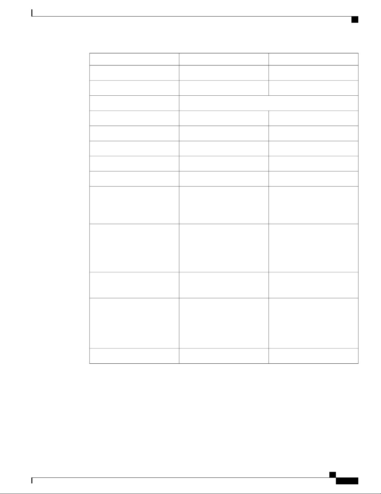
CONTENTS
Preface
CHAPTER 1
Preface ix
Document Revision History ix
Document Audience x
Document Organization x
Document Conventions x
Obtaining Documentation and Submitting a Service Request xii
Overview 1
Cisco ASR 920 Series Routers Features 1
GigabitEthernet Copper Ports 2
GE SFP Ports 2
SFP+ Ports 2
Interface Modules 3
Gigabit Ethernet RJ45 Interface Module (A900-IMA8T) 3
10-Gigabit Ethernet XFP Interface Module (A900-IMA1X) 4
2x1 10 Gigabit Ethernet SFP+ Interface Module (A900-IMA2Z) 5
8-Port 1 Gigabit Ethernet + 1-Port 10 Gigabit Ethernet SFP+ Combination Interface Module
6
8 Port T1/E1 Interface Module (A900-IMA8D) 7
Interface Availability on Interface Modules 7
Front and Back Panel 9
Specifications 12
External Interfaces 14
Network Interfaces 14
Network Timing Interfaces 15
External Alarm Inputs 15
Management Interfaces 15
Cisco ASR-920-24SZ-IM, ASR-920-24SZ-M, ASR-920-24TZ-M Aggregation Services Router Hardware Installation
Guide
iii
Page 4

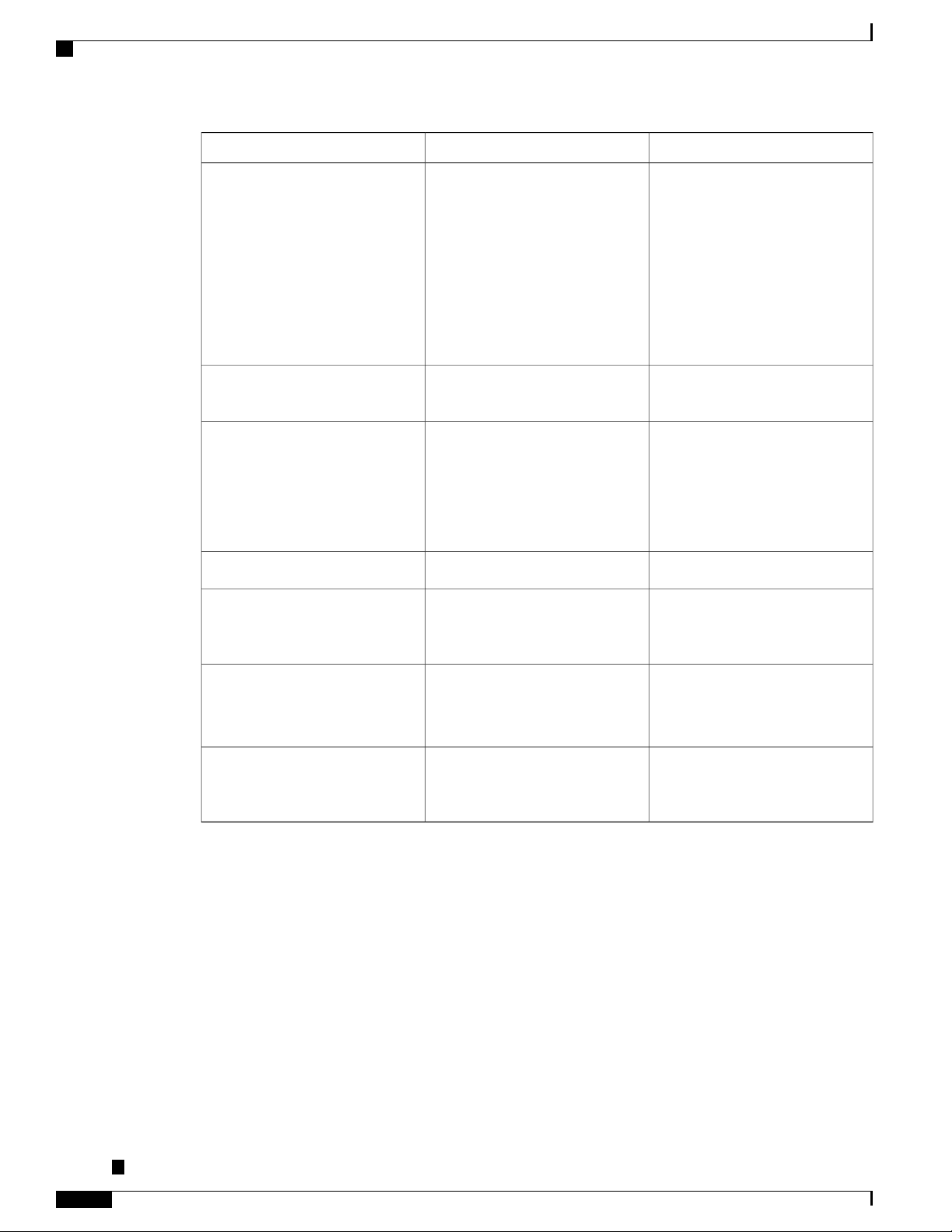
Contents
Power Supply and Fans 15
LED Indicators 16
PWR and STAT LEDs 16
CPU Management Port LEDs 18
SFP LEDs 18
SFP+ LEDs 18
8 T1/E1 Interface Module LEDs 19
RJ-45 LEDs 20
Power Supply Unit LEDs 20
System–Interface LED Behavior 21
Online Insertion and Removal 22
Licensing the Router 23
CHAPTER 2
Preparing for Installation 25
Safety Guidelines 25
Standard Warning Statements 25
Safety Guidelines for Personal Safety and Equipment Protection 26
Safety Precautions for Module Installation and Removal 27
Safety with Electricity 27
Power Supply Considerations 30
Preventing ESD Damage 30
Site Planning 31
General Precautions 31
Site Planning Checklist 31
Site Selection Guidelines 32
Environmental Requirements 32
Physical Characteristics 33
Air Flow Guidelines 33
Air Flow Guidelines for ETSI Rack Installation 36
Floor Loading Considerations 36
Site Power Guidelines 36
Electrical Circuit Requirements 37
Site Cabling Guidelines 37
Asynchronous Terminal Connections 38
Interference Considerations 38
Cisco ASR-920-24SZ-IM, ASR-920-24SZ-M, ASR-920-24TZ-M Aggregation Services Router Hardware Installation
Guide
iv
Page 5

Contents
Electromagnetic Interference 38
Radio Frequency Interference 38
Lightning and AC Power Fault Interference 38
Rack-Mounting Guidelines 39
Precautions for Rack-Mounting 39
Rack Selection Guidelines 39
Equipment Rack Guidelines 40
Locating for Safety 40
Locating for Easy Maintenance 40
Locating for Proper Airflow 41
Installation Checklist 41
Creating a Site Log 42
CHAPTER 3
Receiving the Router 43
Chassis-Lifting Guidelines 44
Tools and Equipment 45
Unpacking and Verifying the Shipped Contents 45
Installing the Router 49
Prerequisites 49
Installing the Router in a Rack 50
Installing the Chassis Brackets 50
Installing the Router Chassis in the Rack 56
Attaching the Cable Guides 59
Wall Mounting the Routers 61
Attaching the Brackets to the Router for Wall-Mounting 62
Mounting Routers on the Wall 62
Installing and Removing the Interface Module 66
Installing the Interface Module 66
Removing the Interface Module 68
Hot-Swapping the Interface Module 69
Installing and Removing the Fan Tray 70
Installing the Fan Tray 70
Removing the Fan Tray 73
Installing the Power Supply 76
Preventing Power Loss 77
Cisco ASR-920-24SZ-IM, ASR-920-24SZ-M, ASR-920-24TZ-M Aggregation Services Router Hardware Installation
Guide
v
Page 6

Contents
Power Connection Guidelines 77
Guidelines for DC-Powered Systems 78
Guidelines for AC-Powered Systems 78
Installing a DC Power Supply 78
Installing a DC Power Supply Module 79
Attaching Cables to the DC Power Supply 80
Powering On the Router 82
Removing and Replacing a DC Power Supply 82
Installing an AC power Supply 84
Installing an AC Power Supply Module 85
Activating an AC Power Supply 86
Removing and Replacing an AC Power Supply 89
Installing and Removing SFP Modules 90
Installing SFP Modules 91
Removing SFP Modules 94
Connecting to the 10/100/1000 Ports 96
Connecting to SFP Modules 97
Connecting to Fiber-Optic SFP Modules 97
Installing the Chassis Ground Connection 98
Power Connection Guidelines 100
Guidelines for DC-Powered Systems 101
Guidelines for AC-Powered Systems 101
Preventing Power Loss 101
Activating a DC Power Supply 102
Activating an AC Power Supply 102
Connecting a Router to the Network 103
Connecting Console Cables 103
Connecting to the USB Serial Port Using Microsoft Windows 103
Connecting to the Console Port Using Mac OS X 105
Connecting to the Console Port Using Linux 106
Installing the Cisco USB Device Driver 106
Uninstalling the Cisco USB Device Driver 107
Connecting to the EIA Console Port 108
Connecting a Management Ethernet Cable 110
Installing and Removing SFP and SFP+ Modules 110
Cisco ASR-920-24SZ-IM, ASR-920-24SZ-M, ASR-920-24TZ-M Aggregation Services Router Hardware Installation
Guide
vi
Page 7

Contents
Connecting a USB Flash Device 110
Removing a USB Flash Device 111
Connecting Timing Cables 111
Connecting a Cable to the BITS Interface 111
Connecting Cables to the GPS Interface 112
Connecting a Cable to the Input 10-Mhz or 1-PPS Interface 112
Connecting a Cable to the Output 10-Mhz or 1-PPS Interface 113
Connecting a Cable to the ToD Interface 113
Connecting Ethernet Cables 114
Connecting Cables to SFP Modules 115
Connector and Cable Specifications 115
CHAPTER 4
CHAPTER 5
Initial Configuration 117
Checking Conditions Prior to System Startup 117
Powering Up the Router 118
Verifying the Front Panel LEDs 121
Verifying the Hardware Configuration 121
Checking Hardware and Software Compatibility 122
Configuring the Router at Startup 122
Accessing the CLI Using the Console 122
Configuring Global Parameters 124
Checking the Running Configuration Settings 125
Saving the Running Configuration to NVRAM 125
Safely Powering Off the Router 125
Automatic Shutdown of the Router 126
Troubleshooting 127
Pinouts 127
BITS Port Pinouts 127
GPS Port Pinout 128
Time-of-Day Port Pinouts 128
Alarm Port Pinouts 129
Management Ethernet Port Pinouts 130
USB Console Port Pinouts 130
USB Flash or MEM Port Pinouts 131
Cisco ASR-920-24SZ-IM, ASR-920-24SZ-M, ASR-920-24TZ-M Aggregation Services Router Hardware Installation
Guide
vii
Page 8

Contents
RJ45C Port Pinouts 131
Optical Fiber Specifications 132
Alarm Conditions 132
CHAPTER 6
CHAPTER 7
Site Log 133
Supported PIDs 135
viii
Cisco ASR-920-24SZ-IM, ASR-920-24SZ-M, ASR-920-24TZ-M Aggregation Services Router Hardware Installation
Guide
Page 9
Preface
The preface describes the revision history, audience, organization, and conventions of the Cisco ASR 920
Series Aggregation Services Routers. It also lists sources for obtaining additional information and technical
assistance from Cisco.
This document covers the following variants of the Cisco ASR 920 Series Aggregation Services Routers:
• ASR-920-24SZ-IM— Twenty Four 1GE Fiber ports, Four 10G ports, and One slot for modular interface
card, with replaceable redundant AC and DC power supplies
• ASR-920-24SZ-M—Twenty Four 1GE Fiber ports and Four 10G ports, with replaceable redundant
AC and DC power supplies
• ASR-920-24TZ-M—Twenty Four 1 GE Copper ports and Four 10G ports, with replaceable redundant
AC and DC power supplies
Document Revision History, page ix
•
Document Audience, page x
•
Document Organization, page x
•
Document Conventions, page x
•
Obtaining Documentation and Submitting a Service Request, page xii
•
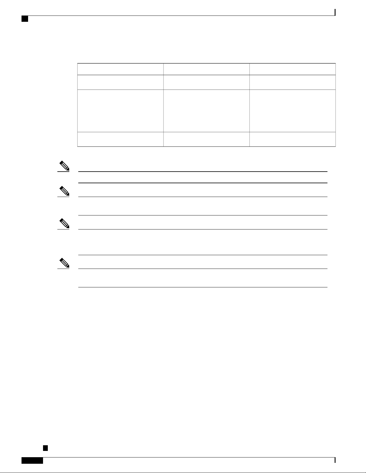
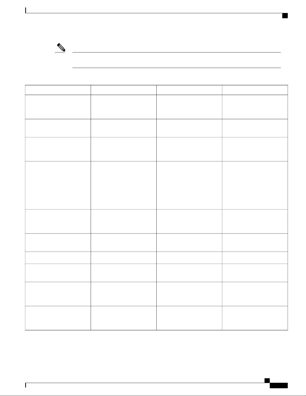
Document Revision History
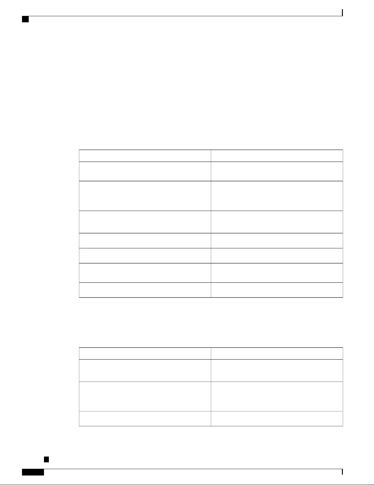
The following table lists the major changes made to this document.
Cisco ASR-920-24SZ-IM, ASR-920-24SZ-M, ASR-920-24TZ-M Aggregation Services Router Hardware Installation
Change SummaryDateRelease
First ReleaseNovember 22, 2014Cisco IOS XE Release 3.14.0S
Guide
ix
Page 10
Document Audience
Document Audience
This guide is intended for users who are responsible for installing the Cisco ASR 920-24SZ-IM,
ASR-920-24SZ-M, ASR-920-24TZ-M Router. It is intended for users who may not be familiar with the initial
configuration and troubleshooting tasks, the relationship among tasks, or the Cisco IOS software commands
necessary to perform particular tasks.
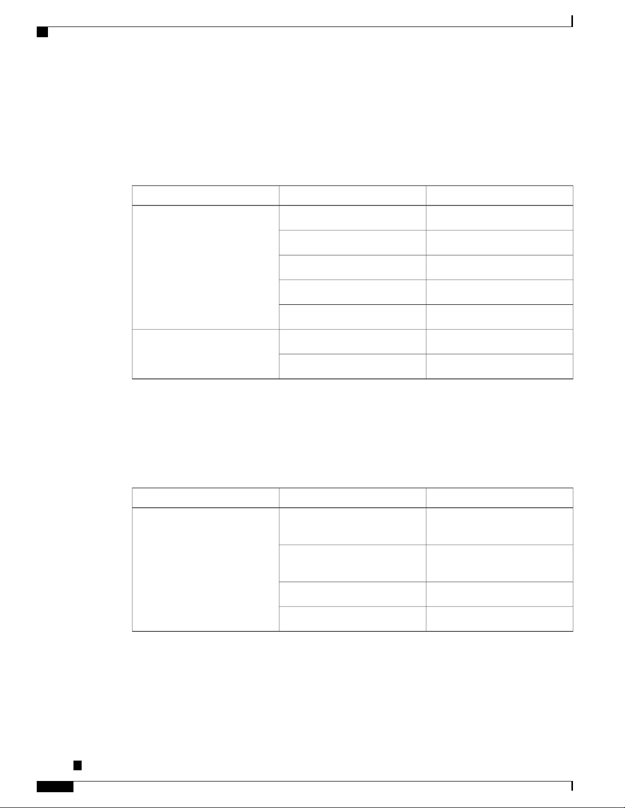
Document Organization
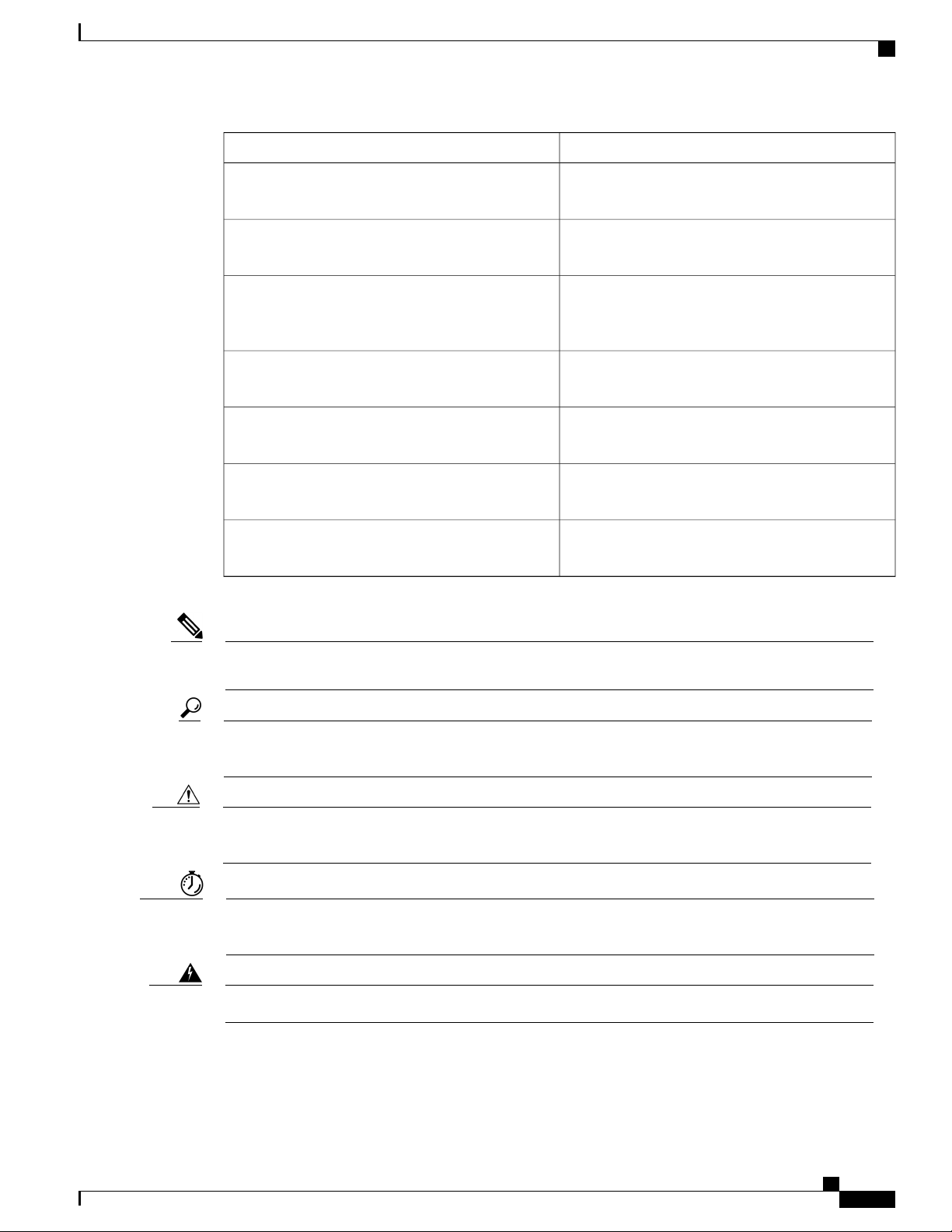
This guide includes the following chapters and appendix:
Preface
DescriptionTitle
Overview, on page 1
Preparing for Installation, on page 25
Installing the Router, on page 49
Site Log, on page 133
Document Conventions
This document uses the following conventions:
Describes the features and specifications of the Cisco
ASR 920 Series Aggregation Services Routers.
Describes the installation of the Cisco ASR
920-24SZ-IM, ASR-920-24SZ-M, ASR-920-24TZ-M
Router at your site.
Describes the installation of router on a rack as well
as installation of its components.
Describes basic router configuration.Initial Configuration, on page 117
Describes troubleshooting information.Troubleshooting, on page 127
Provides a record of actions related to installing and
maintaining the router.
Describes the supported SFPs.Supported PIDs, on page 135
IndicationConvention
bold font
italic font
Cisco ASR-920-24SZ-IM, ASR-920-24SZ-M, ASR-920-24TZ-M Aggregation Services Router Hardware Installation
Guide
x
Commands and keywords and user-entered text
appear in bold font.
Document titles, new or emphasized terms, and
arguments for which you supply values are in italic
font.
Elements in square brackets are optional.[ ]
Page 11
Preface
Document Conventions
IndicationConvention
{x | y | z }
[ x | y | z ]
string
courier font
< >
[ ]
!, #
Required alternative keywords are grouped in braces
and separated by vertical bars.
Optional alternative keywords are grouped in brackets
and separated by vertical bars.
A nonquoted set of characters. Do not use quotation
marks around the string or the string will include the
quotation marks.
Terminal sessions and information the system displays
appear in courier font.
Nonprinting characters such as passwords are in angle
brackets.
Default responses to system prompts are in square
brackets.
An exclamation point (!) or a pound sign (#) at the
beginning of a line of code indicates a comment line.
Note
Tip
Caution
Timesaver
Warning
Means reader take note. Notes contain helpful suggestions or references to material not covered in the
manual.
Means the following information will help you solve a problem. The tips information might not be
troubleshooting or even an action, but could be useful information, similar to a Timesaver.
Means reader be careful. In this situation, you might perform an action that could result in equipment
damage or loss of data.
Means the described action saves time. You can save time by performing the action described in the
paragraph.
Means reader be warned. In this situation, you might perform an action that could result in bodily injury.
Cisco ASR-920-24SZ-IM, ASR-920-24SZ-M, ASR-920-24TZ-M Aggregation Services Router Hardware Installation
Guide
xi
Page 12
Obtaining Documentation and Submitting a Service Request
Preface
Warning
IMPORTANT SAFETY INSTRUCTIONS.
This warning symbol means danger. You are in a situation that could cause bodily injury. Before you
work on any equipment, be aware of the hazards involved with electrical circuitry and be familiar with
standard practices for preventing accidents. Use the statement number provided at the end of each warning
to locate its translation in the translated safety warnings that accompanied this device.
SAVE THESE INSTRUCTIONS
Warning
Statements using this symbol are provided for additional information and to comply with regulatory and
customer requirements.
Obtaining Documentation and Submitting a Service Request
For information on obtaining documentation, submitting a service request, and gathering additional information,
see the monthly What’s New in Cisco Product Documentation, which also lists all new and revised Cisco
technical documentation.
Subscribe to the What’s New in Cisco Product Documentation, which lists all new and revised Cisco technical
documentation as an RSS feed and delivers content directly to your desktop using a reader application. The
RSS feeds are a free service.
Cisco ASR-920-24SZ-IM, ASR-920-24SZ-M, ASR-920-24TZ-M Aggregation Services Router Hardware Installation
Guide
xii
Page 13
CHAPTER 1
Overview
The Cisco ASR 920 Series Aggregation Services Router is a family of modular and fixed configuration
routers that enables Service Providers to provide business, residential, and mobile access services to their
users. It is the Carrier Ethernet access platform providing Ethernet services.
The Cisco ASR 920 Series Routers family complement and extend Cisco’s current and planned Carrier
Ethernet routing portfolio providing a cost optimized, and extended temperature range access platform.
Cisco ASR 920 Series Routers Features, page 1
•
Cisco ASR 920 Series Routers Features
The Cisco ASR 920 Series Routers family includes:
• ASR 920-Modular [ASR-920-24SZ-IM]—This sub-family with 1.5 RU form factor has fixed ENET
interfaces (four 10GE and twenty-four 1GE Fiber), one slot for modular interface card and redundant
modular power supplies (AC/DC). The interface modules from ASR 900 family of routers can be
leveraged for use with this model.
• ASR 920-Fixed [ASR-920-24SZ-M/ASR-920-24TZ-M]—This sub-family with 1 RU form factor has
fixed ENET interfaces (four 10GE and twenty-four 1GE Copper or SFP) and redundant modular power
supplies (AC/DC).
The following table provides a snapshot of the number and type of supported ports:
Table 1: Supported Ports on Cisco ASR 920-24SZ-IM, ASR-920-24SZ-M, ASR-920-24TZ-M Router
Cisco ASR-920-24SZ-IM, ASR-920-24SZ-M, ASR-920-24TZ-M Aggregation Services Router Hardware Installation
Timing PortsType of 10 GE PortType of 1 GE Port10 GE Port1 GE PortASR 920 Sub-family
Built in 4 SFP+24 Fiber424ASR-920-24SZ-IM
ToD and BITSGPS
1 PPS and GPS 10
MHz
NABuilt in 4 SFP+24 Fiber 24 Copper424ASR-920-24SZ-M/ASR-920-24TZ-M
Guide
1
Page 14
GigabitEthernet Copper Ports
GigabitEthernet Copper Ports
Fixed copper GigabitEthernet (GE) interfaces are provided through standard RJ-45 connectors. These ports
support the following features:
Standard 10/100/1000Base-T/TX operation with forced or auto-negotiation for speed and duplex.
•
Automatic crossover (auto-MDIX) for straight-through and crossover connections.
•
Pause flow control as defined by the 802.3x standard.
•
Frame size of 9216 bytes.
•
Synchronous ENET operation that provides its recovered receive clock as an input clock source for the
•
SETS as well as uses the system-wide reference clock to derive its transmit clock.
GE SFP Ports
Overview
SFP+ Ports
The GE SFP ports support the following features:
100Base-FX and 1000Base-X SFP modules.
•
Copper SFP modules
•
Digital optical monitoring as specified by the SFP.
•
Any mix of SFPs is supported unless specifically noted.
•
Pause flow control as defined by the 802.3x standard.
•
Frame size of 9216 bytes.
•
Synchronous ENET operation that provides its recovered receive clock as an input clock source for the
•
SETS as well as uses the system-wide reference clock to derive its transmit clock.
Copper based SFPs do not support synchronous ENET operations.Note
The SFP+ ports support the following features:
Digital optical monitoring as specified by the optical transceiver module.
•
Any mix of SFPs is supported unless specifically noted.
•
Pause flow control as defined by the 802.3x standard.
•
Frame size of 9216 bytes.
•
Cisco ASR-920-24SZ-IM, ASR-920-24SZ-M, ASR-920-24TZ-M Aggregation Services Router Hardware Installation
Guide
2
Page 15
Overview
Interface Modules
The Cisco ASR-920-24SZ-IM Router interface modules are field-replaceable units. In addition to the ports
provided on an RSP, the Cisco ASR-920-24SZ-IM Router supports the interface modules.
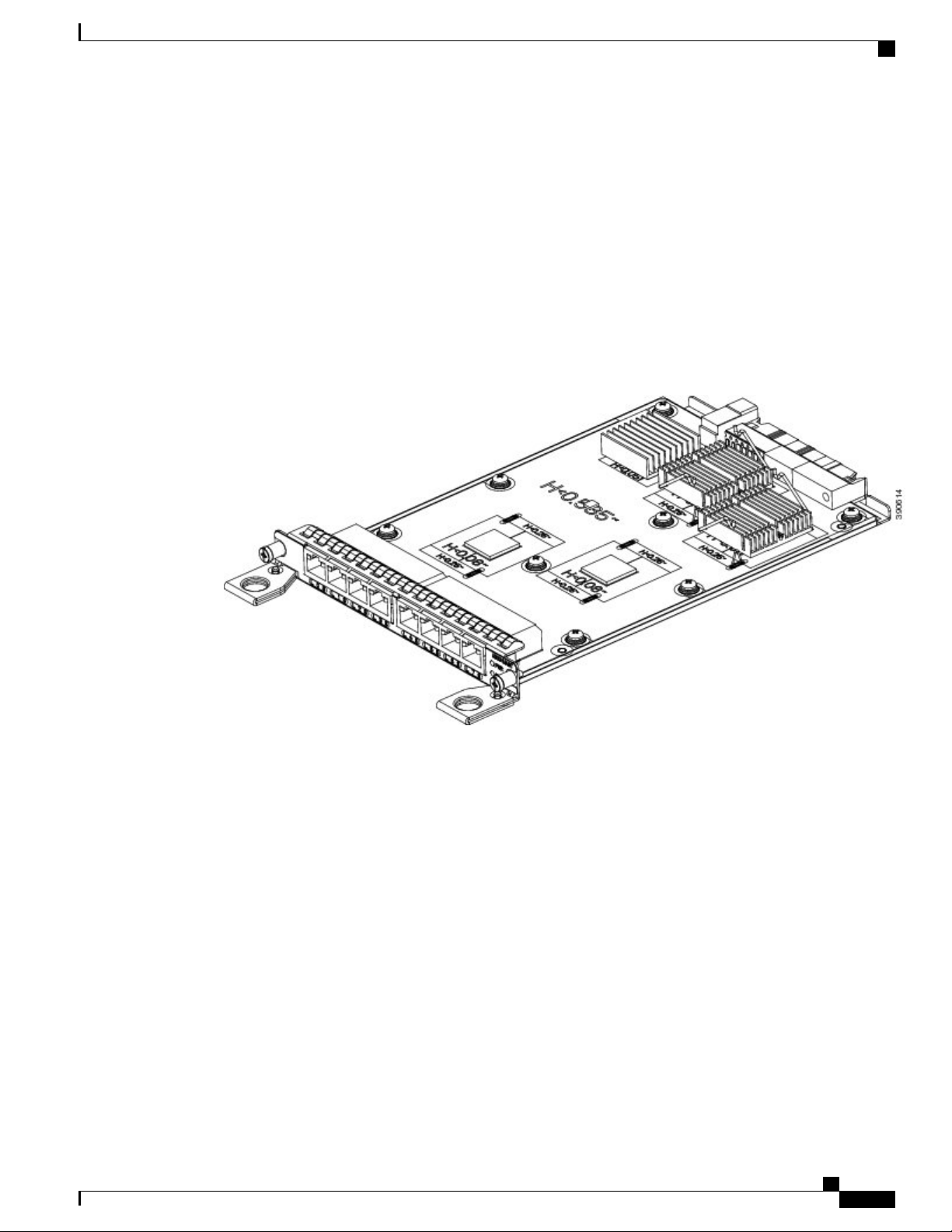
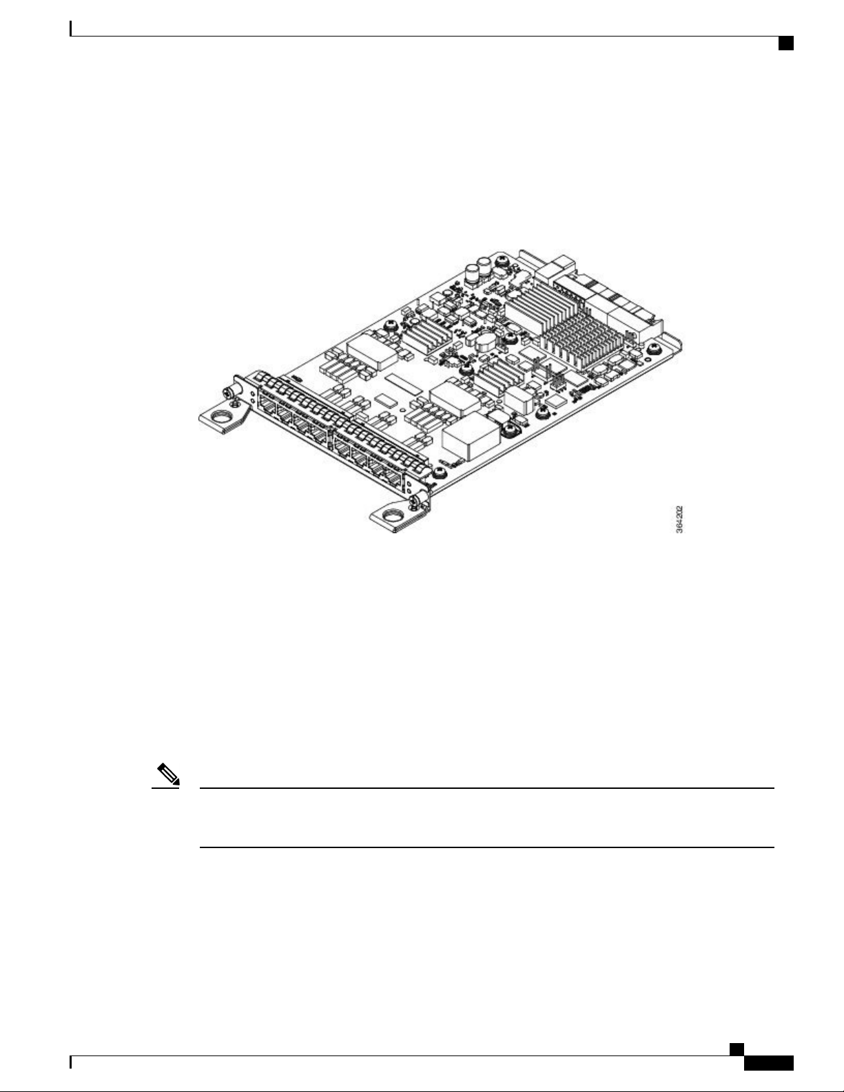
Gigabit Ethernet RJ45 Interface Module (A900-IMA8T)
The Gigabit Ethernet RJ45 interface module provides eight Gigabit Ethernet copper ports. The figure below
shows the interface module.
Figure 1: 8 x 1-Gigabit Ethernet RJ45 (Copper) Interface Module
Interface Modules
For more information about installing an RJ45 Gigabit Ethernet module, see the Installing the Interface
•
Module section.
To determine interfaces available on the RJ45 Gigabit Ethernet module, see the Interface Availability
•
on Interface Modules section.
Cisco ASR-920-24SZ-IM, ASR-920-24SZ-M, ASR-920-24TZ-M Aggregation Services Router Hardware Installation
Guide
3
Page 16
Interface Modules
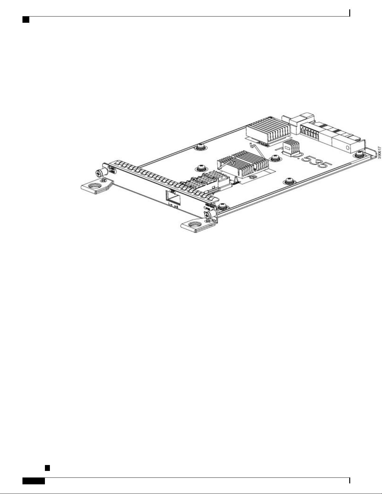
10-Gigabit Ethernet XFP Interface Module (A900-IMA1X)
The 10-Gigabit Ethernet XFP interface module provides a single port supporting a 10-Gigabit Ethernet XFP
module. The following figure shows the interface module.
Figure 2: 1 x 10-Gigabit Ethernet XFP Interface Module
Overview
For more information about installing a 10-Gigabit Ethernet XFP module, see the Installing the Interface
•
Module section.
To determine interfaces available on the 10-Gigabit Ethernet XFP module, see the Interface Availability
•
on Interface Modules section.
For information on supported SFPs, see the Cisco ASR 900 Series Aggregation Services Router Interface
•
Modules Data Sheet at http://www.cisco.com/c/en/us/products/routers/
asr-903-series-aggregation-services-routers/datasheet-listing.html.
Cisco ASR-920-24SZ-IM, ASR-920-24SZ-M, ASR-920-24TZ-M Aggregation Services Router Hardware Installation
Guide
4
Page 17
Overview
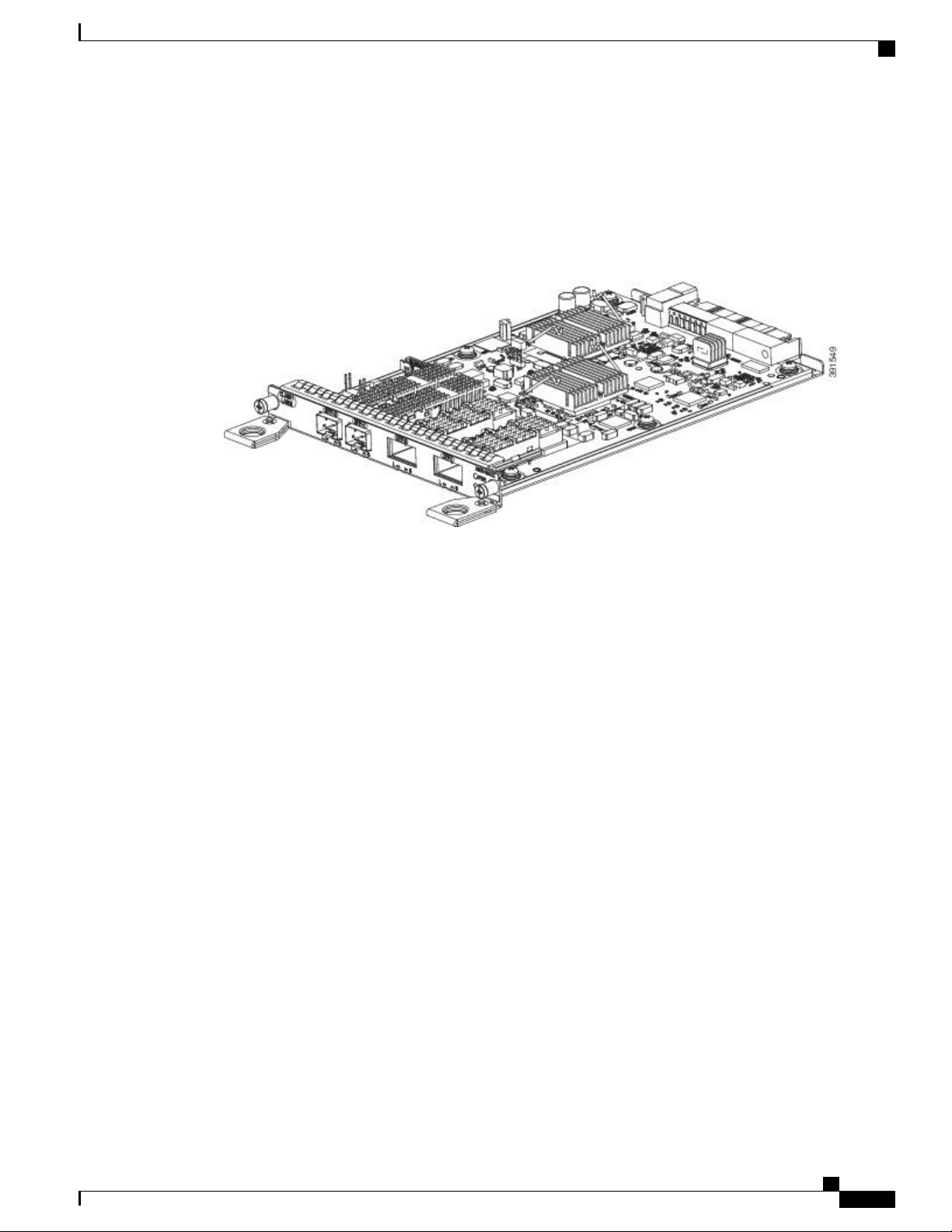
2x1 10 Gigabit Ethernet SFP+ Interface Module (A900-IMA2Z)
The 2-port 10-Gigabit Ethernet interface module provides a dual port supporting a 10-Gigabit Ethernet SFP+
and XFP module.
Figure 3: 2X10 Gigabit Ethernet Interface Module
Interface Modules
For more information about installing the 2X10 GE SFP Gigabit Ethernet module, see the Installing the
•
Interface Module section.
To determine interfaces available on the 2X10 GE SFP Gigabit Ethernet module, see the Interface
•
Availability on Interface Modules section.
For information on supported SFPs, see the Cisco ASR 900 Series Aggregation Services Router Interface
•
Modules Data Sheet at http://www.cisco.com/c/en/us/products/routers/
asr-903-series-aggregation-services-routers/datasheet-listing.html.
Cisco ASR-920-24SZ-IM, ASR-920-24SZ-M, ASR-920-24TZ-M Aggregation Services Router Hardware Installation
Guide
5
Page 18
Overview
Interface Modules
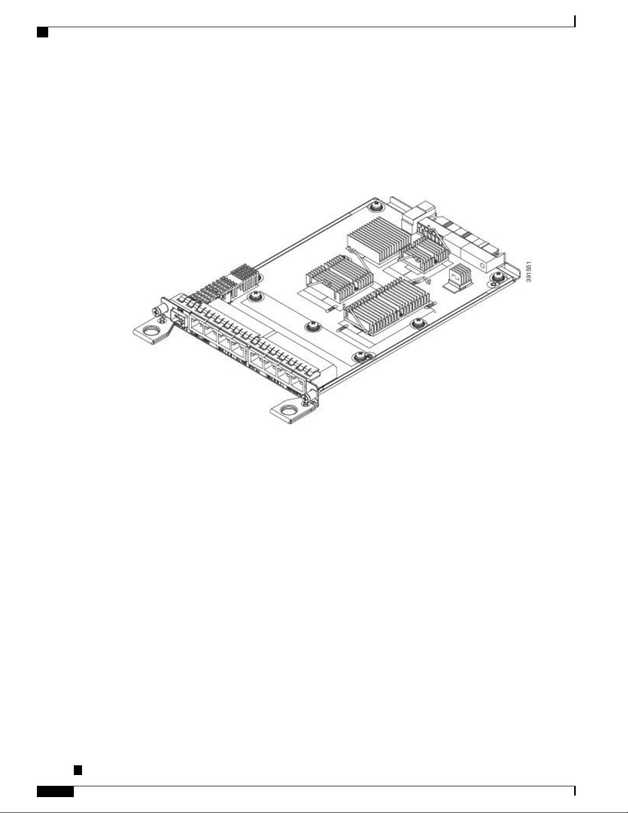
8-Port 1 Gigabit Ethernet + 1-Port 10 Gigabit Ethernet SFP+ Combination Interface Module
This 8-port 1 Gigabit Ethernet (RJ45 Copper) interface module with the 1-port 10 Gigabit Ethernet interface
module is a high density combination interface module. This module supports 8 Gigabit Ethernet Copper
ports and 1 10 Gigabit Ethernet SFP+ port.
Figure 4: 8-port 1 GE (RJ45) + 1-port 10 GE SFP+ Interface Module
Cisco ASR-920-24SZ-IM, ASR-920-24SZ-M, ASR-920-24TZ-M Aggregation Services Router Hardware Installation
Guide
6
Page 19
Overview
8 Port T1/E1 Interface Module (A900-IMA8D)
The 8T1/E1 interface module provides connectivity for up to 8 x T1/E1 ports through RJ48C connectors on
the front panel. The following figure shows the interface module.
Figure 5: 8 x T1/E1 Interface Module
Interface Modules
For more information about installing a 8 Port T1/E1 interface module, see the Installing the Interface
•
Module section.
To determine interfaces available on the 8 Port T1/E1 interface module, see the Interface Availability
•
on Interface Modules section.
For LED indicator information on the 8 Port T1/E1 interface module, see the 8 T1/E1 Interface Module
•
LEDs section.
For RJ45C pinout information on the 8 Port T1/E1 interface module, see the RJ45C Port Pinouts section.
•
Interface Availability on Interface Modules
Note
Cisco ASR-920-24SZ-IM Router does not support over-subscription mode. You must disable the ports
as appropriate to restrict the system usage to 64 Gbps. Enabling all the interfaces in over-subscription
mode can result in an unpredictable system performance.
The following table provides a snapshot of the interfaces available on supported interface modules:
Cisco ASR-920-24SZ-IM, ASR-920-24SZ-M, ASR-920-24TZ-M Aggregation Services Router Hardware Installation
Guide
7
Page 20
Interface Modules
Table 2: Interface Availability on Supported Interface Modules
Overview
Module
QuantityInterface
Interfaces
in
System
Oversubscribed
Resulting
Front Panel
Ports
Disabled
System
DS3/E3OC3/OC12T1/E110GESFPCu
00042400None
16 to 23No00041681A900-IMA8T
Yes00062401A900-IMA2Z
Yes00052401A900-IMA1X
20 to 23No00842001A900-IMA8D
Cisco ASR-920-24SZ-IM, ASR-920-24SZ-M, ASR-920-24TZ-M Aggregation Services Router Hardware Installation
Guide
8
Page 21
Overview
Front and Back Panel
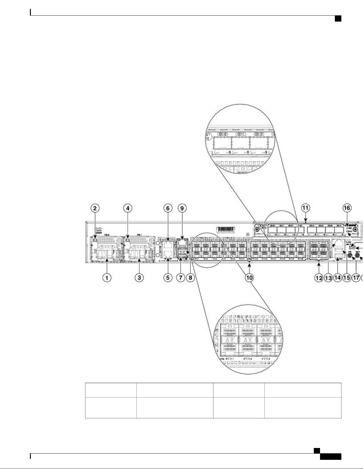
The following figures show the port numbering for the Cisco ASR-920-24SZ-IM Router:
Figure 6: Front Panel of Cisco ASR-920-24SZ-IM Router
Front and Back Panel
4x10GE SFP+12Power Supply 0 (AC or DC)1
2
Alarm port13Power Supply 0 LED (AC or
DC)
Cisco ASR-920-24SZ-IM, ASR-920-24SZ-M, ASR-920-24TZ-M Aggregation Services Router Hardware Installation
Guide
9
Page 22
Front and Back Panel
Overview
USB Console port14Power Supply 1 (AC or DC3
4
DC)
11
module
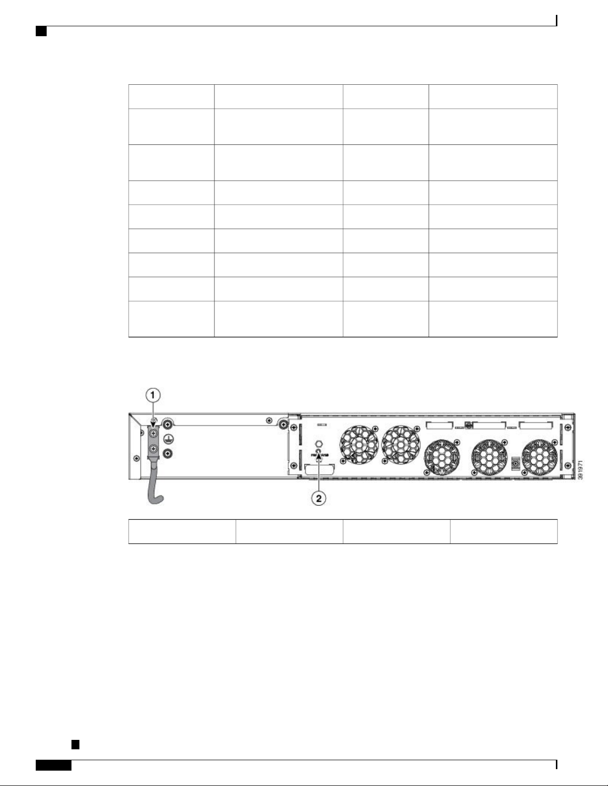
Figure 7: Back Panel of Cisco ASR-920-24SZ-IM Router
USB Memory port15Power Supply 1 LED (AC or
16RJ-48 slot for ToD5
Interface Module (IM) power
LED
1 PPS co-axial connector17RJ-48 slot for BITS6
10 MHz co-axial connector18Console port (TIA/EIA-232F)7
IM Status LED19Auxiliary Console port8
System Status LED20Management port9
Board power LED2124x1GE SFP Fiber ports10
--Slot for ports on the interface
Cisco ASR-920-24SZ-IM, ASR-920-24SZ-M, ASR-920-24TZ-M Aggregation Services Router Hardware Installation
Guide
10
Fan status LED2Grounding lugs1
Page 23
Overview
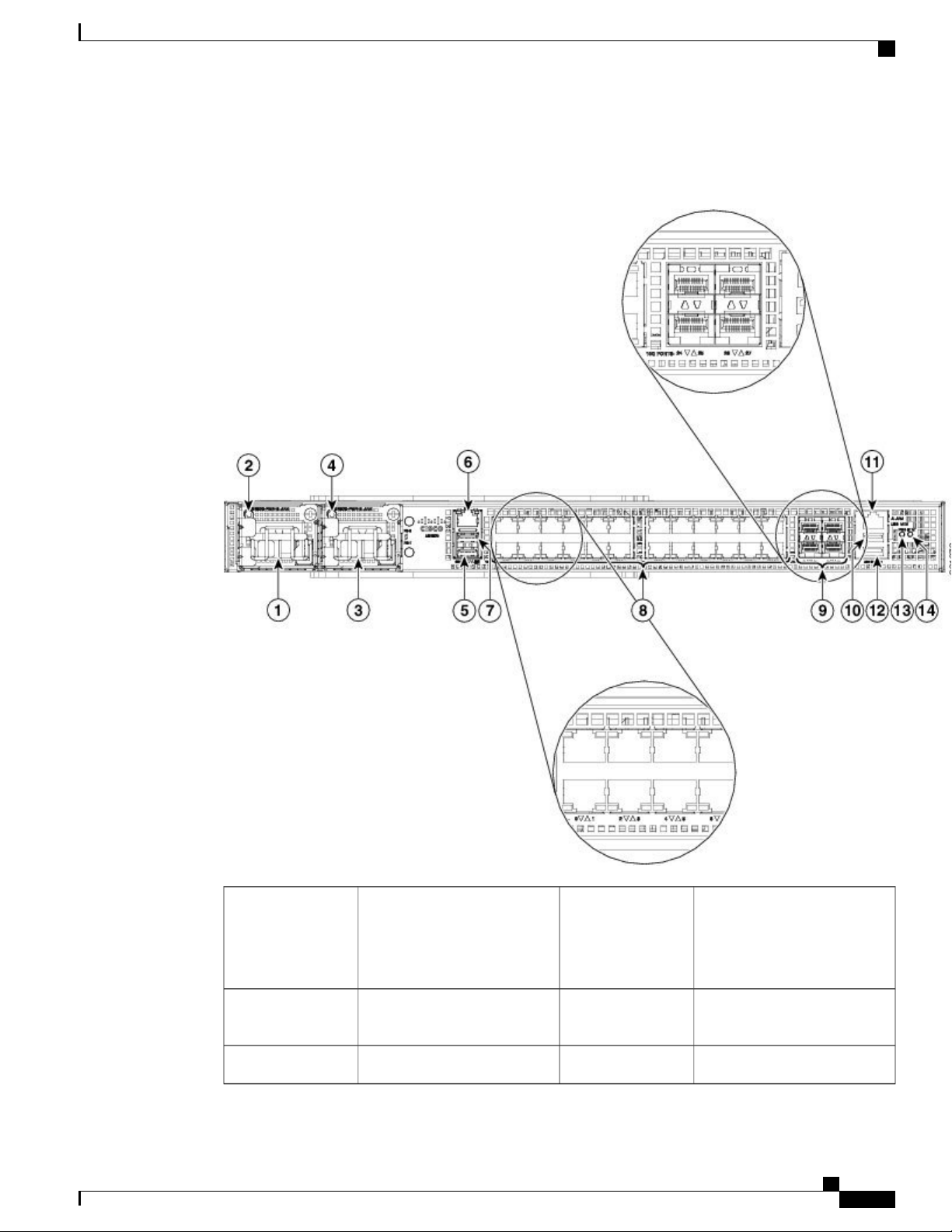
Front and Back Panel
Figure 8: Front Panel of Cisco ASR-920-24SZ-M, ASR-920-24TZ-M Router
8Power Supply 0 (AC or DC)1
24x1GE SFP Fiber (Cisco
ASR-920-24SZ-M)
24x1GE SFP Copper (Cisco
ASR-920-24TZ-M)
2
4x10GE SFP+9Power Supply 0 LED (AC or
DC)
USB Memory port10Power Supply 1 (AC or DC)3
Cisco ASR-920-24SZ-IM, ASR-920-24SZ-M, ASR-920-24TZ-M Aggregation Services Router Hardware Installation
Guide
11
Page 24
Specifications
Overview
4
DC)
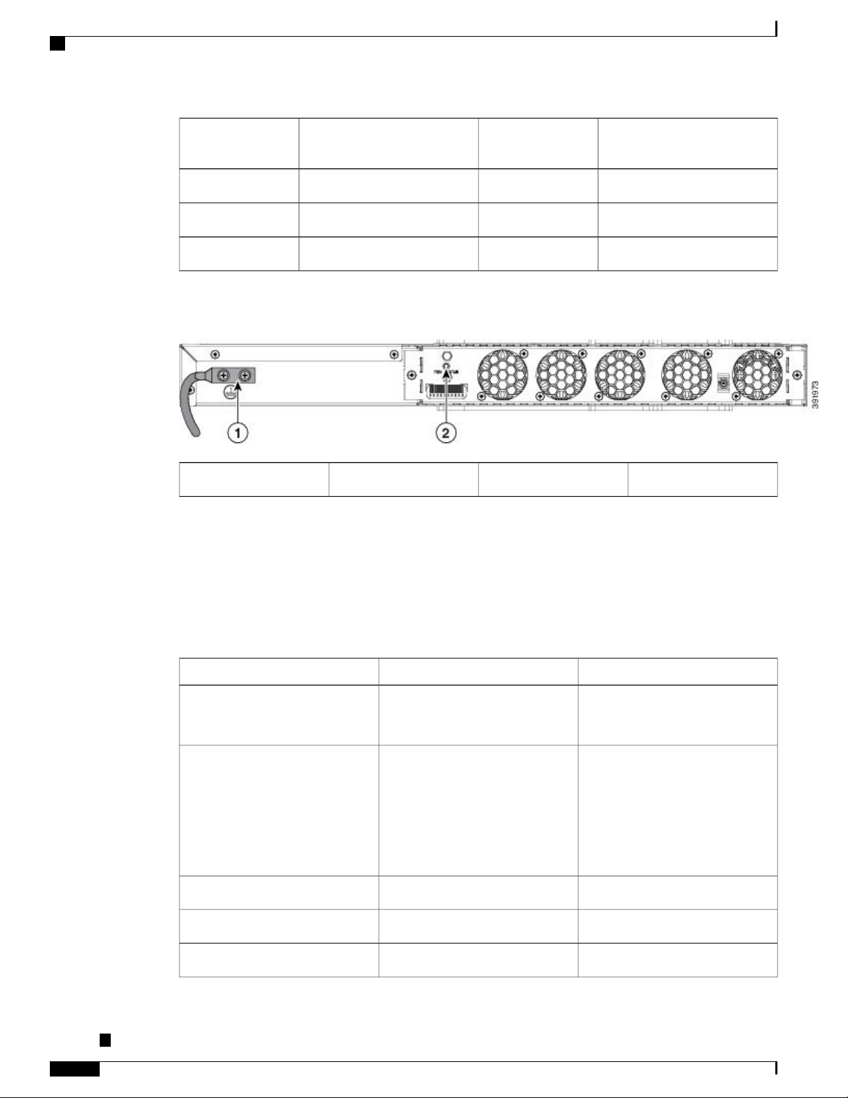
Figure 9: Back Panel of Cisco ASR-920-24SZ-M, ASR-920-24TZ-M Router
Alarm port11Power Supply 1 LED (AC or
USB Console port12Console port (TIA/EIA-232F)5
Board power LED13Management port6
System Status LED14Auxiliary Console port7
Fan status LED2Grounding lugs1
Specifications
The table below describes the other features of Cisco ASR-920-24SZ-IM Router (AC and DC) and Cisco
ASR-920-24SZ-M, ASR-920-24TZ-M Router (AC and DC) Routers.
Table 3: Cisco ASR 920-24SZ-IM, ASR-920-24SZ-M, ASR-920-24TZ-M Router Specifications
ASR-920-24SZ-M, ASR-920-24TZ-MASR-920-24SZ-IMSpecification
DimensionWidth x Depth x Height
Weight
17.5 x 9.43 x 2.6 inches
Note
Dimensions exclude the
PSU and IM handle.
7.08 kg
(inclusive of rack brackets,
twenty-four SFP and four SFP+
optics, two AC PSUs and an IM
card)
17.5 x 9.43 x 1.72 inches
Note
Dimensions exclude the
PSU and IM handle.
ASR-920-24SZ-M: 5.53 kg
ASR-920-24TZ-M: 4.90 kg
(inclusive of rack brackets,
twenty-four SFP (only for
ASR-920-24SZ-M) and four SFP+
optics and two AC PSUs)
One RUOne and a half RURack Unit
Front to backFront to back and side to backAirflow
Front cable accessFront cable accessCable access
Cisco ASR-920-24SZ-IM, ASR-920-24SZ-M, ASR-920-24TZ-M Aggregation Services Router Hardware Installation
Guide
12
Page 25
Overview
Specifications
ASR-920-24SZ-M, ASR-920-24TZ-MASR-920-24SZ-IMSpecification
64 Gbps64 GbpsSystem throughput
NoneInterface moduleModularity
Power Supply
YesYesRedundant
YesYesAC
250 W Maximum250 W MaximumPower Specification
YesYesDC
250 W Maximum250 W MaximumPower Specification
System Power Consumption
Power Dissipation
Operating Temperature/Humidity
Alarms
180 W Maximum, 130 W Typical
(including installed IM)
614.18 BTU/hr Maximum, 443.57
BTU/hr Typical
(including installed IM)
–40º C to 70º C
5-95% RH
4 alarm dry contact inputs
•
(normally open)
LED indicators for critical,
•
major and minor alarms
ASR-920-24SZ-M: 145 W
Maximum, 110 W
TypicalASR-920-24TZ-M: 130 W
Maximum, 100 W Typical
ASR-920-24SZ-M: 494.76 BTU/hr
Maximum, 375.33 BTU/hr Typical
ASR-920-24TZ-M: Max: 443.57
BTU/hr Maximum, 341.21 BTU/hr
Typical
–40º C to 70º C
5-95% RH
4 alarm dry contact inputs
•
(normally open)
LED indicators for critical,
•
major and minor alarms
NoneSupported through IM cardTDM Support
Cisco ASR-920-24SZ-IM, ASR-920-24SZ-M, ASR-920-24TZ-M Aggregation Services Router Hardware Installation
Guide
13
Page 26
External Interfaces
Overview
ASR-920-24SZ-M, ASR-920-24TZ-MASR-920-24SZ-IMSpecification
Mounting option
Port Configuration
Port Numbering
LEDs
Front or rear rail 19 inches or
•
23 inches
ETSI 300 mm cabinet
•
Wall Mount (with only side
•
mount option).
Note
For more information, see
Wall Mounting the
Routers section.
card ports
24x1G SFP – Port [0:23]
4x10G SFP+ – Port [24:27]
Data Port LEDsSystem Status
LEDManagement Port LEDPSU
LEDFan Tray LED
Front or rear rail 19 inches or
•
23 inches
ETSI 300 mm cabinet
•
Wall Mount (with only side
•
mount option)
Note
For more information, see
Wall Mounting the
Routers section.
24x1G and 4x10G ports24x1G and 4x10G ports and IM
24x1G SFP (Fiber) – Port
[0:23](ASR-920-24SZ-M)
24x1G SFP (Copper) – Port
[0:23](ASR-920-24TZ-M)
4x10G SFP+ – Port [24:27]
No combo portsNo combo portsCombo Ports
System Status LEDManagement
Port LEDPSU LEDFan Tray LED
Temperature Sensors
Timing Interfaces
External Interfaces
The Cisco ASR 920-24SZ-IM, ASR-920-24SZ-M, ASR-920-24TZ-M Router have these external physical
interfaces on the front panel:
Network Interfaces
The network interfaces are provided through fixed ports.
• GE SFP ports (fiber)—supports 100/1000 modes (ASR 920-24SZ-IM and ASR-920-24SZ-M)
Five temperature sensors for Board
Two temperature sensors for each
PSU
External ports for BITS/ToDSMA
ports for 1 PPS and 10 M1588v2
and SyncE feature supported
Five temperature sensors for Board
Two temperature sensors for each
PSU
No external timing ports1588v2
and SyncE feature supported
Cisco ASR-920-24SZ-IM, ASR-920-24SZ-M, ASR-920-24TZ-M Aggregation Services Router Hardware Installation
Guide
14
Page 27
Overview
• GE SFP ports (copper)—supports 10/100/1000 operation (ASR-920-24TZ-M)
• 10GE SFP+—supports 10G mode.
Network Timing Interfaces
Network timing interface is available only on Cisco ASR-920-24SZ-IM Router.Note
• BITS input or output—The BITS interfaces support clock recovery from either a T1 at 1.544 MHz or
an E1 at 2.048 MHz, configurable by software. BITS interface is provided through a standard RJ-48
connector on the front panel.
• 1PPS input or output and ToD input or output—This shielded RJ-45 interface is used for input or output
of time-of-day (ToD) and 1PPS pulses. ToD format includes both NTP and IEEE 1588-2008 time
formats.
External Interfaces
The same RS422 pins for 1PPS and TOD are shared between input and output directions. The direction for
each can be independently configurable through software.
• GPS 10 Mhz input and output—10 MHz input for GPS Synchronization. This connector on the front
panel can provide 10MHz output as well from Cisco ASR-920-24SZ-IM Router. The direction can be
configured using software.
• GPS 1 PPS input and output—1 PPS input for GPS Synchronization. This connector on the front panel
can provide 1 PPS output as well from Cisco ASR-920-24SZ-IM Router. The direction can be configured
using software.
External Alarm Inputs
The Cisco ASR 920-24SZ-IM, ASR-920-24SZ-M, ASR-920-24TZ-M Router supports four dry contact alarm
inputs through an RJ-45 jack on the front panel.
• Normally Open—indicates that no current flows through the alarm circuit and the alarm is generated
when the current is flowing.
Each alarm input can be provisioned as critical, major, or minor.
Management Interfaces
The Cisco ASR 920-24SZ-IM, ASR-920-24SZ-M, ASR-920-24TZ-M Router have the following management
interfaces:
Power Supply and Fans
The Cisco ASR 920-24SZ-IM, ASR-920-24SZ-M, ASR-920-24TZ-M Router support either AC or DC power
supplies in a 1+1 redundant configuration. The PSUs are hot-swappable. Load is shared between PSUs when
both the PSUs are inserted and powered-up. Status LED provided on both AC and DC PSU indicates the
status and output condition.
Cisco ASR-920-24SZ-IM, ASR-920-24SZ-M, ASR-920-24TZ-M Aggregation Services Router Hardware Installation
Guide
15
Page 28
External Interfaces
Overview
Table 4: Power Supply Specification
DCACSpecification
Note
Note
Voltage
Current
100 V – 240 V, 50/60Hz
2.6 A through a standard C16 type
receptacle
-48/-60 V or 24 V
5.5 A –48/–60 V
11 A –24 V
through a two-position terminal
block
260 W (ASR-920-PWR-D)260 W (ASR-920-PWR-A)Input Power
DC PSU can be switched on or off using a switch on the front panel of the DC PSU.Note
For DC PSU, the UVP and OVP limits vary depending on the input voltage applied at power up: For
-48/-60 V: UVP= -36 Vdc and OVP = -72 Vdc For 24 V: UVP =18 Vdc and OVP = 32 Vdc
This product requires surge protection as part of the building installation. To comply with the Telcordia
GR-1089 NEBS standard for electromagnetic compatibility and safety, an external surge protective device
(SPD) is required at the AC power service equipment.
Note
For DC systems, if a surge of more than 1KV is expected, add an appropriate external surge protective
device.
The Cisco ASR 920-24SZ-IM, ASR-920-24SZ-M, ASR-920-24TZ-M Router have removable fan tray as part
of the system. The fan tray is hot-swappable. The system is designed to operate at its maximum operating
temperature of 70º C and at 65º C in case of failure of a single fan, for a maximum of four hours.
LED Indicators
This section describes the different types of LEDs and their behavior.
PWR and STAT LEDs
The PWR and STAT LEDs are available on the front panel. These LEDs provide power on the board (PWR)
and overall router health (STAT) status. During power up state, these LEDs provide booting status and report
errors.
Cisco ASR-920-24SZ-IM, ASR-920-24SZ-M, ASR-920-24TZ-M Aggregation Services Router Hardware Installation
Guide
16
Page 29
Overview
External Interfaces
Note
The digital code signing functionality validates the integrity and authenticity of the ROMMON image
before booting it.
Table 5: PWR and STAT LED Indications
OffAmber
AmberFlashing Amber and Green
alternatively
OffFlashing Amber and Green
alternatively
Power in the system is all right
and FPGA configuration is
taking place.
FPGA Image Validation Error.RedAmber
Upgrade FPGA image error,
continuing with Golden FPGA
image.
FPGA configuration successful
and Digital code signing
successfully validated FPGA
image. Digital code signing
passed the control to
Microloader to boot
ROMMON.
CommentIndicationSTAT LED statePWR LED State
Permanent Amber/Off indicates
FPGA configuration failure.
System is in unresponsive state.
No console messages.
—
—
alternatively
RedFlashing Amber and Green
Digital code signing reported
failure in ROMMON image
System is in unresponsive state.
No console messages.
validation.
ZTP process has begun.Flashing AmberGreen
Both LEDs turn Green once
provisioning is complete.
IOS-XE image is booting.OffGreen
GreenGreen
Successfully booted and system
—
is operating normally.
AmberGreen
A minor alarm or
—
synchronization is in Holdover
or free-running mode
RedGreen
A major or critical alarm (high
—
temperature reported for any
sensor) or multiple fan failure.
Cisco ASR-920-24SZ-IM, ASR-920-24SZ-M, ASR-920-24TZ-M Aggregation Services Router Hardware Installation
Guide
17
Page 30
External Interfaces
CPU Management Port LEDs
The LED for the 10/100/1000 Management port is integrated on the connector itself. There are two LEDs in
the connector—the LED on the left indicates the Link/Activity status and the LED on the right indicates the
duplex status of the link.
Table 6: CPU Management Port LED Indication
Overview
IndicationLED StateLED
Link up in 1000 MbpsGreenLeft
Activity in 1000 MbpsBlinking Green
Link up in 100/10 MbpsAmber/Orange
Activity in 100/10 MbpsBlinking Amber/Orange
Link downOff
SFP LEDs
Link up in full duplexGreenRight
Link up in half duplexOff
Each SFP port has an LED indicator. The LED is configured such that the up arrow indicates the port on the
upside and the down arrow indicates the port on the downside.
Table 7: SFP Port LED Indication
IndicationLED StateLED
GreenLabeled same as the SFP port
number
Blinking Green
Link up in
1000Base-X/100Base-FX
Activity in 1000
Base-X/100Base-FX
Fault/ErrorYellow
Link downOff
SFP+ LEDs
Each SFP+ port has an LED indicator.
Cisco ASR-920-24SZ-IM, ASR-920-24SZ-M, ASR-920-24TZ-M Aggregation Services Router Hardware Installation
Guide
18
Page 31

Overview
Table 8: SFP+ Port LED Indication
number
8 T1/E1 Interface Module LEDs
The table below summarizes the LEDs for the 8 x T1/E1 interface module.
Table 9: 8 x T1/E1 Interface Module LEDs
External Interfaces
IndicationLED StateLED
Link up in 10GGreenLabeled same as the SFP port
Activity in 10GBlinking Green
Fault/ErrorYellow
Link downOff
Blinking green
Amber
Blinking amber
IndicationLED StateLED
ActiveGreenActive
Off All ports upGreenPort
Operationally
down; card is
disabled or shut
down
All ports up and
one or more
ports in a
loopback state
One or more
configured ports
are down
One or more
configured ports
are down and at
least one
configured port
is in a loopback
state
Off
All ports
disabled or shut
down
Cisco ASR-920-24SZ-IM, ASR-920-24SZ-M, ASR-920-24TZ-M Aggregation Services Router Hardware Installation
Guide
19
Page 32

External Interfaces
Overview
IndicationLED StateLED
RJ-45 LEDs
Status(STAT)
GreenPower (PWR)
Off
Off
All power rails
are within
supported range
DisabledRed
No power to the
Interface
Module
FailedRedOperating
Disabled or
powered-down
BootingBlinking red
ActiveGreen
Each RJ-45 port has two LED indicators. Left LED indicates the Link status; right LED indicates the status
of the duplex LED.
Table 10: RJ-45 LED Indication
Power Supply Unit LEDs
Each power supply unit has a corresponding LED on the front panel.
IndicationLED StateLED
Link up in 10/100/1000Base-TGreenLeft
Activity in 10/100/1000Base-TBlinking Green
Fault/ErrorYellow
Link downOff
Link up in full duplexGreenRight
Link up in half duplexOff
Cisco ASR-920-24SZ-IM, ASR-920-24SZ-M, ASR-920-24TZ-M Aggregation Services Router Hardware Installation
Guide
20
Page 33

Overview
External Interfaces
Table 11: PSU LED Indication
IndicationLED StateLED
System–Interface LED Behavior
Table 12: 1G Copper and 1G SFP LED Indication
(media-type RJ-45)
GreenOK
Red
Power Supply is working and 12V
output is alright.
12V output failure (Either input not
present or fault in the power supply
unit).
1G SFP Port LEDs1G Copper Port LEDs (Link/Duplex)Event
OffOff/OffROMMON
OffOff/OffIOS Shut
YellowYellow/OffIOS No shut (cable disconnect)
OffGreen/GreenIOS No shut (cable connect)
(media-type SFP)
(media-type auto)
Table 13: Management Port LED Indication
10G Port LEDsEvent
OffROMMON (cable connect)
GreenOff/OffIOS No shut (cable connect)
GreenOff/OffIOS No shut (cable connect)
Management Port LEDs
(Link/Duplex)
Green/Green (1000 Mbps, Full
Duplex)
Orange/Green (100/10 Mbps, Full
Duplex)
Off/OffOffROMMON (cable disconnect)
Off/OffOffIOS Shut
Off/OffOrangeIOS No shut (cable disconnect)
Cisco ASR-920-24SZ-IM, ASR-920-24SZ-M, ASR-920-24TZ-M Aggregation Services Router Hardware Installation
Guide
21
Page 34

External Interfaces
Overview
Online Insertion and Removal
The Cisco ASR 920-24SZ-IM, ASR-920-24SZ-M, ASR-920-24TZ-M Router supports the following OIR
operations:
When an SFP is removed, there is no effect on traffic flowing on other ports.
•
When an SFP is installed, the system initializes that port for operation based upon the current
•
configuration. If the inserted SFP is incompatible with the current configuration for that port, the port
does not become operational until the configuration is updated.
Both power supplies are installed and active and the load may be shared between them or a single PSU
•
could support the whole load. When a power supply is not working or the input cable is removed, the
remaining power supply takes the entire load without disruption.
Except for TDM IM, you can hot-swap an interface module with a similar interface module on Cisco
•
ASR-920-24SZ-IM Router. For more information, see Hot-Swapping the Interface Module section.
When a fan tray is removed or replaced, there is no need to power down the router. However, when the
•
fan tray is removed from chassis the router shuts down automatically after some time, depending on the
ambient temperature. The time duration before the router shuts down is shown in the table below:
10G Port LEDsEvent
Management Port LEDs
(Link/Duplex)
GreenIOS No shut (cable connect)
Green/Green in 1G mode
Orange/Green in 100/10M mode
Table 14: Cisco ASR-920-24SZ-IM Router Shut Down Time Table
1
2
–10 to –5
–4 to 15
Shut Down Time (Minimum)Inlet Ambient Temperature (ºCelsius)Sl.
14 minutes
8 minutes
6 minutes 30 seconds16 to 293
4 minutes 30 seconds30 to 404
3 minutes 20 seconds41 to 445
2 minutes 50 seconds45 to 496
2 minutes 10 seconds50 to 547
1 minutes 35 seconds55 to 598
1 minute60 to 649
Cisco ASR-920-24SZ-IM, ASR-920-24SZ-M, ASR-920-24TZ-M Aggregation Services Router Hardware Installation
Guide
22
Page 35

Overview
Licensing the Router
The Cisco ASR 920-24SZ-IM, ASR-920-24SZ-M, ASR-920-24TZ-M Router support the following types of
licenses:
External Interfaces
Shut Down Time (Minimum)Inlet Ambient Temperature (ºCelsius)Sl.
35 seconds65 and above10
• Port Licensing—Port Upgrade license is available as a "Pay as you Grow" model.
1G upgrade license
◦
10G upgrade license
◦
• Bulk licensing—Bulk port licensing allows you to enable all the ports with a single license.
• Timing license (1588)—Timing license is required if the router is used as a master clock.
Note
Advanced Metro IP Access
•
Metro IP Access
•
Metro Access (default)
•
The following methods are used to activate the above licenses:
• Cisco Software Licensing—The Cisco Software License Activation feature is a set of processes and
components to activate Cisco software feature sets by obtaining and validating fee-based Cisco software
licenses.
Licenses generated by the Cisco Software Licensing are tied to the UDI of the chassis and a corresponding
watchtower device certificate (WDC) is stored in the system.
• Cisco Smart Licensing—Smart Licensing is usage-based licensing where devices register with the Cisco
Secure server.
Cisco ASR-920-24SZ-IM, ASR-920-24SZ-M, ASR-920-24TZ-M Aggregation Services Router Hardware Installation
Guide
23
Page 36

External Interfaces
Overview
Cisco ASR-920-24SZ-IM, ASR-920-24SZ-M, ASR-920-24TZ-M Aggregation Services Router Hardware Installation
Guide
24
Page 37

Preparing for Installation
This chapter describe how to prepare for the installation of the Cisco ASR 920-24SZ-IM, ASR-920-24SZ-M,
ASR-920-24TZ-M Router at your site.
Safety Guidelines, page 25
•
Site Planning, page 31
•
Receiving the Router, page 43
•
Safety Guidelines
Before you begin the installation of the Cisco ASR 920-24SZ-IM, ASR-920-24SZ-M, ASR-920-24TZ-M
Router, review the safety guidelines in this chapter to avoid injuring yourself or damaging the equipment.
In addition, before replacing, configuring, or maintaining the Cisco ASR 920-24SZ-IM, ASR-920-24SZ-M,
ASR-920-24TZ-M Router, review the safety warnings listed in the Regulatory Compliance and Safety
Information for the Cisco ASR 920 Series Router document.
CHAPTER 2
Standard Warning Statements
Warning
Warning
To prevent bodily injury when mounting or servicing this unit in a rack, you must take special precautions
to ensure that the system remains stable. The following guidelines are provided to ensure your safety:
This unit should be mounted at the bottom of the rack if it is the only unit in the rack. When mounting
this unit in a partially filled rack, load the rack from the bottom to the top with the heaviest component at
the bottom of the rack. If the rack is provided with stabilizing devices, install the stabilizers before mounting
or servicing the unit in the rack. Statement 1006
This unit is intended for installation in restricted access areas. A restricted access area can be accessed
only through the use of a special tool, lock and key, or other means of security. Statement 1017
Cisco ASR-920-24SZ-IM, ASR-920-24SZ-M, ASR-920-24TZ-M Aggregation Services Router Hardware Installation
Guide
25
Page 38

Safety Guidelines for Personal Safety and Equipment Protection
Preparing for Installation
Warning
Warning
Warning
Warning
Ultimate disposal of this product should be handled according to all national laws and regulations. Statement
1040
To prevent the system from overheating, do not operate it in an area that exceeds the maximum
recommended ambient temperature of 158°F (70°C). Statement 1047
The chassis should be mounted on a rack that is permanently affixed to the building. Statement 1049Warning
IMPORTANT SAFETY INSTRUCTIONS: This warning symbol means danger. You are in a situation
that could cause bodily injury. Before you work on any equipment, be aware of the hazards involved with
electrical circuitry and be familiar with standard practices for preventing accidents. Use the statement
number provided at the end of each warning to locate its translation in the translated safety warnings that
accompanied this device. Statement 1071
This is a Class A Device and is registered for EMC requirements for industrial use. The seller or buyer
should be aware of this. If this type was sold or purchased by mistake, it should be replaced with a
residential-use type. Statement 294
Warning
This is a class A product. In a domestic environment this product may cause radio interference in which
case the user may be required to take adequate measures. Statement 340
Warning
This equipment is in compliance with the essential requirements and other relevant provisions of Directive
1999/5/EC. Statement 287
For other standard warning messages and their translations, see the Regulatory Compliance and Safety
Information for the Cisco ASR 920 Series Aggregation Services Router document.
Safety Guidelines for Personal Safety and Equipment Protection
The following guidelines help ensure your safety and protect the equipment. This list does not include all the
potentially hazardous situations. Therefore, you should be on alert.
Before moving the system, always disconnect all the power cords and interface cables.
•
Never assume that power is disconnected from a circuit; always check.
•
Before and after installation, keep the chassis area clear and dust free.
•
Keep tools and assembly components away from walk areas where you or others could trip over them.
•
Do not work alone if potentially hazardous conditions exist.
•
Cisco ASR-920-24SZ-IM, ASR-920-24SZ-M, ASR-920-24TZ-M Aggregation Services Router Hardware Installation
Guide
26
Page 39

Preparing for Installation
Safety Precautions for Module Installation and Removal
Do not perform any action that creates a potential hazard to people or makes the equipment unsafe.
•
Do not wear loose clothing that may get caught in the chassis.
•
When working under conditions that may be hazardous to your eyes, wear safety glasses.
•
Safety Precautions for Module Installation and Removal
Be sure to observe the following safety precautions when you work on the router.
To see the translations of the warnings that appear in this publication, see the Regulatory Compliance and
Safety Information for the Cisco ASR 920 Series Router document.
Class 1 laser product. Statement 1008Warning
Do not stare into the beam or view it directly with optical instruments. Statement 1011Warning
Invisible laser radiation present. Statement 1016Warning
Warning
Invisible laser radiation may be emitted from disconnected fibers or connectors. Do not stare into beams
or view directly with optical instruments. Statement 1051
Safety with Electricity
Warning
Warning
Warning
Before working on a chassis or working near power supplies, unplug the power cord on AC units; disconnect
the power at the circuit breaker on DC units. Statement 12
Before working on equipment that is connected to power lines, remove jewelry (including rings, necklaces,
and watches). Metal objects will heat up when connected to power and ground and can cause serious burns
or weld the metal object to the terminals. Statement 43
Avoid using or servicing any equipment that has outdoor connections during an electrical storm.
There may be a risk of electric shock from lightning. Statement 1088
Cisco ASR-920-24SZ-IM, ASR-920-24SZ-M, ASR-920-24TZ-M Aggregation Services Router Hardware Installation
Guide
27
Page 40

Safety with Electricity
Preparing for Installation
Warning
Warning
Warning
Warning
Before performing any of the following procedures, ensure that power is removed from the DC circuit.
Statement 1003
Read the installation instructions before connecting the system to the power source. Statement 1004Warning
This product relies on the building’s installation for short-circuit (overcurrent) protection. For a DC
installation, ensure that the branch circuit breaker is rated a maximum 15A for DC systems. For AC
systems, 15A for voltages greater than 200Vac; 20A for voltages below 127Vac. Statement 1005
Take care when connecting units to the supply circuit so that wiring is not overloaded. Statement 1018Warning
The plug-socket combination must be accessible at all times, because it serves as the main disconnecting
device. Statement 1019
To avoid electric shock, do not connect safety extra-low voltage (SELV) circuits to telephone-network
voltage (TNV) circuits. LAN ports contain SELV circuits, and WAN ports contain TNV circuits. Some
LAN and WAN ports both use RJ45 connectors. Use caution when connecting cables. Statement 1021
Warning
Warning
Warning
A readily accessible two-poled disconnect device must be incorporated in the fixed wiring. Statement
1022
To reduce the risk of fire, use only 26 AWG or larger telecommunication line cord. Statement 1023Warning
This equipment must be grounded. Never defeat the ground conductor or operate the equipment in the
absence of a suitably installed ground conductor. Contact the appropriate electrical inspection authority
or an electrician if you are uncertain that suitable grounding is available. Statement 1024
Use copper conductors only. Statement 1025Warning
This unit might have more than one power supply connection. All connections must be removed to
de-energize the unit. Statement 1028
Cisco ASR-920-24SZ-IM, ASR-920-24SZ-M, ASR-920-24TZ-M Aggregation Services Router Hardware Installation
Guide
28
Page 41

Preparing for Installation
Safety with Electricity
Warning
Warning
Warning
Warning
To prevent personal injury or damage to the chassis, never attempt to lift or tilt the chassis using the
handles on modules (such as power supplies, fans, or cards); these types of handles are not designed to
support the weight of the unit. Statement 1032
Connect the unit only to DC power source that complies with the safety extra-low voltage (SELV)
requirements in IEC 60950 based safety standards. Statement 1033
When installing or replacing the unit, the ground connection must always be made first and disconnected
last. Statement 1046
This equipment must be grounded. Never defeat the ground conductor or operate the equipment in the
absence of a suitably installed ground conductor. Contact the appropriate electrical inspection authority
or an electrician if you are uncertain that suitable grounding is available. Statement 1024
Installation of the equipment must comply with local and national electrical codes. Statement 1074Warning
Warning
Hazardous voltage or energy may be present on power terminals. Always replace cover when terminals
are not in service. Be sure uninsulated conductors are not accessible when cover is in place. Statement
1086
To see the safety with electricity, see the Regulatory Compliance and Safety Information for the Cisco ASR
920 Series Aggregation Services Router document.
When working on equipment powered by electricity, follow these guidelines:
• Locate the room’s emergency power-off switch. If an electrical accident occurs, you will be able to
quickly turn off the power.
Before starting work on the system, turn off the DC main circuit breaker and disconnect the power
•
terminal block cable.
Before doing the following, disconnect all power:
•
Working on or near power supplies
◦
Installing or removing a router chassis or network processor module
◦
Performing most hardware upgrades
◦
Never install equipment that appears damaged.
•
Carefully examine your work area for possible hazards, such as moist floors, ungrounded power extension
•
cables, and missing safety grounds.
Never assume that power is disconnected from a circuit; always check.
•
Cisco ASR-920-24SZ-IM, ASR-920-24SZ-M, ASR-920-24TZ-M Aggregation Services Router Hardware Installation
Guide
29
Page 42

Power Supply Considerations
Never perform any action that creates a potential hazard to people or makes the equipment unsafe.
•
If an electrical accident occurs, proceed as follows:
•
In addition, use the following guidelines when working with any equipment that is disconnected from a power
source, but still connected to telephone wiring or network cabling:
Never install telephone wiring during a lightning storm.
•
Never install telephone jacks in wet locations unless the jack is specifically designed for it.
•
Never touch uninsulated telephone wires or terminals unless the telephone line is disconnected at the
•
network interface.
Preparing for Installation
Use caution, and do not become a victim yourself.
◦
Turn off power to the router.
◦
If possible, send another person to get medical aid. Otherwise, determine the condition of the
◦
victim, and then call for help.
Determine whether the person needs rescue breathing or external cardiac compressions; then take
◦
appropriate action.
When installing or modifying telephone lines, use caution.
•
Power Supply Considerations
Check the power at your site to ensure that you are receiving clean power (free of spikes and noise). Install a
power conditioner, if necessary.
Preventing ESD Damage
Warning
This equipment needs to be grounded. Use a green and yellow 6 AWG ground wire to connect the host
to earth ground during normal use. Statement 383
Electrostatic discharge (ESD) can damage equipment and impair electrical circuitry. ESD may occur when
electronic printed circuit cards are improperly handled and can cause complete or intermittent failures. When
removing and replacing modules, always follow ESD prevention procedures:
Ensure that the router chassis is electrically connected to earth ground.
•
Wear an ESD-preventive wrist strap, ensuring that it makes good skin contact. To channel unwanted
•
ESD voltages safely to ground, connect the clip to an unpainted surface of the chassis frame. To guard
against ESD damage and shocks, the wrist strap and cord must operate effectively.
If no wrist strap is available, ground yourself by touching a metal part of the chassis.
•
When installing a component, use any available ejector levers or captive installation screws to properly
•
seat the bus connectors in the backplane or midplane. These devices prevent accidental removal, provide
proper grounding for the system, and help to ensure that bus connectors are properly seated.
Cisco ASR-920-24SZ-IM, ASR-920-24SZ-M, ASR-920-24TZ-M Aggregation Services Router Hardware Installation
Guide
30
Page 43

Preparing for Installation
Site Planning
When removing a component, use available ejector levers or captive installation screws, if any, to release
•
the bus connectors from the backplane or midplane.
Handle components by their handles or edges only; do not touch the printed circuit boards or connectors.
•
Place a removed component board side up on an antistatic surface or in a static-shielding container. If
•
you plan to return the component to the factory, immediately place it in a static-shielding container.
Avoid contact between the printed circuit boards and clothing. The wrist strap only protects components
•
from ESD voltages on the body; ESD voltages on clothing can still cause damage.
Never attempt to remove the printed circuit board from the metal carrier.
•
Note
For the safety of your equipment, periodically check the resistance value of the antistatic wrist strap. It
should be between 1 and 10 Mohm.
Site Planning
The sections describe how to plan for the installation of the Cisco ASR 920 Series Router.
General Precautions
Observe the following general precautions when using and working with your Cisco ASR 920-24SZ-IM,
ASR-920-24SZ-M, ASR-920-24TZ-M Router:
Keep your system components away from radiators and heat sources and do not block cooling vents.
•
Do not spill food or liquids on your system components and never operate the product in a wet
•
environment.
Do not push any objects into the openings of your system components. Doing so can cause fire or electric
•
shock by shorting out interior components.
Position system cables and power supply cable carefully. Route system cables and the power supply
•
cable and plug so that they are not stepped on or tripped over. Be sure that nothing else rests on your
system component cables or power cable.
Do not modify power cables or plugs. Consult a licensed electrician or your power company for site
•
modifications. Always follow your local and national wiring rules.
If you turn off your system, wait at least 30 seconds before turning it on again to avoid damage of system
•
components.
Site Planning Checklist
Use the following checklist to perform and account for all the site planning tasks described in this chapter:
The site meets the environmental requirements.
•
Cisco ASR-920-24SZ-IM, ASR-920-24SZ-M, ASR-920-24TZ-M Aggregation Services Router Hardware Installation
Guide
31
Page 44

Site Selection Guidelines
Preparing for Installation
• The site’s air conditioning system can compensate for the heat dissipation of the Cisco ASR 920-24SZ-IM,
ASR-920-24SZ-M, ASR-920-24TZ-M Router.
The floor space that the Cisco ASR 920-24SZ-IM, ASR-920-24SZ-M, ASR-920-24TZ-M Router occupies
•
can support the weight of the system.
Electrical service to the site complies with the requirements.
•
The electrical circuit servicing the Cisco ASR 920-24SZ-IM, ASR-920-24SZ-M, ASR-920-24TZ-M
•
Router complies with the requirements.
Consideration has been given to the console port wiring and limitations of the cabling involved, according
•
to TIA/EIA-232F.
The Cisco ASR 920-24SZ-IM, ASR-920-24SZ-M, ASR-920-24TZ-M Router Ethernet cabling distances
•
are within the prescribed limitations.
The equipment rack in which you plan to install the Cisco ASR 920-24SZ-IM, ASR-920-24SZ-M,
•
ASR-920-24TZ-M Router complies with prescribed requirements.
When selecting the location of the rack, careful consideration must be given to safety, ease of maintenance,
•
and proper airflow.
Site Selection Guidelines
The Cisco ASR 920-24SZ-IM, ASR-920-24SZ-M, ASR-920-24TZ-M Router require specific environmental
operating conditions. Temperature, humidity, altitude, and vibration can affect the performance and reliability
of the router. The following sections provide specific information to help you plan for the proper operating
environment.
The Cisco ASR 920-24SZ-IM, ASR-920-24SZ-M, ASR-920-24TZ-M Router are designed to meet the industry
EMC, safety, and environmental standards described in the Regulatory Compliance and Safety Information
for the Cisco ASR 920 Series Router document.
Environmental Requirements
Environmental monitoring of the Cisco ASR 920-24SZ-IM, ASR-920-24SZ-M, ASR-920-24TZ-M Router
protects the system and components from damage caused by excessive voltage and temperature conditions.
To ensure normal operation and avoid unnecessary maintenance, plan and prepare your site configuration
before installation. After installation, make sure that the site maintains the environmental characteristics
described in Cisco ASR 920-24SZ-IM, ASR-920-24SZ-M, ASR-920-24TZ-M Router Specifications table.
For an outside plant installation (cell site cabinet, hut etc.), it is required that the Cisco ASR 920-24SZ-IM,
ASR-920-24SZ-M, ASR-920-24TZ-M Router be protected against airborne contaminants, dust, moisture,
insects, pests, corrosive gases, polluted air or other reactive elements present in the outside air. To achieve
this level of protection, we recommend that the unit be installed in a fully sealed enclosure or cabinet. Examples
of such cabinets include IP65 cabinets with heat exchanger complying with Telecordia GR487. Temperature
must be maintained within –40º C to 70º C.
The equipment shall be placed inside a space protected from direct outside weather and environmental stresses
by an enclosure, and where the operating climate, as defined by Class 2 of GR-3108-CORE, is between
-40°C (-40°F) and 70°C (158°F)
•
5 and 85% RH
•
Cisco ASR-920-24SZ-IM, ASR-920-24SZ-M, ASR-920-24TZ-M Aggregation Services Router Hardware Installation
Guide
32
Page 45

Preparing for Installation
Physical Characteristics
Be familiar with the physical characteristics of the Cisco ASR 920-24SZ-IM, ASR-920-24SZ-M,
ASR-920-24TZ-M Router to assist you in placing the system in the proper location. For more information,
see Cisco ASR 920-24SZ-IM, ASR-920-24SZ-M, ASR-920-24TZ-M Router Specifications table.
Air Flow Guidelines
Cool air is circulated through the Cisco ASR 920-24SZ-IM, ASR-920-24SZ-M, ASR-920-24TZ-M Router
by fans located along the back side of the router.
The internal fans maintain acceptable operating temperatures for the internal components by drawing in cool
air through the vents, and circulating the air through the chassis.
The direction of air flow is from front-to-back. The following figure shows the direction of the air flow through
the Cisco ASR-920-24SZ-IM Router.
Figure 10: Air Flow in the Cisco ASR-920-24SZ-IM Router
Site Selection Guidelines
Cisco ASR-920-24SZ-IM, ASR-920-24SZ-M, ASR-920-24TZ-M Aggregation Services Router Hardware Installation
Guide
33
Page 46

Site Selection Guidelines
The following figure shows the direction of the air flow through the Cisco ASR-920-24SZ-M,
ASR-920-24TZ-M Router.
Figure 11: Air Flow in the Cisco ASR-920-24SZ-M, ASR-920-24TZ-M Router
Preparing for Installation
To ensure adequate air flow through the equipment rack, it is recommended that you maintain a minimum
clearance distance as mentioned below, at all times.
• front clearance—12.7 cm
• rear clearance—10 cm
Cisco ASR-920-24SZ-IM, ASR-920-24SZ-M, ASR-920-24TZ-M Aggregation Services Router Hardware Installation
Guide
34
Page 47

Preparing for Installation
Site Selection Guidelines
Note the following points:
When installing Cisco ASR 920-24SZ-IM, ASR-920-24SZ-M, ASR-920-24TZ-M Router in a
•
back-to-back position with another device, ensure that there is a minimum of 10 cm air flow clearance
between the two devices.
Also ensure that the device behind the Cisco ASR 920-24SZ-IM, ASR-920-24SZ-M, ASR-920-24TZ-M
Routeris not installed in a way that t it blows air into the Cisco ASR 920-24SZ-IM, ASR-920-24SZ-M,
ASR-920-24TZ-M Router.
Caution
If airflow through the equipment rack and the routers that occupy it is blocked or restricted, or if the
•
ambient air being drawn into the rack is too warm, an overtemperature condition may occur within the
rack and the routers that occupy it.
The site should also be as dust-free as possible. Dust tends to clog the router fans, reducing the flow of
•
cooling air through the equipment rack and the routers that occupy it, thus increasing the risk of an
overtemperature condition.
Enclosed racks must have adequate ventilation. Ensure that the rack is not congested because each router
•
generates heat. An enclosed rack should have louvered sides and a fan to provide cooling air. Heat that
is generated by the equipment near the bottom of the rack can be drawn upward into the intake ports of
the equipment above.
When mounting a chassis in an open rack, ensure that the rack frame does not block the exhaust fans.
•
When rack-installed equipment fails, especially equipment in an enclosed rack, try operating the equipment
•
by itself, if possible. Power off all the other equipment in the rack (and in adjacent racks) to give the
router maximum cooling air and clean power.
Avoid installing the Cisco ASR 920-24SZ-IM, ASR-920-24SZ-M, ASR-920-24TZ-M Router in a
•
location in which the chassis air intake vents may draw in the exhaust air from adjacent equipment.
Consider how the air flows through the router; the airflow direction is front to back, with ambient air
drawn in from the vents located on the sides of the chassis.
When mounting the router in any type of rack equipment, ensure that the inlet air to the router does not
exceed 70° C.
Cisco ASR-920-24SZ-IM, ASR-920-24SZ-M, ASR-920-24TZ-M Aggregation Services Router Hardware Installation
Guide
35
Page 48

Site Power Guidelines
Air Flow Guidelines for ETSI Rack Installation
To install a Cisco ASR 920-24SZ-IM, ASR-920-24SZ-M, ASR-920-24TZ-M Router in a 2-post or 4-post
rack, the front and rear doors of the cabinet must be removed. It is recommended that you maintain a minimum
clearance distance as mentioned below, at all times.
• front clearance—12.7 cm
• rear clearance—10 cm
If you are mounting the chassis in a 4-post enclosed cabinet, ensure that you have a minimum of 10 cm of
clearance on each side of the chassis.
Floor Loading Considerations
Ensure that the floor under the rack supporting the Cisco ASR 920-24SZ-IM, ASR-920-24SZ-M,
ASR-920-24TZ-M Routers is capable of supporting the combined weight of the rack and all the other installed
equipment.
Preparing for Installation
To assess the weight of a fully configured Cisco ASR 920 Series Router, see the Cisco ASR 920-24SZ-IM,
ASR-920-24SZ-M, ASR-920-24TZ-M Router Specifications table.
For additional information about floor loading requirements, see the GR-63-CORE, Network Equipment
Building System (NEBS) Requirements: Physical Protection document.
Site Power Guidelines
The Cisco ASR 920-24SZ-IM, ASR-920-24SZ-M, ASR-920-24TZ-M Router have specific power and electrical
wiring requirements. Adhering to these requirements ensures reliable operation of the system. Follow these
precautions and recommendations when planning your site power for the Cisco ASR 920-24SZ-IM,
ASR-920-24SZ-M, ASR-920-24TZ-M Router:
The redundant power option provides a second, identical power supply to ensure that power to the chassis
•
continues uninterrupted if one power supply fails or input power on one line fails.
Connect each of the two power supplies to a separate input power source. If you fail to do this, your
•
system might be susceptible to total power failure due to a fault in the external wiring or a tripped circuit
breaker.
To prevent a loss of input power, be sure that the total maximum load on each circuit supplying the
•
power supplies is within the current ratings of the wiring and the breakers.
Check the power at your site before installation, and periodically after installation to ensure that you are
•
receiving clean power. Install a power conditioner, if necessary.
Provide proper grounding to avoid personal injury and damage to the equipment due to lightning striking
•
power lines or due to power surges. The chassis ground must be attached to a central office or other
interior ground system.
Caution
Cisco ASR-920-24SZ-IM, ASR-920-24SZ-M, ASR-920-24TZ-M Aggregation Services Router Hardware Installation
Guide
36
This product requires short-circuit (overcurrent) protection to be provided as part of the building installation.
Install only in accordance with national and local wiring regulations.
Page 49

Preparing for Installation
Site Cabling Guidelines
Note
The Cisco ASR 920-24SZ-IM, ASR-920-24SZ-M, ASR-920-24TZ-M Router installation must comply
with all the applicable codes, and is approved for use with copper conductors only. The ground
bond-fastening hardware should be of compatible material and preclude loosening, deterioration, and
electrochemical corrosion of hardware and joined material. Attachment of the chassis ground to a central
office or other interior ground system must be made with a 6-AWG gauge wire copper ground conductor
at a minimum.
For information on power specifications, see Power Supply Specification table.
Electrical Circuit Requirements
Each Cisco ASR 920-24SZ-IM, ASR-920-24SZ-M, ASR-920-24TZ-M Router requires a dedicated electrical
circuit. If you equip the router with dual-power feeds, provide a separate circuit for each power supply to
avoid compromising the power redundancy feature.
The Cisco ASR 920-24SZ-IM, ASR-920-24SZ-M, ASR-920-24TZ-M Routers can be powered by a DC source
or an AC source. Ensure that equipment grounding is present and observe the power-strip ratings. Make sure
that the total ampere rating of all the products plugged into the power strip does not exceed 80% of the rating.
Site Cabling Guidelines
This section contains guidelines for wiring and cabling at your site. When preparing your site for network
connections to the Cisco ASR 920-24SZ-IM, ASR-920-24SZ-M, ASR-920-24TZ-M Router, consider the
type of cable required for each component, and the cable limitations. Consider the distance limitations for
signaling, electromagnetic interference (EMI), and connector compatibility. Possible cable types are fiber,
thick or thin coaxial, foil twisted-pair, or unshielded twisted-pair cabling.
Also consider any additional interface equipment you need, such as transceivers, hubs, switches, modems,
channel service units (CSU), or data service units (DSU).
Before you install the Cisco ASR 920-24SZ-IM, ASR-920-24SZ-M, ASR-920-24TZ-M Router, have all the
additional external equipment and cables on hand. For information about ordering, contact a Cisco customer
service representative.
The extent of your network and the distances between the network interface connections depend, in part, on
the following factors:
Signal type
•
Signal speed
•
Transmission medium
•
The distance and rate limits referenced in the following sections are the IEEE-recommended maximum speeds
and distances for signaling purposes. Use this information as a guideline when planning your network
connections prior to installing the Cisco ASR 920-24SZ-IM, ASR-920-24SZ-M, ASR-920-24TZ-M Router.
If wires exceed the recommended distances, or if wires pass between buildings, give special consideration to
the effect of a lightning strike in your vicinity. The electromagnetic pulse caused by lightning or other
high-energy phenomena can easily couple enough energy into unshielded conductors to destroy electronic
devices. If you have had problems of this sort in the past, you may want to consult experts in electrical surge
suppression and shielding.
Cisco ASR-920-24SZ-IM, ASR-920-24SZ-M, ASR-920-24TZ-M Aggregation Services Router Hardware Installation
Guide
37
Page 50

Interference Considerations
Asynchronous Terminal Connections
The Cisco ASR 920-24SZ-IM, ASR-920-24SZ-M, ASR-920-24TZ-M Router provides a console port to
connect a terminal or computer for local console access. The port has an RJ-45 connector and supports RS-232
asynchronous data with distance recommendations specified in the IEEE RS-232 standard.
Interference Considerations
When wires are run for any significant distance, there is a risk that stray signals will be induced on the wires
as interference. If interference signals are strong, they may cause data errors or damage to the equipment.
The sections describe the sources of interference and how to minimize their effects on the Cisco ASR
920-24SZ-IM, ASR-920-24SZ-M, ASR-920-24TZ-M Router system.
Electromagnetic Interference
All the equipment powered by AC current can propagate electrical energy that can cause EMI and possibly
affect the operation of other equipment. The typical sources of EMI are equipment power cords and power
service cables from electric utility companies.
Strong EMI can destroy the signal drivers and receivers in the Cisco ASR 920-24SZ-IM, ASR-920-24SZ-M,
ASR-920-24TZ-M Router and even create an electrical hazard by causing power surges through the power
lines into installed equipment. These problems are rare, but could be catastrophic.
To resolve these problems, you need specialized knowledge and equipment that could consume substantial
time and money. However, you can ensure that you have a properly grounded and shielded electrical
environment, paying special attention to the need for electrical surge suppression.
For information about the electrode magnetic compliance standards supported on the Cisco ASR 920-24SZ-IM,
ASR-920-24SZ-M, ASR-920-24TZ-M Router, see the Regulatory Compliance and Safety Information for
the Cisco ASR 920 Series Router document.
Preparing for Installation
Radio Frequency Interference
When electromagnetic fields act over a long distance, radio frequency interference (RFI) may be propagated.
Building wiring can often act as an antenna, receiving the RFI signals and creating more EMI on the wiring.
If you use twisted-pair cable in your plant wiring with a good distribution of grounding conductors, the plant
wiring is unlikely to emit radio interference. If you exceed the recommended distances, use a high-quality
twisted-pair cable with one ground conductor for each data signal.
Lightning and AC Power Fault Interference
If signal wires exceed the recommended cabling distances, or if signal wires pass between buildings, you
should consider the effect that a lightning strike in your vicinity might have on the Cisco ASR 920-24SZ-IM,
ASR-920-24SZ-M, ASR-920-24TZ-M Router.
The electromagnetic pulse (EMP) generated by lightning or other high-energy phenomena can couple enough
energy into unshielded conductors to damage or destroy electronic equipment. If you have previously
experienced such problems, you should consult with RFI and EMI experts to ensure that you have adequate
Cisco ASR-920-24SZ-IM, ASR-920-24SZ-M, ASR-920-24TZ-M Aggregation Services Router Hardware Installation
Guide
38
Page 51

Preparing for Installation
electrical surge suppression and shielding of signal cables in your Cisco ASR 920-24SZ-IM, ASR-920-24SZ-M,
ASR-920-24TZ-M Router operating environment.
Rack-Mounting Guidelines
The sections provide guidelines for rack-mounting the Cisco ASR 920-24SZ-IM, ASR-920-24SZ-M,
ASR-920-24TZ-M Router.
Precautions for Rack-Mounting
The following rack-mount guidelines are provided to ensure your safety:
Ensure that the rack is level and stable before extending a component from the rack.
•
Ensure that proper airflow is provided to the components in the rack.
•
Do not step on or stand on any component or system when servicing other systems or components in a
•
rack.
Rack-Mounting Guidelines
When mounting the Cisco ASR 920-24SZ-IM, ASR-920-24SZ-M, ASR-920-24TZ-M Router in a
•
partially filled rack, load the rack from the bottom to the top, with the heaviest component at the bottom
of the rack.
If the rack is provided with stabilizing devices, install the stabilizers before mounting or servicing the
•
unit in the rack.
Rack Selection Guidelines
The Cisco ASR 920-24SZ-IM, ASR-920-24SZ-M, ASR-920-24TZ-M Router can be mounted in most two-post
or four-post, 19-inch equipment racks that comply with the Electronic Industries Association (EIA) standard
for equipment racks (EIA-310-D 19-inch). The rack must have at least two posts with mounting flanges to
mount the chassis.
Caution
When mounting a chassis in any type of rack equipment, ensure that the inlet air to the chassis does not
exceed 70° C.
The distance between the center lines of the mounting holes on the two mounting posts must be 18.31 inch ±
0.06 inch (46.50 cm ± 0.15 cm). The rack-mounting hardware included with the chassis is suitable for most
19-inch equipment racks.
Consider installing the router in a rack with the following features:
NEBS-compliant, 19-inch wide (48.3-cm) rack.
•
EIA or European Telecommunications Standards Institute (ETSI) hole patterns in the mounting rails.
•
The required mounting hardware is shipped with the Cisco ASR 920-24SZ-IM, ASR-920-24SZ-M,
ASR-920-24TZ-M Router. If the rack that you plan to install the system in has metric-threaded rails,
you must provide your own metric-mounting hardware.
Perforated top and open bottom for ventilation to prevent overheating.
•
Leveling feet for stability.
•
Cisco ASR-920-24SZ-IM, ASR-920-24SZ-M, ASR-920-24TZ-M Aggregation Services Router Hardware Installation
Guide
39
Page 52

Rack-Mounting Guidelines
Preparing for Installation
Caution
The Cisco ASR 920-24SZ-IM, ASR-920-24SZ-M, ASR-920-24TZ-M Router is not recommended to be
installed in an enclosed rack because the chassis requires an unobstructed flow of cooling air to maintain
acceptable operating temperatures for its internal components. If you use an enclosed rack, ensure that
the air flow requirements are maintained as discussed in Air Flow Guidelines.
Equipment Rack Guidelines
The placement of a rack can affect personnel safety, system maintenance, and the system’s ability to operate
within the environmental characteristics. Choose a proper location for the Cisco ASR 920-24SZ-IM,
ASR-920-24SZ-M, ASR-920-24TZ-M Router by following the guidelines described here.
Locating for Safety
If the Cisco ASR 920-24SZ-IM, ASR-920-24SZ-M, ASR-920-24TZ-M Router is the heaviest or the only
piece of equipment in the rack, consider installing it at or near the bottom to ensure that the rack’s center of
gravity is as low as possible.
For additional information about the proper placement of electronic equipment, consult the GR-63-CORE,
Network Equipment Building System (NEBS) Requirements: Physical Protection document.
Locating for Easy Maintenance
It is recommended that you maintain a minimum clearance distance as mentioned below, at all times.
• front clearance—12.7 cm
• rear clearance—10 cm
This space ensures that you can remove the Cisco ASR 920-24SZ-IM, ASR-920-24SZ-M, ASR-920-24TZ-M
Router components and perform routine maintenance and upgrades easily.
Avoid installing the Cisco ASR 920-24SZ-IM, ASR-920-24SZ-M, ASR-920-24TZ-M Router in a congested
rack and consider how routing of cables from other pieces of equipment in the same rack could affect access
to the router cards.
The front and rear of the chassis must remain unobstructed to ensure adequate airflow and prevent overheating
inside the chassis.
To avoid problems during installation and ongoing operations, follow these general precautions when you
plan equipment locations and connections:
Use the show environment all command regularly to check the internal system status. The environmental
•
monitor continually checks the interior chassis environment; it provides warnings about high temperature
and creates reports on other potentially dangerous occurrences. If warning messages are displayed, take
immediate action to identify the cause, and correct the problem.
Keep the Cisco ASR 920-24SZ-IM, ASR-920-24SZ-M, ASR-920-24TZ-M Router off the floor and out
•
of areas that collect dust.
Follow ESD-prevention procedures to avoid damage to equipment. Damage from static discharge can
•
cause immediate or intermittent equipment failure.
Cisco ASR-920-24SZ-IM, ASR-920-24SZ-M, ASR-920-24TZ-M Aggregation Services Router Hardware Installation
Guide
40
Page 53

Preparing for Installation
Locating for Proper Airflow
Ensure that the Cisco ASR 920-24SZ-IM, ASR-920-24SZ-M, ASR-920-24TZ-M Router location has enough
airflow to keep the system operating within the environmental characteristics and the air temperature is
sufficient to compensate for the heat dissipated by the system. For more information, see the Air Flow
Guidelines section.
Installation Checklist
To assist you with your installation and to provide a record of what was done by whom and when, photocopy
the Cisco ASR 920-24SZ-IM, ASR-920-24SZ-M, ASR-920-24TZ-M Router Installation Checklist shown in
the table below. Use this to record the completion and verification of each procedure. After the checklist is
completed, place it in your Site Log along with the other records pertaining to your new Cisco router.
Table 15: Cisco ASR 920-24SZ-IM, ASR-920-24SZ-M, ASR-920-24TZ-M Router Installation Checklist
Installation Checklist
DateVerified ByTask
Date on which chassis received
Chassis and all accessories
unpacked
Types and numbers of interfaces
verified
Safety recommendations and
guidelines reviewed
Installation Checklist copied
Site Log established and
background information entered
Site power voltages verified
Site environmental specifications
verified
Required passwords, IP addresses,
device names, and so on, available
Required tools available
Network connection equipment
available
Cisco ASR-920-24SZ-IM, ASR-920-24SZ-M, ASR-920-24TZ-M Aggregation Services Router Hardware Installation
Guide
41
Page 54

Creating a Site Log
Preparing for Installation
DateVerified ByTask
Cable-management brackets
installed (optional, but
recommended)
AC power cables connected to AC
sources and router
DC power cables connected to DC
sources and router
Network interface cables and
devices connected
System power turned on
System boot complete (STATUS
LED is on)
Correct software configuration
displayed after system banner
appears
Creating a Site Log
The Site Log provides a record of all the actions related to installing and maintaining the router. Keep it in
an accessible place near the chassis so that anyone who performs tasks has access to it.
Create the Site Log prior to the installation. (See Site Log section for more information about the Site Log as
well as a sample Site Log that can be used to make copies.)
Cisco ASR-920-24SZ-IM, ASR-920-24SZ-M, ASR-920-24TZ-M Aggregation Services Router Hardware Installation
Guide
42
Page 55

Preparing for Installation
Receiving the Router
Each Cisco ASR 920-24SZ-IM, ASR-920-24SZ-M, ASR-920-24TZ-M Router chassis is shipped in a container
that is strapped to a pallet, as illustrated in the following figures.
Figure 12: Cisco ASR-920-24SZ-IM Router Packaged for Shipping
Receiving the Router
DescriptionLabelDescriptionLabel
1
accessories
2
material
Cisco ASR-920-24SZ-IM, ASR-920-24SZ-M, ASR-920-24TZ-M Aggregation Services Router Hardware Installation
Packing carton4Outside carton for
Carton sealing tape5Assembly packaging
Guide
43
Page 56

Chassis-Lifting Guidelines
Preparing for Installation
DescriptionLabelDescriptionLabel
Router3
Figure 13: Cisco ASR-920-24SZ-M, ASR-920-24TZ-M Router Packaged for Shipping
——
1
2
Chassis-Lifting Guidelines
The chassis is not intended to be moved frequently. Before you install the system, ensure that your site is
properly prepared so that you can avoid having to move the chassis later to accommodate power sources and
network connections.
Each time you lift the chassis or any heavy object, follow these guidelines:
Ensure that your footing is solid, and balance the weight of the chassis between your feet.
•
Lift the chassis slowly; never move suddenly or twist your body as you lift.
•
accessories
material
Router3
DescriptionLabelDescriptionLabel
Packing carton4Outside carton for
Carton sealing tape5Assembly packaging
——
Cisco ASR-920-24SZ-IM, ASR-920-24SZ-M, ASR-920-24TZ-M Aggregation Services Router Hardware Installation
Guide
44
Page 57

Preparing for Installation
Tools and Equipment
Keep your back straight and lift with your legs, not your back. If you must bend down to lift the chassis,
•
bend at the knees, not at the waist, to reduce the strain on your back muscles.
Do not remove installed components from the chassis.
•
Always disconnect all external cables before lifting or moving the chassis.
•
Warning
To prevent personal injury or damage to the chassis, never attempt to lift or tilt the chassis using the
handles on modules (such as power supplies, fans, or cards); these types of handles are not designed to
support the weight of the unit. Statement 1032
Tools and Equipment
You need the following tools and equipment to install and upgrade the router and its components:
ESD-preventive cord and wrist strap
•
Antistatic mat or antistatic foam
•
Number 1 and Number 2 Phillips-head screwdrivers
•
#12-24 pan-head screws to secure the router to the equipment rack
•
Cables for connecting to the network ports (depending on the configuration)
•
Note
For more information about cable specifications, see the Troubleshooting section.
Ethernet hub, switch, or PC with a network interface card for connecting to the Ethernet ports
•
Console terminal (an ASCII terminal or a PC running terminal emulation software) that is configured
•
for 9600 baud, 8 data bits, no parity, no flow control, and 1stop bit
Console cable for connecting to the console port
•
Ratcheting torque screwdriver with a Phillips head that exerts up to 30-pound force per square inch
•
(in-lb) or 0.02-kilograms force per square millimeter (kgf/mm2) of pressure
Crimping tool as specified by the ground lug manufacturer
•
Wire-stripping tools for stripping both 6-AWG and 12-AWG wires
•
Tape measure and level
•
Only trained and qualified personnel should be allowed to install or replace this equipment. Statement 49Warning
Unpacking and Verifying the Shipped Contents
When you receive your chassis, perform the following steps:
Cisco ASR-920-24SZ-IM, ASR-920-24SZ-M, ASR-920-24TZ-M Aggregation Services Router Hardware Installation
Guide
45
Page 58

Unpacking and Verifying the Shipped Contents
SUMMARY STEPS
Inspect the box for any shipping damage. If there is obvious physical damage, contact your Cisco service
1.
representative.
Unpack the Cisco ASR 920-24SZ-IM, ASR-920-24SZ-M, ASR-920-24TZ-M Router.
2.
Perform a visual inspection of the chassis.
3.
Use the table below to check the contents of the Cisco ASR 920-24SZ-IM, ASR-920-24SZ-M,
4.
ASR-920-24TZ-M Router shipping container. Do not discard the shipping container. You will need the
container if you move or ship the Cisco ASR 920-24SZ-IM, ASR-920-24SZ-M, ASR-920-24TZ-M Router
in the future.
DETAILED STEPS
Preparing for Installation
Step 1
Step 2
Step 3
Step 4
Inspect the box for any shipping damage. If there is obvious physical damage, contact your Cisco service representative.
Unpack the Cisco ASR 920-24SZ-IM, ASR-920-24SZ-M, ASR-920-24TZ-M Router.
Perform a visual inspection of the chassis.
Use the table below to check the contents of the Cisco ASR 920-24SZ-IM, ASR-920-24SZ-M, ASR-920-24TZ-M Router
shipping container. Do not discard the shipping container. You will need the container if you move or ship the Cisco
ASR 920-24SZ-IM, ASR-920-24SZ-M, ASR-920-24TZ-M Router in the future.
Table 16: Cisco ASR 920-24SZ-IM, ASR-920-24SZ-M, ASR-920-24TZ-M Router Default Shipping Container Contents
DescriptionComponent
Chassis
Cisco ASR 920-24SZ-IM, ASR-920-24SZ-M,
ASR-920-24TZ-M Router chassis
Accessories kit
Chassis rack-mount brackets (19-inch EIA) with eight
screws
Two cable guides with two screws
One earth lug with two 10-32 screws
USB Type-A to USB Type-A Male cable
Cisco ASR 920 Series Router Pointer CardDocumentation
Optional equipment
Check the container for the following optional equipment:
Power cord if an AC power supply was shipped.
•
There are no cords for the DC power supply units.
Note
Most Cisco documentation is available online. The Cisco ASR 920 Series Router Pointer Card that is shipped
with your Cisco ASR 920-24SZ-IM, ASR-920-24SZ-M, ASR-920-24TZ-M Router contains links and information
about the various documents that are available online.
Cisco ASR-920-24SZ-IM, ASR-920-24SZ-M, ASR-920-24TZ-M Aggregation Services Router Hardware Installation
Guide
46
Page 59

Preparing for Installation
Unpacking and Verifying the Shipped Contents
Cisco ASR-920-24SZ-IM, ASR-920-24SZ-M, ASR-920-24TZ-M Aggregation Services Router Hardware Installation
Guide
47
Page 60

Unpacking and Verifying the Shipped Contents
Preparing for Installation
Cisco ASR-920-24SZ-IM, ASR-920-24SZ-M, ASR-920-24TZ-M Aggregation Services Router Hardware Installation
Guide
48
Page 61

CHAPTER 3
Installing the Router
This chapter describes how to install the Cisco ASR 920-24SZ-IM, ASR-920-24SZ-M, ASR-920-24TZ-M
Router.
Prerequisites, page 49
•
Installing the Router in a Rack, page 50
•
Wall Mounting the Routers, page 61
•
Installing and Removing the Interface Module, page 66
•
Installing and Removing the Fan Tray, page 70
•
Installing the Power Supply, page 76
•
Installing and Removing SFP Modules, page 90
•
Connecting to the 10/100/1000 Ports, page 96
•
Installing the Chassis Ground Connection, page 98
•
•
Prerequisites
Before installing the Cisco ASR 920-24SZ-IM, ASR-920-24SZ-M, ASR-920-24TZ-M Router, it is important
to prepare for the installation by:
For more instructions on how to prepare for the installation of the Cisco ASR 920-24SZ-IM, ASR-920-24SZ-M,
ASR-920-24TZ-M Router, see Chapter 2, Preparing for Installation.
Connecting a Router to the Network, page 103
Preparing the site (site planning) and reviewing the installation plans or method of procedures (MOP).
•
See Site Planning section.
Unpacking and inspecting the Cisco ASR 920-24SZ-IM, ASR-920-24SZ-M, ASR-920-24TZ-M Router.
•
See Receiving the Router section.
Gathering the tools and test equipment required to properly install the Cisco ASR 920-24SZ-IM,
•
ASR-920-24SZ-M, ASR-920-24TZ-M Router. See Tools and Equipment section.
Cisco ASR-920-24SZ-IM, ASR-920-24SZ-M, ASR-920-24TZ-M Aggregation Services Router Hardware Installation
Guide
49
Page 62

Installing the Router in a Rack
Installing the Router in a Rack
The procedures in this section apply to both horizontal and vertical mounting of the router in a rack.
Installing the Chassis Brackets
The chassis is shipped with mounting brackets that can be installed on the front or rear of the chassis. To
install the brackets on the front of the chassis, perform these steps:
SUMMARY STEPS
Remove the rack-mount brackets from the accessory kit and position them beside the router chassis.
1.
Position one of the brackets against the chassis side, and align the screw holes.
2.
Secure the bracket to the chassis with the screws removed when performing Step 1. The recommended
3.
maximum torque is 10 in.-lb.
Repeat Step 3 and Step 3 for the other bracket.
4.
Installing the Router
DETAILED STEPS
Step 1
Step 2
Remove the rack-mount brackets from the accessory kit and position them beside the router chassis.
Position one of the brackets against the chassis side, and align the screw holes.
19-inch EIA Rack
The following figures show how to attach the brackets at the front, middle, and rear positions on the Cisco
ASR-920-24SZ-IM Router for a 19-inch EIA rack.
Figure 14: Attaching Mounting Brackets to Cisco ASR-920-24SZ-IM Router for a 19-inch EIA Rack (Front, Middle, and Rear Positions)
Cisco ASR-920-24SZ-IM, ASR-920-24SZ-M, ASR-920-24TZ-M Aggregation Services Router Hardware Installation
Guide
50
Page 63

Installing the Router
Installing the Chassis Brackets
The following figures show how to attach the brackets at the front, middle, and rear positions on the Cisco
ASR-920-24SZ-M, ASR-920-24TZ-M Router for a 19-inch EIA rack.
Figure 15: Attaching Mounting Brackets to Cisco ASR-920-24SZ-M, ASR-920-24TZ-M Router for a 19-inch EIA Rack (Front, Middle,
and Rear Positions)
Cisco ASR-920-24SZ-IM, ASR-920-24SZ-M, ASR-920-24TZ-M Aggregation Services Router Hardware Installation
Guide
51
Page 64

Installing the Chassis Brackets
Installing the Router
23-inch Rack
The following figures show how to attach the brackets on the Cisco ASR-920-24SZ-IM Router for a 23-inch rack.
Figure 16: Attaching Mounting Brackets to Cisco ASR-920-24SZ-IM Router for a 23-inch Rack (Front, Middle, and Rear Positions)
Cisco ASR-920-24SZ-IM, ASR-920-24SZ-M, ASR-920-24TZ-M Aggregation Services Router Hardware Installation
Guide
52
Page 65

Installing the Router
Installing the Chassis Brackets
The following figures shows how to attach the brackets on the Cisco ASR-920-24SZ-M, ASR-920-24TZ-M Router for
a 23-inch rack.
Figure 17: Attaching Mounting Brackets to Cisco ASR-920-24SZ-M, ASR-920-24TZ-M Routerfor a 23-inch Rack (Front, Middle, and
Rear Positions)
Cisco ASR-920-24SZ-IM, ASR-920-24SZ-M, ASR-920-24TZ-M Aggregation Services Router Hardware Installation
Guide
53
Page 66

Installing the Chassis Brackets
Installing the Router
300-mm ETSI Rack
The following figures show how to attach the brackets on the Cisco ASR-920-24SZ-IM Router for a 300 mm ETSI rack.
Figure 18: Attaching Mounting Brackets to Cisco ASR-920-24SZ-IM Router for a 300 mm ETSI Rack (Front, Middle, and Rear Positions)
Cisco ASR-920-24SZ-IM, ASR-920-24SZ-M, ASR-920-24TZ-M Aggregation Services Router Hardware Installation
Guide
54
Page 67

Installing the Router
Installing the Chassis Brackets
The following figures show how to attach the brackets on the Cisco ASR-920-24SZ-M, ASR-920-24TZ-M Router for
a 300 mm ETSI rack.
Figure 19: Attaching Mounting Brackets to Cisco ASR-920-24SZ-M, ASR-920-24TZ-M Router for a 300 mm ETSI Rack (Front, Middle,
and Rear Positions)
Cisco ASR-920-24SZ-IM, ASR-920-24SZ-M, ASR-920-24TZ-M Aggregation Services Router Hardware Installation
Guide
55
Page 68

Installing the Router Chassis in the Rack
Installing the Router
Step 3
Secure the bracket to the chassis with the screws removed when performing Step 1. The recommended maximum torque
is 10 in.-lb.
Step 4
Repeat Step 3 and Step 3 for the other bracket.
Installing the Router Chassis in the Rack
Note
Note
SUMMARY STEPS
Ensure adequate air flow when mounting the router in a rack. For more information, see the Air Flow
Guidelines section.
Install the cable guides before installing the router in a 19-inch EIA rack. See Attaching the Cable Guides
section.
To install the router chassis in the equipment rack, perform these steps:
Position the chassis in the rack as follows:
1.
Align the mounting holes in the bracket (and optional cable guide) with the mounting holes in the equipment
2.
rack.
Install the four M6x12mm zinc-plated steel screws through the holes in the bracket and into the threaded
3.
holes in the equipment rack posts.
Use a tape measure and level to verify that the chassis is installed straight and level.
4.
Cisco ASR-920-24SZ-IM, ASR-920-24SZ-M, ASR-920-24TZ-M Aggregation Services Router Hardware Installation
Guide
56
Page 69

Installing the Router
DETAILED STEPS
Installing the Router Chassis in the Rack
Step 1
Step 2
Position the chassis in the rack as follows:
If the front of the chassis (front panel) is at the front of the rack, insert the rear of the chassis between the mounting
•
posts.
If the rear of the chassis is at the front of the rack, insert the front of the chassis between the mounting posts.
•
Align the mounting holes in the bracket (and optional cable guide) with the mounting holes in the equipment rack.
Cisco ASR-920-24SZ-IM, ASR-920-24SZ-M, ASR-920-24TZ-M Aggregation Services Router Hardware Installation
Guide
57
Page 70

Installing the Router Chassis in the Rack
The following figures show how to install the Cisco ASR-920-24SZ-IM Router in a 19-inch EIA rack.
Figure 20: Installing the Cisco ASR-920-24SZ-IM Router in a 19-inch EIA Rack
Installing the Router
Figure 21: Installing the Cisco ASR-920-24SZ-M, ASR-920-24TZ-M Router in a 19-inch EIA Rac
Cisco ASR-920-24SZ-IM, ASR-920-24SZ-M, ASR-920-24TZ-M Aggregation Services Router Hardware Installation
Guide
58
Page 71

Installing the Router
Attaching the Cable Guides
Step 3
Install the four M6x12mm zinc-plated steel screws through the holes in the bracket and into the threaded holes in the
equipment rack posts.
Step 4
Use a tape measure and level to verify that the chassis is installed straight and level.
Attaching the Cable Guides
The Cisco ASR-920-24SZ-IM Router supports the following cable guides:
• A920-CBL-GUIDE (left and right)—help in routing the cables from all components on the front panel
thereby enabling a proper cable-bending radius.
Note
SUMMARY STEPS
If the chassis is mounted using 19-inch brackets, you must assemble the cable guides before installing the
chassis on the rack.
To install the cable guides, perform these steps:
Position the cable guide-left and cable guide-right against the front of the chassis and align the four screw
1.
holes, as shown in the figure for 19-inch rack and in the figure for other racks using standard kit.
Secure the cable guides with the four M6x12mm screws supplied with the cable kit. The recommended
2.
maximum torque is 3N-m.
Cisco ASR-920-24SZ-IM, ASR-920-24SZ-M, ASR-920-24TZ-M Aggregation Services Router Hardware Installation
Guide
59
Page 72

Attaching the Cable Guides
DETAILED STEPS
Installing the Router
Step 1
Position the cable guide-left and cable guide-right against the front of the chassis and align the four screw holes, as shown
in the figure for 19-inch rack and in the figure for other racks using standard kit.
Figure 22: Cable Guide Installation On Cisco ASR-920-24SZ-IM Router For 19-inch Rack Brackets
Figure 23: Installing the Cable Guides on Cisco ASR-920-24SZ-IM Router (As Per the Standard Kit)
Cisco ASR-920-24SZ-IM, ASR-920-24SZ-M, ASR-920-24TZ-M Aggregation Services Router Hardware Installation
Guide
60
Page 73

Installing the Router
Wall Mounting the Routers
Step 2
Secure the cable guides with the four M6x12mm screws supplied with the cable kit. The recommended maximum torque
is 3N-m.
Wall Mounting the Routers
This section shows the procedures to install the Cisco ASR 920-24SZ-IM, ASR-920-24SZ-M,
ASR-920-24TZ-M Router on a wall.
Cisco ASR-920-24SZ-IM, ASR-920-24SZ-M, ASR-920-24TZ-M Aggregation Services Router Hardware Installation
Guide
61
Page 74

Attaching the Brackets to the Router for Wall-Mounting
Attaching the Brackets to the Router for Wall-Mounting
The following figure shows how to attach a 19-inch bracket to the Cisco ASR-920-24SZ-M, ASR-920-24TZ-M
Router.
Figure 24: Attaching 19-inch Brackets on Cisco ASR-920-24SZ-M, ASR-920-24TZ-M Router for Wall Mounting
Installing the Router
Mounting Routers on the Wall
For the best support of the Cisco ASR 920-24SZ-IM, ASR-920-24SZ-M, ASR-920-24TZ-M Router and
cables, ensure the router is attached securely to wall studs or to a firmly attached plywood mounting backboard.
Cisco ASR-920-24SZ-IM, ASR-920-24SZ-M, ASR-920-24TZ-M Aggregation Services Router Hardware Installation
Guide
62
Page 75

Installing the Router
Note
SUMMARY STEPS
DETAILED STEPS
Suitable for mounting on and over a concrete or other non-combustible surface only. Statement 345Warning
Mount the router with the front panel as shown in the following figures.
1.
Place the drip tray below the router as shown in the figure above.
2.
Tighten the four screws to affix the drip tray to the wall.
3.
Mounting Routers on the Wall
Step 1
Mount the router with the front panel as shown in the following figures.
Cisco ASR-920-24SZ-IM, ASR-920-24SZ-M, ASR-920-24TZ-M Aggregation Services Router Hardware Installation
Guide
63
Page 76

Installing the Router
Mounting Routers on the Wall
The following figures show the wall installation of Cisco ASR-920-24SZ-IM Router and the wall installation of Cisco
ASR-920-24SZ-M, ASR-920-24TZ-M Router.
Figure 25: Mounting the Cisco ASR-920-24SZ-IM Router on the Wall
Drip tray for Cisco ASR-920-24SZ-IM Router1
Cisco ASR-920-24SZ-IM, ASR-920-24SZ-M, ASR-920-24TZ-M Aggregation Services Router Hardware Installation
Guide
64
Page 77

Installing the Router
Figure 26: Mounting the Cisco ASR-920-24SZ-M, ASR-920-24TZ-M Router on the Wall
Mounting Routers on the Wall
Step 2
Step 3
Caution
When mounting the Cisco ASR 920-24SZ-IM, ASR-920-24SZ-M, ASR-920-24TZ-M Router vertically,
ensure that the power supplies are at the bottom.
Caution
When mounting the ASR-920-24SZ-1M to a wall, you must install the drip tray (Cisco part number
700-47267-01) as shown below to meet IEC 60950-1 product safety requirements.
To install the drip tray for Cisco ASR-920-24SZ-IM Router, complete the following steps:
Place the drip tray below the router as shown in the figure above.
Tighten the four screws to affix the drip tray to the wall.
Cisco ASR-920-24SZ-IM, ASR-920-24SZ-M, ASR-920-24TZ-M Aggregation Services Router Hardware Installation
Guide
65
Page 78

Installing and Removing the Interface Module
Installing and Removing the Interface Module
The sections describe the installation and removal of interface module on the Cisco ASR-920-24SZ-IM Router.
Installing the Interface Module
Installing the Router
Note
SUMMARY STEPS
Before installing the interface module, read the Activating or Deactivating Interface Module section in
the Cisco ASR 920 Series Aggregation Services Router Configuration Guide.
Before inserting an interface module, make sure that the chassis is grounded.
1.
If present, remove the blank filler plate covering the interface module slot. To remove, pull the blank filler
2.
plate completely out of the router slot using the captive screws.
To insert the interface module, carefully align the edges of the interface module between the upper and
3.
lower edges of the interface module slot in the router.
Carefully slide the interface module into the router slot until the interface module makes contact with the
4.
backplane. The following figure shows how to install the interface module on Cisco ASR-920-24SZ-IM
Router.
Tighten the locking thumbscrews on both sides of the interface module. The recommended maximum
5.
torque is 5.5 in.-lb (.62 N-m).
Connect all the cables to each interface module.
6.
Cisco ASR-920-24SZ-IM, ASR-920-24SZ-M, ASR-920-24TZ-M Aggregation Services Router Hardware Installation
Guide
66
Page 79

Installing the Router
DETAILED STEPS
Installing the Interface Module
Step 1
Step 2
Step 3
Step 4
Before inserting an interface module, make sure that the chassis is grounded.
If present, remove the blank filler plate covering the interface module slot. To remove, pull the blank filler plate completely
out of the router slot using the captive screws.
To insert the interface module, carefully align the edges of the interface module between the upper and lower edges of
the interface module slot in the router.
Carefully slide the interface module into the router slot until the interface module makes contact with the backplane. The
following figure shows how to install the interface module on Cisco ASR-920-24SZ-IM Router.
Figure 27: Inserting an Interface Module on Cisco ASR-920-24SZ-IM Router
Step 5
Step 6
Tighten the locking thumbscrews on both sides of the interface module. The recommended maximum torque is 5.5 in.-lb
(.62 N-m).
Connect all the cables to each interface module.
Cisco ASR-920-24SZ-IM, ASR-920-24SZ-M, ASR-920-24TZ-M Aggregation Services Router Hardware Installation
Guide
67
Page 80

Removing the Interface Module
What to Do Next
Installing the Router
Caution
Do not use interface module or power supply ejector handles to lift the chassis; using these handles to lift
the chassis can deform or damage the handles.
Removing the Interface Module
Note
SUMMARY STEPS
DETAILED STEPS
Step 1
Step 2
Step 3
To remove an interface module, disconnect all the cables from each interface module.
Loosen the locking thumbscrews on both sides of the interface module.
Slide the interface module out of the router slot by pulling on the handles.If you are removing a blank filler plate, pull
the blank filler plate completely out of the router slot using the captive screws.
Before removing the interface module, read the Activating or Deactivating Interface Module section in
the Cisco ASR 920 Series Aggregation Services Router Configuration Guide.
To remove an interface module, disconnect all the cables from each interface module.
1.
Loosen the locking thumbscrews on both sides of the interface module.
2.
Slide the interface module out of the router slot by pulling on the handles.If you are removing a blank
3.
filler plate, pull the blank filler plate completely out of the router slot using the captive screws.
Cisco ASR-920-24SZ-IM, ASR-920-24SZ-M, ASR-920-24TZ-M Aggregation Services Router Hardware Installation
Guide
68
Page 81

Installing the Router
Hot-Swapping the Interface Module
Note
If the interface module slot is to remain empty, install a blank filler plate (Cisco part number 800-35323-01)
over the opening, and secure it with captive installation screws.
Figure 28: Removing an Interface Module from Cisco ASR-920-24SZ-IM Router
Hot-Swapping the Interface Module
Note
Before hot-swapping the interface module, read the Activating or Deactivating Interface Module section
in the Cisco ASR 920 Series Aggregation Services Router Configuration Guide.
The Cisco ASR-920-24SZ-IM Router provides a feature that allows you to remove and replace an interface
module without powering down the router. This feature, called hot-swapping or Online Insertion and Removal
(OIR), allows you to remove and replace an interface module without disrupting router operation.
Cisco ASR-920-24SZ-IM, ASR-920-24SZ-M, ASR-920-24TZ-M Aggregation Services Router Hardware Installation
Guide
69
Page 82

Installing and Removing the Fan Tray
Installing the Router
Caution
Caution
The Cisco ASR-920-24SZ-IM Router does not support hot-swapping or OIR of TDM IM. To activate a
TDM IM you must reload the router. Without reloading the router, the IM or associated front panel ports
cannot be used. If reload is aborted, the ports 20 to 23 remain disabled and IM remains in Out-of-Service
(OOS) state until next reload.
When you remove or insert an interface module while the router is powered on and running, the router does
the following:
1
Determines if there is sufficient power for the module.
2
Scans the backplane for configuration changes.
3
Initializes the newly inserted module.
4
Places any previously configured interfaces on the module back to the state they were in when they were
removed.
The router runs diagnostic tests on any new interfaces and the test results indicate the following:
If the tests are successful it means the router is operating normally.
•
If the new module is faulty, the router resumes normal operation, but leaves the new interfaces disabled.
•
If the diagnostic tests fail, the router stops operating, which usually indicates that the new module has
•
a problem in the bus and should be removed.
To avoid erroneous failure messages, note the current configuration of all the interfaces before you remove
or replace an interface module, and allow at least 2 minutes for the system to reinitialize after a module
has been removed or replaced. This time is recommended in order to allow for synchronization between
components within the interface module and for synchronization with the RSP.
Installing and Removing the Fan Tray
The sections describe the installation and removal of fan tray on the Cisco ASR 920-24SZ-IM,
ASR-920-24SZ-M, ASR-920-24TZ-M Router.
Installing the Fan Tray
The fan tray is a modular unit that provides cooling to the Cisco ASR 920-24SZ-IM, ASR-920-24SZ-M,
ASR-920-24TZ-M Router. Follow these steps to install the fan tray in the chassis:
SUMMARY STEPS
Guide the fan tray into the chassis until it is fully seated. The following figures show how to orient the
1.
fan tray for Cisco ASR-920-24SZ-IM Router and Cisco ASR-920-24SZ-M, ASR-920-24TZ-M Router
respectively.
Secure the fan tray to the chassis using the attached captive installation screws. The recommended maximum
2.
torque is 5.5 in.-lb (.62 N-m).
Cisco ASR-920-24SZ-IM, ASR-920-24SZ-M, ASR-920-24TZ-M Aggregation Services Router Hardware Installation
Guide
70
Page 83

Installing the Router
DETAILED STEPS
Installing the Fan Tray
Step 1
Guide the fan tray into the chassis until it is fully seated. The following figures show how to orient the fan tray for Cisco
ASR-920-24SZ-IM Router and Cisco ASR-920-24SZ-M, ASR-920-24TZ-M Router respectively.
Keep your fingers, clothing, and jewelry away from the fans. Always handle the fan tray by the handle.Caution
Cisco ASR-920-24SZ-IM, ASR-920-24SZ-M, ASR-920-24TZ-M Aggregation Services Router Hardware Installation
Guide
71
Page 84

Installing the Fan Tray
Installing the Router
Step 2
Secure the fan tray to the chassis using the attached captive installation screws. The recommended maximum torque is
5.5 in.-lb (.62 N-m).
Figure 29: Installing the Fan Tray on Cisco ASR-920-24SZ-IM Router
Figure 30: Installing the Fan Tray on Cisco ASR-920-24SZ-M, ASR-920-24TZ-M Router
Cisco ASR-920-24SZ-IM, ASR-920-24SZ-M, ASR-920-24TZ-M Aggregation Services Router Hardware Installation
Guide
72
Page 85

Installing the Router
Removing the Fan Tray
This completes the procedure for installing or replacing the fan tray in a Cisco ASR 920-24SZ-IM, ASR-920-24SZ-M,
ASR-920-24TZ-M Router.
For more information about air flow guidelines, see the Air Flow Guidelines section.
Removing the Fan Tray
The fan tray supports online insertion and removal (OIR). There is no need to power down the Cisco ASR
920-24SZ-IM, ASR-920-24SZ-M, ASR-920-24TZ-M Router to remove or replace the fan tray. However, the
router will shut down if the fan tray is removed from the chassis for more than five minutes.
Caution
Caution
The router can stay active for up to 5 minutes if the temperature is below the ambient limit. However, in
the event of an overtemperature alarm, the router can shut down in less than 5 minutes. In the event of a
critical temperature alarm, the router shuts down immediately.
To avoid erroneous failure messages, allow at least 2 minutes for the system to reinitialize after the fan
tray has been removed or replaced.
Follow these steps to remove and replace the fan tray on the Cisco ASR 920-24SZ-IM, ASR-920-24SZ-M,
ASR-920-24TZ-M Router:
Cisco ASR-920-24SZ-IM, ASR-920-24SZ-M, ASR-920-24TZ-M Aggregation Services Router Hardware Installation
Guide
73
Page 86

Removing the Fan Tray
SUMMARY STEPS
DETAILED STEPS
Installing the Router
Using a No. 2 Phillips screwdriver or your fingers, loosen the captive installation screws that secures the
1.
fan tray to the chassis. Figure 3-18 shows the front of the Cisco ASR-920-24SZ-IM Router fan tray,
including the captive installation screws. Figure 3-19 shows the front of the Cisco ASR-920-24SZ-M,
ASR-920-24TZ-M Router fan tray, including the captive installation screws.
Pull the fan tray towards you, no more than 1 inch, to disengage it from the power receptacle on the
2.
midplane.
Wait at least 5 seconds to allow the fans to stop spinning. Then, pull the fan tray backward towards you
3.
and out of the chassis.
Step 1
Using a No. 2 Phillips screwdriver or your fingers, loosen the captive installation screws that secures the fan tray to the
chassis. Figure 3-18 shows the front of the Cisco ASR-920-24SZ-IM Router fan tray, including the captive installation
Cisco ASR-920-24SZ-IM, ASR-920-24SZ-M, ASR-920-24TZ-M Aggregation Services Router Hardware Installation
Guide
74
Page 87

Installing the Router
screws. Figure 3-19 shows the front of the Cisco ASR-920-24SZ-M, ASR-920-24TZ-M Router fan tray, including the
captive installation screws.
Figure 31: Removing the Fan Tray From Cisco ASR-920-24SZ-IM Router
Removing the Fan Tray
Figure 32: Removing the Fan Tray From Cisco ASR-920-24SZ-M, ASR-920-24TZ-M Route
Cisco ASR-920-24SZ-IM, ASR-920-24SZ-M, ASR-920-24TZ-M Aggregation Services Router Hardware Installation
Guide
75
Page 88

Installing the Power Supply
Installing the Router
Keep your fingers, clothing, and jewelry away from the fans. Always handle the fan tray by the handle.Caution
Step 2
Step 3
Pull the fan tray towards you, no more than 1 inch, to disengage it from the power receptacle on the midplane.
The fans might still be turning when you remove the fan assembly from the chassis. Keep fingers, screwdrivers, and
other objects away from the openings in the fan assembly’s housing. Statement 263
Wait at least 5 seconds to allow the fans to stop spinning. Then, pull the fan tray backward towards you and out of the
chassis.
Note
This completes the steps for removing the fan tray from the chassis.
To install a new fan tray, follow the steps in the Installing the Fan Tray section.
As the fan tray slides out of the chassis, support the bottom of the fan tray with one hand and keep your other
hand on the fan tray handle.
Installing the Power Supply
The Cisco ASR 920-24SZ-IM, ASR-920-24SZ-M, ASR-920-24TZ-M Router provides the choice of two
different power supplies:
• DC power—-48 V/60 Vdc or 24 Vdc
The DC power supply uses 2 position terminal block-style connector. The terminal block connector is of
suitable size to carry the appropriate AWG wire size to handle the input current of the power supply. ON/OFF
switch is provided.
Cisco ASR-920-24SZ-IM, ASR-920-24SZ-M, ASR-920-24TZ-M Aggregation Services Router Hardware Installation
Guide
76
Page 89

Installing the Router
Preventing Power Loss
• AC power—100 VAC to 240 VAC
The AC power supply has an IEC 320-type power receptacle and a 15-A service connector. You can use
standard straight power cords with the AC power supply. The power supply includes a power cord retainer
clip that can only accept straight power cords. No ON/OFF switch is provided.
Each power supply provides a single primary input power connection. You can install dual-power supplies
for redundancy.
Read the installation instructions before connecting the system to the power source. Statement 1004Warning
Note
Caution
Products that have an AC power connection are required to have an external surge protective device (SPD)
provided as part of the building installation to comply with the Telcordia GR-1089 NEBS standard for
electromagnetic compatibility and safety.
Do not use interface module or power supply ejector handles to lift the chassis; using these handles to lift
the chassis can deform or damage the handles.
The sections provide more information on the Cisco ASR 920-24SZ-IM, ASR-920-24SZ-M, ASR-920-24TZ-M
Router power supplies:
Preventing Power Loss
Use the following guidelines to prevent power loss to the router:
To prevent loss of input power, ensure that the total maximum load on each circuit supplying the power
•
supplies is within the current ratings of the wiring and breakers.
In some systems, you can use an UPS to protect against power failures at your site. Avoid UPS types
•
that use ferroresonant technology. These UPS types can become unstable with systems such as the Cisco
ASR 920-24SZ-IM, ASR-920-24SZ-M, ASR-920-24TZ-M Router, which can have substantial
current-draw fluctuations due to bursty data traffic patterns.
Power Connection Guidelines
This section provides guidelines for connecting the Cisco ASR 920-24SZ-IM, ASR-920-24SZ-M,
ASR-920-24TZ-M Router power supplies to the site power source.
Warning
This equipment is intended to be grounded to comply with emission and immunity requirements. Ensure
that the switch functional ground lug is connected to earth ground during normal use. Statement 1064
Cisco ASR-920-24SZ-IM, ASR-920-24SZ-M, ASR-920-24TZ-M Aggregation Services Router Hardware Installation
Guide
77
Page 90

Installing a DC Power Supply
Installing the Router
Warning
Warning
The plug-socket combination must be accessible at all times, because it serves as the main disconnecting
device. Statement 1019
This product requires short-circuit (overcurrent) protection, to be provided as part of the building installation.
Install only in accordance with national and local wiring regulations. Statement 1045
Guidelines for DC-Powered Systems
Basic guidelines for DC-powered systems include the following:
Each chassis power supply should have its own dedicated input power source. The source must comply
•
with the safety extra-low voltage (SELV) requirements in the UL 60950, CSA 60950, EN 60950, and
IEC 60950 standards.
The circuit must be protected by a dedicated two-pole circuit breaker. The circuit breaker should be
•
sized according to the power supply input rating and local or national code requirements.
The circuit breaker is considered the disconnect device and should be easily accessible.
•
The system ground is the power supply and chassis ground.
•
Do not connect the DC return wire to the system frame or to the system-grounding equipment.
•
Use the grounding lug to attach a wrist strap for ESD protection during servicing.
•
Guidelines for AC-Powered Systems
Basic guidelines for AC-powered systems include the following:
Each chassis power supply should have its own dedicated branch circuit.
•
The circuit breaker should be sized according to the power supply input rating and local or national code
•
requirements.
The AC power receptacles used to plug in the chassis must be the grounding type. The grounding
•
conductors that connect to the receptacles should connect to protective earth ground at the service
equipment.
Installing a DC Power Supply
The sections describe how to install a DC power supply in the Cisco ASR 920-24SZ-IM, ASR-920-24SZ-M,
ASR-920-24TZ-M Router:
Note
This equipment is suitable for installation in Network Telecommunications Facilities and locations where
the NEC applies. The equipment is suitable for installation as part of the Common Bonding Network
(CBN).
Cisco ASR-920-24SZ-IM, ASR-920-24SZ-M, ASR-920-24TZ-M Aggregation Services Router Hardware Installation
Guide
78
Page 91

Installing the Router
Installing a DC Power Supply
Caution
The grounding architecture of this product is DC-isolated (DC-I) for DC-powered products. DC-powered
products have a nominal operating DC voltage of 48 VDC. Minimal steady state DC operating voltage is
19.2 VDC.
Installing a DC Power Supply Module
Perform the following procedure to install a power supply module:
SUMMARY STEPS
Ensure that the system (earth) ground connection has been made. For ground connection installation
1.
instructions, see the Installing the Chassis Ground Connection section .
If present, remove the blank power supply filler plate from the chassis power supply bay opening by
2.
loosening the captive installation screws.
Verify that power to the DC circuit connected to the power supply you are installing is off. To ensure that
3.
power has been removed from the DC circuits, locate the circuit breakers for the DC circuits, switch the
circuit breakers to the OFF position, and tape the circuit-breaker switches in the OFF position.
Grasp the power supply metal tab with one hand. Place your other hand underneath the power supply.
4.
Slide the power supply into the power supply bay as shown in the figure below. Make sure that the power
supply is fully seated in the bay.
Tighten the captive installation screw of the power supply. The recommended maximum torque is 5.5
5.
in.-lb (.62 N-m).
Cisco ASR-920-24SZ-IM, ASR-920-24SZ-M, ASR-920-24TZ-M Aggregation Services Router Hardware Installation
Guide
79
Page 92

Installing a DC Power Supply
DETAILED STEPS
Installing the Router
Step 1
Step 2
Step 3
Step 4
Ensure that the system (earth) ground connection has been made. For ground connection installation instructions, see
the Installing the Chassis Ground Connection section .
If present, remove the blank power supply filler plate from the chassis power supply bay opening by loosening the captive
installation screws.
Verify that power to the DC circuit connected to the power supply you are installing is off. To ensure that power has
been removed from the DC circuits, locate the circuit breakers for the DC circuits, switch the circuit breakers to the OFF
position, and tape the circuit-breaker switches in the OFF position.
Grasp the power supply metal tab with one hand. Place your other hand underneath the power supply. Slide the power
supply into the power supply bay as shown in the figure below. Make sure that the power supply is fully seated in the
bay.
Figure 33: Installing a DC Power Supply
Step 5
Tighten the captive installation screw of the power supply. The recommended maximum torque is 5.5 in.-lb (.62 N-m).
If you are installing a redundant DC power supply, repeat these steps for the second power source too.
Attaching Cables to the DC Power Supply
Note
Cisco ASR-920-24SZ-IM, ASR-920-24SZ-M, ASR-920-24TZ-M Aggregation Services Router Hardware Installation
Guide
80
When installing DC power supply, use 14 AWG, 90°C wires. Always ensure that the building’s installation
for short-circuit (overcurrent) protection does not exceed 15A.
Page 93

Installing the Router
SUMMARY STEPS
DETAILED STEPS
To attach the DC power supplies:
Open the DC power supply guard.
1.
Attach the DC supply wires in the designated screws. See the figure below.
2.
Close the DC power supply guard.
3.
Installing a DC Power Supply
Step 1
Step 2
Open the DC power supply guard.
Attach the DC supply wires in the designated screws. See the figure below.
Figure 34: Connecting the DC Power Supply Wires
Step 3
Close the DC power supply guard.
Cisco ASR-920-24SZ-IM, ASR-920-24SZ-M, ASR-920-24TZ-M Aggregation Services Router Hardware Installation
Guide
81
Page 94

Removing and Replacing a DC Power Supply
Powering On the Router
After the router is either rack mounted or mounted on the wall, perform these tasks to complete the installation:
SUMMARY STEPS
1.
2.
DETAILED STEPS
Installing the Router
Power on the router. See the figure below.
Connect the front-panel ports. See the Connecting to SFP Modules section to complete the installation.
Step 1
Step 2
Power on the router. See the figure below.
Figure 35: Powering on the Router
power on/off switch1
Connect the front-panel ports. See the Connecting to SFP Modules section to complete the installation.
Removing and Replacing a DC Power Supply
This section provides information about removing and replacing a DC power supply in the Cisco ASR
920-24SZ-IM, ASR-920-24SZ-M, ASR-920-24TZ-M Router.
Cisco ASR-920-24SZ-IM, ASR-920-24SZ-M, ASR-920-24TZ-M Aggregation Services Router Hardware Installation
Guide
82
Page 95

Installing the Router
Removing and Replacing a DC Power Supply
Note
Caution
Warning
Warning
Warning
The Cisco ASR 920-24SZ-IM, ASR-920-24SZ-M, ASR-920-24TZ-M Router power supplies are
hot-swappable. If you have installed redundant power supplies, you can replace a single power supply
without interrupting power to the router.
To avoid erroneous failure messages, allow at least 2 minutes for the system to reinitialize after a power
supply has been removed or replaced.
When installing or replacing the unit, the ground connection must always be made first and disconnected
last. Statement 1046
Before performing any of the following procedures, ensure that power is removed from the DC circuit.
Statement 1003
Only trained and qualified personnel should be allowed to install, replace, or service this equipment.
Statement 1030
Installation of the equipment must comply with local and national electrical codes. Statement 1074Warning
SUMMARY STEPS
Follow these steps to remove and replace the DC power supply on the Cisco ASR 920-24SZ-IM,
ASR-920-24SZ-M, ASR-920-24TZ-M Router:
Before servicing the power supply, switch off the circuit breaker in your equipment area. As an additional
1.
precaution, tape the circuit-breaker switch in the Off position.
Slip on the ESD-preventive wrist strap that was included in the accessory kit.
2.
Switch the power supply circuit-breaker switch to the Off (O) position.
3.
Pull the terminal block plug connector out of the terminal block head in the power supply.
4.
Loosen the captive screw on the DC power supply. See the figure below.
5.
Grasping the power supply handle with one hand, pull the power supply out from the chassis while
6.
supporting it with the other hand.
Replace the DC power supply within 5 minutes. See Installing a DC Power Supply figure. If the power
7.
supply bay is to remain empty, install a blank filler plate (Cisco part number 800-39165-01) over the
opening, and secure it with captive installation screws.
Cisco ASR-920-24SZ-IM, ASR-920-24SZ-M, ASR-920-24TZ-M Aggregation Services Router Hardware Installation
Guide
83
Page 96

Installing an AC power Supply
DETAILED STEPS
Installing the Router
Step 1
Step 2
Step 3
Step 4
Step 5
Before servicing the power supply, switch off the circuit breaker in your equipment area. As an additional precaution,
tape the circuit-breaker switch in the Off position.
Slip on the ESD-preventive wrist strap that was included in the accessory kit.
Switch the power supply circuit-breaker switch to the Off (O) position.
Pull the terminal block plug connector out of the terminal block head in the power supply.
Loosen the captive screw on the DC power supply. See the figure below.
Figure 36: Removing a DC Power Supply
Do not use the captive installation screw to pull out the power supply.Caution
Step 6
Grasping the power supply handle with one hand, pull the power supply out from the chassis while supporting it with
the other hand.
Step 7
Replace the DC power supply within 5 minutes. See Installing a DC Power Supply figure. If the power supply bay is to
remain empty, install a blank filler plate (Cisco part number 800-39165-01) over the opening, and secure it with captive
installation screws.
Installing an AC power Supply
The sections describe how to install an AC power supply in the Cisco ASR 920-24SZ-IM, ASR-920-24SZ-M,
ASR-920-24TZ-M Router:
Cisco ASR-920-24SZ-IM, ASR-920-24SZ-M, ASR-920-24TZ-M Aggregation Services Router Hardware Installation
Guide
84
Page 97

Installing the Router
Installing an AC power Supply
Warning
This product requires short-circuit (over current) protection, to be provided as part of the building
installation. Install only in accordance with national and local wiring regulations. Statement 1045
Installing an AC Power Supply Module
Follow these steps to install an AC power supply module:
SUMMARY STEPS
Ensure that the system (earth) ground connection has been made. For ground connection installation
1.
instructions, see the Installing the Chassis Ground Connection section.
If necessary, remove the blank power supply filler plate from the chassis power supply bay opening, by
2.
loosening the captive installation screws.
Grasp the power supply handle with one hand. Place your other hand underneath the power supply, as
3.
shown in the figure below. Slide the power supply into the power supply bay. Make sure that the power
supply is fully seated in the bay.
Tighten the captive installation screw of the power supply. The recommended maximum torque is 5.5
4.
in.-lb (.62 N-m).
Cisco ASR-920-24SZ-IM, ASR-920-24SZ-M, ASR-920-24TZ-M Aggregation Services Router Hardware Installation
Guide
85
Page 98

Installing an AC power Supply
DETAILED STEPS
Installing the Router
Step 1
Step 2
Step 3
Ensure that the system (earth) ground connection has been made. For ground connection installation instructions, see
the Installing the Chassis Ground Connection section.
If necessary, remove the blank power supply filler plate from the chassis power supply bay opening, by loosening the
captive installation screws.
Grasp the power supply handle with one hand. Place your other hand underneath the power supply, as shown in the
figure below. Slide the power supply into the power supply bay. Make sure that the power supply is fully seated in the
bay.
Figure 37: Installing the AC Power Supply
Step 4
Tighten the captive installation screw of the power supply. The recommended maximum torque is 5.5 in.-lb (.62 N-m).
Warning
Power supply captive installation screws must be tight to ensure protective grounding continuity. Statement
289
Activating an AC Power Supply
Follow these steps to activate an AC power supply:
Cisco ASR-920-24SZ-IM, ASR-920-24SZ-M, ASR-920-24TZ-M Aggregation Services Router Hardware Installation
Guide
86
Page 99

Installing the Router
SUMMARY STEPS
DETAILED STEPS
Installing an AC power Supply
Attach the AC power retainer cord as shown in the figure below.
1.
Lift the power retainer and plug in the AC power supply.
2.
Push the retainer cord towards the power supply cord to lock it in place as shown in the figure below.
3.
Connect the other end of the power cord to an AC-input power source.
4.
Verify power supply operation by checking that the power supply LED is green.
5.
If the LEDs indicate a power problem, see LED Indicators section for troubleshooting information.
6.
If you are installing a redundant power supply, repeat these steps for the second power source.
7.
Step 1
Attach the AC power retainer cord as shown in the figure below.
Figure 38: Attaching the AC Power Retainer Cord
Cisco ASR-920-24SZ-IM, ASR-920-24SZ-M, ASR-920-24TZ-M Aggregation Services Router Hardware Installation
Guide
87
Page 100

Installing an AC power Supply
Installing the Router
Step 2
Step 3
Lift the power retainer and plug in the AC power supply.
Push the retainer cord towards the power supply cord to lock it in place as shown in the figure below.
Figure 39: Locking the Power Retainer Cord
Step 4
Step 5
Step 6
Step 7
88
Connect the other end of the power cord to an AC-input power source.
Verify power supply operation by checking that the power supply LED is green.
If the LEDs indicate a power problem, see LED Indicators section for troubleshooting information.
If you are installing a redundant power supply, repeat these steps for the second power source.
Note
If you are installing a redundant AC power supply, ensure that each power supply is connected to a separate
power source in order to prevent power loss in the event of a power failure.
Cisco ASR-920-24SZ-IM, ASR-920-24SZ-M, ASR-920-24TZ-M Aggregation Services Router Hardware Installation
Guide
 Loading...