

Page 1

Cisco ASR 1000 Series Aggregation Services Routers Hardware Installation and Initial Configuration Guide
November 2008
Americas Headquarters
Cisco Systems, Inc.
170 West Tasman Drive
San Jose, CA 95134-1706
USA
http://www.cisco.com
Tel: 408 526-4000
800 553-NETS (6387)
Fax: 408 527-0883
Text Part Number: OL-13208-03
Page 2

THE SPECIFICATIONS AND INFORMATION REGARDING THE PRODUCTS IN THIS MANUAL ARE SUBJECT
TO CHANGE WITHOUT NOTICE. ALL STATEMENTS, INFORMATION, AND RECOMMENDATIONS IN THIS
MANUAL ARE BELIEVED TO BE ACCURATE BUT ARE PRESENTED WITHOUT WARRANTY OF ANY KIND,
EXPRESS OR IMPLIED. USERS MUST TAKE FULL RESPONSIBILITY FOR THEIR APPLICATION OF ANY
PRODUCTS.
THE SOFTWARE LICENSE AND LIMITED WARRANTY FOR THE ACCOMPANYING PRODUCT ARE SET FORTH IN THE INFORMATION PACKET THAT
SHIPPED WITH THE PRODUCT AND ARE INCORPORATED HEREIN BY THIS REFERENCE. IF YOU ARE UNABLE TO LOCATE THE SOFTWARE LICENSE
OR LIMITED WARRANTY, CONTACT YOUR CISCO REPRESENTATIVE FOR A COPY.
The following inform ation is for FCC compliance of Class A devices: This equipment has been tested and found to comply with the limits for a Class A digital device, pursuant
to part 15 of the FCC rules. These limits are designed to provide reasonable protection against harmful interference when the equipment is operated in a commercial
environment. This equipment generates, uses, and can radiate radio-frequency energy and, if not installed and used in accordance with the instruction manual, may cause
harmful interference to radio communications. Operation of this equipment in a residential area is likely to cause harmful interference, in which case users will be required
to correct the interference at their own expense.
The following information is for FCC compliance of Class B devices: The equipment described in this manual generates and may radiate radio-frequency energy. If it is not
installed in accordance with Cisco’s installation instructions, it may cause interference with radio and television reception. This equipment has been tested and found to
comply with the limits for a Class B digital device in accordance with the specifications in part 15 of the FCC rules. These specifications are designed to provide reasonable
protection against such interference in a residential installation. However, there is no guarantee that interference will not occur in a particular installation.
Modifying the equipment without Cisco’s written authorization may result in the equipment no longer complying with FCC requirements for Class A or Class B digital
devices. In that event, your right to use the equipment may be limited by FCC regulations, and you may be required to correct any interference to radio or television
communications at your own expense.
You can determine whether your equipment is causing interference by turning it off. If the interference stops, it was probably caused by the Cisco equipment or one of its
peripheral devices. If the equipment causes interference to radio or television reception, try to correct the interference by using one or more of the following measures:
• Turn the television or radio antenna until the interference stops.
• Move the equipment to one side or the other of the television or radio.
• Move the equipment farther away from the television or radio.
• Plug the equipment into an outlet that is on a different circuit from the television or radio. (That is, make certain the equipment and the television or radio are on circuits
controlled by different circuit breakers or fuses.)
Modifications to this product not authorized by Cisco Systems, Inc. could void the FCC approval and negate your authority to operate the product.
The Cisco implementation of TCP header compression is an adaptation of a program developed by the University of California, Berkeley (UCB) as part of UCB’s public
domain version of the UNIX operating system. All rights reserved. Copyright © 1981, Regents of the University of California.
NOTWITHSTANDING ANY OTHER WARRANTY HEREIN, ALL DOCUMENT FILES AND SOFTWARE OF THESE SUPPLIERS ARE PROVIDED “AS IS” WITH
ALL FAULTS. CISCO AND THE ABOVE-NAMED SUPPLIERS DISCLAIM ALL WARRANTIES, EXPRESSED OR
LIMITATION, THOSE OF MERCHANTABILITY, FITNESS FOR A PARTICULAR PURPOSE AND NONINFRINGEMENT OR ARISING FROM A COURSE OF
DEALING, USAGE, OR TRADE PRACTICE.
IN NO EVENT SHALL CISCO OR ITS SUPPLIERS BE LIABLE FOR ANY INDIRECT, SPECIAL, CONSEQUENTIAL, OR INCIDENTAL DAMAGES, INCLUDING,
WITHOUT LIMITATION, LOST PROFITS OR LOSS OR DAMAGE TO DATA ARISING OUT OF THE USE OR INABILITY TO USE THIS MANUAL, EVEN IF CISCO
OR ITS SUPPLIERS HAVE BEEN ADVISED OF THE POSSIBILITY OF SUCH DAMAGES.
CCDE, CCENT, Cisco Eos, Cisco Lumin, Cisco Nexus, Cisco StadiumVision, Cisco TelePresence, Cisco WebEx, the Cisco logo, DCE, and Welcome to the Human Network
are trademarks; Changing the Way We Work, Live, Play, and Learn and Cisco Store are service marks; and Access Registrar, Aironet, AsyncOS, Bringing the Meeting To
You, Catalyst, CCDA, CCDP, CCIE, CCIP, CCNA, CCNP, CCSP, CCVP, Cisco, the Cisco
Cisco
Systems Capital, the Cisco Systems logo, Cisco Unity, Collaboration Without Limitation, EtherFast, EtherSwitch, Event Center, Fast Step, Follow Me Browsing,
FormShare, GigaDrive, HomeLink, Internet Quotient, IOS, iPhone, iQuick Study, IronPort, the IronPort
MeetingPlace Chime Sound, MGX, Networkers, Networking Academy, Network Registrar, PCNow, PIX, PowerPanels, ProConnect, ScriptShare, SenderBase, SMARTnet,
Spectrum Expert, StackWise, The Fastest Way to Increase Your Internet Quotient, TransPath, WebEx, and the WebEx
and/or its affiliates in the United States and certain other countries.
All other trademarks mentioned in this document or website are the property of their respective owners. The use of the word partner does not imply a partnership relationship
between Cisco and any other company. (0809R)
Certified Internetw ork Expert logo, Cisco IOS, Cisco Press, Cisco Systems,
IMPLIED, INCLUDING, WITHOUT
logo, LightStream, Linksys, MediaTone, MeetingPlace,
logo are registered trademarks of Cisco Systems, Inc.
Cisco ASR 1000 Series Aggregation Services Routers Hardware Installation and Initial Configuration Guide
© 2008 Cisco Systems, Inc. All rights reserved.
Page 3

CONTENTS
Preface xi
Document Revision History xi
Document Objectives xii
Audience xii
Document Organization xii
Safety Warnings and Cautions xiii
Warning Definition xiii
Related Documentation xviii
Obtaining Documentation and Submitting a Service Request xix
CHAPTER
1 Cisco ASR 1000 Series Routers Hardware Overview 1-1
Cisco ASR 1000 Series Routers 1-2
Cisco ASR 1000 Series Routers Features 1-2
Cisco ASR 1000 Series Routers Configurations 1-3
Field-Replaceable Units 1-4
Functional Overview 1-4
Chassis Slot and Logical Interface Numbering 1-5
Cisco ASR 1006 Router Slot Numbering 1-5
Cisco ASR 1004 Router Slot Numbering 1-7
Cisco ASR 1002 Router Slot Numbering 1-7
MAC Address Information 1-8
Online Insertion and Removal 1-9
Environmental Monitoring and Reporting Functions 1-10
Environmental Monitoring 1-10
Fan Failures 1-11
Reporting Functions 1-11
Cisco Product Identification Standard 1-15
Unique Device Identifier 1-16
Serial Number Label Location 1-17
CHAPTER
OL-13208-03
2 Cisco ASR 1000 Series Routers Components 2-1
Cisco ASR 1000 Series Route Processor 2-1
Cisco ASR 1000 Series Route Processor Features 2-2
Cisco ASR 1000 Series Aggregation Services Routers Hardware Installation and Initial Configuration Guide
iii
Page 4

Contents
How the Cisco ASR1000-RP1 Alarm LEDs Work 2-5
Cisco Embedded ASR1000-RP1 for Cisco ASR 1002 Router 2-6
Cisco ASR 1000 Series Embedded Services Processors 2-9
Cisco ASR 1000 Series SPA Interface Processor 2-13
Shared Port Adapters 2-14
Cisco ASR 1000 Series Router Power Supplies 2-16
Power Supply Requirements for All Cisco ASR 1000 Series Routers 2-16
DC Power System Input Requirements for Cisco ASR 1000 Series Routers 2-17
AC and DC Power Supply Types 2-17
AC and DC System Power Ratings 2-17
Power Supplies for Cisco ASR 1006 Router 2-18
AC Power Supply LEDs and Connector for Cisco ASR 1006 2-18
DC Power Supply LEDs and Connectors for Cisco ASR 1006 2-21
Power Supplies for Cisco ASR 1004 Router 2-23
Cisco ASR 1004 AC Power Supply 2-23
Cisco ASR Router 1004 DC Power Supply 2-26
Power Supplies for Cisco ASR 1002 Router 2-28
Cisco ASR 1002 Router AC Power Supply 2-29
Cisco ASR 1002 Router DC Power Supply 2-31
CHAPTER
3 Preparing Your Site for Installation 3-1
Safety Recommendations 3-2
Safety Warnings 3-2
Compliance Requirements 3-2
Cautions and Regulatory Compliance Statements for NEBS 3-3
Standard Warning Statements 3-4
General Safety Warnings 3-4
Site Planning 3-7
General Precautions 3-7
Site Selection Guidelines 3-8
Site Environmental Requirements 3-8
Physical Characteristics 3-8
Floor Loading Considerations 3-10
Site Power Guidelines 3-10
Electrical Circuit Requirements 3-10
Site Cabling Guidelines 3-12
Asynchronous Terminal Connections 3-13
Interference Considerations 3-13
iv
Cisco ASR 1000 Series Aggregation Services Routers Hardware Installation and Initial Configuration Guide
OL-13208-03
Page 5

Rack-Mounting and Location Guidelines 3-14
Precautions for Rack-Mounting 3-14
Rack Selection Guidelines 3-15
Equipment Rack Guidelines 3-15
Site Planning Checklist 3-17
Preventing Electrostatic Discharge Damage 3-17
Electrical Safety 3-18
Receiving a Cisco ASR 1000 Series Router 3-19
Chassis-Lifting Guidelines 3-20
Tools and Equipment 3-21
Unpacking and Verifying Shipping Contents 3-21
Checking the Shipping Container Contents 3-21
Cisco ASR 1000 Series Router Installation Checklist 3-23
Contents
CHAPTER
4 Cisco ASR 1006 Router Overview and Installation 4-1
Cisco ASR 1006 Router Description 4-1
Front View 4-2
Rear View 4-2
Installation Methods 4-4
General Rack Installation Guidelines 4-4
Guidelines for an Equipment Shelf or Tabletop Installation 4-5
Equipment Shelf or Tabletop Installation 4-6
Rack-Mounting a Cisco ASR 1006 Router 4-8
Verifying Rack Dimensions 4-8
Attaching the Chassis Rack-Mount Brackets 4-9
Chassis Front Rack-Mount Brackets 4-9
Chassis Rear Rack-Mount Brackets 4-10
Installing the Cisco ASR 1006 Router in a Rack 4-12
Two-Post Rack Installation 4-13
Four-Post Rack Installation 4-14
Attaching the Cable-Management Bracket 4-16
OL-13208-03
Attaching a Chassis Ground Connection 4-17
Recommended Tools and Supplies 4-19
Connecting Shared Port Adapter Cables 4-20
Connecting Console and Auxiliary Port Cables 4-20
Connecting the Ethernet Management Port Cable 4-21
Connecting Power to Cisco ASR 1006 Router 4-21
Cisco ASR 1000 Series Aggregation Services Routers Hardware Installation and Initial Configuration Guide
v
Page 6

Contents
Connecting AC-Input Power to Cisco ASR 1006 Router 4-22
Connecting DC-Input Power to Cisco ASR 1006 Router 4-23
Connecting a Terminal to the Cisco ASR 1000 Series RP1 Console Port 4-27
Connecting System Cables 4-29
Auxiliary Connection 4-30
CHAPTER
5 Cisco ASR 1004 Router Overview and Installation 5-1
Cisco ASR 1004 Router Description 5-1
Front View 5-2
Rear View 5-3
Installation Methods 5-5
General Rack Installation Guidelines 5-5
Guidelines for an Equipment Shelf or Tabletop Installation 5-6
Equipment Shelf or Tabletop Installation 5-7
Rack-Mounting a Cisco ASR 1004 Router 5-9
Verifying Rack Dimensions 5-9
Attaching the Chassis Rack-Mount Brackets 5-10
Chassis Front Rack-Mount Brackets 5-10
Chassis Rear Rack-Mount Brackets 5-11
Installing the Cisco ASR 1004 Router in a Rack 5-12
Two-Post Rack Installation 5-13
Four-Post Rack Installation 5-14
Attaching a Chassis Ground Connection 5-16
Recommended Tools and Supplies 5-17
CHAPTER
vi
Attaching the Cable-Management Bracket 5-19
Connecting Shared Port Adapter Cables 5-20
Connecting Console and Auxiliary Port Cables 5-21
Connecting the Ethernet Management Port Cable 5-21
Connecting Power to Cisco ASR 1004 Router 5-22
Connecting AC-Input Power to Cisco ASR 1004 Router 5-23
Connecting DC-Input Power to Cisco ASR 1004 Router 5-24
Connecting a Terminal to the Cisco ASR Series 1000 RP1 Console Port 5-29
Connecting Network Management and Signal System Cables 5-30
Auxiliary Connection 5-31
6 Cisco ASR 1002 Router Overview and Installation 6-1
Cisco ASR 1002 Router Description 6-1
Cisco ASR 1000 Series Aggregation Services Routers Hardware Installation and Initial Configuration Guide
OL-13208-03
Page 7

Front View 6-2
Rear View 6-3
Cisco ASR 1002 Router Components 6-4
Cisco Embedded ASR1000-RP1 for Cisco ASR 1002 Router Description 6-4
Cisco Embedded ASR1000-SIP10 and SPAs for the Cisco ASR 1002 Router Description 6-4
Cisco ASR1000-ESP5 or ASR1000-ESP10 Description 6-5
Power Supplies in the Cisco ASR 1002 Router 6-6
AC Power Supply for Cisco ASR 1002 Router 6-6
DC Power Supply for Cisco ASR 1002 Router 6-7
Installation Methods 6-9
General Rack Installation Guidelines 6-10
Guidelines for an Equipment Shelf or Tabletop Installation 6-11
Equipment Shelf or Tabletop Installation 6-12
Rack-Mounting a Cisco ASR 1002 Router 6-13
Verifying Rack Dimensions 6-14
Contents
Attaching the Chassis Rack-Mount Brackets 6-15
Chassis Front Rack-Mount Brackets 6-15
Chassis Rear Rack-Mount Brackets 6-16
Installing the Cisco ASR 1002 Router in a Rack 6-17
Two-Post Rack Installation 6-18
Four-Post Rack Installation 6-19
Attaching the Cable-Management Bracket 6-21
Attaching a Chassis Ground Connection 6-23
Connecting Shared Port Adapter Cables 6-25
Connecting Console and Auxiliary Port Cables 6-26
Management Ethernet Port Cable Connection 6-27
Connecting Power to Cisco ASR 1002 Router 6-27
Connecting AC-Input Power to Cisco ASR 1002 Router 6-29
Connecting DC-Input Power to Cisco ASR 1002 Router 6-31
Connecting a Terminal to the Cisco ASR1000-RP1 Console Port 6-35
Connecting Cables 6-36
Auxiliary Connection 6-36
CHAPTER
OL-13208-03
7 Cisco ASR 1000 Series Routers Power Up and Initial Configuration 7-1
Checking Conditions Prior to System Startup 7-1
Verifying Power Supply Operation 7-2
Powering Up the Cisco ASR 1000 Series Routers 7-3
Cisco ASR 1000 Series Aggregation Services Routers Hardware Installation and Initial Configuration Guide
vii
Page 8

Contents
Verifying the Front Panel LEDs 7-7
Verifying the Hardware Configuration 7-7
Checking Hardware and Software Compatibility 7-7
Configuring the Cisco ASR 1000 Series Routers at Startup 7-7
Using the Console Interface 7-8
Configuring Global Parameters 7-8
Checking the Running Configuration Settings 7-9
Saving the Running Configuration to NVRAM 7-10
Power Off the Cisco ASR 1000 Series Router 7-10
CHAPTER
8 Replacing Cisco ASR 1000 Series Routers Field-Replaceable Units 8-1
Removing and Replacing the Cisco ASR 1000 Series RP1 8-1
Removing the Cisco ASR1000-RP1 8-2
Replacing the Cisco ASR1000-RP1 8-2
Removing and Replacing the Cisco ASR 1000 Series RP1 Internal Hard Drive 8-3
Cisco ASR 1000 Series RP1 Spare Hard Drive Accessory Kit 8-3
Removing the Cisco ASR 1000 Series RP1 and Internal Hard Drive from the Cisco ASR 1000 Series
Router 8-4
Replacing the Cisco ASR 1000 Series RP1 Internal Hard Drive 8-8
Removing and Replacing the Cisco ASR 1000 Series RP1 DIMM Memory Module 8-9
Removing and Replacing an eUSB Device 8-13
Removing and Replacing the 1GB USB Flash Token Memory Stick 8-15
Removing and Replacing the Cisco ASR 1000 Series Embedded Service Processors 8-17
Removing a Cisco ASR1000-ESP 8-17
Replacing the Cisco ASR1000-ESP 8-18
Removing and Replacing a SPA Interface Processor 8-19
Electrostatic Discharge Prevention 8-19
Removing a SPA Interface Processor 8-21
Replacing a SPA Interface Processor 8-21
Removing a Shared Port Adapter From a SIP 8-21
Replacing a Shared Port Adapter In a SIP 8-22
viii
Removing and Replacing a Cisco ASR 1006 Router Power Supply 8-22
Removing the AC Power Supply from Cisco ASR 1006 Router 8-23
Replacing the AC Power Supply in Cisco ASR 1006 Router 8-24
Removing and Replacing a DC Power Supply in Cisco ASR 1006 Router 8-25
Removing the DC Power Supply from Cisco ASR 1006 Router 8-26
Replacing the DC Power Supply in Cisco ASR 1006 Router 8-29
Removing and Replacing a Cisco ASR 1004 Router Power Supply 8-31
Cisco ASR 1000 Series Aggregation Services Routers Hardware Installation and Initial Configuration Guide
OL-13208-03
Page 9

Removing the AC Power Supply from Cisco ASR 1004 Router 8-31
Replacing the AC Power Supply in Cisco ASR 1004 Router 8-33
Removing and Replacing a DC Power Supply in Cisco ASR 1004 Router 8-33
Removing the DC Power Supply From Cisco ASR 1004 Router 8-35
Replacing the DC Power Supply in Cisco ASR 1004 Router 8-37
Removing and Replacing a Cisco ASR 1002 Router Power Supply 8-40
Removing the AC Power Supply from Cisco ASR 1002 Router 8-40
Replacing the AC Power Supply in Cisco ASR 1002 Router 8-41
Removing and Installing a DC Power Supply in Cisco ASR 1002 Router 8-43
Removing the DC Power Supply from Cisco ASR 1002 Router 8-45
Replacing the DC Power Supply in Cisco ASR 1002 Router 8-46
Repacking the Box 8-48
Contents
APPENDIX
A Cisco ASR 1000 Series Routers Specifications A-1
Cisco ASR 1006 Router Specifications A-1
Cisco ASR 1006 Router Memory and Storage Options A-2
Cisco ASR 1006 Router Ethernet RJ-45 Port Pinouts A-2
Cisco ASR 1006 Router MGMT Ethernet Port Pinouts A-2
Cisco ASR 1006 Router BITS Port Signals and Pinouts A-3
Cisco ASR 1006 Router Console Port Signals and Pinouts A-3
Cisco ASR 1006 Router Auxiliary Port Signals and Pinouts A-4
Cisco ASR 1006 Router DB-25 Pinout Assignments for Alarm Relays A-4
Cisco ASR 1004 Router Specifications A-5
Cisco ASR 1004 Router Memory and Storage Options A-5
Cisco ASR 1004 Router Ethernet RJ-45 Port Pinouts A-5
Cisco ASR 1004 Router MGMT Ethernet Port Signals and Pinouts A-6
Cisco ASR 1004 Router Console Port Signals and Pinouts A-6
Cisco ASR 1004 Router Auxiliary Port Signals and Pinouts A-7
Cisco ASR 1004 Router BITS Port Signals and Pinouts A-7
Cisco ASR 1004 Router DB-25 Pinout Assignments for Alarm Relays A-8
Cisco ASR 1002 Router Specifications A-8
Cisco ASR 1002 Router Memory and Storage Options A-9
Cisco ASR 1002 Router Ethernet RJ-45 Port Pinouts A-9
Cisco ASR 1002 Router MGMT Ethernet Port Signals and Pinouts A-10
Cisco ASR 1002 Router Console Port Signals and Pinouts A-10
Cisco ASR 1002 Router Auxiliary Port Signals and Pinouts A-11
Cisco ASR 1002 Router BITS Port Signals and Pinouts A-11
OL-13208-03
Cisco ASR 1000 Series Aggregation Services Routers Hardware Installation and Initial Configuration Guide
ix
Page 10

Contents
APPENDIX
G
LOSSARY
I
NDEX
B Troubleshooting Initial Startup Problems B-13
Troubleshooting Overview B-13
Online Troubleshooting Resources B-14
General Troubleshooting Tips B-14
Troubleshooting Using a Subsystem Approach B-15
Normal Router Startup Sequence B-15
Troubleshooting the Power Subsystem B-16
Troubleshooting the Cooling Subsystem B-17
Troubleshooting the Shared Port Adapter B-18
Troubleshooting the Upgrade B-19
Replacing or Recovering a Lost Password B-19
Overview of the Password Recovery Procedure B-19
Details of the Password Recovery Procedure B-20
Cisco ASR 1000 Series Aggregation Services Routers Hardware Installation and Initial Configuration Guide
x
OL-13208-03
Page 11

Preface
This preface discusses the objectives, audience, and organization of the Cisco ASR 1000 Series
Aggregation Services Routers Hardware Installation and Initial Configuration Guide. The following
sections are in this preface:
• Document Revision History, page xi
• Document Objectives, page xii
• Audience, page xii
• Document Organization, page xii
• Safety Warnings and Cautions, page xiii
• Related Documentation, page xviii
• Obtaining Documentation and Submitting a Service Request, page xix
Document Revision History
The Document Revision History table below records technical changes to this document.
OL-13208-03
Document
Version
OL-13208-03 November 2008 Improved the two-minute window allotted time to
OL-13208-02 October 2008 Added Cisco ASR1000-ESP20 and Cisco
OL-13208-01 May 2008 This is the first version of this document for the Cisco
Cisco ASR 1000 Series Aggregation Services Routers Hardware Installation and Initial Configuration Guide
Date Change Summary
replace a power supply. You now have up to a maximum
of five minutes to replace the power supply.
ASR1000-ESP10-N support. Updated eUSB device
graphics and replacement information.
ASR 1000 Series Routers (Cisco ASR1006 Router, Cisco
ASR1004 Router, Cisco ASR1002 Router).
xi
Page 12

Document Objectives
Document Objectives
This publication describes the installation of the Cisco ASR 1000 Series Aggregation Services Routers,
replacement or upgrading of field-replaceable units (FRUs), and troubleshooting of the Cisco ASR 1000
Series Routers hardware. The purpose of this guide is to enable the safe and efficient installation of the
Cisco ASR 1000 Series Aggregation Services Routers.
Audience
This publication is primarily designed for the person responsible for installing, maintaining, and
troubleshooting the Cisco ASR 1000 Series Aggregation Services Routers. The users of this guide
should:
• Be familiar with electronic circuitry and wiring practices.
• Have experience as electronic or electromechanical technicians.
• Have experience in installing high-end networking equipment. Certain procedures described in this
guide require a certified electrician.
Preface
Document Organization
The major sections of this installation and configuration guide are:
Chapter and Appendix Number and Title Description
Preface The preface provides objectives, audience and
organization of this manual.
Chapter 1 Cisco ASR 1000 Series Routers Hardware Overview This chapter provides an overview of the Cisco ASR
1000 Series Aggregation Services Routers.
Chapter 2 Cisco ASR 1000 Series Router Components This chapter describes the components for each Cisco
ASR 1000 Series Aggregation Services Router.
Chapter 3 Preparing Your Site for Installation This chapter provides site preparation guidelines for
installing the ASR 1000 Series Routers.
Chapter 4 Cisco ASR 1006 Router This chapter describes the Cisco ASR 1006 router and
how to install it.
Chapter 5 Cisco ASR 1004 Router This chapter describes the Cisco ASR 1004 router and
how to install it.
Chapter 6 Cisco ASR 1002 Router This chapter describes the Cisco ASR 1002 router and
how to install it.
Chapter 7 Cisco ASR 1000 Series Router Power Up and Initial
Configuration
This chapter provides basic system startup and initial
configuration information.
xii
Cisco ASR 1000 Series Aggregation Services Routers Hardware Installation and Initial Configuration Guide
OL-13208-03
Page 13

Preface
Safety Warnings and Cautions
Chapter and Appendix Number and Title Description
Chapter 8 Replacing the Cisco ASR 1000 Series Routers
Field-Replaceable Units
Appendix A Cisco ASR 1000 Series Routers Specifications This appendix provides system specifications and
Appendix B Troubleshooting Initial Startup Problems This appendix provides basic system startup
Glossary
Index Listing of terms for the Cisco ASR 1000 Series Routers
This chapter provides instructions for removing and
replacing shared port adapters, ASR
hard drive, AC and DC power supplies, the Cisco
ASR1000-ESP forwarding processors, the Cisco DIMM
memory card, the Cisco memory stick, and the Cisco
ASR 1000 Series Route Processor 1.
pinouts.
troubleshooting information.
Listing of Cisco ASR 1000 Series Routers terms with
definitions.
1000 RP1 internal
Safety Warnings and Cautions
Most safety warnings for the Cisco ASR 1000 Series Routers are placed in relevant sections throughout
the document. For translated safety warnings, see the Regulatory Compliance and Safety Information for
the Cisco 1000 Series Aggregation Services Routers. Below is Statement 1071, the Warning Definition
statement, complete with translated warnings.
Warning Definition
Warning
Waarschuwing
IMPORTANT SAFETY INSTRUCTIONS
This warning symbol means danger. You are in a situation that could cause bodily injury. Before you
work on any equipment, be aware of the hazards involved with electrical circuitry and be familiar
with standard practices for preventing accidents. Use the statement number provided at the end of
each warning to locate its translation in the translated safety warnings that accompanied this
device.
SAVE THESE INSTRUCTIONS
BELANGRIJKE VEILIGHEIDSINSTRUCTIES
Dit waarschuwingssymbool betekent gevaar. U verkeert in een situatie die lichamelijk letsel kan
veroorzaken. Voordat u aan enige apparatuur gaat werken, dient u zich bewust te zijn van de bij
elektrische schakelingen betrokken risico's en dient u op de hoogte te zijn van de standaard
praktijken om ongelukken te voorkomen. Gebruik het nummer van de verklaring onderaan de
waarschuwing als u een vertaling van de waarschuwing die bij het apparaat wordt geleverd, wilt
raadplegen.
Statement 1071
OL-13208-03
BEWAAR DEZE INSTRUCTIES
Cisco ASR 1000 Series Aggregation Services Routers Hardware Installation and Initial Configuration Guide
xiii
Page 14

Safety Warnings and Cautions
Preface
Varoitus
Attention
Warnung
TÄRKEITÄ TURVALLISUUSOHJEITA
Tämä varoitusmerkki merkitsee vaaraa. Tilanne voi aiheuttaa ruumiillisia vammoja. Ennen kuin
käsittelet laitteistoa, huomioi sähköpiirien käsittelemiseen liittyvät riskit ja tutustu
onnettomuuksien yleisiin ehkäisytapoihin. Turvallisuusvaroitusten käännökset löytyvät laitteen
mukana toimitettujen käännettyjen turvallisuusvaroitusten joukosta varoitusten lopussa näkyvien
lausuntonumeroiden avulla.
SÄILYTÄ NÄMÄ OHJEET
IMPORTANTES INFORMATIONS DE SÉCURITÉ
Ce symbole d'avertissement indique un danger. Vous vous trouvez dans une situation pouvant
entraîner des blessures ou des dommages corporels. Avant de travailler sur un équipement, soyez
conscient des dangers liés aux circuits électriques et familiarisez-vous avec les procédures
couramment utilisées pour éviter les accidents. Pour prendre connaissance des traductions des
avertissements figurant dans les consignes de sécurité traduites qui accompagnent cet appareil,
référez-vous au numéro de l'instruction situé à la fin de chaque avertissement.
CONSERVEZ CES INFORMATIONS
WICHTIGE SICHERHEITSHINWEISE
Dieses Warnsymbol bedeutet Gefahr. Sie befinden sich in einer Situation, die zu Verletzungen führen
kann. Machen Sie sich vor der Arbeit mit Geräten mit den Gefahren elektrischer Schaltungen und
den üblichen Verfahren zur Vorbeugung vor Unfällen vertraut. Suchen Sie mit der am Ende jeder
Warnung angegebenen Anweisungsnummer nach der jeweiligen Übersetzung in den übersetzten
Sicherheitshinweisen, die zusammen mit diesem Gerät ausgeliefert wurden.
Avvertenza
Advarsel
BEWAHREN SIE DIESE HINWEISE GUT AUF.
IMPORTANTI ISTRUZIONI SULLA SICUREZZA
Questo simbolo di avvertenza indica un pericolo. La situazione potrebbe causare infortuni alle
persone. Prima di intervenire su qualsiasi apparecchiatura, occorre essere al corrente dei pericoli
relativi ai circuiti elettrici e conoscere le procedure standard per la prevenzione di incidenti.
Utilizzare il numero di istruzione presente alla fine di ciascuna avvertenza per individuare le
traduzioni delle avvertenze riportate in questo documento.
CONSERVARE QUESTE ISTRUZIONI
VIKTIGE SIKKERHETSINSTRUKSJONER
Dette advarselssymbolet betyr fare. Du er i en situasjon som kan føre til skade på person. Før du
begynner å arbeide med noe av utstyret, må du være oppmerksom på farene forbundet med
elektriske kretser, og kjenne til standardprosedyrer for å forhindre ulykker. Bruk nummeret i slutten
av hver advarsel for å finne oversettelsen i de oversatte sikkerhetsadvarslene som fulgte med denne
enheten.
TA VARE PÅ DISSE INSTRUKSJONENE
xiv
Cisco ASR 1000 Series Aggregation Services Routers Hardware Installation and Initial Configuration Guide
OL-13208-03
Page 15

Preface
Safety Warnings and Cautions
Aviso
¡Advertencia!
Varning!
INSTRUÇÕES IMPORTANTES DE SEGURANÇA
Este símbolo de aviso significa perigo. Você está em uma situação que poderá ser causadora de
lesões corporais. Antes de iniciar a utilização de qualquer equipamento, tenha conhecimento dos
perigos envolvidos no manuseio de circuitos elétricos e familiarize-se com as práticas habituais de
prevenção de acidentes. Utilize o número da instrução fornecido ao final de cada aviso para
localizar sua tradução nos avisos de segurança traduzidos que acompanham este dispositivo.
GUARDE ESTAS INSTRUÇÕES
INSTRUCCIONES IMPORTANTES DE SEGURIDAD
Este símbolo de aviso indica peligro. Existe riesgo para su integridad física. Antes de manipular
cualquier equipo, considere los riesgos de la corriente eléctrica y familiarícese con los
procedimientos estándar de prevención de accidentes. Al final de cada advertencia encontrará el
número que le ayudará a encontrar el texto traducido en el apartado de traducciones que acompaña
a este dispositivo.
GUARDE ESTAS INSTRUCCIONES
VIKTIGA SÄKERHETSANVISNINGAR
Denna varningssignal signalerar fara. Du befinner dig i en situation som kan leda till personskada.
Innan du utför arbete på någon utrustning måste du vara medveten om farorna med elkretsar och
känna till vanliga förfaranden för att förebygga olyckor. Använd det nummer som finns i slutet av
varje varning för att hitta dess översättning i de översatta säkerhetsvarningar som medföljer denna
anordning.
SPARA DESSA ANVISNINGAR
OL-13208-03
Cisco ASR 1000 Series Aggregation Services Routers Hardware Installation and Initial Configuration Guide
xv
Page 16
Safety Warnings and Cautions
Preface
Aviso
Advarsel
INSTRUÇÕES IMPORTANTES DE SEGURANÇA
Este símbolo de aviso significa perigo. Você se encontra em uma situação em que há risco de lesões
corporais. Antes de trabalhar com qualquer equipamento, esteja ciente dos riscos que envolvem os
circuitos elétricos e familiarize-se com as práticas padrão de prevenção de acidentes. Use o
número da declaração fornecido ao final de cada aviso para localizar sua tradução nos avisos de
segurança traduzidos que acompanham o dispositivo.
GUARDE ESTAS INSTRUÇÕES
VIGTIGE SIKKERHEDSANVISNINGER
Dette advarselssymbol betyder fare. Du befinder dig i en situation med risiko for
legemesbeskadigelse. Før du begynder arbejde på udstyr, skal du være opmærksom på de
involverede risici, der er ved elektriske kredsløb, og du skal sætte dig ind i standardprocedurer til
undgåelse af ulykker. Brug erklæringsnummeret efter hver advarsel for at finde oversættelsen i de
oversatte advarsler, der fulgte med denne enhed.
GEM DISSE ANVISNINGER
xvi
Cisco ASR 1000 Series Aggregation Services Routers Hardware Installation and Initial Configuration Guide
OL-13208-03
Page 17
Preface
Safety Warnings and Cautions
OL-13208-03
Cisco ASR 1000 Series Aggregation Services Routers Hardware Installation and Initial Configuration Guide
xvii
Page 18
Related Documentation
Preface
Warning
Only trained and qualified personnel should be allowed to install, replace, or service this equipment.
Statement 1030
Related Documentation
Your Cisco ASR1000 Series Routers and the Cisco IOS software running on it contain extensive features
and functionality, which are documented in the following resources:
• All documentation related to the Cisco ASR 1000 Series Routers is listed in the online Cisco ASR
1000 Series Aggregation Services Routers Documentation Roadmap. Information in this master
index includes troubleshooting tools and documentation, regulatory compliance and safety
information, and installation and replacement information. Also see the Cisco ASR 1000 Series Port
Adapter Documentation Roadmap for specific shared port adapters supported on the Cisco
ASR1000 Series routers and the Cisco ASR 1000 Series Routers Troubleshooting Roadmap.
Some of the Cisco ASR1000 Series Routers documentation that is listed on the Cisco ASR 1000
Series Aggregation Services Routers Documentation Roadmap includes:
–
The Cisco ASR 1006, ASR 1004, and ASR 1002 Routers Quick Start Guide contain installation
and configuration information. It contains quick reference information about chassis or parts
installation.
–
The Cisco ASR 1000 Series Aggregation Services Routers Troubleshooting document contains
information to help you troubleshoot problems with the Cisco ASR1000 Series Routers.
xviii
Cisco ASR 1000 Series Aggregation Services Routers Hardware Installation and Initial Configuration Guide
OL-13208-03
Page 19

Preface
Obtaining Documentation and Submitting a Service Request
–
The Regulatory Compliance and Safety Information for Cisco ASR 1000 Series Aggregation
Services Routers document provides international agency compliance, safety, and statutory
information for wide-area network (WAN) interfaces for the Cisco ASR 1000 Series Routers.
–
Cisco ASR 1000 Series shared port adapter documentation.
• Cisco IOS software documentation contains Cisco IOS software configuration information and
support. See the modular configuration and modular command reference publications in the set that
corresponds to the software release installed on your Cisco hardware.
• To check the minimum software requirements of Cisco IOS software with the hardware installed on
your router, Cisco maintains the
Software Advisor tool on Cisco.com. This tool does not verify
whether modules within a system are compatible, but it does provide the minimum IOS requirements
for individual hardware modules or components.
Note Access to this tool is limited to users with Cisco.com login accounts.
• Cisco Documentation DVD (See the “Obtaining Documentation and Submitting a Service Request”
section on page xix.)
Obtaining Documentation and Submitting a Service Request
For information on obtaining documentation, submitting a service request, and gathering additional
information, see the monthly What’s
revised Cisco
technical documentation, at:
http://www.cisco.com/en/US/docs/general/whatsnew/whatsnew.html
Subscribe to the What’s New in Cisco Product Documentation as a Really Simple Syndication (RSS) feed
and set content to be delivered directly to your desktop using a reader application. The RSS feeds are a free
service and Cisco currently supports RSS version 2.0.
New in Cisco Product Documentation, which also lists all new and
OL-13208-03
Cisco ASR 1000 Series Aggregation Services Routers Hardware Installation and Initial Configuration Guide
xix
Page 20

Obtaining Documentation and Submitting a Service Request
Preface
xx
Cisco ASR 1000 Series Aggregation Services Routers Hardware Installation and Initial Configuration Guide
OL-13208-03
Page 21

CHAPTER
1
Cisco ASR 1000 Series Routers Hardware Overview
The Cisco ASR 1000 Series Aggregation Services Routers are the next generation midrange router
products. The system is based on Cisco QuantumFlow Processor technology using a family of
Cisco-developed processors.
The Cisco ASR 1000 Series Routers target both enterprise and service provider applications but with
higher performance and improved availability. The specific applications covered by
Cisco
ASR 1000 Series Routers are:
• Enterprise applications—Intended as the mid-size aggregation and gateway router typically residing
in a regional or large branch office:
–
WAN aggregation at Cisco Enterprise core
–
Internet gateway
–
Branch or regional office aggregation
–
Remote access aggregation
• Service provider applications—Intended as the low-end service provider edge and broadband
aggregation device with similar throughput:
–
High-end customer premises equipment (CPE) for business-quality Internet access
–
Provider edge (PE) and high-end customer edge (CE) for Layer 2 VPN or Layer 3 VPN services
–
Broadband aggregation—PPPoE/PPPoA aggregation and Service Selection Gateway (SSG)
–
Low-end Ethernet aggregation
This chapter provides an overview of the Cisco ASR 1000 Series Routers and includes the following
information:
• Cisco ASR 1000 Series Routers, page 1-2
• Cisco ASR 1000 Series Routers Configurations, page 1-32
• Field-Replaceable Units, page 1-4
• Functional Overview, page 1-4
• Cisco Product Identification Standard, page 1-15
OL-13208-03
Cisco ASR 1000 Series Aggregaion Services Routers Hardware Installation and Initial Configuration Guide
1-1
Page 22

Cisco ASR 1000 Series Routers
Cisco ASR 1000 Series Routers
The Cisco ASR 1000 Series Aggregation Services Router is Cisco next-generation, modular, highly
services-integrated routing platform designed with the flexibility to support a wide range of packet
forwarding, system bandwidths, performance, and scaling. The overall system architecture is common
across the chassis.
The Cisco ASR 1000 Series consists of three different versions:
• Cisco ASR 1006 Router Description, page 4-1
• Cisco ASR 1004 Router Description, page 5-1
• Cisco ASR 1002 Router Description, page 6-1
All three models use the powerful Cisco QuantumFlow Processor which provides performance and
resiliency for network processors.
The Cisco ASR 1000 Series Routers deliver multiple services embedded in the Cisco QuantumFlow
Processor. The services supported on the Cisco Packet QuantumFlow Processor include security services
(for example, encryption and firewall), quality of service (QoS), Network Based Application
Recognition (NBAR), broadband aggregation, and session border controller, among others.
Chapter 1 Cisco ASR 1000 Series Routers Hardware Overview
Cisco ASR 1000 Series Routers Features
The Cisco ASR 1000 Series Aggregation Services Routers use different field replaceable units. The
processors are the Cisco ASR 1000 Series Route Processor 1 (RP1), Cisco ASR 1000 Series Embedded
Services Processor (Cisco ASR1000-ESP5, Cisco ASR1000-ESP10, and Cisco
the Cisco ASR 1000 SPA Interface Processor (SIP). The Cisco ASR
QuantumFlow Processor technology.
The Cisco ASR 1000 Series Routers contains the following features:
• Online insertion and removal (OIR) capability
• Route processor and embedded services processor redundancy in the Cisco ASR 1000 Series
Routers
• Control processor for ASR 1000 Series SPA Interface Processor
• Control processor for embedded services processors (Cisco ASR1000-ESP5, Cisco
ASR1000-ESP10, or Cisco ASR1000-ESP20)
• 10Gbps and 20Gbps interconnect between Cisco QuantumFlow Processor with redundant Cisco
ASR 1000 Series ESP to mirror data for stateful features
• Power supply redundancy
• Environmental monitoring and reporting functions
• Family of routers using common hardware and software architecture
• Centralized forwarding design (all network traffic passes through one engine)
ASR1000-ESP20), and
1000 ESP is based on Cisco
1-2
• Front-to-back airflow—Allows you to mount the router from either front or back into 19-inch
equipment rack
• Supports half-height shared port adapters (HHSPAs) and full-height shared port adapters (FHSPAs)
• Single midplane design (all connectors on one interface midplane)
Cisco ASR 1000 Series Aggregaion Services Routers Hardware Installation and Initial Configuration Guide
OL-13208-03
Page 23

Chapter 1 Cisco ASR 1000 Series Routers Hardware Overview
• One 10/100/1000-Mbps Ethernet Management port—To be used only as a management port; not to
be used as an Ethernet interface port
• Both 25-MHz and 50-MHz shared port adapter operation
• High availability software architecture
The Cisco QuantumFlow Processor processing provides:
• Architecture to address Cisco ASR 1000 Series Router performance, cost, power, and feature
velocity
• Next Generation forwarding and queuing subsystems for Cisco routers to provide data path
acceleration.
The Cisco ASR 1000 Series Router processor system performs the following system management
functions:
• Sending and receiving routing protocol updates
• Managing tables, caches, and buffers
• Monitoring interface and environmental status
• Providing Simple Network Management Protocol (SNMP) management through the console and
Telnet interface
Cisco ASR 1000 Series Routers Configurations
• Accounting for and switching of data traffic
• Booting and reloading images
Cisco ASR 1000 Series Routers Configurations
The Cisco ASR 1000 Series Routers consist of a number of packaging configurations. The chassis
configurations are modular with separate field-replaceable units (FRUs) for the Cisco ASR 1000 Series
Route Processor 1 (RP1), the Cisco ASR 1000 Series Embedded Services Processor (ESP5, ESP10, and
ESP20), and the shared port adapters.
With the exception of the Cisco ASR 1002 Router, all FRUs (Cisco ASR 1000 Series Route Processor 1,
Cisco ASR 1000 Series Embedded Services Processor, and SPAs) are designed to work in the different
chassis models. (The Cisco ASR1000-ESP20 is not supported in the Cisco ASR 1002 Router.) The
power supplies and fan modules are chassis specific. The SPAs are supported in all chassis
configurations although there are SPA restrictions in the Cisco ASR 1002 Router.
Table 1-1 lists the Cisco ASR 1000 Series Routers orderable configurations.
Ta b l e 1-1 Cisco ASR 1000 Series Routers Configurations
Number of
Chassis
Cisco ASR
1006
Cisco ASR
1004
Cisco ASR
1002
I/O Card
Slots
3 12 HH Ye s Ye s 1 + 1
2 8 HH No No 1 + 1
0 3 HH (1 built-in
Maximum SPAs
Supported
4x1GE)
Redundant RP1
Option
Redundant ESP
Option
No No 1 + 1
Redundant Power
Supply Option
OL-13208-03
Cisco ASR 1000 Series Aggregaion Services Routers Hardware Installation and Initial Configuration Guide
1-3
Page 24

Field-Replaceable Units
Field-Replaceable Units
The Cisco ASR 1000 Series routers are easy to service; many of their major components are
field-replaceable units (FRUs). The following is a list of the Cisco ASR 1000 Series Routers FRUs:
• Cisco ASR 1000 Series Route Processor 1 (RP1)
• Cisco ASR 1000 Series Embedded Services Processors (Cisco ASR1000-ESP5, Cisco
ASR1000-ESP10, Cisco ASR1000-ESP20)
• Shared port adapters
• Cisco ASR 1000 Series SIP (shared port adapter interface processor)
• Cisco ASR 1000 Series RP1 internal hard drive
• Cisco ASR 1000 Series RP1 DIMM memory module (Note that the Cisco embedded ASR1000-RP1
on the Cisco ASR 1002 Router DIMM memory module is not field-replaceable.)
• USB Flash Token Memory Stick
• AC and DC power supplies
• Bracket kit—Custom cable-management brackets mount to each rack-mount bracket to provide
cable-management to both sides of the chassis (parallel with card orientation). These brackets are
screw-mounted to the rack brackets to allow easy installation and removal. There is a rack-mount
bracket for each chassis:
Chapter 1 Cisco ASR 1000 Series Routers Hardware Overview
–
Cisco ASR 1006 cable-management brackets contain 5 independent cable-management
U-features to provide cable dressing of each card module slot. For SIPs, these brackets work in
tandem with SPA product feature cable-management to allow installation and removal of
adjacent cards without the need to remove cables.
–
Cisco ASR 1004 cable-management brackets contain three independent cable-management
U-features to provide cable dressing of each card module slot. For SIPs, these brackets work in
tandem with SPA product feature cable-management to allow installation and removal of
adjacent cards without the need to remove cables.
–
Cisco ASR 1002 cable-management brackets contains one independent cable-management
U-features to provide cable dressing of each card module slot. These brackets work in tandem
with SPA product feature cable-management to allow installation and removal of adjacent cards
without the need to remove cables
Functional Overview
This section contains the following topics:
• Chassis Slot and Logical Interface Numbering, page 1-5
• MAC Address Information, page 1-8
• Online Insertion and Removal, page 1-9
• Environmental Monitoring and Reporting Functions, page 1-10
1-4
Cisco ASR 1000 Series Aggregaion Services Routers Hardware Installation and Initial Configuration Guide
OL-13208-03
Page 25

Chapter 1 Cisco ASR 1000 Series Routers Hardware Overview
Chassis Slot and Logical Interface Numbering
The Cisco ASR 1000 Series Routers have a slot numbering system located on both sides of the card
module location. The chassis slots are physically numbered from zero starting at the bottom of the
chassis. This section describes the slot numbering for the Cisco ASR 1000 Series Routers:
• Cisco ASR 1006 Router Slot Numbering, page 1-5
• Cisco ASR 1004 Router Slot Numbering, page 1-7
• Cisco ASR 1002 Router Slot Numbering, page 1-7
Cisco ASR 1000 Series SPA Interface Processor (SIP) subslots begin their numbering with “0” and have
a horizontal orientation. The SIP subslot numbering is indicated by a small numeric label beside the
subslot on the faceplate. Some commands allow you to display information about the SPA itself, such as
show idprom module and show hw-module subslot. These commands require you to specify both the
physical location of the SIP and SPA in the format, Slot/Subslot, where:
• Slot—Specifies the chassis slot number in the Cisco ASR 1000 Series Routers where the SIP is
installed.
• Subslot—Specifies a subslot of the SIP where the SPA is installed.
Functional Overview
Cisco ASR 1006 Router Slot Numbering
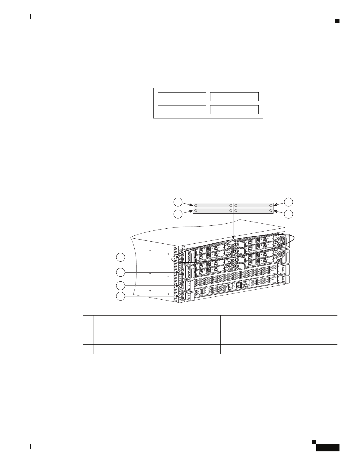
The Cisco ASR 1006 Router is designed with each slot numbered as shown in Figure 1-1.
OL-13208-03
Cisco ASR 1000 Series Aggregaion Services Routers Hardware Installation and Initial Configuration Guide
1-5
Page 26
Functional Overview
2
1
0
R1
R0
2
1
0
R1
R0
F1
STBY
ACTV
STAT
ASR1000-ESP10
PWR
STBY
ACTV
STAT
ASR1000-ESP10
PWR
F0
MIN
A
CO
MAJ
STBY
ACTV
STAT
ASR1000-RP1
PWR
CRIT
MIN
A
C
O
MAJ
STBY
ACTV
STAT
ASR1000-RP1
PWR
CRIT
0
A/L
C/A
0
A/L
C/A
0
A/
L
C
/A
0
A
/
L
C
/A
0
A
/
L
C
/A
0
A
/
L
C
/A
Chapter 1 Cisco ASR 1000 Series Routers Hardware Overview
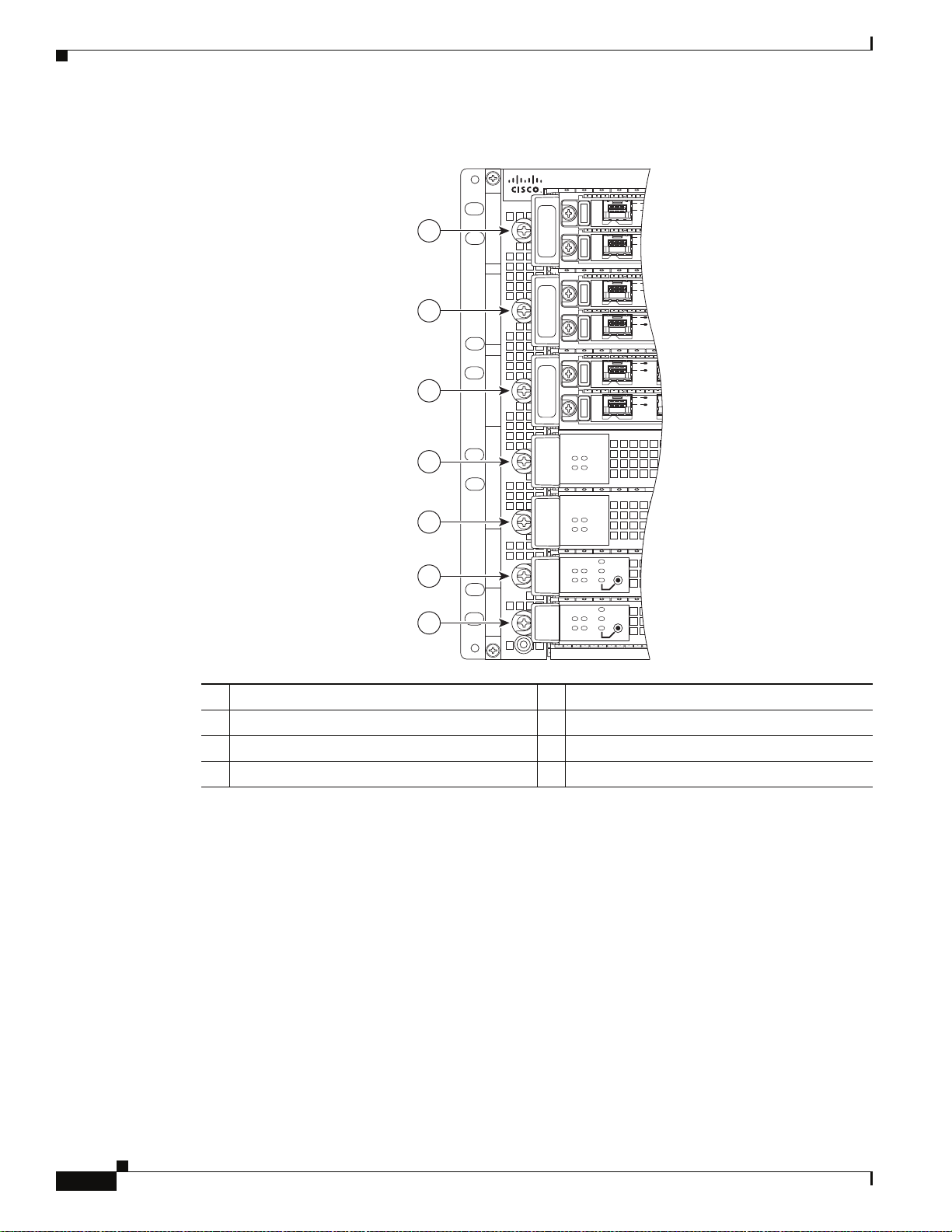
Figure 1-1 Cisco ASR 1006 Router — Slot Numbering
7
6
5
4
3
2
1
280033
1 Slot RP0 with ASR 1000 Series RP1 5 ASR 1000 Series SIP slot 0
2 Slot RP1 with ASR 1000 Series RP1 6 ASR 1000 Series SIP slot 1
3 Slot FP0 with ASR 1000 Series ESP 7 ASR 1000 Series SIP slot 2
4 Slot FP1 with ASR 1000 Series ESP
The Cisco ASR 1006 Router contains three Cisco ASR 1000 Series SPA Interface (SIP) supports four
subslots for the installation of SPAs.
1-6
Cisco ASR 1000 Series Aggregaion Services Routers Hardware Installation and Initial Configuration Guide
OL-13208-03
Page 27
Chapter 1 Cisco ASR 1000 Series Routers Hardware Overview
Figure 1-2 shows the Cisco ASR 1006 Router SPA subslot location.
Figure 1-2 Cisco ASR 1006 Router — ASR1000-SIP10 Subslots
Functional Overview
Front of SIP, horizontal chassis slots
SPA 0 SPA 1
Cisco ASR 1004 Router Slot Numbering
The Cisco ASR 1004 Router contains two Cisco ASR 1000 Series SPA Interface Processors (SIPs) and
supports four subslots for the installation of SPAs.
Figure 1-3 shows the Cisco ASR 1004 Router with modules and filler plates installed.
Figure 1-3 Cisco ASR 1004 Router —Front and Side View
4
3
SPA 2 SPA 3
6
5
S
A
/
U
C
T
A
T
/A
L
/
S
C
A
/A
L
/
C
A
/
L
/
C
A
L
/
A
1
A
0
/
C
A
/
L
/
C
A
L
/
A
1
0
A
/
C
A
/
L
/
C
A
L
/
A
1
A
0
/
C
A
/
L
/
C
A
L
/
A
1
0
OS
A
P
3C
O
PA-4X
S
3
S
A
2
/
U
C
T
A
T
A
/
L
/
S
C
A
L
/
OS
A
P
3C
O
-4X
PA
S
3
2
S
A
/
U
C
T
A
T
A
/
L
/
S
C
A
L
/
OS
A
3-P
C
O
4X
PA
S
3
S
2
/A
U
C
T
A
T
/A
L
/
S
C
A
L
/
OS
A
3-P
C
O
4X
PA
S
3
2
231508
7
8
S
A
U
C/
T
A
T
A
/
L
/
S
C
A
A
/
L
/
C
A
/
L
/
C
A
L
/
A
1
A
0
/
C
A
/
L
/
C
A
L
/
A
1
0
A
/
C
A
/
L
/
C
A
/L
A
1
A
0
/
C
A
/
L
/
C
A
L
/
A
1
0
S
A
PO
3
C
-4XO
PA
S
3
S
A
2
/
U
C
T
A
T
A
L
/
S
C/
A
L
/
S
A
PO
3
C
-4XO
PA
S
3
2
S
A
/
U
C
T
A
T
A
/
L
/
S
C
A
L
/
S
A
PO
3
C
O
X
-4
PA
S
3
S
2
/A
U
C
T
A
T
A
/
L
/
S
C
A
L
/
S
A
C3-PO
4XO
PA
S
3
2
2
1
1 Slot RP0 with ASR 1000 Series RP1 5 SPA subslot 2
2 Slot FP0 with ASR 1000 Series ESP10 6 SPA subslot 0
3 ASR 1000 Series SIP slot 0 7 SPA subslot 1
4 ASR 1000 Series SIP slot 1 8 SPA subslot 3
Cisco ASR 1002 Router Slot Numbering
The Cisco ASR 1002 Router contains one Cisco embedded ASR1002 -RP1 which is addressed as R0 and
one Cisco ASR1000-ESP5 or ASR1000-ESP10 forwarding processor in slot F0. The Cisco ASR 1002
Router consists of an embedded ASR1000-RP1 and embedded ASR1000-SIP10 board supporting three
half-height SPAs or 1half-height and one full-height SPA and one Cisco ASR1000-ESP5 forwarding
processor.
Cisco ASR 1000 Series Aggregaion Services Routers Hardware Installation and Initial Configuration Guide
OL-13208-03
X
U
A
N
CO
K
N
I
L
T
E
N
ER
H
ET
D
H
B
S
U
T
I
R
C
F
D
J
O
MA
CTV
A
K
S
I
AC
R
PW
T
A
T
S
SR
A
D
1
N
MI
0
Y
TB
S
-RP1
0
0
10
T
GM
ER
M
I
R
R
A
C
S
T
I
B
280312
1-7
Page 28
Functional Overview
Chapter 1 Cisco ASR 1000 Series Routers Hardware Overview
The SPA bays are bay 1, bay 2, and bay 3. The built-in 4xGE SPA ports are located in the SPA 0 location
and will be addressed as GE
0/0/x. The Cisco ASR 1002 Router provides a built-in 4-Gigabit Ethernet
interface and this SPA is physically located on the Cisco embedded ASR1000-RP1 board. The Cisco
ASR 1000 Series ESP card is located in slot 1 and labeled as FP0.
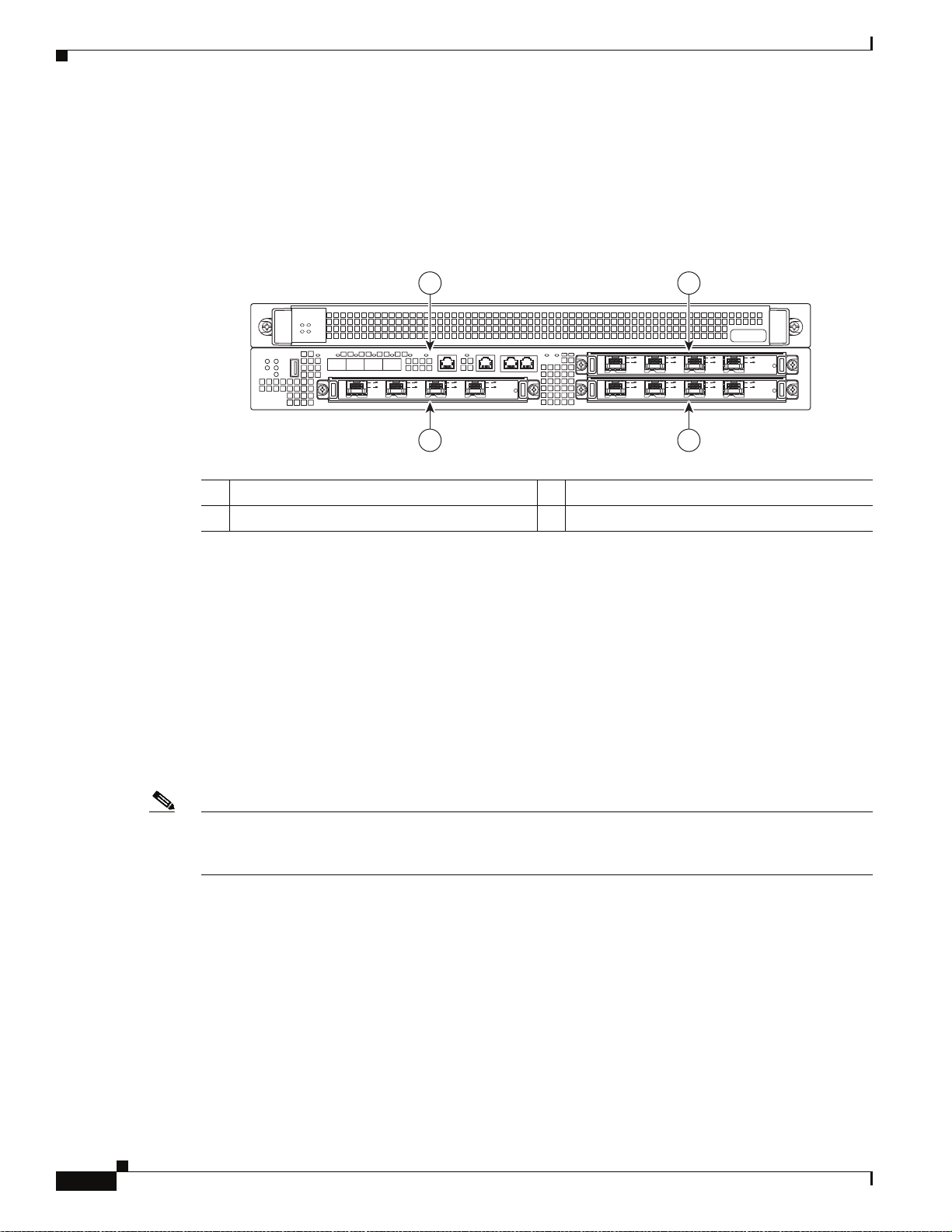
Figure 1-4 Cisco ASR 1002 Router Slot Numbering
ACTV
PWR
STBY
STAT
ASR1000-ESP10
ASR 1002
pwr
min
stat
maj
crit
1 Embedded route processor RP0 in subslot 0 3 Cisco SPA subslot 1
2 Cisco SPA subslot 2 4 Cisco SPA subslot 3
MAC Address Information
The Media Access Control (MAC) or hardware address is a standardized data link layer address that is
required for certain network interface types. These addresses are specific and unique to each port and
are not used by other devices in the network. The Cisco ASR 1000 Series Routers assign and control the
MAC addresses of its shared port adapters.
You can identify shared port adapter slots by using software commands. To display information about:
• All shared port adapter slots, use the show interfaces command.
QE0 QE1 BOOT
STAT
0
1
LINK PWR STATQE2 QE3
C
A
R
R
I
E
R
A
A
/
/
C
C
/L
A
A/L
1
2
/A
/A
C
C
A/L
S
U
L
AT
A/
T
S
SPA-4XOC3-POS
3
A
C/
L
A/
0
A
C/
L
A/
0
2
3
A
/
C
L
A/
1
2
A
/
C
/L
A
1
2
A
A
/
C
C/
L
/
A
A
/
C
L
A/
S
U
L
T
A
A/
T
S
SPA-4XOC3-POS
3
A
/
C
S
U
T
/L
A
A
T
S
SPA-4XOC3-POS
3
280369
4
1-8
• A specific shared port adapter slot, use the show interfaces command with the shared port adapter
type and slot number in the format show
interfaces port-adapter-type slot-number/port-number.
Note If you abbreviate the command (sh int) and do not specify shared port adapter type and slot number (or
arguments), the system interprets the command as show interfaces and displays the status of all shared
port adapters and ports.
The MAC addresses are assigned to the slots in sequence. For example, in the Cisco ASR 1006 Router,
the first address is assigned to slot 0 and the last address is assigned to slot 6. The actual MAC address
assignment is 16 MAC addresses per SPA slot for half-height SPAs and 64 per SPA slot for full-height
SPAs. Also, the Cisco ASR 1000 Series RP1 RP Management Ethernet port is assigned one MAC
address from the end of the pool and for a Cisco ASR 1006 Router with two Cisco ASR 1000 RP1s, each
ASR10000 RP1 is assigned one MAC address.
Using this address scheme, you can remove shared port adapters and insert them into other routers
without causing the MAC addresses to move around the network or be assigned to multiple devices.
Cisco ASR 1000 Series Aggregaion Services Routers Hardware Installation and Initial Configuration Guide
OL-13208-03
Page 29

Chapter 1 Cisco ASR 1000 Series Routers Hardware Overview
If the MAC addresses were stored on each shared port adapter, online insertion and removal would not
function because you could never replace one shared port adapter with an identical one; the MAC
addresses would always be different. Also, each time a shared port adapter was replaced, other devices
on the network would have to update their data structures with the new address. If the other devices did
not update quickly enough, the same MAC address could appear in more than one device at the same
time.
Note Storing the MAC addresses for every slot in one central location means the addresses stay with the
memory device on which they are stored.
Online Insertion and Removal
In the modular chassis configurations, most Cisco ASR 1000 Series Router field-replaceable units
(FRUs) support online insertion and removal (OIR). However, the removal of critical non-redundant
FRUs will result in service interruption.
Functional Overview
Note As you disengage the shared port adapter from the router, online insertion and removal (OIR)
administratively shuts down all active interfaces in the shared port adapter.
Online insertion and removal (OIR) allows you to install and replace shared port adapters while the
router is operating; you do not need to notify the software or shut down the system power, although you
should not run traffic through the shared port adapter you are removing while it is being removed. Online
insertion and removal is a method that is seamless to end users on the network, maintains all routing
information, and preserves sessions.
All SPA OIR events are independent of one another. An OIR event of a single SPA does not affect the
other SPAs in that ASR1000-SIP10 or any other system function.
Note The Cisco ASR 1002 Router differs from the Cisco ASR 1006 and Cisco ASR 1004 routers. The Cisco
ASR
1002 Router supports the Cisco embedded ASR1000-RP1 which is a combined route processor and
carrier card which are not field-replaceable units. The Cisco ASR1000-ESP5 or ASR1000-ESP10 are
field-replaceable units.
The following is a functional description of OIR for background information only; for specific
procedures for installing and replacing a shared port adapter in Cisco ASR 1000 Series Routers, refer to
the online configuration note for each shared port adapter.
When you remove or insert a shared port adapter in a Cisco ASR 1000 Series Router, the Control
Processor notifies the Cisco ASR1000-RP1, which in turn notifies the forwarding engine control
processor (FECP), and then performs as follows:
• Rapidly scans the midplane for configuration changes.
OL-13208-03
• Initializes all newly inserted shared port adapters, noting any removed interfaces and placing them
in the administratively shutdown state.
• Brings all previously configured interfaces on the shared port adapter back to the state they were in
when they were removed. Any newly inserted interfaces are put in the administratively shutdown
state, as if they were present (but not configured) at boot time. If a similar shared port adapter type
is reinserted into a slot, its ports are configured and brought online up to the port count of the
original SPA.
Cisco ASR 1000 Series Aggregaion Services Routers Hardware Installation and Initial Configuration Guide
1-9
Page 30

Chapter 1 Cisco ASR 1000 Series Routers Hardware Overview
Functional Overview
Environmental Monitoring and Reporting Functions
Environmental monitoring and reporting functions allow you to maintain normal system operation by
identifying and resolving adverse conditions prior to loss of operation.
Caution To prevent overheating the chassis, ensure that your system is drawing cool inlet air. Over temperature
conditions can occur if the system is drawing in the exhaust air of other equipment. Ensure adequate
clearance around the sides of the chassis so that cooling air can flow through the chassis interior
unimpeded and exhaust air exits the chassis and is not drawn into the inlet vent of another device.
Environmental Monitoring
The environmental monitoring functions use sensors to monitor the temperature of the cooling air as it
moves through the chassis.
The local power supplies provide the ability to monitor:
• Input and output voltage
• Output current
• Outlet temperature
The router is expected to meet the following environmental operating conditions:
• Operating Temperature Nominal: 5° to 40°C
• Operating Temperature Short Term: 5° to 55°C
• Operating Humidity Nominal: 5% to 85% non-condensing
• Operating Humidity Short Term: 5% to 90% non-condensing
• Operating Altitude: 198 to 13,200 feet (60 to 4000 meters)
• DC Input Range: –40.5 to –72 VDC
• AC Input Range: 85 to 264 VAC
If the air temperature exceeds a defined threshold, the system controller displays warning messages on
the console terminal, and if the temperature exceeds the shutdown threshold, the system controller shuts
down the system.
In addition, the power supplies monitor internal power supply temperatures and voltages. A power
supply is either within tolerance (normal) or out of tolerance (critical). If an internal power supply
temperature or voltage reaches a critical level, the power supply shuts down without any interaction with
the system processor.
The environmental monitoring functions use the following levels of status conditions to monitor the
system:
• Normal—All monitored parameters are within normal tolerances.
1-10
• Warning—The system has exceeded a specified threshold. The system continues to operate, but
operator action is recommended to bring the system back to a normal state.
• Critical—An out-of-tolerance temperature or voltage condition exists. The system continues to
operate; however, the system is approaching shutdown. Immediate operator action is required.
Cisco ASR 1000 Series Aggregaion Services Routers Hardware Installation and Initial Configuration Guide
OL-13208-03
Page 31

Chapter 1 Cisco ASR 1000 Series Routers Hardware Overview
• Shutdown—The processor has detected a temperature condition that could result in physical damage
to system components and has disabled DC power to all internal components. This condition
requires immediate operator action. All DC power remains disabled until you toggle the power
switch. Before any shutdown, the system logs the status of monitored parameters in NVRAM so you
can retrieve it later to help determine the cause of the problem.
• Power supply shutdown—The power supply detected an internal out-of-tolerance overvoltage,
overcurrent, or temperature condition and shut itself down. All DC power remains disabled until you
toggle the power switch.
Fan Failures
When the system power is on, all fans should be operational. The system continues to operate if a fan
fails. When a fan fails, the system displays the following message:
router: 00:03:46:%ENVM-3-BLOWER:Fan 2 may have failed
If the air temperature exceeds a defined threshold, the system controller displays warning messages on
the console terminal, and if the temperature exceeds the shutdown threshold, the system controller shuts
down the system.
If the system does shut down because the temperature exceeded the shutdown threshold, the system
displays the following message on the console screen and in the environment display when the system
restarts:
Queued messages:
%ENVM-1-SHUTDOWN: Environmental Monitor initiated shutdown
Functional Overview
Reporting Functions
The chassis manager on the forwarding engine control processor manages the local resources of the
forwarding processor. It manages the ESI (Enhanced Serdes Interconnect) which are the datapath links
on the midplane connecting the Cisco ASR 1000 Series RP1s, SIPs, and standby ESP modules to the
active Cisco ASR 1000 Series Embedded Services Processor. It communicates with the chassis manager
on the Cisco ASR 1000 Series Route Processor 1 to report the status and health, including detected
hardware failures, ESI status, software process status, and the state of thermal sensors.
The Cisco ASR 1000 Series Routers display warning messages on the console if chassis
interface-monitored parameters exceed a desired threshold. You can also retrieve and display
environmental status reports with the show environment all, show version, show inventory, show
platform, and show diag commands. Parameters are measured and reporting functions are updated
every 60 seconds. A brief description of each of these commands follows.
Note The example outputs displayed in this section are from a Cisco ASR 1004 Router. Similar output
displays for all Cisco ASR 1000 series routers.
OL-13208-03
Cisco ASR 1000 Series Aggregaion Services Routers Hardware Installation and Initial Configuration Guide
1-11
Page 32

Functional Overview
Chapter 1 Cisco ASR 1000 Series Routers Hardware Overview
Example 1-1 Show Environment All Command
Router#show environment
% Incomplete command.
Router#show environment all
Sensor List: Environmental Monitoring
Sensor Location State Reading
V1: VMA F0 Normal 1791 mV
V1: VMB F0 Normal 1196 mV
V1: VMC F0 Normal 1191 mV
V1: VMD F0 Normal 1093 mV
V1: VME F0 Normal 996 mV
V1: 12v F0 Normal 11894 mV
V1: VDD F0 Normal 3261 mV
V1: GP1 F0 Normal 900 mV
V2: VMA F0 Normal 3286 mV
V2: VMB F0 Normal 2495 mV
V2: VMC F0 10% high 1796 mV
V2: VMD F0 Normal 1093 mV
V2: VME F0 Normal 996 mV
V2: VMF F0 Normal 996 mV
V2: 12v F0 Normal 11850 mV
V2: VDD F0 Normal 3261 mV
V2: GP1 F0 10% high 898 mV
Temp: Inlet F0 Normal 29 Celsius
Temp: Asic1 F0 Normal 47 Celsius
Temp: Exhaust1 F0 Normal 36 Celsius
Temp: Exhaust2 F0 Normal 36 Celsius
Temp: Asic2 F0 Normal 43 Celsius
V1: VMA 0 Normal 1093 mV
V1: VMB 0 Normal 1196 mV
V1: VMC 0 Normal 1494 mV
V1: VMD 0 Normal 1791 mV
V1: VME 0 Normal 2490 mV
V1: VMF 0 Normal 3291 mV
V1: 12v 0 Normal 11894 mV
V1: VDD 0 Normal 3266 mV
V1: GP1 0 Normal 747 mV
V1: GP2 0 Normal 898 mV
V2: VMA 0 20% low 0 mV
V2: VMB 0 Normal 1201 mV
V2: VMC 0 20% low 0 mV
V2: VMD 0 20% low 0 mV
V2: VME 0 20% low 0 mV
V2: VMF 0 20% low 0 mV
V2: 12v 0 Normal 11909 mV
V2: VDD 0 Normal 3271 mV
V2: GP2 0 Normal 903 mV
Temp: Left 0 Normal 25 Celsius
Temp: Center 0 Normal 26 Celsius
Temp: Asic1 0 Normal 36 Celsius
Temp: Right 0 Normal 23 Celsius
PEM Iout P0 Normal 17 A
PEM Vout P0 Normal 12 V AC
PEM Vin P0 Normal 115 V AC
Temp: PEM P0 Normal 27 Celsius
Temp: FC P0 Fan Speed 65% 26 Celsius
Temp: FM P1 Normal 24 Celsius
Temp: FC P1 Fan Speed 65% 26 Celsius
V1: VMA R0 Normal 1098 mV
V1: VMB R0 Normal 3295 mV
V1: VMC R0 Normal 2495 mV
1-12
Cisco ASR 1000 Series Aggregaion Services Routers Hardware Installation and Initial Configuration Guide
OL-13208-03
Page 33

Chapter 1 Cisco ASR 1000 Series Routers Hardware Overview
V1: VMD R0 Normal 1791 mV
V1: VME R0 Normal 1499 mV
V1: VMF R0 Normal 1201 mV
V1: 12v R0 Normal 11938 mV
V1: VDD R0 Normal 3261 mV
V1: GP1 R0 Normal 903 mV
V1: GP2 R0 Normal 1242 mV
Temp: CPU R0 Normal 33 Celsius
Temp: Outlet R0 Normal 32 Celsius
Temp: Inlet R0 Normal 26 Celsius
Temp: Asic1 R0 Normal 32 Celsius
Example 1-2 Show Version Command
The show version command displays the system hardware configuration, software version, and names
and sources of configuration files and boot images.
Following is sample output of the show version command:
Router# show version
Cisco IOS Software, IOS-XE Software (PPC_LINUX_IOSD-ADVENTERPRISEK9-M), Version
12.2(33)XNA, RELEASE SOFTWARE
Technical Support: http://www.cisco.com/techsupport
Copyright (c) 1986-2008 by Cisco Systems, Inc.
Compiled Thu 01-May-08 00:29 by mcpre
Cisco IOS-XE software, Copyright (c) 1986-2008 by Cisco Systems, Inc.
Functional Overview
All rights reserved. Certain components of Cisco IOS-XE software are
licensed under the GNU General Public License ("GPL") Version 2.0. The
software code licensed under GPL Version 2.0 is free software that comes
with ABSOLUTELY NO WARRANTY. You can redistribute and/or modify such
GPL code under the terms of GPL Version 2.0. For more details, see the
documentation or "License Notice" file accompanying the IOS-XE software,
or the applicable URL provided on the flyer accompanying the IOS-XE
software.
A summary of U.S. laws governing Cisco cryptographic products may be found at:
http://www.cisco.com/wwl/export/crypto/tool/stqrg.html
If you require further assistance please contact us by sending email to
export@cisco.com.
cisco ASR1004 (RP1) processor with 757182K/6147K bytes of memory.
2 Packet over SONET interfaces
32768K bytes of non-volatile configuration memory.
2097152K bytes of physical memory.
439807K bytes of eUSB flash at bootflash:.
39004543K bytes of SATA hard disk at harddisk:.
Configuration register is 0x0
Example 1-3 Show Inventory Command
The show inventory command displays an extended report that includes the product inventory listing of
all Cisco products installed in the networking device.
Following is sample output of the show inventory command:
OL-13208-03
Router#show inventory
NAME: "Chassis", DESCR: "Cisco ASR1004 Chassis"
Cisco ASR 1000 Series Aggregaion Services Routers Hardware Installation and Initial Configuration Guide
1-13
Page 34

Functional Overview
Chapter 1 Cisco ASR 1000 Series Routers Hardware Overview
PID: ASR1004 , VID: V00, SN:
NAME: "module 0", DESCR: "Cisco ASR1000 SPA Interface Processor 10"
PID: MCP-CC , VID: V00, SN: JAB1104064G
NAME: "SPA subslot 0/1", DESCR: "2-port OC3/STM1 POS Shared Port Adapter"
PID: SPA-2XOC3-POS , VID: V01, SN: JAB1006095Z
NAME: "subslot 0/1 transceiver 0", DESCR: "OC3 SR-1/STM1 MM"
PID: N/A , VID: , SN: 2008692
NAME: "SPA subslot 0/2", DESCR: "4-port T3/E3 Serial Shared Port Adapter"
PID: SPA-4XT3/E3 , VID: V01, SN: JAB09210247
NAME: "module R0", DESCR: "Cisco ASR1000 Route Processor 1"
PID: ASR1000-RP1 , VID: V00, SN: JAB110200CQ
NAME: "module F0", DESCR: "Cisco ASR1000 Embedded Services Processor, 10Gbps"
PID: ASR1000-ESP10 , VID: V00, SN: JAB111101A1
NAME: "Power Supply Module 0", DESCR: "Cisco ASR1004 AC Power Supply"
PID: ASR1004-PWR-AC , VID: V00, SN: ART1103K00C
NAME: "Fan Module 1", DESCR: "Cisco ASR1004 Fan Module"
PID: ASR1004-FAN , VID: V00, SN: ART1052L01U
Example 1-4 Show Platform Command
The show platform command displays the output of the current wait policy for each type of connection,
as well as any information on the currently configured banners.
Following is sample output of the show platform command:
Router#show platform
Chassis type: ASR1004
Slot Type State Insert time (ago)
--------- ------------------- --------------------- ----------------0 MCP-CC ok 16:20:27
0/1 SPA-2XOC3-POS ok 16:18:49
0/2 SPA-4XT3/E3 ok 16:18:56
R0 ASR1000-RP1 ok, active 16:20:27
F0 ASR1000-ESP10 ok, active 16:20:27
P0 ASR1004-PWR-AC ok 16:19:27
P1 ASR1004-FAN ok 16:19:27
Slot CPLD Version Firmware Version
--------- ------------------- --------------------------------------0 07091401 12.2(33r)XN1
R0 0706210B 12.2(33r)XN1
F0 07051650 12.2(33r)XN1
Example 1-5 Show Diag Command
1-14
The show diag slot R0 eeprom detail command displays the configuration hardware information
including DRAM and Static RAM (SRAM) on line cards. To display more details than the normal show
diag command output, use show diag [slot-number] [details].
Following is sample output of the show diag slot R0 eeprom detail command:
Cisco ASR 1000 Series Aggregaion Services Routers Hardware Installation and Initial Configuration Guide
OL-13208-03
Page 35

Chapter 1 Cisco ASR 1000 Series Routers Hardware Overview
Router#show diag slot R0 eeprom detail
Slot R0 EEPROM data:
EEPROM version : 4
Compatible Type : 0xFF
Controller Type : 1460
Hardware Revision : 4.7
PCB Part Number : 73-10253-04
Board Revision : 03
Deviation Number : 0-0
Fab Version : 04
PCB Serial Number : JAB110200CQ
RMA Test History : 00
RMA Number : 0-0-0-0
RMA History : 00
Top Assy. Part Number : 68-2625-04
Product Identifier (PID) : ASR1000-RP1
CLEI Code : UNASSIGNED
Version Identifier (VID) : V00
Manufacturing Test Data : 00 00 00 00 00 00 00 00
Field Diagnostics Data : 00 00 00 00 00 00 00 00
Asset ID : AAAAAAAAAAAAAAAAAAAAAAAAAAAAAAAA
Cisco Product Identification Standard
Cisco Product Identification Standard
This section describes the Cisco products and services product identification standard. This feature
provides you with the ability to effectively integrate and manage Cisco products in your network and
business operations.
OL-13208-03
Cisco ASR 1000 Series Aggregaion Services Routers Hardware Installation and Initial Configuration Guide
1-15
Page 36

Cisco Product Identification Standard
Unique Device Identifier
The Unique Device Identifier (UDI) is the Cisco product identification standard for hardware products.
A product identification standard removes barriers to enterprise automation and can help you reduce
operating expenses.
The UDI provides a consistent electronic, physical, and associated business-to-business information
product identification standard.
The UDI is a combination of five data elements. Table 1-2 lists the UDI elements.
Ta b l e 1-2 Cisco UDI Elements
Chapter 1 Cisco ASR 1000 Series Routers Hardware Overview
UDI Data Element
Electronic
Visibility
Physical
Visibility
Description
PID Yes Ye s Product ID, also known as product name, model
name, product number
VID Yes Ye s Ve r s i o n I D
SN Yes Ye s Serial number, the unique instance of the PID (see
Figure 1-5, Figure 1-7, and Figure 1-6 in the next
section for location of the serial number label)
Entity Name Ye s No Type, such as chassis, slot, or power supply
Product Description Yes No Additional product information
The combination of serial number and product ID (PID) is unique and consistent across all Cisco
products. The PID that is coded on hardware is called a base product identifier.
Additional orderable PIDs may be associated to a base PID. For instance, an orderable PID may describe
a packaging configuration for a product or a bundled group of products sold, tested, and shipped
together. Specific unique device identifier (UDI) benefits include the following:
• Identifies:
–
Individual Cisco products in your networks
–
PIDs and SNs for service and replaceable products
–
VIDs for product version visibility
1-16
• Facilitates discovery of products subject to recall or upgrade
• Enhances inventory automation of Cisco products
The Cisco product identification standard provides the following features:
• Version visibility—Cisco continuously improves products through feature additions. Product
changes are indicated by incrementing the version ID (VID), which provides version visibility to
help you understand and manage product changes. The VID management ensures consistency of
changes from product to product.
• Operating expense reduction— The Cisco UDI provides accurate and detailed network inventory
information; identifying each Cisco product in a network element through a standard interface.
Cisco operating systems can view and use this data, allowing you to automate your electronic
inventory.
Cisco ASR 1000 Series Aggregaion Services Routers Hardware Installation and Initial Configuration Guide
OL-13208-03
Page 37

Chapter 1 Cisco ASR 1000 Series Routers Hardware Overview
• Consistency across product layers—The UDI is designed into hardware products and cannot
overwritten in error. Operating and management systems discover the UDI through standard
interfaces and display the UDI in standard outputs. Standard interfaces include the IETF standard
ENTITY-MIB.
Note Go to the following URL for complete information on the product identification standard:
http://www.cisco.com/go/udi/
Serial Number Label Location
This section contains graphics of each chassis showing the location of the serial number label.
Cisco Product Identification Standard
OL-13208-03
Cisco ASR 1000 Series Aggregaion Services Routers Hardware Installation and Initial Configuration Guide
1-17
Page 38

Cisco Product Identification Standard
Figure 1-5 shows the serial number location for the Cisco ASR 1006 Router.
Figure 1-5 Cisco ASR 1006 Router Serial Number Label Location
Chapter 1 Cisco ASR 1000 Series Routers Hardware Overview
SN: XXXNNNNXXXX
280157, 781-00578-01
1-18
Cisco ASR 1000 Series Aggregaion Services Routers Hardware Installation and Initial Configuration Guide
OL-13208-03
Page 39
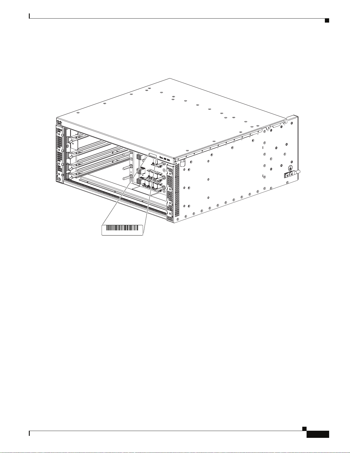
Chapter 1 Cisco ASR 1000 Series Routers Hardware Overview
Figure 1-6 shows the serial number label location for the Cisco ASR 1004 Router.
Figure 1-6 Cisco ASR 1004 Router Serial Number Label Location
Cisco Product Identification Standard
202416, 781-00564-01
SN: XXXNNNNXXXX
OL-13208-03
Cisco ASR 1000 Series Aggregaion Services Routers Hardware Installation and Initial Configuration Guide
1-19
Page 40

Cisco Product Identification Standard
Figure 1-7 shows the serial number label location for the Cisco ASR 1002 Router.
Figure 1-7 Cisco ASR 1002 Router Serial Number Label Location
Chapter 1 Cisco ASR 1000 Series Routers Hardware Overview
SN: XXXNNNNXXXX
280158, 781-00579-01
1-20
Cisco ASR 1000 Series Aggregaion Services Routers Hardware Installation and Initial Configuration Guide
OL-13208-03
Page 41

CHAPTER
2
Cisco ASR 1000 Series Routers Components
The Cisco ASR 1000 Series Routers contain the following components:
• Cisco ASR 1000 Series Route Processor, page 2-1
• Cisco ASR 1000 Series Embedded Services Processors, page 2-9
• Cisco ASR 1000 Series SPA Interface Processor, page 2-13
• Cisco ASR 1000 Series Router Power Supplies, page 2-16
Note Throughout this document, the term slot refers to a Cisco ASR 1000 Series Router chassis slot. The
Cisco ASR 1000 Series Route Processor 1, Cisco ASR 1000 Series Embedded Services Processor, and
Cisco ASR 1000 Series SPA Interface Processor (SIP), and power supplies plug into these slots. Shared
port adapters plug into SIP bays.
Cisco ASR 1000 Series Route Processor
The Cisco ASR 1000 Series Route processor is the central network clocking card and runs the network
operating system, BINOS kernel plus IOSD (IOS daemon). The Cisco ASR1000-RP1 is responsible for:
• Selection of the active Cisco ASR 1000 Series Route Processor and the Cisco ASR 1000 Series
Embedded Services Processor and notification of the Cisco ASR 1000 Series SPA Interface
Processor of these events.
• All the control processors communicating and performing packet processing on packets punted to it
by the Cisco ASR 1000 Series Embedded Services Processors (ESP).
The Cisco ASR 1000-RP1 has LED status indicators, an RJ-45 plug for DTI and BITS timing reference,
and two USB ports which can be used with smart cards for secure key distribution.
Specific system tasks performed by the Cisco ASR 1000 Series Route Processor include the following:
• Runs the router control plane, including network control packets, and connection setup
• User interfaces: 10/100/1000 Management Ethernet, CON/AUX, USB
• Active and standby Cisco ASR 1000 Series RP1 and Cisco ASR 1000 Series Embedded Services
Processor master and standby synchronization (Tasks include switchover from failing master to
standby.)
• Code storage, management, and upgrade.
OL-13208-03
Cisco ASR 1000 Series Aggregation Services Routers Hardware Installation and Initial Configuration Guide
2-1
Page 42

Cisco ASR 1000 Series Route Processor
• Downloading operational code for SIPs and Cisco ASR 1000 Series Embedded Services Processor
over Ethernet out of band channel (EOBC), which is used for communication between the control
processors on the Cisco ASR 1000 Series Routers
• Command line interface (CLI), alarm, network management, logging, and statistics aggregation
• Chassis management
• Ethernet out-of-band management
• Punt path processing for packets not supported by the embedded services processors
Cisco ASR 1000 Series Route Processor Features
The Cisco ASR1000-RP1 route processors receive and transmit all network packets through the active
embedded services processors. The Cisco ASR1000-RP1:
• Provides a configuration repository along with a hard disk drive (optionally a solid-state drive) for
logging system statistics, records, events, errors, and dumps (for both the Cisco ASR 1006 Router
and Cisco ASR 1004 Router).
• Provides the management interfaces of the platform including Dual Asynchronous
Receiver/Transmitter (DUART) that is used for the CON and AUX serial ports. The MGMT Ethernet
(ENET) management ports, CLI, status indicators, BITS interface, reset switch, Audible Cutoff
(ACO) button, and USB ports for secure keys.
• Provides chassis management (environmental)
Chapter 2 Cisco ASR 1000 Series Routers Components
• Is a field-replaceable units (FRU) with online insertion and removal (OIR)., except for the built-in
RP1 on the Cisco ASR1002 router
• Provides non-volatile storage for the system used as the image and configuration repository along
with the logger for system statistics, records, events, errors, and dumps.
• Is responsible for the chassis management including activation and initialization of the other cards,
selection or switchover of active versus standby cards, image management and distribution, logging
facilities, distribution of user configuration information, and alarm control.
• Provides control signals and Ethernet out of band channel (EOBC) for the two Cisco ASR 1000
Series Embedded Services Processors and one other Cisco ASR 1000 Series Route Processor 1.
• Includes control signals for monitoring the health of power entry modules, shutting down the power
and driving alarm relays located on the power entry modules.
• The Cisco ASR 1000 Series RP1 module can be configured with either a 40 GB or a 32 GB disk.
The Cisco ASR 1000 Series route processor module consists of a front panel label for indicator and
control functions and a separate label for the I/O connectors. The Cisco ASR1000-RP1 model number
labeling is located next to the left card module handle. The modules also contain card handles to assist
in insertion or removal of the module.
2-2
Cisco ASR 1000 Series Aggregation Services Routers Hardware Installation and Initial Configuration Guide
OL-13208-03
Page 43

Chapter 2 Cisco ASR 1000 Series Routers Components
01
DISK
BF
USB
HD
MIN
ACO
MAJ
STBY
ACTV
STAT
ASR1000-RP1
PWR
CRIT
CARRIER
LINK
MGMT ETHERNET
BITS CON AUX
Figure 2-1 shows the Cisco ASR 1000 Series Route Processor faceplate.
Figure 2-1 Cisco ASR Series 1000 Route Processor Faceplate LEDs and Connectors
Cisco ASR 1000 Series Route Processor
1
2
3
280078
5
4
1 Internal hard drive LED 4 USB 0, USB 1 connector
2 External USB Flash LED 5 ASR1000 RP1 LEDs
3 Internal USB bootflash LED
Figure 2-2 shows the Cisco ASR1000-RP1 with faceplate connectors.
Figure 2-2 Cisco ASR Series 1000 Route Processor Connectors
1 2 3 4 5 6
OL-13208-03
1 CARRIER LED 4 MGMT Ethernet connector
2 BITS connector 5 CON connector
3 LINK LED 6 AUX connector
Cisco ASR 1000 Series Aggregation Services Routers Hardware Installation and Initial Configuration Guide
280079
2-3
Page 44

Cisco ASR 1000 Series Route Processor
Table 2-1 lists the Cisco ASR 1000 Series Route Processor LEDs and behaviors.
Ta b l e 2-1 Cisco ASR 1000 Series Route Processor LEDs
LED Label LED Color —State Behavior Description
PWR Power Solid green All power requirements are within
STAT System status Solid green Cisco IOS software has successfully
ACTV Active Green Lit when the Cisco ASR 1000 Series RP1
STBY Standby Yellow Lit when the Cisco ASR1000 Series RP1 is
CRIT Critical Solid Red Critical alarm indicator or during boot
MAJ Major Solid Red Major alarm indicator. For example:
MIN Minor Amber Minor alarm indicator. Ambient air tem-
DISK HD Internal hard drive
DISK USB External USB Flash
DISK BF Internal USB
CARRIER LED Off Out of service or not configured.
LINK 10/100/1000 RJ-45
LED
LED
bootflash LED
Interface LED
Chapter 2 Cisco ASR 1000 Series Routers Components
specification
Off Off, the router is in standby mode.
booted.
Yellow BootROM has successfully loaded.
Red System failure or during boot process.
is active.
the standby processor.
process. An example: the ambient air temperature is above 60ºC and will begin
shutdown in 5 minutes.
Ambient air temperature is beyond short
term operating range of 55ºC. System will
shut down above 60ºC.
perature is beyond normal operating range
of 40ºC. For example: if the RP software
determines that an unknown card has been
installed or if the card has failed, the card
can power it off or set a minor alarm.
Flashing Green Activity indicator.
Off No activity.
Flashing Green Activity indicator.
Off No activity.
Flashing Green Activity indicator.
Off No activity.
Solid Green In frame and working properly.
Amber Fault or loop condition exists.
Solid Green Link with no activity.
Flashing Green Link with Activity.
Off No link.
2-4
Cisco ASR 1000 Series Aggregation Services Routers Hardware Installation and Initial Configuration Guide
OL-13208-03
Page 45

Chapter 2 Cisco ASR 1000 Series Routers Components
How the Cisco ASR1000-RP1 Alarm LEDs Work
The Cisco ASR1000-RP1 faceplate displays the CRIT, MAJ, and MIN alarm indicator LEDs. A female
DB-25 connector on the power supply faceplate enables you to attach an external alarm monitoring
facility to the router. See
A-4.
The alarm signals sent to this DB-25 connector are identical in function to those sent to the system LEDs
on the Cisco ASR1000-RP1. Each alarm consists of three contact pins that are switched when an alarm
becomes active which causes a corresponding contact closure between the DB-25 connector pins.
Thus, a critical, major, or minor alarm condition detected in the router can trigger a simultaneous fault
indication in some of the following ways:
• System alarm LEDs—The three system alarm LEDs on the Cisco ASR1000-RP1 faceplate
constitute the standard method of alarm notification in the router. These LEDs indicate router status
at all times, but you must directly observe these LEDs to become aware of a router alarm condition.
• External alarm monitoring facility—By equipping your router with a telco-style external alarm
monitoring facility, you can provide a more physical indication of router status. A visual alarm,
however, can be reset only by resolving the problem that caused the alarm condition.
For example, the same alarm signal that illuminates one of the three system alarm LEDs on the Cisco
ASR1000-RP1 faceplate for a critical, major, or minor alarm condition is also sent to the DB-25
connector by means of an associated alarm relay in the Cisco ASR1000-RP1.
Cisco ASR 1006 Router DB-25 Pinout Assignments for Alarm Relays, page
Cisco ASR 1000 Series Route Processor
An external alarm monitoring facility uses this signal to activate a visible alarm (such as a flashing
light) or an audible alarm that immediately alerts site personnel to the existence of a router alarm
condition.
An external audible alarm can be reset by clearing the condition that caused the alarm or by pressing the
Audible Cutoff (ACO) button on the Cisco ASR1000-RP1. An audible alarm can be sounded to
immediately alert you of an alarm condition in the router. An audible alarm generated by the system
continues to sound until you either clear the alarm condition itself or press the ACO button to silence the
alarm. Pressing this button does not resolve the alarm condition.
Table 2-2 lists the Cisco ASR 1000 Series Route Processors connectors and description.
Ta b l e 2-2 Cisco ASR 1000 Series Route Processor Connectors
Label Ty pe Description
ACO Audible Cutoff button When you press this button, an interrupt is
generated informing software that the audible alarm
relays will be disabled. This interrupt generates to
both processors.
0 USB0 interface Side-by-side USB connector used with memory
sticks or smart cards for secure key distribution
1 USB1 interface Side-by-side USB connector used with memory
sticks or smart cards for secure key distribution
BITS RJ-45 connector Indicates BITS timing reference.
MGMT
ETHERNET
One RJ-45 jack for
copper Ethernet
Management Port
The route processor has an ENET port with a RJ-45
connector to attach a management device or
network for network management.
OL-13208-03
Cisco ASR 1000 Series Aggregation Services Routers Hardware Installation and Initial Configuration Guide
2-5
Page 46

Cisco ASR 1000 Series Route Processor
Table 2-2 Cisco ASR 1000 Series Route Processor Connectors (continued)
Label Type Description
CON One RJ-45 for CON/AUX Console port used to connect to a terminal.
AUX One RJ-45 for CON/AUX Auxiliary port used for remote management
The Cisco ASR 1000 Series Route Processor meets the following requirements:
• Supports up to 4GB(bytes) of memory with single-bit error correction and multi-bit error detection
except for the built-in RP1 on the Cisco ASR1002 router
• Supports On-board Failure Logging (OBFL) with 2MB of memory
• Supports the Cisco ASR 1000 Series Router system architecture and midplane
• Enhanced Serdes Interconnect (ESI) at 11.5Gbps.
• Gigibit Ethernet switches for EOBC communication and boot-up of the Cisco ASR 1000 Series SPA
Interface (SIP) and Cisco ASR 1000 Series Embedded Services Processor.
Chapter 2 Cisco ASR 1000 Series Routers Components
purposes.
• Runs Cisco IOS network control plane (routing protocol, connections setup)
• Cisco IOS punt packet forwarding
• Active/Standby Cisco ASR 1000 Series Route Processor 1 and Cisco ASR 1000 Series Embedded
Services Processor selection
• Code storage and download operational code to Cisco ASR 1000 Series Embedded Services
Processor and Cisco ASR 1000 Series SPA Interface (SIP)
• Bulk storage: by default, it comes with a 40GB hard disk drive (HDD). A 32GB solid state disk drive
(SSD optional) can also be configured.
• 2 MB upgradeable BootROM, 1GB embedded USB memory (eUSB), except for the built-in RP1 on
the Cisco ASR1002 router.
• Comes with 2GB of DRAM as default and can be upgradeable to 4 GB DRAM.
• Front panel support: Console, 10/100 Management port, two USB ports, CON port, and AUX port.
The two serial ports can run up to 115.2kbps with hardware flow control. One port is used as the
CONSOLE port for secure configuration and status display. The default BAUD rate for the CONSOLE
port should be set at 9600 BAUD. The console port is an asynchronous serial port; any devices connected
to this port must be capable of asynchronous transmission.
The auxiliary port connects a modem or other DCE device (such as a CSU/DSU or other router) to allow
remote service and dial backup access to the system. Both the console and auxiliary ports are
asynchronous serial ports; any devices connected to these ports must be capable of asynchronous
transmission.The AUX port is a diagnostics access port.
Cisco Embedded ASR1000-RP1 for Cisco ASR 1002 Router
The route processor for the Cisco ASR 1002 Router is integrated in the chassis and supports all the
typical customer management interfaces such as the Ethernet network management port and console and
auxiliary serial ports of the route processor for the Cisco ASR 1006 and ASR 1004 routers. It also has
LED status indicators, an RJ-45 plug for a BITS timing reference and one USB ports which can be used
with smart cards for secure key distribution or for image or configuration file updates.
the Cisco ASR1000-RP1 LEDs for the Cisco ASR1002 router.
Cisco ASR 1000 Series Aggregation Services Routers Hardware Installation and Initial Configuration Guide
2-6
Figure 2-3 shows
OL-13208-03
Page 47

Chapter 2 Cisco ASR 1000 Series Routers Components
Figure 2-3 Embedded Cisco ASR1000-RP1 LEDs
The embedded route processors for the Cisco ASR 1002 Router provides connection for one SPA bay
and the circuitry for the a built-in 4xGE SPA.
The Cisco route processor for ASR 1002 Router meets the requirements of route processors for the
Cisco
ASR 1006 and the Cisco ASR 1004 routers; except for the following deviations:
• No SATA hard drive supported. Bulk file storage is on a large fixed eUSB device (up to 8GB (bytes)
supported).
• No support for redundant route processors.
ASR 1002
pwr
stat
Cisco ASR 1000 Series Route Processor
min
maj
crit
250603
• Hardware memory and storage options (such as DRAM) are not field upgradeable.
• Network clock changes. No second BITS clock input supported.
• The LED order is from top to bottom on the route processor is MIN, MAJ, CRIT.
Table 2-3 lists the Cisco embedded ASR1000-RP1 LEDs and behaviors.
Ta b l e 2-3 Cisco Embedded ASR1000-RP1 LEDs in the Cisco ASR 1002 Router
LED Label LED Color —State Behavior Description
PWR Power Solid green All power requirements are within
specification
Off Off, the router is in standby mode.
STAT System status Solid green Cisco IOS has successfully booted.
Yellow ROMMON is running or when the Process
Manager declares that a critical ASR 1000
Series RP1 process is not running
Red System failure or powering up.
MIN Minor Amber Minor alarm indicator.
MAJ Major Red Major alarm indicator.
CRIT Critical Red Critical alarm indicator.
BOOT eUSB0 FLASH
(BootDisk
Flashing Green Activity indicator.
Off No activity.
CARRIER Off Out of service or not configured.
Green In frame and working properly.
Amber Fault or loop condition.
OL-13208-03
Cisco ASR 1000 Series Aggregation Services Routers Hardware Installation and Initial Configuration Guide
2-7
Page 48

Cisco ASR 1000 Series Route Processor
Table 2-3 Cisco Embedded ASR1000-RP1 LEDs (continued) in the Cisco ASR 1002 Router
LED Label LED Color —State Behavior Description
LINK 10/100 /1000 RJ-45
4 LEDs Built-in SPA SFP
PWR Carrier card power Green All carrier card requirements are within
STAT Carrier card status Green Only when the SPA drivers have started and
Interface LED
port status
Chapter 2 Cisco ASR 1000 Series Routers Components
Green Link with no activity.
Flashing Green Link with activity.
Off No link.
Off Port is not enabled.
Amber Port enabled but there is a problem with the
Ethernet link.
Green Port enabled, valid Ethernet link
specification.
are running and all critical processes are
running
Yellow When ROMMON is running and during the
download and boot of the operating system
Red A fault is detected or the card is powering
up.
Table 2-4 lists the Cisco embedded ASR1000-RP1in the Cisco ASR 1002 Router connectors and
description.
Ta b l e 2-4 Cisco Embedded ASR1000-RP1 Connectors
Label Ty pe Description
BITS Standard E1/T1 RJ-45
Indicates BITS timing references.
connector
MGMT
One RJ-45 jack for
copper Ethernet
Management Ethernet
The route processor has an ENET port with a RJ-45
connector to attach a management device or network
for network management.
Port
CON One RJ-45 for CON Console port used to connect to a terminal.
AUX One RJ-45 for AUX Auxiliary port used for remote management
purposes.
2-8
Cisco ASR 1000 Series Aggregation Services Routers Hardware Installation and Initial Configuration Guide
OL-13208-03
Page 49

Chapter 2 Cisco ASR 1000 Series Routers Components
Figure 2-4 shows a fully-loaded Cisco ASR 1002 Router.
Figure 2-4 Cisco ASR 1002 Router Route Front View
4
1 FO slot 3 The eUSB panel door on the side of the Cisco
2 R0 slot 4 Grounding stud
Cisco ASR 1000 Series Embedded Services Processors
1
S
/A
U
C
T
A
T
/A
S
/L
C
T
S
R
W
P
N
O
C
X
U
A
MT
MG
K
N
LI
S
MT
IER
ARR
C
T
O
O
B
3
QE
2
QE
1
E
Q
0
QE
T
A
ST
002
1
R
AS
in
m
t
a
t
s
j
a
m
r
pw
A
/
C
it
r
c
L
/
A
1
0
S
A
/
U
C
T
A
T
/A
S
/L
C
A
/A
L
/
C
S
O
A
P
3
C
O
X
4
A
SP
/L
A
3
2
3
/L
A
0
/A
C
/L
A
0
S
2
/A
U
C
T
A
T
1
/A
/L
S
C
A
A
/
/L
C
S
O
A
P
3
C
O
X
4
A
P
S
/L
A
3
2
1
A
/A
/L
C
S
O
A
P
3
C
O
X
4
A
P
S
/A
L
/
C
A
T
A
3
2
280283
ASR 1002 Router must not be opened. If there
is a problem with eUSB flash card, the chassis
should be returned.
Cisco ASR 1000 Series Embedded Services Processors
The Cisco ASR 1000 Series Embedded Services Processor (ESP) is based on the Cisco QuantumFlow
Processor for next-generation forwarding and queuing.
The Cisco ASR 1000 Series ESPs:
• Provide the centralized embedded forwarding services responsible for the bulk of the data plane
processing tasks. All network traffic through the Cisco ASR1000 Series system flows through the
Cisco ASR 1000 Series Embedded Services Processors.
• Are responsible for the data-plane processing tasks and all network traffic flows through them.
• Support Forwarding Engine Control Processor which provide hardware abstraction layer between
the QFP-based forwarding engine and other system components, allowing datapath and management
functions to be independent.
• Support Cisco QuantumFlow Processor (QFP) forwarding engines.
• Support QFP provisioned with two TCAM4 devices for ACL lookup and other software features.
• Perform all baseline packet routing operations, including MAC classification, Layer 2 and Layer 3
forwarding, quality-of-service (QoS) classification, policing and shaping, security access control
lists (ACLs), VPNs, load balancing, and NetFlow.
• Are responsible for features such as firewalls, intrusion prevention, Network Based Application
Recognition (NBAR), Network Address Translation (NAT), and flexible pattern matching.
• Incorporates a security encryption coprocessor to assist encryption processing common to all ESPs.
The security processor operates in coprocessor mode and only processes packets sent to it by the
Cisco QFP.
OL-13208-03
• Provide hardware abstraction layer between the packet processing-based forwarding engine and
other system components.
Cisco ASR 1000 Series Aggregation Services Routers Hardware Installation and Initial Configuration Guide
2-9
Page 50

Cisco ASR 1000 Series Embedded Services Processors
The Cisco ASR 1000 Series routers support the following Cisco ASR 1000 Series Embedded Services
Processors:
• Cisco ASR1000-ESP5
Note The Cisco ASR1000-ESP5 does not support redundant configurations.
• Cisco ASR1000-ESP10
• Cisco ASR1000-ESP10-N—The Cisco ASR1000 Embedded Services Processor 10G Non Crypto
Capable board provides an ASR1000 solution for customers who are under export restrictions and
not qualified to implement products that support strong encryption services. The Cisco ASR1000
Embedded Services Processor 10G Non Crypto Capable feature support is the same as the Cisco
ASR100-ESP10 except that SSH, SSL and IPSec VPN services are not supported. For detailed
information about this feature, refer to the
Software Configuration Guide and the Cisco ASR 1000 Embedded Services Processor 10G Non
Crypto Capable Feature Guide.
• Cisco ASR1000-ESP20
Chapter 2 Cisco ASR 1000 Series Routers Components
Cisco ASR 1000 Series Aggregation Services Routers
Note Upgrading from a Cisco ESP to another Cisco ESP can be performed on redundant ESP systems only
(Cisco ASR1006 and Cisco ASR1004 routers). The Cisco ASR1002 router supports only one Cisco
ASR1000-ESP5 or ASR1000-ESP10. The Cisco ASR1006 and Cisco ASR1004 routers do not support
the Cisco ASR1000-ESP5. Therefore, when performing upgrades, the Cisco ASR1000-ESP10,
Cisco ASR1000-ESP20, and any future ESPs can be upgraded.
Note Do not have different embedded services processors operating in the same chassis. The only time this
condition occurs is when you are performing an upgrade.
IThe Cisco ASR 1000 Series Embedded Services Processors consist of three main elements:
• Cisco QuantumFlow Processor for packet processing and queueing and scheduling
• Data plane interconnect
• Forwarding Engine Control Processor (FECP) (located on the Cisco ASR Series Embedded Services
Processor)
All initial Cisco ASR 1000 Series Embedded Services Processors are based on a common
highly-programmable network Cisco QuantumFlow Processor (packet processing).
2-10
Cisco ASR 1000 Series Aggregation Services Routers Hardware Installation and Initial Configuration Guide
OL-13208-03
Page 51

Chapter 2 Cisco ASR 1000 Series Routers Components
Cisco ASR 1000 Series Embedded Services Processors
Ta b l e 2-5 Differences in Cisco ASR1000 Embedded Services Processors
Feature Cisco ASR1000-ESP5 Cisco ASR1000-ESP10 Cisco ASR1000-ESP20
Memory 256MB Cisco QuantumFlow
Processor, 10Mb TCAM,
64MB packet buffer, and
1GB FECP DRAM
Performance 4 Mpps for the combination
of the following
commonly-used features:
IPv4 forwarding, IP
Multicast, ACL, QoS,
Reverse Path Forwarding
(RPF), load balancing, and
512MB Cisco QuantumFlow
Processor, 10Mb TCAM, and
128MB packet buffer, and 2GB
FECP DRAM
8 Mpps forwarding for the
combination of the following
commonly-used features: IPv4
forwarding, IP Multicast, ACL,
QoS, Reverse Path Forwarding
(RPF), load balancing, and
Sampled NetFlow
1GB Cisco QuantumFlow Processor,
40Mb TCAM, 256MB packet buffer,
4GB FECP DRAM
16 Mpps forwarding for the
combination of the following
commonly-used features: IPv4
forwarding, IP Multicast, ACL, QoS,
Reverse Path Forwarding (RPF), load
balancing, and Sampled NetFlow
Sampled NetFlow
Bandwidth 5Gbps of bandwidth 10Gbps of bandwidth 20Gbps of bandwidth
Security Traffic
1Gbps 3 Gbps 8Gbps
Performance
Product
Compatibility
Located in slot 1 and is
labeled F0 in the Cisco ASR
1002 Router only
Located in:
• Cisco ASR 1006 Router
physical slots 3 and 4 and are
labeled F0 and F1.
• Cisco ASR 1004 Router
physical slot 1 and is labeled
Located in:
• Cisco ASR 1006 Router physical
slots 3 and 4 and are labeled F0
and F1.
• Cisco ASR 1004 Router physical
slot 1 and is labeled F0.
F0.
• Cisco ASR 1002 Router
physical slot 1 (top slot) and
is labeled F0.
Note The Cisco ASR 1002 Router
does not support the
Cisco ASR1000-ESP20.
The Cisco ASR 1000 Series Embedded Services Processor (ESP) consists of a front panel label for
indicator and control functions. The Cisco ASR 1000 Series Embedded Services Processor model
number labeling is located next to the left card module handle. The module also contains card handles
to assist in insertion or removal of the module.
Figure 2-5 shows the Cisco ASR 1000 Series Embedded Services Processor LEDS on the front panel.
Note The Cisco ASR 1000 Series embedded services processors have the same faceplate and status
information except for the name label, such as Cisco ASR1000-ESP20, Cisco ASR1000-ESP10, Cisco
ASR1000-ESP10-N, or Cisco ASR1000-ESP5.
OL-13208-03
Cisco ASR 1000 Series Aggregation Services Routers Hardware Installation and Initial Configuration Guide
2-11
Page 52

Cisco ASR 1000 Series Embedded Services Processors
STBY
ACTV
STAT
ASR1000-ESP10
PWR
Figure 2-5 Cisco ASR1000-ESP10 Faceplate LEDs
1 PWR—Power LED 3 STAT—Status LED
2 ACTV—Active LED 4 STBY—Standby LED
Chapter 2 Cisco ASR 1000 Series Routers Components
2
1
280080
3
4
Table 2-6 lists the Cisco ASR1000-ESP5, ASR1000-ESP10, and ASR1000-ESP20 LEDs and behaviors.
Ta b l e 2-6 Cisco ASR1000 ESP LEDs for the Cisco ASR 1000 Series Routers
LED Label LED Color Behavior Description
PWR Power Solid green All power requirements are within specification
Off The ESP is not powered on.
STAT System status Solid green Cisco IOS has successfully booted.
Yellow ROMMON is running or when the Process Manager declares
that a critical ASR 1000 Series RP1 process is not running
Red System failure or powering up.
ACTV Active Green
The ACTV LED indicates (in a redundant system) which ESP
board is actively forwarding packets
The active ESP board will have a green ACTV LED and the
STBY LED will be off. The standby ESP board will have a
yellow STBY LED and the ACTV LED will be off.
Note that in a ASR1002 or ASR1004 chassis, any ESP board
will always be active since these chassis does not support
redundancy. The ASR1000-ESP5 does not support redundancy,
therefore it will always be active.
STBY Standby Yellow The STBY LED indicates (in a redundant system) which ESP
board is in a standby mode waiting to take over packet
forwarding in case the active ESP board experiences a failure.
Will always be off if active Cisco ASR1000-ESP is on.
Cisco ASR 1000 Series Aggregation Services Routers Hardware Installation and Initial Configuration Guide
2-12
OL-13208-03
Page 53

Chapter 2 Cisco ASR 1000 Series Routers Components
ASR1000-SIP10
PWR STATUS
Cisco ASR 1000 Series SPA Interface Processor
Cisco ASR 1000 Series SPA Interface Processor
This section describes the SPA interface processor for the Cisco ASR 1006 and Cisco ASR 1004 routers
and the Cisco embedded ASR1000-SIP10 for the Cisco ASR 1002 Router.
The Cisco ASR 1000 Series SPA Interface Processor for the Cisco ASR 1006 and Cisco ASR 1004
routers:
• Is a carrier card that inserts into a router slot like a line card.
• Contains one or more subslots which house one or more shared port adapters.
• Supports online insertion and removal (OIR) with SPAs inserted in the subslots. SPAs also support
OIR and can be inserted or removed independently from the SIP.
This section describes the Cisco ASR 1000 Series SPA Interface (SIP) components and subslot
identification.
Figure 2-6 shows the Cisco ASR 1000 Series SPA Interface (SIP) module.
Figure 2-6 Cisco ASR 1000 Series SPA Interface Processor Faceplate
1 2
0
ASR1000-SIP10G
2
3
ASR1000-SIP10
PWR STATUS
546
1 SPA subslot 0 4 STATUS Led
2 SPA subslot 1 5 PWR Led
3 SPA subslot 2 6 SPA subslot 3
Figure 2-7 shows the LEDs on the Cisco ASR1000-SIP 10.
Figure 2-7 Cisco ASR1000-SIP10 SPA Interface Processor
1
3
231510
OL-13208-03
280081
12
1 STATUS LED 2 PWR LED
Cisco ASR 1000 Series Aggregation Services Routers Hardware Installation and Initial Configuration Guide
2-13
Page 54

Chapter 2 Cisco ASR 1000 Series Routers Components
Shared Port Adapters
Table 2-7 describes the Cisco ASR 1000 Series SIP10 LEDs on the front panel.
Ta b l e 2-7 Cisco ASR1000-SIP10 LEDs
LED Label LED Color—State Behavior Description
PWR Power Solid green Cisco ASR 1000 Series SIP is powered on
Off Cisco ASR 1000 Series SIP is powered off
STATUS System status Solid green The Cisco ASR 1000 Series SPA Interface
Processor has encountered an error
Ye ll ow Lit when the Cisco ASR 1000 Series SIP is
loading
Red The SPA drivers have started and are
running and all critical processes are
running (as determined by the Cisco ASR
1000 Series SPA Interface (SIP) Process
Manager).
The Cisco ASR1002-SIP10 supports a built-in 4xGE SPA and three half-height SPAs (one half-height
and one full height SPA). The Cisco ASR1002-SIP10 also functions as the base board for the Cisco
embedded ASR1000-RP1. The Cisco
subslots 1 - 3.
Shared Port Adapters
A shared port adapter is a modular type of port adapter that inserts into a subslot of a compatible SIP to
provide network connectivity and increased interface port density. The Cisco ASR 1000 Series SPA
Interface Processor (SIP) provides an aggregation function for SPAs.
In the Cisco ASR 1006 Router, the Cisco ASR1000 Series SIP supports:
• 4 half-height (HH) (¼ rate or full rate or combination)
• 2 full-height (FH) (¼ rate or full rate or combination) SPAs with up to 32 ports per SPA
• 2 half-height and 1 full-height combination that does not exceed 64 ports
Figure 2-8 shows the slot numbering for the shared port adapters on the Cisco ASR 1000 Series SPA
Interface for the Cisco ASR 1006 Router and Cisco ASR 1004 Router.
Figure 2-8 Cisco ASR1000 Series SPA Interface Subslot Numbering
1002 Router has one slot for FP0 with three subslots for SPAs,
Front of SIP, horizontal chassis slots
2-14
SPA 0 SPA 1
SPA 2 SPA 3
231508
In the Cisco ASR 1004 Router, the Cisco ASR1000 Series SIP supports:
• Four half height (¼ rate or full rate or combination)
Cisco ASR 1000 Series Aggregation Services Routers Hardware Installation and Initial Configuration Guide
OL-13208-03
Page 55

Chapter 2 Cisco ASR 1000 Series Routers Components
• Two full height (¼ rate or full rate or combination) SPAs with up to 32 ports per SPA
The slot numbering for the SPAs in the Cisco ASR 1004 Router is the same as in the Cisco ASR 1006
Router.
In the Cisco ASR 1002 Router, the Cisco ASR1002-SIP10 supports:
• Three removable half height SPAs on Bay 1, 2, and 3
• The fourth SPA which is a built-in 4xGE SPA on Bay 0 located on the Cisco ASR 1000 Series RP1
Note The shared port adapters on the Cisco ASR1002-SIP10 support online insertion and removal.
However, the Cisco ASR1002-SIP10 in the Cisco ASR 1002 Router is built into the chassis and
is not a field-replaceable unit and does not support online insertion and removal.
Figure 2-9 shows the slot numbering for the shared port adapters on the Cisco ASR 1000 Series SPA
Interface for the Cisco ASR 1002 Router.
Figure 2-9 Cisco ASR1002-SIP10 Interface Subslot Numbering
Shared Port Adapters
ASR 1002
pwr
stat
min
maj
crit
PWR
STAT
ASR1000-ESP10
ACTV
STBY
QE0 QE1 BOOT
STAT
0
1
LINK PWR STATQE2 QE3
C
A
R
R
I
E
R
A
A
/
/
C
C
/L
/L
A
A
1
2
/A
/A
C
C
A/L
S
U
L
/
AT
A
T
S
SPA-4XOC3-POS
3
A
/
C
L
A/
0
A
/
C
L
A/
0
2
3
A
/
C
L
A/
1
2
A
/
C
L
/
A
1
2
A
A
/
C
C/
L
/
A
A
/
C
L
A/
S
U
L
T
A
A/
T
S
SPA-4XOC3-POS
3
A
/
C
S
U
L
T
/
A
A
T
S
SPA-4XOC3-POS
3
280369
4
1 Cisco embedded ASR1000-RP1 subslot 0 3 SPA subslot 1
2 SPA subslot 2 4 SPA subslot 3
The Cisco embedded ASR1000-SIP10 (in the Cisco ASR 1002 Router) supports one built-in 4xGE SPA
and three half height SPAs in any one of the following configurations:
• Built-in 4xGE SPA in bay 0 and three half height SPAs in bay 1, 2, 3.
• Built-in 4xGE SPA in bay 0, one half height SPA in bay 2, and one full height SPA in bay 1.
The Cisco ASR 1000 Series SPA interface processor houses SPA bay 2 and SPA bay 3. SPA bay 0 and
SPA bay 1 are physically located on Cisco embedded ASR1000-RP1. A portion of the Cisco embedded
ASR1000-RP1 is reserved to provide connectivity between SPA bay 1 and the Cisco embedded
ASR1000-SIP10.
OL-13208-03
Note The embedded Cisco ASR1000-RP1 subslot 1 must communicate to subslot 3 of the embedded SIP when
running a full height SPA in subslot 1.
For information about specifying SIP subslot location for a SPA and specifying slot location for a SIP,
see the
Cisco Aggregation Services Router 1000 Series SIP and SPA Installation Guide.
Cisco ASR 1000 Series Aggregation Services Routers Hardware Installation and Initial Configuration Guide
2-15
Page 56

Chapter 2 Cisco ASR 1000 Series Routers Components
Cisco ASR 1000 Series Router Power Supplies
Cisco ASR 1000 Series Router Power Supplies
All Cisco ASR 1000 Series Router configurations support AC and DC power supply options. The
modular chassis configurations support the installation of two power supplies for redundancy. When an
external power supply fails or is removed, the other power supply provides power requirements for the
chassis.
You are required to always have two power supplies installed in the chassis to insure sufficient cooling
for the box. The system fans are inside the power supply unit and must spin for cooling. No Cisco
ASR
1000 Series Router will operate for more than five minutes without two power supplies installed.
Since all the system fans can be powered by one power supply, it is not required for the second power
supply unit to be powered on, but it must be installed. Cisco IOS software specifically looks for two
power supplies in the chassis and will automatically initiate a shutdown if only one power supply is
detected.
This section contains the following topics:
• Power Supply Requirements for All Cisco ASR 1000 Series Routers, page 2-16
• Power Supplies for Cisco ASR 1006 Router, page 2-18
• Power Supplies for Cisco ASR 1004 Router, page 2-23
• Power Supplies for Cisco ASR 1002 Router, page 2-28
Power Supply Requirements for All Cisco ASR 1000 Series Routers
This section contains power supply specifications for the Cisco ASR 1006, ASR 1004, and ASR 1002
routers. The following topics are covered:
• DC power supply input ratings and circuit breaker specifications
–
Maximum and minimum Amps for the branch circuit breakers
–
Maximum and minimum size of the AWG wire required for each circuit breaker.
• AC and DC power supply types
• AC and DC power supply ratings
2-16
Cisco ASR 1000 Series Aggregation Services Routers Hardware Installation and Initial Configuration Guide
OL-13208-03
Page 57

Chapter 2 Cisco ASR 1000 Series Routers Components
Cisco ASR 1000 Series Router Power Supplies
DC Power System Input Requirements for Cisco ASR 1000 Series Routers
The DC power supply for the Cisco ASR 1006, ASR 1004, and ASR 1002 routers operate at
specifications. shows the common input ranges and circuit breaker requirements.
Ta b l e 2-8 Cisco ASR 1000 Series Router DC Power Supply System Input Requirements
Cisco ASR 1000
Series Router DC
Power Supply
Cisco ASR 1006 40 Always 50 Always AWG #6 wire
Cisco ASR 1004 24 30 40 10 8
Cisco ASR 1002 16 20 30 12 10
For example, the Cisco ASR 1002 Router DC power supply, with 16 Amp input rating must use an AWG #12 gauge wire for a 20Amp circuit breaker and
an AWG #10 gauge wire for a 30Amp circuit breaker.
System Input Rating (Amps) Circuit Breaker Amps AWG # Wire
Minimum Maximum Minimum Maximum
Note All Cisco ASR 1000 Series Router AC power supplies require a 20 AMP circuit breaker.
AC and DC Power Supply Types
The AC and DC power supplies for the Cisco ASR 1000 Series Routers support different types of power
supply switches.
Standby or an On/Off switch).
Ta b l e 2-9 Cisco ASR 1000 Series Routers AC and DC Power Supply Switches
Switch Type
Supported
On/Off circuit I/O ASR 1006 DC
Standby switch A broken
Table 2-9 defines which power supplies the Cisco ASR 1000 Series routers support (a
Symbol Cisco ASR 1000 Series Router Power Supply
ASR 1004 DC
ASR 1002 AC
ASR 1006 AC
circle with
a vertical
line
ASR 1004 AC
ASR 1002 DC
through the
top of it
AC and DC System Power Ratings
Table 2-10 lists AC and DC power supply system rating requirements for all Cisco ASR 1000 Series
Routers.
Cisco ASR 1000 Series Aggregation Services Routers Hardware Installation and Initial Configuration Guide
OL-13208-03
2-17
Page 58

Chapter 2 Cisco ASR 1000 Series Routers Components
Cisco ASR 1000 Series Router Power Supplies
Ta b l e 2-10 AC and DC Power Supply System Rating Specifications for the Cisco ASR 1000 Series Routers
Description Specification
Power supply declared ratings AC = 100-240 VAC
DC = –48/ –60 VDC
Nominal line frequency rating 50/60 Hz
Power Supplies for Cisco ASR 1006 Router
The Cisco ASR 1006 Router can support up to 1200W output (AC and DC input). The 1200W power
supply module consists of either an AC or DC input and 1200 watt output closed frame power supply
with two DC voltage outputs: 12V and 3.3V.
Each power supply module contains three internal fan modules and provides the forced air cooling for
the chassis. These power supply modules contain a monitor circuit to determine the status of fan speed
and operation along with LED status indicating fan errors.
The system temperature operation is 0 to 40C normal and –5C to +55C.
• AC System—AC power input is an IEC 320-type power inlet, 20A service connector. The AC input
side contains a front panel with provisions for mounting screw, built in handle to extract the power
supply, three status LEDs, and fans for power supply and system cooling.
• DC System—Two-position terminal block-style connector, with labeled connections for - (–48/60 V
input) and + (–48/60 V Return). The DC input side contains a front panel with provisions for
mounting screw, built in handle to extract the power supply, three status LEDs, and fans for power
supply and system cooling.
See Appendix A, “Cisco ASR 1000 Series Routers Specifications.” for detailed power supply
specifications.
Warning
This product relies on the building’s installation for short-circuit (overcurrent) protection. Ensure that
the protective device is rated not greater than: AC power supplies for the Cisco Aggregation Services
Routers: 120 VAC, 20A U.S. maximum. DC power supplies for the Cisco ASR 1006 Router: 50A U.S.
maximum; Cisco ASR 1004 Router: 40A U.S. maximum: Cisco ASR 1002 Router: 30A U.S. maximum.
Statement 1005
AC Power Supply LEDs and Connector for Cisco ASR 1006
This section provides information about the AC power supplies on the rear of the Cisco ASR 1006
Router. The power supply module contains three fans mounted in the power supply module. A total of
six fans are used to cool the ASR 1006 system and power supply. The airflow direction is front to back.
Power supply modules with internal fan modules install into the rear of the chassis. These modules
contain integral handles to ease installation and removal (no insertion or extraction levers are provided).
A single blind mate connector located on the inlet side of these modules mates with a connector mounted
on back side of the midplane.
Guide pins located at the rear of these modules help center locate the modules and reduce stress to the
midplane and module mounted connectors. Four captive screws (tool operated latches) are provided on
the modules face plate (chassis rear) to secure these modules into the chassis.
2-18
Cisco ASR 1000 Series Aggregation Services Routers Hardware Installation and Initial Configuration Guide
OL-13208-03
Page 59

Chapter 2 Cisco ASR 1000 Series Routers Components
Figure 2-10 shows the AC power supplies at the rear of the Cisco ASR 1006 Router.The Cisco ASR 1006
Router supports up to two power supplies. The power supply LEDs and connectors on the rear of the
chassis are described in
Figure 2-10 Cisco ASR 1006 Router AC Power Supply
Table 2-11.
Cisco ASR 1000 Series Router Power Supplies
6 7
100-240V~ 16-7A
5
50-60HZ
This unit might have more than
one power supply connection.
All connections must be removed
to de-energize the unit.
4
8
OUTPUT INPUT INPUT
FAIL OK OK
ALARMS
60V
1A MAX
280029
2 13
1 AC power supply fan 5 AC power supply handle
2 DB-25 alarm connector 6 AC powe r inlet
3 Tie-wrap tab 7 AC power supply Standby switch
4 AC power supply captive screw 8 AC power supply LEDs
Figure 2-11 shows the AC power supplies LEDs and DB-25 Alarm connector.
OL-13208-03
Cisco ASR 1000 Series Aggregation Services Routers Hardware Installation and Initial Configuration Guide
2-19
Page 60

Cisco ASR 1000 Series Router Power Supplies
1A MAX.
OUTPUT INPUT FAN
FAIL OK O K
ALARMS
60V
Figure 2-11 Cisco ASR 1006 Router AC Power Supply LEDs and DB-25 Alarm Connector
Chapter 2 Cisco ASR 1000 Series Routers Components
1
280028
24
3
1 AC power supply LEDs 3 DB-25 alarm connector
2 AC power supply fan 4 AC power supply fan
Table 2-11 describes the AC power supply LEDs on the Cisco ASR 1006 Router.
Ta b l e 2-11 Cisco ASR 1006 Router AC Power Supply LEDs
LED Label LED Color Description
INPUT OK Power supply activity Green LED illuminates green to signal that the AC power supply
input voltage is greater than 85V.
None If LED is not illuminated, then the AC input voltage is
less than 70V or the power supply is turned off. For an AC
input voltage between 70V and 85V, the INPUT OK LED
can be either on, off, or flashing
2-20
Cisco ASR 1000 Series Aggregation Services Routers Hardware Installation and Initial Configuration Guide
OL-13208-03
Page 61

Chapter 2 Cisco ASR 1000 Series Routers Components
Cisco ASR 1000 Series Router Power Supplies
LED Label LED Color Description
FAN OK Bi-color LED indicates
fan status
Green LED illuminates green when all fans are operational.
Red The LED illuminates red when a fan failure is detected.
OUTPUT FAIL Power supply activity Red LED is red and turned off to signal that the DC output
voltages are within the normal operating range; output
voltage between the minimum and maximum limits will
not create an output fail alarm, and output voltages below
the minimum or above the maximum will create an output
fail alarm.
When you turn the power supply on, the red LED is
illuminated for two to three seconds for testing LED
operation before going off.
DC Power Supply LEDs and Connectors for Cisco ASR 1006
This section provides information about the DC power supplies on the rear of the Cisco ASR 1006
Router. The maximum branch circuit for the DC power supply module is 60A and the minimum is 50A.
The DC power supply operates within specification from –48 VDC to –60 VDC continuously. The Cisco
ASR 1006 Router has two of the same type power supplies in power supply slot 0 and power supply
slot
1. The power supply slot numbers are on the left side of the chassis and the power supplies are
located on the floor of the chassis.
The DC input connector is a terminal block style that supports a AWG #6 wire. The terminal block is
compliant to all safety agencies and electrical requirements of the supply. Use the tie wraps to dress the
input cable wires. There are three tie wrap tabs on the power supply.
The terminal block accepts two double-hole lugs, one for –48V input and another for –48V RTN. A
plastic cover fits over the terminal block to prevent accidental contact. See
Note The studs on the terminal block are similar to the safety ground device on the side of the Cisco ASR 1006
Figure 5-19.
Router. For information on the safety ground lug on the side of the chassis.
The unit requires a power switch circuit breaker to serve as the main disconnect for the DC input to the
power supply. The circuit breaker meets international safety requirements and supports 80 VDC and has
a current rating of 50 A. The power supply unit is secured into the system chassis with four captive
screws mounted on the faceplate.
Figure 2-12 shows the DC power supplies at the rear of the Cisco ASR 1006 Router. The Cisco ASR
1006 Router supports up to two power supplies. The power supply LEDs and connectors on the rear of
the chassis are described in the
Table 2-12.
OL-13208-03
Cisco ASR 1000 Series Aggregation Services Routers Hardware Installation and Initial Configuration Guide
2-21
Page 62

Cisco ASR 1000 Series Router Power Supplies
Figure 2-12 Cisco ASR 1006 Router DC Power Supply
9 10
Chapter 2 Cisco ASR 1000 Series Routers Components
OFF
55
-48/-60V 40A
8
7
This unit might have more than one power supply connection. All connections must be removed to de-energize the unit.
1 Fans 6 DC Power supply earth ground lugs
2 DB-25 alarm connector 7 DC Power supply captive screws
3 Tie-wrap tabs 8 DC Power supply handle
4 DC power supply terminal and plastic cover 9 DC power supply On (|) /Off (O) switch
5 Earth grounding symbol 10 DC power supply LEDs
Table 2-12 describes the LEDs on the Cisco ASR 1006 Router DC power supply.
Ta b l e 2-12 Cisco ASR 1006 Router DC Power Supply LEDs
OUTPUT INPUT INPUT
FAIL OK OK
ALARMS
60V
1A MAX
2 145 36
280023
LED Label LED Color Description
INPUT OK A bi-color LED
indicates
presence of
input voltage
Green LED illuminates green to signal that the DC power supply input
voltage is greater than–43.5VDC at turn-on and remains green down
to –39VDC.
Amber The LED illuminates amber when the input voltage (falls below
–39VDC) and indicates that there is still a voltage present (voltage on
the terminal block). The LED remains amber and is active to around
20V +/-5V. The LED is not illuminated if the input is below –15V.
FAN OK A bi-color LED
indicates power
supply fan status
OUTPUT FAIL Power supply
activity
Green The LED illuminates s green when all fans are operational.
Red The LED illuminates red when a fan failure is detected.
Red When the LED is off, it signals that the DC output voltage are within
the normal operating range. Output voltage between the minimum and
maximum limits will not create an output fail alarm, and output
voltages below the minimum or above the maximum will create an
Output Fail alarm.
When you turn the power supply on, the red LED illuminates for two
to three seconds to test LED operation before going off.
2-22
Cisco ASR 1000 Series Aggregation Services Routers Hardware Installation and Initial Configuration Guide
OL-13208-03
Page 63

Chapter 2 Cisco ASR 1000 Series Routers Components
AC/DC Power System Output for Cisco ASR 1006
The power supply output tolerance is defined in Table 2-13 under all combinations of line variation.
Total system consumption per power supply should not exceed 1200 W.
Ta b l e 2-13 Cisco ASR 1006 Router Power System Output Voltage and Current
Output Voltage +12 VDC +3.3 V
Minimum 11.80 VDC 3.20 VDC
Nominal 12.00 VDC 3.30 VDC
Maximum 12.20 VDC 3.40 VDC
Output Current
Minimum 2.80 A 0.10 A
Maximum 101.7 A 3.125 A
Power Supplies for Cisco ASR 1004 Router
Cisco ASR 1000 Series Router Power Supplies
Warning
The Cisco ASR 1004 Router can support up to 735 W output (AC and DC input). The 735W power
supply module consists of either an AC or DC input with two DC voltage outputs: 12V and 3.3V.
Each power supply module contains three internal fan modules and provides the forced air cooling for
the chassis. These power supply modules contain a monitor circuit to determine the status of fan speed
and operation along with LED status indicating fan errors.
The system temperature operation is 0 to 40C and –5C to +55C.
• AC System—AC power input is an IEC 320-type power inlet, 15A service connector. The AC input
side contains a front panel with provisions for mounting screw, built in handle to remove the power
supply, three status LEDs, and fans for power supply and system cooling.
• DC System—Three-position terminal block-style connector, with labeled connections for -
(–48/60
V input) and + (–48/60 V Return) and GND (earth ground symbol). The DC input side
contains a front panel with provisions for mounting screw, built in handle to extract the power
supply, three status LEDs, and fans for power supply and system cooling.
See Appendix A, “Cisco ASR 1000 Series Routers Specifications.” for detailed power supply
specifications.
This product relies on the building’s installation for short-circuit (overcurrent) protection. Ensure that
the protective device is rated not greater than: AC power supplies for the Cisco Aggregation Services
Routers: 120 VAC, 20A U.S. maximum. DC power supplies for the Cisco ASR 1006 Router: 50A U.S.
maximum; Cisco ASR 1004 Router: 40A U.S. maximum: Cisco ASR 1002 Router: 30A U.S. maximum.
Statement 1005
Cisco ASR 1004 AC Power Supply
This section provides information about the AC power supplies on the rear of the Cisco ASR 1004
Router. The power supply module contains three fans mounted in the power supply module. A total of
six fans are used to cool the ASR 1004 system and power supply. The airflow direction is front to back.
Cisco ASR 1000 Series Aggregation Services Routers Hardware Installation and Initial Configuration Guide
OL-13208-03
2-23
Page 64

Cisco ASR 1000 Series Router Power Supplies
Power supply modules with internal fan modules install into the rear of the chassis. These modules
contain handles to ease installation and removal. The AC power supply has a front panel mounted switch
that powers on and off the power supply. This switch will not disconnect the AC line, but will act only
as a standby switch to the power supply. The front panel includes a mechanical guard to prevent the
standby switch from being tripped due to accidental contact.
Guide pins located at the rear of these modules help center locate the modules and reduce stress to the
midplane and module mounted connectors. Four captive screws (tool operated latches) are provided on
the modules face plate (chassis rear) to secure these modules into the chassis.
Cisco ASR 1004 AC Power Supply LEDs and Connector
Figure 2-13 shows the AC power supplies at the rear of the Cisco ASR 1004 Router.The Cisco ASR 1004
Router supports up to two power supplies. The power supply LEDs and connectors on the rear of the
chassis are described in
Figure 2-13 Cisco ASR 1004 Router AC Power Supply
Table 2-14.
1 2
Chapter 2 Cisco ASR 1000 Series Routers Components
OUTPUTINPUT
FAN
OK OK
FAIL
100V-240V~ 12A-5A
50-60Hz
100V-240V~ 12A-5A
50-60Hz
6
5
1 AC power supply Standby switch (standby
4 AC power supply fan
ALARMS
60V
1A MAX
ALARMS
60V
1A MAX
OUTPUTINPUT
FAIL
34
OK OK
FAN
symbol is a broken circle with a vertical line
through the top of it)
2 AC power supply LEDs 5 AC power inlet
3 DB-25 alarm connector 6 AC power supply handle
280184
2-24
Cisco ASR 1000 Series Aggregation Services Routers Hardware Installation and Initial Configuration Guide
OL-13208-03
Page 65

Chapter 2 Cisco ASR 1000 Series Routers Components
1A MAX.
OUTPUT INPUT FAN
FAIL OK O K
ALARMS
60V
Figure 2-14 shows the AC power supplies LEDs and DB connector.
Figure 2-14 Cisco ASR 1004 Router AC Power Supply LEDs and DB -25 Alarm Connector
Cisco ASR 1000 Series Router Power Supplies
1
280028
24
3
1 AC power supply LEDs 3 DB-25 alarm connector
2 Power supply fan 4 AC power supply fan
Table 2-14 describes the AC power supply LEDs on the Cisco ASR 1004 Router.
Ta b l e 2-14 Cisco ASR 1004 Router AC Power Supply LEDs and Connector
LED Label LED Color Description
INPUT OK Power supply activity Green LED illuminates green to signal that the AC power supply
input voltage is greater than 85V.
None If LED is not illuminated, then the AC input voltage is
less than 70V or the power supply is turned off. For an AC
input voltage between 70V and 85V, the INPUT OK LED
can be either on, off, or flashing
OL-13208-03
Cisco ASR 1000 Series Aggregation Services Routers Hardware Installation and Initial Configuration Guide
2-25
Page 66

Chapter 2 Cisco ASR 1000 Series Routers Components
Cisco ASR 1000 Series Router Power Supplies
LED Label LED Color Description
FAN OK Bi-color LED indicates
fan status
Green LED illuminates green when all fans are operational.
Red The LED illuminates red when a fan failure is detected.
OUTPUT FAIL Power supply activity Red LED is red and turned off to signal that the DC output
voltages are within the normal operating range; output
voltage between the minimum and maximum limits will
not create an output fail alarm, and output voltages below
the minimum or above the maximum will create an output
fail alarm.
When you turn the power supply on, the red LED is
illuminated for two to three seconds for testing LED
operation before going off.
Cisco ASR Router 1004 DC Power Supply
This section provides information about the DC power supplies on the rear of the Cisco ASR 1004
Router. For the maximum branch circuit for the DC power supply module, see
Table 2-8.
The DC power supply operates within specification from –48 VDC to –60 VDC continuously. The Cisco
ASR 1004 Router has two of the same type power supplies in power supply slot 0 and power supply
slot
1. The power supply slot numbers are on the left side of the chassis and the power supplies are
located on the floor of the chassis.
The DC power supply input connector is a terminal block style that will allow crimp type lugs accepting
up to AWG #8 wire. The terminal block is compliant to all safety agencies and electrical requirements
of the supply. The terminal block accepts two-hole lugs (#10 stud) for all connections with center to
center spacing of 0.625 inches. A plastic cover goes over the terminal block to prevent accidental
contact. The connection order shall be negative (–), positive (+), and GND terminals.
The unit requires a power switch circuit breaker to serve as the main disconnect for the DC input to the
power supply (
Table 2-8 see for current rating requirements.) The power supply unit is secured into the
system chassis with four captive screws mounted on the faceplate.
Cisco ASR 1004 Router DC Power Supply LEDs and Connector
Figure 2-15 shows the DC power supplies at the rear of the Cisco ASR 1004 Router. The Cisco
ASR 1004 Router supports up to two power supplies. The power supply LEDs and connectors on the rear
of the chassis are described in the
Table 2-15.
2-26
Cisco ASR 1000 Series Aggregation Services Routers Hardware Installation and Initial Configuration Guide
OL-13208-03
Page 67

Chapter 2 Cisco ASR 1000 Series Routers Components
Figure 2-15 Cisco ASR 1004 Router DC Power Supply
Cisco ASR 1000 Series Router Power Supplies
1
67
60V
1A MAX
60V
1A MAX
OUTPUTINPUT
FAIL
OUTPUTINPUT
FAIL
2
OK OK
OK OK
345
FAN
FAN
1 DC power supply terminal and plastic cover 5 Earth grounding symbol
2 DC power supply LEDs 6 DC power supply On (|) /Off (O) switch
3 DB-25 alarm connector
7 DC power supply handle
Power supply ground lugs (+ and –)
4 DC power supply fan
280185
Table 2-15 describes the LEDs on the Cisco ASR 1004 Router DC power supply.
Ta b l e 2-15 Cisco ASR 1004 Router DC Power Supply LEDs
LED Label LED Color Description
INPUT OK A bi-color LED
indicates
presence of
input voltage
Green LED illuminates green to signal that the DC power supply input
voltage is greater than–43.5VDC at turn-on and remains green down
to –39VDC.
Amber The LED illuminates amber when the input voltage (falls below
–39VDC) and indicates that there is still a voltage present (voltage on
the terminal block). The LED remains amber and is active to around
20V +/-5V. The LED is not illuminated if the input is below –15V.
OL-13208-03
Cisco ASR 1000 Series Aggregation Services Routers Hardware Installation and Initial Configuration Guide
2-27
Page 68

Cisco ASR 1000 Series Router Power Supplies
LED Label LED Color Description
FAN OK A bi-color LED
indicates power
supply fan status
OUTPUT FAIL Power supply
activity
Green The LED illuminates s green when all fans are operational.
Red The LED illuminates red when a fan failure is detected.
Red When the LED is off, it signals that the DC output voltage are within
the normal operating range. Output voltage between the minimum and
maximum limits will not create an output fail alarm, and output
voltages below the minimum or above the maximum will create an
Output Fail alarm.
When you turn the power supply on, the red LED illuminates for two
to three seconds to test LED operation before going off.
DC Power System Input for Cisco ASR 1004
The DC power supply operates within specification from –40.5VDC to –72VDC continuously once the
the power supply DC input turn on threshold of –43.5V has been reached.
input ranges for reference only.
Chapter 2 Cisco ASR 1000 Series Routers Components
Table 2-21 shows the common
Ta b l e 2-16 Cisco ASR 1004 Router DC Power System Input
Voltage Range (VDC) Minimum Nominal Maximum
Domestic –40.5 –48 –56
International –55 –60 –72
AC/DC Power System Output for Cisco ASR 1004
The power supply output tolerance is defined in Table 2-17 under all combinations of line variation.
Total system consumption per power supply should not exceed 735 W.
Ta b l e 2-17 Cisco ASR 1004 Router Power System Output Voltage and Current
Output Voltage +12 VDC +3.3 V
Minimum 11.80 VDC 3.20 VDC
Nominal 12.00 VDC 3.30 VDC
Maximum 12.20 VDC 3.40 VDC
Output Current
Minimum 2.80 A 0.10 A
Maximum 61.44A 3.125 A
Power Supplies for Cisco ASR 1002 Router
The Cisco ASR 1002 Router supports an AC or DC power supply:
• Cisco ASR 1002 Router AC Power Supply, page 2-29—The AC power supply operates between
85VAC and 264VAC. AC power input is an IEC 320-type power inlet, 15A service connector. The
AC input side contains a front panel with provisions for mounting screw, two built-in handles to
extract the power supply, three status LEDs, and fans for power supply and system cooling.
Cisco ASR 1000 Series Aggregation Services Routers Hardware Installation and Initial Configuration Guide
2-28
OL-13208-03
Page 69

Chapter 2 Cisco ASR 1000 Series Routers Components
• Cisco ASR 1002 Router DC Power Supply, page 2-31—The DC power supply operates between
–40.5VDC and –72VDC. Three-position euro-style terminal block, with labeled connections for –
(–48/60
V input) and + (–48/60 V Return) and the GND symbol for grounding. The DC input side
contains a front panel with provisions for mounting screw, built in handles to remove the power
supply, three status LEDs, and fans for power supply and system cooling.
Cisco ASR 1002 Router Power Supply Fans
Cisco ASR 1002 Router system level cooling is provided by two 12 VDC type fans in each power supply
module. The fans in each module provide system cooling back-up in the event of a single fan failure. In
addition, the fans in each of the power supplies can be powered from a single supply when only one unit
is operational. The airflow direction is front to back.
Cisco ASR 1000 Series Router Power Supplies
Warning
This product relies on the building’s installation for short-circuit (overcurrent) protection. Ensure that
the protective device is rated not greater than: AC power supplies for the Cisco Aggregation Services
Routers: 120 VAC, 20A U.S. maximum. DC power supplies for the Cisco ASR 1006 Router: 50A U.S.
maximum; Cisco ASR 1004 Router: 40A U.S. maximum: Cisco ASR 1002 Router: 30A U.S. maximum.
Statement 1005
Cisco ASR 1002 Router AC Power Supply
This section provides information about the AC power supplies on the rear of the Cisco ASR 1002
Router.
The Cisco ASR 1002 Router system level cooling is provided by two 12 VDC type fans in each of the
two power supply modules. The fans in each module are intended to provide system cooling back-up in
the event of a single fan failure. In addition, the fans in each of the power supplies can be powered from
a single supply when only one unit is operational. The airflow direction is front to back. The power
supplies plug directly into the Cisco ASR1000-RP1 and distributes power back to the midplane.
Guide pins located at the rear of these modules help center locate the modules and reduce stress to the
midplane and module mounted connectors. Two captive screws (tool operated latches) are provided on
the modules face plate (chassis rear) to secure these modules into the chassis.
Cisco ASR 1002 AC Power Supply LEDs and Connector
Figure 2-16 shows the AC power supplies at the rear of the Cisco ASR 1002 Router. The Cisco
ASR 1002 Router supports up to two power supplies. The power supply LEDs and connectors on the rear
of the chassis are described in
Table 2-11.
OL-13208-03
Cisco ASR 1000 Series Aggregation Services Routers Hardware Installation and Initial Configuration Guide
2-29
Page 70

Cisco ASR 1000 Series Router Power Supplies
Figure 2-16 Cisco ASR 1002 Router AC Power Supply
Chapter 2 Cisco ASR 1000 Series Routers Components
2
0
41 5 63
OUTPUT INPUT
FAN OUTPUT INPUT
OK OK
FAIL
This unit might have more than
one power supply connection.
All connections must be removed
to de-energize the unit.
OK OK
FAIL
This unit might have more than
one power supply connection.
All connections must be removed
to de-energize the unit.
FAN
1
8 7
1 Chassis ESD socket 5 AC power supply fan
2 AC power supply slot number 0 6 AC power supply captive installation screw
3 AC power supply On (I) /Off (O) switch 7 AC power supply slot number 1
4 AC power supply LEDs 8 AC power inlet
Table 2-18 describes the AC power supply LEDs on the Cisco ASR 1002 Router.
Ta b l e 2-18 Cisco ASR 1002 Router Power Supply LEDs
LED Label LED Color Description
INPUT OK Power supply activity Green LED illuminates green to signal that the power supply
input voltage is greater than 85V.
None If LED is not illuminated, then the input voltage is less
than 70V or the power supply is turned off. For an AC
input voltage between 70V and 85V, the INPUT OK LED
can be either on, off, or flashing
FAN OK Bi-color LED indicates
fan status
Green LED illuminates green when all fans are operational.
Red The LED illuminates red when a fan failure is detected.
OUTPUT FAIL Power supply activity Red LED is red and turned off to signal that the DC output
voltages are within the normal operating range; output
voltage between the minimum and maximum limits will
not create an output fail alarm, and output voltages below
the minimum or above the maximum will create an output
fail alarm.
280288
2-30
Cisco ASR 1000 Series Aggregation Services Routers Hardware Installation and Initial Configuration Guide
OL-13208-03
Page 71

Chapter 2 Cisco ASR 1000 Series Routers Components
AC Power System Output Voltage Alarm Range for Cisco ASR 1002
The AC power supply output voltage alarm occurs when the output voltage is below the low end of the
minimum or above the high end of the maximum limits shown in
Ta b l e 2-19 Cisco ASR 1002 Router AC Power Supply Output Voltage Alarm Range
Minimum Maximum
12 V 10.0 to 11.2V 12.8 to 13.8 V
3.3 V 2.6 to 3.0V None
Cisco ASR 1002 Router DC Power Supply
This section provides information about the DC power supplies on the rear of the Cisco ASR 1002
Router. The recommended branch circuit breaker for the Cisco ASR 1002 Router DC power supply is
30Amp. Use an AWG #10 maximum wire gauge on the 30Amp circuit. The maximum branch circuit for
the DC power supply module must not exceed 30Amp.
The Cisco ASR 1002 Router has two of the same type power supplies in power supply slot 0 and power
supply slot
are located on the floor of the chassis. The power supply switch is a Standby switch and is not considered
a disconnect.
1. The power supply slot numbers are on the left side of the chassis and the power supplies
Cisco ASR 1000 Series Router Power Supplies
Table 2-19.
The DC input connector is a euro-style terminal block. The largest size gauge of wire that the front panel
euro-terminal block can accept is AWG #10 wire. The terminal block is compliant to all safety agencies
and electrical requirements of the power supply. Use the tie wraps to dress the input cable wires; there
are two tie wrap tabs on the DC power supply.
The DC power supply unit is secured into the system chassis with two captive screws mounted on the
faceplate.
Cisco ASR 1002 Router DC Power Supply LEDs and Connector
Figure 2-17 shows the DC power supplies at the rear of the Cisco ASR 1002 Router. The Cisco
ASR 1002 Router supports up to two power supplies. The power supply LEDs and connectors on the rear
of the chassis are described in the
Table 2-20.
OL-13208-03
Cisco ASR 1000 Series Aggregation Services Routers Hardware Installation and Initial Configuration Guide
2-31
Page 72

Cisco ASR 1000 Series Router Power Supplies
Figure 2-17 Cisco ASR 1002 Router DC Power Supply
Chapter 2 Cisco ASR 1000 Series Routers Components
2
1
0
4 5 63
OUTPUT INPUT
OK OK
FAIL
This unit might have more than
one power supply connection.
All connections must be removed
to de-energize the unit.
FAN
OUTPUT INPUT
OK OK
FAIL
This unit might have more than
one power supply connection.
All connections must be removed
to de-energize the unit.
FAN
1
-48V/-60V 16A
9 810
-48V/-60V 16A
7
1 Chassis ESD socket 6 DC power supply captive installation screw
2 DC power supply slot 0 label 7 DC power supply slot 1 label
3 DC power supply switch Standby/On (I)
8 Earth ground lead
(standby symbol is a broken circle with a
vertical line through the top of it)
4 DC power supply LEDs 9 Positive lead
5 Fan 10 Negative lead
Table 2-20 describes the LEDs on the Cisco ASR 1002 Router DC power supply.
280289
Ta b l e 2-20 Cisco ASR 1002 Router DC Power Supply LEDs
LED Label LED Color Description
INPUT OK A bi-color LED
indicates
presence of
input voltage
Green LED illuminates green to signal that the DC power supply input
voltage is greater than–43.5VDC at turn-on and remains green down
to –39VDC.
Amber The LED illuminates amber when the input voltage (falls below
–39VDC) and indicates that there is still a voltage present (voltage on
the terminal block). The LED remains amber and is active to around
20V +/-5V. The LED is not illuminated if the input is below –15V.
FAN OK A bi-color LED
indicates power
supply fan status
OUTPUT FAIL Power supply
activity
Green The LED illuminates s green when all fans are operational.
Red The LED illuminates red when a fan failure is detected.
Red When the LED is off, it signals that the DC output voltage are within
the normal operating range. Output voltage between the minimum and
maximum limits will not create an output fail alarm, and output
voltages below the minimum or above the maximum will create an
Output Fail alarm.
When you turn the power supply on, the red LED illuminates for two
to three seconds to test LED operation before going off.
2-32
Cisco ASR 1000 Series Aggregation Services Routers Hardware Installation and Initial Configuration Guide
OL-13208-03
Page 73

Chapter 2 Cisco ASR 1000 Series Routers Components
DC Power System Input for Cisco ASR 1002
The DC power supply operates within specification from –40.5VDC to –72VDC continuously once the
the power supply DC input turn on threshold of –43.5V has been reached.
input ranges for reference only. The DC power input connector is a euro-style terminal block that accepts
three wires, one positive, one negative, and one grounding wire.
Ta b l e 2-21 Cisco ASR 1002 Router DC Power System Input
Voltage Range (VDC) Minimum Nominal Maximum
Domestic –40.5 –48 –56
International –55 –60 –72
DC Power System Output for Cisco ASR 1002
The DC power supply output tolerance is defined in Ta ble 2-22 under all combinations of DC input line
variation. Total system power consumption should not exceed 470 watts or output rating of each power
supply.
Cisco ASR 1000 Series Router Power Supplies
Table 2-21 shows the common
Note Two power supplies are used for redundant operation. System total power consumption shall never
exceed rating of one power supply to maintain redundancy.
Ta b l e 2-22 Cisco ASR 1002 Router DC Power System Output Voltage and Current
Output Voltage +12 VDC +3.3 V
Minimum –11.80 VDC –3.20 VDC
Nominal –12.00 VDC –3.30 VDC
Maximum –12.20 VDC –3.40 VDC
Output Current
Minimum –2.0 A –0.10 A
Maximum –39 A –3.125 A
OL-13208-03
Cisco ASR 1000 Series Aggregation Services Routers Hardware Installation and Initial Configuration Guide
2-33
Page 74

Cisco ASR 1000 Series Router Power Supplies
Chapter 2 Cisco ASR 1000 Series Routers Components
2-34
Cisco ASR 1000 Series Aggregation Services Routers Hardware Installation and Initial Configuration Guide
OL-13208-03
Page 75

CHAPTER
3
Preparing Your Site for Installation
Before you install the Cisco ASR1000 Series Aggregation Services Routers, consider:
• The power and cabling requirements that must be in place at your installation site
• The equipment required to install the router
• The environmental conditions your installation site must meet to maintain normal operation
This chapter contains important safety information you should know before working with the Cisco
ASR
1000 Series Aggregation Services Routers and guides you through the process of preparing your
site for router installation.
Note Do not unpack the system until you are ready to install it. Keep the chassis in the shipping container to
prevent accidental damage until you determined an installation site. Use the appropriate unpacking
documentation included with the system.
This chapter contains the following sections:
• Safety Recommendations, page 3-2
• Safety Warnings, page 3-2
• Site Planning, page 3-7
• Preventing Electrostatic Discharge Damage, page 3-17
• Electrical Safety, page 3-18
• Receiving a Cisco ASR 1000 Series Router, page 3-19
• Chassis-Lifting Guidelines, page 3-20
• Tools and Equipment, page 3-21
• Checking the Shipping Container Contents, page 3-21
• Cisco ASR 1000 Series Router Installation Checklist, page 3-23
OL-13208-03
Cisco ASR 1000 Series Aggregation Services Routers Hardware Installation and Initial Configuration Guide
3-1
Page 76

Safety Recommendations
Safety Recommendations
The following guidelines will help to ensure your own safety and protect your Cisco equipment. This list
does not cover all potentially hazardous situations, so be alert.
• Cisco safety policy is that all of its routers must conform to the requirements of IEC 60950, with
appropriate national deviations, as a minimum. In addition, Cisco routers must also meet the
requirements of any other normative documents (for example, standards, technical specifications,
laws or regulations).
• Review the safety warnings listed in the Regulatory Compliance and Safety Information for the
Cisco ASR 1000 Series Aggregation Services Routers that accompanied your Cisco ASR 1000 Series
Router, before installing, configuring, or maintaining the router.
• Never attempt to lift an object that might be too heavy for you to lift by yourself.
• Always turn all power supplies off and unplug all power cables before opening the chassis.
• Always unplug the power cable before installing or removing a chassis.
• Keep the chassis area clear and dust free during and after installation.
• Keep tools and chassis components away from walk areas.
• Do not wear loose clothing, jewelry (including rings and chains), or other items that could get caught
in the chassis. Fasten your tie or scarf and sleeves.
Chapter 3 Preparing Your Site for Installation
• The Cisco ASR 1000 Series Routers operate safely when it is used in accordance with its marked
electrical ratings and product usage instructions.
Safety Warnings
Read the installation instructions in this document before you connect the system to its power source.
Failure to read and follow these guidelines could lead to an unsuccessful installation and possibly
damage to the system and components.
You should observe the following safety guidelines when working with any equipment that connects to
electrical power or telephone wiring. These guidelines help you avoid injuring yourself or damaging the
devices.
Compliance Requirements
This section includes Safety Compliance and Network Equipment Building Systems (NEBS) standards.
The Cisco ASR1000 Series routers are in compliance with national and international standards as
described in
Table 1.
3-2
Cisco ASR 1000 Series Aggregation Services Routers Hardware Installation and Initial Configuration Guide
OL-13208-03
Page 77

Chapter 3 Preparing Your Site for Installation
Ta b l e 1 NEBS Compliance Requirements
Safety Compliance and NEBS Requirements
Specification Description
Safety
Caution To comply with Class A emissions requirements, shielded-twisted pair T1/E1 cables
must be used with the 8-port channelized T1/E1 SPA interface in any Cisco ASR1000
Series chassis.
Telcordia NEBS
GR-1089-Core Statement
Caution To comply with the Telcordia GR-1089 NEBS standard for electromagnetic
compatibility and safety, for Ethernet RJ-45 ports, use only shielded Ethernet cables
that are grounded on both ends. In a NEBS installation, all Ethernet ports are limited
to intrabuilding wiring.
GR-1089
GR-63
Cautions and Regulatory Compliance Statements for NEBS
Cautions and Regulatory Compliance Statements for NEBS
Table 2 lists cautions, regulatory compliance statements, and requirements for the Network
Equipment-Building System (NEBS) certification from the Telcordia Electromagnetic Compatibility
and Electrical Safety – Generic Criteria for Network Telecommunications Equipment (A Module of
LSSGR, FR-64; TSGR, FR-440; and NEBSFR, FR-2063) Telcordia Technologies Generic
Requirements, GR-1089-CORE, Issue 4, June 2006.
Ta b l e 2 NEBS Compliance Statements
Attach an ESD-preventive wrist strap to your wrist and to a bare metal surface.
Caution To comply with the Telcordia GR-1089 NEBS standard for
electromagnetic compatibility and safety, for Ethernet RJ-45 ports, use
only shielded Ethernet cables that are grounded on both ends. In a NEBS
installation, all Ethernet ports are limited to intrabuilding wiring.
Caution The intrabuilding ports of the equipment or subassembly is only suitable
for connection to intrabuilding or unexposed wiring or cabling. The
intrabuilding ports of the equipment or subassembly MUST NOT be
metallically connected to interfaces that connect to the OSP or its wiring.
These interfaces are designed for use only as intrabuilding interfaces
(Type 2 or Type 4 ports as described in GR-1089-CORE, Issue 4), and
require isolation from the exposed OSP cabling. The addition of primary
protectors is not sufficient protection in order to connect these interfaces
metallically to OSP wiring.
OL-13208-03
Cisco ASR 1000 Series Aggregation Services Routers Hardware Installation and Initial Configuration Guide
3-3
Page 78

Standard Warning Statements
Table 2 NEBS Compliance Statements (continued)
Products that have an AC power connection are intended for deployments where an
external surge protective device (SPD) is used at the AC power service equipment as
defined by the National Electric Code (NEC).
This product is designed for a common bonding network (CBN) installation.
This product can be installed in a network telecommunication facility or location
where the NEC applies.
An electrical conducting path shall exist between the product chassis and the metal
surface of the enclosure or rack in which it is mounted or to a grounding conductor.
Electrical continuity shall be provided by using thread-forming type mounting
screws that remove any paint or nonconductive coatings and establish a
metal-to-metal contact. Any paint or other nonconductive coatings shall be removed
on the surfaces between the mounting hardware and the enclosure or rack. The
surfaces shall be cleaned and an antioxidant applied before installation.
The grounding architecture of this product is DC-isolated (DC-I).
DC-powered products have a nominal operating DC voltage of 48 VDC. Minimal
steady state DC operating voltage is 40 VDC. Reference American National
Standards Institute (ANSI) T1.315, Table 1.
Chapter 3 Preparing Your Site for Installation
Note The English warnings in this document are followed by a statement number. To see the translations of a
warning into other languages, look up its statement number in the
Information for the Cisco Aggregation Services Router 1000 Series document.
Standard Warning Statements
This section describes the warning definition and then lists core safety warnings grouped by topic.
Warning
General Safety Warnings
Warning
This warning symbol means danger. You are in a situation that could cause bodily injury. Before you
work on any equipment, be aware of the hazards involved with electrical circuitry and be familiar
with standard practices for preventing accidents. Use the statement number provided at the end of
each warning to locate its translation in the translated safety warnings that accompanied this device.
Note: SAVE THESE INSTRUCTIONS
Statement 1071
Read the installation instructions before you connect the system to its power source.
Regulatory, Compliance, and Safety
Statement 1004
3-4
Warning
Cisco ASR 1000 Series Aggregation Services Routers Hardware Installation and Initial Configuration Guide
Ultimate disposal of this product should be handled according to all national laws and regulations.
Statement 1040
OL-13208-03
Page 79

Chapter 3 Preparing Your Site for Installation
Standard Warning Statements
Warning
Warning
Warning
Warning
Warning
No user-serviceable parts inside Do not open.
Installation of the equipment must comply with local and national electrical codes.
Statement 1040
Statement 1074
To comply with the Class A emissions requirements shielded twisted pair T1/E1 cables must be used
for SPA-8-Port Channelized T1/E1 SPA (SPA-8XCHT1/E1) on the Cisco ASR1006, ASR1004, and ASR1002.
EN55022/CISPR22 Statement
To comply with Class A emissions requirements- shielded management Ethernet, CON, and AUX
cables on the Cisco ASR1002 must be used.
Power cable and AC adapter - When installing the product, please use the provided or designated
connection cables/power cables/AC adaptors. Using any other cables or adapters could cause a
malfunction or a fire. Electrical Appliance and Material Safety Law prohibits the use of certified
cables (that have the ‘UL’ shown on the code) for any other electrical devices than products
designated by Cisco. The use of cables that are certified by Electrical Appliance and Material Safety
Law (that have ‘PSE’ shown on the code) is not limited to Cisco-designated products.
Statement 371
Warning
Warning
Warning
Warning
Warning
Only trained and qualified personnel should be allowed to install or replace this equipment
Statement 1030
This product relies on the building’s installation for short-circuit (overcurrent) protection. Ensure that
the protective device is rated not greater than: AC power supplies for the Cisco ASR 1004 Router, Cisco
ASR 1006 Router, and Cisco ASR 1002 Router: 120 VAC, 20A U.S. maximum. DC power supplies for the
Cisco ASR 1004 Router: 40A U.S. maximum. DC power supplies for the Cisco ASR 1006 Router: 50A U.S.
maximum. DC power supplies for the ASR 1002 Router: 30A U.S. maximum.
Statement 1005
This product requires short-circuit (overcurrent) protection to be provided as part of the building
installation. Install only in accordance with national and local wiring regulations.
Statement 1045
This unit may have more than one power supply connection. All connections must be removed to
de-energize the unit.
Statement 1028
The plug-socket combination must be accessible at all times, because it serves as the main
disconnecting device.
Statement 1019
OL-13208-03
Cisco ASR 1000 Series Aggregation Services Routers Hardware Installation and Initial Configuration Guide
3-5
Page 80

Standard Warning Statements
Chapter 3 Preparing Your Site for Installation
Warning
Warning
Warning
Warning
Warning
Warning
Hazardous voltage or energy may be present on the DC power terminals. Always replace cover when
terminals are not in service. Be sure uninsulated conductors are not accessible when cover is in
place.
Statement 1075
Use copper conductors only.
Statement 1025
This equipment must be grounded. Never defeat the ground conductor or operate the equipment in the
absence of a suitably installed ground conductor. Contact the appropriate electrical inspection
authority or an electrician if you are uncertain that suitable grounding is available.
Statement 1024
Hazardous voltage or energy is present on the backplane when the system is operating. Use caution
when servicing.
Class 1 laser product.
Class 1 LED product.
Statement 1034
Statement 1008
Statement 1027
Warning
Warning
Warning
Warning
Warning
Warning
Laser radiation is present when the system is open.
Do not stare into the laser beam.
Statement 1010
Class I(CDRH) and Class 1M (IEC) laser products.
Statement 1009
Statement 1055
Invisible laser radiation may be emitted from the end of the unterminated fiber cable or connector. Do
not view directly with optical instruments. Viewing the laser output with certain optical instruments
(for example, eye loupes, magnifiers, and microscopes) within a distance of 100 mm may pose an eye
hazard.
Statement 1056
There is the danger of explosion if the battery is replaced incorrectly. Replace the battery only with
the same or equivalent type recommended by the manufacturer. Dispose of used batteries according
to the manufacturer’s instructions.
Statement 1015
Do not touch or bridge the metal contacts on the battery. Unintentional discharge of the batteries can
cause serious burns.
Statement 341
3-6
Cisco ASR 1000 Series Aggregation Services Routers Hardware Installation and Initial Configuration Guide
OL-13208-03
Page 81

Chapter 3 Preparing Your Site for Installation
Site Planning
Warning
Warning
Warning
Warning
To prevent personal injury or damage to the chassis, never attempt to lift or tilt the chassis using the
handles on modules (such as power supplies, fans, or cards); these types of handles are not designed
to support the weight of the unit.
To prevent the system from overheating, do not operate it in an area that exceeds the maximum
recommended ambient temperature of: 40 degrees C.
This equipment must be externally grounded using a customer-supplied ground wire before power is
applied. Contact the appropriate electrical inspection authority or an electrician if you are uncertain
that suitable grounding is available.
Blank faceplates and cover panels serve three important functions: they prevent exposure to
hazardous voltages and currents inside the chassis; they contain electromagnetic interference (EMI)
that might disrupt other equipment; and they direct the flow of cooling air through the chassis. Do not
operate the system unless all cards, faceplates, front covers, and rear covers are in place.
Site Planning
Statement 1032
Statement 1047
Statement 366
This section contains site planning information, and will help you plan for the installation of the
Cisco
ASR 1000 Series routers. It contains the following sections:
• General Precautions, page 3-7
• Site Selection Guidelines, page 3-8
• Floor Loading Considerations, page 3-10
• Site Power Guidelines, page 3-10
• Site Cabling Guidelines, page 3-12
• Rack-Mounting and Location Guidelines, page 3-14
• Site Planning Checklist, page 3-17
General Precautions
Observe the following general precautions when using and working with your Cisco ASR1000 Series
system.
• Keep your system components away from radiators and heat sources and do not block cooling vents.
• Do not spill food or liquids on your system components and never operate the product in a wet
environment.
• Do not push any objects into the openings of your system components. Doing so can cause fire or
electric shock by shorting out interior components.
OL-13208-03
Cisco ASR 1000 Series Aggregation Services Routers Hardware Installation and Initial Configuration Guide
3-7
Page 82

Site Planning
• Position system cables and power supply cables carefully. Route system cables and the power supply
cable and plug so that they cannot be stepped on or tripped over. Be sure that nothing else rests on
your system component cables or power cable.
• Do not modify power cables or plugs. Consult a licensed electrician or your power company for site
modifications. Always follow your local and national wiring rules.
• If you turn off your system, wait at least 30 seconds before turning it on again to avoid system
component damage.
Site Selection Guidelines
The Cisco ASR 1000 Series Routers require specific environmental operating conditions. Temperature,
humidity, altitude, and vibration can affect the performance and reliability of the router. The following
sections provide specific information to help you plan for the proper operating environment.
The Cisco ASR1000 Series Routers are designed to meet the industry EMC, safety, and environmental
standards described in the Regulatory, Safety, and Compliance Information for Cisco ASR 1000 Series
Aggregation Services Routers document.
Chapter 3 Preparing Your Site for Installation
Site Environmental Requirements
Environmental monitoring in the Cisco ASR1000 Series router protects the system and components from
damage caused by excessive voltage and temperature conditions. To ensure normal operation and avoid
unnecessary maintenance, plan and prepare your site configuration before installation. After installation,
make sure the site maintains the environmental characteristics as shown in
Ta b l e 3-3 Cisco ASR 1000 Series Router Environmental Tolerances
Environmental Characteristic Minimum Maximum
Steady State Operating 0 degree C 50 degree C
Storage –20 degrees C +70 degrees C
Humidity operating (noncondensing) 10% 90%
Humidity nonoperating (noncondensing) 5% 95%
Altitude operating: over allowable temperature
range (0 to 50 degrees C)
Altitude, nonoperating: over allowable temperature
range
Thermal shock non-operating with change over time
of 3 minute
Thermal Shock - Operating at 2.5 degree C per
minute
Table 3-3.
(50 degrees C at 10,000
feet)
–500 feet 10,000 feet
–1000 feet 50,000 feet
–25 degrees C +70 degrees C
0 degrees C +50 degrees C
Physical Characteristics
Be familiar with the physical characteristics of the Cisco ASR 1000 Series Router to assist you in placing
the system in the proper location.
Cisco ASR 1000 Series Aggregation Services Routers Hardware Installation and Initial Configuration Guide
3-8
OL-13208-03
Page 83

Chapter 3 Preparing Your Site for Installation
Table 3-4 shows the weight and dimensions of the Cisco ASR 1000 Series Routers.
Ta b l e 3-4 Physical Characteristics of Cisco ASR 1000 Series Router
Characteristic Cisco ASR 1006 Router Cisco ASR 1004 Router Cisco ASR 1002 Router
Height 10.47 in. (26.543 cm) -
Width 17.25 in. (43.815 cm) - 19
Depth 22.50 in. (57.15 cm)
Weight of fully
configured
chassis
Site Planning
6RU rack-mount per EIA
RS-310 standard
inch rack-mount
(including card handles,
cable-management
brackets, power supply
handles).
6.95 in. (17.653 cm) 4RU rack-mount per EIA
RS-310 standard
17.25 (43.815 cm) - 19
inch rack-
mount or
optional 23 Telco rack
mount
22.50 in.(57.15 cm)
(including card handles,
cable-management
brackets, and power
supply handles)
3.47 in. (8.813 cm) - 2RU
rack-mount per EIA RS-310
17.25 in. (43.815 cm) 19-inch rack-mount or
optional 23 Telco rack
mount
22.50 in. (57.15 cm)
(including card handles,
cable-management brackets,
and power supply handles)
for mounting in a
600mm-enclosed cabinet
75 lbs (34.019 kg) 50 lbs (22.679 kg) 40 lbs (18.143 kg)
The following list describes additional Cisco ASR 1000 Series chassis characteristics:
• Cisco ASR 1006 Router:
–
Chassis height meets EIA-310 rack spacing 6RU (10.47/266mm), universal rack mount
–
Chassis width meets EIA-310 19inch (17.25/438.15mm) wide with rack brackets
–
Cable-management brackets at each Cisco ASR 1000 Series SPA Interface (SIP) locations can
hold 16 ports of STP/UTP RJ 45 cables
–
Cable-management brackets allow for 1.5 inch bend radii for cables
–
Adjustable rack mount brackets allow for a front to rear rail variance distance of 15.50/394mm
to 19.00/482.6mm
• Cisco ASR 1004 Router:
–
Chassis height meets EIA-310 rack spacing 4RU (6.95 in/176.53mm), universal rack mount
–
Chassis width meets EIA-310 19inch (17.25/438.15mm) wide with rack brackets
–
Cable-management brackets at each Cisco ASR 1000 Series SPA Interface (SIP) locations can
hold 16 ports of STP/UTP RJ 45 cables
–
Cable-management brackets allow for 1.5 inch bend radii for cables
–
Adjustable rack mount brackets allow for a front to rear rail variance distance of 15.50/394mm
to 19.00/482.6mm
• Cisco ASR 1002 Router:
–
Chassis height meets EIA-310 rack spacing 2RU (3.47 in/ 88.138mm), universal rack mount
–
Chassis width meets EIA-310 19inch (17.25/438.15mm) wide with rack brackets
OL-13208-03
–
Cable-management brackets at the Cisco ASR 1002 Router location can hold 16 ports of
STP/UTP RJ 45 cables
Cisco ASR 1000 Series Aggregation Services Routers Hardware Installation and Initial Configuration Guide
3-9
Page 84

Site Planning
–
Cable-management brackets allow for 1.5 inch bend radii for cables
–
Adjustable rack mount brackets allow for a front to rear rail variance distance of 15.50/394mm
to 19.00/482.6mm
Floor Loading Considerations
Ensure that the floor under the rack supporting the Cisco 1000 Series Routers is capable of supporting
the combined weight of the rack and all other installed equipment.
To assess the weight of the fully configured Cisco 1000 Series Router respectively, refer to Tab le 3-4.
For additional information about floor loading requirements, consult the document GR-63-CORE,
Network Equipment Building System (NEBS) Requirements: Physical Protection.
Site Power Guidelines
The Cisco 1000 Series Router has specific power and electrical wiring requirements. Adhering to these
requirements ensures reliable operation of the system. Follow these precautions and recommendations
when planning your site the Cisco
• The redundant power option provides a second, identical power supply to ensure that power to the
chassis continues uninterrupted if one power supply fails or input power on one line fails.
Chapter 3 Preparing Your Site for Installation
ASR 1000 Series Router:
• In systems configured with the redundant power option, connect each of the two power supplies to
a separate input power source. If you fail to do this, your system might be susceptible to total power
failure due to a fault in the external wiring or a tripped circuit breaker.
• To prevent a loss of input power, be sure the total maximum load on each circuit supplying the power
supplies is within the current ratings of the wiring and breakers.
• Check the power at your site before installation and periodically after installation to ensure that you
are receiving clean power. Install a power conditioner if necessary.
• Provide proper grounding to avoid personal injury and damage to the equipment due to lightning
striking power lines or due to power surges. The chassis ground must be attached to a central office
or other interior ground system.
Caution This product requires short-circuit (overcurrent) protection, to be provided as part of the building
installation. Install only in accordance with national and local wiring regulations.
Note The Cisco 1000 Series Router installation must comply with all applicable codes and is approved for use
with copper conductors only. The ground bond fastening hardware should be of compatible material and
preclude loosening, deterioration, and electrochemical corrosion of hardware and joined material.
Attachment of the chassis ground to a central office or other interior ground system must be made with
an AWG #6 gauge wire, copper ground conductor at a minimum.
Electrical Circuit Requirements
Each Cisco 1000 Series Router requires a dedicated electrical circuit. If you equip it with dual power
feeds, provide a separate circuit for each power supply to avoid compromising the power redundancy
feature.
Cisco ASR 1000 Series Aggregation Services Routers Hardware Installation and Initial Configuration Guide
3-10
OL-13208-03
Page 85

Chapter 3 Preparing Your Site for Installation
Site Planning
The Cisco ASR 1000 Series Routers can be powered by a DC or AC source. Ensure that the equipment
grounding is present and observe power strip ratings. Make sure that the total ampere rating of all
products plugged into the power strip does not exceed 80% of the rating.
Table 3-5 contains specifications for DC powered systems for all Cisco ASR 1000 Series Routers.
Ta b l e 3-5 Cisco ASR 1000 Series Router DC Power Supply System Input Requirements
Cisco ASR 1000
Series Router DC
Power Supply
System Input Rating (Amps) Circuit Breaker Amps AWG # Wire
Minimum Maximum Minimum Maximum
Cisco ASR 1006 40 Always 50 Always AWG #6 wire
Cisco ASR 1004 24 30 40 10 8
Cisco ASR 1002 16 20 30 12 10
For example, the Cisco ASR 1002 Router DC power supply, with 16 Amp input rating must use an AWG #12 gauge wire for a 20Amp circuit breaker and
an AWG #10 gauge wire for a 30Amp circuit breaker.
Note All Cisco ASR 1000 Series Router AC power supplies require a 20 AMP circuit breaker.
The AC and DC power supplies for the Cisco ASR 1000 Series Routers support different types of power
supply switches.
Table 3-6 defines which power supplies the Cisco ASR 1000 Series routers support (a
Standby or an On/Off switch).
Ta b l e 3-6 Cisco ASR 1000 Series Routers AC and DC Power Supply Switches
Switch Type
Supported
Symbol Cisco ASR 1000 Series Router Power Supply
On/Off circuit I/O ASR 1006 DC
ASR 1004 DC
ASR 1002 AC
Standby Switch A broken
circle with
a vertical
line
ASR 1006 AC
ASR 1004 AC
ASR 1002 DC
through the
top of it
Table 3-7 lists AC and DC power supply system rating requirements for all Cisco ASR 1000 Series
Routers.
OL-13208-03
Cisco ASR 1000 Series Aggregation Services Routers Hardware Installation and Initial Configuration Guide
3-11
Page 86

Chapter 3 Preparing Your Site for Installation
Site Planning
Ta b l e 3-7 AC and DC Power Supply System Rating Specifications for the Cisco ASR 1000 Series Routers
Description Specification
Power supply declared ratings AC = 100-240 VAC
DC = –48/ –60 VDC
Line frequency rating 50/60 Hz
Site Cabling Guidelines
This section contains guidelines for wiring and cabling at your site. When preparing your site for
network connections to the Cisco
component, and the cable limitations. Consider the distance limitations for signaling, EMI, and
connector compatibility. Possible cable types are fiber, thick or thin coaxial, foil twisted-pair, or
unshielded twisted-pair cabling.
Also consider any additional interface equipment you need, such as transceivers, hubs, switches,
modems, channel service units (CSUs), or data service units (DSUs).
1000 Series Router, consider the type of cable required for each
Note The E1 interface on the Cisco 8-Port Channelized T1/E1 SPA interface uses RJ-48c receptacles for E1
(120-Ohm) cables with RJ-45 connectors. You can use all ports simultaneously. Each E1 connection
supports interfaces that meet the G.703 standards. The RJ-45 connection does not require an external
transceiver. The E1 ports are E1 interfaces that use 120-ohm shielded twisted-pair (STP) cables.
Warning
Shielded T1/E1 cables must be used to comply with FCC/EN55022/CISPR22 Class A emissions
requirements on the 8-port channelized T1/E1 SPA interface.
Before you install the Cisco 1000 Series Router, have all additional external equipment and cables on
hand. For ordering information, contact a customer service representative.
The extent of your network and the distances between network interface connections depend in part on
the following factors:
• Signal type
• Signal speed
• Transmission medium
The distance and rate limits referenced in the following sections are the IEEE-recommended maximum
speeds and distances for signaling purposes. Use this information as a guideline in planning your
network connections prior to installing the Cisco
1000 Series Router.
If wires exceed recommended distances, or if wires pass between buildings, give special consideration
to the effect of a lightning strike in your vicinity. The electromagnetic pulse caused by lightning or other
high-energy phenomena can easily couple enough energy into unshielded conductors to destroy
electronic devices. If you have had problems of this sort in the past, you may want to consult experts in
electrical surge suppression and shielding.
3-12
Cisco ASR 1000 Series Aggregation Services Routers Hardware Installation and Initial Configuration Guide
OL-13208-03
Page 87

Chapter 3 Preparing Your Site for Installation
Asynchronous Terminal Connections
The route processor provides a console port to connect a terminal or computer for local console access.
The RP1 also provides an auxiliary port to connect to a modem for remote dial-in console access.
Both ports have RJ-45 connectors, support RS-232 asynchronous data, and have distance
recommendations specified in the IEEE RS-232 standard.
Interference Considerations
When wires are run for any significant distance, there is a risk that stray signals will be induced on the
wires as interference. If interference signals are strong, they can cause data errors or damage to the
equipment.
The following sections describe sources of interference and how to minimize its effects on the
Cisco
1000 Series Router system.
Electromagnetic Interference
All equipment powered by AC current can propagate electrical energy that can cause electromagnetic
interference (EMI) and possibly affect the operation of other equipment. The typical sources of EMI are
equipment power cords and power service cables from electric utility companies.
Site Planning
Strong EMI can destroy the signal drivers and receivers in the Cisco 1000 Series Router and even create
an electrical hazard by causing power surges through power lines into installed equipment. These
problems are rare, but could be catastrophic.
To resolve these problems, you need specialized knowledge and equipment, which could consume
substantial time and money. However, you should ensure that you have a properly grounded and shielded
electrical environment, paying special attention to the need for electrical surge suppression.
Table 3-8 lists electrode magnetic compliance standards for the Cisco ASR 1000 Series Aggregation
Services Routers.
Ta b l e 3-8 EMC Standards
EMC Standards FCC 47 CFR Part 15 Class A
VCCI Class A
AS/NSZ Class A
ICES-003 Class A
EN55022/CISPR 22 Information Technology Equipment
(Emissions)
EN55024/CISPR 24 Information Technology Equipment
(Immunity)
EN300 386 Telecommunications Network Equipment
(EMC)
EN50082-1/EN61000-6-1 Generic Immunity Standard
CE marking UL60950-1
CSA C22.2 No. 60950-1-03
EN 60950-1
OL-13208-03
Cisco ASR 1000 Series Aggregation Services Routers Hardware Installation and Initial Configuration Guide
3-13
Page 88

Site Planning
Table 3-8 EMC Standards
Radio Frequency Interference
When electromagnetic fields act over a long distance, radio frequency interference (RFI) can be
propagated. Building wiring can often act as an antenna, receiving the RFI signals and creating more
EMI on the wiring.
If you use twisted-pair cable in your plant wiring with a good distribution of grounding conductors, the
plant wiring is unlikely to emit radio interference. If you exceed the recommended distances, use a
high-quality twisted-pair cable with one ground conductor for each data signal.
Lightning and AC Power Fault Interference
If signal wires exceed recommended cabling distances, or if signal wires pass between buildings, you
should consider the effect that a lightning strike in your vicinity might have on the Cisco 1000 Series
Router.
The electromagnetic pulse (EMP) generated by lightning or other high-energy phenomena can couple
enough energy into unshielded conductors to damage or destroy electronic equipment. If you have
previously experienced such problems, you should consult with RFI/EMI experts to ensure that you have
adequate electrical surge suppression and shielding of signal cables in your Cisco
operating environment.
Chapter 3 Preparing Your Site for Installation
IEC 60950-1
AS/NZS 60950.1
1000 Series Router
Rack-Mounting and Location Guidelines
The Cisco 1000 Series Router is designed for standalone, two-post 19 inch rack-mount, four-post 19 inch
rack-mount and closed cabinet systems with front and rear doors. You can mount the Cisco
Router on an equipment shelf or tabletop.
The sections that follow describe criteria for selecting a rack to mount the Cisco 1000 Series Router,
guidelines for placing the rack for reliable operation, and safety precautions to take to prevent bodily
injury when mounting a Cisco ASR1000 Series system in a rack.
Precautions for Rack-Mounting
The following rack-mount guidelines are provided to ensure your safety:
• Do not move large racks by yourself. Due to the height and weight of a rack, a minimum of two
people are required to accomplish this task.
• Ensure that the rack is level and stable before extending a component from the rack.
• Ensure that proper airflow is provided to components in the rack.
• Do not step or stand on any component or system when servicing other systems or components in a
rack.
• When mounting the Cisco 1000 Series Router in a partially filled rack, load the rack from the bottom
to the top with the heaviest component at the bottom of the rack.
• If the rack is provided with stabilizing devices, then install the stabilizers before mounting or
servicing the unit in the rack.
1000 Series
3-14
Cisco ASR 1000 Series Aggregation Services Routers Hardware Installation and Initial Configuration Guide
OL-13208-03
Page 89

Chapter 3 Preparing Your Site for Installation
Rack Selection Guidelines
The Cisco 1000 Series Router can be mounted in most two-post or four-post, 19-inch equipment racks
that comply with the Electronics Industries Association (EIA) standard for equipment racks (EIA-310-D
19-inch). The rack must have at least two posts with mounting flanges to mount the chassis.
Caution When mounting a chassis in any type of rack equipment, make certain the inlet air to the chassis does
not exceed 55C.
The distance between the center lines of the mounting holes on the two mounting posts must be 18.31
inches ± 0.06
suitable for most 19-inch equipment racks.
We recommend that you mount the Cisco 1000 Series Router in an equipment rack which includes the
necessary rack-mounting hardware which is suitable for most 19-inch equipment racks.
Consider installing the Cisco 1000 Series Router in a rack with the following features:
• NEBS compliant, 19-inch (48.3 cm) wide rack.
• EIA or ETSI hole patterns in the mounting rails. Required mounting hardware is shipped with the
Cisco
1000 Series Router. If the rack that you plan to install the system in has metric-threaded rails,
you must provide your own metric mounting hardware.
• Perforated top and open bottom for ventilation to prevent overheating.
Site Planning
inch (46.50 cm ± 0.15 cm). The rack-mounting hardware included with the chassis is
• Leveling feet for stability.
Note The Cisco 1000 Series Router should not be installed in an enclosed rack because the chassis requires
an unobstructed flow of cooling air to maintain acceptable operating temperatures for its internal
components. Installing the router in any type of enclosed rack—even with the front and back doors
removed—could disrupt the air flow, trap heat next to the chassis, and cause an overtemperature
condition inside the router. If you use an enclosed rack, make certain that there are air vents on all sides
of the rack and there is proper ventilation.
Equipment Rack Guidelines
The placement of the rack can affect personnel safety, system maintenance, and the system ability to
operate within the environmental characteristics described in
location for the Cisco 1000 Series Router by following the guidelines below.
Locating for Safety
If the Cisco 1000 Series Router is the heaviest or the only piece of equipment in the rack, consider
installing it at or near the bottom to ensure that the rack center of gravity is as low as possible.
For additional information about the proper placement of electronic equipment, consult the document
GR-63-CORE, Network Equipment Building System (NEBS) Requirements: Physical Protection.
Table 3-3 on page 3-8. Choose a proper
Locating for Easy Maintenance
Keep at least 3 feet of clear space in front and behind the rack. This space ensures that you can remove
the Cisco 1000 Series Router components and perform routine maintenance and upgrades easily.
Cisco ASR 1000 Series Aggregation Services Routers Hardware Installation and Initial Configuration Guide
OL-13208-03
3-15
Page 90

Site Planning
Chapter 3 Preparing Your Site for Installation
Avoid installing the Cisco 1000 Series Router in a congested rack and consider how the routing of cables
from other pieces of equipment in the same rack could affect access to the routers cards.
The front and top of the chassis must remain unobstructed to ensure adequate airflow and prevent
overheating inside the chassis.
Allow the following clearances for normal system maintenance:
• At the top of the chassis—At least 3 inches (7.6 cm)
• In the front of the chassis—3 to 4 ft (91.44 cm to 121.92 cm)
To avoid problems during installation and ongoing operation, follow these general precautions when you
plan the equipment locations and connections:
• Use the show environment all command regularly to check the internal system status. The
environmental monitor continually checks the interior chassis environment; it provides warnings for
high temperature and creates reports on any occurrences. If warning messages are displayed, take
immediate action to identify the cause and correct the problem.
• Keep the Cisco 1000 Series Router off of the floor and out of areas that collect dust.
• Follow ESD prevention procedures to avoid damage to equipment. Damage from static discharge
can cause immediate or intermittent equipment failure.
Locating for Proper Airflow
Ensure the location of the Cisco 1000 Series Router has enough airflow to keep the system operating
within the environmental characteristics and the air temperature is sufficient to compensate for the heat
dissipated by the system.
Avoid locating the Cisco 1000 Series Router in a location in which the chassis air intake vents could
draw in the exhaust air from adjacent equipment. Consider how the air flows through the Cisco 1000
Series Router. The Cisco 1000 Series Router airflow direction is front to back with ambient air drawn in
from the venting located on the chassis front sides.
3-16
Cisco ASR 1000 Series Aggregation Services Routers Hardware Installation and Initial Configuration Guide
OL-13208-03
Page 91

Chapter 3 Preparing Your Site for Installation
Site Planning Checklist
Table 3-9 is provided to help you perform and account for all the site planning tasks presented in this
appendix.
Ta b l e 3-9 Site Planning Checklist
Site Planning Requirements
The site meets the environmental requirements.
The site air conditioning system can compensate for the heat dissipation of the Cisco ASR
1000 Series.
The floor space that the Cisco ASR 1000 Series Routers occupy can support the weight of
the system).
Electrical service to the site complies with the requirements.
The electrical circuit servicing the Cisco ASR 1000 Series complies with the requirements).
Consideration has been given to the console port wiring, and limitations of the cabling
involved, according to TIA/EIA-232F.
The Cisco 1000 Series Router Ethernet cabling distances are within limitations.
The equipment rack in which you plan to install the Cisco ASR 1000 Series chassis complies
with requirements.
Careful consideration has be given to safety, ease of maintenance, and proper airflow in
selecting the location of the rack.
Preventing Electrostatic Discharge Damage
Preventing Electrostatic Discharge Damage
Electrostatic discharge (ESD) damage, occurs when electronic cards or components are improperly
handled and can result in complete or intermittent failures. The performance routing engine (PRE), and
all line cards consist of a printed circuit card that is fixed in a metal carrier. Electromagnetic interference
(EMI) shielding and connectors are integral components of the carrier. Although the metal carrier helps
to protect the cards from ESD, use an antistatic strap each time you handle the modules. Handle the
carriers by the edges only; never touch the cards or connector pins.
Caution Always tighten the captive installation screws on all system components when you are installing them.
These screws prevent accidental removal of the module, provide proper grounding for the system, and
help to ensure that the bus connectors are properly seated in the backplane.
Static electricity can harm delicate components inside your system. To prevent static damage, discharge
static electricity from your body before you touch any of your system components, such as an
microprocessor. As you continue to work on your system, periodically touch an unpainted metal surface
on the computer chassis.
Following are guidelines for preventing ESD damage:
• Always use an ESD-preventive wrist or ankle strap and ensure that it makes good skin contact.
Before removing a card from the chassis, connect the equipment end of the strap to the ESD plug at
the bottom of the chassis below the power entry modules (
Figure 3-1).
OL-13208-03
Cisco ASR 1000 Series Aggregation Services Routers Hardware Installation and Initial Configuration Guide
3-17
Page 92

Electrical Safety
Caution For safety, periodically check the resistance value of the antistatic strap. The measurement should be
Chapter 3 Preparing Your Site for Installation
• Handle line cards by the faceplates and carrier edges only; avoid touching the card components or
any connector pins.
• When removing a card, place the removed module component-side-up on an antistatic surface or in
a static-shielding bag. If the module will be returned to the factory, immediately place it in a
static-shielding bag.
• Avoid contact between the modules and clothing. The wrist strap protects the card from ESD
voltages on the body only; ESD voltages on clothing can still cause damage.
• When transporting a sensitive component, first place it an antistatic container or packaging.
• Handle all sensitive components in a static-safe area. If possible, use antistatic floor pads and
workbench pads.
between 1 and 10 ohms.
Figure 3-1 ESD Chassis Grounding Stud
1 Chassis earth ground studs and lead wire 3 Earth ground connector on the chassis
2 Grounding screws 4 Earth ground symbol
Electrical Safety
4
3
2
1
280034
3-18
All system components are hot-swappable. They are designed to be removed and replaced while the
system is operating without presenting an electrical hazard or damage to the system.
Follow these basic guidelines when you are working with any electrical equipment:
• Before beginning any procedures requiring access to the chassis interior, locate the emergency
power-off switch for the room in which you are working.
Cisco ASR 1000 Series Aggregation Services Routers Hardware Installation and Initial Configuration Guide
OL-13208-03
Page 93

Chapter 3 Preparing Your Site for Installation
• Disconnect all power and external cables before installing or removing a chassis.
• Do not work alone when potentially hazardous conditions exist.
• Never assume that power has been disconnected from a circuit; always check.
• Do not perform any action that creates a potential hazard to people or makes the equipment unsafe.
Never install equipment that appears damaged.
• Carefully examine your work area for possible hazards such as moist floors, ungrounded power
extension cables, and missing safety grounds.
In addition, use the guidelines that follow when working with any equipment that is disconnected from
a power source but is still connected to telephone wiring or other network cabling.
• Never install telephone wiring during a lightning storm.
• Never install telephone jacks in wet locations unless the jack is specifically designed for wet
locations.
• Never touch uninsulated telephone wires or terminals unless the telephone line has been
disconnected at the network interface.
• Use caution when installing or modifying telephone lines.
Receiving a Cisco ASR 1000 Series Router
Warning
Do not work on the system or connect or disconnect cables during periods of lightning activity.
Statement 1001
Receiving a Cisco ASR 1000 Series Router
Each Cisco ASR1000 Series chassis is shipped in a container that is strapped to a pallet as illustrated in
Figure 3-2.
OL-13208-03
Cisco ASR 1000 Series Aggregation Services Routers Hardware Installation and Initial Configuration Guide
3-19
Page 94
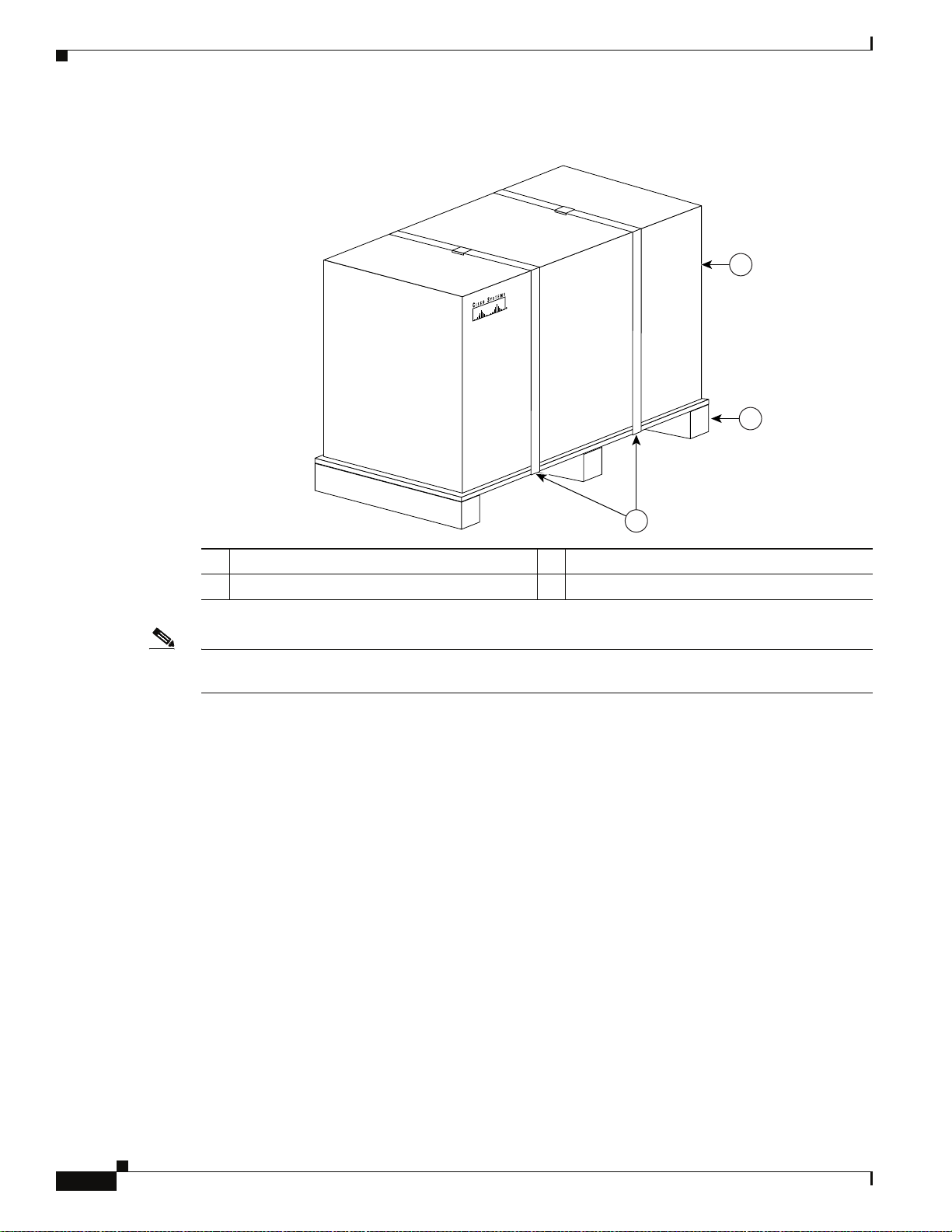
Chassis-Lifting Guidelines
Figure 3-2 Cisco ASR 1000 Series Router Packaged for Shipping
Chapter 3 Preparing Your Site for Installation
1
2
1 Outside carton 3 Packing straps
2 Pallet
Note We recommend that you have at least two people available to help with the installation and ensure safe
lifting.
Chassis-Lifting Guidelines
The fully configured system weighs approximately 75 pounds. The chassis is not intended to be moved
frequently. Before you install the system, ensure that your site is properly prepared so you can avoid
having to move the chassis later to accommodate power sources and network connections.
Two or more people are required to lift the chassis. Each time you lift the chassis or any heavy object,
follow these guidelines:
• Never attempt to lift the chassis by yourself. Because of the size and weight of the chassis, use at
least two people to safely lift and move it without causing injury or damaging the equipment.
• Ensure that your footing is solid, and balance the weight of the chassis between your feet.
132823
3
3-20
• Lift the chassis slowly; never move suddenly or twist your body as you lift.
• Keep your back straight and lift with your legs, not your back. If you must bend down to lift the
chassis, bend at the knees, not at the waist, to reduce the strain on your back muscles.
• Do not remove installed components from the chassis.
• Always disconnect all external cables before lifting or moving the chassis.
Cisco ASR 1000 Series Aggregation Services Routers Hardware Installation and Initial Configuration Guide
OL-13208-03
Page 95

Chapter 3 Preparing Your Site for Installation
Step 1 Each person should stand on either side of the chassis and place one hand under the air intake at the
bottom front of the chassis.
Step 2 With the other hand, grasp the top rear of the chassis under the air exhaust and carefully lift the chassis.
Tools and Equipment
The tools and equipment listed below are recommended as the minimum necessary to install the
Cisco
ASR 1000 Series Router. You may need additional tools and equipment to install associated
equipment and cables. You may also require test equipment to check electronic and optical signal levels,
power levels, and communications links.
• Phillips hand screwdriver
• A 3.5mm flat-blade screwdriver
• Tape measure (optional)
• Level (optional)
Tools and Equipment
• Power drill
Unpacking and Verifying Shipping Contents
When you receive your chassis, perform the following steps and use the shipping contents checklist from
the next section:
Step 1 Inspect the box for any shipping damage. (if there is damage contact your service representative).
Step 2 Unpack the Cisco ASR 1000 Series Router.
Step 3 Perform a visual inspection of the chassis.
Step 4 After you have unpacked the system verify that you have received all of the required components. Using
the packing list as a guide, take the following steps to check the contents of the Cisco
Router shipping container:
Step 5 Check the contents of the boxes containing accessory items. Verify that you have received all equipment
listed in your order.
Step 6 Check that all Cisco ASR 1000 Series RP1s, Cisco ASR1000-ESP10s, Cisco ASR1000-ESP5, Cisco
ASR 1000 Series SPA Interface (SIP), and power supplies you ordered are installed in the chassis.
Ensure that the configuration matches the packing list.
ASR 1000 Series
Checking the Shipping Container Contents
Use the components list to check the contents of the Cisco ASR 1000 Series Router shipping container.
Do not discard the shipping container. You need the container if you move or ship the Cisco ASR 1000
Series Router in the future.
Cisco ASR 1000 Series Aggregation Services Routers Hardware Installation and Initial Configuration Guide
OL-13208-03
3-21
Page 96

Chapter 3 Preparing Your Site for Installation
Checking the Shipping Container Contents
Table 3-10 Cisco ASR 1000 Series Router Shipping Container Contents List
Component Description Received
Chassis Cisco ASR 1000 Series Router configured with dual AC or dual DC
power supplies and a shared port adapter blank panel if a shared port
adapter has not been ordered.
Accessories Kit Front and rear chassis rack-mount brackets that you will attach to the
chassis with the respective screws
Three sets of screws, one set for:
• Front rack-mount brackets (use the black screws)
• Rear rack-mount brackets (use the package with the 5 screws)
• Cable-management brackets (use the 4 screw package)
Two cable-management brackets with ‘U’ feature design devices
attached; a different size for each chassis.
ESD, Wrist Strap (disposable) 1 disposable wrist strap
Documentation Regulatory Compliance and Safety Information for Cisco Aggregation
Services 1000 Series Chassis document
Optional Equipment Power cord if an AC power supply was shipped. There are none for the
DC power supply units.
Note Most Cisco documentation is online or on the Cisco Documentation DVD. Documentation that ships
with your Cisco ASR1000 Series router includes the Regulatory Compliance and Safety Information for
the Cisco
Aggregation Services Router 1000 Series document, and the Cisco Aggregation Services
Router 1000 Series Documentation Roadmap that contains documentation titles and the URLs to them
online. See also the “Related Documentation” section on page xviii.
3-22
Cisco ASR 1000 Series Aggregation Services Routers Hardware Installation and Initial Configuration Guide
OL-13208-03
Page 97

Chapter 3 Preparing Your Site for Installation
Cisco ASR 1000 Series Router Installation Checklist
Cisco ASR 1000 Series Router Installation Checklist
To assist you with your installation and to provide a historical record of what was done by whom,
photocopy the Cisco ASR 1000 Series Router Installation Checklist. Use this to indicate when each
procedure or verification is completed. When the checklist is completed, place it in your site log along
with the other records for your new router.
Table 3-11 Cisco ASR 1000 Series Router Installation Checklist
Tas k
Date chassis received
Chassis and all accessories unpacked
Types and numbers of interfaces verified
Safety recommendations and guidelines reviewed
Installation Checklist copied
Site log established and background information entered
Site power voltages verified
Site environmental specifications verified
Required passwords, IP addresses, device names, and so on, available
Required tools available
Network connection equipment available
Cable-management bracket installed (optional but recommended)
AC power cable(s) connected to AC source(s) and router
DC power cable(s) connected to DC source(s) and router
Network interface cables and devices connected
System power turned on
System boot complete (STATUS LED is on)
Shared port adapters are operational
Correct hardware configuration displayed after system banner appears
Verified
By Date
OL-13208-03
Cisco ASR 1000 Series Aggregation Services Routers Hardware Installation and Initial Configuration Guide
3-23
Page 98

Cisco ASR 1000 Series Router Installation Checklist
Chapter 3 Preparing Your Site for Installation
3-24
Cisco ASR 1000 Series Aggregation Services Routers Hardware Installation and Initial Configuration Guide
OL-13208-03
Page 99

CHAPTER
4
Cisco ASR 1006 Router Overview and Installation
This chapter describes the Cisco ASR 1006 Router and provides the procedures for installing the
Cisco
ASR 1006 Router on an equipment shelf or tabletop or in equipment racks. It also describes how
to connect interface and power cables.
This chapter contains the following sections:
• Cisco ASR 1006 Router Description, page 4-1
• General Rack Installation Guidelines, page 4-4
• Guidelines for an Equipment Shelf or Tabletop Installation, page 4-5
• Equipment Shelf or Tabletop Installation, page 4-6
• Rack-Mounting a Cisco ASR 1006 Router, page 4-8
• Attaching the Cable-Management Bracket, page 4-16
• Attaching a Chassis Ground Connection, page 4-17
• Connecting Power to Cisco ASR 1006 Router, page 4-21
• Connecting a Terminal to the Cisco ASR 1000 Series RP1 Console Port, page 4-27
• Connecting System Cables, page 4-29
Cisco ASR 1006 Router Description
The Cisco ASR 1006 Router supports full-width card modules. It is designed with a single midplane with
connectors on one interface midplane. The Cisco ASR 1006 Router supports:
• Three Cisco ASR 1000 Series SPA Interface Processor (SIP)
• Twelve SPA s l o t s
• Two Cisco ASR 1000 Series Embedded Services Processor (Cisco ASR1000-ESP10 or Cisco
ASR1000-ESP20)
• Two Cisco ASR 1000 Series Route Processor 1 (RP1)
• Dual (redundant) AC and DC power supplies
This section contains the following topics:
• Front View, page 4-2
• Rear View, page 4-2
OL-13208-03
Cisco ASR 1000 Series Aggregation Services Routers Hardware Installation and Initial Configuration Guide
4-1
Page 100

Cisco ASR 1006 Router Description
Front View
Chapter 4 Cisco ASR 1006 Router Overview and Installation
Figure 4-1 shows the Cisco ASR 1006 Router with modules and filler plates installed.
Figure 4-1 Cisco ASR 1006 Router —Front View
A
A
A
/
C/
C
L
L
/
/
A
A
1
A
/
C
L
/
A
1
A
/
C
L
/
A
1
A
/
C
L
/
A
1
A
/
C
L
/
A
1
A
/
C
L
/
A
1
01
01
2
2
2
2
2
2
HD
USB
BF
DISK
HD
USB
BF
DISK
A
C/
L
/
A
A
C/
L
/
A
A
C/
L
/
A
A
C/
L
/
A
A
/
C
L
/
A
CO
PWR
STAT
ASR1000-ESP10
PWR
STAT
ASR1000-ESP10
PWR
ACTV
STBY
STAT
ASR1000-RP1
ACTV
PWR
STBY
STAT
ASR1000-RP1
0
0
0
0
0
0
ACTV
STBY
ACTV
STBY
CRIT
MAJ
A
MIN
CRIT
MAJ
ACO
MIN
7
6
5
2
2
1
1
0
0
4
3
2
1
R1
R1
R0
R0
A
/
C/
C
L
L
/
/
A
A
SPA-4XOC3-POS
3
A
A
/
C/
C
L
L
/
/
A
A
SPA-4XOC3-POS
3
A
A
/
C/
C
L
L
/
/
A
A
SPA-4XOC3-POS
3
A
A
/
C/
C
L
L
/
/
A
A
SPA-4XOC3-POS
3
A
A
/
C/
C
L
L
/
/
A
A
SPA-4XOC3-POS
3
A
A
/
/
C
C
L
L
/
/
A
A
SPA-4XOC3-POS
3
ASR1000-SIP10
S
U
AT
T
S
S
U
AT
T
S
ASR1000-SIP10
S
U
AT
T
S
S
U
AT
T
S
ASR1000-SIP10
S
U
AT
T
S
S
U
AT
T
S
CARRIER
CARRIER
PWR STATUS
PWR STATUS
PWR STATUS
LINK
MGMT ETHERNET
BITS CON AUX
LINK
MGMT ETHERNET
BITS CON AUX
A
A
A
/
/
C
C
L
L
/
/
A
0
0
0
0
0
0
A
1
A
/
C
L
/
A
A
/
C
L
/
A
A
/
C
L
/
A
A
/
C
L
/
A
A
/
C
L
/
A
2
A
/
C
L
/
A
1
2
A
/
C
L
/
A
1
2
A
/
C
L
/
A
1
2
A
/
C
L
/
A
1
2
A
/
C
L
/
A
1
2
A
/
C/
C
S
L
/
A
A
C/
L
/
A
A
C/
L
/
A
A
C/
L
/
A
A
C/
L
/
A
A
/
C
L
/
A
U
L
/
AT
A
T
S
SPA-4XOC3-POS
3
A
/
C
S
U
L
/
AT
A
T
S
SPA-4XOC3-POS
3
A
/
C
S
U
AT
A/L
T
S
SPA-4XOC3-POS
3
A
/
C
S
U
L
/
AT
A
T
S
SPA-4XOC3-POS
3
A
/
C
S
U
L
/
AT
A
T
S
SPA-4XOC3-POS
3
A
/
C
S
U
L
/
AT
A
T
S
SPA-4XOC3-POS
3
1 Slot RP0 with ASR 1000 Series RP1 5 ASR 1000 Series SIP slot 0
2 Slot RP1 with ASR 1000 Series RP1 6 ASR 1000 Series SIP slot 1
3 Slot FP0 with ASR 1000 Series ESP 7 ASR 1000 Series SIP slot 2
4 Slot FP1 with ASR 1000 Series ESP
Cisco ASR 1006
2
1
0
F1F1
F0F0
R1
R0
280032
Rear View
Cisco ASR 1000 Series Aggregation Services Routers Hardware Installation and Initial Configuration Guide
4-2
Figure 4-2 shows the rear of the Cisco ASR 1006 Router with an AC power supplies installed.
OL-13208-03
 Loading...