

Page 1

CHA PT ER
2
Cisco ASR 1000 Series Routers Components
The Cisco ASR 1000 Series Routers contain the following components:
• Cisco ASR 1000 Series Route Processor 1, page 2-1
• Cisco ASR 1000 Series Embedded Services Processor, page 2-8
• Cisco ASR 1000 Series SPA Interface Processor, page 2-10
• Cisco ASR 1000 Series Router Power Supplies, page 2-14
Note Throughout this document, the term slot refers to a Cisco ASR 1000 Series Router chassis slot. The
Cisco ASR 1000 Series Route Processor 1, Cisco ASR 1000 Series Embedded Services Processor, and
Cisco ASR 1000 Series SPA Interface Processor, and power supplies plug into these slots. SPAs plug
into SIP bays.
Cisco ASR 1000 Series Route Processor 1
The Cisco ASR 1000 Series Route Processor 1 (RP1) is the central network clocking card and is
responsible for:
• Cisco ASR 1000 Series Routers field-replaceable unit (FRU) online insertion and removal (OIR).
• Selection of the active Cisco ASR 1000 Series Route Processor 1 and the Cisco ASR 1000 Series
Embedded Services Processor and notification of the Cisco ASR 1000 Series SPA Interface
Processor of these events.
• All the control processors communicating and performing packet processing on packets punted to it
by the Cisco ASR 1000 Series Embedded Services Processor (ESP).
Specific system tasks performed by the Cisco ASR 1000 Series Route Processor 1including the
following:
• Runs the router control plane, including network control packets, and connection setup
• User interfaces: 10/100/1000 Management Ethernet, CON/AUX, USB
• Active and standby Cisco ASR 1000 Series Route Processor 1 and Cisco ASR 1000 Series
Embedded Services Processor master and standby synchronization (Tasks include switchover from
failing master to standby.)
• Code storage, management, and upgrade
OL-13208-01
Cisco ASR 1000 Series Aggregation Services Routers Hardware Installation and Initial Configuration Guide
2-1
Page 2

Cisco ASR 1000 Series Route Processor 1
• Downloading operational code for SIPs and Cisco ASR 1000 Series Embedded Services Processor
over Ethernet out of band channel (EOBC), which is used for communication between the control
processors on the Cisco ASR 1000 Series Routers
• CLI, alarm, network management, logging, and statistics aggregation
• Chassis management
• Ethernet out-of-band management
• Punt path processing for packets not supported by the forward processor
Cisco ASR 1000 Series Route Processor 1 Features
The Cisco ASR 1000 Series Route Processor 1 (RP1) is the route processor that receives and transmits
all network packets through the active embedded services processor. The Cisco ASR 1000 Series RP1:
• Provides a configuration repository along with a hard disk drive (optionally a solid-state drive) for
logging system statistics, records, events, errors, and dumps (for both the Cisco ASR 1006 Router
and Cisco ASR 1004 Router).
• Provides the management interfaces of the platform including Dual Asynchronous
Receiver/Transmitter (DUART) that is used for the CON serial ports and Ethernet (ENET)
management ports, CLI, status indicators, BITS interface, reset switch, ACO switch, and USB ports
for secure keys.
• Provides chassis management (environmental, online insertion and removal)
Chapter 2 Cisco ASR 1000 Series Routers Components
• Provides non-volatile storage for the system used as the image and configuration repository along
with the logger for system statistics, records, events, errors, and dumps.
• Is responsible for the chassis management including activation and initialization of the other cards,
selection or switchover of active versus standby cards, image management and distribution, logging
facilities, distribution of user configuration information, and alarm control.
• Provides control signals and Ethernet out of band channel (EOBC) for the two Cisco ASR 1000
Series Embedded Services Processors and one other Cisco ASR 1000 Series Route Processor 1.
• Includes control signals for monitoring the health of power entry modules, shutting down the power
and driving alarm relays located on the power entry modules.
• Has high power (500mA) or low power (100mA) USB devices supported on both ports.
Note Cables coming off the front of the Cisco ASR 1000 Series Route Processor 1 utilize the chassis-level
cable-management brackets provided on the chassis rack-mount brackets.
The Cisco ASR 1000 Series RP1 module consists of a front panel label for indicator and control
functions and a separate label for the I/O connectors. The Cisco ASR 1000 Series RP1 model number
labeling is located on the left card module handle. The module also contains card handles to assist in
insertion or removal of the module.
2-2
Cisco ASR 1000 Series Aggregation Services Routers Hardware Installation and Initial Configuration Guide
OL-13208-01
Page 3
Chapter 2 Cisco ASR 1000 Series Routers Components
01
DISK
BF
USB
HD
MIN
ACO
MAJ
STBY
ACTV
STAT
ASR1000-RP1
PWR
CRIT
CARRIER
LINK
MGMT ETHERNET
BITS CON AUX
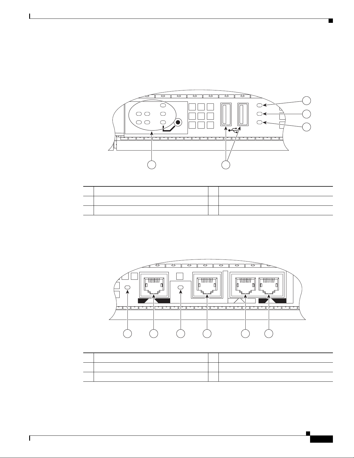
Figure 2-1 shows the Cisco ASR 1000 Series RP1 faceplate for the Cisco ASR 1006 Router and
ASR 1004 Router.
Figure 2-1 Cisco ASR Series 1000 RP1 Faceplate LEDs and Connectors
Cisco ASR 1000 Series Route Processor 1
1
2
3
280078
5
4
1 Internal hard drive LED 4 USB 0, USB 1 connector
2 External USB Flash LED 5 ASR1000 RP1 LEDs
3 Internal USB bootflash LED
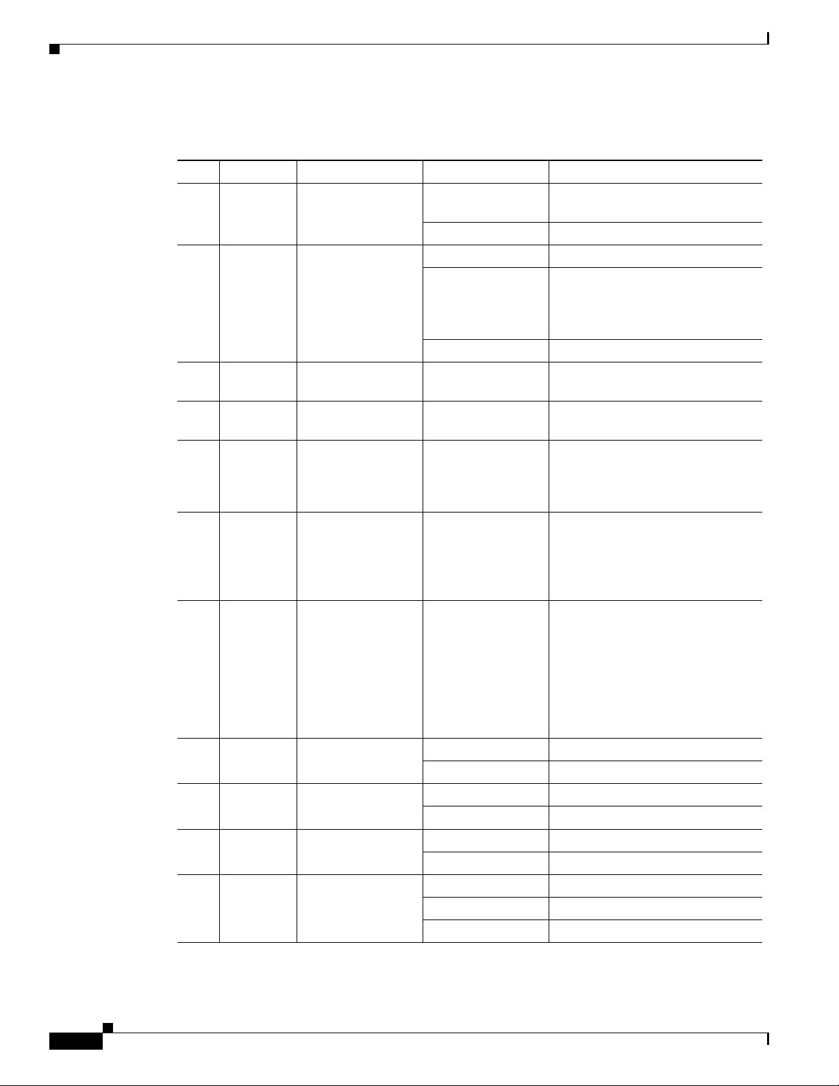
Figure 2-2 shows the Cisco ASR 1000 Series RP1 with faceplate connectors.
Figure 2-2 Cisco ASR Series 1000 RP1 Connectors
280079
OL-13208-01
6 45 3 2 1
1 AUX connector 4 LINK LED
2 CON connector 5 BITS connector
3 MGMT Ethernet connector 6 CARRIER LED
Cisco ASR 1000 Series Aggregation Services Routers Hardware Installation and Initial Configuration Guide
2-3
Page 4
Cisco ASR 1000 Series Route Processor 1
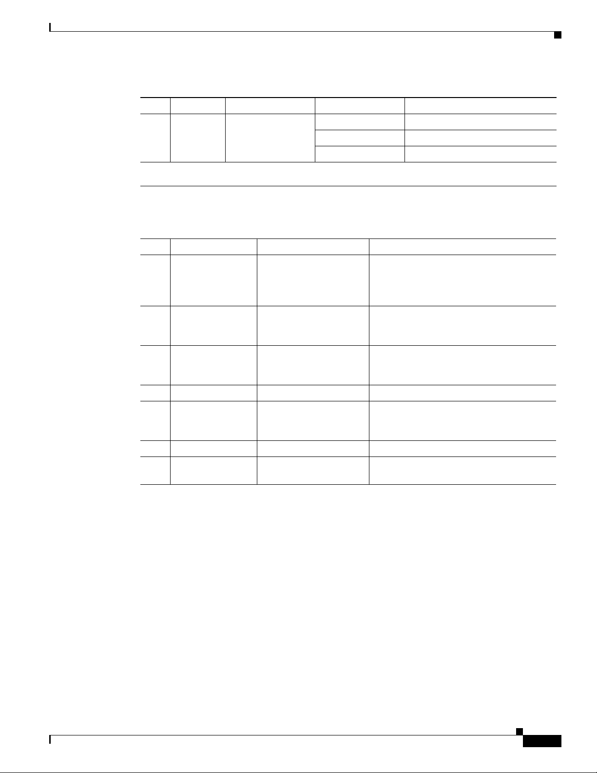
Table 2-1 lists the Cisco ASR 1000 Series RP1 LEDs and behaviors.
Table 2-1 Cisco ASR 1000 Series Route Processor 1 LEDs
No. LED Label LED Color —State Behavior Description
1 PWR Power Solid green All power requirements are within
2 STAT System status Solid green Cisco IOS has successfully booted.
3 ACTV Active Green Lit when this is the active Cisco
4 STBY Standby Yellow Lit when this is the standby
5 CRIT* Critical Solid Red Critical alarm indicator. For
6 MAJ* Major Solid Red Major alarm indicator. For
7 MIN* Minor Amber Minor alarm indicator. Ambient air
8 DISK HD Internal hard drive
9 DISK USB External USB Flash
10 DISK BF Internal USB
11 CARRIER LED Off Out of service or not configured.
LED
LED
bootflash LED
Chapter 2 Cisco ASR 1000 Series Routers Components
specification
Off Off, the router is in standby mode.
Yellow ROMMON is running or when the
Process Manager declares that a
critical ASR 1000 Series RP1
process is not running
Red System failure or powering up.
ASR 1000 Series RP1.
ASR1000 Series RP1.
example: Ambient air temperature
is above 60ºC and will begin
shutdown in 5 minutes.
example: Ambient air temperature
is beyond short term operating
range of 55ºC. System will shut
down above 60ºC.
temperature is beyond normal
operating range of 40ºC. For
example: if the RP software determines that an unknown card has
been installed or if the card has
failed, the card can power it off or
set a minor alarm.
Flashing Green Active indicator.
Off No activity.
Flashing Green Active indicator.
Off No activity.
Flashing Green Active indicator.
Off No activity.
Solid Green In frame and working properly.
Amber Fault of loop condition exists.
2-4
Cisco ASR 1000 Series Aggregation Services Routers Hardware Installation and Initial Configuration Guide
OL-13208-01
Page 5
Chapter 2 Cisco ASR 1000 Series Routers Components
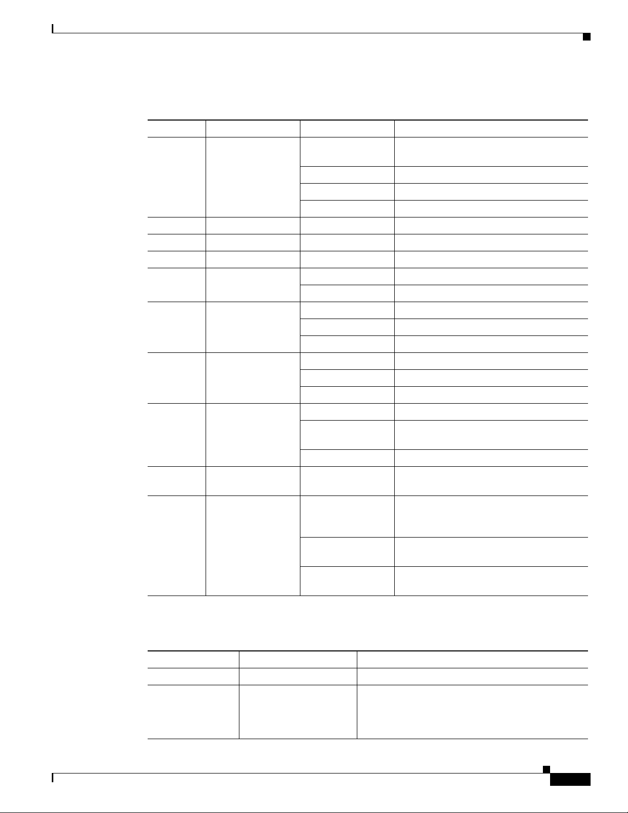
Table 2-1 Cisco ASR 1000 Series Route Processor 1 LEDs (continued)
No. LED Label LED Color —State Behavior Description
12 LINK 10/100/1000 RJ-45
Interface LED
* The type of alarm triggered is associated with the driver itself. For example, environmental alarms are tied to our
environmental code, SONET alarms are tied to the sonet code, ENET to Ethernet.
Table 2-2 lists the Cisco ASR 1000 Series RP1 connectors and description.
Table 2-2 Cisco ASR 1000 Series RP1 Connectors
No. Label Type Description
1 ACO Alarm cutoff switch. When you press this button, an interrupt is
2 0 USB connector 0 Side-by-side USB connector used with
3 1 USB connector 1 Side-by-side USB connector used with
4 BITS RJ45 connector Indicates BITS timing reference.
5 MGMT
ETHERNET
6 CON One RJ-45 for CON Console port used to connect to a terminal.
7 AUX One RJ-45 for AUX Auxiliary port used for remote management
Solid Green Link with no activity.
Flashing Green Link with activity.
Off No link.
One RJ-45 jack for
copper Ethernet
Management Port
Cisco ASR 1000 Series Route Processor 1
generated informing software that the
audible alarm relays will be disabled. This
interrupt generates to both processors.
memory sticks or smart cards for secure key
distribution
memory sticks or smart cards for secure key
distribution
The route processor has an ENET port with
a RJ-45 connector to attach a management
device or network for network management.
purposes.
OL-13208-01
The Cisco ASR 1000 Series RP1 meets the following requirements:
• Supports up to 4GB of ECC-protected memory with single-bit error correction and multi-bit error
detection
• Supports On-board Failure Logging (OBFL) with 2MB of memory
• Supports the Cisco ASR 1000 Series Router system architecture, midplane, and the Cisco ASR 1006
Router
• Enhanced Serdes Interconnect (ESI) at 11.5 G bps.
• Gigibit Ethernet switches for EOBC communication and boot-up of the Cisco ASR 1000 Series SPA
Interface (SIP) and Cisco ASR 1000 Series Embedded Services Processor.
• Runs Cisco IOS network control plane (routing protocol, connections setup)
• Cisco IOS punt packet forwarding
• Active/Standby Cisco ASR 1000 Series Route Processor 1 and Cisco ASR 1000 Series Embedded
Services Processor selection
Cisco ASR 1000 Series Aggregation Services Routers Hardware Installation and Initial Configuration Guide
2-5
Page 6

Cisco ASR 1000 Series Route Processor 1
• Code storage and download operational code to Cisco ASR 1000 Series Embedded Services
Processor and Cisco ASR 1000 Series SPA Interface (SIP)
• Bulk storage is 40G hard disk drive (SSD optional)
• I/O support: 2 Mb upgradeable BootRom, 1GB Embedded USB memory (EUSB)
• 512 MB embedded USB, 1GB on RP1 for Cisco ASR 1006 Router and ASR 1004 Router, and 8GB
on Cisco ASR 1002 Router
• Front panel support: Console, 10/100/1000 Management port, and two USB ports
The two serial ports can run up to 115.2kbps with hardware flow control. One port is used as the
CONSOLE port for secure configuration and status display. The default BAUD rate for the CONSOLE
port should be set at 9600 BAUD. The console port is an asynchronous serial port; any devices connected
to this port must be capable of asynchronous transmission.
The auxiliary port connects a modem or other DCE device (such as a CSU/DSU or other router) to allow
remote service and dial backup access to the system. Both the console and auxiliary ports are
asynchronous serial ports; any devices connected to these ports must be capable of asynchronous
transmission.'The AUX port is a diagnostics access port.
Chapter 2 Cisco ASR 1000 Series Routers Components
Cisco Embedded ASR1000-RP1 for Cisco ASR 1002 Router
The route processor for the Cisco ASR 1002 Router supports all the typical customer management
interfaces such as the Ethernet network management port and console and auxiliary serial ports of the
route processor for the Cisco ASR 1006 and ASR 1004 routers. It also has LED status indicators, an
RJ45 plug for a BITS timing reference and one USB ports which can be used with smart cards for secure
key distribution or for image or configuration file updates. The route processor is part of the 12V power
supply distribution and provides control for the power supplies.
The route processor for the Cisco ASR 1002 Router provides connection for one SPA bay and the
circuitry for the a built-in 4xGE SPA.
The Cisco embedded ASR1000-RP1 for the Cisco ASR 1002 Router meets the requirements of route
processor for the Cisco ASR 1006 and ASR 1004 routers in addition to these features:
• Supports up to 4GB of ECC protected field-replaceable memory with single-bit error correction and
multi-bit error detection.
• eUSB based bulk storage supports 8GB on the Cisco ASR 1006 Router and the Cisco ASR 1004
Router. On the Cisco ASR 1002 Router, the bulk storage and eUSB bootflash are a single 8GB eUSB
device (no hard disk or SSD).
• IO support: 2Mbyte upgradeable BootRom, minimum 512MB EUSB
• Front panel support: Console and Aux port, 10/100/1000 management port, one USB port, and
Status and Alarm LEDs.
• Supports Stratum-3 network clocking with T1/E1 BITS interface or SPAs as timing sources.
2-6
Cisco ASR 1000 Series Aggregation Services Routers Hardware Installation and Initial Configuration Guide
OL-13208-01
Page 7
Chapter 2 Cisco ASR 1000 Series Routers Components
Table 2-3 lists the Cisco embedded ASR1000-RP1 LEDs and behaviors.
Table 2-3 Cisco Embedded ASR1000-RP1 LEDs
LED Label LED Color —State Behavior Description
PWR Power Green All power requirements are within
STAT System status Green Cisco IOS has successfully booted.
MIN Minor Amber Minor alarm indicator.
MAJ Major Red Major alarm indicator.
CRIT Critical Red Critical alarm indicator.
BOOT EUSB0 FLASH
(BootDisk
CARRIER Off Out of service or not configured.
LINK 10/100 /1000 RJ-45
Interface LED
4 LEDs Built-in SPA SFP
port status
PWR SIP card power Green All SIP10 requirements are within specifi-
STAT SIP card status Green Only when the SPA drivers have started and
Cisco ASR 1000 Series Route Processor 1
specification
Yellow BootROM has successfully loaded.
Red System failure.
Flashing Green Active indicator.
Off No activity.
Green In frame and working properly.
Amber Fault or loop condition.
Green Link with no activity.
Flashing Green Link with activity.
Off No link.
Off Port is not enabled.
Amber Port enabled but there is a problem with the
Ethernet link.
Green Port enabled, valid Ethernet link
cation.
are running and all critical processes are
running
Yellow When ROMMON is running and during the
download and boot of the operating system
Red A fault is detected or the card is powering
up.
OL-13208-01
Table 2-4 lists the Cisco embedded ASR1000-RP1 connectors and description.
Table 2-4 Cisco Embedded ASR1000-RP1 Connectors
Label Type Description
BITS RJ45 connector Indicates BITS timing reference.
MGMT One RJ-45 jack for
copper Ethernet
Management Ethernet
The route processor has an ENET port with a RJ-45
connector to attach a management device or network
for network management.
Port
Cisco ASR 1000 Series Aggregation Services Routers Hardware Installation and Initial Configuration Guide
2-7
Page 8
Cisco ASR 1000 Series Embedded Services Processor
Table 2-4 Cisco Embedded ASR1000-RP1 Connectors (continued)
Label Type Description
CON One RJ-45 for CON Console port used to connect to a terminal.
AUX One RJ-45 for AUX Auxiliary port used for remote management
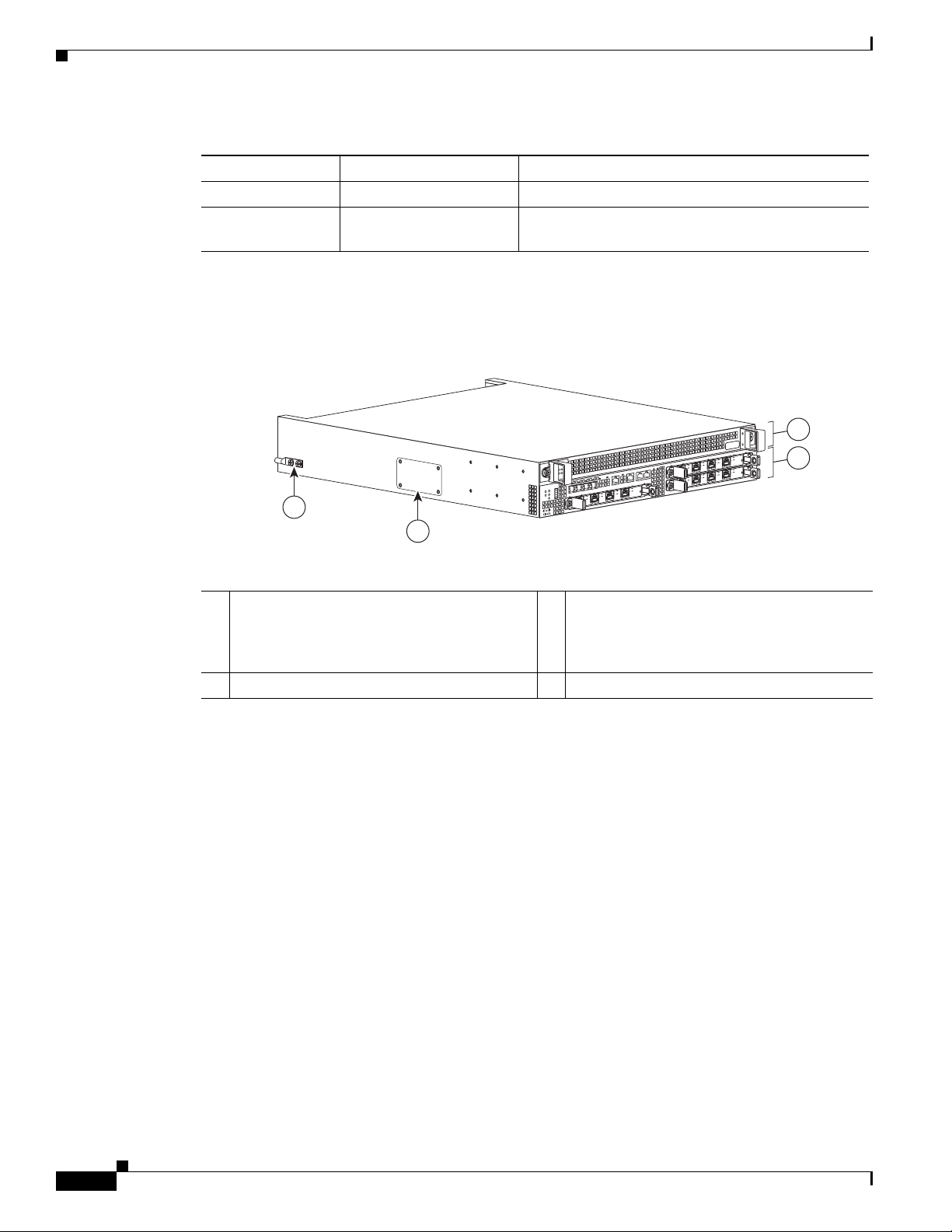
Figure 2-3 shows a fully-loaded Cisco ASR 1002 Router.
Figure 2-3 Cisco ASR 1002 Router Route Front View
4
Chapter 2 Cisco ASR 1000 Series Routers Components
purposes.
1
S
/A
U
C
T
A
T
/A
S
/L
C
T
S
R
W
P
N
O
C
X
U
A
MT
G
M
K
N
I
L
S
R
E
I
ARR
C
T
O
O
B
3
E
Q
2
QE
1
E
Q
0
QE
T
TA
S
002
1
R
AS
in
m
t
a
t
s
aj
m
r
w
p
A
/
C
it
r
c
/L
A
0
S
A
/
U
C
T
A
T
/A
L
S
/
C
A
/A
/L
C
A
-POS
SPA-4XOC3
/L
A
3
2
1
3
L
/
A
0
/A
C
L
/
A
0
S
2
/A
C
TU
TA
1
/A
L
/
S
C
A
A
/
L
/
C
OS
A
3-P
4XOC
-
A
P
S
/L
A
3
2
1
A
/A
/L
C
OS
A
3-P
4XOC
-
A
P
S
/A
L
/
C
A
ATMT
3
2
280283
1 FO slot 3 The eUSB panel door on the side of the Cisco
ASR 1002 Router must not be opened. If there
is a problem with eUSB flash card, the chassis
should be returned.
2 R0 slot 4 Grounding stud
The Cisco ASR 1000 Series Route Processor for the Cisco ASR 1002 Router deviates from the other
route processor in the following ways:
• No SATA hard drive supported. Bulk file storage is on a large fixed EUSB device (up to 8GB
supported).
• No support for redundant route processors.
• Network clock changes. No second BITS clock input supported.
• The connector and mechanical support for one half height SPA bay is included.
• The LED order is from top to bottom on the route processor is MIN, MAJ, CRIT.
Cisco ASR 1000 Series Embedded Services Processor
The Cisco ASR 1000 Series Embedded Services Processor (ESP) is based on the Cisco QuantumFlow
Processor for next-generation forwarding and queuing. provides the centralized embedded services
processor responsible for the bulk of the data plane processing tasks. All network traffic through the
Cisco ASR1000 Series system flows through the Cisco ASR 1000 Series Embedded Services Processor.
2-8
Cisco ASR 1000 Series Aggregation Services Routers Hardware Installation and Initial Configuration Guide
OL-13208-01
Page 9

Chapter 2 Cisco ASR 1000 Series Routers Components
The Cisco ASR 1000 Series Embedded Service Processors, Cisco ASR 1000-ESP5 and Cisco
ASR1000-ESP10 provide two centralized forwarding-engine options for the Cisco ASR 1000 Series
Aggregation Services Routers. The Cisco ASR 1000 Series ESPs:
• Are responsible for the data-plane processing tasks and all network traffic flows through them.
• Perform all baseline packet routing operations, including MAC classification, Layer 2 and Layer 3
forwarding, quality-of-service (QoS) classification, policing and shaping, security access control
lists (ACLs), VPNs, load balancing, and NetFlow.
• Are responsible for features such as firewalls, intrusion prevention, Network Based Application
Recognition (NBAR), Network Address Translation (NAT), and flexible pattern matching.
The 5-Gbps Cisco ASR 1000 Series ESP (ASR1000-ESP5) supports 5-Gbps bandwidth and is supported
only on the Cisco ASR1002 Router chassis. The 10-Gbps Cisco ASR 1000 Series ESP supports 10-Gbps
bandwidth, is supported on all Cisco ASR 1000 Series chassis.
The Cisco ASR 1000 Series Routers support the following ESPs:
• Cisco ASR 1000 Series ESP10—Supports forwarding performance with up to 8 Mpps with baseline
features and bandwidth of 10Gbps. The Cisco ESP10 is located in:
–
Cisco ASR 1006 Router physical slots 3 and 4 and are labeled F0 and F1.
Cisco ASR 1000 Series Embedded Services Processor
–
Cisco ASR 1004 Router physical slot 1 and is labeled F0.
–
Cisco ASR 1002 (which can use either the ESP10 or the ESP5; but Cisco ASR 1002 Router is
the only chassis that supports Cisco ASR1000-ESP5)
• Cisco ASR 1000 Series ESP5—Supports forwarding performance with up to 4 Mpps with baseline
features and bandwidth of 5Gbps. The Cisco ASR1000-ESP5 is in slot 1 and is labeled F0 in the
Cisco ASR 1002 Router.
The Cisco ASR 1000 Series Embedded Services Processor consists of three main elements:
• Embedded services processor for packet processing and queueing and scheduling
• Data plane interconnect
• Forwarding Engine Control Processor (FECP) (located on the Cisco ASR Series Embedded Services
Processor)
The forwarding processors for all initial Cisco ASR 1000 Series Embedded Services Processors are
based on a common highly-programmable network Cisco QuantumFlow Processor (packet processing).
The Cisco ASR 1000 Series Embedded Services Processor (ESP) consists of a front panel label for
indicator and control functions. The Cisco ASR 1000 Series Embedded Services Processor model
number labeling is located on the left card module handle. The module also contains card handles to
assist in insertion or removal of the module.
OL-13208-01
Cisco ASR 1000 Series Aggregation Services Routers Hardware Installation and Initial Configuration Guide
2-9
Page 10
Cisco ASR 1000 Series SPA Interface Processor
STBY
ACTV
STAT
ASR1000-ESP10
PWR
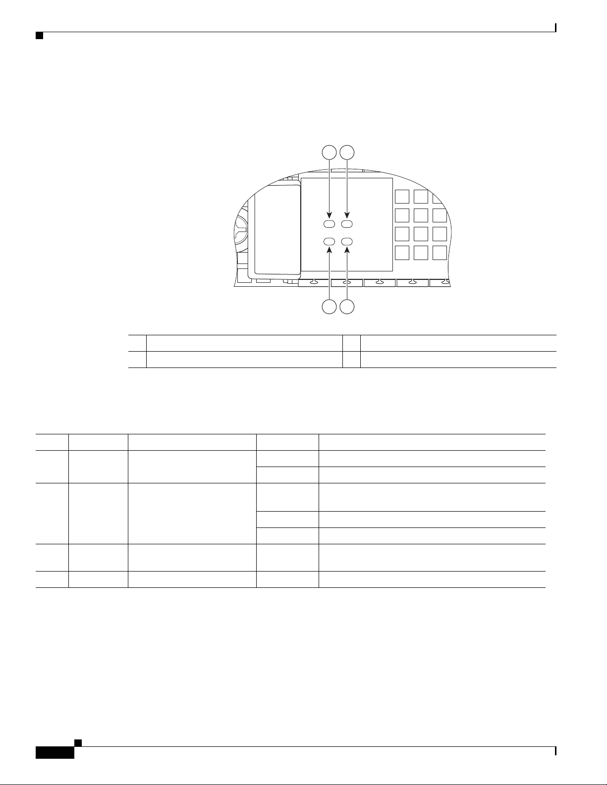
Figure 2-4 shows the Cisco ASR 1000 Series Embedded Services Processor (ESP10) LEDS on the front
panel.
Figure 2-4 Cisco ASR1000-ESP10 Faceplate LEDs
Chapter 2 Cisco ASR 1000 Series Routers Components
2
1
280080
3
4
1 Power LED 3 Status LED
2 Active LED 4 Standby LED
Table 2-5 lists the Cisco ASR1000-ESP5 or ASR1000-ESP10 LEDs and behaviors.
Table 2-5 Cisco ASR1000-ESP5 or ESP-10 Processor LEDs for the Cisco ASR 1002 Router
LED Label LED Color In the Power Up State -Behavior Description
1 PWR Power Solid green All power supplies are within operational limits.
Off Off, the router is in standby mode.
3 STAT STATUS Green Code has successfully downloaded and is
operational.
Yellow BOOT ROM has successfully loaded.
Red Not booted.
2 ACTV Active Green
4 STBY Standby None Will always be off.
The embedded services processor is green when
active.
Cisco ASR 1000 Series SPA Interface Processor
2-10
This section describes the SPA interface processor for the Cisco ASR 1006 Router, Cisco ASR 1004
Router and the Cisco ASR 1002 Router.
The Cisco ASR 1000 Series SPA Interface Processor for the Cisco ASR 1006 and Cisco ASR 1004
routers:
• Is a carrier card that inserts into a router slot like a line card.
Cisco ASR 1000 Series Aggregation Services Routers Hardware Installation and Initial Configuration Guide
OL-13208-01
Page 11
Chapter 2 Cisco ASR 1000 Series Routers Components
ASR1000-SIP10
PWR STATUS
• Contains one or more subslots which house one or more shared port adapters.
• Supports online insertion and removal (OIR) with SPAs inserted in the subslots. SPAs also support
OIR and can be inserted or removed independently from the SIP.
This section describes the Cisco ASR 1000 Series SPA Interface (SIP) components and subslot
identification.
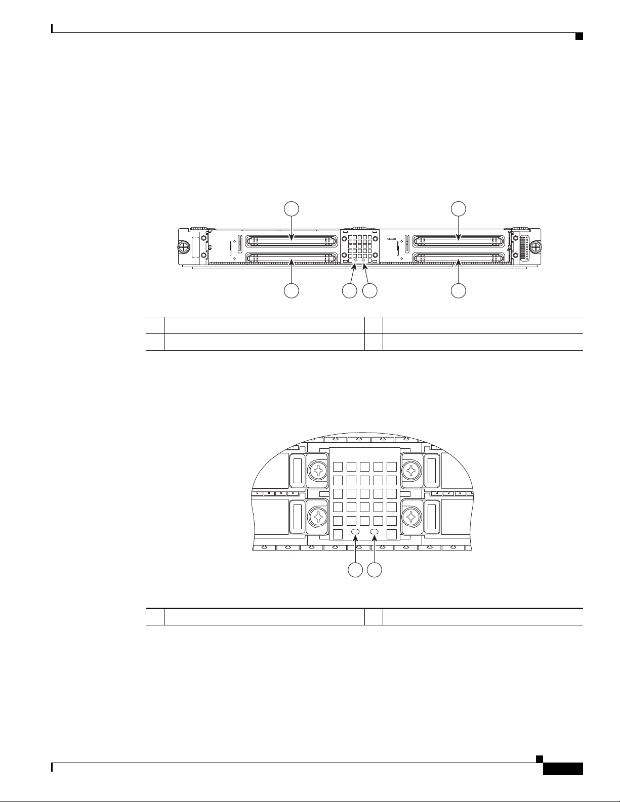
Figure 2-5 shows the Cisco ASR 1000 Series SPA Interface (SIP) module.
Figure 2-5 Cisco ASR 1000 Series SIP Faceplate
Cisco ASR 1000 Series SPA Interface Processor
1 2
0
ASR1000-SIP10G
2
6
ASR1000-SIP10
PWR STATUS
45 3
1 SPA subslot 0 3 SPA subslot 3
2 SPA subslot 1 4 SPA subslot 2
Figure 2-6 shows the LEDs on the Cisco ASR1000-SIP 10.
Figure 2-6 Cisco ASR1000-SIP10 SPA Interface Processor LEDs
1
3
231510
OL-13208-01
280081
12
1 PWR LED 2 Status LED
Cisco ASR 1000 Series Aggregation Services Routers Hardware Installation and Initial Configuration Guide
2-11
Page 12

Chapter 2 Cisco ASR 1000 Series Routers Components
Shared Port Adapters
Table 2-6 describes the Cisco ASR 1000 Series SIP10 LEDs on the front panel.
Table 2-6 Cisco ASR1000-SIP10 LEDs
No. LED Label LED Color—State Behavior Description
1 PWR Power status indicates the
status of the power supply
Off Cisco ASR 1000 Series SIP is powered
off
Green Cisco ASR 1000 Series SIP is powered
on
2 STATUS Indicates the current state of
the Cisco ASR 1000 Series
SPA Interface (SIP).
Red The Cisco ASR 1000 Series SPA
Interface Processor has encountered an
error
Yellow Lit when the Cisco ASR 1000 Series
SIP is loading
Green The SPA drivers have started and are
running and all critical processes are
running (as determined by the Cisco
ASR 1000 Series SPA Interface (SIP)
Process Manager).
The Cisco ASR 1002 Router supports a built-in 4xGE SPA and three half-height SPAs (one half-height
and one full height SPA). The Cisco embedded ASR1000-SIP10 on the Cisco ASR 1002 Router also
functions as the base board for the Cisco embedded ASR1000-RP1. The Cisco 1002 Router has one slot
for FP0 with three subslots for SPAs, subslots 1 - 3.
Shared Port Adapters
A shared port adapter is a modular type of port adapter that inserts into a subslot of a compatible SIP to
provide network connectivity and increased interface port density. The Cisco ASR 1000 Series SPA
Interface (SIP) provides an aggregation function for SPAs.
In the Cisco ASR 1006 Router, the Cisco ASR1000 Series SIP supports:
• 4 HH (¼ rate or full rate or combination)
• 2 FH (¼ rate or full rate or combination) SPAs with up to 32 ports per SPA
• 2 HH and 1 FH Combination that does not exceed 64 ports
Figure 2-7 shows the slot numbering for the shared port adapters on the Cisco ASR 1000 Series SPA
Interface for the Cisco ASR 1006 Router.
Figure 2-7 Cisco ASR 1000 Series SPA Interface Subslot Numbering for Cisco ASR 1006 Router
Front of SIP, horizontal chassis slots
2-12
SPA 0 SPA 1
SPA 2 SPA 3
231508
Cisco ASR 1000 Series Aggregation Services Routers Hardware Installation and Initial Configuration Guide
OL-13208-01
Page 13

Chapter 2 Cisco ASR 1000 Series Routers Components
In the Cisco ASR 1004 Router, the Cisco ASR1000 Series SIP supports:
• Four half height (¼ rate or full rate or combination)
• Two full height (¼ rate or full rate or combination) SPAs with up to 32 ports per SPA
The slot numbering for the SPAs in the Cisco ASR 1004 Router is the same as in the Cisco ASR 1006
Router.
In the Cisco ASR 1002 Router, the Cisco embedded ASR1000-SIP10 supports:
• Three removable half height SPAs on Bay 1, 2, and 3
• The fourth SPA which is a built-in 4xGE SPA on Bay 0 located on the Cisco ASR 1000 Series RP1
Note The shared port adapters on the Cisco embedded ASR1000-SIP10 support online insertion and
removal. However, the Cisco embedded ASR1000-SIP10 in the Cisco ASR 1002 Router is built
into the chassis and is not a field-replaceable unit and does not support online insertion and
removal.
Figure 2-8 shows the slot numbering for the shared port adapters on the Cisco ASR 1000 Series SPA
Interface for the Cisco ASR 1002 Router.
Shared Port Adapters
Figure 2-8 Cisco Embedded ASR1000-SIP10 Interface Subslot Numbering
ASR 1002
pwr
stat
min
maj
crit
PWR
STAT
ASR1000-ESP10
ACTV
STBY
QE0 QE1 BOOT
STAT
0
1
LINK PWR STATQE2 QE3
C
A
R
R
I
E
R
A
A
/
/
C
C
/L
/L
A
A
1
2
/A
/A
C
C
/L
A
S
U
L
T
/
A
A
T
S
SPA-4XOC3-POS
3
A
/
C
L
/
A
0
A
C/
L
/
A
0
2
3
A
/
C
L
/
A
1
2
A
/
C
L
A/
1
2
A
/
C
C/A
L
A/
A
/
C
L
/
A
US
L
/
AT
A
T
S
SPA-4XOC3-POS
3
A
/
C
US
L
AT
A/
T
S
SPA-4XOC3-POS
3
280369
4
1 Cisco embedded ASR1000-RP1 subslot 0 3 SPA subslot 1
2 SPA subslot 2 4 SPA subslot 3
The Cisco embedded ASR1000-SIP10 supports one built-in 4xGE SPA and three half height SPAs in any
one of the following configurations:
• Built-in 4xGE SPA in bay 0 and three half height SPAs in bay 1, 2, 3.
• Built-in 4xGE SPA in bay 0, one half height SPA in bay 2, and one full height SPA in bay 1.
The Cisco ASR 1000 Series SPA interface processor houses SPA bay 2 and SPA bay 3. SPA bay 0 and
SPA bay 1 are physically located on Cisco embedded ASR1000-RP1. A portion of the Cisco embedded
ASR1000-RP1 is reserved to provide connectivity between SPA bay 1 and the Cisco embedded
ASR1000-SIP10.
OL-13208-01
For information about specifying SIP subslot location for a SPA and specifying slot location for a SIP,
see the Cisco Aggregation Services Router 1000 Series SIP and SPA Installation Guide.
Cisco ASR 1000 Series Aggregation Services Routers Hardware Installation and Initial Configuration Guide
2-13
Page 14

Chapter 2 Cisco ASR 1000 Series Routers Components
Cisco ASR 1000 Series Router Power Supplies
Cisco ASR 1000 Series Router Power Supplies
All Cisco ASR 1000 Series Router configurations support AC and DC power supply options. The
modular chassis configurations support the installation of two power supplies for redundancy. When an
external power supply fails or is removed, the other power supply provides power requirements for the
chassis.
You are required to always have two power supplies installed in the chassis to insure sufficient cooling
for the box. The system fans are inside the power supply unit and must spin for cooling. No Cisco
ASR 1000 Series Router will operate for more than two to three minutes without two power supplies
installed. Since all the system fans can be powered by one power supply, it is not required for the second
power supply unit to be powered on, but it must be installed. Cisco IOS software specifically looks for
two power supplies in the chassis and will automatically initiate a shutdown if only one power supply is
detected.
This section contains the following topics:
• Power Supply Requirements for All Cisco ASR 1000 Series Routers, page 2-14
• Power Supplies for Cisco ASR 1006 Router, page 2-16
• Power Supplies for Cisco ASR 1004 Router, page 2-21
• Power Supplies for Cisco ASR 1002 Router, page 2-26
Power Supply Requirements for All Cisco ASR 1000 Series Routers
This section contains power supply specifications for the Cisco ASR 1006, ASR 1004, and ASR 1002
routers. The following topics are covered:
• DC power supply input ratings and circuit breaker specifications
–
Maximum and minimum Amps for the branch circuit breakers
–
Maximum and minimum size of the AWG wire required for each circuit breaker.
• AC and DC power supply types
• AC and DC power supply ratings
2-14
Cisco ASR 1000 Series Aggregation Services Routers Hardware Installation and Initial Configuration Guide
OL-13208-01
Page 15

Chapter 2 Cisco ASR 1000 Series Routers Components
Cisco ASR 1000 Series Router Power Supplies
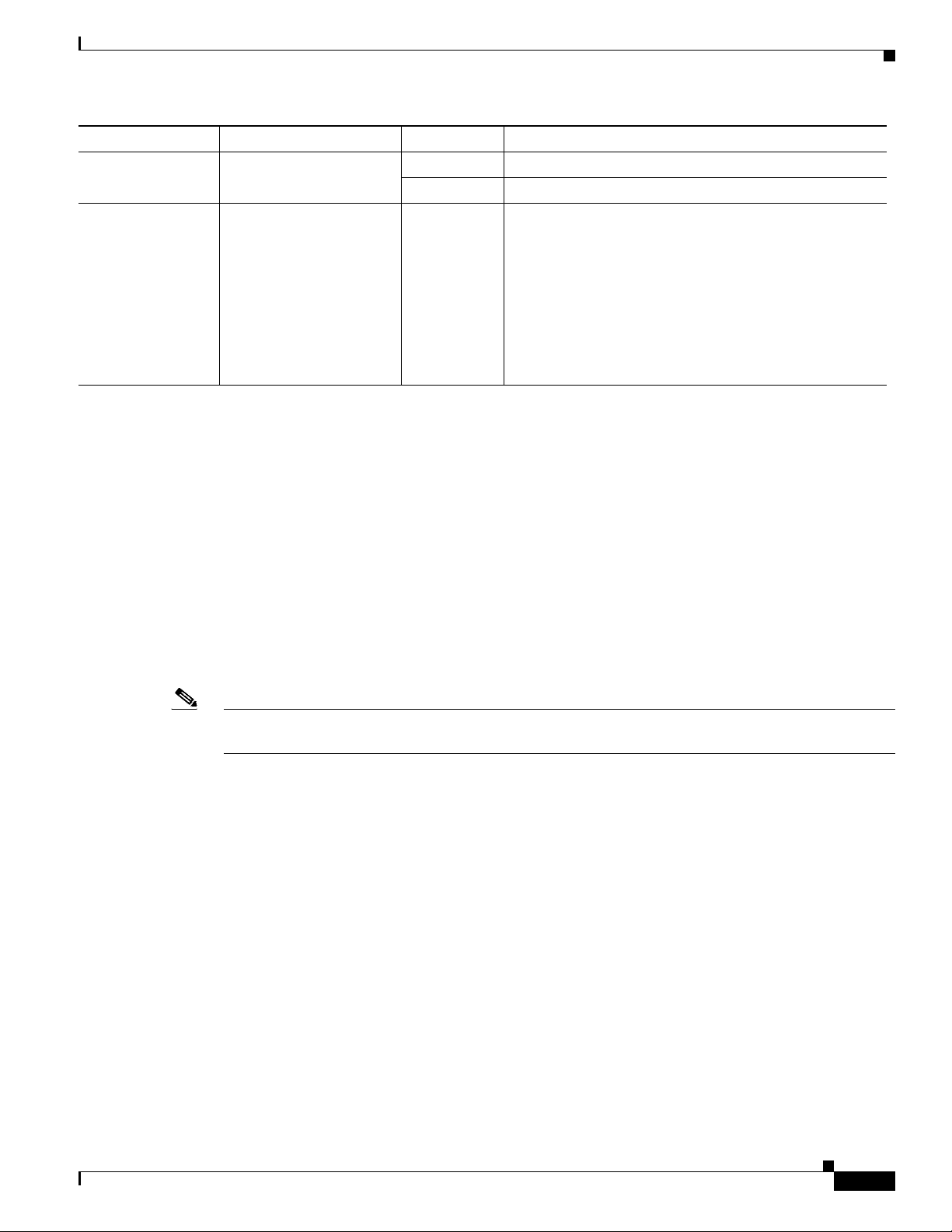
DC Power System Input Requirements for Cisco ASR 1000 Series Routers
The DC power supply for the Cisco ASR 1006, ASR 1004, and ASR 1002 routers operate at
specifications. shows the common input ranges and circuit breaker requirements.
Table 2-7 Cisco ASR 1000 Series Router DC Power Supply System Input Requirements
Cisco ASR 1000
Series Router DC
Power Supply System Input Rating (Amps) Circuit Breaker Amps AWG # Wire
Minimum Maximum Minimum Maximum
Cisco ASR 1006 40 Always 50 Always AWG #6 wire
Cisco ASR 1004 24 30 40 10 8
Cisco ASR 1002 16 20 30 12 10
For example, the Cisco ASR 1002 Router DC power supply, with 16 Amp input rating must use an AWG #12 gauge wire for a 20Amp circuit breaker and
an AWG #10 gauge wire for a 30Amp circuit breaker.
Note All Cisco ASR 1000 Series Router AC power supplies require a 20 AMP circuit breaker.
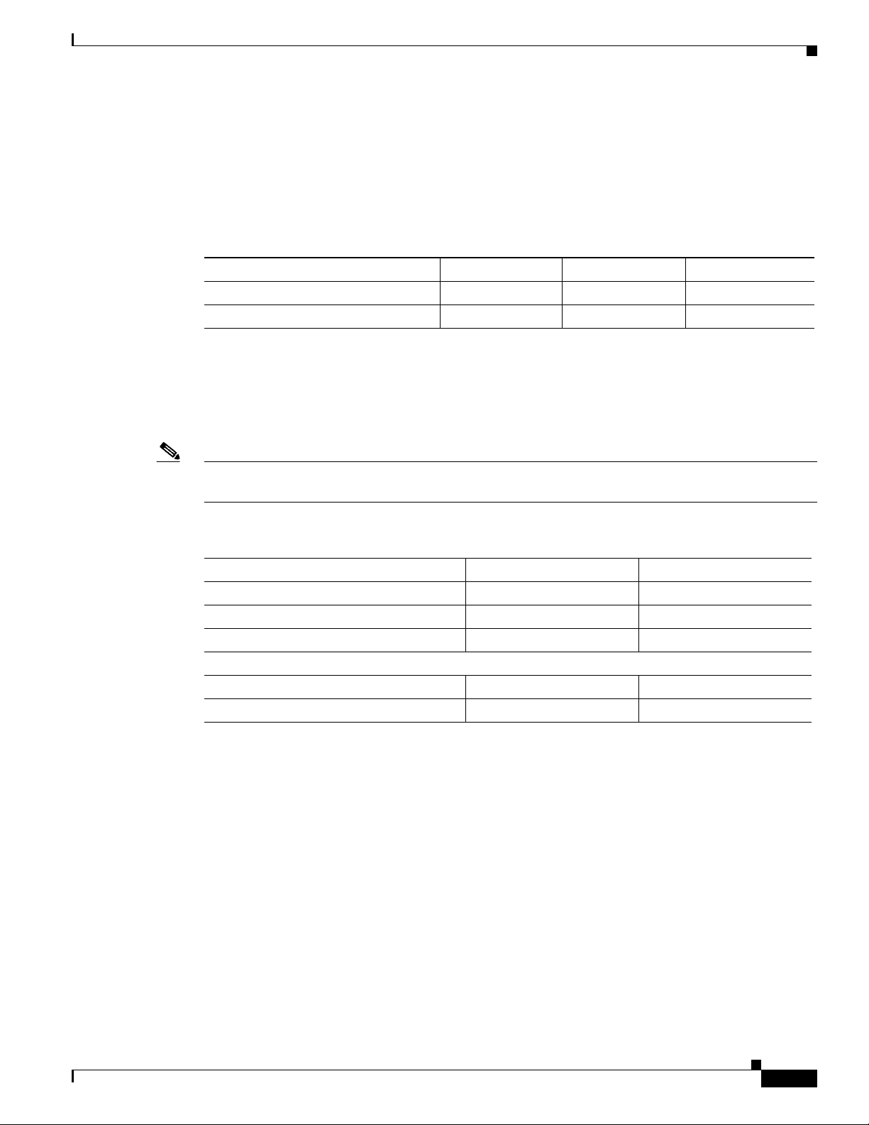
AC and DC Power Supply Types
The AC and DC power supplies for the Cisco ASR 1000 Series Routers support different types of power
supply switches. Table 2-8 defines which power supplies the Cisco ASR 1000 Series routers support (a
Standby or an On/Off switch).
Table 2-8 Cisco ASR 1000 Series Routers AC and DC Power Supply Switches
Switch Type
Supported
On/Off circuit I/O ASR 1006 DC
Standby switch A broken
Symbol Cisco ASR 1000 Series Router Power Supply
ASR 1004 DC
ASR 1002 AC
ASR 1006 AC
circle with
a vertical
line
ASR 1004 AC
ASR 1002 DC
through the
top of it
AC and DC System Power Ratings
Table 2-9 lists AC and DC power supply system rating requirements for all Cisco ASR 1000 Series
Routers.
Cisco ASR 1000 Series Aggregation Services Routers Hardware Installation and Initial Configuration Guide
OL-13208-01
2-15
Page 16

Chapter 2 Cisco ASR 1000 Series Routers Components
Cisco ASR 1000 Series Router Power Supplies
Table 2-9 AC and DC Power Supply System Rating Specifications for the Cisco ASR 1000 Series Routers
Description Specification
Power supply declared ratings AC = 100-240 VAC
DC = –48/ –60 VDC
Nominal line frequency rating 50/60 Hz
Power Supplies for Cisco ASR 1006 Router
The Cisco ASR 1006 Router can support up to 1200W output (AC and DC input). The 1200W power
supply module consists of either an AC or DC input and 1200 watt output closed frame power supply
with two DC voltage outputs: 12V and 3.3V.
Each power supply module contains three internal fan modules and provides the forced air cooling for
the chassis. These power supply modules contain a monitor circuit to determine the status of fan speed
and operation along with LED status indicating fan errors.
The system temperature operation is 0 to 40C normal and –5C to +55C.
• AC System—AC power input is an IEC 320-type power inlet, 20A service connector. The AC input
side contains a front panel with provisions for mounting screw, built in handle to extract the power
supply, three status LEDs, and fans for power supply and system cooling.
• DC System—Two-position terminal block-style connector, with labeled connections for - (–48/60 V
input) and + (–48/60 V Return). The DC input side contains a front panel with provisions for
mounting screw, built in handle to extract the power supply, three status LEDs, and fans for power
supply and system cooling.
See Appendix A, “Cisco ASR 1000 Series Routers Specifications.” for detailed power supply
specifications.
Warning
This product relies on the building’s installation for short-circuit (overcurrent) protection. Ensure that
the protective device is rated not greater than: AC power supplies for the Cisco Aggregation Services
Routers: 120 VAC, 20A U.S. maximum. DC power supplies for the Cisco ASR 1006 Router: 50A U.S.
maximum; Cisco ASR 1004 Router: 40A U.S. maximum: Cisco ASR 1002 Router: 30A U.S. maximum.
Statement 1005
AC Power Supply LEDs and Connector for Cisco ASR 1006
This section provides information about the AC power supplies on the rear of the Cisco ASR 1006
Router. The power supply module contains three fans mounted in the power supply module. A total of
six fans are used to cool the ASR 1006 system and power supply. The airflow direction is front to back.
Power supply modules with internal fan modules install into the rear of the chassis. These modules
contain integral handles to ease installation and removal (no insertion or extraction levers are provided).
A single blind mate connector located on the inlet side of these modules mates with a connector mounted
on back side of the midplane.
Guide pins located at the rear of these modules help center locate the modules and reduce stress to the
midplane and module mounted connectors. Four captive screws (tool operated latches) are provided on
the modules face plate (chassis rear) to secure these modules into the chassis.
2-16
Cisco ASR 1000 Series Aggregation Services Routers Hardware Installation and Initial Configuration Guide
OL-13208-01
Page 17

Chapter 2 Cisco ASR 1000 Series Routers Components
Figure 2-9 shows the AC power supplies at the rear of the Cisco ASR 1006 Router.The Cisco ASR 1006
Router supports up to two power supplies. The power supply LEDs and connectors on the rear of the
chassis are described in Table 2-1 0.
Figure 2-9 Cisco ASR 1006 Router AC Power Supply
Cisco ASR 1000 Series Router Power Supplies
6 7
100-240V~ 16-7A
5
50-60HZ
This unit might have more than
one power supply connection.
All connections must be removed
to de-energize the unit.
4
8
OUTPUT INPUT INPUT
FAIL OK OK
ALARMS
60V
1A MAX
280029
2 13
1 AC power supply fan 5 AC power supply handle
2 DB-25 alarm connector 6 AC power inlet
3 Tie-wrap tab 7 AC power supply Standby switch
4 AC power supply captive screw 8 AC power supply LEDs
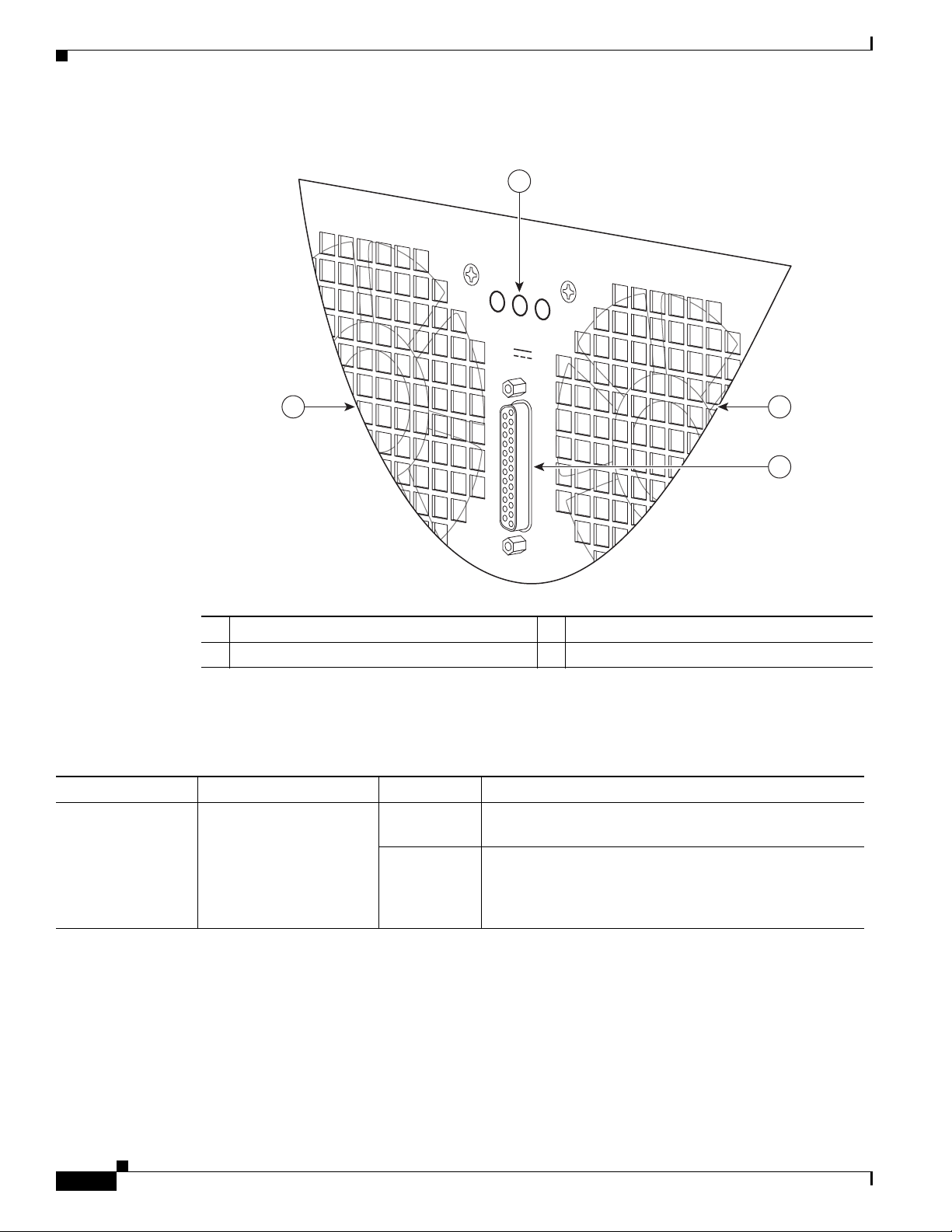
Figure 2-10 shows the AC power supplies LEDs and DB-25 alarm connector.
OL-13208-01
Cisco ASR 1000 Series Aggregation Services Routers Hardware Installation and Initial Configuration Guide
2-17
Page 18
Cisco ASR 1000 Series Router Power Supplies
1A MAX.
OUTPUT INPUT FAN
FAIL O K O K
ALARMS
60V
Figure 2-10 Cisco ASR 1006 Router AC Power Supply LEDs and DB-25 Alarm Connector
Chapter 2 Cisco ASR 1000 Series Routers Components
1
280028
24
3
1 AC power supply LEDs 3 DB-25 alarm connector
2 AC power supply fan 4 AC power supply fan
Table 2-10 describes the AC power supply LEDs on the Cisco ASR 1006 Router.
Table 2-10 Cisco ASR 1006 Router AC Power Supply LEDs and Connector
LED Label LED Color Description
INPUT OK Power supply activity Green LED illuminates green to signal that the AC power supply
input voltage is greater than 85V.
None If LED is not illuminated, then the AC input voltage is
less than 70V or the power supply is turned off. For an AC
input voltage between 70V and 85V, the INPUT OK LED
can be either on, off, or flashing
2-18
Cisco ASR 1000 Series Aggregation Services Routers Hardware Installation and Initial Configuration Guide
OL-13208-01
Page 19
Chapter 2 Cisco ASR 1000 Series Routers Components
Cisco ASR 1000 Series Router Power Supplies
LED Label LED Color Description
FAN OK Bi-color LED indicates
fan status
Green LED illuminates green when all fans are operational.
Red The LED illuminates red when a fan failure is detected.
OUTPUT FAIL Power supply activity Red LED is red and turned off to signal that the AC output
voltages are within the normal operating range; output
voltage between the minimum and maximum limits will
not create an output fail alarm, and output voltages below
the minimum or above the maximum will create an output
fail alarm.
When you turn the power supply on, the red LED is
illuminated for two to three seconds for testing LED
operation before going off.
DC Power Supply LEDs and Connectors for Cisco ASR 1006
This section provides information about the DC power supplies on the rear of the Cisco ASR 1006
Router. The maximum branch circuit for the DC power supply module is 60A and the minimum is 50A.
The DC power supply operates within specification from –48 VDC to –60 VDC continuously. The Cisco
ASR 1006 Router has two of the same type power supplies in power supply slot 0 and power supply
slot 1. The power supply slot numbers are on the left side of the chassis and the power supplies are
located on the floor of the chassis.
The DC input connector is a terminal block style that supports a AWG #6 wire. The terminal block is
compliant to all safety agencies and electrical requirements of the supply. Use the tie wraps to dress the
input cable wires. There are three tie wrap tabs on the power supply.
The terminal block accepts two double-hole lugs, one for –48V input and another for –48V RTN. A
plastic cover fits over the terminal block to prevent accidental contact. See Figure 5-18.
Note The studs on the terminal block are similar to the safety ground device on the side of the Cisco ASR 1006
Router. For information on the safety ground lug on the side of the chassis.
The unit requires a power switch circuit breaker to serve as the main disconnect for the DC input to the
power supply. The circuit breaker meets international safety requirements and supports 80 VDC and has
a current rating of 50 A. The power supply unit is secured into the system chassis with four captive
screws mounted on the faceplate.
Figure 2-11 shows the DC power supplies at the rear of the Cisco ASR 1006 Router. The Cisco ASR
1006 Router supports up to two power supplies. The power supply LEDs and connectors on the rear of
the chassis are described in the Tabl e 2-1 1.
OL-13208-01
Cisco ASR 1000 Series Aggregation Services Routers Hardware Installation and Initial Configuration Guide
2-19
Page 20

Cisco ASR 1000 Series Router Power Supplies
Figure 2-11 Cisco ASR 1006 Router DC Power Supply
Chapter 2 Cisco ASR 1000 Series Routers Components
9 10
-48/-60V 40A
8
7
This unit might have more than one power supply connection. All connections must be removed to de-energize the unit.
1 Fans 6 DC Power supply earth ground lugs
2 DB-25 alarm connector 7 DC Power supply captive screws
3 Tie-wrap tabs 8 DC Power supply handle
4 DC power supply terminal and plastic cover 9 DC power supply On (|) /Off (O) switch
5 Earth grounding symbol 10 DC power supply LEDs
Table 2-11 describes the LEDs on the Cisco ASR 1006 Router DC power supply.
Table 2-11 Cisco ASR 1006 Router DC Power Supply LEDs
OFF
55
OUTPUT INPUT INPUT
FAIL O K OK
ALARMS
60V
1A MAX
280023
2 145 36
LED Label LED Color Description
INPUT OK A bi-color LED
indicates
presence of
input voltage
Green LED illuminates green to signal that the DC power supply input
voltage is greater than–43.5VDC at turn-on and remains green down
to –39VDC.
Amber The LED illuminates amber when the input voltage (falls below
–39VDC) and indicates that there is still a voltage present (voltage on
the terminal block). The LED remains amber and is active to around
20V +/-5V. The LED is not illuminated if the input is below –15V.
FAN OK A bi-color LED
indicates power
supply fan status
OUTPUT FAIL Power supply
activity
Green The LED illuminates s green when all fans are operational.
Red The LED illuminates red when a fan failure is detected.
Red When the LED is off, it signals that the DC output voltage are within
the normal operating range. Output voltage between the minimum and
maximum limits will not create an output fail alarm, and output
voltages below the minimum or above the maximum will create an
Output Fail alarm.
When you turn the power supply on, the red LED illuminates for two
to three seconds to test LED operation before going off.
2-20
Cisco ASR 1000 Series Aggregation Services Routers Hardware Installation and Initial Configuration Guide
OL-13208-01
Page 21

Chapter 2 Cisco ASR 1000 Series Routers Components
AC/DC Power System Output for Cisco ASR 1006
The power supply output tolerance is defined in Ta ble 2-1 2 under all combinations of line variation.
Total system consumption per power supply should not exceed 1200 W.
Table 2-12 Cisco ASR 1006 Router Power System Output Voltage and Current
Output Voltage +12 VDC +3.3 V
Minimum 11.80 VDC 3.20 VDC
Nominal 12.00 VDC 3.30 VDC
Maximum 12.20 VDC 3.40 VDC
Output Current
Minimum 2.80 A 0.10 A
Maximum 101.7 A 3.125 A
Power Supplies for Cisco ASR 1004 Router
Cisco ASR 1000 Series Router Power Supplies
Warning
The Cisco ASR 1004 Router can support up to 735 W output (AC and DC input). The 735W power
supply module consists of either an AC or DC input with two DC voltage outputs: 12V and 3.3V.
Each power supply module contains three internal fan modules and provides the forced air cooling for
the chassis. These power supply modules contain a monitor circuit to determine the status of fan speed
and operation along with LED status indicating fan errors.
The system temperature operation is 0 to 40C and –5C to +55C.
• AC System—AC power input is an IEC 320-type power inlet, 15A service connector. The AC input
side contains a front panel with provisions for mounting screw, built in handle to remove the power
supply, three status LEDs, and fans for power supply and system cooling.
• DC System—Three-position terminal block-style connector, with labeled connections for -
(–48/60 V input) and + (–48/60 V Return) and GND (earth ground symbol). The DC input side
contains a front panel with provisions for mounting screw, built in handle to extract the power
supply, three status LEDs, and fans for power supply and system cooling.
See Appendix A, “Cisco ASR 1000 Series Routers Specifications.” for detailed power supply
specifications.
This product relies on the building’s installation for short-circuit (overcurrent) protection. Ensure that
the protective device is rated not greater than: AC power supplies for the Cisco Aggregation Services
Routers: 120 VAC, 20A U.S. maximum. DC power supplies for the Cisco ASR 1006 Router: 50A U.S.
maximum; Cisco ASR 1004 Router: 40A U.S. maximum: Cisco ASR 1002 Router: 30A U.S. maximum.
Statement 1005
Cisco ASR 1004 AC Power Supply
This section provides information about the AC power supplies on the rear of the Cisco ASR 1004
Router. The power supply module contains three fans mounted in the power supply module. A total of
six fans are used to cool the ASR 1004 system and power supply. The airflow direction is front to back.
Cisco ASR 1000 Series Aggregation Services Routers Hardware Installation and Initial Configuration Guide
OL-13208-01
2-21
Page 22

Cisco ASR 1000 Series Router Power Supplies
Power supply modules with internal fan modules install into the rear of the chassis. These modules
contain handles to ease installation and removal. The AC power supply has a front panel mounted switch
that powers on and off the power supply. This switch will not disconnect the AC line, but will act only
as a standby switch to the power supply. The front panel includes a mechanical guard to prevent the
standby switch from being tripped due to accidental contact.
Guide pins located at the rear of these modules help center locate the modules and reduce stress to the
midplane and module mounted connectors. Four captive screws (tool operated latches) are provided on
the modules face plate (chassis rear) to secure these modules into the chassis.
Cisco ASR 1004 AC Power Supply LEDs and Connector
Figure 2-12 shows the AC power supplies at the rear of the Cisco ASR 1004 Router.The Cisco ASR 1004
Router supports up to two power supplies. The power supply LEDs and connectors on the rear of the
chassis are described in Table 2-1 3.
Figure 2-12 Cisco ASR 1004 Router AC Power Supply
1 2
Chapter 2 Cisco ASR 1000 Series Routers Components
OUTPUTINPUT
FAN
OK OK
FAIL
100V-240V~ 12A-5A
50-60Hz
100V-240V~ 12A-5A
50-60Hz
6
5
1 AC power supply Standby switch (standby
4 AC power supply fan
ALARMS
60V
1A MAX
ALARMS
60V
1A MAX
OUTPUTINPUT
FAIL
OK OK
34
FAN
symbol is a broken circle with a vertical line
through the top of it)
2 AC power supply LEDs 5 AC power inlet
3 DB-25 alarm connector 6 AC power supply handle
280184
2-22
Cisco ASR 1000 Series Aggregation Services Routers Hardware Installation and Initial Configuration Guide
OL-13208-01
Page 23

Chapter 2 Cisco ASR 1000 Series Routers Components
1A MAX.
OUTPUT INPUT FAN
FAIL O K O K
ALARMS
60V
Figure 2-13 shows the AC power supplies LEDs and DB connector.
Figure 2-13 Cisco ASR 1004 Router AC Power Supply LEDs and DB -25 Alarm Connector
Cisco ASR 1000 Series Router Power Supplies
1
280028
24
3
1 AC power supply LEDs 3 DB-25 alarm connector
2 Power supply fan 4 AC power supply fan
Table 2-13 describes the AC power supply LEDs on the Cisco ASR 1004 Router.
Table 2-13 Cisco ASR 1004 Router AC Power Supply LEDs and Connector
LED Label LED Color Description
INPUT OK Power supply activity Green LED illuminates green to signal that the AC power supply
input voltage is greater than 85V.
None If LED is not illuminated, then the AC input voltage is
less than 70V or the power supply is turned off. For an AC
input voltage between 70V and 85V, the INPUT OK LED
can be either on, off, or flashing
OL-13208-01
Cisco ASR 1000 Series Aggregation Services Routers Hardware Installation and Initial Configuration Guide
2-23
Page 24

Chapter 2 Cisco ASR 1000 Series Routers Components
Cisco ASR 1000 Series Router Power Supplies
LED Label LED Color Description
FAN OK Bi-color LED indicates
fan status
Green LED illuminates green when all fans are operational.
Red The LED illuminates red when a fan failure is detected.
OUTPUT FAIL Power supply activity Red LED is red and turned off to signal that the AC output
voltages are within the normal operating range; output
voltage between the minimum and maximum limits will
not create an output fail alarm, and output voltages below
the minimum or above the maximum will create an output
fail alarm.
When you turn the power supply on, the red LED is
illuminated for two to three seconds for testing LED
operation before going off.
Cisco ASR Router 1004 DC Power Supply
This section provides information about the DC power supplies on the rear of the Cisco ASR 1004
Router. For the maximum branch circuit for the DC power supply module, see Tabl e 2-7.
The DC power supply operates within specification from –48 VDC to –60 VDC continuously. The Cisco
ASR 1004 Router has two of the same type power supplies in power supply slot 0 and power supply
slot 1. The power supply slot numbers are on the left side of the chassis and the power supplies are
located on the floor of the chassis.
The DC power supply input connector is a terminal block style that will allow crimp type lugs accepting
up to AWG #8 wire. The terminal block is compliant to all safety agencies and electrical requirements
of the supply. The terminal block accepts two-hole lugs (#10 stud) for all connections with center to
center spacing of 0.625 inches. A plastic cover goes over the terminal block to prevent accidental
contact. The connection order shall be negative (–), positive (+), and GND terminals.
The unit requires a power switch circuit breaker to serve as the main disconnect for the DC input to the
power supply (Table 2-7 see for current rating requirements.) The power supply unit is secured into the
system chassis with four captive screws mounted on the faceplate.
Cisco ASR 1004 Router DC Power Supply LEDs and Connector
Figure 2-14 shows the DC power supplies at the rear of the Cisco ASR 1004 Router. The Cisco
ASR 1004 Router supports up to two power supplies. The power supply LEDs and connectors on the rear
of the chassis are described in the Table 2-1 4.
2-24
Cisco ASR 1000 Series Aggregation Services Routers Hardware Installation and Initial Configuration Guide
OL-13208-01
Page 25

Chapter 2 Cisco ASR 1000 Series Routers Components
Figure 2-14 Cisco ASR 1004 Router DC Power Supply
Cisco ASR 1000 Series Router Power Supplies
1
67
60V
1A MAX
60V
1A MAX
OUTPUTINPUT
FAIL
OUTPUTINPUT
FAIL
2
OK OK
OK OK
345
FAN
FAN
1 DC power supply terminal and plastic cover 5 Earth grounding symbol
2 DC power supply LEDs 6 DC power supply On (|) /Off (O) switch
3 DB-25 alarm connector
7 DC power supply handle
Power supply ground lugs (+ and –)
4 DC power supply fan
280185
Table 2-14 describes the LEDs on the Cisco ASR 1004 Router DC power supply.
Table 2-14 Cisco ASR 1004 Router DC Power Supply LEDs
LED Label LED Color Description
INPUT OK A bi-color LED
indicates
presence of
input voltage
Green LED illuminates green to signal that the DC power supply input
voltage is greater than–43.5VDC at turn-on and remains green down
to –39VDC.
Amber The LED illuminates amber when the input voltage (falls below
–39VDC) and indicates that there is still a voltage present (voltage on
the terminal block). The LED remains amber and is active to around
20V +/-5V. The LED is not illuminated if the input is below –15V.
OL-13208-01
Cisco ASR 1000 Series Aggregation Services Routers Hardware Installation and Initial Configuration Guide
2-25
Page 26

Cisco ASR 1000 Series Router Power Supplies
LED Label LED Color Description
FAN OK A bi-color LED
indicates power
supply fan status
OUTPUT FAIL Power supply
activity
Green The LED illuminates s green when all fans are operational.
Red The LED illuminates red when a fan failure is detected.
Red When the LED is off, it signals that the DC output voltage are within
the normal operating range. Output voltage between the minimum and
maximum limits will not create an output fail alarm, and output
voltages below the minimum or above the maximum will create an
Output Fail alarm.
When you turn the power supply on, the red LED illuminates for two
to three seconds to test LED operation before going off.
DC Power System Input for Cisco ASR 1004
The DC power supply operates within specification from –40.5VDC to –72VDC continuously once the
the power supply DC input turn on threshold of –43.5V has been reached. Table 2-20 shows the common
input ranges for reference only.
Chapter 2 Cisco ASR 1000 Series Routers Components
Table 2-15 Cisco ASR 1004 Router DC Power System Input
Voltage Range (VDC) Minimum Nominal Maximum
Domestic –40.5 –48 –56
International –55 –60 –72
AC/DC Power System Output for Cisco ASR 1004
The power supply output tolerance is defined in Ta bl e 2-1 6 under all combinations of line variation.
Total system consumption per power supply should not exceed 735 W.
Table 2-16 Cisco ASR 1004 Router Power System Output Voltage and Current
Output Voltage +12 VDC +3.3 V
Minimum 11.80 VDC 3.20 VDC
Nominal 12.00 VDC 3.30 VDC
Maximum 12.20 VDC 3.40 VDC
Output Current
Minimum 2.80 A 0.10 A
Maximum 61.44A 3.125 A
Power Supplies for Cisco ASR 1002 Router
The Cisco ASR 1002 Router supports an AC or DC power supply:
• Cisco ASR 1002 Router AC Power Supply, page 2-27—The AC power supply operates between
85VAC and 264VAC. AC power input is an IEC 320-type power inlet, 15A service connector. The
AC input side contains a front panel with provisions for mounting screw, two built-in handles to
extract the power supply, three status LEDs, and fans for power supply and system cooling.
Cisco ASR 1000 Series Aggregation Services Routers Hardware Installation and Initial Configuration Guide
2-26
OL-13208-01
Page 27

Chapter 2 Cisco ASR 1000 Series Routers Components
• Cisco ASR 1002 Router DC Power Supply, page 2-29—The DC power supply operates between
–40.5VDC and –72VDC. Three-position euro-style terminal block, with labeled connections for –
(–48/60 V input) and + (–48/60 V Return) and the GND symbol for grounding. The DC input side
contains a front panel with provisions for mounting screw, built in handles to remove the power
supply, three status LEDs, and fans for power supply and system cooling.
Cisco ASR 1002 Router Power Supply Fans
Cisco ASR 1002 Router system level cooling is provided by two 12 VDC type fans in each power supply
module. The fans in each module provide system cooling back-up in the event of a single fan failure. In
addition, the fans in each of the power supplies can be powered from a single supply when only one unit
is operational. The airflow direction is front to back.
Cisco ASR 1000 Series Router Power Supplies
Warning
This product relies on the building’s installation for short-circuit (overcurrent) protection. Ensure that
the protective device is rated not greater than: AC power supplies for the Cisco Aggregation Services
Routers: 120 VAC, 20A U.S. maximum. DC power supplies for the Cisco ASR 1006 Router: 50A U.S.
maximum; Cisco ASR 1004 Router: 40A U.S. maximum: Cisco ASR 1002 Router: 30A U.S. maximum.
Statement 1005
Cisco ASR 1002 Router AC Power Supply
This section provides information about the AC power supplies on the rear of the Cisco ASR 1002
Router.
The Cisco ASR 1002 Router system level cooling is provided by two 12 VDC type fans in each of the
two power supply modules. The fans in each module are intended to provide system cooling back-up in
the event of a single fan failure. In addition, the fans in each of the power supplies can be powered from
a single supply when only one unit is operational. The airflow direction is front to back. A single
blind-mate connector located on the inlet side of these modules mates with a connector mounted on back
side of the midplane.
Guide pins located at the rear of these modules help center locate the modules and reduce stress to the
midplane and module mounted connectors. Two captive screws (tool operated latches) are provided on
the modules face plate (chassis rear) to secure these modules into the chassis.
Cisco ASR 1002 AC Power Supply LEDs and Connector
Figure 2-15 shows the AC power supplies at the rear of the Cisco ASR 1002 Router. The Cisco
ASR 1002 Router supports up to two power supplies. The power supply LEDs and connectors on the rear
of the chassis are described in Table 2-1 0.
OL-13208-01
Cisco ASR 1000 Series Aggregation Services Routers Hardware Installation and Initial Configuration Guide
2-27
Page 28

Cisco ASR 1000 Series Router Power Supplies
Figure 2-15 Cisco ASR 1002 Router AC Power Supply
Chapter 2 Cisco ASR 1000 Series Routers Components
2
0
41 5 63
OUTPUT INPUT
FAN OUTPUT INPUT
OK OK
FAIL
This unit might have more than
one power supply connection.
All connections must be removed
to de-energize the unit.
8 7
1 AC power supply ESD socket 5 AC power supply fan
2 AC power supply slot number 0 6 AC power supply captive installation screw
3 AC power supply On (I) /Off (O) switch 7 AC power supply slot number 1
4 AC power supply LEDs 8 AC power supply inlet
Table 2-17 describes the AC power supply LEDs on the Cisco ASR 1002 Router.
Table 2-17 Cisco ASR 1002 Router AC Power Supply LEDs
OK OK
FAIL
This unit might have more than
one power supply connection.
All connections must be removed
to de-energize the unit.
FAN
1
280288
LED Label LED Color Description
INPUT OK Power supply activity Green LED illuminates green to signal that the AC power supply
input voltage is greater than 85V.
None If LED is not illuminated, then the AC input voltage is
less than 70V or the power supply is turned off. For an AC
input voltage between 70V and 85V, the INPUT OK LED
can be either on, off, or flashing
FAN OK Bi-color LED indicates
fan status
Green LED illuminates green when all fans are operational.
Red The LED illuminates red when a fan failure is detected.
OUTPUT FAIL Power supply activity Red LED is red and turned off to signal that the AC output
voltages are within the normal operating range; output
voltage between the minimum and maximum limits will
not create an output fail alarm, and output voltages below
the minimum or above the maximum will create an output
fail alarm.
2-28
Cisco ASR 1000 Series Aggregation Services Routers Hardware Installation and Initial Configuration Guide
OL-13208-01
Page 29

Chapter 2 Cisco ASR 1000 Series Routers Components
AC Power System Output Voltage Alarm Range for Cisco ASR 1002
The AC power supply output voltage alarm occurs when the output voltage is below the low end of the
minimum or above the high end of the maximum limits shown inTab le 2- 18.
Table 2-18 Cisco ASR 1002 Router AC Power Supply Output Voltage Alarm Range
Minimum Maximum
12 V 10.0 to 11.2V 12.8 to 13.8 V
3.3 V 2.6 to 3.0V None
Cisco ASR 1002 Router DC Power Supply
This section provides information about the DC power supplies on the rear of the Cisco ASR 1002
Router. The recommended branch circuit breaker for the Cisco ASR 1002 Router DC power supply is
30Amp. Use an AWG #10 maximum wire gauge on the 30Amp circuit. The maximum branch circuit for
the DC power supply module must not exceed 30Amp.
The Cisco ASR 1002 Router has two of the same type power supplies in power supply slot 0 and power
supply slot 1. The power supply slot numbers are on the left side of the chassis and the power supplies
are located on the floor of the chassis. The power supply switch is a Standby switch and is not considered
a disconnect.
The DC input connector is a euro-style terminal block. The largest size gauge of wire that the front panel
euro-terminal block can accept is AWG #10 wire. The terminal block is compliant to all safety agencies
and electrical requirements of the power supply. Use the tie wraps to dress the input cable wires; there
are two tie wrap tabs on the DC power supply.
The DC power supply unit is secured into the system chassis with two captive screws mounted on the
faceplate.
Cisco ASR 1000 Series Router Power Supplies
Cisco ASR 1002 Router DC Power Supply LEDs and Connector
Figure 2-16 shows the DC power supplies at the rear of the Cisco ASR 1002 Router. The Cisco
ASR 1002 Router supports up to two power supplies. The power supply LEDs and connectors on the rear
of the chassis are described in the Tabl e 2-1 9.
OL-13208-01
Cisco ASR 1000 Series Aggregation Services Routers Hardware Installation and Initial Configuration Guide
2-29
Page 30

Cisco ASR 1000 Series Router Power Supplies
Figure 2-16 Cisco ASR 1002 Router DC Power Supply
Chapter 2 Cisco ASR 1000 Series Routers Components
2
1
0
4 5 63
OUTPUT INPUT
OK OK
FAIL
This unit might have more than
one power supply connection.
All connections must be removed
to de-energize the unit.
-48V/-60V 16A
FAN
OUTPUT INPUT
OK OK
FAIL
This unit might have more than
one power supply connection.
All connections must be removed
to de-energize the unit.
-48V/-60V 16A
FAN
9 810
DC power supply ESD socket
1
DC power supply slot 0 label
2
DC power supply switch Standby/On (I)
3
DC power supply captive installation screw
6
DC power supply slot 1 label
7
Negative ground lead
8
(standby symbol is a broken circle with a
vertical line through the top of it)
DC power supply LEDs
4
Fan
5
Positive ground lead
9
Earth ground lead
10
Table 2-19 describes the LEDs on the Cisco ASR 1002 Router DC power supply.
1
280289
7
Table 2-19 Cisco ASR 1002 Router DC Power Supply LEDs
LED Label LED Color Description
INPUT OK A bi-color LED
indicates
presence of
input voltage
Green LED illuminates green to signal that the DC power supply input
voltage is greater than–43.5VDC at turn-on and remains green down
to –39VDC.
Amber The LED illuminates amber when the input voltage (falls below
–39VDC) and indicates that there is still a voltage present (voltage on
the terminal block). The LED remains amber and is active to around
20V +/-5V. The LED is not illuminated if the input is below –15V.
FAN OK A bi-color LED
indicates power
supply fan status
OUTPUT FAIL Power supply
activity
Green The LED illuminates s green when all fans are operational.
Red The LED illuminates red when a fan failure is detected.
Red When the LED is off, it signals that the DC output voltage are within
the normal operating range. Output voltage between the minimum and
maximum limits will not create an output fail alarm, and output
voltages below the minimum or above the maximum will create an
Output Fail alarm.
When you turn the power supply on, the red LED illuminates for two
to three seconds to test LED operation before going off.
2-30
Cisco ASR 1000 Series Aggregation Services Routers Hardware Installation and Initial Configuration Guide
OL-13208-01
Page 31
Chapter 2 Cisco ASR 1000 Series Routers Components
DC Power System Input for Cisco ASR 1002
The DC power supply operates within specification from –40.5VDC to –72VDC continuously once the
the power supply DC input turn on threshold of –43.5V has been reached. Table 2-20 shows the common
input ranges for reference only. The DC power input connector is a euro-style terminal block with three
wires, one positive, one negative, and one grounding wire.
Table 2-20 Cisco ASR 1002 Router DC Power System Input
Voltage Range (VDC) Minimum Nominal Maximum
Domestic –40.5 –48 –56
International –55 –60 –72
DC Power System Output for Cisco ASR 1002
The DC power supply output tolerance is defined in Tab le 2 -21 under all combinations of DC input line
variation. Total system power consumption should not exceed 470 watts or output rating of each power
supply.
Cisco ASR 1000 Series Router Power Supplies
Note Two power supplies are used for redundant operation. System total power consumption shall never
exceed rating of one power supply to maintain redundancy.
Table 2-21 Cisco ASR 1002 Router DC Power System Output Voltage and Current
Output Voltage +12 VDC +3.3 V
Minimum –11.80 VDC –3.20 VDC
Nominal –12.00 VDC –3.30 VDC
Maximum –12.20 VDC –3.40 VDC
Output Current
Minimum –2.0 A –0.10 A
Maximum –39 A –3.125 A
OL-13208-01
Cisco ASR 1000 Series Aggregation Services Routers Hardware Installation and Initial Configuration Guide
2-31
Page 32

Cisco ASR 1000 Series Router Power Supplies
Chapter 2 Cisco ASR 1000 Series Routers Components
2-32
Cisco ASR 1000 Series Aggregation Services Routers Hardware Installation and Initial Configuration Guide
OL-13208-01
 Loading...