

Page 1

Cisco ASA Series Firewall ASDM
Configuration Guide
Software Version 7.1
For the ASA 5505, ASA 5510, ASA 5520, ASA 5540, ASA 5550, ASA 5512-X,
ASA 5515-X, ASA 5525-X, ASA 5545-X, ASA 5555-X, ASA 5580, ASA 5585-X,
and the ASA Services Module
Released: December 3, 2012
Updated: March 31, 2014
Cisco Systems, Inc.
www.cisco.com
Cisco has more than 200 offices worldwide.
Addresses, phone numbers, and fax numbers
are listed on the Cisco website at
www.cisco.com/go/offices.
Text Part Number: N/A, Online only
Page 2

THE SPECIFICATIONS AND INFORMATION REGARDING THE PRODUCTS IN THIS MANUAL ARE SUBJECT TO CHANGE WITHOUT NOTICE. ALL
STATEMENTS, INFORMATION, AND RECOMMENDATIONS IN THIS MANUAL ARE BELIEVED TO BE ACCURATE BUT ARE PRESENTED WITHOUT
WARRANTY OF ANY KIND, EXPRESS OR IMPLIED. USERS MUST TAKE FULL RESPONSIBILITY FOR THEIR APPLICATION OF ANY PRODUCTS.
THE SOFTWARE LICENSE AND LIMITED WARRANTY FOR THE ACCOMPANYING PRODUCT ARE SET FORTH IN THE INFORMATION PACKET THAT
SHIPPED WITH THE PRODUCT AND ARE INCORPORATED HEREIN BY THIS REFERENCE. IF YOU ARE UNABLE TO LOCATE THE SOFTWARE LICENSE
OR LIMITED WARRANTY, CONTACT YOUR CISCO REPRESENTATIVE FOR A COPY.
The Cisco implementation of TCP header compression is an adaptation of a program developed by the University of California, Berkeley (UCB) as part of UCB’s public
domain version of the UNIX operating system. All rights reserved. Copyright © 1981, Regents of the University of California.
NOTWITHSTANDING ANY OTHER WARRANTY HEREIN, ALL DOCUMENT FILES AND SOFTWARE OF THESE SUPPLIERS ARE PROVIDED “AS IS” WITH
ALL FAULTS. CISCO AND THE ABOVE-NAMED SUPPLIERS DISCLAIM ALL WARRANTIES, EXPRESSED OR IMPLIED, INCLUDING, WITHOUT
LIMITATION, THOSE OF MERCHANTABILITY, FITNESS FOR A PARTICULAR PURPOSE AND NONINFRINGEMENT OR ARISING FROM A COURSE OF
DEALING, USAGE, OR TRADE PRACTICE.
IN NO EVENT SHALL CISCO OR ITS SUPPLIERS BE LIABLE FOR ANY INDIRECT, SPECIAL, CONSEQUENTIAL, OR INCIDENTAL DAMAGES, INCLUDING,
WITHOUT LIMITATION, LOST PROFITS OR LOSS OR DAMAGE TO DATA ARISING OUT OF THE USE OR INABILITY TO USE THIS MANUAL, EVEN IF CISCO
OR ITS SUPPLIERS HAVE BEEN ADVISED OF THE POSSIBILITY OF SUCH DAMAGES.
Cisco and the Cisco logo are trademarks or registered trademarks of Cisco and/or its affiliates in the U.S. and other countries. To view a list of Cisco trademarks, go to this
URL: www.cisco.com/go/trademarks. Third-party trademarks mentioned are the property of their respective owners. The use of the word partner does not imply a partnership
relationship between Cisco and any other company. (1110R)
Any Internet Protocol (IP) addresses and phone numbers used in this document are not intended to be actual addresses and phone numbers. Any examples, command display
output, network topology diagrams, and other figures included in the document are shown for illustrative purposes only. Any use of actual IP addresses or phone numbers in
illustrative content is unintentional and coincidental.
Cisco ASA Series Firewall ASDM Configuration Guide
Copyright © 2012-2014 Cisco Systems, Inc. All rights reserved.
Page 3

About This Guide 21
Document Objectives 21
Related Documentation 21
Conventions 22
Obtaining Documentation and Submitting a Service Request 22
PART
1 Configuring Service Policies
CONTENTS
CHAPTER
1 Configuring a Service Policy 1-1
Information About Service Policies 1-1
Supported Features 1-1
Feature Directionality 1-2
Feature Matching Within a Service Policy 1-3
Order in Which Multiple Feature Actions are Applied 1-4
Incompatibility of Certain Feature Actions 1-5
Feature Matching for Multiple Service Policies 1-5
Licensing Requirements for Service Policies 1-5
Guidelines and Limitations 1-6
Default Settings 1-7
Default Configuration 1-7
Default Traffic Classes 1-8
Task Flows for Configuring Service Policies 1-8
Task Flow for Configuring a Service Policy Rule 1-8
Adding a Service Policy Rule for Through Traffic 1-8
Adding a Service Policy Rule for Management Traffic 1-13
Configuring a Service Policy Rule for Management Traffic 1-13
CHAPTER
Managing the Order of Service Policy Rules 1-15
Feature History for Service Policies 1-17
2 Configuring Special Actions for Application Inspections (Inspection Policy Map) 2-1
Information About Inspection Policy Maps 2-1
Guidelines and Limitations 2-2
Default Inspection Policy Maps 2-2
Cisco ASA Series Firewall ASDM Configuration Guide
1
Page 4

Contents
Defining Actions in an Inspection Policy Map 2-3
Identifying Traffic in an Inspection Class Map 2-3
Where to Go Next 2-4
Feature History for Inspection Policy Maps 2-4
PART
2 Configuring Network Address Translation
CHAPTER
3 Information About NAT (ASA 8.3 and Later) 3-1
Why Use NAT? 3-1
NAT Terminology 3-2
NAT Types 3-3
NAT Types Overview 3-3
Static NAT 3-3
Dynamic NAT 3-8
Dynamic PAT 3-10
Identity NAT 3-12
NAT in Routed and Transparent Mode 3-12
NAT in Routed Mode 3-13
NAT in Transparent Mode 3-13
NAT and IPv6 3-15
How NAT is Implemented 3-15
Main Differences Between Network Object NAT and Twice NAT 3-15
Information About Network Object NAT 3-16
Information About Twice NAT 3-16
NAT Rule Order 3-20
NAT Interfaces 3-21
Routing NAT Packets 3-21
Mapped Addresses and Routing 3-22
Transparent Mode Routing Requirements for Remote Networks 3-24
Determining the Egress Interface 3-24
NAT for VPN 3-24
NAT and Remote Access VPN 3-25
NAT and Site-to-Site VPN 3-26
NAT and VPN Management Access 3-28
Troubleshooting NAT and VPN 3-30
DNS and NAT 3-30
Where to Go Next 3-35
Cisco ASA Series Firewall ASDM Configuration Guide
2
Page 5

Contents
CHAPTER
4 Configuring Network Object NAT (ASA 8.3 and Later) 4-1
Information About Network Object NAT 4-1
Licensing Requirements for Network Object NAT 4-2
Prerequisites for Network Object NAT 4-2
Guidelines and Limitations 4-2
Default Settings 4-3
Configuring Network Object NAT 4-4
Configuring Dynamic NAT or Dynamic PAT Using a PAT Pool 4-4
Configuring Dynamic PAT (Hide) 4-8
Configuring Static NAT or Static NAT-with-Port-Translation 4-11
Configuring Identity NAT 4-15
Configuring Per-Session PAT Rules 4-18
Monitoring Network Object NAT 4-19
Configuration Examples for Network Object NAT 4-20
Providing Access to an Inside Web Server (Static NAT) 4-21
NAT for Inside Hosts (Dynamic NAT) and NAT for an Outside Web Server (Static NAT) 4-23
Inside Load Balancer with Multiple Mapped Addresses (Static NAT, One-to-Many) 4-28
Single Address for FTP, HTTP, and SMTP (Static NAT-with-Port-Translation) 4-32
DNS Server on Mapped Interface, Web Server on Real Interface (Static NAT with DNS
Modification)
4-35
DNS Server and FTP Server on Mapped Interface, FTP Server is Translated (Static NAT with DNS
Modification)
4-38
IPv4 DNS Server and FTP Server on Mapped Interface, IPv6 Host on Real Interface (Static NAT64 with
DNS64 Modification)
4-40
CHAPTER
Feature History for Network Object NAT 4-45
5 Configuring Twice NAT (ASA 8.3 and Later) 5-1
Information About Twice NAT 5-1
Licensing Requirements for Twice NAT 5-2
Prerequisites for Twice NAT 5-2
Guidelines and Limitations 5-2
Default Settings 5-4
Configuring Twice NAT 5-4
Configuring Dynamic NAT or Dynamic PAT Using a PAT Pool 5-4
Configuring Dynamic PAT (Hide) 5-12
Configuring Static NAT or Static NAT-with-Port-Translation 5-18
Configuring Identity NAT 5-24
Configuring Per-Session PAT Rules 5-29
Cisco ASA Series Firewall ASDM Configuration Guide
3
Page 6

Contents
Monitoring Twice NAT 5-29
Configuration Examples for Twice NAT 5-30
Different Translation Depending on the Destination (Dynamic PAT) 5-30
Different Translation Depending on the Destination Address and Port (Dynamic PAT) 5-39
Feature History for Twice NAT 5-48
CHAPTER
6 Configuring NAT (ASA 8.2 and Earlier) 6-1
NAT Overview 6-1
Introduction to NAT 6-1
NAT in Routed Mode 6-2
NAT in Transparent Mode 6-3
NAT Control 6-4
NAT Types 6-6
Policy NAT 6-11
NAT and Same Security Level Interfaces 6-13
Order of NAT Rules Used to Match Real Addresses 6-14
Mapped Address Guidelines 6-14
DNS and NAT 6-14
Configuring NAT Control 6-16
Using Dynamic NAT 6-17
Dynamic NAT Implementation 6-17
Managing Global Pools 6-22
Configuring Dynamic NAT, PAT, or Identity NAT 6-23
Configuring Dynamic Policy NAT or PAT 6-25
Using Static NAT 6-27
Configuring Static NAT, PAT, or Identity NAT 6-28
Configuring Static Policy NAT, PAT, or Identity NAT 6-31
Using NAT Exemption 6-33
PART
3 Configuring Access Control
CHAPTER
7 Configuring Access Rules 7-1
Information About Access Rules 7-1
General Information About Rules 7-2
Information About Access Rules 7-5
Information About EtherType Rules 7-6
Licensing Requirements for Access Rules 7-7
Guidelines and Limitations 7-7
Cisco ASA Series Firewall ASDM Configuration Guide
4
Page 7

Default Settings 7-7
Configuring Access Rules 7-8
Adding an Access Rule 7-8
Adding an EtherType Rule (Transparent Mode Only) 7-9
Configuring Management Access Rules 7-10
Advanced Access Rule Configuration 7-11
Configuring HTTP Redirect 7-12
Feature History for Access Rules 7-14
Contents
CHAPTER
8 Configuring AAA Rules for Network Access 8-1
AAA Performance 8-1
Licensing Requirements for AAA Rules 8-1
Guidelines and Limitations 8-2
Configuring Authentication for Network Access 8-2
Information About Authentication 8-2
Configuring Network Access Authentication 8-6
Enabling the Redirection Method of Authentication for HTTP and HTTPS 8-7
Enabling Secure Authentication of Web Clients 8-8
Authenticating Directly with the ASA 8-9
Configuring the Authentication Proxy Limit 8-11
Configuring Authorization for Network Access 8-12
Configuring TACACS+ Authorization 8-12
Configuring RADIUS Authorization 8-13
Configuring Accounting for Network Access 8-17
Using MAC Addresses to Exempt Traffic from Authentication and Authorization 8-19
Feature History for AAA Rules 8-20
CHAPTER
9 Configuring Public Servers 9-1
Information About Public Servers 9-1
Licensing Requirements for Public Servers 9-1
Guidelines and Limitations 9-1
Adding a Public Server that Enables Static NAT 9-2
Adding a Public Server that Enables Static NAT with PAT 9-2
Editing Settings for a Public Server 9-3
Feature History for Public Servers 9-4
PART
4 Configuring Application Inspection
Cisco ASA Series Firewall ASDM Configuration Guide
5
Page 8

Contents
CHAPTER
CHAPTER
10 Getting Started with Application Layer Protocol Inspection 10-1
Information about Application Layer Protocol Inspection 10-1
How Inspection Engines Work 10-1
When to Use Application Protocol Inspection 10-2
Guidelines and Limitations 10-3
Default Settings and NAT Limitations 10-4
Configuring Application Layer Protocol Inspection 10-7
11 Configuring Inspection of Basic Internet Protocols 11-1
DNS Inspection 11-1
Information About DNS Inspection 11-2
Default Settings for DNS Inspection 11-2
(Optional) Configuring a DNS Inspection Policy Map and Class Map 11-3
Configuring DNS Inspection 11-16
FTP Inspection 11-17
FTP Inspection Overview 11-17
Using Strict FTP 11-17
Select FTP Map 11-18
FTP Class Map 11-19
Add/Edit FTP Traffic Class Map 11-19
Add/Edit FTP Match Criterion 11-20
FTP Inspect Map 11-21
File Type Filtering 11-22
Add/Edit FTP Policy Map (Security Level) 11-22
Add/Edit FTP Policy Map (Details) 11-23
Add/Edit FTP Map 11-24
Verifying and Monitoring FTP Inspection 11-25
HTTP Inspection 11-26
HTTP Inspection Overview 11-26
Select HTTP Map 11-26
HTTP Class Map 11-27
Add/Edit HTTP Traffic Class Map 11-27
Add/Edit HTTP Match Criterion 11-28
HTTP Inspect Map 11-32
URI Filtering 11-33
Add/Edit HTTP Policy Map (Security Level) 11-33
Add/Edit HTTP Policy Map (Details) 11-34
Add/Edit HTTP Map 11-35
Cisco ASA Series Firewall ASDM Configuration Guide
6
Page 9

ICMP Inspection 11-39
ICMP Error Inspection 11-39
Instant Messaging Inspection 11-39
IM Inspection Overview 11-40
Adding a Class Map for IM Inspection 11-40
Select IM Map 11-41
IP Options Inspection 11-41
IP Options Inspection Overview 11-41
Configuring IP Options Inspection 11-42
Select IP Options Inspect Map 11-43
IP Options Inspect Map 11-44
Add/Edit IP Options Inspect Map 11-44
IPsec Pass Through Inspection 11-45
IPsec Pass Through Inspection Overview 11-45
Select IPsec-Pass-Thru Map 11-46
IPsec Pass Through Inspect Map 11-46
Add/Edit IPsec Pass Thru Policy Map (Security Level) 11-47
Add/Edit IPsec Pass Thru Policy Map (Details) 11-47
Contents
IPv6 Inspection 11-48
Information about IPv6 Inspection 11-48
Default Settings for IPv6 Inspection 11-48
(Optional) Configuring an IPv6 Inspection Policy Map 11-48
Configuring IPv6 Inspection 11-49
NetBIOS Inspection 11-50
NetBIOS Inspection Overview 11-50
Select NETBIOS Map 11-50
NetBIOS Inspect Map 11-51
Add/Edit NetBIOS Policy Map 11-51
PPTP Inspection 11-51
SMTP and Extended SMTP Inspection 11-52
SMTP and ESMTP Inspection Overview 11-52
Select ESMTP Map 11-53
ESMTP Inspect Map 11-54
MIME File Type Filtering 11-55
Add/Edit ESMTP Policy Map (Security Level) 11-55
Add/Edit ESMTP Policy Map (Details) 11-56
Add/Edit ESMTP Inspect 11-57
TFTP Inspection 11-60
Cisco ASA Series Firewall ASDM Configuration Guide
7
Page 10

Contents
CHAPTER
12 Configuring Inspection for Voice and Video Protocols 12-1
CTIQBE Inspection 12-1
CTIQBE Inspection Overview 12-1
Limitations and Restrictions 12-2
H.323 Inspection 12-2
H.323 Inspection Overview 12-3
How H.323 Works 12-3
H.239 Support in H.245 Messages 12-4
Limitations and Restrictions 12-4
Select H.323 Map 12-5
H.323 Class Map 12-5
Add/Edit H.323 Traffic Class Map 12-6
Add/Edit H.323 Match Criterion 12-6
H.323 Inspect Map 12-7
Phone Number Filtering 12-8
Add/Edit H.323 Policy Map (Security Level) 12-8
Add/Edit H.323 Policy Map (Details) 12-9
Add/Edit HSI Group 12-11
Add/Edit H.323 Map 12-11
MGCP Inspection 12-12
MGCP Inspection Overview 12-12
Select MGCP Map 12-14
MGCP Inspect Map 12-14
Gateways and Call Agents 12-15
Add/Edit MGCP Policy Map 12-15
Add/Edit MGCP Group 12-16
RTSP Inspection 12-16
RTSP Inspection Overview 12-17
Using RealPlayer 12-17
Restrictions and Limitations 12-18
Select RTSP Map 12-18
RTSP Inspect Map 12-18
Add/Edit RTSP Policy Map 12-19
RTSP Class Map 12-19
Add/Edit RTSP Traffic Class Map 12-20
SIP Inspection 12-20
SIP Inspection Overview 12-21
SIP Instant Messaging 12-22
Select SIP Map 12-22
Cisco ASA Series Firewall ASDM Configuration Guide
8
Page 11

SIP Class Map 12-23
Add/Edit SIP Traffic Class Map 12-24
Add/Edit SIP Match Criterion 12-24
SIP Inspect Map 12-26
Add/Edit SIP Policy Map (Security Level) 12-27
Add/Edit SIP Policy Map (Details) 12-28
Add/Edit SIP Inspect 12-30
Skinny (SCCP) Inspection 12-32
SCCP Inspection Overview 12-32
Supporting Cisco IP Phones 12-33
Restrictions and Limitations 12-33
Select SCCP (Skinny) Map 12-34
SCCP (Skinny) Inspect Map 12-34
Message ID Filtering 12-35
Add/Edit SCCP (Skinny) Policy Map (Security Level) 12-36
Add/Edit SCCP (Skinny) Policy Map (Details) 12-37
Add/Edit Message ID Filter 12-38
Contents
CHAPTER
CHAPTER
13 Configuring Inspection of Database and Directory Protocols 13-1
ILS Inspection 13-1
SQL*Net Inspection 13-2
Sun RPC Inspection 13-3
Sun RPC Inspection Overview 13-3
SUNRPC Server 13-3
Add/Edit SUNRPC Service 13-4
14 Configuring Inspection for Management Application Protocols 14-1
DCERPC Inspection 14-1
DCERPC Overview 14-1
Select DCERPC Map 14-2
DCERPC Inspect Map 14-2
Add/Edit DCERPC Policy Map 14-3
GTP Inspection 14-4
GTP Inspection Overview 14-5
Select GTP Map 14-5
GTP Inspect Map 14-6
IMSI Prefix Filtering 14-7
Add/Edit GTP Policy Map (Security Level) 14-7
Add/Edit GTP Policy Map (Details) 14-8
Cisco ASA Series Firewall ASDM Configuration Guide
9
Page 12

Contents
Add/Edit GTP Map 14-9
RADIUS Accounting Inspection 14-10
RADIUS Accounting Inspection Overview 14-11
Select RADIUS Accounting Map 14-11
Add RADIUS Accounting Policy Map 14-11
RADIUS Inspect Map 14-12
RADIUS Inspect Map Host 14-12
RADIUS Inspect Map Other 14-13
RSH Inspection 14-13
SNMP Inspection 14-13
SNMP Inspection Overview 14-14
Select SNMP Map 14-14
SNMP Inspect Map 14-14
XDMCP Inspection 14-15
PART
5 Configuring Unified Communications
CHAPTER
15 Information About Cisco Unified Communications Proxy Features 15-1
Information About the Adaptive Security Appliance in Cisco Unified Communications 15-1
TLS Proxy Applications in Cisco Unified Communications 15-3
Licensing for Cisco Unified Communications Proxy Features 15-4
CHAPTER
16 Using the Cisco Unified Communication Wizard 16-1
Information about the Cisco Unified Communication Wizard 16-1
Licensing Requirements for the Unified Communication Wizard 16-3
Guidelines and Limitations 16-4
Configuring the Phone Proxy by using the Unified Communication Wizard 16-4
Configuring the Private Network for the Phone Proxy 16-5
Configuring Servers for the Phone Proxy 16-6
Enabling Certificate Authority Proxy Function (CAPF) for IP Phones 16-8
Configuring the Public IP Phone Network 16-9
Configuring the Media Termination Address for Unified Communication Proxies 16-10
10
Configuring the Mobility Advantage by using the Unified Communication Wizard 16-11
Configuring the Topology for the Cisco Mobility Advantage Proxy 16-12
Configuring the Server-Side Certificates for the Cisco Mobility Advantage Proxy 16-12
Configuring the Client-Side Certificates for the Cisco Mobility Advantage Proxy 16-13
Configuring the Presence Federation Proxy by using the Unified Communication Wizard 16-14
Configuring the Topology for the Cisco Presence Federation Proxy 16-14
Cisco ASA Series Firewall ASDM Configuration Guide
Page 13

Configuring the Local-Side Certificates for the Cisco Presence Federation Proxy 16-15
Configuring the Remote-Side Certificates for the Cisco Presence Federation Proxy 16-15
Configuring the UC-IME by using the Unified Communication Wizard 16-16
Configuring the Topology for the Cisco Intercompany Media Engine Proxy 16-17
Configuring the Private Network Settings for the Cisco Intercompany Media Engine Proxy 16-18
Adding a Cisco Unified Communications Manager Server for the UC-IME Proxy 16-20
Configuring the Public Network Settings for the Cisco Intercompany Media Engine Proxy 16-20
Configuring the Local-Side Certificates for the Cisco Intercompany Media Engine Proxy 16-21
Configuring the Remote-Side Certificates for the Cisco Intercompany Media Engine Proxy 16-22
Working with Certificates in the Unified Communication Wizard 16-23
Exporting an Identity Certificate 16-23
Installing a Certificate 16-23
Generating a Certificate Signing Request (CSR) for a Unified Communications Proxy 16-24
Saving the Identity Certificate Request 16-25
Installing the ASA Identity Certificate on the Mobility Advantage Server 16-26
Installing the ASA Identity Certificate on the Presence Federation and Cisco Intercompany Media
Engine Servers
16-26
Contents
CHAPTER
17 Configuring the Cisco Phone Proxy 17-1
Information About the Cisco Phone Proxy 17-1
Phone Proxy Functionality 17-1
Supported Cisco UCM and IP Phones for the Phone Proxy 17-3
Licensing Requirements for the Phone Proxy 17-4
Prerequisites for the Phone Proxy 17-6
Media Termination Instance Prerequisites 17-6
Certificates from the Cisco UCM 17-7
DNS Lookup Prerequisites 17-7
Cisco Unified Communications Manager Prerequisites 17-7
ACL Rules 17-7
NAT and PAT Prerequisites 17-8
Prerequisites for IP Phones on Multiple Interfaces 17-9
7960 and 7940 IP Phones Support 17-9
Cisco IP Communicator Prerequisites 17-10
Prerequisites for Rate Limiting TFTP Requests 17-10
End-User Phone Provisioning 17-11
Phone Proxy Guidelines and Limitations 17-12
Configuring the Phone Proxy 17-14
Task Flow for Configuring the Phone Proxy 17-14
Creating the CTL File 17-15
Cisco ASA Series Firewall ASDM Configuration Guide
11
Page 14

Contents
Adding or Editing a Record Entry in a CTL File 17-16
Creating the Media Termination Instance 17-17
Creating the Phone Proxy Instance 17-18
Adding or Editing the TFTP Server for a Phone Proxy 17-20
Configuring Linksys Routers with UDP Port Forwarding for the Phone Proxy 17-21
Feature History for the Phone Proxy 17-22
CHAPTER
18 Configuring the TLS Proxy for Encrypted Voice Inspection 18-1
Information about the TLS Proxy for Encrypted Voice Inspection 18-1
Decryption and Inspection of Unified Communications Encrypted Signaling 18-2
Supported Cisco UCM and IP Phones for the TLS Proxy 18-3
Licensing for the TLS Proxy 18-4
Prerequisites for the TLS Proxy for Encrypted Voice Inspection 18-6
Configuring the TLS Proxy for Encrypted Voice Inspection 18-6
CTL Provider 18-6
Add/Edit CTL Provider 18-7
Configure TLS Proxy Pane 18-8
Adding a TLS Proxy Instance 18-9
Add TLS Proxy Instance Wizard – Server Configuration 18-9
Add TLS Proxy Instance Wizard – Client Configuration 18-10
Add TLS Proxy Instance Wizard – Other Steps 18-12
Edit TLS Proxy Instance – Server Configuration 18-13
Edit TLS Proxy Instance – Client Configuration 18-14
TLS Proxy 18-16
Feature History for the TLS Proxy for Encrypted Voice Inspection 18-17
CHAPTER
CHAPTER
12
19 Configuring Cisco Mobility Advantage 19-1
Information about the Cisco Mobility Advantage Proxy Feature 19-1
Cisco Mobility Advantage Proxy Functionality 19-1
Mobility Advantage Proxy Deployment Scenarios 19-2
Trust Relationships for Cisco UMA Deployments 19-4
Licensing for the Cisco Mobility Advantage Proxy Feature 19-6
Configuring Cisco Mobility Advantage 19-6
Task Flow for Configuring Cisco Mobility Advantage 19-7
Feature History for Cisco Mobility Advantage 19-7
20 Configuring Cisco Unified Presence 20-1
Information About Cisco Unified Presence 20-1
Cisco ASA Series Firewall ASDM Configuration Guide
Page 15

Architecture for Cisco Unified Presence for SIP Federation Deployments 20-1
Trust Relationship in the Presence Federation 20-4
Security Certificate Exchange Between Cisco UP and the Security Appliance 20-5
XMPP Federation Deployments 20-5
Configuration Requirements for XMPP Federation 20-6
Licensing for Cisco Unified Presence 20-7
Configuring Cisco Unified Presence Proxy for SIP Federation 20-8
Task Flow for Configuring Cisco Unified Presence Federation Proxy for SIP Federation 20-9
Feature History for Cisco Unified Presence 20-9
Contents
CHAPTER
21 Configuring Cisco Intercompany Media Engine Proxy 21-1
Information About Cisco Intercompany Media Engine Proxy 21-1
Features of Cisco Intercompany Media Engine Proxy 21-1
How the UC-IME Works with the PSTN and the Internet 21-2
Tickets and Passwords 21-3
Call Fallback to the PSTN 21-5
Architecture and Deployment Scenarios for Cisco Intercompany Media Engine 21-5
Licensing for Cisco Intercompany Media Engine 21-8
Guidelines and Limitations 21-9
Configuring Cisco Intercompany Media Engine Proxy 21-11
Task Flow for Configuring Cisco Intercompany Media Engine 21-11
Configuring NAT for Cisco Intercompany Media Engine Proxy 21-12
Configuring PAT for the Cisco UCM Server 21-14
Creating ACLs for Cisco Intercompany Media Engine Proxy 21-16
Creating the Media Termination Instance 21-17
Creating the Cisco Intercompany Media Engine Proxy 21-18
Creating Trustpoints and Generating Certificates 21-21
Creating the TLS Proxy 21-24
Enabling SIP Inspection for the Cisco Intercompany Media Engine Proxy 21-25
(Optional) Configuring TLS within the Local Enterprise 21-27
(Optional) Configuring Off Path Signaling 21-30
Configuring the Cisco UC-IMC Proxy by using the UC-IME Proxy Pane 21-31
Configuring the Cisco UC-IMC Proxy by using the Unified Communications Wizard 21-33
Feature History for Cisco Intercompany Media Engine Proxy 21-37
PART
6 Configuring Connection Settings and QoS
Cisco ASA Series Firewall ASDM Configuration Guide
13
Page 16

Contents
CHAPTER
22 Configuring Connection Settings 22-1
Information About Connection Settings 22-1
TCP Intercept and Limiting Embryonic Connections 22-2
Disabling TCP Intercept for Management Packets for Clientless SSL Compatibility 22-2
Dead Connection Detection (DCD) 22-2
TCP Sequence Randomization 22-3
TCP Normalization 22-3
TCP State Bypass 22-3
Licensing Requirements for Connection Settings 22-4
Guidelines and Limitations 22-5
Default Settings 22-5
Configuring Connection Settings 22-6
Task Flow For Configuring Connection Settings 22-6
Customizing the TCP Normalizer with a TCP Map 22-6
Configuring Connection Settings 22-8
Configuring Global Timeouts 22-9
Feature History for Connection Settings 22-11
CHAPTER
23 Configuring QoS 23-1
Information About QoS 23-1
Supported QoS Features 23-2
What is a Token Bucket? 23-2
Information About Policing 23-3
Information About Priority Queuing 23-3
Information About Traffic Shaping 23-4
How QoS Features Interact 23-4
DSCP and DiffServ Preservation 23-5
Licensing Requirements for QoS 23-5
Guidelines and Limitations 23-5
Configuring QoS 23-6
Determining the Queue and TX Ring Limits for a Standard Priority Queue 23-7
Configuring the Standard Priority Queue for an Interface 23-8
Configuring a Service Rule for Standard Priority Queuing and Policing 23-9
Configuring a Service Rule for Traffic Shaping and Hierarchical Priority Queuing 23-10
Monitoring QoS 23-11
Viewing QoS Police Statistics 23-12
Viewing QoS Standard Priority Statistics 23-12
Viewing QoS Shaping Statistics 23-13
14
Cisco ASA Series Firewall ASDM Configuration Guide
Page 17

Viewing QoS Standard Priority Queue Statistics 23-13
Feature History for QoS 23-14
Contents
CHAPTER
24 Troubleshooting Connections and Resources 24-1
Testing Your Configuration 24-1
Pinging ASA Interfaces 24-1
Verifying ASA Configuration and Operation, and Testing Interfaces Using Ping 24-3
Determining Packet Routing with Traceroute 24-6
Tracing Packets with Packet Tracer 24-7
Monitoring Performance 24-8
Monitoring System Resources 24-9
Blocks 24-9
CPU 24-10
Memory 24-10
Monitoring Connections 24-11
Monitoring Per-Process CPU Usage 24-12
PART
7 Configuring Advanced Network Protection
CHAPTER
25 Configuring the ASA for Cisco Cloud Web Security 25-1
Information About Cisco Cloud Web Security 25-2
Redirection of Web Traffic to Cloud Web Security 25-2
User Authentication and Cloud Web Security 25-2
Authentication Keys 25-3
ScanCenter Policy 25-4
Cloud Web Security Actions 25-5
Bypassing Scanning with Whitelists 25-6
IPv4 and IPv6 Support 25-6
Failover from Primary to Backup Proxy Server 25-6
Licensing Requirements for Cisco Cloud Web Security 25-6
Prerequisites for Cloud Web Security 25-7
Guidelines and Limitations 25-7
Default Settings 25-8
Configuring Cisco Cloud Web Security 25-8
Configuring Communication with the Cloud Web Security Proxy Server 25-8
(Multiple Context Mode) Allowing Cloud Web Security Per Security Context 25-10
Configuring a Service Policy to Send Traffic to Cloud Web Security 25-10
(Optional) Configuring Whitelisted Traffic 25-23
Cisco ASA Series Firewall ASDM Configuration Guide
15
Page 18

Contents
(Optional) Configuring the User Identity Monitor 25-25
Configuring the Cloud Web Security Policy 25-26
Monitoring Cloud Web Security 25-26
Related Documents 25-27
Feature History for Cisco Cloud Web Security 25-27
CHAPTER
26 Configuring the Botnet Traffic Filter 26-1
Information About the Botnet Traffic Filter 26-1
Botnet Traffic Filter Address Types 26-2
Botnet Traffic Filter Actions for Known Addresses 26-2
Botnet Traffic Filter Databases 26-2
How the Botnet Traffic Filter Works 26-5
Licensing Requirements for the Botnet Traffic Filter 26-6
Prerequisites for the Botnet Traffic Filter 26-6
Guidelines and Limitations 26-6
Default Settings 26-6
Configuring the Botnet Traffic Filter 26-7
Task Flow for Configuring the Botnet Traffic Filter 26-7
Configuring the Dynamic Database 26-8
Adding Entries to the Static Database 26-9
Enabling DNS Snooping 26-9
Enabling Traffic Classification and Actions for the Botnet Traffic Filter 26-10
Blocking Botnet Traffic Manually 26-12
Searching the Dynamic Database 26-13
CHAPTER
16
Monitoring the Botnet Traffic Filter 26-14
Botnet Traffic Filter Syslog Messaging 26-14
Botnet Traffic Filter Monitor Panes 26-15
Where to Go Next 26-16
Feature History for the Botnet Traffic Filter 26-16
27 Configuring Threat Detection 27-1
Information About Threat Detection 27-1
Licensing Requirements for Threat Detection 27-1
Configuring Basic Threat Detection Statistics 27-2
Information About Basic Threat Detection Statistics 27-2
Guidelines and Limitations 27-3
Default Settings 27-3
Configuring Basic Threat Detection Statistics 27-4
Cisco ASA Series Firewall ASDM Configuration Guide
Page 19

Monitoring Basic Threat Detection Statistics 27-4
Feature History for Basic Threat Detection Statistics 27-5
Configuring Advanced Threat Detection Statistics 27-5
Information About Advanced Threat Detection Statistics 27-5
Guidelines and Limitations 27-5
Default Settings 27-6
Configuring Advanced Threat Detection Statistics 27-6
Monitoring Advanced Threat Detection Statistics 27-7
Feature History for Advanced Threat Detection Statistics 27-8
Configuring Scanning Threat Detection 27-8
Information About Scanning Threat Detection 27-9
Guidelines and Limitations 27-9
Default Settings 27-10
Configuring Scanning Threat Detection 27-10
Feature History for Scanning Threat Detection 27-11
Contents
CHAPTER
CHAPTER
28 Using Protection Tools 28-1
Preventing IP Spoofing 28-1
Configuring the Fragment Size 28-2
Show Fragment 28-2
Configuring TCP Options 28-3
TCP Reset Settings 28-4
Configuring IP Audit for Basic IPS Support 28-5
IP Audit Policy 28-5
Add/Edit IP Audit Policy Configuration 28-5
IP Audit Signatures 28-6
IP Audit Signature List 28-6
29 Configuring Filtering Services 29-1
Information About Web Traffic Filtering 29-1
Filtering URLs and FTP Requests with an External Server 29-2
Information About URL Filtering 29-2
Licensing Requirements for URL Filtering 29-3
Guidelines and Limitations for URL Filtering 29-3
Identifying the Filtering Server 29-3
Configuring Additional URL Filtering Settings 29-4
Configuring Filtering Rules 29-6
Filtering the Rule Table 29-11
Defining Queries 29-12
Cisco ASA Series Firewall ASDM Configuration Guide
17
Page 20

Contents
PART
8 Configuring Modules
Feature History for URL Filtering 29-12
CHAPTER
30 Configuring the ASA CX Module 30-1
Information About the ASA CX Module 30-1
How the ASA CX Module Works with the ASA 30-2
Monitor-Only Mode 30-3
Information About ASA CX Management 30-4
Information About Authentication Proxy 30-5
Information About VPN and the ASA CX Module 30-5
Compatibility with ASA Features 30-5
Licensing Requirements for the ASA CX Module 30-6
Prerequisites 30-6
Guidelines and Limitations 30-6
Default Settings 30-8
Configuring the ASA CX Module 30-8
Task Flow for the ASA CX Module 30-8
Connecting the ASA CX Management Interface 30-9
(ASA 5512-X through ASA 5555-X; May Be Required) Installing the Software Module 30-12
(ASA 5585-X) Changing the ASA CX Management IP Address 30-14
Configuring Basic ASA CX Settings at the ASA CX CLI 30-16
Configuring the Security Policy on the ASA CX Module Using PRSM 30-17
(Optional) Configuring the Authentication Proxy Port 30-18
Redirecting Traffic to the ASA CX Module 30-19
18
Managing the ASA CX Module 30-23
Resetting the Password 30-23
Reloading or Resetting the Module 30-24
Shutting Down the Module 30-25
(ASA 5512-X through ASA 5555-X) Uninstalling a Software Module Image 30-26
(ASA 5512-X through ASA 5555-X) Sessioning to the Module From the ASA 30-26
Monitoring the ASA CX Module 30-27
Showing Module Status 30-28
Showing Module Statistics 30-28
Monitoring Module Connections 30-28
Capturing Module Traffic 30-32
Troubleshooting the ASA CX Module 30-32
Problems with the Authentication Proxy 30-32
Cisco ASA Series Firewall ASDM Configuration Guide
Page 21

Feature History for the ASA CX Module 30-33
Contents
CHAPTER
31 Configuring the ASA IPS Module 31-1
Information About the ASA IPS Module 31-1
How the ASA IPS Module Works with the ASA 31-2
Operating Modes 31-3
Using Virtual Sensors (ASA 5510 and Higher) 31-3
Information About Management Access 31-4
Licensing Requirements for the ASA IPS module 31-5
Guidelines and Limitations 31-5
Default Settings 31-6
Configuring the ASA IPS module 31-7
Task Flow for the ASA IPS Module 31-7
Connecting the ASA IPS Management Interface 31-8
Sessioning to the Module from the ASA (May Be Required) 31-11
(ASA 5512-X through ASA 5555-X) Booting the Software Module 31-12
Configuring Basic IPS Module Network Settings 31-12
Configuring the Security Policy on the ASA IPS Module 31-15
Assigning Virtual Sensors to a Security Context (ASA 5510 and Higher) 31-17
Diverting Traffic to the ASA IPS module 31-18
CHAPTER
Managing the ASA IPS module 31-19
Installing and Booting an Image on the Module 31-20
Shutting Down the Module 31-22
Uninstalling a Software Module Image 31-22
Resetting the Password 31-23
Reloading or Resetting the Module 31-24
Monitoring the ASA IPS module 31-24
Feature History for the ASA IPS module 31-25
32 Configuring the ASA CSC Module 32-1
Information About the CSC SSM 32-1
Determining What Traffic to Scan 32-3
Licensing Requirements for the CSC SSM 32-5
Prerequisites for the CSC SSM 32-5
Guidelines and Limitations 32-6
Default Settings 32-6
Configuring the CSC SSM 32-7
Before Configuring the CSC SSM 32-7
Cisco ASA Series Firewall ASDM Configuration Guide
19
Page 22

Contents
Connecting to the CSC SSM 32-8
Determining Service Policy Rule Actions for CSC Scanning 32-9
CSC SSM Setup Wizard 32-10
Activation/License 32-11
IP Configuration 32-11
Host/Notification Settings 32-12
Management Access Host/Networks 32-13
Password 32-13
Restoring the Default Password 32-14
Wizard Setup 32-15
Using the CSC SSM GUI 32-20
Web 32-20
Mail 32-21
SMTP Tab 32-21
POP3 Tab 32-22
File Transfer 32-22
Updates 32-23
I
NDEX
Monitoring the CSC SSM 32-24
Threats 32-24
Live Security Events 32-25
Live Security Events Log 32-25
Software Updates 32-26
Resource Graphs 32-27
Troubleshooting the CSC Module 32-27
Additional References 32-31
Feature History for the CSC SSM 32-31
20
Cisco ASA Series Firewall ASDM Configuration Guide
Page 23

About This Guide
This preface introduces Cisco ASA Series Firewall ASDM Configuration Guide and includes the
following sections:
• Document Objectives, page 3
• Related Documentation, page 3
• Conventions, page 4
• Obtaining Documentation and Submitting a Service Request, page 4
Document Objectives
The purpose of this guide is to help you configure the firewall features for ASA using ASDM. This guide
does not cover every feature, but describes only the most common configuration scenarios.
This guide applies to the Cisco ASA series. Throughout this guide, the term “ASA” applies generically
to supported models, unless specified otherwise.
Note ASDM supports many ASA versions. The ASDM documentation and online help includes all of the
latest features supported by the ASA. If you are running an older version of ASA software, the
documentation might include features that are not supported in your version. Similarly, if a feature was
added into a maintenance release for an older major or minor version, then the ASDM documentation
includes the new feature even though that feature might not be available in all later ASA releases. Please
refer to the feature history table for each chapter to determine when features were added. For the
minimum supported version of ASDM for each ASA version, see Cisco ASA Series Compatibility.
Related Documentation
For more information, see Navigating the Cisco ASA Series Documentation at
http://www.cisco.com/go/asadocs.
Cisco ASA Series Firewall ASDM Configuration Guide
3
Page 24

Conventions
This document uses the following conventions:
Convention Indication
bold font Commands and keywords and user-entered text appear in bold font.
italic font Document titles, new or emphasized terms, and arguments for which you supply
values are in italic font.
[ ] Elements in square brackets are optional.
{x | y | z } Required alternative keywords are grouped in braces and separated by
vertical bars.
[ x | y | z ] Optional alternative keywords are grouped in brackets and separated by
vertical bars.
string A nonquoted set of characters. Do not use quotation marks around the string or
the string will include the quotation marks.
courier font Terminal sessions and information the system displays appear in courier font.
courier bold font Commands and keywords and user-entered text appear in bold courier font.
courier italic font Arguments for which you supply values are in courier italic font.
< > Nonprinting characters such as passwords are in angle brackets.
[ ] Default responses to system prompts are in square brackets.
!, # An exclamation point (!) or a pound sign (#) at the beginning of a line of code
indicates a comment line.
Note Means reader take note.
Tip Means the following information will help you solve a problem.
Caution Means reader be careful. In this situation, you might perform an action that could result in equipment
damage or loss of data.
Obtaining Documentation and Submitting a Service Request
For information on obtaining documentation, using the Cisco Bug Search Tool (BST), submitting a
service request, and gathering additional information, see What’s New in Cisco Product Documentation
at: http://www.cisco.com/c/en/us/td/docs/general/whatsnew/whatsnew.html.
Subscribe to What’s New in Cisco Product Documentation, which lists all new and revised
Cisco technical documentation, as an RSS feed and deliver content directly to your desktop using a
reader application. The RSS feeds are a free service.
Cisco ASA Series Firewall ASDM Configuration Guide
4
Page 25

P
ART
1
Configuring Service Policies
Page 26

Page 27

CHA PTER
1
Configuring a Service Policy
Service policies provide a consistent and flexible way to configure ASA features. For example, you can
use a service policy to create a timeout configuration that is specific to a particular TCP application, as
opposed to one that applies to all TCP applications. A service policy consists of multiple service policy
rules applied to an interface or applied globally.
This chapter includes the following sections:
• Information About Service Policies, page 1-1
• Licensing Requirements for Service Policies, page 1-5
• Guidelines and Limitations, page 1-6
• Default Settings, page 1-7
• Task Flows for Configuring Service Policies, page 1-8
• Adding a Service Policy Rule for Through Traffic, page 1-8
• Adding a Service Policy Rule for Management Traffic, page 1-13
• Managing the Order of Service Policy Rules, page 1-15
• Feature History for Service Policies, page 1-17
Information About Service Policies
This section describes how service policies work and includes the following topics:
• Supported Features, page 1-1
• Feature Directionality, page 1-2
• Feature Matching Within a Service Policy, page 1-3
• Order in Which Multiple Feature Actions are Applied, page 1-4
• Incompatibility of Certain Feature Actions, page 1-5
• Feature Matching for Multiple Service Policies, page 1-5
Supported Features
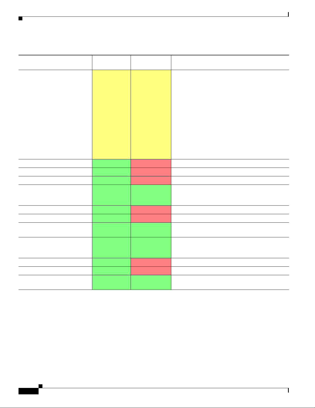
Table 1 -1 lists the features supported by service policy rules.
Cisco ASA Series Firewall ASDM Configuration Guide
1-1
Page 28
Information About Service Policies
Table 1-1 Service Policy Rule Features
Chapter 1 Configuring a Service Policy
Feature
Application inspection (multiple
types)
ASA CSC
ASA IPS
ASA CX
NetFlow Secure Event Logging
filtering
QoS input and output policing
QoS standard priority queue
QoS traffic shaping, hierarchical
priority queue
TCP and UDP connection limits
and timeouts, and TCP sequence
number randomization
TCP normalization
TCP state bypass
User statistics for Identity
Firewall
For Through
Traffic?
All except
RADIUS
accounting
For Management
Traffic? See:
RADIUS
• Chapter 10, “Getting Started with Application
accounting only
• Chapter 11, “Configuring Inspection of Basic
Layer Protocol Inspection.”
Internet Protocols.”
• Chapter 12, “Configuring Inspection for Voice
and Video Protocols.”
• Chapter 13, “Configuring Inspection of Database
and Directory Protocols.”
• Chapter 14, “Configuring Inspection for
Management Application Protocols.”
• Chapter 25, “Configuring the ASA for Cisco
Cloud Web Security.”
Ye s No Chapter 32, “Configuring the ASA CSC Module.”
Ye s No Chapter 31, “Configuring the ASA IPS Module.”
Ye s No Chapter 30, “Configuring the ASA CX Module.”
Ye s Ye s Chapter 43, “Configuring NetFlow Secure Event
Logging (NSEL),” in the general operations
configuration guide.
Ye s No Chapter 23, “Configuring QoS.”
Ye s No Chapter 23, “Configuring QoS.”
Ye s Ye s Chapter 23, “Configuring QoS.”
Ye s Ye s Chapter 22, “Configuring Connection Settings.”
Ye s No Chapter 22, “Configuring Connection Settings.”
Ye s No Chapter 22, “Configuring Connection Settings.”
Ye s Ye s See the user-statistics command in the command
reference.
Feature Directionality
Actions are applied to traffic bidirectionally or unidirectionally depending on the feature. For features
that are applied bidirectionally, all traffic that enters or exits the interface to which you apply the policy
map is affected if the traffic matches the class map for both directions.
Cisco ASA Series Firewall ASDM Configuration Guide
1-2
Page 29

Chapter 1 Configuring a Service Policy
Note When you use a global policy, all features are unidirectional; features that are normally bidirectional
when applied to a single interface only apply to the ingress of each interface when applied globally.
Because the policy is applied to all interfaces, the policy will be applied in both directions so
bidirectionality in this case is redundant.
For features that are applied unidirectionally, for example QoS priority queue, only traffic that enters (or
exits, depending on the feature) the interface to which you apply the policy map is affected. See
Table 1 -2 for the directionality of each feature.
Table 1-2 Feature Directionality
Feature Single Interface Direction Global Direction
Application inspection (multiple types) Bidirectional Ingress
ASA CSC Bidirectional Ingress
ASA CX Bidirectional Ingress
ASA CX authentication proxy Ingress Ingress
ASA IPS Bidirectional Ingress
NetFlow Secure Event Logging filtering N/A Ingress
QoS input policing Ingress Ingress
QoS output policing Egress Egress
QoS standard priority queue Egress Egress
QoS traffic shaping, hierarchical priority
queue
TCP and UDP connection limits and timeouts,
and TCP sequence number randomization
TCP normalization Bidirectional Ingress
TCP state bypass Bidirectional Ingress
User statistics for Identity Firewall Bidirectional Ingress
Information About Service Policies
Egress Egress
Bidirectional Ingress
Feature Matching Within a Service Policy
See the following information for how a packet matches rules in a policy for a given interface:
1. A packet can match only one rule for an interface for each feature type.
2. When the packet matches a rule for a feature type, the ASA does not attempt to match it to any
subsequent rules for that feature type.
3. If the packet matches a subsequent rule for a different feature type, however, then the ASA also
applies the actions for the subsequent rule, if supported. See the “Incompatibility of Certain Feature
Actions” section on page 1-5 for more information about unsupported combinations.
Note Application inspection includes multiple inspection types, and most are mutually exclusive.
For inspections that can be combined, each inspection is considered to be a separate feature.
Cisco ASA Series Firewall ASDM Configuration Guide
1-3
Page 30

Information About Service Policies
For example, if a packet matches a rule for connection limits, and also matches a rule for an application
inspection, then both actions are applied.
If a packet matches a rulefor HTTP inspection, but also matches another rule that includes HTTP
inspection, then the second rule actions are not applied.
If a packet matches a rulefor HTTP inspection, but also matches another rule that includes FTP
inspection, then the second rule actions are not applied because HTTP and FTP inspections cannpt be
combined.
If a packet matches a rule for HTTP inspection, but also matches another rule that includes IPv6
inspection, then both actions are applied because the IPv6 inspection can be combined with any other
type of inspection.
Order in Which Multiple Feature Actions are Applied
The order in which different types of actions in a service policy are performed is independent of the order
in which the actions appear in the table.
Chapter 1 Configuring a Service Policy
Note NetFlow Secure Event Logging filtering and User statistics for Identity Firewall are order-independent.
Actions are performed in the following order:
1. QoS input policing
2. TCP normalization, TCP and UDP connection limits and timeouts, TCP sequence number
randomization, and TCP state bypass.
Note When a the ASA performs a proxy service (such as AAA or CSC) or it modifies the TCP payload
(such as FTP inspection), the TCP normalizer acts in dual mode, where it is applied before and
after the proxy or payload modifying service.
3. ASA CSC
4. Application inspections that can be combined with other inspections:
a. IPv6
b. IP options
c. WAAS
5. Application inspections that cannot be combined with other inspections. See the “Incompatibility of
Certain Feature Actions” section on page 1-5 for more information.
6. ASA IPS
7. ASA CX
1-4
8. QoS output policing
9. QoS standard priority queue
10. QoS traffic shaping, hierarchical priority queue
Cisco ASA Series Firewall ASDM Configuration Guide
Page 31

Chapter 1 Configuring a Service Policy
Incompatibility of Certain Feature Actions
Some features are not compatible with each other for the same traffic. The following list may not include
all incompatibilities; for information about compatibility of each feature, see the chapter or section for
your feature:
• You cannot configure QoS priority queueing and QoS policing for the same set of traffic.
• Most inspections should not be combined with another inspection, so the ASA only applies one
inspection if you configure multiple inspections for the same traffic. HTTP inspection can be
combined with the Cloud Web Security inspection. Other exceptions are listed in the “Order in
Which Multiple Feature Actions are Applied” section on page 1-4.
• You cannot configure traffic to be sent to multiple modules, such as the ASA CX and ASA IPS.
• HTTP inspection is not compatible with the ASA CX.
• The ASA CX is not compatible with Cloud Web Security.
Note The Default Inspection Traffic traffic class, which is used in the default global policy, is a special CLI
shortcut to match the default ports for all inspections. When used in a policy map, this class map ensures
that the correct inspection is applied to each packet, based on the destination port of the traffic. For
example, when UDP traffic for port 69 reaches the ASA, then the ASA applies the TFTP inspection;
when TCP traffic for port 21 arrives, then the ASA applies the FTP inspection. So in this case only, you
can configure multiple inspections for the same class map. Normally, the ASA does not use the port
number to determine which inspection to apply, thus giving you the flexibility to apply inspections to
non-standard ports, for example.
Licensing Requirements for Service Policies
This traffic class does not include the default ports for Cloud Web Security inspection (80 and 443).
Feature Matching for Multiple Service Policies
For TCP and UDP traffic (and ICMP when you enable stateful ICMP inspection), service policies
operate on traffic flows, and not just individual packets. If traffic is part of an existing connection that
matches a feature in a policy on one interface, that traffic flow cannot also match the same feature in a
policy on another interface; only the first policy is used.
For example, if HTTP traffic matches a policy on the inside interface to inspect HTTP traffic, and you
have a separate policy on the outside interface for HTTP inspection, then that traffic is not also inspected
on the egress of the outside interface. Similarly, the return traffic for that connection will not be
inspected by the ingress policy of the outside interface, nor by the egress policy of the inside interface.
For traffic that is not treated as a flow, for example ICMP when you do not enable stateful ICMP
inspection, returning traffic can match a different policy map on the returning interface. For example, if
you configure IPS on the inside and outside interfaces, but the inside policy uses virtual sensor 1 while
the outside policy uses virtual sensor 2, then a non-stateful Ping will match virtual sensor 1 outbound,
but will match virtual sensor 2 inbound.
Licensing Requirements for Service Policies
Cisco ASA Series Firewall ASDM Configuration Guide
1-5
Page 32

Guidelines and Limitations
Model License Requirement
All models Base License.
Guidelines and Limitations
This section includes the guidelines and limitations for this feature.
Context Mode Guidelines
Supported in single and multiple context mode.
Firewall Mode Guidelines
Supported in routed and transparent firewall mode.
IPv6 Guidelines
Supports IPv6 for the following features:
• Application inspection for DNS, FTP, HTTP, ICMP, ScanSafe, SIP, SMTP, IPsec-pass-thru, and
IPv6.
Chapter 1 Configuring a Service Policy
• ASA IPS
• ASA CX
• NetFlow Secure Event Logging filtering
• TCP and UDP connection limits and timeouts, TCP sequence number randomization
• TCP normalization
• TCP state bypass
• User statistics for Identity Firewall
Traffic Class Guidelines
The maximum number of traffic classes of all types is 255 in single mode or per context in multiple
mode. Class maps include the following types:
• Layer 3/4 class maps (for through traffic and management traffic).
• Inspection class maps
• Regular expression class maps
• match commands used directly underneath an inspection policy map
This limit also includes default traffic classes of all types, limiting user-configured traffic classes to
approximately 235. See the “Default Traffic Classes” section on page 1-8.
Service Policy Guidelines
• Interface service policies take precedence over the global service policy for a given feature. For
example, if you have a global policy with FTP inspection, and an interface policy with TCP
normalization, then both FTP inspection and TCP normalization are applied to the interface.
However, if you have a global policy with FTP inspection, and an interface policy with FTP
inspection, then only the interface policy FTP inspection is applied to that interface.
1-6
Cisco ASA Series Firewall ASDM Configuration Guide
Page 33

Chapter 1 Configuring a Service Policy
• You can only apply one global policy. For example, you cannot create a global policy that includes
feature set 1, and a separate global policy that includes feature set 2. All features must be included
in a single policy.
• When you make service policy changes to the configuration, all new connections use the new service
policy. Existing connections continue to use the policy that was configured at the time of the
connection establishment. show command output will not include data about the old connections.
For example, if you remove a QoS service policy from an interface, then re-add a modified version,
then the show service-policy command only displays QoS counters associated with new
connections that match the new service policy; existing connections on the old policy no longer
show in the command output.
To ensure that all connections use the new policy, you need to disconnect the current connections so
they can reconnect using the new policy. See the clear conn or clear local-host commands.
Default Settings
The following topics describe the default settings for Modular Policy Framework:
Default Settings
• Default Configuration, page 1-7
• Default Traffic Classes, page 1-8
Default Configuration
By default, the configuration includes a policy that matches all default application inspection traffic and
applies certain inspections to the traffic on all interfaces (a global policy). Not all inspections are enabled
by default. You can only apply one global policy, so if you want to alter the global policy, you need to
either edit the default policy or disable it and apply a new one. (An interface policy overrides the global
policy for a particular feature.)
The default policy includes the following application inspections:
• DNS
• FTP
• H323 (H225)
• H323 (RAS)
• RSH
• RT SP
• ESMTP
• SQLnet
• Skinny (SCCP)
• SunRPC
• XDMCP
• SIP
• NetBios
• TFTP
Cisco ASA Series Firewall ASDM Configuration Guide
1-7
Page 34

Task Flows for Configuring Service Policies
• IP Options
Default Traffic Classes
The configuration includes a default traffic class that the ASA uses in the default global policy called
Default Inspection Traffic; it matches the default inspection traffic. This class, which is used in the
default global policy, is a special shortcut to match the default ports for all inspections. When used in a
policy, this class ensures that the correct inspection is applied to each packet, based on the destination
port of the traffic. For example, when UDP traffic for port 69 reaches the ASA, then the ASA applies the
TFTP inspection; when TCP traffic for port 21 arrives, then the ASA applies the FTP inspection. So in
this case only, you can configure multiple inspections for the same class map. Normally, the ASA does
not use the port number to determine which inspection to apply, thus giving you the flexibility to apply
inspections to non-standard ports, for example.
Another class map that exists in the default configuration is called class-default, and it matches all
traffic. You can use the class-default class if desired, rather than using the Any traffic class. In fact, some
features are only available for class-default, such as QoS traffic shaping.
Chapter 1 Configuring a Service Policy
Task Flows for Configuring Service Policies
This section includes the following topics:
• Task Flow for Configuring a Service Policy Rule, page 1-8
Task Flow for Configuring a Service Policy Rule
Configuring a service policy consists of adding one or more service policy rules per interface or for the
global policy. For each rule, you identify the following elements:
Step 1 Identify the interface to which you want to apply the rule, or identify the global policy.
Step 2 Identify the traffic to which you want to apply actions. You can identify Layer 3 and 4 through traffic.
Step 3 Apply actions to the traffic class. You can apply multiple actions for each traffic class.
Adding a Service Policy Rule for Through Traffic
See the “Supported Features” section on page 1-1 for more information. To add a service policy rule for
through traffic, perform the following steps:
1-8
Step 1 Choose Configuration > Firewall > Service Policy Rules pane, and click Add.
The Add Service Policy Rule Wizard - Service Policy dialog box appears.
Cisco ASA Series Firewall ASDM Configuration Guide
Page 35

Chapter 1 Configuring a Service Policy
Adding a Service Policy Rule for Through Traffic
Note When you click the Add button, and not the small arrow on the right of the Add button, you add
a through traffic rule by default. If you click the arrow on the Add button, you can choose
between a through traffic rule and a management traffic rule.
Step 2 In the Create a Service Policy and Apply To area, click one of the following options:
• Interface. This option applies the service policy to a single interface. Interface service policies take
precedence over the global service policy for a given feature. For example, if you have a global
policy with FTP inspection, and an interface policy with TCP connection limits, then both FTP
inspection and TCP connection limits are applied to the interface. However, if you have a global
policy with FTP inspection, and an interface policy with FTP inspection, then only the interface
policy FTP inspection is applied to that interface.
a. Choose an interface from the drop-down list.
If you choose an interface that already has a policy, then the wizard lets you add a new service
policy rule to the interface.
b. If it is a new service policy, enter a name in the Policy Name field.
c. (Optional) Enter a description in the Description field.
d. (Optional) Check the Drop and log unsupported IPv6 to IPv6 traffic check box to generate a
syslog (767001) for IPv6 traffic that is dropped by application inspections that do not support
IPv6 traffic. By default, syslogs are not generated. For a list of inspections that support IPv6,
see the “IPv6 Guidelines” section on page 1-6.
Cisco ASA Series Firewall ASDM Configuration Guide
1-9
Page 36

Adding a Service Policy Rule for Through Traffic
• Global - applies to all interfaces. This option applies the service policy globally to all interfaces.
By default, a global policy exists that includes a service policy rule for default application
inspection. See the “Default Settings” section on page 1-7 for more information. You can add a rule
to the global policy using the wizard.
a. If it is a new service policy, enter a name in the Policy Name field.
b. (Optional) Enter a description in the Description field.
c. (Optional) Check the Drop and log unsupported IPv6 to IPv6 traffic check box to generate a
syslog (767001) for IPv6 traffic that is dropped by application inspections that do not support
IPv6 traffic. By default, syslogs are not generated. For a list of inspections that support IPv6,
see the “IPv6 Guidelines” section on page 1-6.
Step 3 Click Next.
The Add Service Policy Rule Wizard - Traffic Classification Criteria dialog box appears.
Step 4 Click one of the following options to specify the traffic to which to apply the policy actions:
• Create a new traffic class. Enter a traffic class name in the Create a new traffic class field, and enter
an optional description.
Identify the traffic using one of several criteria:
–
Default Inspection Traffic—The class matches the default TCP and UDP ports used by all
applications that the ASA can inspect.
This option, which is used in the default global policy, is a special shortcut that when used in a
rule, ensures that the correct inspection is applied to each packet, based on the destination port
of the traffic. For example, when UDP traffic for port 69 reaches the ASA, then the ASA applies
the TFTP inspection; when TCP traffic for port 21 arrives, then the ASA applies the FTP
inspection. So in this case only, you can configure multiple inspections for the same rule (See
the “Incompatibility of Certain Feature Actions” section on page 1-5 for more information
about combining actions). Normally, the ASA does not use the port number to determine the
inspection applied, thus giving you the flexibility to apply inspections to non-standard ports, for
example.
Chapter 1 Configuring a Service Policy
1-10
See the “Default Settings and NAT Limitations” section on page 10-4 for a list of default ports.
The ASA includes a default global policy that matches the default inspection traffic, and applies
common inspections to the traffic on all interfaces. Not all applications whose ports are included
in the Default Inspection Traffic class are enabled by default in the policy map.
You can specify a Source and Destination IP Address (uses ACL) class along with the Default
Inspection Traffic class to narrow the matched traffic. Because the Default Inspection Traffic
class specifies the ports and protocols to match, any ports and protocols in the ACL are ignored.
–
Source and Destination IP Address (uses ACL)—The class matches traffic specified by an
extended ACL. If the ASA is operating in transparent firewall mode, you can use an EtherType
ACL.
Note When you create a new traffic class of this type, you can only specify one access control
entry (ACE) initially. After you finish adding the rule, you can add additional ACEs by
adding a new rule to the same interface or global policy, and then specifying Add rule
to existing traffic class on the Traffic Classification dialog box (see below).
–
Tunnel Group—The class matches traffic for a tunnel group to which you want to apply QoS.
You can also specify one other traffic match option to refine the traffic match, excluding Any
Traffic, Source and Destination IP Address (uses ACL), or Default Inspection Traffic.
Cisco ASA Series Firewall ASDM Configuration Guide
Page 37

Chapter 1 Configuring a Service Policy
–
TCP or UDP Destination Port—The class matches a single port or a contiguous range of ports.
Tip For applications that use multiple, non-contiguous ports, use the Source and Destination IP
Address (uses ACL) to match each port.
–
RTP Range—The class map matches RTP traffic.
–
IP DiffServ CodePoints (DSCP)—The class matches up to eight DSCP values in the IP header.
–
IP Precedence—The class map matches up to four precedence values, represented by the TOS
byte in the IP header.
–
Any Traffic—Matches all traffic.
• Add rule to existing traffic class. If you already have a service policy rule on the same interface,
or you are adding to the global service policy, this option lets you add an ACE to an existing ACL.
You can add an ACE to any ACL that you previously created when you chose the Source and
Destination IP Address (uses ACL) option for a service policy rule on this interface. For this traffic
class, you can have only one set of rule actions even if you add multiple ACEs. You can add multiple
ACEs to the same traffic class by repeating this entire procedure. See the “Managing the Order of
Service Policy Rules” section on page 1-15 for information about changing the order of ACEs.
Adding a Service Policy Rule for Through Traffic
• Use an existing traffic class. If you created a traffic class used by a rule on a different interface,
you can reuse the traffic class definition for this rule. Note that if you alter the traffic class for one
rule, the change is inherited by all rules that use that traffic class. If your configuration includes any
class-map commands that you entered at the CLI, those traffic class names are also available
(although to view the definition of the traffic class, you need to create the rule).
• Use class default as the traffic class. This option uses the class-default class, which matches all
traffic. The class-default class is created automatically by the ASA and placed at the end of the
policy. If you do not apply any actions to it, it is still created by the ASA, but for internal purposes
only. You can apply actions to this class, if desired, which might be more convenient than creating
a new traffic class that matches all traffic. You can only create one rule for this service policy using
the class-default class, because each traffic class can only be associated with a single rule per service
policy.
Step 5 Click Next.
Step 6 The next dialog box depends on the traffic match criteria you chose.
Note The Any Traffic option does not have a special dialog box for additional configuration.
• Default Inspections—This dialog box is informational only, and shows the applications and the ports
that are included in the traffic class.
• Source and Destination Address—This dialog box lets you set the source and destination addresses:
a. Click Match or Do Not Match.
The Match option creates a rule where traffic matching the addresses have actions applied. The
Do Not Match option exempts the traffic from having the specified actions applied. For
example, you want to match all traffic in 10.1.1.0/24 and apply connection limits to it, except
for 10.1.1.25. In this case, create two rules, one for 10.1.1.0/24 using the Match option and one
for 10.1.1.25 using the Do Not Match option. Be sure to arrange the rules so that the Do Not
Match rule is above the Match rule, or else 10.1.1.25 will match the Match rule first.
b. In the Source field, enter the source IP address, or click the ... button to choose an IP address
that you already defined in ASDM.
Cisco ASA Series Firewall ASDM Configuration Guide
1-11
Page 38

Adding a Service Policy Rule for Through Traffic
Specify the address and subnet mask using prefix/length notation, such as 10.1.1.0/24. If you
enter an IP address without a mask, it is considered to be a host address, even if it ends with a 0.
Enter any to specify any source address.
Separate multiple addresses by a comma.
c. In the Destination field, enter the destination IP address, or click the ... button to choose an IP
address that you already defined in ASDM.
Specify the address and subnet mask using prefix/length notation, such as 10.1.1.0/24. If you
enter an IP address without a mask, it is considered to be a host address, even if it ends with a 0.
Enter any to specify any destination address.
Separate multiple addresses by a comma.
d. In the Service field, enter an IP service name or number for the destination service, or click the
... button to choose a service.
If you want to specify a TCP or UDP port number, or an ICMP service number, enter
protocol/port. For example, enter TCP/8080.
By default, the service is IP.
Separate multiple services by a comma.
Chapter 1 Configuring a Service Policy
e. (Optional) Enter a description in the Description field.
f. (Optional) To specify a source service for TCP or UDP, click the More Options area open, and
enter a TCP or UDP service in the Source Service field.
The destination service and source service must be the same. Copy and paste the destination
Service field to the Source Service field.
g. (Optional) To make the rule inactive, click the More Options area open, and uncheck Enable
Rule.
This setting might be useful if you do not want to remove the rule, but want to turn it off.
h. (Optional) To set a time range for the rule, click the More Options area open, and from the Time
Range drop-down list, choose a time range.
To add a new time range, click the ... button. See the “Configuring Time Ranges” section on
page 20-15 in the general operations configuration guide for more information.
This setting might be useful if you only want the rule to be active at predefined times.
• Tunnel Group—Choose a tunnel group from the Tunnel Group drop-down list, or click New to add
a new tunnel group. See the “Add or Edit an IPsec Remote Access Connection Profile” section on
page 4-79 in the VPN configuration guide for more information.
To police each flow, check Match flow destination IP address. All traffic going to a unique IP
destination address is considered a flow.
• Destination Port—Click TCP or UDP.
In the Service field, enter a port number or name, or click ... to choose one already defined in ASDM.
• RTP Range—Enter an RTP port range, between 2000 and 65534. The maximum number of port sin
the range is 16383.
• IP DiffServ CodePoints (DSCP)—In the DSCP Value to Add area, choose a value from the Select
Named DSCP Values or enter a value in the Enter DSCP Value (0-63) field, and click Add.
1-12
Add additional values as desired, or remove them using the Remove button.
• IP Precedence—From the Available IP Precedence area, choose a value and click Add.
Cisco ASA Series Firewall ASDM Configuration Guide
Page 39

Chapter 1 Configuring a Service Policy
Adding a Service Policy Rule for Management Traffic
Add additional values as desired, or remove them using the Remove button.
Step 7 Click Next.
The Add Service Policy Rule - Rule Actions dialog box appears.
Step 8 Configure one or more rule actions. See the “Supported Features” section on page 1-1 for a list of
features.
Step 9 Click Finish.
Adding a Service Policy Rule for Management Traffic
You can create a service policy for traffic directed to the ASA for management purposes. See the
“Supported Features” section on page 1-1 for more information. This section includes the following
topics:
Configuring a Service Policy Rule for Management Traffic
To add a service policy rule for management traffic, perform the following steps:
Step 1 From the Configuration > Firewall > Service Policy Rules pane, click the down arrow next to Add.
Step 2 Choose Add Management Service Policy Rule.
The Add Management Service Policy Rule Wizard - Service Policy dialog box appears.
Step 3 In the Create a Service Policy and Apply To area, click one of the following options:
• Interface. This option applies the service policy to a single interface. Interface service policies take
precedence over the global service policy for a given feature. For example, if you have a global
policy with RADIUS accounting inspection, and an interface policy with connection limits, then
both RADIUS accounting and connection limits are applied to the interface. However, if you have
a global policy with RADIUS accounting, and an interface policy with RADIUS accounting, then
only the interface policy RADIUS accounting is applied to that interface.
a. Choose an interface from the drop-down list.
If you choose an interface that already has a policy, then the wizard lets you add a new service
policy rule to the interface.
b. If it is a new service policy, enter a name in the Policy Name field.
c. (Optional) Enter a description in the Description field.
• Global - applies to all interfaces. This option applies the service policy globally to all interfaces.
By default, a global policy exists that includes a service policy rule for default application
inspection. See the “Default Settings” section on page 1-7 for more information. You can add a rule
to the global policy using the wizard.
Step 4 Click Next.
The Add Management Service Policy Rule Wizard - Traffic Classification Criteria dialog box appears.
Step 5 Click one of the following options to specify the traffic to which to apply the policy actions:
• Create a new traffic class. Enter a traffic class name in the Create a new traffic class field, and enter
an optional description.
Cisco ASA Series Firewall ASDM Configuration Guide
1-13
Page 40

Adding a Service Policy Rule for Management Traffic
Identify the traffic using one of several criteria:
–
Source and Destination IP Address (uses ACL)—The class matches traffic specified by an
extended ACL. If the ASA is operating in transparent firewall mode, you can use an EtherType
ACL.
Note When you create a new traffic class of this type, you can only specify one access control
entry (ACE) initially. After you finish adding the rule, you can add additional ACEs by
adding a new rule to the same interface or global policy, and then specifying Add rule
to existing traffic class on the Traffic Classification dialog box (see below).
–
TCP or UDP Destination Port—The class matches a single port or a contiguous range of ports.
Tip For applications that use multiple, non-contiguous ports, use the Source and Destination IP
Address (uses ACL) to match each port.
• Add rule to existing traffic class. If you already have a service policy rule on the same interface,
or you are adding to the global service policy, this option lets you add an ACE to an existing ACL.
You can add an ACE to any ACL that you previously created when you chose the Source and
Destination IP Address (uses ACL) option for a service policy rule on this interface. For this traffic
class, you can have only one set of rule actions even if you add multiple ACEs. You can add multiple
ACEs to the same traffic class by repeating this entire procedure. See the “Managing the Order of
Service Policy Rules” section on page 1-15 for information about changing the order of ACEs.
• Use an existing traffic class. If you created a traffic class used by a rule on a different interface,
you can reuse the traffic class definition for this rule. Note that if you alter the traffic class for one
rule, the change is inherited by all rules that use that traffic class. If your configuration includes any
class-map commands that you entered at the CLI, those traffic class names are also available
(although to view the definition of the traffic class, you need to create the rule).
Chapter 1 Configuring a Service Policy
Step 6 Click Next.
Step 7 The next dialog box depends on the traffic match criteria you chose.
• Source and Destination Address—This dialog box lets you set the source and destination addresses:
a. Click Match or Do Not Match.
The Match option creates a rule where traffic matching the addresses have actions applied. The
Do Not Match option exempts the traffic from having the specified actions applied. For
example, you want to match all traffic in 10.1.1.0/24 and apply connection limits to it, except
for 10.1.1.25. In this case, create two rules, one for 10.1.1.0/24 using the Match option and one
for 10.1.1.25 using the Do Not Match option. Be sure to arrange the rules so that the Do Not
Match rule is above the Match rule, or else 10.1.1.25 will match the Match rule first.
b. In the Source field, enter the source IP address, or click the ... button to choose an IP address
that you already defined in ASDM.
Specify the address and subnet mask using prefix/length notation, such as 10.1.1.0/24. If you
enter an IP address without a mask, it is considered to be a host address, even if it ends with a 0.
Enter any to specify any source address.
Separate multiple addresses by a comma.
c. In the Destination field, enter the destination IP address, or click the ... button to choose an IP
address that you already defined in ASDM.
1-14
Cisco ASA Series Firewall ASDM Configuration Guide
Page 41

Chapter 1 Configuring a Service Policy
Specify the address and subnet mask using prefix/length notation, such as 10.1.1.0/24. If you
enter an IP address without a mask, it is considered to be a host address, even if it ends with a 0.
Enter any to specify any destination address.
Separate multiple addresses by a comma.
d. In the Service field, enter an IP service name or number for the destination service, or click the
... button to choose a service.
If you want to specify a TCP or UDP port number, or an ICMP service number, enter
protocol/port. For example, enter TCP/8080.
By default, the service is IP.
Separate multiple services by a comma.
e. (Optional) Enter a description in the Description field.
f. (Optional) To specify a source service for TCP or UDP, click the More Options area open, and
enter a TCP or UDP service in the Source Service field.
The destination service and source service must be the same. Copy and paste the destination
Service field to the Source Service field.
g. (Optional) To make the rule inactive, click the More Options area open, and uncheck Enable
Rule.
Managing the Order of Service Policy Rules
This setting might be useful if you do not want to remove the rule, but want to turn it off.
h. (Optional) To set a time range for the rule, click the More Options area open, and from the Time
Range drop-down list, choose a time range.
To add a new time range, click the ... button. See the “Configuring Time Ranges” section on
page 20-15 in the general operations configuration guide for more information.
This setting might be useful if you only want the rule to be active at predefined times.
• Destination Port—Click TCP or UDP.
In the Service field, enter a port number or name, or click ... to choose one already defined in ASDM.
Step 8 Click Next.
The Add Management Service Policy Rule - Rule Actions dialog box appears.
Step 9 To configure RADIUS accounting inspection, choose an inspect map from the RADIUS Accounting
Map drop-down list, or click Configure to add a map.
See the “Supported Features” section on page 1-1 for more information.
Step 10 To configure connection settings, see the “Configuring Connection Settings” section on page 22-8.
Step 11 Click Finish.
Managing the Order of Service Policy Rules
The order of service policy rules on an interface or in the global policy affects how actions are applied
to traffic. See the following guidelines for how a packet matches rules in a service policy:
• A packet can match only one rule in a service policy for each feature type.
• When the packet matches a rule that includes actions for a feature type, the ASA does not attempt
to match it to any subsequent rules including that feature type.
Cisco ASA Series Firewall ASDM Configuration Guide
1-15
Page 42
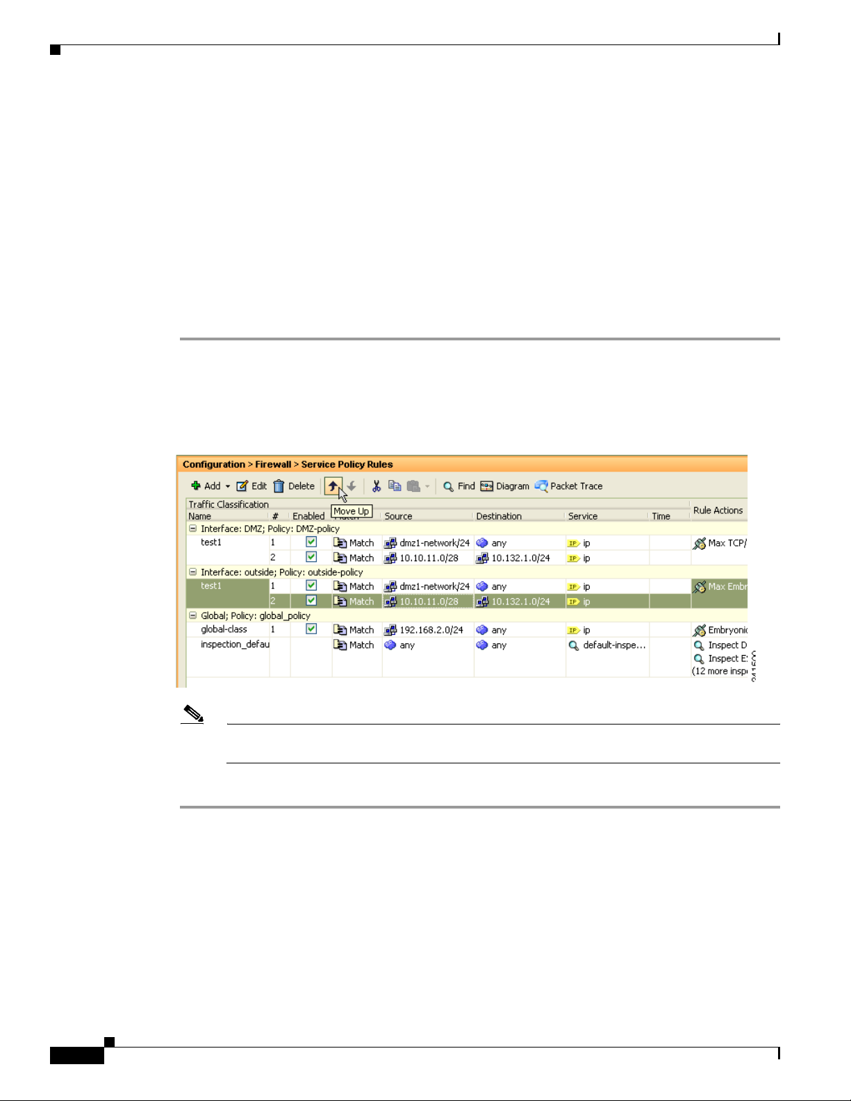
Managing the Order of Service Policy Rules
• If the packet matches a subsequent rule for a different feature type, however, then the ASA also
applies the actions for the subsequent rule.
For example, if a packet matches a rule for connection limits, and also matches a rule for application
inspection, then both rule actions are applied.
If a packet matches a rule for application inspection, but also matches another rule that includes
application inspection, then the second rule actions are not applied.
If your rule includes an ACL with multiple ACEs, then the order of ACEs also affects the packet flow.
The ASA tests the packet against each ACE in the order in which the entries are listed. After a match is
found, no more ACEs are checked. For example, if you create an ACE at the beginning of an ACL that
explicitly permits all traffic, no further statements are ever checked.
To change the order of rules or ACEs within a rule, perform the following steps:
Step 1 From the Configuration > Firewall > Service Policy Rules pane, choose the rule or ACE that you want
to move up or down.
Step 2 Click the Move Up or Move Down cursor (see Figure 1-1).
Figure 1-1 Moving an ACE
Chapter 1 Configuring a Service Policy
1-16
Note If you rearrange ACEs in an ACL that is used in multiple service policies, then the change is
inherited in all service policies.
Step 3 When you are done rearranging your rules or ACEs, click Apply.
Cisco ASA Series Firewall ASDM Configuration Guide
Page 43

Chapter 1 Configuring a Service Policy
Feature History for Service Policies
Feature History for Service Policies
Table 1 -3 lists the release history for this feature.
Table 1-3 Feature History for Service Policies
Feature Name Releases Feature Information
Modular Policy Framework 7.0(1) Modular Policy Framework was introduced.
Management class map for use with RADIUS
accounting traffic
Inspection policy maps 7.2(1) The inspection policy map was introduced. The following
Regular expressions and policy maps 7.2(1) Regular expressions and policy maps were introduced to be
Match any for inspection policy maps 8.0(2) The match any keyword was introduced for use with
7.2(1) The management class map was introduced for use with
RADIUS accounting traffic. The following commands were
introduced: class-map type management, and inspect
radius-accounting.
command was introduced: class-map type inspect.
used under inspection policy maps. The following
commands were introduced: class-map type regex, regex,
match regex.
inspection policy maps: traffic can match one or more
criteria to match the class map. Formerly, only match all
was available.
Cisco ASA Series Firewall ASDM Configuration Guide
1-17
Page 44

Feature History for Service Policies
Chapter 1 Configuring a Service Policy
1-18
Cisco ASA Series Firewall ASDM Configuration Guide
Page 45

CHA PTER
2
Configuring Special Actions for Application Inspections (Inspection Policy Map)
Modular Policy Framework lets you configure special actions for many application inspections. When
you enable an inspection engine in the service policy, you can also optionally enable actions as defined
in an inspection policy map. When the inspection policy map matches traffic within the service policy
for which you have defined an inspection action, then that subset of traffic will be acted upon as specified
(for example, dropped or rate-limited).
This chapter includes the following sections:
• Information About Inspection Policy Maps, page 2-1
• Guidelines and Limitations, page 2-2
• Default Inspection Policy Maps, page 2-2
• Defining Actions in an Inspection Policy Map, page 2-3
• Identifying Traffic in an Inspection Class Map, page 2-3
• Where to Go Next, page 2-4
• Feature History for Inspection Policy Maps, page 2-4
Information About Inspection Policy Maps
See the “Configuring Application Layer Protocol Inspection” section on page 10-7 for a list of
applications that support inspection policy maps.
An inspection policy map consists of one or more of the following elements. The exact options available
for an inspection policy map depends on the application.
• Traffic matching option—You can define a traffic matching option directly in the inspection policy
map to match application traffic to criteria specific to the application, such as a URL string, for
which you then enable actions.
–
Some traffic matching options can specify regular expressions to match text inside a packet. Be
sure to create and test the regular expressions before you configure the policy map, either singly
or grouped together in a regular expression class map.
• Inspection class map—An inspection class map includes multiple traffic matching options. You then
identify the class map in the policy map and enable actions for the class map as a whole. The
difference between creating a class map and defining the traffic match directly in the inspection
Cisco ASA Series Firewall ASDM Configuration Guide
2-1
Page 46

Chapter 2 Configuring Special Actions for Application Inspections (Inspection Policy Map)
Guidelines and Limitations
policy map is that you can create more complex match criteria and you can reuse class maps.
However, you cannot set different actions for different matches. Note: Not all inspections support
inspection class maps.
• Parameters—Parameters affect the behavior of the inspection engine.
Guidelines and Limitations
• HTTP inspection policy maps—If you modify an in-use HTTP inspection policy map, you must
remove and reapply the inspection policy map action for the changes to take effect. For example, if
you modify the “http-map” inspection policy map, you must remove, apply changes, and readd the
inspection policy map to the service policy.
• All inspection policy maps—If you want to exchange an in-use inspection policy map for a different
map name, you must remove, apply changes, and readd the new inspection policy map to the service
policy.
• You can specify multiple inspection class maps or direct matches in the inspection policy map.
If a packet matches multiple different matches, then the order in which the ASA applies the actions
is determined by internal ASA rules, and not by the order they are added to the inspection policy
map. The internal rules are determined by the application type and the logical progression of parsing
a packet, and are not user-configurable. For example for HTTP traffic, parsing a Request Method
field precedes parsing the Header Host Length field; an action for the Request Method field occurs
before the action for the Header Host Length field.
If an action drops a packet, then no further actions are performed in the inspection policy map. For
example, if the first action is to reset the connection, then it will never match any further match
criteria. If the first action is to log the packet, then a second action, such as resetting the connection,
can occur.
If a packet matches multiple match criteria that are the same, then they are matched in the order they
appear in the policy map.
A class map is determined to be the same type as another class map or direct match based on the
lowest priority match option in the class map (the priority is based on the internal rules). If a class
map has the same type of lowest priority match option as another class map, then the class maps are
matched according to the order they are added to the policy map. If the lowest priority match for
each class map is different, then the class map with the higher priority match option is matched first.
Default Inspection Policy Maps
DNS inspection is enabled by default, using the preset_dns_map inspection class map:
• The maximum DNS message length is 512 bytes.
• The maximum client DNS message length is automatically set to match the Resource Record.
• DNS Guard is enabled, so the ASA tears down the DNS session associated with a DNS query as
soon as the DNS reply is forwarded by the ASA. The ASA also monitors the message exchange to
ensure that the ID of the DNS reply matches the ID of the DNS query.
• Translation of the DNS record based on the NAT configuration is enabled.
• Protocol enforcement is enabled, which enables DNS message format check, including domain
name length of no more than 255 characters, label length of 63 characters, compression, and looped
pointer check.
Cisco ASA Series Firewall ASDM Configuration Guide
2-2
Page 47

Chapter 2 Configuring Special Actions for Application Inspections (Inspection Policy Map)
Defining Actions in an Inspection Policy Map
Note There are other default inspection policy maps such as _default_esmtp_map. For example, an ESMTP
inspection rule implicitly uses the policy map “_default_esmtp_map.”
Defining Actions in an Inspection Policy Map
When you enable an inspection engine in the service policy, you can also optionally enable actions as
defined in an inspection policy map.
Detailed Steps
Step 1 (Optional) Create an inspection class map. Alternatively, you can identify the traffic directly within the
policy map. See the “Identifying Traffic in an Inspection Class Map” section on page 2-3.
Step 2 (Optional) For policy map types that support regular expressions, create a regular expression. See the
“Configuring Regular Expressions” section on page 20-11 in the general operations configuration guide.
Step 3 Choose Configuration > Firewall > Objects > Inspect Maps .
Step 4 Choose the inspection type you want to configure.
Step 5 Click Add to add a new inspection policy map.
Step 6 Follow the instructions for your inspection type in the inspection chapter.
Identifying Traffic in an Inspection Class Map
This type of class map allows you to match criteria that is specific to an application. For example, for
DNS traffic, you can match the domain name in a DNS query.
A class map groups multiple traffic matches (in a match-all class map), or lets you match any of a list of
matches (in a match-any class map). The difference between creating a class map and defining the traffic
match directly in the inspection policy map is that the class map lets you group multiple match
commands, and you can reuse class maps. For the traffic that you identify in this class map, you can
specify actions such as dropping, resetting, and/or logging the connection in the inspection policy map.
If you want to perform different actions on different types of traffic, you should identify the traffic
directly in the policy map.
Restrictions
Not all applications support inspection class maps.
Detailed Steps
Step 1 Choose Configuration > Firewall > Objects > Class Maps .
Step 2 Choose the inspection type you want to configure.
Step 3 Click Add to add a new inspection class map.
Cisco ASA Series Firewall ASDM Configuration Guide
2-3
Page 48

Chapter 2 Configuring Special Actions for Application Inspections (Inspection Policy Map)
Where to Go Next
Step 4 Follow the instructions for your inspection type in the inspection chapter.
Where to Go Next
To use an inspection policy, see Chapter 1, “Configuring a Service Policy.”
Feature History for Inspection Policy Maps
Table 2 -1 lists the release history for this feature.
Table 2-1 Feature History for Service Policies
Feature Name Releases Feature Information
Inspection policy maps 7.2(1) The inspection policy map was introduced. The following
command was introduced: class-map type inspect.
Regular expressions and policy maps 7.2(1) Regular expressions and policy maps were introduced to be
used under inspection policy maps. The following
commands were introduced: class-map type regex, regex,
match regex.
Match any for inspection policy maps 8.0(2) The match any keyword was introduced for use with
inspection policy maps: traffic can match one or more
criteria to match the class map. Formerly, only match all
was available.
2-4
Cisco ASA Series Firewall ASDM Configuration Guide
Page 49

P
ART
2
Configuring Network Address Translation
Page 50

Page 51

CHA PTER
3
Information About NAT (ASA 8.3 and Later)
This chapter provides an overview of how Network Address Translation (NAT) works on the ASA. This
chapter includes the following sections:
• Why Use NAT?, page 3-1
• NAT Terminology, page 3-2
• NAT Types, page 3-3
• NAT in Routed and Transparent Mode, page 3-12
• NAT and IPv6, page 3-15
• How NAT is Implemented, page 3-15
• NAT Rule Order, page 3-20
• Routing NAT Packets, page 3-22
• NAT for VPN, page 3-25
• DNS and NAT, page 3-31
• Where to Go Next, page 3-36
Note To start configuring NAT, see Chapter 4, “Configuring Network Object NAT (ASA 8.3 and Later),” or
Chapter 5, “Configuring Twice NAT (ASA 8.3 and Later).”
Why Use NAT?
Each computer and device within an IP network is assigned a unique IP address that identifies the host.
Because of a shortage of public IPv4 addresses, most of these IP addresses are private, not routable
anywhere outside of the private company network. RFC 1918 defines the private IP addresses you can
use internally that should not be advertised:
• 10.0.0.0 through 10.255.255.255
• 172.16.0.0 through 172.31.255.255
• 192.168.0.0 through 192.168.255.255
Cisco ASA Series Firewall ASDM Configuration Guide
3-1
Page 52

NAT Terminology
Note NAT is not required. If you do not configure NAT for a given set of traffic, that traffic will not be
Chapter 3 Information About NAT (ASA 8.3 and Later)
One of the main functions of NAT is to enable private IP networks to connect to the Internet. NAT
replaces a private IP address with a public IP address, translating the private addresses in the internal
private network into legal, routable addresses that can be used on the public Internet. In this way, NAT
conserves public addresses because it can be configured to advertise at a minimum only one public
address for the entire network to the outside world.
Other functions of NAT include:
• Security—Keeping internal IP addresses hidden discourages direct attacks.
• IP routing solutions—Overlapping IP addresses are not a problem when you use NAT.
• Flexibility—You can change internal IP addressing schemes without affecting the public addresses
available externally; for example, for a server accessible to the Internet, you can maintain a fixed IP
address for Internet use, but internally, you can change the server address.
• Translating between IPv4 and IPv6 (Routed mode only) (Version 9.0(1) and later)—If you want to
connect an IPv6 network to an IPv4 network, NAT lets you translate between the two types of
addresses.
translated, but will have all of the security policies applied as normal.
NAT Terminology
This document uses the following terminology:
• Real address/host/network/interface—The real address is the address that is defined on the host,
before it is translated. In a typical NAT scenario where you want to translate the inside network when
it accesses the outside, the inside network would be the “real” network. Note that you can translate
any network connected to the ASA, not just an inside network, Therefore if you configure NAT to
translate outside addresses, “real” can refer to the outside network when it accesses the inside
network.
• Mapped address/host/network/interface—The mapped address is the address that the real address is
translated to. In a typical NAT scenario where you want to translate the inside network when it
accesses the outside, the outside network would be the “mapped” network.
Note During address translation, IP addresses residing on the ASA’s interfaces are not translated.
• Bidirectional initiation—Static NAT allows connections to be initiated bidirectionally, meaning
both to the host and from the host.
• Source and destination NAT—For any given packet, both the source and destination IP addresses are
compared to the NAT rules, and one or both can be translated/untranslated. For static NAT, the rule
is bidirectional, so be aware that “source” and “destination” are used in commands and descriptions
throughout this guide even though a given connection might originate at the “destination” address.
3-2
Cisco ASA Series Firewall ASDM Configuration Guide
Page 53

Chapter 3 Information About NAT (ASA 8.3 and Later)
NAT Types
• NAT Types Overview, page 3-3
• Static NAT, page 3-3
• Dynamic NAT, page 3-8
• Dynamic PAT, page 3-10
• Identity NAT, page 3-12
NAT Types Overview
You can implement NAT using the following methods:
• Static NAT—A consistent mapping between a real and mapped IP address. Allows bidirectional
traffic initiation. See the “Static NAT” section on page 3-3.
• Dynamic NAT—A group of real IP addresses are mapped to a (usually smaller) group of mapped IP
addresses, on a first come, first served basis. Only the real host can initiate traffic. See the “Dynamic
NAT” section on page 3-8.
• Dynamic Port Address Translation (PAT)—A group of real IP addresses are mapped to a single IP
address using a unique source port of that IP address. See the “Dynamic PAT” section on page 3-10.
• Identity NAT—A real address is statically translated to itself, essentially bypassing NAT. You might
want to configure NAT this way when you want to translate a large group of addresses, but then want
to exempt a smaller subset of addresses. See the “Identity NAT” section on page 3-12.
NAT Types
Static NAT
This section describes static NAT and includes the following topics:
• Information About Static NAT, page 3-3
• Information About Static NAT with Port Translation, page 3-4
• Information About One-to-Many Static NAT, page 3-6
• Information About Other Mapping Scenarios (Not Recommended), page 3-7
Information About Static NAT
Static NAT creates a fixed translation of a real address to a mapped address. Because the mapped address
is the same for each consecutive connection, static NAT allows bidirectional connection initiation, both
to and from the host (if an access rule exists that allows it). With dynamic NAT and PAT, on the other
hand, each host uses a different address or port for each subsequent translation, so bidirectional initiation
is not supported.
Cisco ASA Series Firewall ASDM Configuration Guide
3-3
Page 54

NAT Types
10.1.1.1 209.165.201.1
Inside Outside
10.1.1.2 209.165.201.2
130035
Security
Appliance
10.1.1.1:23 209.165.201.1:23
Inside Outside
10.1.1.2:8080 209.165.201.2:80
130044
Security
Appliance
Figure 3-1 shows a typical static NAT scenario. The translation is always active so both real and remote
hosts can initiate connections.
Figure 3-1 Static NAT
Note You can disable bidirectionality if desired.
Information About Static NAT with Port Translation
Chapter 3 Information About NAT (ASA 8.3 and Later)
Static NAT with port translation lets you specify a real and mapped protocol (TCP or UDP) and port.
This section includes the following topics:
• Information About Static NAT with Port Address Translation, page 3-4
• Static NAT with Identity Port Translation, page 3-5
• Static NAT with Port Translation for Non-Standard Ports, page 3-5
• Static Interface NAT with Port Translation, page 3-6
Information About Static NAT with Port Address Translation
When you specify the port with static NAT, you can choose to map the port and/or the IP address to the
same value or to a different value.
Figure 3-2 shows a typical static NAT with port translation scenario showing both a port that is mapped
to itself and a port that is mapped to a different value; the IP address is mapped to a different value in
both cases. The translation is always active so both translated and remote hosts can initiate connections.
Figure 3-2 Typical Static NAT with Port Translation Scenario
3-4
Cisco ASA Series Firewall ASDM Configuration Guide
Page 55

Chapter 3 Information About NAT (ASA 8.3 and Later)
Host
Outside
Inside
Undo Translation
10.1.2.27209.165.201.3:21
Undo Translation
10.1.2.28209.165.201.3:80
Undo Translation
10.1.2.29209.165.201.3:25
FTP server
10.1.2.27
HTTP server
10.1.2.28
SMTP server
10.1.2.29
130031
Note For applications that require application inspection for secondary channels (for example, FTP and VoIP),
the ASA automatically translates the secondary ports.
Static NAT with Identity Port Translation
The following static NAT with port translation example provides a single address for remote users to
access FTP, HTTP, and SMTP. These servers are actually different devices on the real network, but for
each server, you can specify static NAT with port translation rules that use the same mapped IP address,
but different ports. (See Figure 3-3. See the “Single Address for FTP, HTTP, and SMTP (Static
NAT-with-Port-Translation)” section on page 4-33 for details on how to configure this example.)
Figure 3-3 Static NAT with Port Translation
NAT Types
Static NAT with Port Translation for Non-Standard Ports
You can also use static NAT with port translation to translate a well-known port to a non-standard port
or vice versa. For example, if inside web servers use port 8080, you can allow outside users to connect
to port 80, and then undo translation to the original port 8080. Similarly, to provide extra security, you
can tell web users to connect to non-standard port 6785, and then undo translation to port 80.
Cisco ASA Series Firewall ASDM Configuration Guide
3-5
Page 56

NAT Types
10.1.2.27
10.1.2.27
10.1.2.27
209.165.201.3
Inside Outside
209.165.201.4
209.165.201.5
Security
Appliance
248771
Static Interface NAT with Port Translation
You can configure static NAT to map a real address to an interface address/port combination. For
example, if you want to redirect Telnet access for the ASA outside interface to an inside host, then you
can map the inside host IP address/port 23 to the ASA interface address/port 23. (Note that although
Telnet to the ASA is not allowed to the lowest security interface, static NAT with interface port
translation redirects the Telnet session instead of denying it).
Information About One-to-Many Static NAT
Typically, you configure static NAT with a one-to-one mapping. However, in some cases, you might want
to configure a single real address to several mapped addresses (one-to-many). When you configure
one-to-many static NAT, when the real host initiates traffic, it always uses the first mapped address.
However, for traffic initiated to the host, you can initiate traffic to any of the mapped addresses, and they
will be untranslated to the single real address.
Figure 3-4 shows a typical one-to-many static NAT scenario. Because initiation by the real host always
uses the first mapped address, the translation of real host IP/1st mapped IP is technically the only
bidirectional translation.
Chapter 3 Information About NAT (ASA 8.3 and Later)
Figure 3-4 One-to-Many Static NAT
3-6
Cisco ASA Series Firewall ASDM Configuration Guide
Page 57

Chapter 3 Information About NAT (ASA 8.3 and Later)
For example, you have a load balancer at 10.1.2.27. Depending on the URL requested, it redirects traffic
to the correct web server (see Figure 3-5). (See the “Inside Load Balancer with Multiple Mapped
Addresses (Static NAT, One-to-Many)” section on page 4-29 for details on how to configure this
example.)
Figure 3-5 One-to-Many Static NAT
NAT Types
Host
Outside
Undo Translation
Undo Translation
10.1.2.27209.165.201.3
10.1.2.27209.165.201.4
Inside
Load Balancer
10.1.2.27
Web Servers
Information About Other Mapping Scenarios (Not Recommended)
Undo Translation
10.1.2.27209.165.201.5
248633
The ASA has the flexibility to allow any kind of static mapping scenario: one-to-one, one-to-many, but
also few-to-many, many-to-few, and many-to-one mappings. We recommend using only one-to-one or
one-to-many mappings. These other mapping options might result in unintended consequences.
Functionally, few-to-many is the same as one-to-many; but because the configuration is more
complicated and the actual mappings may not be obvious at a glance, we recommend creating a
one-to-many configuration for each real address that requires it. For example, for a few-to-many
scenario, the few real addresses are mapped to the many mapped addresses in order (A to 1, B to 2, C to
3). When all real addresses are mapped, the next mapped address is mapped to the first real address, and
so on until all mapped addresses are mapped (A to 4, B to 5, C to 6). This results in multiple mapped
addresses for each real address. Just like a one-to-many configuration, only the first mappings are
bidirectional; subsequent mappings allow traffic to be initiated to the real host, but all traffic from the
real host uses only the first mapped address for the source.
Cisco ASA Series Firewall ASDM Configuration Guide
3-7
Page 58

NAT Types
10.1.2.27 209.165.201.3
Inside Outside
10.1.2.28 209.165.201.4
10.1.2.27 209.165.201.5
10.1.2.28 209.165.201.6
10.1.2.27 209.165.201.7
Security
Appliance
248769
10.1.2.27 209.165.201.3
Inside Outside
10.1.2.28 209.165.201.4
10.1.2.29
209.165.201.3
10.1.2.30
209.165.201.4
10.1.2.31
209.165.201.3
Security
Appliance
248770
Chapter 3 Information About NAT (ASA 8.3 and Later)
Figure 3-6 shows a typical few-to-many static NAT scenario.
Figure 3-6 Few-to-Many Static NAT
For a many-to-few or many-to-one configuration, where you have more real addresses than mapped
addresses, you run out of mapped addresses before you run out of real addresses. Only the mappings
between the lowest real IP addresses and the mapped pool result in bidirectional initiation. The
remaining higher real addresses can initiate traffic, but traffic cannot be initiated to them (returning
traffic for a connection is directed to the correct real address because of the unique 5-tuple (source IP,
destination IP, source port, destination port, protocol) for the connection).
Note Many-to-few or many-to-one NAT is not PAT. If two real hosts use the same source port number and go
Dynamic NAT
to the same outside server and the same TCP destination port, and both hosts are translated to the same
IP address, then both connections will be reset because of an address conflict (the 5-tuple is not unique).
Figure 3-7 shows a typical many-to-few static NAT scenario.
Figure 3-7 Many-to-Few Static NAT
Instead of using a static rule this way, we suggest that you create a one-to-one rule for the traffic that
needs bidirectional initiation, and then create a dynamic rule for the rest of your addresses.
This section describes dynamic NAT and includes the following topics:
• Information About Dynamic NAT, page 3-9
• Dynamic NAT Disadvantages and Advantages, page 3-10
3-8
Cisco ASA Series Firewall ASDM Configuration Guide
Page 59

Chapter 3 Information About NAT (ASA 8.3 and Later)
10.1.1.1 209.165.201.1
Inside Outside
10.1.1.2 209.165.201.2
130032
Security
Appliance
Web Server
www.example.com
Outside
Inside
209.165.201.2
10.1.2.1
10.1.2.27
Security
Appliance
209.165.201.10
132217
Information About Dynamic NAT
Dynamic NAT translates a group of real addresses to a pool of mapped addresses that are routable on the
destination network. The mapped pool typically includes fewer addresses than the real group. When a
host you want to translate accesses the destination network, the ASA assigns the host an IP address from
the mapped pool. The translation is created only when the real host initiates the connection. The
translation is in place only for the duration of the connection, and a given user does not keep the same
IP address after the translation times out. Users on the destination network, therefore, cannot initiate a
reliable connection to a host that uses dynamic NAT, even if the connection is allowed by an access rule.
Figure 3-8 shows a typical dynamic NAT scenario. Only real hosts can create a NAT session, and
responding traffic is allowed back.
Figure 3-8 Dynamic NAT
NAT Types
Figure 3-9 shows a remote host attempting to initiate a connection to a mapped address. This address is
not currently in the translation table; therefore, the ASA drops the packet.
Figure 3-9 Remote Host Attempts to Initiate a Connection to a Mapped Address
Cisco ASA Series Firewall ASDM Configuration Guide
3-9
Page 60

NAT Types
Note For the duration of the translation, a remote host can initiate a connection to the translated host if an
access rule allows it. Because the address is unpredictable, a connection to the host is unlikely.
Nevertheless, in this case you can rely on the security of the access rule.
Dynamic NAT Disadvantages and Advantages
Dynamic NAT has these disadvantages:
• If the mapped pool has fewer addresses than the real group, you could run out of addresses if the
amount of traffic is more than expected.
Use PAT or a PAT fallback method if this event occurs often because PAT provides over 64,000
translations using ports of a single address.
• You have to use a large number of routable addresses in the mapped pool, and routable addresses
may not be available in large quantities.
The advantage of dynamic NAT is that some protocols cannot use PAT. PAT does not work with the
following:
Chapter 3 Information About NAT (ASA 8.3 and Later)
• IP protocols that do not have a port to overload, such as GRE version 0.
• Some multimedia applications that have a data stream on one port, the control path on another port,
and are not open standard.
See the “Default Settings and NAT Limitations” section on page 10-4 for more information about NAT
and PAT support.
Dynamic PAT
This section describes dynamic PAT and includes the following topics:
• Information About Dynamic PAT, page 3-10
• Per-Session PAT vs. Multi-Session PAT (Version 9.0(1) and Later), page 3-11
• Dynamic PAT Disadvantages and Advantages, page 3-11
Information About Dynamic PAT
Dynamic PAT translates multiple real addresses to a single mapped IP address by translating the real
address and source port to the mapped address and a unique port. If available, the real source port number
is used for the mapped port. However, if the real port is not available, by default the mapped ports are
chosen from the same range of ports as the real port number: 0 to 511, 512 to 1023, and 1024 to 65535.
Therefore, ports below 1024 have only a small PAT pool that can be used. If you have a lot of traffic that
uses the lower port ranges, you can specify a flat range of ports to be used instead of the three
unequal-sized tiers.
Each connection requires a separate translation session because the source port differs for each
connection. For example, 10.1.1.1:1025 requires a separate translation from 10.1.1.1:1026.
3-10
Cisco ASA Series Firewall ASDM Configuration Guide
Page 61

Chapter 3 Information About NAT (ASA 8.3 and Later)
10.1.1.1:1025 209.165.201.1:2020
Inside Outside
10.1.1.1:1026 209.165.201.1:2021
10.1.1.2:1025 209.165.201.1:2022
130034
Security
Appliance
Figure 3-10 shows a typical dynamic PAT scenario. Only real hosts can create a NAT session, and
responding traffic is allowed back. The mapped address is the same for each translation, but the port is
dynamically assigned.
Figure 3-10 Dynamic PAT
After the connection expires, the port translation also expires. For multi-session PAT, the PAT timeout is
used, 30 seconds by default. For per-session PAT (9.0(1) and later), the xlate is immediately removed.
Users on the destination network cannot reliably initiate a connection to a host that uses PAT (even if the
connection is allowed by an access rule).
NAT Types
Note For the duration of the translation, a remote host can initiate a connection to the translated host if an
access rule allows it. Because the port address (both real and mapped) is unpredictable, a connection to
the host is unlikely. Nevertheless, in this case you can rely on the security of the access rule.
Per-Session PAT vs. Multi-Session PAT (Version 9.0(1) and Later)
The per-session PAT feature improves the scalability of PAT and, for clustering, allows each member unit
to own PAT connections; multi-session PAT connections have to be forwarded to and owned by the
master unit. At the end of a per-session PAT session, the ASA sends a reset and immediately removes
the xlate. This reset causes the end node to immediately release the connection, avoiding the
TIME_WAIT state. Multi-session PAT, on the other hand, uses the PAT timeout, by default 30 seconds.
For “hit-and-run” traffic, such as HTTP or HTTPS, the per-session feature can dramatically increase the
connection rate supported by one address. Without the per-session feature, the maximum connection rate
for one address for an IP protocol is approximately 2000 per second. With the per-session feature, the
connection rate for one address for an IP protocol is 65535/average-lifetime.
By default, all TCP traffic and UDP DNS traffic use a per-session PAT xlate. For traffic that can benefit
from multi-session PAT, such as H.323, SIP, or Skinny, you can disable per-session PAT be creating a
per-session deny rule. See the “Configuring Per-Session PAT Rules” section on page 4-19.
Dynamic PAT Disadvantages and Advantages
Dynamic PAT lets you use a single mapped address, thus conserving routable addresses. You can even
use the ASA interface IP address as the PAT address.
Dynamic PAT does not work with some multimedia applications that have a data stream that is different
from the control path. See the “Default Settings and NAT Limitations” section on page 10-4 for more
information about NAT and PAT support.
Dynamic PAT may also create a large number of connections appearing to come from a single IP address,
and servers might interpret the traffic as a DoS attack. (8.4(2)/8.5(1) and later) You can configure a PAT
pool of addresses and use a round-robin assignment of PAT addresses to mitigate this situation.
Cisco ASA Series Firewall ASDM Configuration Guide
3-11
Page 62

NAT in Routed and Transparent Mode
209.165.201.1 209.165.201.1
Inside Outside
209.165.201.2 209.165.201.2
130036
Security
Appliance
Identity NAT
You might have a NAT configuration in which you need to translate an IP address to itself. For example,
if you create a broad rule that applies NAT to every network, but want to exclude one network from NAT,
you can create a static NAT rule to translate an address to itself. Identity NAT is necessary for remote
access VPN, where you need to exempt the client traffic from NAT.
Figure 3-11 shows a typical identity NAT scenario.
Figure 3-11 Identity NAT
Chapter 3 Information About NAT (ASA 8.3 and Later)
NAT in Routed and Transparent Mode
You can configure NAT in both routed and transparent firewall mode. This section describes typical
usage for each firewall mode and includes the following topics:
• NAT in Routed Mode, page 3-13
• NAT in Transparent Mode, page 3-13
3-12
Cisco ASA Series Firewall ASDM Configuration Guide
Page 63

Chapter 3 Information About NAT (ASA 8.3 and Later)
Web Server
www.cisco.com
Outside
Inside
209.165.201.2
10.1.2.1
10.1.2.27
130023
Translation
209.165.201.1010.1.2.27
Originating
Packet
Undo Translation
209.165.201.10 10.1.2.27
Responding
Packet
Security
Appliance
NAT in Routed Mode
Figure 3-12 shows a typical NAT example in routed mode, with a private network on the inside.
Figure 3-12 NAT Example: Routed Mode
NAT in Routed and Transparent Mode
When the inside host at 10.1.2.27 sends a packet to a web server, the real source address of the
1.
packet, 10.1.2.27, is changed to a mapped address, 209.165.201.10.
2. When the server responds, it sends the response to the mapped address, 209.165.201.10, and the
ASA receives the packet because the ASA performs proxy ARP to claim the packet.
3. The ASA then changes the translation of the mapped address, 209.165.201.10, back to the real
address, 10.1.2.27, before sending it to the host.
NAT in Transparent Mode
Using NAT in transparent mode eliminates the need for the upstream or downstream routers to perform
NAT for their networks.
NAT in transparent mode has the following requirements and limitations:
• Because the transparent firewall does not have any interface IP addresses, you cannot use interface
PAT.
• ARP inspection is not supported. Moreover, if for some reason a host on one side of the ASA sends
an ARP request to a host on the other side of the ASA, and the initiating host real address is mapped
to a different address on the same subnet, then the real address remains visible in the ARP request.
• Translating between IPv4 and IPv6 networks is not supported. Translating between two IPv6
networks, or between two IPv4 networks is supported.
Figure 3-13 shows a typical NAT scenario in transparent mode, with the same network on the inside and
outside interfaces. The transparent firewall in this scenario is performing the NAT service so that the
upstream router does not have to perform NAT.
Cisco ASA Series Firewall ASDM Configuration Guide
3-13
Page 64

NAT in Routed and Transparent Mode
Management IP
10.1.1.1
www.example.com
10.1.1.2
Internet
Source Addr Translation
209.165.201.10192.168.1.2
Source Addr Translation
209.165.201.1510.1.1.75
ASA
10.1.1.75
10.1.1.3
192.168.1.1
192.168.1.2
Network 2
Static route on router:
209.165.201.0/27 to 10.1.1.1
Static route on ASA:
192.168.1.0/24 to 10.1.1.3
250261
Figure 3-13 NAT Example: Transparent Mode
Chapter 3 Information About NAT (ASA 8.3 and Later)
Cisco ASA Series Firewall ASDM Configuration Guide
3-14
When the inside host at 10.1.1.75 sends a packet to a web server, the real source address of the
1.
packet, 10.1.1.75, is changed to a mapped address, 209.165.201.15.
2. When the server responds, it sends the response to the mapped address, 209.165.201.15, and the
ASA receives the packet because the upstream router includes this mapped network in a static route
directed to the ASA management IP address. See the “Mapped Addresses and Routing” section on
page 3-22 for more information about required routes.
3. The ASA then undoes the translation of the mapped address, 209.165.201.15, back to the real
address, 10.1.1.1.75. Because the real address is directly-connected, the ASA sends it directly to the
host.
4. For host 192.168.1.2, the same process occurs, except for returning traffic, the ASA looks up the
route in its routing table and sends the packet to the downstream router at 10.1.1.3 based on the ASA
static route for 192.168.1.0/24. See the “Transparent Mode Routing Requirements for Remote
Networks” section on page 3-24 for more information about required routes.
Page 65

Chapter 3 Information About NAT (ASA 8.3 and Later)
NAT and IPv6
You can use NAT to translate between IPv6 networks, and also to translate between IPv4 and IPv6
networks (routed mode only). We recommend the following best practices:
• NAT66 (IPv6-to-IPv6)—We recommend using static NAT. Although you can use dynamic NAT or
PAT, IPv6 addresses are in such large supply, you do not have to use dynamic NAT. If you do not
want to allow returning traffic, you can make the static NAT rule unidirectional (twice NAT only).
• NAT46 (IPv4-to-IPv6)—We recommend using static NAT. Because the IPv6 address space is so
much larger than the IPv4 address space, you can easily accommodate a static translation. If you do
not want to allow returning traffic, you can make the static NAT rule unidirectional (twice NAT
only). When translating to an IPv6 subnet (/96 or lower), the resulting mapped address is by default
an IPv4-embedded IPv6 address, where the 32-bits of the IPv4 address is embedded after the IPv6
prefix. For example, if the IPv6 prefix is a /96 prefix, then the IPv4 address is appended in the last
32-bits of the address. For example, if you map 192.168.1.0/24 to 201b::0/96, then 192.168.1.4 will
be mapped to 201b::0.192.168.1.4 (shown with mixed notation). If the prefix is smaller, such as /64,
then the IPv4 address is appended after the prefix, and a suffix of 0s is appended after the IPv4
address. You can also optionally translate the addresses net-tonet, where the first IPv4 address maps
to the first IPv6 address, the second to the second, and so on.
NAT and IPv6
• NAT64 (IPv6-to-IPv4)—You may not have enough IPv4 addresses to accommodate the number of
IPv6 addresses. We recommend using a dynamic PAT pool to provide a large number of IPv4
translations.
For specific implementation guidelines and limitations, see the configuration chapters.
How NAT is Implemented
The ASA can implement address translation in two ways: network object NAT and twice NAT. This
section includes the following topics:
• Main Differences Between Network Object NAT and Twice NAT, page 3-15
• Information About Network Object NAT, page 3-16
• Information About Twice NAT, page 3-16
Main Differences Between Network Object NAT and Twice NAT
The main differences between these two NAT types are:
• How you define the real address.
–
Network object NAT—You define NAT as a parameter for a network object. A network object
names an IP host, range, or subnet so you can then use the object in configuration instead of the
actual IP addresses. The network object IP address serves as the real address. This method lets
you easily add NAT to network objects that might already be used in other parts of your
configuration.
–
Twice NAT—You identify a network object or network object group for both the real and
mapped addresses. In this case, NAT is not a parameter of the network object; the network object
or group is a parameter of the NAT configuration. The ability to use a network object group for
the real address means that twice NAT is more scalable.
Cisco ASA Series Firewall ASDM Configuration Guide
3-15
Page 66

How NAT is Implemented
We recommend using network object NAT unless you need the extra features that twice NAT provides.
Network object NAT is easier to configure, and might be more reliable for applications such as Voice
over IP (VoIP). (For VoIP, because twice NAT is applicable only between two objects, you might see a
failure in the translation of indirect addresses that do not belong to either of the objects.)
Chapter 3 Information About NAT (ASA 8.3 and Later)
• How source and destination NAT is implemented.
–
Network object NAT— Each rule can apply to either the source or destination of a packet. So
two rules might be used, one for the source IP address, and one for the destination IP address.
These two rules cannot be tied together to enforce a specific translation for a source/destination
combination.
–
Twice NAT—A single rule translates both the source and destination. A matching packet only
matches the one rule, and further rules are not checked. Even if you do not configure the
optional destination address for twice NAT, a matching packet still only matches one twice NAT
rule. The source and destination are tied together, so you can enforce different translations
depending on the source/destination combination. For example, sourceA/destinationA can have
a different translation than sourceA/destinationB.
• Order of NAT Rules.
–
Network object NAT—Automatically ordered in the NAT table.
–
Twice NAT—Manually ordered in the NAT table (before or after network object NAT rules).
See the “NAT Rule Order” section on page 3-20 for more information.
Information About Network Object NAT
All NAT rules that are configured as a parameter of a network object are considered to be network object
NAT rules. Network object NAT is a quick and easy way to configure NAT for a network object, which
can be a single IP address, a range of addresses, or a subnet.
After you configure the network object, you can then identify the mapped address for that object, either
as an inline address or as another network object or network object group.
When a packet enters the ASA, both the source and destination IP addresses are checked against the
network object NAT rules. The source and destination address in the packet can be translated by separate
rules if separate matches are made. These rules are not tied to each other; different combinations of rules
can be used depending on the traffic.
Because the rules are never paired, you cannot specify that sourceA/destinationA should have a different
translation than sourceA/destinationB. Use twice NAT for that kind of functionality (twice NAT lets you
identify the source and destination address in a single rule).
To start configuring network object NAT, see Chapter 4, “Configuring Network Object NAT (ASA 8.3
and Later).”
Information About Twice NAT
Twice NAT lets you identify both the source and destination address in a single rule. Specifying both the
source and destination addresses lets you specify that sourceA/destinationA can have a different
translation than sourceA/destinationB.
The destination address is optional. If you specify the destination address, you can either map it to itself
(identity NAT), or you can map it to a different address. The destination mapping is always a static
mapping.
3-16
Cisco ASA Series Firewall ASDM Configuration Guide
Page 67

Chapter 3 Information About NAT (ASA 8.3 and Later)
Server 1
209.165.201.11
Server 2
209.165.200.225
DMZ
Inside
10.1.2.27
10.1.2.0/24
130039
209.165.201.0/27 209.165.200.224/27
Translation
209.165.202.12910.1.2.27
Translation
209.165.202.13010.1.2.27
Packet
Dest. Address:
209.165.201.11
Packet
Dest. Address:
209.165.200.225
Twice NAT also lets you use service objects for static NAT with port translation; network object NAT
only accepts inline definition.
To start configuring twice NAT, see Chapter 5, “Configuring Twice NAT (ASA 8.3 and Later).”
Figure 3-14 shows a host on the 10.1.2.0/24 network accessing two different servers. When the host
accesses the server at 209.165.201.11, the real address is translated to 209.165.202.129. When the host
accesses the server at 209.165.200.225, the real address is translated to 209.165.202.130. (See the
“Single Address for FTP, HTTP, and SMTP (Static NAT-with-Port-Translation)” section on page 4-33
for details on how to configure this example.)
Figure 3-14 Twice NAT with Different Destination Addresses
How NAT is Implemented
Cisco ASA Series Firewall ASDM Configuration Guide
3-17
Page 68

How NAT is Implemented
Figure 3-15 shows the use of source and destination ports. The host on the 10.1.2.0/24 network accesses
a single host for both web services and Telnet services. When the host accesses the server for web
services, the real address is translated to 209.165.202.129. When the host accesses the same server for
Telnet services, the real address is translated to 209.165.202.130.
Figure 3-15 Twice NAT with Different Destination Ports
Chapter 3 Information About NAT (ASA 8.3 and Later)
Web and Telnet server:
209.165.201.11
Internet
Translation
209.165.202.12910.1.2.27:80
Web Packet
Dest. Address:
209.165.201.11:80
Inside
10.1.2.27
10.1.2.0/24
Telnet Packet
Dest. Address:
209.165.201.11:23
Translation
209.165.202.13010.1.2.27:23
130040
3-18
Cisco ASA Series Firewall ASDM Configuration Guide
Page 69

Chapter 3 Information About NAT (ASA 8.3 and Later)
209.165.201.11 209.165.200.225
DMZ
Inside
No Translation
10.1.2.27
10.1.2.27
10.1.2.0/27
209.165.201.0/27 209.165.200.224/27
Undo Translation
209.165.202.128
130037
Figure 3-16 shows a remote host connecting to a mapped host. The mapped host has a twice static NAT
translation that translates the real address only for traffic to and from the 209.165.201.0/27 network. A
translation does not exist for the 209.165.200.224/27 network, so the translated host cannot connect to
that network, nor can a host on that network connect to the translated host.
Figure 3-16 Twice Static NAT with Destination Address Translation
How NAT is Implemented
Cisco ASA Series Firewall ASDM Configuration Guide
3-19
Page 70

NAT Rule Order
NAT Rule Order
Network object NAT rules and twice NAT rules are stored in a single table that is divided into three
sections. Section 1 rules are applied first, then section 2, and finally section 3, until a match is found.
For example, if a match is found in section 1, sections 2 and 3 are not evaluated. Ta bl e 3- 1 shows the
order of rules within each section.
Table 3-1 NAT Rule Table
Table Section Rule Type Order of Rules within the Section
Section 1 Twice NAT Applied on a first match basis, in the order they appear in the
Section 2 Network object NAT If a match in section 1 is not found, section 2 rules are applied
Chapter 3 Information About NAT (ASA 8.3 and Later)
configuration. Because the first match is applied, you must
ensure that specific rules come before more general rules, or
the specific rules might not be applied as desired. By default,
twice NAT rules are added to section 1.
Note If you configure EasyVPN remote, the ASA
dynamically adds invisible NAT rules to the end of this
section. Be sure that you do not configure a twice NAT
rule in this section that might match your VPN traffic,
instead of matching the invisible rule. If VPN does not
work due to NAT failure, consider adding twice NAT
rules to section 3 instead.
in the following order, as automatically determined by the
ASA:
1. Static rules.
2. Dynamic rules.
Within each rule type, the following ordering guidelines are
used:
a. Quantity of real IP addresses—From smallest to
largest. For example, an object with one address will
be assessed before an object with 10 addresses.
b. For quantities that are the same, then the IP address
number is used, from lowest to highest. For example,
10.1.1.0 is assessed before 11.1.1.0.
c. If the same IP address is used, then the name of the
network object is used, in alphabetical order. For
example, abracadabra is assessed before catwoman.
Section 3 Twice NAT If a match is still not found, section 3 rules are applied on a first
match basis, in the order they appear in the configuration. This
section should contain your most general rules. You must also
ensure that any specific rules in this section come before
general rules that would otherwise apply. You can specify
whether to add a twice NAT rule to section 3 when you add the
rule.
3-20
Cisco ASA Series Firewall ASDM Configuration Guide
Page 71

Chapter 3 Information About NAT (ASA 8.3 and Later)
Outside
Mktg
10.1.2.0 10.1.2.010.1.2.0
Security
Appliance
Eng HR
10.1.2.0 209.165.201.1:xxxx
any
248768
For section 2 rules, for example, you have the following IP addresses defined within network objects:
192.168.1.0/24 (static)
192.168.1.0/24 (dynamic)
10.1.1.0/24 (static)
192.168.1.1/32 (static)
172.16.1.0/24 (dynamic) (object def)
172.16.1.0/24 (dynamic) (object abc)
The resultant ordering would be:
192.168.1.1/32 (static)
10.1.1.0/24 (static)
192.168.1.0/24 (static)
172.16.1.0/24 (dynamic) (object abc)
172.16.1.0/24 (dynamic) (object def)
192.168.1.0/24 (dynamic)
NAT Interfaces
NAT Interfaces
You can configure a NAT rule to apply to any interface (in other words, all interfaces), or you can identify
specific real and mapped interfaces. You can also specify any interface for the real address, and a specific
interface for the mapped address, or vice versa.
For example, you might want to specify any interface for the real address and specify the outside
interface for the mapped address if you use the same private addresses on multiple interfaces, and you
want to translate them all to the same global pool when accessing the outside (Figure 3-17).
Figure 3-17 Specifying Any Interface
Note For transparent mode, you must choose specific source and destination interfaces.
Cisco ASA Series Firewall ASDM Configuration Guide
3-21
Page 72

Routing NAT Packets
Routing NAT Packets
The ASA needs to be the destination for any packets sent to the mapped address. The ASA also needs to
determine the egress interface for any packets it receives destined for mapped addresses. This section
describes how the ASA handles accepting and delivering packets with NAT, and includes the following
topics:
• Mapped Addresses and Routing, page 3-22
• Transparent Mode Routing Requirements for Remote Networks, page 3-24
• Determining the Egress Interface, page 3-24
Mapped Addresses and Routing
When you translate the real address to a mapped address, the mapped address you choose determines
how to configure routing, if necessary, for the mapped address.
See additional guidelines about mapped IP addresses in Chapter 4, “Configuring Network Object NAT
(ASA 8.3 and Later),” and Chapter 5, “Configuring Twice NAT (ASA 8.3 and Later).”
See the following mapped address types:
Chapter 3 Information About NAT (ASA 8.3 and Later)
• Addresses on the same network as the mapped interface.
If you use addresses on the same network as the mapped interface, the ASA uses proxy ARP to
answer any ARP requests for the mapped addresses, thus intercepting traffic destined for a mapped
address. This solution simplifies routing because the ASA does not have to be the gateway for any
additional networks. This solution is ideal if the outside network contains an adequate number of
free addresses, a consideration if you are using a 1:1 translation like dynamic NAT or static NAT.
Dynamic PAT greatly extends the number of translations you can use with a small number of
addresses, so even if the available addresses on the outside network is small, this method can be
used. For PAT, you can even use the IP address of the mapped interface.
Note If you configure the mapped interface to be any interface, and you specify a mapped address
on the same network as one of the mapped interfaces, then if an ARP request for that mapped
address comes in on a different interface, then you need to manually configure an ARP entry
for that network on the ingress interface, specifying its MAC address (see Configuration >
Device Management > Advanced > ARP > ARP Static Table). Typically, if you specify any
interface for the mapped interface, then you use a unique network for the mapped addresses,
so this situation would not occur.
• Addresses on a unique network.
If you need more addresses than are available on the mapped interface network, you can identify
addresses on a different subnet. The upstream router needs a static route for the mapped addresses
that points to the ASA. Alternatively for routed mode, you can configure a static route on the ASA
for the mapped addresses, and then redistribute the route using your routing protocol. For
transparent mode, if the real host is directly-connected, configure the static route on the upstream
router to point to the ASA: in 8.3, specify the global management IP address; in 8.4(1) and later,
specify the bridge group IP address. For remote hosts in transparent mode, in the static route on the
upstream router, you can alternatively specify the downstream router IP address.
3-22
• The same address as the real address (identity NAT).
Cisco ASA Series Firewall ASDM Configuration Guide
Page 73

Chapter 3 Information About NAT (ASA 8.3 and Later)
209.165.200.225
209.165.200.230
209.165.200.231
Identity NAT for
“any” with Proxy ARP
Outside
Inside
1
2
4
ARP for 209.165.200.230.
Traffic incorrectly sent to ASA.
Proxy ARP for 209.165.200.230.
3
ARP Response
Too late
(8.3(1), 8.3(2), and 8.4(1)) The default behavior for identity NAT has proxy ARP disabled. You
cannot configure this setting.
(8.4(2) and later) The default behavior for identity NAT has proxy ARP enabled, matching other
static NAT rules. You can disable proxy ARP if desired. Note: You can also disable proxy ARP for
regular static NAT if desired, in which case you need to be sure to have proper routes on the upstream
router.
Normally for identity NAT, proxy ARP is not required, and in some cases can cause connectivity
issues. For example, if you configure a broad identity NAT rule for “any” IP address, then leaving
proxy ARP enabled can cause problems for hosts on the network directly-connected to the mapped
interface. In this case, when a host on the mapped network wants to communicate with another host
on the same network, then the address in the ARP request matches the NAT rule (which matches
“any” address). The ASA will then proxy ARP for the address, even though the packet is not actually
destined for the ASA. (Note that this problem occurs even if you have a twice NAT rule; although
the NAT rule must match both the source and destination addresses, the proxy ARP decision is made
only on the “source” address). If the ASA ARP response is received before the actual host ARP
response, then traffic will be mistakenly sent to the ASA (see Figure 3-18).
Figure 3-18 Proxy ARP Problems with Identity NAT
Routing NAT Packets
In rare cases, you need proxy ARP for identity NAT; for example for virtual Telnet. When using
AAA for network access, a host needs to authenticate with the ASA using a service like Telnet
before any other traffic can pass. You can configure a virtual Telnet server on the ASA to provide
the necessary login. When accessing the virtual Telnet address from the outside, you must configure
an identity NAT rule for the address specifically for the proxy ARP functionality. Due to internal
processes for virtual Telnet, proxy ARP lets the ASA keep traffic destined for the virtual Telnet
address rather than send the traffic out the source interface according to the NAT rule. (See
Figure 3-19).
Cisco ASA Series Firewall ASDM Configuration Guide
3-23
Page 74

Chapter 3 Information About NAT (ASA 8.3 and Later)
209.165.201.11
Virtual Telnet:
209.165.200.230
Identity NAT for
209.165.200.230
between inside and outside
with Proxy ARP
Outside
Inside
Server
1
2
3
Telnet to 209.165.200.230.
Communicate with server.
Authenticate.
Routing NAT Packets
Figure 3-19 Proxy ARP and Virtual Telnet
Transparent Mode Routing Requirements for Remote Networks
When you use NAT in transparent mode,some types of traffic require static routes. See the “MAC
Address vs. Route Lookups” section on page 6-6 for more information.
Determining the Egress Interface
When the ASA receives traffic for a mapped address, the ASA unstranslates the destination address
according to the NAT rule, and then it sends the packet on to the real address. The ASA determines the
egress interface for the packet in the following ways:
• Transparent mode—The ASA determines the egress interface for the real address by using the NAT
rule; you must specify the source and destination interfaces as part of the NAT rule.
• Routed mode—The ASA determines the egress interface in one of the following ways:
–
You configure the interface in the NAT rule—The ASA uses the NAT rule to determine the
egress interface. (8.3(1) through 8.4(1)) The only exception is for identity NAT, which always
uses a route lookup, regardless of the NAT configuration. (8.4(2) and later) For identity NAT,
the default behavior is to use the NAT configuration. However, you have the option to always
use a route lookup instead. In certain scenarios, a route lookup override is required; for example,
see the “NAT and VPN Management Access” section on page 3-29.
–
You do not configure the interface in the NAT rule—The ASA uses a route lookup to determine
the egress interface.
Figure 3-20 shows the egress interface selection method in routed mode. In almost all cases, a route
lookup is equivalent to the NAT rule interface, but in some configurations, the two methods might differ.
3-24
Cisco ASA Series Firewall ASDM Configuration Guide
Page 75

Chapter 3 Information About NAT (ASA 8.3 and Later)
Real: 10.1.1.78
Mapped: 209.165.201.08
Inside
Untranslation
Packet
Eng
Dest. 209.165.201.08
10.1.1.78209.165.201.08
to
NAT rule specifies interface?
NAT rule specifies route lookup?
NoYe s
Ye s
No
Send packet out Inside interface.
Where to send 10.1.1.78?
Outside
Look up 10.1.1.78 in routing table.
370049
Figure 3-20 Routed Mode Egress Interface Selection
NAT for VPN
NAT for VPN
NAT and Remote Access VPN
• NAT and Remote Access VPN, page 3-25
• NAT and Site-to-Site VPN, page 3-27
• NAT and VPN Management Access, page 3-29
• Troubleshooting NAT and VPN, page 3-31
Figure 3-21 shows both an inside server (10.1.1.6) and a VPN client (209.165.201.10) accessing the
Internet. Unless you configure split tunnelling for the VPN client (where only specified traffic goes
through the VPN tunnel), then Internet-bound VPN traffic must also go through the ASA. When the VPN
traffic enters the ASA, the ASA decrypts the packet; the resulting packet includes the VPN client local
address (10.3.3.10) as the source. For both inside and VPN client local networks, you need a public IP
address provided by NAT to access the Internet. The below example uses interface PAT rules. To allow
the VPN traffic to exit the same interface it entered, you also need to enable intra-interface
communication (AKA “hairpin” networking).
Cisco ASA Series Firewall ASDM Configuration Guide
3-25
Page 76

NAT for VPN
VPN Client
209.165.201.10
Internet
Src: 209.165.201.10
10.3.3.10
203.0.113.1:6070
10.3.3.10
10.1.1.6
www.example.com
Inside
209.165.201.10
1. HTTP request to www.example.com
4. HTTP request to
www.example.com
C. HTTP request to www.example.com
2. ASA decrypts packet; src address is
now local address
Src: 203.0.113.1:6070
ASA Outside IP: 203.0.113.1
10.1.1.6
203.0.113.1:6075
Src: 10.1.1.6
A. HTTP to
www.example.com
B. ASA performs interface PAT for
outgoing traffic.
Src: 203.0.113.1:6075
3. ASA performs interface PAT for outgoing traffic.
Intra-interface config req’d.
303462
Chapter 3 Information About NAT (ASA 8.3 and Later)
Figure 3-21 Interface PAT for Internet-Bound VPN Traffic (Intra-Interface)
3-26
Figure 3-22 shows a VPN client that wants to access an inside mail server. Because the ASA expects
traffic between the inside network and any outside network to match the interface PAT rule you set up
for Internet access, traffic from the VPN client (10.3.3.10) to the SMTP server (10.1.1.6) will be dropped
due to a reverse path failure: traffic from 10.3.3.10 to 10.1.1.6 does not match a NAT rule, but returning
traffic from 10.1.1.6 to 10.3.3.10 should match the interface PAT rule for outgoing traffic. Because
forward and reverse flows do not match, the ASA drops the packet when it is received. To avoid this
failure, you need to exempt the inside-to-VPN client traffic from the interface PAT rule by using an
identity NAT rule between those networks. Identity NAT simply translates an address to the same
address.
Cisco ASA Series Firewall ASDM Configuration Guide
Page 77

Chapter 3 Information About NAT (ASA 8.3 and Later)
Figure 3-22 Identity NAT for VPN Clients
3. Identity NAT between inside and VPN Client NWs
NAT for VPN
2. ASA decrypts packet; src address is
now local address
10.3.3.10209.165.201.10
Src: 10.3.3.10
Dst: 10.1.1.6
10.3.3.10
10.1.1.6
1. SMTP request to 10.1.1.6
Src: 209.165.201.10
4. SMTP request to 10.1.1.6
Src: 10.3.3.10
VPN Client
209.165.201.10
Inside
10.1.1.6
Internet
Dst: 209.165.201.10
8. SMTP response to
VPN Client
10.1.1.6
10.3.3.10
Dst: 10.3.3.10
5. SMTP response to
Src: 10.1.1.6
Dst: 10.3.3.10
6. Identity NAT
VPN Client
10.3.3.10 209.165.201.10
7. ASA encrypts packet; dst address is now real address
See the following sample NAT configuration for the above network:
! Enable hairpin for non-split-tunneled VPN client traffic:
same-security-traffic permit intra-interface
! Identify local VPN network, & perform object interface PAT when going to Internet:
object network vpn_local
subnet 10.3.3.0 255.255.255.0
nat (outside,outside) dynamic interface
303463
! Identify inside network, & perform object interface PAT when going to Internet:
object network inside_nw
subnet 10.1.1.0 255.255.255.0
nat (inside,outside) dynamic interface
! Use twice NAT to pass traffic between the inside network and the VPN client without
! address translation (identity NAT):
nat (inside,outside) source static inside_nw inside_nw destination static vpn_local
vpn_local
NAT and Site-to-Site VPN
Figure 3-23 shows a site-to-site tunnel connecting the Boulder and San Jose offices. For traffic that you
want to go to the Internet (for example from 10.1.1.6 in Boulder to www.example.com), you need a
public IP address provided by NAT to access the Internet. The below example uses interface PAT rules.
However, for traffic that you want to go over the VPN tunnel (for example from 10.1.1.6 in Boulder to
10.2.2.78 in San Jose), you do not want to perform NAT; you need to exempt that traffic by creating an
identity NAT rule. Identity NAT simply translates an address to the same address.
Cisco ASA Series Firewall ASDM Configuration Guide
3-27
Page 78

NAT for VPN
10.1.1.6
ASA1 ASA2
10.2.2.78
Internet
Src: 10.1.1.6
10.1.1.6
203.0.113.1:6070
Src: 10.1.1.6 10.1.1.6
Dst: 10.2.2.78 10.2.2.78
San Jose
Inside
Boulder
Inside
1. IM to 10.2.2.78
Src: 10.1.1.6
A. HTTP to
www.example.com
Src: 10.1.1.6
3. IM received
C. HTTP request to www.example.com
2. Identity NAT between NWs connected by VPN
B. ASA performs interface PAT for
outgoing traffic.
Src: 203.0.113.1:6070
www.example.com
ASA Outside IP: 203.0.113.1
303459
Site-to-Site VPN Tunnel
VPN Client
209.165.201.10
10.1.1.6
ASA1 ASA2
10.2.2.78
Internet
San Jose
Inside
Boulder
Inside
Site-to-Site VPN Tunnel
4. HTTP request received
1. HTTP request to 10.2.2.78
10.3.3.10209.165.201.10
2. ASA decrypts packet; src address is
now local address
Src: 10.3.3.10 10.3.3.10
Dst: 10.2.2.78 10.2.2.78
3. Identity NAT between VPN Client &
San Jose NWs; intra-interface config req’d
Src: 209.165.201.10
Src: 10.3.3.10
303460
Chapter 3 Information About NAT (ASA 8.3 and Later)
Figure 3-23 Interface PAT and Identity NAT for Site-to-Site VPN
3-28
Figure 3-24 shows a VPN client connected to ASA1 (Boulder), with a Telnet request for a server
(10.2.2.78) accessible over a site-to-site tunnel between ASA1 and ASA2 (San Jose). Because this is a
hairpin connection, you need to enable intra-interface communication, which is also required for
non-split-tunneled Internet-bound traffic from the VPN client. You also need to configure identity NAT
between the VPN client and the Boulder & San Jose networks, just as you would between any networks
connected by VPN to exempt this traffic from outbound NAT rules.
Figure 3-24 VPN Client Access to Site-to-Site VPN
Cisco ASA Series Firewall ASDM Configuration Guide
See the following sample NAT configuration for ASA1 (Boulder):
! Enable hairpin for VPN client traffic:
same-security-traffic permit intra-interface
! Identify local VPN network, & perform object interface PAT when going to Internet:
Page 79

Chapter 3 Information About NAT (ASA 8.3 and Later)
object network vpn_local
subnet 10.3.3.0 255.255.255.0
nat (outside,outside) dynamic interface
! Identify inside Boulder network, & perform object interface PAT when going to Internet:
object network boulder_inside
subnet 10.1.1.0 255.255.255.0
nat (inside,outside) dynamic interface
! Identify inside San Jose network for use in twice NAT rule:
object network sanjose_inside
subnet 10.2.2.0 255.255.255.0
! Use twice NAT to pass traffic between the Boulder network and the VPN client without
! address translation (identity NAT):
nat (inside,outside) source static boulder_inside boulder_inside destination static
vpn_local vpn_local
! Use twice NAT to pass traffic between the Boulder network and San Jose without
! address translation (identity NAT):
nat (inside,outside) source static boulder_inside boulder_inside destination static
sanjose_inside sanjose_inside
! Use twice NAT to pass traffic between the VPN client and San Jose without
! address translation (identity NAT):
nat (outside,outside) source static vpn_local vpn_local destination static sanjose_inside
sanjose_inside
NAT for VPN
See the following sample NAT configuration for ASA2 (San Jose):
! Identify inside San Jose network, & perform object interface PAT when going to Internet:
object network sanjose_inside
subnet 10.2.2.0 255.255.255.0
nat (inside,outside) dynamic interface
! Identify inside Boulder network for use in twice NAT rule:
object network boulder_inside
subnet 10.1.1.0 255.255.255.0
! Identify local VPN network for use in twice NAT rule:
object network vpn_local
subnet 10.3.3.0 255.255.255.0
! Use twice NAT to pass traffic between the San Jose network and Boulder without
! address translation (identity NAT):
nat (inside,outside) source static sanjose_inside sanjose_inside destination static
boulder_inside boulder_inside
! Use twice NAT to pass traffic between the San Jose network and the VPN client without
! address translation (identity NAT):
nat (inside,outside) source static sanjose_inside sanjose_inside destination static
vpn_local vpn_local
NAT and VPN Management Access
When using VPN, you can allow management access to an interface other than the one from which you
entered the ASA ( “Configuring Management Access Over a VPN Tunnel” section on page 45-10). For
example, if you enter the ASA from the outside interface, the management-access feature lets you
connect to the inside interface using ASDM, SSH, Telnet, or SNMP; or you can ping the inside interface.
Cisco ASA Series Firewall ASDM Configuration Guide
3-29
Page 80

NAT for VPN
VPN Client
209.165.201.10
Internet
Inside
1. Telnet request to ASA inside ifc;
management-access config req’d
4. Telnet request to 10.1.1.1
2. ASA decrypts packet; src address is now local address
Dst: 10.3.3.10 209.165.201.10
7. ASA encrypts packet; dst address is now real address
10.3.3.10
Src: 209.165.201.10
8. Telnet response to
VPN Client
Dst: 209.165.201.10
Dst: 10.3.3.10
10.1.1.1
Src: 10.1.1.1
10.3.3.10
3. Identity NAT between inside &
VPN client NWs; route-lookup req’d
Src: 10.3.3.10
10.1.1.1
Dst: 10.1.1.1
10.3.3.10209.165.201.10
ASA Inside IP:10.1.1.1
5. Telnet response
to VPN Client
Dst: 10.3.3.10
6. Identity NAT
Src: 10.3.3.10
303461
Chapter 3 Information About NAT (ASA 8.3 and Later)
Figure 3-25 shows a VPN client Telnetting to the ASA inside interface. When you use a
management-access interface, and you configure identity NAT according to the “NAT and Remote
Access VPN” or “NAT and Site-to-Site VPN” section, you must configure NAT with the route lookup
option. Without route lookup, the ASA sends traffic out the interface specified in the NAT command,
regardless of what the routing table says; in the below example, the egress interface is the inside
interface. You do not want the ASA to send the management traffic out to the inside network; it will never
return to the inside interface IP address. The route lookup option lets the ASA send the traffic directly
to the inside interface IP address instead of to the inside network. For traffic from the VPN client to a
host on the inside network, the route lookup option will still result in the correct egress interface (inside),
so normal traffic flow is not affected. See the “Determining the Egress Interface” section on page 3-24
for more information about the route lookup option.
Figure 3-25 VPN Management Access
See the following sample NAT configuration for the above network:
! Enable hairpin for non-split-tunneled VPN client traffic:
same-security-traffic permit intra-interface
! Enable management access on inside ifc:
management-access inside
! Identify local VPN network, & perform object interface PAT when going to Internet:
object network vpn_local
! Identify inside network, & perform object interface PAT when going to Internet:
object network inside_nw
3-30
Cisco ASA Series Firewall ASDM Configuration Guide
subnet 10.3.3.0 255.255.255.0
nat (outside,outside) dynamic interface
subnet 10.1.1.0 255.255.255.0
nat (inside,outside) dynamic interface
Page 81

Chapter 3 Information About NAT (ASA 8.3 and Later)
! Use twice NAT to pass traffic between the inside network and the VPN client without
! address translation (identity NAT), w/route-lookup:
nat (outside,inside) source static vpn_local vpn_local destination static inside_nw
inside_nw route-lookup
Troubleshooting NAT and VPN
See the following monitoring tools for troubleshooting NAT issues with VPN:
• Packet tracer—When used correctly, a packet tracer shows which NAT rules a packet is hitting.
• show nat detail—Shows hit counts and untranslated traffic for a given NAT rule.
• show conn all—Lets you see active connections including to and from the box traffic.
To familiarize yourself with a non-working configuration vs. a working configuration, you can perform
the following steps:
1. Configure VPN without identity NAT.
2. Enter show nat detail and show conn all.
3. Add the identity NAT configuration.
DNS and NAT
• Repeat show nat detail and show conn all.
DNS and NAT
You might need to configure the ASA to modify DNS replies by replacing the address in the reply with
an address that matches the NAT configuration. You can configure DNS modification when you
configure each translation rule.
This feature rewrites the address in DNS queries and replies that match a NAT rule (for example, the A
record for IPv4, the AAAA record for IPv6, or the PTR record for reverse DNS queries). For DNS replies
traversing from a mapped interface to any other interface, the record is rewritten from the mapped value
to the real value. Inversely, for DNS replies traversing from any interface to a mapped interface, the
record is rewritten from the real value to the mapped value.
Note DNS rewrite is not applicable for PAT because multiple PAT rules are applicable for each A-record, and
the PAT rule to use is ambiguous.
Note If you configure a twice NAT rule, you cannot configure DNS modification if you specify the source
address as well as the destination address. These kinds of rules can potentially have a different
translation for a single address when going to A vs. B. Therefore, the ASA cannot accurately match the
IP address inside the DNS reply to the correct twice NAT rule; the DNS reply does not contain
information about which source/destination address combination was in the packet that prompted the
DNS request.
Note This feature requires DNS application inspection to be enabled, which it is by default. See the “DNS
Inspection” section on page 11-1 for more information.
Cisco ASA Series Firewall ASDM Configuration Guide
3-31
Page 82

DNS and NAT
DNS Server
Outside
Inside
User
130021
1
2
3
4
5
DNS Reply Modification
209.165.201.10 10.1.3.14
DNS Reply
209.165.201.10
DNS Reply
10.1.3.14
DNS Query
ftp.cisco.com?
FTP Request
10.1.3.14
Security
Appliance
ftp.cisco.com
10.1.3.14
Static Translation
on Outside to:
209.165.201.10
Chapter 3 Information About NAT (ASA 8.3 and Later)
Figure 3-26 shows a DNS server that is accessible from the outside interface. A server, ftp.cisco.com, is
on the inside interface. You configure the ASA to statically translate the ftp.cisco.com real address
(10.1.3.14) to a mapped address (209.165.201.10) that is visible on the outside network. In this case, you
want to enable DNS reply modification on this static rule so that inside users who have access to
ftp.cisco.com using the real address receive the real address from the DNS server, and not the mapped
address. When an inside host sends a DNS request for the address of ftp.cisco.com, the DNS server
replies with the mapped address (209.165.201.10). The ASA refers to the static rule for the inside server
and translates the address inside the DNS reply to 10.1.3.14. If you do not enable DNS reply
modification, then the inside host attempts to send traffic to 209.165.201.10 instead of accessing
ftp.cisco.com directly.
Figure 3-26 DNS Reply Modification, DNS Server on Outside
Cisco ASA Series Firewall ASDM Configuration Guide
3-32
Figure 3-27 shows a user on the inside network requesting the IP address for ftp.cisco.com, which is on
the DMZ network, from an outside DNS server. The DNS server replies with the mapped address
(209.165.201.10) according to the static rule between outside and DMZ even though the user is not on
the DMZ network. The ASA translates the address inside the DNS reply to 10.1.3.14. If the user needs
to access ftp.cisco.com using the real address, then no further configuration is required. If there is also
Page 83

Chapter 3 Information About NAT (ASA 8.3 and Later)
DNS Server
Outside
Inside
User
1
2
3
5
6
DNS Reply Modification 1
209.165.201.10 10.1.3.14
7
Translation
10.1.3.14
4
DNS Reply Modification 2
10.1.3.14
DNS Reply
209.165.201.10
DNS Reply
DNS Query
ftp.cisco.com?
FTP Request
ASA
ftp.cisco.com
10.1.3.14
Static Translation 1
on Outside to:
209.165.201.10
Static Translation 2
on Inside to:
192.168.1.10
192.168.1.10
192.168.1.10
192.168.1.10
192.168.1.10
DMZ
a static rule between the inside and DMZ, then you also need to enable DNS reply modification on this
rule. The DNS reply will then be modified two times.In this case, the ASA again translates the address
inside the DNS reply to 192.168.1.10 according to the static rule between inside and DMZ.
Figure 3-27 DNS Reply Modification, DNS Server, Host, and Server on Separate Networks
DNS and NAT
Cisco ASA Series Firewall ASDM Configuration Guide
3-33
Page 84

DNS and NAT
ftp.cisco.com
209.165.201.10
DNS Server
Outside
Inside
User
10.1.2.27
Static Translation on Inside to:
10.1.2.56
130022
1
2
7
6
5
4
3
DNS Query
ftp.cisco.com?
DNS Reply
209.165.201.10
DNS Reply Modification
209.165.201.10 10.1.2.56
DNS Reply
10.1.2.56
FTP Request
209.165.201.10
Dest Addr. Translation
209.165.201.1010.1.2.56
FTP Request
10.1.2.56
Security
Appliance
Chapter 3 Information About NAT (ASA 8.3 and Later)
Figure 3-28 shows an FTP server and DNS server on the outside. The ASA has a static translation for
the outside server. In this case, when an inside user requests the address for ftp.cisco.com from the DNS
server, the DNS server responds with the real address, 209.165.20.10. Because you want inside users to
use the mapped address for ftp.cisco.com (10.1.2.56) you need to configure DNS reply modification for
the static translation.
Figure 3-28 DNS Reply Modification, DNS Server on Host Network
Cisco ASA Series Firewall ASDM Configuration Guide
3-34
Figure 3-28 shows an FTP server and DNS server on the outside IPv4 network. The ASA has a static
translation for the outside server. In this case, when an inside IPv6 user requests the address for
ftp.cisco.com from the DNS server, the DNS server responds with the real address, 209.165.200.225.
Page 85

Chapter 3 Information About NAT (ASA 8.3 and Later)
ftp.cisco.com
209.165.200.225
IPv4 Internet
IPv6 Net
Static Translation on Inside to:
2001:DB8::D1A5:C8E1
PAT Translation on Outside to:
209.165.200.230
User:
2001:DB8::1
DNS Server
209.165.201.15
Static Translation on Inside to:
2001:DB8::D1A5:C90F
1
2
7
6
5
4
3
DNS Query
ftp.cisco.com?
DNS Reply
209.165.200.225
DNS Reply Modification
209.165.200.225 2001:DB8::D1A5:C8E1
DNS Reply
2001:DB8::D1A5:C8E1
FTP Request
209.165.200.225
Dest Addr. Translation
209.165.200.2252001:DB8::D1A5:C8E1
FTP Request
2001:DB8::D1A5:C8E1
ASA
Because you want inside users to use the mapped address for ftp.cisco.com (2001:DB8::D1A5:C8E1)
you need to configure DNS reply modification for the static translation. This example also includes a
static NAT translation for the DNS server, and a PAT rule for the inside IPv6 hosts.
Figure 3-29 DNS64 Reply Modification Using Outside NAT
DNS and NAT
Cisco ASA Series Firewall ASDM Configuration Guide
3-35
Page 86

Where to Go Next
Chapter 3 Information About NAT (ASA 8.3 and Later)
Figure 3-30 shows an FTP server and DNS server on the outside. The ASA has a static translation for
the outside server. In this case, when an inside user performs a reverse DNS lookup for 10.1.2.56, the
ASA modifies the reverse DNS query with the real address, and the DNS server responds with the server
name, ftp.cisco.com.
Figure 3-30 PTR Modification, DNS Server on Host Network
ftp.cisco.com
209.165.201.10
Static Translation on Inside to:
10.1.2.56
DNS Server
4
2
Reverse DNS Query Modification
Where to Go Next
To configure network object NAT, see Chapter 4, “Configuring Network Object NAT (ASA 8.3 and
Later).”
To configure twice NAT, see Chapter 5, “Configuring Twice NAT (ASA 8.3 and Later).”
PTR Record
3
Reverse DNS Query
209.165.201.10
209.165.201.1010.1.2.56
ftp.cisco.com
1
Reverse DNS Query
10.1.2.56?
ASA
10.1.2.27
Outside
Inside
User
304002
3-36
Cisco ASA Series Firewall ASDM Configuration Guide
Page 87

CHA PTER
4
Configuring Network Object NAT (ASA 8.3 and Later)
All NAT rules that are configured as a parameter of a network object are considered to be network object
NAT rules. Network object NAT is a quick and easy way to configure NAT for a single IP address, a range
of addresses, or a subnet. After you configure the network object, you can then identify the mapped
address for that object.
This chapter describes how to configure network object NAT, and it includes the following sections:
• Information About Network Object NAT, page 4-1
• Licensing Requirements for Network Object NAT, page 4-2
• Prerequisites for Network Object NAT, page 4-2
• Guidelines and Limitations, page 4-2
• Default Settings, page 4-3
• Configuring Network Object NAT, page 4-4
• Monitoring Network Object NAT, page 4-20
• Configuration Examples for Network Object NAT, page 4-21
• Feature History for Network Object NAT, page 4-46
Note For detailed information about how NAT works, see Chapter 3, “Information About NAT (ASA 8.3 and
Later).”
Information About Network Object NAT
When a packet enters the ASA, both the source and destination IP addresses are checked against the
network object NAT rules. The source and destination address in the packet can be translated by separate
rules if separate matches are made. These rules are not tied to each other; different combinations of rules
can be used depending on the traffic.
Because the rules are never paired, you cannot specify that a source address should be translated to A
when going to destination X, but be translated to B when going to destination Y. Use twice NAT for that
kind of functionality (twice NAT lets you identify the source and destination address in a single rule).
For detailed information about the differences between twice NAT and network object NAT, see the
“How NAT is Implemented” section on page 3-15.
Cisco ASA Series Firewall ASDM Configuration Guide
4-1
Page 88

Chapter 4 Configuring Network Object NAT (ASA 8.3 and Later)
Licensing Requirements for Network Object NAT
Network object NAT rules are added to section 2 of the NAT rules table. For more information about
NAT ordering, see the “NAT Rule Order” section on page 3-20.
Licensing Requirements for Network Object NAT
The following table shows the licensing requirements for this feature:
Model License Requirement
All models Base License.
Prerequisites for Network Object NAT
Depending on the configuration, you can configure the mapped address inline if desired or you can create
a separate network object or network object group for the mapped address. Network object groups are
particularly useful for creating a mapped address pool with discontinous IP address ranges or multiple
hosts or subnets. To create a network object or group, see the “Configuring Network Objects and
Groups” section on page 20-2 in the general operations configuration guide.
For specific guidelines for objects and groups, see the configuration section for the NAT type you want
to configure. See also the “Guidelines and Limitations” section.
Guidelines and Limitations
Context Mode Guidelines
Supported in single and multiple context mode.
Firewall Mode Guidelines
• Supported in routed and transparent firewall mode.
• In transparent mode, you must specify the real and mapped interfaces; you cannot use --Any--.
• In transparent mode, you cannot configure interface PAT, because the transparent mode interfaces
do not have IP addresses. You also cannot use the management IP address as a mapped address.
• In transparent mode, translating between IPv4 and IPv6 networks is not supported. Translating
between two IPv6 networks, or between two IPv4 networks is supported.
IPv6 Guidelines
• Supports IPv6. See also the “NAT and IPv6” section on page 3-15.
• For routed mode, you can also translate between IPv4 and IPv6.
• For transparent mode, translating between IPv4 and IPv6 networks is not supported. Translating
between two IPv6 networks, or between two IPv4 networks is supported.
• For transparent mode, a PAT pool is not supported for IPv6.
• For static NAT, you can specify an IPv6 subnet up to /64. Larger subnets are not supported.
4-2
Cisco ASA Series Firewall ASDM Configuration Guide
Page 89

Chapter 4 Configuring Network Object NAT (ASA 8.3 and Later)
• When using FTP with NAT46, when an IPv4 FTP client connects to an IPv6 FTP server, the client
must use either the extended passive mode (EPSV) or extended port mode (EPRT); PASV and PORT
commands are not supported with IPv6.
Additional Guidelines
• You can only define a single NAT rule for a given object; if you want to configure multiple NAT
rules for an object, you need to create multiple objects with different names that specify the same
IP address, for example, object network obj-10.10.10.1-01, object network obj-10.10.10.1-02,
and so on.
• If you change the NAT configuration, and you do not want to wait for existing translations to time
out before the new NAT configuration is used, you can clear the translation table using the clear
xlate command. However, clearing the translation table disconnects all current connections that use
translations.
Note If you remove a dynamic NAT or PAT rule, and then add a new rule with mapped addresses
that overlap the addresses in the removed rule, then the new rule will not be used until all
connections associated with the removed rule time out or are cleared using the clear xlate
command. This safeguard ensures that the same address is not assigned to multiple hosts.
Default Settings
• Objects and object groups used in NAT cannot be undefined; they must include IP addresses.
• You cannot use an object group with both IPv4 and IPv6 addresses; the object group must include
only one type of address.
• You can use the same mapped object or group in multiple NAT rules.
• The mapped IP address pool cannot include:
–
–
–
–
• For application inspection limitations with NAT or PAT, see the “Default Settings and NAT
Limitations” section on page 10-4 in Chapter 10, “Getting Started with Application Layer Protocol
Inspection.”
Default Settings
• (Routed mode) The default real and mapped interface is Any, which applies the rule to all interfaces.
• (8.3(1), 8.3(2), and 8.4(1)) The default behavior for identity NAT has proxy ARP disabled. You
cannot configure this setting. (8.4(2) and later) The default behavior for identity NAT has proxy
ARP enabled, matching other static NAT rules. You can disable proxy ARP if desired. See the
“Routing NAT Packets” section on page 3-22 for more information.
• If you specify an optional interface, then the ASA uses the NAT configuration to determine the
egress interface. (8.3(1) through 8.4(1)) The only exception is for identity NAT, which always uses
a route lookup, regardless of the NAT configuration. (8.4(2) and later) For identity NAT, the default
behavior is to use the NAT configuration, but you have the option to always use a route lookup
The mapped interface IP address. If you specify --Any-- interface for the rule, then all interface
IP addresses are disallowed. For interface PAT (routed mode only), use the interface name
instead of the IP address.
(Transparent mode) The management IP address.
(Dynamic NAT) The standby interface IP address when VPN is enabled.
Existing VPN pool addresses.
Cisco ASA Series Firewall ASDM Configuration Guide
4-3
Page 90

Chapter 4 Configuring Network Object NAT (ASA 8.3 and Later)
Configuring Network Object NAT
instead. See the “Routing NAT Packets” section on page 3-22 for more information.
Configuring Network Object NAT
This section describes how to configure network object NAT and includes the following topics:
• Configuring Dynamic NAT or Dynamic PAT Using a PAT Pool, page 4-4
• Configuring Dynamic PAT (Hide), page 4-9
• Configuring Static NAT or Static NAT-with-Port-Translation, page 4-12
• Configuring Identity NAT, page 4-15
• Configuring Per-Session PAT Rules, page 4-19
Configuring Dynamic NAT or Dynamic PAT Using a PAT Pool
This section describes how to configure network object NAT for dynamic NAT or for dynamic PAT using
a PAT pool. For more information, see the “Dynamic NAT” section on page 3-8 or the “Dynamic PAT”
section on page 3-10.
Guidelines
For a PAT pool:
• If available, the real source port number is used for the mapped port. However, if the real port is not
available, by default the mapped ports are chosen from the same range of ports as the real port
number: 0 to 511, 512 to 1023, and 1024 to 65535. Therefore, ports below 1024 have only a small
PAT pool that can be used. (8.4(3) and later, not including 8.5(1) or 8.6(1)) If you have a lot of traffic
that uses the lower port ranges, you can now specify for a PAT pool a flat range of ports to be used
instead of the three unequal-sized tiers: either 1024 to 65535, or 1 to 65535.
• If you use the same PAT pool object in two separate rules, then be sure to specify the same options
for each rule. For example, if one rule specifies extended PAT and a flat range, then the other rule
must also specify extended PAT and a flat range.
For extended PAT for a PAT pool:
• Many application inspections do not support extended PAT. See the “Default Settings and NAT
Limitations” section on page 10-4 in Chapter 10, “Getting Started with Application Layer Protocol
Inspection,” for a complete list of unsupported inspections.
• If you enable extended PAT for a dynamic PAT rule, then you cannot also use an address in the PAT
pool as the PAT address in a separate static NAT with port translation rule. For example, if the PAT
pool includes 10.1.1.1, then you cannot create a static NAT-with-port-translation rule using 10.1.1.1
as the PAT address.
• If you use a PAT pool and specify an interface for fallback, you cannot specify extended PAT.
• For VoIP deployments that use ICE or TURN, do not use extended PAT. ICE and TURN rely on the
PAT binding to be the same for all destinations.
4-4
For round robin for a PAT pool:
• If a host has an existing connection, then subsequent connections from that host will use the same
PAT IP address if ports are available. Note: This “stickiness” does not survive a failover. If the ASA
fails over, then subsequent connections from a host may not use the initial IP address.
Cisco ASA Series Firewall ASDM Configuration Guide
Page 91

Chapter 4 Configuring Network Object NAT (ASA 8.3 and Later)
• Round robin, especially when combined with extended PAT, can consume a large amount of
memory. Because NAT pools are created for every mapped protocol/IP address/port range, round
robin results in a large number of concurrent NAT pools, which use memory. Extended PAT results
in an even larger number of concurrent NAT pools.
Detailed Steps
Step 1 Add NAT to a new or existing network object:
• To add a new network object, choose Configuration > Firewall > NAT Rules, then click Add >
Add Network Object NAT Rule.
Configuring Network Object NAT
• To add NAT to an existing network object, choose Configuration > Firewall > Objects > Network
Objects/Groups, and then double-click a network object.
For more information, see the “Configuring a Network Object” section on page 20-3 in the general
operations configuration guide.
The Add/Edit Network Object dialog box appears.
Step 2 For a new object, enter values for the following fields:
a. Name—The object name. Use characters a to z, A to Z, 0 to 9, a period, a dash, a comma, or an
underscore. The name must be 64 characters or less.
b. Type—Host, Network, or Range.
c. IP Address—An IPv4 or IPv6 address. If you select Range as the object type, the IP Address field
changes to allow you to enter a Start Address and an End address.
d. Netmask/Prefix Length—Enter the subnet mask or prefix length.
e. Description—(Optional) The description of the network object (up to 200 characters in length).
Step 3 If the NAT section is hidden, click NAT to expand the section.
Cisco ASA Series Firewall ASDM Configuration Guide
4-5
Page 92

Configuring Network Object NAT
Chapter 4 Configuring Network Object NAT (ASA 8.3 and Later)
Step 4 Check the Add Automatic Translation Rules check box.
Step 5 From the Type drop-down list, choose Dynamic. Choose Dynamic even if you are configuring dynamic
PAT with a PAT pool.
Step 6 Configure either dynamic NAT, or dynamic PAT with a PAT pool:
• Dynamic NAT—To the right of the Translated Addr field, click the browse button and choose an
existing network object or create a new object from the Browse Translated Addr dialog box.
Note The object or group cannot contain a subnet. The group cannot contain both IPv4 and IPv6
addresses; it must contain one type only.
• Dynamic PAT using a PAT pool—Enable a PAT pool:
4-6
Cisco ASA Series Firewall ASDM Configuration Guide
Page 93

Chapter 4 Configuring Network Object NAT (ASA 8.3 and Later)
a. Do not enter a value for the Translated Addr. field; leave it blank.
b. Check the PAT Pool Translated Address check box, then click the browse button and choose an
existing network object or create a new network object from the Browse Translated PAT Pool
Address dialog box.
Note The PAT pool object or group cannot contain a subnet. The group cannot contain both IPv4
and IPv6 addresses; it must contain one type only.
c. (Optional) Check the Round Robin check box to assign addresses/ports in a round-robin fashion.
By default without round robin, all ports for a PAT address will be allocated before the next PAT
address is used. The round-robin method assigns one address/port from each PAT address in the pool
before returning to use the first address again, and then the second address, and so on.
d. (Optional, 8.4(3) and later, not including 8.5(1) or 8.6(1)) Check the Extend PAT uniqueness to
per destination instead of per interface check box to use extended PAT. Extended PAT uses 65535
ports per service, as opposed to per IP address, by including the destination address and port in the
translation information. Normally, the destination port and address are not considered when creating
PAT translations, so you are limited to 65535 ports per PAT address. For example, with extended
PAT, you can create a translation of 10.1.1.1:1027 when going to 192.168.1.7:23 as well as a
translation of 10.1.1.1:1027 when going to 192.168.1.7:80.
e. (Optional, 8.4(3) and later, not including 8.5(1) or 8.6(1)) Check the Translate TCP or UDP ports
into flat range (1024-65535) check box to use the 1024 to 65535 port range as a single flat range
when allocating ports. When choosing the mapped port number for a translation, the ASA uses the
real source port number if it is available. However, without this option, if the real port is not
available, by default the mapped ports are chosen from the same range of ports as the real port
number: 1 to 511, 512 to 1023, and 1024 to 65535. To avoid running out of ports at the low ranges,
configure this setting. To use the entire range of 1 to 65535, also check the Include range 1 to 1023
check box.
Configuring Network Object NAT
Step 7 (Optional, Routed Mode Only) To use the interface IP address as a backup method when the other
mapped addresses are already allocated, check the Fall through to interface PAT (dest intf) check box,
and choose the interface from the drop-down list. To use the IPv6 address of the interface, also check the
Use IPv6 for interface PAT checkbox.
Cisco ASA Series Firewall ASDM Configuration Guide
4-7
Page 94

Configuring Network Object NAT
Step 8 (Optional) Click Advanced, and configure the following options in the Advanced NAT Settings dialog
box.
Chapter 4 Configuring Network Object NAT (ASA 8.3 and Later)
• Translate DNS replies for rule—Translates the IP address in DNS replies. Be sure DNS inspection
is enabled (it is enabled by default). See the “DNS and NAT” section on page 3-31 for more
information.
• (Required for Transparent Firewall Mode) Source Interface—Specifies the real interface where this
NAT rule applies. By default, the rule applies to all interfaces.
• (Required for Transparent Firewall Mode) Destination Interface—Specifies the mapped interface
where this NAT rule applies. By default, the rule applies to all interfaces.
When you are finished, click OK. You return to the Add/Edit Network Object dialog box.
Step 9 Click OK, and then Apply.
Configuring Dynamic PAT (Hide)
This section describes how to configure network object NAT for dynamic PAT (hide). For dynamic PAT
using a PAT pool, see the “Configuring Dynamic NAT or Dynamic PAT Using a PAT Pool” section on
page 4-4 instead of using this section. For more information, see the “Dynamic PAT” section on
page 3-10.
Detailed Steps
4-8
Step 1 Add NAT to a new or existing network object:
• To add a new network object, choose Configuration > Firewall > NAT Rules, then click Add >
Add Network Object NAT Rule.
Cisco ASA Series Firewall ASDM Configuration Guide
Page 95

Chapter 4 Configuring Network Object NAT (ASA 8.3 and Later)
• To add NAT to an existing network object, choose Configuration > Firewall > Objects > Network
Objects/Groups, and then double-click a network object.
For more information, see the “Configuring a Network Object” section on page 20-3 in the general
operations configuration guide.
The Add/Edit Network Object dialog box appears.
Step 2 For a new object, enter values for the following fields:
Configuring Network Object NAT
a. Name—The object name. Use characters a to z, A to Z, 0 to 9, a period, a dash, a comma, or an
underscore. The name must be 64 characters or less.
b. Type—Host, Network, or Range.
c. IP Address—An IPv4 or IPv6 address. If you select Range as the object type, the IP Address field
changes to allow you to enter a Start Address and an End address.
d. Netmask/Prefix Length—Enter the subnet mask or prefix length.
e. Description—(Optional) The description of the network object (up to 200 characters in length).
Step 3 If the NAT section is hidden, click NAT to expand the section.
Cisco ASA Series Firewall ASDM Configuration Guide
4-9
Page 96

Configuring Network Object NAT
Chapter 4 Configuring Network Object NAT (ASA 8.3 and Later)
Step 4 Check the Add Automatic Translation Rules check box.
Step 5 From the Type drop-down list, choose Dynamic PAT (Hide).
Note To configure dynamic PAT using a PAT pool instead of a single address, see the “Configuring
Dynamic NAT or Dynamic PAT Using a PAT Pool” section on page 4-4.
Step 6 Specify a single mapped address. In the Translated Addr. field, specify the mapped IP address by doing
one of the following:
• Type a host IP address.
• Type an interface name or click the browse button, and choose an interface from the Browse
Translated Addr dialog box.
If you specify an interface name, then you enable interface PAT, where the specified interface IP
address is used as the mapped address. To use the IPv6 interface address, you must also check the
Use IPv6 for interface PAT checkbox. With interface PAT, the NAT rule only applies to the
specified mapped interface. (If you do not use interface PAT, then the rule applies to all interfaces
by default.) See Step 7 to optionally also configure the real interface to be a specific interface instead
of --Any--.
4-10
Cisco ASA Series Firewall ASDM Configuration Guide
Page 97

Chapter 4 Configuring Network Object NAT (ASA 8.3 and Later)
Note You cannot specify an interface in transparent mode.
• Click the browse button, and choose an existing host address from the Browse Translated Addr
dialog box.
• Click the browse button, and create a new named object from the Browse Translated Addr dialog
box.
Step 7 (Optional) Click Advanced, and configure the following options in the Advanced NAT Settings dialog
box.
Configuring Network Object NAT
• Translate DNS replies for rule—Translates the IP address in DNS replies. Be sure DNS inspection
is enabled (it is enabled by default). See the “DNS and NAT” section on page 3-31 for more
information.
• (Required for Transparent Firewall Mode) Source Interface—Specifies the real interface where this
NAT rule applies. By default, the rule applies to all interfaces.
• (Required for Transparent Firewall Mode) Destination Interface—Specifies the mapped interface
where this NAT rule applies. By default, the rule applies to all interfaces.
When you are finished, click OK. You return to the Add/Edit Network Object dialog box.
Step 8 Click OK, and then Apply.
Configuring Static NAT or Static NAT-with-Port-Translation
This section describes how to configure a static NAT rule using network object NAT. For more
information, see the “Static NAT” section on page 3-3.
Detailed Steps
Step 1 Add NAT to a new or existing network object:
Cisco ASA Series Firewall ASDM Configuration Guide
4-11
Page 98

Configuring Network Object NAT
• To add a new network object, choose Configuration > Firewall > NAT Rules, then click Add >
Add Network Object NAT Rule.
• To add NAT to an existing network object, choose Configuration > Firewall > Objects > Network
Objects/Groups, and then double-click a network object.
For more information, see the “Configuring a Network Object” section on page 20-3 in the general
operations configuration guide.
The Add/Edit Network Object dialog box appears.
Step 2 For a new object, enter values for the following fields:
Chapter 4 Configuring Network Object NAT (ASA 8.3 and Later)
a. Name—The object name. Use characters a to z, A to Z, 0 to 9, a period, a dash, a comma, or an
underscore. The name must be 64 characters or less.
b. Type—Network, Host, or Range.
c. IP Address—An IPv4 or IPv6 address. If you select Range as the object type, the IP Address field
changes to allow you to enter a Start Address and an End address.
d. Netmask/Prefix Length—Enter the subnet mask or prefix length.
e. Description—(Optional) The description of the network object (up to 200 characters in length).
Step 3 If the NAT section is hidden, click NAT to expand the section.
4-12
Cisco ASA Series Firewall ASDM Configuration Guide
Page 99

Chapter 4 Configuring Network Object NAT (ASA 8.3 and Later)
Configuring Network Object NAT
Step 4 Check the Add Automatic Translation Rules check box.
Step 5 From the Type drop-down list, choose Static.
Step 6 In the Translated Addr. field, do one of the following:
• Type an IP address.
When you type an IP address, the netmask or range for the mapped network is the same as that of
the real network. For example, if the real network is a host, then this address will be a host address.
In the case of a range, then the mapped addresses include the same number of addresses as the real
range. For example, if the real address is defined as a range from 10.1.1.1 through 10.1.1.6, and you
specify 172.20.1.1 as the mapped address, then the mapped range will include 172.20.1.1 through
172.20.1.6.
• (For static NAT-with-port-translation only) Type an interface name or click the browse button, and
choose an interface from the Browse Translated Addr dialog box.
To use the IPv6 interface address, you must also check the Use IPv6 for interface PAT checkbox.
Be sure to also configure a service on the Advanced NAT Settings dialog box (see Step 8). (You
cannot specify an interface in transparent mode).
• Click the browse button, and choose an existing address from the Browse Translated Addr dialog
box.
Cisco ASA Series Firewall ASDM Configuration Guide
4-13
Page 100

Configuring Network Object NAT
• Click the browse button, and create a new address from the Browse Translated Addr dialog box.
Typically, you configure the same number of mapped addresses as real addresses for a one-to-one
mapping. You can, however, have a mismatched number of addresses. For more information, see the
“Static NAT” section on page 3-3.
Step 7 (Optional) For NAT46, check Use one-to-one address translation. For NAT 46, specify one-to-one to
translate the first IPv4 address to the first IPv6 address, the second to the second, and so on. Without this
option, the IPv4-embedded method is used. For a one-to-one translation, you must use this keyword.
Step 8 (Optional) Click Advanced, and configure the following options in the Advanced NAT Settings dialog
box.
Chapter 4 Configuring Network Object NAT (ASA 8.3 and Later)
4-14
• Translate DNS replies for rule—Translates the IP address in DNS replies. Be sure DNS inspection
is enabled (it is enabled by default). See the “DNS and NAT” section on page 3-31 for more
information.
• Disable Proxy ARP on egress interface—Disables proxy ARP for incoming packets to the mapped
IP addresses. See the “Mapped Addresses and Routing” section on page 3-22 for more information.
• (Required for Transparent Firewall Mode) Interface:
–
Source Interface—Specifies the real interface where this NAT rule applies. By default, the rule
applies to all interfaces.
–
Destination Interface—Specifies the mapped interface where this NAT rule applies. By default,
the rule applies to all interfaces.
• Service:
–
Protocol—Configures static NAT-with-port-translation. Choose tcp or udp.
–
Real Port—You can type either a port number or a well-known port name (such as “ftp”).
–
Mapped Port—You can type either a port number or a well-known port name (such as “ftp”).
When you are finished, click OK. You return to the Add/Edit Network Object dialog box.
Cisco ASA Series Firewall ASDM Configuration Guide
 Loading...