

Page 1

Cisco 820 Series and SOHO Series Routers
Cabling and Setup Quick Start Guide
• Streamlined Installation: Try These Steps First!
• Parts List
• 1: Connect the Router to a PC
• 2: Connect the Router to a Hub (Optional)
• 3: Connect a Digital Subscriber Line
• 4: Connect a Cisco 827-4V Router to a Phone or Fax
• 5: Connect the Power and Turn On the Router
• 6: Check the PC Configuration
• 7: Configure the Router with Cisco Router Web Setup
• 8: Congratulations! You’re Done!
• Related Documentation
• Obtaining Documentation and Submitting a Service Request
• Documentation Feedback
• Cisco Product Security Overview
• Obtaining Technical Assistance
• Obtaining Additional Publications and Information
Corporate Headquarters:
Cisco Systems, Inc., 170 West Tasman Drive, San Jose, CA 95134-1706 USA
© 2005 Cisco Systems, Inc. All rights reserved.
Page 2

Streamlined Installation: Try These Steps First!
Streamlined Installation: Try These Steps First!
This router is configured for the most common type of installation. To set up the router quickly, try
performing the following steps. If you cannot complete a step, or if you want more information at any
point, skip to the “1: Connect the Router to a PC” section on page 3, and complete the steps described
in the other sections of this Quick Start Guide.
Step 1 Cable the router. Connect your PCs to the router, and connect the router to a DSL line.
Step 2 Connect the power. Connect the AC adapter to the router, and plug the AC adapter into a wall socket.
Step 3 Start, or restart, a PC that is connected to the router.
Step 4 Start a web browser on the PC (Netscape version 3.0 to 4.7, or Internet Explorer version 4.0 or later,)
and enter the URL http://10.10.10.1. The home page of the router should appear after 1 or 2 minutes.
Step 5 If you have no special configuration requirements, click the Router Setup link on the home page, and
then click Quick Setup. (This may appear as Easy Setup on some models.)
Step 6 Enter the user name and password provided to you by your Internet service provider. Check the Test
Connection box, and click Apply. (If no Test Connection box is present, click the Test Connection link
after clicking Apply.)
Step 7 Click the Router Password link on the home page and set a password for the router.
Step 8 Select Start/Run, and type winipcfg in the Open field of the Run window. When the IP Config window
Step 9 Open a web browser on the PC, and connect to a website. If you connected to a website, you have
Step 10 If you could not connect to a website, see the “1: Connect the Router to a PC” section on page 3, and
Parts List
appears, click Release. Then click Renew to release and renew the PC’s IP address. Alternatively, enter
ipconfig /release to release the PC’s IP address, and then enter ipconfig /renew to renew the IP address
of the PC.
successfully completed the installation.
complete the steps described in the other sections of this Quick Start Guide.
This document describes the basic process of cabling and configuring the Cisco 800 and SOHO series
routers.
The shipment of your Cisco router includes the following items:
• One Cisco 827, 827H, 827-4V, or 828 router, or one SOHO 77, 77H, or 78 router
• One yellow Ethernet cable
• One lavender ADSL cable
• One light blue console cable
• One black power supply
• One black power supply cord
• One Cisco 800 and SOHO Series Product Documentation
If any of the items is missing or damaged, contact your customer service representative.
Cisco 820 Series and SOHO Series Routers Cabling and Setup Quick Start Guide
2
78-13937-04
Page 3
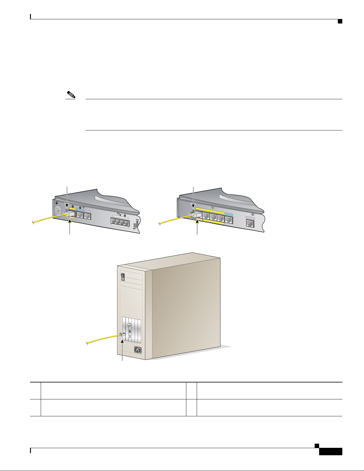
1: Connect the Router to a PC
Follow the steps shown in Figure 1 on page 3 to connect the router to a PC with an Ethernet network
interface card (NIC) installed. Figure 1 shows portions of two router back panels. Refer to the back panel
that is similar to the back panel of the router that you are installing.
Note Verify that the TO HUB/TO PC switch on the left side of the back panel has been set to the TO PC
position (out). If the button is in, press it to set it to the out position. You will know that the position is
correct if the LED for this port on the front of the router comes on after you have finished installing the
router and the PCs have been turned on.
To connect additional computers to Cisco 827H, Cisco 828, or SOHO 78 routers, obtain standard
Ethernet cables, and attach them to the router via Ethernet ports 1, 2, and 3.
Figure 1 Connecting the Router to a PC
1: Connect the Router to a PC
1. Set TO HUB/TO PC
button.
ETHERNET
TO HUB
TO PC
1
CONSOLE
Model Cisco 827-4V
ADSL
2. Connect yellow cable to
ETHERNET port on router.
Cisco 827, Cisco 827-4V,
or SOHO 77 router
PHONE
+5,+12,-12,-24,-71 VDC
4
3
2
1
PC
1. Set TO HUB/TO PC
button.
T
O
H
U
B
E
T
H
E
R
N
T
O
P
C
E
T
10B
A
S
E
T
4
3
2
1
2. Connect yellow cable to
ETHERNET port on router.
Cisco 827H, Cisco 828,
SOHO 77H, or
SOHO 78 router
Model Cisco 828
C
O
N
S
O
LE
G
.S
H
D
S
L
74083
3. Connect other end of cable
to server, PC, or workstation.
1 Set TO HUB/TO PC button for Cisco 827, 827-4V, or
SOHO 77 router.
2 Set TO HUB/TO PC button for Cisco 827H, 828,
SOHO 77H or SOHO 78 router.
Cisco 820 Series and SOHO Series Routers Cabling and Setup Quick Start Guide
78-13937-04
3 Connect yellow cable to Ethernet port on router.
4 Connect other end of cable to server, PC, or workstation.
3
Page 4

2: Connect the Router to a Hub (Optional)
See the “3: Connect a Digital Subscriber Line” section on page 5 to complete the next step.
2: Connect the Router to a Hub (Optional)
If you have PCs connected to a hub, follow the steps shown in Figure 2 on page 4 to connect the router
to a hub. Figure 2 shows portions of two router back panels. Refer to the back panel that is similar to the
back panel of the router that you are installing.
Figure 2 Connecting the Router to a Hub
1. Set TO HUB/TO PC
button.
E
T
H
E
R
TO
N
ET
H
U
B
T
O
P
C
1
C
O
N
S
O
LE
A
D
S
L
Model Cisco 827-4V
2. Connect yellow cable to
ETHERNET port on router.
Cisco 827, Cisco 827-4V,
or SOHO 77 router
P
H
O
N
E
+5,+
12,-12
,-24,-71
V
D
4
3
2
C
1
Cisco 1528 Micro Hub 10/100
1X
2X
ETH
ER
SPEED
100BaseTX
10BaseT BLINK
LED
1
SOLID
2
5
6
NET
3
4
7
8
5X 6X
7X
3. Connect other
end of cable
to hub.
1. Set TO HUB/TO PC
button.
TO
HUB
ETHERN
TO
PC
ET 10BASE T
4
3
2
2. Connect yellow cable to
ETHERNET port on router.
3X
4X
8X
M
DI M
DI-X
4. If applicable, check setting
of hub equivalent of router
TO HUB/TO PC button.
Cisco 827H, Cisco 828,
SOHO 77H, or
SOHO 78 router
Model Cisco 828
CONSOLE
1
G.SHDSL
74082
1 Set TO HUB/TO PC button for Cisco 827, 827-4V, or
4 Cisco 1528 Micro Hub 10/100
SOHO 77 router.
2 Set TO HUB/TO PC button for Cisco 827H, 828,
5 Connect other end of cable to hub.
SOHO 77H or SOHO 78 router.
3 Connect yellow cable to Ethernet port on router. 6 If applicable, check settings of hub equivalent of router
TO HUB/TO PC button.
Verify that the TO HUB/TO PC switch on the left side of the back panel has been set to the TO HUB
position (in). If the button is out, press it to set it to the in position. You will know that the position is
correct if the LED for this port on the front of the router lights after the router and the PCs have been
turned on.
Cisco 820 Series and SOHO Series Routers Cabling and Setup Quick Start Guide
4
78-13937-04
Page 5

Note You must use a crossover cable to connect a hub to an Ethernet port other than the ETHERNET 4 port
on Cisco 827H, Cisco 828, SOHO 77H or SOHO 78 routers. Crossover cables must be purchased
separately.
3: Connect a Digital Subscriber Line
Follow the steps in Figure 3 to connect an asymmetric digital subscriber line (ADSL) or G.SHDSL line
to the xDSL port on your router. Figure 3 shows back panels for ADSL and for G.SHDSL routers. Refer
to the back panel that is similar to the back panel of the router that you are installing.
Note The instructions in Figure 3 are for a straight-through ADSL cable, but they also apply if you are using
a crossover cable to connect your ADSL line. If you have microfilters or do not have the phone service
on the same line, use the lavender CAB-ADSL-RJ11 cable. If you have a splitter installed, use the
lavender CAB-ADSL-RJ11X cable with the blue stripe.
Figure 3 Connecting the Router to an xDSL Line
3: Connect a Digital Subscriber Line
Cisco 826, Cisco 827 series,
or SOHO 76 or 77 series router
Model Cisco 827 H
CONSOLE
1
ADSL
1. Connect lavender cable to
ADSL port on router.
TO HUB
TO PC
4
ETHERNET 10BASE T
3
Cisco 828 or
SOHO 78 router
Model Cisco 828
CONSOLE
2
1
G.SHDSL
1. Connect lavender cable to
G.SHDSL port on router.
TO HUB
TO PC
4
ETHERNET 10BASE T
3
2
2. Connect other end of cable
to wall jack.
74081
1 Cisco 828 or SOHO 78 router 4 Connect lavender cable to ADSL port on router.
2 Cisco 826, Cisco 827 series, or SOHO 76 or 77 series
5 Connect other end of cable to wall jack.
router
3 Connect lavender cable to G.SHDSL port on router. 6
78-13937-04
Cisco 820 Series and SOHO Series Routers Cabling and Setup Quick Start Guide
5
Page 6

4: Connect a Cisco 827-4V Router to a Phone or Fax
4: Connect a Cisco 827-4V Router to a Phone or Fax
If you have a Cisco 827-4V router, you can connect analog telephones or fax machines to your router.
Use the cables provided with these devices.
The gray PHONE 1, 2, 3, and 4 ports are RJ-11 connectors. If you are outside North America, you must
buy and attach adapters that allow telephones or faxes to be connected to the RJ-11 connectors. In some
countries, these adapters need additional electronics to convert the telephones or faxes to work properly
with the router phone ports. For example, in the United Kingdom, you must buy an adapter that also
provides a master socket, which causes incoming calls to ring the connected devices. For information on
recommended master sockets, see the Cisco 827 and SOHO 77 Routers Hardware Installation Guide.
Follow the steps in Figure 4 on page 6 to connect a telephone or a fax machine to a Cisco 827-4V router.
Caution Do not connect the router telephone ports to the telephone wall jack. These ports are not meant for direct
connection to the public network. This connection can damage your router.
Figure 4 Connecting a Telephone to a Cisco 827-4V Router
Cisco 827-4V router
ETHERNET
TO HUB
TO PC
1
CONSOLE
Model Cisco 827-4V
ADSL
PHONE
+5,+12,-12,-24,-71 VDC
4
3
2
1
1. Connect telephone cable to
gray PHONE port 1, 2, 3, or 4.
If you are connecting only one
device, use PHONE port 1.
Analog telephone
2. Connect other end of
cable to telephone or
fax machine.
1 Cisco 827-4V router 3 Analog telephone
2 Connect telephone cable to gray PHONE port 1, 2, 3, or
4 Connect other end of cable to telephone or fax machine.
4. If you are connecting only one devie, use
PHONE port 1.
65597
Cisco 820 Series and SOHO Series Routers Cabling and Setup Quick Start Guide
6
78-13937-04
Page 7

5: Connect the Power and Turn On the Router
5: Connect the Power and Turn On the Router
Follow the steps in Figure 5 on page 7 to connect an AC adapter to the Cisco router and turn it on.
(Figure 5 shows a Cisco 827-4V router, but the process applies to all Cisco 820-series and SOHO
routers.)
Caution Be sure to use the power supply that was supplied with your Cisco router. Power supplies for other Cisco
routers will not plug in to the power receptacle on the back panel.
After you turn on the router, the OK LED on the front will turn on. After a minute or two, the xDSL CD
LED will turn on. The Ethernet LEDs for the Ethernet ports to which you have connected PCs or hubs
will turn on a minute or two after you have turned on the PCs.
Figure 5 Connecting the Power to the Router
1. Press power switch to standby ( ).
Cisco 827-4V router
ETHERNET
TO HUB
TO PC
CONSOLE
1
Model Cisco 827-4V
ADSL
3
PHONE
2
14
+5,+12,-12,-24,-71 VDC
65594
5. Press power
switch to on ( ).
4. Connect power
cord to electrical
Desktop power
supply
2. Connect power
supply cable.
outlet.
3. Connect power cord
to power supply.
1 Press power switch to standby. 4 Desktop power supply
2 Cisco 827-4V router. 5 Connect power cord to electrical outlet.
3 Connect power supply cable. 6 Press power switch to on.
4 Connect power cord to power supply. 7
78-13937-04
Cisco 820 Series and SOHO Series Routers Cabling and Setup Quick Start Guide
7
Page 8

6: Check the PC Configuration
6: Check the PC Configuration
Each PC that is connected to the router must be configured to use the Transmission Control
Protocol/Internet Protocol (TCP/IP) and to obtain its IP address automatically. Follow these steps to
configure each PC that is running Microsoft Windows NT or Microsoft Windows 95 or 98. If the PC is
running a different version of Microsoft Windows, refer to the documentation that came with the PC.
Step 1 Start the PC, and open the Control Panel.
Step 2 Click the Network icon to display the Network window.
Step 3 Verify that TCP/IP has been added and associated with the Ethernet adapter. TCP/IP is shown as a cable
icon in the Configuration window on Microsoft Windows 95 and 98; and as a cable icon in the Protocol
window on Microsoft Windows NT. If the icon is not visible, click Add, and add Microsoft TCP/IP.
Step 4 To verify that the PC is configured to obtain an IP address automatically, click the TCP/IP cable icon,
and select the IP address tab in the TCP/IP Properties window. If it is unchecked, check Obtain an IP
address from a DHCP server. The IP address and Subnet mask fields should be grayed out.
Step 5 To accept all changes and exit this window, click OK. Then click OK in the Network window.
Step 6 If you are prompted, click Ye s to reboot the PC.
For more information on how to configure TCP/IP, refer to the Cisco Router Web Setup Troubleshooting
Guide, which is available on Cisco.com.
7: Configure the Router with Cisco Router Web Setup
The Cisco Router Web Setup (CRWS) software is loaded on the router and should be used to configure
it to connect to the Internet. The CRWS software runs on Netscape version 3.0 to 4.7, and on Internet
Explorer version 4.0 or later. Follow these steps to start the CRWS software and configure the router:
Step 1 Start, or restart, a PC connected to one of the router Ethernet ports (1, 2, 3, or 4).
Step 2 Open a web browser. Make sure that the browser is set to work in online mode.
• In Internet Explorer, click the File menu, and verify that the “work offline” option is unchecked.
• In Netscape, the default selection in the File menu is set to work online.
Step 3 Type in the following universal resource locator (URL):
http://10.10.10.1
The home page of the router should appear after one or two minutes.
Tip If the CRWS home page does not appear when you enter the URL http://10.10.10.1, test the connection
between the PC and the router by doing the following:
1. Check that the OK LED on the router is on, and check the cable connection between the router and
the PC. Be sure that the TO HUB/TO PC button is in the correct position. The position is correct if
the LED for the port on the front of the router is on.
2. If the CRWS home page still does not appear, verify that the web browser’s “work offline” option
is disabled.
Cisco 820 Series and SOHO Series Routers Cabling and Setup Quick Start Guide
8
78-13937-04
Page 9

8: Congratulations! You’re Done!
3. If the web page still does not appear, verify that the PC is configured to automatically receive an IP
address. Follow the instructions in Step 4 in section “6: Check the PC Configuration.” If you need
more information refer to the Cisco Router Web Setup Troubleshooting Guide, which is available on
Cisco.com.
4. If the PC is configured to automatically receive an IP address, but the web page still does not appear,
select Start/Run, type winipcfg in the Run window, and examine the address in the IP address field.
The address should be in the format 10.10.10.X, in which X is a number that is 2 or greater; for
example, 10.10.10.2 or 10.10.10.3. If the IP address is not in this format, verify that an Ethernet
adapter name is visible in the Adapter field. If it is not, return to Step 3 in section “6: Check the PC
Configuration,” add TCP to the list of protocols. Then return to section “7: Configure the Router
with Cisco Router Web Setup,” and complete the procedure.
Step 4 If you have no special configuration requirements, click the Router Setup link on the home page, and
then click Quick Setup. (This may appear as Easy Setup on some models.) Then, enter the user name
and password provided to you by your Internet service provider, and click Apply.
Step 5 If you need to configure special features such as Network Address Translation (NAT), click the
appropriate links on the home page, and complete the configuration screens.
Step 6 Click the Password link on the home page, and set a password for the router.
Step 7 Click the Tes t C on n e ct i o n link on the home page, and allow the connection to be tested.
Step 8 Select Start/Run, and type winipcfg in the Open field of the Run window. When the IP Config window
appears, click Release, and then click Renew to release and renew the PC’s IP address.
Alternatively, open a DOS window, and enter ipconfig /release to release the PC’s IP address.Then enter
ipconfig /renew to renew the IP address of the PC.
Step 9 Open a web browser on the PC, and connect to a website.
8: Congratulations! You’re Done!
If you were able to connect to a website, you have completed the cabling and setup of your router, and
you can continue to use it to access the Internet.
If you need to configure more features, click the CRWS link for the feature you need to configure, and
enter configuration values for the router.
Related Documentation
For more information, refer to the following publications:
• Cisco 827 and SOHO 77 Routers Hardware Installation Guide—Provides detailed cabling and
hardware information for the Cisco 827 and SOHO 77 routers.
• Cisco 827 Routers Software Configuration Guide—Provides detailed configuration instructions for
the Cisco 827 and SOHO 77 routers.
• Cisco 828 Router and SOHO 78 Router Hardware Installation Guide—Provides detailed cabling
and hardware information for the Cisco 828 and SOHO 78 routers.
78-13937-04
Cisco 820 Series and SOHO Series Routers Cabling and Setup Quick Start Guide
9
Page 10

Obtaining Documentation and Submitting a Service Request
• Cisco 828 Router and SOHO 78 Router Software Configuration Guide—Provides detailed
configuration instructions for the Cisco 828 and SOHO 78 routers.
• Cisco Router Web Setup Troubleshooting Guide—Provides basic router configuration information.
• Configuration Note for the Cisco SOHO 77 Router—Provides software configuration information
for the SOHO 77 and 77H routers.
These documents are available on the World Wide Web. You can access the most current Cisco documentation
on the World Wide Web at the following sites:
• http://www.cisco.com
• http://www-china.cisco.com
• http://www-europe.cisco.com
Obtaining Documentation and Submitting a Service Request
For information on obtaining documentation, submitting a service request, and gathering additional
information, see the monthly What’s New in Cisco Product Documentation, which also lists all new and
revised Cisco technical documentation, at:
http://www.cisco.com/en/US/docs/general/whatsnew/whatsnew.html
Subscribe to the What’s New in Cisco Product Documentation as a Really Simple Syndication (RSS) feed
and set content to be delivered directly to your desktop using a reader application. The RSS feeds are a free
service and Cisco currently supports RSS Version 2.0.
10
Cisco 820 Series and SOHO Series Routers Cabling and Setup Quick Start Guide
78-13937-04
 Loading...