

Page 1

Quick Start Guide
Cisco 815 Integrated Services Router Cabling and Installation Quick
Start Guide
INCLUDING LICENSE AND WARRANTY
1 Cisco 90-Day Limited Hardware Warranty Terms
2 Overview
3 Documents, Equipment, and Tools
4 Ports and LEDs
5 Install the Router
6 Connect to the Router
7 Interface Numbering
8 Power Up the Router
9 Perform Initial Configuration
10 Where to Go Next
11 Obtaining Documentation
12 Documentation Feedback
13 Cisco Product Security Overview
14 Obtaining Technical Assistance
15 Obtaining Additional Publications and Information
Page 2

Revised November 2007, 78-17436-03
1 Cisco 90-Day Limited Hardware Warranty Terms
There are special terms applicable to your hardware warranty and various services that you can use during the warranty period.
Your formal Warranty Statement, including the warranties and license agreements applicable to Cisco software, is available on
Cisco.com. Follow these steps to access and download the Cisco Information Packet and your warranty and license agreements
from Cisco.com.
1. Launch your browser, and go to this URL:
http://www.cisco.com/univercd/cc/td/doc/es_inpck/cetrans.htm
The Warranties and License Agreements page appears.
2. To read the Cisco Information Packet, follow these steps:
a. Click the Information Packet Number field, and make sure that the part number 78-5235-03A0 is highlighted.
b. Select the language in which you would like to read the document.
c. Click Go.
The Cisco Limited Warranty and Software License page from the Information Packet appears.
d. Read the document online, or click the PDF icon to download and print the document in Adobe Portable Document
Format (PDF).
Note You must have Adobe Acrobat Reader to view and print PDF files. You can download the reader from Adobe’s
website, http://www.adobe.com.
3. To read translated and localized warranty information about your product, follow these steps:
a. Enter this part number in the Warranty Document Number field:
78-5236-01C0
b. Select the language in which you would like to read the document.
c. Click Go.
The Cisco warranty page appears.
d. Review the document online, or click the PDF icon to download and print the document in Adobe Portable Document
Format (PDF).
You can also contact the Cisco service and support website for assistance:
http://www.cisco.com/public/Support_root.shtml
Duration of Hardware Warranty
Ninety (90) days.
Replacement, Repair, or Refund Policy for Hardware
Cisco or its service center will use commercially reasonable efforts to ship a replacement part within ten (10) working days after
receipt of a Return Materials Authorization (RMA) request. Actual delivery times can vary, depending on the customer location.
Cisco reserves the right to refund the purchase price as its exclusive warranty remedy.
2
Page 3

To Receive a Return Materials Authorization (RMA) Number
Contact the company from whom you purchased the product. If you purchased the product directly from Cisco, contact your
Cisco Sales and Service Representative.
Complete the information below, and keep it for reference:
Company product purchased from
Company telephone number
Product model number
Product serial number
Maintenance contract number
Product Serial Number Location
You may need your product serial number when calling the Technical Assistance Center (TAC).
The serial number label for the Cisco 815 integrated services router is located on the back of the chassis, to the right of the
power switch.
Cisco Product Identification Tool
The Cisco Product Identification (CPI) tool provides detailed illustrations and descriptions showing where to find serial number
labels on Cisco products. It includes the following features:
• A search option that allows browsing for models using a tree-structured product hierarchy
• A search field on the final results page making it easier to look up multiple products
• Clear identification of end-of-sale products in results lists
The tool streamlines the process of locating serial number labels and identifying products. Serial number information expedites
the entitlement process and is important for access to support services.
The Cisco Product Identification tool can be accessed at the following URL:
http://tools.cisco.com/Support/CPI/index.do
Cisco Product Accessibility
This product family leverages a command line interface (CLI). The CLI is 508 conformant since it is text based and relies on a
keyboard for navigation. All functions of the router can be configured and monitored through the CLI.
For a complete list of guidelines and Cisco products adherence to accessibility, see Cisco Accessibility Products at the following
URL:
http://www.cisco.com/web/about/responsibility/accessibility/products
2 Overview
The Cisco 815 integrated services router (see Figure 1) is a small, modular desktop router that provides an integrated cable
solution. The Cisco 815 integrated services router communicates over a cable hybrid fiber coaxial (HFC) network for
office-to-Internet connectivity or branch-to-branch connectivity. The Cisco cable modem High-Performance WAN interface
cards (HWICs) are installed in the router as a fixed configuration for one HWIC full-feature cable modem high-speed
interaction, including quality of service (QoS) functionality.
3
Page 4
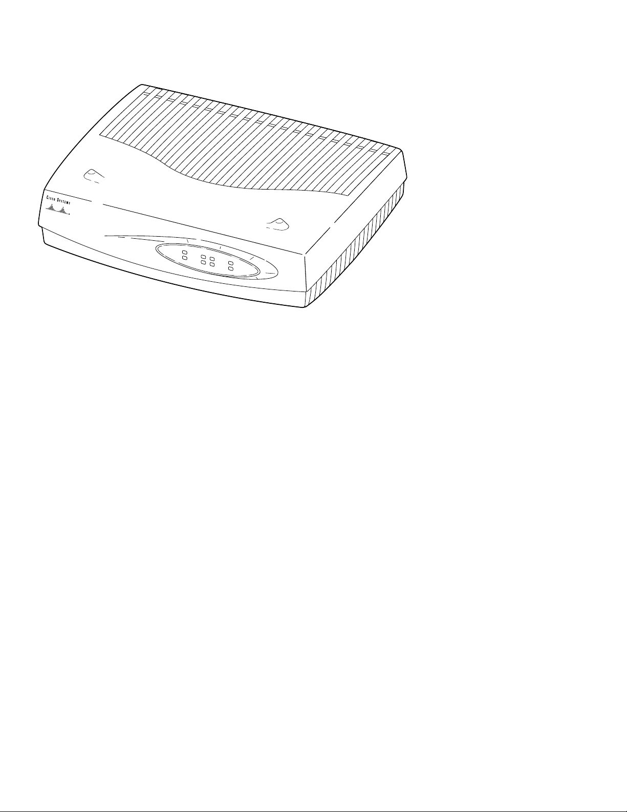
Figure 1 Cisco 815 Integrated Services Router
PWR
W
IC
0
ACT/CH0
W
IC1
ACT/CH0
ETH
OK
ACT
AC
T/CH1
ACT/CH1
CO
L
Cisco
800
series
router
146794
Hardware Features
The Cisco 815 integrated services router has the following hardware features:
• One cable modem Data-Over-Cable Service Interface Specification (DOCSIS) port
• One 10/100 Fast Ethernet port
• Four 10/100BASE-TX Ethernet switch ports
• 32 MB of flash memory and 64 MB of DRAM (DRAM can be upgraded to 128 MB)
• 32 MB of NVRAM
Software Features
The Cisco 815 integrated services router has the following software features:
• Cisco IOS IP Base software image
• Cisco IOS advanced security software image available as a factory upgrade option
• Supports virtual private network (VPN) when upgraded
• Supports a maximum of 16 VLANs
• Supports DOCSIS 2.0, DOCSIS 1.1, and DOCSIS 1.0
4
Page 5
3 Documents, Equipment, and Tools
This section describes the documents, equipment, and tools included with the Cisco 815 integrated services router.
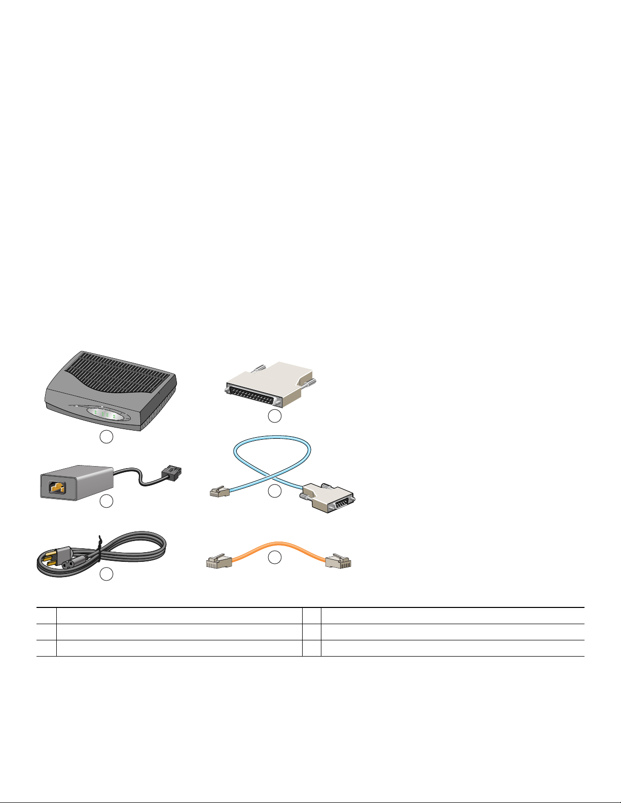
Items Included with the Cisco 815 Integrated Services Router
When you unpack the box containing your Cisco 815 integrated services router, you should find the following items:
• Power supply
• One DB-9-to-DB-25 modem adapter
• Power cable
• One RJ-45-to-DB-9 console cable
• One Ethernet cable
• Cisco.com card; Cisco product registration card
• Rubber chassis feet for desktop application
• Cisco Router and Security Device Manager CD
• Regulatory Compliance and Safety Information for the Cisco 800 Series and SOHO Series Routers document
• Cisco 815 Integrated Services Router Cabling and Installation Quick Start Guide (this document)
Figure 2 Items Included with the Cisco 815 Integrated Services Router
PWR
W
IC0
ACT/CH0
WIC1
ACT/CH1
ETH
ACT
OK
ACT/CH0
ACT/CH1
COL
4
1
5
2
6
3
1
Cisco 815 integrated services router
2
Power supply
3
Power cable
4
DB-9 to DB-25 adapter
5
Console cable (RJ-45 to DB-9)
6
Ethernet cable
146792
5
Page 6

Items Not Included with the Cisco 815 Integrated Services Router
One or more items in this list may be required for your installation:
• PC running terminal emulation software, or a modem for remote administrative access
• Cable for cable-modem interface
• Cable ties
• Number-2 Phillips screwdriver
User Documentation
For complete platform documentation, see the following URL:
http://www.cisco.com/en/US/products/hw/routers/ps380/tsd_products_support_series_home.html
All the documents referenced in this quick start guide are available on Cisco.com. For information on accessing Cisco.com, see
the “Where to Go Next” section on page 22. To view or print an online document in its original page format, click the PDF icon.
Translated Versions
http://www.cisco.com/en/US/products/hw/routers/ps380/tsd_products_support_series_home.html
http://www.cisco.com/en/US/products/hw/routers/ps380/tsd_products_support_series_home.html
4 Ports and LEDs
This section describes the ports and LEDs on the Cisco 815 integrated services router.
Back Panel Ports and LEDs
This section describes the router back panel ports and LEDs. See Figure 3, Table 1, and Table 2.
Figure 3 Back Panel
1
Cisco 815
WIC
4ESW
2
ACT LNK
2x
3x
4xACT
ACT LNK
ACT LNK
LNK
1x
FDX LINK100WIC 0 OK WIC 1 OKMOD OK
10/100 ETHERNET
3
CONSOLE
AUX
HWIC-CABLE-D-2
CABLE
4
DS
LINK
US
POWER
ONLINE
5
+5, +12, -12 VDC
146791
12
11
1
Kensington-compatible locking socket
2
WIC 0 slot
3
Console port
6
10
8
9
7
7
WIC 1 OK
8
MOD OK LED
9
Auxiliary port
6
Page 7
4
WIC 1 slot
5
Power switch
6
Power socket
10
10/100-Mbps Fast Ethernet port
11
FDX, 100, and LINK LEDs
12
WIC 0 OK LED
Table 1 Back Panel Connectors
Connector/Slot Label/Color Description
Fast Ethernet port 10/100 ETHERNET (yellow) Connects the router to the local Ethernet network through this
port. This port autosenses the speed (10 Mbps or 100 Mbps) and
duplex mode (full- or half-) of the device to which it is connected
and then operates at the same speed and duplex mode.
Auxiliary port AUX (black) Connects to a modem for remote configuration with Cisco IOS
software.
Console port CONSOLE (blue) Connects to a terminal or PC for local configuration using
Cisco IOS software.
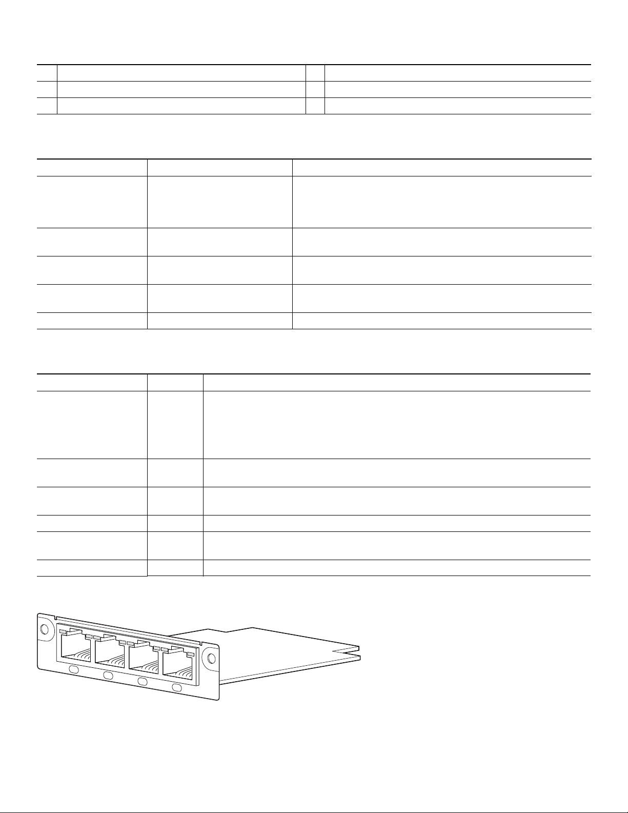
WIC-4ESW No label Supports interface card with four 10/100-BASE-TX Ethernet switch
ports. See Figure 4.
HWIC-CABLE-D-2 No label Supports one Cisco cable WIC. See Figure 5.
Table 2 Back Panel LEDs
LED Label Color Description
WIC0 OK Green On when the WIC is correctly installed in the card slot.
Two LEDS are associated with the WIC-4ESW: the right LED labeled LNK and the left
LED labeled ACT. The LNK (physical layer link) LED is on when the Cisco IOS software
recognizes the switch and the connection is up. The ACT (activity) LED indicates that
data is being transmitted or received on the slot.
FDX Green On solid—Ethernet port is operating in full-duplex mode.
Off—Ethernet port is operating in half-duplex mode.
100 Green On solid—Ethernet port is operating at 100 Mbps.
Off—Ethernet port is operating at 10 Mbps.
LINK Green On when the Ethernet link is up.
MOD OK Green On when the VPN hardware encryption module is installed and recognized by the Cisco
IOS software.
WIC1 OK Green On when the WIC is correctly installed in the card slot.
Figure 4 WIC-4ESW
WIC
4ESW
ACT
4x
LNK
ACT
3x
LNK
ACT
2x
LNK
ACT
1x
LNK
95777
7
Page 8
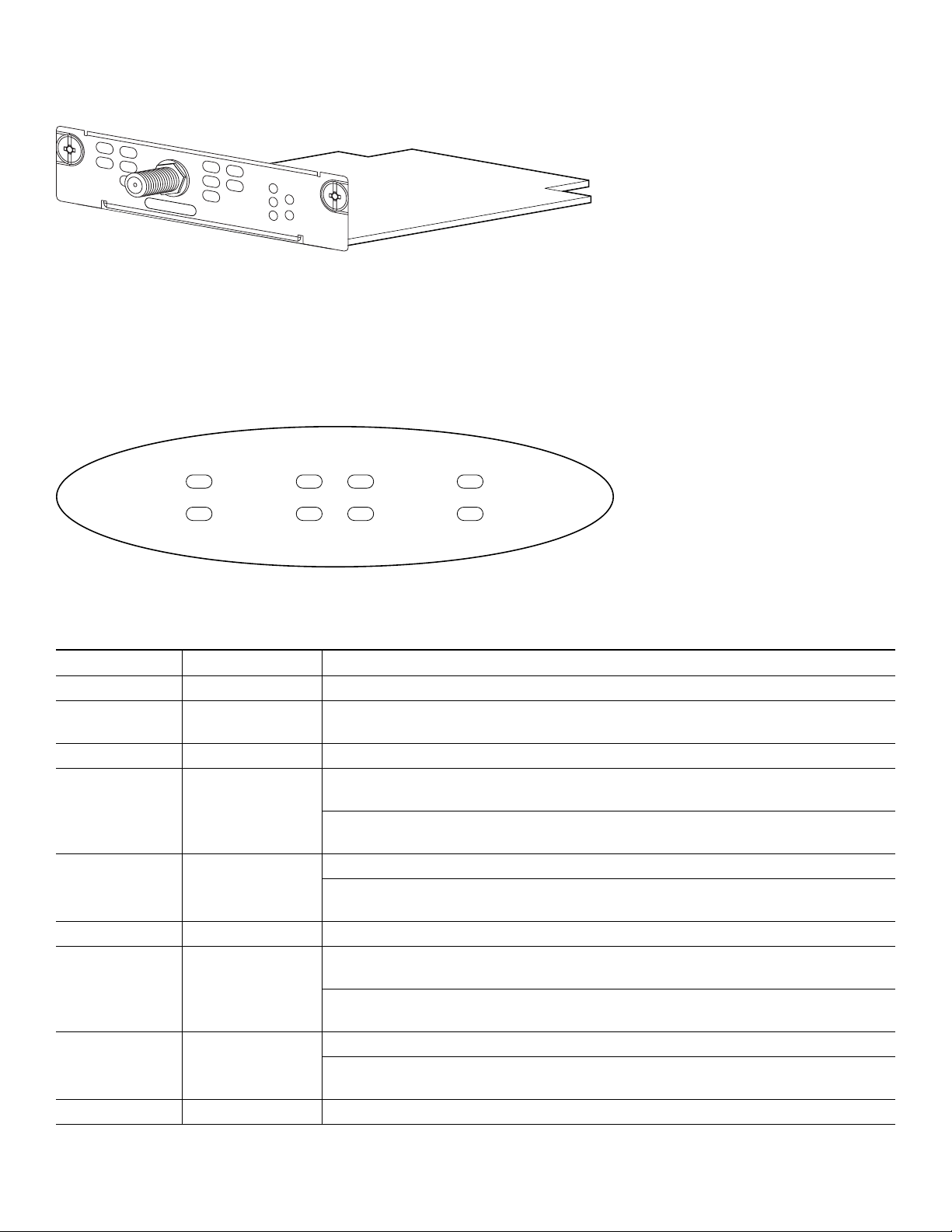
Figure 5 HWIC-CABLE-D-2
HWIC-CABLE-D-2
CABLE
DS
US
ONLINE
LINK
POWER
146788
Front Panel LEDs
Use the router front panel LEDs to determine network activity and status on the Ethernet WIC ports. See Figure 6 and Table 3.
Figure 6 Front Panel LEDs
PWR
OK
Table 3 Front Panel LEDs
WIC0
ACT/CH0
ACT/CH1
WIC1
ACT/CH0
ACT/CH1
ETH
ACT
COL
65537
LED Label Color Description
PWR Green On when DC power is being supplied to the router.
OK Green Blinks during the power-on self-test (POST). On when the router has successfully
booted up and the software is functional.
WIC0
ACT/CH0 Green Blinks when data is being sent to or received from the port on the card in the WIC0
slot.
2-port serial cards—Blinks when data is being sent to or received from the first port
on the 2-port card in the WIC0 slot.
ACT/CH1 Green Remains off.
2-port serial cards—Blinks when data is being sent to or received from the second port
on the 2-port card in the WIC0 slot.
WIC1
ACT/CH0 Green Blinks when data is being sent to or received from the port on the card in the WIC1
slot.
2-port serial cards—Blinks when data is being sent to or received from the first port
on the 2-port card in the WIC1 slot.
ACT/CH1 Green Remains off.
2-port serial cards—Blinks when data is being sent to or received from the second port
on the 2-port card in the WIC1 slot.
ETH N/A N/A
8
Page 9

Table 3 Front Panel LEDs (continued)
LED Label Color Description
ACT Green Blinks when there is network activity on the Ethernet port.
COL Yellow Blinks when there are packet collisions on the local Ethernet network.
5 Install the Router
Set the Cisco 815 integrated services router on a desktop or table. Attach the four rubber feet to the bottom of the chassis. For
more detailed installation instructions, see the Cisco 815 integrated services router hardware installation documentation at the
following URL:
http://www.cisco.com/en/US/products/hw/routers/ps380/prod_installation_guides_list.html
Safety Information
For safety information you must know before working on your Cisco router, see the Regulatory Compliance and Safety
Information for the Cisco 800 Series and SOHO Series Routers document.
The Regulatory Compliance and Safety Information for the Cisco 800 Series and SOHO Series Routers document contains
translations of the warnings that appear in this quick start guide.
9
Page 10

Warnings and Cautions
When you install the Cisco 815 integrated services router, observe the warnings and precautions in this section.
In addition, for safety information you must know before working on your Cisco router, see the Regulatory Compliance and
Safety Information for Cisco 800 Series and SOHO Series Routers document that accompanied this device. The Regulatory
Compliance and Safety Information document also contains translations of the warnings that appear in this quick start guide.
Statement 1071—Warning Definition
Warning
Waarschuwing
Varoitus
IMPORTANT SAFETY INSTRUCTIONS
This warning symbol means danger. You are in a situation that could cause bodily injury. Before you
work on any equipment, be aware of the hazards involved with electrical circuitry and be familiar
with standard practices for preventing accidents. Use the statement number provided at the end of
each warning to locate its translation in the translated safety warnings that accompanied this
device.
SAVE THESE INSTRUCTIONS
BELANGRIJKE VEILIGHEIDSINSTRUCTIES
Dit waarschuwingssymbool betekent gevaar. U verkeert in een situatie die lichamelijk letsel kan
veroorzaken. Voordat u aan enige apparatuur gaat werken, dient u zich bewust te zijn van de bij
elektrische schakelingen betrokken risico's en dient u op de hoogte te zijn van de standaard
praktijken om ongelukken te voorkomen. Gebruik het nummer van de verklaring onderaan de
waarschuwing als u een vertaling van de waarschuwing die bij het apparaat wordt geleverd, wilt
raadplegen.
BEWAAR DEZE INSTRUCTIES
TÄRKEITÄ TURVALLISUUSOHJEITA
Tämä varoitusmerkki merkitsee vaaraa. Tilanne voi aiheuttaa ruumiillisia vammoja. Ennen kuin
käsittelet laitteistoa, huomioi sähköpiirien käsittelemiseen liittyvät riskit ja tutustu
onnettomuuksien yleisiin ehkäisytapoihin. Turvallisuusvaroitusten käännökset löytyvät laitteen
mukana toimitettujen käännettyjen turvallisuusvaroitusten joukosta varoitusten lopussa näkyvien
lausuntonumeroiden avulla.
Statement 1071
10
Attention
SÄILYTÄ NÄMÄ OHJEET
IMPORTANTES INFORMATIONS DE SÉCURITÉ
Ce symbole d'avertissement indique un danger. Vous vous trouvez dans une situation pouvant
entraîner des blessures ou des dommages corporels. Avant de travailler sur un équipement, soyez
conscient des dangers liés aux circuits électriques et familiarisez-vous avec les procédures
couramment utilisées pour éviter les accidents. Pour prendre connaissance des traductions des
avertissements figurant dans les consignes de sécurité traduites qui accompagnent cet appareil,
référez-vous au numéro de l'instruction situé à la fin de chaque avertissement.
CONSERVEZ CES INFORMATIONS
Page 11

Warnung
Avvertenza
Advarsel
WICHTIGE SICHERHEITSHINWEISE
Dieses Warnsymbol bedeutet Gefahr. Sie befinden sich in einer Situation, die zu Verletzungen führen
kann. Machen Sie sich vor der Arbeit mit Geräten mit den Gefahren elektrischer Schaltungen und
den üblichen Verfahren zur Vorbeugung vor Unfällen vertraut. Suchen Sie mit der am Ende jeder
Warnung angegebenen Anweisungsnummer nach der jeweiligen Übersetzung in den übersetzten
Sicherheitshinweisen, die zusammen mit diesem Gerät ausgeliefert wurden.
BEWAHREN SIE DIESE HINWEISE GUT AUF.
IMPORTANTI ISTRUZIONI SULLA SICUREZZA
Questo simbolo di avvertenza indica un pericolo. La situazione potrebbe causare infortuni alle
persone. Prima di intervenire su qualsiasi apparecchiatura, occorre essere al corrente dei pericoli
relativi ai circuiti elettrici e conoscere le procedure standard per la prevenzione di incidenti.
Utilizzare il numero di istruzione presente alla fine di ciascuna avvertenza per individuare le
traduzioni delle avvertenze riportate in questo documento.
CONSERVARE QUESTE ISTRUZIONI
VIKTIGE SIKKERHETSINSTRUKSJONER
Dette advarselssymbolet betyr fare. Du er i en situasjon som kan føre til skade på person. Før du
begynner å arbeide med noe av utstyret, må du være oppmerksom på farene forbundet med
elektriske kretser, og kjenne til standardprosedyrer for å forhindre ulykker. Bruk nummeret i slutten
av hver advarsel for å finne oversettelsen i de oversatte sikkerhetsadvarslene som fulgte med denne
enheten.
Aviso
¡Advertencia!
Varning!
TA VARE PÅ DISSE INSTRUKSJONENE
INSTRUÇÕES IMPORTANTES DE SEGURANÇA
Este símbolo de aviso significa perigo. Você está em uma situação que poderá ser causadora de
lesões corporais. Antes de iniciar a utilização de qualquer equipamento, tenha conhecimento dos
perigos envolvidos no manuseio de circuitos elétricos e familiarize-se com as práticas habituais de
prevenção de acidentes. Utilize o número da instrução fornecido ao final de cada aviso para
localizar sua tradução nos avisos de segurança traduzidos que acompanham este dispositivo.
GUARDE ESTAS INSTRUÇÕES
INSTRUCCIONES IMPORTANTES DE SEGURIDAD
Este símbolo de aviso indica peligro. Existe riesgo para su integridad física. Antes de manipular
cualquier equipo, considere los riesgos de la corriente eléctrica y familiarícese con los
procedimientos estándar de prevención de accidentes. Al final de cada advertencia encontrará el
número que le ayudará a encontrar el texto traducido en el apartado de traducciones que acompaña
a este dispositivo.
GUARDE ESTAS INSTRUCCIONES
VIKTIGA SÄKERHETSANVISNINGAR
Denna varningssignal signalerar fara. Du befinner dig i en situation som kan leda till personskada.
Innan du utför arbete på någon utrustning måste du vara medveten om farorna med elkretsar och
känna till vanliga förfaranden för att förebygga olyckor. Använd det nummer som finns i slutet av
varje varning för att hitta dess översättning i de översatta säkerhetsvarningar som medföljer denna
anordning.
SPARA DESSA ANVISNINGAR
11
Page 12

13
12
Page 13

Aviso
INSTRUÇÕES IMPORTANTES DE SEGURANÇA
Este símbolo de aviso significa perigo. Você se encontra em uma situação em que há risco de lesões
corporais. Antes de trabalhar com qualquer equipamento, esteja ciente dos riscos que envolvem os
circuitos elétricos e familiarize-se com as práticas padrão de prevenção de acidentes. Use o
número da declaração fornecido ao final de cada aviso para localizar sua tradução nos avisos de
segurança traduzidos que acompanham o dispositivo.
GUARDE ESTAS INSTRUÇÕES
Advarsel
VIGTIGE SIKKERHEDSANVISNINGER
Dette advarselssymbol betyder fare. Du befinder dig i en situation med risiko for
legemesbeskadigelse. Før du begynder arbejde på udstyr, skal du være opmærksom på de
involverede risici, der er ved elektriske kredsløb, og du skal sætte dig ind i standardprocedurer til
undgåelse af ulykker. Brug erklæringsnummeret efter hver advarsel for at finde oversættelsen i de
oversatte advarsler, der fulgte med denne enhed.
GEM DISSE ANVISNINGER
Page 14

15
14
Page 15

Warning
Before working on a system that has an on/off switch, turn OFF the power and unplug the power cord.
Statement 1
Warning
Warning
Caution To prevent damage to the chassis, never attempt to lift of tilt the chassis by the plastic panel on the front. Always
Caution To prevent damage to the chassis, never attempt to lift or tilt the chassis by the plastic panel on the front. Always
Caution Your chassis installation must allow unrestricted airflow for chassis cooling. For placing the router on a desktop,
Caution Do not place any items that weigh more than 10 pounds (4.5 kilograms) on top of the chassis, and do not stack
Ultimate disposal of this product should be handled according to all national laws and regulations.
To prevent the system from overheating, do not operate it in an area that exceeds the maximum recommended
ambient temperature of 40 deg.
hold the chassis by the metal body.
hold the chassis by the metal body.
keep at least 1 inch (2.54 cm) of clear space beside the cooling inlet and exhaust vents.
routers on a desktop.
Statement 1047
Statement 1040
Caution There are no field-replaceable parts inside the router. Do not open the router enclosure to replace parts.
6 Connect to the Router
This section describes the procedures for cable connections.
Page 16

Warning
Warning
Note The installation must comply with all required electrical codes applicable at the installation site.
Do not work on the system or connect or disconnect cables during periods of lightning activity.
Read the installation instructions before connecting the system to the power source.
Statement 1004
Statement 1001
Cable Connections
Warning
Note One or two Ethernet cables are typically provided with the Cisco 815 integrated services router. Additional cables and
Connecting the Router Console Port to a Terminal or PC
Hazardous network voltages are present in WAN ports regardless of whether power to the router is OFF or ON. To
avoid electric shock, use caution when working near WAN ports. When detaching cables, detach the end away
from the router first.
transceivers can be ordered from Cisco. For ordering information, contact customer service. For cable pinouts, see the
Cisco Modular Access Router Cable Specifications document.
Statement 1026
Follow these steps to connect the router to a terminal or PC:
Step 1 This step is required only if you want to use the Cisco IOS CLI to configure or troubleshoot the router. To use the
Cisco IOS software, you must connect the router to a terminal or to a PC with terminal emulation software. Terminal
emulation software should be configured with the following settings:
• 9600 bps
• 8data bits
• No parity bits
• 1 stop bit
Step 2 Connect the RJ-45 end of the console cable to the CONSOLE port on the back panel of the router, as shown in Figure 7.
16
Page 17

Figure 7 Connecting the Console Cable to the Router
WIC
4ESW
4x
Cisco 815
WIC0OK
3x
ACT LNK ACT LNK ACT LNK
2x
ACT LNK
1x
FDX
100
LINK
10/100 ETHERNET
CONSOLE
AUX
HWIC-CABLE-D-2
D
S
US
CABLE
MODOK
O
NL
INE
WIC1OK
LINK
POW
E
R
+5, +12, -12 VDC
4
1
2
3
146793
1
Console cable
2
Console port
3
To PC or terminal
4
Cisco 815 integrated services router
Step 3 Connect the DB-9 end of the console cable to the serial port on your PC. If this connection does not fit your PC serial
port, you must provide an adapter.
7 Interface Numbering
Table 4 summarizes interface numbering on a Cisco 815 integrated services router.
Table 4 Interface Numbering on Cisco 815 Integrated Services Router
Slot/Connector Slot Type Interface Numbering Notation
0 Cable modem (WIC 1) c0
1 10/100 FastEthernet (built-in) fa0
2 FastEthernet (WIC-4ESW in WIC 0) fa1
fa2
fa3
fa4
17
Page 18

8 Power Up the Router
This section provides the procedures for powering up your Cisco 815 integrated services router.
Caution To ensure adequate cooling, never operate the router unless the cover and all WICs and cover plates are installed.
Checklist for Power-Up
You are ready to power up the Cisco 815 integrated services router after the following steps are completed:
• Chassis is securely mounted and grounded. (See the “Install the Router” section on page 9.)
• Power and interface cables are connected. (See the “Connect to the Router” section on page 15.)
• PC with terminal emulation program is connected to the console port, powered up, and configured for 9600 bps, 8 data
bits, 1 stop bit, no flow control, and no parity.
• Suitable PC COM port is selected in the terminal emulation program.
Note For initial power-up, a direct console connection is recommended. After the initial configuration is completed, a remote
modem connection can be used for router management.
Powering Up the Router
Follow these steps to power up your Cisco 815 integrated services router and to verify that it goes through its initialization and
self-test. After the router completes the self-test, it is ready to be configured.
Note Use the back panel LEDs during router installation to confirm that you have correctly connected all the cables to the
router.
Note To view the boot sequence, you must have a console connection to the Cisco 815 integrated services router before it
powers up.
Step 1 Make sure that your PC is powered up and connected as described in the “Checklist for Power-Up” section.
Step 2 Move the power switch to the ON position. The SYS PWR LED on the front of the chassis blinks green. The fans
operate once the router reaches a threshold point temperature. If this does not happen, see the Troubleshooting module
in the online Cisco 815 integrated services router hardware installation documentation at the following URL:
http://www.cisco.com/en/US/products/hw/routers/ps380/prod_installation_guides_list.html
Startup messages appear in your terminal emulation program window. When the startup messages end, the SYS PWR
LED shows solid green.
Caution Do not press any keys on the keyboard until the messages stop and the SYS PWR LED is solid green. Any keys
pressed during this time are interpreted as the first command typed when the messages stop, which might cause the
router to power off and restart. It takes a few minutes for the messages to stop.
If you see the following messages, the router has booted with a configuration file and is ready for initial configuration
using Cisco Router and Security Device Manager (Cisco SDM):
yourname con0 is now available
Press RETURN to get started.
18
Page 19

Note Because Cisco SDM is installed on your router by default, we recommend using Cisco SDM to perform the
initial configuration.
See the “Configure the Router Using Cisco Router and Security Device Manager” section on page 19 to learn how to
configure your router using Cisco SDM, or how to obtain Cisco SDM and install it on your router.
Note If you do not have Cisco SDM on your router, and would like to use Cisco SDM, go to the following location
for instructions on how to install it on your Cisco 815 series router:
http://www.cisco.com/go/sdm
If you see the following messages, the router has booted and is ready for initial configuration using the setup command
facility or the command-line interface (CLI):
--- System Configuration Dialog ---
At any point you may enter a question mark '?' for help.
Use ctrl-c to abort configuration dialog at any prompt.
Default settings are in square brackets '[]'.
Would you like to enter the initial configuration dialog? [yes/no]:
To use the setup command facility and use the CLI to configure the router, see the “Setting Up the Initial
Configuration Using the Setup Command Facility” and “Setting Up the Initial Configuration Using the Setup
Command Facility” sections.
If the rommon 1> prompt appears, your system has booted in ROM monitor mode.
Verifying the Hardware Configuration
To display and verify the hardware features, enter the show version command. This command displays the system hardware
version; the installed software version; the names and sources of configuration files; the boot images; and the amount of installed
DRAM, NVRAM, and flash memory.
9 Perform Initial Configuration
This section provides the procedures for performing the initial configuration of your Cisco 815 integrated services router.
Configure the Router Using Cisco Router and Security Device Manager
Cisco Router and Security Device Manager (Cisco SDM) is a web-based configuration tool that allows you to configure LAN
and WAN interfaces, routing, Network Address Translation (NAT), firewalls, VPNs, and other features on your router. If Cisco
SDM is installed on your router, configure the router by following the instructions in the Cisco Router and Security Device
Manager Quick Start Guide. If this document was not shipped with your router, you can obtain Cisco SDM and instructions
for installing it on your router from the following location:
http://www.cisco.com/go/sdm
Note To obtain the Cisco SDM release notes, and other Cisco SDM documentation, go to http://www.cisco.com/go/sdm and
click the Technical Documentation link.
19
Page 20

Setting Up the Initial Configuration Using the Setup Command Facility
This section shows how to use the setup command facility to configure a hostname for the Cisco 815 integrated services router,
to set passwords, and to configure an interface for communication with the management network. If the following messages
appear at the end of the startup sequence, the setup command facility has been invoked automatically:
--- System Configuration Dialog ---
At any point you may enter a question mark '?' for help.
Use ctrl-c to abort configuration dialog at any prompt.
Default settings are in square brackets '[]'.
Would you like to enter the initial configuration dialog? [yes/no]:
The setup command facility prompts you for basic information about your Cisco 815 integrated services router and network,
and it creates an initial configuration file. After the configuration file is created, you can use the CLI or Cisco Router and
Security Device Manager (Cisco SDM) to perform additional configuration.
The prompts in the setup command facility vary with the installed interface modules and the software image. The following
example and the user entries (in
For help with interface and port numbering, see the “Interface Numbering” section on page 17.
Note If you make a mistake while using the setup command facility, you can exit and run the setup command facility again.
Press Ctrl-C, and type setup at the privileged EXEC mode prompt (Router#).
bold) are shown as examples only.
Step 1 To proceed using the setup command facility, enter yes when the power-up messages have ended.
Would you like to enter the initial configuration dialog? [yes/no]: yes
Note If these messages do not appear, Cisco SDM and a default configuration file were installed on the router at the
factory. To use Cisco SDM to configure the router, see the “Configure the Router Using Cisco Router and
Security Device Manager” section on page 19.
Step 2 When the following messages appear, press Return to enter basic management setup:
At any point you may enter a question mark '?' for help.
Use ctrl-c to abort configuration dialog at any prompt.
Default settings are in square brackets '[]'.
Basic management setup configures only enough connectivity
for management of the system, extended setup will ask you
to configure each interface on the system
Would you like to enter basic management setup? [yes/no]: yes
Step 3 Enter a hostname for the Cisco 815 integrated services router (this example uses Router):
Configuring global parameters:
Enter host name [Router]: Router
Step 4 Enter an enable secret password. This password is encrypted (more secure) and cannot be seen when you view the
configuration:
The enable secret is a password used to protect access to
privileged EXEC and configuration modes. This password, after
entered, becomes encrypted in the configuration.
Enter enable secret: xxxxxx
Step 5 Enter an enable password that is different from the enable secret password. This password is not encrypted (less secure)
and can be seen when you view the configuration:
The enable password is used when you do not specify an
20
Page 21

enable secret password, with some older software versions, and
some boot images.
Enter enable password: xxxxxx
Step 6 Enter the virtual terminal password, which prevents unauthenticated access to the Cisco 815 integrated services router
through ports other than the console port:
The virtual terminal password is used to protect
access to the router over a network interface.
Enter virtual terminal password: xxxxxx
Step 7 Respond to the following prompts as appropriate for your network:
Configure SNMP Network Management? [yes]:
Community string [public]:
A summary of the available interfaces appears:
Current interface summary
Controller Timeslots D-Channel Configurable modes Status
Any interface listed with OK? value "NO" does not have a valid configuration
Interface IP-Address OK? Method Status Protocol
Step 8 Choose one of the available interfaces to connect the Cisco 815 integrated services router to the management network:
Enter interface name used to connect to the
management network from the above interface summary: 0/0
Step 9 Respond to the following prompts as appropriate for your network:
Configuring interface FastEthernet0/0:
Use the 100 Base-TX (RJ-45) connector? [yes]: yes
Operate in full-duplex mode? [no]: no
Configure IP on this interface? [yes]: yes
IP address for this interface: 172.1.2.3
Subnet mask for this interface [255.255.0.0] : 255.255.0.0
Class B network is 172.1.0.0, 16 subnet bits; mask is /16
Step 10 The configuration is displayed:
The following configuration command script was created:
hostname Router
enable secret 5 $1$D5P6$PYx41/lQIASK.HcSbfO5q1
enable password xxxxxx
line vty 0 4
password xxxxxx
snmp-server community public
!
no ip routing
!
interface Ethernet1/0
no shutdown
media-type 100BaseX
half-duplex
ip address 172.1.2.3 255.255.0.0
!
interface Ethernet1/1
shutdown
no ip address
!
end
Step 11 Respond to the following prompts. Choose [2] to save the initial configuration:
[0] Go to the IOS command prompt without saving this config.
21
Page 22

[1] Return back to the setup without saving this config.
[2] Save this configuration to nvram and exit.
Enter your selection [2]: 2
Building configuration...
Use the enabled mode 'configure' command to modify this configuration.
Press RETURN to get started!
The user prompt appears:
Router>
Verifying the Initial Configuration
To verify that the new interfaces are operating correctly, enter the following commands:
• show interfaces—Verifies that the interfaces are operating correctly and that the interfaces and line protocol are in the
correct state—up or down.
• show ip interface brief—Displays a summary status of the interfaces configured for IP.
• show configuration—Verifies that you configured the correct hostname and password.
After you complete and verify the initial configuration, your Cisco 815 integrated services router is ready to be configured for
specific functions. See the “Where to Go Next” section on page 22 for information about locating documentation for advanced
configuration procedures.
10 Where to Go Next
For additional configuration procedures, see the appropriate Cisco 815 integrated services router documentation or Cisco IOS
software documentation, available online on Cisco.com.
Tip See the “Obtaining Additional Publications and Information” section on page 26 for help in locating these documents.
To access documentation on Cisco.com:
For Cisco 815 integrated services router platform documentation, begin at Cisco.com at http://www.cisco.com, and choose
Technical Support & Documentation> Documentation > Routers > Cisco 800 Series Routers > Cisco 815 Integrated Services
Router document type > Document.
For Cisco IOS software documentation, begin at Cisco.com at http://www.cisco.com, and choose Products & Solutions > Cisco
IOS Software > Latest Releases > Your Cisco IOS software release.
For updated information about platform support for features, access Feature Navigator II at http://www.cisco.com/go/fn. (This
requires a registered account on Cisco.com.)
To access documentation using Cisco Connection Online (CCO):
For Cisco 815 integrated services router platform documentation, begin at Cisco.com at http://www.cisco.com, and click the
Technical Support and Documentation link. Click the Former Technical Documentation site link, and navigate to Modular
Access Routers and to the documentation for your router.
For Cisco IOS software documentation, begin at Cisco.com at http://www.cisco.com, and click the Technical Support and
Documentation link. Click the Former Technical Documentation site link and navigate to the Cisco IOS software documentation
for the Cisco IOS software release that is installed on your router.
22
Page 23

11 Obtaining Documentation
Cisco documentation and additional literature are available on Cisco.com. Cisco also provides several ways to obtain technical
assistance and other technical resources. These sections explain how to obtain technical information from Cisco Systems.
Cisco.com
You can access the most current Cisco documentation at this URL:
http://www.cisco.com/techsupport
You can access the Cisco website at this URL:
http://www.cisco.com
You can access international Cisco websites at this URL:
http://www.cisco.com/public/countries_languages.shtml
Product Documentation DVD
The Product Documentation DVD is a comprehensive library of technical product documentation on a portable medium. The
DVD enables you to access multiple versions of installation, configuration, and command guides for Cisco hardware and
software products. With the DVD, you have access to the same HTML documentation that is found on the Cisco website
without being connected to the Internet. Certain products also have .PDF versions of the documentation available.
The Product Documentation DVD is available as a single unit or as a subscription. Registered Cisco.com users (Cisco direct
customers) can order a Product Documentation DVD (product number DOC-DOCDVD= or DOC-DOCDVD=SUB) from Cisco
Marketplace at this URL:
http://www.cisco.com/go/marketplace/
Ordering Documentation
Registered Cisco.com users may order Cisco documentation at the Product Documentation Store in the Cisco Marketplace at
this URL:
http://www.cisco.com/go/marketplace/
Nonregistered Cisco.com users can order technical documentation from 8:00 a.m. to 5:00 p.m. (0800 to 1700) PDT by calling
1 866 463-3487 in the United States and Canada, or elsewhere by calling 011 408 519-5055. You can also order documentation
by e-mail at tech-doc-store-mkpl@external.cisco.com or by fax at 1 408 519-5001 in the United States and Canada, or
elsewhere at 011 408 519-5001.
12 Documentation Feedback
You can rate and provide feedback about Cisco technical documents by completing the online feedback form that appears with
the technical documents on Cisco.com.
You can submit comments about Cisco documentation by using the response card (if present) behind the front cover of your
document or by writing to the following address:
Cisco Systems
Attn: Customer Document Ordering
170 West Tasman Drive
San Jose, CA 95134-9883
We appreciate your comments.
23
Page 24

13 Cisco Product Security Overview
Cisco provides a free online Security Vulnerability Policy portal at this URL:
http://www.cisco.com/en/US/products/products_security_vulnerability_policy.html
From this site, you will find information about how to:
• Report security vulnerabilities in Cisco products.
• Obtain assistance with security incidents that involve Cisco products.
• Register to receive security information from Cisco.
A current list of security advisories, security notices, and security responses for Cisco products is available at this URL:
http://www.cisco.com/go/psirt
To see security advisories, security notices, and security responses as they are updated in real time, you can subscribe to the
Product Security Incident Response Team Really Simple Syndication (PSIRT RSS) feed. Information about how to subscribe to
the PSIRT RSS feed is found at this URL:
http://www.cisco.com/en/US/products/products_psirt_rss_feed.html
Reporting Security Problems in Cisco Products
Cisco is committed to delivering secure products. We test our products internally before we release them, and we strive to correct
all vulnerabilities quickly. If you think that you have identified a vulnerability in a Cisco product, contact PSIRT:
• For Emergencies only—security-alert@cisco.com
An emergency is either a condition in which a system is under active attack or a condition for which a severe and urgent
security vulnerability should be reported. All other conditions are considered nonemergencies.
• For Nonemergencies—psirt@cisco.com
In an emergency, you can also reach PSIRT by telephone:
• 1 877 228-7302
• 1 408 525-6532
Tip We encourage you to use Pretty Good Privacy (PGP) or a compatible product (for example, GnuPG) to encrypt any
sensitive information that you send to Cisco. PSIRT can work with information that has been encrypted with PGP
versions 2.x through 9.x.
Never use a revoked or an expired encryption key. The correct public key to use in your correspondence with PSIRT is
the one linked in the Contact Summary section of the Security Vulnerability Policy page at this URL:
http://www.cisco.com/en/US/products/products_security_vulnerability_policy.html
The link on this page has the current PGP key ID in use.
If you do not have or use PGP, contact PSIRT at the aforementioned e-mail addresses or phone numbers before sending
any sensitive material to find other means of encrypting the data.
14 Obtaining Technical Assistance
Cisco Technical Support provides 24-hour-a-day award-winning technical assistance. The Cisco Technical Support &
Documentation website on Cisco.com features extensive online support resources. In addition, if you have a valid Cisco service
contract, Cisco Technical Assistance Center (TAC) engineers provide telephone support. If you do not have a valid Cisco service
contract, contact your reseller.
24
Page 25

Cisco Technical Support & Documentation Website
The Cisco Technical Support & Documentation website provides online documents and tools for troubleshooting and resolving
technical issues with Cisco products and technologies. The website is available 24 hours a day, at this URL:
http://www.cisco.com/techsupport
Access to all tools on the Cisco Technical Support & Documentation website requires a Cisco.com user ID and password. If you
have a valid service contract but do not have a user ID or password, you can register at this URL:
http://tools.cisco.com/RPF/register/register.do
Note Use the Cisco Product Identification (CPI) tool to locate your product serial number before submitting a web or phone
request for service. You can access the CPI tool from the Cisco Technical Support & Documentation website by clicking
the Tools & Resources link under Documentation & Tools. Choose Cisco Product Identification Tool from the
Alphabetical Index drop-down list, or click the Cisco Product Identification Tool link under Alerts & RMAs. The CPI
tool offers three search options: by product ID or model name; by tree view; or for certain products, by copying and
pasting show command output. Search results show an illustration of your product with the serial number label location
highlighted. Locate the serial number label on your product and record the information before placing a service call.
Submitting a Service Request
Using the online TAC Service Request Tool is the fastest way to open S3 and S4 service requests. (S3 and S4 service requests are
those in which your network is minimally impaired or for which you require product information.) After you describe your
situation, the TAC Service Request Tool provides recommended solutions. If your issue is not resolved using the recommended
resources, your service request is assigned to a Cisco engineer. The TAC Service Request Tool is located at this URL:
http://www.cisco.com/techsupport/servicerequest
For S1 or S2 service requests, or if you do not have Internet access, contact the Cisco TAC by telephone. (S1 or S2 service
requests are those in which your production network is down or severely degraded.) Cisco engineers are assigned immediately
to S1 and S2 service requests to help keep your business operations running smoothly.
To open a service request by telephone, use one of the following numbers:
Asia-Pacific: +61 2 8446 7411 (Australia: 1 800 805 227)
EMEA: +32 2 704 55 55
USA: 1 800 553-2447
For a complete list of Cisco TAC contacts, go to this URL:
http://www.cisco.com/techsupport/contacts
Definitions of Service Request Severity
To ensure that all service requests are reported in a standard format, Cisco has established severity definitions.
Severity 1 (S1)—An existing network is down, or there is a critical impact to your business operations. You and Cisco will
commit all necessary resources around the clock to resolve the situation.
Severity 2 (S2)—Operation of an existing network is severely degraded, or significant aspects of your business operations are
negatively affected by inadequate performance of Cisco products. You and Cisco will commit full-time resources during normal
business hours to resolve the situation.
Severity 3 (S3)—Operational performance of the network is impaired, while most business operations remain functional. You
and Cisco will commit resources during normal business hours to restore service to satisfactory levels.
Severity 4 (S4)—You require information or assistance with Cisco product capabilities, installation, or configuration. There is
little or no effect on your business operations.
25
Page 26

15 Obtaining Additional Publications and Information
Information about Cisco products, technologies, and network solutions is available from various online and printed sources.
• The Cisco Product Quick Reference Guide is a handy, compact reference tool that includes brief product overviews, key
features, sample part numbers, and abbreviated technical specifications for many Cisco products that are sold through
channel partners. It is updated twice a year and includes the latest Cisco offerings. To order and find out more about the
Cisco Product Quick Reference Guide, go to this URL:
http://www.cisco.com/go/guide
• Cisco Marketplace provides a variety of Cisco books, reference guides, documentation, and logo merchandise. Visit Cisco
Marketplace, the company store, at this URL:
http://www.cisco.com/go/marketplace/
• Cisco Press publishes a wide range of general networking, training and certification titles. Both new and experienced users
will benefit from these publications. For current Cisco Press titles and other information, go to Cisco Press at this URL:
http://www.ciscopress.com
• Packet magazine is the Cisco Systems technical user magazine for maximizing Internet and networking investments. Each
quarter, Packet delivers coverage of the latest industry trends, technology breakthroughs, and Cisco products and solutions,
as well as network deployment and troubleshooting tips, configuration examples, customer case studies, certification and
training information, and links to scores of in-depth online resources. You can access Packet magazine at this URL:
http://www.cisco.com/packet78-17436-03
• iQ Magazine is the quarterly publication from Cisco Systems designed to help growing companies learn how they can use
technology to increase revenue, streamline their business, and expand services. The publication identifies the challenges
facing these companies and the technologies to help solve them, using real-world case studies and business strategies to help
readers make sound technology investment decisions. You can access iQ Magazine at this URL:
http://www.cisco.com/go/iqmagazine
or view the digital edition at this URL:
http://ciscoiq.texterity.com/ciscoiq/sample/
• Internet Protocol Journal is a quarterly journal published by Cisco Systems for engineering professionals involved in
designing, developing, and operating public and private internets and intranets. You can access the Internet Protocol Journal
at this URL:
http://www.cisco.com/ipj
• Networking products offered by Cisco Systems, as well as customer support services, can be obtained at this URL:
http://www.cisco.com/en/US/products/index.html
• Networking Professionals Connection is an interactive website for networking professionals to share questions, suggestions,
and information about networking products and technologies with Cisco experts and other networking professionals. Join
a discussion at this URL:
http://www.cisco.com/discuss/networking
• World-class networking training is available from Cisco. You can view current offerings at this URL:
http://www.cisco.com/en/US/learning/index.html
26
Page 27

27
Page 28

r,
,
t
o
Corporate Headquarters
Cisco Systems, Inc.
170 West Tasman Drive
San Jose, CA 95134-1706
USA
www.cisco.com
Tel: 408 526-4000
800 553-NETS (6387)
Fax: 408 526-4100
European Headquarters
Cisco Systems International BV
Haarlerbergpark
Haarlerbergweg 13-19
1101 CH Amsterdam
The Netherlands
www-europe.cisco.com
Tel: 31 0 20 357 1000
Fax: 31 0 20 357 1100
Americas Headquarters
Cisco Systems, Inc.
170 West Tasman Drive
San Jose, CA 95134-1706
USA
www.cisco.com
Tel: 408 526-7660
Fax: 408 527-0883
Asia Pacific Headquarters
Cisco Systems, Inc.
168 Robinson Road
#28-01 Capital Tower
Singapore 068912
www.cisco.com
Tel: +65 6317 7777
Fax: +65 6317 7799
Cisco Systems has more than 200 offices in the following countries. Addresses, phone numbers, and fax numbers are listed on the
Cisco Website at www.cisco.com/go/offices
Argentina • Australia • Austria • Belgium • Brazil • Bulgaria • Canada • Chile • China PRC • Colombia • Costa Rica • Croatia • Cyprus • Czech Republic • Denmark
Dubai, UAE • Finland • France • Germany • Greece • Hong Kong SAR • Hungary • India • Indonesia • Ireland • Israel • Italy • Japan • Korea • Luxembourg • Malaysia
Mexico • The Netherlands • New Zealand • Norway • Peru • Philippines • Poland • Portugal • Puerto Rico • Romania • Russia • Saudi Arabia • Scotland • Singapore
Slovakia • Slovenia • South Africa • Spain • Sweden • Switzerland • Taiwan • Thailand • Turkey • Ukraine • United Kingdom • United States • Venezuela • Vietnam • Zimbabwe
CCVP, the Cisco logo, and Welcome to the Human Network are trademarks of Cisco Systems, Inc.; Changing the Way We Work, Live, Play, and Learn is a service mark of Cisco Systems, Inc.; and Access Registra
Aironet, Catalyst, CCDA, CCDP, CCIE, CCIP, CCNA, CCNP, CCSP, Cisco, the Cisco Certified Internetwork Expert logo, Cisco IOS, Cisco Press, Cisco Systems, Cisco Systems Capital, the Cisco Systems logo
Cisco Unity, Enterprise/Solver, EtherChannel, EtherFast, EtherSwitch, Fast Step, Follow Me Browsing, FormShare, GigaDrive, HomeLink, Internet Quotient, IOS, iPhone, IP/TV, iQ Expertise, the iQ logo, iQ Ne
Readiness Scorecard, iQuick Study, LightStream, Linksys, MeetingPlace, MGX, Networkers, Networking Academy, Network Registrar, PIX, ProConnect, ScriptShare, SMARTnet, StackWise, The Fastest Way t
Increase Your Internet Quotient, and TransPath are registered trademarks of Cisco Systems, Inc. and/or its affiliates in the United States and certain other countries.
All other trademarks mentioned in this document or Website are the property of their respective owners. The use of the word partner does not imply a partnership relationship between Cisco and any other company.
(0711R)
© 2006–2007 Cisco Systems, Inc. All rights reserved.
Printed in the USA on recycled paper containing 10% postconsumer waste.
78-17436-03
DOC-7817436=
 Loading...