

Page 1

Installation
This chapter describes the installation procedure for the Cisco 8110 Broadband Termination Unit. It
contains the following topics:
• Unpacking the System, page 3-1
• Basic Hardware Features, page 3-2
• Removable Power Supply, page 3-7
• General Operating Procedures, page 3-10
Unpacking the System
Upon receipt of, and before opening the Cisco 8110 unit, inspect the package for any damage that might
have occurred during shipping. If the package shows any signs of external damage or rough handling,
notify your carrier's representative.
When unpacking the Cisco 8110 be sure to keep all original packing materials. They might be needed
for storing, transporting, or returning the product
CHAPTER
3
78-11666-01
Note All products returned to Cisco , under warranty, must be packed in their original packing
materials.
A complete inventory should be carried out before any power is applied to the unit. The
Cisco 8110 package should include the following:
• Cisco 8110 unit
• Rack-mount brackets
• Serial cable
• A CDROM containing:
–
Release Notes
–
Cisco 8110 Installation Manual
–
Cisco 8110 User’s Manual
Cisco 8110 Broadband Network Termination Unit User Guide
3-1
Page 2

Basic Hardware Features
Basic Hardware Features
The unit can be fitted into a standard 19” rack or as a desktop and is 2.6” (1.5U high). For rack
mounting, the unit is simply screwed to the sides of the rack with 2 x 2 bolts.
A standard configuration will include two LIMs. To insert or extract a module into its slot, grip the two
mounting screws on the front panel and push to insert, or pull to extract. A network-side LIM should be
installed in the middle slot. The user-side LIM should be installed in the left side slot. The third module,
a hot standby module is placed in the far-right slot.
Power Supply and Fuses
The unit can be powered with 110/220VAC. A -48VDC option is also available.
The system is protected the following:
• For 220V products, the system is protected with a 1.25A slow-blow fuse (F1).
• For 110V products, the system is protected with a 2.5A slow-blow fuse (F1).
• The optional -48V power supply is protected with a 3.15A slow-blow fuse.
• Fuses are located in fuse holder (FH1).
Chapter 3 Installation
Cable Connections
Caution All modules are susceptible to electrostatic discharge (ESD) even while installed. Take the
necessary precautions to minimize electrostatic damage while handling modules.
Connecting Optical Cables
Warning
Step 1 Prepare a pair of appropriate (multimode or singlemode) optical cables with appropriate (SC or ST)
Step 2 Snap the cables into the LIM ports on the front panel of your Cisco 8110 unit.
When LIM-155SM-I ,LIM-155SM-L, LIM-155SM-XL, , LIM-155SM-I-SH,
LIM-155SM-L-SH or LIM-155SM-XL-SH are used the CISCO 8110 is a Class 1
Laser Product
Take the necessary precautions to avoid dangerous radiation hazards if these
modules are not handled properly.
To connect your Cisco 8110 unit optical interfaces:
connectors on the Cisco 8110 side.
• It is advisable to mark the ends of the cable so that you can identify the wires.
• Remove the optical connector protective cover.
3-2
Cisco 8110 Broadband Network Termination Unit User Guide
78-11666-01
Page 3
Chapter 3 Installation
Step 3 Snap the other end of the cable into the ATM switch or other ATM equipment. Be sure that each cable
connects to Tx on one end and Rx on the other.
Connecting Electrical Signal Cables
To connect your Cisco 8110 unit electrical interfaces:
Step 1 Prepare a pair of appropriate cables with connectors on the Cisco 8110 side
It is advisable to mark the ends of the cable so that you can identify the wires.
Step 2 Attach the cables into the LIM ports on the front panel of your Cisco 8110 unit.
Step 3 Attach the other end of the cable into the ATM switch or other ATM equipment. Ensure that each cable
connects to Tx on one end and Rx on the other.
Connecting the Terminal
Basic Hardware Features
Basic configuration of your Cisco 8110 unit can be performed in one of two ways: either by using a
standard ASCII terminal, or using the in-band management software application.
To connect an ASCII terminal to the Cisco 8110 terminal port:
Step 1 Configure the terminal: 9600 baud, 8 data bits, 1 stop bit, no parity, xon/xoff flow control.
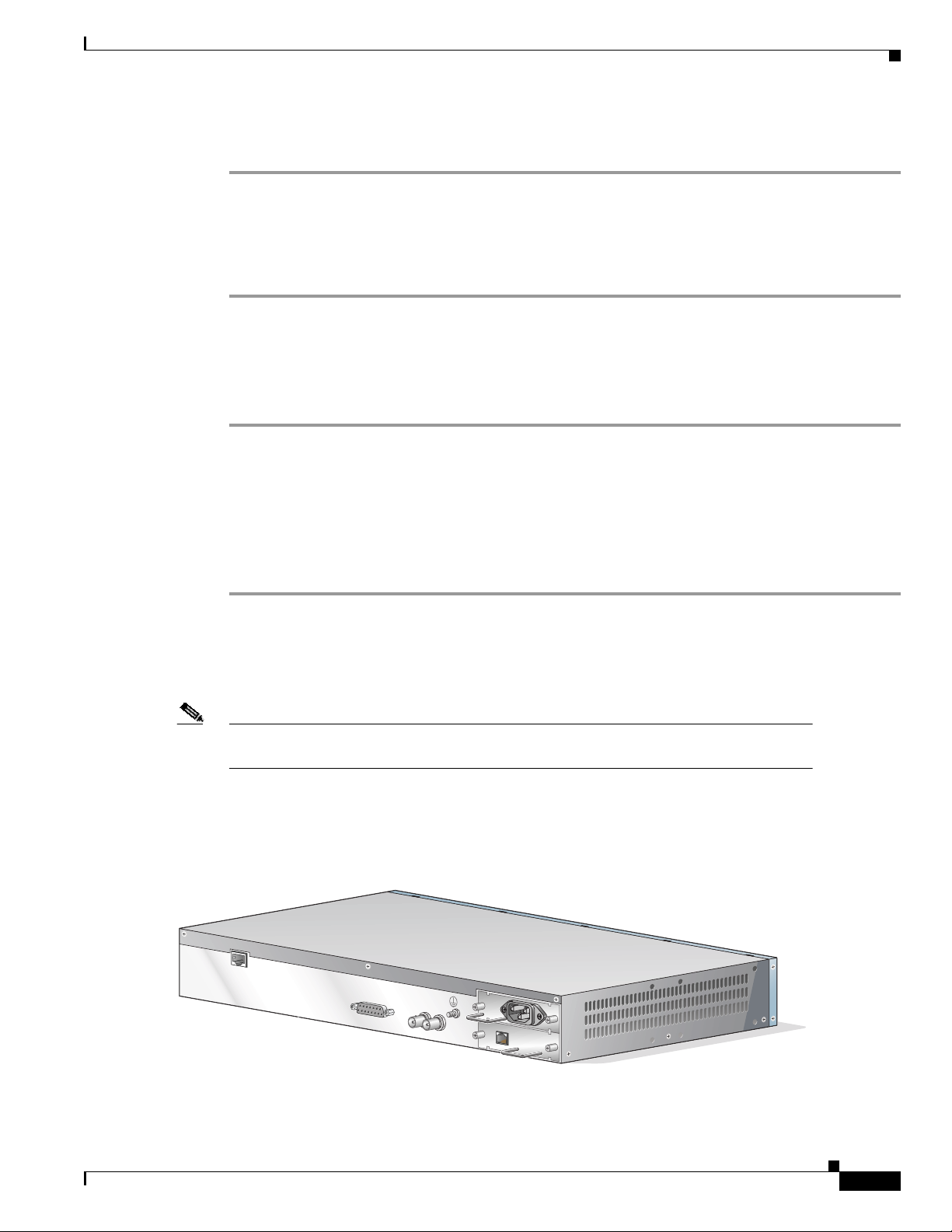
Step 2 Plug the included console cable into the terminal port located at the back of the Cisco 8110 unit (CIT).
(See Figure 3-1).
Step 3 Connect the other end of the cable to the terminal.
Note Refer to Configuration in Chapter 4 for information on using the console management
software for basic configuration.
To connect the terminal using the in-band management software application, see the“Installing a Line
Interface / Compact Subscriber Module (LIM)” section on page 3-4.
Figure 3-1 Rear Panel
CIT
ALARMS
OUT
ETS
IN
8110-PS-110
PS1
PS2
49400
78-11666-01
Cisco 8110 Broadband Network Termination Unit User Guide
3-3
Page 4

Basic Hardware Features
CIT Pinout
Chapter 3 Installation
Table 3-1 shows the serial port pinout configuration.
Table 3-1 Console Serial Port Pinout
Pin Number Signal Mnemonic Signal Name
1 DSR Data Set Ready
2 RXD Receive Data
3 TXD Transmit Data
4 DTR Data Terminal Ready
5 GND Signal Ground
6 DCD Data Carrier Detect
7 CTS Clear to Send
8 RTS Request to Send
LIM Modules
Caution The T1/E1 and T3/E3 connections are restricted to intra-building use only. Do not connect
to exposed plant. Theequipmentisintendedtobeusedbehind a CSU/DSU. The CSU/DSU
should be provided with adequate lightning protection.
Installing a Line Interface / Compact Subscriber Module (LIM)
To install a LIM in your Cisco 8110:
Step 1 Make sure that the LIM module state is OOS (Out Of Service) using the console, or the in-band
management application.
Step 2 Place the module’s card edges into the right and left module guides at the front of the
Cisco 8110
Step 3 Slide in the module until it makes contact with the backplane, then push firmly to mate the connectors
solidly with the backplane.
Step 4 When the module is seated solidly against the backplane, secure the module’s front panel to the Cisco
8110 chassis using the mounting screws on the right and left of the module’s front panel.
Step 5 Securely install and fasten each module to facilitate the installation of the one next to it.
Step 6 Configure the module type to the actual LIM type, using the console or the in-band management
application.
Step 7 Change the module state to Active, using the console or the in-band management application.
3-4
Cisco 8110 Broadband Network Termination Unit User Guide
78-11666-01
Page 5

Chapter 3 Installation
Removing a Line Interface / Compact Subscriber Module (LIM)
To remove a LIM in your Cisco 8110:
Step 1 Change the module state to OOS (Out of Service) using the console, or the in-band management
application
Step 2 Unscrew the right and left mounting screws on the front panel of the module.
Step 3 Remove the module by pulling evenly its mounting screws.
Step 4 Use faceplate panels to protect unused slots from dust and reduce electromagnetic radiation.
Caution If you store modules outside the Cisco 8110 for an extended length of time, place them in
the original packaging (or equivalent packaging providing ESD protection).
Replacing Modules
Basic Hardware Features
Caution All modules are susceptible to electrostatic discharge (ESD) even while installed. Take the
necessary precautions to minimize electrostatic damage while handling modules.
When changing from one type of LIM to another (e.g. from STM-1 to E3) use the following procedure:
Step 1 Change the module state to OOS (Out of Service) by using the console or the in-band management
application.
Step 2 Remove the module
Step 3 Insert the new LIM
Step 4 Change the LIM module type by using the console or the in-band management application.
Step 5 Change the module state to Active by using the console or the in-band management application
Step 6 Reboot the Cisco 8110.
Connecting the External Timing
Timing for the Cisco 8110 can be provided by an external 2048 Kbps signal. The Cisco 8110 outputs the
timing signal, after it has been reconditioned, through its timing output. The timing signal from the Cisco
8110 can be used to synchronize other equipment, including other Cisco 8110 devices.
To connect your Cisco 8110 external timing signals:
78-11666-01
Step 1 Prepare a pair of appropriate coaxial cables with appropriate connectors on the Cisco 8110 side.
Step 2 You may want to mark the ends of the cable so you can identify the wires.
Step 3 Attach one cable into the ETS IN port on the rear panel of your Cisco 8110 unit.
Cisco 8110 Broadband Network Termination Unit User Guide
3-5
Page 6

Basic Hardware Features
Step 4 Attach the other end of the cable connected to the IN connector, to the timing source.
Step 5 If required, attach the other cable into the ETS OUT port on rear panel of the Cisco 8110 unit.
Step 6 Attach the other end of the cable connected to the OUT connector, to the input of the next equipment
requiring external timing.
Step 7 Set timing source to External timing.
Connecting the External alarms
The Cisco 8110 provides one external dry relay alarm indication, and four external alarm input
indications.
To connect your Cisco 8110 external alarm signals:
Step 1 Prepare a shielded cable with connector plug DB15 with shielded backshell.
Step 2 Attach the D-type connector to the ALARMS port on the rear panel of your Cisco 8110 unit. To secure,
tighten the screws on both sides of the connector.
Step 3 Attach the other end of the cable connected to the alarm collection panel.
Step 4 Set the Alarm state to Active.
Chapter 3 Installation
Note Refer to ”External Alarm Configuration”(Chapter 10) for information on using the console
management software for basic external alarms configuration.
3-6
Cisco 8110 Broadband Network Termination Unit User Guide
78-11666-01
Page 7

Chapter 3 Installation
Alarms Pinout
Table 3-2 shows alarm pinout configuration
Table 3-2 Alarm port pinout
Pin Number Signal Name
1 Alarm a input
2 Alarm b input
3 Alarm c input
45 Gnd
67 Alarm Output NO
8 Alarm Output Center
9 Alarm d input
10 Gnd
11 Gnd
12 13 14 15 Alarm Output NC
Removable Power Supply
Removable Power Supply
This section contains the following topics:
• Unpacking the Power Supply
• Basic Hardware Features
• Cable Connections
• Power Supply Installation
• Power Supply LEDs
Unpacking the Power Supply
Upon receipt of, and before opening the power supply, inspect the package for any damage that might
have occurred during shipping. If the package shows any signs of external damage or rough handling,
notify your carrier's representative.
Note When unpacking the power supply be sure to keep all original packing materials. They
might be needed for storing, transporting, or returning the product.
78-11666-01
Cisco 8110 Broadband Network Termination Unit User Guide
3-7
Page 8

Removable Power Supply
All products returned to Cisco, under warranty, must be packed in their original packing materials.
A complete inventory should be carried out before the power supply is installed. The power supply
package should include the following:
• Power supply unit
• Power Supply Installation Manual
Caution All modules are susceptible to electrostatic discharge (ESD) even while installed. Take the
necessary precautions to minimize electrostatic damage while handling modules.
Basic Hardware Features
The power supply is designed to be installed into the Cisco 8110 power supply slot that are located at
the rear of the equipment, and provides the powering for the unit.
A basic configuration will include one power supply. A second power supply may be installed for
redundancy. Each of these modules has one handle for insertion or extraction from the unit and fastening
screws at the sides.
The power supply options are:
Chapter 3 Installation
Type Description
8110-PS-110 110 VAC Power Supply
8110-PS-DC -48 VDC Power Supply
8110-PS-220 220 VAC Power Supply
Caution Connecting 220V to 110V power supplies can cause unrecoverable damage.
Cable Connections
This section contains the following:
• Connecting 8110-PS-220 or 8110-PS-110, page 3-8
• Connecting 8110-PS-DC, page 3-9
Connecting 8110-PS-220 or 8110-PS-110
To connect your 8110-PS-220 or 8110-PS-110 AC Power Supply:
Step 1 Prepare a standard mains cable with IEC 230 connector
Step 2 Snap the cable into the 8110-PS-220 IEC 230 Inlet.
3-8
Cisco 8110 Broadband Network Termination Unit User Guide
78-11666-01
Page 9

Chapter 3 Installation
Connecting 8110-PS-DC
To connect your 8110-PS-DC DC Power Supply:
Step 1 Connect a minimum 14AWG ground wire to the stud located on the rear of the chassis. Fasten with a
lockwasher and screw.
Step 2 Remove the Dinkel connector from the unit
Step 3 Prepare a pair of 14 to 18 (16 recommended) AWG, cables
Step 4 Attach the -48VDC and the RTN connections to the Dinkel connector, and fasten them using the
connector screws. The polarity is detected automatically by the 8110-PS-DC.
Step 5 Snap the connector into the 8110-PS-DC Dinkel receptacle.
Power Supply Installation
This section contains the following:
• Table 3-2 Installing a Power Supply, page 3-9
• Removing a Power Supply, page 3-10
Removable Power Supply
Installing a Power Supply
To install a power supply in your Cisco 8110:
Step 1 Verify that the module state is Out of Service (OOS), using the console or the in-band management
application.
Step 2 If you are installing a 8110-PS-220 verify that the input voltage selector strap, located in the right side
of the module, is in the right position
Step 3 Remove the Faceplate panel that covers the PS slot, if exists.
Step 4 Place the module's card edges into the right and left module guides at the rear of the Cisco 8110
Step 5 Slide in the module until it makes contact with the backplane, then push firmly to mate the connectors
solidly with the backplane.
Step 6 Secure the module's front panel to the Cisco 8110 chassis using the mounting screws on the right and
left of the module's front panel.
Step 7 Securely install and fasten each module to facilitate the installation of the one next to it.
Step 8 Snap the power cable
Step 9 Change the module state to active, using the console or the in-band management application.
78-11666-01
Cisco 8110 Broadband Network Termination Unit User Guide
3-9
Page 10

General Operating Procedures
Removing a Power Supply
To remove a power supply from your Cisco 8110:
Step 1 Change the module state to Out Of Service (OOS) using the console, or the in band management
application
Step 2 2. Remove the power cable
Step 3 3. Unscrew the right and left mounting screws on the front panel of the module.
Step 4 4. Remove the module by pulling its handle.
Step 5 5. Use faceplate panels to protect unused slots from dust and reduce electromagnetic radiation.
Caution The Cisco 8110 ventilation mechanism is not effective if empty slots are not covered with
faceplate panels.
Caution Power cable should always be removed from module before unit is removed from Cisco
8110.
Chapter 3 Installation
Caution If you store modules outside the Cisco 8110 for an extended period of time, place them in
the original packaging (or equivalent packaging providing ESD protection).
Power Supply LEDs
Table 3-3 shows the LEDs for the power supply.
Table 3-3 Cisco 8110 Front Panel PS LEDs
LED Indicator Status Explanation
PS1 Off
PS2 Off
On
Blink
On
Blink
PS in slot 1 Out Of Service
PS in slot 1 Active.
PS in slot 1 failed.
PS in slot 2 Out Of Service
PS in slot 2 Active.
PS in slot 2 failed.
General Operating Procedures
The operation of the Cisco 8110 can be controlled and monitored by the system management application
and by the panel indicators.
Cisco 8110 Broadband Network Termination Unit User Guide
3-10
78-11666-01
Page 11

Chapter 3 Installation
General Operating Procedures
The menu-generated application represents a centralized access point to all the functions that can be
performed by means of the Cisco 8110 System application software.
The various panels are equipped with LED indicators (shown in Table 3-4 and Table 3-5) which are
continuously updated in accordance with information received in response to periodic polling of the
traps and alarms received by the Cisco 8110 System.
Table 3-4 Main Front Panel Section LEDsModel Cisco 8110RFE
LED
Indicator Status Explanation
Power On Unit is powered up
PS1 On
Off
Blink
PS2 On
Off
Blink
Power Supply #1 is active
Power Supply #1 is intentionally out of service
Power Supply #1 is malfunctioning
Power Supply #2 is active
Power Supply #2 is intentionally out of service
Power Supply #2 is malfunctioning
Run On Lights 20 seconds after power up, indicating that
software has been loaded and unit is operational
Tx ON Ethernet data transmit
Rx ON Data received
COL Blinks Collision detected
LED #1 ON
OFF
LED #2 ON
OFF
Port #1 link up
Port #1 link down
Port #2 link up
Port #2 link down
78-11666-01
Table 3-5 LIM Front Panel LEDs for all models
LED
Indicator Status Explanation
ALM On
Off
Tx Off
On Weak
On Strong
Rx Off
On Weak
Alarm present in LIM.
No alarm in LIM.
No cells transmitted in LIM port.
LIM transmitter enabled, no ATM cells transmitted
User cells are being transmitted.
No cells detected in LIM port.
LIM synchronized to receivd signal. No ATM cells
detected
On strong
Flashing
ATM cells detected.
Error during Self Test
Cisco 8110 Broadband Network Termination Unit User Guide
3-11
Page 12

General Operating Procedures
Note OUT of SERVICE - all LEDs are off
ACTIVE MODE - Tx and Rx active (for no alarm)
ACTIVE MODE - Tx +ALM active (with alarm)
STANDBY MODE - All LEDs off (including ALM)
Chapter 3 Installation
3-12
Cisco 8110 Broadband Network Termination Unit User Guide
78-11666-01
 Loading...