

Page 1

Cisco 809 Industrial Integrated Services Router Hardware Installation Guide
First Published: 2016-10-01
Last Modified: 2018-04-30
Americas Headquarters
Cisco Systems, Inc.
170 West Tasman Drive
San Jose, CA 95134-1706
USA
http://www.cisco.com
Tel: 408 526-4000
800 553-NETS (6387)
Fax: 408 527-0883
Page 2

THE SPECIFICATIONS AND INFORMATION REGARDING THE PRODUCTS IN THIS MANUAL ARE SUBJECT TO CHANGE WITHOUT NOTICE. ALL STATEMENTS,
INFORMATION, AND RECOMMENDATIONS IN THIS MANUAL ARE BELIEVED TO BE ACCURATE BUT ARE PRESENTED WITHOUT WARRANTY OF ANY KIND,
EXPRESS OR IMPLIED. USERS MUST TAKE FULL RESPONSIBILITY FOR THEIR APPLICATION OF ANY PRODUCTS.
THE SOFTWARE LICENSE AND LIMITED WARRANTY FOR THE ACCOMPANYING PRODUCT ARE SET FORTH IN THE INFORMATION PACKET THAT SHIPPED WITH
THE PRODUCT AND ARE INCORPORATED HEREIN BY THIS REFERENCE. IF YOU ARE UNABLE TO LOCATE THE SOFTWARE LICENSE OR LIMITED WARRANTY,
CONTACT YOUR CISCO REPRESENTATIVE FOR A COPY.
The following information is for FCC compliance of Class A devices: This equipment has been tested and found to comply with the limits for a Class A digital device, pursuant to part 15
of the FCC rules. These limits are designed to provide reasonable protection against harmful interference when the equipment is operated in a commercial environment. This equipment
generates, uses, and can radiate radio-frequency energy and, if not installed and used in accordance with the instruction manual, may cause harmful interference to radio communications.
Operation of this equipment in a residential area is likely to cause harmful interference, in which case users will be required to correct the interference at their own expense.
The following information is for FCC compliance of Class B devices: This equipment has been tested and found to comply with the limits for a Class B digital device, pursuant to part 15 of
the FCC rules. These limits are designed to provide reasonable protection against harmful interference in a residential installation. This equipment generates, uses and can radiate radio
frequency energy and, if not installed and used in accordance with the instructions, may cause harmful interference to radio communications. However,there is no guarantee that interference
will not occur in a particular installation. If the equipment causes interference to radio or television reception, which can be determined by turning the equipment off and on, users are
encouraged to try to correct the interference by using one or more of the following measures:
• Reorient or relocate the receiving antenna.
• Increase the separation between the equipment and receiver.
• Connect the equipment into an outlet on a circuit different from that to which the receiver is connected.
• Consult the dealer or an experienced radio/TV technician for help.
Modifications to this product not authorized by Cisco could void the FCC approval and negate your authority to operate the product.
The Cisco implementation of TCP header compression is an adaptation of a program developed by the University of California, Berkeley (UCB) as part of UCB’s public domain version of
the UNIX operating system. All rights reserved. Copyright©1981, Regents of the University of California.
NOTWITHSTANDING ANY OTHER WARRANTY HEREIN, ALL DOCUMENT FILES AND SOFTWARE OF THESE SUPPLIERS ARE PROVIDED "AS IS" WITH ALL FAULTS.
CISCO AND THE ABOVE-NAMED SUPPLIERS DISCLAIM ALL WARRANTIES, EXPRESSED OR IMPLIED, INCLUDING, WITHOUT LIMITATION, THOSE OF
MERCHANTABILITY, FITNESS FOR A PARTICULAR PURPOSE AND NONINFRINGEMENT OR ARISING FROM A COURSE OF DEALING, USAGE, OR TRADE PRACTICE.
IN NO EVENT SHALL CISCO OR ITS SUPPLIERS BE LIABLE FOR ANY INDIRECT, SPECIAL, CONSEQUENTIAL, OR INCIDENTAL DAMAGES, INCLUDING, WITHOUT
LIMITATION, LOST PROFITS OR LOSS OR DAMAGE TO DATA ARISING OUT OF THE USE OR INABILITY TO USE THIS MANUAL, EVEN IF CISCO OR ITS SUPPLIERS
HAVE BEEN ADVISED OF THE POSSIBILITY OF SUCH DAMAGES.
Any Internet Protocol (IP) addresses and phone numbers used in this document are not intended to be actual addresses and phone numbers. Any examples, command display output, network
topology diagrams, and other figures included in the document are shown for illustrative purposes only. Any use of actual IP addresses or phone numbers in illustrative content is unintentional
and coincidental.
All printed copies and duplicate soft copies of this document are considered uncontrolled. See the current online version for the latest version.
Cisco has more than 200 offices worldwide. Addresses and phone numbers are listed on the Cisco website at www.cisco.com/go/offices.
Cisco and the Cisco logo are trademarks or registered trademarks of Cisco and/or its affiliates inthe U.S. and other countries. To view a list of Cisco trademarks, go to this URL: www.cisco.com
go trademarks. Third-party trademarks mentioned are the property of their respective owners. The use of the word partner does not imply a partnership relationship between Cisco and any
other company. (1721R)
©
2016–2018 Cisco Systems, Inc. All rights reserved.
Page 3

CONTENTS
PREFACE
CHAPTER 1
Preface v
Preface v
Product Overview 1
General Description 1
LEDs 5
SKU Information 7
Memory 8
Hardware Features 8
Supported Cisco Antennas and Cables 9
ANT-3-4G2G1-O 10
ANT-4G-OMNI-OUT-N 10
ANT-4G-PNL-OUT-N 11
ANT-4G-SR-OUT-TNC 12
ANT-4G-DP-IN-TNC 13
4G-LTE-ANTM-O-3-X 14
4G-ANTM-OM-CM 15
CHAPTER 2
Antenna Extension 4G-AE015-R 15
Antenna Extension 4G-AE010-R 16
Modem Support 16
Power Supply 16
RJ45 Ports 17
Accessories 18
Installing the Router 19
Equipment, Tools, and Connections 20
Cisco 809 Industrial Integrated Services Router Hardware Installation Guide
iii
Page 4

Contents
Installing the Router 21
Accessing the SIM Cards 21
Modems 22
Installing Antennas 23
Mounting on a Wall, Table, or Other Flat Surface 24
Installing a DIN Rail 25
Installing the Router Ground Connection 27
CHAPTER 3
APPENDIX A
Connecting the Router 31
Preventing Damage to the Router 31
Connecting a Terminal or PC to the Console Port 32
Connecting to DC Power 32
Plugs and Pin-Outs 33
Wiring the DC Power and Alarm Connections 33
Connecting the Router to the AC-Input Power Supply 35
Connecting the Router to the DC Source. 36
Connecting the Power Converter to an AC Power Source 38
Verifying Connections 40
Technical Specifications 41
Router Specifications 41
Cisco 809 Industrial Integrated Services Router Hardware Installation Guide
iv
Page 5

Preface
Preface
• Preface, on page v
This preface describes the objectives, audience, organization, and conventions of this guide and describes
related documents that have additional information.
Objective
This guide provides an overview and explains how to install, connect, and perform initial configuration for
the Cisco 809 ISR. Previous versions of this guide contained additional configuration information which has
now been relocated to the Cisco IR800 Integrated Services Router Software Configuration Guide.
Audience
This guide is intended for people who have a high level of technical ability, although they may not have
experience with Cisco software.
Conventions
This section describes the conventions used in this guide.
Note
Caution
Tip
Means reader take note. Notes contain helpful suggestions or references to additional information and material.
This symbol means reader be careful. In this situation, you might do something that could result in equipment
damage or loss of data.
Means the following information will help you solve a problem . The tip information might not be
troubleshooting or even an action, but could be useful information.
Cisco 809 Industrial Integrated Services Router Hardware Installation Guide
v
Page 6

Preface
Preface
Safety Warnings
IMPORTANT SAFETY INSTRUCTIONS
This warning symbol means danger. You are in a situation that could
cause bodily injury. Before you work on any equipment, be aware of
the hazards involved with electrical circuitry and be familiar with
standard practices for preventing accidents. Use the statement number
provided at the end of each warning to locate its translation in the
translated safety warnings that accompanied this device. Statement 1071
SAVE THESE INSTRUCTIONS
Waarschuwing
Varoitus
Attention
BELANGRIJKE VEILIGHEIDSINSTRUCTIES
Dit waarschuwingssymbool betekent gevaar. U verkeert in een situatie
die lichamelijk letsel kan veroorzaken. Voordat u aan enige apparatuur
gaat werken, dient u zich bewust te zijn van de bij elektrische
schakelingen betrokken risico's en dient u op de hoogte te zijn van de
standaard praktijken om ongelukken te voorkomen. Gebruik het nummer
van de verklaring onderaan de waarschuwing als u een vertaling van de
waarschuwing die bij het apparaat wordt geleverd, wilt raadplegen.
BEWAAR DEZE INSTRUCTIES
TÄRKEITÄ TURVALLISUUSOHJEITA
Tämä varoitusmerkki merkitsee vaaraa. Tilanne voi aiheuttaa ruumiillisia
vammoja. Ennen kuin käsittelet laitteistoa, huomioi sähköpiirien
käsittelemiseen liittyvät riskit ja tutustu onnettomuuksien yleisiin
ehkäisytapoihin. Turvallisuusvaroitusten käännökset löytyvät laitteen
mukana toimitettujen käännettyjen turvallisuusvaroitusten joukosta
varoitusten lopussa näkyvien lausuntonumeroiden avulla.
SÄILYTÄ NÄMÄ OHJEET
IMPORTANTES INFORMATIONS DE SÉCURITÉ
Ce symbole d'avertissement indique un danger. Vous vous trouvez dans
une situation pouvant entraîner des blessures ou des dommages corporels.
Avant de travailler sur un équipement, soyez conscient des dangers liés
aux circuits électriques et familiarisez-vous avec les procédures
couramment utilisées pour éviter les accidents. Pour prendre
connaissance des traductions des avertissements figurant dans les
consignes de sécurité traduites qui accompagnent cet appareil,
référez-vous au numéro de l'instruction situé à la fin de chaque
avertissement.
CONSERVEZ CES INFORMATIONS
Cisco 809 Industrial Integrated Services Router Hardware Installation Guide
vi
Page 7

Preface
Preface
Warnung
Avvertenza
Advarsel
WICHTIGE SICHERHEITSHINWEISE
Dieses Warnsymbol bedeutet Gefahr. Sie befinden sich in einer Situation,
die zu Verletzungen führen kann. Machen Sie sich vor der Arbeit mit
Geräten mit den Gefahren elektrischer Schaltungen und den üblichen
Verfahren zur Vorbeugung vor Unfällen vertraut. Suchen Sie mit der
am Ende jeder Warnung angegebenen Anweisungsnummer nach der
jeweiligen Übersetzung in den übersetzten Sicherheitshinweisen, die
zusammen mit diesem Gerät ausgeliefert wurden.
BEWAHREN SIE DIESE HINWEISE GUT AUF.
IMPORTANTI ISTRUZIONI SULLA SICUREZZA
Questo simbolo di avvertenza indica un pericolo. La situazione potrebbe
causare infortuni alle persone. Prima di intervenire su qualsiasi
apparecchiatura, occorre essere al corrente dei pericoli relativi ai circuiti
elettrici e conoscere le procedure standard per la prevenzione di incidenti.
Utilizzare il numero di istruzione presente alla fine di ciascuna
avvertenza per individuare le traduzioni delle avvertenze riportate in
questo documento.
CONSERVARE QUESTE ISTRUZIONI
VIKTIGE SIKKERHETSINSTRUKSJONER
Dette advarselssymbolet betyr fare. Du er i en situasjon som kan føre
til skade på person. Før du begynner å arbeide med noe av utstyret, må
du være oppmerksom på farene forbundet med elektriske kretser, og
kjenne til standardprosedyrer for å forhindre ulykker. Bruk nummeret
i slutten av hver advarsel for å finne oversettelsen i de oversatte
sikkerhetsadvarslene som fulgte med denne enheten.
Aviso
¡Advertencia!
TA VARE PÅ DISSE INSTRUKSJONENE
INSTRUÇÕES IMPORTANTES DE SEGURANÇA
Este símbolo de aviso significa perigo. Você está em uma situação que
poderá ser causadora de lesões corporais. Antes de iniciar a utilização
de qualquer equipamento, tenha conhecimento dos perigos envolvidos
no manuseio de circuitos elétricos e familiarize-se com as práticas
habituais de prevenção de acidentes. Utilize o número da instrução
fornecido ao final de cada aviso para localizar sua tradução nos avisos
de segurança traduzidos que acompanham este dispositivo.
GUARDE ESTAS INSTRUÇÕES
INSTRUCCIONES IMPORTANTES DE SEGURIDAD
Este símbolo de aviso indica peligro. Existe riesgo para su integridad
física. Antes de manipular cualquier equipo, considere los riesgos de la
corriente eléctrica y familiarícese con los procedimientos estándar de
prevención de accidentes. Al final de cada advertencia encontrará el
número que le ayudará a encontrar el texto traducido en el apartado de
traducciones que acompaña a este dispositivo.
GUARDE ESTAS INSTRUCCIONES
Cisco 809 Industrial Integrated Services Router Hardware Installation Guide
vii
Page 8
Preface
Preface
Varning!
VIKTIGA SÄKERHETSANVISNINGAR
Denna varningssignal signalerar fara. Du befinner dig i en situation som
kan leda till personskada. Innan du utför arbete på någon utrustning
måste du vara medveten om farorna med elkretsar och känna till vanliga
förfaranden för att förebygga olyckor. Använd det nummer som finns i
slutet av varje varning för att hitta dess översättning i de översatta
säkerhetsvarningar som medföljer denna anordning.
SPARA DESSA ANVISNINGAR
viii
Aviso
INSTRUÇÕES IMPORTANTES DE SEGURANÇA
Este símbolo de aviso significa perigo. Você se encontra em uma situação
em que há risco de lesões corporais. Antes de trabalhar com qualquer
equipamento, esteja ciente dos riscos que envolvem os circuitos elétricos
e familiarize-se com as práticas padrão de prevenção de acidentes. Use
o número da declaração fornecido ao final de cada aviso para localizar
sua tradução nos avisos de segurança traduzidos que acompanham o
dispositivo.
GUARDE ESTAS INSTRUÇÕES
Cisco 809 Industrial Integrated Services Router Hardware Installation Guide
Page 9
Preface
Preface
Advarsel
VIGTIGE SIKKERHEDSANVISNINGER
Dette advarselssymbol betyder fare. Du befinder dig i en situation med
risiko for legemesbeskadigelse. Før du begynder arbejde på udstyr, skal
du være opmærksom på de involverede risici, der er ved elektriske
kredsløb, og du skal sætte dig ind i standardprocedurer til undgåelse af
ulykker. Brug erklæringsnummeret efter hver advarsel for at finde
oversættelsen i de oversatte advarsler, der fulgte med denne enhed.
GEM DISSE ANVISNINGER
Cisco 809 Industrial Integrated Services Router Hardware Installation Guide
ix
Page 10
Preface
Preface
Warning
Warning
Warning
Warning
When installing the product, please use the provided or designated connection cables/power cables/AC
adaptors. Using any other cables/adaptors could cause a malfunction or a fire. Electrical Appliance and Material
Safety Law prohibits the use of UL-certified cables (that have the “UL” shown on the code) for any other
electrical devices than products designated by CISCO. The use of cables that are certified by Electrical
Appliance and Material Safety Law (that have “PSE” shown on the code) is not limited to CISCO-designated
products. Statement 371
Read the wall-mounting instructions carefully before beginning installation. Failure to use the correct hardware
or to follow the correct procedures could result in a hazardous situation to people and damage to the system.
Statement 378
To avoid electric shock, do not connect safety extra-low voltage (SELV) circuits to telephone-network voltage
(TNV) circuits. LAN ports contain SELV circuits, and WAN ports contain TNV circuits. Some LAN and
WAN ports both use RJ-45 connectors. Use caution when connecting cables. Statement 1021
This equipment must be grounded. Never defeat the ground conductor or operate the equipment in the absence
of a suitably installed ground conductor. Contact the appropriate electrical inspection authority or an electrician
if you are uncertain that suitable grounding is available . Statement 1024
x
Warning
If the symbol of suitability with an overlaid cross appears above a port, you must not connect the port to a
public network that follows the European Union standards. Connecting the port to this type of public network
can cause severe personal injury or can damage the unit. Statement 1031
Warning
Connect the unit only to DC power source that complies with the safety extra-low voltage (SELV) requirements
in IEC 60950 based safety standards. Statement 1033
Cisco 809 Industrial Integrated Services Router Hardware Installation Guide
Page 11
Preface
Preface
Warning
Warning
Warning
Warning
Warning
When installing or replacing the unit, the ground connection must always be made first and disconnected last.
Statement 1046
Do not locate the antenna near overhead power lines or other electric light or power circuits, or where it can
come into contact with such circuits. When installing the antenna, take extreme care not to come into contact
with such circuits, because they may cause serious injury or death. For proper installation and grounding of
the antenna, please refer to national and local codes (for example, U.S.:NFPA 70, National Electrical Code,
Article 810, Canada: Canadian Electrical Code, Section 54). Statement 1052
No user-serviceable parts inside. Do not open. Statement 1073
Installation of the equipment must comply with local and national electrical codes. Statement 1074
Only trained and qualified personnel should be allowed to install, replace, or service this equipment. Statement
1030
Warning
Warning
Warning
Warning
Read the installation instructions before connecting the system to the power source. Statement 1004
Ultimate disposal of this product should be handled according to all national laws and regulations. Statement
1040
The covers are an integral part of the safety design of the product. Do not operate the unit without the covers
installed. Statement 1077
Hot surface. Statement 1079
Cisco 809 Industrial Integrated Services Router Hardware Installation Guide
xi
Page 12
Preface
Preface
Warning
Note
The intra-building ports of the equipment or subassembly is suitable for connection to intra-building or
unexposed wiring or cabling only. The intra-building port(s) of the equipment or subassembly MUST NOT
be metallically connected to interfaces that connect to the OSP or its wiring.These interfaces are designed for
use as intra-building interfaces only (Type 2 or Type 4 ports as described in GR-1089-CORE) and require
isolation from the exposed OSP cabling. The addition of Primary Protectors is not sufficient protection in
order to connect these interfaces metallically to OSP wiring.
This equipment is suitable for installation in Network Telecommunications Facilities and locations where
NEC applies. This equipment is suitable for installation as part of the Common Bonding Network (CBN).
Related Documentation
• Cisco IOS Release Notes
• Cisco IR800 Integrated Services Router Software Configuration Guide.
• Getting Started and Product Document of Compliance for the Cisco IR809 Integrated Services Router
• Contains Product Compliance and Safety information as well as Declaration of Conformity
• Hazardous Locations Standards and Marking Strings
• EMC Information
Searching Cisco Documents
To search an HTML document using a web browser, press Ctrl-F (Windows) or Cmd-F (Apple). In most
browsers, the option to search whole words only, invoke case sensitivity, or search forward and backward is
also available.
To search a PDF document in Adobe Reader, use the basic Find toolbar (Ctrl-F) or the Full Reader Search
window (Shift-Ctrl-F). Use the Find toolbar to find words or phrases within a specific document. Use the
Full Reader Search window to search multiple PDF files simultaneously and to change case sensitivity and
other options. Adobe Reader’s online help has more information about how to search PDF documents.
xii
Cisco 809 Industrial Integrated Services Router Hardware Installation Guide
Page 13

CHAPTER 1
Product Overview
This chapter provides an overview of the features available for the Cisco 809 Integrated Services Routers
(ISRs).
Note
For compliance and safety information, see Regulatory Compliance and Safety Information for Cisco 800
Series
• General Description, on page 1
• SKU Information, on page 7
• Hardware Features, on page 8
• Supported Cisco Antennas and Cables, on page 9
• Power Supply, on page 16
• RJ45 Ports, on page 17
• Accessories, on page 18
General Description
The Cisco 809 Integrated Services Router (IR809), part of the Cisco Integrated Services Routers Generation
2 (ISR G2) Family, is designed as a next generation ruggedized fixed form factor router. It is a small-form
factor router with LTE, for use in ATM, POS, Telemetry, Billboards, Enterprise Fleet markets, Utilities and
other SCADA (Supervisory Control and Data Acquisition) environments.
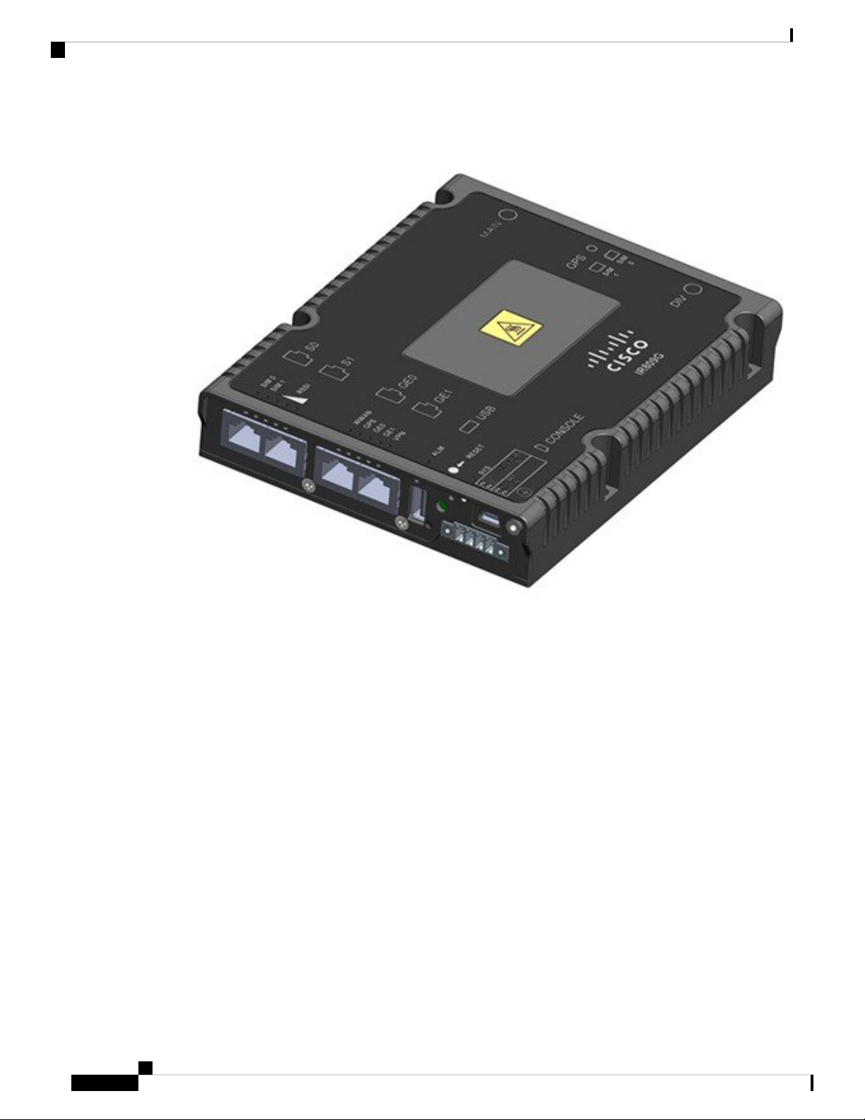
The following figure shows the IR809.
Cisco 809 Industrial Integrated Services Router Hardware Installation Guide
1
Page 14
General Description
Product Overview
Figure 1: Cisco IR809 Integrated Services Router
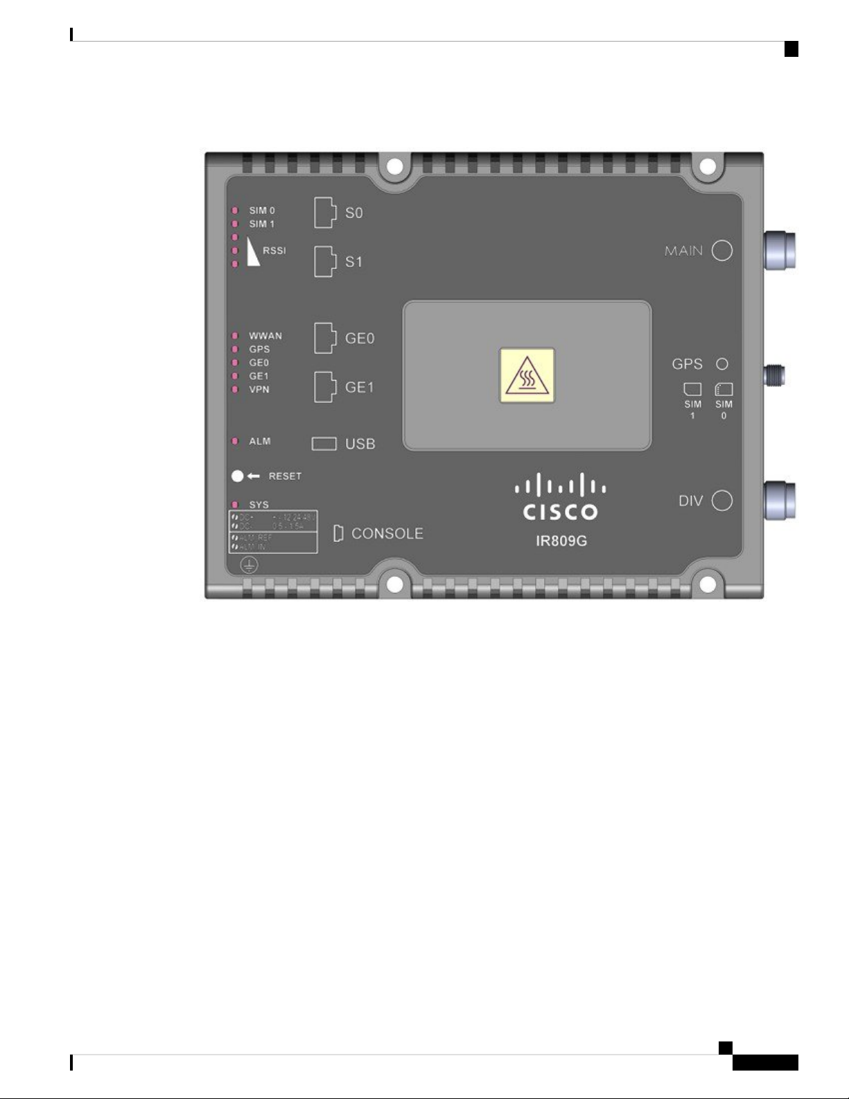
The following figure shows the front panel details of the Cisco IR809.
Cisco 809 Industrial Integrated Services Router Hardware Installation Guide
2
Page 15
Product Overview
General Description
Figure 2: Cisco IR809 Front Panel
Grounding Point8S0 RS232 DCE/RS485 Combo Port1
Mini type-B USB console/debug port9S1 RS232 DTE only2
SYS LED10GE0 (10/100/1000)3
Alarm LED11GE1 (10/100/1000)4
WAN/WWAN LEDs12USB 2.0 (Type-A Host Port)5
SIM Card LEDs13RESET Button6
DC Power/Alarm Connector7
Note
LEDs are viewable from the top and from the front of the IR809.
The following figure shows the back panel details of the Cisco IR809.
Cisco 809 Industrial Integrated Services Router Hardware Installation Guide
3
Page 16
General Description
Product Overview
Figure 3: Cisco IR809 Back Panel
DIV TNC connector for 4G Modem1
SMA connector for GPS2
SIM0 and SIM1 Card Slots3
MAIN TNCconnector for 4G Modem4
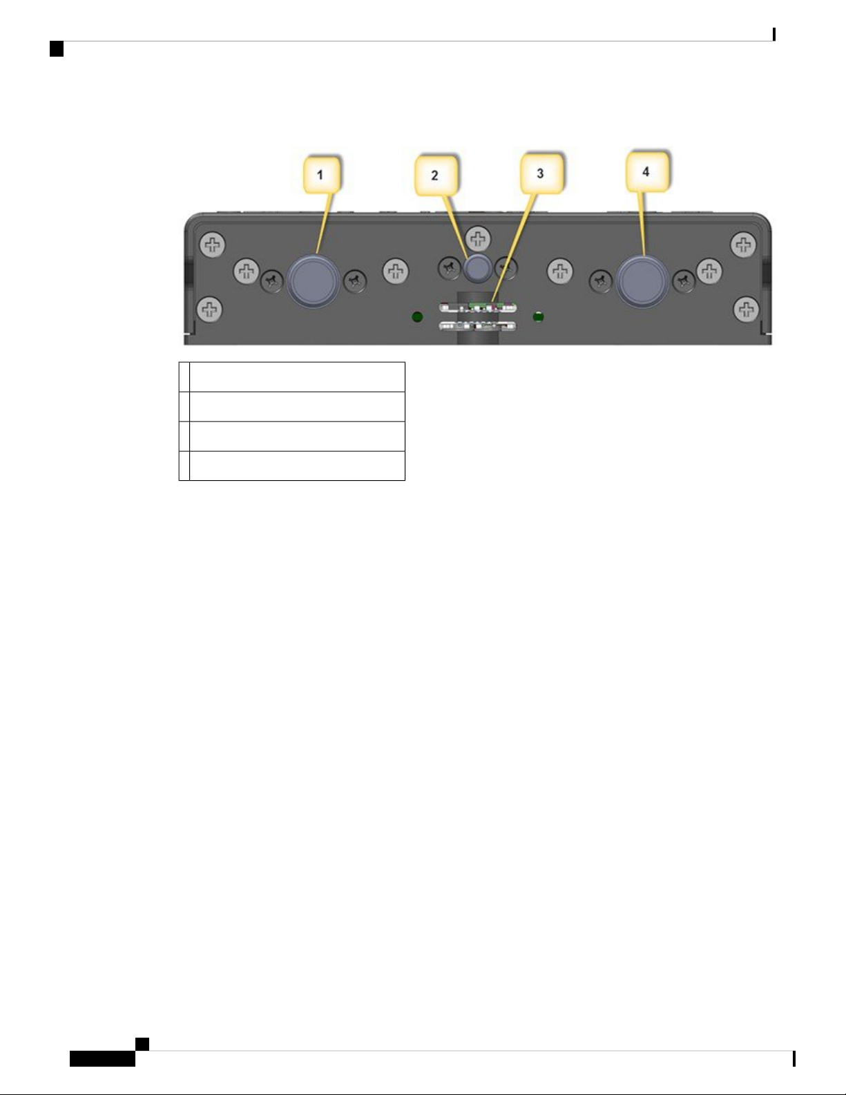
The following figure shows the top cover details of the Cisco IR809.
Cisco 809 Industrial Integrated Services Router Hardware Installation Guide
4
Page 17
Product Overview
LEDs
Figure 4: Cisco IR809 Top Cover
LEDs
The following table describes the LEDs for the Cisco 809 ISR.
Cisco 809 Industrial Integrated Services Router Hardware Installation Guide
5
Page 18

LEDs
Product Overview
Table 1: LED Descriptions
DescriptionActivityLED
SYS
Power and System
Status
Alarm Input StatusALM
VPNVPN_OK
Innormaloperating mode,aftersystem boots.(typicallyabout
2 minutes)
Off — No power
Green Steady on — Router is reachable, and all interfaces are up
and functioning properly
Green Flashing — Router is reachable, and no interface is in a
failed state
Amber Steady on — Router is unreachable (An external interface
of the router, that prevents the router from being remotely managed,
is in a critical failed state)
Amber Flashing — Router is reachable, but at least one of the
interfaces is in a non-critical failed state (functionality of that
interface is affected)
In bootup mode (during the first 60 seconds after powerup)
Green Steady on — Router is bootingy
Amber Steady on — Router has a system hardware failure
Off — Normal operation
Red - Alarm State on the Alarm Input
Off — No VPN tunnel
(10/100/1000)WAN
0
GE0
(10/100/1000)WAN
1
Steady Green — At least one VPN tunnel is up
Link StatusGE0
Off — No link
Steady Green — Link is up
Flashing — Transmitting and Receiving data
GPS StatusGPS
Off — GPS not configured
On — GPS configured
Slow Flash — GPS Acquiring in Standalone GPS
Fast Flash — GPS Acquiring in Assisted GPS
Note
Slow Flash is defined as the LED will be on for 0.25
seconds and off for 0.75 seconds.Fast Flash is defined
as the LED will be on for 0.25 seconds and off for 0.25
seconds.
Cisco 809 Industrial Integrated Services Router Hardware Installation Guide
6
Page 19

Product Overview
SKU Information
DescriptionActivityLED
WWAN
RSSI
Table 2: RSSI LEDs
-90dBm
Wireless WAN
Activity
Received Signal
Strength Indication
SIM cardsSIM0/SIM1
Off-75 to -60dBm
Green
Off — Modem not powered on On — Modem is powered on and
connected but not transmitting or receiving Slow Blink — Modem
is powered on and searching for connection
Fast Blink — Modem is transmitting or receiving.
The RSSI LEDs are a 3 LED bar graph to indicate signal strength.
Their functionality is described in the RSSI LEDs table below.
Off — No USIM
Green — USIM installed and active
RSSI (0)RSSI (1)RSSI (2)RSSI
Green/AmberGreenGreen
OffOffOff< -110dBm
On - AmberOffOff-110 to
On - GreenOffOff-90 to -75dBm
On - GreenOn -
> -60dBm
SKU Information
The following table lists the different SKUs available for the Cisco 809 Integrated Services Router. All SKUs
support external antenna.
Table 3: Supported SKUs for Cisco IR809s
DescriptionSKU ID
IR809G-LTE-NA-K9
IR809G-LTE-VZ-K9
Multimode 4G/3G/2G connectivity to cellular networks operating in LTE 1900 MHz (band 2 PCS), 1700/2100
MHz (band 4 AWS), 850 MHz (band 5), 700 MHz (band 17) and 1900 MHz (band 25 extended PCS)
frequencies; backward-compatible with UMTS and HSPA+: 850 MHz (band 5), 900 MHz (band 8), 1900
MHz (band 2 PCS), and 1700/2100 MHz (band 4 AWS).
Multimode 4G/3G/2G connectivity to cellular networks operating in LTE 700 MHz (band 13), 1700/2100
MHz (band 4 AWS), or 1900 MHz (band 25 extended PCS) frequencies; backward-compatible with EVDO
Rev A/CDMA 1x BC0, BC1, BC10.
On Green
On - GreenOn -
Green
Cisco 809 Industrial Integrated Services Router Hardware Installation Guide
7
Page 20

Memory
Product Overview
DescriptionSKU ID
IR809G-LTE-GA-K9
IR809G-LTE-LA-K9
Memory
Multimode 4G/3G/2G connectivity to cellular networks operating in LTE 800 MHz (band 20), 900 MHz
(band 8), 1800 MHz (band 3), 2100 MHz (band 1), or 2600 MHz (band 7) frequencies; backward-compatible
with UMTS and HSPA+: 850 MHz (band 5), 900 MHz (band 8),1900 MHz (band 2), and 2100 MHz (band
1).
Multimode 4G/3G connectivity to cellular networks operating in FDD LTE 2100 MHz (band 1), 1800 MHz
(band 3), 850 MHz (band 5), 2600 (band 7), 900 (band 8), 850 (band18, band19), 1500 (band 21), 700 (band
28) and TDD LTE 2600 (band 38), 1900 (band 39), 2300 (band 40) and 2500 (band 41); backward-compatible
with WCDMA 2100 MHz (band 1), 850 MHz (band 5), 800 MHz (band 6, band 19), 900 MHz (band 8),
1700 MHz (band 9) and TD-SCDMA 1900 MHz (band 39).
The Cisco IR809 uses flash memory and main memory. The flash memory contains the Cisco IOS software
image and the boot flash contains the ROMMON boot code. All memory components are factory default and
not upgradeable by the end user.
The following table shows the memory allocation.
Table 4: Cisco IR809 Memory
SpecificationMemory
2GBDefault and maximum DRAM
Hardware Features
This section provides an overview of hardware features for the Cisco 809 ISR.
Platform Features for Cisco IR809
The following lists the hardware platform features for the Cisco IR809.
• Mechanical/Environmental
• Form-factor, Width X Length X Height: 5.05" x 6.27" x 1.15" (12.8 x 15.9 x 2.9 cm)
• Mounting Options: Wall, floor, cabinet, shelf, and DIN Rail mounting
• -40C to +60C operating temperature (outside ambient)
• 5Kft altitude
• External Power Entry
• 9.6V to 60VDC; Nominal: 12 to 48VDC
8 GB eMMC (4GB usable)Default and maximum flash memory
16MBBoot Flash
Cisco 809 Industrial Integrated Services Router Hardware Installation Guide
8
Page 21

Product Overview
Supported Cisco Antennas and Cables
• 4-pin 3.8 mm EURO power connector
• External Reset/Recovery Push Button
• WWAN Modem
• 1x internal Mini PCIe slot for Single multi-band 2G/3G/4G/LTE cellular modem
• Dual USIM Card slots (2 external SIM card slots). Provides Redundancy and multi-homing
capabilities over LTE and HSPA-based networks.
• WAN Ports
• 2x RJ45 10/100/1000 Gigabit Ethernet
• Serial Ports
• 1 x RJ45 RS232 DTE Port
• 1 x RJ45 RS232/RS485 DCE Port (SW-configurable)
• USB Ports
• 1x USB2.0 Type A External Host Port
• 1x USB2.0 Type Mini-B External Debug/Console Device Port
• Compliance
• Telcordia GR-3108 Class 2 deployment
• Class A EMC or better
• RoHS6
• IP30 compliant when vertical, IP40 compliant when mounted flat on a horizontal surface
Reset Button
The Reset button resets the router configuration to the default configuration set by the factory. To restore the
router configuration to the default configuration set by the factory, use a standard size #1 paper clip with wire
gauge 0.033 inch or smaller and simultaneously press the reset button while applying power to the router.
The reset button works in two different manners:
• With the reset button pressed for less than 10 seconds, the IR809 will load with saved start-up configuration
at that time.
• With the reset button pressed longer than 10 seconds, the NVRAM file system is erased and the IR809
boots up with Initial Configuration.
Supported Cisco Antennas and Cables
The Cisco IR809 ships without antennas. All antennas are options that can be ordered separately.
Cisco 809 Industrial Integrated Services Router Hardware Installation Guide
9
Page 22

ANT-3-4G2G1-O
Product Overview
There are two TNC connectors on the backside of the device. The TNC connectors are used to connect to the
4G modem. The SMA connector is for the GPS antenna.
Note
Before choosing your antenna type and installation scenario, read through the following information.
This section lists the supported Antennas and Cables for the Cisco IR809. For detailed information about
Cisco Antennas, please refer to the following guides:
• Connected Grid Antennas Installation Guide:
http://www.cisco.com/c/en/us/td/docs/routers/connectedgrid/antennas/installing/cg_antenna_install_guide.html
• Antennas for the Cisco 800 Series Routers:
http://www.cisco.com/c/en/us/support/routers/800-series-routers/products-installation-guides-list.html
Note
An antenna lighting arrestor must be used when an antenna is installed outdoors. Install per the country’s
national electrical code requirements for lightning protection. The Lightning Arrestor for LTE antenna’s is
CGR-LA-NF-NF or CGR-LA-NM-NF.
The following antennas and cables are available:
ANT-3-4G2G1-O
Description: Cisco Quinta 3 element 3-in-1 transportation antenna
• 2x 4G cellular, 1xGPS
• Color: Black radome
• RoHS compliant
• Environment: Outdoor
ANT-4G-OMNI-OUT-N
Description: Cisco outdoor omnidirectional antenna for 2G, 3G, and 4G LTE cellular
• UV-stable radome
• Mast-mounting bracket
• Applicable for both 2G and 3G solutions
• Domestic LTE 700 band and global LTE 2600 band
• Domestic cellular and global GSM
• WiMAX 2300 and 2500
Electrical Specifications:
Cisco 809 Industrial Integrated Services Router Hardware Installation Guide
10
Page 23

Product Overview
ANT-4G-PNL-OUT-N
• Frequency ranges: 698 to 960 MHz, 1710 to 2170 MHz, and 2300 to 2700 MHz
• Nominal gain (dBi): 698 to 960 MHz = 1.5 dBi, and 1710 to 2700 MHz = 3.5 dBi
• 3 dB beam width (E plane): 698 to 960 MHz = 81 degrees, 1710 to 2170 MHz = 75 degrees, and 2300
to 2700 MHz = 100 degrees
• 3 dB beam width (H plane): 360 degrees, omnidirectional
• Polarization: vertical and linear
• Nominal impedance: 50 ohms
• VSWR: < 2.5:1 (698 to 960 MHz) and < 2.0:1 (1710 to 2690 MHz)
• Radiation pattern: omnidirectional
Mechanical Specifications:
• Mount style: mast mount, upright position only
• Environment: outdoor
• Connector: N-type socket
• Antenna length (height): 9.8 x 1 in. (24.9 x 2.45 cm)
• Weight: 1.5 lb. (0.68 kg)
• Dimensions (H x Outside dimensions): 9.8 x 1 in. (248 x 24.5 mm)
• Operating temperature range: -22° to 158°F (-30° to 70°C)
• Storage temperature: -40° to 185°F (-40° to 85°C)
• Maximum power: 20W
• Radome: polycarbonate, UV, white
• Material substance compliance: ROHS compliant
ANT-4G-PNL-OUT-N
Description: Cisco multiband panel outdoor 4G LTE antenna:
• Supports 3G and 4G LTE solutions
• Multiband
• Wall mount and mast mount
• Indoor and outdoor
• Dual type-N socket connector
Electrical specifications:
• Frequency ranges: 698 to 960 MHz and 1710 to 2700 MHz
• VSWR: 2.0:1 maximum
Cisco 809 Industrial Integrated Services Router Hardware Installation Guide
11
Page 24

ANT-4G-SR-OUT-TNC
Product Overview
• Gain: 5.5 to 10.5 dBi (698 to 960 MHz) and 6.5 to 9.0 dBi (1710 to 2700 MHz)
• 3-dB beam width (vertical plane): 55 to 70 degrees = 698 to 960 MHz, 53 to 98 degrees = 1710 to 2200
MHz, 60 to 70 degrees = 2200 to 2500 MHz, and 55 to 70 degrees = 2500 to 2700 MHz
• 3-dB beam width (horizontal plane): 55 to 70 degrees = 698 to 960 MHz and 50 to 90 degrees = 1710
to 2200 MHz
• F/B ratio: > 15 dB, typical 20 dB = 698 to 960 MHz, and > 17 dB, typical 23 dB = 1700 to 2700 MHz
• Isolation: > 30 dB
• Polarization: slant +/- 45 degrees
• Nominal impedance: 50 ohms
• Radiation pattern: directional
Mechanical specifications:
• Mount style: wall or mast mount
• Environment: outdoor
• Connector: dual type N female (direct connect or dual 12 in (30 cm))
• Antenna length (height): 11.6" (2.95 cm)
• Temperature Range (Operating): -22 to 158-degrees F (-30 to 70° C)
• Storage temperature: -40 to +85° C
• Wind rating: 160 km/H
• IP rating: IP54
• Radome: polycarbonate, UV resistant, white
• Material substance compliance: ROHS compliant
ANT-4G-SR-OUT-TNC
Description: Cisco integrated 4G LTE low-profile outdoor saucer antenna:
• Applicable for both 3G and 4G LTE solutions
• Domestic LTE 700 band and global LTE 2600 band
• Domestic cellular and global GSM
• Weatherproof UV stable radome
• Performance optimized
• Excellent flame rating
Electrical specifications:
• Frequency ranges: 698 to 960 MHz and 1710 to 2700 MHz
Cisco 809 Industrial Integrated Services Router Hardware Installation Guide
12
Page 25

Product Overview
ANT-4G-DP-IN-TNC
• Peak gain with 1-ft cable: 1.5 dBi (698 to 960 MHz) and 3.7 dBi (1710 to 2700 MHz)
• Peak gain with 15-ft cable: 0.8 dBi (698 to 960 MHz) and 0.2 dBi (1710 to 2700 MHz)
• Average efficiency with 1-ft cable: 90% (698 to 960 MHz) and 82% (1710 to 2700 MHz)
• Average efficiency with 15-ft cable: 60% (698 to 960 MHz) and 40% (1710 to 2700 MHz)
• Nominal impedance: 50 ohms
• VSWR (maximum): 2.0:1 (698 to 960 MHz) and 2.0:1 (1710 to 2700 MHz)
Mechanical specifications:
• H-plane 3 dB beam width: omnidirectional
• Polarization: linear and vertical
• Power: 3W
• Cable: 15-ft LMR 195
• RF connector: type N (f); TNC (plug) available
• Mount style: ceiling mount
• Radome: PC/ABS, UV stable, black
• Material substance compliance: RoHS compliant
• Operational temperature: -22° to 158°F (-30° to 70°C)
• Storage temperature: -40° to 185°F (-40° to 85°C)
• Environment: indoor
• Dimensions (H x Outside dimensions): 3.4 x 7.9 in. (87 x 200 mm)
ANT-4G-DP-IN-TNC
Description: Cisco indoor swivel-mount dipole antenna
• Low-profile blade style sheath
• Applicable for both 3G and 4G solutions
• Domestic LTE 700 and global LTE 2600 bands
• Domestic cellular and global GSM
• Conformance to RoHS
• Complete cellular and 4G data communications in a single antenna
Electrical Specifications:
• Operating frequency ranges: 698 to 806 MHz, 824 to 894 MHz, 880 to 960 MHz, 1710 to 1880 MHz,
1850 to 1990 MHz, 1920 to 2170MHz, 2100 to 2500 MHz and 2500 to 2690 MHz
• Peak gain: 0.5 dBi (698 to 960 MHz) and 2.2 dBi (1710 to 2700 MHz)
Cisco 809 Industrial Integrated Services Router Hardware Installation Guide
13
Page 26

4G-LTE-ANTM-O-3-X
Product Overview
• Average efficiency: 55% (698 to 960 MHz) 73% (1710 to 2700 MHz)
• Maximum input power: 3 watts
• Voltage standing wave ratio (VSWR): < 2.5:1
• Characteristic impedance: 50 ohms
• Polarization: linear
Mechanical Specifications:
• Type: dipole
• Antenna dimensions (L x W x D): 229 mm x 30.5 mm x 15 mm
• Mount style: direct mount
• Environment: indoor
• RF Connector: TNC (m)
• Antenna weight: 49 g
• Temperature rating: -31 to 158 degrees F (-35 to +70 degrees C)
• Material substance compliance: RoHS compliant
4G-LTE-ANTM-O-3-X
Description:
• Multiband low profile indoor or outdoor omnidirectional antenna (IP67 ingress protection)
• Ceiling mount, dual 4G LTE and standalone GPS
Electrical Specifications:
• Frequency range: 698 to 960 MHz and 1710 to 2700 MHz
• Gain: 2.5 dBi
• Maximum power: 3W
• Connector: SMA with TNC male adapters, and SMA for GPS
• VSWR: < 2.5:1
• Nominal impedance: 50 ohms
• Polarization: linear vertical
Mechanical Specifications:
• Radome material: white, black, red, or blue ABS, UL-94 V0
• Cable: 4 ft RG174 VW-1 compliant
• Height and base diameter: 90 mm and 137 mm
Cisco 809 Industrial Integrated Services Router Hardware Installation Guide
14
Page 27

Product Overview
• Temperature rating: -40° to 185°F (-40° to 85°C)
• Mounting: 5/8-inch lug with serrated face nut (5/8-inch diameter hole through mounting surface)
• Can be used with the following cable extensions: 4G-CAB-ULL-20 and 4G-CAB-ULL-50
4G-ANTM-OM-CM
Description:
• Multiband indoor omnidirectional antenna
• Ceiling mount
Electrical Specifications:
• Frequency range: 698 to 960 MHz, 1575 MHz, and 1710 to 2690 MHz
• Gain: 1 and 1.5 decibels relative to isotropic (dBi) (700 to 960 MHz), 1.7 and 3.2 dBi (1700 to 2200
MHz), 3 and 4 dBi (2500 to 2700 MHz)
4G-ANTM-OM-CM
• Maximum power: 50W
• Connector: TNC male
• VSWR: 2.0:1 and 3.01:1 or less for GPS
• Nominal impedance: 50 ohms
• Polarization: linear vertical
Mechanical Specifications:
• Radome material: white ABS
• Dimensions (outside dimensions x height): 5.64 in. x 2.0 in. (143.3 X 50.8 mm)
• Weight: 6.0 oz. (170.1 g)
• Temperature rating: -40° to 185°F (-40° to 85°C)
• Can be used with the following cable extensions: 3G-CAB-ULL-20 and 3G-CAB-ULL-50
Antenna Extension 4G-AE015-R
Description:
• Single-unit antenna extension base (15 ft [457.2 cm])
Electrical Specifications:
• Frequency range: 6 GHz
• Attenuation: less than 3 dB at or below 2.5 GHz
• Base connector: TNC socket
• Pigtail connector: TNC plug
Cisco 809 Industrial Integrated Services Router Hardware Installation Guide
15
Page 28

Antenna Extension 4G-AE010-R
Mechanical Specifications:
• Base material: Cisco gray UL94 V0 PC/ABS plastic
• Dimensions: 2.8 x 2.4 x 1.8 in. (7.1 x 6.1 x 4.6 cm)
• Weight: 6 oz. (0.17 kg)
• Cable: 15 ft. (457.2 cm) non-plenum rated Pro-Flex Plus 195
Antenna Extension 4G-AE010-R
Description:
• Single-unit antenna extension base (10 ft. [304.8 cm], one cable included)
Electrical Specifications:
• Frequency range: 6 GHz
• Attenuation: less than 3 dB at or below 2.5 GHz
Product Overview
Mechanical Specifications:
Modem Support
The Cisco IR800 series Industrial routers use the MC73XX series modems. The software download page can
be found here:
https://software.cisco.com/download/navigator.html?mdfid=286288566&flowid=76082
The MC73XXFirmware Upgrade Guide can be found here:
http://www.cisco.com/c/en/us/td/docs/routers/access/interfaces/firmware/Firmware_Upgrade.html
• Base connector: TNC socket
• Pigtail connector: TNC plug
• Base material: UL 94 V0PC and ABS plastic
• Dimensions: 2.8 x 2.4 x 1.8 in. (7.1 x 6.1 x 4.6 cm)
• Weight: 6 oz. (0.17 kg)
• Cable: 10 ft. (304.8 cm) non-plenum rated Pro-Flex Plus 195
Power Supply
The Cisco IR809 comes with an external DC power connector. The 4-pin power entry connector (receptacle)
is mounted to the unit. The 4-pin power entry mating connector (plug) is attached to the receptacle. It is
removed during installation and used to connect to the DC power source, then reattached to provide power
to the unit.
Cisco 809 Industrial Integrated Services Router Hardware Installation Guide
16
Page 29

Product Overview
There is an optional AC power adapter with 110/220V AC and 88-300V DC input (Temperature: -40C to
60C). The part number is PWR-IE50W-AC.
Note
DC-Powered products have a nominal operating DC voltage of 12, 24 and 48VDC. Reference American
National Standard for Telecommunications (ATIS) 0600315.
Refer to the following figure for the location and values of the power connector.
Figure 5: Power Connector Pin-Outs
RJ45 Ports
Note
RJ45 Ports
ColorDescriptionNamePin
Number
1
RedDC Power Positive InputDC In
+
BlackDC Power ReturnDC In -2
N/AAlarm CommonAC3
N/AAlarm InputAI4
Software support for the alarm input is not available at this time and will be available in a future release.
Two RJ45 serial ports are provided to control and monitor RS232 or RS485 equipment. Serial port 0 can be
configured for either RS232 DCE or RS485. Serial port 1 can be configured for RS232 DTE only.
The RJ45 serial ports of the IR809 match the RJ45 serial ports for the IR829 router. There is a complete
section in the IR829 Hardware Installation Guide that covers port characteristics, cabling, pinouts and much
more. Go to the following URL for additional information:https://www.cisco.com/c/en/us/td/docs/routers/
access/800/829/hardware/install/guide/829hwinst/pview.html#85723
Cisco 809 Industrial Integrated Services Router Hardware Installation Guide
17
Page 30

Accessories
Accessories
Table 5: Cisco IR809 Accessories
Number
Product Overview
AccessoryCisco Part
53-100629-01
Contains Getting started with the Cisco 809 Integrated Services Router document,
mounting screws and associated hardware, DC power plug, and the grounding kit.
Standard DIN Rail mounting kit.IR809-DINRAIL
3 in 1 AntennaANT-3-4G2G1-O
Cisco 809 Industrial Integrated Services Router Hardware Installation Guide
18
Page 31

CHAPTER 2
Installing the Router
This chapter describes the equipment and the procedures for successfully installing the Cisco IR809.
Caution
Caution
Warning
Warning
Warning
Warning
Do not place anything on top of the router that weighs more than 10 pounds (4.5 kilograms), and do not stack
routers on a desktop. Excessive weight on top of the router could damage the chassis.
Do not install the router or power supplies next to a heat source of any kind, including heating vents.
Read the installation instructions before connecting the system to the power source. Statement 1004
Only trained and qualified personnel should be allowed to install, replace, or service this equipment. Statement
1030
No user-serviceable parts inside. Do not open. Statement 1073
Ultimate disposal of this product should be handled according to all national laws and regulations. Statement
1040
Warning
Do not locate the antenna near overhead power lines or other electric light or power circuits, or where it can
come into contact with such circuits. When installing the antenna, take extreme care not to come into contact
with such circuits, because they may cause serious injury or death. For proper installation and grounding of
the antenna, please refer to national and local codes (for example, U.S.:NFPA 70, National Electrical Code,
Article 810, Canada: Canadian Electrical Code, Section 54). Statement 1052
Cisco 809 Industrial Integrated Services Router Hardware Installation Guide
19
Page 32

Equipment, Tools, and Connections
Installing the Router
Warning
Note
Note
This product is not intended to be directly connected to the Cable Distribution System. Additional regulatory
compliance and legal requirements may apply for direct connection to the Cable Distribution System. This
product may connect to the Cable Distribution System ONLY through a device that is approved for direct
connection. Statement 1078
Shielded cable (STP – shielded twisted pair) shall be used to achieve compliance for emission and immunity
criteria.
The ground lug need to be installed permanently.
• Equipment, Tools, and Connections, on page 20
• Installing the Router, on page 21
• Accessing the SIM Cards, on page 21
• Modems, on page 22
• Installing Antennas, on page 23
• Mounting on a Wall, Table, or Other Flat Surface, on page 24
• Installing a DIN Rail, on page 25
• Installing the Router Ground Connection, on page 27
Equipment, Tools, and Connections
This section describes the equipment, tools, and connections necessary for installing your Cisco 809 ISR.
Items Shipped with your Router
Unpack the box and verify that all items listed on the invoice were shipped with the Cisco 809 ISR.
The following items are shipped with your router:
• Grounding Lug Kit
• Mounting Screws
• Power Connector
Additional Items
The following items are not shipped with the router but are required for installation:
• Screws for mounting the router on a wall.
• Two number-10 wood screws (round- or pan-head) with number-10 washers or two number-10
washer-head screws, for mounting on a wall stud. The screws must be long enough to penetrate at least
3/4 inch (20 mm) into the supporting wood or metal wall stud.
• Two number-10 wall anchors with washers, for mounting the router on a hollow wall.
Cisco 809 Industrial Integrated Services Router Hardware Installation Guide
20
Page 33

Installing the Router
• Wire crimper for chassis grounding.
• Wire for connecting the chassis to an earth ground.
• Ethernet cables for connecting devices to the Ethernet ports.
• Ratcheting torque flathead screwdriver that exerts up to 15 in-lb (1.69 N-m) of pressure.
• A number-2 Phillips screwdriver.
Ethernet Devices
Identify the Ethernet devices that you will connect to the router: hub, servers, and workstations or PCs. Ensure
that each device has a network interface card (NIC) for connecting to Ethernet ports.
Installing the Router
This section describes how to install the Cisco 809 ISR. This router can be installed on a table top or other
flat horizontal surface, mounted on a wall, or DIN rail.
Installing the Router
The recommended clearance when horizontally mounted is 1 inch on non-connector sides and 2 inches on
top. Stacking heat-dissipating objects on top of the router is not allowed. I/O side clearance is needed as it is
required to access the cable connections. Clearance is not required on the backside (opposite side from I/O
face) unless DIN rail mounting is required. Clearance is required to attach and mount the DIN rail bracket.
The same clearances apply when mounted vertically.
This section also describes how to attach external antennas to the routers
Warning
This equipment needs to be grounded. Use a green and yellow 14 to 18 AWG ground wire to connect the host
to earth ground during normal use. Statement 242
Accessing the SIM Cards
Two USIM sockets are provided with easy access via a secured panel on the back side of the router. The SIM
cards will be connected directly to the 4G radio.
Note : The IR800 series of routers use the Mini-SIM (2FF). Specifications are:
ISO/IEC 7810:2003, ID-000
Length - 25mm, Width - 15mm, Thickness - 0.76mm
This section describes how to install and/or replace a SIM card. Ensure that the router is not mounted to a
wall, floor, or DIN rail.
Caution
Do not touch any part of the exposed PCB circuit area when the SIM cover is removed.
Cisco 809 Industrial Integrated Services Router Hardware Installation Guide
21
Page 34

Modems
Installing the Router
Warning
Warning
Step 1 Power off the router and disconnect the power cable from the power source.
Step 2 Place the router on its bottom and ensure that any installed antennas are carefully oriented or disconnected to be out of
the way.
Step 3 Remove the protective cover over the SIM slots by unscrewing the screws and setting them aside.
Step 4 Locate the SIM card you wish to install/replace. The two slots are on the rear of the device. Slot 1 is the top and Slot 0
is the bottom. The following figure shows the slots with the protective cover removed.
The covers are an integral part of the safety design of the product. Do not operate the unit without the covers
installed. Statement 1077
Hot surface. Statement 1079
To access the SIM card in the Cisco IR809, follow these steps:
Step 5 If SIM card is present, then push the SIM card to eject it out of the slot. Install the new SIM card by pushing it into the
slot until you hear a clicking sound.
Step 6 Replace the protective cover and the screws.
Modems
There is one internal mini-PCIe connector to support a 4G modem. The 4G modems from Sierra Wireless
MC73xx will be used:
Cisco 809 Industrial Integrated Services Router Hardware Installation Guide
22
Page 35

Installing the Router
Installing Antennas
4G (MIMO)3G (Diversity)2GCarrierModem ChipsetsProduct
MC7350
MC7354
MC7304
MDM9615
WTR1605L
PM8018
MDM9215
WTR1605L
PM8018
MDM9215
WTR1605L
PM8018
Verizon
Sprint
Canada
New Zealand
Australia
BC0 - CDMA
-800
BC1 - CDMA 1900
BC10 - CDMA
-800
Quad GSMATT
Quad GSMEurope
BC0 - CDMA
-800
BC1 - CDMA 1900
BC10 - CDMA
-800
B2 - UMTS
1900
B4 - UMTS
AWS
B5 - UMTS 850
B1 - UMTS
2100
B2 - UMTS
1900
B4 - UMTS
AWS
B13 UMTS-700
B25 - PCS 1900
B2 - UMTS
1900
B4 - UMTS
AWS
B5 - UMTS 850
B7 UMTS-2600
B17 UMTS-700
B1 - UMTS
2100
B3 - UMTS
1800
Installing Antennas
There are two TNC connectors on the backside of the device. The TNC connectors are used to connect to the
4G modem. The SMA connector is for the GPS antenna.
Orient the antennas. For optimum wireless performance, the antennas should be perpendicular with respect
to the floor.
If the router is being mounted on a desk, orient the antennas straight up.
To attach the radio antennas to your wireless router, follow these steps:
Before you begin
Before you install the Cisco 809 Integrated Services Router on a table, wall, or DIN rail, install the antennas
on the back panel. It is difficult to install the antennas after the router is installed.
In some cases it is necessary to install two antennas:
B5 - UMTS 850
B6 - UMTS 800
B8 - UMTS 900
B7 UMTS-2600
B8 - UMTS 900
B20 - UMTS E800
Cisco 809 Industrial Integrated Services Router Hardware Installation Guide
23
Page 36

Installing the Router
Mounting on a Wall, Table, or Other Flat Surface
• Sierra Wireless MC73xx modem series supports MIMO on LTE. WCDMA UMTS HSPA DC-HSPA+
is diversity only, without MIMO.
• The IR809 must be installed with 2 antennas (Main & Aux) to guarantee the best performance level.
Using a single antenna may impact downlink performance by a minimum of 3dB, and can be much more
(10-20dB) due to multipath fading (destructive interference between direct and reflected radio waves).
• In case of 3G UMTS, a solo antenna would not be able to switch to the diversity port.
Step 1 Manually screw the antenna tight to the TNC connectors on the back of the router.
Step 2 Orient the antennas. For optimum wireless performance, antennas should be generally perpendicular to each other.
Mounting on a Wall, Table, or Other Flat Surface
To mount the router on a wall, follow these steps:
Before you begin
The Cisco 809 ISR has mounting holes on the bottom of the chassis for mounting the unit on a wall or other
vertical surface.
Tip
When choosing a location for wall-mounting the router, consider cable limitations and wall structure.
Warning
Step 1 Locate the mounting holes on the router. There are 4 holes shown by arrows in the following figure:
Dimensions noted by 1 in the graphic are 4.7 in (11.9 cm). Dimensions noted by 2 in the graphic are 3.5 in (8.9 cm).
Read the wall-mounting instructions carefully before beginning installation. Failure to use the correct hardware
or to follow the correct procedures could result in a hazardous situation to people and damage to the system.
Statement 378
Note
When mounted from the back using #10 screws, the torque is 22-30 in-lbs. When mounted from front using
#6 screws the torque is 8.3-11 in-lbs.
Cisco 809 Industrial Integrated Services Router Hardware Installation Guide
24
Page 37

Installing the Router
Installing a DIN Rail
Step 2 Install the router to a wall stud using two number-10 wood screws, round- or pan-head, with number-10 washers or two
number-10 washer-head screws. The screws must be long enough to penetrate at least 1.0 inch (25.4 mm) into the
supporting wood or metal wall stud.
Note
Step 3 Route the cables so that they do not put a strain on the connectors or mounting hardware. To comply with IP 40, cables
should be routed down relative to the router to prevent water from traveling on the cables.
For hollow-wall mounting, each bracket requires two wall anchors with washers. Wall anchors and washers
must be size number 10.
Installing a DIN Rail
The DIN Rail can be installed in two different orientations. With the cable side of the device facing up or
down. The DIN Rail bracket can be mounted on the front or the back of the router.
Note
The IR809 meets IP30 rating when mounted vertically.
To attach the Cisco IR809 to a DIN rail, follow these steps:
Cisco 809 Industrial Integrated Services Router Hardware Installation Guide
25
Page 38

Installing the Router
Installing a DIN Rail
Before you begin
The DIN Rail kit is ordered separately.
Step 1 Attach the DIN rail bracket to the back of the router. Align the DIN rail bracket on the back of the router and secure/attach
it to the 4 mounting points using the screws provided. See the following figure.
Step 2 Once the bracket is attached to the router, it can be mounted onto the DIN Rail. See the following figure.
Cisco 809 Industrial Integrated Services Router Hardware Installation Guide
26
Page 39

Installing the Router
Installing the Router Ground Connection
Step 3 Position the router so that the hook on the DIN rail bracket hooks onto the top edge of the DIN rail. The weight of the
product can rest on the hook temporarily while the DIN rail bracket latches are secured.
Step 4 Pull down the spring loaded handles at the same time and slide the DIN Rail bracket up and over the latches.
Step 5 Push the DIN rail bracket latch up after the router is over the DIN rail to secure it. The router is now installed in the DIN
rail.
Step 6 To remove the router from the DIN Rail, simply reverse the procedure.
Installing the Router Ground Connection
To install the ground connection, follow these steps:
Before you begin
The router must be connected to a reliable earth ground. Install the ground wire in accordance with local
electrical safety standards.
• For NEC-compliant grounding, use size 14 AWG (1.6mm) or larger copper wire and a ring terminal with
an inner diameter of 1/4 in. (5 to 7 mm).
Cisco 809 Industrial Integrated Services Router Hardware Installation Guide
27
Page 40

Installing the Router Ground Connection
• For EN/IEC 60950-compliant grounding, use size 18 AWG (1.02mm) or larger copper wire.
Installing the Router
Warning
This equipment must be grounded. Never defeat the ground conductor or operate the equipment in the absence
of a suitably installed ground conductor. Contact the appropriate electrical inspection authority or an electrician
if you are uncertain that suitable grounding is available. Statement 1024
Warning
This equipment needs to be grounded. Use a green and yellow 14 to 18 AWG ground wire to connect the host
to earth ground during normal use. Statement 242
Step 1 Locate the ring terminal lug and screw in the packaging kit. Store the ground screw for later use.
Step 2 Use a wire stripping tool to strip the 14-16 AWG (1.6mm -to- 1.3mm) grounding wire to 0.22 in. (5.56 mm).
Step 3 Insert the ground wire into the ring terminal lug, and using a crimping tool, crimp the terminal to the wire.
Step 4 Slide the ground screw through the ground lug.
Step 5 Insert the ground screw into the grounding point shown in the graphic.
Cisco 809 Industrial Integrated Services Router Hardware Installation Guide
28
Page 41

Installing the Router
Installing the Router Ground Connection
Step 6 Use a ratcheting torque screwdriver to tighten the ground screw and ring terminal to the router side panel to 3.5 in-lb (0.4
N-m). The torque should not exceed 3.5 in-lb (0.4 N-m).
Step 7 Attach the other end of the ground wire(#1 in the graphic above) to a grounded bare metal surface, such as a ground bus,
a grounded DIN rail, or a grounded bare rack.
Cisco 809 Industrial Integrated Services Router Hardware Installation Guide
29
Page 42

Installing the Router Ground Connection
Installing the Router
Cisco 809 Industrial Integrated Services Router Hardware Installation Guide
30
Page 43

Connecting the Router
This chapter describes how to connect the Cisco 809 Integrated Services Router to Ethernet devices and a
network.
• Preventing Damage to the Router, on page 31
• Connecting a Terminal or PC to the Console Port, on page 32
• Connecting to DC Power, on page 32
• Connecting the Router to the AC-Input Power Supply, on page 35
• Connecting the Router to the DC Source., on page 36
• Connecting the Power Converter to an AC Power Source, on page 38
• Verifying Connections, on page 40
Preventing Damage to the Router
Before installation, observe these general guidelines:
• Proper ESD protection should be observed.
CHAPTER 3
Warning
Warning
• Ensure the router is properly grounded.
• Ensure there is proper airflow around the router.
If you must supply your own cable, see the Technical Specifications, on page 41 for cabling specifications.
If this appendix does not provide specifications for a particular cable, we strongly recommend ordering the
cable from Cisco.
The intra-building ports of the equipment or subassembly is suitable for connection to intra-building or
unexposed wiring or cabling only. The intra-building port(s) of the equipment or subassembly MUST NOT
be metallically connected to interfaces that connect to the OSP or its wiring.These interfaces are designed for
use as intra-building interfaces only (Type 2 or Type 4 ports as described in GR-1089-CORE) and require
isolation from the exposed OSP cabling. The addition of Primary Protectors is not sufficient protection in
order to connect these interfaces metallically to OSP wiring.
The intra-building ports of the equipment or subassembly must use shielded intra-building cabling/wiring that
is grounded at both ends.
Cisco 809 Industrial Integrated Services Router Hardware Installation Guide
31
Page 44

Connecting the Router
Connecting a Terminal or PC to the Console Port
Connecting a Terminal or PC to the Console Port
The Cisco 809 ISR does not provide the standard Cisco RJ45 RS232 serial port for Console. Instead, a USB
Console port with a mini-Type B connector is provided. Connect a terminal or PC to the Console port either
to configure the software by using the CLI or to troubleshoot problems with the router.
To connect a terminal or PC to the Console port on the router and access the CLI, follow these steps:
Before you begin
Before you connect the router to the devices, install the router according to the instructions in Installing the
Router, on page 19.
Step 1 Connect the mini-USB side of a cable to the USB Console port on the router. The following figure shows the mini-USB
location (1) for the Console port on the router.
Step 2 Connect the opposite end of the mini type B USB cable to the USB port on your laptop or PC.
Step 3 To communicate with the router, wait for your laptop or PC to discover the new device.
Step 4 If your laptop or PC warns you that you do not have the proper drivers to communicate with the router, you can obtain
them from your computers manufacturer, or go here: https://www.silabs.com/products/mcu/Pages/
USBtoUARTBridgeVCPDrivers.aspx
Step 5 Run a Terminal Emulation App (such as Tera Term) from the PC. Select the “standard” serial Com Port (from the standard
or enhanced options), and configure it for 9600 Baud rate with no flow control
Connecting to DC Power
Warning
32
This product relies on the building’s installation for short-circuit (overcurrent) protection. Ensure that the
protective device is rated not greater than 10A Statement 1005
Cisco 809 Industrial Integrated Services Router Hardware Installation Guide
Page 45

Connecting the Router
Plugs and Pin-Outs
Warning
Warning
Caution
This product requires short-circuit (overcurrent) protection, to be provided as part of the building installation.
Install only in accordance with national and local wiring regulations. Statement 1045
Connect the unit only to DC power source that complies with the safety extra-low voltage (SELV) requirements
in IEC 60950 based safety standards. Statement 1033
The Battery Return (BR) input terminal shall be an isolated DC return (DC-I). The DC return terminal or
conductor shall not be connected to the equipment frame, or the grounding means of the equipment.
Plugs and Pin-Outs
The IR809 ships with a DC power accessory kit.
The power entry receptacle is on the IR809. The pin-outs are shown in the following figure.
Figure 6: Power Connector Pin-Outs
Wiring the DC Power and Alarm Connections
To connect the DC power and alarm connections on your Cisco 809 ISR, follow these steps:
Step 1 Locate the power and alarm connector on the router front panel.
Cisco 809 Industrial Integrated Services Router Hardware Installation Guide
ColorDescriptionNamePin Number
RedDC Power Positive InputDC In +1
BlackDC Power ReturnDC In -2
N/AAlarm CommonAC3
N/AAlarm InputAI4
33
Page 46

Wiring the DC Power and Alarm Connections
Connecting the Router
Note
Your connector may not have the labels V RT A A.
In the labeled connector, the pins are:
• V—Positive DC power connection
• RT— Return DC power connection
• A— Alarm Common
• A— Alarm Input
Step 2 Identify the connector positive and return DC power connections.
The connections left to right are:
• 1—Positive DC power connection
• 2—Return DC power connection
• 3—Alarm Common
• 4—Alarm Input
Step 3 Measure two strands of twisted-pair copper wire (18-to-20 AWG) long enough to connect to the DC power source.
Step 4 Using an 18-gauge wire-stripping tool, strip each of the two twisted pair wires coming from each DC-input power source
to 0.25 inch (6.3 mm) ± 0.02 inch (0.5 mm). Do not strip more than 0.27 inch (6.8 mm) of insulation from the wire.
Stripping more than the recommendedamount of wire can leave exposed wire from the power connector after installation.
Step 5 Remove the two captive screws that attach the power and alarm connector to the router, and remove the connector.
Step 6 On the power and alarm connector, insert the exposed part of the positive wire into the connection labeled "V" and the
exposed part of the return wire into the connection labeled "RT". Make sure that you cannot see any wire lead. Only wire
with insulation should extend from the connector.
Cisco 809 Industrial Integrated Services Router Hardware Installation Guide
34
Page 47

Connecting the Router
1—Power connector captive screws
Connecting the Router to the AC-Input Power Supply
Note
Step 7 Use a ratcheting torque flathead screwdriver to torque the power connector captive screws (above the installed wire leads)
to 2 in-lb (0.23 N-m).
Step 8 Connect the other end of the positive wire to the positive terminal on the DC power source, and connect the other end of
the return wire to the return terminal on the DC power source. Connect the other end of the Alarm wires to your alarm
source.
Use the same method for wiring the alarm connections.
Connecting the Router to the AC-Input Power Supply
A 50 W AC-input power supply is available as an option for the router.The power supply comes in two styles:
• PWR-IE50W-AC—An AC-input power supply with a terminal block connector for the source AC cable.
• PWR-IE50W-AC-IEC— An AC-input power supply with an IEC C14 appliance connector for adetachable
AC power cord.
The figure below shows the AC-input power supply.
Cisco 809 Industrial Integrated Services Router Hardware Installation Guide
35
Page 48

Connecting the Router to the DC Source.
Figure 7: AC-Input Power Supply (PWR-IE50W-AC= Shown)
Connecting the Router
DC out connector1
STATUS LED2
3
Source AC terminal block (Cover shown installed)
Note
Connecting the Router to the DC Source.
To connect the IR809 to the DC output, you will need to use a length of twisted pair along with connectors
on both ends. The twisted pair should be sized to handle at least 1 Amp at 24VDC. Details on the connector
and pin-outs for the IR809 side are found earlier in this guide at Wiring the DC Power and Alarm Connections.
The PWR-IE50W-AC power source comes with a DC clip that can be reused to connect to the IR809.
Disassemble the DC clip to expose the 2 pin and 4 pin connectors, as shown in the following diagram.
The source AC terminal block shown in
the illustration is replaced by an IEC C14
appliance connector on the
PWR-50W-AC-IEC= power supply.
Cisco 809 Industrial Integrated Services Router Hardware Installation Guide
36
Page 49

Connecting the Router
Connecting the Router to the DC Source.
Dispose of the cover and the wire in the pre-assembled cable clip, but keep the 2-pin connector for the power
supply side, and the 4-pin connector for the IR809 side.
Note
The IR809 should already have this 4-pin connector included, but if not, the one in the clip can be used.
Measure an appropriate length of wire for your installation and wire the 2 pin connector back onto the
PWR-IE50W-AC power source DC output as it was. Wire the opposite end of the wire to the IR809 4 pin
connector as instructed previously in the Wiring the DC Power and Alarm Connections section. Your finished
cabling will look like the connectors and wiring in the bottom of the following figure:
The connections should match up as in the following table:
Table 6: DC Source to IR809
PWR-IE50W-AC Pin
Number
PWR-IE50W-AC
Signal Name
WireDC Power
IR809 Signal NameIR809 Pin NumberTwisted Pair
Connectivity
1 (DC In +)—> (Red in Figure)Power Out +1 (Bottom)
DC Power Positive
Input
Return Out -2 (Top)
DC Power Return2 (DC In -)—> (Black in
Figure)
Cisco 809 Industrial Integrated Services Router Hardware Installation Guide
37
Page 50

Connecting the Router
Connecting the Power Converter to an AC Power Source
Connecting the Power Converter to an AC Power Source
The following instructions are provided for a qualified electrician to attach the AC power cord to the power
supply.
Caution
AC power sources must be dedicated AC branch circuits. Each branch circuit must be protected by a dedicated
two-pole circuit breaker.
Caution
Do not insert the power cord into the AC outlet until the process of wiring the line, neutral, and ground
connections has been completed.
To connect the AC power cord to the power converter, follow these steps:
Before you begin
To connect the power converter to an AC power source, you need an AC power cord. Power cord connector
types and standards vary by country. Power-cord wiring color codes also vary by country. You must to have
a qualified electrician select, prepare, and install the appropriate power cord to the power supply.
Note
Use copper conductors only, rated at a minimum temperature of 167°F (75°C).
Step 1 Remove the plastic cover from the input power terminals and set it aside.
Figure 8: AC/DC Power Input Terminal Block
Cisco 809 Industrial Integrated Services Router Hardware Installation Guide
38
Page 51

Connecting the Router
Connecting the Power Converter to an AC Power Source
1. Ground Wire
Step 2 Insert the exposed ground wire lead into the power converter ground wire connection. Ensure that only wire with insulation
extends from the connector.
Figure 9: Connecting AC Power to the Power Converter
Ground1
AC neutral2
AC line3
Step 3 Tighten the ground wire terminal block screw.
The torque should not exceed 2.2 in-lb (0.25 Nm).
Step 4 Insert the line and neutral wire leads into the terminal block line and neutral connections. Make sure that you cannot see
any wire lead. Ensure that only wire with insulation extends from the connectors.
Step 5 Tighten the line and neutral terminal block screws.
The torque should not exceed 2.2 in-lb (0.25 Nm).
Step 6 Replace the plastic cover over the terminal block.
Step 7 Connect the other end of the AC power cord to the AC outlet.
Step 8 To apply power to the power converter, move the circuit breaker for the AC outlet or the DC control circuit to the on
position.The LED on the power converter front panel is green when the unit is operating normally. The LED is off when
the unit is not powered or is not operating normally.
Cisco 809 Industrial Integrated Services Router Hardware Installation Guide
39
Page 52

Verifying Connections
Verifying Connections
To verify that all devices are properly connected to the router, first turn on all the connected devices, then
check the LEDs. To verify router operation, refer to the following table.
For full LED description, see LEDs, on page 5.
Table 7: Verifying the Router Operation
Connecting the Router
Normal PatternsLEDs to CheckPower and Link
Normal operationGreen steady OnSYS
GE0 (10/100/1000) WAN 1
Green (blinking)
Amber
Green Steady OnGE0 (10/100/1000) WAN 0
SIM0/SIM1SIM cards
CELLULAR0Cellular Modem
Boot up phase or in ROM Monitor
mode
Power is OK but possible internal
FPGA program failure
Link is up
Transmitting and Receiving dataFlashing
No link.Off
Off—No USIM
Green—USIM installed and active
Off—Module not powered on
On—Module is powered on and
connected but not transmitting or
receiving
Slow Blink—Module is powered
on and searching for connection
Fast Blink—Module is transmitting
or receiving.
Cisco 809 Industrial Integrated Services Router Hardware Installation Guide
40
Page 53

Technical Specifications
This appendix provides router, port, cabling specifications, and power adapters for the Cisco 809 Integrated
Services Router.
Note
For compliance and safety information, see the Regulatory Compliance and Safety Information for Cisco 800
Series
• Router Specifications, on page 41
Router Specifications
The following table lists the operational limits of the Cisco IR809. Operating the router outside of the limits
specified is not supported.
Table 8: Cisco IR809 Specifications
APPENDIX A
Physical Characteristics
Dimensions (H x W x D)
Environmental Operating Ranges
Cisco 809 Industrial Integrated Services Router Hardware Installation Guide
Design SpecificationDescription
(height x width x depth x) are 5.05" x 6.27" x 1.15"
(12.8 x 15.9 x 2.9 cm).
1 lb 11 oz. (0.77 kg)Weight
41
Page 54

Technical Specifications
Technical Specifications
Design SpecificationDescription
Operating Temperature and Altitude
Environmental Tests
Vibration
Shock
-40° to 140°F (-40° to 60°C) in a sealed NEMA
cabinet with no airflow
-40° to 158°F (-40° to 70°C) in a vented cabinet with
40 lfm of air
-40° to 167°F (-40° to 75°C) in a forced air enclosure
with 200 lfm of air
(type tested at +85C for 16 hours)
-500 to 5,000 feet. Derate max operating temperature
1.5°C per 1000 feet. 10,000 ft maximum
–40 to158°F (–40 to 85°C)Non-Operating Temperature
4570 m (15,000 ft)Altitude
10% to 95% non-condensingHumidity
MIL-STD-810, EN50155, SAE-J1455
Half Sine (operating)
Duration = <2 ms
Velocity = 2.11 m/s
Certifications
Standard Safety Certifications
EMC Emissions
EMC Immunity
Cellular Radio
UL 60950-1, 2nd edition
CAN/CSA C22.2 No. 60950-1, 2ndedition
EN 60950-1, 2nd edition
CB to IEC 60950-1, 2nd edition with all group
differences and national deviations
EN50155 and IEC61850
NUP T2 shock testing, non-NEBS 3396
EN55022/CISPR22, CFR 47 Part 15, ICES003,
VCCI-V-3, AS/NZS CISPR22, CNS13438, EN300386, EN61000-3-2, EN61000-3-3, and EN61000-6-1
EN55024/CISPR24, (EN61000-4-2, EN61000-4-3,
EN61000-4-4, EN61000-4-5, EN61000-4-6,
EN61000-4-11), and EN300-386
EN301 489-1, EN 301 489-7, and EN301 489-24Radio Immunity
EN 301 908-1, EN 301 908-2, EN 301 511, 47 CFR
Part 22, 47 CFR Part 24 and EN 301 908-13
Cisco 809 Industrial Integrated Services Router Hardware Installation Guide
42
Page 55

Technical Specifications
Technical Specifications
Design SpecificationDescription
Compliance
Transportation/Storage Conditions
Temperature
Router DC Power Adapter
Input Voltage
IP30 compliant when vertical, IP40 compliant when
mounted flat on a horizontal surface
-40 to 85°F (–40 to +29°C)
10% to 95%Humidity
4570 m (15,000 ft)Altitude
Nominal voltage: 12V to 48V DC
Min/max voltage: 9.6 to 60V DC input
Max, Min current: 2A, 0.4A
20 WattsMaximum Power Consumption
Cisco 809 Industrial Integrated Services Router Hardware Installation Guide
43
Page 56

Technical Specifications
Technical Specifications
Cisco 809 Industrial Integrated Services Router Hardware Installation Guide
44
 Loading...