

Page 1

QUICK START GUIDE
Cisco 526 Wireless Express Mobility Controller
INCLUDING LICENSE AND WARRANTY
1 About this Guide
2 Overview
3 Unpacking and Preparing the Controller for Operation
4 Connecting to an SBCS Compatible Switch
5 Connecting Access Points
6 Mounting the WLC526 Controller
7 In Case of Difficulty
8 Cisco One Year Limited Hardware Warranty Terms
9 Translated Warnings
Page 2

1 About this Guide
This guide will help you install the Cisco 526 Series Wireless Express Mobility Controller (hereafter
referred to as the WLC526 or the controller) in your Smart Business Communication System network.
FCC Safety Compliance Statement
This equipment has been tested and found to comply with the limits for a Class B digital device,
pursuant to Part 15 of the FCC Rules. These limits are designed to provide reasonable protection
against harmful interference in a residential installation. This equipment generates, uses, and can
radiate radio frequency energy and, if not installed and used in accordance with the instructions, may
cause harmful interference to radio communications. However, there is no guarantee that interference
will not occur in a particular installation. If this equipment does cause harmful interference to radio
or television reception, which can be determined by turning the equipment off and on.
Try to correct the interference by one or more of the following measures:
• Reorient or relocate the receiving antenna.
• Increase the separation between the equipment and receiver.
• Connect the equipment to an outlet on a circuit different from that to which the receiver is
connected.
• Consult the dealer or an experienced radio/TV technician for help. (cfr reference 15.105)
Safety Information
Safety warnings appear throughout this guide in procedures that may harm you if performed
incorrectly. A warning symbol precedes each warning statement. The warnings below are general
warnings that are applicable to the entire guide. Translated versions of the safety warnings in this guide
are provided in the “Translated Warnings” section on page 25.
Warning
2
This warning symbol means danger. You are in a situation that could cause bodily injury.
Before you work on any equipment, be aware of the hazards involved with electrical
circuitry and be familiar with standard practices for preventing accidents. Use the
statement number provided at the end of each warning to locate its translation in the
translated safety warnings that accompanied this device.
SAVE THESE INSTRUCTIONS
Statement 1071
Page 3

Warning
Warning
Warning
There is the danger of explosion if the battery is replaced incorrectly. Replace the battery
only with the same or equivalent type recommended by the manufacturer. Dispose of
used batteries according to the manufacturer’s instructions.
This equipment must be grounded. Never defeat the ground conductor or operate the
equipment in the absence of a suitably installed ground conductor. Contact the
appropriate electrical inspection authority or an electrician if you are uncertain that
suitable grounding is available.
Ultimate disposal of this product should be handled according to all national laws and
regulations.
Statement 1040
Statement 1024
Statement 1015
Safety Considerations
• Verify that the ambient temperature remains between 32 to 104° F (0 to 40° C), taking into
account the elevated temperatures when installed in a rack or enclosed space.
• When multiple WLC526 controllers are mounted in an equipment rack, be sure that the power
source is sufficiently rated to safely run all the equipment in the rack (input: 100–240VAC, 50/60
Hz, output: 48VDC, 2.08A per controller).
• Verify the integrity of the electrical ground before installing the controller.
2 Overview
The Cisco 526 Wireless Express Mobility Controller is a network appliance designed to optimize the
wireless network of small and medium-sized businesses. The mobility controller can be used with up
to six controller-based access points per controller and up to two controllers per network. The
WLC526 is a component of the Cisco Smart Business Communications System.
A core element of the Cisco Mobility Express Solution, the WLC526 works in concert with Cisco 521
Wireless Express Access Points (hereafter referred to as the AP521) and the Cisco Configuration
Assistant (CCA) to provide you with the visibility and centralized control you need to optimize
network performance. The CCA is GUI-based software that allows you to configure and manage all
the components of the Cisco Smart Business Communications System.
The WLC526 provides:
• A cost-effective solution for small and medium-sized business environments
3
Page 4
• Standards-based enterprise-class security
• Simplified network deployment and management with automated radio resource features
• Centralized management with the CCA
• Advanced mobility services readiness to support secure Internet guest access and optimized voice
over Wi-Fi
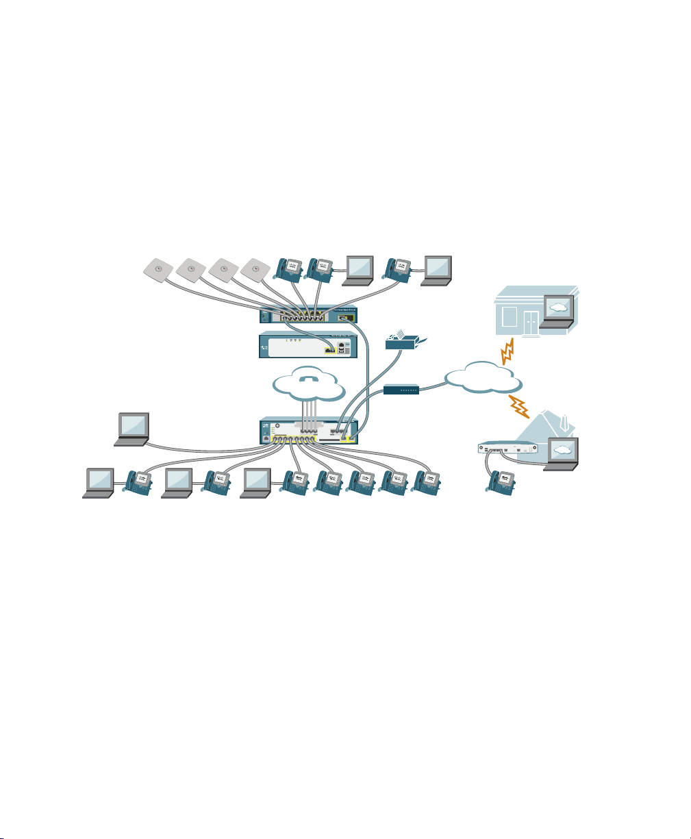
The Cisco Smart Business Communications System is shown in Figure 1.
Figure 1 Cisco Smart Business Communications System
Cisco 521
Wireless Express
Access Points
Cisco
Configuration
Assistant/
Cisco Monitor
Manager
Catalyst Express 520 Switch
Cisco 526 Wireless Express
Mobility Contoller
Cisco Unified
Communications 500 Series
PSTN
Fax
12
Internet
DSL/Cable
Modem
Cisco 870 Series
Router
Cisco
Monitor
Director
Partner
Site
Teleworker
Site
201608
After performing an initial setup, you configure the WLC526 and its controller-based AP521s using
the CCA.
Related Documentation
This guide assumes that you are installing your WLC526 in the Cisco Smart Business Communications
System. The following documents provide information about system components and include
configuration procedures:
Cisco Smart Business Communications System Setup—This document, referred to as the “Smart Doc” in some
•
documents, contains instructions for installing, configuring, and monitoring the Cisco Smart Business
Communications System. You should use this document to configure all the components of the smart business
system.
4
Page 5

• Cisco Unified Communications 500 Series for Small Business Getting Started Guide—Provides basic
installation and setup instructions for the Cisco Unified 500 Series Platform (hereafter referred to as the
UC500).
• Getting Started Guide for the Catalyst Express 520 Switches—Provides basic installation and setup instructions
for the Cisco Catalyst Express 520 switch (hereafter referred to as the CE520).
• User Guide for the Catalyst Express 520 Switches—Provides advanced configuration information for the
CE520 switch.
• Cisco Configuration Assistant Quick Start Guide—Contains basic installation and configuration instructions
for the Cisco Configuration Assistant (CCA).
• Quick Start Guide: Cisco 521 Wireless Express Access Point—Contains mounting instructions for the AP521.
These documents are available on cisco.com. Follow these steps to obtain these documents on cisco.com:
Step 1 Browse to http://www.cisco.com
Step 2 Click Support. A drop-down window appears.
Step 3 In the drop-down window, Click Documentation. The Support Documentation page appears.
Step 4 In the Product and Support section, click Wireless. The Support Wireless page appears.
Step 5 Scroll down to the Cisco Mobility Express section.
Step 6 Select the link for the wireless express component you need. The Introduction page for that
component appears.
Step 7 Download the appropriate document.
3 Unpacking and Preparing the Controller for Operation
Follow these steps to unpack the controller and prepare it for operation:
Step 1 Open the shipping container and carefully remove the contents.
Step 2 Return all packing materials to the shipping container and save it.
Step 3 Ensure that all items listed in the “Package Contents” section are included in the shipment. If
any item is damaged or missing, notify your authorized Cisco sales representative.
5
Page 6
Package Contents
Each WLC526 controller package contains the following items:
• One Cisco 526 wireless LAN controller
• One power cord
• One Ethernet cable (RJ45 to RJ45)
• One Console cable (RJ45 to DB9)
• This guide
• Cisco product registration card
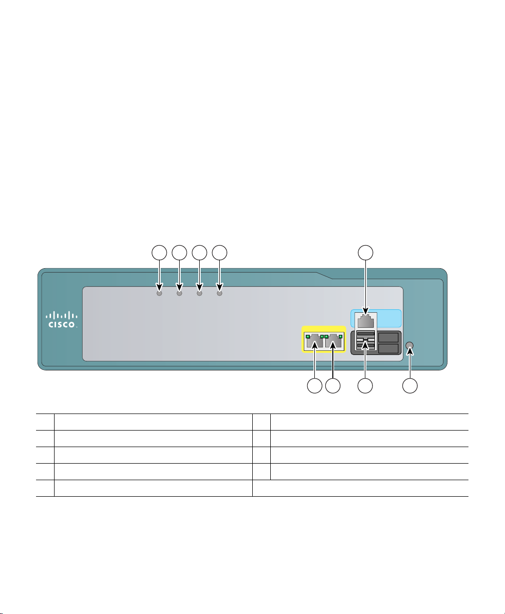
Figure 2 shows the front panel of the WLC526 and identifies its components.
Figure 2 WLC526 Front Panel
91 2 3 4
AP LED
1
Alarm LED
2
Status LED
3
Power LED
4
Distribution port 2
5
AP ALARM STATUS POWER
5 6 7 8
Distribution port 1
6
USB ports (not used)
7
Reset button
8
Console port
9
Cisco 520
12
Series Wireless LAN Controller
CONSOLE
1
2
230871
6
Page 7

Choosing a Physical Location
You can install the controller on a horizontal or vertical surface. The controller’s bottom plate has two
keyhole slots that permit you to mount it on a vertical surface, such as a wall. For maximum reliability,
mount the controller while following these guidelines:
• Make sure you can reach the controller and all cables attached to it.
• Make sure that water or excessive moisture cannot get into the controller.
• Make sure that airflow through the controller is not obstructed. Leave at least 4 in. (10 cm) clear
on both sides of the controller.
• Verify that the ambient temperature remains between 32 to 104° F (0 to 40° C).
• Make sure that the controller is installed in the same building and is within 328 ft. (100 m) of
equipment connected to the 10/100BASE-T ports.
• Make sure that the power cord can reach a 100 to 240 VAC grounded electrical outlet.
Moving a Controller
If you are staging your system in a lab environment or moving a controller to new location with a
different network domain, you must remember to change the IP addresses for the AP Management,
Management, and all Dynamic interfaces to the customer’s final IP addresses before moving the
controller to the customer site or to a new location. The IP addresses can only be changed using the
controller GUI interface. The console port interface can not be used to change IP addresses.
Using the Startup Wizard
When you power up the WLC526 you must prepare it for operation on your network by using the
controller’s GUI-based startup wizard. You will need to gather some information about your network
before you start the wizard. Table 1 lists the information you need to enter into the startup wizard.
7
Page 8

Table 1 Startup Wizard Information
Wizard Setting Action
System Name The name you want to assign to the controller.
You can enter up to 32 ASCII characters.
Administrative user name and password The administrative username and password to be
assigned to this controller. You can enter up to 24
ASCII characters for each.
The default administrative username and
password are both admin and admin.
Management Interface VLAN Identifier The VLAN identifier of the management
interface (a valid VLAN identifier or 0 for an
untagged VLAN).
The VLAN identifier should be set to match the
switch interface configuration.
Management Interface IP Address The management interface is the default interface
for in-band management of the controller and
connectivity to services such as AAA servers.
You can access the controller’s GUI interface
using this address.
Management Interface Netmask Enter the IP address of the management interface
netmask.
Management Interface Default Router Enter the IP address of the default router.
Management Interface Port Number Enter the port number of the access point
manager interface. The default is 1.
Primary DHCP Server IP Address The management interface DHCP server IP
address. The default is 192.168.1.1.
Secondary DHCP server IP Address The IP address of the a secondary DHCP server.
The default is 0.0.0.0.
LWAPP Transport Mode The default is Layer 3.
RF Mobility Domain Name The name of the mobility group/RF group to
which you want the controller to belong.
The default is default.
8
Page 9

Table 1 Startup Wizard Information (continued)
Wizard Setting Action
Configured Country Code The country for which the controller is
configured. This setting is not changeable in the
startup wizard.
Regulatory Domain The domain in which the controller is to be
operated. Selection is made using the appropriate
domain checkbox.
AP Manager Interface Name The name assigned to the access point manager
interface. This setting is not changeable in the
startup wizard.
AP Manager VLAN identifier The VLAN identifier of the access point
management interface (a valid VLAN identifier
or 0 for an untagged VLAN).
AP Manager IP address The IP address of the access point manager
Interface.
AP Manager netmask The Netmask of the access point manager
Interface.
AP Manager Gateway IP address The IP address of the access point manager
interface.
AP Manager port number The port number of the access point manager
interface. The default is 1.
AP Manager Primary DHCP Server IP address The IP address of the access point manager
primary DHCP server interface.
AP Manager Secondary DHCP Server The IP address of the access point manager
secondary DHCP server interface.
Virtual Interface Name The name of the controller’s virtual interface.
This setting is not changeable in the startup
wizard. The default is virtual.
Virtual Interface IP address The IP address for the virtual interface.
Virtual Interface DNS Host Name The name of the controller’s virtual interface
DNS host.
WLAN ID The identification number of the wireless LAN on
which this controller resides. This setting cannot
be changed in the startup wizard. The default is 1.
Profile Name The profile name of the wireless LAN.
9
Page 10

Table 1 Startup Wizard Information (continued)
Wizard Setting Action
WLAN SSID The network name, or service set identifier
(SSID). This is the default SSID that the access
points use when they join a controller.
RADIUS Server IP Address The IP address of the RADIUS server if one is
available and you intend to use it. If you are using
a RADIUS server, the following fields must be
completed:
• Shared secret format (ASCII or HEX)
• Shared secret
• Confirm shared secret
• RADIUS server port (default port is 1812)
• Server status (enabled or disabled)
802.11b Network Status Check the checkbox to enable or disable the
802.11b radio network. The default is Enabled.
802.11g Network Status Check the checkbox to enable or disable the
802.11g radio network. The default is enabled.
Auto-RF Check the checkbox to enable or disable
automatic radio resource management. The
default is enabled.
10
Page 11
To use the controller’s startup wizard, you will need an Ethernet-capable PC running Windows XP and
an Ethernet cable. The controller’s default IP address is 192.168.1.1. Make sure your PC is configured
to receive an IP address automatically. When the controller boots for the first time, it becomes a DHCP
server and automatically assigns an IP address to your PC.
Note The default IP address and DHCP server are only available when the controller is configured
with factory default values.
Follow these steps to start the wizard:
Step 1 Connect the Ethernet cable to the Ethernet port on your PC.
Step 2 Connect the other end of the Ethernet cable to data port 1 on the WLC526.
Step 3 Plug the supplied, country-specific power cord into the AC power receptical on the back of
the controller.
Step 4 Plug plug the other end of the AC power cord into a grounded 100–240 VAC, 50/60 Hz
electrical outlet.
Step 5 Power up the WLC526. The controller begins its boot process, which takes approximately 3
minutes.
Step 6 Open your web browser and browse to IP address 192.168.1.1. A network password screen
appears.
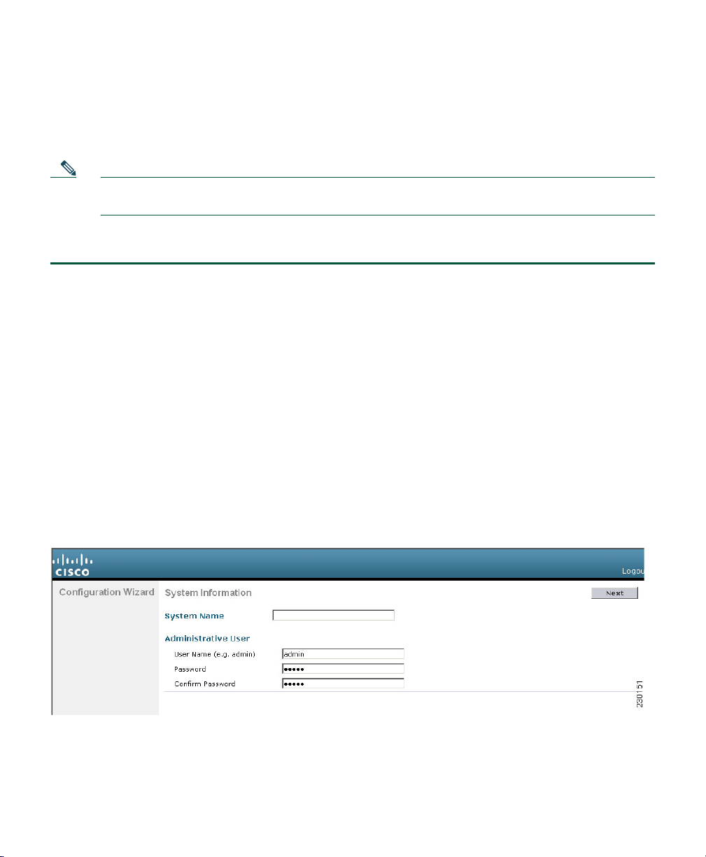
Step 7 Enter admin for both the username and password (default value). The System Information
screen appears (See Figure 3).
Figure 3 WLC526 System Information Screen
Step 8 For security reasons, you should change the username and password to non-default values.
Enter a system name, a new username, and a new password in the respective fields.
11
Page 12
Step 9 Confirm your password in the Confirm Password field.
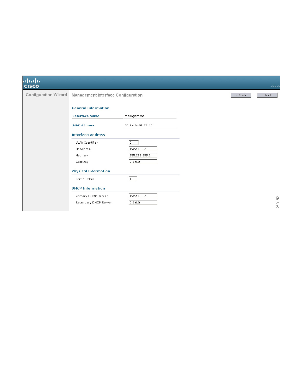
Step 10 Click Next. The Management Interface Configuration screen appears (See Figure 4).
Figure 4 Management Interface Configuration Screen
Step 11 Enter the management interface IP address, network mask, and gateway IP address
information.
Step 12 Enter the port number (1 or 2) for your management interface.
Step 13 Optional: enter DHCP server IP address information (default 192.168.1.1 for primary DHCP
server).
Step 14 Click Next and the Miscellaneous Configuration screen appears (see Figure 5).
12
Page 13
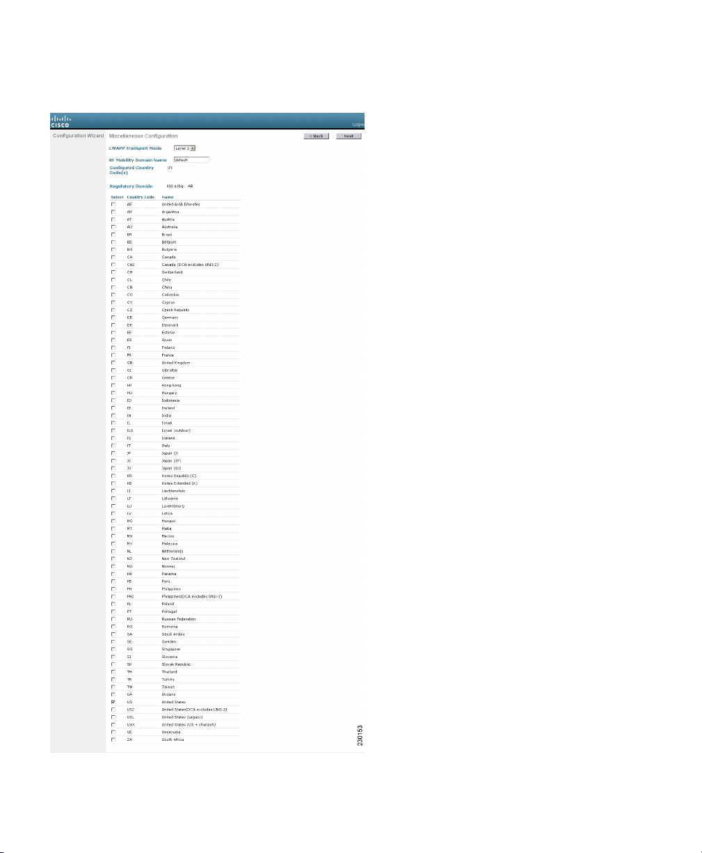
Figure 5 Miscellaneous Configuration Screen
13
Page 14
Step 15 Optional, choose the LWAPP Transport Mode (Layer 3 default).
Step 16 Enter the RF mobility domain name.
Step 17 Check your country code.
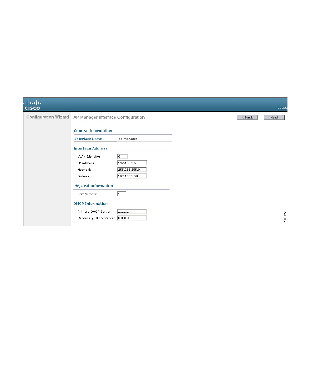
Step 18 Click Next and the AP Manager Interface Configuration screen appears (see Figure 6).
Figure 6 AP Manager Interface Configuration Screen
Step 19 Enter the AP manager interface IP address information.
Step 20 Enter the gateway IP address.
Step 21 Enter the port number (1 or 2) for the AP Manager Interface.
Step 22 Enter the primary and secondary DHCP server IP addresses.
Step 23 Click Next and the Virtual Configuration screen appears (see Figure 6).
14
Page 15

Figure 7 Virtual Interface Configuration Screen
Step 24 Enter the virtual interface IP address. Default is 1.1.1.1 (a non-valid IP address).
Step 25 Enter the DNS host name.
Step 26 Click Next and the WLAN Configuration screen appears (see Figure 8).
Figure 8 WLAN Configuration Screen
Step 27 Enter the profile name for your wireless network.
Step 28 Enter the service service identifier (SSID) for your wireless network.
Step 29 Click Next and a pop-up message appears indicating the default security settings that are
applied to the wireless LAN. You can change the default security options after the setup
wizard is complete.
Step 30 Click OK and the Radius Server Configuration screen appears (see Figure 9).
15
Page 16

Figure 9 RADIUS Server Configuration Screen
Step 31 Optional, enter the RADIUS server configuration information.
Step 32 If you have configured RADIUS information, click Apply, otherwise click Skip and the 802.11
Configuration screen appears (see Figure 10).
Figure 10 802.11 Configuration Screen
Step 33 To enable wireless network status, check the appropriate network types that you want to
support.
Step 34 Optional: check Auto RF to turn on radio resource management.
Note Radio resource management requires three or more access points in order to operate.
Step 35 Click Next and the Configuration Wizard Completed screen appears (see Figure 11).
16
Page 17

Figure 11 Configuration Wizard Completed Screen
Step 36 Click the Save And Reboot button to save your configuration.
Note Click the Back button to return to previous screens if you need to change any part of
your configuration.
Your WLC526 is ready to connect to an SBCS compatible switch.
4 Connecting to an SBCS Compatible Switch
Follow the instructions given in the Cisco Smart Business Communications System Setup document to
connect your controller to an SBCS compatible switch, such as the switch. Refer to the “Related
Documentation” section on page 4 for instructions on how to obtain this document.
Note A maximum of two controllers can be configured to the switch.
5 Connecting Access Points
Follow the instructions given in the Cisco Smart Business Communications System Setup document to
attach up to six access points to the controller. Refer to the “Related Documentation” section on
page 4 for instructions on how to obtain this document.
17
Page 18

6 Mounting the WLC526 Controller
The WLC526 controller can be mounted as follows:
• On a horizontal or vertical surface such as a desktop or shelf.
• Face up or down on a vertical surface such as a wall.
Mounting on a Desktop or Shelf
The WLC526 has four rubber pads on the bottom to help prevent it from sliding on or scratching the
surface of your desktop or shelf.
Mounting on a Vertical Surface
The bottom plate of the controller has two keyhole slots to facilitate mounting on a vertical surface
(see Figure 12).
18
Page 19

Figure 12 WLC526 Bottom Plate
7.0 (INCHES)
1
2
Rubber pads
1
AC power receptacle
2
Note You must provide the hardware necessary to mount the controller securely and safely.
3
Keyhole slots
3
1
230872
19
Page 20

Caution When vertically mounting your controller, you must mount the controller with its front
panel facing down (towards the floor) unless you are using a security lock cable. If you
are using a security lock cable, you can mount the front panel facing up (towards the
ceiling) or facing down. You must not mount the controller with the side facing down.
These restrictions are due to UL safety regulations.
The following steps describe how to mount the controller on a drywall vertical surface. Your procedure
may vary depending on the material of your vertical surface. You will need the following tools and
fasteners:
• Two #8 drywall anchors
• Two #8 x 1-in. pan head screws
• An appropriate screw driver
• A drill and 3/16-in. (4.7 mm) bit
• A ruler and marking pencil
Step 1 Determine the position on the surface where you will mount your WLC526.
Step 2 Mark the position of the center of the keyhole slots on the surface. Verify that the marks are
7-in. (17.8 cm) apart.
Step 3 Drill a 3/16-in. (4.7 mm) hole at the places you marked on the surface.
Step 4 Insert the drywall anchors into the holes.
Step 5 Insert and start two #8 x 1-in. pan head screws into the anchors.
Step 6 Use a screwdriver to drive the screws into the anchors until the heads are protruding
approximately 1/4-in. (6.4 mm) from the anchors.
Step 7 Align the keyhole slots on the controller bottom plate over the screws. Make sure the front
panel is facing down if you are not using the security lock feature.
Step 8 Gently push the controller in and down until it is secured by the narrow end of the keyhole
slot. You may have to adjust the pan head screws in order to obtain a secure fit.
20
Page 21

7 In Case of Difficulty
Checking the Controller LEDs
If your controller is not working properly, check the LEDs on the front panel of the unit. You can use
the LED indications to quickly assess the unit’s status.
Table 2 Controller LED Signals
AP
Message Type
Start BIOS Off Off Amber BIOS starting—2 to 3 seconds.
Boot ROMMON Off Off Slowly
Boot kernel Off Off Green Kernel booting—approximately 25 seconds.
Boot Switchdriver Off Off Blinking
Controller
operational
Reset button pressed Off Green Amber Reset button pressed for 10 seconds or more.
Access points
associated
Access point image
download
LED
Off Off Green Controller operational and configuration not set
Green Green Green Controller operational and configuration reset to
Off Off Amber Reset button pressed for 3 seconds but less than 10
Green Off Green One or more access points are associated to the
Off Off Green No access points are associated to the controller.
Blinking
amber
Blinking
green
and off
Alarm
LED
Off Green Access point image is being downloaded.
Off Green Access point image download is complete.
Status
LED Meaning
Boot ROMMON starting—3 to 4 seconds.
blinking
green
Boot switchdriver starting—approximately 20
green
seconds.
to default values.
factory defaults. Connect PC to Ethernet port 1 to
start configuring the controller.
Controller clears the configuration and reboots.
seconds. Controller reboots.
controller.
21
Page 22

AP
Message Type
Controller image
upgrade
Controller crash Off Amber Green The controller software has crashed.
Controller boot error Off Off Amber The controller has experienced a boot error.
LED
Off Off Blinking
Off Off Green Controller image upgrade is complete.
Alarm
LED
Status
LED Meaning
Controller image is being upgraded.
amber
Using the Reset Button
The Reset button on the controller’s front panel becomes active after the controller boots. You can use
the Reset button to reset power or to reset the configuration to factory defaults.
Resetting Controller Power
Follow these steps to reset power to the controller using the Reset button:
Step 1 Place a straightened paper clip into the Reset button hole.
Step 2 While observing the controller LEDs, gently push and hold the Reset button with the paper
clip.
Step 3 When the Status LED turn amber, release the Reset button by removing the paper clip.
The controller configuration settings are not reset. If you have configured the controller, it
reboots and loads the active configuration. If you have not configured the controller, the
startup wizard GUI appears.
Resetting the Controller to Factory Defaults
Follow these steps to reset the controller to factory defaults using the Reset button:
Step 1 Place a straightened paper clip into the Reset button hole.
Step 2 While observing the controller LEDs, gently push and hold the Reset button with the paper
clip.
22
Page 23

Step 3 When the Alarm LED turns green, release the Reset button by removing the paper clip.
Step 4 The controller power cycles and reboots. The controller configuration settings are reset to
factory defaults and the startup wizard GUI appears.
Invalid or Unknown Controller IP Address
If your controller contains an invalid or unknown IP address, you will be unable to access the
controller GUI and your management software also will be unable to communicate with the controller.
This problem can occur when someone moves a controller to a different network domain without
changing the controller IP addresses or accidentally configures an invalid IP address.
You can correct this problem by resetting the controller to factory defaults using the reset button and
then reconfiguring the controller using the startup wizard GUI.
8 Cisco One Year Limited Hardware Warranty Terms
There are special terms applicable to your hardware warranty and various services that you can use
during the warranty period. Your formal Warranty Statement, including the warranties and license
agreements applicable to Cisco software, is available on Cisco.com. Follow these steps to access and
download the Cisco Information Packet and your warranty and license agreements from Cisco.com.
1. Launch your browser, and go to this URL:
http://www.cisco.com/univercd/cc/td/doc/es_inpck/cetrans.htm
The Warranties and License Agreements page appears.
2. To r e ad th e Cisco Information Packet, follow these steps:
a. Click the Information Packet Number field, and make sure that the part number
78-5235-03B0 is highlighted.
b. Select the language in which you would like to read the document.
c. Click Go.
The Cisco Limited Warranty and Software License page from the Information Packet appears.
d. Read the document online, or click the PDF icon to download and print the document in
Adobe Portable Document Format (PDF).
Note You must have Adobe Acrobat Reader to view and print PDF files. You can download
the reader from Adobe’s website: http://www.adobe.com
23
Page 24

3. To read translated and localized warranty information about your product, follow these steps:
a. Enter this part number in the Warranty Document Number field:
78-10747-01C0
b. Select the language in which you would like to read the document.
c. Click Go.
The Cisco warranty page appears.
d. Review the document online, or click the PDF icon to download and print the document in
Adobe Portable Document Format (PDF).
You can also contact the Cisco service and support website for assistance:
http://www.cisco.com/public/Support_root.shtml.
Duration of Hardware Warranty
One year.
Replacement, Repair, or Refund Policy for Hardware
Cisco or its service center will use commercially reasonable efforts to ship a replacement part within
ten (10) working days after receipt of a Return Materials Authorization (RMA) request. Actual
delivery times can vary, depending on the customer location.
Cisco reserves the right to refund the purchase price as its exclusive warranty remedy.
To Receive a Return Materials Authorization (RMA) Number
Contact the company from whom you purchased the product. If you purchased the product directly
from Cisco, contact your Cisco Sales and Service Representative.
Complete the information below, and keep it for reference:
Company product purchased from
Company telephone number
Product model number
Product serial number
Maintenance contract number
24
Page 25

9 Translated Warnings
Statement 1071—Warning Definition
Warning
Waarschuwing
Varoitus
IMPORTANT SAFETY INSTRUCTIONS
This warning symbol means danger. You are in a situation that could cause
bodily injury. Before you work on any equipment, be aware of the hazards
involved with electrical circuitry and be familiar with standard practices for
preventing accidents. Use the statement number provided at the end of each
warning to locate its translation in the translated safety warnings that
accompanied this device.
SAVE THESE INSTRUCTIONS
BELANGRIJKE VEILIGHEIDSINSTRUCTIES
Dit waarschuwingssymbool betekent gevaar. U verkeert in een situatie die
lichamelijk letsel kan veroorzaken. Voordat u aan enige apparatuur gaat
werken, dient u zich bewust te zijn van de bij elektrische schakelingen
betrokken risico's en dient u op de hoogte te zijn van de standaard praktijken
om ongelukken te voorkomen. Gebruik het nummer van de verklaring
onderaan de waarschuwing als u een vertaling van de waarschuwing die bij
het apparaat wordt geleverd, wilt raadplegen.
BEWAAR DEZE INSTRUCTIES
TÄRKEITÄ TURVALLISUUSOHJEITA
Tämä varoitusmerkki merkitsee vaaraa. Tilanne voi aiheuttaa ruumiillisia
vammoja. Ennen kuin käsittelet laitteistoa, huomioi sähköpiirien
käsittelemiseen liittyvät riskit ja tutustu onnettomuuksien yleisiin
ehkäisytapoihin. Turvallisuusvaroitusten käännökset löytyvät laitteen
mukana toimitettujen käännettyjen turvallisuusvaroitusten joukosta
varoitusten lopussa näkyvien lausuntonumeroiden avulla.
Statement 1071
SÄILYTÄ NÄMÄ OHJEET
25
Page 26

Attention
Warnung
Avvertenza
IMPORTANTES INFORMATIONS DE SÉCURITÉ
Ce symbole d'avertissement indique un danger. Vous vous trouvez dans une
situation pouvant entraîner des blessures ou des dommages corporels. Avant
de travailler sur un équipement, soyez conscient des dangers liés aux circuits
électriques et familiarisez-vous avec les procédures couramment utilisées
pour éviter les accidents. Pour prendre connaissance des traductions des
avertissements figurant dans les consignes de sécurité traduites qui
accompagnent cet appareil, référez-vous au numéro de l'instruction situé à la
fin de chaque avertissement.
CONSERVEZ CES INFORMATIONS
WICHTIGE SICHERHEITSHINWEISE
Dieses Warnsymbol bedeutet Gefahr. Sie befinden sich in einer Situation, die
zu Verletzungen führen kann. Machen Sie sich vor der Arbeit mit Geräten mit
den Gefahren elektrischer Schaltungen und den üblichen Verfahren zur
Vorbeugung vor Unfällen vertraut. Suchen Sie mit der am Ende jeder Warnung
angegebenen Anweisungsnummer nach der jeweiligen Übersetzung in den
übersetzten Sicherheitshinweisen, die zusammen mit diesem Gerät
ausgeliefert wurden.
BEWAHREN SIE DIESE HINWEISE GUT AUF.
IMPORTANTI ISTRUZIONI SULLA SICUREZZA
26
Questo simbolo di avvertenza indica un pericolo. La situazione potrebbe
causare infortuni alle persone. Prima di intervenire su qualsiasi
apparecchiatura, occorre essere al corrente dei pericoli relativi ai circuiti
elettrici e conoscere le procedure standard per la prevenzione di incidenti.
Utilizzare il numero di istruzione presente alla fine di ciascuna avvertenza per
individuare le traduzioni delle avvertenze riportate in questo documento.
CONSERVARE QUESTE ISTRUZIONI
Page 27

Advarsel
Aviso
¡Advertencia!
VIKTIGE SIKKERHETSINSTRUKSJONER
Dette advarselssymbolet betyr fare. Du er i en situasjon som kan føre til skade
på person. Før du begynner å arbeide med noe av utstyret, må du være
oppmerksom på farene forbundet med elektriske kretser, og kjenne til
standardprosedyrer for å forhindre ulykker. Bruk nummeret i slutten av hver
advarsel for å finne oversettelsen i de oversatte sikkerhetsadvarslene som
fulgte med denne enheten.
TA VARE PÅ DISSE INSTRUKSJONENE
INSTRUÇÕES IMPORTANTES DE SEGURANÇA
Este símbolo de aviso significa perigo. Você está em uma situação que poderá
ser causadora de lesões corporais. Antes de iniciar a utilização de qualquer
equipamento, tenha conhecimento dos perigos envolvidos no manuseio de
circuitos elétricos e familiarize-se com as práticas habituais de prevenção de
acidentes. Utilize o número da instrução fornecido ao final de cada aviso para
localizar sua tradução nos avisos de segurança traduzidos que acompanham
este dispositivo.
GUARDE ESTAS INSTRUÇÕES
INSTRUCCIONES IMPORTANTES DE SEGURIDAD
Este símbolo de aviso indica peligro. Existe riesgo para su integridad física.
Antes de manipular cualquier equipo, considere los riesgos de la corriente
eléctrica y familiarícese con los procedimientos estándar de prevención de
accidentes. Al final de cada advertencia encontrará el número que le ayudará
a encontrar el texto traducido en el apartado de traducciones que acompaña
a este dispositivo.
GUARDE ESTAS INSTRUCCIONES
27
Page 28

Varning!
VIKTIGA SÄKERHETSANVISNINGAR
Denna varningssignal signalerar fara. Du befinner dig i en situation som kan
leda till personskada. Innan du utför arbete på någon utrustning måste du vara
medveten om farorna med elkretsar och känna till vanliga förfaranden för att
förebygga olyckor. Använd det nummer som finns i slutet av varje varning för
att hitta dess översättning i de översatta säkerhetsvarningar som medföljer
denna anordning.
SPARA DESSA ANVISNINGAR
28
Page 29

30 31 32 33
29
Page 30

Page 31

Page 32

Page 33

Statement 1015—Battery Handling
Warning
Waarschuwing
Varoitus
Attention
Warnung
Avvertenza
There is the danger of explosion if the battery is replaced incorrectly. Replace
the battery only with the same or equivalent type recommended by the
manufacturer. Dispose of used batteries according to the manufacturer’s
instructions.
Er is ontploffingsgevaar als de batterij verkeerd vervangen wordt. Vervang de
batterij slechts met hetzelfde of een equivalent type dat door de fabrikant
aanbevolen is. Gebruikte batterijen dienen overeenkomstig
fabrieksvoorschriften weggeworpen te worden.
Räjähdyksen vaara, jos akku on vaihdettu väärään akkuun. Käytä
vaihtamiseen ainoastaan saman- tai vastaavantyyppistä akkua, joka on
valmistajan suosittelema. Hävitä käytetyt akut valmistajan ohjeiden mukaan.
Danger d'explosion si la pile n'est pas remplacée correctement. Ne la
remplacer que par une pile de type semblable ou équivalent, recommandée
par le fabricant. Jeter les piles usagées conformément aux instructions du
fabricant.
Bei Einsetzen einer falschen Batterie besteht Explosionsgefahr. Ersetzen Sie
die Batterie nur durch den gleichen oder vom Hersteller empfohlenen
Batterietyp. Entsorgen Sie die benutzten Batterien nach den Anweisungen des
Herstellers.
Pericolo di esplosione se la batteria non è installata correttamente. Sostituire
solo con una di tipo uguale o equivalente, consigliata dal produttore.
Eliminare le batterie usate secondo le istruzioni del produttore.
Statement 1015
Advarsel
Aviso
Det kan være fare for eksplosjon hvis batteriet skiftes på feil måte. Skift kun
med samme eller tilsvarende type som er anbefalt av produsenten. Kasser
brukte batterier i henhold til produsentens instruksjoner.
Existe perigo de explosão se a bateria for substituída incorrectamente.
Substitua a bateria por uma bateria igual ou de um tipo equivalente
recomendado pelo fabricante. Destrua as baterias usadas conforme as
instruções do fabricante.
Page 34

¡Advertencia!
Varning!
Existe peligro de explosión si la batería se reemplaza de manera incorrecta.
Reemplazar la batería exclusivamente con el mismo tipo o el equivalente
recomendado por el fabricante. Desechar las baterías gastadas según las
instrucciones del fabricante.
Explosionsfara vid felaktigt batteribyte. Ersätt endast batteriet med samma
batterityp som rekommenderas av tillverkaren eller motsvarande. Följ
tillverkarens anvisningar vid kassering av använda batterier.
34
Page 35

Statement 1024—Ground Conductor
Warning
Waarschuwing
Varoitus
Attention
Warnung
This equipment must be grounded. Never defeat the ground conductor or
operate the equipment in the absence of a suitably installed ground conductor.
Contact the appropriate electrical inspection authority or an electrician if you
are uncertain that suitable grounding is available.
Deze apparatuur dient geaard te zijn. De aardingsleiding mag nooit buiten
werking worden gesteld en de apparatuur mag nooit bediend worden zonder
dat er een op de juiste wijze geïnstalleerde aardingsleiding aanwezig is.
Neem contact op met de bevoegde instantie voor elektrische inspecties of met
een elektricien als u er niet zeker van bent dat er voor passende aarding
gezorgd is.
Laitteiden on oltava maadoitettuja. Älä koskaan ohita maajohdinta tai käytä
laitteita ilman oikein asennettua maajohdinta. Ota yhteys
sähkötarkastusviranomaiseen tai sähköasentajaan, jos olet epävarma
maadoituksen sopivuudesta.
Cet équipement doit être mis à la masse. Ne jamais rendre inopérant le
conducteur de masse ni utiliser l'équipement sans un conducteur de masse
adéquatement installé. En cas de doute sur la mise à la masse appropriée
disponible, s'adresser à l'organisme responsable de la sécurité électrique ou
à un électricien.
Dieses Gerät muss geerdet sein. Auf keinen Fall den Erdungsleiter unwirksam
machen oder das Gerät ohne einen sachgerecht installierten Erdungsleiter
verwenden. Wenn Sie sich nicht sicher sind, ob eine sachgerechte Erdung
vorhanden ist, wenden Sie sich an die zuständige Inspektionsbehörde oder
einen Elektriker.
Statement 1024
Avvertenza
Questa apparecchiatura deve essere dotata di messa a terra. Non escludere
mai il conduttore di protezione né usare l'apparecchiatura in assenza di un
conduttore di protezione installato in modo corretto. Se non si è certi della
disponibilità di un adeguato collegamento di messa a terra, richiedere un
controllo elettrico presso le autorità competenti o rivolgersi a un elettricista.
35
Page 36

Advarsel
Aviso
¡Advertencia!
Varning!
Dette utstyret må jordes. Omgå aldri jordingslederen og bruk aldri utstyret
uten riktig montert jordingsleder. Ta kontakt med fagfolk innen elektrisk
inspeksjon eller med en elektriker hvis du er usikker på om det finnes
velegnet jordning.
Este equipamento deve ser aterrado. Nunca anule o fio terra nem opere o
equipamento sem um aterramento adequadamente instalado. Em caso de
dúvida com relação ao sistema de aterramento disponível, entre em contato
com os serviços locais de inspeção elétrica ou um eletricista qualificado.
Este equipo debe estar conectado a tierra. No inhabilite el conductor de tierra
ni haga funcionar el equipo si no hay un conductor de tierra instalado
correctamente. Póngase en contacto con la autoridad correspondiente de
inspección eléctrica o con un electricista si no está seguro de que haya una
conexión a tierra adecuada.
Denna utrustning måste jordas. Koppla aldrig från jordledningen och använd
aldrig utrustningen utan en på lämpligt sätt installerad jordledning. Om det
föreligger osäkerhet huruvida lämplig jordning finns skall elektrisk
besiktningsauktoritet eller elektriker kontaktas.
36
Page 37

38
37
Page 38

Statement 1040—Product Disposal
Warning
Waarschuwing
Varoitus
Attention
Warnung
Ultimate disposal of this product should be handled according to all national
laws and regulations.
Het uiteindelijke wegruimen van dit product dient te geschieden in
overeenstemming met alle nationale wetten en reglementen.
Tämä tuote on hävitettävä kansallisten lakien ja määräysten mukaisesti.
La mise au rebut ou le recyclage de ce produit sont généralement soumis à des
lois et/ou directives de respect de l'environnement. Renseignez-vous auprès
de l'organisme compétent.
Die Entsorgung dieses Produkts sollte gemäß allen Bestimmungen und
Gesetzen des Landes erfolgen.
Statement 1040
Page 39

Avvertenza
Advarsel
Aviso
¡Advertencia!
Varning!
Lo smaltimento di questo prodotto deve essere eseguito secondo le leggi e
regolazioni locali.
Endelig kassering av dette produktet skal være i henhold til alle relevante
nasjonale lover og bestemmelser.
Deitar fora este produto em conformidade com todas as leis e regulamentos
nacionais.
Al deshacerse por completo de este producto debe seguir todas las leyes y
reglamentos nacionales.
Vid deponering hanteras produkten enligt gällande lagar och bestämmelser.
39
Page 40

Statement 371—Power Cable and AC Adapter - Japan
40
Page 41

42 43
41
Page 42

Page 43

Page 44

C
C
C
F
M
T
A
b
Americas Headquarters
Cisco Systems, Inc.
170 West Tasman Drive
San Jose, CA 95134-1706
USA
www.cisco.com
Tel: 408 526-4000
800 553-NETS (6387)
Fax: 408 527-0883
Asia Pacific Headquarters
Cisco Systems, Inc.
168 Robinson Road
#28-01 Capital Tower
Singapore 068912
www.cisco.com
Tel: +65 6317 7777
Fax: +65 6317 7799
Europe Headquarters
Cisco Systems International BV
Haarlerbergpark
Haarlerbergweg 13-19
1101 CH Amsterdam
The Netherlands
www-europe.cisco.com
Tel: 31 0 800 020 0791
Fax: 31 0 20 357 1100
Cisco has more than 200 offices worldwide. Addresses, phone numbers, and fax numbers are listed on the
Cisco Website at www.cisco.com/go/offices.
CVP, the Cisco logo, and Welcome to the Human Network are trademarks of Cisco Systems, Inc.; Changing the Way We Work, Live, Play, and Learn is a service mark of
isco Systems, Inc.; and Access Registrar, Aironet, Catalyst, CCDA, CCDP, CCIE, CCIP, CCNA, CCNP, CCSP, Cisco, the Cisco Certified Internetwork Expet logo, Cisco IOS,
isco Press, Cisco Systems, Cisco Systems Capital, the Cisco Systems logo, Cisco Unity, Enterprise/Solver, EtherChannel, EtherFast, EtherSwitch, Fast Step, Follow Me Browsing,
ormShare, GigaDrive, HomeLink, Internet Quotient, IOS, iPhone, IP/TV, iQ Expertise, the iQ logo, iQ Net Readiness Scorecard, iQuick Study, LightStream, Linksys, MeetingPlace,
GX, Networkers, Networking Academy, Network Registrar, PIX, ProConnect, ScriptShare, SMARTnet, StackWise, The Fastest Way to Increase Your Internet Quotient, and
ransPath are registered trademarks of Cisco Systems, Inc. and/or its affiliates in the United States and certain other countries.
ll other trademarks mentioned in this document or Website are the property of their respective owners. The use of the word partner does not imply a partnership relationship
etween Cisco and any other company. (0711R)
© 2008 Cisco Systems, Inc. All rights reserved.
Printed in the USA on recycled paper containing 10% postconsumer waste.
78-18091-03
DOC-78-18091=
 Loading...