

Page 1

User Guide for the
Catalyst Express 520 Switches
Cisco IOS Release Number 12.2(37)EX
September 2007
Americas Headquarters
Cisco Systems, Inc.
170 West Tasman Drive
San Jose, CA 95134-1706
USA
http://www.cisco.com
Tel: 408 526-4000
800 553-NETS (6387)
Fax: 408 527-0883
Text Part Number: OL-12761-02
Page 2

THE SPECIFICATIONS AND INFORMATION REGARDING THE PRODUCTS IN THIS MANUAL ARE SUBJECT TO CHANGE WITHOUT
NOTICE. ALL STATEMENTS, INFORMATION, AND RECOMMENDATIONS IN THIS MANUAL ARE BELIEVED TO BE ACCURATE BUT
ARE PRESENTED WITHOUT WARRANTY OF ANY KIND, EXPRESS OR IMPLIED. USERS MUST TAKE FULL RESPONSIBILITY FOR
THEIR APPLICATION OF ANY PRODUCTS.
THE SOFTWARE LICENSE AND LIMITED WARRANTY FOR THE ACCOMPANYING PRODUCT ARE SET FORTH IN THE
INFORMATION PACKET THAT SHIPPED WITH THE PRODUCT AND ARE INCORPORATED HEREIN BY THIS REFERENCE. IF YOU
ARE UNABLE TO LOCATE THE SOFTWARE LICENSE OR LIMITED WARRANTY, CONTACT YOUR CISCO REPRESENTATIVE FOR A
COPY.
The following information is for FCC compliance of Class A devices: This equipment has been tested and found to comply with the limits for a Class
A digital device, pursuant to part 15 of the FCC rules. These limits are designed to provide reasonable protection against harmful interference when
the equipment is operated in a commercial environment. This equipment generates, uses, and can radiate radio-frequency energy and, if not installed
and used in accordance with the instruction manual, may cause harmful interference to radio communications. Operation of this equipment in a
residential area is likely to cause harmful interference, in which case users will be required to correct the interference at their own expense.
The following information is for FCC compliance of Class B devices: The equipment described in this manual generates and may radiate
radio-frequency energy. If it is not installed in accordance with Cisco’s installation instructions, it may cause interference with radio and television
reception. This equipment has been tested and found to comply with the limits for a Class B digital device in accordance with the specifications in
part 15 of the FCC rules. These specifications are designed to provide reasonable protection against such interference in a residential installation.
However, there is no guarantee that interference will not occur in a particular installation.
Modifying the equipment without Cisco’s written authorization may result in the equipment no longer complying with FCC requirements for Class
A or Class B digital devices. In that event, your right to use the equipment may be limited by FCC regulations, and you may be required to correct
any interference to radio or television communications at your own expense.
You can determine whether your equipment is causing interference by turning it off. If the interference stops, it was probably caused by the Cisco
equipment or one of its peripheral devices. If the equipment causes interference to radio or television reception, try to correct the interference by
using one or more of the following measures:
• Turn the television or radio antenna until the interference stops.
• Move the equipment to one side or the other of the television or radio.
• Move the equipment farther away from the television or radio.
• Plug the equipment into an outlet that is on a different circuit from the television or radio. (That is, make certain the equipment and the television
or radio are on circuits controlled by different circuit breakers or fuses.)
Modifications to this product not authorized by Cisco Systems, Inc. could void the FCC approval and negate your authority to operate the product.
The Cisco implementation of TCP header compression is an adaptation of a program developed by the University of California, Berkeley (UCB) as
part of UCB’s public domain version of the UNIX operating system. All rights reserved. Copyright © 1981, Regents of the University of California.
NOTWITHSTANDING ANY OTHER WARRANTY HEREIN, ALL DOCUMENT FILES AND SOFTWARE OF THESE SUPPLIERS ARE
PROVIDED “AS IS” WITH ALL FAULTS. CISCO AND THE ABOVE-NAMED SUPPLIERS DISCLAIM ALL WARRANTIES, EXPRESSED
OR IMPLIED, INCLUDING, WITHOUT LIMITATION, THOSE OF MERCHANTABILITY, FITNESS FOR A PARTICULAR PURPOSE AND
NONINFRINGEMENT OR ARISING FROM A COURSE OF DEALING, USAGE, OR TRADE PRACTICE.
IN NO EVENT SHALL CISCO OR ITS SUPPLIERS BE LIABLE FOR ANY INDIRECT, SPECIAL, CONSEQUENTIAL, OR INCIDENTAL
DAMAGES, INCLUDING, WITHOUT LIMITATION, LOST PROFITS OR LOSS OR DAMAGE TO DATA ARISING OUT OF THE USE OR
INABILITY TO USE THIS MANUAL, EVEN IF CISCO OR ITS SUPPLIERS HAVE BEEN ADVISED OF THE POSSIBILITY OF SUCH
DAMAGES.
CCVP, the Cisco logo, and the Cisco Square Bridge logo are trademarks of Cisco Systems, Inc.; Changing the Way We Work, Live, Play, and Learn
is a service mark of Cisco Systems, Inc.; and Access Registrar, Aironet, BPX, Catalyst, CCDA, CCDP, CCIE, CCIP, CCNA, CCNP, CCSP, Cisco,
the Cisco Certified Inte rnetwork Expert logo, Cisco IOS, Cisco Press, Cisco Systems, Cisco Systems Capital, the Cisco Systems logo, Cisco Unity,
Enterprise/Solver, EtherChannel, EtherFast, EtherSwitch, Fast Step, Follow Me Browsing, FormShare, GigaDrive, HomeLink, Internet Quotient,
IOS, iPhone, IP/TV, iQ Expertise, the iQ logo, iQ Net Readiness Scorecard, iQuick Study, LightStream, Linksys, MeetingPlace, MGX, Networking
Academy, Network Registrar, Packet, PIX, ProConnect, ScriptShare, SMARTnet, StackWise, The Fastest Way to Increase Your Internet Quotient,
and TransPath are registered trademarks of Cisco Systems, Inc. and/or its affiliates in the United States and certain other countries.
Page 3

All other trademarks mentioned in this document or Website are the property of their respective owners. The use of the word partner does not imply
a partnership relationship between Cisco and any other company. (0705R)
Any Internet Protocol (IP) addresses used in this document are not intended to be actual addresses. Any examples, command display output, and
figures included in the document are shown for illustrative purposes only. Any use of actual IP addresses in illustrative content is unintentional and
coincidental.
User Guide for the Catalyst Express 520 Switches
© 2007 Cisco Systems, Inc. All rights reserved.
Page 4

Page 5

Using This Guide ix
How This Guide Is Organized ix
Switch Documentation Set xi
Related Documentation xi
CONTENTS
CHAPTER
CHAPTER
1 Introduction 1-1
Overview 1-2
Hardware Features 1-6
Software Features 1-10
Device Manager 1-10
Cisco Configuration Assistant 1-13
Box Contents 1-14
Supported Hardware 1-14
Hardware Requirements 1-15
Software Requirements 1-15
2 Setting Up the Switch 2-1
Warnings 2-2
Set Up the Switch (Existing Network) 2-2
Set Up the Switch (No Network) 2-7
Secured Sessions with the Switch 2-12
When You Are Done 2-12
OL-12761-02
User Guide for the Catalyst Express 520 Switches
v
Page 6

Contents
CHAPTER
CHAPTER
3 Installing the Switch 3-1
Warnings 3-2
Installation Guidelines 3-5
Install the Switch On a Desk or Shelf 3-7
Install the Switch in a Rack 3-8
Install the Switch on a Wall 3-11
When You Are Done 3-12
4 Connecting to the Switch 4-1
Warnings 4-2
Cabling Guidelines 4-2
Connect to an Ethernet Port 4-3
Install an SFP Module into an SFP Module Slot 4-4
Remove an SFP Module from an SFP Module Slot 4-5
Connect to a Fiber-Optic SFP Module Port 4-6
Connect to a Dual-Purpose Port 4-7
When You Are Done 4-8
CHAPTER
vi
5 Changing the Switch Network Settings 5-1
Change the Switch IP Information 5-2
Change Optional Administrative Settings 5-2
When You Are Done 5-3
User Guide for the Catalyst Express 520 Switches
OL-12761-02
Page 7

Contents
CHAPTER
CHAPTER
6 Monitoring the Switch 6-1
Review the Front Panel View and the LEDs 6-2
Review the Dashboard 6-6
Review the Port Status 6-7
Review the Port Statistics 6-7
Review the Alert Log 6-8
When You Are Done 6-9
7 Troubleshooting the Switch 7-1
Troubleshoot IP Address Problems 7-2
IP Address Is Not Received from DHCP Server 7-2
Switch Has Wrong IP Address 7-2
Troubleshoot Displaying of the Device Manager 7-3
Device Manager Does Not Display 7-3
Device Manager Is Not Operating Properly 7-4
Device Manager Has A Slow Response Time 7-4
Device Manager Is Not Accessible Through the Network 7-4
OL-12761-02
Troubleshoot Connections to the Switch 7-5
Switch and Other Device Are Not Communicating 7-5
Cisco IP Phones Continually Disconnect 7-5
Access Direct Managed Mode 7-6
Restart the Switch 7-7
Reset the Switch 7-8
Recover a Username or Password 7-9
Recover the Switch Software 7-10
Troubleshoot a Failed Software Upgrade 7-11
If You Need Further Help 7-11
User Guide for the Catalyst Express 520 Switches
vii
Page 8

Contents
APPENDIX
APPENDIX
A Reference A-1
Technical Specifications A-2
Location of the Switch Serial Number A-4
Connector Specifications A-5
10/100 and 10/100/1000 Ports A-5
SFP Module Ports A-8
Dual-Purpose Ports A-9
Cabling Guidelines A-10
Ethernet Port Connections A-10
Small Form-Factor Pluggable Module Port Connections A-10
Cable and Adapter Specifications A-13
Two Twisted-Pair Cable Pinouts A-13
Four Twisted-Pair Cable Pinouts for 1000BASE-T Ports A-14
Crossover Cable A-15
B Cisco Support Resources B-1
Cisco Small and Medium-Sized Business (SMB) Solutions B-2
Cisco Networking Professionals Connection B-2
I
NDEX
viii
Obtaining Documentation, Obtaining Support, and Security Guidelines B-2
User Guide for the Catalyst Express 520 Switches
OL-12761-02
Page 9

Using This Guide
This guide is for those who will install or use the switch. It covers the topics to
help you learn about the switch and how to effectively use it.
Although extensive networking knowledge is not necessary, we recommend
familiarity with LAN switch fundamentals. The Cisco Press General Networking
Resources website has links to documents that provide internetworking
overviews.
http://www.cisco.com/web/about/ac123/ac220/about_cisco_general_networking
_resources.html
How This Guide Is Organized
This guide is organized in this way:
Chapter 1, “Introduction”
Chapter 2, “Setting Up the
Switch”
Chapter 3, “Installing the
Switch”
Chapter 4, “Connecting to
the Switch”
OL-12761-02
This chapter describes the software and hardware features and benefits so
that you can decide how to use the switch to meet your network objectives.
This chapter provides the recommendations, the guidelines, and the
procedures for setting up the switch for the first time. It also includes
procedures on how to display the device manager interface through a
secured mode.
This chapter provides the recommendations, the guidelines, and the
procedures for installing the switch.
This chapter provides the recommendations, the guidelines, and the
procedures for connecting devices to the switch.
User Guide for the Catalyst Express 520 Switches
ix
Page 10

How This Guide Is Organized
Using This Guide
Chapter 5, “Changing the
Switch Network Settings”
Chapter 6, “Monitoring the
Switch”
Chapter 7, “Troubleshooting
the Switch”
Appendix A, “Reference”
Appendix B, “Cisco Support
Resources”
This document uses the following conventions and symbols for notes, cautions,
and warnings. Translations of the warning statements in this document appear in
the Regulatory Compliance and Safety Information for the Catalyst Express 520
Switches document.
Note Means reader take note. Notes contain helpful suggestions or references to
materials not contained in this manual.
This chapter describes the basic IP address settings and administrative
switch settings that you can modify from the switch device manager.
Use this chapter with the procedures in the device manager online help.
This chapter describes the device manager features that you can use to
monitor the status and the performance of the switch.
Use this chapter with the procedures in the device manager online help.
This chapter provides basic troubleshooting advice to help you resolve
basic switch and network problems.
This appendix has the switch technical specifications, including the switch
serial number location, cabling guidelines, and connector specifications.
This appendix describes the Cisco resources where you can learn more
about networking and the switch, can obtain Cisco documentation, and can
access Cisco technical support.
Caution Means reader be careful. In this situation, you might do something that could
result in equipment damage or loss of data.
Warning
User Guide for the Catalyst Express 520 Switches
x
This warning symbol means danger. You are in a situation that could cause
bodily injury. Before you work on any equipment, be aware of the hazards
involved with electrical circuitry and be familiar with standard practices for
preventing accidents. Use the statement number provided at the end of each
warning to locate its translation in the translated safety warnings that
accompanied this device. Statement 1071
OL-12761-02
Page 11

Using This Guide
Switch Documentation Set
These documents provide complete information about the switch and are
available from this Cisco.com site:
http://www.cisco.com/en/US/products/ps7238/tsd_products_support_series_ho
me.html
These documents are also available on the Cisco Smart Business Communications
System Software and Documentation CD-ROM that ships with the switch.
You can order printed copies of documents with a DOC-xxxxxx= number from
the Cisco.com sites and from the telephone numbers listed in the URL referenced
in the “Obtaining Documentation, Obtaining Support, and Security Guidelines”
section on page B-2.
• Release Notes for the Catalyst Express 520 Switches (not orderable but
available on Cisco.com)
• Getting Started Guide for the Catalyst Express 520 Switches (order number
DOC-7818063=)
• User Guide for the Catalyst Express 520 Switches (not orderable but available
on Cisco.com)
Switch Documentation Set
• Device manager online help (available on the switch)
• Regulatory Compliance and Safety Information for the Catalyst Express 520
Switches (not orderable but available on Cisco.com)
• Cisco Limited Lifetime Hardware Warranty Terms for the Catalyst
Express 520 Switches (not orderable but available on Cisco.com)
Related Documentation
For information about related products, see these documents:
• Cisco Small Form-Factor Pluggable Modules Installation Notes (order
number DOC-7815160=)
• Cisco RPS 675 Redundant Power System Hardware Installation Guide (order
number DOC-7815201=)
• Release Notes for Cisco Configuration Assistant (not orderable but available
on Cisco.com)
OL-12761-02
User Guide for the Catalyst Express 520 Switches
xi
Page 12

Switch Documentation Set
Using This Guide
• Getting Started with Cisco Configuration Assistant (not orderable but
available on Cisco.com)
• Cisco Configuration Assistant online help (available from the application).
• Cisco Unified Communications 500 Series for Small Business Getting Started
Guide (not orderable but available on Cisco.com)
xii
User Guide for the Catalyst Express 520 Switches
OL-12761-02
Page 13

CHAPTER
1
Introduction
Read this chapter to familiarize yourself with the features, benefits, and
capabilities of the Catalyst Express 520 switches.
Chapter Topics
• Overview, page 1-2
• Hardware Features, page 1-6
• Software Features, page 1-10
• Box Contents, page 1-14
• Supported Hardware, page 1-14
• Hardware Requirements, page 1-15
• Software Requirements, page 1-15
OL-12761-02
User Guide for the Catalyst Express 520 Switches
1-1
Page 14

Chapter 1 Introduction
Overview
Overview
The Catalyst Express 520 switches provide network services that can support the
data, voice, and mobile network demands of small and medium-sized businesses.
The services ensure transmission quality and reliability for data and voice traffic.
They also provide security to protect against network attacks.
The Catalyst Express 520 switches are designed to be
• Smart—Each switch port is applied with a specific Cisco-recommended
configuration (referred to as a Smartports port role) to optimize the switch
connections and to ensure security, transmission quality, and reliability for
traffic from the switch ports.
• Simple—Setup of the switch can be through a connection to an existing
network with a Dynamic Host Configuration Protocol (DHCP) server, such
as a Cisco Unified Communications 500 Series, or through the Express Setup
feature of the switch device manager GUI.
• Secure—The switch supports three levels of business-optimized network
security. Traffic between the switch and the network management
applications is also encrypted through the Secure Sockets Layer (SSL)
protocol.
You can simply install the switch and allow it to operate without any further
management intervention. Use device and network management tools to take
advantage of the software features and to optimize your use of the switch. With
these tools, you can quickly and easily set up, customize, monitor, and
troubleshoot the switch.
OL-12761-02
Table 1-1 describes the Catalyst Express 520 switches, and Figure 1-1 and
Figure 1-2 show the switches in network examples.
User Guide for the Catalyst Express 520 Switches
1-2
Page 15

Chapter 1 Introduction
Overview
Table 1-1 Catalyst Express 520 Switches
Catalyst Express 520-8PC-K9
This switch provides Power over Ethernet (PoE) to Cisco IP phones and wireless access points. Because
of its compact size, it can be deployed outside the traditional wiring-closet environment, such as in
office workspaces and classrooms. It has
• 8 10/100 PoE ports for desktop, printer, IP phone, server, and wireless access-point connectivity
• 1 dual-purpose port (one 10/100/1000BASE-T copper port and one small form-factor pluggable
[SFP] module slot) for switch, router, or server connectivity
Catalyst Express 520-24TT-K9
This switch provides standard connections to network users. It has
• 24 10/100 (Fast Ethernet) ports for desktop and printer connectivity
• 2 10/100/1000 (Gigabit Ethernet) ports for switch, router, or server connectivity
Catalyst Express 520-24LC-K9
This switch provides standard connections to network users and provides connections to PoE devices.
It has
• 20 10/100 ports for desktop and printer connectivity
• 4 10/100 PoE ports for IP phone and wireless access point connectivity
• 2 dual-purpose ports for switch, router, or server connectivity
Catalyst Express 520-24PC-K9
This switch provides standard connections to network users and provides connections to PoE devices.
It has
• 24 10/100 PoE ports for desktop, printer, IP phone, and wireless access point connectivity
• 2 dual-purpose ports for switch, router, or server connectivity
Catalyst Express 520G-24TC-K9
This switch provides high-speed connections to servers and switches. It has
• 24 10/100/1000 ports for high-speed, desktop connectivity
• 2 dual-purpose ports for server aggregation or for switch, router, or server connectivity
User Guide for the Catalyst Express 520 Switches
OL-12761-02
1-3
Page 16
Chapter 1 Introduction
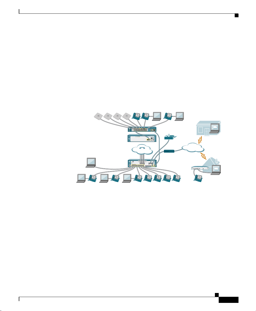
Cisco Smart Business Communications System Network Example
The Catalyst Express 520 switches are the recommended companion switches to
the Cisco Unified Communications 500 Series. These devices are part of the
Cisco Smart Business Communications System solution (Figure 1-1).
The Cisco Smart Business Communications System is a unified communications
solution for small businesses that provides voice, data, video, security, and
wireless capabilities while integrating with existing desktop applications such as
calendar, e-mail, and Customer Relationship Management (CRM).
Figure 1-1 Cisco Smart Business Communications System Solution
Overview
Cisco 521
Wireless Express
Access Points
Catalyst Express 520 Switch
Cisco 526 Wireless Express
Mobility Contoller
Cisco
Configuration
Assistant/
Cisco Monitor
Manager
Communications 500 Series
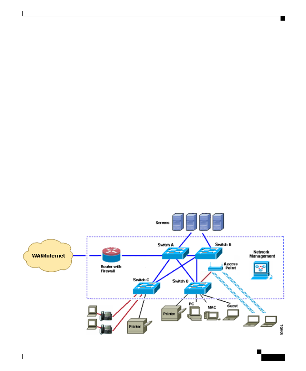
Catalyst Express Switch Network Example
Figure 1-2 is an example of how to use the different Catalyst Express switches to
enable communication between network users and to provide them access to
network resources.
Any of the Catalyst Express 520 switches can be Switches A, B, C, and D in this
network. To take full advantage of the different models of the Catalyst
Express 520 switch platform, use the one that is designed for the type of
connections that you require.
• Switches A and B: Use the Catalyst Express 520G-24TC-K9 model. It has
the most Gigabit Ethernet ports, and it is best suited to providing 1000-Mb/s
connections between switches and to servers. Multiple connections between
the switches ensure that users maintain network access if any of the switches
becomes overused or unavailable.
Cisco Unified
PSTN
Cisco
Monitor
Director
Partner
Fax
12
Internet
DSL/Cable
Modem
Cisco 870 Series
Router
Site
Teleworker
Site
201608
OL-12761-02
User Guide for the Catalyst Express 520 Switches
1-4
Page 17
Chapter 1 Introduction
Overview
• Switches C and D: Use the Catalyst Express 520-24TT-K9 or the Catalyst
Express 520G-24TC-K9 model to provide high-speed (up to 100 Mb/s and
1000 Mb/s, respectively) connections to network users.
You can also use the Catalyst Express 520-24LC-K9 or the Catalyst
Express 520-24PC-K9 model to connect Cisco prestandard and IEEE
802.3af-compliant powered devices, such as IP phones and access points, to
your network. PoE connections from these switches can provide both network
access and power for up to 4 or up to 24 PoE devices, respectively.
If the switch detects that there is no power on the circuit, the PoE ports
provide up to 15.4 W of power to attached PoE devices. You can place PoE
devices where power outlets are not available or are not convenient and thus
avoid cabling costs.
You can manage the network onsite or remotely through the Cisco Configuration
Assistant network management application. Through Cisco Configuration
Assistant, you can also optimize the switches. For example, you can configure
VLANs that give priority to voice traffic over regular data traffic from the desktop
devices attached to the IP phones. Other VLANs can provide different types of
network users—wired employees, wireless (or mobile) employees, and wired and
wireless company visitors—with different access levels to the company network.
OL-12761-02
Figure 1-2 Catalyst Express Switch Network Example
User Guide for the Catalyst Express 520 Switches
1-5
Page 18

Chapter 1 Introduction
SYSTEM
ALERT
PoE
ADMIN
RP
S
Hardware Features
Figure 1-3 and the list that follows describe the switch hardware features and the
benefits that they provide. For hardware installation information, see Chapter 3,
“Installing the Switch.”
Figure 1-3 Hardware Features
Hardware Features
1AC power
connector
2 RPS
connector
12
152
3
1
2
3
4
5
6
1
7
8
9
1
0
1
1
1
2
1
3
1
4
1
5
1
6
1
1
1
7
1
1
3
8
1
9
2
0
2
1
2
2
2
2
P
O
W
E
R
O
V
E
R
E
T
H
E
R
N
E
T
1
2
11
3
2
4
2
3
1
4
Catalyst Express 520
S
e
r
i
e
2
4
1
s
S
Y
S
T
E
M
A
L
E
R
T
2
P
o
E
R
P
S
A
D
M
I
N
4
10
9
6
7
8
202199
The internal power supply is an autoranging unit that supports input voltages
between 100 and 240 VAC. Use the supplied AC power cord to connect the AC
power connector to an AC power outlet.
Depending on the Catalyst Express 520 model, a Cisco RPS 675 can be
connected to the switch. The RPS is a redundant power system that automatically
senses when the internal power supply of a connected device fails and provides
power to prevent the loss of network traffic. For complete information about the
RPS, see the Cisco RPS 675 Redundant Power System Hardware Installation
Guide on Cisco.com.
Warning
Attach only the Cisco RPS (model PWR675-AC-RPS-N1=) to the RPS
receptacle.
Statement 100C
3 Security slot The security slots are on the left and right side panels. You can install an optional
cable lock, such as the type that is used to secure a laptop computer, to secure
either or both sides of the switch.
OL-12761-02
User Guide for the Catalyst Express 520 Switches
1-6
Page 19

Chapter 1 Introduction
Hardware Features
4 SYSTEM LED The SYSTEM LED shows the status of the switch (system).
Solid green Switch is healthy.
Blinking green Switch is running power-on self-test (POST). POST is a series
of tests that runs automatically to ensure that the switch
functions properly. It might take several minutes for the
switch to complete POST.
Solid amber Switch is faulty, is rebooting, or is in recovery.
5ALERT LED The ALERT LED shows the presence of a switch problem.
When the switch detects a problem on one or more ports, the Alert LED turns
amber. The Alert LED stays amber until the Alert Log is cleared. For more
information about the Alert LED and Alert Log, see Table 6-1 and the “Review
the Alert Log” section on page 6-8.
Off (dark) No switch problem is detected.
Solid amber A switch problem is detected.
6PoE LED The PoE LED shows the status of PoE being provided to the ports.
This LED is available on switches that have PoE ports.
Off (dark) PoE to the ports is off.
Solid green One or more ports is receiving PoE.
Blinking amber One or more ports is not receiving PoE because of a fault.
7 RPS LED The RPS LED shows the status of a connected redundant power system (RPS).
This LED is available on switches that have an RPS connector.
Off (dark) RPS is off or is not properly connected.
Solid green RPS is connected and is ready to provide back-up power.
Blinking green RPS is connected but is unavailable because it is providing
power to another device.
Solid amber RPS is in standby mode or is in a fault condition.
Blinking amber Switch internal power supply has failed, and the RPS is
providing power to the switch.
OL-12761-02
User Guide for the Catalyst Express 520 Switches
1-7
Page 20

Chapter 1 Introduction
Hardware Features
8ADMIN LEDThe ADMIN LED shows the management mode in which the switch is operating.
Off (dark) Switch is configured with an IP address.
Blinking green Switch is in the initial setup mode, or the switch is in direct
managed mode. For information about this mode, see the
“Device Manager Is Not Accessible Through the Network”
section on page 7-4.
9 ADMIN button The ADMIN button is used to manage the switch through a direct connection to
your PC or laptop and is used to start the recovery on the switch.
10 Uplink ports Depending on the Catalyst Express 520 model, the uplink ports can be
dual-purpose ports or 10/100/1000 ports. For information about 10/100/1000
ports, see Downlink ports.
The dual-purpose port can be used as either a 10/100/1000 port or as an SFP
module port. However, both cannot be active at the same time. If both ports are
connected, the SFP module port has priority. You cannot change this priority
setting.
The SFP module slot supports Gigabit Ethernet SFP modules to establish
fiber-optic and 1000BASE-T uplink connections. It supports the modules listed
in the “Supported Hardware” section on page 1-14.
11 Downlink
ports
Depending on the Catalyst Express 520 model, the downlink ports can be 10/100
PoE ports, 10/100 ports, or 10/100/1000 ports.
You can set these ports for speed and duplex autonegotiation, in compliance with
IEEE 802.3ab, to optimize port bandwidth.
If the connected device also supports autonegotiation, the switch port negotiates
the best connection (the fastest line speed that both devices support and
full-duplex transmission if the attached device supports it) and configures itself
accordingly. The default setting is autonegotiate.
The ports also have the automatic-medium-dependent interface crossover
(auto-MDIX) capability to automatically detect the required cable connection
type (straight-through or crossover) and to configure the connection
appropriately.
1-8
User Guide for the Catalyst Express 520 Switches
OL-12761-02
Page 21

Chapter 1 Introduction
Hardware Features
The PoE ports provide up to 15.4 W of power to connected Cisco prestandard
and IEEE 802.3af-compliant powered devices if the switch detects that there is
no power on the circuit. On a per-port basis, through the Cisco Configuration
Assistant, you can control whether the PoE port automatically provides power
when a powered device is connected. By default, the setting is Auto.
Note On the Catalyst Express 520-24LC-K9 switch, ports 1 to 4 are PoE ports.
Use the Cisco Configuration Assistant to change the port settings.
12 Port LEDs The port LEDs show port status, port duplex mode, port speed, and PoE status.
By default, the port LEDs show port status.
Use the Cisco Configuration Assistant to change and to monitor the port settings.
Note To display the port duplex mode, the port speed, and the PoE status from
the port LEDs, you must use the View list from the device manager. See
Table 6-2 and the device manager online help for information about the
View list.
Port Status
Off (dark) No link.
Solid green Link is up, but there is no activity on the link.
Blinking green Link has activity.
OL-12761-02
During direct managed mode, the port with the blinking green
LED is the selected management port to which to connect your
PC or laptop.
Blinking green
Link is faulty.
and amber
Blinking amber Port has a Smartports configuration mismatch.
Solid amber Port is faulty or is disabled due to an error condition.
User Guide for the Catalyst Express 520 Switches
1-9
Page 22

Software Features
Software Features
The switch software features are accessible from these management interfaces:
• Device Manager, page 1-10
• Cisco Configuration Assistant, page 1-13
A subset of the basic software features are accessible through the device manager.
All software features are accessible through the Cisco Configuration Assistant.
Device Manager
The device manager is a graphical device management tool for basic setup,
monitoring, and troubleshooting of individual switches.
The device manager displays real-time views of switch configuration and
performance. It simplifies configuration tasks with features such as Express Setup
for quickly setting up the switch. It uses graphical, color-coded displays, such as
the Front Panel view, graphs, and animated indicators to simplify monitoring
tasks. It provides alert tools to help you to identify and to solve networking
problems.
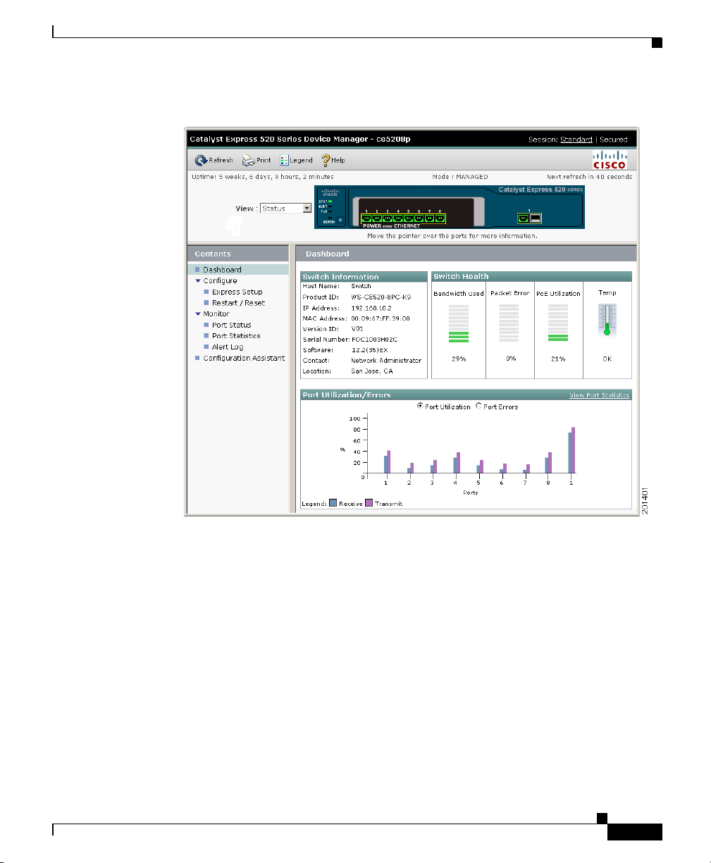
You can display the device manager (Figure 1-4) from anywhere in your network
through a web browser such as Microsoft Internet Explorer. For information on
how to display the device manager, see Chapter 2, “Setting Up the Switch.”
Chapter 1 Introduction
1-10
Table 1-2 lists the software features accessible through the device manager.
Complete details about the device manager and the procedures for using the
device manager windows are available from the device manager online help.
User Guide for the Catalyst Express 520 Switches
OL-12761-02
Page 23
Chapter 1 Introduction
Software Features
Figure 1-4 Device Manager Interface
OL-12761-02
User Guide for the Catalyst Express 520 Switches
1-11
Page 24

Chapter 1 Introduction
Software Features
Table 1-2 Software Features Accessible through the Device Manager
Express Setup
• Initial setup requires only IP information for the first-time switch configuration.
• Quick IP address updates if you move the switch to a different network.
• Date and time settings automatically synchronized between the switch and your PC or laptop.
• Dynamic Host Configuration Protocol (DHCP) automatically assigns the switch an IP address, a
default gateway, and a subnet mask from a DHCP server.
Monitoring
• ALERT LED notifies that one or more problems were detected on the switch.
• Alert Log lists all problems detected on the switch, including a timestamp of the most recent
detection of each problem.
• Graphical Front Panel view of the switch LEDs and a Dashboard, which displays gauges and
graphs that show the switch and the port status, the port utilization, and the port error percentages.
Depending on the switch, the Dashboard displays an animated indicator that shows the switch
temperature or the internal fan status.
• Port status and statistics tables and graphs display port operating status and the statistics for data
being received and sent on each port.
• Smartport status display the port roles assigned to the switch ports.
Security
• Secure Socket Layer (SSL) protocol authenticates and encrypts communications to the switch
device manager GUI.
User Guide for the Catalyst Express 520 Switches
1-12
OL-12761-02
Page 25

Chapter 1 Introduction
Cisco Configuration Assistant
Compared to the switch device manager, the Cisco Configuration Assistant offers
an enhanced set of features for configuring, monitoring, and troubleshooting the
devices in your network.
The Cisco Configuration Assistant discovers all devices in the network and can
configure all supported routers, switches, and wireless access points and
controllers as well as Cisco Unified Communications call-routing and voice-mail
systems. After the network is deployed, you also can use Cisco Configuration
Assistant to generate status reports, to synchronize passwords, and to upgrade
software across all of your Cisco network devices.
Some general Cisco Configuration Assistant features include:
• Centralized, common services—such as software upgrades, configuration
management, inventory reports, network events, alerts, and password and
configuration synchronization—for Cisco switches, routers, access points,
and voice appliances in the network
• Centralized network monitoring using two views of all connected devices in
the network: a physical view (Front Panel image) and a logical view (network
Topology image) of different network devices
• Drag-and-drop software upgrade for multiple devices, including backup and
restoration of device configuration files
• Security configuration for all the Cisco access points in the network
• Authenticated and encrypted communications between the Cisco
Configuration Assistant client and each connected network device
• Simplified troubleshooting through an Events Notification Advisor (which
identifies problems and suggests resolutions related to misconfiguration such
as Smartports or duplex-mode mismatch) and through a Link Diagnostic
Report (which identifies problems and suggests resolutions related to
connectivity such as port-speed mismatch and faulty cabling)
The Cisco Configuration Assistant is available in a number of languages.
Software Features
OL-12761-02
You can download the Cisco Configuration Assistant to your PC or laptop from
this Cisco.com site:
http://www.cisco.com/go/configassist
Complete details about the Cisco Configuration Assistant features and the
procedures for using the application are available from the Cisco Configuration
Assistant documentation and the online help.
User Guide for the Catalyst Express 520 Switches
1-13
Page 26
Box Contents
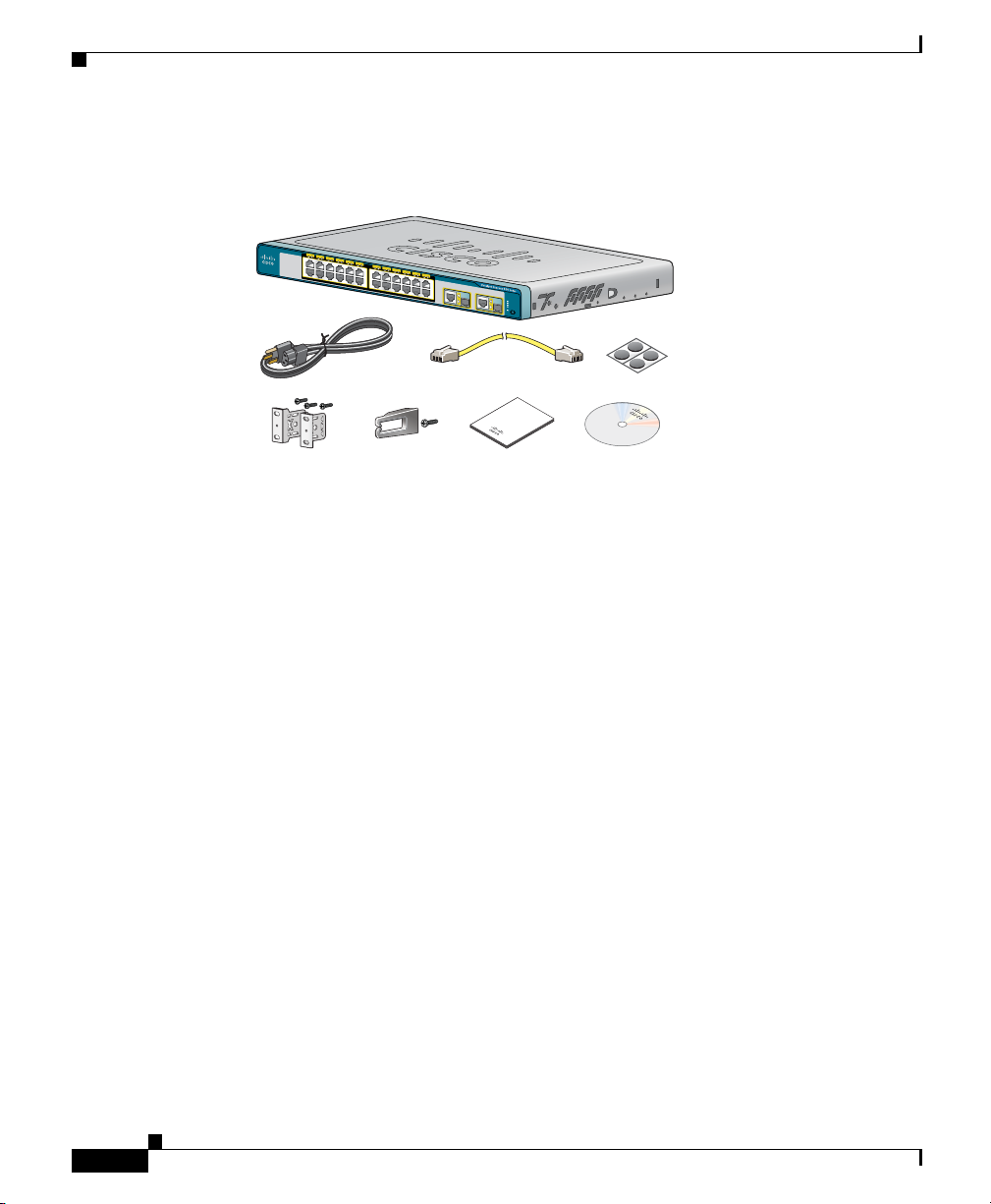
Box Contents
Verify that you have received the items shown here. If any item is missing or
damaged, contact your Cisco representative or reseller for instructions.
The model shown is a Catalyst Express 520-24PC-K9 switch. Your switch might
look slightly different.
The Catalyst Express 520-8PC-K9 switch does not ship with a rack-mount
bracket kit. You can order the kit (part number RCKMNT-19-CMPCT=) from
Cisco.
Chapter 1 Introduction
1
2
3
4
5
1
X
6
7
8
9
1
0
1
1
1
2
1
3
1
4
1
5
1
6
1
1
X
1
7
1
1
3
8
X
1
9
2
0
2
1
2
2
2
2
X
P
O
W
E
R
O
V
E
R
E
TH
E
R
N
E
T
1
2
3
2
4
2
3
X
1
4
X
X
2
4
X
1
S
Y
S
T
E
M
A
L
E
R
T
2
P
o
E
R
P
S
A
D
M
I
N
D
P
o
ro
c
d
u
u
m
c
e
t
n
ta
t
io
n
P
D
r
o
o
d
c
u
u
m
c
t
e
a
n
C
n
ta
D
d
ti
o
n
202186
Supported Hardware
The Catalyst Express 520-24PC-K9 switch supports the Cisco RPS 675
(model PWR675-AC-RPS-N1=).
The switch supports Gigabit Ethernet SFP modules for fiber-optic and
1000BASE-T connections. You can use the SFP modules for Gigabit uplink
connections to other switches or routers. SFP modules are field-replaceable.
The switch support these Cisco SFP modules:
• 100BASE-BX-10D
• 100BASE-BX-10U
• 100BASE-FX-FE
• 100BASE-FX-GE
• 100BASE-LX
User Guide for the Catalyst Express 520 Switches
1-14
OL-12761-02
Page 27

Chapter 1 Introduction
• 1000BASE-LX/LH
• 1000BASE-SX
• 1000BASE-T
For more information about these SFP modules, see your Cisco SFP module
documentation on Cisco.com.
Hardware Requirements
Table 1-3 lists the minimum hardware requirements for setting up the switch and
for using the device manager.
Table 1-3 Hardware Requirements
Processor Speed 233 MHz minimum
RAM 512 MB minimum
Free Hard Drive Space 50 MB
Number of Colors 256
Resolution 1024 x 768
Font Size Small
Hardware Requirements
1 GHz recommended
1 GB recommended
Software Requirements
Table 1-4 lists the supported operating systems and browsers for setting up the
switch and for using the device manager. The device manager verifies the browser
version when starting a session to ensure that the browser is supported.
The device manager does not require a plug-in.
You should disable any pop-up blockers or proxy settings in your browser
software and any wireless clients running on your PC or laptop.
OL-12761-02
User Guide for the Catalyst Express 520 Switches
1-15
Page 28

Software Requirements
Chapter 1 Introduction
Table 1-4 Supported Operating Systems and Browsers
Operating System Microsoft Internet Explorer Mozilla Firefox
Windows 2000 6.0 and 7.0 1.5, 2.0
Windows 2003 6.0 and 7.0 1.5, 2.0
Windows Vista 6.0 and 7.0 1.5, 2.0
Windows XP 6.0 and 7.0 1.5, 2.0
1-16
User Guide for the Catalyst Express 520 Switches
OL-12761-02
Page 29

CHAPTER
2
Setting Up the Switch
The switch can operate without an IP address assigned to it. However, we
recommend setting up the switch with an IP address so that you can manage it
through the device manager and the Cisco Configuration Assistant. Otherwise,
your switch management is limited to using only the LEDs on the switch front
panel.
For best results in setting up the switch, first follow the procedures in the getting
started guide that ships with the Cisco Unified Communications 500 Series. This
document is also available on the CD-ROM that ships with the switch.
If you do not have a Cisco Unified Communications 500 Series, follow the
guidelines and procedures in this chapter.
Before You Begin
Before you set up the switch, review the information in the Release Notes for the
Catalyst Express 520 Switches on Cisco.com.
Before you power or install the switch, review the safety information the
“Warnings” section on page 2-2.
OL-12761-02
The warnings in this chapter are translated into several languages in the
Regulatory Compliance and Safety Information for the Catalyst Express 520
Switches document on Cisco.com.
Chapter Topics
• Warnings, page 2-2
• Set Up the Switch (Existing Network), page 2-2
• Set Up the Switch (No Network), page 2-7
User Guide for the Catalyst Express 520 Switches
2-1
Page 30

Warnings
Warnings
Chapter 2 Setting Up the Switch
• Secured Sessions with the Switch, page 2-12
• When You Are Done, page 2-12
These warnings are translated into several languages in the Regulatory
Compliance and Safety Information for the Catalyst Express 520 Switches
document that shipped with the switch. Review these warnings before you power
the switch.
For a complete list of warnings that apply to the switch, see the “Warnings”
section on page 3-2.
Warning
Warning
To prevent the switch from overheating, do not operate it in an area that
exceeds the maximum recommended ambient temperature of 113°F (45°C). To
prevent airflow restriction, allow at least 3 inches (7.6 cm) of clearance around
the ventilation openings.
This equipment must be grounded. Never defeat the ground conductor or
operate the equipment in the absence of a suitably installed ground conductor.
Contact the appropriate electrical inspection authority or an electrician if you
are uncertain that suitable grounding is available.
Statement 17B
Set Up the Switch (Existing Network)
Prerequisites
• This procedure requires connecting the switch to an upstream Dynamic Host
Configuration Protocol (DHCP) server. The upstream device would assign an
IP address to the switch.
• You need the hardware and software described in the “Hardware
Requirements” section on page 1-15 and the “Software Requirements”
section on page 1-15.
Statement 1024
2-2
User Guide for the Catalyst Express 520 Switches
OL-12761-02
Page 31

Chapter 2 Setting Up the Switch
• You need the Category 5 Ethernet cable that is shipped with the switch.
• You should disable any pop-up blockers or proxy settings in your browser
software and any wireless clients running on your PC or laptop.
Follow these steps:
Set Up the Switch (Existing Network)
Step 1
Step 2
Make sure that nothing is connected to the
switch.
Use the supplied switch power cable to
connect the switch to an AC power source.
Before proceeding to the next step, wait until
the SYSTEM LED stops blinking green and
becomes solid green. A solid green SYSTEM
LED means that the switch is operating
properly.
The ADMIN LED should be blinking green.
A blinking green ADMIN LED means that the
switch does not have an IP address yet.
Troubleshooting:
If the SYSTEM LED does not blink green,
does not turn solid green, or turns amber,
contact your Cisco representative or reseller.
The switch failed the power-on self-test
(POST).
S
Y
S
T
A
L
RT
1
2
P
o
E
A
D
M
I
N
3
4
5
6
7
8
C
a
t
a
l
y
s
t
E
x
p
r
POW
E
R
OV
E
R
E
T
H
E
R
N
E
T
e
s
s
5
2
0
S
e
r
i
e
s
1
191681
191682
S
Y
S
SY
T
ST
A
L
RT
1
2
P
A
o
E
L
R
T
3
4
5
Po
A
E
D
M
I
N
A
D
M
IN
6
7
8
C
a
t
a
l
y
s
t
E
x
p
r
POW
E
R
OV
E
R
E
T
H
E
R
N
E
T
e
s
s
5
2
0
S
e
r
i
e
s
1
191683
OL-12761-02
User Guide for the Catalyst Express 520 Switches
2-3
Page 32

Set Up the Switch (Existing Network)
Chapter 2 Setting Up the Switch
Step 3
Use the supplied Category 5 Ethernet cable to connect an upstream DHCP server (such as the
Cisco Unified Communications 500 Series) to the switch dual-purpose port.
Before proceeding to the next step, wait until the port LEDs on the switch and the other device
blink green. The solid green port LEDs means a successful connection between the two
devices.
The ADMIN LED should still be blinking green.
Troubleshooting:
If the port LEDs do not blink green or if either LED turns amber, make sure that you are using
the Category 5 Ethernet cable that shipped with the switch. If not, make sure that the cable
that you are using is an undamaged Category 5 Ethernet cable.
P
O
E
V
M
S
E
E
M
A
N
U
A
L
W
B
E
L
A
N
S
Y
S
T
A
L
RT
1
2
P
o
E
3
4
5
A
D
M
I
N
6
7
8
C
a
t
a
l
y
s
t
E
x
p
r
POW
E
R
OV
E
R
E
T
H
E
R
N
E
T
e
s
s
5
2
0
S
e
r
i
e
s
1
C
F
O
R
is
E
I
N
c
S
T
A
o
L
L
A
U
T
I
O
N
n
if
ie
d
5
0
0
S
e
r
ie
s
201615
2-4
User Guide for the Catalyst Express 520 Switches
OL-12761-02
Page 33

Chapter 2 Setting Up the Switch
Set Up the Switch (Existing Network)
Step 4
Verify that the ADMIN LED is off, which
means that the switch has received an IP
address from the upstream DHCP server and
that the initial setup is complete.
Username-and-password pairs prevent
unauthorized access by those who could
guess the password. We recommend that the
switch has at least one
username-and-password pair to secure access
to the device manager. The default username
is cisco. The default password is cisco.
Troubleshooting:
If the ADMIN LED continues to blink green,
it means that the switch is still not configured
with an IP address. Make sure that an
upstream device is operating as a DHCP
server.
SYST
S
Y
S
T
A
L
RT
1
2
P
o
A
E
L
R
T
3
4
5
Po
A
D
M
E
I
N
A
D
M
IN
6
7
8
C
a
t
a
l
y
s
t
E
x
p
r
PO
W
E
R
OVE
R
E
T
H
E
R
N
E
T
e
s
s
5
2
0
Se
r
ie
s
1
201616
OL-12761-02
User Guide for the Catalyst Express 520 Switches
2-5
Page 34

Set Up the Switch (Existing Network)
Chapter 2 Setting Up the Switch
Step 5
You can now manage the switch through the Cisco Configuration Assistant and the device
manager.
We strongly recommend that you download the Cisco Configuration Assistant from
Cisco.com and use it to manage the switch. You can download it from the CD-ROM that ships
with the switch or from this Cisco.com site:
http://www.cisco.com/go/configassist
You can display the device manager by following these steps:
1. Start a web browser on your PC or laptop.
2. Enter the switch IP address, username, and password in the web browser, and press
Enter. The device manager page appears.
If you do not know the switch IP address, you can display the device manager and find out
the switch IP address by following the procedure in the “Access Direct Managed Mode”
section on page 7-6.
Troubleshooting:
If the device manager does not appear, make sure that you entered the correct switch IP
address in the browser.
If you entered the correct switch IP address in the browser, make sure that the switch and your
PC or laptop are in the same network or subnetwork. For example:
• If your switch IP address is 172.20.20.85 and your PC or laptop IP address is
172.20.20.84, both devices are in the same network.
2-6
• If your switch IP address is 172.20.20.85 and your PC or laptop IP address is 10.0.0.2,
the devices are in different networks and cannot directly communicate without a router.
You must either change the switch IP address or change the PC or laptop IP address.
Tip We recommend running a secured session with the switch. See the “Secured Sessions
with the Switch” section on page 2-12 for information on how to ensure that your
management session with the switch is protected from unauthorized access.
User Guide for the Catalyst Express 520 Switches
OL-12761-02
Page 35

Chapter 2 Setting Up the Switch
Set Up the Switch (No Network)
Prerequisites
• You need the hardware and software described in the “Hardware
Requirements” section on page 1-15 and the “Software Requirements”
section on page 1-15.
• You need the Category 5 Ethernet cable that is shipped with the switch.
• You should disable any pop-up blockers or proxy settings in your browser
software and any wireless clients running on your PC or laptop.
Follow these steps:
Set Up the Switch (No Network)
Step 1
Step 2
Make sure that nothing is connected to the
switch.
Use the supplied switch power cable to
connect the switch to an AC power source.
Before proceeding to the next step, wait until
the SYSTEM LED stops blinking green and
becomes solid green. A solid green SYSTEM
LED means that the switch is operating
properly.
The ADMIN LED should be blinking green.
A blinking green ADMIN LED means that the
switch does not have an IP address yet.
Troubleshooting:
If the SYSTEM LED does not blink green, does
not turn solid green, or turns amber, contact
your Cisco representative or reseller. The switch
failed the power-on self-test (POST).
S
Y
S
T
A
L
RT
1
2
P
o
E
A
D
M
I
N
3
4
5
6
7
8
C
a
t
a
l
y
s
t
E
x
p
r
POW
E
R
OV
E
R
E
T
H
E
R
N
E
T
e
s
s
5
2
0
S
e
r
i
e
s
1
191681
191682
SYST
S
Y
S
T
A
L
RT
1
2
P
A
o
E
L
R
T
3
4
5
Po
A
E
D
M
I
N
A
D
M
IN
6
7
8
C
a
t
a
l
y
s
t
E
x
p
r
POW
E
R
OV
E
R
E
T
H
E
R
N
E
T
e
s
s
5
2
0
S
e
ri
e
s
1
191683
OL-12761-02
User Guide for the Catalyst Express 520 Switches
2-7
Page 36

Set Up the Switch (No Network)
PO
WER
O
VER
ETHERNET
1
2
Chapter 2 Setting Up the Switch
Step 3
Use the supplied Category 5 Ethernet cable to
connect your PC or laptop to any of the
downlink switch ports (such as port 1).
Before proceeding to the next step, wait until
the port LEDs on the switch and your PC or
laptop are green (either solid or blinking).
The green port LEDs means a successful
connection between the two devices.
The ADMIN LED should still be blinking
green.
Troubleshooting:
If the port LEDs are not solid green or if either
port LED turns amber, make sure that:
• You connected the Category 5 Ethernet
cable to one of the downlink switch ports
(not to an uplink port such as the
dual-purpose port).
• You are using the Category 5 Ethernet
cable that shipped with the switch. If not,
make sure that the cable that you are
using is an undamaged Category 5
Ethernet cable.
• The other device is turned on.
S
Y
S
T
A
L
R
T
1
2
P
o
E
3
4
5
A
D
M
I
N
6
7
8
C
a
t
a
l
y
s
t
E
x
p
r
POW
E
R
O
V
E
R
E
T
H
E
R
N
E
T
e
s
s
5
2
0
S
e
r
i
e
s
1
191685
User Guide for the Catalyst Express 520 Switches
2-8
OL-12761-02
Page 37

Chapter 2 Setting Up the Switch
Set Up the Switch (No Network)
Step 4
Step 5
Start a web browser session on your PC or
laptop to any URL, such as www.cisco.com.
Before proceeding to the next step, wait until
S
Y
S
T
A
L
RT
1
2
P
o
E
3
4
5
A
D
M
I
N
6
7
8
C
a
t
a
ly
s
t
E
x
p
r
PO
W
E
R
O
V
E
R
E
T
H
E
R
N
E
T
e
s
s
5
2
0
S
e
r
i
e
s
1
the Express Setup window appears.
The ADMIN LED should still be blinking
green.
Troubleshooting:
If the Express Setup window does not appear,
make sure that any pop-up blockers or proxy
settings on your browser are disabled and that
any wireless client is disabled on your PC or
laptop.
1. Enter the network setting in the Express Setup window.
The network settings enable the switch to operate with its standard default settings and
to be managed through the device manager and the Cisco Configuration Assistant. You
must apply these settings to access and to take advantage of the monitoring,
troubleshooting, and configuration features on the switch. Otherwise, your switch
management is limited to using only the LEDs on the switch front panel.
Username-and-password pairs prevent unauthorized access by those who could guess the
password. We recommend that the switch has at least one username-and-password pair to
secure access to the device manager. The default username is cisco. The default password
is cisco.
191686
If you need more information about the Express Setup fields, see the device manager online
help.
OL-12761-02
2. (Optional) Enter the optional administrative settings in the Express Setup window.
The optional administrative settings identify and synchronize the switch so that it can be
managed properly. The switch clock is automatically synchronized with the system clock
on your PC or laptop. You can manually set the system clock settings if the switch should
have different time settings.
3. Click Submit to save your changes and to complete the initial setup.
User Guide for the Catalyst Express 520 Switches
2-9
Page 38

Set Up the Switch (No Network)
Chapter 2 Setting Up the Switch
Step 6
After you click Submit, these events occur:
• The Express Setup program ends.
• The connection between the switch and
your PC or laptop ends.
• If your PC or laptop is connected to a
DHCP server, your PC or laptop loses its
IP address that was used during the initial
setup.
• Your browser session displays an error
page.
Verify that the ADMIN LED is off, which
means that the switch is configured with the
IP address that you entered in the Express
Setup window and that the initial setup is
complete.
Troubleshooting:
If the ADMIN LED continues to blink green,
it means that the switch is still not configured
with an IP address. Repeat Step 1 to Step 5.
If the problem persists:
SYST
S
Y
S
T
A
L
RT
1
2
P
o
A
E
L
R
T
3
4
5
Po
A
D
M
E
I
N
A
D
M
IN
6
7
8
C
a
t
a
l
y
s
t
E
x
p
r
POW
E
R
OVE
R
E
T
H
E
R
N
E
T
e
s
s
5
2
0
S
e
r
ie
s
1
201616
2-10
1. Disconnect the Ethernet cable from the
switch.
2. Repeat Step 3 to Step 5.
User Guide for the Catalyst Express 520 Switches
OL-12761-02
Page 39

Chapter 2 Setting Up the Switch
Set Up the Switch (No Network)
Step 7
Step 8
Assign an IP address to your PC or laptop. Make sure that the IP address that you assign is in
the same network as the switch IP address (assigned in Step 5).
To change the IP address of your PC or laptop, either
• Connect your PC or laptop to the network where a DHCP server allocates IP addresses
within the range that is assigned to your switch.
• Enter a static IP address through your PC or laptop Control Panel.
You can now manage the switch through the Cisco Configuration Assistant and the device
manager.
We strongly recommend that you download the Cisco Configuration Assistant from
Cisco.com and use it to manage the switch. You can download it from the CD-ROM that ships
with the switch or from this Cisco.com site:
http://www.cisco.com/go/configassist
You can display the device manager by following these steps:
1. Start a web browser on your PC or laptop.
2. Enter the switch IP address, username, and password (assigned in Step 5) in the web
browser, and press Enter. The device manager page appears.
Troubleshooting:
If the device manager does not appear, make sure that you entered the correct switch IP
address in the browser.
If you entered the correct switch IP address in the browser, make sure that the switch and your
PC or laptop are in the same network or subnetwork. For example:
OL-12761-02
• If your switch IP address is 172.20.20.85 and your PC or laptop IP address is
172.20.20.84, both devices are in the same network.
• If your switch IP address is 172.20.20.85 and your PC or laptop IP address is 10.0.0.2,
the devices are in different networks and cannot directly communicate without a router.
You must either change the switch IP address or change the PC or laptop IP address.
Tip We recommend running a secured session with the switch. See the “Secured
Sessions with the Switch” section on page 2-12 for information on how to ensure
that your management session with the switch is protected from unauthorized
access.
User Guide for the Catalyst Express 520 Switches
2-11
Page 40

Secured Sessions with the Switch
Secured Sessions with the Switch
The switch uses the Secure Sockets Layer (SSL) protocol to secure the HTTP
communications between the switch and your PC or laptop. When you attempt to
display the device manager, this protocol
• Authenticates the web-based connection between the switch and your PC or
laptop.
• Encrypts and decrypts the information exchanged between the switch and
your PC or laptop to protect the information from unauthorized access over
the Internet.
SSL is enabled by default on the switch.
To start a secured device manager session, either:
• Enter https:// before the switch IP address. (HTTP over SSL is abbreviated
as HTTPS.)
• Click the Session: Secured link at the top right corner of the device manager
window.
More information about secured sessions is available from the device manager
online help.
Chapter 2 Setting Up the Switch
When You Are Done
After you have set up the switch, follow the procedures in Chapter 3, “Installing
the Switch,” to install the switch in your network environment. Make sure to
review the warnings and installation guidelines.
User Guide for the Catalyst Express 520 Switches
2-12
OL-12761-02
Page 41

CHAPTER
3
Installing the Switch
Read this chapter for the guidelines and procedures to install the switch.
Before You Begin
Before you install the switch, review the information in the Release Notes for the
Catalyst Express 520 Switches on Cisco.com.
Before you power or install the switch, review the safety information the
“Warnings” section on page 3-2 and the “Installation Guidelines” section on
page 3-5.
The warnings in this chapter are translated into several languages in the
Regulatory Compliance and Safety Information for the Catalyst Express 520
Switches document on Cisco.com.
Chapter Topics
• Warnings, page 3-2
• Installation Guidelines, page 3-5
OL-12761-02
• Install the Switch On a Desk or Shelf, page 3-7
• Install the Switch in a Rack, page 3-8
• Install the Switch on a Wall, page 3-11
• When You Are Done, page 3-12
User Guide for the Catalyst Express 520 Switches
3-1
Page 42

Warnings
Warnings
Chapter 3 Installing the Switch
These warnings are translated into several languages in the Regulatory
Compliance and Safety Information for the Catalyst Express 520 Switches
document that shipped with the switch. Review these warnings before you power
or install the switch.
Warning
Warning
Warning
Warning
Warning
To prevent the switch from overheating, do not operate it in an area that
exceeds the maximum recommended ambient temperature of 113°F (45°C). To
prevent airflow restriction, allow at least 3 inches (7.6 cm) of clearance around
the ventilation openings.
Before working on equipment that is connected to power lines, remove jewelry
(including rings, necklaces, and watches). Metal objects will heat up when
connected to power and ground and can cause serious burns or weld the metal
object to the terminals.
Do not stack the chassis on any other equipment. If the chassis falls, it can
cause severe bodily injury and equipment damage.
Attach only the Cisco RPS (model PWR675-AC-RPS-N1=) to the RPS receptacle.
Statement 100C
Ethernet cables must be shielded when used in a central office environment.
Statement 171
Statement 17B
Statement 43
Statement 48
3-2
Warning
User Guide for the Catalyst Express 520 Switches
If a redundant power system (RPS) is not connected to the switch, install an RPS
connector cover on the back of the switch.
Statement 265
OL-12761-02
Page 43

Chapter 3 Installing the Switch
Warnings
Warning
To comply with safety regulations, mount switches on a wall with the front
panel facing up.
Statement 266
Statement 371—Power Cable and AC Adapter
Warning
Warning
.
Warning
Do not work on the system or connect or disconnect cables during periods of
lightning activity.
Statement 1001
Read the installation instructions before connecting the system to the power
source.
Statement 1004
To prevent bodily injury when mounting or servicing this unit in a rack, you
must take special precautions to ensure that the system remains stable. The
following guidelines are provided to ensure your safety:
OL-12761-02
• This unit should be mounted at the bottom of the rack if it is the only unit in the rack.
• When mounting this unit in a partially filled rack, load the rack from the bottom to the
top with the heaviest component at the bottom of the rack.
• If the rack is provided with stabilizing devices, install the stabilizers before mounting
or servicing the unit in the rack.
Statement 1006
User Guide for the Catalyst Express 520 Switches
3-3
Page 44

Warnings
Chapter 3 Installing the Switch
Warning
Warning
Warning
Warning
Warning
Class 1 laser product.
Statement 1008
This unit is intended for installation in restricted access areas. A restricted
access area can be accessed only through the use of a special tool, lock and
key, or other means of security.
Statement 1017
The plug-socket combination must be accessible at all times, because it serves
as the main disconnecting device.
Statement 1019
This equipment must be grounded. Never defeat the ground conductor or
operate the equipment in the absence of a suitably installed ground conductor.
Contact the appropriate electrical inspection authority or an electrician if you
are uncertain that suitable grounding is available.
Statement 1024
This unit might have more than one power supply connection. All connections
must be removed to de-energize the unit.
Statement 1028
3-4
Warning
Only trained and qualified personnel should be allowed to install, replace, or
service this equipment.
Warning
Ultimate disposal of this product should be handled according to all national
laws and regulations.
Warning
For connections outside the building where the equipment is installed, the
following ports must be connected through an approved network termination
unit with integral circuit protection: 10/100/1000 Ethernet.
User Guide for the Catalyst Express 520 Switches
Statement 1030
Statement 1040
Statement 1044
OL-12761-02
Page 45

Chapter 3 Installing the Switch
Installation Guidelines
Warning
Warning
Warning
Warning
Warning
When installing or replacing the unit, the ground connection must always be
made first and disconnected last.
Voltages that present a shock hazard may exist on Power over Ethernet (PoE)
circuits if interconnections are made using uninsulated exposed metal
contacts, conductors, or terminals. Avoid using such interconnection methods,
unless the exposed metal parts are located within a restricted access location
and users and service people who are authorized within the restricted access
location are made aware of the hazard. A restricted access area can be
accessed only through the use of a special tool, lock and key or other means of
security.
No user-serviceable parts inside. Do not open.
Installation of the equipment must comply with local and national electrical
codes.
Hot surface.
Statement 1072
Statement 1074
Statement 1079
Statement 1046
Statement 1073
Installation Guidelines
When determining where to place the switch, make sure to observe these
requirements and guidelines. Use these requirements and guidelines with the
information in Appendix A, “Reference.”
• Temperature around the unit does not exceed 113°F (45°C).
Note If the switch is installed in a closed environment or in a multirack
assembly, the temperature around it might be greater than normal
room temperature.
OL-12761-02
User Guide for the Catalyst Express 520 Switches
3-5
Page 46

Installation Guidelines
Chapter 3 Installing the Switch
• The heat sinks and the bottom of the Catalyst Express 520-8PC-K9 switch
might be hot to the touch if the switch is operating at its maximum
temperature 113°F (45°C) and is in an environment that exceeds normal room
temperature (such as in a closet, in a cabinet, or in a closed or multirack
assembly).
• Airflow around the switch and through the vents is unrestricted.
Note We strongly recommend that you allow at least 3 inches (7.6 cm) of
clearance around the ventilation openings to prevent airflow
restriction and overheating.
• Do not stack switches or place switches side-by-side unless they are
separated on all sides by at least 3 inches (7.6 cm) of clearance from each
other.
• Do not place any items on the top of the switch.
• Allow at least 1.75 inches (4 cm) of clearance above each switch in the rack.
• Do not wall-mount the switch with its front panel facing up or sideways.
According to safety regulations, wall-mount the switch with its front panel
facing down to prevent airflow restriction and to provide easier access to the
cables.
• Clearance to front and rear panels is such that
3-6
–
Airflow around the switch and through the vents is unrestricted.
–
Front-panel LEDs can be easily read.
–
Access to ports is sufficient for unrestricted cabling.
–
AC power cord can reach from the AC power outlet to the connector on
the switch rear panel.
• Cabling is away from sources of electrical noise, such as radios, power lines,
and fluorescent lighting fixtures.
• Cabling is safely away from other devices that might damage the cables.
For additional cabling guidelines, see the “Cabling Guidelines” section on
page A-10.
User Guide for the Catalyst Express 520 Switches
OL-12761-02
Page 47

Chapter 3 Installing the Switch
Install the Switch On a Desk or Shelf
Install the Switch On a Desk or Shelf
Follow these steps:
Step 1
Step 2
Step 3
Step 4
Step 5
Locate the adhesive strip with the rubber feet in the accessory kit.
Remove the four rubber feet from
the adhesive strip, and attach them
to the recessed areas on the bottom
of the unit. This prevents the switch
from sliding on the desk or shelf.
We strongly recommend that you
attach the rubber feet. Doing so
helps prevent airflow restriction
1
ies
er
S
s 520
s
Catalyst Expre
8
7
T
E
N
R
E
H
T
E
R
E
OV
R
E
POW
N
I
M
D
6
5
4
3
2
A
E
Po
1
RT
L
A
T
S
Y
S
201617
and overheating.
Place the switch on the desk or shelf near an AC power source.
Use the supplied switch power cable to connect the switch to an AC power source.
Wait until the System LED blinks green and then turns solid green. A solid green SYSTEM
LED means that the switch is operating properly.
Troubleshooting:
If the SYSTEM LED does not blink green, does not turn solid green, or turns amber, contact
your Cisco representative or reseller. The switch failed the power-on self-test (POST).
OL-12761-02
User Guide for the Catalyst Express 520 Switches
3-7
Page 48

Install the Switch in a Rack
Install the Switch in a Rack
Prerequisite
Installing the Catalyst Express 520-8PC-K9 switch in a 19-inch rack requires
19-inch rack-mounting brackets and hardware that are not shipped with the
switch. You can order a bracket kit from Cisco. The kit part number is
RCKMNT-19-CMPCT=.
The other Catalyst Express switches ship with brackets and hardware.
Chapter 3 Installing the Switch
Warning
To prevent bodily injury when mounting or servicing this unit in a rack, you
must take special precautions to ensure that the system remains stable. The
following guidelines are provided to ensure your safety:
• This unit should be mounted at the bottom of the rack if it is the only unit in the rack.
• When mounting this unit in a partially filled rack, load the rack from the bottom to the
top with the heaviest component at the bottom of the rack.
• If the rack is provided with stabilizing devices, install the stabilizers before mounting
or servicing the unit in the rack.
Statement 1006
3-8
User Guide for the Catalyst Express 520 Switches
OL-12761-02
Page 49

Chapter 3 Installing the Switch
Follow these steps:
Install the Switch in a Rack
Step 1
Step 2
If you are rack-mounting a Catalyst Express 520-8PC-K9 switch, order the bracket kit from
Cisco. The kit part number is RCKMNT-19-CMPCT=.
For the other Catalyst Express switches, locate the brackets and hardware in the accessory kit.
Use the Phillips flat-head screws,
included in the bracket kit, to attach
a 19-inch bracket to each side of the
switch.
S
Y
S
T
A
L
RT
1
P
o
E
A
D
M
I
N
2
3
4
5
6
7
8
C
a
t
a
ly
s
t Ex
p
r
POW
ER
OV
E
R
ETH
ER
NET
1
2
3
4
5
1X
6
7
8
9
1
0
11
1
2
1
3
14
15
1
6
11X
1
7
1
3X
1
8
1
9
2
0
2
1
2
2
2
2X
P
O
W
E
R
O
V
E
R
E
T
H
E
R
N
E
T
12
3
24
2
X
14
3X
X
24X
e
s
s
5
2
0
S
e
ri
e
s
1
C
a
ta
ly
s
t
E
x
p
r
e
s
s
5
2
0
S
e
r
i
e
s
1
S
Y
S
T
E
M
A
L
E
R
T
2
P
o
E
R
P
S
A
D
M
I
N
202135
201618
OL-12761-02
User Guide for the Catalyst Express 520 Switches
3-9
Page 50

Install the Switch in a Rack
Chapter 3 Installing the Switch
Step 3
Step 4
Step 5
After the brackets are attached to
the switch, insert the switch into the
19-inch rack, and align the brackets
S
Y
S
in the rack.
Use either the 10-32 pan-head
screws or the 12-24 pan-slotted
T
A
L
RT
1
P
o
E
A
D
M
I
2
3
4
5
N
POW
E
R
O
V
6
7
8
C
a
t
alyst E
x
pres
E
R
E
T
H
E
R
N
E
T
s 52
0
S
e
r
i
e
s
1
screws, included in the bracket kit,
to secure the switch in the rack.
201619
We strongly recommend that you
allow at least 1.75 inches (4 cm) of
clearance above each switch in the
rack.
Use the supplied black Phillips
machine screw to attach the cable
1
2
3
4
5
6
1
7
8
9
1
0
1
1
1
2
1
3
1
4
1
5
1
6
1
1
1
7
1
1
3
8
1
9
2
0
2
1
2
2
2
2
P
O
W
E
R
O
V
E
R
E
T
H
E
R
N
E
T
1
2
3
2
4
2
3
C
a
t
a
l
1
4
2
4
y
s
t
E
x
p
r
e
s
s
5
2
0
Series
1
S
Y
S
T
E
M
A
L
E
R
T
2
P
o
E
R
P
S
A
D
M
I
N
guide to either bracket. Use the
cable guide to secure the cables.
This prevents them from obscuring
the switch front panel and other
devices in the rack.
The cable guide is not used with the
Catalyst Express 520-8PC-K9
switch.
Use the supplied switch power cable to connect the switch to an AC power source.
Wait until the System LED blinks green and then turns solid green. A solid green SYSTEM
LED means that the switch is operating properly.
202136
3-10
Troubleshooting:
If the SYSTEM LED does not blink green, does not turn solid green, or turns amber, contact
your Cisco representative or reseller. The switch failed the power-on self-test (POST).
User Guide for the Catalyst Express 520 Switches
OL-12761-02
Page 51

Chapter 3 Installing the Switch
Install the Switch on a Wall
Prerequisites
• Installing the Catalyst Express 520-8PC-K9 switch in a 19-inch rack requires
19-inch rack-mounting brackets and hardware that are not shipped with the
switch. You can order a bracket kit from Cisco. The kit part number is
RCKMNT-19-CMPCT=.
The other Catalyst Express switches ship with brackets and hardware.
• You need to supply screws to attach the brackets to the wall.
Follow these steps:
Install the Switch on a Wall
Step 1
Step 2
If you are wall-mounting a Catalyst Express 520-8PC-K9 switch, order the bracket kit from
Cisco. The kit part number is RCKMNT-19-CMPCT=.
For the other Catalyst Express switches, locate the brackets and hardware in the accessory kit.
Use the Phillips flat-head screws,
included in the bracket kit, to attach
a 19-inch bracket to each side of the
switch.
N
I
M
D
A
S
RP
oE
M
RT
P
TE
ALE
SYS
es
i
r
Se
0
2
2
5
s
s
e
r
p
x
E
t
s
y
l
a
t
a
C
1
X
4
2
X
3
2
4
2
3
2
2
2
1
2
0
2
9
1
8
1
7
1
X
4
1
6
1
5
1
X
2
1
4
1
X
3
3
1
1
X
1
1
2
1
1
1
0
1
9
T
E
N
8
R
E
H
7
T
E
R
E
V
O
6
R
E
5
W
O
P
X
2
4
3
2
X
1
1
ries
PS
N
I
R
PoE
ALERT
SYSTEM
Se
ADM
520
press
2
st Ex
ataly
C
1
4X
2
23X
2423
2
21
0
2
19 2
181
7
161
5
4
1
3
1
14X
13X
12X
11X
0
9 1211
65 87 1
T
RNE
ETHE
R
VE
O
21 43
WER
PO
2X
1X
201664
OL-12761-02
User Guide for the Catalyst Express 520 Switches
3-11
Page 52

When You Are Done
Chapter 3 Installing the Switch
Step 3
Step 4
Step 5
Mount the switch with the front panel facing down, and use your screws to attach the brackets
to the wall as shown in Step 2.
For the best support of the switch and cables, make sure that the switch is attached securely
to wall studs or to a firmly attached plywood mounting backboard.
Do not wall-mount the switch with its front panel facing up or sideways. According to safety
regulations, wall-mount the switch with its front panel facing down to prevent airflow
restriction and to provide easier access to the cables.
Use the supplied switch power cable to connect the switch to an AC power source.
Wait until the System LED blinks green and then turns solid green. A solid green SYSTEM
LED means that the switch is operating properly.
Troubleshooting:
If the SYSTEM LED does not blink green, does not turn solid green, or turns amber, contact
your Cisco representative or reseller. The switch failed the power-on self-test (POST).
When You Are Done
After you have installed the switch in your network, follow the procedures in
Chapter 4, “Connecting to the Switch,” to properly connect other network devices
to the switch. Make sure to review the warnings and installation guidelines.
3-12
User Guide for the Catalyst Express 520 Switches
OL-12761-02
Page 53

CHAPTER
4
Connecting to the Switch
Read this chapter for the guidelines and procedures to connect devices to the
switch.
Before You Begin
Before you connect devices to the switch, review the information in the Release
Notes for the Catalyst Express 520 Switches on Cisco.com.
Before you power or connect devices to the switch, review the safety information
in the “Cabling Guidelines” section on page 4-2.
The warnings in this chapter are translated into several languages in the
Regulatory Compliance and Safety Information for the Catalyst Express 520
Switches document on Cisco.com.
Chapter Topics
• Cabling Guidelines, page 4-2
• Connect to an Ethernet Port, page 4-3
OL-12761-02
• Install an SFP Module into an SFP Module Slot, page 4-4
• Remove an SFP Module from an SFP Module Slot, page 4-5
• Connect to a Fiber-Optic SFP Module Port, page 4-6
• Connect to a Dual-Purpose Port, page 4-7
• When You Are Done, page 4-8
User Guide for the Catalyst Express 520 Switches
4-1
Page 54

Warnings
Warnings
Chapter 4 Connecting to the Switch
These warnings are translated into several languages in the Regulatory
Compliance and Safety Information for the Catalyst Express 520 Switches
document that shipped with the switch. Review these warnings before you
connect devices to the switch.
Warning
Warning
Class 1 laser product.
Voltages that present a shock hazard may exist on Power over Ethernet (PoE)
circuits if interconnections are made using uninsulated exposed metal
contacts, conductors, or terminals. Avoid using such interconnection methods,
unless the exposed metal parts are located within a restricted access location
and users and service people who are authorized within the restricted access
location are made aware of the hazard. A restricted access area can be
accessed only through the use of a special tool, lock and key or other means of
security.
Statement 1072
Cabling Guidelines
Before connecting devices to the switch, make sure to observe these requirements
and guidelines. Use these requirements and guidelines with the information in the
“Cabling Guidelines” section on page A-10.
• Cabling is away from sources of electrical noise, such as radios, power lines,
and fluorescent lighting fixtures.
• Cabling is safely away from other devices that might damage the cables.
Statement 1008
4-2
User Guide for the Catalyst Express 520 Switches
OL-12761-02
Page 55

Chapter 4 Connecting to the Switch
SYST
A
L
RT
P
o
E
A
D
M
I
N
POWER
OV
E
R
ETHERNET
1
2
Connect to an Ethernet Port
Caution To prevent ESD damage, follow your normal board and component handling
procedures.
Caution PoE faults are caused when noncompliant cabling or powered devices are
connected to a PoE port. Only standard-compliant cabling can be used to connect
Cisco pre-standard IP Phones or wireless access points or
IEEE 802.3af-compliant devices to PoE ports. A cable or device that causes a PoE
fault must be removed from the network.
Many legacy powered devices, including older Cisco IP phones and access points
that do not fully support IEEE 802.3af might not support PoE when connected to
the switch by a crossover cable.
Follow these steps:
Connect to an Ethernet Port
Step 1
Use a straight-through Category 5 cable to
connect a switch 10/100 or 10/100/1000 port
to a desktop, wireless access point, IP phone,
server, printer, or router.
Use a crossover Category 5 cable to connect a
switch port to another switch or a repeater.
Use a twisted four-pair, Category 5 cable to
connect a switch 1000BASE-T small
201620
form-factor pluggable (SFP) module port to
another device.
Step 2
Step 3
Insert the other cable end in the other device.
Wait until the port LEDs on the switch and the attached device are solid green. The solid green
port LEDs means a successful connection between the two devices.
Troubleshooting:
If the port LEDs are not solid green or if either port LED turns amber, make sure that:
• You are using an undamaged Category 5 Ethernet cable.
• The other device is turned on.
Step 4
OL-12761-02
Repeat Step 1 to Step 3 as necessary.
User Guide for the Catalyst Express 520 Switches
4-3
Page 56

Chapter 4 Connecting to the Switch
Install an SFP Module into an SFP Module Slot
Install an SFP Module into an SFP Module Slot
Prerequisites
• Use only Cisco SFP modules. Each SFP module has an internal serial
EEPROM that is encoded with security information. This encoding provides
a way for Cisco to identify and validate that the SFP module meets the
requirements for the switch.
• Do not remove the dust plugs from the fiber-optic SFP module port or the
rubber caps from the fiber-optic cable until you are ready to connect the
cable. The plugs and caps protect the SFP module ports and cables from
contamination and ambient light.
Caution We strongly recommend that you do not install or remove fiber-optic SFP modules
with cables attached because of the potential damage to the cables, the cable
connector, or the optical interfaces in the SFP module. Disconnect all cables
before removing or installing an SFP module.
Step 1
Step 2
Step 3
4-4
Removing and installing an SFP module can shorten its useful life. Do not remove
and insert SFP modules more often than is absolutely necessary.
Follow these steps:
Attach an ESD-preventive wrist strap to your wrist and to a bare metal surface on the chassis.
Find the send (TX) and receive (RX) markings that identify the top side of the SFP module.
Note On some SFP modules, the send and receive (TX and RX) markings might be replaced
by arrows that show the direction of the connection, either send or receive (TX or
RX).
Align the SFP module in front of the slot opening.
User Guide for the Catalyst Express 520 Switches
OL-12761-02
Page 57

Chapter 4 Connecting to the Switch
Remove an SFP Module from an SFP Module Slot
Step 4
Insert the SFP module into the slot until you
feel the connector on the module snap into
Step 5
place in the rear of the slot.
On fiber-optic SFP modules, remove the dust plugs from the optical ports, and store them for
C
a
t
a
ly
s
t
E
x
p
r
e
s
s
5
2
0
S
e
ri
e
s
1
later use.
Step 6
Disconnect the cable from the SFP module, and insert a dust plug into the cable end.
Remove an SFP Module from an SFP Module Slot
Tip For reattachment, note which cable connector plug is send (TX) and which is
receive (RX).
Follow these steps:
201621
Step 1
Step 2
Step 3
Step 4
OL-12761-02
Attach an ESD-preventive wrist strap to your wrist and to a bare metal surface on the chassis.
Disconnect the cable from the SFP module, and insert a dust plug into the cable end.
Unlock and remove the SFP module.
If the module has a bale-clasp latch, pull the
bale out and down to eject the module. If the
bale-clasp latch is obstructed and you cannot
Catalyst Express 520
1
S
e
rie
s
use your finger to open it, use a small,
flat-blade screwdriver or other long, narrow
instrument to open the bale-clasp latch.
Grasp the SFP module between your thumb and index finger, and carefully remove it from
the module slot.
User Guide for the Catalyst Express 520 Switches
4-5
201622
Page 58

Connect to a Fiber-Optic SFP Module Port
Chapter 4 Connecting to the Switch
Step 5
On fiber-optic SFP modules, insert a dust plug into the optical ports of the SFP module to
keep the optical interfaces clean.
Step 6
Place the removed SFP module in an antistatic bag or other protective environment.
Connect to a Fiber-Optic SFP Module Port
Prerequisite
Do not remove the dust plugs from the fiber-optic SFP module port or the rubber
caps from the fiber-optic cable until you are ready to connect the cable. The plugs
and caps protect the SFP module ports and cables from contamination and
ambient light.
Caution Before connecting to the SFP module, be sure that you understand the port and
cabling stipulations in the “Cabling Guidelines” section on page 4-2 and in the
“Cabling Guidelines” section on page A-10.
Follow these steps:
Step 1
Step 2
4-6
Remove the rubber plugs from the module port and fiber-optic cable, and store them for future
use.
Use a fiber-optic cable with an LC or MT-RJ
connector to connect a fiber-optic SFP
module port to another device.
User Guide for the Catalyst Express 520 Switches
Catalyst Express 520
1
Series
OL-12761-02
201623
Page 59

Chapter 4 Connecting to the Switch
Connect to a Dual-Purpose Port
Step 3
Step 4
Insert the other cable end in the other device.
Wait until the port LEDs on the switch and the attached device are solid green. The solid
green port LEDs means a successful connection between the two devices.
Troubleshooting:
If the port LEDs are not solid green or if either port LED turns amber, make sure that:
• You are using an undamaged fiber-optic cable.
• The other device is turned on.
Connect to a Dual-Purpose Port
Prerequisite
Do not remove the dust plugs from the fiber-optic SFP module port or the rubber
caps from the fiber-optic cable until you are ready to connect the cable. The plugs
and caps protect the SFP module ports and cables from contamination and
ambient light.
Caution Before connecting to the SFP module, be sure that you understand the port and
cabling stipulations in the “Cabling Guidelines” section on page 4-2 and in the
“Cabling Guidelines” section on page A-10.
OL-12761-02
User Guide for the Catalyst Express 520 Switches
4-7
Page 60

When You Are Done
Chapter 4 Connecting to the Switch
Follow these steps:
Step 1
Step 2
Step 3
Either:
• Use a twisted four-pair, Category 5 cable
to connect the switch 10/100/1000 port to
another device
• Use a twisted four-pair, Category 5 cable
C
a
ta
ly
s
t E
x
p
re
s
s
5
2
0
Series
1
to connect the switch 1000BASE-T SFP
module port to another device
• Use a fiber-optic cable with an LC or
MT-RJ connector to connect a fiber-optic
SFP module port to another device.
Only one port can be active at a time. If both
ports are connected, the SFP module port has
priority. The priority setting is not
configurable.
Insert the other cable end in the other device.
Wait until the port LEDs on the switch and the attached device are solid green. The solid
green port LEDs means a successful connection between the two devices.
Troubleshooting:
If the port LEDs are not solid green or if either port LED turns amber, make sure that:
• You are using an undamaged Category 5 Ethernet cable or an undamaged fiber-optic
cable.
201624
• The other device is turned on.
When You Are Done
After you have connected the switch to the other devices in your network, you can
manage your switch as described in Chapter 5, “Changing the Switch Network
Settings,” Chapter 6, “Monitoring the Switch,” and Chapter 7, “Troubleshooting
the Switch.”
User Guide for the Catalyst Express 520 Switches
4-8
OL-12761-02
Page 61

CHAPTER
5
Changing the Switch Network Settings
Read this chapter to understand the concepts and tasks for changing basic network
settings on the switch through the device manager.
We strongly recommend that you download the Cisco Configuration Assistant
from Cisco.com and use it to optimize the switch to operate in your existing
network. You can download it from this Cisco.com site:
http://www.cisco.com/go/configassist
Before You Begin
Before you can customize the switch settings, the switch must first have an IP
address. If it does not have one, make sure that you have followed the steps to set
up the switch in Chapter 2, “Setting Up the Switch.”
Before you configure the switch, review the information in the Release Notes for
the Catalyst Express 520 Switches on Cisco.com.
OL-12761-02
Chapter Topics
• Change the Switch IP Information, page 5-2
• Change Optional Administrative Settings, page 5-2
• When You Are Done, page 5-3
User Guide for the Catalyst Express 520 Switches
5-1
Page 62

Chapter 5 Changing the Switch Network Settings
Change the Switch IP Information
Change the Switch IP Information
The network settings enable the switch to operate with its standard default
settings and to be managed through the device manager. These settings were set
during the initial setup. You would need to change these settings if you want to
move the switch to a different management VLAN or to a different network.
You can change these network settings through the Express Setup window on the
device manager:
• Management interface (VLAN ID)
• IP assignment mode (DHCP)
• IP address
• Subnet mask list
• Default gateway
See the device manager online help for complete guidelines and procedures.
During the initial setup, a username and password to the switch might have been
assigned. The default username is cisco. The default password is cisco. You can
find out or change this information through the Cisco Configuration Assistant.
Change Optional Administrative Settings
The optional administrative settings identify and synchronize the switch so that it
can be managed properly. These settings might have been set during the initial
setup. Change these settings if you need to change the switch name or its system
clock.
You can changes these administrative settings through the Express Setup window
on the device manager:
• Host name
• System date
• System time
• Time zone
• Daylight saving time
See the device manager online help for complete guidelines and procedures.
User Guide for the Catalyst Express 520 Switches
5-2
OL-12761-02
Page 63

Chapter 5 Changing the Switch Network Settings
When You Are Done
Monitor the performance of your network and the switch, as described in
Chapter 6, “Monitoring the Switch.”
We strongly recommend that you download the Cisco Configuration Assistant
from Cisco.com and use it to optimize the switch to operate in your existing
network and to monitor the switch. You can download it from this Cisco.com site:
http://www.cisco.com/go/configassist
When You Are Done
OL-12761-02
User Guide for the Catalyst Express 520 Switches
5-3
Page 64

When You Are Done
Chapter 5 Changing the Switch Network Settings
5-4
User Guide for the Catalyst Express 520 Switches
OL-12761-02
Page 65

CHAPTER
6
Monitoring the Switch
Any problem in your switch can affect a large proportion of your users.
Implementing a preventive approach to switch monitoring helps you to detect
problems early and to avoid potential problems.
With switch monitoring, you can gain visibility into the status and availability of
the switch ports. You can actively monitor the switch and its ports and quickly
notify users if a switch port or the switch fails.
Read this chapter to understand the switch monitoring features that are available
through the device manager to evaluate the status and the performance of the
switch. The tasks in this chapter are independent, unless otherwise noted, and are
listed in no particular order.
We strongly recommend that you download the Cisco Configuration Assistant
from Cisco.com and use the enhanced set of tools to monitor the switch and your
network. You can download it from this Cisco.com site:
http://www.cisco.com/go/configassist
OL-12761-02
Before You Begin:
The monitoring features described in this chapter are available if the switch has
an IP address. Make sure that the switch has been set up as described in Chapter 2,
“Setting Up the Switch.”
Chapter Topics:
• Review the Front Panel View and the LEDs, page 6-2
• Review the Dashboard, page 6-6
• Review the Port Status, page 6-7
User Guide for the Catalyst Express 520 Switches
6-1
Page 66

Chapter 6 Monitoring the Switch
Review the Front Panel View and the LEDs
• Review the Port Statistics, page 6-7
• Review the Alert Log, page 6-8
• When You Are Done, page 6-9
Review the Front Panel View and the LEDs
The Front Panel view (Figure 6-1) is a graphical display of the switch front panel,
and it is always visible during the device manager session. The switch
components on the Front Panel view are color coded by status. The colors help
you to quickly see if a fault or an error condition exists.
Figure 6-1 Front Panel View
6-2
The LEDs on the Front Panel view and on the physical switch match. Ta bl e 6 -1
describes the system-level LEDs. Table 6-2 describes the port LEDs. You can
change the port LED behavior by selecting a port mode from the View list on the
Front Panel view.
User Guide for the Catalyst Express 520 Switches
OL-12761-02
Page 67

Chapter 6 Monitoring the Switch
Review the Front Panel View and the LEDs
Table 6-1 System-Level LEDS
LED Explanation
SYSTEM The SYSTEM LED shows the status of the switch (system).
Solid green Switch is healthy.
Blinking green Switch is running power-on self-test (POST).
Solid amber Switch is faulty, is rebooting, or is in recovery.
ALERT The ALERT LED shows the presence of a switch problem.
When the switch detects a problem on one or more ports, the Alert LED turns amber. Move
the pointer over the Alert LED to display a description of the most recent problem detected,
the port on which the problem exists, and the time that it was detected. The Alert LED stays
amber until the Alert Log is cleared. Use the link to the Alert Log to see more details about
the problem. For more information, see the “Review the Alert Log” section on page 6-8.
Off (dark) No switch problem is detected.
Solid amber A switch problem is detected.
PoE The PoE LED shows the status of PoE being provided to the ports.
This LED is available on switches that have PoE ports.
Off (dark) PoE to the ports is off.
Solid green One or more ports is receiving PoE.
Blinking amber One or more ports is not receiving PoE because of a fault.
RPS The RPS LED shows the status of a connected redundant power system (RPS).
This LED is available on switches that have an RPS connector.
Off (dark) RPS is off or is not properly connected.
Solid green RPS is connected and is ready to provide back-up power.
Blinking green RPS is connected but is unavailable because it is providing power
to another device.
Solid amber RPS is in standby mode or is in a fault condition.
Blinking amber Switch internal power supply has failed, and the RPS is providing
power to the switch.
User Guide for the Catalyst Express 520 Switches
OL-12761-02
6-3
Page 68

Chapter 6 Monitoring the Switch
Review the Front Panel View and the LEDs
Table 6-1 System-Level LEDS (continued)
LED Explanation
ADMIN The ADMIN LED shows the management mode in which the switch is operating. The
ADMIN button on the Front Panel view is not active from the device manager.
Off (dark) Switch is configured with an IP address.
Blinking green Switch is in the initial setup mode, or the switch is in direct
managed mode. For information about this mode, see the “Device
Manager Is Not Accessible Through the Network” section on
page 7-4.
Ta b l e 6 - 2 P o r t L E D s
Port Mode Explanation
Status In this mode, the port LEDs show port status, port duplex mode, port speed, and PoE
status. By default, the port LEDs show port status.
Use the Cisco Configuration Assistant to change and to monitor the port settings.
Note To display the port duplex mode, the port speed, and the PoE status from the port
LEDs, you must use the View list. See the device manager online help for
information about the View list.
Off (dark) No link.
Solid green Link is up, but there is no activity on the link.
Blinking green Link has activity.
6-4
During direct managed mode, the port with the blinking green
LED is the selected management port to which to connect your
PC or laptop.
Solid brown Port is administratively disabled. This status is available
through the device manager Front Panel view.
Blinking green and
Link is faulty.
amber
Blinking amber Port has a Smartports configuration mismatch.
Solid amber Port is faulty or is disabled due to an error condition.
User Guide for the Catalyst Express 520 Switches
OL-12761-02
Page 69

Chapter 6 Monitoring the Switch
Review the Front Panel View and the LEDs
Table 6-2 Port LEDs (continued)
Port Mode Explanation
Duplex In this mode, the port LEDs show the duplex mode (full duplex or half duplex) of the
ports.
Note: The 10/100/1000 ports operate only in full-duplex mode.
Off (dark) No link.
Solid light blue Port is in half-duplex mode.
Solid green Port is in full-duplex mode.
Speed In this mode, the port LEDs show the operating speed (10, 100, or 1000 Mb/s) of the
ports.
Off (dark) No link.
Solid light blue 10 Mb/s.
Solid green 100 Mb/s.
Blinking green 1000 Mb/s.
PoE In this mode, the port LEDs show the status of the Power over Ethernet (PoE) ports.
Off (dark) No power is allocated.
Solid green Power is allocated.
Blinking green and
amber
Blinking amber Port is disabled due to a fault condition.
Smartports In this mode, each port image shows the applied port role.
Power is denied to the port because providing power to the
attached device would exceed the switch power capacity.
OL-12761-02
For information about Smartports, see the Cisco Configuration Assistant online help.
User Guide for the Catalyst Express 520 Switches
6-5
Page 70

Review the Dashboard
Review the Dashboard
The Dashboard (Figure 6-2) on the device manager provides information about
the switch and is the main window for monitoring the switch status and its
performance. It is the default window and appears each time that you display the
device manager.
See the device manager online help for additional information and procedures.
Figure 6-2 Switch Dashboard
Chapter 6 Monitoring the Switch
6-6
User Guide for the Catalyst Express 520 Switches
OL-12761-02
Page 71

Chapter 6 Monitoring the Switch
Review the Port Status
If the switch has link problems, such as traffic that is not being received on a
switch port, check the port status, and verify that the port settings are correct. You
should also verify the settings of switch port before connecting a device to it.
You can view these port settings through the Port Status window on the device
manager:
• Port status
• VLAN status
• Current speed
• Duplex mode
• PoE status
• Auto-MDIX status
See the device manager online help for additional information and procedures.
Review the Port Status
Review the Port Statistics
The Port Statistics window displays the statistics for data sent and received by the
switch ports since the switch was last powered on, was restarted, or since the
statistics were last cleared.
The types of port statistics collected and displayed are grouped under these tabs
on the Port Statistics window on the device manager:
• Overview tab—Use this tab to display the specific numbers of error packets
received on and sent from the port, which is a level of detail that is not
available from the Dashboard graphs. The number of error packets can mean
a duplex mismatch, incompatibilities with the port and its attached device, or
faulty cables or attached devices. Any of these problems can cause slow
network performance, data loss, or lack of connectivity.
• Transmit Detail tab—Use this tab to troubleshoot unusual changes in network
traffic. If a port is sending an unusually high amount of traffic (such as
multicast or broadcast packets), monitor the connected device to see if this
traffic pattern is normal or if it could mean a problem.
OL-12761-02
User Guide for the Catalyst Express 520 Switches
6-7
Page 72

Review the Alert Log
• Receive Detail tab—Use this tab to troubleshoot unusual changes in network
traffic. If a port is receiving an unusually high amount of traffic (such as
multicast or broadcast packets), monitor the connected device to see if this
traffic pattern is normal for the connected device or if it could mean a
problem.
See the device manager online help for additional information and procedures.
Review the Alert Log
The Alert Log (Figure 6-3) displays switch problems that happened since the log
was last cleared. The problems should be or have already been solved.
When the switch detects a problem, the Alert LED turns amber. Move the pointer
over the Alert LED to display a pop-up description of the most recent problem
detected, the port on which the problem exists, and the time that it was detected.
The pop-up includes a link to the Alert Log. The Alert LED stays amber until the
Alert Log is cleared.
See the device manager online help for additional information and procedures.
Chapter 6 Monitoring the Switch
6-8
Figure 6-3 Sample Alert Log
User Guide for the Catalyst Express 520 Switches
OL-12761-02
Page 73

Chapter 6 Monitoring the Switch
When You Are Done
If needed, see Chapter 5, “Changing the Switch Network Settings,” to change or
to verify settings, or see Chapter 7, “Troubleshooting the Switch,” to identify and
resolve problems.
We strongly recommend that you download the Cisco Configuration Assistant
from Cisco.com and use the enhanced set of tools to monitor and troubleshoot the
switch and your network. You can download it from this Cisco.com site:
http://www.cisco.com/go/configassist
When You Are Done
OL-12761-02
User Guide for the Catalyst Express 520 Switches
6-9
Page 74

When You Are Done
Chapter 6 Monitoring the Switch
6-10
User Guide for the Catalyst Express 520 Switches
OL-12761-02
Page 75

CHAPTER
7
Troubleshooting the Switch
Read this chapter to learn about basic troubleshooting of the switch. The tasks in
this chapter are independent, unless otherwise noted, and are listed in no
particular order.
We strongly recommend that you download the Cisco Configuration Assistant
from Cisco.com and use the enhanced set of tools to troubleshoot the switch and
your network. You can download it from this Cisco.com site:
http://www.cisco.com/go/configassist
Before You Begin
The troubleshooting features described in this chapter are available if the switch
has an IP address. Make sure that the switch has been set up as described in
Chapter 2, “Setting Up the Switch.”
Familiarize yourself with the monitoring features (see Chapter 6, “Monitoring the
Switch”) from which you can find out the specific problems on the switch and
from which you can prevent problems by addressing problematic trends.
OL-12761-02
Before you upgrade the switch, review the information in the Release Notes for
the Catalyst Express 520 Switches on Cisco.com.
Chapter Topics
• Troubleshoot IP Address Problems, page 7-2
• Troubleshoot Displaying of the Device Manager, page 7-3
• Troubleshoot Connections to the Switch, page 7-5
• Access Direct Managed Mode, page 7-6
User Guide for the Catalyst Express 520 Switches
7-1
Page 76

Chapter 7 Troubleshooting the Switch
Troubleshoot IP Address Problems
• Restart the Switch, page 7-7
• Reset the Switch, page 7-8
• Recover a Username or Password, page 7-9
• Recover the Switch Software, page 7-10
• Troubleshoot a Failed Software Upgrade, page 7-11
• If You Need Further Help, page 7-11
Troubleshoot IP Address Problems
Here are some basic troubleshooting for problems related to the switch IP address.
• IP Address Is Not Received from DHCP Server, page 7-2
• Switch Has Wrong IP Address, page 7-2
IP Address Is Not Received from DHCP Server
If the switch does not receive an IP address from an upstream device operating as
a DHCP server, make sure that the upstream device is operating as a DHCP server
and again follow the procedures in the “Set Up the Switch (Existing Network)”
section on page 2-2.
Switch Has Wrong IP Address
If the switch is installed in your network but you cannot access the switch because
it has the wrong IP address, assign a new switch IP address. To do this, follow the
procedure in the “Access Direct Managed Mode” section on page 7-6, and then
update the switch IP address on the device manager Express Setup window. You
also can change the switch IP address through the Cisco Configuration Assistant.
User Guide for the Catalyst Express 520 Switches
7-2
OL-12761-02
Page 77

Chapter 7 Troubleshooting the Switch
Troubleshoot Displaying of the Device Manager
Troubleshoot Displaying of the Device Manager
Here are some basic troubleshooting for problems related to displaying the device
manager.
• Device Manager Does Not Display, page 7-3
• Device Manager Is Not Operating Properly, page 7-4
• Device Manager Has A Slow Response Time, page 7-4
• Device Manager Is Not Accessible Through the Network, page 7-4
Device Manager Does Not Display
If you cannot display the device manager from your PC or laptop, make sure that
you entered the correct switch IP address in the browser.
If you entered the correct switch IP address in the browser, make sure that the
switch and your PC or laptop are in the same network or subnetwork. For
example:
OL-12761-02
• If your switch IP address is 172.20.20.85 and your PC or laptop IP address is
172.20.20.84, both devices are in the same network.
• If your switch IP address is 172.20.20.85 and your PC or laptop IP address is
10.0.0.2, the devices are in different networks and cannot directly
communicate without a router. You must either change the switch IP address
or change the PC or laptop IP address.
If the problem persists, follow the procedure in the “Access Direct Managed
Mode” section on page 7-6, and then update the switch network settings on the
device manager Express Setup window.
If the problem still persists, follow the procedure in the “Recover the Switch
Software” section on page 7-10.
User Guide for the Catalyst Express 520 Switches
7-3
Page 78

Chapter 7 Troubleshooting the Switch
Troubleshoot Displaying of the Device Manager
Device Manager Is Not Operating Properly
If the device manager does not operate properly (for instance, the device manager
is not responding), follow the procedure in the “Access Direct Managed Mode”
section on page 7-6, and then update the switch network settings on the device
manager Express Setup window.
If the problem persists, follow the procedure in the “Recover the Switch
Software” section on page 7-10.
Device Manager Has A Slow Response Time
If the device manager has a slow response time, upgrade the switch through the
Cisco Configuration Assistant.
Device Manager Is Not Accessible Through the Network
If you cannot access the device manager remotely from a web browser, follow the
procedure in the “Access Direct Managed Mode” section on page 7-6.
7-4
User Guide for the Catalyst Express 520 Switches
OL-12761-02
Page 79

Chapter 7 Troubleshooting the Switch
Troubleshoot Connections to the Switch
Troubleshoot Connections to the Switch
Here are some basic troubleshooting for problems related to connections to the
switch.
• Switch and Other Device Are Not Communicating, page 7-5
• Cisco IP Phones Continually Disconnect, page 7-5
Switch and Other Device Are Not Communicating
To resolve problems related to connectivity between the switch and other devices,
again follow the procedures in Chapter 3, “Installing the Switch,” and Chapter 4,
“Connecting to the Switch.” Follow the steps carefully, and review the
troubleshooting tips included in the steps. Make sure that you review the warnings
and guidelines provided in these chapters. Additional guidelines that you should
review are in Appendix A, “Reference.”
Cisco IP Phones Continually Disconnect
If connected IP phones continually disconnect, make sure that you are using an
undamaged Category 5 straight-through cable, not a crossover cable, to connect
each IP phone to the switch.
If the problem persists, upgrade the switch through the Cisco Configuration
Assistant.
User Guide for the Catalyst Express 520 Switches
OL-12761-02
7-5
Page 80

Access Direct Managed Mode
Access Direct Managed Mode
Prerequisites
• You must have physical access to the switch.
• Make sure that at least one switch port is enabled and is not connected to a
device.
You can display the device manager and manage the switch through a physical
connection between one of the switch ports and your PC or laptop. This type of
management connection is referred to as the direct managed mode.
To access the direct managed mode, follow these steps:
Step 1 Press the ADMIN button until the ADMIN LED blinks green and the LED of an
available switch downlink port blinks green.
The port with a blinking green LED is designated as the direct managed mode
port. This port is determined by the following:
Chapter 7 Troubleshooting the Switch
7-6
• If all downlink ports are not connected to devices or if multiple downlink
ports are connected to devices, the first available downlink port is selected as
the direct managed mode port.
• If only one downlink port is connected to a device, that port is selected as the
direct managed mode port.
If there is no available switch downlink port to which to connect your PC or
laptop, disconnect a device from one of the switch downlink ports, and then press
the ADMIN button again until the ADMIN LED and the port LED blink green.
Step 2 Use a Category 5 Ethernet cable to connect your PC or laptop to the switch port
with the blinking port LED.
Step 3 Wait until the port LEDs on the switch and your PC or laptop are solid green. The
solid green port LEDs means a successful connection between the two devices.
Step 4 Start a web browser on your PC or laptop.
The device manager page appears. In the device manager window, the Mode field
displays Direct Managed.
User Guide for the Catalyst Express 520 Switches
OL-12761-02
Page 81

Chapter 7 Troubleshooting the Switch
If the device manager does not appear, make sure that any pop-up blockers or
proxy settings in your browser software are disabled and that any wireless clients
running on your PC or laptop are disabled.
You might also need to enter a URL in your browser, such as www.cisco.com.
Restart the Switch
If you cannot solve a problem by reconfiguring a feature through the Cisco
Configuration Assistant, restarting the switch might solve the problem or help you
to eliminate probable causes. When you restart the switch, the switch retains its
saved configuration settings during the restart process.
Note Restarting the switch interrupts connectivity of your devices to the network.
To restart the switch:
• If you have access to the switch through the Cisco Configuration Assistant,
select the System Reload option from the Maintenance menu.
Restart the Switch
OL-12761-02
• If you have access to the device manager, use the Restart / Reset window, and
click the Restart the Switch radio button.
This option restarts the switch without turning off power. However, the
device manager is unavailable during the restart process. When the process
completes, the switch displays the device manager.
• If you do not have access to the device manager, follow the procedure in the
“Access Direct Managed Mode” section on page 7-6.
User Guide for the Catalyst Express 520 Switches
7-7
Page 82

Reset the Switch
Reset the Switch
If you cannot solve a problem by reconfiguring a feature through the Cisco
Configuration Assistant, resetting the switch might solve the problem or help you
to eliminate probable causes. For example, if the problem exists after you reset
the switch to its default settings, it is unlikely that the switch is causing the
problem.
You can reset the switch only through the device manager. You cannot reset the
switch through the Cisco Configuration Assistant.
Caution Resetting the switch deletes all customized switch settings, including the IP
address, and returns the switch to its factory default. The same software image is
retained. To manage the switch or to display the device manager, you need to
reconfigure the basic switch settings (as described in Chapter 2, “Setting Up the
Switch”) and use the new IP address.
Note Resetting the switch interrupts connectivity of your devices to the network.
Chapter 7 Troubleshooting the Switch
7-8
To reset the switch:
• If you have access to the device manager, use the Restart / Reset window, and
click the Reset the Switch radio button.
This option resets the switch, deletes the current configuration settings,
returns to the factory default settings, and then restarts the switch.
• If you do not have access to the device manager, follow the procedure in the
“Access Direct Managed Mode” section on page 7-6.
User Guide for the Catalyst Express 520 Switches
OL-12761-02
Page 83

Chapter 7 Troubleshooting the Switch
Recover a Username or Password
Prerequisite
You must have physical access to the switch.
You cannot recover a lost or forgotten username and password to the switch. If
this has happened, you must delete all switch configuration settings, return the
switch to its factory default settings, and set up the switch again.
If you have lost or forgotten your username and password to the switch, follow
these steps:
Step 1 Press the ADMIN button for approximately 10 seconds.
This resets the switch, deletes the current configuration settings, returns to the
factory default settings, and then restarts the switch.
Step 2 Set up the switch, as described in Chapter 2, “Setting Up the Switch.”
Recover a Username or Password
OL-12761-02
If the password recovery does not operate properly, follow the procedure in the
“Recover the Switch Software” section on page 7-10.
User Guide for the Catalyst Express 520 Switches
7-9
Page 84

Recover the Switch Software
Recover the Switch Software
Prerequisites
• You must have physical access to the switch.
• Make sure that at least one switch port is enabled and is not connected to a
device.
You might need to recover the switch software if the image is corrupted. A
symptom of corrupted software is the switch continuously trying to restart.
Other reasons to recover the switch software are if you deleted the image due to
a failed software upgrade and if you have forgotten the switch password.
Recovering the switch software involves deleting all switch configuration settings
and returning the switch to its factory default settings. To return the switch to its
factory default settings, follow these steps:
Step 1 Disconnect the power cord from the switch.
Chapter 7 Troubleshooting the Switch
7-10
Step 2 Press the ADMIN button, and at the same time, reconnect the power cord to the
switch.
Step 3 Wait until all the switch-level LEDs turn amber.
Step 4 Release the ADMIN button.
Step 5 Wait until the SYSTEM LED stops blinking green and becomes solid green. A
solid green SYSTEM LED means that the switch is operating properly.
The ADMIN button should be blinking green. A blinking green ADMIN LED
means that the switch does not have an IP address yet.
Step 6 Set up the switch, as described in Chapter 2, “Setting Up the Switch.”
Step 7 Use the Cisco Configuration Assistant to upgrade the switch software.
User Guide for the Catalyst Express 520 Switches
OL-12761-02
Page 85

Chapter 7 Troubleshooting the Switch
Troubleshoot a Failed Software Upgrade
Troubleshoot a Failed Software Upgrade
If you attempted to upgrade the switch software but received a message that the
upgrade failed, make sure that you still have access to the switch. If you still have
switch access, follow these steps:
Step 1 Make sure that you downloaded the correct tar file from Cisco.com.
Step 2 If you downloaded the correct tar file, refresh your device manager browser
session to make sure that there is connectivity between the switch and your PC or
laptop or network drive.
Step 3 Try to upgrade the switch again by following the procedures in the Cisco
Configuration Assistant online help.
If the upgrade process still fails (for example, an Upgrade Failed message
appears, or the System LED does not turn solid green after a few seconds), follow
the procedure in the “Recover the Switch Software” section on page 7-10.
If You Need Further Help
We strongly recommend that you download the Cisco Configuration Assistant
from Cisco.com and use the enhanced set of tools to troubleshoot the switch and
your network. You can download it from this Cisco.com site:
http://www.cisco.com/go/configassist
Use the monitoring features from the device manager as described in Chapter 6,
“Monitoring the Switch.”
For additional resources that can help you troubleshoot problems, see
Appendix B, “Cisco Support Resources.”
OL-12761-02
User Guide for the Catalyst Express 520 Switches
7-11
Page 86

If You Need Further Help
Chapter 7 Troubleshooting the Switch
7-12
User Guide for the Catalyst Express 520 Switches
OL-12761-02
Page 87

APPENDIX
Reference
Chapter Topics
• Technical Specifications, page A-2
• Location of the Switch Serial Number, page A-4
• Connector Specifications, page A-5
• Cabling Guidelines, page A-10
• Cable and Adapter Specifications, page A-13
A
OL-12761-02
User Guide for the Catalyst Express 520 Switches
A-1
Page 88

Technical Specifications
Technical Specifications
This section lists the switch technical specifications in Table A-1.
Table A-1 Specifications for the Catalyst Express Switches
Environmental Ranges
Operating temperature 32 to 113°F (0 to 45°C)
Storage temperature –13 to 158°F (–25 to 70°C)
Relative humidity 10 to 85% (noncondensing)
Operating altitude Up to 10,000 ft (3049 m)
Storage altitude Up to 15,000 ft (4573 m)
Power Requirements
AC input voltage Catalyst Express 520-8PC-K9:
100 to 240 VAC, 2.5 to 1.3 A (autoranging), 50 to 60 Hz
Catalyst Express 520-24TT-K9:
100 to 240 VAC, 1.3 to 0.8 A (autoranging), 50 to 60 Hz
Catalyst Express 520-24LC-K9:
100 to 240 VAC, 2 to 1 A (autoranging), 50 to 60 Hz
Appendix A Reference
Catalyst Express 520-24PC-K9:
100 to 240 VAC, 8 to 4 A (autoranging), 50 to 60 Hz
Catalyst Express 520G-24TC-K9:
100 to 240 VAC, 1.3 to 0.8 A (autoranging), 50 to 60 Hz
DC input voltages for RPS 675
1
+12 V @14 A, –48 V @7.8 A
Power consumption Catalyst Express 520-8PC-K9: 204 W or 696 BTUs per hour
Catalyst Express 520-24TT-K9: 30 W or 102 BTUs per hour
Catalyst Express 520-24LC-K9: 110 W or 375 BTUs per hour
Catalyst Express 520-24PC-K9: 460 W or 1570 BTUs per hour
Catalyst Express 520G-24TC-K9: 45 W or 154 BTUs per hour
Power dissipation Catalyst Express 520-8PC-K9: 80 W or 272 BTUs per hour
Catalyst Express 520-24TT-K9: 30 W or 102 BTUs per hour
Catalyst Express 520-24LC-K9: 45 W or 153 BTUs per hour
Catalyst Express 520-24PC-K9: 90 W or 307 BTUs per hour
Catalyst Express 520G-24TC-K9: 45 W or 153 BTUs per hour
User Guide for the Catalyst Express 520 Switches
A-2
OL-12761-02
Page 89

Appendix A Reference
Table A-1 Specifications for the Catalyst Express Switches (continued)
Power rating Catalyst Express 520-8PC-K9: 0.2 KVA
Catalyst Express 520-24TT-K9: 0.050 KVA
Catalyst Express 520-24LC-K9: 0.120 KVA
Catalyst Express 520-24PC-K9: 0.460 KVA
Catalyst Express 520G-24TC-K9: 0.075 KVA
Power over Ethernet 15.4 W per port maximum
Catalyst Express 520-8PC-K9: Up to 124-W switch maximum
Catalyst Express 520-24LC-K9: Up to 62-W switch maximum
Catalyst Express 520-24PC-K9: Up to 370-W switch maximum
Physical Dimensions
Weight Catalyst Express 520-8PC-K9: 5 lb (2.3 kg)
Catalyst Express 520-24TT-K9, Catalyst Express 520-24LC-K9,
and Catalyst Express 520G-24TC-K9: 8 lb (3.7 kg)
Catalyst Express 520-24PC-K9: 12 lb (5.5 kg)
Dimensions (H x D x W) Catalyst Express 520-8PC-K9:
1.73 x 9.1 x 10.6 in. (4.4 x 23 x 26.9 cm)
Technical Specifications
Catalyst Express 520-24TT-K9, Catalyst Express 520-24LC-K9,
and Catalyst Express 520G-24TC-K9:
1.73 x 17.5 x 9.9 in. (4.39 x 44.45 x 25.15 cm)
Catalyst Express 520-24PC-K9:
1.73 x 17.5 x 14.4 in. (4.39 x 44.45 x 36.58 cm)
Acoustic Dimensions
2
ISO 7770, bystander position: Operating to an ambient temperature of 86ºF (30ºC)
Catalyst Express 520-24TT-K9, Catalyst Express 520-24LC-K9, and
Catalyst Express 520G-24TC-K9: 40 dBa
Catalyst Express 520-24PC-K9: 48 dBa
1. Not all Catalyst Express 520 models have an RPS connector.
2. Not applicable to the Catalyst Express 520-8PC-K9 switch.
User Guide for the Catalyst Express 520 Switches
OL-12761-02
A-3
Page 90

Location of the Switch Serial Number
Location of the Switch Serial Number
If you contact Cisco Technical Assistance, you need to know the serial number of
your switch. See Figure A-1 to locate the serial number on your switch. You can
also find the switch serial number from the device manager Dashboard
(Figure A-2).
Figure A-1 Serial Number Location on the Catalyst Express 520-8PC-K9
Switch
SN: XXXNNNNXXXX
1
Series
Catalyst Express 520
8
7
6
ETHERNET
R
E
OV
POWER
5
4
3
2
ADMIN
1
oE
P
ALR
T
S
Y
S
201710
Appendix A Reference
A-4
Figure A-2 Serial Number Location on the Catalyst Express 520 Switches
Except the Catalyst Express 520-8PC-K9 Switch
SN: XXXNNNNXXXX
User Guide for the Catalyst Express 520 Switches
202294
OL-12761-02
Page 91

Appendix A Reference
Connector Specifications
This section describes the connectors on the switch.
• 10/100 and 10/100/1000 Ports, page A-5
• SFP Module Ports, page A-8
• Dual-Purpose Ports, page A-9
10/100 and 10/100/1000 Ports
The 10/100 and 10/100/1000 Ethernet ports use standard RJ-45 connectors and
Ethernet pinouts with internal crossovers. These ports have the send (TD) and
receive (RD) signals internally crossed so that a twisted-pair straight-through
cable and adapter can be attached to the port. Figure A-3 shows the pinout for a
10/100 port.
Figure A-3 10/100 Port Pinouts
Connector Specifications
OL-12761-02
2 3145678Pin Label
1
2
3
4
5
6
7
8
RD+
RD-
TD+
NC
NC
TD-
NC
NC
H5318
User Guide for the Catalyst Express 520 Switches
A-5
Page 92

Connector Specifications
Appendix A Reference
Figure A-4 shows the pinout for a 10/100/1000 port.
Figure A-4 10/100/1000 Port Pinouts
2 3145678Pin Label
1
2
3
4
5
6
7
8
TP0+
TP0-
TP1+
TP2+
TP2-
TP1-
TP3+
TP3-
Caution PoE faults are caused when noncompliant cabling or powered devices are
connected to a PoE port. Only standard-compliant cabling can be used to connect
Cisco pre-standard IP Phones or wireless access points or
IEEE 802.3af-compliant devices to PoE ports. A cable or device that causes a PoE
fault must be removed from the network.
When connecting 10/100 and 10/100/1000 ports to compatible devices such as
servers, workstations, and routers, you can use a two or four twisted-pair
straight-through cable wired for 10BASE-T and 100BASE-TX. Figure A-8 shows
the two twisted-pair straight-through cable schematics. Figure A-10 shows the
four twisted-pair straight-through cable schematics.
When connecting the ports to other devices, such as switches or repeaters, you can
use a two or four twisted-pair crossover cable. Figure A-9 shows the two
twisted-pair crossover cable schematics. Figure A-11 shows the four twisted-pair
crossover cable schematics.
60915
A-6
User Guide for the Catalyst Express 520 Switches
OL-12761-02
Page 93

Appendix A Reference
Note Use a straight-through cable to connect two ports only when one port is
Connector Specifications
You can the Cisco Configuration Assistant to enable the automatic
medium-dependent interface crossover (auto-MDIX) feature. When the
auto-MDIX feature is enabled, the switch detects the required cable type for
copper Ethernet connections and configures the interfaces accordingly.
Therefore, you can use either a crossover or a straight-through cable for
connections to a copper 10/100, 10/100/1000, or 1000BASE-T SFP module port
on the switch, regardless of the type of device on the other end of the connection.
The auto-MDIX feature is enabled by default.
You can use Category 3, 4, or 5 cabling when connecting to
10BASE-T-compatible devices. You must use Category 5 cabling when
connecting to 100BASE-TX-compatible devices.
designated with an X. Use a crossover cable to connect two ports when both ports
are designated with an X or when both ports do not have an X.
This applies only to switches on which auto-MDIX is disabled.
OL-12761-02
User Guide for the Catalyst Express 520 Switches
A-7
Page 94

Connector Specifications
SFP Module Ports
The SFP module ports on the switch use fiber-optic SFP modules with LC
connectors (Figure A-5) and copper SFP modules with RJ-45 connectors
(Figure A-6). See the “Supported Hardware” section on page 1-14 for a list of
supported SFP modules.
Figure A-5 Fiber-Optic SFP Module LC Connector
Appendix A Reference
58476
Warning
Invisible laser radiation may be emitted from disconnected fibers or
connectors. Do not stare into beams or view directly with optical instruments.
Statement 1051
Figure A-6 Copper SFP Module RJ-45 Connector
2 3145678Pin Label
1
2
3
4
5
6
7
8
TP0+
TP0-
TP1+
TP2+
TP2-
TP1-
TP3+
TP3-
60915
A-8
User Guide for the Catalyst Express 520 Switches
OL-12761-02
Page 95

Appendix A Reference
Dual-Purpose Ports
The Ethernet port on a dual-purpose port uses standard RJ-45 connectors.
Figure A-7 shows the pinouts.
The SFP module slot on a dual-purpose port uses SFP modules for fiber-optic and
copper uplink ports. See the “Supported Hardware” section on page 1-14 for a list
of supported SFP modules.
Note The auto-MDIX feature is enabled by default. For configuration information for
this feature, see the Cisco Configuration Assistant online help.
Figure A-7 10/100/1000 Port Pinouts
Connector Specifications
2 3145678Pin Label
1
2
3
4
5
6
7
8
TP0+
TP0-
TP1+
TP2+
TP2-
TP1-
TP3+
TP3-
60915
OL-12761-02
User Guide for the Catalyst Express 520 Switches
A-9
Page 96

Cabling Guidelines
Cabling Guidelines
This section describes the cabling guidelines for the port connections.
• Ethernet Port Connections, page A-10
• Small Form-Factor Pluggable Module Port Connections, page A-10
Ethernet Port Connections
For copper Ethernet ports, cable lengths from the switch to connected devices
must be within 328 feet (100 meters).
Use either straight-through or crossover Category 5 cables with RJ-45 connectors
to connect from the switch Ethernet ports to other devices.
Use Category 5 cables for 100BASE-TX and 1000BASE-T traffic. Use
Category 3 or Category 4 cables for 10BASE-T traffic.
Appendix A Reference
Small Form-Factor Pluggable Module Port Connections
Each port must match the wave-length specifications on the other end of the cable,
and for reliable communications, the cable must not exceed the stipulated cable
length.
The dual-purpose port can be configured as either a 10/100/1000 port or as an
small form-factor pluggable (SFP) module port.
Table A-2 lists the cable specifications for the fiber-optic SFP module
connections. Each port must match the wave-length specifications on the other
end of the cable, and for reliable communications, the cable must not exceed the
stipulated cable length.
User Guide for the Catalyst Express 520 Switches
A-10
OL-12761-02
Page 97

Appendix A Reference
Cabling Guidelines
Note When using shorter distances of single-mode fiber cable, you might need to insert
an inline optical attenuator in the link to avoid overloading the receiver.
Table A-2 Fiber-Optic SFP-Module Port Cabling Specifications
Modal
Wavelength
SFP Module
(nanometers) Fiber Type
100BASE-BX-10D 1550 SMF G.652
100BASE-BX-10U 1310 SMF G.652
100BASE-FX-FE
100BASE-FX-GE
Min.: 1270
Typical: 1300
MMF 50/125
Max.: 1380
100BASE-LX 1310 SMF G.652
1000BASE-LX/LH 1300 MMF
1
SMF
1000BASE-SX 850 MMF 62.5
1. A mode-conditioning patch cable is required. Using an ordinary patch cable with MMF, 1000BASE-LX/LH SFP modules,
and a short link distance can cause transceiver saturation, resulting in an elevated bit error rate (BER). When using the LX/LH
SFP module with 62.5-micron diameter MMF, you must also install a mode-conditioning patch cable between the SFP
module and the MMF cable on both the sending and receiving ends of the link. The mode-conditioning patch cable is required
for link distances greater than 984 feet (300 m).
Core Size
(micron)
2
2
62.5/125
2
62.5
50
50
9/10
62.5
50
50
Bandwidth
(MHz/km) Cable Distance
— 32,810 ft (10 km)
— 32,810 ft (10 km)
500 6,562 feet (2 km)
— 32,810 ft (10 km)
500
400
500
—
160
200
400
500
1804 feet (550 m)
1804 feet (550 m)
1804 feet (550 m)
32,810 feet (10 km)
722 feet (220 m)
902 feet (275 m)
1640 feet (500 m)
1804 feet (550 m)
OL-12761-02
User Guide for the Catalyst Express 520 Switches
A-11
Page 98

Appendix A Reference
Cabling Guidelines
For SMF connections, use one of the LCs listed in Table A-3 or Table A-4 . For
MMF connections, use one of the LCs listed in Tab le A- 5. Use the Cisco part
numbers to order the patch cables that you need, or order patch cables from your
vendor.
Table A-3 LC-to-SC Single-Mode Fiber Patch Cables (SFP-to-GBIC Connections)
Type Cisco Part Number
2-meter, LC-to-SC single-mode fiber patch cable CAB-CP-LCSC-2M
8-inch, SC-to-LC single-mode fiber patch cable CAB-CP-SCLC-8IN
10-foot, LC-to-SC single-mode fiber patch cable CAB-SMF-SC-10
100-foot, LC-to-SC single-mode fiber patch cable CAB-SMF-SC-100
25-foot, LC-to-SC single-mode fiber patch cable CAB-SMF-SC-25
50-foot, LC-to-SC single-mode fiber patch cable CAB-SMF-SC-50
75-foot, LC-to-SC single-mode fiber patch cable CAB-SMF-SC-75
Table A-4 LC-to-LC Single-Mode Fiber Patch Cables (SFP-to-SFP Connections)
Type Cisco Part Number
2-meter, LC-to-LC single-mode fiber patch cable 15454-LC-LC-2=
4-meter, LC-to-LC single-mode fiber patch cable 15216-LC-LC-5=
6-meter, LC-to-LC single-mode fiber patch cable 15216-LC-LC-10=
8-meter, LC-to-LC single-mode fiber patch cable 15216-LC-LC-20=
Table A-5 SX LC and SX LC-to-SC Multimode Fiber Patch Cables (SFP-to-SFP Connections)
Type Cisco Part Number
10-meter, SX LC multimode fiber patch cable CSS5-CABSX-LC=
10-meter, SX LC-to-SC multimode fiber patch cable CSS5-CABSX-LCSC=
User Guide for the Catalyst Express 520 Switches
A-12
OL-12761-02
Page 99

Appendix A Reference
Cable and Adapter Specifications
These sections describe the cables and adapters used with the switch.
• Two Twisted-Pair Cable Pinouts, page A-13
• Four Twisted-Pair Cable Pinouts for 1000BASE-T Ports, page A-14
• Crossover Cable, page A-15
Two Twisted-Pair Cable Pinouts
Figure A-8 and Figure A-9 show the schematics of two twisted-pair cables for
connecting to 10BASE-T- and 100BASE-TX-compatible devices.
Figure A-8 Two Twisted-Pair Straight-Through Cable Schematic
Cable and Adapter Specifications
Switch
3 TD+
6 TD–
1 RD+
2 RD–
Figure A-9 Two Twisted-Pair Crossover Cable Schematic
Switch
3 TD+
6 TD–
1 RD+
2 RD–
Router or PC
3 RD+
6 RD–
1 TD+
2 TD–
Switch
3 TD+
6 TD–
1 RD+
2 RD–
H5578
H5579
OL-12761-02
User Guide for the Catalyst Express 520 Switches
A-13
Page 100

Appendix A Reference
Cable and Adapter Specifications
Four Twisted-Pair Cable Pinouts for 1000BASE-T Ports
Figure A-10 and Figure A-11 show the schematics of four twisted-pair cables for
the 1000BASE-T SFP module ports on the switch.
Figure A-10 Four Twisted-Pair Straight-Through Cable Schematic for
1000BASE-T Ports
Switch Router or PC
1TP0+
2TP0-
3 TP1+
6TP1-
4TP2+
5TP2-
7TP3+
8TP3-
Figure A-11 Four Twisted-Pair Crossover Cable Schematics for 1000BASE-T
Ports
Switch Switch
1 TPO+
2 TPO-
3 TP1+
6TP1-
4TP2+
5TP2-
7TP3+
8TP3-
1TP0+
2TP0-
3 TP1+
6TP1-
4TP2+
5TP2-
7TP3+
8TP3-
1TP0+
2TP0-
3 TP1+
6TP1-
4TP2+
5TP2-
7TP3+
8TP3-
65271
65274
A-14
User Guide for the Catalyst Express 520 Switches
OL-12761-02
 Loading...