

Page 1

Send documentation comments to nexus5kdocs@cisco.com
Cisco Nexus 5500 Platform and 5000 Series Switch
Hardware Installation Guide
December 2010
Americas Headquarters
Cisco Systems, Inc.
170 West Tasman Drive
San Jose, CA 95134-1706
USA
http://www.cisco.com
Tel: 408 526-4000
800 553-NETS (6387)
Fax: 408 527-0883
Text Part Number: OL-15902-01
Page 2

Send documentation comments to nexus5kdocs@cisco.com
THE SPECIFICATIONS AND INFORMATION REGARDING THE PRODUCTS IN THIS MANUAL ARE SUBJECT TO CHANGE WITHOUT NOTICE. ALL
STATEMENTS, INFORMATION, AND RECOMMENDATIONS IN THIS MANUAL ARE BELIEVED TO BE ACCURATE BUT ARE PRESENTED WITHOUT
WARRANTY OF ANY KIND, EXPRESS OR IMPLIED. USERS MUST TAKE FULL RESPONSIBILITY FOR THEIR APPLICATION OF ANY PRODUCTS.
THE SOFTWARE LICENSE AND LIMITED WARRANTY FOR THE ACCOMPANYING PRODUCT ARE SET FORTH IN THE INFORMATION PACKET THAT
SHIPPED WITH THE PRODUCT AND ARE INCORPORATED HEREIN BY THIS REFERENCE. IF YOU ARE UNABLE TO LOCATE THE SOFTWARE LICENSE
OR LIMITED WARRANTY, CONTACT YOUR CISCO REPRESENTATIVE FOR A COPY.
The following information is for FCC compliance of Class A devices: This equipment has been tested and found to comply with the limits for a Class A digital device, pursuant
to part 15 of the FCC rules. These limits are designed to provide reasonable protection against harmful interference when the equipment is operated in a commercial
environment. This equipment generates, uses, and can radiate radio-frequency energy and, if not installed and used in accordance with the instruction manual, may cause
harmful interference to radio communications. Operation of this equipment in a residential area is likely to cause harmful interference, in which case users will be required
to correct the interference at their own expense.
The following information is for FCC compliance of Class B devices: The equipment described in this manual generates and may radiate radio-frequency energy. If it is not
installed in accordance with Cisco’s installation instructions, it may cause interference with radio and television reception. This equipment has been tested and found to
comply with the limits for a Class B digital device in accordance with the specifications in part 15 of the FCC rules. These specifications are designed to provide reasonable
protection against such interference in a residential installation. However, there is no guarantee that interference will not occur in a particular installation.
Modifying the equipment without Cisco’s written authorization may result in the equipment no longer complying with FCC requirements for Class A or Class B digital
devices. In that event, your right to use the equipment may be limited by FCC regulations, and you may be required to correct any interference to radio or television
communications at your own expense.
You can determine whether your equipment is causing interference by turning it off. If the interference stops, it was probably caused by the Cisco equipment or one of its
peripheral devices. If the equipment causes interference to radio or television reception, try to correct the interference by using one or more of the following measures:
• Turn the television or radio antenna until the interference stops.
• Move the equipment to one side or the other of the television or radio.
• Move the equipment farther away from the television or radio.
• Plug the equipment into an outlet that is on a different circuit from the television or radio. (That is, make certain the equipment and the television or radio are on circuits
controlled by different circuit breakers or fuses.)
Modifications to this product not authorized by Cisco Systems, Inc. could void the FCC approval and negate your authority to operate the product.
The Cisco implementation of TCP header compression is an adaptation of a program developed by the University of California, Berkeley (UCB) as part of UCB’s public
domain version of the UNIX operating system. All rights reserved. Copyright © 1981, Regents of the University of California.
NOTWITHSTANDING ANY OTHER WARRANTY HEREIN, ALL DOCUMENT FILES AND SOFTWARE OF THESE SUPPLIERS ARE PROVIDED “AS IS” WITH
ALL FAULTS. CISCO AND THE ABOVE-NAMED SUPPLIERS DISCLAIM ALL WARRANTIES, EXPRESSED OR
LIMITATION, THOSE OF MERCHANTABILITY, FITNESS FOR A PARTICULAR PURPOSE AND NONINFRINGEMENT OR ARISING FROM A COURSE OF
DEALING, USAGE, OR TRADE PRACTICE.
IN NO EVENT SHALL CISCO OR ITS SUPPLIERS BE LIABLE FOR ANY INDIRECT, SPECIAL, CONSEQUENTIAL, OR INCIDENTAL DAMAGES, INCLUDING,
WITHOUT LIMITATION, LOST PROFITS OR LOSS OR DAMAGE TO DATA ARISING OUT OF THE USE OR INABILITY TO USE THIS MANUAL, EVEN IF CISCO
OR ITS SUPPLIERS HAVE BEEN ADVISED OF THE POSSIBILITY OF SUCH DAMAGES.
Cisco and the Cisco Logo are trademarks of Cisco Systems, Inc. and/or its affiliates in the U.S. and other countries. A listing of Cisco's trademarks can be found at
www.cisco.com/go/trademarks. Third party trademarks mentioned are the property of their respective owners. The use of the word partner does not imply a partnership
relationship between Cisco and any other company. (1005R)
Any Internet Protocol (IP) addresses used in this document are not intended to be actual addresses. Any examples, command display output, and figures included in the
document are shown for illustrative purposes only. Any use of actual IP addresses in illustrative content is unintentional and coincidental.
Cisco Nexus 5500 Platform and 5000 Series Switch Hardware Installation Guide
© 2008-2010 Cisco Systems, Inc. All rights reserved.
IMPLIED, INCLUDING, WITHOUT
Page 3

Send documentation comments to nexus5kdocs@cisco.com
CONTENTS
Preface ix
Audience ix
Organization ix
Conventions x
Related Documentation i-xvi
Obtaining Documentation and Submitting a Service Request xvi
CHAPTER
CHAPTER
1 Cisco Nexus 5500 Platform Overview 1-1
Overview 1-1
Applications 1-2
Cisco Nexus 5548P Switch 1-2
Features 1-3
Chassis 1-3
Expansion Modules 1-6
N55 M16P Gatos Expansion Module 1-6
N55 M8P8FP Gatos Expansion Module 1-7
Ports 1-8
Power Supplies 1-9
Fan Modules 1-10
LED Descriptions 1-11
Connectivity Options—Transceivers and Cables 1-12
Transceivers 1-12
Cables 1-14
2 Cisco Nexus 5000 Series Overview 2-1
OL-15902-01
Cisco Nexus 5020 Switch 2-1
Features 2-1
Chassis 2-2
Expansion Modules 2-5
Fibre Channel Plus Ethernet Expansion Module 2-5
Ethernet Expansion Module 2-7
N5K-M1008 Gatos Expansion Module 2-7
N5K-M1060 Gatos Expansion Module 2-8
Ports 2-9
Cisco Nexus 5500 Platform and 5000 Series Switch Hardware Installation Guide
iii
Page 4

Contents
Send documentation comments to nexus5kdocs@cisco.com
Power Supply 2-11
Fan Modules 2-12
LED Descriptions 2-14
Supported SFP Transceivers 2-16
SFP+ Transceivers 2-16
SFP+ Copper Cables 2-16
SFP Fiber Channel Transceivers 2-17
Cisco Nexus 5010 Switch 2-17
Features 2-18
Chassis 2-18
Expansion Modules 2-22
N5K-M1404 Gatos Expansion Module 2-22
N5K-M1600 Gatos Expansion Module 2-23
N5K-M1008 Gatos Expansion Module 2-24
N5K-M1060 Gatos Expansion Module 2-25
Ports 2-26
Power Supplies 2-28
Fan Modules 2-29
LED Descriptions 2-30
Port Level LEDs 2-31
Supported SFP Transceivers 2-31
SFP+ Transceivers 2-32
SFP+ Copper Cables 2-32
SFP Fiber Channel Transceivers 2-32
CHAPTER
iv
3 Installing the Cisco Nexus 5500 Platform or 5000 Series Switch 3-1
Preparing for Installation 3-2
Installation Options 3-2
Airflow Considerations 3-2
Chassis Weight 3-3
Installation Guidelines 3-3
Required Equipment 3-4
Unpacking and Inspecting the Switch 3-4
Installing the Cisco Nexus 5548 Chassis in a Cabinet or Rack 3-5
Installing the Cisco Nexus 5020 Chassis in a Cabinet or Rack 3-7
Installing the Cisco Nexus 5010 Chassis in a Cabinet or Rack 3-11
Grounding the System 3-13
Proper Grounding Practices 3-13
Preventing Electrostatic Discharge Damage 3-15
Cisco Nexus 5500 Platform and 5000 Series Switch Hardware Installation Guide
OL-15902-01
Page 5

Send documentation comments to nexus5kdocs@cisco.com
Establishing the System Ground 3-17
Required Tools and Equipment 3-17
Grounding the Cisco Nexus 5548P Chassis 3-18
Grounding the Cisco Nexus 5000 Series Switch Chassis 3-19
Starting the Switch 3-21
Removing and Installing Components 3-22
Removing and Installing Expansion Modules 3-23
Installing an Expansion Module in the Cisco Nexus 5548 Switch 3-23
Installing an Expansion Module in the Cisco Nexus 5000 Series Chassis 3-24
Removing an Expansion Module 3-26
Removing and Installing Power Supplies 3-26
Removing a Power Supply 3-26
Installing a Power Supply 3-28
Removing and Installing the Fan Module 3-28
Installing a Fan Module 3-29
Removing a Fan Module 3-30
Removing the Cisco Nexus 5548P switch or the Cisco Nexus 5000 Series Switch 3-31
Contents
CHAPTER
Repacking the Cisco Nexus 5548P switch or the Cisco Nexus 5000 Series switch for Return
Shipment
4 Connecting the Switch 4-1
3-31
Preparing for Network Connections 4-2
Connecting to the Console Port 4-2
Connecting to the Ethernet Connector Port 4-3
Connecting to an Ethernet Port 4-4
Removing and Installing SFP+ Transceivers 4-4
Installing an SFP+ Transceiver 4-4
Removing an SFP+ Transceiver 4-5
Removing and Installing Cables into SFP+ Transceivers 4-6
Installing a Cable into an SFP+ Transceiver 4-6
Removing a Cable from an SFP+ Transceiver 4-6
Maintaining SFP+ Transceivers and Cables 4-7
Connecting to a Fibre Channel Port 4-7
Removing and Installing SFP Transceivers 4-8
Installing an SFP Transceiver 4-8
Removing an SFP Transceiver 4-8
Removing and Installing Cables into SFP Transceivers 4-10
Installing a Cable into an SFP Transceiver 4-10
Removing a Cable from an SFP Transceiver 4-11
OL-15902-01
Cisco Nexus 5500 Platform and 5000 Series Switch Hardware Installation Guide
v
Page 6

Contents
Send documentation comments to nexus5kdocs@cisco.com
Maintaining SFP Transceivers and Fiber-Optic Cables 4-11
APPENDIX
APPENDIX
A Cabinet and Rack Requirements A-1
General Requirements for Cabinets and Racks A-2
Requirements Specific to Perforated Cabinets A-2
Requirements Specific to Solid-Walled Cabinets A-3
Requirements Specific to Standard Open Racks A-3
Cable Management Guidelines A-3
B Switch Specifications B-1
Environmental Specifications B-2
Expansion Module Specifications B-3
Power Specifications B-3
Specifications for the Cisco Nexus 5548 Power Supply B-3
Specifications for the Cisco Nexus 5020 Power Supply B-3
Specifications for the Cisco Nexus 5010 Power Supply B-4
Power Supply LED Indicators B-5
Transceiver Specifications B-6
Environmental Conditions and Power Requirement Specifications for SFP+
Transceivers
B-6
General Specifications for Cisco Fibre Channel SFP Transceivers B-6
Environmental Conditions and Power Requirements Specification for SFP
Transceivers
B-7
APPENDIX
vi
NEBS Compliance and ETSI 300-019 Environmental Requirements B-7
GR-1089 Installation and Caution Instructions B-8
C Accessory Kit for the Cisco Nexus 5548 Switch C-1
Accessory Kit for the Cisco Nexus 5020 Switch C-2
Accessory Kit for the Cisco Nexus 5010 Switch C-2
Console Cable C-3
Cable RJ-45 Connector Pinouts C-4
Console Port C-4
Console Port Pinouts C-5
Supported Power Cords and Plugs C-5
Power Cords C-6
AC Power Cord Illustrations C-7
Jumper Power Cord C-12
Cisco Nexus 5500 Platform and 5000 Series Switch Hardware Installation Guide
OL-15902-01
Page 7

Send documentation comments to nexus5kdocs@cisco.com
Contents
APPENDIX
APPENDIX
I
NDEX
D Site Preparation Checklist D-1
Contact and Site Information D-3
Chassis and Module Information D-4
E Overview E-1
SNMP Traps E-1
Switch Hardware Best Practices E-2
Installation Best Practices E-2
Initialization Best Practices E-2
Switch Operation Best Practices E-2
OL-15902-01
Cisco Nexus 5500 Platform and 5000 Series Switch Hardware Installation Guide
vii
Page 8

Contents
Send documentation comments to nexus5kdocs@cisco.com
viii
Cisco Nexus 5500 Platform and 5000 Series Switch Hardware Installation Guide
OL-15902-01
Page 9

Audience
Send documentation comments to nexus5kdocs@cisco.com
Preface
This preface describes the audience, organization, and conventions of the Cisco Nexus 5500 Platform
and 5000 Series Switch Hardware Installation Guide. It also provides information on how to obtain
related documentation.
To use this installation guide, you must be familiar with electronic circuitry and wiring practices and
preferably be an electronic or electromechanical technician.
Organization
This guide is organized as follows:
Chapter and Title Description
Chapter 1, “Cisco Nexus 5500
Platform Overview”
Chapter 2, “Cisco Nexus 5000
Series Overview”
Chapter 3, “Installing the Cisco
Nexus 5500 Platform or 5000
Series Switch”
Chapter 4, “Connecting the
Switch”
Appendix A, “Cabinet and Rack
Installation”
Appendix B, “Technical
Specifications”
Appendix C, “Cable and Port
Specifications”
Provides an overview of the Cisco Nexus 5500 Platform switches
and their components.
Provides an overview of the Cisco Nexus 5000 Series switches
and their components.
Describes how to install the Cisco Nexus 5500 Platform switches
and the Cisco Nexus 5000 Series switches, and how to install
modules, power supplies, and fan assemblies.
Describes how to connect the Cisco Nexus 5500 Platform
switches and the Cisco Nexus 5000 Series switches.
Provides guidelines for selecting an enclosed cabinet, the
procedure for installing a switch using the optional and EIA Shelf
Bracket Kit.
Lists specifications for the Cisco Nexus 5500 Platform switches
and the Cisco Nexus 5000 Series switches and components
including modules, power supplies, and transceivers.
Lists cable and port specifications for the Cisco Nexus 5500
Platform switches and the Cisco Nexus 5000 Series switches.
OL-15902-01
Cisco Nexus 5000 Series Hardware Installation Guide
ix
Page 10

Send documentation comments to nexus5kdocs@cisco.com
Chapter and Title Description
Appendix D, “Site Planning and
Maintenance Records”
Appendix E, “Troubleshooting
Hardware Components”
Conventions
This document uses the following conventions for notes, cautions, and safety warnings.
Notes and Cautions contain important information that you should be aware of.
Note Means reader take note. Notes contain helpful suggestions or references to material that are not covered
in the publication.
Preface
Provides site planning and maintenance records.
Provides installation troubleshooting information for the Cisco
Nexus 5500 Platform switches and the Cisco Nexus 5000 Series
switches.
Caution Means reader be careful. You are capable of doing something that might result in equipment damage or
Warning
Waarschuwing
loss of data.
Safety warnings appear throughout this publication in procedures that, if performed incorrectly, can
cause physical injuries. A warning symbol precedes each warning statement.
IMPORTANT SAFETY INSTRUCTIONS
This warning symbol means danger . You are in a situation that could cause bodily injury . Before
you work on any equipment, be aware of the hazards involved with electrical circuitry and be
familiar with standard practices for preventing accidents. Use the statement number provided
at the end of each warning to locate its translation in the translated safety warnings that
accompanied this device.
SAVE THESE INSTRUCTIONS
BELANGRIJKE VEILIGHEIDSINSTRUCTIES
Dit waarschuwingssymbool betekent gevaar . U verkeert in een situatie die lichamelijk letsel kan
veroorzaken. Voordat u aan enige apparatuur gaat werken, dient u zich bewust te zijn van de
bij elektrische schakelingen betrokken risico's en dient u op de hoogte te zijn van de standaard
praktijken om ongelukken te voorkomen. Gebruik het nummer van de verklaring onderaan de
waarschuwing als u een vertaling van de waarschuwing die bij het apparaat wordt geleverd,
wilt raadplegen.
Statement 1071
BEWAAR DEZE INSTRUCTIES
Cisco Nexus 5000 Series Hardware Installation Guide
x
OL-15902-01
Page 11

Preface
Send documentation comments to nexus5kdocs@cisco.com
Varoitus
Attention
Warnung
TÄRKEITÄ TURVALLISUUSOHJEITA
Tämä varoitusmerkki merkitsee vaaraa. Tilanne voi aiheuttaa ruumiillisia vammoja. Ennen
kuin käsittelet laitteistoa, huomioi sähköpiirien käsittelemiseen liittyvät riskit ja tutustu
onnettomuuksien yleisiin ehkäisytapoihin. Turvallisuusvaroitusten käännökset löytyvät
laitteen mukana toimitettujen käännettyjen turvallisuusvaroitusten joukosta varoitusten
lopussa näkyvien lausuntonumeroiden avulla.
SÄILYTÄ NÄMÄ OHJEET
IMPORTANTES INFORMATIONS DE SÉCURITÉ
Ce symbole d'avertissement indique un danger. Vous vous trouvez dans une situation pouvant
entraîner des blessures ou des dommages corporels. Avant de travailler sur un équipement,
soyez conscient des dangers liés aux circuits électriques et familiarisez-vous avec les procédur es
couramment utilisées pour éviter les accidents. Pour prendre connaissance des traductions des
avertissements figurant dans les consignes de sécurité traduites qui accompagnent cet appareil,
référez-vous au numéro de l'instruction situé à la fin de chaque avertissement.
CONSERVEZ CES INFORMATIONS
WICHTIGE SICHERHEITSHINWEISE
Dieses Warnsymbol bedeutet Gefahr. Sie befinden sich in einer Situation, die zu Verletzungen
führen kann. Machen Sie sich vor der Arbeit mit Geräten mit den Gefahren elektrischer
Schaltungen und den üblichen V erfahr en zur V orbeugung vor Unfällen vertraut. Suchen Sie mit
der am Ende jeder Warnung angegebenen Anweisungsnummer nach der jeweiligen
Übersetzung in den übersetzten Sicherheitshinweisen, die zusammen mit diesem Gerät
ausgeliefert wurden.
Avvertenza
Advarsel
BEWAHREN SIE DIESE HINWEISE GUT AUF.
IMPORTANTI ISTRUZIONI SULLA SICUREZZA
Questo simbolo di avvertenza indica un pericolo. La situazione potrebbe causare infortuni alle
persone. Prima di intervenire su qualsiasi apparecchiatura, occorre essere al corrente dei
pericoli relativi ai circuiti elettrici e conoscere le procedure standard per la prevenzione di
incidenti. Utilizzare il numero di istruzione presente alla fine di ciascuna avvertenza per
individuare le traduzioni delle avvertenze riportate in questo documento.
CONSERVARE QUESTE ISTRUZIONI
VIKTIGE SIKKERHETSINSTRUKSJONER
Dette advarselssymbolet betyr fare. Du er i en situasjon som kan føre til skade på person. Før
du begynner å arbeide med noe av utstyret, må du være oppmerksom på farene forbundet med
elektriske kretser, og kjenne til standardprosedyrer for å forhindre ulykker. Bruk nummeret i
slutten av hver advarsel for å finne oversettelsen i de oversatte sikkerhetsadvarslene som fulgte
med denne enheten.
TA VARE PÅ DISSE INSTRUKSJONENE
OL-15902-01
Cisco Nexus 5000 Series Hardware Installation Guide
xi
Page 12
Preface
Send documentation comments to nexus5kdocs@cisco.com
Aviso
¡Advertencia!
Varning!
INSTRUÇÕES IMPORTANTES DE SEGURANÇA
Este símbolo de aviso significa perigo. Você está em uma situação que poderá ser causadora de
lesões corporais. Antes de iniciar a utilização de qualquer equipamento, tenha conhecimento
dos perigos envolvidos no manuseio de circuitos elétricos e familiarize-se com as práticas
habituais de prevenção de acidentes. Utilize o número da instrução fornecido ao final de cada
aviso para localizar sua tradução nos avisos de segurança traduzidos que acompanham este
dispositivo.
GUARDE ESTAS INSTRUÇÕES
INSTRUCCIONES IMPORTANTES DE SEGURIDAD
Este símbolo de aviso indica peligro. Existe riesgo para su integridad física. Antes de manipular
cualquier equipo, considere los riesgos de la corriente eléctrica y familiarícese con los
procedimientos estándar de prevención de accidentes. Al final de cada advertencia encontrará
el número que le ayudará a encontrar el texto traducido en el apartado de traducciones que
acompaña a este dispositivo.
GUARDE ESTAS INSTRUCCIONES
VIKTIGA SÄKERHETSANVISNINGAR
Denna varningssignal signalerar fara. Du befinner dig i en situation som kan leda till
personskada. Innan du utför arbete på någon utrustning måste du vara medveten om farorna
med elkretsar och känna till vanliga förfaranden för att förebygga olyckor . Använd det nummer
som finns i slutet av varje varning för att hitta dess översättning i de översatta
säkerhetsvarningar som medföljer denna anordning.
SPARA DESSA ANVISNINGAR
xii
Cisco Nexus 5000 Series Hardware Installation Guide
OL-15902-01
Page 13
Preface
Send documentation comments to nexus5kdocs@cisco.com
Aviso
Advarsel
INSTRUÇÕES IMPORTANTES DE SEGURANÇA
Este símbolo de aviso significa perigo. Você se encontra em uma situação em que há risco de
lesões corporais. Antes de trabalhar com qualquer equipamento, esteja ciente dos riscos qu e
envolvem os circuitos elétricos e familiarize-se com as práticas padrão de prevenção de
acidentes. Use o número da declaração fornecido ao final de cada aviso para localizar sua
tradução nos avisos de segurança traduzidos que acompanham o dispositivo.
GUARDE ESTAS INSTRUÇÕES
VIGTIGE SIKKERHEDSANVISNINGER
Dette advarselssymbol betyder fare. Du befinder dig i en situation med risiko for
legemesbeskadigelse. Før du begynder arbejde på udstyr, skal du være opmærksom på de
involverede risici, der er ved elektriske kr edsløb, og du skal sætte dig ind i standardpr ocedur er
til undgåelse af ulykker. Brug erklæringsnummeret efter hver advarsel for at finde
oversættelsen i de oversatte advarsler, der fulgte med denne enhed .
GEM DISSE ANVISNINGER
OL-15902-01
Cisco Nexus 5000 Series Hardware Installation Guide
xiii
Page 14
Preface
Send documentation comments to nexus5kdocs@cisco.com
xiv
Cisco Nexus 5000 Series Hardware Installation Guide
OL-15902-01
Page 15
Preface
Send documentation comments to nexus5kdocs@cisco.com
OL-15902-01
Cisco Nexus 5000 Series Hardware Installation Guide
xv
Page 16

Related Documentation
Send documentation comments to nexus5kdocs@cisco.com
Related Documentation
The documentation set for the Cisco Nexus 5500 Platform switches and the Cisco Nexus 5000 Series
switches includes the following documents:
• Regulatory Compliance and Safety Information for the Cisco Nexus 5000 Series and Cisco Nexus
2000 Series
• Cisco Nexus 5000 Series and Cisco Nexus 2000 Series Release Notes
• Cisco Nexus 5000 Series Command Reference
• Cisco Nexus 5000 Series and Cisco Nexus 2000 Series MIB Quick Reference
• Cisco Nexus 5000 Series Configuration Limits for Cisco NX-OS Release
• Cisco Nexus 5000 Series NX-OS Fibre Channel over Ethernet Configuration Guide
• Cisco Nexus 5000 Series NX-OS Layer 2 Switching Configuration Guide
• Cisco Nexus 5000 Series NX-OS Quality of Service Configuration Guide
• Cisco Nexus 5000 Series NX-OS Security Configuration Guide
• Cisco Nexus 5000 Series NX-OS System Management Configuration Guide
• Cisco NX-OS System Messages Reference
Preface
Obtaining Documentation and Submitting a Service Request
For information on obtaining documentation, submitting a service request, and gathering additional
information, see the monthly What’s
revised Cisco
http://www.cisco.com/en/US/docs/general/whatsnew/whatsnew.html
Subscribe to the What’s New in Cisco Product Documentation as a Really Simple Syndication (RSS) feed
and set content to be delivered directly to your desktop using a reader application. The RSS feeds are a free
service and Cisco currently supports RSS
technical documentation, at:
New in Cisco Product Documentation, which also lists all new and
Ve r si o n 2.0.
xvi
Cisco Nexus 5000 Series Hardware Installation Guide
OL-15902-01
Page 17

Send documentation comments to nexus5kdocs@cisco.com
Overview
CHAPTER
1
Cisco Nexus 5500 Platform Overview
This chapter provides an overview of the Cisco Nexus 5500 Platform switch ( the Cisco Nexus 5548
switch).
This chapter includes these sections:
• Overview, page 1-1
• Applications, page 1-2
• Cisco Nexus 5548P Switch, page 1-2
The Cisco Nexus 5548P switch, which is the first switch in the Cisco Nexus 5500 Platform, provides the
following features:
• Standards-based 10-Gigabit Ethernet, FCoE, and virtual machine awareness features that allow you
to consolidate networks based on your requirements.
• Higher port density, lossless Ethernet, wire-speed performance, and very low latency. The switch
provides sufficient port density to support single and multiple racks fully populated with blade and
rack-mount servers.
• Ports and power connections that are at the rear, closer to server ports, which help to keep cable
lengths as short and efficient as possible.
OL-15902-01
• Hot-swappable power and fan modules that you can access from the front panel, where status lights
allow you to view the switch operation.
• Front-to-back cooling that supports efficient data center hot and cold-aisle designs.
• Replaceable units that are accessible from the front panel.
• Data Center Bridging (DCB) that enables Ethernet fabrics to support lossless transmission to
increase network scalability, support I/O consolidation, ease management of multiple traffic flows,
and optimize performance. Although SAN consolidation requires only the lossless fabric provided
by the Ethernet pause mechanism, the Cisco Nexus 5548P switch provides additional features that
create an even more easily managed, high performance, unified network fabric.
• Cisco unified fabric that consolidates all data center I/O onto Layer 2 Ethernet. Unified fabric
reduces capital and operating costs by reducing the number of server adapters, cables, and upstream
switches needed.
Cisco Nexus 5000 Series Hardware Installation Guide
1-1
Page 18

Applications
Send documentation comments to nx5000-docfeedback@cisco.com
• Energy efficiency that helps data centers operate within their space, power, and cooling parameters
• Consistent management for Cisco products is provided through consistency of both Cisco NX-OS
• Software manageability and serviceability features that include Smart Call Home and automated
Applications
The Cisco Nexus 5548P Platform switch supports the following application scenarios:
• As a 1-Gigabit and 10-Gigabit Ethernet switch, the switch can consolidate 10-Gigabit Ethernet
Chapter 1 Cisco Nexus 5500 Platform Overview
while reducing their carbon footprints. Every network link at the rack level requires adapters,
switches, and transceivers, all of which consume power. I/O consolidation reduces energy
consumption by eliminating the need for separate Fibre Channel adapters, cables, and switches.
software and Cisco MDS 9000 SAN-OS software management models and tools.
parameter exchange (through DCBX). Security is enhanced through role-based access control
(RBAC); support for authentication, authorization, and accounting (AAA), remote TACACS+, and
RADIUS servers; and Secure Shell (SSH) access.
connections into a smaller number of server connections trunked to the aggregation layer.
• As a Layer 3 1-Gigabit and 10-Gigabit Ethernet switch, the switch can consolidate multiple 1- and
10-Gigabit Ethernet connections from a data center access layer.
• With the Cisco Nexus 2248T GE Ethernet Fabric Extender, the switch can be a high-density
1-Gigabit Ethernet switching system, by consolidating more than 900 Gigabit Ethernet connections
within a single management plane.
• With the Cisco Nexus 2232T 10GE Fabric Extender, the switch can be a high-density 10-Gigabit
Ethernet switching system, by consolidating more than 600 10-Gigabit Ethernet connections within
a single management plane.
• As a rack-level I/O consolidation platform, the switch carries Ethernet traffic from servers to the
aggregation layer and carries FC traffic to existing Fibre Channel SANs.
• The switch enables I/O consolidation at the access layer and provides interoperability with the
switch and other standards-based products.
Cisco Nexus 5548P Switch
This section describes the Cisco Nexus 5548P switch and its components. This section includes the
following topics:
• Features, page 1-3
• Chassis, page 1-3
• Ports, page 1-8
• Expansion Modules, page 1-6
• Power Supplies, page 1-9
1-2
• Fan Modules, page 1-10
• LED Descriptions, page 1-11
• Connectivity Options—Transceivers and Cables, page 1-12
Cisco Nexus 5000 Series Hardware Installation Guide
OL-15902-01
Page 19

Chapter 1 Cisco Nexus 5500 Platform Overview
Send documentation comments to nx5000-docfeedback@cisco.com
Features
The Cisco Nexus 5548P switch is the first switch in the Cisco Nexus 5500 Platform. It is a one-rack-unit
(1 RU), 10-Gigabit Ethernet and FCoE switch that offers up to 960-Gbps throughput and up to 48 ports.
The switch has 32, 1- or 10-Gbps fixed small form-factor pluggable plus (SFP+) Ethernet and FCoE
ports and one expansion slot. As a top-of-rack switch, all the servers in the rack connect to the Cisco
Nexus 5548P switch, and it connects to the LAN or SAN.
The Cisco Nexus 55548 switch has the following features:
• One slot on the back of the switch for a Gatos Expansion Module [GEM]. You can use the N55M16P
and N55 M8P8FP Modules in this slot.
• Two slots on the front of the switch for hot swap-capable power supplies.
• Two slots on the front of the switch for hot swap-capable fan modules. You can insert four fans per
module, which gives you a total of eight fans.
• One slot at the front of the switch for a USB port.
• Front-to-back cooling that supports efficient data center hot and cold-aisle designs.
Cisco Nexus 5548P Switch
Chassis
The Cisco Nexus 5548P switch chassis is 1 RU, 1.72 inches tall, 17.3 inches wide and 30.0 inches deep.
It is designed to be mounted in a standard 19-inch rack. The switch has two power supplies and two fans
modules on the front of the switch. The switch also has one USB port (usb1:) at the front of the switch.
This external USB flash memory is installed in a supervisor module used for storing image files,
configuration files, and other miscellaneous files. You can create directories on external flash memory
and navigate through these directories. You can also create and access files. The usb1: port usage on the
Cisco Nexus 5548 switch is the same as that on other Cisco NX-OS devices. (For details, see
http://www.cisco.com/en/US/docs/switches/datacenter/sw/5_x/nx-os/fundamentals/configuration/guide
/Cisco_Nexus_7000_Series_NX-OS_Fundamentals_Configuration_Guide_Release_5.x_chapter7.htm)
Thirty-two fixed 10-Gigabit Ethernet ports and expansion modules are at the rear of the switch. The
airflow is front to back.
Figure 1-1 shows the front of the Cisco Nexus 5548 switch.
OL-15902-01
Cisco Nexus 5000 Series Hardware Installation Guide
1-3
Page 20
Cisco Nexus 5548P Switch
236702
1
2
236703
1 32
Send documentation comments to nx5000-docfeedback@cisco.com
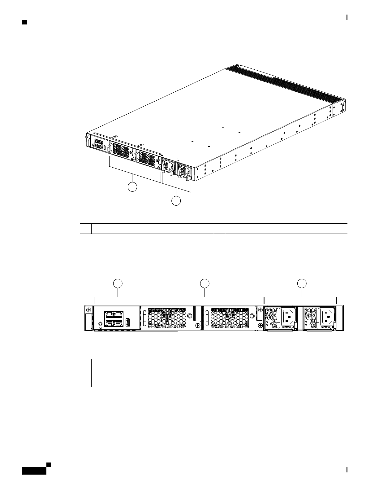
Figure 1-1 Cisco Nexus 5548 Switch Front View
Chapter 1 Cisco Nexus 5500 Platform Overview
1 Two fan modules 2 Two power supplies
Figure 1-2 shows a close-up view of the front of the switch.
Figure 1-2 Cisco Nexus 5548 Switch Front View Close-up
1 Mgmt (10/100/1000) port, console port, and
3 Two power supplies
USB port
2 Two fan modules
The rear of the Cisco Nexus 5548P switch chassis has 32 fixed 10-Gigabit Ethernet ports and 1 slot for
an optional expansion module.
Figure 1-3 shows the rear of the Cisco Nexus 5548P switch.
Cisco Nexus 5000 Series Hardware Installation Guide
1-4
OL-15902-01
Page 21
Chapter 1 Cisco Nexus 5500 Platform Overview
236704
Send documentation comments to nx5000-docfeedback@cisco.com
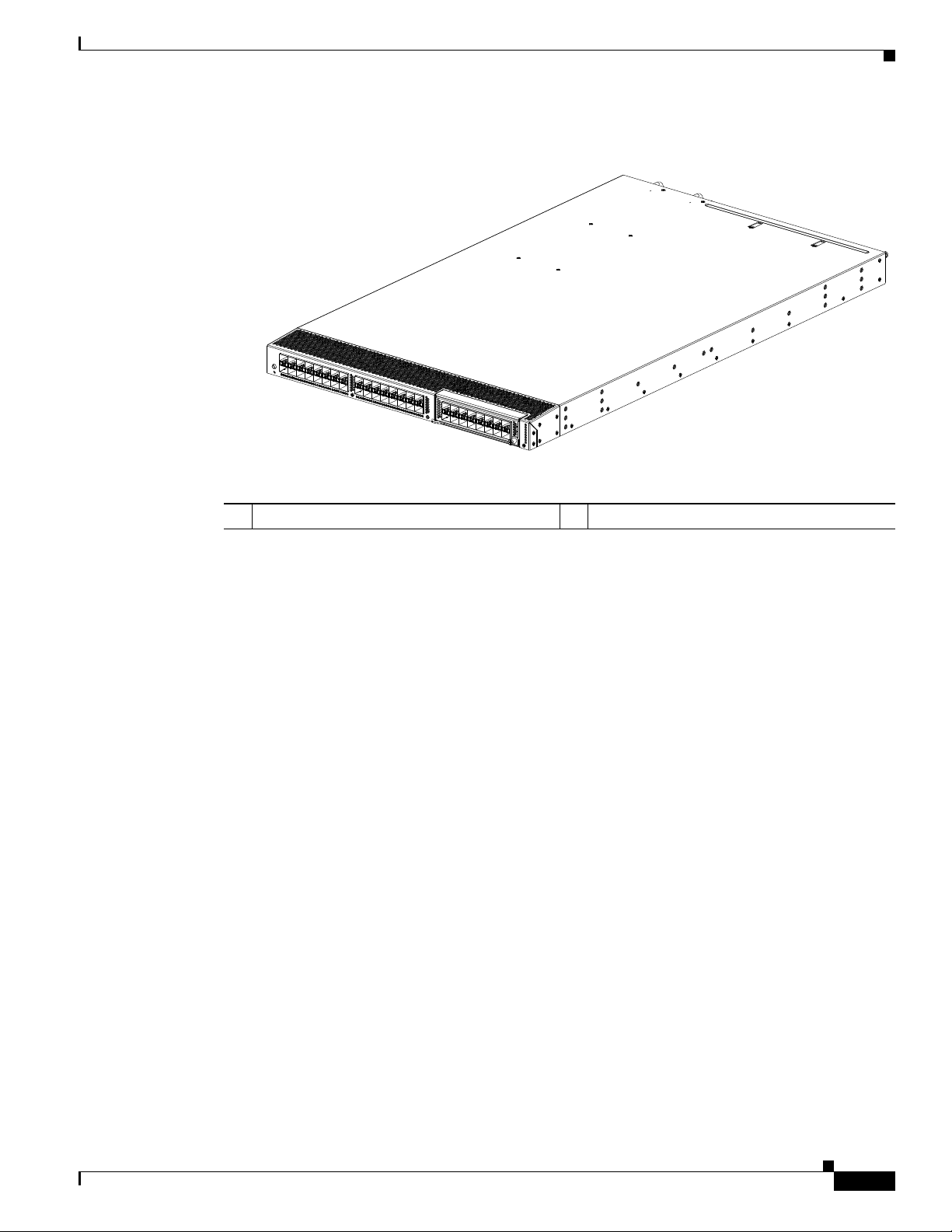
Figure 1-3 Cisco Nexus 5548 Switch Rear View
Cisco Nexus 5548P Switch
1 32 fixed 10-Gigabit Ethernet ports 2 Expansion module
OL-15902-01
Cisco Nexus 5000 Series Hardware Installation Guide
1-5
Page 22
Cisco Nexus 5548P Switch
2 3
1
236705
Send documentation comments to nx5000-docfeedback@cisco.com
Figure 1-4 shows a close-up view of the rear of the Cisco Nexus 5548P chassis.
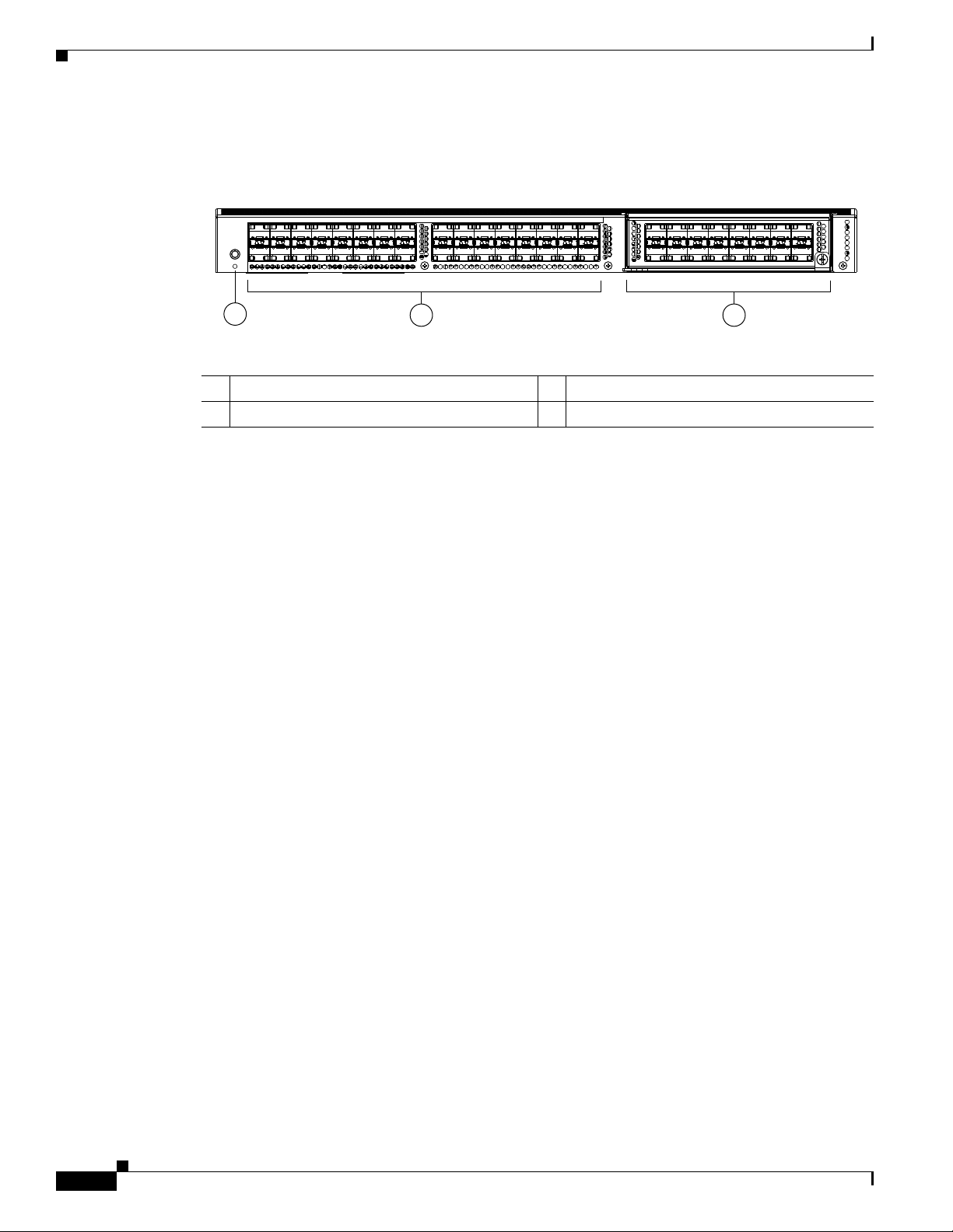
Figure 1-4 Cisco Nexus 5548 Switch Rear View Close-up
1 Status LED 3 1 Expansion module
2 32 fixed 10-Gigabit Ethernet ports
Expansion Modules
Chapter 1 Cisco Nexus 5500 Platform Overview
Expansion modules allow Cisco Nexus switches to be configured as cost-effective 10-Gigabit Ethernet
switches and as I/O consolidation platforms with native Fibre Channel connectivity.
The Cisco Nexus 5500 Platform is equipped with expansion modules that you can use to increase the
number of 10-Gigabit Ethernet and FCoE ports or connect to Fibre Channel SANs with 1-, 2-, 4-, 8-Gbps
Fibre Channel switch ports. The chassis supports hot swapping of the expansion modules.
The Cisco Nexus 5548P supports one of the following expansion modulules:
• N55 M16P Gatos Expansion Module, page 1-6
• N55 M8P8FP Gatos Expansion Module, page 1-7
N55 M16P Gatos Expansion Module
The N55 M16P Gatos Expansion Module (GEM) provides 16 1- or 10-Gigabit Ethernet and FCoE ports
using the small form factor pluggable plus (SFP+) interface.
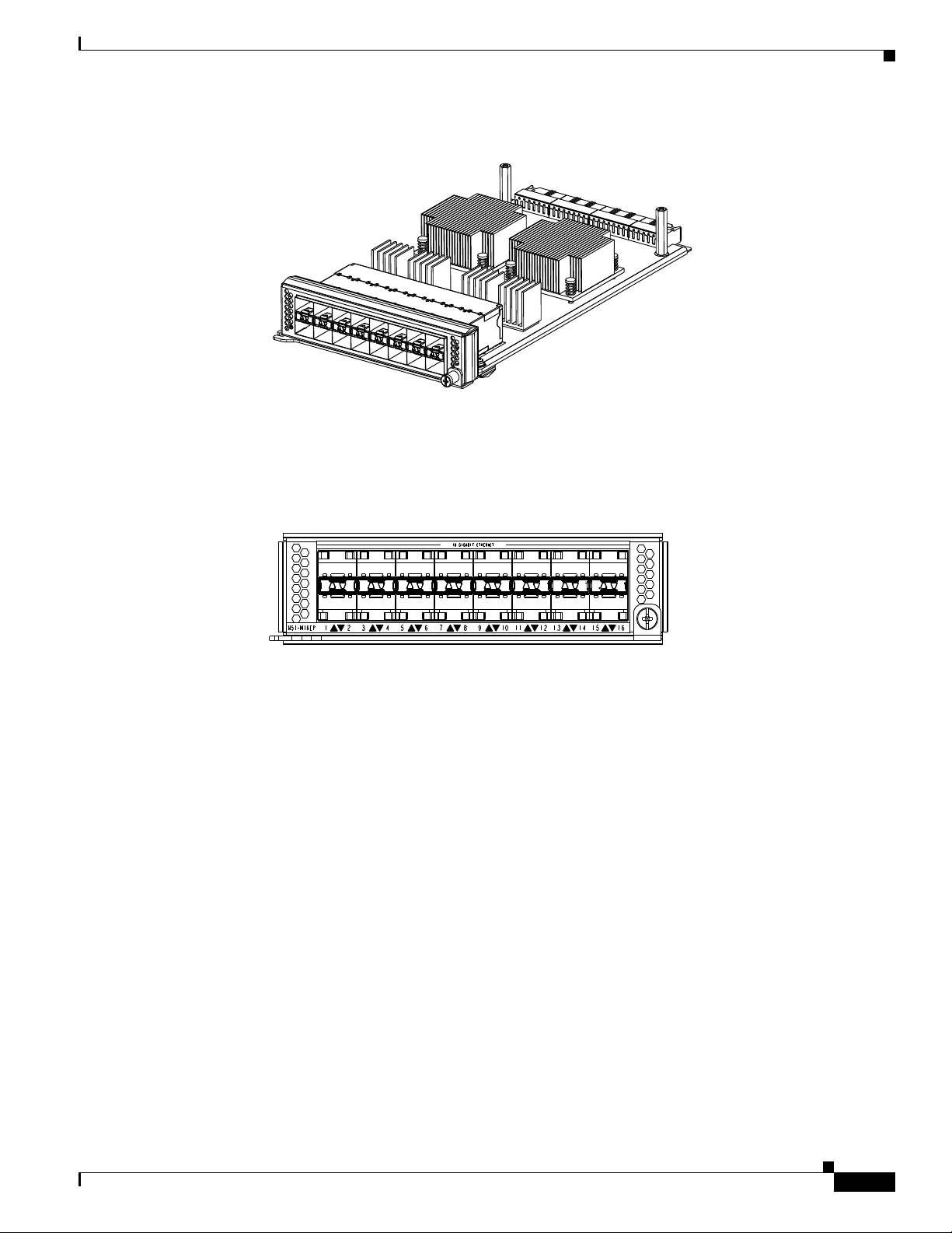
Figure 1-5 shows the N55 M16P GEM.
Figure 1-5 N55 M16P GEM
Cisco Nexus 5000 Series Hardware Installation Guide
1-6
OL-15902-01
Page 23
Chapter 1 Cisco Nexus 5500 Platform Overview
236707
Send documentation comments to nx5000-docfeedback@cisco.com
Figure 1-6 shows a front view of the expansion module.
Cisco Nexus 5548P Switch
236706
Figure 1-6 N55 M16P GEM
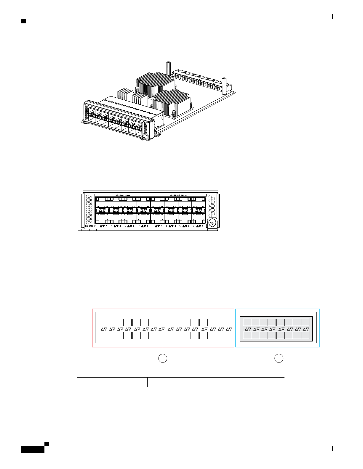
N55 M8P8FP Gatos Expansion Module
The N55 M8P8FP Gatos Expansion Module (GEM) provides 8 1- or 10-Gigabit Ethernet and FCoE ports
using the SFP+ interface and 8 ports of 8-, 4-, 2-, 1 Gbps native Fibre Channel connectivity using the
SFP interface.
Figure 1-7 shows the N55 M8P8FP expansion module.
OL-15902-01
Cisco Nexus 5000 Series Hardware Installation Guide
1-7
Page 24
Cisco Nexus 5548P Switch
1357 911131517192123 25272931
26 28 30 3218 20 22 2410 12 14 162468
13579111315
10 12 14 162468
1 2
236720
Send documentation comments to nx5000-docfeedback@cisco.com
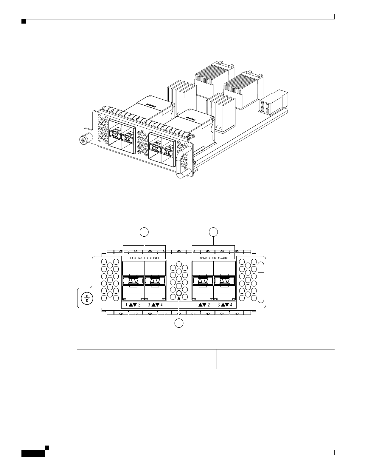
Figure 1-7 N55 M8P8FP Expansion Module.
Figure 1-8 shows a front view of the N55 M8P8FF expansion module.
Figure 1-8 N55 M8P8FP Expansion Module
Chapter 1 Cisco Nexus 5500 Platform Overview
Ports
236709
Each individual port on the Cisco Nexus 5548P switch is numbered, and groups of ports are numbered
based on their function. The ports are numbered from top to bottom and left to right.
Figure 1-9 Port Numbering of the Cisco Nexus 5548P switch with an Expansion Module
1 32 fixed ports 2 Expansion module (N55 M16P or N55 M8P8FP)
Cisco Nexus 5000 Series Hardware Installation Guide
1-8
OL-15902-01
Page 25
Chapter 1 Cisco Nexus 5500 Platform Overview
236710
Send documentation comments to nx5000-docfeedback@cisco.com
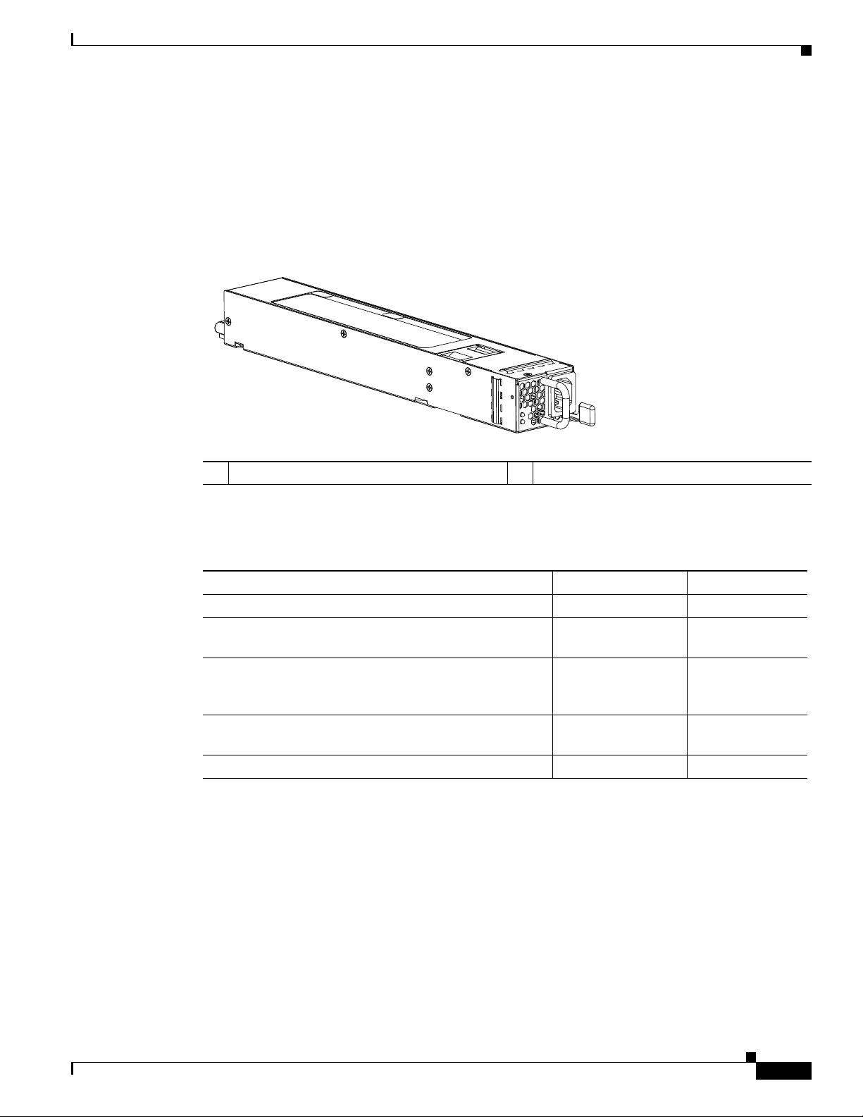
Power Supplies
The Cisco Nexus 5548 switch uses a front-end power supply. The chassis has slots for two power
supplies. Two power supplies can be used for redundancy, but the Cisco Nexus 5548 switch is fully
functional with one power supply.
power status and one for failure condition.
Figure 1-10 Power Supply for t he Cisco Nexus 5548 Switch
Cisco Nexus 5548P Switch
Figure 1-10 shows the power supply, which has two LEDs: one for
1 Amber fail LED indicates a failure condition. 2 Green power LED indicates the power status.
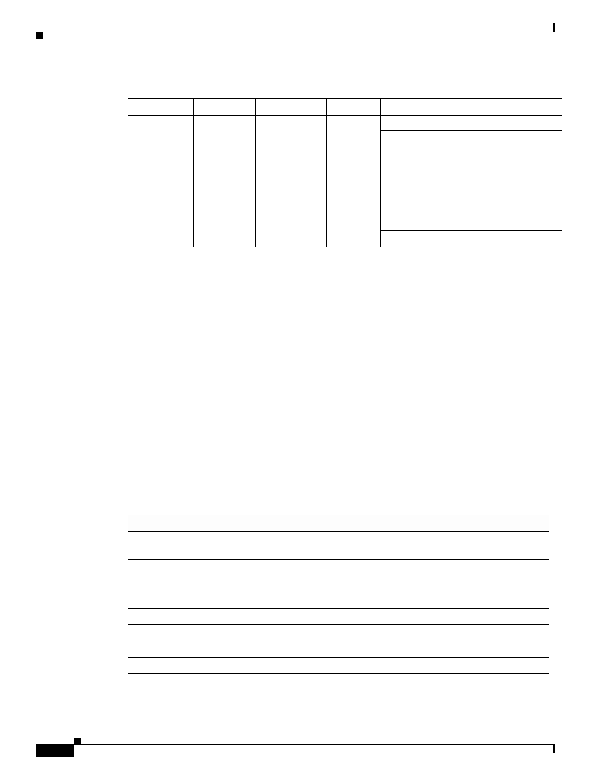
Table 1-1 table lists the LED descriptions for the two power supplies.
Ta b l e 1-1 Power Supply LED Descriptions
Power Supply Condition Power LED Status Fail LED Status
No AC power to all power supplies. Off Off
Power supply failure, including overvoltage, overcurrent,
Off On
overtemperature, and fan failure.
Power supply warning events where the power supply
Off Blinking
continues to operate. These events include high
temperature, high power, and slow fan.
AC present, 3.3 voltage standby (VSB) on, and the power
Blinking Off
supply unit is off.
Power supply on and OK. On Off
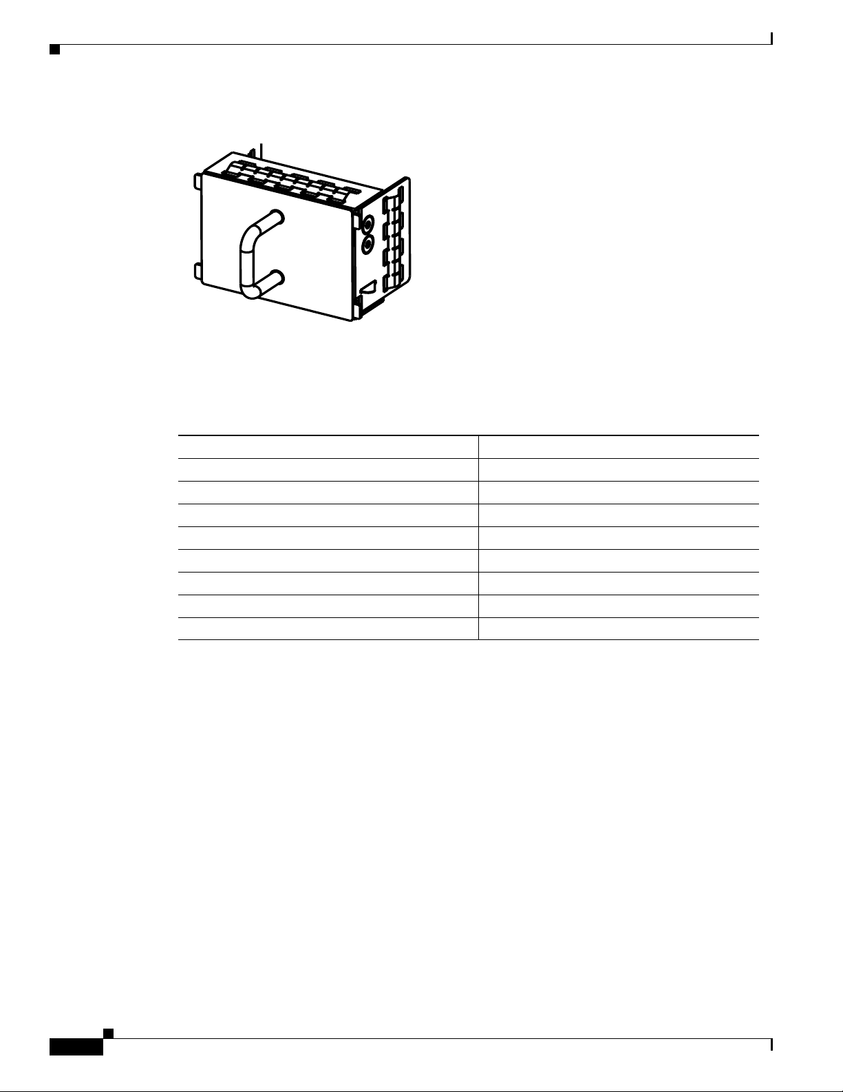
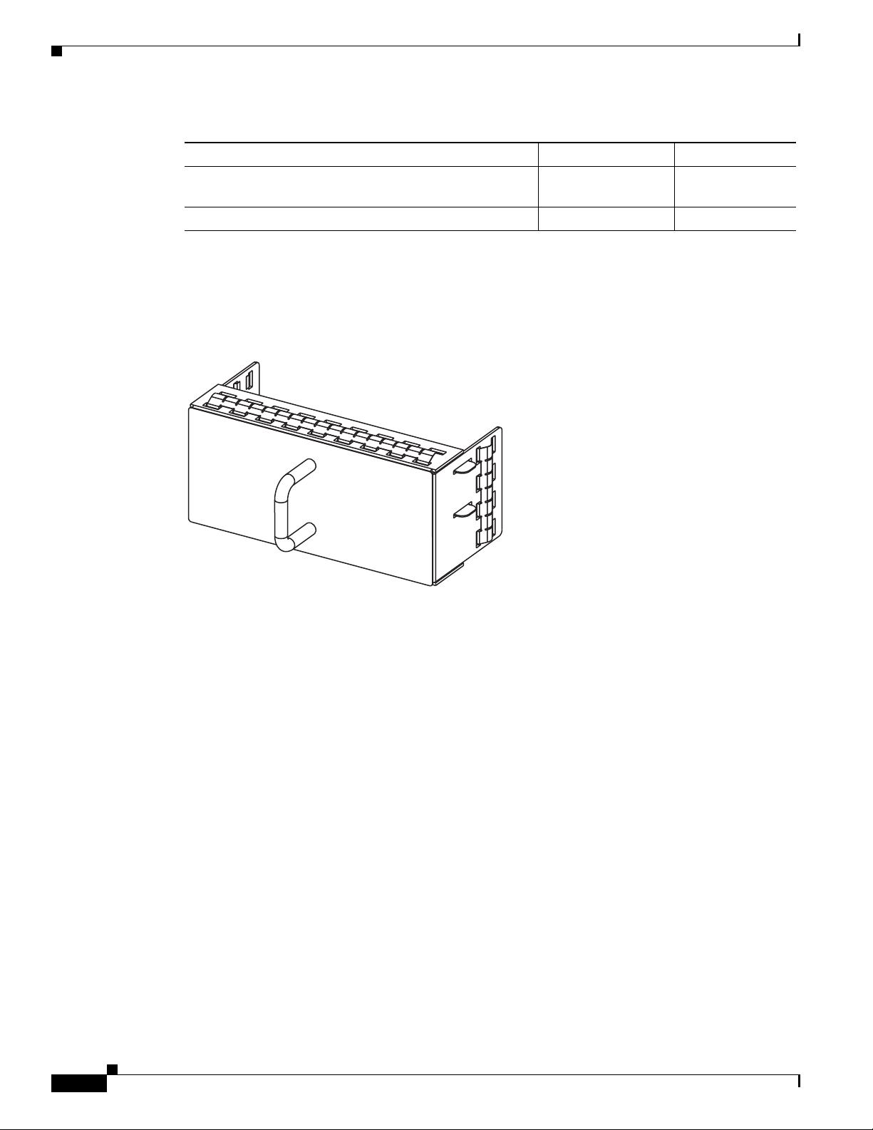
If you have one power supply is installed in the chassis, but the other power supply slot is empty,you
should use a blank fller panel to cover the empty slot. See
Figure 1-11
OL-15902-01
Cisco Nexus 5000 Series Hardware Installation Guide
1-9
Page 26
Cisco Nexus 5548P Switch
236711
Send documentation comments to nx5000-docfeedback@cisco.com
Figure 1-11 Blank Power Supply Filler Panel
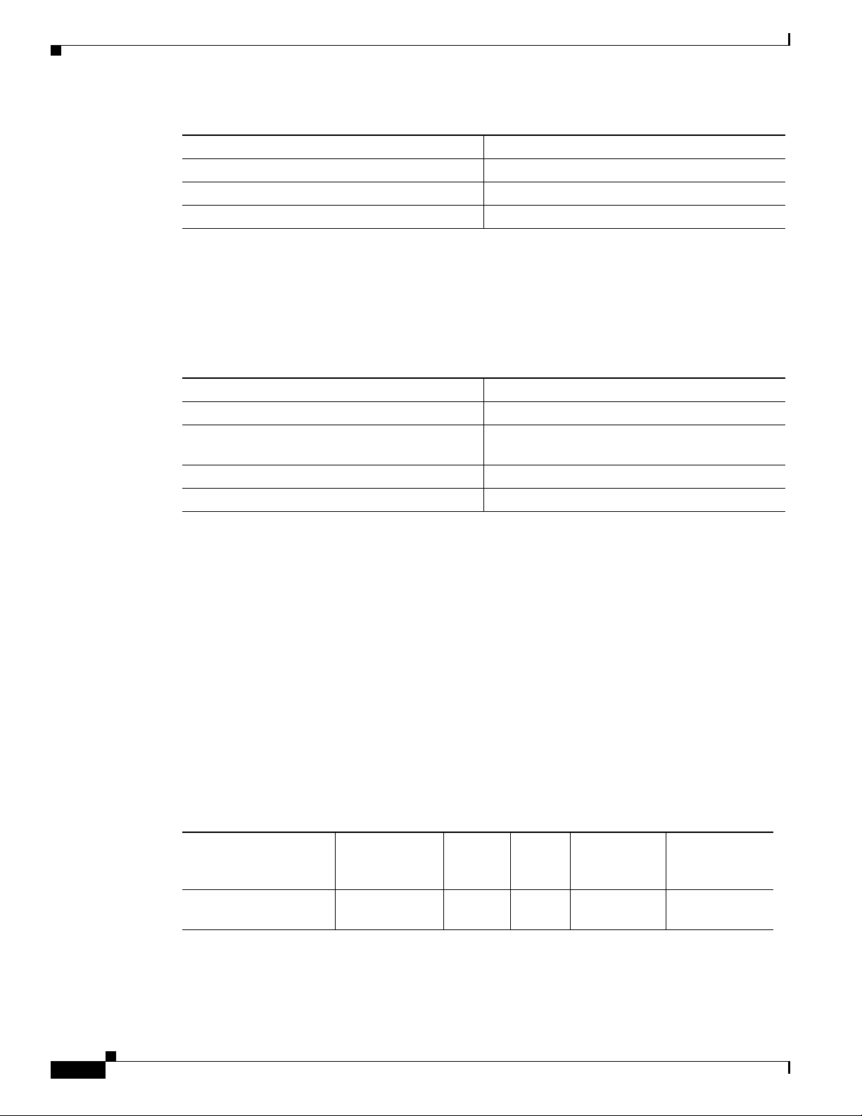
Table 1-2 lists the power supply properties of the Cisco Nexus 5548P.
AC Power Supply Properties Cisco Nexus 5548P Switch
Typical operating power 390 W
Maximum power 600 W (without the Layer 3 daughter card)
Input voltage 100 to 240 VAC
Frequency 50 to 60 Hz
Efficiency 95 to 98% (50 to 100% load)
RoHS compliance Yes
Hot swappable Yes
Heat dissipation 1998 BTU/hr (600 W)
Chapter 1 Cisco Nexus 5500 Platform Overview
Ta b l e 1-2 Power Supply Properties of the Cisco Nexus 5548P Switch
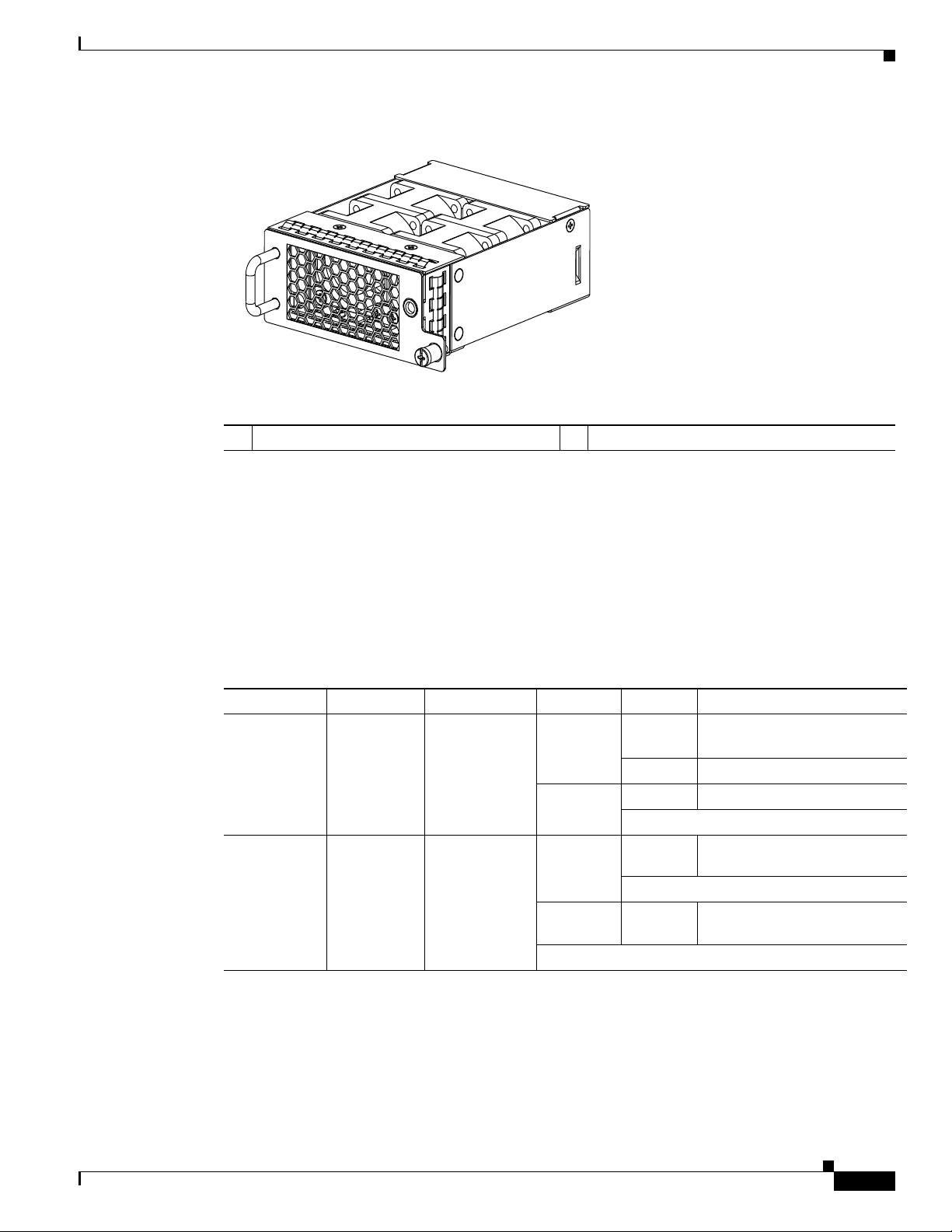
Fan Modules
Cisco Nexus 5000 Series Hardware Installation Guide
1-10
The Cisco Nexus 5548 switch has slots for two fan modules. If you insert two fan modules with six fans
in each module, your switch will have a total of 12 fans.
Figure 1-12 shows the fan module.
OL-15902-01
Page 27
Chapter 1 Cisco Nexus 5500 Platform Overview
236712
Send documentation comments to nx5000-docfeedback@cisco.com
Figure 1-12 Cisco Nexus 5548 Fan Module
1 Fan module LED
The bicolor fan module LED indicates the fan tray health. Green indicates normal operation, while
amber indicates a fan failure.
Cisco Nexus 5548P Switch
LED Descriptions
The switch has three chassis activity LED’s.
Table 1-3 describes the LEDs for the Cisco Nexus 5548 switch.
Ta b l e 1-3 LEDs for the Cisco Nexus 5548 Switch
LED Location Function Color Status Description
Power LED Front of
Fan Tray Status Fan
Chassis
trays (front)
Chassis
Power/Health
Fan tray heath
indicator
(multicolor)
Green Solid On System is on and operating
normally
Off Switch is powered off
Amber On Fault condition
Green Solid On Fan tray is operating
normally
Amber Solid On Fan failure has occurred within the
fan tray
OL-15902-01
Cisco Nexus 5000 Series Hardware Installation Guide
1-11
Page 28
Cisco Nexus 5548P Switch
Send documentation comments to nx5000-docfeedback@cisco.com
Table 1-3 LEDs for the Cisco Nexus 5548 Switch (continued)
LED Location Function Color Status Description
PSU Status
Indicators
Chassis Locator Front of chassis Identify selected
Power supply
(front)
PSU Health
(multi color)
chassis
Green OFF No AC power to power supply
Amber Solid On Power supply failures, overvoltage,
Blue Solid on
Connectivity Options—Transceivers and Cables
The Cisco Nexus 5500 Platform supports a wide variety of 1- and 10-Gigabit Ethernet connectivity
options using Cisco 10GBASE SFP+ modules. In addition, the Cisco Nexus 5548P supports 1-Gigabit
Ethernet connectivity options using 1GBASE SFP modules, 8-, 4-, and 2-Gbps Fibre Channel SFP+ and
4-, 2-, and 1-Gbps Fibre Channel SFP interfaces are supported with expansion module options.
Chapter 1 Cisco Nexus 5500 Platform Overview
Solid On Power supply on and OK
overcurrent, overtemperature
1 Hz
blinking
OFF Operating normally
AC present, 3.3 VSB on,
PSU is off
Chassis is selected
off Chassis is not selected
Transceivers
This section includes the following topics:
• Transceivers, page 1-12
• Cables, page 1-14
The high bandwidth of 10-Gigabit Ethernet poses challenges to transmissions that are met by the
transceiver and cabling options supported by the Cisco Nexus 5500 Platform. Table
Tabl e 1-4 lists the
supported transceiver options.
Ta b l e 1-4 Supported Transceivers
Cisco SFP Description
FET-10G 10G SFP+ module for Cisco Nexus 2000 Series to Cisco Nexus 5000
Series connectivity
Cisco SFP-10G-SR 10GBASE-SR SFP+ module (multimode fiber [MMF])
Cisco SFP-10G-LR 10GBASE-LR SFP+ module (single-mode fiber [SMF])
Cisco SFP-H10GB-CU1M 10GBASE-CU SFP+ cable 1 m (Twinax cable)
Cisco SFP-H10GB-CU3M 10GBASE-CU SFP+ cable 3 m (Twinax cable)
Cisco SFP-H10GB-CU5M 10GBASE-CU SFP+ cable 5 m (Twinax cable)
Cisco GLC-T 1000BASE-T SFP
Cisco GLC-SX-MM GE SFP, LC connector SX transceiver (MMF)
Cisco GLC-LH-SM GE SFP, LC connector LX/LH transceiver (SMF)
Cisco SFP-GE-T 1000BASE-T SFP, extended temperature range
1-12
Cisco Nexus 5000 Series Hardware Installation Guide
OL-15902-01
Page 29

Chapter 1 Cisco Nexus 5500 Platform Overview
Send documentation comments to nx5000-docfeedback@cisco.com
Cisco SFP Description
Cisco SFP-GE-S GE SFP, LC connector SX transceiver (MMF), extended temperature
Cisco-SFP-GE-L GE SFP, LC connector LX/LH transceiver (SMF), extended
Cisco DS-SFP-FC4G-SW 4-Gbps Fibre Channel SW SFP, LC (for Fibre Channel expansion
Cisco DS-SFP-FC4G-LW 4-Gbps Fibre Channel LW SFP, LC (for Fibre Channel expansion
Cisco DS-SFP-FC8G-SW 8-Gbps Fibre Channel SW SFP+, LC (for Fibre Channel expansion
Cisco DS-SFP-FC8G-LW 8-Gbps Fibre Channel LW SFP+, LC (for Fibre Channel expansion
This section includes the fllowing topics:
• SFP+ Transceivers, page 1-13
Cisco Nexus 5548P Switch
range and digital optical monitoring (DOM)
temperature range and DOM
module ports)
module ports)
module ports)
module ports)
SFP+ Transceivers
• SFP+ Copper Cables, page 1-13
• SFP Fiber Channel Transceivers, page 1-14
The enhanced small-form-factor pluggable (SFP+) 10-Gigabit Ethernet transceiver module (see
Table 1-5) is a bidirectional device with a transmitter and receiver in the same physical package. It has
a 20-pin connector on the electrical interface and duplex LC connector on the optical interface.The Cisco
Nexus 5548 switch supports the following SFP+ optical transceivers:
• SR
• DCR, SR-Lite (shorter reach than SR)
• LRM (for uplink only)
• LR (for uplink only)
Ta b l e 1-5 SFP+ Transceivers
Model Description
SFP-10G-SR 10-Gigabit Ethernet—Short range SFP+ module
SFP-10G-LR 10-Gigabit Ethernet—Long range SFP+ module
SFP+ Copper Cables
OL-15902-01
Copper cables are available for use with the 10-Gigabit Ethernet SFP+ module (see Tab le 1-6). The
cables come in the following lengths:
• 1m, 30AWG
• 3m, 28–30 AWG
• 5m, 26–28 AWG
Cisco Nexus 5000 Series Hardware Installation Guide
1-13
Page 30
Cisco Nexus 5548P Switch
Send documentation comments to nx5000-docfeedback@cisco.com
Model Description
SFP-H10GB-CU1M 10GBASE-CU SFP+ cable 1 meter
SFP-H10GB-CU3M 10GBASE-CU SFP+ cable 3 meters
SFP-H10GB-CU5M 10GBASE-CU SFP+ cable 5 meters
SFP Fiber Channel Transceivers
The Cisco Nexus 5548 switch supports the multimode 850 nm 4Gbps SFP with 150 m reach. See
Table 1-7.
Model Description
DS-SFP-FC4G-SW 4-Gbps Fibre Channel-SW SFP, LC
DS-SFP-FC4G-LW 4-Gbps Fibre Channel-LW SFP, LC, (10-km
Cisco DS-SFP-FC8G-SW 8-Gbps Fibre Channel SW SFP+, LC
Cisco DS-SFP-FC8G-LW 8-Gbps Fibre Channel LW SFP+, LC
Chapter 1 Cisco Nexus 5500 Platform Overview
Ta b l e 1-6 SFP+ Copper Cables
Ta b l e 1-7 SFP Fiber Channel Transceivers
reach)
Cables
On the Cisco Nexus 5500 Platforms, you can use an innovative Twinax copper cable that connects to
standard SFP+ connectors for in-rack use, and on optical cable for longer cable runs.
For in-rack or adjacent-rack cabling, the Cisco Nexus 5500 Platform supports SFP+ direct-attach
10-Gigabit Ethernet copper, which integrates transceivers with Twinax cables into an energy efficient,
low-cost, and low-latency solution. SFP+ direct-attach 10-Gigabit Twinax copper cables use only 0.1
watts of power per transceiver and introduce only approximately 0.25 microsecond of latency per link.
For longer cable runs, the Cisco Nexus 5500 Platform supports multimode, short-reach optical SFP+
transceivers. These optical transceivers use approximately 1 W per transceiver and have a latency of
less than 0.1 microsecond.
Table Ta b l e 1-8 shows details of the cables supported:
Ta b l e 1-8 Supported Cables
Power
(each
Connector (Media) Cable Distance
side)
SFP+ CU copper Twina x 5 m ~ 0.1 W ~ 0.1
Transceiver
Latency
(Link)
Standard
SFF 8431
microseconds
1-14
Cisco Nexus 5000 Series Hardware Installation Guide
OL-15902-01
Page 31

Chapter 1 Cisco Nexus 5500 Platform Overview
Send documentation comments to nx5000-docfeedback@cisco.com
Cisco Nexus 5548P Switch
Connector (Media) Cable Distance
SFP+ ACU copper Active Twinax 7 m/
10 m
SFP+ SR MMF and SR MM OM2
MM OM3
82 m/
300 m
Power
(each
side)
Transceiver
Latency
(Link) Standard
~ 0.5 W ~ 6.8
nanoseconds
1 W ~ 0
microseconds
SFF 8461
IEEE 802.3ae
OL-15902-01
Cisco Nexus 5000 Series Hardware Installation Guide
1-15
Page 32

Cisco Nexus 5548P Switch
Send documentation comments to nx5000-docfeedback@cisco.com
Chapter 1 Cisco Nexus 5500 Platform Overview
1-16
Cisco Nexus 5000 Series Hardware Installation Guide
OL-15902-01
Page 33

Send documentation comments to nexus5kdocs@cisco.com
Cisco Nexus 5000 Series Overview
This chapter describes the Cisco Nexus 5000 series switches. This chapter includes the following
sections:
• Cisco Nexus 5020 Switch, page 2-1
• Cisco Nexus 5010 Switch, page 2-17
Cisco Nexus 5020 Switch
This section describes the Cisco Nexus 5020 switches. This section includes the following sections:
• Features, page 2-1
• Chassis, page 2-2
• Ports, page 2-9
• Expansion Modules, page 2-5
• Power Supply, page 2-11
CHAPTER
2
Features
OL-15902-01
• Fan Modules, page 2-12
• LED Descriptions, page 2-14
• Supported SFP Transceivers, page 2-16
The Cisco Nexus 5020 switch is a 2 RU, top-of-rack switch that provides Ethernet and Fibre Channel
consolidation in a single physical cable. The Fibre Channel over Ethernet (FCoE) protocol is used to
consolidate Ethernet and Fibre Channel traffic onto the same physical connection between the server and
the switch. As a top-of-rack switch, all the servers in the rack connect to the Cisco Nexus 5020 switch,
and it connects to the LAN or SAN.
The Cisco Nexus 5020 switch is a part of a family of switches that provide 10-Gigabit Ethernet and
FCoE ports and both 10-Gigabit Ethernet and native 1-, 2-, and 4-Gbps Fibre Channel ports. The
switches provide consolidated I/O connectivity to both production Ethernet LANs and Fibre Channel
SANs in a cost-effective, high-performance, low-latency Ethernet switch.
The Cisco Nexus 5020 switch has the following features:
• Forty fixed 10-Gigabit Ethernet server connection ports on the back of the switch
Cisco Nexus 5000 Series Hardware Installation Guide
2-1
Page 34

Cisco Nexus 5020 Switch
2
1
Send documentation comments to nx5000-docfeedback@cisco.com
Chassis
Chapter 2 Cisco Nexus 5000 Series Overview
• Two slots for optional 10-Gigabit expansion modules or Fibre Channel interfaces on the back of the
switch
• Two slots on the front of the switch for hot swap-capable power supplies
• Five slots on the front of the switch for hot swap-capable fan modules, each of which houses two
fans, that provide front-to-back cooling for the switch
The Cisco Nexus 5020 chassis is 2 RU (3.47 inches) tall, 17.3 inches wide, and 30.0 inches deep. It is
designed to be mounted in a standard 19-inch rack. The switch has two power supplies and five fans
modules on the front of the switch. Ports are at the rear of the switch. The airflow is front to back.
Figure 2-1 shows the front of the Cisco Nexus 5020 switch.
Figure 2-1 Cisco Nexus 5020 Switch Front View
1 Two power supplies 2 Five fan modules
Figure 2-2 shows a close-up view of the front of the switch.
Cisco Nexus 5000 Series Hardware Installation Guide
2-2
OL-15902-01
Page 35

Chapter 2 Cisco Nexus 5000 Series Overview
1 2 3
186265
2
5
6
3 4
1
Send documentation comments to nx5000-docfeedback@cisco.com
Figure 2-2 Cisco Nexus 5020 Switch Front View Close-up
1 Two power supplies 3 System status LED
2 Five fan modules
The rear of the Cisco Nexus 5020 chassis has 40 fixed 10-Gigabit Ethernet ports, 2 slots for optional
expansion modules, an Ethernet connector with 2 cross-connect ports and 2 management ports, a console
port, and 2 AC power connectors.
Cisco Nexus 5020 Switch
Figure 2-3 shows the rear of the Cisco Nexus 5020 switch.
Figure 2-3 Cisco Nexus 5020 Switch Rear View
1 System status LED 4 40 fixed 10-Gigabit Ethernet ports
2 Ethernet connector with two cross-connect
ports on the left (top and bottom), and two
network management ports on the right (top
5 Expansion modules, shown here with two
4-port Fibre Channel plus 4-port 10-Gigabit
Ethernet expansion modules
and bottom)
3 Console port 6 AC power connectors
OL-15902-01
Cisco Nexus 5000 Series Hardware Installation Guide
2-3
Page 36

Cisco Nexus 5020 Switch
5
1
2 4 63
7
186263
1 2
186385
Send documentation comments to nx5000-docfeedback@cisco.com
Figure 2-4 shows a close-up view of the rear of the Cisco Nexus 5020 chassis.
Figure 2-4 Cisco Nexus 5020 Switch Rear View Close-up
Chapter 2 Cisco Nexus 5000 Series Overview
1 System status LED 4 Slot 1, with 40 fixed 10-Gigabit Ethernet
ports (highlighted in red).
2 Ethernet connector with two cross-connect
ports on left side, and two network
management1 (top) and management2
5 Slot 2 for an optional expansion module;
shown here with a 4-port Fibre Channel plus
4-port 10-Gigabit Ethernet expansion module
(bottom) ports on the right side
3 Console port 6 Slot 3 for an optional expansion module;
shown here with a 4-port Fibre Channel plus
4-port 10-Gigabit Ethernet expansion module
The Ethernet connector port exposes four Ethernet ports that are in a 2x2 stacked RJ-45 jack. Figure 2-5
shows a close-up view of the Ethernet connector port.
Figure 2-5 Ethernet Connector Port
1 Internal cross connect ports 2 Network management ports
Cisco Nexus 5000 Series Hardware Installation Guide
2-4
OL-15902-01
Page 37

Chapter 2 Cisco Nexus 5000 Series Overview
Send documentation comments to nx5000-docfeedback@cisco.com
Table 2-1 lists the LED descriptions for all Ethernet LEDs.
Ta b l e 2-1 Ethernet LED Descriptions
LED Status Description
Left Off No link
Right Off No activity
Expansion Modules
Expansion modules allow Cisco Nexus 5000 switches to be configured as cost-effective 10-Gigabit
Ethernet switches and as I/O consolidation platforms with native Fibre Channel connectivity. The Cisco
Nexus 5020 switch has two slots that can be used for the following optional expansion modules:
• Fibre Channel plus Ethernet expansion module with four 10-Gigabit Ethernet Cisco Data Center
Ethernet and FCoE ports and four 1-, 2-, and 4-Gbps Fibre Channel ports
Cisco Nexus 5020 Switch
Solid green Physical link
Blinking green Activity
• Ethernet expansion module with six ports of 10-Gigabit Ethernet Cisco Data Center Ethernet and
FCoE
The chassis supports hot swapping of the expansion modules
This section includes the following topics:
• Fibre Channel Plus Ethernet Expansion Module, page 2-5
• Ethernet Expansion Module, page 2-7
• N5K-M1008 Gatos Expansion Module, page 2-7
• N5K-M1060 Gatos Expansion Module, page 2-8
Fibre Channel Plus Ethernet Expansion Module
The Fibre Channel plus Ethernet expansion module supports four SFP+ transceiver modules and four 1-,
2-, 4-Gbps Fibre Channel transceivers. The Fibre Channel plus Ethernet expansion module is a
field-replaceable unit (FRU).
Figure 2-6 shows the Fibre Channel plus Ethernet expansion module.
OL-15902-01
Cisco Nexus 5000 Series Hardware Installation Guide
2-5
Page 38
Cisco Nexus 5020 Switch
186384
1234 1234
10 GIGABIT ETHERNET
1/2/4G FIBRE CHANNEL
186258
1 3
2
Send documentation comments to nx5000-docfeedback@cisco.com
Figure 2-6 Fibre Channel Plus Ethernet Expansion Module
Chapter 2 Cisco Nexus 5000 Series Overview
Figure 2-7 shows the front of the Fibre Channel plus Ethernet expansion module. Figure 2-13 shows how
ports are numbered on the Fibre Channel plus Ethernet expansion module.
Figure 2-7 Front View of the Fibre Channel Plus Ethernet Expansion Module f
1 Four 10-Gigabit Ethernet ports 3 Four 1-, 2-, 4-Gbps Fibre Channel ports
2 Module LED
See Figure 2-13 for an illustration of how ports are grouped and numbered on the Fibre Channel plus
Ethernet expansion module.
Cisco Nexus 5000 Series Hardware Installation Guide
2-6
OL-15902-01
Page 39

Chapter 2 Cisco Nexus 5000 Series Overview
186259
12
3
4
5
6
10 GIGABIT ETHERNET
1 3
2
Send documentation comments to nx5000-docfeedback@cisco.com
Ethernet Expansion Module
The Ethernet expansion module supports six 10-Gigabit Ethernet ports, four of which will have
encryption capability. The Ethernet expansion module is a field-replaceable unit (FRU).
shows the Ethernet expansion module.
Figure 2-8 Ethernet Expansion Module
Cisco Nexus 5020 Switch
Figure 2-8
1 10-Gigabit Ethernet ports 3 10-Gigabit Ethernet ports
2 Module LED
See Figure 2-14 for an illustration of how ports are grouped and numbered on the Ethernet expansion
module.
N5K-M1008 Gatos Expansion Module
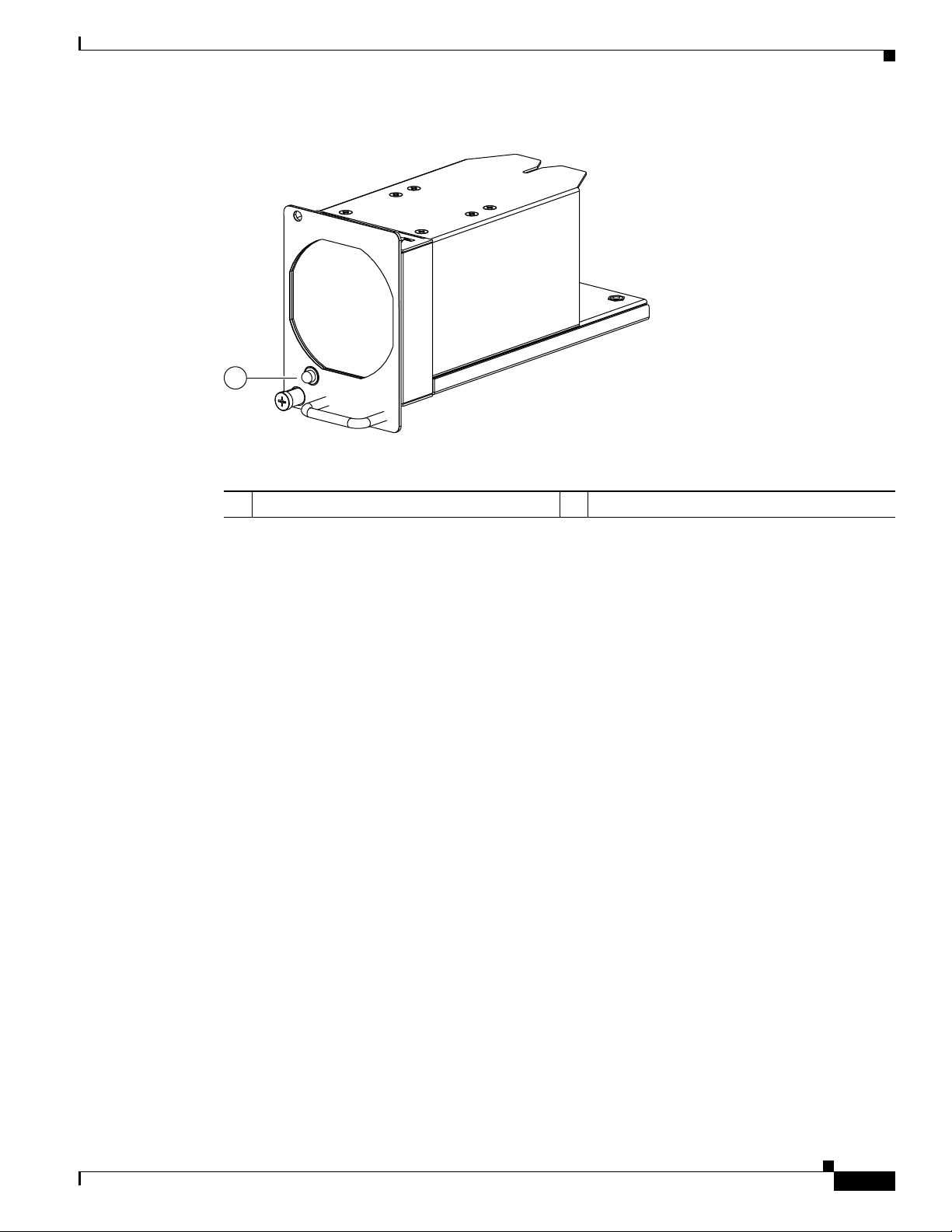
The N5K-M1008 GEM supports 8 1/2/4G Fiber Channel, SFP-based uplink connection. Figure 2-9
shows the N5K-M1008 GEM.
OL-15902-01
Cisco Nexus 5000 Series Hardware Installation Guide
2-7
Page 40

Cisco Nexus 5020 Switch
189953
189954
2
1
2
3
4
5
6
7
8
1
Send documentation comments to nx5000-docfeedback@cisco.com
Figure 2-9 N5K-M1008 GEM
Chapter 2 Cisco Nexus 5000 Series Overview
Figure 2-10 Front View of the N5K-M1008 GEM
1 Eight 1-, 2-, 4-Gbps Fibre Channel ports 2 LED
N5K-M1060 Gatos Expansion Module
The N5K-M1060 xpansion module provides 6 EA 1/2/4/8G line rate Fiber Channel, SFP+ based uplink
connections.
Figure 2-11 and Figure 2-12 show the N5K-M1060 GEM.
2-8
Cisco Nexus 5000 Series Hardware Installation Guide
OL-15902-01
Page 41

Chapter 2 Cisco Nexus 5000 Series Overview
196118
Send documentation comments to nx5000-docfeedback@cisco.com
Figure 2-11 N5K-M1060 GEM
Cisco Nexus 5020 Switch
Ports
Figure 2-12 Front View of the N5K-M1060 GEM
1
1/2/4/8G FIBRE CHANNEL
4
1
2
3
5
2
1 Six 1-, 2-, 4-, 8-Gbps Fibre Channel ports 2 LED
6
196117
OL-15902-01
Each individual port on the Cisco Nexus 5020 switch is numbered, and groups of ports are numbered
based on their function. The ports are numbered top to bottom and left to right. The 40 fixed ports form
group 1 and are named 1/port_number. Ports 1 through 32 are unencrypted Ethernet ports. Of these, ports
1 through 16 are 10-Gigabit Ethernet and 1-Gigabit Ethernet capable ports. Ports 33 through 40 are
encryption-capable Ethernet ports.
Group 2 includes the ports in the top-most expansion module. Group 2, ports 1 through 4, are encrypted
Ethernet ports. Group 2, ports 5 through 8, are Fibre Channel ports.
Cisco Nexus 5000 Series Hardware Installation Guide
2-9
Page 42

Cisco Nexus 5020 Switch
A B C D E
A B C D E
186387
Send documentation comments to nx5000-docfeedback@cisco.com
Group 3 includes the ports in the bottom-most expansion module. Group 3 ports 1 through 4 are
encrypted Ethernet ports. Group 3 ports 5 through 8 are Fibre Channel ports.
Figure 2-13 shows how ports are numbered and grouped by function for both the fixed ports and the
Fibre Channel plus Ethernet expansion module ports.
Figure 2-13 Port Numbering of Fixed Ports and Fibre Channel Plus Ethernet Expansion Module
Chapter 2 Cisco Nexus 5000 Series Overview
Ports
A Group 1, ports 1 through 16: 10-Gigabit
Ethernet and 1-Gigabit Ethernet capable
unencrypted ports
B Group 1, ports 1 through 32: Unencrypted
Ethernet ports
C Group 1, ports 33 through 40: Encrypted
Ethernet ports
Figure 2-14 shows how ports are numbered and grouped by function for both the fixed ports and the
Ethernet expansion module ports.
Figure 2-14 Port Numbering of Fixed Ports and the Ethernet Expansion Module
D Groups 2 and 3, ports 1 through 4: Encrypted
Ethernet ports
E Groups 2 and 3, ports 5 through 8: Fibre
Channel ports
2-10
Cisco Nexus 5000 Series Hardware Installation Guide
OL-15902-01
Page 43

Chapter 2 Cisco Nexus 5000 Series Overview
1
2
186264
Send documentation comments to nx5000-docfeedback@cisco.com
Cisco Nexus 5020 Switch
Power Supply
A Group 1, ports 1 through 16: 10-Gigabit
Ethernet and 1-Gigabit Ethernet capable
D Groups 2 and 3, ports 1 through 4: Encrypted
Ethernet ports
Encrypted ports
B Group 1, ports 1 through 32: Unencrypted
Ethernet ports
E Groups 2 and 3, ports 5 through 6:
Unencrypted Ethernet ports
C Group 1, ports 33 through 40: Encrypted
Ethernet ports
The Cisco Nexus 5020 switch uses a front-end power supply. The chassis has slots for two power
supplies. Two power supplies can be used for redundancy, but the Cisco Nexus 5020 switch is fully
functional with one power supply.
Figure 2-15 shows the power supply, which has two LEDs: one for
the power status and one for the failure condition.
Figure 2-15 Power Supply for the Cisco Nexus 5020 Switch
OL-15902-01
1 Green power LED indicates the power status. 2 Amber fail LED indicates a failure condition.
Table 2-2 table describes the status of the two power supply LEDs.
Ta b l e 2-2 Power Supply LED Descriptions
Power Supply Condition Power LED Status Fail LED Status
No AC power to all power supplies. Off Off
Power supply failure, including overvoltage, overcurrent,
Off On
overtemperature, and fan failure.
Power supply warning events where the power supply
Off Blinking
continues to operate. These events include high
temperature, high power, and slow fan.
Cisco Nexus 5000 Series Hardware Installation Guide
2-11
Page 44
Cisco Nexus 5020 Switch
Send documentation comments to nx5000-docfeedback@cisco.com
Table 2-2 Power Supply LED Descriptions (continued)
Power Supply Condition Power LED Status Fail LED Status
AC present, 3.3 voltage standby (VSB) on, and the power
supply unit is off.
Power supply on and OK. On Off
If you have one power supply installed in the chassis, but the other power supply slot is empty, you
should use a blank filler panel to cover the empty slot.
panel.
Figure 2-16 Blank Power Supply Filler Panele
Chapter 2 Cisco Nexus 5000 Series Overview
1 Hz blinking Off
Figure 2-16 shows a blank power supply filler
Fan Modules
186854
The Cisco Nexus 5020 switch has five fan modules. Figure 2-17 shows the fan module.
2-12
Cisco Nexus 5000 Series Hardware Installation Guide
OL-15902-01
Page 45
Chapter 2 Cisco Nexus 5000 Series Overview
1
186263
Send documentation comments to nx5000-docfeedback@cisco.com
Figure 2-17 Cisco Nexus 5020 Fan Module
Cisco Nexus 5020 Switch
1 Fan module LED
The bicolor fan module LED indicates the fan tray health. Green indicates normal operation, while
amber indicates a fan failure.
OL-15902-01
Cisco Nexus 5000 Series Hardware Installation Guide
2-13
Page 46

Cisco Nexus 5020 Switch
Send documentation comments to nx5000-docfeedback@cisco.com
LED Descriptions
Table 2-3 describes the LEDs for the Cisco Nexus 5020 switch.
Ta b l e 2-3 LEDs for the Cisco Nexus 5020 Switch
LED Location Function Color Status Description
Chassis Front and back
of chassis
Chassis
power and
health
Chapter 2 Cisco Nexus 5000 Series Overview
Green Solid on All diagnostics pass. The
module is operational.
Off The module is not receiving
power.
Amber On The module is booting or
running diagnostics.
An overtemperature condition
has occurred. The temperature
threshold has been exceeded
by a small value during
environmental monitoring.
Blinking An overtemperature condition
has occurred. The temperature
threshold has been exceeded
by a large value during
environmental monitoring.
If the module fails during an
initial reset, the LED
continues to blink and the
module does not come online.
Fan module Fan modules
(front)
Fan
module
health
indicator
The module has a runtime
failure and is brought offline.
Green Solid on All diagnostics pass. The
module is operational.
Off The module is not receiving
power.
Amber Solid on The module is booting or
running diagnostics.
Amber Blinking If the module fails during an
initial reset, the LED
continues to blink and the
module does not come online.
The module has a runtime
failure and is brought offline.
2-14
Cisco Nexus 5000 Series Hardware Installation Guide
OL-15902-01
Page 47

Chapter 2 Cisco Nexus 5000 Series Overview
Send documentation comments to nx5000-docfeedback@cisco.com
Table 2-3 LEDs for the Cisco Nexus 5020 Switch (continued)
LED Location Function Color Status Description
Power supply Power supply
(front)
Module Back of chassis Indicator
Power
supply
health
of a fault
with any
expansion
module
Cisco Nexus 5020 Switch
Green Solid on Power supply is on and okay.
Off No AC power to the power
supply.
Amber Solid on Power supply failures, over
voltage, over current, over
temperature.
Blinking AC is present, 3.3 VSB on, and
the power supply is off.
Off Operating normally.
Green On All diagnostics pass. The
module is operational.
Off The module is not receiving
power.
Amber Solid on The module is booting or
running diagnostics.
Port LED Back of the
chassis
Indicates
LED status
An overtemperature condition
has occurred. The temperature
threshold has been exceeded
by a small value during
environmental monitoring.
Blinking An overtemperature condition
has occurred. The temperature
threshold has been exceeded
by a large value during
environmental monitoring.
If the module fails during an
initial reset, the LED
continues to blink and the
module does not come online.
The module has a runtime
failure and is brought offline
Green Off The port is not active or the link
is not connected.
Solid on The port is active. The link is
connected and operational.
Amber Solid on The module or port is disabled
through the CLI command or
the module is initializing.
Blinking The port is faulty and has been
disabled.
OL-15902-01
Cisco Nexus 5000 Series Hardware Installation Guide
2-15
Page 48

Cisco Nexus 5020 Switch
Send documentation comments to nx5000-docfeedback@cisco.com
Supported SFP Transceivers
The Cisco Nexus 5020 switch supports both SFP+ Ethernet transceivers and SFP Fibre Channel
transceivers.
This section includes the following sections:
• SFP+ Transceivers, page 2-16
• SFP+ Copper Cables, page 2-16
• SFP Fiber Channel Transceivers, page 2-17
SFP+ Transceivers
The enhanced Small-Form-Factor Pluggable (SFP+) 10-Gigabit Ethernet transceiver module is a
bidirectional device with a transmitter and receiver in the same physical package. See
a 20-pin connector on the electrical interface and duplex LC connector on the optical interface.The Cisco
Nexus 5020 switch supports the SFP-10G-SR transceiver.
Chapter 2 Cisco Nexus 5000 Series Overview
Table 2-4 . It has
Ta b l e 2-4 SFP+ Transceivers
Model Description
SFP-10G-SR
10-Gigabit Ethernet—short range SFP+ module
Figure 2-18 shows the SFP-10G-SR transceiver.
Figure 2-18 SFP+ 10-Gigabit Ethernet Transceiver Module
187492
SFP+ Copper Cables
Copper cables are available for use with the 10-Gigabit Ethernet SFP+ module. See Tab le 2-5. The
cables come in the following lengths:
• 1m, 30AWG
• 3m, 28-30 AWG
Cisco Nexus 5000 Series Hardware Installation Guide
2-16
OL-15902-01
Page 49

Chapter 2 Cisco Nexus 5000 Series Overview
Send documentation comments to nx5000-docfeedback@cisco.com
• 5m, 26-28 AWG
Model Description
SFP-H10GB-CU1M 10GBASE-CU SFP+ Cable 1 Meter
SFP-H10GB-CU3M 10GBASE-CU SFP+ Cable 3 Meter
SFP-H10GB-CU5M 10GBASE-CU SFP+ Cable 5 Meter
SFP Fiber Channel Transceivers
The Cisco Nexus 5020 switch also supports the following SFP Fibre Channel transceivers (See
Table 2-6) :
Cisco Nexus 5010 Switch
Ta b l e 2-5 SFP+ Copper Cables
Ta b l e 2-6 SFP Fiber Channel Transceivers
Model Description
DS-SFP-FC4G-SW 4-Gbps/2-Gbps/1-Gbps Fibre Channel—short
Cisco Nexus 5010 Switch
This section describes the Cisco Nexus 5010 switch and its components. This section includes the
following topics:
• Features, page 2-18
• Chassis, page 2-18
• Expansion Modules, page 2-22
• Ports, page 2-26
• Power Supplies, page 2-28
• Fan Modules, page 2-29
• LED Descriptions, page 2-30
• Supported SFP Transceivers, page 2-31
wavelength SFP module
OL-15902-01
Cisco Nexus 5000 Series Hardware Installation Guide
2-17
Page 50

Cisco Nexus 5010 Switch
Send documentation comments to nx5000-docfeedback@cisco.com
Features
Chapter 2 Cisco Nexus 5000 Series Overview
The Cisco Nexus 5010 switch is a 1RU, top-of-rack switch that provides Ethernet and Fibre Channel
consolidation in a single physical cable. The Fibre Channel over Ethernet (FCoE) protocol is used to
consolidate Ethernet and Fibre Channel traffic onto the same physical connection between the server and
the switch. As a top-of-rack switch, all the servers in the rack connect to the Cisco Nexus 5010 switch,
and it connects to the LAN or SAN.
The Cisco Nexus 5010 switch is a part of a family of switches that provide 10-Gigabit Ethernet and FCoE
ports and both 10-Gigabit Ethernet and native 1-, 2-, and 4-Gbps Fibre Channel ports. The switches
provide consolidated I/O connectivity to both production Ethernet LANs and Fibre Channel SANs in a
cost-effective, high-performance, low-latency Ethernet switch.
The Cisco Nexus 5010 switch has the following features:
• One slot on the back of the switch for an optional uplink Gatos Expansion Module [GEM]. The
following modules can be inserted into this slot: N5K-M1404, N5K-M1600 and N5K-M1008.
• Twenty to twenty-eight ports on the back of the switch depending on which GEM is installed.
Twenty ports on Cisco Nexus 5010 switch belong to the base switch. Additionally, you an insert a a
module with six or eight ports.
• Two slots on the front of the switch for hot swap-capable power supplies.
• Two slots on the front of the switch for fan modules. Each fan module houses six fans. The
combination of six fans per module and two modules provides the switch with a total of 12-fans.
Chassis
The Cisco Nexus 5010 chassis is 1 RU, 1.72 inches tall, 17.3 inches wide and 30.0 inches deep. It is
designed to be mounted in a standard 19-inch rack. The switch has two power supplies and two fans
modules on the front of the switch. Ports are at the rear of the switch. The airflow is front to back.
Figure 2-19 shows the front view of the Cisco Nexus 5010 switch.
Figure 2-19 Cisco Nexus 5010 Switch Front View
1
2
189949
2-18
Cisco Nexus 5000 Series Hardware Installation Guide
OL-15902-01
Page 51

Chapter 2 Cisco Nexus 5000 Series Overview
189950
1
2
3
Send documentation comments to nx5000-docfeedback@cisco.com
1 Two power supplies 2 Two fan modules
Figure 2-20 shows a close-up view of the front of the switch.
Figure 2-20 Cisco Nexus 5010 Switch Front View Close-up
Cisco Nexus 5010 Switch
1 Two power supplies 3 System status LED
2 Two fan modules
The rear of the Cisco Nexus 5010 chassis has 20 fixed 10-Gigabit Ethernet ports, 1 slot for an optional
expansion module, an Ethernet connector with 2 cross-connect ports and 2 management ports, a console
port, and 2 AC power connectors.
Figure 2-21 Cisco Nexus 5010 Switch Rear View
Figure 2-21 shows the rear of the Cisco Nexus 5010 switch.
1
2
3 4
5
189951
6
OL-15902-01
Cisco Nexus 5000 Series Hardware Installation Guide
2-19
Page 52

Cisco Nexus 5010 Switch
Send documentation comments to nx5000-docfeedback@cisco.com
1 System status LED 4 20 fixed 10-Gigabit Ethernet ports
2 Ethernet connector with two cross-connect
3 Console port 6 AC power connectors
Chapter 2 Cisco Nexus 5000 Series Overview
5 Expansion modules
ports on the left (top and bottom), and two
network management ports on the right (top
and bottom)
2-20
Cisco Nexus 5000 Series Hardware Installation Guide
OL-15902-01
Page 53

Chapter 2 Cisco Nexus 5000 Series Overview
1 2
186385
Send documentation comments to nx5000-docfeedback@cisco.com
Figure 2-22 shows a close-up view of the rear of the Cisco Nexus 5010 chassis.
Figure 2-22 Cisco Nexus 5010 Switch Rear View Close-up
1
Cisco Nexus 5010 Switch
189952
3
2
4
5
6
1 System status LED 4 Slot 1, with 20 fixed 10-Gigabit Ethernet
ports (highlighted in red).
2 Ethernet connector with two cross-connect
5 Slot 2 for an optional expansion module
ports on left side and two network
management1 (top) and management2
(bottom) ports on the right side
3 Console port 6 AC power connectors
The Ethernet connector port exposes four Ethernet ports that are in a 2x2 stacked RJ-45 jack. Figure 2-23
shows a close-up view of the Ethernet connector port.
Figure 2-23 Ethernet Connector Port
1 Internal cross connect ports 2 Network management ports
OL-15902-01
Cisco Nexus 5000 Series Hardware Installation Guide
2-21
Page 54

Cisco Nexus 5010 Switch
Send documentation comments to nx5000-docfeedback@cisco.com
Table 2-7 lists the LED descriptions for all Ethernet LEDs.
Ta b l e 2-7 Ethernet LED Descriptions
LED Status Description
Left Off No link
Right Off No activity
Expansion Modules
Expansion modules allow Cisco Nexus 5000 switches to be configured as cost-effective 10-Gigabit
Ethernet switches and as I/O consolidation platforms with native Fibre Channel connectivity. The Cisco
Nexus 5010 switch has one slot for an optional uplink Gatos Expansion Module (GEM). The following
modules can be inserted in this slot: N5K-M1404, N5K-M1600, N5K-M1008 and N5K-M1060.
• N5K-M1404 provides 4 10G SFP+, and 4 Fiber Channel 1/2/4G SFP based uplink connections. The
10-Gigabit Ethernet ports are encryption capable.
Chapter 2 Cisco Nexus 5000 Series Overview
Solid green Physical link
Blinking green Activity
• M5K-M1600 provides 6 10G SFP+ based uplink connections.
• N5K-M1008 provides 8 1-, 2-, and 4- Gps Fiber Channel, SFP based uplink connection.
• N5K-M1060 provides 6 1-, 2-, 4-, and 8-Gbps line rate Fiber Channel, SFP+ based uplink
connections.
The chassis supports hot swapping of the expansion modules.
This section includes the fllowing topics:
• N5K-M1404 Gatos Expansion Module, page 2-22
• N5K-M1600 Gatos Expansion Module, page 2-23
• N5K-M1008 Gatos Expansion Module, page 2-24
• N5K-M1060 Gatos Expansion Module, page 2-25
N5K-M1404 Gatos Expansion Module
The N5K-M1404 GEM supports four SFP+ transceiver modules and four 1-, 2-, 4-Gbps Fibre Channel
transceivers. The N5K-M1404 Fibre Channel plus Ethernet expansion module is a field-replaceable unit
(FRU).
Figure 2-24 shows the Fibre Channel plus Ethernet expansion module.
2-22
Cisco Nexus 5000 Series Hardware Installation Guide
OL-15902-01
Page 55

Chapter 2 Cisco Nexus 5000 Series Overview
186384
1234 1234
10 GIGABIT ETHERNET
1/2/4G FIBRE CHANNEL
186258
1 3
2
Send documentation comments to nx5000-docfeedback@cisco.com
Figure 2-24 N5K-M1404 Gatos Expansion Module
Cisco Nexus 5010 Switch
Figure 2-25 shows the front of the N5K-M1404 GEM . Figure 2-13 shows how ports are numbered on
the GEM.
Figure 2-25 Front of the N5K-M1404 GEM
1 Four 10-Gigabit Ethernet ports 3 Four 1-, 2-, 4-Gbps Fibre Channel ports
2 Module LED
N5K-M1600 Gatos Expansion Module
OL-15902-01
The N5K-M1600 GEM supports 6 10G SFP+ based uplink connections. Figure 2-26 shows the
N5K-M1600 GEM.
Cisco Nexus 5000 Series Hardware Installation Guide
2-23
Page 56

Cisco Nexus 5010 Switch
186259
12
3
4
5
6
10 GIGABIT ETHERNET
1 3
2
189953
Send documentation comments to nx5000-docfeedback@cisco.com
Figure 2-26 N5K-M1600 GEM
1 10-Gigabit Ethernet ports 3 10-Gigabit Ethernet ports
2 Module LED
Chapter 2 Cisco Nexus 5000 Series Overview
See Figure 2-14 for an illustration of how ports are grouped and numbered on the Ethernet expansion
module.
N5K-M1008 Gatos Expansion Module
The N5K-M1008 GEM supports 8 1/2/4G Fiber Channel, SFP-based uplink connection. Figure 2-27 and
Figure 2-28 show the N5K-M1008 GEM.
Figure 2-27 N5K-M1008 GEM
2-24
Cisco Nexus 5000 Series Hardware Installation Guide
OL-15902-01
Page 57
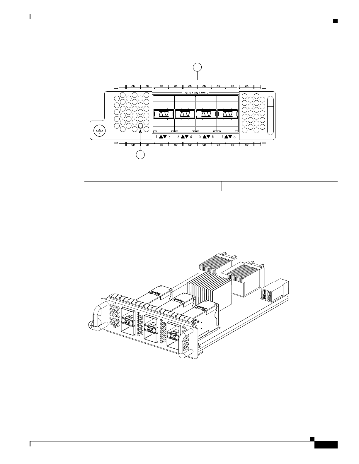
Chapter 2 Cisco Nexus 5000 Series Overview
189954
2
1
2
3
4
5
6
7
8
1
196118
Send documentation comments to nx5000-docfeedback@cisco.com
Figure 2-28 Front View of the N5K-M1008 GEM
Cisco Nexus 5010 Switch
1 Eight 1-, 2-, 4-Gbps Fibre Channel ports 2 LED
N5K-M1060 Gatos Expansion Module
The N5K-M1060 expansion module provides 6 EA 1-, 2-, 4-, 8-Gbps line rate Fiber Channel, SFP+
based uplink connections.
Figure 2-29 N5K-M1060 GEM
Figure 2-27 shows the N5K-M1060 GEM.
OL-15902-01
Cisco Nexus 5000 Series Hardware Installation Guide
2-25
Page 58

Cisco Nexus 5010 Switch
123
4
567
8
1234567
8
9101112131415
16
171819
20
1
2
A B C D E
192241
Send documentation comments to nx5000-docfeedback@cisco.com
Figure 2-30 Front of the N5K-M1060 GEM
Chapter 2 Cisco Nexus 5000 Series Overview
1
1/2/4/8G FIBRE CHANNEL
Ports
4
1
2
3
6
5
196117
2
1 Six 1-, 2-, 4-, 8-Gbps Fibre Channel ports 2 LED
Each individual port on the Cisco Nexus 5010 switch is numbered, and groups of ports are numbered
based on their function. The ports are numbered top to bottom and left to right.
There are 20 to 28 ports on the Cisco Nexus 5010 switch, depending on which GEM is installed.
The 20 fixed ports form group 1 and are named 1/port_number. Ports 1 through 16 are unencrypted
Ethernet ports. Of these, ports 1 through 8 are 10-Gigabit Ethernet and 1-Gigabit Ethernet-capable ports.
Ports 17 through 20 are encryption-capable Ethernet ports.
Group 2 includes the ports in the GEM module. Group 2, ports 1 through 4, are encrypted Ethernet ports.
Group 2, ports 5 through 8, are Fibre Channel ports.
Figure 2-31 shows how ports are numbered and grouped by function with the N5K-M1404 GEM
installed.
Figure 2-31 Port Numbering of the Cisco Nexus 5010 Switch with the N5K-M1404 GEM
2-26
Cisco Nexus 5000 Series Hardware Installation Guide
OL-15902-01
Page 59

Chapter 2 Cisco Nexus 5000 Series Overview
1234567
8
1234567
8
9101112131415
16
171819
20
1
2
A B C D
Send documentation comments to nx5000-docfeedback@cisco.com
Cisco Nexus 5010 Switch
A Group 1, ports 1 through 8: 10-Gigabit
Ethernet and 1-Gigabit Ethernet capable
D Group 2, ports 1 through 4: Encrypted
Ethernet ports
unencrypted ports
B Group 1, ports 1 through 16: Unencrypted
Ethernet ports
E Group 2, ports 5 through 8: Fibre Channel
ports
C Group 1, ports 17 through 20: Encrypted
Ethernet ports
Figure 2-32 shows how ports are numbered and grouped by function with the N5K-M1600 GEM
installed.
Figure 2-32 Port Numbering of the Cisco Nexus 5010 Switch with the N5K-M1600 GEM
A B C D E
1234567
1
9101112131415
8
171819
123
2
16
20
5
4
6
192242
A Group 1, ports 1 through 8: 10-Gigabit
Ethernet and 1-Gigabit Ethernet capable
unencrypted ports
B Group 1, ports 1 through 16: Unencrypted
Ethernet ports
C Group , ports 17 through 20: Encrypted
Ethernet ports
Figure 2-33 shows how ports are numbered and grouped by function with the N5K-M1008 GEM
installed.
Figure 2-33 Port Numbering of the Cisco Nexus 5010 Switch with the N5K-M1008 GEM
D Group 2, ports 1 through 4: Encrypted
Ethernet ports
E Group 2, ports 5 and 8: Unencrypted Ethernet
ports
OL-15902-01
Cisco Nexus 5000 Series Hardware Installation Guide
2-27
Page 60

Cisco Nexus 5010 Switch
Send documentation comments to nx5000-docfeedback@cisco.com
Chapter 2 Cisco Nexus 5000 Series Overview
A Group 1, ports 1 through 8: 10-Gigabit
B Group 1, ports 1 through 16: Unencrypted
C Group 1, ports 17 through 20: Encrypted
Power Supplies
The Cisco Nexus 5010 switch uses a front-end power supply. The chassis has slots for two power
supplies. Two power supplies can be used for redundancy, but the Cisco Nexus 5010 switch is fully
functional with one power supply.
power status and one for failure condition.
Figure 2-34 Power Supply for the Cisco Nexus 5010 Switch
Ethernet and 1-Gigabit Ethernet capable
unencrypted ports
Ethernet ports
Ethernet ports
Figure 2-34 shows the power supply, which has two LEDs: one for
D Group 2, ports 1 through 8: Fibre Channel
ports
1
2
189955
1 Amber fail LED indicates a failure condition. 2 Green power LED indicates the power status.
Table 2-8 table describes the status of the two power supply LEDs.
Ta b l e 2-8 Power Supply LED Descriptions
Power Supply Condition Power LED Status Fail LED Status
No AC power to all power supplies. Off Off
Power supply failure, including overvoltage, overcurrent,
Off On
overtemperature, and fan failure.
2-28
Cisco Nexus 5000 Series Hardware Installation Guide
OL-15902-01
Page 61

Chapter 2 Cisco Nexus 5000 Series Overview
Send documentation comments to nx5000-docfeedback@cisco.com
Table 2-8 Power Supply LED Descriptions (continued)
Power Supply Condition Power LED Status Fail LED Status
Power supply warning events where the power supply
continues to operate. These events include high
temperature, high power, and slow fan.
AC present, 3.3 voltage standby (VSB) on, and the power
supply unit is off.
Power supply on and OK. On Off
If you haveone power supply installed in the chassis, but the other power supply slot is empty, you
should use a blank filler panel to cover the empty slot.
panel.
Figure 2-35 Blank Power Supply Filler Panel
Cisco Nexus 5010 Switch
Off Blinking
1 Hz blinking Off
Figure 2-35 shows a blank power supply filler
Fan Modules
186854
The Cisco Nexus 5010 switch has slots for two fans modules. Each fan module houses six fans. If you
insert 2 fan modules (with 6 fans in each module), your switch will have a total of 12 fans.
Figure 2-36
shows the fan module.
OL-15902-01
Cisco Nexus 5000 Series Hardware Installation Guide
2-29
Page 62
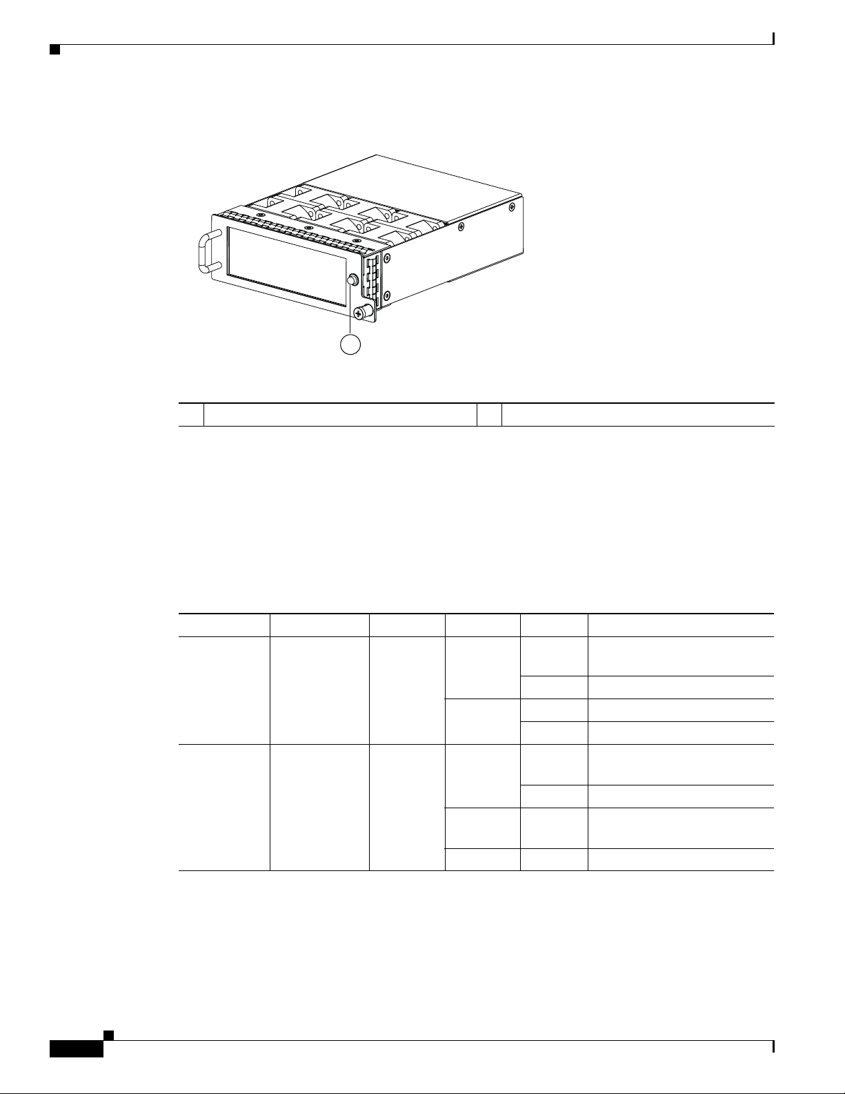
Cisco Nexus 5010 Switch
1
Send documentation comments to nx5000-docfeedback@cisco.com
Figure 2-36 Cisco Nexus 5010 Fan Module
1 Fan module LED
Chapter 2 Cisco Nexus 5000 Series Overview
The bicolor fan module LED indicates the fan tray health. Green indicates normal operation, while
amber indicates a fan failure.
LED Descriptions
Table 2-9 describes the LEDs for the Cisco Nexus 5010 switch.
Ta b l e 2-9 LEDs for the Cisco Nexus 5010 Switch
LED Location Function Color Status Description
Power LED Front of
Fan Tray Status
Chassis
Fan
trays (front)
Chassis
Power/
Health
Fan tray
heath
indicator
(multicolor)
Green Solid On System is and on operation
normally
Off Switch is powered off
Amber On Fault condition
Green Solid On
Amber Solid On
Fan tray operating
normally
Fan failure within the fan
tray
2-30
Cisco Nexus 5000 Series Hardware Installation Guide
OL-15902-01
Page 63

Chapter 2 Cisco Nexus 5000 Series Overview
Send documentation comments to nx5000-docfeedback@cisco.com
Table 2-9 LEDs for the Cisco Nexus 5010 Switch (continued)
LED Location Function Color Status Description
PSU Status
Indicators
GEM
Health Indicator
Power supply
(front)
Back of chassis
PSU Health
(multi color)
An indicator
to show
there is a
fault with
any one of
the GEMs
Cisco Nexus 5010 Switch
Green OFF No AC power to power supply
Solid On Power supply on and OK
Amber Solid On
Blinking AC present, 3.3 VSB on,
OFF Operating normally
Green On
Amber Solid on
Power supply failures, overvoltage,
overcurrent, overtemperature
PSU is off
GEM is operating
normally
A fault has occurred on
the GEM.
Port Level LEDs
There are 20 to 26 port activity LEds on the switch depending on whether the GEM is a Fibre Channel
or 10-Gigabit Ethernet module.
Ta b l e 2-10 Port Level LEDs
Link State LED State Notes
Link Down OFF —
POST failed on port AMBER blinking yellow —
Administrative disabled AMBER_ON
Link Up,
port in STP forwarding
state
Supported SFP Transceivers
The Cisco Nexus 5010 switch supports both SFP+ Ethernet transceivers and SFP Fibre Channel
transceivers.
This section includes the following topics:
• SFP+ Transceivers, page 2-32
Table 2-10 describes the behavior of the port LEDs.
Depending on the product you look at, the
LED could be off, or solid amber
GREEN_ON Blinks based on network activity
OL-15902-01
• SFP+ Copper Cables, page 2-32
• SFP Fiber Channel Transceivers, page 2-32
Cisco Nexus 5000 Series Hardware Installation Guide
2-31
Page 64

Cisco Nexus 5010 Switch
Send documentation comments to nx5000-docfeedback@cisco.com
SFP+ Transceivers
The enhanced Small-Form-Factor Pluggable (SFP+) 10-Gigabit Ethernet transceiver module is a
bidirectional device with a transmitter and receiver in the same physical package. See
a 20-pin connector on the electrical interface and duplex LC connector on the optical interface.The Cisco
Nexus 5010 switch supports the following SFP+ optical transceivers:
• SR
• DCR, SR-Lite (shorter reach than SR)
• LRM (for uplink only)
• LR (for uplink only)
Model Description
SFP-10G-SR 10-Gigabit Ethernet—Short range SFP+ module
SFP-10G-LR 10-Gigabit Ethernet—Long range SFP+ module
Chapter 2 Cisco Nexus 5000 Series Overview
Tabl e 2-11. It has
Ta b l e 2-11 SFP+ Transceivers
SFP+ Copper Cables
Copper cables are available for use with the 10-Gigabit Ethernet SFP+ module. SeeTable 2-12. The
cables come in the following lengths:
• 1m, 30AWG
• 3m, 28-30 AWG
• 5m, 26-28 AWG
Model Description
SFP-H10GB-CU1M 10GBASE-CU SFP+ cable (1 meters)
SFP-H10GB-CU3M 10GBASE-CU SFP+ cable (3 meters)
SFP-H10GB-CU5M 10GBASE-CU SFP+ cable (5 meters)
SFP Fiber Channel Transceivers
The Cisco Nexus 5010 switch supports the multimode 850nm 4Gbps SFP with 150m reach. See
Table 2-13.
Ta b l e 2-12 SFP+ Copper Cables
2-32
Ta b l e 2-13 SFP Fiber Channel Transceivers
Model Description
DS-SFP-FC4G-SW 4 Gbps Fibre Channel-SW SFP, LC
DS-SFP-FC4G-LW 4 Gbps Fibre Channel-LW SFP, LC, (10 km reach)
Cisco Nexus 5000 Series Hardware Installation Guide
OL-15902-01
Page 65

Send comments to n5kdocs@cisco.com
CHAPTER
3
Installing the Cisco Nexus 5500 Platform or 5000 Series Switch
This chapter describes how to install the Cisco Nexus 5500 Platform switch (Cisco Nexus 5548P), and
the Cisc Nexus 5000 Series switches. This chapter includes the following sections:
• Preparing for Installation, page 3-2
• Installing the Cisco Nexus 5548 Chassis in a Cabinet or Rack, page 3-5
• Grounding the System, page 3-13
• Grounding the Cisco Nexus 5548P Chassis, page 3-18
• Starting the Switch, page 3-21
• Removing and Installing Components, page 3-22
• Repacking the Cisco Nexus 5548P switch or the Cisco Nexus 5000 Series switch for Return
Shipment, page 3-31
Note Before you install, operate, or service the system, see the Regulatory Compliance and Safety Information
for the Cisco Nexus 5000 Family for important safety information.
Warning
Warning
IMPORTANT SAFETY INSTRUCTIONS
This warning symbol means danger. You are in a situation that could cause bodily injury. Before
you work on any equipment, be aware of the hazards involved with electrical circuitry and be
familiar with standard practices for preventing accidents. Use the statement number provided at
the end of each warning to locate its translation in the translated safety warnings that
accompanied this device.
Statement 1071
SAVE THESE INSTRUCTIONS
This unit is intended for installation in restricted access areas. A restricted access area can be
accessed only through the use of a special tool, lock and key, or other means of security.
Statement 1017
OL-15902-01
Cisco Nexus 5000 Series Hardware Installation Guide
3-1
Page 66

Preparing for Installation
Chapter 3 Installing the Cisco Nexus 5500 Platform or 5000 Series Switch
Send comments to n5kdocs@cisco.com
Warning
Note Each new switch requires a license. For information on licensing, see the CiscoNX-OS Licensing Guide.
Only trained and qualified personnel must be allowed to install, replace, or service
this equipment.
Statement 1030
Preparing for Installation
This section describes how to prepare the Cisco Nexus 5548P, the Cisco Nexus 5020, and the Cisco
Nexus 5010 switches for installation. This section includes the following topics:
• Installation Options, page 3-2
• Installation Guidelines, page 3-3
• Required Equipment, page 3-4
• Unpacking and Inspecting the Switch, page 3-4
Installation Options
The Cisco Nexus 5548P switch or the Cisco 5000 Series switch can be installed using the following
methods:
• In an open EIA rack, using the following items:
–
The rack-mount kit shipped with the switch
• In a perforated or solid-walled EIA cabinet, using:
–
The rack-mount kit shipped with the switch
For instructions on installing the Nexus 5548P switch using the rack-mount kit shipped with the switch,
see the
instructions on installing a Cisco Nexus 5000 Series switch using the rack-mount kit shipped with the
switch, see the "Installing the Cisco Nexus 5020 Chassis in a Cabinet or Rack" section on page 3-5.
“Installing the Cisco Nexus 5548 Chassis in a Cabinet or Rack” section on page 3-5. For
Airflow Considerations
Airflow through the Cisco Nexus 5548P switch or the Cisc Nexus 5000 Series switch is from front to
back. Air enters the chassis through the fan trays and power supplies mounted at the front of the chassis
and exits the chassis through perforations on the rear of the chassis. To ensure proper airflow, follow
these guidelines:
• Maintain ambient airflow throughout the data center to ensure normal operation.
• Consider the heat dissipation of all equipment when determining air-conditioning requirements.
When evaluating airflow requirements, take into consideration that hot air generated by equipment
at the bottom of the rack can be drawn in the intake ports of the equipment above.
3-2
Cisco Nexus 5000 Series Hardware Installation Guide
OL-15902-01
Page 67

Chapter 3 Installing the Cisco Nexus 5500 Platform or 5000 Series Switch
Send comments to n5kdocs@cisco.com
Chassis Weight
When lifting the system, follow these guidelines:
• Disconnect all power and external cables before lifting the system.
• Have two people to lift the system. The Cisco Nexus 5548P switch weighs 35 lb (15.88 kg).
• The Cisco Nexus 5020 switch weighs 50 lb (22.680 kg and the Cisco Nexus 5010 switch weighs 35
lb (15.876 kg)
• Ensure that your footing is solid and the weight of the system is evenly distributed between your
.
feet.
• Lift the system slowly, keeping your back straight. Lift with your legs, not with your back. Bend at
the knees, not at the waist.
Installation Guidelines
When installing the Cisco Nexus 5548P switch or the Cisco Nexus 5000 Series switch, follow these
guidelines:
• Plan your site configuration and prepare the site before installing the chassis. Appendix D, “Site
Planning and Maintenance Records,” lists the recommended site planning tasks.
• Record the information listed in Appendix D, “Site Planning and Maintenance Records,” as you
install and configure the switch.
Preparing for Installation
• Ensure that there is adequate space around the switch to allow for servicing the switch and for
adequate airflow (
• Ensure that the air-conditioning meets the heat dissipation requirements listed in Appendix B,
Appendix B, “Technical Specifications,” lists airflow requirements).
“Technical Specifications.”
• Ensure that the cabinet or rack meets the requirements listed in Appendix A, “Cabinet and Rack
Installation.”
Note Jumper power cords are available for use in a cabinet. See the “Jumper Power Cord” section on
page C-12.
• Ensure that the chassis is adequately grounded. If the switch is not mounted in a grounded rack, we
recommend connecting both the system ground on the chassis and the power supply ground to an
earth ground.
• Ensure that the site power meets the power requirements listed in Appendix B, “Technical
Specifications.” If available, you can use an uninterruptible power supply (UPS) to protect against
power failures.
Caution Avoid UPS types that use ferroresonant technology. These UPS types can become unstable
with systems such as the Cisco Nexus 5548P switch or the Cisco Nexus 5000 Series switch,
which can have substantial current draw fluctuations because of fluctuating data traffic
patterns.
OL-15902-01
• Ensure that circuits are sized according to local and national codes. For North America, the power
supply requires a 15-A or 20-A circuit.
Cisco Nexus 5000 Series Hardware Installation Guide
3-3
Page 68

Preparing for Installation
Send comments to n5kdocs@cisco.com
Caution To prevent loss of input power, ensure the total maximum loads on the circuits supplying
power to the switch are within the current ratings for the wiring and breakers.
• Use the following screw torques when installing the switch:
–
Captive screws: 4 in-lb
–
M3 screws: 4 in-lb
–
M4 screws: 12 in-lb
–
10-32 screws: 20 in-lb
–
12-24 screws: 30 in-lb
Required Equipment
Before beginning the installation, ensure that the following items are ready:
• Number 1 and number 2 Phillips screwdrivers with torque capability
Chapter 3 Installing the Cisco Nexus 5500 Platform or 5000 Series Switch
• 3/16-inch flat-blade screwdriver
• Tape measure and level
• ESD wrist strap or other grounding device
• Antistatic mat or antistatic foam
The following additional items (not found in the accessory kit) are required to ground the chassis:
• Grounding cable (6 AWG recommended), sized according to local and national installation
requirements; the required length depends on the proximity of the Cisco Nexus 5548P switch or the
Cisco Nexus 5000 Series switch to proper grounding facilities
• Crimping tool large enough to accommodate girth of lug
• Wire-stripping tool
Unpacking and Inspecting the Switch
Caution When handling switch components, wear an ESD strap and handle modules by the carrier edges only.
An ESD socket is provided on the chassis. For the ESD socket to be effective, the chassis must be
grounded through the power cable, the chassis ground, or the metal-to-metal contact with a grounded
rack.
3-4
Tip Keep the shipping container in case the chassis requires shipping in the future.
Note The switch is thoroughly inspected before shipment. If any damage occurred during transportation or
any items are missing, contact your customer service representative immediately.
Cisco Nexus 5000 Series Hardware Installation Guide
OL-15902-01
Page 69

Chapter 3 Installing the Cisco Nexus 5500 Platform or 5000 Series Switch
Send comments to n5kdocs@cisco.com
To inspect the shipment, follow these steps:
Step 1 Compare the shipment to the equipment list provided by your customer service representative and verify
that you have received all items, including the following:
• Print documentation
• Grounding lug kit
• Rack-mount kit
• ESD wrist strap
• Cables with connectors
• Any optional items ordered
Step 2 Check for damage and report any discrepancies or damage to your customer service representative. Have
the following information ready:
• Invoice number of shipper (see packing slip)
• Model and serial number of the damaged unit
• Description of damage
Installing the Cisco Nexus 5548 Chassis in a Cabinet or Rack
• Effect of damage on the installation
Installing the Cisco Nexus 5548 Chassis in a Cabinet or Rack
This section describes how to use the rack-mount kit provided with the switch to install the Cisco Nexus
5548 switch into a cabinet or rack that meets the requirements described in
Rack Installation.”
Caution If the rack is on wheels, ensure that the brakes are engaged or that the rack is otherwise stabilized.
Table 3-1 lists the items contained in the rack-mount kit provided with the switch.
Ta b l e 3-1 Cisco Nexus 5548 Switch Rack-Mount Kit
Quantity Part Description
2 Rack-mount brackets
12 M4x0.7 x 8-mm Phillips countersunk screws
2 Rack-mount guides
10 10-32 Rack Nuts
10 10-32 x 3/4-inch Phillips countersunk screws
2 Slider rails
(20 inch minimum to a 36 inch maximum
Appendix A, “Cabinet and
OL-15902-01
Cisco Nexus 5000 Series Hardware Installation Guide
3-5
Page 70

Installing the Cisco Nexus 5548 Chassis in a Cabinet or Rack
Send comments to n5kdocs@cisco.com
To install the switch in a cabinet or rack using the rack-mount kit provided with the switch, follow these
steps:
Step 1 Install the front rack-mount brackets as follows:
a. Position a front rack-mount bracket against the chassis and align the screw holes as shown in
Figure 3-1. Attach the front rack-mount bracket to the chassis with six of the M4 screws.
b. Repeat with the other front rack-mount bracket on the other side of the switch.
Figure 3-1 Attaching Front Rack-Mount Bracket to the Cisco Nexus 5548 Switch
Chapter 3 Installing the Cisco Nexus 5500 Platform or 5000 Series Switch
3
2
1
236713
1 Front rack-mount bracket 3 Slider rail
2 Rack-mount guides
Step 2 Install the rack-mount guides on the switch as follows:
a. Position one of the rack-mount brackets against the side of the switch and align the screw holes. See
Figure 3-1. Attach the bracket to the switch with two of the flat-head M4 screws.
b. Repeat with the other rack-mount bracket on the other side of the switch.
Step 3 Attach the slider rails to the rack as shown in Figure 3-2. Use two 12-24 screws or two 10-32 screws,
depending on the rack rail thread type. For racks with square holes, insert the 12-24 cage nuts in position
behind the mounting holes in the slider rails.
a. Repeat with the other slider rail on the other side of the rack.
b. Use the tape measure and level to verify that the rails are horizontal and at the same height.
3-6
Cisco Nexus 5000 Series Hardware Installation Guide
OL-15902-01
Page 71

Chapter 3 Installing the Cisco Nexus 5500 Platform or 5000 Series Switch
186412
Send comments to n5kdocs@cisco.com
Figure 3-2 Installing the Slider Rails
Installing the Cisco Nexus 5020 Chassis in a Cabinet or Rack
Step 4 Insert the switch into the rack as follows:
a. Using both hands, position the switch with the back of the switch between the front posts of the rack.
b. Align the two rack-mount guides on either side of the switch with the slider rails installed in the
rack. Slide the rack-mount glides onto the slider rails, and then gently slide the switch all the way
into the rack. If the switch does not slide easily, try realigning the rack-mount glides on the slider
rails.
Step 5 Stabilize the switch in the rack by attaching the front rack-mount brackets to the front rack-mounting
rails:
a. Insert two screws (12-24 or 10-32, depending on the rack type) through the cage nuts and the holes
in one of the front rack-mount brackets and into the threaded holes in the rack-mounting rail.
b. Repeat for the front rack-mount bracket on the other side of the switch.
Installing the Cisco Nexus 5020 Chassis in a Cabinet or Rack
This section describes how to use the rack-mount kit provided with the switch to install the Cisco Nexus
5020 switch into a cabinet or rack that meets the requirements described in
Rack Installation.” All Cisco Nexus 5020 switch switches use the same installation procedure.
Appendix A, “Cabinet and
OL-15902-01
Caution If the rack is on wheels, ensure that the brakes are engaged or that the rack is otherwise stabilized.
Table 3-2 lists the items contained in the rack-mount kit provided with the switch.
Cisco Nexus 5000 Series Hardware Installation Guide
3-7
Page 72

Installing the Cisco Nexus 5020 Chassis in a Cabinet or Rack
2 3
1
Send comments to n5kdocs@cisco.com
Ta b l e 3-2 Cisco Nexus 5020 Switch Rack-Mount Kit
Quantity Part Description
2 Rack-mount brackets
16 M4x0.7 x 8-mm Phillips countersunk screws
2 Rack-mount guides
12 10-32 Rack Nuts
12 10-32 x 3/4-inch Phillips countersunk screws
2 Slider rails
(22 inch minimum to a 36 inch maximum)
To install the switch in a cabinet or rack using the rack-mount kit provided with the switch, follow these
steps:
Step 1 Install the front rack-mount brackets as follows:
a. Position a front rack-mount bracket against the chassis and align the screw holes as shown in
Figure 3-3. Then attach the front rack-mount bracket to the chassis with six of the M4 screws.
b. Repeat with the other front rack-mount bracket on the other side of the switch.
Chapter 3 Installing the Cisco Nexus 5500 Platform or 5000 Series Switch
Figure 3-3 Attaching Front Rack-Mount Bracket to the Cisco Nexus 5020 switch
1 Front rack-mount bracket 3 Slider rail
2 Rack-mount guides
Step 2 Install the rack-mount guides on the switch as follows:
a. Position one of the rack-mount brackets against the side of the switch and align the screw holes as
shown in
b. Repeat with the other rack-mount bracket on the other side of the switch.
Figure 3-3. Then attach the bracket to the switch with two of the flat-head M4 screws.
3-8
Cisco Nexus 5000 Series Hardware Installation Guide
OL-15902-01
Page 73

Chapter 3 Installing the Cisco Nexus 5500 Platform or 5000 Series Switch
186412
Send comments to n5kdocs@cisco.com
Step 3 Attach the slider rails to the rack as shown in Figure 3-4. Use two 12-24 screws or two 10-32 screws,
depending on the rack rail thread type. For racks with square holes, insert the 12-24 cage nuts in position
behind the mounting holes in the slider rails.
a. Repeat with the other slider rail on the other side of the rack.
b. Use the tape measure and level to verify that the rails are horizontal and at the same height.
Figure 3-4 Installing the Slider Rails
Installing the Cisco Nexus 5020 Chassis in a Cabinet or Rack
Step 4 Insert the switch into the rack:
a. Using both hands, position the switch with the back of the switch between the front posts of the rack.
b. Align the two rack-mount guides on either side of the switch with the slider rails installed in the
rack. Slide the rack-mount glides onto the slider rails, and then gently slide the switch all the way
into the rack. See
Figure 3-5. If the switch does not slide easily, try realigning the rack-mount glides
on the slider rails.
OL-15902-01
Cisco Nexus 5000 Series Hardware Installation Guide
3-9
Page 74

Installing the Cisco Nexus 5020 Chassis in a Cabinet or Rack
186413
186414
Send comments to n5kdocs@cisco.com
Figure 3-5 Sliding the Chassis Into the Rack
Chapter 3 Installing the Cisco Nexus 5500 Platform or 5000 Series Switch
Step 5 Stabilize the switch in the rack by attaching the front rack-mount brackets to the front rack-mounting
rails:
a. Insert two screws (12-24 or 10-32, depending on rack type) through the cage nuts and the holes in
one of the front rack-mount brackets and into the threaded holes in the rack-mounting rail. See
Figure 3-6.
b. Repeat for the front rack-mount bracket on the other side of the switch.
Figure 3-6 Attaching the Switch to the Rack
3-10
Cisco Nexus 5000 Series Hardware Installation Guide
OL-15902-01
Page 75

Chapter 3 Installing the Cisco Nexus 5500 Platform or 5000 Series Switch
2
3
273161
1
Installing the Cisco Nexus 5010 Chassis in a Cabinet or Rack
Send comments to n5kdocs@cisco.com
Installing the Cisco Nexus 5010 Chassis in a Cabinet or Rack
This section describes how to use the rack-mount kit provided with the switch to install the Cisco Nexus
5010 switch into a cabinet or rack that meets the requirements described in
Rack Installation.” All Cisco Nexus 5000 switches use the same installation procedure.
Caution If the rack is on wheels, ensure that the brakes are engaged or that the rack is otherwise stabilized.
Table 3-2 lists the items contained in the rack-mount kit provided with the switch.
Ta b l e 3-3 Cisco Nexus 5010 Switch Rack-Mount Kit
Quantity Part Description
2 Rack-mount brackets
12 M4x0.7 x 8-mm Phillips countersunk screws
2 Rack-mount guides
10 10-32 Rack Nuts
10 10-32 x 3/4-inch Phillips countersunk screws
2 Slider rails
(21 inch minimum to a 33 inch maximum
Appendix A, “Cabinet and
To install the switch in a cabinet or rack using the rack-mount kit provided with the switch, follow these
steps:
Step 1 Install the front rack-mount brackets as follows:
a. Position a front rack-mount bracket against the chassis and align the screw holes as shown in
Figure 3-3. Then attach the front rack-mount bracket to the chassis with six of the M4 screws.
b. Repeat with the other front rack-mount bracket on the other side of the switch.
Figure 3-7 Attaching Front Rack-Mount Bracket to the Cisco Nexus 5010 switch
OL-15902-01
Cisco Nexus 5000 Series Hardware Installation Guide
3-11
Page 76

Installing the Cisco Nexus 5010 Chassis in a Cabinet or Rack
186412
Send comments to n5kdocs@cisco.com
1 Front rack-mount bracket 3 Slider rail
2 Rack-mount guides
Step 2 Install the rack-mount guides on the switch as follows:
a. Position one of the rack-mount brackets against the side of the switch and align the screw holes. This
procedure is the same as that for the Cisco Nexus 5020 switch. See
bracket to the switch with two of the flat-head M4 screws.
b. Repeat with the other rack-mount bracket on the other side of the switch.
Step 3 Attach the slider rails to the rack. This procedure is the same as that for the Cisco Nexus 5020 switch.
See
Figure 3-4. Use two 12-24 screws or two 10-32 screws, depending on the rack rail thread type. For
racks with square holes, insert the 12-24 cage nuts in position behind the mounting holes in the slider
rails.
a. Repeat with the other slider rail on the other side of the rack.
b. Use the tape measure and level to verify that the rails are horizontal and at the same height.
Chapter 3 Installing the Cisco Nexus 5500 Platform or 5000 Series Switch
Figure 3-3. Then attach the
Figure 3-8 Installing the Slider Rails
Step 4 Insert the switch into the rack:
a. Using both hands, position the switch with the back of the switch between the front posts of the rack.
b. Align the two rack-mount guides on either side of the switch with the slider rails installed in the
rack. Slide the rack-mount glides onto the slider rails, and then gently slide the switch all the way
into the rack. This procedure is the same as that for the Cisco Nexus 5020 switch. See
If the switch does not slide easily, try realigning the rack-mount glides on the slider rails.
Figure 3-5.
3-12
Cisco Nexus 5000 Series Hardware Installation Guide
OL-15902-01
Page 77

Chapter 3 Installing the Cisco Nexus 5500 Platform or 5000 Series Switch
Send comments to n5kdocs@cisco.com
Step 5 Stabilize the switch in the rack by attaching the front rack-mount brackets to the front rack-mounting
rails:
a. Insert two screws (12-24 or 10-32, depending on rack type) through the cage nuts and the holes in
one of the front rack-mount brackets and into the threaded holes in the rack-mounting rail. This
procedure is the same as that for the Cisco Nexus 5020 switch. See
b. Repeat for the front rack-mount bracket on the other side of the switch.
Grounding the System
This section describes the need for system grounding for the Cisco Nexus 5548P switch or the Cisco
Nexus 5000 Series switchand explains how to prevent damage from electrostatic discharge.
This section includes the following topics:
• Proper Grounding Practices, page 3-13
Grounding the System
Figure 3-6.
• Preventing Electrostatic Discharge Damage, page 3-15
• Establishing the System Ground, page 3-17
• Required Tools and Equipment, page 3-17
Proper Grounding Practices
Grounding is one of the most important parts of equipment installation. Proper grounding practices
ensure that the buildings and the installed equipment within them have low-impedance connections and
low-voltage differentials between chassis. When you properly ground systems during installation, you
reduce or prevent shock hazards, equipment damage due to transients, and data corruption.
lists some general grounding practice guidelines.
Table 3-4
OL-15902-01
Cisco Nexus 5000 Series Hardware Installation Guide
3-13
Page 78

Grounding the System
Chapter 3 Installing the Cisco Nexus 5500 Platform or 5000 Series Switch
Send comments to n5kdocs@cisco.com
Ta b l e 3-4 Proper Grounding Guidelines
Electromagnetic Noise
Environment
Commercial building is
subjected to direct lightning
strikes.
For example, some places in the
United States, such as Florida,
are subject to more lightning
strikes than other areas.
Commercial building is located
in an area where lightning
storms frequently occur but is
not subject to direct lightning
strikes.
Commercial building contains a
mix of information technology
equipment and industrial
equipment, such as welding.
Existing commercial building is
not subject to natural
environmental noise or
man-made industrial noise. This
building contains a standard
office environment. This
installation has a history of
malfunction due to
electromagnetic noise.
New commercial building is not
subject to natural environmental
noise or man-made industrial
noise. This building contains a
standard office environment.
Existing commercial building is
not subject to natural
environmental noise or
man-made industrial noise. This
building contains a standard
office environment.
Severity Level
High All lightning protection devices
High Best grounding
Medium to high Best grounding
Medium Determine source and cause of
Low Electromagnetic noise problems
Low Electromagnetic noise problems
Grounding Recommendations
must be installed in strict
accordance with manufacturer
recommendations. Conductors
carrying lightning current
should be spaced away from
power and data lines in
accordance with applicable
recommendations and codes.
Best grounding
recommendations must be
closely followed.
recommendations must be
closely followed.
recommendations must be
closely followed.
noise if possible, and mitigate as
closely as possible at the noise
source or reduce coupling from
the noise source to the affected
equipment. Best grounding
recommendations must be
closely followed.
are not anticipated, but
installing a grounding system in
a new building is often the least
expensive route and the best
way to plan for the future. Best
grounding recommendations
should be followed as closely as
possible.
are not anticipated, but
installing a grounding system is
always recommended. Best
grounding recommendations
should be followed as much as
possible.
3-14
Cisco Nexus 5000 Series Hardware Installation Guide
OL-15902-01
Page 79

Chapter 3 Installing the Cisco Nexus 5500 Platform or 5000 Series Switch
Send comments to n5kdocs@cisco.com
Note In all situations, grounding practices must comply with local National Electric Code (NEC)
requirements or local laws and regulations.
Note Always ensure that all of the modules are completely installed and that the captive installation screws
are fully tightened. In addition, ensure that all I/O cables and power cords are properly seated. These
practices are normal installation practices and must be followed in all installations.
Preventing Electrostatic Discharge Damage
Electrostatic discharge (ESD) damage, which can occur when modules or other FRUs are improperly
handled, results in intermittent or complete failures. Modules consist of printed circuit boards that are
fixed in metal carriers. Electromagnetic interference (EMI) shielding and connectors are integral
components of the carrier. Although the metal carrier helps to protect the board from ESD, always use
an ESD grounding strap when handling modules.
For preventing ESD damage, follow these guidelines:
Grounding the System
• Always use an ESD wrist strap and ensure that it makes maximum contact with bare skin.
• ESD grounding straps are available with banana plugs, metal spring clips, or alligator clips. All
chassis from the Cisco Nexus 5500 Platform or from the Cisco Nexus 5000 Series switches are
equipped with a banana plug connector (identified by the ground symbol next to the connector)
somewhere on the front panel. We recommend that you use a personal ESD grounding strap
equipped with a banana plug.
• If you choose to use the disposable ESD wrist strap supplied with most FRUs or an ESD wrist strap
equipped with an alligator clip, you must attach the system ground lug to the chassis in order to
provide a proper grounding point for the ESD wrist strap.
Note This system ground is also referred to as the network equipment building system (NEBS) ground.
• If your chassis does not have the system ground attached, you must install the system ground lug.
See the
“Establishing the System Ground” section on page 3-17 for installation instructions and
location of the chassis system ground pads.
Note You do not need to attach a supplemental system ground wire to the system ground lug; the lug provides
a direct path to the bare metal of the chassis.
After you install the system ground lug, follow these steps to correctly attach the ESD wrist strap:
OL-15902-01
Step 1 Attach the ESD wrist strap to bare skin as follows:
a. If you are using the ESD wrist strap supplied with the FRUs, open the wrist strap package and
unwrap the ESD wrist strap. Place the black conductive loop over your wrist and tighten the strap
so that it makes good contact with your bare skin.
b. If you are using an ESD wrist strap equipped with an alligator clip, open the package and remove
the ESD wrist strap. Locate the end of the wrist strap that attaches to your body and secure it to your
bare skin.
Cisco Nexus 5000 Series Hardware Installation Guide
3-15
Page 80

Grounding the System
2
1
3
4
5
Step 2 Grasp the spring or alligator clip on the ESD wrist strap and momentarily touch the clip to a bare metal
Step 3 Attach either the spring clip or the alligator clip to the ground lug screw as follows:
Chapter 3 Installing the Cisco Nexus 5500 Platform or 5000 Series Switch
Send comments to n5kdocs@cisco.com
spot (unpainted surface) on the rack. We recommend that you touch the clip to an unpainted rack rail so
that any built-up static charge is then safely dissipated to the entire rack.
a. If you are using the ESD wrist strap that is supplied with the FRUs, squeeze the spring clip jaws
open, position the spring clip to one side of the system ground lug screw head, and slide the spring
clip over the lug screw head so that the spring clip jaws close behind the lug screw head.
Note The spring clip jaws do not open wide enough to fit directly over the head of the lug screw or
the lug barrel.
b. If you are using an ESD wrist strap that is equipped with an alligator clip, attach the alligator clip
directly over the head of the system ground lug screw or to the system ground lug barrel.
To attach the ESD wrist strap to the system ground lug screw for the Cisco Nexus 5548 switch, you can
follow the same procedure that is used for Cisco Nexus 5000 switch.
Figure 3-9 Attaching the ESD Wrist Strap to the System Ground Lug Screw
3-16
1 ESD ground strap 3 Side view of grounding lug (clip slid behind
2 Clip and grounding lug 4 Clip installed (behind screw)
5 System ground connector
Cisco Nexus 5000 Series Hardware Installation Guide
screw)
OL-15902-01
Page 81

Chapter 3 Installing the Cisco Nexus 5500 Platform or 5000 Series Switch
Send comments to n5kdocs@cisco.com
In addition, follow these guidelines when handling modules:
• Handle carriers by available handles or edges only; avoid touching the printed circuit boards or
connectors.
• Place a removed component board-side-up on an antistatic surface or in a static-shielding container.
If you plan to return the component to the factory, immediately place it in a static-shielding
container.
• Never attempt to remove the printed circuit board from the metal carrier.
Caution For safety, periodically check the resistance value of the antistatic strap. The measurement should be
between 1 and 10 megohm (Mohm).
Establishing the System Ground
This section describes how to connect a system ground to the Cisco Nexus 5548P switch or or the Cisco
Nexus 5000 Series switch.
Grounding the System
Note This system ground is also referred to as the network equipment building system (NEBS) ground.
You must use the system (NEBS) ground on AC-powered systems if you are installing this equipment in
a U.S. or European Central Office.
The system (NEBS) ground provides additional grounding for EMI shielding requirements and
grounding for the low-voltage supplies (DC-DC converters) on the modules and is intended to satisfy
the Telcordia Technologies NEBS requirements for supplemental bonding and grounding connections.
You must observe the following system grounding guidelines for your chassis:
• You must install the system (NEBS) ground connection with any other rack or system power ground
connections that you make. The system ground connection is required if this equipment is installed
in a U.S. or European Central Office.
• You must connect both the system (NEBS) ground connection and the power supply ground
connection to an earth ground. The system (NEBS) ground connection is required if this equipment
is installed in a U.S. or European Central Office.
• You do not need to power down the chassis because the Cisco Nexus 5548 switch and the Cisco
Nexus 5020 switch are equipped with AC-input power supplies.
Required Tools and Equipment
To connect the system ground, you need the following tools and materials:
• Grounding lug—A two-hole standard barrel lug. This lug supports up to 6 AWG wire. Supplied as
part of accessory kit.
OL-15902-01
• Grounding screws—Two M4 x 8mm (metric) pan-head screws. These screws are supplied as part of
the accessory kit.
Cisco Nexus 5000 Series Hardware Installation Guide
3-17
Page 82

Chapter 3 Installing the Cisco Nexus 5500 Platform or 5000 Series Switch
Grounding the Cisco Nexus 5548P Chassis
Send comments to n5kdocs@cisco.com
• Grounding wire—Not supplied as part of accessory kit. The grounding wire should be sized
according to local and national installation requirements. Depending on the power supply and
system, a 12 AWG to 6 AWG copper conductor is required for U.S. installations. Commercially
available 6 AWG wire is recommended. The length of the grounding wire depends on the proximity
of the switch to proper grounding facilities.
• No. 1 Phillips screwdriver.
• Crimping tool to crimp the grounding wire to the grounding lug.
• Wire-stripping tool to remove the insulation from the grounding wire.
Grounding the Cisco Nexus 5548P Chassis
The chassis has a grounding pad with two threaded M4 holes for attaching a grounding lug. The location
of the system ground on the Cisco Nexus Cisco Nexus 5548P switch is identical to that on the Cisco
Nexus 5000 Series switch.
Note For the procedure on how to ground the Cisco Nexus 5000 Series switch chassis, see page x-x.
Warning
Caution We recommend grounding the chassis, even if the rack is already grounded.
Caution All power supplies must be grounded. The receptacles of the AC power cables used to provide power to
When installing or replacing the unit, the ground connection must always be made first and
disconnected last.
Statement 1046
the chassis must be the grounding type, and the grounding conductors should connect to protective earth
ground at the service equipment.
Warning
When installing or replacing the unit, the ground connection must always be made first and
disconnected last.
Statement 1046
Caution Grounding the chassis is required if you are using DC power supplies, even if the rack is already
grounded. A grounding pad with two threaded M4 holes is provided on the chassis for attaching a
grounding lug. The ground lug must be NRTL listed. In addition, the copper conductor (wires) must be
used and the copper conductor must comply with NEC code for ampacity.
3-18
To attach the grounding lug and cable to the chassis, follow these steps:
Step 1 Use a wire-stripping tool to remove approximately 0.75 inches (19 mm) of the covering from the end of
the grounding cable.
Step 2 Insert the stripped end of the grounding cable into the open end of the grounding lug.
Cisco Nexus 5000 Series Hardware Installation Guide
OL-15902-01
Page 83

Chapter 3 Installing the Cisco Nexus 5500 Platform or 5000 Series Switch
Grounding the Cisco Nexus 5000 Series Switch Chassis
Send comments to n5kdocs@cisco.com
Step 3 Use the crimping tool to secure the grounding cable in the grounding lug.
Step 4 Remove the adhesive label from the grounding pad on the chassis.
Step 5 Place the grounding lug against the grounding pad so that there is solid metal-to-metal contact, and insert
the two M4 screws with washers through the holes in the grounding lug and into the grounding pad.
Step 6 Ensure that the lug and cable do not interfere with other equipment.
Step 7 Prepare the other end of the grounding cable and connect it to an appropriate grounding point in your
site to ensure adequate earth ground.
Grounding the Cisco Nexus 5000 Series Switch Chassis
The chassis has a grounding pad with two threaded M4 holes for attaching a grounding lug. Figure 3-10
shows the system ground location on the Cisco Nexus 5020 switch. It is identical for the Cisco Nexus
5010 switch.
Warning
Caution We recommend grounding the chassis, even if the rack is already grounded.
Caution All power supplies must be grounded. The receptacles of the AC power cables used to provide power to
When installing or replacing the unit, the ground connection must always be made first and
disconnected last.
Statement 1046
the chassis must be the grounding type, and the grounding conductors should connect to protective earth
ground at the service equipment.
OL-15902-01
Cisco Nexus 5000 Series Hardware Installation Guide
3-19
Page 84

Grounding the Cisco Nexus 5000 Series Switch Chassis
186483
2
3
4
5
6
1
Send comments to n5kdocs@cisco.com
Figure 3-10 Location of System Ground on a Cisco Nexus 5000 Switch
Chapter 3 Installing the Cisco Nexus 5500 Platform or 5000 Series Switch
1 ESD socket (on switch) 4 Screws, M4, with square cone
washers
2 ESD plug 5 NRTL listed grounding lug
3 Grounding cable 6 Close-up of grounding pad on
switch
Warning
When installing or replacing the unit, the ground connection must always be made first and
disconnected last.
Statement 1046
Caution Grounding the chassis is required if you are using DC power supplies, even if the rack is already
grounded. A grounding pad with two threaded M4 holes is provided on the chassis for attaching a
grounding lug. The ground lug must be NRTL listed. In addition, the copper conductor (wires) must be
used and the copper conductor must comply with NEC code for ampacity.
To attach the grounding lug and cable to the chassis, follow these steps:
Step 1 Use a wire-stripping tool to remove approximately 0.75 inches (19 mm) of the covering from the end of
the grounding cable.
3-20
Step 2 Insert the stripped end of the grounding cable into the open end of the grounding lug.
Step 3 Use the crimping tool to secure the grounding cable in the grounding lug.
Cisco Nexus 5000 Series Hardware Installation Guide
OL-15902-01
Page 85

Chapter 3 Installing the Cisco Nexus 5500 Platform or 5000 Series Switch
Send comments to n5kdocs@cisco.com
Step 4 Remove the adhesive label from the grounding pad on the chassis.
Step 5 Place the grounding lug against the grounding pad so that there is solid metal-to-metal contact, and insert
the two M4 screws with washers through the holes in the grounding lug and into the grounding pad.
Step 6 Ensure that the lug and cable do not interfere with other equipment.
Step 7 Prepare the other end of the grounding cable and connect it to an appropriate grounding point in your
site to ensure adequate earth ground.
Step 8 site to ensure adequate earth ground.
Starting the Switch
This section provides instructions for powering up the Cisco Nexus 5548P switch or the Cisco Nexus
5000 Series switch and verifying component installation.
Note Do not connect the Ethernet port to the LAN until the initial switch configuration has been performed.
For instructions on configuring the switch, see the Cisco Nexus 5000 Series CLI Configuration Guide.
For instructions on connecting to the console port, see the
page 4-2.
Starting the Switch
“Connecting to the Console Port” section on
Warning
When installing or replacing the unit, the ground connection must always be made first and
disconnected last.
Statement 1046
To power up the switch and verify hardware operation, follow these steps:
Step 1 Verify that empty power supply slots have filler panels installed, the faceplates of all modules are flush
with the front of the chassis, and the captive screws of the power supplies, fan module, and all expansion
modules are tight.
Step 2 Verify that the power supply and the fan modules are installed.
Note Depending on the outlet receptacle on your power distribution unit, you may need the optional
jumper power cord to connect the switch to your outlet receptacle. See the
“Jumper Power Cord”
section on page C-12.
Step 3 Ensure that the switch is adequately grounded as described in the “Grounding the System” section on
page 3-13, and that the power cables are connected to outlets that have the required AC power voltages
(see the “Power Specifications” section on page B-3).
Step 4 Connect the power cable to an AC power source. The switch should power on as soon as you connect
the power cable.
Step 5 Listen for the fans; they should begin operating when the power cable is plugged in.
OL-15902-01
Cisco Nexus 5000 Series Hardware Installation Guide
3-21
Page 86

Removing and Installing Components
Send comments to n5kdocs@cisco.com
Step 6 After the switch boots, verify that the LED operation is as follows:
• Fan module—Status LED is green.
• Power supply—Status LED is green.
• After initialization, the system status LED is green, indicating that all chassis environmental
monitors are reporting that the system is operational. If this LED is orange or red, then one or more
environmental monitor is reporting a problem.
• The Link LEDs for the Ethernet connector should not be on unless the cable is connected.
Note The link LEDs for the Fibre Channel ports remain yellow until the ports are enabled, and the
LED for the Ethernet connector port remains off until the port is connected.
Step 7 Try removing and reinstalling a component that is not operating correctly. If it still does not operate
correctly, contact your customer service representative for a replacement.
Note If you purchased this product through a Cisco reseller, contact the reseller directly for technical
support. If you purchased this product directly from Cisco, contact Cisco Technical Support at
this URL: http://www.cisco.com/warp/public/687/Directory/DirTAC.shtml.
Chapter 3 Installing the Cisco Nexus 5500 Platform or 5000 Series Switch
Step 8 Verify that the system software has booted and the switch has initialized without error messages.
If any problems occur, see Appendix E, “Troubleshooting Hardware Components”. If you cannot resolve
an issue, contact your customer service representative.
Step 9 Complete the worksheets provided in Appendix D, “Site Planning and Maintenance Records” for future
reference.
Note A setup utility automatically launches the first time you access the switch and guides you through the
basic configuration. For instructions on how to configure the switch and check module connectivity, see
the Cisco Nexus 5000 Series CLI Configuration Guide or the Cisco Nexus 5000 Series Fabric Manager
Configuration Guide.
Removing and Installing Components
This section describes how to remove and install components for the Cisco Nexus 5548P switch or the Cisco
Nexus 5000 Series switch.
This section includes the following topics:
• Removing and Installing Expansion Modules, page 3-23
• Removing and Installing Power Supplies, page 3-26
3-22
• Removing and Installing the Fan Module, page 3-28
• Removing the Cisco Nexus 5548P switch or the Cisco Nexus 5000 Series Switch, page 3-31
Cisco Nexus 5000 Series Hardware Installation Guide
OL-15902-01
Page 87

Chapter 3 Installing the Cisco Nexus 5500 Platform or 5000 Series Switch
Send comments to n5kdocs@cisco.com
Caution To prevent ESD damage, wear grounding wrist straps during these procedures and handle modules by
the carrier edges only.
Removing and Installing Expansion Modules
Caution To prevent ESD damage, wear grounding wrist straps during these procedures and handle expansion
modules by the carrier edges only.
Install the switch in the rack before installing expansion modules. For information about installing the
chassis, see the
the Installing the Cisco Nexus 5020 Chassis in a Cabinet or Rack, page 3-7.
This section includes the following topics:
• Installing an Expansion Module in the Cisco Nexus 5548 Switch, page 3-23
• Removing an Expansion Module, page 3-26
“Installing the Cisco Nexus 5548 Chassis in a Cabinet or Rack” section on page 3-5 or
Removing and Installing Components
Installing an Expansion Module in the Cisco Nexus 5548 Switch
To install an expansion module in the Cisco Nexus5548P switch chassis, follow these steps:
Step 1 Grasp the handle of the module and place your other hand under the module to support it.
Step 2 Gently slide the module into the opening until you cannot push it any further.
Step 3 Tighten the captive screw on the front of the module.
Figure 3-11 shows the positioning of an expansion module in the Cisco Nexus5548P switch chassis.
OL-15902-01
Cisco Nexus 5000 Series Hardware Installation Guide
3-23
Page 88

Removing and Installing Components
236714
Send comments to n5kdocs@cisco.com
Figure 3-11 Positioning the Module in the Cisco Nexus 5548 Chassis
Chapter 3 Installing the Cisco Nexus 5500 Platform or 5000 Series Switch
Installing an Expansion Module in the Cisco Nexus 5000 Series Chassis
To install an expansion module in the Cisco Nexus5000 Series chassis, follow these steps:
Step 1 Grasp the handle of the module and place your other hand under the module to support it.
Step 2 Gently slide the module into the opening until you cannot push it any further.
Step 3 Tighten the captive screw on the front of the module.
Figure 3-11 shows the positioning of an expansion module in the Cisco Nexus 5020 chassis.
3-24
Cisco Nexus 5000 Series Hardware Installation Guide
OL-15902-01
Page 89

Chapter 3 Installing the Cisco Nexus 5500 Platform or 5000 Series Switch
Send comments to n5kdocs@cisco.com
Figure 3-12 Positioning the Module in the Cisco Nexus 5020 Chassis
Removing and Installing Components
Figure 3-13 shows the positioning of an expansion module in the 5010 chassis.
Figure 3-13 Positioning the Module in the Cisco Nexus 5010 Chassis
273162
OL-15902-01
Cisco Nexus 5000 Series Hardware Installation Guide
3-25
Page 90

Chapter 3 Installing the Cisco Nexus 5500 Platform or 5000 Series Switch
Removing and Installing Components
Send comments to n5kdocs@cisco.com
Removing an Expansion Module
To remove an expansion module from the Cisco Nexus 5548P switch or the Cisco Nexus 5000 Series
switch chassis, follow these steps:
Step 1 Disconnect any network interface cables attached to the module.
Step 2 Loosen the captive screw on the module.
Step 3 Remove the module from the chassis by grasping the handle on the right side of the module and sliding
the module part of the way out of the slot. Place your other hand under the module to support the weight
of it. Do not touch the module circuitry.
Step 4 Place the module on an antistatic mat or antistatic foam if not immediately reinstalling it in another slot.
Step 5 Install a filler panel to keep dust out of the chassis and maintain consistent airflow if the slot will remain
empty.
Removing and Installing Power Supplies
The Cisco Nexus 5548P switch or the Cisco Nexus 5000 Series switsh supports two front-end power
supplies, but it may be used with one power supply.
This section includes the following topics:
• Removing a Power Supply, page 3-26
• Installing a Power Supply, page 3-28
Note You can replace a faulty power supply while the system is operating provided the other power supply is
functioning.
Removing a Power Supply
Caution If you are using the Cisco Nexus 5548P switch or the Cisco Nexus 5000 Series switch with one power
supply, removing the power supply will cause the switch to shut down. If you are using two power
supplies and you remove one of them, the switch will continue to operate.
To remove a power supply, follow these steps:
Step 1 Grasp the power supply handle with your left hand.
Step 2 Push against the release latch with your left thumb and slide the power supply out of the chassis. See
Figure 3-14 to remove a power supply for the Cisco Nexus 5548P switch. To remove a power supply
from the Cisco Nexus 5020 switch, see figure .To remove a power supply from the Cisco Nexus 5010
switch, see figure
3-26
Step 3 Place your right hand under the power supply to support it while you slide it out of the chassis.
Cisco Nexus 5000 Series Hardware Installation Guide
OL-15902-01
Page 91

Chapter 3 Installing the Cisco Nexus 5500 Platform or 5000 Series Switch
Send comments to n5kdocs@cisco.com
Step 4 Install a blank power supply filler panel if the power supply bay is to remain empty.
Figure 3-14 Removing the Power Supply for the Cisco Nexus 5548 switch
Removing and Installing Components
236715
Figure 3-15 Removing the Power Supply for the Cisco Nexus 5020 switch
Figure 3-16 Removing the Power Supply for the 5010
OL-15902-01
Cisco Nexus 5000 Series Hardware Installation Guide
3-27
Page 92

Removing and Installing Components
273163
Installing a Power Supply
To install a power supply Cisco Nexus 5548P switch or the Cisco Nexus 5000 Series switch, follow these
steps:
Chapter 3 Installing the Cisco Nexus 5500 Platform or 5000 Series Switch
Send comments to n5kdocs@cisco.com
Step 1 Ensure that the system (earth) ground connection has been made. For ground connection instructions,
see the
Step 2 If the power supply bay has a filler panel, press the latches on the sides of the filler panel, and then slide
“Grounding the System” section on page 3-13.
it out of the power supply bay.
Step 3 Hold the power supply by the handle and position it so that the release latch is on the right, and then slide
it into the power supply bay, ensuring that the power supply is fully seated in the bay.
Step 4 Plug the power cable into the AC inlet connector at the rear of the chassis.
Note Depending on the outlet receptacle on your power distribution unit, you may need the optional
jumper power cord to connect the Cisco Nexus 5548 switch to your outlet receptacle. See the
“Jumper Power Cord” section on page C-12.
Step 5 Connect the other end of the power cable to an AC power source.
Caution In a system with dual power supplies, connect each power supply to a separate power source.
In case of a power source failure, the second source will most likely still be available.
Step 6 Verify the power supply operation by checking that the power supply LED is green.
Removing and Installing the Fan Module
The fan module is designed to be removed and replaced while the system is operating without presenting
an electrical hazard or damage to the system, provided the replacement is performed promptly.
Cisco Nexus 5000 Series Hardware Installation Guide
3-28
OL-15902-01
Page 93

Chapter 3 Installing the Cisco Nexus 5500 Platform or 5000 Series Switch
236716
186596
Send comments to n5kdocs@cisco.com
This section includes the following topics:
• Installing a Fan Module, page 3-29
• Removing a Fan Module, page 3-30
Installing a Fan Module
To install a fan module, follow these steps:
Step 1 Hold the fan module with the LED at the bottom.
Step 2 Place the fan module into the front chassis cavity so it rests on the chassis, and then push the fan module
into the chassis as far as it can go and the captive screw makes contact with the chassis, and tighten the
captive screw. See
Figure 3-17 Fan Module for the Cisco Nexus 5548 Switch
Removing and Installing Components
OL-15902-01
Figure 3-18 Fan Module for the Cisco Nexus 5020 switch
Cisco Nexus 5000 Series Hardware Installation Guide
3-29
Page 94

Removing and Installing Components
Send comments to n5kdocs@cisco.com
Figure 3-19shows a fan module partially installed in the Cisco Nexus 5010 switch.
Figure 3-19 Fan Module partially installed for the Cisco Nexus 5010 switch
Chapter 3 Installing the Cisco Nexus 5500 Platform or 5000 Series Switch
273164
Step 3 Listen for the fans if the switch is powered on. You should immediately hear them operating. If you do
not hear them, ensure that the fan module is inserted completely in the chassis and the faceplate is flush
with the outside surface of the chassis.
Step 4 Verify that the LED is green. If the LED is not green, one or more fans are faulty. If this occurs, contact
your customer service representative for a replacement part.
Note If you purchased this product through a Cisco reseller, contact the reseller directly for technical support.
If you purchased this product directly from Cisco, contact Cisco Technical Support at this URL:
http://www.cisco.com/warp/public/687/Directory/DirTAC.shtml.
Removing a Fan Module
Warning
Step 1 Loosen the captive screws on the fan module by turning them counterclockwise, using a flat-blade or
Step 2 Grasp the handle of fan module and pull it outward.
Step 3 Pull the fan module clear of the chassis.
When removing the fan tray, keep your hands and fingers away from the spinning fan blades. Let
the fan blades completely stop before you remove the fan tray.
To remove a fan module, follow these steps:
number
2 Phillips screwdriver if required.
Statement 258
3-30
Cisco Nexus 5000 Series Hardware Installation Guide
OL-15902-01
Page 95

Chapter 3 Installing the Cisco Nexus 5500 Platform or 5000 Series Switch
Repacking the Cisco Nexus 5548P switch or the Cisco Nexus 5000 Series switch for Return Shipment
Send comments to n5kdocs@cisco.com
Removing the Cisco Nexus 5548P switch or the Cisco Nexus 5000 Series Switch
Caution The slider rail and front rack-mount brackets do not have a stop mechanism when sliding in and out. If
the front of the chassis is unfastened from the rack and the chassis slides forward on the slider rails, it
may slip off the end of the rails and fall out of the rack.
To remove the Cisco Nexus 5548P switch or the Cisco Nexus 5000 Series switch from a rack, follow
these steps:
Step 1 Ensure that the weight of the switch is fully supported and that the switch is being held by another
person.
Step 2 Disconnect the power cord and the console cables.
Step 3 Disconnect all cables that are connected to SFP+ transceivers.
Step 4 Remove the screws fastening the front rack-mount brackets to the mounting rails.
Step 5 Gently slide the switch towards you, off of the slider rails and out of the rack.
Repacking the Cisco Nexus 5548P switch or the Cisco Nexus
5000 Series switch for Return Shipment
If you need to return the switch, remove the switch from the rack by following the steps in Removing
the Cisco Nexus 5548P switch or the Cisco Nexus 5000 Series Switch, page 3-31, and repack it for
shipment. If possible, use the original packing materials and container to repack the switch. Contact your
Cisco customer service representative to arrange for return shipment to Cisco.
OL-15902-01
Cisco Nexus 5000 Series Hardware Installation Guide
3-31
Page 96

Chapter 3 Installing the Cisco Nexus 5500 Platform or 5000 Series Switch
Repacking the Cisco Nexus 5548P switch or the Cisco Nexus 5000 Series switch for Return Shipment
Send comments to n5kdocs@cisco.com
3-32
Cisco Nexus 5000 Series Hardware Installation Guide
OL-15902-01
Page 97

Send documentation comments to nexus5kdocs@cisco.com
CHAPTER
4
Connecting the Switch
The Cisco Nexus 5500 Platform switches and Cisco Nexus 5500 Series switches provide the following
types of ports:
• Console port —An RS-232 port that you can use to create a local management connection.
• Ethernet ports, both encrypted and unencrypted—These ports can be used to connect to a LAN.
• Fibre Channel ports—These ports can be used to connect to a SAN.
Caution When running power and data cables in overhead or subfloor cable trays, we strongly recommend that
power cables and other potential noise sources must be located as far away as practical from network
cabling that terminates on Cisco equipment. In situations where long parallel cable runs cannot be
separated by at least 3.3 ft (1
in a grounded metallic conduit.
This chapter includes the following sections:
m), we recommend shielding any potential noise sources by housing them
• Preparing for Network Connections, page 4-2
• Connecting to the Console Port, page 4-2
• Connecting to the Ethernet Connector Port, page 4-3
• Connecting to an Ethernet Port, page 4-4
• Connecting to a Fibre Channel Port, page 4-7
OL-15902-01
Cisco Nexus 5000 Series Hardware Installation Guide
4-1
Page 98

Preparing for Network Connections
186705
Send documentation comments to nexus5kdocs@cisco.com
Preparing for Network Connections
When preparing your site for network connections to the Cisco Nexus 5500 Patform switch or Cisco
Nexus 5000 Series switch, consider the following for each type of interface, and gather all the required
equipment before connecting the ports:
• Cabling required for each interface type
• Distance limitations for each signal type
• Additional interface equipment required
Connecting to the Console Port
Note This section applies to the Cisco Nexus 5500 Patform switches and the Cisco Nexus 5000 Series
switches.
The console port is an RS-232 port with an RJ-45 interface. (See Figure 4-1.) The console port is an
asynchronous (async) serial port; any device connected to this port must be capable of asynchronous
transmission.
Chapter 4 Connecting the Switch
We recommend using this port to create a local management connection to set the IP address and other
initial configuration settings before connecting the switch to the network for the first time.
Caution The console port can be used to connect to a modem. If you do not connect it to a modem, connect it
either before powering the switch on or after the switch has completed the boot process.
Figure 4-1 shows how to connect to the console port on the Cisco Nexus 5000 Series switch. The process
is identical for the Cisco Nexus 5500 switch.
Figure 4-1 Connecting to the Console Port on a Cisco Nexus 5000 Series Switch
4-2
Cisco Nexus 5000 Series Hardware Installation Guide
OL-15902-01
Page 99

Chapter 4 Connecting the Switch
Send documentation comments to nexus5kdocs@cisco.com
You can use the console port to perform the following:
• Configure the Cisco Nexus 5500 Platform switch or Cisco Nexus 5000 Series switch from the CLI.
• Monitor network statistics and errors.
• Configure SNMP agent parameters.
• Download software updates.
Note To connect the console port to a computer terminal, the computer must support VT100 terminal
emulation. The terminal emulation software (frequently an application such as HyperTerminal or
Procomm Plus) makes communication between the Cisco Nexus 5500 Platform switch or Cisco Nexus
5000 Series switch and a computer possible during setup and configuration.
To connect the console port to a computer terminal, follow these steps:
Step 1 Configure the terminal emulator program to match the following default port characteristics: 9600 baud,
8 data bits, 1 stop bit, no parity.
Step 2 Connect the RJ-45 connector of the console cable to the console port (see Figure 4-1) and the DB-9
connector to the computer serial port.
Connecting to the Ethernet Connector Port
Note For configuration instructions, see the appropriate Cisco Nexus 5000 Series CLI Configuration
Guide.
Connecting to the Ethernet Connector Port
Note This section applies to the Cisco Nexus 5500 Patform switches and the Cisco Nexus 5000 Series
switches.
Caution To prevent an IP address conflict, do not connect the management port to the network until the initial
configuration is complete. For configuration instructions, see the Cisco Nexus 5000 Series CLI
Configuration Guide.
This section describes how to to connect the Ethernet connector port to an external hub, switch, or router.
The Ethernet connector port has an RJ-45 interface. To connect the Ethernet connector port to an external
hub, switch, or router, follow these steps:
Step 1 Connect the appropriate modular cable to the Ethernet connector port:
• Use modular, RJ-45, straight-through UTP cables to connect the Ethernet connector port to an
Ethernet switch port or hub.
OL-15902-01
• Use a cross-over cable to connect to a router interface.
Cisco Nexus 5000 Series Hardware Installation Guide
4-3
Page 100

Connecting to an Ethernet Port
Send documentation comments to nexus5kdocs@cisco.com
Step 2 Connect the other end of the cable to the device.
Connecting to an Ethernet Port
Use an SFP+ transceiver to connect to an Ethernet port, as described in this section.
Removing and Installing SFP+ Transceivers
Caution Excessively removing and installing an SFP transceiver can shorten its life. Do not remove and insert
SFP transceivers more often unless it is absolutely necessary. We recommend disconnecting cables
before installing or removing SFP transceivers to prevent damage to the cable or transceiver.
This section includes the following topics:
• Installing an SFP+ Transceiver, page 4-4
Chapter 4 Connecting the Switch
• Removing an SFP+ Transceiver, page 4-5r
Installing an SFP+ Transceiver
To install an SFP+ transceiver, follow these steps:
Step 1 Attach an ESD-preventive wrist strap and follow its instructions for use.
Step 2 Remove the dust cover from the port cage.
Step 3 Remove the dust cover from the port end of the transceiver.
Step 4 Insert the transceiver into the port:
• If the transceiver has a Mylar tab, position the transceiver with the tab on the bottom, and then gently
insert the transceiver into the port until it clicks into place.
• If the transceiver has a bale clasp, position the transceiver with the clasp on the bottom, close the
clasp by pushing it up over the transceiver, and then gently insert the transceiver into the port until
it clicks into place.
Caution If the transceiver does not install easily, ensure that it is correctly positioned and the tab or
clasp are in the correct position before continuing.
4-4
Note If you cannot install the cable into the transceiver, insert or leave the dust plug in the cable end
of the transceiver.
Cisco Nexus 5000 Series Hardware Installation Guide
OL-15902-01
 Loading...