

Page 1

Catalyst 4948E and Catalyst 4948E-F
Switch Installation Guide
January 2011
Americas Headquarters
Cisco Systems, Inc.
170 West Tasman Drive
San Jose, CA 95134-1706
USA
http://www.cisco.com
Tel: 408 526-4000
800 553-NETS (6387)
Fax: 408 527-0883
Text Part Number: OL-21561-02
Page 2

THE SPECIFICATIONS AND INFORMATION REGARDING THE PRODUCTS IN THIS MANUAL ARE SUBJECT TO CHANGE WITHOUT NOTICE. ALL
STATEMENTS, INFORMATION, AND RECOMMENDATIONS IN THIS MANUAL ARE BELIEVED TO BE ACCURATE BUT ARE PRESENTED WITHOUT
WARRANTY OF ANY KIND, EXPRESS OR IMPLIED. USERS MUST TAKE FULL RESPONSIBILITY FOR THEIR APPLICATION OF ANY PRODUCTS.
THE SOFTWARE LICENSE AND LIMITED WARRANTY FOR THE ACCOMPANYING PRODUCT ARE SET FORTH IN THE INFORMATION PACKET THAT
SHIPPED WITH THE PRODUCT AND ARE INCORPORATED HEREIN BY THIS REFERENCE. IF YOU ARE UNABLE TO LOCATE THE SOFTWARE LICENSE
OR LIMITED WARRANTY, CONTACT YOUR CISCO REPRESENTATIVE FOR A COPY.
The following information is for FCC compliance of Class A devices: This equipment has been tested and found to comply with the limits for a Class A digital device, pursuant
to part 15 of the FCC rules. These limits are designed to provide reasonable protection against harmful interference when the equipment is operated in a commercial
environment. This equipment generates, uses, and can radiate radio-frequency energy and, if not installed and used in accordance with the instruction manual, may cause
harmful interference to radio communications. Operation of this equipment in a residential area is likely to cause harmful interference, in which case users will be required
to correct the interference at their own expense.
The following information is for FCC compliance of Class B devices: The equipment described in this manual generates and may radiate radio-frequency energy. If it is not
installed in accordance with Cisco’s installation instructions, it may cause interference with radio and television reception. This equipment has been tested and found to
comply with the limits for a Class B digital device in accordance with the specifications in part 15 of the FCC rules. These specifications are designed to provide reasonable
protection against such interference in a residential installation. However, there is no guarantee that interference will not occur in a particular installation.
Modifying the equipment without Cisco’s written authorization may result in the equipment no longer complying with FCC requirements for Class A or Class B digital
devices. In that event, your right to use the equipment may be limited by FCC regulations, and you may be required to correct any interference to radio or television
communications at your own expense.
You can determine whether your equipment is causing interference by turning it off. If the interference stops, it was probably caused by the Cisco equipment or one of its
peripheral devices. If the equipment causes interference to radio or television reception, try to correct the interference by using one or more of the following measures:
• Turn the television or radio antenna until the interference stops.
• Move the equipment to one side or the other of the television or radio.
• Move the equipment farther away from the television or radio.
• Plug the equipment into an outlet that is on a different circuit from the television or radio. (That is, make certain the equipment and the television or radio are on circuits
controlled by different circuit breakers or fuses.)
Modifications to this product not authorized by Cisco Systems, Inc. could void the FCC approval and negate your authority to operate the product.
The Cisco implementation of TCP header compression is an adaptation of a program developed by the University of California, Berkeley (UCB) as part of UCB’s public
domain version of the UNIX operating system. All rights reserved. Copyright © 1981, Regents of the University of California.
NOTWITHSTANDING ANY OTHER WARRANTY HEREIN, ALL DOCUMENT FILES AND SOFTWARE OF THESE SUPPLIERS ARE PROVIDED “AS IS” WITH
ALL FAULTS. CISCO AND THE ABOVE-NAMED SUPPLIERS DISCLAIM ALL WARRANTIES, EXPRESSED OR
LIMITATION, THOSE OF MERCHANTABILITY, FITNESS FOR A PARTICULAR PURPOSE AND NONINFRINGEMENT OR ARISING FROM A COURSE OF
DEALING, USAGE, OR TRADE PRACTICE.
IN NO EVENT SHALL CISCO OR ITS SUPPLIERS BE LIABLE FOR ANY INDIRECT, SPECIAL, CONSEQUENTIAL, OR INCIDENTAL DAMAGES, INCLUDING,
WITHOUT LIMITATION, LOST PROFITS OR LOSS OR DAMAGE TO DATA ARISING OUT OF THE USE OR INABILITY TO USE THIS MANUAL, EVEN IF CISCO
OR ITS SUPPLIERS HAVE BEEN ADVISED OF THE POSSIBILITY OF SUCH DAMAGES.
Cisco and the Cisco Logo are trademarks of Cisco Systems, Inc. and/or its affiliates in the U.S. and other countries. A listing of Cisco's trademarks can be found at
www.cisco.com/go/trademarks. Third party trademarks mentioned are the property of their respective owners. The use of the word partner does not imply a partnership
relationship between Cisco and any other company. (1005R)
Catalyst 4948E and Catalyst 4948E-F Switch Installation Guide
© 2010–2011 Cisco Systems, Inc. All rights reserved.
IMPLIED, INCLUDING, WITHOUT
Page 3

CONTENTS
Preface ix
Audience i-ix
Organization i-ix
Related Documentation i-x
Command Syntax Conventions i-x
Statement 1071—Warning Definition i-xi
Obtaining Documentation and Submitting a Service Request i-xvi
CHAPTER
CHAPTER
1 Product Overview 1-1
Features 1-3
Physical and Environmental Specifications 1-7
Fan Tray 1-8
Catalyst 4948E Fan Tray (WS-X4993=) 1-8
Catalyst 4948E-F Fan Tray (WS-X4993-F=) 1-9
Front Panel LEDs 1-11
2 Preparing for Installation 2-1
Safety 2-1
Site Requirements 2-2
Rack-Mounting Guidelines 2-2
Temperature 2-3
Air Flow 2-4
Humidity 2-5
Altitude 2-5
Dust and Particulates 2-5
Corrosion 2-6
Electromagnetic and Radio Frequency Interference 2-6
Shock and Vibration 2-7
OL-21561-02
Power Source Interruptions 2-7
System Grounding 2-7
Maintaining Safety with Electricity 2-9
Preventing Electrostatic Discharge Damage 2-10
Power Requirements 2-11
Catalyst 4948E and Catalyst 4948E-F Switch Installation Guide
iii
Page 4

Contents
Power Connection Guidelines for AC-Powered Systems 2-12
Power Connection Guidelines for DC-Powered Systems 2-12
Cabling Requirements 2-13
Site Preparation Checklist 2-13
CHAPTER
3 Installing the Switch 3-1
Preparing to Install the Chassis 3-1
Warnings 3-2
Verifying Package Contents 3-4
Required Tools 3-4
Lifting the Chassis Safely 3-5
Rack-Mounting the Chassis 3-5
Attaching the Rack-Mount Brackets to the Chassis 3-6
Installing the Chassis in the Rack 3-7
Installing the Cable Guide (Optional) 3-8
Installing the Catalyst 4948E-F Switch Chassis with the Optional Panduit Air Duct Kit 3-9
Installing the System Ground 3-10
Connecting Power to the Switch 3-12
Connecting AC Source Power to the Switch 3-12
Connecting DC Source Power to the Switch 3-13
Attaching the Interface Cables 3-15
Connecting to the Downlink Ports 3-16
Installing Uplink Port Transceivers and Cables 3-16
Connecting to the Ethernet Management Port 3-20
Connecting to the Console Port 3-20
CHAPTER
iv
Powering Up the Switch 3-21
Starting the Terminal-Emulation Software 3-21
Powering Up the Switch 3-21
4 Removal and Replacement Procedures 4-1
Removing and Installing the DC-Input Power Supply 4-2
Required Tools 4-2
Removing the DC-Input Power Supply 4-2
Installing the DC-Input Power Supply 4-5
Removing and Installing the AC-Input Power Supply 4-8
Required Tools 4-8
Removing the AC-Input Power Supply 4-8
Installing the AC-Input Power Supply 4-9
Catalyst 4948E and Catalyst 4948E-F Switch Installation Guide
OL-21561-02
Page 5

Removing and Installing the Fan Tray 4-10
Required Tools 4-10
Removing the Fan Tray 4-10
Installing the Fan Tray 4-11
Contents
APPENDIX
APPENDIX
A Power Supply Specifications A-1
300 W AC-Input Power Supply (PWR-C49E-300AC-R) A-1
300 W AC-Input Power Supply (PWR-C49E-300AC-F) A-5
300 W AC-Input Power Supply Power Cords A-8
300 W DC-Input Power Supply (PWR-C49-300DC) A-12
B Transceiver, Chassis Connectors, and Cable and Adapter Specifications B-1
Transceiver Support for Uplink Ports B-1
1-GB SFP Transceivers B-1
CWDM SFP Transceivers B-5
DWDM SFP Transceivers B-7
10-GB SFP+ Transceivers B-9
Console Port B-11
Ethernet Management Port B-12
Cables and Adapters B-12
Rollover Cable B-12
Rollover Cable RJ-45 to DB-9 Adapter (For Connecting to a PC) B-13
APPENDIX
APPENDIX
OL-21561-02
C Troubleshooting the Installation C-1
Getting Started C-2
Problem Solving to the System Component Level C-2
Identifying Startup Problems C-2
LED Readings C-3
Troubleshooting the Power Supply C-4
Contacting Customer Service C-4
D Regulatory Compliance and Safety Information D-1
Translated Safety Warnings D-2
Statement 17—Overtemperature Warning D-2
Statement 37—Restricted Area Warning D-3
Statement 39—Grounded Equipment Warning D-4
Statement 43—Jewelry Removal Warning D-5
Statement 48—Stacking the Chassis Warning D-8
Catalyst 4948E and Catalyst 4948E-F Switch Installation Guide
v
Page 6

Contents
Statement 171—Ethernet Cable Shielding in Offices D-9
Statement 258—Fan Tray Removal Warning D-10
Statement 322—DC Power Off Warning D-11
Statement 1001—Work During Lightning Activity D-12
Statement 1003—DC Power Disconnection D-13
Statement 1004—Installation Instructions D-15
Statement 1006—Chassis Warning for Rack-Mounting and Servicing D-16
Statement 1008—Class 1 Laser Product D-22
Statement 1017—Restricted Area D-23
Statement 1019—Main Disconnecting Device D-25
Statement 1030—Equipment Installation D-26
Statement 1040—Product Disposal D-28
Statement 1045—Short-circuit Protection D-30
Statement 1046—Installing or Replacing the Unit D-32
Statement 1051—Laser Radiation D-33
Statement 1072—Shock Hazard from Interconnections D-35
Statement 1074—Comply with Local and National Electrical Codes D-37
Statement 1075—Hazardous Voltage or Energy Present on DC Power Terminals D-39
Regulatory Standards Compliance D-40
GR-1089-CORE Issue 3 Documentation Statements D-42
Statement 7016—GR-1089-Core Intrabuilding Lightning—Immunity Requirements D-42
GR-1089-CORE Issue 4 Documentation Statements D-42
Statement 7001—ESD Mitigation D-42
Statement 7005—Intra-building Lightning Surge and AC Power Fault D-42
Statement 7012—Equipment Interfacing with AC Power Ports D-42
Statement 7013—Equipment Bonding Networks D-42
Statement 7014—Installation Location D-42
Statement 7015—Equipment Bonding and Grounding D-43
Statement 7016—Battery Return Conductor D-43
Statement 7017—Minimum Steady State DC Input Voltage D-43
European Directives D-43
Statement 2002—Declaration of Conformity with Regard to the Directives 2006/95/EC and
2004/108/EC
D-43
Statement 6005—California Perchlorate Contamination Prevention Act (Title 22, California Code of
Regulations, Chapter 33)
D-43
EMC Class A Notices and Warnings D-44
Statement 2017—Class A Notice for FCC D-44
Statement 2021—Class A Notice for Canada D-44
Statement 191—VCCI Class A Warning for Japan D-44
vi
Catalyst 4948E and Catalyst 4948E-F Switch Installation Guide
OL-21561-02
Page 7

I
NDEX
Contents
Statement 256—Class A Warning for Hungary D-45
Statement 257—Class A Notice for Taiwan and Other Traditional Chinese Markets D-45
Statement 294—Class A Warning for Korea D-45
Statement 340—Class A Warning for CISPR22 D-46
Statement 371—Power Cable and AC Adapter D-47
OL-21561-02
Catalyst 4948E and Catalyst 4948E-F Switch Installation Guide
vii
Page 8

Contents
viii
Catalyst 4948E and Catalyst 4948E-F Switch Installation Guide
OL-21561-02
Page 9

Preface
This preface describes the audience, organization, and conventions of the Catalyst 4948E and
Catalyst
documentation.
Audience
Only trained and qualified service personnel (as defined in IEC60950-1 and AZ/NZS 60950-1) should
install, replace, or service the equipment.
Organization
This guide is organized as follows:
Chapter Title Description
Chapter 1 Product Overview Describes the hardware features, specifications, and
Chapter 2 Preparing for
Chapter 3 Installing the Switch Describes how to rack-mount the Catalyst 4948E and the
Chapter 4 Removal and
Appendix A Power Supply
Appendix B Transceiver, Chassis
4948E-F Switch Installation Guide and provides information on how to obtain related
Installation
Replacement
Procedures
Specifications
Connectors, and Cable
and Adapter
Specifications
functionality of the Catalyst
Catalyst
Describes how to prepare your site for the installation of
the Catalyst
Catalyst
Describes how to remove and install the field replaceable
units on the Catalyst
switches.
Lists the switch system specifications.
Describes the SFP and SFP+ transceivers, the chassis
connectors, and the cables and adapters supplied with the
Catalyst
4948E-F switches.
4948E and Catalyst 4948E-F switches.
4948E-F switches and attach the cables.
4948E and Catalyst 4948E-F
4948E and Catalyst 4948E-F switches.
4948E and
OL-21561-02
Catalyst 4948E and Catalyst 4948E-F Switch Installation Guide
ix
Page 10

Related Documentation
Chapter Title Description
Appendix C Troubleshooting the
Installation
Appendix D Regulatory Compliance
and Safety Information
Related Documentation
The Catalyst 4900 series switches use software that also runs on the Catalyst 4500 series switches. Refer
to the version of these documents appropriate for your software release:
• Catalyst 4500 Series Switch Cisco IOS Software Configuration Guide
http://www.cisco.com/en/US/products/hw/switches/ps4324/products_installation_and_configurati
on_guides_list.html
• Catalyst 4500 Series Switch Cisco IOS Command Reference
http://www.cisco.com/en/US/products/hw/switches/ps4324/prod_command_reference_list.html
Preface
Provides some basic troubleshooting techniques for the
Catalyst
States compliance information for the Catalyst 4948E
and Catalyst
language translations for the warnings in this guide.
4948E and Catalyst 4948E-F switches.
4948E-F switches and provides multiple
• Catalyst 4500 Series Switch Cisco IOS System Message Guide
http://www.cisco.com/en/US/products/hw/switches/ps4324/products_system_message_guides_list
.html
A specific release note for the Catalyst 4900 switches is available at:
http://www.cisco.com/en/US/docs/switches/lan/catalyst4500/release/note/OL_9592.html
Command Syntax Conventions
Table 1 describes the syntax used with the commands in this document.
Ta b l e 1 Command Syntax Guide
Convention Description
boldface Commands and keywords.
italic Command input that is supplied by you.
[ ] Keywords or arguments that appear within square
brackets are optional.
{ x | x | x } A choice of keywords (represented by x) appears in
braces separated by vertical bars. You must select one.
^ or Ctrl Represent the key labeled Control. For example, when
you read ^D or Ctrl-D, you should hold down the
Control key while you press the D key.
screen font
boldface screen font Information you must enter is in boldface screen
Terminal sessions and information the system displays
are in
screen font.
font.
Catalyst 4948E and Catalyst 4948E-F Switch Installation Guide
x
OL-21561-02
Page 11

Preface
Command Syntax Conventions
Table 1 Command Syntax Guide
Convention Description
< > Nonprinting characters, such as passwords, appear in
angled brackets.
[ ] Default responses to system prompts appear in square
brackets.
Note Means reader take note.
Tip Means the following information will help you solve a problem.
Caution Means reader be careful. In this situation, you might perform an action that could result in equipment
damage or loss of data.
Warning
Means reader be warned. In this situation, you might perform an action that could result in
bodily injury.
Statement 1071—Warning Definition
Warning
Waarschuwing
IMPORTANT SAFETY INSTRUCTIONS
This warning symbol means danger. You are in a situation that could cause bodily injury. Before you
work on any equipment, be aware of the hazards involved with electrical circuitry and be familiar
with standard practices for preventing accidents. Use the statement number provided at the end of
each warning to locate its translation in the translated safety warnings that accompanied this
device.
SAVE THESE INSTRUCTIONS
BELANGRIJKE VEILIGHEIDSINSTRUCTIES
Dit waarschuwingssymbool betekent gevaar. U verkeert in een situatie die lichamelijk letsel kan
veroorzaken. Voordat u aan enige apparatuur gaat werken, dient u zich bewust te zijn van de bij
elektrische schakelingen betrokken risico's en dient u op de hoogte te zijn van de standaard
praktijken om ongelukken te voorkomen. Gebruik het nummer van de verklaring onderaan de
waarschuwing als u een vertaling van de waarschuwing die bij het apparaat wordt geleverd, wilt
raadplegen.
OL-21561-02
BEWAAR DEZE INSTRUCTIES
Catalyst 4948E and Catalyst 4948E-F Switch Installation Guide
xi
Page 12

Command Syntax Conventions
Preface
Varoitus
Attention
Warnung
TÄRKEITÄ TURVALLISUUSOHJEITA
Tämä varoitusmerkki merkitsee vaaraa. Tilanne voi aiheuttaa ruumiillisia vammoja. Ennen kuin
käsittelet laitteistoa, huomioi sähköpiirien käsittelemiseen liittyvät riskit ja tutustu
onnettomuuksien yleisiin ehkäisytapoihin. Turvallisuusvaroitusten käännökset löytyvät laitteen
mukana toimitettujen käännettyjen turvallisuusvaroitusten joukosta varoitusten lopussa näkyvien
lausuntonumeroiden avulla.
SÄILYTÄ NÄMÄ OHJEET
IMPORTANTES INFORMATIONS DE SÉCURITÉ
Ce symbole d'avertissement indique un danger. Vous vous trouvez dans une situation pouvant
entraîner des blessures ou des dommages corporels. Avant de travailler sur un équipement, soyez
conscient des dangers liés aux circuits électriques et familiarisez-vous avec les procédures
couramment utilisées pour éviter les accidents. Pour prendre connaissance des traductions des
avertissements figurant dans les consignes de sécurité traduites qui accompagnent cet appareil,
référez-vous au numéro de l'instruction situé à la fin de chaque avertissement.
CONSERVEZ CES INFORMATIONS
WICHTIGE SICHERHEITSHINWEISE
Dieses Warnsymbol bedeutet Gefahr. Sie befinden sich in einer Situation, die zu Verletzungen führen
kann. Machen Sie sich vor der Arbeit mit Geräten mit den Gefahren elektrischer Schaltungen und
den üblichen Verfahren zur Vorbeugung vor Unfällen vertraut. Suchen Sie mit der am Ende jeder
Warnung angegebenen Anweisungsnummer nach der jeweiligen Übersetzung in den übersetzten
Sicherheitshinweisen, die zusammen mit diesem Gerät ausgeliefert wurden.
Avvertenza
Advarsel
BEWAHREN SIE DIESE HINWEISE GUT AUF.
IMPORTANTI ISTRUZIONI SULLA SICUREZZA
Questo simbolo di avvertenza indica un pericolo. La situazione potrebbe causare infortuni alle
persone. Prima di intervenire su qualsiasi apparecchiatura, occorre essere al corrente dei pericoli
relativi ai circuiti elettrici e conoscere le procedure standard per la prevenzione di incidenti.
Utilizzare il numero di istruzione presente alla fine di ciascuna avvertenza per individuare le
traduzioni delle avvertenze riportate in questo documento.
CONSERVARE QUESTE ISTRUZIONI
VIKTIGE SIKKERHETSINSTRUKSJONER
Dette advarselssymbolet betyr fare. Du er i en situasjon som kan føre til skade på person. Før du
begynner å arbeide med noe av utstyret, må du være oppmerksom på farene forbundet med
elektriske kretser, og kjenne til standardprosedyrer for å forhindre ulykker. Bruk nummeret i slutten
av hver advarsel for å finne oversettelsen i de oversatte sikkerhetsadvarslene som fulgte med denne
enheten.
TA VARE PÅ DISSE INSTRUKSJONENE
xii
Catalyst 4948E and Catalyst 4948E-F Switch Installation Guide
OL-21561-02
Page 13

Preface
Command Syntax Conventions
Aviso
¡Advertencia!
Varning!
INSTRUÇÕES IMPORTANTES DE SEGURANÇA
Este símbolo de aviso significa perigo. Você está em uma situação que poderá ser causadora de
lesões corporais. Antes de iniciar a utilização de qualquer equipamento, tenha conhecimento dos
perigos envolvidos no manuseio de circuitos elétricos e familiarize-se com as práticas habituais de
prevenção de acidentes. Utilize o número da instrução fornecido ao final de cada aviso para
localizar sua tradução nos avisos de segurança traduzidos que acompanham este dispositivo.
GUARDE ESTAS INSTRUÇÕES
INSTRUCCIONES IMPORTANTES DE SEGURIDAD
Este símbolo de aviso indica peligro. Existe riesgo para su integridad física. Antes de manipular
cualquier equipo, considere los riesgos de la corriente eléctrica y familiarícese con los
procedimientos estándar de prevención de accidentes. Al final de cada advertencia encontrará el
número que le ayudará a encontrar el texto traducido en el apartado de traducciones que acompaña
a este dispositivo.
GUARDE ESTAS INSTRUCCIONES
VIKTIGA SÄKERHETSANVISNINGAR
Denna varningssignal signalerar fara. Du befinner dig i en situation som kan leda till personskada.
Innan du utför arbete på någon utrustning måste du vara medveten om farorna med elkretsar och
känna till vanliga förfaranden för att förebygga olyckor. Använd det nummer som finns i slutet av
varje varning för att hitta dess översättning i de översatta säkerhetsvarningar som medföljer denna
anordning.
SPARA DESSA ANVISNINGAR
OL-21561-02
Catalyst 4948E and Catalyst 4948E-F Switch Installation Guide
xiii
Page 14

Command Syntax Conventions
Preface
Aviso
Advarsel
INSTRUÇÕES IMPORTANTES DE SEGURANÇA
Este símbolo de aviso significa perigo. Você se encontra em uma situação em que há risco de lesões
corporais. Antes de trabalhar com qualquer equipamento, esteja ciente dos riscos que envolvem os
circuitos elétricos e familiarize-se com as práticas padrão de prevenção de acidentes. Use o
número da declaração fornecido ao final de cada aviso para localizar sua tradução nos avisos de
segurança traduzidos que acompanham o dispositivo.
GUARDE ESTAS INSTRUÇÕES
VIGTIGE SIKKERHEDSANVISNINGER
Dette advarselssymbol betyder fare. Du befinder dig i en situation med risiko for
legemesbeskadigelse. Før du begynder arbejde på udstyr, skal du være opmærksom på de
involverede risici, der er ved elektriske kredsløb, og du skal sætte dig ind i standardprocedurer til
undgåelse af ulykker. Brug erklæringsnummeret efter hver advarsel for at finde oversættelsen i de
oversatte advarsler, der fulgte med denne enhed.
GEM DISSE ANVISNINGER
xiv
Catalyst 4948E and Catalyst 4948E-F Switch Installation Guide
OL-21561-02
Page 15
Preface
Command Syntax Conventions
OL-21561-02
Catalyst 4948E and Catalyst 4948E-F Switch Installation Guide
xv
Page 16

Obtaining Documentation and Submitting a Service Request
Preface
Obtaining Documentation and Submitting a Service Request
For information on obtaining documentation, submitting a service request, and gathering additional
xvi
information, see the monthly What’s
revised Cisco
http://www.cisco.com/en/US/docs/general/whatsnew/whatsnew.html
Subscribe to the What’s New in Cisco Product Documentation as a Really Simple Syndication (RSS) feed
and set content to be delivered directly to your desktop using a reader application. The RSS feeds are a free
service and Cisco currently supports RSS version 2.0.
Catalyst 4948E and Catalyst 4948E-F Switch Installation Guide
technical documentation, at:
New in Cisco Product Documentation, which also lists all new and
OL-21561-02
Page 17

CHAP T ER
1
Product Overview
Revised: January 4, 2012
Both the Catalyst 4948E switch and the Catalyst 4948E-F switch are 1-RU, horizontal,
fixed-configuration chassis with 48 10/100/1000 downlink ports and 4 1-GB or 10-GB uplink ports. Both
switches have one removable fan tray and support redundant power supplies. The primary difference
between the two chassis is that the air flow in the Catalyst
the rear of the chassis while the air flow in the Catalyst 4948E-F goes from the rear of the chassis to the
front of the chassis.
and Figure 1-2 shows the rear view of both chassis with the major features identified.
Note The fan trays and the power supplies are not interchangeable between the Catalyst 4948E and the
Catalyst 4948E-F switch chassis.
Figure 1-1 shows the front view of both chassis with the major features identified
4948E goes from the front of the chassis to
Tip For additional information about the Cisco Catalyst 4948E and the Catalyst 4948E-F switches (including
configuration examples and troubleshooting information), see the documents listed on this page:
http://www.cisco.com/en/US/products/ps6021/tsd_products_support_series_home.html
OL-21561-02
Catalyst 4948E and Catalyst 4948E-F Switch Installation Guide
1-1
Page 18
Chapter 1 Product Overview
278083
5
3
4
1
2
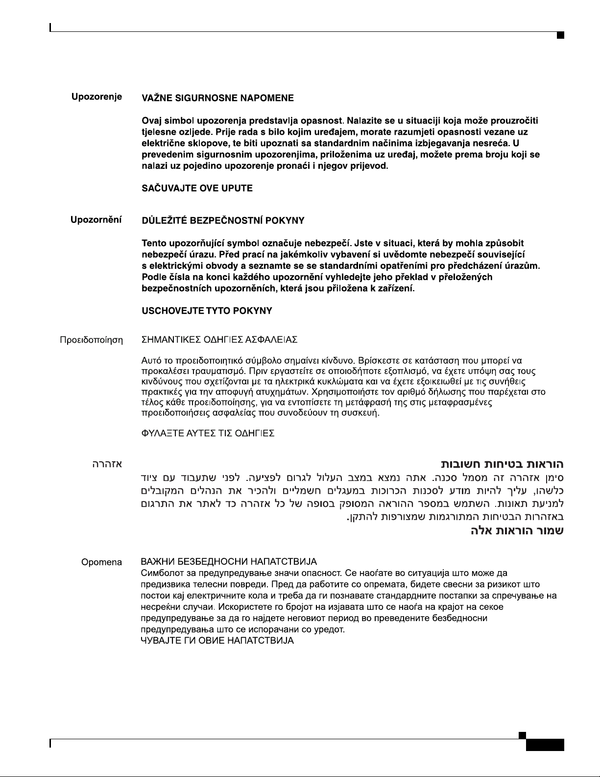
Figure 1-1 Catalyst 4948E and Catalyst 4948E-F Switches—Front View of Chassis
(Catalyst 4948E Switch Shown)
1 48 downlink ports 4 Status LEDs
2 4 uplink ports 5 Console port
3 Management port
Note The orientation of the Cisco logo shown in Figure 1-1 identifies the chassis as a Catalyst 4948E switch.
The Cisco logo that appears on the Catalyst
labels are placed on the Catalyst
4948E-F top cover to denote the direction of the airflow through the
4948E-F chassis top cover is rotated 180 degrees. Additional
chassis.
1-2
Catalyst 4948E and Catalyst 4948E-F Switch Installation Guide
OL-21561-02
Page 19
Chapter 1 Product Overview
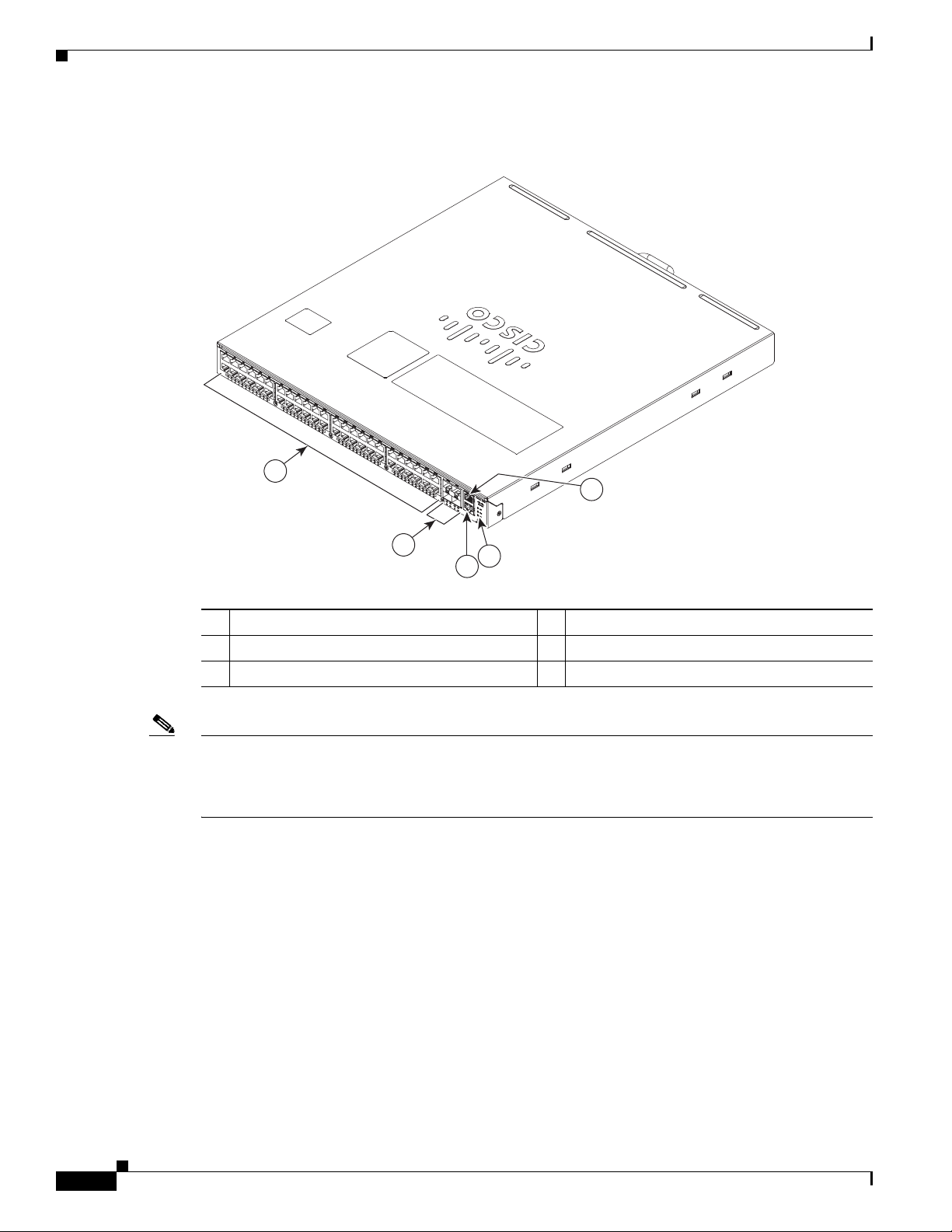
Figure 1-2 Catalyst 4948E and Catalyst 4948E-F Switches—Rear View of Chassis
1 Power supply 1 (primary) 3 Power supply 2 (redundant)
2 Fan tray
Features
PWR - 540 AC
100 - 240 VAC
7 - 3A
50 - 60 Hz
INPUT
OUTPUT
OK
OK
INPUT
PWR - 540 AC
100 - 240 VAC
OK
50 - 60 Hz
7 - 3A
OUTPUT
OK
330680
1
2
3
Features
This chapter describes the Catalyst 4948E and Catalyst 4948E-F switches and includes these sections:
• Features, page 1-3
• Physical and Environmental Specifications, page 1-7
• Fan Tray, page 1-8
• Front Panel LEDs, page 1-11
Table 1-1 lists the features of the Catalyst 4948E and the Catalyst 4948E-F switch chassis.
OL-21561-02
Catalyst 4948E and Catalyst 4948E-F Switch Installation Guide
1-3
Page 20

Features
Ta b l e 1-1 Catalyst 4948E and Catalyst 4948E-F Switch Features
Feature Description
Chassis
(both chassis)
Uplink ports
(both chassis)
1-RU, 48 10/100/1000 ports plus 4 1-GB/10-GB ports, fixed configuration
switch with redundant power supplies
The chassis has 4 1-GB or 10-GB uplink ports. An SFP or SFP+ transceiver
must be installed in the chassis port socket for the port to operate. Cable type
and recommended cabling distance for each port is determined by the type
of SFP or SFP+ transceiver installed in the uplink port. A bicolor port link
status LED is associated with each uplink port. LED colors indicate the
following status:
• Green—The link is established and operational.
• Amber—The port is disabled.
• Blinking amber—The system has detected a fault with the link.
• Off—No link is established or the transceiver is not installed in the port
socket.
Chapter 1 Product Overview
Downlink ports
(both chassis)
Console port
(both chassis)
Ethernet management port
(both chassis)
See Appendix B, “Transceiver, Chassis Connectors, and Cable and Adapter
Specifications” for supported SFP and SFP+ transceiver descriptions,
specifications, and cabling distances.
• The chassis has 48 10/100/1000BASE autonegotiating-capable
downlink ports. Each port has an RJ-45 connector. A bicolor port link
status LED is associated with each port. LED colors indicate the
following status:
• Green—The link is established and operational.
• Amber—The port is disabled.
• Blinking amber—The system has detected a fault with the link.
• Off—No link is established or no network interface cable is installed.
A console serial port (RJ-45) is provided for switch management using
standard console equipment. Additional information including a connector
pinout table is provided in
Appendix B, “Transceiver, Chassis Connectors,
and Cable and Adapter Specifications”for the console port.
Note A console cable is not provided in the accessory kit. It can be ordered
as an option.
• The Catalyst 4948E switch provides a 10/100/1000 RJ-45 port Ethernet
Management port that can be used to manage the switch through an
Ethernet network. This port can also be used to download software to the
switch or transfer files to remote servers for analysis or backup storage.
• The typical connection to the Management Ethernet port uses an
Ethernet cable with RJ-45 connectors at each end. The other end of the
cable typically connects to an Ethernet switch, hub, or router that
provides connectivity between the multishelf system and networks from
which system management is desired.
Appendix B, “Transceiver,
Chassis Connectors, and Cable and Adapter Specifications” contains
additional information for the Ethernet management port including a
connector pinout table.
1-4
Catalyst 4948E and Catalyst 4948E-F Switch Installation Guide
OL-21561-02
Page 21

Chapter 1 Product Overview
Table 1-1 Catalyst 4948E and Catalyst 4948E-F Switch Features (continued)
Feature Description
RESET switch
(both chassis)
• Resets and restarts the switch.
• The switch is recessed on chassis front panel and requires a pointed
object to access it.
Fan tray
Catalyst 4948E chassis
• The Catalyst 4948E chassis supports one hot-swappable fan tray (part
number WS-X4993=).
Note The fan trays are not interchangeable between the Catalyst 4948E
and the Catalyst
• The fan tray has four variable-speed 12 VDC fans.
• The fan tray installs in the rear of the chassis between the two power
4948E-F chassis.
supplies.
• The fan tray for the Catalyst 4948E (WS-X4993=) is color-coded dark
grey.
• A redundant pair of thermal sensors are positioned near the air inlet
(front of the chassis) to monitor the ambient air temperature and control
the fan tray fan speed.
• The airflow in the Catalyst 4948E chassis is from front to back.
• The chassis has a FAN LED (located on the chassis front panel) that
provides fan tray status.
Features
–
Red—One or more individual fans in the fan tray have failed.
–
Green—All fans in the fan tray are operating normally.
Catalyst 4948E-F chassis • The Catalyst 4948E-F chassis supports one hot-swappable fan tray (part
number WS-X4993-F=).
Note The fan trays are not interchangeable between the Catalyst 4948E
and the Catalyst
• The fan tray has four variable-speed 12 VDC fans.
• The fan tray installs in the rear of the chassis between the two power
4948E-F chassis.
supplies.
• The fan tray for the Catalyst 4948E-F is color-coded blue.
• A redundant pair of thermal sensors are positioned near the air inlet (rear
of the chassis) to monitor the ambient air temperature and control the fan
tray fan speed.
• The airflow in the Catalyst 4948E-F chassis is from back to front.
• The chassis has a FAN LED (located on the chassis front panel) that
provides fan tray status.
–
Red—One or more individual fans in the fan tray have failed.
–
Green—All fans in the fan tray are operating normally.
OL-21561-02
Catalyst 4948E and Catalyst 4948E-F Switch Installation Guide
1-5
Page 22

Features
Table 1-1 Catalyst 4948E and Catalyst 4948E-F Switch Features (continued)
Feature Description
Power supplies
Catalyst 4948E
• Supports one or two power supplies. The following power supplies are
supported:
–
PWR-C49E-300AC-R (300 W AC-input power supply).
–
PWR-C49-300DC (300 W DC-input power supply).
Note The power supplies are not interchangeable between the
Catalyst
• The front panels on both of the power supplies for the Catalyst 4948E
4948E and the Catalyst 4948E-F switch chassis.
are color-coded dark grey.
Note The 300 W AC-input power supply requires single-phase source AC.
Source AC can be out of phase between multiple power supplies
because all AC power supply inputs are isolated.
Note Appendix A, “Power Supply Specifications” contains additional
information on both of the power supplies.
Chapter 1 Product Overview
Note If the redundant power supply is not installed, the empty power
supply bay should be covered using the blank power supply cover
(p/n WS-X4994). The blank power supply cover is color-coded dark
grey.
Catalyst 4948E-F • Supports one or two power supplies. The following power supplies are
supported:
–
PWR-C49E-300AC-F (300 W AC-input power supply, reversed air
flow).
• The front panel on the power supply for the Catalyst 4948E-F is
color-coded blue.
Note The 300 W AC-input power supply requires single-phase source AC.
Source AC can be out of phase between multiple power supplies
because all AC power supply inputs are isolated.
Note Appendix A, “Power Supply Specifications” contains additional
information on both of the power supplies.
Note If the redundant power supply is not installed, the empty power
supply bay should be covered using the blank power supply cover
(p/n WS-X4994-F). The blank power supply cover is color-coded
blue.
1-6
Catalyst 4948E and Catalyst 4948E-F Switch Installation Guide
OL-21561-02
Page 23

Chapter 1 Product Overview
Physical and Environmental Specifications
Physical and Environmental Specifications
Table 1-2 and Ta ble 1-3 lists the Catalyst 4948E and Catalyst 4948E-F switch chassis environmental and
physical specifications.
Ta b l e 1-2 Catalyst 4948E and Catalyst 4948E-F Switch Specifications - Environment, Heat Dissipation, Shock and
Vibrations, Physical Characteristics, and Airflow
Item Specification
Environmental
Temperature, operating Certified for operation: 32° to 104°F (0° to 40°C)
Designed and tested for operation: 32° to 131°F (0° to 55°C)
Temperature, nonoperating
and storage
Thermal transition 0.5°C per minute (hot to cold)
Humidity (RH), ambient
(noncondensing) operating
Altitude, operating Certified for operation: 0 to 6500 ft (0 to 2000 m)
Heat Dissipation 1364 BTU/hour (worst case)
Shock and Vibration Refer to Appendix D, “Regulatory Compliance and Safety Information” for
Physical Characteristics
Dimensions (H x W x D) • 1.75 x 17.5 x 19.4 in. (4.4 x 44.4 x 49.3 cm).
Chassis unpackaged: –4° to 149°F (–20° to 65°C)
Chassis in protective shipping package: –40° to 158°F (–40° to 70°C)
0.33°C per minute (cold to hot)
Operating: 5% to 90%
Nonoperating and storage: 5% to 95%
Designed and tested for operation: –200 to 10,000 ft (–60 to 3000 m)
shock and vibration compliance information for the switch.
• Chassis requires 1 RU.
• The Catalyst 4948E and the Catalyst 4948E-F switch chassis are
designed to install in standard 19-inch equipment racks that meet
ANSI/EIA
310-D, IEC 60297, and ETS 300-119 standards.
Weight • 14 lb (6.35 kg). Base system; no power supplies and no fan tray.
• 19 lb (8.62 kg). Fully loaded system; two power supplies and a fan tray.
Airflow • 28 CFM (low speed)
• 44 CFM (high speed)
Ta b l e 1-3 Catalyst 4948E and Catalyst 4948E-F Switch Specifications - Acoustic Noise
Acoustic Noise
Measured per ISO 7779 and declared per ISO 9296
Bystander positions operating mode at 25°C ambient.
Sound Pressure, dBA Sound Power, dBA
Model Typical, LpAm Maximum, LpAD Typical, LwA Maximum, LwAD
WS-C4948E 55.6 58.6 62.6 65.6
Catalyst 4948E and Catalyst 4948E-F Switch Installation Guide
OL-21561-02
1-7
Page 24

Fan Tray
Fan Tray
Note The two fan trays are not interchangeable between the Catalyst 4948E and the Catalyst 4948E-F chassis.
Chapter 1 Product Overview
Both the Catalyst 4948E and the Catalyst 4948E-F switch chassis have a fan tray that is mounted in the
rear of the chassis between the two power supplies. The Catalyst 4948E chassis fan tray (WS-X4993=)
provides front-to-back air flow in the chassis and has a front panel that is color-coded dark grey. The
Catalyst
4948E-F chassis fan tray (WS-X4993-F=) provides back-to-front air flow and has a front panel
that is color-coded blue.
The WS-X4993-F fan tray is keyed to prevent insertion in the Catalyst 4948E chassis.
Individual fan speed within the fan trays is controlled by redundant temperature sensors located at the
air flow inlet (in the front of the chassis for the Catalyst
Catalyst
4948E-F). There are six programmable temperature thresholds that trigger fan speed change. If
4948E and in the rear of the chassis for the
there is an individual fan failure, the fan speed on the remaining fans is adjusted to try to compensate for
the loss of the fan.
Table 1-4 lists the fan speed settings and the associated temperature thresholds.
Ta b l e 1-4 Fan Speeds Versus Chassis Temperature Thresholds
Fan Speed
Setting
PWM1 Duty
Cycle
Chassis Temperature Range Thresholds
Speed 0 41% T2—89.6°F (32°C)
Note At T2, the fan speed increases to Speed 1.
Speed 1 56% • T1—82.4°F (28°C)
• T4—102.2°F (39°C)
Note At T1, the fan speed decreases to Speed 0. At T4, the fan
Speed 2 75% T3—95.0°F (35°C)
T6—116.6°F (47°C)
Note At T3, the fan speed decreases to Speed 1. At T6, the fan
Speed 3
1. Pulse-Width Modulation
2. Speed 3 is a fixed value and cannot be altered.
2
100% T5—Greater than 109.4°F (43°C)
Catalyst 4948E Fan Tray (WS-X4993=)
speed increases to Speed
speed increases to Speed
2.
3.
1-8
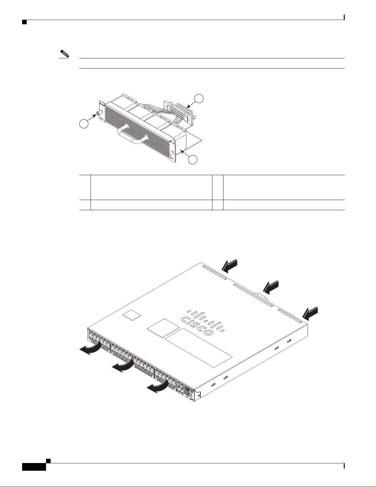
The Catalyst 4948E fan tray (WS-X4993) contains four variable-speed, 12 VDC fans. (See Figure 1-3.)
The fan tray is mounted in the rear of the chassis between the two power supplies.
Note The WS-X4993 fan tray is not interchangeable with the WS-X4993-F fan tray.
Catalyst 4948E and Catalyst 4948E-F Switch Installation Guide
OL-21561-02
Page 25
Chapter 1 Product Overview
207440
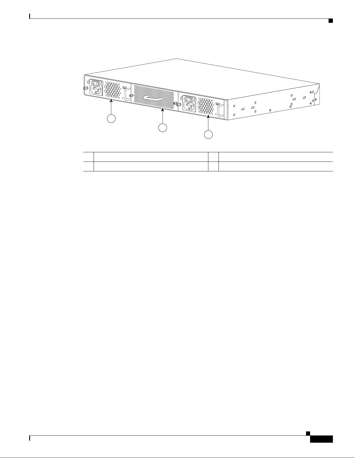
Figure 1-3 Catalyst 4948E Fan Tray
2
1 Backplane connector 3 12 VDC fan (4X). Air is drawn in from the
2 Captive installation screw (2X)
The fan tray draws in air through vents at the front of the chassis and exhausts it through the rear of the
chassis as shown in
Fan Tray
1
278085
3
front of the chassis and exhausted through the
rear of the chassis.
Figure 1-4.
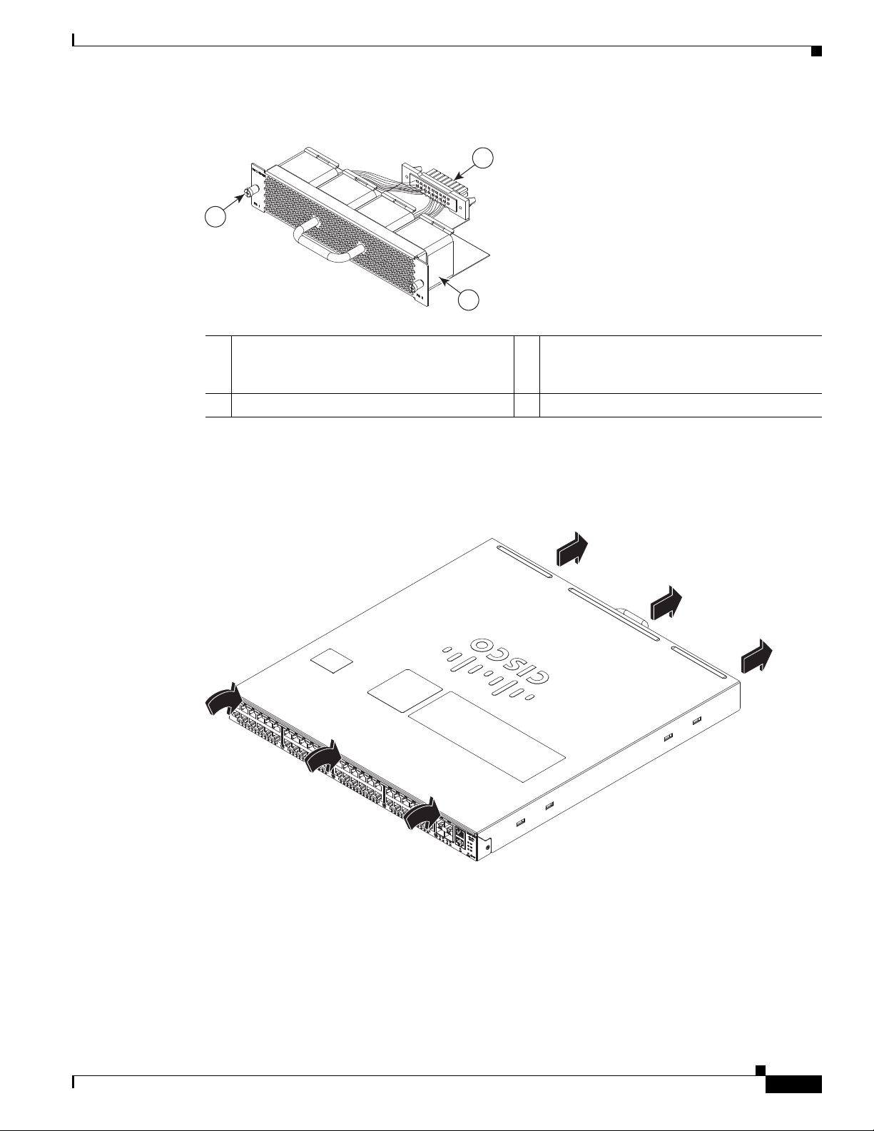
Figure 1-4 Catalyst 4948E Chassis Airflow
Catalyst 4948E-F Fan Tray (WS-X4993-F=)
The Catalyst 4948E-F chassis fan tray (WS-X4993-F=) contains four variable-speed, 12 VDC fans. (See
Figure 1-5.) The fan tray is mounted in the rear of the chassis between the two power supplies.
OL-21561-02
Catalyst 4948E and Catalyst 4948E-F Switch Installation Guide
1-9
Page 26
Fan Tray
Chapter 1 Product Overview
Note The WS-X4993-F fan tray is keyed to prevent insertion into the Catalyst 4948E switch chassis.
Figure 1-5 Catalyst 4948E-F Fan Tray
1
2
278085
3
1 Backplane connector 3 12 VDC fan (4X). Air is drawn in from the
rear of the chassis and exhausted through the
front of the chassis.
2 Captive installation screw (2X)
The fan tray draws in air through vents at the rear of the chassis and exhausts it through the front of the
chassis as shown in
Figure 1-6 Catalyst 4948E-F Chassis Airflow
Figure 1-6.
281614
1-10
Catalyst 4948E and Catalyst 4948E-F Switch Installation Guide
OL-21561-02
Page 27
Chapter 1 Product Overview
278086
1
2
4
5
3
6
Front Panel LEDs
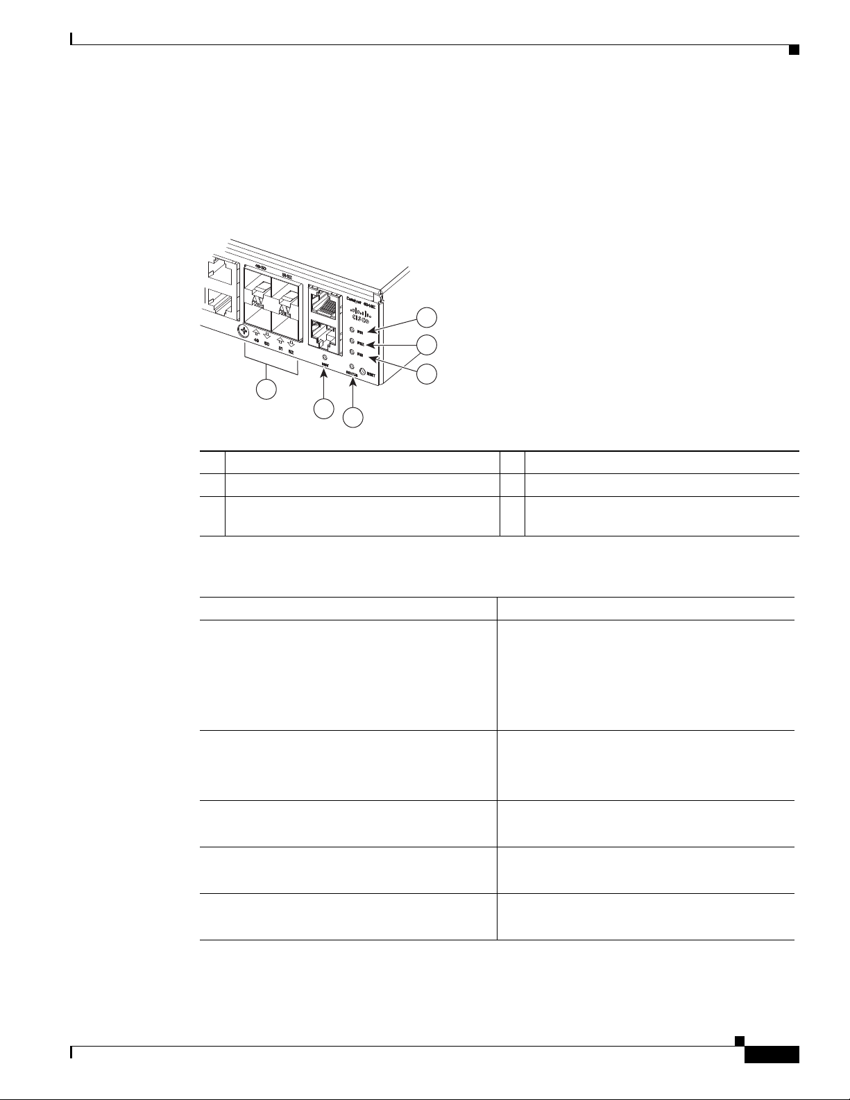
A set of LEDs on the chassis front panel provide visual status for the switch. (See Figure 1-7.) Tab le 1-5
lists the Catalyst 4948E and Catalyst 4948E-F switch chassis front panel LEDs and their meanings.
Figure 1-7 Front Panel LEDs
Front Panel LEDs
1 PS1 (power supply 1) 4 STATUS
2 PS2 (power supply 2) 5 MGT (management port LED)
3 FAN (fa n tray) 6 LINK (port status). One LED for each uplink
and downlink port.
Ta b l e 1-5 Front Panel LED Descriptions
LED State and Meaning
STATUS Green—The system is up and running.
Red—System fault.
Flashing amber—Power-on self-test (POST) boot
up.
Off—System is not powered up.
LINK
48 10/100/1000 downlink port LEDs and 4
SFP/SFP+ uplink port LEDs
FAN
(Fan tray)
PS1
(Power supply 1)
PS2
(Power supply 2)
1. There are three additional LEDs mounted on the power supply front panel that provide power supply status. These LEDs are
only visible from the back of the chassis. For a description of the LEDs, see the
(PWR-C49E-300AC-R)” section on page A-1.
1
1
Green—Link is established.
Amber—Administrative disabled.
Off—No link is detected.
Green—Fan tray OK.
Red—One or more fan failures.
Green—AC-input or DC-input power is OK.
Red—Power supply fault detected.
Green—AC-input or DC-input power is OK.
Red—Power supply fault detected.
“300 W AC-Input Power Supply
OL-21561-02
Catalyst 4948E and Catalyst 4948E-F Switch Installation Guide
1-11
Page 28

Front Panel LEDs
Chapter 1 Product Overview
1-12
Catalyst 4948E and Catalyst 4948E-F Switch Installation Guide
OL-21561-02
Page 29

CHAP T ER
2
Preparing for Installation
Revised: July 2012
Planning a proper location for the switch and the layout of your equipment rack or wiring closet is
essential for successful system operation. Equipment placed too close together or inadequately
ventilated can cause system overtemperature conditions. In addition, poor equipment placement can
make network interface connections inaccessible and difficult to maintain.
This chapter describes how to prepare your site for switch installation and includes these sections:
• Safety, page 2-1
• Site Requirements, page 2-2
• System Grounding, page 2-7
• Power Requirements, page 2-11
• Cabling Requirements, page 2-13
Safety
• Site Preparation Checklist, page 2-13
Tip For additional information about the Cisco Catalyst 4948E or the Catalyst 4948E-F switch (including
configuration examples and troubleshooting information), see the documents listed on this page:
http://www.cisco.com/en/US/products/ps6021/tsd_products_support_series_home.html
Safety warnings appear throughout this publication in procedures that may harm you if performed
incorrectly. A warning symbol precedes each warning statement. The warnings below are general
warnings that are applicable to the entire publication.
Warning
Only trained and qualified personnel should be allowed to install, replace, or service this equipment.
Statement 1030
OL-21561-02
Catalyst 4948E and Catalyst 4948E-F Switch Installation Guide
2-1
Page 30

Site Requirements
Chapter 2 Preparing for Installation
Warning
Warning
This unit is intended for installation in restricted access areas. A restricted access area can be
accessed only through the use of a special tool, lock and key, or other means of security.
Statement 1017
Voltages that present a shock hazard may exist on Power over Ethernet (PoE) circuits if
interconnections are made using uninsulated exposed metal contacts, conductors, or terminals.
Avoid using such interconnection methods, unless the exposed metal parts are located within a
restricted access location and users and service people who are authorized within the restricted
access location are made aware of the hazard. A restricted access area can be accessed only
through the use of a special tool, lock and key or other means of security.
Site Requirements
These following sections describe some of the basic site requirements that you should be aware of as you
prepare to install your Catalyst
• Rack-Mounting Guidelines, page 2-2
• Temperature, page 2-3
• Air Flow, page 2-4
• Humidity, page 2-5
• Altitude, page 2-5
Statement 1072
4948E or Catalyst 4948E-F switch:
• Dust and Particulates, page 2-5
• Corrosion, page 2-6
• Electromagnetic and Radio Frequency Interference, page 2-6
• Shock and Vibration, page 2-7
• Maintaining Safety with Electricity, page 2-9
• Preventing Electrostatic Discharge Damage, page 2-10
Rack-Mounting Guidelines
A rack-mount kit (69-2037-xx) is included in the accessory kit for mounting the switch in a standard
19-inch (48.3
• Racks with obstructions (such as power strips) that could impair access to the switch
Before rack-mounting the switch, ensure the following:
• The equipment rack is the proper size.
–
–
–
cm) equipment rack. This rack-mount kit is not suitable for use in the following situations:
The width of the rack, between the two front-mounting strips or rails, must be 17.75 inches
(45.09
cm).
The depth of the rack, between the front- and rear-mounting strips, must be at least 19.25 inches
(48.9
cm) but not more than 32.5 inches (82.5 cm).
The rack must have sufficient vertical clearance to insert the chassis. The chassis height is 1 U
(1.75
inches (4.45 cm)).
2-2
Catalyst 4948E and Catalyst 4948E-F Switch Installation Guide
OL-21561-02
Page 31

Chapter 2 Preparing for Installation
• The equipment rack is stable and in no danger of falling over.
–
–
–
–
–
• The equipment rack is properly ventilated.
–
–
–
–
Site Requirements
Ensure that the shelf is constructed to support the weight and dimensions of the chassis.
We recommend that you bolt the rack to the floor.
Mount the unit at the bottom of the rack if it is the only unit in the rack.
Install heavier equipment in the lower half of the rack to maintain a low center of gravity and
prevent the rack from becoming top-heavy and tipping over.
Install the stabilizers before mounting or servicing the switch in the rack (if the rack is provided
with stabilizing devices).
Install the chassis in an enclosed rack only if it has adequate ventilation or an exhaust fan; use
an open rack whenever possible.
Ensure that the ambient temperature of the rack environment does not exceed a maximum
temperature of 104°F (40°C). If the switch is installed in a closed or multiunit rack assembly,
the ambient operating temperature of the rack environment might be higher than the ambient
room temperature.
Ensure that the ventilation system in a closed rack does not prevent cooling by creating negative
pressure around the chassis and redirecting the air away from the chassis intake vent. If
necessary, operate the chassis with the rack open.
Ensure that equipment installed near the bottom of a rack does not generate excessive heat,
which can be drawn upward and into the air intakes of equipment above. This situation can
cause overtemperature conditions in the chassis at or near the top of the rack.
Temperature
–
Consider the equipment and cabling that is already installed in the rack. Ensure that cables from
other equipment will not obstruct the airflow through the chassis or impair access to the power
supplies or switching modules. Route cables away from field-replaceable components to avoid
disconnecting cables unnecessarily for equipment maintenance or upgrades.
–
Allow at least 3 to 4 feet (91.4 to 121.9 cm) of clearance behind the rack for maintenance and
removal of switch assemblies. If the rack is mobile, you can push it back within 1 foot (30.45
cm) of a wall or cabinet for normal operation and pull it out when necessary for maintenance.
Temperature extremes can cause a system to operate at reduced efficiency and cause a variety of
problems, including premature aging and failure of chips, and failure of mechanical devices. Extreme
temperature fluctuations can cause chips to become loose in their sockets. Observe the following
guidelines:
• Ensure that the system is operating in an environment no colder than 50°F (10°C) or hotter than
104°F (40°C).
• Ensure that the chassis has adequate ventilation.
• Use proper air circulation management techniques. Chassis mounted higher in a rack enclosure are
susceptable to higher ambient air temperatures due to the heat generated from chassis that are
mounted below the chassis in the rack.
• Do not place the chassis within a closed-in wall unit or on top of cloth, which can act as insulation.
• Do not place the chassis where it will receive direct sunlight, particularly in the afternoon.
• Do not place the chassis next to a heat source of any kind, including heating vents.
OL-21561-02
Catalyst 4948E and Catalyst 4948E-F Switch Installation Guide
2-3
Page 32

Site Requirements
Air Flow
Chapter 2 Preparing for Installation
• Ensure that all slots and openings on a chassis remain unobstructed, especially the fan tray vent at
the back of the chassis. Adequate ventilation is particularly important at high altitudes where the air
is thinner.
• Clean the installation site at regular intervals to avoid buildup of dust and debris, which can cause a
system to overheat.
• Allow a 2-hour warm-up period to bring the chassis up to normal operating temperature before
turning it on for chassis that have been exposed to abnormally cold temperatures.
Failure to observe these guidelines can damage internal chassis components.
Note The Catalyst 4948E and the Catalyst 4948E-F switches are equipped with internal air temperature
sensors that are triggered above 104°F (40°C) generating a minor alarm and above 131°F (55°C) generating
a major alarm. Enter the command show environment status to determine the exact temperature when the
alarms are generated.
The Catalyst 4948E and Catalyst 4948E-F switches are designed to be installed in an environment where
there is a sufficient volume of air available to cool the chassis and the power supplies. Any constraints
placed on the free flow of air through the chassis or an elevated ambient air temperature can cause the
switch to overheat and shut down.
To maintain proper air circulation through the switch chassis, we recommend that you maintain a
minimum 6-inch (15
cm) separation between a wall and the chassis hot air exhaust. Failure to maintain
adequate spacing between chassis can cause the switch chassis that is drawing in the hot exhaust air to
overheat and fail.
If you are installing your Catalyst 4948E or Catalyst 4948E-F switch chassis in an enclosed or partially
enclosed rack, we strongly recommend that you verify that your site meets the following guidelines:
• Verify that the ambient air temperature within the enclosed or partially enclosed rack is within the
chassis operating temperature limits. After installing the chassis in the rack, power up the chassis
and allow the chassis temperature to stabilize (approximately 2 hours). Measure the ambient air
temperature at the chassis air intake grill and at the chassis air exhaust grill by positioning an
external temperature probe approximately 1
–
If the ambient intake air temperature is less than 104°F (40°C), the rack meets the intake air
inch (2.5 cm) away from the grills.
temperature criterion.
–
If the ambient intake air temperature exceeds 104°F (40°C), the system might experience minor
temperature alarms and is in danger of overheating.
–
If the ambient intake air temperature equals or is greater than 131°F (55°C), the system will
experience a major temperature alarm and shut down.
• Verify that the enclosed or partially enclosed rack allows an adequate flow of air through the switch
chassis as follows:
–
If the difference between the measured intake air temperature and the exhaust air temperature
does not exceed 10°C, there is sufficient airflow in the rack.
–
If the difference in air temperature exceeds 10°C, there is insufficient airflow to cool the chassis.
2-4
Catalyst 4948E and Catalyst 4948E-F Switch Installation Guide
OL-21561-02
Page 33

Chapter 2 Preparing for Installation
Note The 10°C temperature differential between the intake and the exhaust must be determined by
• Plan for future growth. Your Catalyst 4948E or Catalyst 4948E-F switches currently installed in an
• If you are installing the Catalyst 4948E-F in a data center that uses the hot isle and cold isle style of
Humidity
Site Requirements
taking measurements using external digital temperature probes. Do not use the chassis internal
temperature sensors to measure the temperature differential.
enclosed or partially enclosed rack might meet ambient air temperature and air flow requirements
now. However, if you add more chassis or other equipment to the rack, the additional heat generated
might cause the ambient air temperature within the rack to exceed 104°F (40°C) and can cause minor
alarms.
cooling, we recommend that you use an optional inlet air duct to extend the chassis air intake to the
cold isle. Panduit Corporation manufactures a Modular ToR Switch Inlet Duct (Model CDE2) that
can be installed along with the Catalyst
the cold isle at the front of the rack enclosure.
4948E-F chassis to extend the switch chassis air intake to
High-humidity conditions can cause moisture migration and penetration into the system. This moisture
can cause corrosion of internal components and degradation of properties such as electrical resistance,
thermal conductivity, physical strength, and size. Extreme moisture buildup inside the system can result
in electrical shorts, which can cause serious damage to the system. Each system is rated to operate at 8
to 80 percent relative humidity, with a humidity gradation of 10 percent per hour. In storage, a system
can withstand from 5 to 95 percent relative humidity. Buildings in which climate is controlled by
air-conditioning in the warmer months and by heat during the colder months usually maintain an
acceptable level of humidity for system equipment. However, if a system is located in an unusually
humid location, a dehumidifier can be used to maintain the humidity within an acceptable range.
Altitude
Operating a system at high altitude (low pressure) reduces the efficiency of forced and convection
cooling and can result in electrical problems related to arcing and corona effects. This condition can also
cause sealed components with internal pressure, such as electrolytic capacitors, to fail or perform at
reduced efficiency. Each system is rated to operate at altitudes from –50 to 6500
1981
meters) and can be stored at altitudes of –50 to 35,000 feet (–16 to 10,668 meters).
Dust and Particulates
Fans cool the power supplies and the system components by drawing in room temperature air, circulating
the air through the power supplies and the chassis, and exhausting the heated air out through various
openings in the chassis. However, fans also ingest dust and other particulates, causing contaminant
buildup on the fan blades and in the system. This can create a thermal blanket on components increasing
the internal chassis temperature.
A clean operating environment can greatly reduce the negative effects of dust and other particulates. The
standards listed below provide guidelines for acceptable working environments and acceptable levels of
suspended particulate matter:
feet (–16 to
OL-21561-02
• Network Equipment Building Systems (NEBS) GR-63-CORE
Catalyst 4948E and Catalyst 4948E-F Switch Installation Guide
2-5
Page 34

Site Requirements
• National Electrical Manufacturers Association (NEMA) Type 1
• International Electrotechnical Commission (IEC) IP-20
Corrosion
Corrosion of system connectors is a gradual process that can eventually lead to intermittent failures of
electrical circuits. The oil from a person’s fingers or prolonged exposure to high temperature or humidity
can corrode the gold-plated edge connectors and pin connectors on various components in the system.
To prevent corrosion, avoid touching contacts on boards and cards, and protect the system from extreme
temperatures and moist, salty environments.
Electromagnetic and Radio Frequency Interference
Electromagnetic interference (EMI) and radio frequency interference (RFI) from a system can adversely
affect devices such as radio and television (TV) receivers operating near the system. Radio frequencies
emanating from a system can also interfere with cordless and low-power telephones. Conversely, RFI
from high-power telephones can cause spurious characters to appear on the system monitor. RFI is
defined as any EMI with a frequency above 10 kilohertz (kHz). This type of interference can travel from
the system to other devices through the power cable and power source or through the air like transmitted
radio waves. The Federal Communications Commission (FCC) publishes specific regulations to limit the
amount of EMI and RFI emitted by computing equipment. Each system meets these FCC regulations. To
reduce the possibility of EMI and RFI, follow these guidelines:
Chapter 2 Preparing for Installation
• Only operate the system with the chassis covers installed.
• Ensure that an unused power supply bay has a metal cover plate installed.
• Ensure that the screws on all peripheral cable connectors are securely fastened to their
corresponding connectors on the back of the chassis.
• Always use shielded cables with metal connector shells for attaching peripherals to the system.
When wires are run for any significant distance in an electromagnetic field, interference can occur
between the field and the signals on the wires. This fact has two implications for the construction of plant
wiring:
• Bad wiring practice can result in radio interference emanating from the plant wiring.
• Strong EMI, especially when it is caused by lightning or radio transmitters, can destroy the signal
drivers and receivers in the chassis, and even create an electrical hazard by conducting power surges
through lines into equipment.
Note To predict and remedy strong EMI, you may also need to consult experts in radio frequency interference
(RFI).
If you use twisted-pair cable in your plant wiring with a good distribution of grounding conductors, the
plant wiring is unlikely to emit radio interference. If you exceed the recommended distances, use a
high-quality twisted-pair cable with one ground conductor for each data signal when applicable.
2-6
Caution Category 5e, Category 6, and Category 6a cables can store large levels of static electricity because of the
dielectric properties of the materials used in their construction. Always ground the cables (especially in
new cable runs) to a suitable and safe earth ground before connecting them to the module.
Catalyst 4948E and Catalyst 4948E-F Switch Installation Guide
OL-21561-02
Page 35

Chapter 2 Preparing for Installation
If the wires exceed the recommended distances, or if wires pass between buildings, give special
consideration to the effect of a lightning strike in your vicinity. The electromagnetic pulse caused by
lightning or other high-energy phenomena can easily couple enough energy into unshielded conductors
to destroy electronic devices. If you previously have had similar problems, you might want to consult
experts in electrical surge suppression and shielding.
Shock and Vibration
Catalyst 4948E and Catalyst 4948E-F switches have been shock- and vibration-tested for operating
ranges, handling, and earthquake standards to NEBS (Zone 4 per GR-63-Core). These tests have been
conducted in earthquake environment and criteria, office vibration and criteria, transportation vibration
and criteria, and packaged equipment shock.
Power Source Interruptions
Systems are especially sensitive to variations in voltage supplied by the AC power source. Overvoltage,
undervoltage, and transients (or spikes) can erase data from memory or even cause components to fail.
To protect against these types of problems, power cables should always be properly grounded. Also,
place the system on a dedicated power circuit (rather than sharing a circuit with other heavy electrical
equipment). In general, do not allow the system to share a circuit with any of the following:
Power Source Interruptions
• Copy machines
• Air conditioners
• Vacuum cleaners
• Space heaters
• Power tools
• Teletype machines
• Laser printers
• Facsimile machines
• Any other motorized equipment
Besides these appliances, the greatest threats to a system power supply are surges or blackouts that are
caused by electrical storms. Whenever possible, turn off the system and any peripherals, and unplug
them from their power sources during thunderstorms. If a blackout occurs—even a temporary
one—while the system is turned on, turn off the system immediately and disconnect it from the electrical
outlet. Leaving the system on may cause problems when the power is restored; all other appliances left
on in the area can create large voltage spikes that can damage the system.
System Grounding
You must install a NEBS-compliant system ground as part of the chassis installation process. Chassis
installations that rely only on the AC third-prong ground are insufficient to properly and adequately
ground the systems. Both chassis comes with a ground lug and two M4 bolts as part of the accessory kit.
The lug attaches to the chassis grounding pad with the two bolts. A 6
must be used to connect the ground lug to the NEBS-compliant building ground.
AWG copper wire (not provided)
OL-21561-02
Catalyst 4948E and Catalyst 4948E-F Switch Installation Guide
2-7
Page 36

System Grounding
Caution Installations that rely solely on system grounding using only an AC third-prong ground run a
Chapter 2 Preparing for Installation
Proper grounding practices ensure that the buildings and the installed equipment within them have
low-impedance connections and low-voltage differentials between chassis. When you include
NEBS-compliant system grounds, you reduce or prevent shock hazards, greatly reduce the chances of
equipment damage due to transients, and substantially reduce the potential for data corruption.
Without proper and complete system grounding, you run the risk of increased component damage due to
ESD. Additionally, you have a greatly increased chance of data corruption, system lockup and frequent
system reboot situations by not using a system (NEBS compliant) ground.
substantially greater risk of equipment problems and data corruption than those installations that use
both the AC third-prong ground and a properly installed system (NEBS compliant) ground.
Table 2-1 lists some general grounding practice guidelines.
Ta b l e 2-1 Grounding Practice Guidelines
Environment Electromagnetic
Noise Severity Level
Commercial building is
High All lightning protection devices must be
subjected to direct lightning
strikes.
For example, some places in the
United States, such as Florida,
are subject to more lightning
strikes than other areas.
Commercial building is located
High Grounding best practices must be closely
in an area where lightning storms
frequently occur but is not
subject to direct lightning
strikes.
Commercial building contains a
Medium to High Grounding best practices must be closely
mix of information technology
equipment and industrial
equipment, such as welding.
Existing commercial building is
Medium Grounding best practices must be closely
not subject to natural
environmental noise or
man-made industrial noise. This
building contains a standard
office environment. This
installation has a history of
malfunction due to
electromagnetic noise.
Grounding Recommendations
installed in strict accordance with
manufacturer recommendations. Conductors
carrying lightning current should be spaced
away from power and data lines in
accordance with applicable
recommendations and codes. Best grounding
practices must be closely followed.
followed.
followed.
followed. Determine source and cause of
noise if possible, and mitigate as closely as
possible at the noise source or reduce
coupling from the noise source to the victim
equipment.
2-8
Catalyst 4948E and Catalyst 4948E-F Switch Installation Guide
OL-21561-02
Page 37

Chapter 2 Preparing for Installation
Table 2-1 Grounding Practice Guidelines (continued)
System Grounding
Environment Electromagnetic
Grounding Recommendations
Noise Severity Level
New commercial building is not
subject to natural environmental
noise or man-made industrial
noise. This building contains a
standard office environment.
Low Grounding best practices should be followed
as closely as possible. Electromagnetic noise
problems are not anticipated, but installing a
best practice grounding system in a new
building is often the least expensive route
and the best way to plan for the future.
Existing commercial building is
not subject to natural
environmental noise or
man-made industrial noise. This
building contains a standard
Low Grounding best practices should be followed
as much as possible. Electromagnetic noise
problems are not anticipated, but installing a
best practice grounding system is always
recommended.
office environment.
Note In all situations, grounding practices must comply with Section 250 of the National Electric Code (NEC)
requirements or local laws and regulations. A 6
AWG grounding wire is preferred from the chassis to the
rack ground or directly to the common bonding network (CBN). The equipment rack should also be
connected to the CBN with 6 AWG grounding wire.
Caution Category 5e, Category 6, and Category 6a cables can store large levels of static electricity because of the
dielectric properties of the materials used in their construction. Always ground the cables (especially in
new cable runs) to a suitable and safe earth ground before connecting them to the port on the switch.
Maintaining Safety with Electricity
When working on electrical equipment, follow these guidelines:
• Do not work alone if potentially hazardous conditions exist anywhere in your work space.
• Never assume that power is disconnected from a circuit; always check the circuit before working on
it.
• Look carefully for possible hazards in your work area, such as damp floors, ungrounded power
extension cables, frayed or damaged power cords, and missing safety grounds.
• If an electrical accident occurs, proceed as follows:
–
Use extreme caution; do not become a victim yourself.
–
Disconnect power from the system.
–
If possible, send another person to get medical aid. Otherwise assess the condition of the victim,
and then call for help.
–
Determine if the person needs rescue breathing or external cardiac compressions; then take
appropriate action.
• Use the product within its marked electrical ratings and product usage instructions.
• Install the product in compliance with local and national electrical codes.
OL-21561-02
Catalyst 4948E and Catalyst 4948E-F Switch Installation Guide
2-9
Page 38

System Grounding
Chapter 2 Preparing for Installation
• If any of the following conditions occur, contact the Cisco Technical Assistance Center:
–
The power cable or plug is damaged.
–
An object has fallen into the product.
–
The product has been exposed to water or other liquids.
–
The product has been dropped or shows signs of damage.
–
The product does not operate correctly when you follow the operating instructions.
• Use the correct external power source. Operate the product only from the type of power source
indicated on the electrical ratings label. If you are not sure of the type of power source required,
consult the Cisco Technical Assistance Center or a local electrician.
• Use approved power cables only. You have been provided with one or more power cables with your
chassis power supply that are intended for use in your country, based on the shipping location.
Should you need to purchase additional power cables, ensure that they are rated for the product and
for the voltage and current marked on the product’s electrical ratings label. The voltage and current
rating of the power cable should be greater than the ratings marked on the label.
• To help prevent electrical shock, plug all power cables into properly grounded electrical outlets.
These power cables are equipped with three-prong plugs to help ensure proper grounding. Do not
use adapter plugs or remove the grounding prong from a power cable.
• Observe power strip ratings. Make sure that the total current rating of all products that are plugged
into the power strip does not exceed 80
• Do not modify power cables or plugs yourself. Consult with a licensed electrician or your power
percent of the power strip rating.
company for site modifications. Always follow your local and national wiring codes.
Preventing Electrostatic Discharge Damage
Electrostatic discharge (ESD) damage, which can occur when modules or other FRUs are improperly
handled, results in intermittent or complete failures. Modules consist of printed circuit boards that are
fixed in metal carriers. Electromagnetic interference (EMI) shielding and connectors are integral
components of the carrier. Although the metal carrier helps to protect the board from ESD, always use
an ESD grounding strap when handling modules.
To prevent ESD damage, follow these guidelines:
• Always use an ESD wrist strap and ensure that it makes maximum contact with bare skin. ESD
grounding straps are available with banana plugs, metal spring clips, or alligator clips. If you choose
to use the disposable ESD wrist strap supplied with most FRUs or an ESD wrist strap equipped with
an alligator clip, you must attach the system ground lug to the chassis in order to provide a proper
grounding point for the ESD wrist strap.
Note This system ground is also referred to as the network equipment building system (NEBS)
ground.
• If your chassis does not have the system ground attached, you must install the system ground.
2-10
Catalyst 4948E and Catalyst 4948E-F Switch Installation Guide
OL-21561-02
Page 39

Chapter 2 Preparing for Installation
After you install the system ground lug, follow these steps to correctly attach the ESD wrist strap:
Step 1 Attach the ESD wrist strap to bare skin as follows:
a. If you are using the ESD wrist strap supplied with the FRUs, open the wrist strap package and
unwrap the ESD wrist strap. Place the black conductive loop over your wrist and tighten the strap
so that it makes good contact with your bare skin.
b. If you are using an ESD wrist strap equipped with an alligator clip, open the package and remove
the ESD wrist strap. Locate the end of the wrist strap that attaches to your body and secure it to your
bare skin.
Step 2 Grasp the spring or alligator clip on the ESD wrist strap and momentarily touch the clip to a bare metal
spot (unpainted surface) on the rack. We recommend that you touch the clip to an unpainted rack rail so
that any built-up static charge is then safely dissipated to the entire rack.
Step 3 Attach either the spring clip or the alligator clip to the ground lug screw as follows:
a. If you are using the ESD wrist strap that is supplied with the FRUs, squeeze the spring clip jaws
open, position the spring clip to one side of the system ground lug screw head, and slide the spring
clip over the lug screw head so that the spring clip jaws close behind the lug screw head.
Power Requirements
Note The spring clip jaws do not open wide enough to fit directly over the head of the lug screw
or the lug barrel.
b. If you are using an ESD wrist strap that is equipped with an alligator clip, attach the alligator clip
directly over the head of the system ground lug screw or to the system ground lug barrel.
Caution For safety, periodically check the resistance value of the antistatic strap. The measurement should be
between 1 and 10 megohm (Mohm).
Power Requirements
When preparing your site for the switch installation, follow these general requirements:
• In systems configured with two power supplies, connect each of the two power supplies to a separate
input power source. If you fail to do this, your system might be susceptible to total power failure
due to a fault in the external wiring or a tripped circuit breaker.
• To prevent a loss of input power, be sure that the total maximum load on each source circuit is within
the current ratings of the wiring and breakers.
• In some systems, you may decide to use an uninterruptible power supply (UPS) to protect against
power failures at your site. Be aware when selecting a UPS that some UPS models that use
ferroresonant technology can become unstable when operating with the power supplies which use
power factor correction (PFC). This can cause the output voltage waveform to the switch to become
distorted resulting in an undervoltage situation in the system.
OL-21561-02
Catalyst 4948E and Catalyst 4948E-F Switch Installation Guide
2-11
Page 40

Power Requirements
Power Connection Guidelines for AC-Powered Systems
This section provides some basic guidelines for connecting the AC power supplies to the site power
source:
• Each chassis power supply should have a separate, dedicated branch circuit.
• For North America:
–
The 300 W power supply requires a 15 A circuit.
• For International:
–
Circuits should be sized according to local and national codes.
• If you are using a 200/240 VAC power source in North America, the circuit must be protected by a
two-pole circuit breaker.
• The source AC outlet must be within 6 feet (1.8 meters) of the system and should be easily
accessible.
• The AC power receptacles used to plug in the chassis must be the grounding type. The grounding
conductors that connect to the receptacles should connect to protective earth ground at the service
equipment.
Chapter 2 Preparing for Installation
Power Connection Guidelines for DC-Powered Systems
This section provides the basic guidelines for connecting the Catalyst 4948E switch DC-input power
supplies to the site power source:
• All power connection wiring should conform to the rules and regulations in the National Electrical
Code (NEC), as well as any local codes.
• The DC return must remain isolated from the system frame and the chassis (DC-I).
• For DC power cables, we recommend that you use commensurately rated, high-strand-count copper
wire cable. Connection to the DC-input power supply requires one earth ground cable, one source
DC (–), and one source DC return (+). The length of the cables depends on your switch location.
The cables and the lugs required to attach the source DC cables to the power supply are not available
from Cisco Systems. They are available from any commercial cable vendor.
• The color coding of the source DC power cable leads depends on the color coding of the site DC
power source. Typically, green or green and yellow indicate that the cable is a ground cable. Because
there is no color code standard for source DC wiring, you must ensure that the power cables are
connected to the DC-input power supply terminal block in the proper (+) and (–) polarity. In some
cases, the source DC cable leads might have a positive (+) or a negative (–) label. This label is a
relatively safe indication of the polarity, but you must verify the polarity by measuring the voltage
between the DC cable leads. When making the measurement, the positive (+) lead and the negative
(–) lead must always match the (+) and (–) labels on the DC-input power supply terminal block.
• DC power cables must be terminated by cable lugs at the power supply end.
• The circuit breaker is considered to be the disconnect device and should be easily accessible.
2-12
• The circuit must be protected by a dedicated two-pole circuit breaker. The circuit breaker should be
sized according to the power supply input rating and local or national code requirements.
Catalyst 4948E and Catalyst 4948E-F Switch Installation Guide
OL-21561-02
Page 41

Chapter 2 Preparing for Installation
Cabling Requirements
Caution The intrabuilding port(s) of the equipment or subassembly is suitable for connection to intrabuilding or
unexposed wiring or cabling only. The intrabuilding port(s) of the equipment or subassembly must not
be metallically connected to interfaces that connect to the Outside Plant (OSP) or its wiring. These
interfaces are designed for use as intrabuilding interfaces only (Type
GR-1089-CORE, Issue
Protectors is not sufficient protection to connect these interfaces metallically to OSP wiring.
When running power and data cables together in overhead cable trays or subfloor cable trays, be aware
of the following caution:
Caution We strongly recommend that power cabling runs and other potential noise sources be located as far away
as practical from LAN cabling that terminates on Cisco equipment. In situations, where this type of long
parallel cable runs exist, which cannot be separated by at least 3.3
you shield these potential noise sources. To avoid interference, the source should be shielded by housing
it in a grounded metallic conduit.
Cabling Requirements
2 or Type 4 ports as described in
4) and require isolation from the exposed OSP cabling. The addition of Primary
feet (1 meter), we recommend that
Also be aware of the following caution concerning the use of Category 5e and Category 6 Ethernet
cables:
Caution Category 5e, Category 6, and Category 6a cables can store large levels of static electricity because of the
dielectric properties of the materials used in their construction. Always ground the cables (especially in
new cable runs) to a suitable and safe earth ground before connecting them to the module.
Site Preparation Checklist
Table 2-2 lists the site planning activities that you should perform prior to installing the switch.
Completing each activity helps ensure a successful switch installation.
OL-21561-02
Catalyst 4948E and Catalyst 4948E-F Switch Installation Guide
2-13
Page 42

Site Preparation Checklist
Ta b l e 2-2 Site Planning Checklist
Task No. Planning Activity Verified By Time Date
1 Space evaluation:
• Space and layout
• Floor covering
• Impact and vibration
• Lighting
• Maintenance access
2 Environmental evaluation:
• Ambient temperature
• Humidity
• Altitude
• Atmospheric contamination
• Airflow
3 Power evaluation:
Chapter 2 Preparing for Installation
• Input power type
• Power receptacles (Depends on power supply)
• Receptacle proximity to the equipment
• Dedicated (separate) circuits for redundant
power supplies
• UPS for power failures
• DC systems: Proper gauge wire and lugs
2
4 Grounding evaluation:
• Circuit breaker size
• CO ground (AC- and DC-powered systems)
5 Cable and interface equipment evaluation:
• Cable type
• Connector type
• Cable distance limitations
• Interface equipment (transceivers)
6 EMI evaluation:
• Distance limitations for signaling
• Site wiring
1
• RFI levels
1. Verify that each power supply installed in the chassis has a dedicated AC source or DC source circuit.
2. Refer to the power supply’s kVA rating as a sizing criteria in determining the output required by the UPS. The power supply’s
kVA rating value is listed in the specifications table for each power supply in Appendix A.
Catalyst 4948E and Catalyst 4948E-F Switch Installation Guide
2-14
OL-21561-02
Page 43

CHAP T ER
3
Installing the Switch
Revised: January 4, 2012
This chapter describes how to install the Catalyst 4948E switch in an equipment rack.
• Preparing to Install the Chassis, page 3-1
• Rack-Mounting the Chassis, page 3-5
• Installing the System Ground, page 3-10
• Connecting Power to the Switch, page 3-12
• Attaching the Interface Cables, page 3-15
• Powering Up the Switch, page 3-21
Note Before starting the installation procedures in this chapter, complete the site planning checklist in
Chapter 2, “Preparing for Installation” to verify that all planning activities were completed.
Preparing to Install the Chassis
This section covers these topics:
• Warnings, page 3-2
• Verifying Package Contents, page 3-4
• Required Tools, page 3-4
• Lifting the Chassis Safely, page 3-5
Tip For additional information about the Cisco Catalyst 4948E and the Catalyst 4948E-F switches (including
configuration examples and troubleshooting information), see the documents listed on this page:
http://www.cisco.com/en/US/products/ps6021/tsd_products_support_series_home.html
OL-21561-02
Catalyst 4948E and Catalyst 4948E-F Switch Installation Guide
3-1
Page 44

Preparing to Install the Chassis
Warnings
Chapter 3 Installing the Switch
The installation-applicable warnings are listed below. Warning translations in multiple languages are
provided in Appendix
D. Refer to the statement number for the translations.
Warning
Warning
Warning
Warning
Warning
To prevent the switch from overheating, do not operate it in an area that exceeds the maximum
recommended ambient temperature of 104°F (40°C). To prevent airflow restriction, allow at least
3 inches (7.6 cm) of clearance around the ventilation openings.
Statement 17
This unit is intended for installation in restricted access areas. A restricted access area is where
access can only be gained by service personnel through the use of a special tool, lock and key, or
other means of security, and is controlled by the authority responsible for the location.
Statement 37
This equipment is intended to be grounded. Ensure that the host is connected to earth ground during
normal use.
Statement 39
Before working on equipment that is connected to power lines, remove jewelry (including rings,
necklaces, and watches). Metal objects will heat up when connected to power and ground and can
cause serious burns or weld the metal object to the terminals.
Statement 43
Do not stack the chassis on any other equipment. If the chassis falls, it can cause severe bodily injury
and equipment damage.
Statement 48
3-2
Warning
Warning
Ethernet cables must be shielded when used in a central office environment.
Do not work on the system or connect or disconnect cables during periods of lightning activity.
Statement 1001
Warning
Catalyst 4948E and Catalyst 4948E-F Switch Installation Guide
Read the installation instructions before connecting the system to the power source.
Statement 171
Statement 1004
OL-21561-02
Page 45

Chapter 3 Installing the Switch
Preparing to Install the Chassis
Warning
Warning
Warning
Warning
To prevent bodily injury when mounting or servicing this unit in a rack, you must take special
precautions to ensure that the system remains stable. The following guidelines are provided to
ensure your safety:
• This unit should be mounted at the bottom of the rack if it is the only unit in the rack.
• When mounting this unit in a partially filled rack, load the rack from the bottom to the top with the heaviest
component at the bottom of the rack.
•
If the rack is provided with stabilizing devices, install the stabilizers before mounting or servicing the unit in
the rack.
Class 1 laser product.
Statement 1006
Statement 1008
This unit is intended for installation in restricted access areas. A restricted access area can be
accessed only through the use of a special tool, lock and key, or other means of security.
Statement 1017
Only trained and qualified personnel should be allowed to install, replace, or service this equipment.
Statement 1030
Warning
Warning
Warning
Warning
Warning
Ultimate disposal of this product should be handled according to all national laws and regulations.
Statement 1040
This product requires short-circuit (overcurrent) protection, to be provided as part of the building
installation. Install only in accordance with national and local wiring regulations.
Statement 1045
When installing or replacing the unit, the ground connection must always be made first and
disconnected last.
Statement 1046
Invisible laser radiation may be emitted from disconnected fibers or connectors. Do not stare into
beams or view directly with optical instruments.
Installation of the equipment must comply with local and national electrical codes.
Statement 1051
Statement 1074
OL-21561-02
Catalyst 4948E and Catalyst 4948E-F Switch Installation Guide
3-3
Page 46

Preparing to Install the Chassis
Verifying Package Contents
Carefully remove the chassis and accessory kit from the shipping container, and check each item for
damage. If any item is missing or damaged, contact your Cisco representative or reseller for support.
Return all packing material to the shipping container, and save it.
The chassis is shipped with these items in the accessory kit:
• One RJ-45 female-to-DB-9 female adapter plug
• System ground kit
• Rack-mounting kit that contains the following items:
–
Two 19-inch rack-mounting brackets
–
Eight M4 x 8 mm Phillips flat-head screws for attaching the brackets to the switch
–
Four 12-24 x 3/4-inch and four 10-32 x 3/4-inch Phillips machine screws for attaching the
rack-mount brackets to a rack
–
Disposable ESD wrist strap
Chapter 3 Installing the Switch
Note A console cable is not provided in the accessory kit. It can ordered as an option.
Required Tools
To properly install the chassis, you need the following tools and equipment:
• No. 1 Phillips screwdriver
• No. 2 Phillips screwdriver
• 3/16-inch flat-blade screwdriver
• Antistatic mat or antistatic foam
• Your own ESD grounding strap or the disposable ESD strap included with the system
• Tape measure and level
• Copper system ground wire (the required wire gauge is determined by local or national electrical
codes)
• Source DC power cables (the required wire gauge is determined by local or national electrical codes)
• Either insulated crimp-on spade lugs or insulated crimp-on ring connectors (the required size and
style is determined by local or national electrical codes)
• Wire-stripping tool
• Crimping tool
3-4
Catalyst 4948E and Catalyst 4948E-F Switch Installation Guide
OL-21561-02
Page 47

Chapter 3 Installing the Switch
Lifting the Chassis Safely
Whenever you lift a chassis, follow these guidelines:
• Always disconnect all external cables before lifting or moving the chassis.
• Ensure that your footing is solid, and balance the weight of the chassis between your feet.
• Lift the chassis slowly; never move suddenly or twist your body as you lift.
• Keep your back straight and lift with your legs, not your back. If you must bend down to lift the
chassis, bend at the knees, not at the waist, to reduce the strain on your lower back muscles.
Rack-Mounting the Chassis
There are three rack-mount kits and one cable management kit available for both the Catalyst 4948E and the
Catalyst
the Catalyst
Ta b l e 3-1 Catalyst 4948E and Catalyst 4948E-F Chassis Rack-Mount and Cable Management
4948E-F switch chassis. Additionally, there is one optional inlet air duct kit that is available only for
4948E-F switch. Table 3-1 lists the kits and describes their contents.
Kits
Rack-Mounting the Chassis
Kit Part Number Description
69-2037-xx Standard rack-mount kit for both chassis. Kit includes brackets and
screws. The kit ships with the chassis as part of the accessory kit.
Installation instructions are located in this chapter.
WS-X4948E-19CNTR= Center rack-mount kit for 19-inch racks. Kit includes brackets and
screws. The kit is available as a separately orderable option. Installation
instructions are contained in a separate installation note available on
cisco.com.
WS-X4948E-23CNTR= Center rack-mount kit for 23-inch racks. Available for both chassis. Kit
includes brackets and screws. The kit is available as a separately
orderable option. Installation instructions are contained in a separate
installation note available on cisco.com.
69-1303-xx Cable management bracket kit. Kit includes the cable management
bracket and screws. The kit ships with both chassis. Installation
instructions are located in this chapter.
Panduit Corp. model CDE2 Modular ToR switch inlet air duct kit. The kit includes a switch ducting
enclosure, one switch support bracket, and installation hardware. The
kit is an option, orderable from Panduit Corp. The kit is used only when
installing the Catalyst
the chassis in a hot isle and cold
Installation instructions for the kit are provided in a separate
installation note supplied with the air duct kit.
4948E-F switch chassis and only when installing
isle data center environment.
OL-21561-02
The process for installing the Catalyst 4948E switch in a 19-inch rack is divided into the following
topics:
• Attaching the Rack-Mount Brackets to the Chassis, page 3-6
• Installing the Chassis in the Rack, page 3-7
• Installing the Cable Guide (Optional), page 3-8
Catalyst 4948E and Catalyst 4948E-F Switch Installation Guide
3-5
Page 48

Rack-Mounting the Chassis
Attaching the Rack-Mount Brackets to the Chassis
Two rack-mount brackets are included as part of the rack-mount kit (69-2037-xx) supplied with both
switch chassis. The rack-mount brackets can be installed either on the front sides of the chassis or on the
rear sides of the chassis. The rack-mount
standard 19-inch (48.3
cm). This rack-mount kit is not suitable for racks with obstructions (such as
power strips) that could impair access to the switch.
Note If you are installing the Catalyst 4948E-F switch chassis in a hot isle and cold isle data center
environment and plan on using the optional modular ToR switch inlet duct kit (Panduit model CDE2),
you must install the rack-mount brackets to the front of the chassis.
To install the rack-mount brackets on the front sides of the chassis, follow these steps:
Step 1 Remove the two rack-mount brackets and eight M4 x 8 mm Phillips flat-head screws from the accessory
kit.
Step 2 Position one of the rack-mount brackets against one side of the chassis, and align the countersunk screw
holes with the M4 holes in the chassis. (See
brackets are intended for use in mounting the chassis in a
Figure 3-1.)
Chapter 3 Installing the Switch
Note In Figure 3-1, the top view shows the rack-mount brackets being attached to the front of the chassis. The
bottom view shows the rack-mount brackets being attached to the rear of the chassis.
Step 3 Secure the rack-mount bracket to the chassis with four M4 x 8 mm Phillips flat-screws.
Step 4 Repeat Steps 2 and 3 for the second rack-mount bracket on the opposite side of the chassis.
3-6
Catalyst 4948E and Catalyst 4948E-F Switch Installation Guide
OL-21561-02
Page 49

Chapter 3 Installing the Switch
Figure 3-1 Installing the Rack-Mount Brackets
1
Rack-Mounting the Chassis
2
2
1
1
2
1 M4 screws (4 screws per bracket) 2 Rack-mount bracket
Installing the Chassis in the Rack
To install the chassis in the rack, follow these steps:
Step 1 Have one person carefully lift and position the chassis in front of the rack.
Step 2 Position the chassis in the rack until the rack-mount bracket ears are in contact with the rack.
Tip Use a tape measure or a level to ensure that the chassis is installed level in the rack.
Step 3 Adjust the chassis up or down in the rack until two screw holes in each rack-mount bracket ear are
aligned with corresponding mounting holes in the equipment rack post. Place a level on top of the chassis
and verify that the chassis is not tilted in the equipment rack.
Step 4 While one person holds the chassis in place, secure the chassis to the rack with the four 10-32 x 3/4-inch
or the four 12-24 x 3/4-inch Phillips-head machine screws (two on each side) that are supplied in the
accessory kit.
2
1
207508
OL-21561-02
Catalyst 4948E and Catalyst 4948E-F Switch Installation Guide
3-7
Page 50

Rack-Mounting the Chassis
207510
1
2
1
2
Note Figure 3-2 (top view) shows how to install a chassis in a rack when the chassis has the
Figure 3-2 Installing the Chassis in the Rack
Chapter 3 Installing the Switch
rack-mount brackets attached at the front of the chassis. Figure 3-2 (bottom view) shows how to
install a chassis in a rack when the chassis has the rack-mount brackets attached at the rear of
the chassis.
1 12-24 or 10-32 screws (2 per bracket) 2 Equipment rack post
Installing the Cable Guide (Optional)
Note If the chassis is mounted to the rear posts of the equipment rack, the cable guide cannot be installed.
Catalyst 4948E and Catalyst 4948E-F Switch Installation Guide
3-8
One cable guide is provided in the accessory kit. The cable guide attaches to the rack-mount bracket
using a single M4 screw (a threaded M4 hole is provided in the rack-mount bracket). The cable guide is
designed to be used when the rack-mount brackets are attached to the front of the chassis and can be
attached to either the left side or the right side of the chassis.
OL-21561-02
Page 51

Chapter 3 Installing the Switch
To install the cable guide, follow these steps:
Step 1 Position the cable guide in front of either the left or right rack-mount bracket.
Step 2 Attach the cable guide to either the left or right rack-mount bracket using the single M4 screw provided.
(See
Figure 3-3 Installing the Cable Guide
Rack-Mounting the Chassis
Figure 3-3.)
207511
Installing the Catalyst 4948E-F Switch Chassis with the Optional Panduit Air Duct Kit
If you are installing the Catalyst 4948E-F switch chassis in a data center that is configured as hot isle
and cold isle, you might need to install the Panduit Air Duct kit, Model CDE2. The kit extends the air
intake from the rear of the chassis to the front of the equipment rack allowing the system to draw in cool
air from the cool isle. To install the air duct assembly, refer to the installation note that ships with the kit.
Catalyst 4948E and Catalyst 4948E-F Switch Installation Guide
OL-21561-02
3-9
Page 52

Installing the System Ground
Installing the System Ground
The system (NEBS) ground provides additional grounding for EMI shielding requirements and is
intended to satisfy the Telcordia Technologies NEBS requirements for supplemental bonding and
grounding connections.
To connect the system ground, you need the following tools and materials:
• Ground lug—A two-hole standard 90-degree barrel lug. Supports up to 6 AW G wi r e .
• Ground lug screws—Two M4 x 8 mm pan-head screws.
• Ground wire—The system ground wire should be sized according to local and national installation
requirements. Depending on the power supply and system, a 12
is required for U.S. installations. We recommend that you use commercially available 6
The length of the system ground wire depends on the proximity of the switch to proper grounding
facilities.
• No. 1 Phillips screwdriver.
• Wire-stripping tool to remove the insulation from the ground wire.
• Crimping tool to crimp the system ground wire to the ground lug.
Chapter 3 Installing the Switch
AWG t o 6 AWG copper conductor
AWG wire.
Note The grounding lug and the grounding lug screws are supplied as part of the accessory kit. The grounding
wire and the tools are not supplied as part of the accessory kit.
To attach the system ground wire to the ground lug and attach the lug to the grounding pad, follow these
steps:
Step 1 If you are using insulated wire, use a wire-stripping tool to remove approximately 0.75 inch (19 mm) of
the covering from the end of the ground wire. If you are using bare wire, go to Step
Step 2 Insert the stripped end of the ground wire into the open end of the ground lug.
Step 3 Crimp the ground wire in the barrel of the ground lug. Verify that the ground wire is securely attached
2.
to the ground lug.
Step 4 Remove the yellow label covering the chassis system ground pad on the back of the chassis. (See
Figure 3-4.)
Step 5 Place the ground wire lug against the system ground pad, making sure that there is solid metal-to-metal
contact.
Step 6 Secure the ground lug to the chassis with the two M4 screws supplied in the accessory kit. (See
Figure 3-4.) Route the system ground wire ensuring that it does not interfere with other switch hardware
or rack equipment.
Step 7 Prepare the other end of the ground wire, and connect it to an appropriate earth ground point in your site
to ensure adequate earth ground for the switch.
3-10
Catalyst 4948E and Catalyst 4948E-F Switch Installation Guide
OL-21561-02
Page 53

Chapter 3 Installing the Switch
278168
INPUT
OK
OUTPUT
OK
PWR - 540 AC
100 - 240 VAC
7 - 3A
50 - 60 Hz
INPUT
OK
OUTPUT
OK
PWR - 540 AC
100 - 240 VAC
7 - 3A
50 - 60 Hz
4
1
2
3
5
Installing the System Ground
Figure 3-4 Installing the System Ground
1 Chassis grounding pad 4 M4 screws (2X)
2 System ground lug 5 Adhesive label (yellow). Covers grounding pad.
3 System ground wire
OL-21561-02
Catalyst 4948E and Catalyst 4948E-F Switch Installation Guide
3-11
Page 54

Connecting Power to the Switch
Connecting Power to the Switch
This section provides instructions on connecting source power to the chassis. Two procedures are
provided:
• Connecting AC Source Power to the Switch, page 3-12
• Connecting DC Source Power to the Switch, page 3-13
Note The Catalyst 4948E switch supports mixing AC-input and DC-input power supplies in the same chassis.
Connecting AC Source Power to the Switch
To connect source AC power to either a Catalyst 4948E or Catalyst 4948E-F switch, follow these steps:
Step 1 Verify that all of the site power and grounding requirements described in Chapter 2, “Preparing for
Installation” have been met and the chassis is properly grounded as described in the “System Grounding”
section on page 2-7.
Chapter 3 Installing the Switch
Step 2 Verify that the power supply is fully seated in the chassis power supply bay and that the captive
installation screw on the power supply is tight. Verify that the AC power switch on the power supply is
off.
Warning
Step 3 Remove the AC power cords from the accessory kit and verify that you have the correct ones for your
Step 4 Plug the AC power cord’s appliance connector (IEC60320/C15) into the power supply AC-in receptacle.
The plug-socket combination must be accessible at all times, because it serves as the main
disconnecting device.
locale. If you are unsure as to the type of AC power cord required for your location, refer to the
AC-Input Power Supply Power Cords” section on page A-8 for a list of the AC power cords supported
by the AC-input power supplies and consult with your local electrician.
Figure 3-5 shows plug locations for both the PWR-C49E-300AC-R and the PWR-C49E-300AC-F power
supplies.
Note If you are using the optional Panduit Modular ToR Switch Inlet Duct kit (Model CDE2) with the
Catalyst
Refer to the installation note supplied with the duct kit for instructions on how to do this.
Statement 1019
“300 W
4948E-F switch chassis, you need to thread the AC power cord through the air duct.
3-12
Catalyst 4948E and Catalyst 4948E-F Switch Installation Guide
OL-21561-02
Page 55

Chapter 3 Installing the Switch
207518
INPUT
OK
OUTPUT
OK
PWR - 540 AC
100 - 240 VAC
7 - 3A
50 - 60 Hz
INPUT
OK
OUTPUT
OK
PWR - 540 AC
100 - 240 VAC
7 - 3A
50 - 60 Hz
Figure 3-5 Connecting Source AC to the AC-Input Power Supply
Step 5 Connect the other end of the power cord to an AC-power input source. If two power supplies will be used
to power the chassis, make sure that each AC-input power supply is plugged into its own dedicated
circuit.
Connecting Power to the Switch
Note If you have only one power supply installed in the chassis, you must cover the empty power supply bay
with a blank power supply cover (Cisco p/n 800-25264-01). The blank power supply cover maintains
EMI shielding and proper air flow through the chassis.
Step 6 Do not turn on the AC-input power supply power on/off switch at this time. Continue the installation
process by attaching the interface cables to the chassis ports.
Connecting DC Source Power to the Switch
Warning
Warning
Warning
Before performing any of the following procedures, ensure that power is removed from the DC circuit.
Statement 1003
This unit is intended for installation in restricted access areas. A restricted access area can be
accessed only through the use of a special tool, lock and key, or other means of security.
Statement 1017
This product requires short-circuit (overcurrent) protection, to be provided as part of the building
installation. Install only in accordance with national and local wiring regulations.
Statement 1045
OL-21561-02
Warning
Hazardous voltage or energy may be present on DC power terminals. Always replace cover when
terminals are not in service. Be sure uninsulated conductors are not accessible when cover is in
place.
Statement 1075
Catalyst 4948E and Catalyst 4948E-F Switch Installation Guide
3-13
Page 56

Connecting Power to the Switch
To connect source DC power to the DC-input power supply installed in the Catalyst 4948E switch,
follow these steps:
Step 1 Verify that all of the site power and grounding requirements described in “Power Requirements” section
on page 2-11 have been met and the chassis is properly grounded.
Step 2 Verify that power is off to the DC circuit you are going to attach to the DC-input power supply. As an
added precaution, place the appropriate safety flag and lockout devices at the source power circuit
breaker, or place a piece of adhesive tape over the circuit breaker handle to prevent accidental power
restoration while you are working on the circuit.
Step 3 Connect the DC cables to the source DC circuit breaker.
Step 4 Verify that the DC-input power supply is fully seated in the chassis power supply bay and that the captive
installation screw on the power supply is tight.
Step 5 Remove the snap-on plastic safety cover from the DC-input power supply terminal block.
Step 6 Attach the appropriate size and type of lugs to the source DC cables.
Either insulated crimp-on spade lugs or insulated crimp-on ring connectors can be used on the source
DC cables. They should be sized according to local and national installation requirements and electrical
codes.
Chapter 3 Installing the Switch
Note The wire should be sized according to local and national installation requirements and electrical
codes. Use only copper wire.
Step 7 Connect the source DC cable lugs to the power supply terminal block posts in this order (see Figure 3-6):
• Ground cable lug to the power supply ground terminal post.
• Negative (–) source DC cable lug to the power supply negative (–) terminal post.
• Positive (+) source DC cable lug to the power supply positive (+) terminal post.
Step 8 After ensuring that all of the cable connections are secure, reinstall the terminal block cover.
Caution To prevent a short circuit or shock hazard after wiring the DC-input power supply, you must reinstall the
terminal block cover.
Caution In a system with dual DC-input power supplies, connect each power supply to a separate power source.
In case of a power source failure to one supply, the second power source should still be available.
3-14
Catalyst 4948E and Catalyst 4948E-F Switch Installation Guide
OL-21561-02
Page 57

Chapter 3 Installing the Switch
207517
INPUT
OK
OUTPUT
OK
PWR - C49-300DC
-48 To -60VAC
8A
+
-
+
-
INPUT
OK
OUTPUT
OK
PWR - C49-300DC
-48 To -60VAC
8A
1
Step 9 Do not turn source DC power on at this time. Continue the installation process by attaching the interface
cables to the chassis ports.
Figure 3-6 Connecting Source DC to the DC-Input Power Supply (PWR-C49-300DC)
Attaching the Interface Cables
1 Attach the source DC leads to the power
supply terminal block in the following order:
• Ground
• (–) negative
• (+) positive
Attaching the Interface Cables
This section covers attaching the interface cables to the chassis front panel connectors. The section is
divided into the following topics:
Connecting to the Downlink Ports, page 3-16
Installing Uplink Port Transceivers and Cables, page 3-16
Connecting to the Ethernet Management Port, page 3-20
Connecting to the Console Port, page 3-20
OL-21561-02
Catalyst 4948E and Catalyst 4948E-F Switch Installation Guide
3-15
Page 58

Attaching the Interface Cables
63065
Connecting to the Downlink Ports
Both chassis have 48 10/100/1000 ports. The ports configure themselves to operate at the speed of the
attached devices. If the attached devices do not support autonegotiation, you can explicitly set the speed
and duplex parameters.
To attach network cables to the downlink ports, follow these steps:
Step 1 Connect the RJ-45 plug at one end of the network cable to the target device port.
Step 2 Connect the RJ-45 plug at the other end of the network cable to a downlink port on the Catalyst 4948E
chassis.
Step 3 Repeat Steps 1 and 2 for the remaining downlink ports.
Installing Uplink Port Transceivers and Cables
The four uplink ports on the Catalyst 4948E support either 1000BASE-X SFP or 10GBASE SFP+
transceivers. SFP transceivers can have three types of latching devices to secure an SFP transceiver in a
port socket:
• Figure 3-7 shows an SFP transceiver with a Mylar tab latch.
• Figure 3-8 shows an SFP transceiver with an actuator button latch.
Chapter 3 Installing the Switch
• Figure 3-9 shows an SFP transceiver that has a bail-clasp latch.
Determine which type of latch your SFP transceiver uses before following the installation and removal
procedures.
Caution Do not install or remove the SFP transceiver with fiber-optic cables attached to it. Doing so may damage
cables, cable connectors, or the optical interfaces and may interfere with the SFP transceiver latching
properly into its socket connector. Disconnect all cables before removing or installing an SFP
transceiver.
Removing and installing an SFP transceiver can shorten its useful life. Do not remove and insert SFP
transceivers more often than is absolutely necessary.
Caution The SFP transceivers are static-sensitive devices. Always use an ESD wrist strap or similar individual
grounding device when handling SFP transceivers.
Figure 3-7 SFP Transceiver with a Mylar Tab Latch
3-16
Catalyst 4948E and Catalyst 4948E-F Switch Installation Guide
OL-21561-02
Page 59

Chapter 3 Installing the Switch
63066
63067
Figure 3-8 SFP Transceiver with an Actuator Button Latch
Figure 3-9 SFP Transceiver with a Bail-Clasp Latch
To install either an SFP or SFP+ transceiver, follow these steps:
Attaching the Interface Cables
Step 1 Attach an ESD-preventive wrist strap to your wrist and to the ESD ground connector or a bare metal
surface on your chassis.
Step 2 Remove the SFP transceiver from its protective packaging.
Note Do not remove the optical bore dust plugs until directed to do so later in the procedure.
Step 3 Check the label on the SFP transceiver body to verify that you have the correct model for your network.
Step 4 Find the send (TX) and receive (RX) markings that identify the top side of the SFP transceiver.
Note On some SFP transceivers, the TX and RX marking might be replaced by arrowheads pointing
from the SFP transceiver connector (transmit direction or TX) and toward the connector (receive
direction or RX).
Step 5 Position the SFP transceiver in front of the socket opening.
Note Different Cisco devices have different SFP socket configurations. Your Cisco device could have
either a latch-up or a latch-down orientation. Ensure that you are installing the SFP transceiver
in the correct orientation for your Cisco device.
Step 6 Holding it as shown in Figure 3-10, insert the SFP into the socket until you feel the connector latch into
place.
OL-21561-02
Catalyst 4948E and Catalyst 4948E-F Switch Installation Guide
3-17
Page 60

Attaching the Interface Cables
94126
192406
Figure 3-10 Inserting an SFP Transceiver into a Socket
Step 7 Press the SFP transceiver into the slot firmly with your thumb as shown in Figure 3-11.
Figure 3-11 Latching the SFP Transceiver
Chapter 3 Installing the Switch
Step 8 To verify that the SFP transceiver is seated and latched properly:
a. Grasp the SFP transceiver as shown in Figure 3-12 and try to remove it without releasing the latch.
b. If the SFP transceiver cannot be removed, it is installed and seated properly. If the SFP transceiver
can be removed, reinsert it and press harder with your thumb, repeating if necessary until it is latched
securely into the socket.
3-18
Catalyst 4948E and Catalyst 4948E-F Switch Installation Guide
OL-21561-02
Page 61

Chapter 3 Installing the Switch
Figure 3-12 Verifying the SFP Transceiver Installation
Attaching the Interface Cables
192383
Note For an optical SFP transceiver, before removing the dust plugs and making any optical connections,
observe the following guidelines:
• Always keep the protective dust plugs on the unplugged fiber-optic cable connectors and the
transceiver optical bores until you are ready to make a connection.
• Always inspect and clean the LC connector end-faces just before making any connections. See the
Tip on this page for a pointer to a fiber-optic inspection and cleaning white paper.
• Always grasp the LC connector housing to plug or unplug a fiber-optic cable.
Step 9 Remove the dust plugs from the network interface cable LC connectors. Save the dust plugs for future
use.
Step 10 Inspect and clean the LC connector’s fiber-optic end-faces.
Tip For complete information on inspecting and cleaning fiber-optic connections, see the white-paper
document at this URL:
http://www.cisco.com/en/US/tech/tk482/tk876/technologies_white_paper09186a0080254eba.shtml
Step 11 Remove the dust plugs from the SFP transceiver optical bores.
Step 12 Immediately attach the network interface cable LC connector to the SFP transceiver.
OL-21561-02
Catalyst 4948E and Catalyst 4948E-F Switch Installation Guide
3-19
Page 62

Attaching the Interface Cables
Step 13 To connect 1000BASE-T SFP transceivers to a copper network, follow these substeps:
Caution To comply with GR-1089 intrabuilding lightning immunity requirements, you must use grounded,
shielded, twisted-pair Category 5 cabling.
a. Insert the Category 5 network cable RJ-45 connector into the SFP transceiver RJ-45 connector.
b. Insert the other end of the network cable into an RJ-45 connector on a 1000BASE-T-compatible
Chapter 3 Installing the Switch
Note When connecting to a 1000BASE-T-compatible server, workstation, or router, use four
twisted-pair, straight-through Category 5 cabling for the SFP transceiver port. When
connecting to a 1000BASE-T-compatible switch or repeater, use four twisted-pair, crossover
Category 5 cabling.
target device.
Connecting to the Ethernet Management Port
Both chassis provide a Ethernet Management port that can be used to manage the switch through an
Ethernet network. This port can also be used to download software to the switch or transfer files to
remote servers for analysis or backup storage.
The typical connection to the Management Ethernet port uses an Ethernet cable with RJ-45 connectors
at each end. The other end of the cable typically connects to an Ethernet switch, hub, or router that
provides connectivity between the multishelf system and networks from which system management is
desired.
To attach a cable to the Ethernet management port, follow these steps:
Step 1 Connect the RJ-45 plug at one end of the network cable to the target device port.
Step 2 Connect the RJ-45 plug at the other end of the network cable to a Ethernet Management port on the
Catalyst
4948E chassis.
Connecting to the Console Port
You must use the console port to perform the initial configuration. To connect the switch console port to
a PC, use an RJ-45-to-DB-9 adapter cable (optional).
To connect the PC or terminal to the Catalyst 4948E switch console port, follow these steps:
3-20
Step 1 Using an RJ-45-to-DB-9 adapter cable, insert the RJ-45 connector into the console port that is located
on the front of the switch.
Step 2 Attach the DB-9 female DTE of the adapter cable to a PC serial port, or attach an appropriate adapter to
the terminal.
Catalyst 4948E and Catalyst 4948E-F Switch Installation Guide
OL-21561-02
Page 63

Chapter 3 Installing the Switch
Powering Up the Switch
This section provides a quick power-up procedure for a switch. The section is divided into the following
topics:
• Starting the Terminal-Emulation Software, page 3-21
• Powering Up the Switch, page 3-21
Starting the Terminal-Emulation Software
Before you power-up the switch, start the terminal-emulation session so that you can see the output
display from the power-on self-test (POST).
The terminal-emulation software, which is frequently a PC application such as Hyperterminal or
ProcommPlus, makes communication between the switch and your PC or terminal possible.
To start the terminal-emulation software, follow these steps:
Step 1 Start the terminal-emulation program if you are using a PC or terminal.
Step 2 Start a terminal-emulation session.
Powering Up the Switch
Step 3 Configure the baud rate and character format of the PC or terminal to match these console port default
characteristics:
• 9600 baud
• 8 data bits
• 1 stop bit
• No parity
• None (flow control)
Powering Up the Switch
If your chassis has AC-input power supplies installed, follow these steps to power up the chassis:
Step 1 Switch the power supply power switches to the ON position.
Step 2 Verify power supplies are operating correctly by looking at the INPUT OK and the OUTPUT OK LEDs
located on the power supply faceplate. The LEDs should be green when the power supply and the power
supply fan are functioning normally.
Also verify that the front panel PS1 LED is lit green. If the chassis is equipped with a second (redundant)
power supply, verify that the front panel PS2 LED is also lit green. If the LEDs are not green, refer to
the
“300 W AC-Input Power Supply (PWR-C49E-300AC-R)” section on page A-1 or “300 W AC-Input
Power Supply (PWR-C49E-300AC-F)” section on page A-5 for additional LED descriptions.
OL-21561-02
Catalyst 4948E and Catalyst 4948E-F Switch Installation Guide
3-21
Page 64

Powering Up the Switch
Step 1 Verify that the terminal block cover is installed on the power supply correctly and that no bare wires are
Step 2 Remove any safety flag and lockout devices or any tape from the source DC circuit breaker switch
Step 3 Verify power supplies are operating correctly by looking at the INPUT OK and the OUTPUT OK LEDs
Step 4 Also verify that the front panel PS1 LED is lit green. If the chassis is equipped with a second (redundant)
Chapter 3 Installing the Switch
If your chassis has DC-input power supplies installed, follow these steps to power up the chassis:
exposed.
handle, and restore source DC power by moving the circuit breaker switch handle to the on (|) position.
Note The DC-input power supply does not have an on/off switch. Restoring source DC power will
energize the Catalyst 4948E DC-input power supply and power up the chassis.
located on the power supply faceplate. The LEDs should be green when the power supply and the power
supply fan are functioning normally.
power supply, verify that the front panel PS2 LED is also lit green. If the LEDs are not green, refer to
the
“300 W DC-Input Power Supply (PWR-C49-300DC)” section on page A-12 for LED descriptions.
As the switch powers on, it begins the POST, which are a series of tests that run automatically to ensure
that the switch functions properly. The POST lasts approximately 1
minute. After the POST is complete,
the SYSTEM LED should be green. If the switch fails the POST, the SYSTEM LED turns amber.
The port status LEDs on the switch also cycle through several colors during power up.
• The LED turns amber while the STP feature discovers the network topology and searches for loops.
This process takes about 30 seconds, and then the LED turns green.
• The LED turns green when the chassis port and the target device have an established link.
• If the LED is off, the target device might not be turned on, there might be a cable problem, or there
might be a problem with the target device.
Note The POST failures are usually fatal. Call Cisco Systems if your switch does not pass the POST.
For information on configuring the Catalyst 4948E or the Catalyst 4948E-F switch, refer to the
appropriate software configuration guide at:
http://www.cisco.com/en/US/products/ps6021/products_installation_and_configuration_guides_list.ht
ml
3-22
Catalyst 4948E and Catalyst 4948E-F Switch Installation Guide
OL-21561-02
Page 65

CHAP T ER
4
Removal and Replacement Procedures
This chapter describes how to perform the following removal and replacement procedures for the
Catalyst
sections:
• Removing and Installing the DC-Input Power Supply, page 4-2
• Removing and Installing the AC-Input Power Supply, page 4-8
• Removing and Installing the Fan Tray, page 4-10
4948E and the Catalyst 4948E-F switch field-replaceable units (FRUs) and contains these
Warning
Tip For additional information about the Cisco Catalyst 4948E switch (including configuration examples
Ta b l e 4-1 Catalyst 4948E and Catalyst 4948E-F Chassis FRUs
FRU Catalyst 4948E Catalyst 4948E-F
Fan tray WS-X4993 WS-X4993-F
Power supply AC-input—PWR-C49E-300AC-R
Blank power supply cover WS-X4994 WS-X4994-F
Only trained and qualified personnel should be allowed to install, replace, or service this equipment.
Statement 1030
and troubleshooting information), see the documents listed on this page:
http://www.cisco.com/en/US/products/ps6021/tsd_products_support_series_home.html
The chassis FRUs and their associated part numbers are listed in Table 4-1.
AC-input—PWR-C49E-300AC-F
DC-input—PWR-C49-300DC
OL-21561-02
Catalyst 4948E and Catalyst 4948E-F Switch Installation Guide
4-1
Page 66

Chapter 4 Removal and Replacement Procedures
Removing and Installing the DC-Input Power Supply
Removing and Installing the DC-Input Power Supply
This section describes how to remove and install the DC-input power supplies (PWR-C49-300DC) in the
Catalyst
• Required Tools, page 4-2
• Removing the DC-Input Power Supply, page 4-2
• Installing the DC-Input Power Supply, page 4-5
Note The Catalyst 4948E-F chassis does not support the PWR-C49-300DC DC-input power supply.
Caution Installation of the equipment must comply with local and national electrical codes.
Caution Ensure that the DC return remains isolated from the system frame and the chassis (DC-I).
4948E switch chassis and contains these subsections:
Note You can use the grounding lug to attach a wrist strap for ESD protection during servicing.
Warning
Warning
Before performing any of the following procedures, ensure that power is removed from the DC
circuits. To ensure that all power is removed, locate the circuit breakers or fuses on the DC power
lines that service the DC circuits. Turn OFF the DC power line circuit breakers and remove the DC
power line fuses.
When installing or replacing the unit, the ground connection must always be made first and
disconnected last.
Statement 322
Statement 1046
Required Tools
To perform this procedure, you will need a Number 2 Phillips screwdriver.
Removing the DC-Input Power Supply
To remove a DC-input power supply, follow these steps:
4-2
Step 1 Set the power switch/circuit breaker to the off (0) position on the circuit that feeds the power supply that
you are removing.
As an added precaution, place the appropriate safety flag and lockout devices at the source power circuit
breaker, or place a piece of adhesive tape over the circuit breaker handle to prevent accidental power
restoration while you are working on the circuit.
Step 2 Remove the clear plastic terminal block cover from the power supply terminal block.
Catalyst 4948E and Catalyst 4948E-F Switch Installation Guide
OL-21561-02
Page 67

Chapter 4 Removal and Replacement Procedures
Step 3 Disconnect the DC-input cables from the power supply terminal block in this order (See Figure 4-1, top
view):
1. Positive (+) source DC cable from the positive (+) terminal
2. Negative (–) source DC cable from the negative (–) terminal
3. Ground cable from the ground terminal
Step 4 Loosen the captive installation screw on the power supply.
Step 5 Grasp the power supply handle with one hand, and slide the power supply halfway out of the chassis.
Place your other hand underneath the power supply, as shown in
power supply completely out of the chassis. Set the power supply aside.
Note The DC power supply is equipped with an EMI gasket on the top and bottom (on the front edge)
of the power supply. When sliding the power supply into or out of the power supply bay, be
careful not to damage the EMI gaskets.
Step 6 If the power supply bay is to remain empty, install a blank faceplate (WS-X4994) over the opening, and
secure it in place with the captive installation screw.
Removing and Installing the DC-Input Power Supply
Figure 4-1 (bottom view), and slide the
OL-21561-02
Catalyst 4948E and Catalyst 4948E-F Switch Installation Guide
4-3
Page 68

Removing and Installing the DC-Input Power Supply
Figure 4-1 Removing the DC-Input Power Supply
Chapter 4 Removal and Replacement Procedures
+
-
PWR - C49-300DC
-48 To -60VAC
8A
INPUT
OK
OUTPUT
OK
+
-
PWR - C49-300DC
-48 To -60VAC
8A
INPUT
OUTPUT
OK
OK
1
+
-
PWR - C49-300DC
-48 To -60VAC
8A
INPUT
OUTPUT
OK
OK
+
2
-
PWR - C49-300DC
-48 To -60VAC
8A
INPUT
OUTPUT
OK
OK
1 Detach the power leads from the terminal block in the
following order:
278171
2 Loosen captive installation screw
• (+) positive
• (–) negative
• Ground
4-4
Catalyst 4948E and Catalyst 4948E-F Switch Installation Guide
OL-21561-02
Page 69

Chapter 4 Removal and Replacement Procedures
Installing the DC-Input Power Supply
Removing and Installing the DC-Input Power Supply
Warning
Warning
Before performing any of the following procedures, ensure that power is removed from the DC
circuits. To ensure that all power is removed, locate the circuit breakers or fuses on the DC power
lines that service the DC circuits. Turn OFF the DC power line circuit breakers and remove the DC
power line fuses.
When installing or replacing the unit, the ground connection must always be made first and
disconnected last.
Statement 322
Statement 1046
To install a DC-input power supply in the Catalyst 4948E switch, follow these steps:
Step 1 Ensure that the system (earth) ground chassis connection has been made.
Step 2 Verify that power is off to the DC circuit that feeds the power supply that you are installing.
As an added precaution, place the appropriate safety flag and lockout devices at the source power circuit
breaker, or place a piece of adhesive tape over the circuit breaker handle to prevent accidental power
restoration while you are working on the circuit.
Step 3 Remove the new DC-input power supply from its protective packaging.
Step 4 Grasp the power supply handle with one hand, and place your other hand underneath the power supply.
Slide the power supply into the power supply bay until the power supply makes contact with the chassis
power connector. (See
Figure 4-2.) Press firmly on the power supply faceplate to fully seat the power
supply in the bay.
Note The DC power supply is equipped with an EMI gasket on the top, bottom, and sides (on the front
edge) of the power supply. When sliding the power supply into the power supply bay, be careful
not to damage the EMI gaskets.
Step 5 Tighten the power supply captive installation screw.
Step 6 Remove the plastic cover from the terminal block.
Step 7 Attach the appropriate lugs to the source DC wires.
Either insulated crimp-on spade lugs or insulated crimp-on ring connectors can be used on the source
DC cables. They should be sized according to local and national installation requirements and electrical
codes.
Note The wire should be sized according to local and national installation requirements and electrical
codes. Use only copper wire.
OL-21561-02
Catalyst 4948E and Catalyst 4948E-F Switch Installation Guide
4-5
Page 70

Removing and Installing the DC-Input Power Supply
Step 8 Connect the DC-input wires to the terminal block in this order:
1. Ground cable to the ground connector on the terminal block
2. Negative (–) source DC cable to the negative (–) connector on the terminal block
3. Positive (+) source DC cable to the positive (+) connector on the terminal block
Step 9 After ensuring that all wire connections are secure, reinstall the plastic terminal block cover.
Caution To prevent a short circuit or shock hazard after wiring the DC-input power supply, you must reinstall the
terminal block cover.
Note In a system with dual power supplies, connect each power supply to a separate power source. In
case of a power source failure to one supply, the second power source should still be available.
Step 10 Remove any safety flag and lockout devices or any tape from the circuit breaker switch handle, and
restore power by moving the circuit breaker switch handle to the on (|) position.
Step 11 Verify the power supply operation by ensuring that the INPUT OK and the OUTPUT OK LEDs on the
power supply front panel are both green.
Chapter 4 Removal and Replacement Procedures
4-6
Catalyst 4948E and Catalyst 4948E-F Switch Installation Guide
OL-21561-02
Page 71

Chapter 4 Removal and Replacement Procedures
278172
INPUT
OK
OUTPUT
OK
PWR - C49-300DC
-48 To -60VAC
8A
+
-
INPUT
OK
OUTPUT
OK
PWR - C49-300DC
-48 To -60VAC
8A
+
-
+
-
INPUT
OK
OUTPUT
OK
PWR - C49-300DC
-48 To -60VAC
8A
2
1
+
-
INPUT
OK
OUTPUT
OK
PWR - C49-300DC
-48 To -60VAC
8A
Figure 4-2 Installing the DC-Input Power Supply
Removing and Installing the DC-Input Power Supply
1 Secure the power supply in the chassis with the captive
installation screw.
OL-21561-02
2 Attach the source DC leads to the terminal block in the
following order:
• Ground
• (–) negative
• (+) positive
Catalyst 4948E and Catalyst 4948E-F Switch Installation Guide
4-7
Page 72

Chapter 4 Removal and Replacement Procedures
Removing and Installing the AC-Input Power Supply
Removing and Installing the AC-Input Power Supply
This section describes how to remove and install the AC-input power supply (PWR-C49E-300AC-R) in
the Catalyst
4948E-F switch chassis and contains the following subsections:
• Required Tools, page 4-8
• Removing the AC-Input Power Supply, page 4-8
• Installing the AC-Input Power Supply, page 4-9
Note The two models of AC-input power supplies are not interchangeable between the two chassis. They are
keyed to prevent accidental insertion into the wrong chassis.
Required Tools
You might need a Number 2 Phillips screwdriver to loosen or tighten the captive installation screw.
4948E switch chassis or the AC-input power supply (PWR-C49E-300AC-F) in the Catalyst
Removing the AC-Input Power Supply
Note If you have a Catalyst 4948E-F switch chassis and you have also installed the optional Panduit ToR
Switch Inlet Duct (model CDE2) to extend the chassis’s air intake, you do not need to remove the air
duct or the switch chassis in order to remove and replace the AC-input power supply. There is adequate
working space within the air duct to perform the removal and replacement steps.
To remove the AC-input power supply from the chassis, follow these steps:
Step 1 Set the power switch to the off (0) position on the power supply that you are removing.
Step 2 Disconnect the AC power cord from source AC and from the AC-in connector on the power supply. Set
the power cord aside.
Step 3 Loosen the captive installation screw on the power supply.
Step 4 Grasp the power supply handle with one hand, and slide the power supply halfway out of the chassis.
Place your other hand underneath the power supply
chassis. (See Figure 4-3.) Set the power supply aside.
Note The AC power supply is equipped with an EMI gasket on the top, bottom, and sides (on the front
edge) of the power supply. When sliding the power supply into or out of the power supply bay,
be careful not to damage the EMI gaskets.
and slide the power supply completely out of the
4-8
Step 5 If the power supply bay is to remain empty, install a blank faceplate (WS-X4994= for the Catalyst 4948E
or WS-X4994-F= for the Catalyst
installation screw.
Catalyst 4948E and Catalyst 4948E-F Switch Installation Guide
4948E-F) over the opening, and secure it in place with the captive
OL-21561-02
Page 73

Chapter 4 Removal and Replacement Procedures
Figure 4-3 Removing and Installing an AC-Input Power Supply
Removing and Installing the AC-Input Power Supply
PWR - 540 AC
100 - 240 VAC
7 - 3A
50 - 60 Hz
INPUT
OUTPUT
OK
OK
PWR - 540 AC
100 - 240 VAC
7 - 3A
50 - 60 Hz
INPUT
OUTPUT
OK
OK
278173
Installing the AC-Input Power Supply
Note If you have a Catalyst 4948E-F switch chassis and you have also installed the optional Panduit ToR
Switch Inlet Duct (model CDE2) to extend the chassis’s air intake, you do not need to remove the air
duct or the switch chassis in order to remove and replace the AC-input power supply. There is adequate
working space within the air duct to perform the removal and replacement steps.
To install an AC-input power supply in the chassis, follow these steps:
Step 1 Remove the new AC-input power supply from its protective packaging and set the packaging aside.
Step 2 Loosen the two captive installation screws and remove the blank faceplate (WS-X4994= for the
Catalyst
opening. Save the blank faceplate for possible future use.
Step 3 Verify that the power switch is in the off (0) position on the power supply that you are installing.
Note If the power supply is connected to source AC with the power on/off switch in the on position,
Step 4 Grasp the power supply handle with one hand, and place your other hand underneath the power supply.
Slide the power supply into the power supply bay. Make sure that the power supply is fully seated in the
power supply bay.
4948E or WS-X4994-F= for the Catalyst 4948E-F) covering the empty power supply bay
the two LEDs on the power supply faceplate will be lit red. To clear this condition, cycle the
power on/off switch off, then on. The LEDs should then be lit green.
OL-21561-02
Note The AC power supply is equipped with an EMI gasket on the top and the bottom front edge of
the power supply. When sliding the power supply into the power supply bay, be careful not to
damage the EMI gaskets.
Catalyst 4948E and Catalyst 4948E-F Switch Installation Guide
4-9
Page 74

Removing and Installing the Fan Tray
Step 5 Tighten the power supply captive installation screw.
Step 6 Plug the AC power cord appliance connector (C15 or C13 connector) into the AC-in receptacle on the
power supply.
Step 7 Plug the other end of the AC power cord into the source AC outlet.
Step 8 Switch the power supply on/off switch to on.
Verify the power supply operation by ensuring that the corresponding power supply LED (PS1 or PS2)
on the chassis front panel is lit green. Also check the LEDs on the power supply front panel. Both LEDs
(INPUT OK and OUTPUT OK) should be lit green.
As an added check, verify that you can hear the power supply fan operating.
Removing and Installing the Fan Tray
This section describes how to remove and install the system fan tray (WS-X4993=) in the Catalyst 4948E
switch chassis and contains these subsections:
Chapter 4 Removal and Replacement Procedures
• Required Tools, page 4-10
• Removing the Fan Tray, page 4-10
• Installing the Fan Tray, page 4-11
Required Tools
You might need a flat-blade or Number 2 Phillips screwdriver to loosen or tighten the captive installation
screw on the fan tray.
Removing the Fan Tray
The system fan tray (WS-X4993=) can be removed and replaced while the system is operating without
presenting an electrical hazard to the user or damage to the system. A 30-second window is provided for
you to remove the defective fan tray and install the replacement tray. If you exceed 30 seconds, the
system starts to overheat and automatically shuts down.
Note If you have a Catalyst 4948E-F switch chassis and you have also installed the optional Panduit ToR
Switch Inlet Duct (model CDE2) to extend the chassis’s air intake, you do not need to remove the air
duct or the switch chassis in order to remove and replace the fan tray. There is adequate working space
within the air duct to perform the removal and replacement steps.
4-10
Warning
Catalyst 4948E and Catalyst 4948E-F Switch Installation Guide
When removing the fan tray, keep your hands and fingers away from the spinning fan blades. Let the
fan blades completely stop before you remove the fan tray.
To remove the installed fan assembly, follow these steps:
Statement 258
OL-21561-02
Page 75

Chapter 4 Removal and Replacement Procedures
Step 1 Remove the replacement fan tray from its shipping packaging and place it near the chassis that you are
working on.
Step 2 Loosen the two captive installation screws on the installed fan tray.
Step 3 Grasp the fan assembly handle, and pull it outward; gently move the fan tray from side to side, if
necessary, to unseat the fan tray power connector from the chassis connector. (See
Step 4 Place your free hand under the fan tray to support it. Pull the fan assembly clear of the chassis, and set
it aside. (See
Figure 4-4 Removing and Installing the Fan Tray
Figure 4-4.)
PWR - 540 AC
100 - 240 VAC
7 - 3A
50 - 60 Hz
INPUT
OUTPUT
OK
OK
Removing and Installing the Fan Tray
Figure 4-4.)
PWR - 540 AC
100 - 240 VAC
7 - 3A
50 - 60 Hz
INPUT
OUTPUT
OK
OK
278174
Installing the Fan Tray
Note You have 30 seconds to install the replacement fan tray before the system automatically shuts down.
To install the new fan tray, follow these steps:
Step 1 Position the replacement fan tray in front of the fan tray bay at the rear of the chassis. (See Figure 4-4.)
Step 2 Slide the fan tray into the fan tray bay until the power connector seats in the chassis fan connector and
the captive installation screws make contact with the chassis. The fans should immediately power up.
Step 3 Tighten the two fan tray captive installation screws to secure the fan tray in the chassis.
Step 4 Verify that the FAN LED on the chassis front panel is lit green.
OL-21561-02
Catalyst 4948E and Catalyst 4948E-F Switch Installation Guide
4-11
Page 76

Removing and Installing the Fan Tray
Chapter 4 Removal and Replacement Procedures
4-12
Catalyst 4948E and Catalyst 4948E-F Switch Installation Guide
OL-21561-02
Page 77

APPENDIX
Power Supply Specifications
This appendix provides the specifications for the AC-input and DC-input power supplies supported on
the Catalyst
Tip For additional information about the Cisco Catalyst 4948E and the Catalyst 4948E-F switches (including
configuration examples and troubleshooting information), see the documents listed on this page:
http://www.cisco.com/en/US/products/ps6021/tsd_products_support_series_home.html
300 W AC-Input Power Supply (PWR-C49E-300AC-R)
The PWR-C49E-300AC-R 300 W AC-input power supply can be installed only in the Catalyst 4948E
switch chassis. This power supply is not supported on the Catalyst
the 300 W AC-input power supply with the major features identified.
4948E switch.
4948E-F switch. Figure A-1 shows
A
OL-21561-02
Catalyst 4948E and Catalyst 4948E-F Switch Installation Guide
A-1
Page 78

300 W AC-Input Power Supply (PWR-C49E-300AC-R)
196260
1
3
4
5
2
PWR-C49E-300AC-R
PWR-C49E-300AC-R
Figure A-1 AC-Input Power Supply (PWR-C49E-300AC-R) Features
Appendix A Power Supply Specifications
1 AC power switch 4 Power supply LEDs
2 Captive installation screw 5 Power supply handle
3 AC power cord receptacle
A-2
Catalyst 4948E and Catalyst 4948E-F Switch Installation Guide
OL-21561-02
Page 79

Appendix A Power Supply Specifications
Table A-1 lists the specifications for the 300 W AC-input power supply (PWR-C49E-300AC-R).
Ta b l e A-1 300 W AC-Input Power Supply Specifications
Item Specification
AC-input type • Autoranging input with power factor correction (PFC).
AC-input voltage • Low-line (120 VAC nominal)—85 VAC (min) to 132 VA C
AC-input current • 4 A @ 100 VAC (maximum)
AC-input frequency 47 to 63 Hz
Branch circuit requirements Each chassis power supply should have its own dedicated,
300 W AC-Input Power Supply (PWR-C49E-300AC-R)
• Power factor correction is a standard feature. PFC reduces the
reactive component in the source AC current allowing higher
power factors and lower harmonic current components.
(max)
• High-line (230 VAC nominal)—170 VAC (min) to 264 VA C
(max)
• 2 A @ 240 VAC (maximum)
fused-branch circuit:
• For North America—15 A
• For International—Circuits sized to local and national codes
• All AC power supply inputs are fully isolated.
–
Source AC can be out of phase between multiple power
supplies in the same chassis, which means that PS1 can be
operating from phase
phase
B.
–
For high-line operation, the power supply operates with the
A and PS2 can be operating from
line conductor wired to a source AC phase and the neutral
conductor wired either to neutral or to another source AC
phase as long as the net input voltage is in the range of 170
to 264
VA C .
Power supply output 25 A @+12 VDC
Output holdup time 20 ms minimum
kVA rating
1
0.375 kVA
Power supply fan • One temperature-controlled, variable-speed fan
• Airflow direction—Back to front
• The power supply fan has four speed settings. The speed
settings are dependent on the air temperature detected by the
inlet air temperature sensor mounted in the chassis. See
Table A-2 for inlet temperature ranges and corresponding fan
speeds.
OL-21561-02
Catalyst 4948E and Catalyst 4948E-F Switch Installation Guide
A-3
Page 80

300 W AC-Input Power Supply (PWR-C49E-300AC-R)
Table A-1 300 W AC-Input Power Supply Specifications (continued)
Item Specification
Power supply LEDs
INPUT OK • Green—The INPUT OK LED is lit green when the power
OUTPUT OK • Green—The 12 VDC output is within margins
Appendix A Power Supply Specifications
supply has detected that the source AC voltage is within limits.
The input voltage is ≥
• Red—The INPUT OK LED is red when either of the following
82 VA C ±3 VA C .
two situations occurs:
–
In chassis that are equipped with dual power supplies, and
both are powered on, either INPUT OK LED is lit red if its
source AC voltage falls below 73
–
In chassis that are equipped with dual power supplies and
VA C (±3 VA C ) .
one power supply is powered on and the other power supply
is powered off, the INPUT OK LED is lit red, rather than
unlit, on the power supply that is turned off.
• Off—In chassis that are equipped with a single power supply,
the INPUT OK LED is off when source AC voltage falls below
73
VA C (±3 VAC), is not present with the power on/off switch
turned on, or the power supply is turned off.
(11.30
VDC < output voltage < 12.85 VDC).
• Red—The OUTPUT OK LED is red when any of the following
three situations occurs:
–
In chassis that are equipped with a single power supply, the
12
VDC output is out of tolerance (< 11.30 VDC or
>
12.85 VDC).
–
In chassis that are equipped with dual power supplies and
one power supply is powered on and the other power supply
is powered off, the OUTPUT OK LED is lit red, rather than
unlit, on the power supply that is turned off.
–
The OUTPUT OK LED is also lit red when a power supply
fan failure is detected. A fan failure is triggered when the
fan rotation drops below 4150
• Off—In chassis that are equipped with a single power supply,
RPM ± 150 RPM.
the OUTPUT OK LED is off when the power supply is turned
off.
Weight 2 lb (0.9 kg)
1. The kVA rating listed for the power supply should be used as the sizing criteria for both UPS outputs as well as standard
circuits and transformers to power a switch.
A-4
Catalyst 4948E and Catalyst 4948E-F Switch Installation Guide
OL-21561-02
Page 81

Appendix A Power Supply Specifications
Ta b l e A-2 PWR-C49E-300AC-R Power Supply Inlet Temperature Versus Fan Speed
300 W AC-Input Power Supply (PWR-C49E-300AC-F)
Fan Speed
Level
Inlet Temperature (T)
(± 2°C)
Fan Speed (RPM)
(±100RPM)
L1 –5°C < T ≤ 35°C 8900
L2 35°C < T ≤ 42°C 9800
L3 42°C < T ≤ 50°C) 11100
L4 T > 50°C 12700
300 W AC-Input Power Supply (PWR-C49E-300AC-F)
The PWR-C49E-300AC-F 300 W AC-input power supply can be installed only in the Catalyst 4948E-F
switch chassis. This power supply is not supported on the Catalyst
300 W AC-input power supply with the major features identified.
Figure A-2 AC-Input Power Supply (PWR-C49E-300AC-F) Features
1
4948E switch. Figure A-2 shows the
196260
2
PWR-C49E-300AC-F
3
PWR-C49E-300AC-F
5
4
1 AC power switch 4 Power supply LEDs
2 Captive installation screw 5 Power supply handle
3 AC power cord receptacle
OL-21561-02
Catalyst 4948E and Catalyst 4948E-F Switch Installation Guide
A-5
Page 82

300 W AC-Input Power Supply (PWR-C49E-300AC-F)
Table A-1 lists the specifications for the 300 W AC-input power supply (PWR-C49E-300AC-F).
Ta b l e A-3 300 W AC-Input Power Supply (PWR-C49E-300AC-F) Specifications
Item Specification
AC-input type • Autoranging input with power factor correction (PFC).
AC-input voltage • Low-line (120 VAC nominal)—85 VAC (min) to 132 VAC
AC-input current • 4 A @ 100 VAC (maximum)
AC-input frequency 47 to 63 Hz
Branch circuit requirements Each chassis power supply should have its own dedicated,
Appendix A Power Supply Specifications
• Power factor correction is a standard feature. PFC reduces the
reactive component in the source AC current allowing higher
power factors and lower harmonic current components.
(max)
• High-line (230 VAC nominal)—170 VAC (min) to 264 VA C
(max)
• 2 A @ 240 VAC (maximum)
fused-branch circuit:
• For North America—15 A
• For International—Circuits sized to local and national codes
• All AC power supply inputs are fully isolated.
–
Source AC can be out of phase between multiple power
supplies in the same chassis, which means that PS1 can be
operating from phase
phase
B.
–
For high-line operation, the power supply operates with the
A and PS2 can be operating from
line conductor wired to a source AC phase and the neutral
conductor wired either to neutral or to another source AC
phase as long as the net input voltage is in the range of 170
to 264
VA C .
Power supply output 25 A @+12 VDC
Output holdup time 20 ms minimum
kVA rating
1
0.4 kVA
Power supply fan • One temperature-controlled, variable-speed fan
• Airflow direction—Front to back
• The power supply fan has four speed settings. The speed
settings are dependent on the air temperature detected by the
inlet air temperature sensor mounted in the chassis. See
Table A-4 for inlet temperature ranges and corresponding fan
speeds.
A-6
Catalyst 4948E and Catalyst 4948E-F Switch Installation Guide
OL-21561-02
Page 83

Appendix A Power Supply Specifications
Table A-3 300 W AC-Input Power Supply (PWR-C49E-300AC-F) Specifications (continued)
Item Specification
Power supply LEDs
INPUT OK • Green—The INPUT OK LED is lit green when the power
OUTPUT OK • Green—The 12 VDC output is within margins
300 W AC-Input Power Supply (PWR-C49E-300AC-F)
supply has detected that the source AC voltage is within limits.
The input voltage is ≥
• Red—The INPUT OK LED is red when either of the following
82 VA C ±3 VA C .
two situations occurs:
–
In chassis that are equipped with dual power supplies, and
both are powered on, either INPUT OK LED is lit red if its
source AC voltage falls below 73
–
In chassis that are equipped with dual power supplies and
VA C (±3 VA C ) .
one power supply is powered on and the other power supply
is powered off, the INPUT OK LED is lit red, rather than
unlit, on the power supply that is turned off.
• Off—In chassis that are equipped with a single power supply,
the INPUT OK LED is off when source AC voltage falls below
73
VA C (±3 VAC), is not present with the power on/off switch
turned on, or the power supply is turned off.
(11.30
VDC < output voltage < 12.85 VDC).
• Red—The OUTPUT OK LED is red when any of the following
three situations occurs:
–
In chassis that are equipped with a single power supply, the
12
VDC output is out of tolerance (< 11.30 VDC or
>
12.85 VDC).
–
In chassis that are equipped with dual power supplies and
one power supply is powered on and the other power supply
is powered off, the OUTPUT OK LED is lit red, rather than
unlit, on the power supply that is turned off.
–
The OUTPUT OK LED is also lit red when a power supply
fan failure is detected. A fan failure is triggered when the
fan rotation drops below 7047
• Off—In chassis that are equipped with a single power supply,
RPM ± 150 RPM.
the OUTPUT OK LED is off when the power supply is turned
off.
Weight 2 lb (0.9 kg)
1. The kVA rating listed for the power supply should be used as the sizing criteria for both UPS outputs as well as standard
circuits and transformers to power a switch.
OL-21561-02
Catalyst 4948E and Catalyst 4948E-F Switch Installation Guide
A-7
Page 84

300 W AC-Input Power Supply Power Cords
Ta b l e A-4 PWR-C49E-300AC-F Power Supply Inlet Temperature Versus Fan Speed
Appendix A Power Supply Specifications
Fan Speed
Level
Inlet Temperature (T)
(± 2°C)
Fan Speed (RPM)
(±100RPM)
L1 –3°C < T ≤ 37°C 8700
L2 37°C < T ≤ 44°C 10700
L3 44°C < T ≤ 52°C 12700
L4 T > 52°C 14700
300 W AC-Input Power Supply Power Cords
Table A-5 lists the specifications for the AC power cords that are available for both of the 300 W
AC-input power supplies. The table includes references to illustrations of the AC power cords.
Note All 300 W AC-input power supply power cords have an IEC60320/C15 appliance plug at one end. This
plug connects to the AC-in receptacle on the power supply faceplate.
Ta b l e A-5 300 W AC-Input Power Supply Power Cords
Locale Power Cord Part Number AC Source Plug
Ty pe
Argentina CAB-IR2073-C15-AR=
IRAM 2073 10 A, 250 VA C Figure A-3
Cordset Rating Power Cord Reference
Illustration
(was CAB-7KACR=)
Australia, New Zealand CAB-AS3112-C15-AU=
SAA AS 3112 10 A, 250 VA C Figure A-4
(was CAB-7KACA=)
Continental Europe CAB-CEE77-C15-EU=
CEE 7/7 10 A, 250 VA C Figure A-5
(was CAB-7KACE=)
Italy CAB-C2316-C15-IT=
CEI 23-16/7 10 A, 250 VA C Figure A-6
(was CAB-7KACI=)
North America, Japan CAB-US515-C15-US=
NEMA 5-15
1
13 A, 125 VA C Figure A-7
(was CAB-7KAC=)
North America CAB-N5K6A-NA= NEMA 6-15P 10 A, 250 VA C Figure A-8
South Africa, India CAB-SABS-C15-IND= BS 546
10 A, 250 VA C Figure A-9
(SABS 164-1)
Switzerland CAB-9K10A-SW=
SEV 1011 10 A, 250 VA C Figure A-10
(was CAB-7KACSW=)
United Kingdom CAB-BS1363-C15-UK=
BS 1363
2
13 A, 250 VA C Figure A-11
(was CAB-7KACU=)
1. For Japan, ask your local electrical contractor to prepare the NEMA 5-20 power plug.
2. Plug contains a 13 A fuse.
A-8
Catalyst 4948E and Catalyst 4948E-F Switch Installation Guide
OL-21561-02
Page 85

Appendix A Power Supply Specifications
Plug: IRAM 2073
Cordset rating: 10 A, 250 V
Length: 8 ft 2 in. (2.5 m)
113346
Connector: IEC 60320 C15
Connector: IEC 60320 C15
Cordset rating: 10 A, 250 V
Length: 8 ft 2 in. (2.5 m)
Plug: SAA AS 3112
113347
Connector:
VSCC15
Cordset rating: 10A/16 A, 250 V
Length: 8 ft 2 in. (2.5 m)
Plug:
M2511
Figure A-3 CAB-IR2073-C15-AR=, CAB-7KACR= (Argentina)
Figure A-4 CAB-AS3112-C15-AU=, CAB-7KACA= (Australia and New Zealand)
300 W AC-Input Power Supply Power Cords
OL-21561-02
Figure A-5 CAB-CEE77-C15-EU=, CAB-7KACE= (Continental Europe)
Catalyst 4948E and Catalyst 4948E-F Switch Installation Guide
A-9
Page 86

300 W AC-Input Power Supply Power Cords
Plug: CEI 23-16/7
Cordset rating: 10 A, 250 V
Length: 8 ft 2 in. (2.5 m)
Connector: IEC 60320 C15
Connector:
IEC60320/C15
Cordset rating 13A, 125V
(8.2 feet) (2.5m)
Plug:
NEMA 5-15P
Cordset rating: 10 A, 250 V
Length: 8.2 ft
Plug: NEMA 6-15P
Connector:
IEC60320/C13
Figure A-6 CAB-C2316-C15-IT=, CAB-7KACI= (Italy)
Figure A-7 CAB-US515-C15-US=, CAB-7KAC= (North America)
Appendix A Power Supply Specifications
A-10
Figure A-8 CAB-N5K6A-NA (North America)
Catalyst 4948E and Catalyst 4948E-F Switch Installation Guide
OL-21561-02
Page 87

Appendix A Power Supply Specifications
Plug:
MP232-R
Cordset rating: 10 A, 250 V
Length: 8 ft. 2 in (2.5 m)
Connector:
IEC 60320 C15
Cordset rating: 10 A, 250 V
Length: 8 ft 2 in. (2.5 m)
Connector: IEC 60320 C15
Plug: BS 1363
13A
fuse
Figure A-9 CAB-SABS-C15-IND (South Africa, India)
Plug: BS 546
(SABS 164-1)
Figure A-10 CAB-9K10A-SW=, CAB-7KACSW= (Switzerland)
300 W AC-Input Power Supply Power Cords
Cordset rating 10A, 250V
6 ft . 0 in (1.83 m)
Connect or: IEC 60320 C15
196271
OL-21561-02
Figure A-11 CAB-BS1363-C15-UK=, CAB-7KACU= (United Kingdom)
Catalyst 4948E and Catalyst 4948E-F Switch Installation Guide
A-11
Page 88

Appendix A Power Supply Specifications
300 W DC-Input Power Supply (PWR-C49-300DC)
300 W DC-Input Power Supply (PWR-C49-300DC)
Figure A-12 shows the 300 W DC-input power supply with the major features identified. The
PWR-C49-300DC DC-input power supply is supported only on the Catalyst 4948E switch chassis.
Figure A-12 300 W DC-Input Power Supply (PWR-C49-300DC)
1
196261
2
PWR-C49-300DC
PWR-C49-300DC
4
3
1 Source DC terminal block 3 Power supply LEDs
2 Captive installation screw 4 Power supply handle
Table A-6 lists the specifications for the 300 W DC-input power supply (PWR-C49-300DC).
A-12
Ta b l e A-6 300 W DC-Input Power Supply Specifications
Item Specification
DC-input voltage • –48 VDC @ 8.33 A for nominal –48 V battery backup system
• –60 VDC @ 6.66 A for nominal –60 V battery backup system
DC-input current Nominal range is 6.66 A to 8.33 A
Power supply output capacity 300 W
Power supply output 25 A @ 12 VDC
Output holdup time 8 ms (minimum)
Heat dissipation 341 BTU/hour (power supply only)
Catalyst 4948E and Catalyst 4948E-F Switch Installation Guide
(operating range: –40.5
(operating range: –55
VDC to –56 VDC)
VDC to –72 VDC)
OL-21561-02
Page 89

Appendix A Power Supply Specifications
Table A-6 300 W DC-Input Power Supply Specifications (continued)
Item Specification
Power supply LEDs
INPUT OK • Green—The INPUT OK LED is lit green when the power
300 W DC-Input Power Supply (PWR-C49-300DC)
supply has detected that the source DC voltage is within limits.
The input voltage is ≥ –38.25
• Red—The INPUT OK LED is red when either of the following
VDC ±2.25 VDC.
two situations occurs:
–
In chassis that are equipped with dual power supplies, and
both power supplies are powered on, the INPUT OK LED
is lit red if its source DC voltage falls below 33
(±3
VDC).
–
In chassis that are equipped with dual power supplies and
VDC
one power supply is powered on and the other power supply
is powered off, the INPUT OK LED is lit red, rather than
unlit, on the power supply that is turned off.
• Off—In chassis that are equipped with a single power supply,
the INPUT OK LED is off when source DC voltage falls below
33
VDC (±3 VDC), is not present with the power on/off switch
turned on, or the power supply is turned off.
OUTPUT OK • Green—The 12 VDC output is within margins (11.30 VDC <
output voltage < 12.85
• Red—The OUTPUT OK LED is red when any of the following
VDC).
three situations occurs:
–
In chassis that are equipped with a single power supply, the
12
VDC output is out of tolerance (less than 11.30 VDC or
more than 12.85
–
In chassis that are equipped with dual power supplies and
VDC).
one power supply is powered on and the other power supply
is powered off, the OUTPUT OK LED is lit red, rather than
unlit, on the power supply that is powered off.
–
The OUTPUT OK LED is also lit red when a power supply
fan failure is detected. A fan failure is triggered when the
fan rotation drops below 4150
• Off—In chassis that are equipped with a single power supply,
RPM ±150 RPM.
the OUTPUT OK LED is off when the power supply is turned
off.
Power supply fan • One temperature-controlled, variable-speed fan
• Airflow direction—Back to front
• The power supply fan has four speed settings. The speed
settings are dependent on the inlet air temperature. See
Table A-7 for inlet temperature ranges and corresponding fan
speeds.
Weight 2 lb (0.9 kg)
OL-21561-02
Catalyst 4948E and Catalyst 4948E-F Switch Installation Guide
A-13
Page 90

300 W DC-Input Power Supply (PWR-C49-300DC)
Ta b l e A-7 DC-Input Power Supply Inlet Temperature Versus Fan Speed
Appendix A Power Supply Specifications
Fan Speed
Level
Inlet Temperature (T)
(± 2°C)
Fan Speed (RPM)
(±100RPM)
L1 –10°C < T ≤ 30°C 5100
L2 30°C < T ≤ 37°C 6400
L3 37°C < T ≤ 45°C 7700
L4 T > 45°C 9500
A-14
Catalyst 4948E and Catalyst 4948E-F Switch Installation Guide
OL-21561-02
Page 91

APPENDIX
B
Transceiver, Chassis Connectors, and Cable and Adapter Specifications
Revised: January 4, 2012
This appendix covers the transceivers supported by the Catalyst 4948E and the Catalyst 4948E-F
switches, the connectors on the front panel of the chassis, and the cables and adapters supplied in the
accessory kit. The appendix is divided into the following topics:
• Transceiver Support for Uplink Ports, page B-1
• Console Port, page B-11
• Ethernet Management Port, page B-12
• Cables and Adapters, page B-12
Tip For additional information about the Cisco Catalyst 4948E and the Catalyst 4948E-F switches (including
configuration examples and troubleshooting information), see the documents listed on this page:
http://www.cisco.com/en/US/products/ps6021/tsd_products_support_series_home.html
Transceiver Support for Uplink Ports
Both the Catalyst 4948E and the Catalyst 4948E-F chassis have four uplink ports that support both 1-GB
SFP and 10-GB SFP+ transceivers.
1-GB SFP Transceivers
Table B-1 lists the 1-GB SFP transceivers that are supported on the chassis uplink ports.
Ta b l e B-1 1-GB SFP Transceiver Support
SFP
Transceiver
GLC-T (1000BASE-T)
GLC-SX-MM (1000BASE-SX)
OL-21561-02
Description
Catalyst 4948E an Catalyst 4948E-F Switch Installation Guide
B-1
Page 92

Transceiver Support for Uplink Ports
G
L
C
-S
X
-M
M
Class
1 21CFR1040.10
LN#50 7/01 03-13
S/N: OH1233456
Receive optical bore
Transmit optical bore
Bail clasp
Dust plug
273166
1
2
3
Table B-1 1-GB SFP Transceiver Support (continued)
Appendix B Transceiver, Chassis Connectors, and Cable and Adapter Specifications
SFP
Description
Transceiver
GLC-LH-SM (1000BASE-LH/LX)
GLC-ZX-SM (1000BASE-ZX)
GLC-BX-D (1000BASE-BX10)
GLC-BX-U (1000BASE-BX10)
The four uplink ports also support 1-GB CWDM and 1-GB DWDM SFP transceivers, which are
described in separate sections.
Figure B-1 shows a 1000BASE-X (optical) SFP transceiver with the major features of the transceiver
identified. Figure B-2 shows a 1000BASE-T (copper) SFP transceiver with the major features of the
transceiver identified.
Figure B-1 1-GB Optical SFP Transceiver Features
Figure B-2 1-GB Copper SFP Transceiver Features
Catalyst 4948E an Catalyst 4948E-F Switch Installation Guide
B-2
OL-21561-02
Page 93

Appendix B Transceiver, Chassis Connectors, and Cable and Adapter Specifications
1 RJ-45 connector 3 Bail-clasp shown in the open (unlocked)
2 Bail-clasp shown in the closed (locked)
position
Transceiver Support for Uplink Ports
position
OL-21561-02
Catalyst 4948E an Catalyst 4948E-F Switch Installation Guide
B-3
Page 94

Appendix B Transceiver, Chassis Connectors, and Cable and Adapter Specifications
Transceiver Support for Uplink Ports
Table B-2 lists the specifications for the 1000BASE-T and 1000BASE-X SFP transceivers.
Ta b l e B-2 1000BASE-T and 1000BASE-X SFP Transceiver Specifications
SFP Transceiver
Module and Product
Number
1000BASE-T
(GLC-T=)
Interface
Connector
Nominal
Wavelength
Network
Cable Type
(nm)
RJ-45 — Category 5,
5e, or 6
Fiber Core
Size
(micron)
Modal
Bandwidth
(MHz/km)
Cable Distance
— — 328 ft (100 m)
1
UTP/FTP
1000BASE-SX
(GLC-SX-MM=)
1000BASE-LX/LH
(GLC-LH-SM=)
1000BASE-ZX
(GLC-ZX-SM=)
1000BASE-BX10
(GLC-BX-D=)
1000BASE-BX10
(GLC-BX-U=)
1. Cable distances are based on fiber loss. Additional factors, such as the number of splices and the optical quality of the fiber, can affect cabling
distances.
2. A mode-conditioning patch cord is required. Using an ordinary patch cord with MMF, 1000BASE-LX/LH SFP transceivers, and a short link distance
can cause transceiver saturation, resulting in an elevated bit error rate (BER). When using the LX/LH SFP transceiver with 62.5-micron diameter
MMF, you must also install a mode-conditioning patch cord between the SFP transceiver and the MMF cable on both the sending and receiving ends
of the link. The mode-conditioning patch cord is required for link distances greater than 984 ft (300 m).
3. ITU-T G.652 SMF as specified by the IEEE 802.3z standard.
4. 1000BASE-ZX SFP modules can reach up to 62 miles (100 km) by using dispersion-shifted SMF or low-attenuation SMF; the actual distance depends
on the fiber quality, the number of splices, and the connectors.
LC duplex 850 MMF 62.5
62.5
50.0
50.0
LC duplex 1300 MMF2
SMF
62.5
50.0
50.0
G.652
LC duplex 1550 SMF G.652
LC single 1490
SMF G.652
(downstream)
LC single 1310
SMF G.652
(upstream)
160
200
400
500
500
400
500
3
—
3
— 43.4 to 62 mi (70 to
722 ft (220 m)
902 ft (275 m)
1640 ft (500 m)
1804 ft (550 m)
1804 ft (550 m)
1804 ft (550 m)
1804 ft (550 m)
6.21 mi (10 km)
100 km)
3
— 6.21 mi (10 km)
3
— 6.21 mi (10 km)
4
B-4
Catalyst 4948E an Catalyst 4948E-F Switch Installation Guide
OL-21561-02
Page 95

Appendix B Transceiver, Chassis Connectors, and Cable and Adapter Specifications
Table B-3 lists the fiber loss budgets for the 1000BASE-T and 1000BASE-X SFP transceivers.
Ta b l e B-3 Fiber Loss Budgets for the 1-GB SFP Transceivers
Transceiver Support for Uplink Ports
1-GB SFP Transceiver
Product Number
GLC-SX-MM
(1000BASE-SX)
GLC-LH-SM
(1000BASE-LX/LH)
GLC-ZX-SM
(1000BASE-ZX)
GLC-BX-D
(1000BASE-BX-D)
GLC-BX-U
(1000BASE-BX-U)
Note For the GLC-ZX-SM, the minimum attenuation between the transmit bore (TX) and the receive bore
(RX) is 8
db. When using short distances of single-mode fiber cable, you might need to insert an inline
Transmit Power
(dBm)
–4 (maximum)
–9.5 (minimum)
–3 (maximum)
–9.5 (minimum)
5 (maximum)
0 (minimum)
–3 (maximum)
–9 (minimum)
–3 (maximum)
–9 (minimum)
Receive Power
(dBm)
0 (maximum)
–17 (minimum)
–3 (maximum)
–20 (minimum)
–3 (maximum)
–23 (minimum)
–3 (maximum)
–19.5 (minimum)
–3 (maximum)
–19.5 (minimum)
Transmit and Receive
Wavelengths (nm)
770 to 860
1260 to 1355
1500 to 1580
1480 to 1500 (transmit)
1260 to 1360 (receive)
1260 to 1360 (transmit)
1480 to 1500 (receive)
optical attenuator in the link to avoid overloading the receiver.
Table B-4 lists the physical and environmental specifications for the 1-GB SFP transceivers.
Ta b l e B-4 1-GB SFP Transceiver Physical and Environmental Specifications
Item Specification
Dimensions (H x W x D) 0.04 x 0.53 x 2.22 in. (8.5 x 13.4 x 56.5 mm)
Operating temperature
Storage temperature
Note You can use any combination of SFP modules that your Cisco device supports. The only restrictions are
that each SFP port must match the wavelength specifications on the other end of the cable and that the
cable must not exceed the stipulated cable length for reliable communications.
CWDM SFP Transceivers
The four uplink ports on the switches also support CWDM SFP transceivers. The CWDM SFP
transceiver uses an LC optical connector to connect to single-mode fiber-optic (SMF) cable. You can
connect the CWDM SFPs to CWDM passive optical system optical add/drop multiplexer (OADM)
modules or multiplexer/demultiplexer plug-in modules using single-mode fiber-optic cables. The
supported CWDM SFP transceivers, their associated wavelengths, and their connector color codes are
listed in
Table B-5
32° to 122°F (0° to 50°C)
–40° to 185°F (–40° to 85°C)
OL-21561-02
Catalyst 4948E an Catalyst 4948E-F Switch Installation Guide
B-5
Page 96

Transceiver Support for Uplink Ports
Ta b l e B-5 CWDM SFP Transceivers
Appendix B Transceiver, Chassis Connectors, and Cable and Adapter Specifications
CWDM SFP Transceiver
Description Connector Color Code
Product Number
CWDM-SFP-1470= 1000BASE-CWDM, 1470 nm Gray
CWDM-SFP-1490= 1000BASE-CWDM, 1490 nm Violet
CWDM-SFP-1510= 1000BASE-CWDM, 1510 nm Blue
CWDM-SFP-1530= 1000BASE-CWDM, 1530 nm Green
CWDM-SFP-1550= 1000BASE-CWDM, 1550 nm Yel lo w
CWDM-SFP-1570= 1000BASE-CWDM, 1570 nm Orange
CWDM-SFP-1590= 1000BASE-CWDM, 1590 nm Red
CWDM-SFP-1610= 1000BASE-CWDM, 1610 nm Brown
Table B-6 lists the optical specifications for the CWDM SFP transceivers.
Ta b l e B-6 CWDM SFP Optical Specifications
Parameter Minimum Typical Maximum Units Notes and Conditions
Transmitter Center Wavelength (x–4) — (x + 7) nm Available center wavelengths are 1470,
1490, 1510, 1530, 1550, 1570, 1590, and
1610 nm
Side-Mode Suppression Ratio 30 — dB
Transmitter Optical Output
Power
Receiver Optical Input Power
(BER <10-12 with PRBS 2-7-1)
Receiver Optical Input Power
(BER <10-12 with PRBS 2-7-1)
Receiver Optical Input
0 — 5.0 dBm Average power coupled into single-mode
fiber
–28.0 — –7.0 dBm Measured at 2.12 Gbps, 140°F (60°C)
case temperature
–29.0 — –7.0 dBm Measured at 1.25 Gbps, 140°F (60°C)
case temperature
1450 — 1620 nm
Wav elen g th
Transmitter Extinction Ratio 9 — dB
Dispersion Penalty at 100 km — — 3 dB Measured at 2.12 Gbps
Dispersion Penalty at 100 km — — 2 dB Measured at 1.25 Gbps
B-6
Table B-7 lists the physical and environmental specifications for the CWDM SFP transceivers.
Ta b l e B-7 1-GB CWDMSFP Transceiver Physical and Environmental Specifications
Item Specification
Dimensions (H x W x D) 0.04 x 0.53 x 2.22 in. (8.5 x 13.4 x 56.5 mm)
Operating temperature
Storage temperature
Catalyst 4948E an Catalyst 4948E-F Switch Installation Guide
32° to 122°F (0° to 50°C)
–40° to 185°F (–40° to 85°C)
OL-21561-02
Page 97

Appendix B Transceiver, Chassis Connectors, and Cable and Adapter Specifications
DWDM SFP Transceivers
The four uplink ports on both the Catalyst 4948E and the Catalyst 4948E-F switches also support
DWDM SFP transceivers. The DWDM SFP transceiver uses an LC optical connector to connect to
single-mode fiber-optic (SMF) cable. You can connect the DWDM SFPs to DWDM passive optical
system optical add/drop multiplexer (OADM) modules or multiplexer/demultiplexer plug-in modules
using single-mode fiber-optic cables. The supported CWDM SFP transceivers, their associated
wavelengths, and their connector color codes are listed in
Transceiver Support for Uplink Ports
Table B-8.
Ta b l e B-8 DWDM SFP Transceiver Product Numbers, Wavelengths, and
ITU Channel Numbers
DWDM SFP
Description ITU Channel
Product Number
DWDM-SFP-6061 1000BASE-DWDM 1560.61 nm SFP 21
DWDM-SFP-5979 1000BASE-DWDM 1559.79 nm SFP 22
DWDM-SFP-5898 1000BASE-DWDM 1558.98 nm SFP 23
DWDM-SFP-5817 1000BASE-DWDM 1558.17 nm SFP 24
DWDM-SFP-5655 1000BASE-DWDM 1556.55 nm SFP 26
DWDM-SFP-5575 1000BASE-DWDM 1555.75 nm SFP 27
DWDM-SFP-5494 1000BASE-DWDM 1554.94 nm SFP 28
DWDM-SFP-5413 1000BASE-DWDM 1554.13 nm SFP 29
DWDM-SFP-5252 1000BASE-DWDM 1552.52 nm SFP 31
DWDM-SFP-5172 1000BASE-DWDM 1551.72 nm SFP 32
DWDM-SFP-5092 1000BASE-DWDM 1550.92 nm SFP 33
DWDM-SFP-5012 1000BASE-DWDM 1550.12 nm SFP 34
DWDM-SFP-4851 1000BASE-DWDM 1548.51 nm SFP 36
DWDM-SFP-4772 1000BASE-DWDM 1547.72 nm SFP 37
DWDM-SFP-4692 1000BASE-DWDM 1546.92 nm SFP 38
DWDM-SFP-4612 1000BASE-DWDM 1546.12 nm SFP 39
DWDM-SFP-4453 1000BASE-DWDM 1544.53 nm SFP 41
DWDM-SFP-4373 1000BASE-DWDM 1543.73 nm SFP 42
DWDM-SFP-4294 1000BASE-DWDM 1542.94 nm SFP 43
DWDM-SFP-4214 1000BASE-DWDM 1542.14 nm SFP 44
DWDM-SFP-4056 1000BASE-DWDM 1540.56 nm SFP 46
DWDM-SFP-3977 1000BASE-DWDM 1539.77 nm SFP 47
DWDM-SFP-3998 1000BASE-DWDM 1539.98 nm SFP 48
DWDM-SFP-3819 1000BASE-DWDM 1538.19 nm SFP 49
DWDM-SFP-3661 1000BASE-DWDM 1536.61 nm SFP 51
OL-21561-02
Catalyst 4948E an Catalyst 4948E-F Switch Installation Guide
B-7
Page 98

Transceiver Support for Uplink Ports
Appendix B Transceiver, Chassis Connectors, and Cable and Adapter Specifications
Table B-8 DWDM SFP Transceiver Product Numbers, Wavelengths, and
ITU Channel Numbers (continued)
DWDM SFP
Description ITU Channel
Product Number
DWDM-SFP-3582 1000BASE-DWDM 1535.82 nm SFP 52
DWDM-SFP-3504 1000BASE-DWDM 1535.04 nm SFP 53
DWDM-SFP-3425 1000BASE-DWDM 1534.25 nm SFP 54
DWDM-SFP-3268 1000BASE-DWDM 1532.68 nm SFP 56
DWDM-SFP-3190 1000BASE-DWDM 1531.90 nm SFP 57
DWDM-SFP-3112 1000BASE-DWDM 1531.12 nm SFP 58
DWDM-SFP-3033 1000BASE-DWDM 1530.33 nm SFP 59
Table B-9 lists the DWDM SFP transceiver optical specifications.
Ta b l e B-9 DWDM SFP Transceiver Optical Specifications
Specification Value
Transmitter spectral width 0.2 nm
Transmitter optical output power • 0 dBm (minimum
• 4.0 dBm (maximum)
Receiver optical input
wavelength
Receiver optical input power • –28.0 dBm (minimum)
• 1530 nm (minimum)
• 1565 nm (maximum)
• –22.0 dBm (minimum)
1
2
B-8
• –9.0 dBm (maximum)
1. Power-limited performance.
2. Noise-limited performance.
Table B-10 lists the physical and environmental specifications for the DWDM SFP transceivers.
Ta b l e B-10 DWDMSFP Transceiver Physical and Environmental Specifications
Item Specification
Dimensions (H x W x D) 0.04 x 0.53 x 2.22 in. (8.5 x 13.4 x 56.5 mm)
Operating temperature
Storage temperature
Catalyst 4948E an Catalyst 4948E-F Switch Installation Guide
32° to 122°F (0° to 50°C)
–40° to 185°F (–40° to 85°C)
OL-21561-02
Page 99

Appendix B Transceiver, Chassis Connectors, and Cable and Adapter Specifications
130927
G
L
C
-S
X
-M
M
Class
1 21CFR1040.10
LN#50 7/01 03-13
S/N: OH1233456
Receive optical bore
Transmit optical bore
Bail clasp
Dust plug
10-GB SFP+ Transceivers
The Small Form-Factor Pluggable, enhanced (SFP+) 10-Gigabit Ethernet transceiver module is a
bidirectional transceiver. It has a 20-pin connector on the electrical interface and a duplex LC connector
on the optical interface. The following SFP+ transceivers are supported in the uplink ports:
• SFP-10G-SR
• SFP-10G-LR
• SFP-10G-LRM
• SFP-H10GB-CU1M
• SFP-H10GB-CU3M
• SFP-H10GB-CU5M
Figure B-3 shows an SFP+ optical transceiver with the major features identified. Figure B-4 shows a
copper (twinax) transceiver.
Figure B-3 SFP+ Optical Transceiver
Transceiver Support for Uplink Ports
OL-21561-02
Figure B-4 shows the SFP+ copper (twinax) transceiver.
Figure B-4 SFP+ 10-Gigabit Ethernet Copper (Twinax) Transceiver
Catalyst 4948E an Catalyst 4948E-F Switch Installation Guide
B-9
Page 100

Transceiver Support for Uplink Ports
Note When switching from 1-GB SFPs to 10-GB SFP+ transceivers or from an SFP+ to an SFP, the chassis
recognizes the change in speed and sets the port accordingly.
The 10-GB SFP+ transceiver cabling specifications are listed in Tabl e B-11.
Ta b l e B-11 10-GB SFP+ Transceiver Cabling Specifications
Appendix B Transceiver, Chassis Connectors, and Cable and Adapter Specifications
SFP+ Transceiver Wavelength
Cable Type Core Size
(nm)
SFP-10G-SR
850 MMF 62.5
(Beige bail-clasp)
SFP-10G-LR
1310 SMF G.652 — 6.2 miles (10 km)
(Blue bail-clasp)
SFP-10G-LRM 1310 MMF
SMF
SFP-H10GB-CU1M — Twina x
cable,
30AWG
cable
assembly
SFP-H10GB-CU3M — Twina x
cable,
30AWG
cable
assembly
SFP-H10GB-CU5M — Twina x
cable,
30AWG
cable
assembly
(µm)
Modal
Bandwidth
Cable Distance
(MHz/km)
62.5
50.0
50.0
50.0
62.5
50.0
50.0
G.652
160
200
400
500
2000
500
400
500
—
85 ft (26 m)
108 ft (33 m)
216 ft (66 m)
269 ft (82 m)
984 ft (300 m)
722 ft (220 m)
328 ft (100 m)
722 ft (220 m)
984 ft (300 m)
— — 3.28 ft (1 m)
— — 9.84 ft (3 m)
— — 16.4 ft (5 m)
B-10
Catalyst 4948E an Catalyst 4948E-F Switch Installation Guide
OL-21561-02
 Loading...