

Page 1

Cisco Catalyst 4900M Switch Installation Guide
January 2008
Americas Headquarters
Cisco Systems, Inc.
170 West Tasman Drive
San Jose, CA 95134-1706
USA
http://www.cisco.com
Tel: 408 526-4000
800 553-NETS (6387)
Fax: 408 527-0883
Text Part Number: 78-18350-01
Page 2

THE SPECIFICATIONS AND INFORMATION REGARDING THE PRODUCTS IN THIS MANUAL ARE SUBJECT TO CHANGE WITHOUT
NOTICE. ALL STATEMENTS, INFORMATION, AND RECOMMENDATIONS IN THIS MANUAL ARE BELIEVED TO BE ACCURATE BUT
ARE PRESENTED WITHOUT WARRANTY OF ANY KIND, EXPRESS OR IMPLIED. USERS MUST TAKE FULL RESPONSIBILITY FOR
THEIR APPLICATION OF ANY PRODUCTS.
THE SOFTWARE LICENSE AND LIMITED WARRANTY FOR THE ACCOMPANYING PRODUCT ARE SET FORTH IN THE INFORMATION
PACKET THAT SHIPPED WITH THE PRODUCT AND ARE INCORPORATED HEREIN BY THIS REFERENCE. IF YOU ARE UNABLE TO
LOCATE THE SOFTWARE LICENSE OR LIMITED WARRANTY, CONTACT YOUR CISCO REPRESENTATIVE FOR A COPY.
The following information is for FCC compliance of Class A devices: This equipment has been tested and found to comply with the limits for a Class
A digital device, pursuant to part 15 of the FCC rules. These limits are designed to provide reasonable protection against harmful interference when
the equipment is operated in a commercial environment. This equipment generates, uses, and can radiate radio-frequency energy and, if not installed
and used in accordance with the instruction manual, may cause harmful interference to radio communications. Operation of this equipment in a
residential area is likely to cause harmful interference, in which case users will be required to correct the interference at their own expense.
The following information is for FCC compliance of Class B devices: The equipment described in this manual generates and may radiate
radio-frequency energy. If it is not installed in accordance with Cisco’s installation instructions, it may cause interference with radio and television
reception. This equipment has been tested and found to comply with the limits for a Class B digital device in accordance with the specifications in
part 15 of the FCC rules. These specifications are designed to provide reasonable protection against such interference in a residential installation.
However, there is no guarantee that interference will not occur in a particular installation.
Modifying the equipment without Cisco’s written authorization may result in the equipment no longer complying with FCC requirements for Class
A or Class B digital devices. In that event, your right to use the equipment may be limited by FCC regulations, and you may be required to correct
any interference to radio or television communications at your own expense.
You can determine whether your equipment is causing interference by turning it off. If the interference stops, it was probably caused by the Cisco
equipment or one of its peripheral devices. If the equipment causes interference to radio or television reception, try to correct the interference by
using one or more of the following measures:
• Turn the television or radio antenna until the interference stops.
• Move the equipment to one side or the other of the television or radio.
• Move the equipment farther away from the television or radio.
• Plug the equipment into an outlet that is on a different circuit from the television or radio. (That is, make certain the equipment and the television
or radio are on circuits controlled by different circuit breakers or fuses.)
Modifications to this product not authorized by Cisco Systems, Inc. could void the FCC approval and negate your authority to operate the product.
The Cisco implementation of TCP header compression is an adaptation of a program developed by the University of California, Berkeley (UCB) as
part of UCB’s public domain version of the UNIX operating system. All rights reserved. Copyright © 1981, Regents of the University of California.
NOTWITHSTANDING ANY OTHER WARRANTY HEREIN, ALL DOCUMENT FILES AND SOFTWARE OF THESE SUPPLIERS ARE
PROVIDED “AS IS” WITH ALL FAULTS. CISCO AND THE ABOVE-NAMED SUPPLIERS DISCLAIM ALL WARRANTIES, EXPRESSED
OR
IMPLIED, INCLUDING, WITHOUT LIMITATION, THOSE OF MERCHANTABILITY, FITNESS FOR A PARTICULAR PURPOSE AND
NONINFRINGEMENT OR ARISING FROM A COURSE OF DEALING, USAGE, OR TRADE PRACTICE.
IN NO EVENT SHALL CISCO OR ITS SUPPLIERS BE LIABLE FOR ANY INDIRECT, SPECIAL, CONSEQUENTIAL, OR INCIDENTAL
DAMAGES, INCLUDING, WITHOUT LIMITATION, LOST PROFITS OR LOSS OR DAMAGE TO DATA ARISING OUT OF THE USE OR
INABILITY TO USE THIS MANUAL, EVEN IF CISCO OR ITS SUPPLIERS HAVE BEEN ADVISED OF THE POSSIBILITY OF SUCH
DAMAGES.
Page 3

CCVP, the Cisco logo, and Welcome to the Human Network are trademarks of Cisco Systems, Inc.; Changing the Way We Work, Live, Play, and
Learn is a service mark of Cisco
the Cisco
Certified Internetwork Expert logo, Cisco IOS, Cisco Press, Cisco Systems, Cisco Systems Capital, the Cisco Systems logo, Cisco Unity,
Enterprise/Solver, EtherChannel, EtherFast, EtherSwitch, Fast Step, Follow Me Browsing, FormShare, GigaDrive, HomeLink, Internet Quotient,
IOS, iPhone, IP/TV, iQ Expertise, the iQ logo, iQ Net Readiness Scorecard, iQuick Study, LightStream, Linksys, MeetingPlace, MGX, Networkers,
Networking Academy, Network Registrar, PIX, ProConnect, ScriptShare, SMARTnet, StackWise, The Fastest Way to Increase Your Internet
Quotient, and TransPath are registered trademarks of Cisco
All other trademarks mentioned in this document or Website are the property of their respective owners. The use of the word partner does not imply
a partnership relationship between Cisco and any other company. (0711R)
Cisco Catalyst 4900M Switch Installation Guide
Copyright © 2008 Cisco Systems, Inc. All rights reserved.
Systems, Inc.; and Access Registrar, Aironet, Catalyst, CCDA, CCDP, CCIE, CCIP, CCNA, CCNP, CCSP, Cisco,
Systems, Inc. and/or its affiliates in the United States and certain other countries.
Page 4

Page 5

CONTENTS
Preface ix
Audience ix
Organization ix
Related Documentation x
Conventions x
Statement 1071—Warning Definition xii
Obtaining Documentation, Obtaining Support, and Security Guidelines xx
CHAPTER
78-18350-01
1 Product Overview 1-1
Catalyst 4900M Switch Applications 1-1
Catalyst 4900M Switch Software Features 1-6
Hardware System Features 1-6
Switch Components 1-7
Traffic Ports 1-7
TwinGig Modules 1-7
Rear Chassis Connections and Features 1-8
Front Panel LEDs 1-9
Chassis Cooling 1-11
Power Supplies 1-12
Environmental Monitoring of the Power Supplies 1-13
Power Management for the Catalyst 4900M Switch 1-13
Power Management Modes 1-14
Serial Number Location 1-15
Cisco Catalyst 4900M Switch Installation Guide
v
Page 6

Contents
CHAPTER
CHAPTER
2 Site Planning 2-1
Site Environmental Requirements 2-1
Site Power Requirements 2-2
Preinstallation Requirements 2-3
Warnings and Cautions 2-3
EMI Recommendations 2-4
Power Requirements and Heat Dissipation 2-4
Grounding Requirements 2-4
Safety Overview 2-5
Ensuring Safety 2-5
Working Safely with Electricity 2-6
Preventing Electrostatic Discharge Damage 2-7
Site Planning Checklist 2-7
3 Installing the Switch 3-1
Checking the Contents 3-1
Rack-Mounting the Switch 3-2
Rack-Mounting Guidelines 3-3
Lifting the Chassis Safely 3-4
Required Installation Tools 3-5
Rack-Mounting the Catalyst 4900M Switch 3-6
vi
Connecting Power to the Catalyst 4900M Switch 3-11
Connecting DC Power to the Catalyst 4900M Switch 3-13
Optical Connections 3-15
Configurable Modules 3-15
Required Tools 3-16
Removing Switching Modules 3-16
Installing Switching Modules 3-19
Cisco Catalyst 4900M Switch Installation Guide
78-18350-01
Page 7

Removing and Replacing the Power Supply 3-22
Required Tools 3-23
Removing a Power Supply 3-23
Installing a Power Supply 3-24
Removing and Replacing the Fan Assembly 3-25
Required Tools 3-25
Removing the Fan Assembly 3-25
Installing the Fan Assembly 3-26
Verifying the Installation 3-27
Contents
CHAPTER
APPENDIX
APPENDIX
4 Troubleshooting the Installation 4-1
Getting Started 4-1
Problem Solving to the System Component Level 4-2
Identifying Startup Problems 4-2
LED Readings 4-3
Troubleshooting the Power Supply 4-5
Contacting Customer Service 4-6
A Specifications A-1
Console Port A-1
10/100/1000BASE-T Management Port A-2
Catalyst 4900M Switch Specifications A-2
B Compliance Information and Translated Safety Warnings B-1
Regulatory Standards Compliance B-1
European Directives B-4
Statement 275—Declaration of Conformity with Regard to the Directives
73/23/EEC and 89/336/EEC as amended by Directive 93/68/EEC B-4
78-18350-01
EMC Class A Notices and Warnings B-6
Cisco Catalyst 4900M Switch Installation Guide
vii
Page 8

Contents
Class A Notice for FCC B-6
Class A Notice for Canada B-6
Statement 340—Class A Warning for CISPR22 B-7
Statement 191—VCCI Class A Warning for Japan B-9
Statement 256—Class A Warning for Hungary B-10
Statement 294—Class A Warning for Korea B-10
Statement 257—Class A Notice for Taiwan and Other Traditional Chinese
Markets B-11
Statement 371—Power Cable and AC Adapter B-11
Translated Safety Warnings B-11
Statement 258—Fan Tray Removal Warning B-12
Statement 1003—DC Power Disconnection B-14
Statement 1004—Installation Instructions B-15
Statement 1006—Chassis Warning for Rack-Mounting and Servicing B-18
Statement 1008—Class 1 Laser Product B-26
Statement 1011—Staring into Laser Beam B-28
Statement 1017—Restricted Area B-30
Statement 1019—Main Disconnecting Device B-33
Statement 1024—Ground Conductor B-35
Statement 1028—More Than One Power Supply B-37
Statement 1029—Blank Faceplates and Cover Panels B-40
Statement 1030—Equipment Installation B-45
Statement 1040—Product Disposal B-47
Statement 1045—Short-Circuit Protection B-50
Statement 1051—Laser Radiation B-53
Statement 1072—Shock Hazard from Interconnections B-56
Statement 1074—Comply with Local and National Electrical Codes B-60
Statement 1075—Hazardous Voltage or Energy Present on DC Power
Terminals B-61
I
NDEX
viii
Cisco Catalyst 4900M Switch Installation Guide
78-18350-01
Page 9

Audience
Preface
This preface describes the audience, organization, and conventions of the Cisco
Catalyst 4900M Switch Installation Guide and provides information on how to
obtain related documentation.
Only trained and qualified service personnel (as defined in IEC60950 and
AZ/NZS 60950) should install, replace, or service the equipment.
Organization
This guide is organized as follows:
Chapter Title Description
Chapter 1 Product Overview Describes the hardware features and functionality of the
Catalyst
Chapter 2 Site Planning Describes how to prepare your site for the installation of the
switch.
Chapter 3 Installing the Switch Details how to install the Catalyst 4900M switch.
Chapter 4 Troubleshooting the
Installation
78-18350-01
Provides troubleshooting guidelines for the initial hardware
installation and suggests steps to help isolate and resolve
problems.
4900M switch.
Cisco Catalyst 4900M Switch Installation Guide
ix
Page 10

Chapter Title Description
Appendix A Specifications Lists the Catalyst 4900M switch system specifications.
Appendix B Translated Safety
Warn in g s
Repeats in multiple languages the warnings in this guide.
Related Documentation
Refer to the following documents for additional information about configuring the
Catalyst
• Software Configuration Guide—Catalyst 4500 Series.
• Command Reference—Catalyst 4500 Series.
• System Message Guide—Catalyst 4500 Series.
The Catalyst 4900M switch uses software that also runs on the Catalyst 4500
series switches. Refer to the version of these documents appropriate for your
software.
4900M switch:
Preface
Conventions
This docum ent uses the fo llow ing conventions:
Cisco Catalyst 4900M Switch Installation Guide
x
Convention Description
boldface font C om m ands and keyw ords are in boldface.
italic font Argum ents for which you su p ply values are in italics.
[ ] Elem ents in sq uare brackets are optional.
{ x | y | z } Alternative keyw ords are grouped in braces and
sep arated by vertical bars.
[ x | y | z ] Optional alternative keyw ords are grouped in brackets
and sep arated by vertical bars.
string A non-quoted set of characters. Do not use quotation
marks around the string, because the string will include
the quotation marks.
78-18350-01
Page 11
Preface
Convention Description
screen font Terminal sessions and inform ation that the system
disp lays are in
boldface screen
font
italic screen
font Argum ents for which you su pp ly values are in
In fo rmation that you must enter is show n in boldface
font.
screen
screen
font.
Ctrl- Ctrl- represents the key labeled Control—for exam ple,
the key com bination Ctrl-D means to hold dow n the
C ontro l key while you press the D
< > Characters that do not print, such as passw ords, are
show n within angle brackets.
Notes use the following conventions:
Note Means reader take note. Notes contain helpful suggestions or references to
material not covered in the publication.
screen font.
italic
key.
78-18350-01
Cautions use the following conventions:
Caution Means reader be careful. In this situation, you might do something that could
result in equipment damage or loss of data.
Cisco Catalyst 4900M Switch Installation Guide
xi
Page 12

Warnings use the following conventions:
Statement 1071—Warning Definition
Preface
Warning
Waarschuwing
Varoitus
IMPORTANT SAFETY INSTRUCTIONS
This warning symbol means danger. You are in a situation that could cause
bodily injury. Before you work on any equipment, be aware of the hazards
involved with electrical circuitry and be familiar with standard practices for
preventing accidents. Use the statement number provided at the end of each
warning to locate its translation in the translated safety warnings that
accompanied this device.
SAVE THESE INSTRUCTIONS
BELANGRIJKE VEILIGHEIDSINSTRUCTIES
Dit waarschuwingssymbool betekent gevaar. U verkeert in een situatie die
lichamelijk letsel kan veroorzaken. Voordat u aan enige apparatuur gaat
werken, dient u zich bewust te zijn van de bij elektrische schakelingen
betrokken risico's en dient u op de hoogte te zijn van de standaard praktijken
om ongelukken te voorkomen. Gebruik het nummer van de verklaring
onderaan de waarschuwing als u een vertaling van de waarschuwing die bij
het apparaat wordt geleverd, wilt raadplegen.
BEWAAR DEZE INSTRUCTIES
TÄRKEITÄ TURVALLISUUSOHJEITA
Tämä varoitusmerkki merkitsee vaaraa. Tilanne voi aiheuttaa ruumiillisia
vammoja. Ennen kuin käsittelet laitteistoa, huomioi sähköpiirien
käsittelemiseen liittyvät riskit ja tutustu onnettomuuksien yleisiin
ehkäisytapoihin. Turvallisuusvaroitusten käännökset löytyvät laitteen
mukana toimitettujen käännettyjen turvallisuusvaroitusten joukosta
varoitusten lopussa näkyvien lausuntonumeroiden avulla.
Statement 1071
xii
SÄILYTÄ NÄMÄ OHJEET
Cisco Catalyst 4900M Switch Installation Guide
78-18350-01
Page 13

Preface
Attention
Warnung
Avvertenza
IMPORTANTES INFORMATIONS DE SÉCURITÉ
Ce symbole d'avertissement indique un danger. Vous vous trouvez dans une
situation pouvant entraîner des blessures ou des dommages corporels. Avant
de travailler sur un équipement, soyez conscient des dangers liés aux circuits
électriques et familiarisez-vous avec les procédures couramment utilisées
pour éviter les accidents. Pour prendre connaissance des traductions des
avertissements figurant dans les consignes de sécurité traduites qui
accompagnent cet appareil, référez-vous au numéro de l'instruction situé à la
fin de chaque avertissement.
CONSERVEZ CES INFORMATIONS
WICHTIGE SICHERHEITSHINWEISE
Dieses Warnsymbol bedeutet Gefahr. Sie befinden sich in einer Situation, die
zu Verletzungen führen kann. Machen Sie sich vor der Arbeit mit Geräten mit
den Gefahren elektrischer Schaltungen und den üblichen Verfahren zur
Vorbeugung vor Unfällen vertraut. Suchen Sie mit der am Ende jeder Warnung
angegebenen Anweisungsnummer nach der jeweiligen Übersetzung in den
übersetzten Sicherheitshinweisen, die zusammen mit diesem Gerät
ausgeliefert wurden.
BEWAHREN SIE DIESE HINWEISE GUT AUF.
IMPORTANTI ISTRUZIONI SULLA SICUREZZA
78-18350-01
Questo simbolo di avvertenza indica un pericolo. La situazione potrebbe
causare infortuni alle persone. Prima di intervenire su qualsiasi
apparecchiatura, occorre essere al corrente dei pericoli relativi ai circuiti
elettrici e conoscere le procedure standard per la prevenzione di incidenti.
Utilizzare il numero di istruzione presente alla fine di ciascuna avvertenza per
individuare le traduzioni delle avvertenze riportate in questo documento.
CONSERVARE QUESTE ISTRUZIONI
Cisco Catalyst 4900M Switch Installation Guide
xiii
Page 14

Preface
Advarsel
Aviso
¡Advertencia!
VIKTIGE SIKKERHETSINSTRUKSJONER
Dette advarselssymbolet betyr fare. Du er i en situasjon som kan føre til skade
på person. Før du begynner å arbeide med noe av utstyret, må du være
oppmerksom på farene forbundet med elektriske kretser, og kjenne til
standardprosedyrer for å forhindre ulykker. Bruk nummeret i slutten av hver
advarsel for å finne oversettelsen i de oversatte sikkerhetsadvarslene som
fulgte med denne enheten.
TA VARE PÅ DISSE INSTRUKSJONENE
INSTRUÇÕES IMPORTANTES DE SEGURANÇA
Este símbolo de aviso significa perigo. Você está em uma situação que poderá
ser causadora de lesões corporais. Antes de iniciar a utilização de qualquer
equipamento, tenha conhecimento dos perigos envolvidos no manuseio de
circuitos elétricos e familiarize-se com as práticas habituais de prevenção de
acidentes. Utilize o número da instrução fornecido ao final de cada aviso para
localizar sua tradução nos avisos de segurança traduzidos que acompanham
este dispositivo.
GUARDE ESTAS INSTRUÇÕES
INSTRUCCIONES IMPORTANTES DE SEGURIDAD
Este símbolo de aviso indica peligro. Existe riesgo para su integridad física.
Antes de manipular cualquier equipo, considere los riesgos de la corriente
eléctrica y familiarícese con los procedimientos estándar de prevención de
accidentes. Al final de cada advertencia encontrará el número que le ayudará
a encontrar el texto traducido en el apartado de traducciones que acompaña
a este dispositivo.
xiv
GUARDE ESTAS INSTRUCCIONES
Cisco Catalyst 4900M Switch Installation Guide
78-18350-01
Page 15
Preface
Varning!
VIKTIGA SÄKERHETSANVISNINGAR
Denna varningssignal signalerar fara. Du befinner dig i en situation som kan
leda till personskada. Innan du utför arbete på någon utrustning måste du vara
medveten om farorna med elkretsar och känna till vanliga förfaranden för att
förebygga olyckor. Använd det nummer som finns i slutet av varje varning för
att hitta dess översättning i de översatta säkerhetsvarningar som medföljer
denna anordning.
SPARA DESSA ANVISNINGAR
78-18350-01
Cisco Catalyst 4900M Switch Installation Guide
xv
Page 16
Preface
xvi
Aviso
INSTRUÇÕES IMPORTANTES DE SEGURANÇA
Este símbolo de aviso significa perigo. Você se encontra em uma situação em
que há risco de lesões corporais. Antes de trabalhar com qualquer
equipamento, esteja ciente dos riscos que envolvem os circuitos elétricos e
familiarize-se com as práticas padrão de prevenção de acidentes. Use o
número da declaração fornecido ao final de cada aviso para localizar sua
tradução nos avisos de segurança traduzidos que acompanham o dispositivo.
GUARDE ESTAS INSTRUÇÕES
Cisco Catalyst 4900M Switch Installation Guide
78-18350-01
Page 17
Preface
Advarsel
VIGTIGE SIKKERHEDSANVISNINGER
Dette advarselssymbol betyder fare. Du befinder dig i en situation med risiko
for legemesbeskadigelse. Før du begynder arbejde på udstyr, skal du være
opmærksom på de involverede risici, der er ved elektriske kredsløb, og du
skal sætte dig ind i standardprocedurer til undgåelse af ulykker. Brug
erklæringsnummeret efter hver advarsel for at finde oversættelsen i de
oversatte advarsler, der fulgte med denne enhed.
GEM DISSE ANVISNINGER
78-18350-01
Cisco Catalyst 4900M Switch Installation Guide
xvii
Page 18
Preface
xviii
Cisco Catalyst 4900M Switch Installation Guide
78-18350-01
Page 19
Preface
78-18350-01
Cisco Catalyst 4900M Switch Installation Guide
xix
Page 20

Preface
Obtaining Documentation, Obtaining Support, and
Security Guidelines
For information on obtaining documentation, obtaining support, providing
documentation feedback, security guidelines, and also recommended aliases and
general Cisco
Documentation, which also lists all new and revised Cisco
documentation, at:
http://www.cisco.com/en/US/docs/general/whatsnew/whatsnew.html
documents, see the monthly What’s New in Cisco Product
technical
xx
Cisco Catalyst 4900M Switch Installation Guide
78-18350-01
Page 21

CHAPTER
Product Overview
This chapter describes the Catalyst 4900M switch, as well as system features and
components.
This chapter contains these sections:
• Catalyst 4900M Switch Applications, page 1-1
• Catalyst 4900M Switch Software Features, page 1-6
• Hardware System Features, page 1-6
• Switch Components, page 1-7
Catalyst 4900M Switch Applications
The Catalyst 4900M switch (see Figure 1-1) is designed for top-of-rack server
aggregation. It simplifies the transition from 1 GB to 10 GB attached devices in
the data center. The Cisco Catalyst 4900M is a top of rack Ethernet switch
optimized for mixing 10/100/1000 and 10 Gigabit Ethernet access devices. It is a
fixed Cisco IOS based Layer 2+ switch with 8 fixed wire speed X2 ports on the
base unit with 2 optional half card slots. The half card slots can accommodate the
following cards in any combination:
1
78-18350-01
• 20-port wirespeed10/100/1000 (RJ-45) half card
• 4-port wire speed 10GbE (X2) half card
• 8-port (2:1) 10GbE (X2) half card (Twin Gig compatible)
Cisco Catalyst 4900M Switch Installation Guide
1-1
Page 22
Catalyst 4900M Switch Applications
The half cards provide a wide variety of combinations of Gigabit Ethernet and 10
Gigabit Ethernet media types. The half slots also provide investment protection
for further additions of 1 GE and 10 GE media.
Figure 1-1 Catalyst 4900M Switch
Chapter 1 Product Overview
1-2
232121
The modules that fit into the open slots are:
• 20-port 1 GE RJ-45 (WS-X4920-GB-RJ45=)
• 4-port X2 wire speed 10 Gigabit Ethernet (WS-X4904-10GE=)
• 8-port X2 2:1 oversubscribed 10 Gigabit Ethernet (WS-X4908-10GE=)
Cisco Catalyst 4900M Switch Installation Guide
78-18350-01
Page 23
Chapter 1 Product Overview
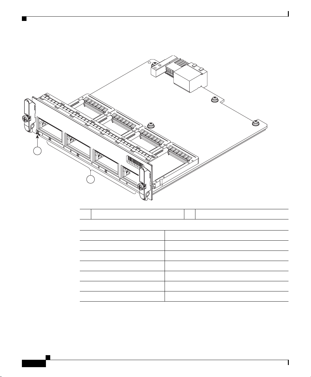
Figure 1-2 20-Port 1 GE RJ-45 (WS-X4920-GB-RJ45=)
1
2
Catalyst 4900M Switch Applications
78-18350-01
232118
1 Module Status LED 2 Port LEDs
Specification Description
Module type 10/100/1000BASE-T Fast Ethernet switching module
Port duplex mode Half or full duplex mode
Port speed 10, 100, or 1000 Mbps
Number of ports 20
Connector type RJ-45
Cable type Category 5
Power over Ethernet Not supported
Cisco Catalyst 4900M Switch Installation Guide
1-3
Page 24
Chapter 1 Product Overview
Catalyst 4900M Switch Applications
Figure 1-3 4-Port X2 Wire Speed 10 Gigabit Ethernet (WS-X4904-10GE=)
1
2
232119
1 Module Status LED 2 Port LEDs
Specification Description
Module type 10 Gigabit X2 fiber Ethernet switching module
Port duplex mode Full duplex mode
Port speed 10 Gbps
Number of ports 4
Connector type SC type
Cable type MMF or SMF
1-4
Cisco Catalyst 4900M Switch Installation Guide
78-18350-01
Page 25
Chapter 1 Product Overview
Catalyst 4900M Switch Applications
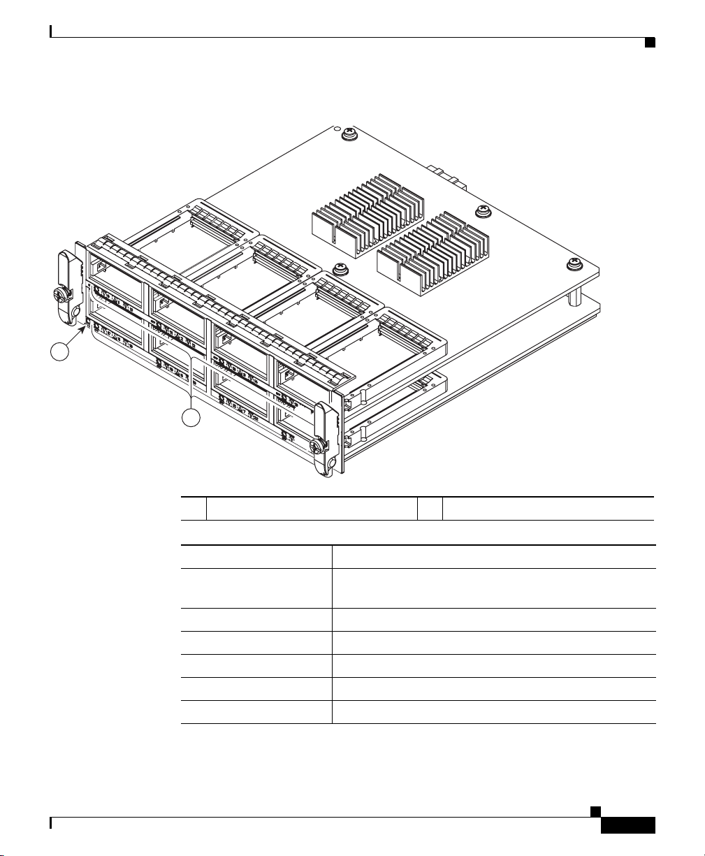
Figure 1-4 8-Port X2 2:1 Oversubscribed 10 Gigabit Ethernet (WS-X4908-10GE=)
1
2
232120
1 Module Status LED 2 Port LEDs
Specification Description
Module type 10 Gigabit X2 or TwinGig fiber Ethernet switching
module
Port duplex mode Full duplex mode
Port speed 10 Gbps or 2 Gbps
Number of ports 8
Connector type SC type
Cable type MMF or SMF
78-18350-01
Cisco Catalyst 4900M Switch Installation Guide
1-5
Page 26

Catalyst 4900M Switch Software Features
Note When using TwinGig and X2 transceivers on this module, keep them grouped in
pairs as follows: 1-2, 3-4, 5-6, 7-8. Inserting a TwinGig or X2 transciever in any
port will affect the capabilities of its partner port, and both will be set to handle
the same type automatically. Mixing within a port group will not work. As an
example, you would not be able to have an X2 in port 1 and a TwinGig in port 2
and expect both of them to function.
The Catalyst 4900M switch has a 320-Gbps, nonblocking, full-duplex switching
fabric, providing 250 million packets-per-second of switching capacity for
high-speed applications. The Catalyst
Ethernet ports and other ports as configured.
A removable automatic variable speed fan tray for low-noise operation at room
temperature and removable and redundant 1000
supplies provide fault-tolerance protection for the switch. See the
Power to the Catalyst 4900M Switch” section on page 3-11.
Chapter 1 Product Overview
4900M chassis has eight 10 Gigabit
W AC or 1000 W DC power
“Connecting
Catalyst 4900M Switch Software Features
For up-to-date information on software features, refer to the release notes and
software configuration guide for your software release.
Hardware System Features
The Catalyst 4900M switch is a high-performance dedicated Ethernet switch that
fully integrates into the Catalyst family of switches using Catalyst 4500 series
system software.
The following is an overview of the Catalyst 4900M hardware features:
• Eight 10 Gigabit Ethernet uplink ports using X2 interfaces
• Serial console management port using an RJ-45 interface
• A removable automatic variable speed fan tray for low-noise operation at
room temperature
• Redundant and removable 1000 W AC or DC power supplies
Cisco Catalyst 4900M Switch Installation Guide
1-6
78-18350-01
Page 27

Chapter 1 Product Overview
• 512-MB SDRAM (fixed)
• 128-MB embedded Flash memory
• 360-Gbps switching capacity, 250 million packets-per-second actual
forwarding rate
• EtherChannel at 10/100/1000 Mbps, as well as 10 Gbps
• Host and device USB 2.0 ports
• Compact flash memory slot
Switch Components
This section describes the Catalyst 4900M hardware components.
Traffic Ports
There are eight 10-Gigabit Ethernet uplink ports using X2 interfaces and other
traffic ports depending on the switching modules installed.
Switch Components
TwinGig Modules
On the WS-4908-10GE modules only, TwinGig converter modules may be used
in place of X2 modules if you need to provide 1 GB SFP connections. When you
insert the TwinGig into one port, its neighbor automatically converts to 1 GE
interfaces whether it has a TwinGig installed or not, so you need to group your
TwinGigs next to one another. The neighboring port to a TwinGig port cannot
support an X2.
Installation documentation for Cisco TwinGig converter modules can be found at:
http://www.cisco.com/en/US/docs/switches/lan/catalyst3750e_3560e/hardware/i
nstall/notes/1757202.html
78-18350-01
Cisco Catalyst 4900M Switch Installation Guide
1-7
Page 28

Switch Components
Rear Chassis Connections and Features
The Reset button is used to restart the switch. Use a paper clip or other small,
pointed object to press the Reset button.
A console serial port (RJ-45) provides for switch management using standard
console equipment. (See
Appendix A, “Specifications,” for the console and management ports.
The Management port on the rear panel offers the same TCP/IP based
management services available via inband access (telnet SNMP etc.). IP address
configuration via BOOTP is supported on the Management port; it also supports
image download to the switch.
A USB connector is provided for future expansion.
The Compact Flash port accepts both 64-MB and 128-MB Type 1 compact Flash
cards. You can use it for file transfer tasks such as loading a new software image.
The Flash card is optional and can be obtained from third-party suppliers.
For more information, refer to Using the Compact Flash on the Catalyst 4500
Series Supervisor Engines at the following URL:
http://www.cisco.com/en/US/docs/switches/lan/catalyst4500/hardware/configura
tion/notes/OL_2788.html
Figure 1-5.) A connector pinout table is provided in
Chapter 1 Product Overview
1-8
Cisco Catalyst 4900M Switch Installation Guide
78-18350-01
Page 29
Chapter 1 Product Overview
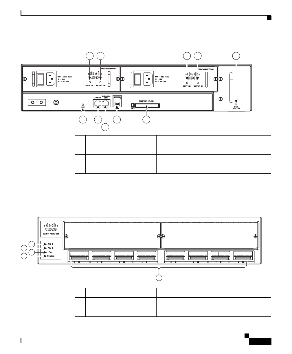
Figure 1-5 View of the Rear Panel
1 2 1 2 3
4 5 7 8
6
1 Input OK (power supply) 5 Console port
2 Output OK (power supply) 6 Management port
3 Fan Status LED 7 USB connection
4 Reset button 8 Compact Flash slot
Switch Components
232122
Front Panel LEDs
Figure 1-6 Front LEDs
1
2
3
4
1 PS1 LED 4 System LED
2 PS2 LED 5 10Gig port LEDs
3 Fan LED
78-18350-01
5
Cisco Catalyst 4900M Switch Installation Guide
232123
1-9
Page 30

Switch Components
Chapter 1 Product Overview
The LEDs on the front and rear panel of the Catalyst 4900M switch (see
Figure 1-5 and Figure 1-6 ) provide status information as follows:
• System LED indicates the operating state of the Catalyst 4900M switch.
• PS1 LED indicates the internal power supply status.
• PS2 LED indicates the internal power supply status.
• FAN LED indicates the fan tray status.
• A link status LED is below the 10-GB uplink ports.
A description of the LED functions is provided in Ta ble 1-1.
Ta b l e 1-1 LED Descriptions
LED Color or State Description
System
(front)
CON
(rear)
Green
Red
Flashing
Yel low
Off
Green
Off
At startup, the Catalyst 4900M performs a
series of diagnostic tests:
All tests pass
A test other than an individual port test fails
System boot or diagnostic tests in progress
System is in rommon mode or a power supply
has failed
Switch is disabled
10/100 BASE-T console port is in link-up
state
10/100 BASE-T console port is in link-down
state or not connected
1-10
MGT
Green
(rear)
Off
Cisco Catalyst 4900M Switch Installation Guide
There are no blinking, red, or yellow states
for this port
10/100/1000BASE-T Management port is in
link-up state
10/100/1000BASE-T Management port is in
link-down state or not connected
There are no blinking, red, or yellow states
for this port
78-18350-01
Page 31

Chapter 1 Product Overview
Table 1-1 LED Descriptions (continued)
LED Color or State Description
Port
(front)
Fan (front
and rear)
PS1 and
PS2
(front)
1. If either LED is green and the other is OFF the power supply is probably not plugged in. If it is
Switch Components
Green
Yel low
Flashing yellow
Off
Off
Green
Red
Off
Green
Red
red, the supply is either plugged in and not switched on or it is faulty. It may be necessary to
interrogate the system for further status using the CLI.
Port is operational
Port is disabled by user
Power-on self-test indicates faulty port
No signal detected or link configuration
failure
No power to the switch or fans (the tray may
not be plugged in especially if one or more of
the power supplies status LED is green)
Fan tray operational
Fault detected
No power to the PS
Operational1
Fault detected or the on/off switch is set to
off while the power supply is plugged in
Chassis Cooling
Note For environmental specifications, see Chapter 2, “Site Planning.”
The hot-swappable system fan tray provides cooling air for the internal chassis
components. The fans exhaust air to the left, and fresh air is drawn in from the
right side of the chassis.
Caution When the fan tray is removed, internal circuitry is exposed that should not be
touched by tools or fingers. The system should not be left operating without a fan
tray for longer than is necessary to replace a faulty fan tray with a new one.
Figure 1-7 shows the direction of airflow going in and out of the switch.
78-18350-01
Cisco Catalyst 4900M Switch Installation Guide
1-11
Page 32

Switch Components
Figure 1-7 Catalyst 4900M Airflow
Chapter 1 Product Overview
232124
There are five fans in the fan tray. If an individual fan fails, the other fans continue
to run. Sensors monitor the internal air temperatures. The number of fans in
operation and their speed varies according to the internal temperature for the
quietest operation possible. If the air temperature exceeds a desired threshold, the
environmental monitor displays warning messages.
Power Supplies
Note For complete power specifications for the Catalyst 4900M switch, see
Appendix A, “Specifications.”
Cisco Catalyst 4900M Switch Installation Guide
1-12
78-18350-01
Page 33

Chapter 1 Product Overview
The Catalyst 4900M switch has two redundant internal 1000 W AC or
1000
The internal power supplies have individual power cords and status LEDs (PS1
and PS2 on the front panel). There are also LEDs on the power supplies that show
status for the input (Input OK) and output (Output OK) currents. A power cord is
used to connect the power supplies to the site AC power source. There is a power
switch on the AC Catalyst
when a power cord is plugged into a power supply and the switch is set to the On
position. DC power supplies do not use a power supply cord or have an on/off
switch.
The switch starts with only one power supply plugged in, but redundant failover
and load sharing is not available in this configuration. Cisco recommends that you
always connect both power supplies to separate AC or DC circuits for optimal
power reliability.
For safety reasons, the AC power supply must be switched off and unplugged
before it is removed from a chassis or inserted into a chassis. DC supplies should
have power shut off from the source before they are removed.
If only one power supply is used, you must use the blank faceplate supplied to
cover the empty power bay.
Switch Components
W DC power supplies.
4900M switch power supplies; AC power is present
Environmental Monitoring of the Power Supplies
Using the environmental monitoring and reporting functions, you can maintain
normal system operation by resolving adverse environmental conditions prior to
loss of operation.
Each power supply monitors its own temperature and output voltages. The
Catalyst
reports status through software.
4900M switch senses the operating condition of the power supply and
Power Management for the Catalyst 4900M Switch
You can select AC or DC power supplies for your switch. The Catalyst 4900M
switch supports the following power supplies:
• 1000 W AC
• 1000 W DC
Cisco Catalyst 4900M Switch Installation Guide
78-18350-01
1-13
Page 34

Switch Components
A redundant power supply can be identified and diagnosed by a running system
regardless of its input status. AC and DC supplies are interchangeable.
Power Management Modes
The Catalyst 4900M switch supports the redundant power management mode. In
this mode, if both power supplies are operating normally, each provides from
20/80 to 45/55 percent of the total system power requirements at all times. If one
power supply fails, the other unit increases power to 100 percent of the total power
requirement.
Chapter 1 Product Overview
1-14
Cisco Catalyst 4900M Switch Installation Guide
78-18350-01
Page 35

Chapter 1 Product Overview
Serial Number Location
Figure 1-8 shows the location of the serial number for your switch.
Figure 1-8 Catalyst 4900M Serial Number
Serial Number Location
78-18350-01
202519
SN: XXXNNNNXXXX
Cisco Catalyst 4900M Switch Installation Guide
1-15
Page 36

Serial Number Location
Chapter 1 Product Overview
1-16
Cisco Catalyst 4900M Switch Installation Guide
78-18350-01
Page 37

CHAPTER
Site Planning
This chapter describes how to prepare your site for installation of the
Catalyst
• Site Environmental Requirements, page 2-1
• Site Power Requirements, page 2-2
• Grounding Requirements, page 2-4
• Safety Overview, page 2-5
• Site Planning Checklist, page 2-7
Note A site planning checklist is provided on page 2-8 to help ensure that you complete
all site planning activities before you install the switch.
Site Environmental Requirements
4900M switch and contains these sections:
2
78-18350-01
Planning a proper location for the switch and layout for your equipment rack or
wiring closet is essential for successful system operation. You should install the
switch in an enclosed, secure area, ensuring that only qualified personnel have
access to the switch and control of the environment. Equipment that is placed too
closely together or that is inadequately ventilated can cause system
overtemperature conditions. In addition, poor equipment placement can make
chassis panels inaccessible and difficult to maintain.
Cisco Catalyst 4900M Switch Installation Guide
2-1
Page 38

Site Power Requirements
The switch operates as a standalone system mounted in a rack in a secure wiring
closet. It requires a dry, clean, well-ventilated, and air-conditioned environment.
To ensure normal operation, maintain ambient airflow. If the airflow is blocked or
restricted, or if the intake air is too warm, an overtemperature condition can occur.
The switch environmental monitor can then shut down the system to protect the
system components.
To ensure normal operation and avoid unnecessary maintenance, plan your site
configuration and prepare your site before installation. After installation, make
sure that the site maintains an ambient temperature of 0 to 40° C (32 to 104° F). It
is essential to keep the area around the chassis as free from dust and foreign
conductive material (such as metal flakes from nearby construction activity) as is
possible.
Multiple switches can be rack-mounted with little or no clearance above and
below the chassis. However, when mounting a switch in a rack with other
equipment, or when placing it on the floor near other equipment, ensure that the
exhaust from other equipment does not blow into the intake vents of the chassis.
Cooling air is drawn in through the right side and exhausted through the left side
of the chassis. Keep the sides and rear clear of obstructions, including dust and
foreign conductive material, and away from the exhaust ports of other equipment.
Appendix A, “Specifications,” lists the operating and nonoperating environmental
site requirements for the switches. To maintain normal operation and ensure high
system availability, maintain an ambient temperature and EMI-free and
continuous power at your site. The environmental ranges listed in
those within which the switch will continue to operate; however, a measurement
that approaches the minimum or maximum of a range indicates a potential
problem. You can maintain normal operation by anticipating and correcting
environmental anomalies before they exceed the maximum operating range.
Chapter 2 Site Planning
Appendix A are
Site Power Requirements
This section describes the installation site power requirements for the
Catalyst
This section consists of the following sections:
• Preinstallation Requirements, page 2-3
• Warnings and Cautions, page 2-3
Cisco Catalyst 4900M Switch Installation Guide
2-2
4900M switch. Verify your site power before you install the switch.
78-18350-01
Page 39

Chapter 2 Site Planning
• EMI Recommendations, page 2-4
• Power Requirements and Heat Dissipation, page 2-4
Preinstallation Requirements
Follow these requirements when preparing your site for the Catalyst 4900M
switch installation:
• Connect each switch to separate wiring on a dedicated circuit; provide each
switch with its own branch circuit connection with sufficient overcurrent
protection and direct grounding to the branch circuit.
• To prevent a loss of input power, be sure the total maximum load on each AC
circuit is within the current ratings of the wiring and breakers.
Warnings and Cautions
Follow these precautions when preparing your site for the Catalyst 4900M switch
installation:
Site Power Requirements
78-18350-01
Caution The total maximum load on each AC or DC -input power circuit must be within
the rating of the wiring and breaker. An overload of input power can result if this
requirement is not met.
Warning
Warning
Warning
Read the installation instructions before connecting the system to the power
source.
Installation of the equipment must comply with local and national electrical
codes.
Ultimate disposal of this product should be handled according to all national
laws and regulations.
Statement 1004
Statement 1074
Statement 1040
Cisco Catalyst 4900M Switch Installation Guide
2-3
Page 40

Grounding Requirements
EMI Recommendations
Follow these guidelines when setting up the site wiring. When planning the
location of the new system, consider electromagnetic interface (EMI), the
distance limitations for signaling, and connector compatibility.
When wires are run for any significant distance in an electromagnetic field, radio
frequency interference (RFI) can occur between the field and the signals on the
wires.
• Bad plant wiring can result in radio frequency interference.
• Strong EMI, especially when caused by lightning or radio transmitters, can
destroy the signal drivers and receivers in the switch and can create an
electrical hazard by conducting power surges through lines and into
equipment.
Note To predict and remedy strong EMI, you might need to consult RFI experts.
Chapter 2 Site Planning
Power Requirements and Heat Dissipation
The power requirements might be useful for planning the power distribution
system needed to support the switches. Heat dissipation is an important
consideration for sizing the air-conditioning requirements for an installation.
Refer to
Catalyst 4900M switch.
Appendix A, “Specifications,” for the power and heat ratings for a
Grounding Requirements
Grounding is recommended on all AC or DC installations, using only approved
copper connectors. Attach the provided two hole ground lug to the chassis using
M4x 8mm bolts and then to the central office (CO) or other interior ground system
with number 6
as shown in
Cisco Catalyst 4900M Switch Installation Guide
2-4
AWG wire. The grounding connector is on the rear of the chassis,
Figure 2-1.
78-18350-01
Page 41

Chapter 2 Site Planning
Figure 2-1 Grounding Pad Location
1
1 Grounding pad
Safety Overview
This section provides safety information that you should read and understand to
ensure a safe switch installation.
Safety Overview
232131
Ensuring Safety
Follow these guidelines to ensure your safety and protect the equipment. This list
is not inclusive of all potentially hazardous situations that you may be exposed to
as you install the switch, so be alert.
Warning
Warning
78-18350-01
Only trained and qualified personnel should be allowed to install, replace, or
service this equipment.
This equipment must be grounded. Never defeat the ground conductor or
operate the equipment in the absence of a suitably installed ground conductor.
Contact the appropriate electrical inspection authority or an electrician if you
are uncertain that suitable grounding is available.
Statement 1030
Statement 1024
Cisco Catalyst 4900M Switch Installation Guide
2-5
Page 42

Safety Overview
Note To completely de-energize the system, unplug the power cord.
Chapter 2 Site Planning
• Always use caution when lifting heavy equipment. See the “Lifting the
Chassis Safely” section on page 3-4 before lifting the Catalyst 4900M switch.
• Always turn all power supplies off by unplugging all power cords before
installing or removing a chassis.
• Keep the chassis area clear and free of dust during and after installation.
• Keep tools and chassis components off of the floor and away from foot traffic.
• Avoid wearing jewelry (including rings and chains) or other items that could
get caught in the chassis. Avoid wearing any loose clothing, or securely fasten
items such as ties, scarves, or sleeves.
• Install the system in compliance with the following local and national
electrical codes:
–
United States—National Fire Protection Association (NFPA 70); United
States National Electrical Code
–
Canada—Canadian Electrical Code, Part I, CSA C22.1
–
Other countries—International Electrotechnical Commission (IEC)
60364, Part 1 through Part 7
Working Safely with Electricity
Follow these basic guidelines when working with any electrical equipment:
• Locate the emergency power-off switch for the room in which you are
working before beginning installation.
• Disconnect all power and external cables before installing or removing a
chassis.
• Do not work alone when potentially hazardous conditions exist.
• Never assume that power has been disconnected from a circuit; always check.
• Do not perform any action that creates a potential hazard to people or makes
the equipment unsafe.
Cisco Catalyst 4900M Switch Installation Guide
2-6
78-18350-01
Page 43

Chapter 2 Site Planning
• Examine your work area carefully for possible hazards such as moist floors,
ungrounded power extension cables, and missing safety grounds.
Preventing Electrostatic Discharge Damage
Electrostatic discharge (ESD) damage occurs when electronic cards or
components are improperly handled and can result in complete or intermittent
failures. Follow these guidelines to prevent ESD damage:
• Always use an ESD-preventive wrist or ankle strap, and ensure that it makes
maximum contact with the skin.
• When coming into contact with any internal components, always use a wrist
strap connected to one of the following:
–
ESD wrist strap connector
–
Any unpainted grounded surface on the chassis or equipment rack
Caution Periodically check the resistance value of the antistatic strap. The measurement
should be between 1 and 10 megohms (Mohms).
Site Planning Checklist
• Handle cards by the edges only.
• Avoid contact between the modules and clothing. The wrist strap protects
only the card from ESD voltages on the body; ESD voltages on clothing can
still cause damage.
Site Planning Checklist
Table 2-1 lists the site planning activities that you should perform before you
install the Catalyst 4900M switch. Completing each activity helps to ensure a
successful switch installation.
78-18350-01
Cisco Catalyst 4900M Switch Installation Guide
2-7
Page 44

Chapter 2 Site Planning
Site Planning Checklist
Ta b l e 2-1 Site Planning Checklist
Task No. Planning Activity Verified By Time Date
1 Space evaluation:
Space and layout
Floor covering
Shock and vibration
Lighting
Maintenance access
2 Environmental evaluation:
Ambient temperature
Humidity
Altitude
Atmospheric contamination
Airflow
3 Power evaluation:
Input power type
Receptacle proximity to the equipment
Dedicated (separate) circuits for redundant power
supplies
UPS for power failures
4 Grounding evaluation:
Circuit breaker size
5 Cable and interface equipment evaluation:
Cable type
Connector type
Cable distance limitations
Interface equipment (transceivers)
6 EMI evaluation:
2-8
Distance limitations for signaling
Site wiring
RFI levels
Cisco Catalyst 4900M Switch Installation Guide
78-18350-01
Page 45

CHAPTER
3
Installing the Switch
This chapter describes how to install the Catalyst 4900M switch. For first-time
installations, perform the procedures in the following sections in the order listed.
• Checking the Contents, page 3-1
• Rack-Mounting the Switch, page 3-2
• Connecting Power to the Catalyst 4900M Switch, page 3-11
• Connecting DC Power to the Catalyst 4900M Switch, page 3-13
• Optical Connections, page 3-15
• Configurable Modules, page 3-15
Note Before starting the installation procedures in this chapter, complete the site
planning checklist in
activities were completed.
Chapter 2, “Site Planning,” to verify that all planning
Checking the Contents
Note Do not discard the shipping container when you unpack the switch. Flatten the
shipping cartons and store them. You will need the container if you need to move
or ship the switch in the future.
78-18350-01
Cisco Catalyst 4900M Switch Installation Guide
3-1
Page 46

Rack-Mounting the Switch
To check the contents of the shipping container follow these steps:
Step 1 Check the contents of the accessories kit against the packing slip. Verify that you
received all listed equipment, which should include the following:
• Switch hardware and software documentation, if ordered
• Optional equipment that you ordered, such as network interface cables,
transceivers, or special connectors
Step 2 To begin installation, proceed to the “Rack-Mounting the Switch” section on
page 3-2.
Rack-Mounting the Switch
A standard rack-mount kit is included for mounting the switch in a standard
19-inch (48.3
unobstructed front posts, a minimum depth between the front and rear mounting
posts of 19.25
This kit is not suitable for racks with obstructions (such as a power strip) that
could impair access to the switch.
cm) four-post equipment rack. A standard equipment rack has two
inches (48.9 cm), and a maximum depth of 32 inches (81.3 cm).
Chapter 3 Installing the Switch
3-2
A separate mounting kit for a two-post telco rack is available, and differs mainly
in the dimensions and in the absence of the rear mounts.
Caution Before installing the chassis in a rack, read the “Site Environmental
Requirements” section on page 2-1 to become familiar with the proper site and
environmental conditions. Failure to read and follow these guidelines could lead
to an unsuccessful installation and possible damage to the system and
components.
Caution This unit is meant to be rack-mounted, and is not intended to bear more than its
own weight. Do not stack more than two on a table top, the added weight may
damage the bottom chassis.
Cisco Catalyst 4900M Switch Installation Guide
78-18350-01
Page 47

Chapter 3 Installing the Switch
Rack-Mounting the Switch
Warning
To prevent bodily injury when mounting or servicing this unit in a rack, you
must take special precautions to ensure that the system remains stable. The
following guidelines are provided to ensure your safety:
• This unit should be mounted at the bottom of the rack if it is the only unit in the rack.
• When mounting this unit in a partially filled rack, load the rack from the bottom to the
top with the heaviest component at the bottom of the rack.
• If the rack is provided with stabilizing devices, install the stabilizers before mounting
or servicing the unit in the rack.
Rack-Mounting Guidelines
Before rack-mounting the switch, ensure the following:
• The equipment rack is the proper size.
–
The width of the rack, between the two front mounting strips or rails,
must be 17.75
–
The depth of the rack, between the front and rear mounting strips, must
be at least 19.25
–
The rack must have sufficient vertical clearance to insert the chassis. The
chassis height is 1.75 inches (4.45 cm).
• The equipment rack is stable and in no danger of falling over.
Statement 1006
inches (45.09 cm).
inches (48.9 cm) but not more than 32 inches (81.3 cm).
78-18350-01
–
Ensure that the shelf is constructed to support the weight and dimensions
of the chassis. For physical specifications, see
Appendix A,
“Specifications.”
–
We recommend that you bolt the rack to the floor.
–
Mount the unit at the bottom of the rack if it is the only unit in the rack.
–
Install heavier equipment in the lower half of the rack to maintain a low
center of gravity and prevent the rack from becoming top-heavy and
tipping over.
–
Install the stabilizers before mounting or servicing the switch in the rack
(if the rack is provided with stabilizing devices).
Cisco Catalyst 4900M Switch Installation Guide
3-3
Page 48

Rack-Mounting the Switch
• The equipment rack is properly ventilated.
Chapter 3 Installing the Switch
–
Install the chassis in an enclosed rack only if it has adequate ventilation
or an exhaust fan; use an open rack whenever possible.
–
Ensure that the ambient temperature of the rack environment does not
exceed a maximum temperature of 104° F (40° C). Note that if the switch
is installed in a closed or multiunit rack assembly, the ambient operating
temperature of the rack environment might be higher than the ambient
room temperature.
–
Note that a ventilation system in a closed rack that is too powerful might
also prevent cooling by creating negative pressure around the chassis and
redirecting the air away from the chassis intake vent. If necessary,
operate the chassis with the rack open.
–
To prevent airflow restriction, allow at least 3 inches (7.6 cm) of
clearance around the ventilation openings on the sides of the chassis.
–
Use baffles correctly to assist in cooling the chassis.
–
Note that equipment near the bottom of a rack may generate excessive
heat that is drawn upward and into the intake ports of equipment above,
leading to overtemperature conditions in the chassis at or near the top of
the rack.
–
Consider the equipment and cabling that is already installed in the rack.
Ensure that cables from other equipment will not obstruct the airflow
through the chassis or impair access to the power supplies or switching
modules. Route cables away from field-replaceable components to avoid
disconnecting cables unnecessarily for equipment maintenance or
upgrades.
–
Allow at least 3 to 4 feet (91.4 to 121.9 cm) of clearance behind the rack
for maintenance and removal of switch assemblies. If the rack is mobile,
you can push it back within 1 foot (30.45 cm) of a wall or cabinet for
normal operation and pull it out when necessary for maintenance.
Lifting the Chassis Safely
The chassis is not intended to be moved frequently. Before you install the switch,
ensure that your site is properly prepared so that you can avoid moving the chassis
later to accommodate power sources and network connections.
Cisco Catalyst 4900M Switch Installation Guide
3-4
78-18350-01
Page 49

Chapter 3 Installing the Switch
Whenever you lift a chassis or any heavy object, follow these guidelines:
• Ensure that your footing is solid, and balance the weight of the chassis
• Lift the chassis slowly; never move suddenly or twist your body as you lift.
• Keep your back straight and lift with your legs, not your back. If you must
• Always disconnect all external cables before lifting or moving the chassis.
Figure 3-1 Unsafe Lifting Practices
Rack-Mounting the Switch
between your feet.
bend down to lift the chassis, bend at the knees, not at the waist, to reduce the
strain on your lower back muscles. (See
Figure 3-1.)
Required Installation Tools
The following tools and equipment are required to install the chassis:
• Number 1, number 2 Phillips, and 3/16-inch flat-blade screwdriver
• Antistatic mat or antistatic foam
• Your own ESD grounding strap or the disposable ESD strap included with the
system
The following tools and equipment are required to install the chassis in a rack:
• Rack-mount kit
78-18350-01
H1369a
Cisco Catalyst 4900M Switch Installation Guide
3-5
Page 50

Rack-Mounting the Switch
• Tape measure and level
Rack-Mounting the Catalyst 4900M Switch
Follow these steps to install the Catalyst 4900M switch in a four-post rack.
Step 1 Prepare for installation:
a. Place the chassis on the floor or on a sturdy table as close as possible to the
rack. Leave enough clearance to allow you to move around the chassis.
b. Use a tape measure to measure the depth of the rack. Measure from the
outside of the front mounting posts to the outside of the rear mounting strip.
The depth must be at least 19.0
28
inches (71.1 cm).
c. Measure the space between the inner edges of the left front and right front
mounting posts to ensure that it is 17.75
is 17.5
inches [44 cm] wide and must fit between the mounting posts.)
d. Open the rack-mount kit, and refer to the component checklist to verify that
all parts are included.
inches (48.2 cm) but not greater than
inches (45.09 cm) wide. (The chassis
Chapter 3 Installing the Switch
3-6
Ta b l e 3-1 Rack-Mount Kit Checklist
Quantity Part Description Received
2 L brackets
12 M4 Phillips Flat-head screws
4 12-24 x 3/4-inch Phillips binder-head screws
4 10-32 x 3/4-inch Phillips binder-head screws
Note Figure 3-2 illustrates how to attach the front of the switch to the rack. You
will also need to attach the rear of the switch to the rack.
Step 2 Note that the L brackets connect the chassis to the rack. You can mount the
L
brackets to the front or rear mounting holes of the chassis, depending on which
end is in the front of the rack.
Cisco Catalyst 4900M Switch Installation Guide
78-18350-01
Page 51

Chapter 3 Installing the Switch
Note Some equipment racks provide a power strip along the length of one of
the rear posts. If the rack has this feature, consider the position of the strip
when planning fastener points. Before installing the L brackets on the
chassis, determine whether to install the chassis from the front or the rear
of the rack.
Attach the left and right L brackets using the four M4 Phillips pan-head screws
provided in the rack-mount kit. (See
the front bracket.
Figure 3-2 Attaching the L Brackets to the Switch
Rack-Mounting the Switch
Figure 3-2.) Then slide the rear bracket into
78-18350-01
202519
Cisco Catalyst 4900M Switch Installation Guide
232125
3-7
Page 52

Rack-Mounting the Switch
Step 3 Install the chassis in the rack as follows:
a. Position the chassis in the rack (see Figure 3-3):
b. Align the mounting holes in the front and rear L brackets with the mounting
c. Secure the chassis using eight (two on each flange) 12-24 x 3/4-inch screws
d. Use a tape measure and level to ensure that the chassis is installed straight and
Chapter 3 Installing the Switch
–
If the chassis front panel is in the front of the rack, insert the rear of the
chassis between the mounting posts.
–
If the rear of the chassis is in the front of the rack, insert the front of the
chassis between the mounting posts.
holes in the equipment rack.
through the elongated holes in the L brackets and into the threaded holes in
the mounting posts.
level.
3-8
Cisco Catalyst 4900M Switch Installation Guide
78-18350-01
Page 53

Chapter 3 Installing the Switch
Figure 3-3 Installing the Switch in the Rack
Rack-Mounting the Switch
78-18350-01
202519
232126
Step 4 Attach the cable guide to the right or left side of the chassis mount.
Cisco Catalyst 4900M Switch Installation Guide
3-9
Page 54

Rack-Mounting the Switch
Figure 3-4 Installing the Cable Guide
Chapter 3 Installing the Switch
232127
3-10
Step 5 Do not connect the power cord at this time. Proceed to the “Connecting Power to
the Catalyst 4900M Switch” section on page 3-11.
Cisco Catalyst 4900M Switch Installation Guide
78-18350-01
Page 55

Chapter 3 Installing the Switch
Connecting Power to the Catalyst 4900M Switch
Connecting Power to the Catalyst 4900M Switch
Follow these steps and warnings when connecting power to the Catalyst 4900M
switch:
Step 1 Prior to connecting the power supply to a power source, ensure that all of the site
power and grounding requirements described in
been met and the chassis is properly grounded as described in the “Grounding
Requirements” section on page 2-4. The grounding pad for the switch is shown in
Figure 3-5.
Figure 3-5 Grounding Pad Location
Chapter 2, “Site Planning,” have
1
78-18350-01
1 Grounding pad
Warning
Step 2 Plug the power cords into the power supplies. Refer to Figure 3-6 for the plug
The plug-socket combination must be accessible at all times because it serves
as the main disconnecting device.
Statement 1019
location.
Cisco Catalyst 4900M Switch Installation Guide
232131
3-11
Page 56

Connecting Power to the Catalyst 4900M Switch
Figure 3-6 AC Power Supply
Chapter 3 Installing the Switch
2 2
1
3
4
5 6
1
232129
1 Captive screw 4 AC power connection
2 Handle 5 INPUT OK LED
3 On/off switch 6 OUTPUT OK LED
Step 3 Connect the other end of the power cords to an AC-power input source. If both
power supplies will be used, make sure they are on different circuits.
Step 4 Turn the power switches to the ON position.
Step 5 Verify power supply operation by looking at the front panel power supply LEDs:
3-12
• The PS1 or PS2 LED is green when the power supply and fans are functioning
normally.
• The PS1 or PS2 LED is red when the power supply is not functioning
normally. The on/off switch may be set to off while the power supply is
plugged in, or the power supply may be defective and not providing DC
power to the switch. There may also be a fan failure.
• The PS1 or PS2 LED is off when there is no power supply installed.
From the system console, enter the show power command to display the power
supply and system status. For more information on this command, see the
command reference publication for your software release.
Cisco Catalyst 4900M Switch Installation Guide
78-18350-01
Page 57

Chapter 3 Installing the Switch
Connecting DC Power to the Catalyst 4900M Switch
If the LEDs or show power command indicate a power or other system problem,
see
Chapter 4, “Troubleshooting the Installation,” for troubleshooting
information.
Connecting DC Power to the Catalyst 4900M Switch
Follow these steps and warnings when connecting DC power to the
Catalyst
4900M switch:
Warning
Warning
Warning
Warning
Step 1 Prior to connecting the power supply to a power source, ensure that all of the site
Before performing any of the following procedures, ensure that power is
removed from the DC circuit.
This unit is intended for installation in restricted access areas. A restricted
access area can be accessed only through the use of a special tool, lock and
key, or other means of security.
This product requires short-circuit (overcurrent) protection, to be provided as
part of the building installation. Install only in accordance with national and
local wiring regulations.
Hazardous voltage or energy may be present on DC power terminals. Always
replace cover when terminals are not in service. Be sure uninsulated
conductors are not accessible when cover is in place.
power and grounding requirements described in
Statement 1003
Statement 1017
Statement 1045
Statement 1075
Chapter 2, “Site Planning,” have
been met and the chassis is properly grounded as described in the “Grounding
Requirements” section on page 2-4.
78-18350-01
Step 2 Remove the safety cover from the power terminal.
Step 3 Connect the power supply ground terminal to earth ground.
Cisco Catalyst 4900M Switch Installation Guide
3-13
Page 58

Connecting DC Power to the Catalyst 4900M Switch
Figure 3-7 DC Power Supply
Chapter 3 Installing the Switch
1
2 23
4
5 6
7
8
1
232130
1 Captive screw 5 Positive terminals
2 Handle 6 Negative terminals
3 On/off switch 7 INPUT OK LED
4 Ground terminal 8 OUTPUT OK LED
Step 4 Connect the positive and negative power cables into the power supplies using a
number 2 Phillips screwdriver.
Note The DC power cables may use AWG #10 to AWG #12 wire.
3-14
Step 5 Replace the safety cover over the power terminals.
Step 6 Connect the other end of the power cables to an DC-power input source. If both
power supplies will be used, make sure they are on different circuits.
Step 7 Turn on the power from the power source. Turn the DC supply on/off switch to
ON.
Step 8 Verify power supply operation by looking at the front panel power supply LEDs:
• The PS1 or PS2 LED is green when the power supply is functioning normally.
• The PS1 or PS2 LED is red when the power supply is not functioning
normally.
Cisco Catalyst 4900M Switch Installation Guide
78-18350-01
Page 59

Chapter 3 Installing the Switch
• The PS1 or PS2 LED is off when the power supply is not connected to a power
source.
From the system console, enter the show power command to display the power
supply and system status. For more information on this command, see the
command reference publication for your software release.
If the LEDs or show power command indicate a power or other system problem,
see
Chapter 4, “Troubleshooting the Installation,” for troubleshooting
information.
Optical Connections
The Cisco 4900M switch has up to 24 ports that can be configured with X2
modules with SC connectors. Module types supported are documented at:
http://www.cisco.com/en/US/products/hw/modules/ps5455/products_device_sup
port_table09186a00803857e7.html
Optical Connections
Generic connection instructions for the X2 modules are at:
http://www.cisco.com/en/US/docs/interfaces_modules/transceiver_modules/inst
allation/note/78_16705.html
Installation documentation for Cisco TwinGig converter modules can be found at:
http://www.cisco.com/en/US/docs/switches/lan/catalyst3750e_3560e/hardware/i
nstall/notes/1757202.html
Configurable Modules
All Catalyst 4900M modules support hot swapping, which lets you install,
remove, replace, and rearrange switching modules without turning off the system
power. When the system detects that a switching module has been installed or
removed, it runs diagnostic and discovery tests automatically, acknowledges the
presence or absence of the module, and resumes system operation with no
operator intervention.
78-18350-01
Cisco Catalyst 4900M Switch Installation Guide
3-15
Page 60

Configurable Modules
This section describes the following topics:
• Required Tools, page 3-16
• Removing Switching Modules, page 3-16
• Installing Switching Modules, page 3-19
Required Tools
You will need these tools to install supervisor engines and switching modules in
the Catalyst
• Number 1 and number 2 Phillips screwdrivers for the captive installation
• 3/16-inch flat-blade screwdriver for the captive installation screws on other
• Antistatic mat or antistatic foam
• Wrist strap or other grounding device
Chapter 3 Installing the Switch
4900M series switches:
screws on most modules
modules
Note Whenever you handle switching modules, use a wrist strap or other grounding
device to prevent ESD damage.
Removing Switching Modules
Warning
Warning
Cisco Catalyst 4900M Switch Installation Guide
3-16
Invisible laser radiation may be emitted from disconnected fibers or
connectors. Do not stare into beams or view directly with optical instruments.
Statement 1051
Hazardous voltage or energy is present on the backplane when the system is
operating. Use caution when servicing.
Statement 1034
78-18350-01
Page 61
Chapter 3 Installing the Switch
Configurable Modules
Warning
Voltages that present a shock hazard may exist on Power over Ethernet (PoE)
circuits if interconnections are made using uninsulated exposed metal
contacts, conductors, or terminals. Avoid using such interconnection methods,
unless the exposed metal parts are located within a restricted access location
and users and service people who are authorized within the restricted access
location are made aware of the hazard. A restricted access area can be
accessed only through the use of a special tool, lock and key or other means of
security.
Caution To prevent ESD damage, handle switching modules by the carrier edges only.
Statement 1072
To remove a switching module from a Catalyst 4900M series switch, follow this
procedure:
Step 1 Disconnect any network interface cables attached to the ports on the switching
module that you intend to remove.
Step 2 Loosen the captive installation screws. (See Figure 3-8.)
78-18350-01
Cisco Catalyst 4900M Switch Installation Guide
3-17
Page 62

Configurable Modules
Figure 3-8 Captive Installation Screws and Ejector Levers
2
1
Chapter 3 Installing the Switch
2
3-18
1
232517
1 Captive screw 2 Ejector lever
Step 3 Grasp the left and right ejector levers, and simultaneously pivot the levers
downward to release the switching module from the backplane connector.
Step 4 Grasp the front panel of the switching-module with one hand, and place your other
hand under the carrier to support and guide it out of the slot. Do not touch the
printed circuit boards or connector pins.
Step 5 Carefully pull the switching module straight out of the slot, keeping your other
hand under the carrier to guide it.
Step 6 Place the switching module on an antistatic mat or antistatic foam, or immediately
install it in another slot.
Cisco Catalyst 4900M Switch Installation Guide
78-18350-01
Page 63

Chapter 3 Installing the Switch
Step 7 If the slot is to remain empty, install a switching-module filler plate.
Configurable Modules
Warning
Blank faceplates and cover panels serve three important functions: they
prevent exposure to hazardous voltages and currents inside the chassis; they
contain electromagnetic interference (EMI) that might disrupt other equipment;
and they direct the flow of cooling air through the chassis. Do not operate the
system unless all cards, faceplates, front covers, and rear covers are in place.
Statement 1029
Installing Switching Modules
All Catalyst 4900M series supervisor engine modules and switching modules are
installed in horizontal chassis slots that are numbered from top to bottom.
Warning
Warning
Invisible laser radiation may be emitted from disconnected fibers or
connectors. Do not stare into beams or view directly with optical instruments.
Statement 1051
Voltages that present a shock hazard may exist on Power over Ethernet (PoE)
circuits if interconnections are made using uninsulated exposed metal
contacts, conductors, or terminals. Avoid using such interconnection methods,
unless the exposed metal parts are located within a restricted access location
and users and service people who are authorized within the restricted access
location are made aware of the hazard. A restricted access area can be
accessed only through the use of a special tool, lock and key or other means of
security.
Statement 1072
78-18350-01
Caution To prevent ESD damage, handle switching modules by the carrier edges only.
Cisco Catalyst 4900M Switch Installation Guide
3-19
Page 64

Configurable Modules
Step 1 Take the necessary precautions to prevent ESD damage as described in Appendix
Step 2 Choose a slot for the new switching module. Ensure that you have enough
Step 3 Loosen the captive installation screws that secure the switching-module filler
Step 4 Remove the switching-module filler plate (or the existing switching module).
Step 5 To install the new switching module, grasp the switching-module front panel with
Chapter 3 Installing the Switch
To install a switching module in a Catalyst 4900M series switch, follow this
procedure:
B and in Chapter 2.
clearance to accommodate any interface equipment that you will connect directly
to the switching module ports.
plate (or the existing switching module) to the desired slot.
Save the switching-module filler plate for future use. If you are removing an
existing switching module, see the
page 3-16.
one hand, and place your other hand under the carrier to support the switching
module, as shown in
Figure 3-9. Do not touch the printed circuit boards or
connector pins.
“Removing Switching Modules” section on
3-20
Step 6 Align the edges of the circuit board with the slot guides on the sides of the switch
chassis, as shown in
Cisco Catalyst 4900M Switch Installation Guide
Figure 3-9.
78-18350-01
Page 65

Chapter 3 Installing the Switch
Figure 3-9 Installing the Switching Module in the Chassis
1
Configurable Modules
78-18350-01
1
232516
1 Captive screw
Step 7 Carefully slide the switching module into the slot until both ejector levers engage
the chassis sides equally and the module is seated in the backplane.
Step 8 Use a screwdriver to tighten the captive installation screws on each end of the
switching module faceplate.
To check the status of the module, follow this procedure:
Step 1 Ensure that the STATUS LED is green (module operational).
Cisco Catalyst 4900M Switch Installation Guide
3-21
Page 66

Chapter 3 Installing the Switch
Removing and Replacing the Power Supply
Step 2 When the switch is online, enter the show module command. Verify that the
system acknowledges the new module and that the module’s status is listed as
good in the command output.
Step 3 If the module is not operational, reseat it. If the module is still not operational,
contact your customer service representative.
Removing and Replacing the Power Supply
This section describes how to remove and install the AC and DC-input power
supplies. This information is presented in the following sections:
• Required Tools, page 3-23
• Removing a Power Supply, page 3-23
• Installing a Power Supply, page 3-24
3-22
Warning
Hazardous voltage or energy is present on the backplane when the system is
operating. Use caution when servicing.
Statement 1034
Locate your power supply and notice the location of the captive installation
screws.
Note The power supplies are hot-swappable, so in redundant mode you will not need to
power down the switch to replace most power supplies. In combined mode some
slots may lose power during power supply replacement.
Cisco Catalyst 4900M Switch Installation Guide
78-18350-01
Page 67

Chapter 3 Installing the Switch
Required Tools
You will need a flathead or Phillips screwdriver to perform these procedures.
Removing a Power Supply
Follow these steps to remove a power supply:
Step 1 Set the power switch to the off (O) position.
Step 2 Disconnect the power cord or cords from the power supply being removed.
Step 3 Loosen the captive screws.
Caution Use both hands to remove a power supply.
Step 4 Grasp the power supply handles and pull the power supply out an inch to unseat
the backplane connections. Place one hand underneath to support the bottom of
the power supply.
Removing and Replacing the Power Supply
78-18350-01
Step 5 Pull the power supply out of the bay and set it aside.
Warning
Step 6 If the power supply bay is to remain empty, install a blank power supply filler
Blank faceplates and cover panels serve three important functions: they
prevent exposure to hazardous voltages and currents inside the chassis; they
contain electromagnetic interference (EMI) that might disrupt other equipment;
and they direct the flow of cooling air through the chassis. Do not operate the
system unless all cards, faceplates, front covers, and rear covers are in place.
Statement 1029
plate over the opening. Secure the filler plate with the two mounting screws and
tighten them with a screwdriver.
Cisco Catalyst 4900M Switch Installation Guide
3-23
Page 68

Removing and Replacing the Power Supply
Installing a Power Supply
Chapter 3 Installing the Switch
Warning
The plug-socket combination must be accessible at all times, because it serves
as the main disconnecting device.
Statement 1019
Follow these steps to install a power supply:
Step 1 Make sure that the power supply you are installing is not connected to a power
source and that a power cord is not connected to the power supply.
Step 2 Loosen the two Phillips-head screws from the power supply filler plate (if a filler
plate is present).
Step 3 Remove the power supply filler plate (if one is present) and set it aside.
Caution Use both hands to grasp a power supply.
Step 4 Grasp a power supply handle with one hand. Place your other hand underneath to
support the bottom of the power supply.
Step 5 Slide the power supply almost all the way into the power supply bay. Press with
both thumbs evenly to correctly seat the power supply into the connections inside.
Step 6 Using a screwdriver, tighten the two captive installation screws on the front panel
of the power supply.
Step 7 Make sure the power supply power switch is in the off position (O).
Step 8 Before you connect the power supply to a power source, ensure that all site power
and grounding requirements have been met.
Step 9 Plug the power cord or cords into the power supply.
3-24
Step 10 Connect the other end of the power cord to a power input source.
Caution In a system with multiple power supplies, connect each power supply to a separate
power source. In the event of a power source failure, if the second source is still
available, it can maintain maximum overcurrent protection for each power
connection.
Cisco Catalyst 4900M Switch Installation Guide
78-18350-01
Page 69

Chapter 3 Installing the Switch
Removing and Replacing the Fan Assembly
Step 11 Press the power switch to the on (|) position.
Step 12 Verify power supply operation by checking the power supply’s front-panel LEDs.
You should see the following:
• The LED labeled INPUT OK is green.
• The LED labeled OUTPUT OK is green.
Step 13 Check the power supply and system status from the system console by entering
show power command. For more information on this command, refer to the
command reference publication for your switch.
Step 14 If the LEDs or show power command output indicate a power problem or other
system problem, see
information.
Chapter 4, “Troubleshooting the Installation,” for more
Removing and Replacing the Fan Assembly
This section describes how to remove and install the fan assembly.
Required Tools
You will need a Phillips screwdriver for the following two procedures.
Removing the Fan Assembly
Warning
78-18350-01
When removing the fan tray, keep your hands and fingers away from the
spinning fan blades. Let the fan blades completely stop before you remove the
fan tray.
Statement 258
Cisco Catalyst 4900M Switch Installation Guide
3-25
Page 70

Removing and Replacing the Fan Assembly
Caution Never operate the system for an extended period if the fan assembly is removed
or if it is not functioning properly. An over-temperature condition can cause
severe equipment damage.
Follow these steps to remove the existing fan assembly:
Step 1 Loosen the two captive installation screws on the fan assembly by turning them
counterclockwise.
Step 2 Grasp the fan assembly with both hands and pull it outward; gently move it side
to side if necessary to unseat it from the backplane. Slide it out of the chassis and
place it in a safe place.
Installing the Fan Assembly
Follow these steps to install the new fan assembly:
Chapter 3 Installing the Switch
3-26
Step 1 Hold the fan assembly with the captive screws on the left.
Step 2 Place the fan assembly into the fan assembly bay so it rests on the chassis, and
then lift the fan assembly up slightly, aligning the top and bottom guides.
Step 3 Slide the fan assembly into the chassis until the two captive installation screws
make contact with the chassis.
Step 4 Using a screwdriver, tighten the two captive installation screws by turning them
clockwise.
Cisco Catalyst 4900M Switch Installation Guide
78-18350-01
Page 71

Chapter 3 Installing the Switch
Verifying the Installation
Note To check the operation of the fans, you need to power up the chassis.
Follow these steps to verify that the new fan assembly was installed correctly:
Step 1 Listen for the fans; you should immediately hear them operating. If you do not
hear them, ensure that the fan assembly is inserted completely in the chassis and
that the faceplate is flush with the switch back panel.
Step 2 The fan tray LED should light and be green.
Step 3 If after several attempts the fans do not operate, or if you experience trouble with
the installation (for instance, if the captive installation screws do not align with
the chassis holes), contact the Cisco TAC for assistance.
Removing and Replacing the Fan Assembly
78-18350-01
Cisco Catalyst 4900M Switch Installation Guide
3-27
Page 72

Removing and Replacing the Fan Assembly
Chapter 3 Installing the Switch
3-28
Cisco Catalyst 4900M Switch Installation Guide
78-18350-01
Page 73

CHAPTER
4
Troubleshooting the Installation
This chapter describes how to troubleshoot the Catalyst 4900M switch hardware
installation and contains these sections:
• Getting Started, page 4-1
• Problem Solving to the System Component Level, page 4-2
• Identifying Startup Problems, page 4-2
• Troubleshooting the Power Supply, page 4-5
• Contacting Customer Service, page 4-6
If your system has problems starting up, use the information in this chapter to help
isolate the cause. Problems with the initial startup are often caused by poor or
improper connections. Although temperature conditions above the maximum
acceptable level rarely occur at initial startup, environmental monitoring
functions are included because they also monitor DC-line voltages.
Note For configuration questions or problems, refer to the software configuration guide
or the command reference publication to configure or enable the interfaces.
Getting Started
When the initial system boot is complete, verify the following:
• Power supplies are supplying power to the system.
• The system fan assembly is operating.
78-18350-01
Cisco Catalyst 4900M Switch Installation Guide
4-1
Page 74

Chapter 4 Troubleshooting the Installation
Problem Solving to the System Component Level
• System software boots successfully.
If all of these conditions are met and the hardware installation is complete, refer
to the software configuration guide and the command reference publications to
troubleshoot the software. However, if any of these conditions are not met, use the
procedures in this chapter to isolate and, if possible, resolve the problem.
Problem Solving to the System Component Level
The key to success when troubleshooting the system is to isolate the problem to a
specific system component. The first step is to compare what the system is doing
to what it should be doing. Because a startup problem can usually be attributed to
a single component, it is more efficient to isolate the problem to a subsystem
rather than troubleshoot each separate component in the system.
The switch consists of the following subsystems:
• Power supply—Includes the power supply and power supply cooling. (See
the
“Troubleshooting the Power Supply” section on page 4-5.)
• Fan assembly system—The chassis fan assembly should operate whenever
system power is on. Usually, it continues to operate even when the
environmental monitor shuts down the system because of an overtemperature
or overvoltage condition. (It will shut down for a power supply shutdown.)
You should be able to hear the fan assembly to determine whether or not it is
operating. If the FAN LED is orange and you determine that the fan assembly
is not operating, you should immediately contact a customer service
representative. There are no installation adjustments that you can make if the
fan assembly does not function properly at the initial startup.
Identifying Startup Problems
When you connect the power cords to the Catalyst 4900M switch, follow these
steps:
Step 1 Flip the power switches to the on position (AC powered systems only).
Step 2 Verify that power is available to the power supplied from the site AC or DC
source. Flip breakers and fuses if necessary.
Cisco Catalyst 4900M Switch Installation Guide
4-2
78-18350-01
Page 75

Chapter 4 Troubleshooting the Installation
Step 3 Listen for the system fan assembly. If you do not immediately hear the system fan
assembly begin to operate, see
page 4-5.
Step 4 If you determine that the power supplies are functioning normally and that the fan
assembly is faulty, contact a customer service representative. If the system fan
assembly does not function properly at initial startup, there are no installation
adjustments that you can make.
LED Readings
LEDs indicate all system states in the startup sequence. By checking the LEDs,
you can determine when and where the system failed in the startup sequence. To
check the LEDs, follow these steps:
Step 1 Compare the LED states to Tab le 4-1:
Identifying Startup Problems
“Troubleshooting the Power Supply” section on
78-18350-01
Cisco Catalyst 4900M Switch Installation Guide
4-3
Page 76

Identifying Startup Problems
Ta b l e 4-1 Power Supply LED Meanings
LED and Color Meaning
INPUT OK (AC)
Chapter 4 Troubleshooting the Installation
This LED should turn green immediately when power is
applied to the supply and the power switch is set to ON.
Green
Red
Off
INPUT OK (DC)
Green
Red
Off
OUTPUT OK
Green
Red
AC input voltage is greater than 80.5 +/- 4.5 V AC.
In a dual power supply configuration (alternate unit
powered) the AC input is less than 73 +/-3V, or the power
supply is turned off.
In a single supply configuration, signals that AC input
voltage is less than 73 +/-3V, or the power supply is turned
off.
This LED should turn green immediately when power is
applied to the supply.
DC input voltage is greater than -38.25 +/-2.25V.
In a dual power supply configuration (alternate unit
powered) the DC input is less than 33 +/-3V, or the power
supply is turned off.
In a single supply configuration, the LED shall be off to
signal that DC input is less than 33 +/-3V, or the power
supply is turned off.
DC output voltages are within the normal operating range.
Output voltages below the minimum or above the
maximum will create an output fail alarm and cause the
LED to illuminate red.
4-4
Step 2 Verify that the LEDs on the front panel are lit:
• The STATUS LED flashes yellow during diagnostic boot tests. It is green
when the switch is operational (online). If the system software is unable to
start up, this LED stays orange.
Cisco Catalyst 4900M Switch Installation Guide
78-18350-01
Page 77

Chapter 4 Troubleshooting the Installation
• The port LEDs (1-48) are green when the module is operational (online). If
no signal is detected, the LINK LED is off. The port LED remains yellow if
the port is disabled. The port LED flashes yellow if the port tested faulty at
startup.
Step 3 If a STATUS LED is red, contact a customer service representative for
instructions.
Step 4 If the boot information and system banner are not displayed, verify that the
terminal is set correctly and that it is connected properly to the console port.
Troubleshooting the Power Supply
Follow these steps to help isolate a power subsystem problem:
Step 1 Verify that the power supply is plugged in and that the on/off switch is set to ON
(if the power supply is an AC supply).
Troubleshooting the Power Supply
78-18350-01
Step 2 Look at the power supply LED (PS1 or PS2). If the LED is off or if the LED is
red, unplug the power cord, and then plug the power cord in. Be sure the on/off
switch is OFF before removing the power cord from the power supply.
Step 3 If the LED remains off, there might be a problem with the AC or DC source or the
power cable.
Step 4 Connect the power cord to another power source if one is available.
Step 5 If the LED then lights, the problem is the first power source.
Step 6 If the LED fails to light after you connect the power supply to a new power source,
replace the power cord.
Step 7 If the LED still fails to light when the switch is connected to a different power
source with a new power cord, the power supply is probably faulty.
If you are unable to resolve the problem, contact a customer service representative
for instructions.
Cisco Catalyst 4900M Switch Installation Guide
4-5
Page 78

Contacting Customer Service
Contacting Customer Service
If you are unable to solve a startup problem after using the troubleshooting
suggestions in this chapter, contact a customer service representative for
assistance and further instructions. Before you call, have the following
information ready to help your service provider assist you as quickly as possible:
• Date you received the switch
• Chassis serial number (located on a label on the right of the rear of the
chassis, see
• Type of software and release number
• Maintenance agreement or warranty information
• Brief description of the problem
• Brief explanation of the steps you have already taken to isolate and resolve
the problem
Figure 4-1)
Chapter 4 Troubleshooting the Installation
4-6
Cisco Catalyst 4900M Switch Installation Guide
78-18350-01
Page 79

Chapter 4 Troubleshooting the Installation
Figure 4-1 Serial Number Location
Contacting Customer Service
202519
78-18350-01
SN: XXXNNNNXXXX
Cisco Catalyst 4900M Switch Installation Guide
4-7
Page 80

Contacting Customer Service
Chapter 4 Troubleshooting the Installation
4-8
Cisco Catalyst 4900M Switch Installation Guide
78-18350-01
Page 81

Specifications
This appendix provides cable and technical specifications for the Catalyst 4900M
switches.
Console Port
The console port is an RJ-45 receptacle. The Request to Send (RTS) signal tracks
the state of the Clear to Send (CTS) input.
Ta b l e A-1 Console Port Pinouts
Pin Signal Direction Description
1 RTS output request to send
2 DTR output data terminal ready
3 TXD output transmit data
4 GND — —
5 GND — —
6 RXD input receive data
7 DSR input data set ready
8 CTS input clear to send
APPENDIX
Table A-1 lists the console port pinouts.
A
78-18350-01
Cisco Catalyst 4900M Switch Installation Guide
A-1
Page 82

10/100/1000BASE-T Management Port
10/100/1000BASE-T Management Port
The 10/100/1000BASE-T management port is an RJ-45 receptacle with a Link
Status LED.
Ta b l e A-2 10/100BASE-T Port Pinouts
Pin Signal Direction Description
1 RXDP input receive data
2 RXDN input receive data
3 TXDP output transmit data
4 unused — —
5 unused — —
6 TXDN output transmit data
7 unused — —
8 unused — —
Table A-2 lists the 10/100BASE-T port pinouts.
Appendix A Specifications
Catalyst 4900M Switch Specifications
Catalyst 4900M switch specifications are provided in Table A-3.
Ta b l e A-3 Catalyst 4900 Series Switch Specifications
Item Specification
Environmental
Temperature
ambient operating
Temperature
ambient nonoperating and storage
Humidity (RH), ambient (noncondensing)
operating
Humidity (RH), ambient (noncondensing)
nonoperating and storage
Cisco Catalyst 4900M Switch Installation Guide
A-2
32°F (0°C) to 104°F (40°C)
–40 to 167°F (–40 to 75°C)
10% to 90%
5% to 95%
78-18350-01
Page 83

Appendix A Specifications
Catalyst 4900M Switch Specifications
Table A-3 Catalyst 4900 Series Switch Specifications (continued)
Item Specification
Altitude
operating and nonoperating
Switch heat dissipation
Switching Components
Memory 512-MB SDRAM, 128-MB Flash (onboard and fixed),
Physical Characteristics
Dimensions (H x W x D) 3.5 x 17.2 x 17.9 in. (8.9 x 43.7 x 45.5 cm)
Weight 34.0 lb (15.4 kg) for a system with two power supplies,
Airflow Left to right
AC Power
Power supply output 960 W
System power dissipation 240 W
AC-input 12 A maximum @ 100 VA C
AC frequency 50 to 60 Hz
Output current 80 A maximum
Inrush value 50 A for one cycle of AC
Output voltage 12 V
Input KVA rating 1.200 KVA
DC Power
Power supply output 960 W
System power dissipation 320 W
DC-input 27 A @ –48 VDC (Operating range –40.5 to –56 VDC)
Output current 80 A maximum
Inrush value Hot turn on (PSU on for > 1 hour) 75 A
–60 to 2000 m
723 BTU/hour
256
bytes serial EEROM
4.5 lb (2.1 kg) per power supply
5 A maximum @ 240 VA C
21.6 A @ –60 VDC (Operating range –55 to –72 VDC)
78-18350-01
Cisco Catalyst 4900M Switch Installation Guide
A-3
Page 84

Catalyst 4900M Switch Specifications
Table A-3 Catalyst 4900 Series Switch Specifications (continued)
Item Specification
Output voltage 12 V
Input KVA rating 1.296 KVA
Appendix A Specifications
A-4
Cisco Catalyst 4900M Switch Installation Guide
78-18350-01
Page 85

APPENDIX
B
Compliance Information and Translated Safety Warnings
Note Only trained and qualified service personnel (as defined in IEC 60950-1 and
AS/NZS 60950) should install, replace, or service the equipment. Install the
system in accordance with the U.S. National Electric Code if you are in the United
States.
This appendix contains the following sections:
• Regulatory Standards Compliance, page B-1
• European Directives, page B-4
• EMC Class A Notices and Warnings, page B-6
• Translated Safety Warnings, page B-11
Regulatory Standards Compliance
This section includes all standards. Catalyst 4900M switches are in compliance
with national and international standards as described in
Regulatory Standards Compliance”, Tabl e B-2 “Industry EMC, Safety, and
Environmental Standards”, and Tabl e B-3 “GR-1089 Installation and Caution
Instructions”.
Cisco Catalyst 4900M Switch Installation Guide
78-18350-01
Table B-1 “Class A
B-1
Page 86

Regulatory Standards Compliance
Ta b l e B-1 Class A Regulatory Standards Compliance
Specification Standard
Regulatory Compliance Products with the CE Marking indicate
Safety UL 60950-1
EMC FCC Part 15 (CFR 47) Class A
Appendix B Compliance Information and Translated Safety Warnings
compliance with the 1999/5/EC directive,
which includes the safety and EMC standards
listed.
CAN/CSA-C22.2 No. 60950-1
EN 60950-1
IEC 60950-1
AS/NZS 60950-1
ICES-003 Class A
EN50082-1
CISPR22 Class A
AS/NZS CISPR22 Class A
VCCI Class A
EN55022 Class A
EN55024
EN61000-3-2
EN6100-3-3
EN61000-6-1
EN300 386
KN22 Class A
KN immunity series
CISPR24
B-2
Cisco Catalyst 4900M Switch Installation Guide
78-18350-01
Page 87

Appendix B Compliance Information and Translated Safety Warnings
Ta b l e B-2 Industry EMC, Safety, and Environmental Standards
Specification Standard
NEBS Criteria Levels SR-3580 Issue 3, June 2007
Verizon NEBS
Compliance
Qwest NEBS
Compliance
ATT NEBS requirements ATT TP76200 level 3 and TCG Checklist
ETSI ETS 300 019-2-1, Class 1.1 Storage
Ta b l e B-3 GR-1089 Installation and Caution Instructions
Shielded cable grounded at both ends specified for copper telecom ports.
Telecommunications Carrier Group (TCG) Checklist
TCG Checklist
ETS 300 019-2-2, Class 2.1 and 2.2 Transportation
ETS 300 019-2-3, Class 3.1E Stationary Use
Regulatory Standards Compliance
78-18350-01
Caution The intra-building port(s) of the equipment or subassembly is suitable
for connection to intra-building or unexposed wiring or cabling only.
The intra-building port(s) of the equipment or subassembly must not
be metallically connected to interfaces which connect to the OSP or
its wiring. These interfaces are designed for use as intra-building
interfaces only (Type 2 or Type 4 ports as described in
GR-1089-CORE, Issue 4) and require isolation from the exposed OSP
cabling. The addition of primary protectors is not sufficient
protection in order to connect these interfaces metallically to OSP
wiring.
The Catalyst 4900M Series Switches have AC power ports that are intended for
deployments where an external Surge Protective Device (SPD) is utilized at the
AC power service equipment (see definition in National Electric Code).
The Catalyst 4900M Series Switches are designed for a Common Bonding
Network (CBN) installation.
Cisco Catalyst 4900M Switch Installation Guide
B-3
Page 88

European Directives
Appendix B Compliance Information and Translated Safety Warnings
Table B-3 GR-1089 Installation and Caution Instructions (continued)
The Catalyst 4900 Series Switches can be installed in network
telecommunication facilities or locations where the National Electric Code
applies.
An electrical conducting path shall exist between the product chassis and the
metal surface of the enclosure or rack in which it is mounted or to a grounding
conductor. Electrical continuity shall be provided by using thread-forming type
mounting screws that remove any paint or nonconductive coatings and establish
a metal-to-metal contact. Any paint or other nonconductive coatings shall be
removed on the surfaces between the mounting hardware and the enclosure or
rack. The surfaces shall be cleaned and an antioxidant applied before
installation.
The DC return connection to this system should remain Isolated from the system
frame and chassis (DC-I).
The nominal DC operating voltage is –48 VDC.
European Directives
Statement 275—Declaration of Conformity with Regard to the
Directives 73/23/EEC and 89/336/EEC as amended by Directive
93/68/EEC
For specifics about which standards have been applied, refer to the Declaration of
Conformity.
English:
Dansk:
Cisco Catalyst 4900M Switch Installation Guide
B-4
This equipment is in compliance with the essential requirements and other
provisions of Directives 73/23/EEC and 89/336/EEC as amended by Directive
93/68/EEC.
Dette udstyr er i overensstemmelse med de ufravigelige hensyn og andre
bestemmelser i direktiv 73/23/EEC og 89/336/EEC som ændred i direktiv
93/68/EEC.
78-18350-01
Page 89

Appendix B Compliance Information and Translated Safety Warnings
European Directives
Deutsch:
Español:
Français:
Íslenska:
Italiano:
Nederlands:
Dieses Gerät entspricht den wesentlichen Anforderungen und weiteren
Bestimmungen der Richtlinien 73/23/EWG und 89/336/EWG mit der Ergänzung
durch Richtlinie 93/68/EWG.
Este equipo cumple con los requisitos esenciales y otras disposiciones de las
Directrices 73/23/EEC y 89/336/EEC de acuerdo a las modificaciones de la
Directriz 93/68/EEC.
Cet appareil remplit les principales conditions requises et autres dispositions
des Directives 73/23/EEC et 89/336/EEC, modifiées par la Directive 93/68/EEC.
Þessir búnaður samrýmist lögboðnum kröfum og öðrum ákvæðum tilskipana
73/23/EBE og 89/336/EBE, með breytingum skv. tilskipun 93/68/EBE.
Questa apparecchiatura è conforme ai requisiti essenziali e altre disposizioni
delle Direttive 73/23/EEC e 89/336/EEC modificate con la Direttiva 93/68/EEC.
Deze apparatuur voldoet aan de belangrijkste eisen en andere voorzieningen
van richtlijnen 73/23/EEC en 89/336/EEC zoals gewijzigd door richtlijn
93/68/EEC.
Português:
78-18350-01
Norsk:
Dette utstyret samsvarer med de vesentligste kravene og andre regler i
direktivene 73/23/EEC og 89/336/EEC samt i tilleggsdirektiv 93/68/EEC.
Este equipamento satisfaz os requisitos essenciais e outras provisões das
Directivas 73/23/EEC e 89/336/EEC, conforme amendados pela Directiva
93/68/EEC.
Catalyst 4948 and Catalyst 4900M switches
Cisco Catalyst 4900M Switch Installation Guide
B-5
Page 90

EMC Class A Notices and Warnings
Appendix B Compliance Information and Translated Safety Warnings
Suomalainen:
Svenska:
Tämä laite on direktiivien 73/23/ETY ja 89/336/ETY (kuten muutettu
direktiivissä 93/68/ETY) keskeisten vaatimusten ja määräysten mukainen.
Denna utrustning uppfyller de väsentliga kraven och andra villkor i direktiven
73/23/EEC och 89/336/EEC enligt ändringarna i direktiv 93/68/EEC.
EMC Class A Notices and Warnings
This section includes the EMC Class A warnings for the Catalyst 4900M
switches.
Class A Notice for FCC
Modifying the equipment without Cisco’s authorization may result in the
equipment no longer complying with FCC requirements for Class A digital
devices. In that event, your right to use the equipment may be limited by FCC
regulations, and you may be required to correct any interference to radio or
television communications at your own expense.
This equipment has been tested and found to comply with the limits for a Class A
digital device, pursuant to Part 15 of the FCC Rules. These limits are designed to
provide reasonable protection against harmful interference when the equipment is
operated in a commercial environment. This equipment generates, uses, and can
radiate radio frequency energy and, if not installed and used in accordance with
the instruction manual, may cause harmful interference to radio communications.
Operation of this equipment in a residential area is likely to cause harmful
interference in which case users will be required to correct the interference at their
own expense.
Class A Notice for Canada
This Class A digital apparatus complies with Canadian ICES-003.
Cet appareil numérique de la classe A est conforme à la norme NMB-003 du
Canada.
Cisco Catalyst 4900M Switch Installation Guide
B-6
78-18350-01
Page 91

Appendix B Compliance Information and Translated Safety Warnings
EMC Class A Notices and Warnings
Statement 340—Class A Warning for CISPR22
Warning
Waarschuwing
Varoitus
Attention
Warnung
Avvertenza
Advarsel
This is a class A product. In a domestic environment this product may cause
radio interference in which case the user may be required to take adequate
measures.
Dit is een product van klasse A. In een woonomgeving kan dit product
radiostoring veroorzaken. In dat geval moet de gebruiker de juiste
maatregelen nemen.
Tämä on A-luokan tuote. Kotona käytettynä tämä tuote voi aiheuttaa
radiotaajuushäiriöitä, jolloin käyttäjän tulisi ryhtyä vaadittaviin
toimenpiteisiin häiriöiden ehkäisemiseksi.
Il s'agit d'un produit de classe A. Dans un environnement local, ce produit peut
entraîner des perturbations radioélectriques, auquel cas l'utilisateur devra
éventuellement prendre des mesures adéquates.
Dies ist ein Produkt der Klasse A. Bei der Verwendung dieses Produkts im
Haus- oder Wohnungsbereich kann es zu Funkstörungen kommen. In diesem
Fall muss der Benutzer u. U. angemessene Maßnahmen ergreifen.
Prodotto di classe A. È possibile che il prodotto generi interferenze radio in un
ambienti chiusi. In questo caso l'utente deve intraprendere le misure
adeguate per risolvere il problema.
Dette er et produkt i klasse A. I et hjemmemiljø kan dette produktet forårsake
radioforstyrrelser, og brukeren kan da være nødt til å ta de nødvendige
forholdsregler.
Statement 340
78-18350-01
Aviso
Este é um produto de classe A. Em um ambiente doméstico, este produto pode
causar interferência de rádio. Nesse caso, talvez o usuário precise tomar as
medidas adequadas.
Cisco Catalyst 4900M Switch Installation Guide
B-7
Page 92

EMC Class A Notices and Warnings
Appendix B Compliance Information and Translated Safety Warnings
¡Advertencia!
Varning!
Este es un producto de clase A. En el ámbito doméstico, este producto puede
causar radiointerferencias, lo que puede hacer necesaria la puesta en marcha
de medidas adecuadas.
Detta är en klass A-produkt. Denna produkt kan orsaka radiostörningar
inomhus. Det kan då vara ett krav att användaren vidtar lämpliga åtgärder.
B-8
Cisco Catalyst 4900M Switch Installation Guide
78-18350-01
Page 93

Appendix B Compliance Information and Translated Safety Warnings
EMC Class A Notices and Warnings
Statement 191—VCCI Class A Warning for Japan
Warning
This is a Class A product based on the standard of the Voluntary Control
Council for Interference by Information Technology Equipment (VCCI). If this
equipment is used in a domestic environment, radio disturbance may arise.
When such trouble occurs, the user may be required to take corrective
actions.
78-18350-01
Cisco Catalyst 4900M Switch Installation Guide
B-9
Page 94

Appendix B Compliance Information and Translated Safety Warnings
EMC Class A Notices and Warnings
Statement 256—Class A Warning for Hungary
Warning
This equipment is a class A product and should be used and installed properly
according to the Hungarian EMC Class A requirements (MSZEN55022). Class A
equipment is designed for typical commercial establishments for which
special conditions of installation and protection distance are used.
Statement 294—Class A Warning for Korea
Warning
This is a Class A Device and is registered for EMC requirements for industrial
use. The seller or buyer should be aware of this. If this type was sold or
purchased by mistake, it should be replaced with a residential-use type.
B-10
Cisco Catalyst 4900M Switch Installation Guide
78-18350-01
Page 95

Appendix B Compliance Information and Translated Safety Warnings
Translated Safety Warnings
Statement 257—Class A Notice for Taiwan and Other Traditional
Chinese Markets
Warning
This is a Class A Information Product, when used in residential environment,
it may cause radio frequency interference, under such circumstances, the
user may be requested to take appropriate countermeasures.
Statement 371—Power Cable and AC Adapter
Translated Safety Warnings
This section repeats in multiple languages the warnings in this guide.
Statement 257
78-18350-01
Cisco Catalyst 4900M Switch Installation Guide
B-11
Page 96

Appendix B Compliance Information and Translated Safety Warnings
Translated Safety Warnings
Statement 258—Fan Tray Removal Warning
Warning
Waarschuwing
Varoitus
Attention
Warnung
Avvertenza
When removing the fan tray, keep your hands and fingers away from the
spinning fan blades. Let the fan blades completely stop before you remove the
fan tray.
Houd tijdens het verwijderen van de ventilator de handen en vingers uit de
buurt van de draaiende ventilatorschoepen. Laat de ventilatorschoepen
volledig tot stilstand komen alvorens de ventilator te verwijderen.
Pidä kädet ja sormet pois tuulettimen pyörivistä siivistä tuuletinalustaa
poistaessasi. Anna tuulettimen siipien pysähtyä kokonaan ennen kuin irrotat
tuuletinalustan.
Lors du retrait du plateau du ventilateur, veillez à ce que vos mains et doigts
restent à l’écart des pales en rotation du ventilateur. Attendez que les pales
du ventilateur soient parvenues à une immobilité complète avant de retirer le
plateau du ventilateur.
Beim Herausnehmen des Lüfterkastens Hände und Finger von den sich
drehenden Gebläseflügeln fern halten. Vor Herausnehmen des
Gebläsekastens warten, bis die Gebläseflügel völlig zum Stillstand
gekommen sind.
Quando si toglie il vano della ventola, fare attenzione che le mani e le dita non
vengano in contatto con la ventola in movimento. Attendere che la ventola si
fermi completamente prima di togliere il vano.
Statement 258
B-12
Advarsel
Aviso
Cisco Catalyst 4900M Switch Installation Guide
Når du fjerner viftedekselet, hold hender og fingre borte fra de roterende
viftebladene. La viftebladene stanse helt før du fjerner viftedekselet.
Mantenha as suas mãos e dedos afastados das lâminas em movimento da
ventoinha, ao retirar a respectiva bandeja. Deixe as lâminas da ventoinha
parar completamente antes de retirar a bandeja.
78-18350-01
Page 97

Appendix B Compliance Information and Translated Safety Warnings
Translated Safety Warnings
¡Advertencia!
Varning!
Cuando quite la bandeja del abanico, mantenga las manos y los dedos
alejados de las aspas en movimiento. Deje que las aspas se detengan
completamente antes de quitar la bandeja del abanico.
Håll händer och fingrar borta från de roterande fläktbladen när du tar av
fläktskyddet. Låt fläkten stanna helt innan du tar av fläktskyddet.
78-18350-01
Cisco Catalyst 4900M Switch Installation Guide
B-13
Page 98

Appendix B Compliance Information and Translated Safety Warnings
Translated Safety Warnings
Statement 1003—DC Power Disconnection
Warning
Waarschuwing
Varoitus
Attention
Warnung
Avvertenza
Advarsel
Aviso
Before performing any of the following procedures, ensure that power is
removed from the DC
circuit.
Statement 1003
Voordat u een van de onderstaande procedures uitvoert, dient u te controleren
of de stroom naar het gelijkstroom circuit uitgeschakeld is.
Varmista, että tasavirtapiirissä ei ole virtaa ennen seuraavien toimenpiteiden
suorittamista.
Avant de pratiquer l'une quelconque des procédures ci-dessous, vérifier que
le circuit en courant continu n'est plus sous tension.
Vor Ausführung der folgenden Vorgänge ist sicherzustellen, daß die
Gleichstromschaltung keinen
Strom erhält.
Prima di svolgere una qualsiasi delle procedure seguenti, verificare che il
circuito CC non sia
alimentato.
Før noen av disse prosedyrene utføres, kontroller at strømmen er frakoblet
likestrømkretsen.
Antes de executar um dos seguintes procedimentos, certifique-se que
desligou a fonte de alimentação de energia do circuito de corrente contínua.
¡Advertencia!
B-14
Antes de proceder con los siguientes pasos, comprobar que la alimentación
del circuito de corriente continua (CC) esté cortada (OFF).
Varning!
Innan du utför någon av följande procedurer måste du kontrollera att
strömförsörjningen till likströmskretsen är bruten.
Aviso
Antes de executar qualquer um dos procedimentos a seguir, verifique se a
energia foi removida do circuito DC.
Cisco Catalyst 4900M Switch Installation Guide
78-18350-01
Page 99

Appendix B Compliance Information and Translated Safety Warnings
Translated Safety Warnings
Advarsel
Før du udfører nogen af følgende procedurer, skal du sikre dig, at der ikke er
strøm til jævnstrømskredsløbet.
Statement 1004—Installation Instructions
Warning
Waarschuwing
Varoitus
78-18350-01
Read the installation instructions before connecting the system to the power
source.
Raadpleeg de installatie-instructies voordat u het systeem op de voedingsbron
aansluit.
Lue asennusohjeet ennen järjestelmän yhdistämistä virtalähteeseen.
Statement 1004
Cisco Catalyst 4900M Switch Installation Guide
B-15
Page 100

Translated Safety Warnings
Appendix B Compliance Information and Translated Safety Warnings
Attention
Warnung
Avvertenza
Advarsel
Aviso
¡Advertencia!
Varning!
Avant de brancher le système sur la source d'alimentation, consulter les
directives d'installation.
Vor dem Anschließen des Systems an die Stromquelle die
Installationsanweisungen lesen.
Consultare le istruzioni di installazione prima di collegare il sistema
all'alimentatore.
Les installasjonsinstruksjonene før systemet kobles til strømkilden.
Leia as instruções de instalação antes de ligar o sistema à fonte de energia.
Lea las instrucciones de instalación antes de conectar el sistema a la red de
alimentación.
Läs installationsanvisningarna innan du kopplar systemet till
strömförsörjningsenheten.
B-16
Cisco Catalyst 4900M Switch Installation Guide
78-18350-01
 Loading...