

Page 1

Cisco Video Surveillance 4300E and 4500E High-Definition IP Camera User Guide
Americas Headquarters
Cisco Systems, Inc.
170 West Tasman Drive
San Jose, CA 95134-1706
USA
http://www.cisco.com
Tel: 408 526-4000
800 553-NETS (6387)
Fax: 408 527-0883
Text Part Number: OL-25230-02
Page 2

NOTICE. ALL STATEMENTS, INFORMATION, AND RECOMMENDATIONS IN THIS MANUAL ARE BELIEVED TO BE ACCURATE BUT ARE PRESENTED
WITHOUT WARRANTY OF ANY KIND, EXPRESS OR IMPLIED. USERS MUST TAKE FULL RESPONSIBILITY FOR THEIR APPLICATION OF ANY PRODUCTS.
THE SOFTWARE LICENSE AND LIMITED WARRANTY FOR THE ACCOMPANYING PRODUCT ARE SET FORTH IN THE INFORMATION PACKET THAT
SHIPPED WITH THE PRODUCT AND ARE INCORPORATED HEREIN BY THIS REFERENCE. IF YOU ARE UNABLE TO LOCATE THE SOFTWARE LICENSE
OR LIMITED WARRANTY, CONTACT YOUR CISCO REPRESENTATIVE FOR A COPY.
The Cisco implementation of TCP header compression is an adaptation of a program developed by the University of California, Berkeley (UCB) as part of UCB’s public
domain version of the UNIX operating system. All rights reserved. Copyright © 1981, Regents of the University of California.
NOTWITHSTANDING ANY OTHER WARRANTY HEREIN, ALL DOCUMENT FILES AND SOFTWARE OF THESE SUPPLIERS ARE PROVIDED “AS IS” WITH
ALL FAULTS. CISCO AND THE ABOVE-NAMED SUPPLIERS DISCLAIM ALL WARRANTIES, EXPRESSED OR
LIMITATION, THOSE OF MERCHANTABILITY, FITNESS FOR A PARTICULAR PURPOSE AND NONINFRINGEMENT OR ARISING FROM A COURSE OF
DEALING, USAGE, OR TRADE PRACTICE.
IN NO EVENT SHALL CISCO OR ITS SUPPLIERS BE LIABLE FOR ANY INDIRECT, SPECIAL, CONSEQUENTIAL, OR INCIDENTAL DAMAGES, INCLUDING,
WITHOUT LIMITATION, LOST PROFITS OR LOSS OR DAMAGE TO DATA ARISING OUT OF THE USE OR INABILITY TO USE THIS MANUAL, EVEN IF CISCO
OR ITS SUPPLIERS HAVE BEEN ADVISED OF THE POSSIBILITY OF SUCH DAMAGES.
Cisco and the Cisco Logo are trademarks of Cisco Systems, Inc. and/or its affiliates in the U.S. and other countries. A listing of Cisco's trademarks can be found at
www.cisco.com/go/trademarks. Third party trademarks mentioned are the property of their respective owners. The use of the word partner does not imply a partnership
relationship between Cisco and any other company. (1005R)
Cisco Video Surveillance 4300E and 4500E High-Definition IP Camera User Guide
Copyright © 2009–2011 Cisco Systems, Inc. All rights reserved.
IMPLIED, INCLUDING, WITHOUT
Page 3

CONTENTS
Preface v
Overview v
Organization v
Obtaining Documentation, Obtaining Support, and Security Guidelines v
CHAPTER
CHAPTER
1 Overview 1-1
IP Camera Features 1-1
IP Camera Physical Details 1-3
DC Auto Iris Lens Connector Pinouts 1-6
Package Contents 1-6
2 Getting Started 2-1
Installing the IP Camera 2-1
Performing the Initial Setup of the IP Camera 2-5
Accessing the IP Camera 2-6
Understanding the IP Camera User Interface 2-8
IP Camera Window Links 2-8
IP Camera Windows 2-9
Adjusting Back Focus on the IP Camera 2-10
Powering the IP Camera On or Off 2-11
Resetting the IP Camera 2-11
Managing the Local Storage 2-11
Downloading and Installing the USB Download Decryption Utility 2-12
Formatting the USB Flash Drive 2-12
Downloading Encrypted Video Files from the USB Flash Drive 2-13
Deleting Encrypted Video Files from the USB Flash Drive 2-13
Decrypting Encrypted Video Files 2-14
CHAPTER
OL-25230-02
3 Configuring and Managing the IP Camera 3-1
Accessing Navigating the Configuration Windows 3-1
Feature Setup Windows 3-2
Streaming Settings Window 3-3
Camera Settings Window 3-6
Cisco Video Surveillance 4300E and 4500E High-Definition IP Camera User Guide
iii
Page 4

Contents
Video Overlay Settings Window 3-8
IO Ports Settings Window 3-9
Pan Tilt Settings Window 3-10
Event Notification Window 3-11
Patrol Sequence Window 3-16
Analytics Windows 3-18
Network Setup Windows 3-18
Basic Settings Window 3-18
IP Addressing Window 3-19
Time Settings Window 3-20
Discovery Settings Window 3-22
SNMP Settings Window 3-23
802.1x Settings Window 3-25
IP Filter Settings Window 3-26
QoS Settings Window 3-27
CHAPTER
CHAPTER
I
NDEX
Administration Windows 3-28
Account Initialization Window 3-28
User Settings Window 3-30
Maintenance Settings Window 3-31
Firmware Settings Window 3-33
Device Processes Window 3-34
Password Complexity Window 3-35
Log Windows 3-35
Log Setup Settings Window 3-36
Local Log Window 3-38
4 Viewing Live Video 4-1
5 Troubleshooting 5-1
iv
Cisco Video Surveillance 4300E and 4500E High-Definition IP Camera User Guide
OL-25230-02
Page 5

Preface
Overview
This document, Cisco Video Surveillance 4300E and 4500E High-Definition IP Camera User Guide,
provides information about installing, configuring, using, managing, and troubleshooting the Cisco
4300E and 4500E Video Surveillance High-Definition IP Cameras.
Organization
This manual is organized as follows:
Chapter 1, “Overview” Provides an overview of the IP camera and its features
Chapter 2, “Getting Started” Provides instructions for installing and performing the initial
setup of the IP camera, accessing and understanding the IP
camera user interface, adjusting its back focus, powering the IP
camera on and off, resetting the IP camera, and managing the
local storage.
Chapter 3, “Configuring and
Managing the IP Camera”
Chapter 4, “Viewing Live Video” Explains how to view live video from the IP camera
Chapter 5, “Troubleshooting” Provides basic troubleshooting information
Explains how to configure, manage, and administer the IP camera
through the web-based configuration pages
Obtaining Documentation, Obtaining Support, and Security Guidelines
For information about obtaining documentation, submitting a service request, and gathering additional
information, see the monthly What’s
revised Cisco
http://www.cisco.com/en/US/docs/general/whatsnew/whatsnew.html
Subscribe to the What’s New in Cisco Product Documentation as a Really Simple Syndication (RSS) feed
and set content to be delivered directly to your desktop using a reader application. The RSS feeds are a free
service and Cisco currently supports RSS version 2.0.
technical documentation, at:
New in Cisco Product Documentation, which also lists all new and
OL-25230-02
Cisco Video Surveillance 4300E and 4500E High-Definition IP Camera User Guide
v
Page 6

Preface
vi
Cisco Video Surveillance 4300E and 4500E High-Definition IP Camera User Guide
OL-25230-02
Page 7

CHAPTER
Overview
This chapter provides an overview of the Cisco 4000E Series Video Surveillance High-Definition IP
Cameras and their features. These IP cameras include:
• CIVS-IPC-4300E—High-definition digital camera that is suitable for a wide range of video
surveillance applications
• CIVS-IPC-4500E—Identical features to the CIVS-IPC-4300E model with the addition of digital
signal processor (DSP) capabilities that are used for the Cisco video analytics feature
Note The CIVS-IPC-4300E model is not designed to be upgraded with a DSP.
This chapter includes these topics:
• IP Camera Features, page 1-1
• IP Camera Physical Details, page 1-3
• DC Auto Iris Lens Connector Pinouts, page 1-6
• Package Contents, page 1-6
1
IP Camera Features
The Cisco Video Surveillance IP Camera offers a feature-rich digital camera solution for a video
surveillance system. The camera provides high-definition (HD) video and simultaneous H.264 and
MJPEG compression, streaming up to 30 frames per second (fps) at 1080p (1920 x 1080) resolution, and
60 fps at 720p (1280 x 720) resolution. Contact closures and two-way audio allow integration with
microphones, speakers, and access control systems.
In addition, the IP camera provides networking and security capabilities, including multicast support,
hardware-based Advanced Encryption Standard (AES), and hardware-based Data Encryption
Standard/Triple Data Encryption Standard (DES/3DES) encryption. The camera can be powered through
an external power supply or by integrated Power over Ethernet (PoE).
The IP camera includes the following key features:
• H.264 and MJPEG compression—The IP camera can generate H.264 and MJPEG streams
simultaneously.
• Progressive scan video—The IP camera captures each frame at its entire resolution using
progressive scan rather than interlaced video capture, which captures each field of video.
• Analog video output—Supports analog video at 720p or lower resolution for installation purposes.
OL-25230-02
Cisco Video Surveillance 4300E and 4500E High-Definition IP Camera User Guide
1-1
Page 8

IP Camera Features
Chapter 1 Overview
• Video analytics (CIVS-IPC-4500E only)—Provides an intuitive interface and tools for video
analysis.
• Medianet—The IP camera supports the Auto Smartports feature of the Media Services Interface
(MSI). MSI enables a camera to participate as an endpoint in the Cisco medianet architecture when
connected to a medianet enabled switch.
• Local Storage—Supports up to 8 GB of USB flash storage of video data when the camera loses
network connectivity.
• Day/night switch support—An IR-cut filter provides increased sensitivity in low-light conditions.
• Two-way audio communication—Audio can be encoded with the video. With the internal or
optional external microphone and optional external speaker, you can communicate with people at
the IP camera location while you are in a remote location and viewing images from the IP camera.
• Multi-protocol support—Supports these protocols: DHCP, FTP, HTTP, HTTPS, NTP, RTP, RTSP,
SMTP, SNMP v2 and v3, SSL/TLS, and TCP/IP.
• Web-based management—You perform ongoing administration and management of the IP camera
through web-based configuration menus.
• Motion detection—The IP camera can detect motion in user-designated fields of view by analyzing
changes in pixels and generate an alert if motion is detected.
• Flexible scheduling—You can configure the IP camera to respond to events that occur within a
designated schedule.
• Syslog support—The IP camera can send log data to a Syslog server.
• IP address filter—You can designate IP addresses that can access the IP camera and IP addresses
that cannot access the IP camera.
• User-definable HTTP/ HTTPS port number—Allows you to define the port that is used to
connect to the camera through the Internet.
• DHCP support—The IP camera can automatically obtain its IP addresses in a network in which
DHCP is enabled.
• Network Time Protocol (NTP) support—Allows the IP camera to calibrate its internal clock with
a local or Internet time server.
• Support for C and CS mount lenses—The IP camera supports a variety of C and CS mount lenses.
• PTZ support—The IP camera supports Pelco D protocol, which enables PTZ functions when used
with a supported motorized zoom lens, external pan/tilt mount, and control device.
• Power options—The IP camera can be powered with 12 volts DC or 24 volts AC, which is provided
through an optional external power adapter, or through PoE (802.3af), which is provided through a
supported switch.
• Camera access control—You can control access to IP camera configuration windows and live video
by configuring various user types and log in credentials.
1-2
Cisco Video Surveillance 4300E and 4500E High-Definition IP Camera User Guide
OL-25230-02
Page 9
Chapter 1 Overview
IP Camera Physical Details
The IP camera includes a reset button, built-in microphone, status LEDs, several ports for connecting
external devices, and two threaded mounting holes, one on the bottom and one on the top.
Note The IP camera casing serves as a heatsink for the internal electronics and may be warm to the touch. This
is normal and indicates that the heatsink property of the casing is working as designed.
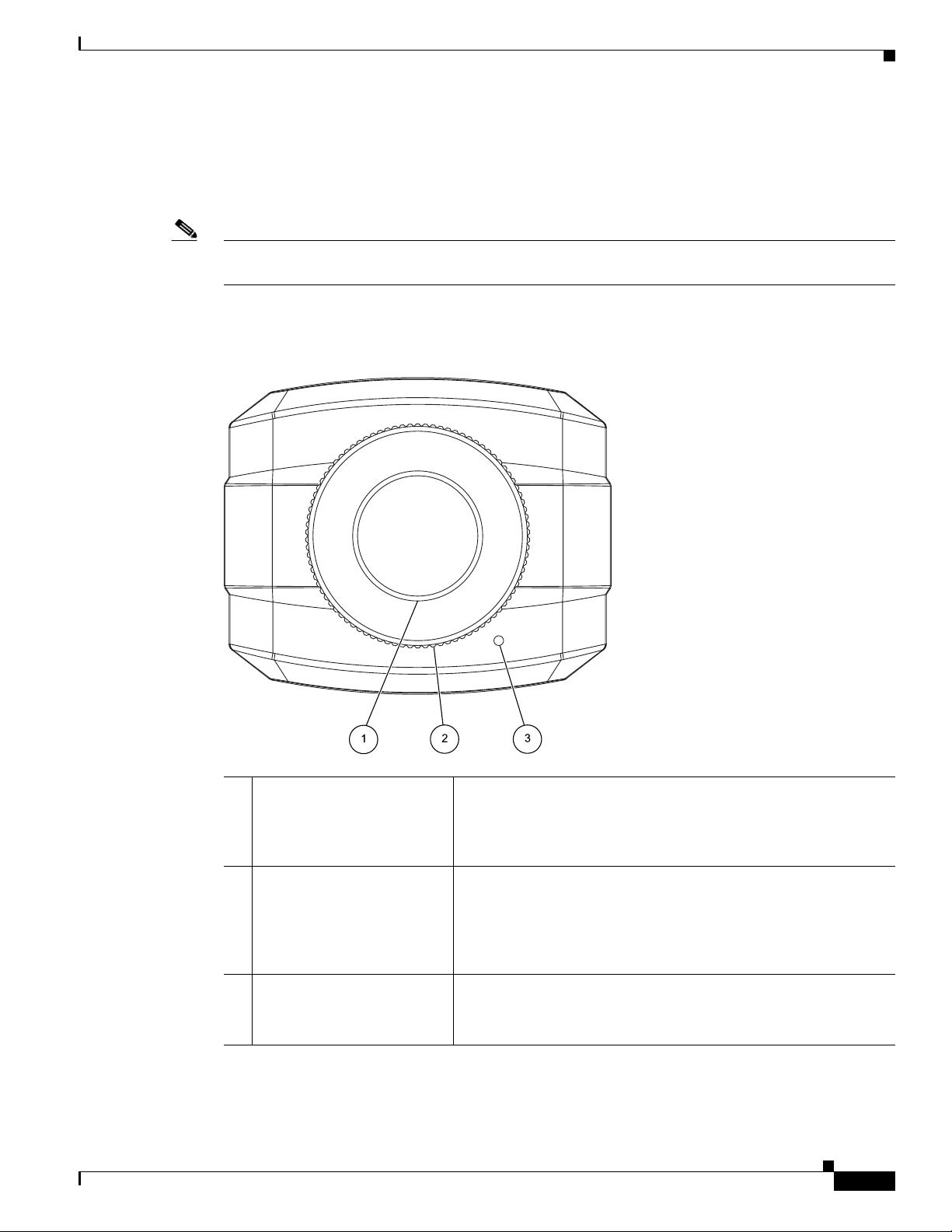
Figure 1-1 and the table that follows describe the items on the front of the IP camera.
Figure 1-1 Front of IP Camera
IP Camera Physical Details
OL-25230-02
1 Lens opening The IP camera supports a variety of C and CS mount lenses, which
attach here.
For best performance, Cisco recommends that you use a DC auto
iris lens.
2 Focus ring Allows you to adjust the back focus of the IP camera.
You must loosen the focus ring hex screw on the bottom of the IP
camera before you can rotate the focus ring. For instructions, see
the
“Adjusting Back Focus on the IP Camera” section on
page 2-10.
3 Microphone Captures audio.
There also is a connection for an optional external microphone on
the rear of the IP camera.
Cisco Video Surveillance 4300E and 4500E High-Definition IP Camera User Guide
1-3
Page 10
IP Camera Physical Details
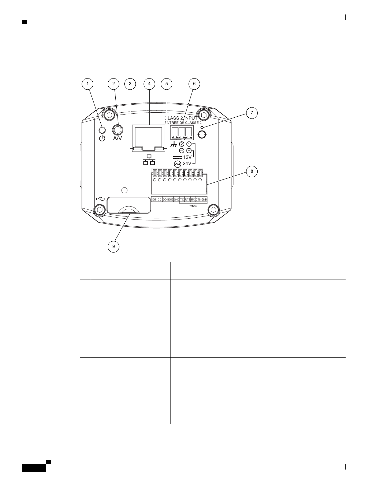
Figure 1-2 and the table that follows describe the items on the rear of the IP camera.
Figure 1-2 Rear of IP Camera
Chapter 1 Overview
1 Power LED Lights bright when the IP camera is powering up. Lights dim when
the camera is IP operating
2 Analog Audio/Video Port Allows the connection of an optional Y cable or mini cable with
BNC connector. You can connect an optional external speaker or
microphone to the Y cable, or an optional video monitor to the mini
cable with BNC connector. Both cables are included in the optional
audio/video cables accessory kit can be purchased from Cisco
(Cisco part number CIVS-IPCA-1021=).
3 PoE LED Indicates information about PoE as follows:
• Lit green—PoE connection is detected
• Off—PoE connection is not detected
4 LAN port Accepts a standard LAN cable to connect the IP camera to a
10/100BaseT router or switch.
5 Network Activity LED Indicates information about the network connections as follows:
• Lit amber—LAN connection is detected
• Off—LAN connection is not detected
• Blinking—Data is being transmitted or received via the LAN
connection
1-4
Cisco Video Surveillance 4300E and 4500E High-Definition IP Camera User Guide
OL-25230-02
Page 11
Chapter 1 Overview
IP Camera Physical Details
6 Power input Provides for the connection of an optional 12 V, 1 amp DC power
adapter or 24 VAC power adapter.
Caution Use only the Cisco specified power supply adapter.
7 Reset button Recessed button that reboots the IP camera or resets it to a default
state. You can use a pin or paper clip to depress it. It can be used
any time that the IP camera is on and can have various effects, as
described in the
8 GPIO ports General purpose input/output (GPIO) terminal block that includes
2 input ports (labeled DI1, DI2), 2 output ports (labeled DO1,
DO2), a grounding port (labeled GND), and a 5-pin RS-232 port.
9 USB port Supports up to 8 GB of USB flash storage of video data when the
camera loses network connectivity.
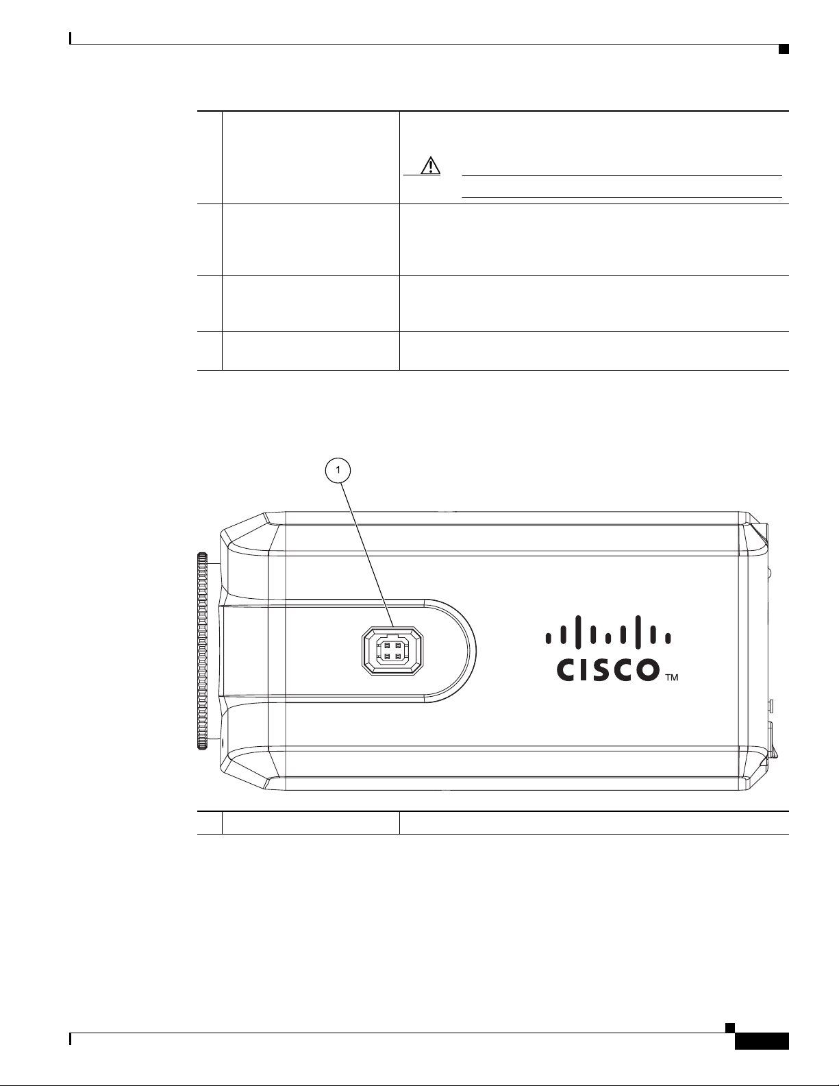
Figure 1-3 and the table that follows describe the item on the side of the IP camera.
“Resetting the IP Camera” section on page 2-11.
Figure 1-3 Side of IP Camera
1 DC auto iris lens connector Connection for cable from DC auto iris lens
OL-25230-02
Cisco Video Surveillance 4300E and 4500E High-Definition IP Camera User Guide
1-5
Page 12

DC Auto Iris Lens Connector Pinouts
DC Auto Iris Lens Connector Pinouts
Figure 1-4 describes the pinouts of the DC auto iris lens connector on the IP camera.
Figure 1-4 DC Auto Iris Lens Connector Pinouts
Pin Function
1 Damp –
2 Damp +
3 Drive +
4 Drive –
Package Contents
Chapter 1 Overview
The the Cisco Video Surveillance IP Camera package includes these items:
• Camera
• Lens opening dust cap
• USB port cover
• Terminal block for power connection
• C mount lens adaptor ring
• 0.9 mm Allen wrench for unlocking and locking the focus ring
• Quick Start Guide
1-6
Cisco Video Surveillance 4300E and 4500E High-Definition IP Camera User Guide
OL-25230-02
Page 13

CHAPTER
2
Getting Started
This chapter provides instructions for installing and performing the initial setup of the Cisco Video
Surveillance IP Camera. It also describes how to access the IP camera through a web browser so that you
can configure it or view video from it, and how to perform other important tasks.
This chapter includes these topics:
• Installing the IP Camera, page 2-1
• Performing the Initial Setup of the IP Camera, page 2-5
• Accessing the IP Camera, page 2-6
• Understanding the IP Camera User Interface, page 2-8
• Adjusting Back Focus on the IP Camera, page 2-10
• Powering the IP Camera On or Off, page 2-11
• Resetting the IP Camera, page 2-11
• Managing the Local Storage, page 2-11
Installing the IP Camera
This section describes how to install the IP camera. Before installing, review these guidelines:
• The IP camera requires a network cable and a connection to a standard 10/100BaseT router or
switch. To power the IP camera with Power over Ethernet (PoE), a switch must be 802.3af
compliant.
• If you are using the IP camera on a network connection that does not provide PoE, you must use a
Cisco 12 VDC power adapter (Cisco part number CIVS-PWRPAC-12V) or a third-party 24 VAC
power adapter.
• If you are using an external speaker, microphone, input device, output device, or pan/tilt control
device, you must configure additional settings after installing and performing the initial set up of the
IP camera before the external device can fully operate. For detailed information about these settings,
see
Chapter 3, “Configuring and Managing the IP Camera.”
• If you do not connect an external device (speaker, microphone, input, output, or pan/tilt control)
when you perform the following installation procedure, you can install any of these devices later.
• The 4300E and 4500E IP cameras can be placed in a housing that makes the back focus hex screw
inaccessible. If you are placing the camera in a housing and adjusting the back focus is required, you
must complete the procedure in the
before you install the camera using the procedure in this section.
OL-25230-02
“Adjusting Back Focus on the IP Camera” section on page 2-10
Cisco Video Surveillance 4300E and 4500E High-Definition IP Camera User Guide
2-1
Page 14

Installing the IP Camera
Chapter 2 Getting Started
Warning
Warning
Installation of the equipment must comply with local and national electrical codes.
The power supply must be placed indoors.
Note If you use the IP camera outdoors, place the camera and the power supply in a suitable NEMA
Statement 331
Statement 1074
enclosure.
Warning
Caution Inline power circuits provide current through the communication cable. Use the Cisco provided cable or
This product must be connected to a power-over-ethernet (PoE) IEEE 802.3af compliant power source
or an IEC60950 compliant limited power source.
Statement 353
a minimum 24AWG communication cable.
Note The power adapter that you use with the IP camera must provide power that is within +/–10% of the
required power.
Note The equipment is to be connected to a Listed class 2, limited power source.
To install the IP camera, follow the steps in Table 2-1. For illustrations of the connectors and ports that
the steps refer to, see the “IP Camera Physical Details” section on page 1-3.
.
Ta b l e 2-1 Installing the IP Camera
Action Explanation
Step 1
Step 2
Attach a lens to the lens opening on the IP camera. • If you are using a CS mount lens, screw the lens into
If you are using a DC auto iris lens, connect its cable to
the DC auto iris lens connector on the IP camera.
the lens opening. The IP camera accepts CS-mount
lenses with a lens protrusion of up to 5 mm.
• If you are using a C mount lens, screw the C mount
lens adapter that is supplied with the IP camera into
the lens opening, then screw the lens into the adapter.
Ensure that the lens is clean because any dirt may degrade
the quality of video images.
Note Save the lens opening dust cap and replace the dust
cap if you remove the lens.
For best performance, Cisco recommends that you use a
DC auto iris lens.
2-2
Cisco Video Surveillance 4300E and 4500E High-Definition IP Camera User Guide
OL-25230-02
Page 15

Chapter 2 Getting Started
Table 2-1 Installing the IP Camera (continued)
Action Explanation
Step 3
Optional. Use the audio Y cable to connect a speaker,
microphone, or both devices to the audio port on the rear
of the IP camera.
Step 4
Optional. Use the mini cable with BNC connector to
temporarily attach an NTSC or PAL compliant analog
video display device to the analog video out port on the
rear of the IP camera for installation purposes.
Installing the IP Camera
Each device connects to the audio Y cable through a
standard 3.5 mm mini phone jack. A speaker connects to
the red jack (speaker out) and a microphone connects to
the black jack (mic in). The Y cable that is included in the
optional audio/video cables accessory kit can be
purchased from Cisco (Cisco part number
CIVS-IPCA-1021=).
A speaker plays audio that is captured by a microphone
that is attached to the PC on which you view video from
the camera.
Place the external microphone in a location that allows it
to capture the audio that you want.
Note By default, the IP camera does not transmit or
receive audio. To enable and configure audio, see
the
“Streaming Settings Window” procedure on
page 3-3.
The analog video device displays video from the
IP
camera. The display does not include the time stamp or
text that are configured for the camera.
Connect the monitor BNC connector to the mini cable
with BNC adapter, then plug the cable into the analog
video out port. The mini cable with BNC adapter is
included in the audio/video cables accessory kit, which
you can purchase from Cisco (Cisco part number
CIVS-IPCA-1021= ).
Analog video is enabled by default to allow you to adjust
the camera field of view during installation. However, it is
not supported as a normal camera feed and is
automatically disabled when any of the following camera
settings are made:
OL-25230-02
• Audio is enabled
• Resolution is set to 1080p
• Framerate is set to 60 fps
• Mjpeg is enabled
• H.264 and mjpeg are both enabled
Note We recommend that you disable analog video after
installation. To disable analog video, see the
“Streaming Settings Window” procedure on
page 3-3.
Cisco Video Surveillance 4300E and 4500E High-Definition IP Camera User Guide
2-3
Page 16

Installing the IP Camera
Table 2-1 Installing the IP Camera (continued)
Action Explanation
Step 5
Optional. Use the GPIO ports on the rear of the IP
camera to connect external devices that trigger alarms
(connect through input ports) or respond to alarms
(connect through output ports).
Step 6
Optional. Use the RS-232 ports on the rear of the IP
camera to connect a control device (motorized housing)
that supports the Pelco D protocol.
Step 7
Connect an STP (shielded twisted pair) Category 5 or
higher network cable to the LAN port on the back of the
camera and to a 10/100/BaseT router or switch.
Step 8
If you are using the IP camera on a network connection
that does not provide PoE, connect the optional 12 VDC
or 24 VAC power adapter.
Chapter 2 Getting Started
You can connect up to two input devices and two output
devices to these ports:
DI1—Alarm input 1
DI2—Alarm input 2
DO1—Alarm output 1
DO2—Alarm output 2
GND—Ground (for use if needed)
A RS-232 cable fits into the ports in one way. Make sure
to insert it properly.
If your network provides PoE, the IP camera powers on.
Skip to
First, connect the bare wires at the end of the power
adapter to the terminal block that is provided with the IP
camera:
• With the screws on the terminal block facing down,
Step 9.
take either of these actions:
–
For a 12 VDC power adapter—Put the positive
wire into the slot at the right rear of the terminal
block, put the negative wire into the middle slot
and put the ground wire in the left slot. (On the
Cisco power adapters, the positive wire has a
white stripe and the negative wire has no stripe.)
–
For a 24 VAC power adapter—Put one wire into
the into the slot at the right rear of the terminal
block and put the other wire into the middle slot.
There is polarity, so either wire can go into either
slot.
• Use a small flat-head screwdriver to tighten the
screws on the bottom of the terminal block so that the
power adapter wires are attached securely.
Note The power adapter may include an attached
terminal block that does not fit the IP camera. If
so, remove that terminal block and replace it with
the one that is provided with the IP camera.
Next, plug the terminal block into the power input port on
back of the IP camera. The terminal block fits into the
input port in one way. Make sure that the tabs on the
terminal block face the bottom of the IP camera.
Finally, plug the power adapter into an electrical outlet.
The IP camera powers up.
2-4
Cisco Video Surveillance 4300E and 4500E High-Definition IP Camera User Guide
OL-25230-02
Page 17

Chapter 2 Getting Started
Table 2-1 Installing the IP Camera (continued)
Action Explanation
Step 9
Check the LEDs on the IP camera.
• The Ready LED lights brightly while the IP camera
starts up. After a few minutes, the Ready LED flashes
briefly then dims.
• The Network LED should be on.
Step 10
Mount the IP camera in the desired location. Connect the mounting device to the threaded mounting
hole on the bottom or top of the IP camera, depending on
your installation requirement.
After you install the IP camera, follow the instructions in the “Performing the Initial Setup of the IP
Camera” section on page 2-5 to access and configure the camera.
Performing the Initial Setup of the IP Camera
After you install IP camera as described in the “Installing the IP Camera” section on page 2-1, or after
you perform a factory reset procedure, you must access the IP camera and make initial configuration
settings. These settings include administrator and root passwords, and whether the IP camera can be
accessed through an HTTP connection in addition to the default HTTPS (HTTP secure) connection.
To make these configuration settings, you connect to the IP camera from any PC that is on the same
network as the IP camera. The PC must meet these requirements:
• Operating system—Microsoft Windows XP with Service Pack 2 or higher, or Microsoft Windows 7
Enterprise x64
Performing the Initial Setup of the IP Camera
• Browser—Internet Explorer 8.0 (32-bit only)
In addition, you must know the IP address of the IP camera. By default, when the IP camera powers on,
it attempts to obtain an IP address from a DHCP server in your network. If the camera cannot obtain an
IP address through DCHP within 90 seconds, it uses a default IP address of 192.168.0.100.
To connect to the IP camera for the first time and make initial configuration settings, perform the
following steps. You can change these configuration settings in the future as described in
“Configuring and Managing the IP Camera.”
Before you Begin
The Microsoft .NET Framework version 2.0 or later must be installed on the PC that you use to connect
to the IP camera. You can download the
Procedure
Step 1 Start Internet Explorer, enter HTTPS://ip_address in the address field, and press Enter.
.NET Framework from the Microsoft website.
Replace ip_address with the IP address that the IP camera obtained through DHCP or, if the camera was
unable to obtain this IP address, enter 192.168.0.100.
The Account window appears.
Chapter 3,
OL-25230-02
Cisco Video Surveillance 4300E and 4500E High-Definition IP Camera User Guide
2-5
Page 18

Accessing the IP Camera
Step 2 In the Set Password and Verify Password fields in the Admin column, enter a password for the IP camera
Step 3 In the Set Password and Verify Password fields in the Root column, enter a password that is used when
Step 4 In the HTTP area, click the HTTP radio button if you want to allow both HTTP and HTTPS connections
Step 5 Click Apply.
Chapter 2 Getting Started
administrator.
You must enter the same password in both fields. The password is case sensitive and must contain at least
eight characters, which can be letters, numbers, and special characters, but no spaces. Special characters
are:
! " # $ % & ' ( ) * + , - . : ; < = > ? @ [ \ ] ^ _ ` { | } ~.
accessing the IP camera through a Secure Shell (SSH) connection.
You must enter the same password in both fields. The password is case sensitive and must contain at least
eight characters, which can be letters, numbers, and special characters, but no spaces. Special characters
are:
! " # $ % & ' ( ) * + , - . : ; < = > ? @ [ \ ] ^ _ ` { | } ~.
You use the root password if you need to troubleshoot the IP camera through a SSH connection with the
assistance of the Cisco Technical Assistance Center.
to the IP camera.
The default setting is HTTPS, which allows only HTTPS (secure) connections to the IP camera.
The IP camera reboots.
Step 6 After the IP camera reboots, start Internet Explorer and, in the Address field, enter the following:
protocol://ip_address
where:
• protocol is HTTPS or HTTP. (You can use HTTP only if you enabled it in Step 4.)
• ip_address is the IP address that you used in Step 1.
Step 7 If you are prompted to install ActiveX controls, which are required to view video from the IP camera,
follow the on-screen prompts to do so.
The Home window for the IP Camera appears. For information about this window, see the
“Understanding the IP Camera User Interface” procedure on page 2-8.
Accessing the IP Camera
After you perform the initial configuration as described in the “Performing the Initial Setup of the IP
Camera” section on page 2-5, follow the steps in this section each time that you want to access the IP
camera windows to make configuration settings, view live video, or perform other activities.
You access these windows by connecting to the IP camera from any PC that is on the same network as
the IP camera and that meets these requirements:
2-6
• Operating system—Microsoft Windows XP with Service Pack 2 or higher, or Microsoft Windows 7
Enterprise x64
• Browser—Internet Explorer 8.0 (32-bit only)
You need this information to access the IP camera windows:
• IP address of the IP camera. By default, the IP camera attempts to obtain an IP address from a DHCP
server in your network. If the IP camera cannot obtain an IP address through DHCP within 90
seconds of powering up or resetting, it uses the default IP address of 192.168.0.100.
Cisco Video Surveillance 4300E and 4500E High-Definition IP Camera User Guide
OL-25230-02
Page 19

Chapter 2 Getting Started
Step 1 Start Internet Explorer and enter the following in the address field:
Accessing the IP Camera
• Port number, if other than the default value. Default port numbers for the IP camera are 443 for
HTTPS and 80 for HTTP. The IP camera administrator can configure an HTTPS port and an HTTP
port as described in the
• Your user name and password for the IP camera. The IP camera administrator configures user names
and passwords as described in the
To access the IP camera windows, perform the following these steps.
Before you Begin
The Microsoft .NET Framework version 2.0 or later must be installed on the PC that you use to connect
to the IP camera. You can download the
Procedure
protocol://ip_address:port_num ber
where:
• protocol is HTTPS for a secure connection or HTTP for a non-secure connection. You can use
HTTP only if you configure the camera to accept non-secure HTTP connections as described in the
“Performing the Initial Setup of the IP Camera” section on page 2-5.
“Account Initialization Window” section on page 3-28.
“User Settings Window” section on page 3-30.
.NET Framework from the Microsoft website.
• ip_address is the IP address of the IP camera. The default IP address is 192.168.0.100.
• port_number is the port number that is used for HTTPS or HTTP connections to the IP camera. You
do not need to enter a port number if you are connecting through the default HTTPS port 443 or the
default HTTP port 80.
For example,
• Enter the following for a secure connection if the IP address is 192.168.0.100 and the HTTPS port
number is 443:
https://192.168.0.100
• Enter the following for a secure connection if the IP address is 203.70.212.52 and the HTTPS port
number is 1024:
https://203.70.212.52:1024
• Enter the following for a non-secure connection if the IP address is 203.70.212.52 and the HTTP
port number is 80:
http://203.70.212.52
• Enter the following for a non-secure connection if the IP address is 203.70.212.52 and the HTTP
port number is 1024:
http://203.70.212.52:1024
Step 2 Enter your IP camera user name and password in the Username and Password fields, then click Login.
To log in as the IP camera administrator, enter the user name admin (which is case sensitive) and the
password that is configured for the administrator. To log in as a user, enter the user name and password
that are configured for the user.
The Home window for the IP Camera appears.
OL-25230-02
Cisco Video Surveillance 4300E and 4500E High-Definition IP Camera User Guide
2-7
Page 20

Understanding the IP Camera User Interface
Understanding the IP Camera User Interface
After you log in to the IP camera as described in the “Accessing the IP Camera” section on page 2-6, you
can access the IP camera windows and perform a variety of administrative and user procedures.
The links and activities that you can see and access in the IP camera windows depend on your IP camera
privilege level. Privilege levels are configured as described in the
page 3-30 and include the following:
• Administrator—Can access all IP camera windows, features, and functions.
• Viewer—Can access the Camera Video/Control window with limited controls, and can access the
Refresh, Logout, About, and Help links from that window.
IP Camera Window Links
The IP Camera user interface includes links that you use to access various windows and perform other
activities.
access the link.
Tabl e 2-2 describes each link and lists the IP camera privilege level that you must have to
Chapter 2 Getting Started
“User Settings Window” section on
Ta b l e 2-2 Links in the IP Camera Windows
Link Description Privilege Level
Refresh Updates the information in the window that is currently displayed. Administrator
User
Home Displays the Home window. Administrator
View Video Displays the Camera Video/Control window.
You may be prompted to install ActiveX controls when trying to
access this window for the first time. ActiveX controls are required
to view video from the IP camera. Follow the on-screen prompts to
install ActiveX controls.
Setup Provides access to the configuration menus for the IP camera. Administrator
Logout Logs you out from the IP camera. Administrator
About Displays a pop-up window with model, version, and copyright
information for the IP camera.
Help Displays reference information for the window that is currently
displayed.
Administrator
User
User
Administrator
User
Administrator
User
2-8
Cisco Video Surveillance 4300E and 4500E High-Definition IP Camera User Guide
OL-25230-02
Page 21

Chapter 2 Getting Started
IP Camera Windows
The IP camera user interface includes these main windows:
• Home window—Displays the information that is described in Table 2-3.
• Setup window—Provides access to the IP camera configuration windows. For detailed information,
see
Chapter 3, “Configuring and Managing the IP Camera.”
• Camera Video/Control window—Displays live video from the camera and lets you control a variety
of camera and display functions. For detailed information, see
Ta b l e 2-3 Home Window Information
Field Description
General Information
ID Identifier of the IP camera. To configure the ID, see the “Basic Settings
Name Name of the IP camera. To configure the name, see the “Basic Settings
Current Time Current date and time of the IP camera. To set the date and time, see the
S/N Serial number of the IP camera.
Firmware Version of the firmware that is installed on the IP camera.
Codec Version of the codec that is running on the IP camera.
Part Number Cisco manufacturing part number of the IP camera.
Top Assembly Revision Cisco assembly revision number.
Network Status
MAC Address MAC address of the IP camera.
Configuration Type Method by which the IP camera obtains its IP address. To configure this
LAN IP IP address of the LAN to which the IP camera is connected. To configure this
Subnet Mask Subnet mask of the LAN to which the IP camera is connected. To configure
Gateway Address IP address of the gateway through which the IP camera is connected. To
Primary DNS IP address of the primary DNS server, if configured for the IP camera. To
Secondary DNS IP address of the secondary DNS server, if configured for the IP camera. To
IO Port Status
Input Port 1 Current state of input port 1 on the IP camera.
Input Port 2 Current state of input port 2 on the IP camera.
Understanding the IP Camera User Interface
Chapter 4, “Viewing Live Video.”
Window” section on page 3-18.
Window” section on page 3-18.
“Time Settings Window” section on page 3-20
method, see the
IP address, see the
the subnet mask, see the
configure this IP address, see the
page 3-19.
configure a primary DNS server, see the
page 3-19.
configure a secondary DNS server, see the
on page 3-19.
“IP Addressing Window” section on page 3-19.
“IP Addressing Window” section on page 3-19.
“IP Addressing Window” section on page 3-19.
“IP Addressing Window” section on
“IP Addressing Window” section on
“IP Addressing Window” section
OL-25230-02
Cisco Video Surveillance 4300E and 4500E High-Definition IP Camera User Guide
2-9
Page 22

Adjusting Back Focus on the IP Camera
Table 2-3 Home Window Information (continued)
Field Description
Output Port 1 Current state of output port 1 on the IP camera.
Output Port 1 Current state of output port 2 on the IP camera.
Channel 1 and Channel 2
User IP camera user name of each user who is accessing the primary video stream
IP Address IP address of the client device.
Start Time Time and date that the client accessed the video stream for this session.
Elapsed Time Length of time that the client has been accessing the video stream.
Chapter 2 Getting Started
(Channel 1) or the secondary video stream (Channel 2) through a client PC
or a third-party device.
Be default, users appear in order of start time. To displays users in ascending
order of any information in any corresponding column, click the column
heading. Click a column heading again to reverse the display order.
Adjusting Back Focus on the IP Camera
To obtain the sharpest image from the camera, you may need to adjust its back focus. This adjustment is
useful if the focus control on a lens does not allow you to obtain a sharp enough image.
Note The 4300E and 4500E IP cameras can be placed in a housing that makes the back focus hex screw
inaccessible. If you are placing the camera in a housing and adjusting the back focus is required, you
must complete the procedure in this section before completing the procedure in the
Camera” section on page 2-1.
To adjust the back focus, perform the following steps while viewing video from the camera. For
information about viewing video, see
Procedure
Step 1 With a lens attached to the IP camera, use the 0.9mm Allen wrench that is supplied with the IP camera
to loosen the focus ring hex screw.
This screw is on the bottom of the camera just behind the focus ring.
Step 2 Adjust the back focus by aiming the IP camera at an object that is at least 15 feet (4.5 meters) away and
rotating the focus ring to obtain a clear image as follows:
• For a variable-focus lens, obtain a sharp picture in both wide-angle and telephoto positions.
• For a zoom lens, ensure that the object of interest remains in focus throughout the entire zoom range
of the lens.
Step 3 Use the Allen wrench to tighten the focus ring hex screw.
Chapter 4, “Viewing Live Video.”
“Installing the IP
2-10
Cisco Video Surveillance 4300E and 4500E High-Definition IP Camera User Guide
OL-25230-02
Page 23

Chapter 2 Getting Started
Powering the IP Camera On or Off
The IP camera does not include an on/off switch. You power it on or off by connecting it to or
disconnecting it from a power source. When you power off the IP camera, configuration settings are
retained.
To power on the IP camera, take either of these actions:
• Use an STP (shielded twisted pair) Category 5 or higher network cable to connect the IP camera to
a network switch that provides 802.3af compliant PoE
• Use an optional 12 VDC or 24VAC power adapter to connect the IP camera to a wall outlet
To power off the IP camera, take either of these actions:
• If the IP camera is receiving PoE, disconnect the network cable
• If the IP camera is receiving power through the power adapter, unplug the adapter from the wall or
disconnect it from the camera
Resetting the IP Camera
Powering the IP Camera On or Off
You reset the IP camera by pressing the Reset button on the rear of the device (see Figure 1-3 on
page 1-5). There are various reset types, as described in Tab le 2-4.
You also can also perform these reset operations from the Maintenance Settings window as described in
the
“Maintenance Settings Window” section on page 3-31.
Ta b l e 2-4 Resetting the IP Camera
Reset Type Procedure Remarks
Reboot. Press and immediately release
Factory reset. Press and hold the button for at
Managing the Local Storage
the Reset button.
least 15 seconds.
This action is equivalent to
powering the IP camera down
and then powering it up. Settings
that are configured for the IP
camera are retained.
Sets all IP camera options to
their default values. After you
perform this procedure, follow
the steps in the
Initial Setup of the IP Camera”
section on page 2-5.
“Performing the
OL-25230-02
The 4000E Series IP cameras have a USB port that can support an optional USB flash drive (up to 8 GB)
for local storage purposes. If local storage is available on an IP camera and the camera loses network
connectivity, video data storage switches to the local USB flash drive.
For security purposes, video data stored on the USB flash drive is encrypted. To view the encrypted
video, you must decrypt it to H.264 format. Encrypted files cannot be decrypted directly from a USB
flash drive on an IP camera; before they can be decrypted, they must either be downloaded to your PC,
or the USB flash drive must be moved from the IP camera to your PC.
Cisco Video Surveillance 4300E and 4500E High-Definition IP Camera User Guide
2-11
Page 24

Managing the Local Storage
The USB Download Decryption Utility allows you to manage the USB flash drive and to decrypt the
encrypted video data on the flash drive. The utility can be downloaded from Cisco.com and installed on
your PC. For more information see the
Utility” section on page 2-12
Note You cannot manage a USB flash drive using the camera firmware or Cisco Video Surveillance Manager
(VSM); you must use the USB Download Decryption utility.
This section includes the following local storage management topics:
• Downloading and Installing the USB Download Decryption Utility, page 2-12
• Formatting the USB Flash Drive, page 2-12
• Downloading Encrypted Video Files from the USB Flash Drive, page 2-13
• Deleting Encrypted Video Files from the USB Flash Drive, page 2-13
• Decrypting Encrypted Video Files, page 2-14
Chapter 2 Getting Started
“Downloading and Installing the USB Download Decryption
Downloading and Installing the USB Download Decryption Utility
Procedure
Step 1 Perform the following steps to obtain the USB Download Decryption Utility:
a. Go to this URL:
http://www.cisco.com/cisco/software/type.html?mdfid=282582478&flowid=7145
b. Click the Video Surveillance IP Camera Utility link.
c. Locate and choose the USB download decryption utility file, which is named
USBDownloadandDecryptionUtility2.4.0.msi, and click Download Now.
d. Log in and follow the on-screen prompts to download the file to your PC.
e. Close Internet Explorer.
Step 2 Double-click the USBDownloadandDecryptionUtility2.4.0.msi file that you downloaded in Step 1 and
follow the on-screen prompts to install the utility on your PC.
During the installation process, the installer adds the USB Download Decryption Utility icon to your
desktop.
Formatting the USB Flash Drive
2-12
Before you begin
Obtain and insert a USB flash drive into the USB port on the back of the IP camera. USB flash drives up
to 8 GB in size are supported.
Note You can purchase an 8 GB USB flash drive for the IP camera from Cisco using part number
CIVS-IPC-USB-8GB.
Cisco Video Surveillance 4300E and 4500E High-Definition IP Camera User Guide
OL-25230-02
Page 25

Chapter 2 Getting Started
Procedure
Step 1 Double-click the USB Download Decryption Utility icon to open the utility.
Step 2 Enter the IP address and root password for the IP camera and click Connect.
Step 3 Click Format USB.
Step 4 Click Ye s twice to verify that you are sure that you want to format the USB flash drive.
The USB flash drive is formatted using a FAT32 partition. If the USB flash drive was previously
formatted using a different partition type, such as NTFS, you are prompted to verify that you want to
format the USB flash drive using the FAT32 partition.
Downloading Encrypted Video Files from the USB Flash Drive
Procedure
Managing the Local Storage
Step 1 Double-click the USB Download Decryption Utility icon to open the utility.
Step 2 Enter the IP address and root password for the IP camera and click Connect.
When the utility successfully connects to the IP camera, USB flash drive capacity information and a list
of the encrypted video files are displayed.
Step 3 Do one of the following to choose the encrypted files that are to be downloaded to your PC:
• To choose all encrypted video files on the USB flash drive, click Select all.
• To choose some of the encrypted video files on the USB flash drive, click on the ones you want to
download from the file list.
Step 4 Click Save.
The selected files are copied to the specified directory, leaving the original files on the USB flash drive.
What to Do Next
To view the encrypted video files that have been downloaded, you must decrypt them. For more
information, see the
“Decrypting Encrypted Video Files” section on page 2-14
Deleting Encrypted Video Files from the USB Flash Drive
Procedure
OL-25230-02
Step 1 Double-click the USB Download Decryption Utility icon to open the utility.
Step 2 Enter the IP address and root password for the IP camera and click Connect.
When the utility successfully connects to the IP camera, USB flash drive capacity information and a list
of the encrypted video files are displayed.
Cisco Video Surveillance 4300E and 4500E High-Definition IP Camera User Guide
2-13
Page 26

Managing the Local Storage
Step 3 Do one of the following to choose the encrypted files that are to be deleted from the USB flash drive:
• To choose all encrypted video files on the USB flash drive, click Select all.
• To choose some of the encrypted video files on the USB flash drive, click on the ones you want to
delete from the file list.
Step 4 Click Delete.
The selected files are deleted from the USB flash drive.
Decrypting Encrypted Video Files
Before you begin
• Download the encrypted video files to your PC, or move the USB flash drive containing the
encrypted video files from the IP camera to your PC. For more information about downloading the
encrypted video files, see the
section on page 2-13.
Chapter 2 Getting Started
“Downloading Encrypted Video Files from the USB Flash Drive”
• Note the root password of the IP camera that created the encrypted video files.
Procedure
Step 1 Double-click the USB Download Decryption Utility icon to open the utility.
Step 2 Click the Decrypt tab.
Step 3 Do one of the following to specify the encrypted files that are to be decrypted:
• In the Input files(s) text box, enter the full path and filename for each file to be encrypted. Separate
multiple entries with a semicolon.
• Click the Browse button for the Input files(s) field, navigate to and choose the files to be encrypted,
and click Open.
Step 4 Do one of the following to specify the output directory where the decrypted files are to be saved:
• In the Output directory text box, enter the full path for the output directory.
• Click the Browse button for the Output directory field, navigate to and choose the output directory,
and click Open.
Step 5 In the password text box, enter the root password for the IP camera that created the encrypted files.
The selected files are decrypted, and for each file, the Status text box indicates whether the decryption
process failed or succeeded.
2-14
Cisco Video Surveillance 4300E and 4500E High-Definition IP Camera User Guide
OL-25230-02
Page 27

CHAPTER
3
Configuring and Managing the IP Camera
The Cisco Video Surveillance IP Camera provides configuration windows that you use to configure and
manage the IP camera. This chapter explains how to access the configuration windows, describes each
window, and provides detailed information about the options that are available in each window.
When configuring the IP camera, be aware of these guidelines:
• You must install and set up the Cisco Video Surveillance IP camera as described in Chapter 2,
“Getting Started,” before you can access the configuration menus.
• You must be an IP camera user with administrator privileges to access the configuration windows.
• For security, the configuration windows time out after 30 minutes of no activity. If a time out occurs,
you are prompted to log back in by entering your user name and password when you next press a
key or click an item. When you log back in, the home window appears.
This chapter includes these topics:
• Accessing Navigating the Configuration Windows, page 3-1
• Feature Setup Windows, page 3-2
• Network Setup Windows, page 3-18
• Administration Windows, page 3-28
• Log Windows, page 3-35
Accessing Navigating the Configuration Windows
When you are logged in to the IP camera as a user with administrator privileges, you can access the
configuration windows at any time by clicking the Setup link at the top of an IP camera window. (For
information about logging in to the IP camera, see the
When you click Setup, a window appears that includes these components:
• Navigation tree—Appears at the left of the window and provides links to each configuration window
• Configuration area—Appears to the right of the navigation tree
The navigation tree always appears. The right area varies depending on the configuration window that
you choose from the navigation tree. Use the Navigation Tree to access each configuration window. To
do so, click the link or right arrow next to the link for the group of configuration windows that you want.
The name of each associated window appears as a link. Then click the link for the desired window.
To collapse a set of links, click the down-arrow next to the top-level link.
Cisco Video Surveillance 4300E and 4500E High-Definition IP Camera User Guide
OL-25230-02
“Accessing the IP Camera” section on page 2-6).
3-1
Page 28

Feature Setup Windows
The configuration windows are organized as follows:
• Feature Setup
–
Streaming
–
Camera
–
Video Overlay
–
IO Ports
–
Pan/Tilt
–
Event
–
Patrol Sequence
–
Analytics (available for the CIVS-IPC-4500E model only)
• Network Setup
–
Basic
–
IP Addressing
–
Time
Chapter 3 Configuring and Managing the IP Camera
–
Discovery
–
SNMP
–
802.1x
–
IP Filtering
–
QoS
• Administration
–
Initialization
–
Users
–
Maintenance
–
Firmware
–
Device Processes
–
Password Complexity
• Log
–
Setup
–
Local Log
Feature Setup Windows
3-2
The Feature Setup windows let you configure a variety of IP camera features and functions. The
following sections describe the Feature Setup windows in detail:
• Streaming Settings Window, page 3-3
• Camera Settings Window, page 3-6
• Video Overlay Settings Window, page 3-8
• IO Ports Settings Window, page 3-9
Cisco Video Surveillance 4300E and 4500E High-Definition IP Camera User Guide
OL-25230-02
Page 29

Chapter 3 Configuring and Managing the IP Camera
• Pan Tilt Settings Window, page 3-10
• Event Notification Window, page 3-11
• Patrol Sequence Window, page 3-16
• Analytics Windows, page 3-18
Streaming Settings Window
The Streaming Settings window provides options for configuring audio and video streams from the IP
camera. You can configure settings for the primary and an optional secondary video stream.
Configuring a secondary stream is useful for providing a video stream that is at a lower resolution than
the primary stream to third-party devices or software.
The primary stream supports H.264 for video and G.711 A-law, G.711 u-law, and AAC for audio. The
secondary stream supports MJPEG for video and does not support audio.
When configuring video streams, be aware of the following guidelines:
• You cannot configure a secondary stream (channel 2) if you configure the resolution for the primary
stream (channel 1) to 1920 x 1080
Feature Setup Windows
• You cannot configure the resolution for the primary stream to 1920 x 1080 if a secondary stream is
enabled
• The resolution of the primary stream must be higher than the resolution of the secondary stream
• You cannot configure a maximum frame rate of 60 for the primary stream if the secondary stream is
enabled.
• Multiple secondary frame rates are now supported for MJPEG. Tab le 3-1 shows the frame rate
combinations of primary (H.264) and secondary (MJPEG) streams. If a secondary frame rate that is
not shown in this table is selected in Cisco Video Surveillance Manager, the IP camera uses the
closest available frame rate.
Ta b l e 3-1 Stream Support for Cisco Video Surveillance 4000 Series IP Camera Video
Resolution Primary (fps) Secondary (fps)
1080p 30 or lower Not supported
720p or lower 60 Not supported
30 30 15 10 5 3 1
25 25 13 5 1 — —
20 20 10 5 1 — —
15 15 8 5 3 1 —
10 10 5 1 — — —
8 8 — — — — —
6 6 — — — — —
OL-25230-02
To display the Streaming Settings window, access the configuration windows as described in the
“Performing the Initial Setup of the IP Camera” section on page 2-5, click Feature Setup, then click
Streaming.
Cisco Video Surveillance 4300E and 4500E High-Definition IP Camera User Guide
3-3
Page 30

Feature Setup Windows
Chapter 3 Configuring and Managing the IP Camera
If you change any options in this window, you must click the Save Settings button to save the changes.
If you do not click this button, changes are not retained when you exit the window. Save Settings appears
at the bottom of the window. You may need to scroll down to it.
Tabl e 3-2 describes the options in the Streaming Settings window.
Ta b l e 3-2 Streaming Settings Window Options
Option Description
Current Channel Area
Channel Choose the video stream (Channel 1 or Channel 2) to which the
configuration settings in the Streaming Settings window apply. Channel 1 is
the primary stream and Channel 2 is the secondary stream.
Enable Channel Check this check box to cause the IP camera to send audio/video data on the
selected stream.
Note Channel 2 can be enabled only if Channel 1 is set to a video
resolution lower than 1920 x 1080.
Channel Name Name of the video stream.
The name can contain up to 16 characters, which can be letters, numbers, and
special characters, but no spaces. Special characters are:
Streaming Setup Area
! % ( ) + , - : = @ _ ~
Note Each video stream uses its own set of streaming options. The settings shown in the Streaming
Setup Area apply to the currently selected stream only.
Enable SRTP Check this check box to enable Secure Real-time Transport Protocol (SRTP),
which provides encryption for the audio/video stream from the IP camera.
RTSP Port Transmission Control Protocol (TCP) port on which the IP camera receives
Real-Time Streaming Protocol (RTSP) commands. You must configure this
port if you want to allow third-party devices or software to access video
streams from the IP camera.
RTSP is a standard for connecting a client to control streaming data over the
web.
Valid values are 554 and 1024 through 65535. The default port is 554.
Video Source Port Universal Datagram Protocol (UDP) port on which the IP camera transmits
Video Real-Time Transport Protocol (RTP) data.
Valid values are even numbers 1024 through 65534. The default port is 1024.
Audio Source Port UDP port on which the IP camera transmits audio RTP data
Valid values even numbers 1024 through 65534. The default value is 1026.
Max RTP Packet Size Maximum number of bytes per data packets that are sent in each RTP
request.
Configure a lower number if you are streaming video to a cell phone that
requires smaller data packets.
Valid values are 400 through 1400. The default value is 1400.
3-4
Cisco Video Surveillance 4300E and 4500E High-Definition IP Camera User Guide
OL-25230-02
Page 31

Chapter 3 Configuring and Managing the IP Camera
Table 3-2 Streaming Settings Window Options (continued)
Option Description
Enable Multicast Check this check box to send video and audio data as a multicast stream.
Multicast Address Enter the multicast IP address on which the IP camera sends a multicast
Multicast Video Port Enter the port on which the IP camera sends a multicast video stream.
Multicast Audio Port Enter the port on which the IP camera sends a multicast audio stream.
Time to Live Enter the number of hops, which specifies the number of network devices
Feature Setup Windows
When multicast is enabled, the IP camera sends video and audio to the
multicast addresses that you designate. Multicast enables several devices to
receive the video signal from the IP camera simultaneously.
audio/video stream.
Valid values are even numbers 1024 through 65532.
Valid values are even numbers 1024 through 65532.
that an audio/video stream can pass before arriving at its destination or being
dropped.
Valid values are 1 through 255.
Video Area
Note Each video stream uses its own set of video options. The settings shown in the Video Area
apply to the currently selected stream only.
Video Standard Choose the system for video transmission: NTSC or PAL.
The setting that you make affects each channel that is enabled.
Video Codec Display only: Shows the codec for video transmission: H.264 for the primary
stream and MJPEG for the secondary stream.
Video Resolution Choose the resolution for video transmission. The resolutions in this
drop-down list depend on the video standard that you selected.
You can also change the resolution for video transmission by using the Video
Resolution drop-down list in the Camera Video/Control window, as
described in
Tabl e 4-1.
Maximum Frame Rate Choose the maximum frame rate of the video stream.
Video Quality Choose an option for the video quality of the video stream from the IP
camera:
• Constant Bit Rate—Available for the primary stream only. Specifies
that the video stream is output at or close to the constant bit rate that you
choose. The default value is 4 Mbps. A higher bit rate provides better
video quality but consumes more bandwidth.
OL-25230-02
• Fixed Quality—Specifies that video is output at a fixed quality, which
ranges from Very High to Low. The bit rate may vary to maintain this
quality. The default fixed quality is Normal. A higher fixed quality
provides better video quality but consumes more bandwidth.
You can use these options to help manage bandwidth use in your network.
For example, if the IP camera is focused on an area with little movement,
such as an emergency exit, you can configure it with a low fixed quality.
Cisco Video Surveillance 4300E and 4500E High-Definition IP Camera User Guide
3-5
Page 32

Feature Setup Windows
Chapter 3 Configuring and Managing the IP Camera
Table 3-2 Streaming Settings Window Options (continued)
Option Description
Analog Video Area
Note This option applies to the primary stream only.
Enable Analog Video
Port
Audio Area
Note These options apply to the primary stream only.
Enable Audio Check this check box if you if you want the IP camera to transmit and receive
Audio Codec Choose the codec (G.711 A-Law, G.711 u-Law, or AAC) for audio that is
Check this check box if you if you want the IP camera to enable analog video
for installation purposes. To enable analog video, the following settings are
required:
• The primary video stream resolution must be set to 720p or lower.
• The primary video stream frame rate must be set to 30 fps or lower.
• The secondary video stream must be disabled.
• Audio output must be disabled.
audio.
transmitted from the IP camera.
Audio Sampling Rate Display only. Displays the sampling rate for audio from the IP camera.
Audio Resolution Display only. Displays the resolution for audio from the IP camera.
Camera Settings Window
The Camera Settings window provides options for selecting a microphone, making certain video
adjustments, and configuring the operation of the IP camera day and night filters.
A microphone captures audio at the camera location. This audio is sent to the PC that you use to view
video from the IP camera. You can listen to the audio when viewing video in the Camera Video/Control
window.
The IP camera day and night filters allow the IP camera to optimize its video image for various lighting
conditions. When the IP camera uses its day filter, it is operating in day mode. In this mode, the camera
displays video images in color. When the IP camera uses its night filter, it is in night mode. In this mode,
the camera displays video images in black and white.
To display the Camera Settings window, access the configuration windows as described in the
“Performing the Initial Setup of the IP Camera” section on page 2-5, click Feature Setup, then click
Camera.
If you change any options in this window, you must click the Save Settings button to save the changes.
If you do not click this button, changes are not retained when you exit the window. Save Settings appears
at the bottom of the window. You may need to scroll down to it.
AAC provides highest quality audio and consumes the least bandwidth.
The default value is G.711 A-law.
3-6
Cisco Video Surveillance 4300E and 4500E High-Definition IP Camera User Guide
OL-25230-02
Page 33

Chapter 3 Configuring and Managing the IP Camera
Tabl e 3-3 describes the options in the Camera Settings window.
Ta b l e 3-3 Camera Settings Window Options
Option Description
Microphone Area
Microphone Type Choose the type of microphone that you are using.
Video Adjustments Area
Auto Iris Mode Choose whether auto iris mode is enabled or disabled:
Feature Setup Windows
• Internal Microphone—Audio is captured by the internal microphone
on the IP camera.
• External Microphone—Audio is captured by an optional external
microphone, available from third-parties. Choosing this option disables
the internal microphone.
• On—Auto iris mode is enabled. With this setting, the iris opening in the
IP camera lens adjusts automatically based on light conditions. This
setting is the default and recommended choice.
• Off - Auto iris mode is disabled. With this setting, the iris opening in the
IP camera lens remains fully open.
Sensitivity Designates how the iris opening in the IP camera lens adjusts when auto iris
mode is enabled. As sensitivity increases, the auto iris closes more to reduce
the light level and increase the depth of field in bright environments.
However, a high sensitivity may cause the image to oscillate between bright
and dim. In this situation, reduce the sensitivity to improve the image quality.
White Balance Mode Choose one the following white balance modes from the drop-down list:
• Manual—Choose this option if you want to set the white balance by
using the White Balance slider in the Camera Video/Control window as
described in
• Auto—Suitable for most conditions that do not have special lighting
• Indoor (incandescent)—Suitable for indoor conditions
• Fluorescent (white light)—Suitable for indoor conditions with
Chapter 4, “Viewing Live Video.”
fluorescent white lighting
• Fluorescent (yellow light)—Suitable for indoor conditions with
fluorescent yellow lighting
• Outdoor—Suitable for outdoor conditions.
The default setting is Auto.
Day Night Filter Area
Filter Type Choose the day/night mode for the IP camera:
OL-25230-02
• Day—IP camera always remains in day mode.
• Night—IP camera always remains in night mode.
• Auto—IP camera automatically switches between day and night mode
based on the lighting condition threshold that you specify.
Cisco Video Surveillance 4300E and 4500E High-Definition IP Camera User Guide
3-7
Page 34

Feature Setup Windows
Chapter 3 Configuring and Managing the IP Camera
Table 3-3 Camera Settings Window Options (continued)
Option Description
Day to Night Threshold If the Switch Mode option is set to Auto, choose the value that specifies the
relative light threshold at which the IP camera switches from day to night
mode. A lower value designates that the IP camera switches from day to
night mode in brighter conditions. A higher value designated that the IP
camera switches modes in darker conditions.
The default value is 10.
Night to Day Threshold If the Switch Mode option is set to Auto, choose the value that specifies the
relative light threshold at which the IP camera switches from night to day
mode. A lower value designates that the IP camera switches from night to
day mode in darker conditions. A higher value designated that the IP camera
switches modes in lighter conditions.
The default value is 15.
Enable Night Vision
Schedule
Check this check box if you want to configure the times that the camera
switches to and from night mode.
Enabling this schedule disables the Filter Type option.
Note If you configure a schedule, make sure that the time on the IP camera
Start Time Enter the time, in 24 hour format, that the camera enables its night filter.
End Time Enter the time, in 24 hour format, that the camera disables its night filter.
Video Overlay Settings Window
The Video Overlay Settings window provides options for configuring overlay information that appears
on the video image in the Camera Video/Control window.
To display the Video Overlay Settings window, access the configuration windows as described in the
“Performing the Initial Setup of the IP Camera” section on page 2-5, click Feature Setup, then click
Video Overlay.
If you change any options in this window, you must click the Save Settings button to save the change.
If you do not click this button, changes are not retained when you exit the window. Save Settings appears
at the bottom of the window. You may need to scroll down to it.
Tabl e 3-4 describes the option in the Video Overlay Settings window.
Ta b l e 3-4 Video Overlay Settings Window Options
Option Description
Text Overlay Area
Enable Time Stamp Check this check box to display the time from the internal clock of the IP
camera as an overlay on the video image from the IP camera.
Enable Text Display Check this check box to display the text that you enter in the Display Text
field as an overlay on the video image from the IP camera.
This option can be useful for identifying this IP camera in an installation
with several IP cameras.
is set correctly.
3-8
Cisco Video Surveillance 4300E and 4500E High-Definition IP Camera User Guide
OL-25230-02
Page 35

Chapter 3 Configuring and Managing the IP Camera
Table 3-4 Video Overlay Settings Window Options (continued)
Option Description
Display Text If you check the Enable Text Display check box, the text that you enter in
IO Ports Settings Window
The IO Ports Settings window lets you configure various options for the two input and two output ports
on the IP camera. A state change of an input ports triggers a camera to take configured actions. Output
ports send signals that can control external devices, such as alarms or door switches.
The IP camera can trigger an action only when the input that is received on an input port comes from a
contact that is in a normally closed condition. The camera triggers the action when the contact changes
to an open condition.
To display the IO Ports Settings window, access the configuration windows as described in the
“Performing the Initial Setup of the IP Camera” section on page 2-5, click Feature Setup, then click
IO Ports.
If you change the option in this window, you must click the Save Settings button to save the change. If
you do not click this button, changes are not retained when you exit the window. Save Settings appears
at the bottom of the window. You may need to scroll down to it.
Tabl e 3-5 describes the option in the IO Ports Settings window.
Feature Setup Windows
this field appears as an overlay on the video image from the IP camera.
The text can contain up to 26 characters, which can include letters, numbers,
spaces, and these characters:
! $ % ( ) + , - . / : = @ ^ _ ` { } ~
Ta b l e 3-5 IO Ports Settings Window Options
Option Description
Input Ports Area
Port # Display only. Indicates input port 1 and input port 2.
Current State Display only. Indicates the current state (high or low) of the corresponding
port.
Event Trigger Choose the state (Rising or Falling) that triggers designated camera actions.
When an input port changes to the configured state, the camera determines
that an event has occurred and takes the actions that you have configured.
Output Ports
Port # Display only. Indicates output port 1 and output port 2.
Current State Display only. Indicates the current state (high or low) of the corresponding
port.
Default State Choose the state (low or high) that the corresponding port is set to when the
IP camera powers on or resets.
The port changes to this state when you click Save Settings.
The default setting is High.
Event Action Display only. Indicates the current state (high or low) that the output port
changes to when an event occurs.
OL-25230-02
Cisco Video Surveillance 4300E and 4500E High-Definition IP Camera User Guide
3-9
Page 36

Feature Setup Windows
Table 3-5 IO Ports Settings Window Options (continued)
Option Description
Automatic Reset Check this check box if you want the corresponding output port to go back
Duration If you checked the Automatic Reset check box, enter the amount of time, in
Pan Tilt Settings Window
The Pan Tilt Settings window provides options for configuring pan and tilt functions for the IP camera.
These functions require that the IP camera be installed with a pan/tilt mount that supports the Pelco
protocol.
If you use a pan/tilt mount that requires RS-422 or RS-485 connections, you must connect the mount to
the IP camera through a Cisco data converter (part number CIVS-KYBD22232-B).
To display the Pan Tilt Settings window, access the configuration windows as described in the
“Performing the Initial Setup of the IP Camera” section on page 2-5, click Feature Setup, then click
Pan/Tilt.
Chapter 3 Configuring and Managing the IP Camera
to its default state after an event occurs.
milliseconds, that elapses before the port goes back to its default state after
an event changes it from the default state.
D
If you change any options in this window, you must click the Save Settings button to save the change.
If you do not click this button, changes are not retained when you exit the window. Save Settings appears
at the bottom of the window. You may need to scroll down to it.
Tabl e 3-6 describes the option in the Pan Tilt Settings window.
Ta b l e 3-6 Pan Tilt Settings Window Options
Option Description
Pan/Tilt Area
Pan and Tilt Enabled Check this check box to enable pan and tilt operation for the IP camera.
Protocol Display only. Indicates the protocol for the pan/tilt functionality.
Address Enter the logical address of the external PTZ device.
To determine this address, refer to the documentation for that device.
RS-232 Settings
Baud Rate Choose the Baud rate value that is configured on the device that controls the
pan and tilt functions of the IP camera.
The default setting is 4800 bps.
Data Bits Display only. Indicates the data bits configuration for the serial port on the
IP camera.
Parity Display only. Indicates the parity configuration for the serial port on the IP
camera.
Stop Bits Display only. Indicates the stop bits configuration for the serial port on the
IP camera.
3-10
Cisco Video Surveillance 4300E and 4500E High-Definition IP Camera User Guide
OL-25230-02
Page 37

Chapter 3 Configuring and Managing the IP Camera
Event Notification Window
The Event Notification window provides options for how the IP camera handles events. An event is any
of the following:
• A change of state from low to high or from high to low on an input port of the IP camera. For related
information about input ports, see the
• Motion that the IP camera detects. For related information about motion detection, see the “Motion
detection controls” rows in Table 4-1.
• Loss of video signal.
When an event occurs, it triggers the IP camera to take certain configured actions:
• HTTP notification—IP camera sends notification to a remote system via HTTP. This information
includes the following:
–
Device ID—ID of the IP camera
–
Device name—Name of the IP camera
–
IP address—IP address of the IP camera
–
MAC address—MAC address of the IP camera
Feature Setup Windows
“IO Ports Settings Window” section on page 3-9.
–
Channel ID—Channel identification number (1 for primary stream or 2 for secondary stream)
–
Channel name—Name that is configured for the channel
–
Date and time—Date and time that the event occurred
–
Active post Count—Sequence number of the notification for this event
–
Event type—Type of event
–
Event state—Indicates whether the event is active or inactive at the time that the event was
detected for this notification
–
Event description—Description of the event.
–
Input port ID—If the event was triggered by an input port state change, port ID of the port
–
Region index—If the event was triggered by motion detection, identification number of the
region in which the IP camera detected motion
–
Sensitivity level—If the event was triggered by motion detection, sensitivity that is configured
for the region in which motion was detected
–
Detection threshold—If the event was triggered by motion detection, threshold that is
configured for the region in which motion was detected
• Email notification—An event can cause the IP camera to send a notification e-mail message to
designated recipients. The message can include a video clip or a snapshot of the activity that
triggered the event.
This message includes the same information that is provided with HTTP notification.
• FTP notification—An event can cause the IP camera to upload a video clip or a snapshot of the
activity that triggered the event to an FTP server.
OL-25230-02
• Output port state change—Changes the state of an IP camera output port from low to high or from
high to low.
• Syslog server message—Sends a notification message to the designated Syslog server.
The Event Notification window also allows you to designate schedules. If an event takes place within a
designated schedule, the IP camera takes the actions that you configure.
Cisco Video Surveillance 4300E and 4500E High-Definition IP Camera User Guide
3-11
Page 38

Feature Setup Windows
Chapter 3 Configuring and Managing the IP Camera
To display the Event Notification window, access the configuration windows as described in the
“Performing the Initial Setup of the IP Camera” section on page 2-5, click Feature Setup, then click
Event.
If you change any options in this window, you must click the Save Settings button to save the change.
If you do not click this button, changes are not retained when you exit the window. Save Settings appears
at the bottom of the window. You may need to scroll down to it.
Tabl e 3-7 describes the option in the Event Notification window.
Ta b l e 3-7 Event Notification Window Options
Option Description
Event Triggering Area
Triggered by Check the desired check boxes to designate the events that trigger actions:
Input 1—Event is triggered when input port 1 on the IP camera changes
state from high to low.
Input 2—Event is triggered when input port 2 on the IP camera changes
state from high to low.
Motion Detection—Event is triggered when the camera detects motion, if
motion detection is configured as described the
rows in Tab le 4-1.
Video Loss—Event is triggered if the IP camera loses input to its codec
sensor module.
Actions Check the desired check boxes to designate that actions that the IP camera
takes when the corresponding trigger occurs.
“Motion detection controls”
• Email—Sends information about the event in an e-mail message to the
designated recipient. You design the recipient and configure other
e-mail options in other fields in this window.
• Output 1—Changes the state of the output 1 port on the IP camera as
defined in the Port Settings window.
• Output 2—Changes the state of the output 2 port on the IP camera as
defined in the Port Settings window.
• Syslog—Sends information about the event to a designated Syslog
server.
• HTTP—Sends information about the event as an HTTP stream to a
remote system.
• FTP—Uploads a snapshot or video clip of the event to an FTP server.
Interval Choose the time interval (in minutes) from the drop-down list to wait after
an event occurs before detecting the next event.
3-12
Cisco Video Surveillance 4300E and 4500E High-Definition IP Camera User Guide
OL-25230-02
Page 39

Chapter 3 Configuring and Managing the IP Camera
Table 3-7 Event Notification Window Options (continued)
Option Description
Event Scheduling Area
Scheduling Grid Designate the times at which an event causes the IP camera to take the
Set All button Selects all cells in the scheduling grid.
Clear All button Deselects all cells in the scheduling grid.
Undo All button Deselects cells in the scheduling grid that you selected since last saving
HTTP Notification Area
Primary HTTP Server Identify the primary server to which HTTP messages are sent by choosing
URL Base Enter a string to be used as the prefix in the HTTP URL. The HTTP URL is
Port Number Enter the port number that receives messages on the primary server to which
User Name If authentication is required on the primary server to which HTTP messages
Password If authentication is required on the primary server to which HTTP messages
HTTP Authentication If authentication is required on the primary server to which HTTP messages
Secondary HTTP Server Identify an optional secondary server to which HTTP messages are sent by
Feature Setup Windows
designed actions. If an event occurs during a time that is not designated, the
IP camera does not take any action.
Each cell in this grid represents one hour on the corresponding day, starting
at 12:00 a.m. (0:00). To designate times, click the desired cells. Selected
cells appear shaded.
To select all times, click the Set All button.
To deselect all times, click the Clear All button.
To change the scheduling settings to the last saved configuration, click
Undo.
Event Notification window settings.
IP Address or Hostname from the drop-down list and entering the IP
address or host name in the corresponding field.
sent in this format:
http://<IP address>/<URL Base>?<system-provided-name-value-pairs>
where IP address is the IP address of the destination server, URL Base is the
string that you enter, and system-provided-name-value-pairs is information
about the event.
HTTP messages are sent.
are sent, enter the user name.
are sent, enter the password.
are sent, choose the authentication method from the drop-down list.
choosing IP Address or Hostname from the drop-down list and entering the
IP address or host name in the corresponding field.
OL-25230-02
Cisco Video Surveillance 4300E and 4500E High-Definition IP Camera User Guide
3-13
Page 40

Feature Setup Windows
Chapter 3 Configuring and Managing the IP Camera
Table 3-7 Event Notification Window Options (continued)
Option Description
URL Base Enter a string to be used as the prefix in the HTTP URL for the secondary
server. The HTTP URL is sent in this format:
http://<IP address>/<URL Base>?<system-provided-name-value-pairs>
where IP address is the IP address of the destination server, URL Base is the
string that you enter, and system-provided-name-value-pairs is information
about the event.
Port Number Enter the port number that receives messages on the secondary server to
which HTTP messages are sent.
User Name If authentication is required on the secondary server to which HTTP
messages are sent, enter the user name.
Password If authentication is required on the secondary server to which HTTP
messages are sent, enter the password.
HTTP Authentication If authentication is required on the secondary server to which HTTP
messages are sent, choose the authentication method from the drop-down
list.
Email Notification Area
Primary SMTP Server Identify the primary SMTP server that is used for sending e-mail by
choosing IP Address or Hostname from the drop-down list and entering the
IP address or host name in the corresponding field.
Primary SMTP Port Enter the port number for the primary SMTP server. The default SMTP port
number is 25.
POP Server Identify the primary POP server that is used for sending e-mail by choosing
IP Address or Hostname from the drop-down list and entering the IP
address or host name in the corresponding field.
This field is dimmed if you do not choose Requires POP Before SMTP in
the Authentication field that follows.
Authentication If the primary SMTP server requires authentication to send e-mail, choose
the appropriate authentication type from the drop-down list. The
authentication type typically is the same as that for the POP3 server that you
use to receive e-mail.
Account Name If the primary SMTP server requires authentication, enter the account name
for the server.
Password If the primary SMTP server requires authentication, enter the account
password for the server.
Secondary SMTP
Server
Secondary SMTP Port Enter the port number for the secondary SMTP server. The default SMTP
Identify an optional secondary SMTP server that is used for sending e-mail
by choosing IP Address or Hostname from the drop-down list and entering
the IP address or host name in the corresponding field.
port number is 25.
3-14
Cisco Video Surveillance 4300E and 4500E High-Definition IP Camera User Guide
OL-25230-02
Page 41

Chapter 3 Configuring and Managing the IP Camera
Table 3-7 Event Notification Window Options (continued)
Option Description
POP Server Identify an optional secondary POP server that is used for sending e-mail by
Authentication If the secondary SMTP server requires authentication to send e-mail, choose
Account Name If the secondary SMTP server requires authentication, enter the account
Password If the secondary SMTP server requires authentication, enter the account
Send To Enter an e-mail address to which an e-mail message is sent when an event
Show From Address As Enter the e-mail address to be shown in the From field for the e-mail message
Subject Enter the text to be shown in the Subject field for the e-mail messages that
Attach Video Streaming
URL Address
Attach Snapshot Check this check box to include with the e-mail message a still picture from
Attach Video Clip Check this check box and enter the following values to include with the
Feature Setup Windows
choosing IP Address or Hostname from the drop-down list and entering the
IP address or host name in the corresponding field.
This field is dimmed if you do not choose Requires POP Before SMTP in
the Authentication field that follows.
the appropriate authentication type from the drop-down list. The
authentication type typically is the same as that for the POP3 server that you
use to receive e-mail.
name for the server.
password for the server.
occurs.
that is sent when an event occurs.
the IP camera sends when events occur. The subject can contain up to 118
characters, including spaces.
Check this check box to include in the e-mail message body the URL from
which the recipient can access the live video stream from the camera on
which the event was detected.
the beginning of the event. This snapshot is stored on the IP camera until the
message is sent.
This functionality is available only when the secondary video stream is
enabled.
e-mail message a video clip of the event:
OL-25230-02
• Pre-Capture Length—Enter the amount of video (in seconds) before
the event to include in the video clip.
• Post-Capture Length—Enter the amount of video (in seconds) after the
event to include in the video clip.
This video clip is stored on the IP camera until the message is sent.
FTP Notification Area
Primary FTP Server Identify the primary FTP server to which snapshots or video clips are
uploaded by choosing IP Address or Hostname from the drop-down list and
entering the IP address or host name in the corresponding field.
Primary FTP Port Enter the port number that receives messages on the primary FTP server. The
default FTP port number is 21.
User Name Enter the primary FTP server login user name.
Cisco Video Surveillance 4300E and 4500E High-Definition IP Camera User Guide
3-15
Page 42

Feature Setup Windows
Chapter 3 Configuring and Managing the IP Camera
Table 3-7 Event Notification Window Options (continued)
Option Description
Password Enter the primary FTP server login password.
Enable Passive Mode Check this check box to enable the passive mode feature of the primary FTP
server.
Secondary FTP Server Identify an optional secondary FTP server to which snapshots or video clips
are uploaded by choosing IP Address or Hostname from the drop-down list
and entering the IP address or host name in the corresponding field.
Secondary FTP Port Enter the port number that receives messages on the secondary FTP server.
The default FTP port number is 21.
User Name Enter the secondary FTP server login user name.
Password Enter the secondary FTP server login password.
Enable Passive Mode Check this check box to enable the passive mode feature of the secondary
FTP server.
Upload Snapshot Check this check box to upload a snapshot of the activity that triggered the
event.
Upload Video Clip Check this check box and enter the following values to upload a video clip
Patrol Sequence Window
The Patrol Sequence window provides options for configuring a patrol sequence for the IP camera. A
patrol sequence consists of up to eight steps, each of which causes the camera to move to a designated
preset position and remain in the position for a designated time.
When you create a patrol sequence, you define the order of the steps. When the patrol sequence runs, the
IP camera goes to the preset position that is defined by the first step, then moves through each preset
position in the configured order. It stops at the preset position that is defined by the last step.
Before you can configure a patrol sequence, you must define preset positions as described in the “Presets
controls” rows in Table 4-1. These rows also explain how to start and stop the execution of a patrol
sequence.
To display the Patrol Sequence window, access the configuration windows as described in the
“Performing the Initial Setup of the IP Camera” section on page 2-5, click Feature Setup, then click
Patrol Sequence.
If you change any options in this window, you must click the Save Settings button to save the change.
If you do not click this button, changes are not retained when you exit the window. Save Settings appears
at the bottom of the window. You may need to scroll down to it.
This functionality is available only when the secondary video stream is
enabled.
of the activity that triggered the event:
• Pre-Capture Length—Enter the amount of video (in seconds) before
the event to include in the video clip. The default pre-capture length is
0 seconds (no pre-capture video).
• Post-Capture Length—Enter the amount of video (in seconds) after the
event to include in the video clip. The default post-capture length is 5
seconds.
3-16
Cisco Video Surveillance 4300E and 4500E High-Definition IP Camera User Guide
OL-25230-02
Page 43

Chapter 3 Configuring and Managing the IP Camera
Tabl e 3-8 describes the option in the Patrol Sequence window.
Ta b l e 3-8 Patrol Sequence Window Options
Option Description
Patrol Sequence Area
Dwell Time Choose the length of time in seconds that the camera remains in each preset
Available list
Selected list
Feature Setup Windows
position when a patrol sequence runs.
Configure the order in which the IP camera executes up to 8 steps in a patrol
sequence. The Available list displays preset positions that you can use in the
patrol sequence. You define these preset positions in the Camera
Video/Control window. The Selected list displays the steps in the patrol
sequence.
When the patrol sequence executes, the IP camera goes to the first preset
position in the Selected list, then moves through each position in the list in
order. It remains in each position for the time that is defined in the Time
Delay field. It stops at the last position in the list.
To move preset positions between the Available list and the Selected list, use
the following buttons. Buttons become highlighted when they are available.
—Move the selected preset position or positions from the Available
list to the Selected list. To select a preset position, click it to
highlight it. To select more than one preset positions, Ctrl-click
each one.
—Move the selected preset position or positions from the Selected
list to the Available list. To select a preset position, click it to
highlight it. To select more than one preset positions, Ctrl-click
each one.
—Move all preset positions from the Available list to the Selected
list.
—Move all preset positions from the Selected list to the Available
list.
To configure the order of steps in the Selected list, use the following buttons.
Buttons become highlighted when they are available. To select a preset
position, click it to highlight it.
—Move the selected preset position to the top of the list.
—Move the selected preset position up one position.
—Move the selected preset position down one position.
—Move the selected preset position to the bottom of the list.
OL-25230-02
Cisco Video Surveillance 4300E and 4500E High-Definition IP Camera User Guide
3-17
Page 44

Network Setup Windows
Analytics Windows
The Analytics windows provide access to options for configuring the Cisco video analytics feature.
Note The Analytics window is available only for the CIVS-IPC-4500E model, which has the digital signal
processor (DSP) capabilities that are used for the Cisco video analytics feature. The CIVS-IPC-4300E
model does not have the DSP capabilities.
Note Even though the Cisco video analytics feature is supported by Cisco Video Surveillance Manager (VSM)
6.3.1 or later, the CIVS-IPC-4500E model is supported only by VSM 6.3.2 or later. For related
information, see the current version of Cisco Video Surveillance Manager User Guide.
To display the Analytics windows, access the configuration windows as described in the “Performing the
Initial Setup of the IP Camera” section on page 2-5, click Feature Setup, then click Analytics. A new
browser session starts and the Analytics Home window appears. This window displays video from the
IP camera and provides access to other windows that contain information and configuration options.
Chapter 3 Configuring and Managing the IP Camera
For detailed information about Cisco video analytics and the Analytics windows, see Cisco Video
Analytics User Guide.
Network Setup Windows
The Network Setup windows let you configure various network-related settings for the IP camera.
The following sections describe the Network Setup windows in detail:
• Basic Settings Window, page 3-18
• IP Addressing Window, page 3-19
• Time Settings Window, page 3-20
• Discovery Settings Window, page 3-22
• SNMP Settings Window, page 3-23
• 802.1x Settings Window, page 3-25
• IP Filter Settings Window, page 3-26
• QoS Settings Window, page 3-27
Basic Settings Window
3-18
The Basic Settings window provides options for identifying the IP camera and controlling basic
operations.
To display the Basic Settings window, access the configuration windows as described in the “Performing
the Initial Setup of the IP Camera” section on page 2-5, click Network Setup, then click Basic.
If you change any options in this window, you must click the Save Settings button to save the changes.
If you do not click this button, changes are not retained when you exit the window. Save Settings appears
at the bottom of the window. You may need to scroll down to it.
Cisco Video Surveillance 4300E and 4500E High-Definition IP Camera User Guide
OL-25230-02
Page 45

Chapter 3 Configuring and Managing the IP Camera
Tabl e 3-9 describes the options in the Basic Settings window.
Ta b l e 3-9 Basic Settings Window Options
Option Description
Basic Settings Area
ID Enter a unique identification for the IP camera, which is used to identify the
Name Enter a name for the IP camera. This name appears in the IP camera log file
Description Enter a description of the IP camera. For example, enter the IP camera
Location Enter the physical location of the IP camera, such as “North Entrance.”
Network Setup Windows
IP camera to various external applications.
The ID can contain up to 64 numbers.
for information that is associated with this IP camera.
The name can contain up to 64 characters, which can include letters,
numbers, spaces, and these characters:
recommends that you give each IP camera a unique name so that you can
identify it easily.
location, such as “North Entrance Camera 1.”
The description can contain up to 128 characters, which can include letters,
numbers, spaces, and these characters:
! $ % ( ) + , - . / = @ ^ _ ` { } ~. Cisco
! $ % ( ) + , - . / = @ ^ _ ` { } ~
Contact Enter system contact information for someone such as the system
Basic Device Operations Area
Enable Power LED Check this check box if you want the Power LED on the back of the IP
IP Addressing Window
The IP Addressing window provides options for configuring the IP address of the IP camera.
To display the IP Addressing window, access the configuration windows as described in the “Performing
the Initial Setup of the IP Camera” section on page 2-5, click Network Setup, then click IP Addressing.
If you change any options in this window, you must click the Save Settings button to save the changes.
If you do not click this button, changes are not retained when you exit the window. Save Settings appears
at the bottom of the window. You may need to scroll down to it.
The location can contain up to 64 characters, which can include letters,
numbers, spaces, and these characters:
administrator. For example, enter the e-mail address of the system
administrator.
The contact can contain up to 64 characters, which can include letters,
numbers, spaces, and these characters:
camera to light.
If you do not check this check box, this LED does not light.
! $ % ( ) + , - . / = @ ^ _ ` { } ~
! $ % ( ) + , - . / = @ ^ _ ` { } ~
OL-25230-02
Cisco Video Surveillance 4300E and 4500E High-Definition IP Camera User Guide
3-19
Page 46

Network Setup Windows
Chapter 3 Configuring and Managing the IP Camera
Tabl e 3-10 describes the options in the IP Addressing window.
Ta b l e 3-10 IP Addressing Window Options
Option Description
IP Addressing Area
IP Version Choose the IP version from the pull-down list. Currently, only IPv4 is
supported.
Configuration Type Choose the method by which the IP camera obtains its IP address:
• Dynamic—If your network includes a DHCP server for dynamic
allocation of IP addresses, choose this option if you want DHCP to
assign an IP address and subnet mask to the IP camera. Depending on
your router, the default gateway, primary DNS server, and secondary
DNS server may also be assigned. The DHCP server must be configured
to allocate static IP addresses based on MAC addresses so that the IP
camera always receives the same address.
• Static—Choose this option if you want to manually enter an IP address,
subnet mask, default gateway, and DNS server IP addresses for the
camera.
IP Address If you configured the IP camera for a static IP address, enter that IP address.
Subnet Mask If you configured the IP camera for a static IP address, enter the subnet mask
for the IP camera. Use the same value that is configured for the PCs on your
network.
Gateway Address If you configured the IP camera for a static IP address, enter the gateway for
the IP camera. Use the same value that is configured for the PCs on your
network.
Primary DNS Optional. Enter the IP address of the primary the DNS server that is used in
your network. Use the same value that is used for the PCs on your LAN.
Typically, your ISP provides this address.
This address is required if you use a host name instead of an IP address in
any configuration field in the IP camera configuration windows.
Secondary DNS Optional. Enter the IP address of a secondary (backup) DNS server to use if
the primary DNS server is unavailable. Enter the DNS server to be used if
the primary DNS server is unavailable.
This address is required if you have a secondary DNS server an you use a
host name instead of an IP address in any configuration field in the IP camera
configuration windows.
Time Settings Window
The Time Settings window provides options for setting and maintaining the time of the IP camera.
To display the Time Settings window, access the configuration windows as described in the “Performing
the Initial Setup of the IP Camera” section on page 2-5, click Network Setup, then click Time.
If you change any options in this window, you must click the Save Settings button to save the changes.
If you do not click this button, changes are not retained when you exit the window. Save Settings appears
at the bottom of the window. You may need to scroll down to it.
Cisco Video Surveillance 4300E and 4500E High-Definition IP Camera User Guide
3-20
OL-25230-02
Page 47

Chapter 3 Configuring and Managing the IP Camera
Tabl e 3-11 describes the options in the Time Settings window.
Ta b l e 3-11 Time Settings Window Options
Option Description
Set Time Mode Area
Manually Configure
Time
Use NTP Server to
Update Time
Local Time Area
Note These options do not apply if you choose the Use NTP Server to Update Time option.
Set Local Date Enter a date for the IP camera. The camera is updated with this date when
Set Local Time Enter a time for the IP camera. The camera is updated with this time when
Clone PC Time button Click this button to update the IP camera date and time with the date and time
Time Zone and Daylight Saving Area
Time Zone Choose the time zone in which the IP camera is located.
Adjust for Daylight
Saving Time
Edit Default Daylight
Saving Configuration
for Time Zone
Time Offset If you choose to overwrite the default time zone configuration, enter the
Start Date
Start Time
End Date
End Time
Network Setup Windows
Choose this option if you want to set the time for the IP camera manually.
Choose this option if you want the IP camera to obtain its time from a
network time protocol (NTP) server.
If you check this check box, the camera contacts the designated NTP server
every 64 seconds and synchronizes its internal clock with the time of that
server.
you click Save Settings.
you click Save Settings.
of the PC that you are using.
The time that appears when you view video from this IP camera reflects this
time zone.
Check this check box if you want the time of the IP camera to adjust
automatically for daylight saving time.
Check this check box if you want the daylight saving time adjustment of the
IP camera to be different than the default adjustment for the selected time
zone.
number of minutes that the time of the camera adjusts when daylight saving
time starts.
The camera automatically adjusts its time back by this number of minutes
when daylight saving time ends.
If you choose to overwrite the default time zone configuration, enter the day
and time (in 24 hour format) that daylight saving time begins. At this day and
time, the time of the IP camera adjusts by the value in the Time Offset field.
If you choose to overwrite the default time zone configuration, enter the day
and time (in 24 hour format) that daylight saving time ends. At this day and
time, the time of the IP camera adjusts to the non-daylight saving time.
OL-25230-02
Cisco Video Surveillance 4300E and 4500E High-Definition IP Camera User Guide
3-21
Page 48

Network Setup Windows
Chapter 3 Configuring and Managing the IP Camera
Table 3-11 Time Settings Window Options (continued)
Option Description
NTP Server Settings Area
Note These options do not apply if you choose the Manually Configure Time option.
Primary NTP Server If you configured the IP camera to obtain its time from an NTP server,
identify the primary NTP server by choosing IP Address or Hostname from
the drop-down list and entering the IP address or host name in the
corresponding field.
Primary NTP Server
Port
Secondary NTP Server If you configured the IP camera to obtain its time from an NTP server,
Secondary NTP Server
Port
If you configured the IP camera to obtain its time from an NTP server, enter
the primary NTP server port number.
Valid values are 123 and 1024 through 65535. The default port is 123.
identify the secondary NTP server by choosing IP Address or Hostname
from the drop-down list and entering the IP address or host name in the
corresponding field.
If you configured the IP camera to obtain its time from an NTP server, enter
the optional secondary NTP server port number.
Valid values are 123 and 1024 through 65535. The default port is 123.
Discovery Settings Window
The Discovery Settings window provides options for configuring the IP camera to work with Cisco
Discovery Protocol or Bonjour. These applications facilitate monitoring and management of your
network.
To display the Discovery window, access the configuration windows as described in the “Performing the
Initial Setup of the IP Camera” section on page 2-5, click Network Setup, then click Discovery.
If you change any options in this window, you must click the Save Settings button to save the changes.
If you do not click this button, changes are not retained when you exit the window. Save Settings appears
at the bottom of the window. You may need to scroll down to it.
Tabl e 3-12 describes the options in the Discovery Settings window.
Ta b l e 3-12 Discovery Settings Window Options
Option Description
Cisco Discovery Protocol (CDP) Area
Enable CDP Check this check box if CDP is enabled in your network and you want the
Show Neighbors button Displays a new window with information about CDP-enabled device
Bonjour Area
Enable Bonjour Check this check box if Bonjour is enabled in your network and you want the
IP
camera to broadcast CDP discovery messages.
neighbors in your network.
IP camera to broadcast Bonjour discovery messages.
3-22
Cisco Video Surveillance 4300E and 4500E High-Definition IP Camera User Guide
OL-25230-02
Page 49

Chapter 3 Configuring and Managing the IP Camera
SNMP Settings Window
The SNMP Settings window provides options for configuring Simple Network Management Protocol
(SNMP) settings for the IP camera. These settings can help you manage complex networks by sending
messages to different devices on the network.
To display the SNMP window, access the configuration windows as described in the “Performing the
Initial Setup of the IP Camera” section on page 2-5, click Network Setup, then click SNMP.
If you change any options in this window, you must click the Save Settings button to save the changes.
If you do not click this button, changes are not retained when you exit the window. Save Settings appears
at the bottom of the window. You may need to scroll down to it.
Tabl e 3-13 describes the options in the SNMP Settings window.
Ta b l e 3-13 SNMP Settings Window Options
Option Description
SNMP v2c Area
Enable SNMP v2c Check this check box to enable SNMP v2c.
Read Community String Enter the SNMP read community string, which identifies the valid read
Trap Community String Enter the SNMP trap community string.
Primary Trap Receiver Identify the primary trap receiver of the SNMP v2c manager by choosing IP
Secondary Trap
Receiver
SNMP v3 Area
Enable SNMP v3 Check this check box to enable SNMP v3.
Use Default Local
Engine ID
Network Setup Windows
community.
Address or Hostname from the drop-down list and entering the IP address
or host name in the corresponding field.
Identify an optional secondary trap receiver of the SNMP v2c manager by
choosing IP Address or Hostname from the drop-down list and entering the
IP address or host name in the corresponding field.
Click this radio button if you want to use the default local engine ID for
SNMP.
The default local engine ID is 8000000903<MAC>, where <MAC> is the
MAC address of the IP camera.
OL-25230-02
Cisco Video Surveillance 4300E and 4500E High-Definition IP Camera User Guide
3-23
Page 50

Network Setup Windows
Chapter 3 Configuring and Managing the IP Camera
Table 3-13 SNMP Settings Window Options (continued)
Option Description
Manually Configure
Local Engine ID
Primary Trap Receiver Identify the primary trap receiver of the SNMP v3 manager by choosing IP
Secondary Trap
Receiver
User # Display only. Lists the user number of each IP camera user who is configured
User Name Display only. Displays the name that is associated with the corresponding
Authentication Method Choose the authentication protocol for SNMP v3 messages that are sent on
Authentication
Password
Privacy Method Choose DES if you want to use this privacy method for SNMP v3 messages
Click this radio button if you want to enter a local engine ID manually, then
enter a unique local engine ID.
Enter this information in a standard format as defined in RFC3411. Valid
formats include (but are not limited to) the following:
• 8000000903<MAC>
where <MAC> is the MAC address of the IP camera. For example, if the
IP camera MAC address is 00:04:9F:11:22:33, enter
800000090300049F112233. This format is the default.
• 8000000901<IPv4_address_hex>
where <IPv4_address_hex> is the IPv4 address of the IP camera in
hexadecimal format. For example, if the IP camera IPv4 address is
192.168.0.100, enter 8000000901C0A80064.
• 8000000904<text>
where <text> is a string of up to 54 characters.
Address or Hostname from the drop-down list and entering the IP address
or host name in the corresponding field.
Identify an optional secondary trap receiver of the SNMP v3 manager by
choosing IP Address or Hostname from the drop-down list and entering the
IP address or host name in the corresponding field.
with the administrator privilege level.
user number
behalf of the corresponding user.
Enter a password for the authentication protocol for SNMP v3 messages that
are sent on behalf of the corresponding user.
This password can contain from 8 to 63 characters, which can be letters,
numbers, and special characters, but no spaces. Special characters are:
! $ (
) - . @ ^ _ ` { } ~
that are sent on behalf of the corresponding user.
3-24
If you do not want to use a privacy method, choose None.
Privacy Password If you choose a privacy method, enter a password for SNMP v3 messages
that are sent on behalf of the corresponding user.
This password can contain from 8 to 63 characters, which can be letters,
numbers, and special characters, but no spaces. Special characters are:
) - . @ ^ _ ` { } ~
Cisco Video Surveillance 4300E and 4500E High-Definition IP Camera User Guide
! $ (
OL-25230-02
Page 51

Chapter 3 Configuring and Managing the IP Camera
802.1x Settings Window
The 802.1x Settings window provides options for configuring 802.1x authentication for the IP camera.
These settings require that RADIUS be configured on your network to provide the client authentication.
To display the 802.1x Settings window, access the configuration windows as described in the
“Performing the Initial Setup of the IP Camera” section on page 2-5, click Network Setup, then click
802.1x (RADIUS).
If you change any options in this window, you must click the Save Settings button to save the changes.
If you do not click this button, changes are not retained when you exit the window. Save Settings appears
at the bottom of the window. You may need to scroll down to it.
Tabl e 3-14 describes the options in the 802.1x Settings window.
Ta b l e 3-14 802.1x Settings Window Options
Option Description
802.1x Settings Area
Enable 802.1x Check this check box to enable 802.1x authentication for the IP camera.
Protocol Type Choose the protocol for 802.1x authentication. Options are EAP-TLS,
EAP-TLS Configuration Options
Note These options appear if you select the protocol type EAP-TLS.
User Name Enter the user name that the IP camera uses to access the RADIUS server.
Device (Client)
Certificate
Network Setup Windows
EAP-TTLS, EAP-PEAP, and EAP-FAST.
The remaining fields in this window change depending on the protocol type
that you choose.
Path and folder where the device certificate for the IP camera is stored. You
can click Browse to find this location.
OL-25230-02
After you enter this information, click Upload to upload the certificate to the
IP camera.
Password (for Private
Key)
If the private key in the device certificate is password protected, enter the
password that is required to unlock the private key.
Root CA Certificate Path and folder where the root certificate that is required for 802.1x
authentication is stored. You can click Browse to find this location.
After you enter this information, click Upload to upload the certificate to the
IP camera.
EAP-TTLS Configuration Options
Note These options appear if you select the protocol type EAP-TTLS.
Inner Authentication Choose an inner authentication method for EAP-TTLS. Options are
MS-CHAP, MS-CHAP v2, PEAP, and EAP-MDS.
User Name Enter the user name that the IP camera uses to access the RADIUS server.
Password Enter the password that the IP camera uses to access the RADIUS server.
Anonymous ID Optional. Unsigned public identifier to be used instead of a user name for
logging in to the RADIUS server.
Validate Server
Certificate
Check this check box if you want the identity of the RADIUS server to be
validated.
Cisco Video Surveillance 4300E and 4500E High-Definition IP Camera User Guide
3-25
Page 52

Network Setup Windows
Chapter 3 Configuring and Managing the IP Camera
Table 3-14 802.1x Settings Window Options (continued)
Option Description
Root CA Certificate Path and folder where the root certificate that is required for 802.1x
authentication is stored. You can click Browse to find this location.
After you enter this information, click Upload to upload the certificate to the
IP camera.
EAP-PEAP Configuration Options
Note These options appear if you select the protocol type EAP-PEAP.
Inner EAP Protocol Choose an inner authentication method for EAP-PEAP.
User Name Enter the user name that the IP camera uses to access the RADIUS server.
Password Enter the password that the IP camera uses to access the RADIUS server.
Anonymous ID Optional. Anonymous identifier to be used instead of a user name for
logging in to the RADIUS server.
Validate Server
Certificate
Root CA Certificate Path and folder where the root certificate that is required for 802.1x
EAP-FAST Configuration Options
Check this check box if you want the identity of the RADIUS server to be
validated.
authentication is stored. You can click Browse to find this location.
After you enter this information, click Upload to upload the certificate to the
IP camera.
Note These options appear if you select the protocol type EAP-FAST.
Inner EAP Protocol Choose an inner authentication method for EAP-FAST.
User Name Enter the user name that the IP camera uses to access the RADIUS server.
Password Enter the password that the IP camera uses to access the RADIUS server.
Anonymous ID Optional. Anonymous identifier to be used instead of a user name for
Allow Automatic PAC
Provisioning
PAC f ile Path and folder where the PAC file is stored. You can click Browse to find
IP Filter Settings Window
The IP Filter Settings window provides options for controlling access to the IP camera by designating
up to 10 IP addresses or address ranges that are allowed or denied access to the IP camera.
To display the IP Filtering window, access the configuration windows as described in the “Performing
the Initial Setup of the IP Camera” section on page 2-5, click Network Setup, then click IP Filtering.
logging in to the RADIUS server.
Check this check box if you want to allow authentication servers to establish
a secure connection with the IP camera so that they can provide the IP
camera with new Protected Access Credentials (PACs).
this location.
After you enter this information, click Upload to upload the certificate to the
IP camera.
3-26
Cisco Video Surveillance 4300E and 4500E High-Definition IP Camera User Guide
OL-25230-02
Page 53

Chapter 3 Configuring and Managing the IP Camera
If you change any options in this window, you must click the Save Settings button to save the changes.
If you do not click this button, changes are not retained when you exit the window. Save Settings appears
at the bottom of the window. You may need to scroll down to it.
Tabl e 3-15 describes the options in the IP Filter Settings window.
Ta b l e 3-15 IP Filter Settings Window Options
Option Description
IP Filter Area
Enable IP Filtering Check this check box to cause the IP camera to allow or deny access to IP
Filter Entries Area
# Display only. Filter number.
Action Choose an action for the corresponding IP address or address range:
IP Address/Bit Mask Enter the IP address and bit mask to which the corresponding action applies.
Network Setup Windows
addresses as configured in the IP Filtering window.
• Deny—IP address or address range cannot access the IP camera
• Allow—IP address or address range can access the IP camera
QoS Settings Window
The QoS Settings window provides options for configuring quality of service (QoS) settings for
audio/video streams.
To display the QoS Settings window, access the configuration windows as described in the “Performing
the Initial Setup of the IP Camera” section on page 2-5, click Network Setup, then click IP Filtering.
If you change any options in this window, you must click the Save Settings button to save the changes.
If you do not click this button, changes are not retained when you exit the window. Save Settings appears
at the bottom of the window. You may need to scroll down to it.
Tabl e 3-16 describes the options in the QoS Settings window.
Ta b l e 3-16 QoS Settings Window Options
Option Description
Class of Service (CoS) Area
Enable CoS for Video
Streaming
Video Priority Value from 0 (lowest priority) through 7 (highest priority) that specifies the
Video VLAN ID Enter the ID of the video VLAN to which CoS packets are directed.
Enable CoS for Audio
Streaming
Make these entries in Classless Inter-Domain Routing (CIDR) notation.
CIDR is defined in RFC 4632.
Check this check box to enable class of service (CoS) control for video
streams.
If you enable this option, the IP camera specifies a VLAN tag that appends
to an Ethernet MAC frame for video streaming data.
CoS priority value for steaming video data.
Check this check box to enable class of service (CoS) control for audio
streams.
OL-25230-02
Cisco Video Surveillance 4300E and 4500E High-Definition IP Camera User Guide
3-27
Page 54

Administration Windows
Chapter 3 Configuring and Managing the IP Camera
Table 3-16 QoS Settings Window Options (continued)
Option Description
Audio Priority Value from 0 (lowest priority) through 7 (highest priority) that specifies the
CoS priority value for steaming audio data.
Audio VLAN ID Enter the ID of the audio VLAN to which CoS packets are directed.
Differentiated Services (DiffServ) Area
Enable DiffServ for
Video Streaming
Video DSCP Priority
Va lu e
Enable DiffServ for
Audio Streaming
Audio DSCP Priority
Va lu e
Check this check box to enable Differentiated Services (DiffServ) for video
streams.
If you enable this option, the IP camera specifies the DSCP priority value
that appends to an IP header for video streaming packets.
Value from 0 (lowest priority) through 63 (highest priority) that specifies the
DSCP priority value for steaming video data.
Check this check box to enable Differentiated Services (DiffServ) for audio
streams.
Value from 0 (lowest priority) through 63 (highest priority) that specifies the
DSCP priority value for steaming audio data.
Administration Windows
The Administrator windows lets you perform several general administrative operations, including
enabling HTTP and HTTPS access to the IP camera, configuring users, resetting or rebooting the IP
camera, and updating firmware.
The following sections describe the Administration windows in detail:
• Account Initialization Window, page 3-28
• User Settings Window, page 3-30
• Maintenance Settings Window, page 3-31
• Firmware Settings Window, page 3-33
• Device Processes Window, page 3-34
• Password Complexity Window, page 3-35
Account Initialization Window
The Account Initialization window provides options for configuring passwords for the IP camera default
administrator accounts, and for configuring which protocols can be used to access the IP camera.
The IP camera always has an HTTP/HTTPS administrator who can access the IP camera through an
HTTP or HTTPS connection. The name of this administrator is admin. The password is configurable.
If you want to access the IP camera through SSH, you must configure a password for an SSH
administrator. The name of this administrator is root. The password is configurable.
To display the Account Initialization window, access the configuration windows as described in the
“Performing the Initial Setup of the IP Camera” section on page 2-5, click Administration, then click
Initialization.
3-28
Cisco Video Surveillance 4300E and 4500E High-Definition IP Camera User Guide
OL-25230-02
Page 55

Chapter 3 Configuring and Managing the IP Camera
If you change any options in this window, you must click the Save Settings button to save the changes.
If you do not click this button, changes are not retained when you exit the window. Save Settings appears
at the bottom of the window. You may need to scroll down to it.
Tabl e 3-17 describes the options in the Account Initialization window.
Ta b l e 3-17 Account Initialization Window Options
Option Description
Administrator Accounts Area
Protocol Display only. Indicates the protocol that the corresponding administrator can
User Name Display only. Indicates the default user name for the corresponding
Password Enter a password for the corresponding administrator. The password is case
Confirm password Re-enter the password for the corresponding administrator.
Access Protocols Area
Enable HTTP Check this check box if you want to allow HTTP connections to the IP
HTTP Port Enter the HTTP port that is used to access the IP camera. Valid port numbers
Enable HTTPS Check this check box if you want to allow HTTPS connections to the IP
HTTPS Port Enter the HTTPS port that is used to access the IP camera. Valid port
Administration Windows
use to access the IP camera: HTTP/HTTPS or SSH.
administrator: admin or root
sensitive and must contain from 8 to 32 characters, which can be letters,
numbers, and special characters, but no spaces. Special characters are:
) - . @ ^ _ ` { } ~
camera.
are 80 and 1024 through 32767. The default port is 80.
If you configure the HTTP port to a value other than 80, you must specify
the port number in the URL for the IP camera when you access it through an
HTTP connection. For example, if the IP address of the IP camera is
192.168.1.100 and the HTTP port is 1024, enter this URL for the IP camera:
http://192.168.1.100:1024.
camera.
numbers are 443 and 1024 through 65535. The default port is 443.
! $ (
OL-25230-02
If you configure the HTTPS port to a value other than 443, you must specify
the port number in the URL for the IP camera when you access it through an
HTTPS connection. For example, if the IP address of the IP camera is
192.168.1.100 and the HTTPS port is 1024, enter this URL for the IP
camera: https://192.168.1.100:1024.
Enable Secure Shell
(SSH)
Check this check box if you want to allow access to the camera through a
SSH connection.
Secure Shell (SSH) Port Enter the SSH port that is used to access the IP camera. Valid port numbers
are 22 and 1024 through 65535. The default port is 22.
Cisco Video Surveillance 4300E and 4500E High-Definition IP Camera User Guide
3-29
Page 56

Administration Windows
User Settings Window
The User Settings window lets you configure the following types of IP camera users:
• Administrator—Can access all IP camera windows, features, and functions.
• Viewer—Can access only the Camera Video/Control window and all features in that window except:
–
Video image controls
–
Set Current Preset as Home button
–
Add Preset Position button
–
Deleted Selected Preset button
–
Pan/tilt speed controls
–
Motion detection controls
There is always at least one user with Administrator privileges configured. The user name of this user is
“admin.” You can configure up to four additional users and assign privilege levels to each one.
When you configure users, follow these guidelines:
• After you enter a name, password, and privilege level for a user, click Add next to the user
information to save your changes.
• To change the password for an existing user, click Change next to the user name.
Chapter 3 Configuring and Managing the IP Camera
• To remove a user, click Delete next to the user. If you delete a user who is logged into the IP camera,
the user remains logged in and can continue access the IP camera.
• To change the name of a user, you must delete the user then create a new user.
To display the User Settings window, access the configuration windows as described in the “Performing
the Initial Setup of the IP Camera” section on page 2-5, click Administration, then click Users.
Tabl e 3-18 describes the options in the User Settings window.
Ta b l e 3-18 User Settings Window Options
Option Description
User List Area
User Name Enter a unique name for the user.
The user name is case sensitive and can include up to 64 letters, numbers,
and special characters, but no spaces. Special characters are:
! % ( ) + , - =
@ _ ~
There is always one user named admin (all lower case), which cannot be
deleted.
Password Enter a password for the user.
The password is case sensitive and must contain from 8 to 32 characters,
which can be letters, numbers, and special characters, but no spaces. Special
characters are:
! $ ( ) - . @ ^ _ ` { } ~
Confirm Password Re-enter the password for the user.
3-30
Cisco Video Surveillance 4300E and 4500E High-Definition IP Camera User Guide
OL-25230-02
Page 57

Chapter 3 Configuring and Managing the IP Camera
Table 3-18 User Settings Window Options (continued)
Option Description
Privilege Level Select the desired privilege level for the user:
Change button Click this button to change the password of the corresponding user.
Add button Click this button to add the corresponding user. That user can then log in to
Delete button Click this button to remove the corresponding user. This user can no longer
Maintenance Settings Window
Administration Windows
• Administrator—Can access all IP camera windows, features, and
functions.
• Viewer—Can access the Camera Video/Control window with limited
controls, and can access the Refresh, Logout, About, and Help links
from that window.
the IP camera.
log in to the IP camera.
The Maintenance Settings window provides options for setting or restarting the IP camera, saving
configuration information from the IP camera, and uploading the configuration information to the IP
camera.
Saving and uploading configuration is useful for these activities:
• Configuring multiple IP cameras—If your network includes several IP cameras that should have
similar configurations, you can configure one IP camera, save that configuration, and upload it to
other IP cameras. Then, instead of manually configuring all options on each IP camera, you
manually configure only the options that are unique, such as the IP address, if not obtained from
DHCP.
• Backing up configuration—If you save the configuration from the IP camera, you can upload it to
the IP camera to restore the configuration if it is lost, or if you can upload it to a replacement IP
camera, if needed.
To display the Maintenance Settings window, access the configuration windows as described in the
“Performing the Initial Setup of the IP Camera” section on page 2-5, click Administration, then click
Maintenance.
If you change any options in this window, you must click the Save Settings button to save the changes.
If you do not click this button, changes are not retained when you exit the window. Save Settings appears
at the bottom of the window. You may need to scroll down to it.
OL-25230-02
Cisco Video Surveillance 4300E and 4500E High-Definition IP Camera User Guide
3-31
Page 58

Administration Windows
Chapter 3 Configuring and Managing the IP Camera
Tabl e 3-19 describes the options in the Maintenance Settings window.
Ta b l e 3-19 Maintenance Settings Window Options
Option Description
Factory Default Area
Restore button Click the Restore button to reset all IP camera settings to their factory
default values.
To confirm the restore procedure, click OK in the confirmation pop-up
window. Otherwise, click Cancel.
This action has the same effect as pressing and holding the Reset button on
the IP camera for at least 15 seconds. After you perform this procedure,
follow the steps in the
section on page 2-5.
Reset button Click the Reset button to reset all IP camera settings except the static IP
address, gateway IP address, and log in credentials (user name and
password) to their factory default values.
To confirm the restore procedure, click OK in the confirmation pop-up
window. Otherwise, click Cancel.
Reboot Area
Reboot button Click the Reboot button to reboot the software on IP camera.
“Performing the Initial Setup of the IP Camera”
To confirm the reboot procedure, click OK in the confirmation pop-up
window. Otherwise, click Cancel.
This action has the same effect as pressing and immediately releasing the
Reset button on the IP camera, or powering the IP camera down and then
powering it up.
Device Configuration Area
Export Configuration
from Camera
Click the Export button to save the current IP camera configuration
information to a binary file.
When you click this button, the File Download window appears. Use this
window to save the configuration file.
You can then load this configuration information to any same-model IP
camera in the network. This feature is useful for creating a backup of this
configuration and for configuring other IP cameras based on this
configuration.
3-32
Cisco Video Surveillance 4300E and 4500E High-Definition IP Camera User Guide
OL-25230-02
Page 59

Chapter 3 Configuring and Managing the IP Camera
Table 3-19 Maintenance Settings Window Options (continued)
Option Description
Import configuration to
camera
Administration Windows
Path and folder where a configuration file is stored. You can click Browse to
find this location. After you enter this information, click Import to load the
configuration file to the IP camera.
After you upload a configuration file to the IP camera, the IP camera restarts
automatically.
If you upload configuration from another IP camera that is active in your
network, make sure to configure this IP camera with a name, description, and
unique IP address (if not obtained through DHCP). To change these options,
see the
Addressing Window” section on page 3-19.
A configuration file that you upload includes the passwords that are
configured for the administrator and for users. If you change any passwords
after saving the configuration file, be aware that uploading the file overwrites
the new passwords with the saved ones.
“Basic Settings Window” section on page 3-18 and the “IP
Firmware Settings Window
The Firmware Settings window lets you view information about the firmware that is installed on the IP
camera and upgrade the firmware.
Before you upgrade firmware, download the firmware file to a PC that is accessible on your network and
unzip the file if it is zipped. To download firmware, go to this web page:
http://www.cisco.com/en/US/products/ps6918/Products_Sub_Category_Home.html
After you upgrade firmware, the IP camera restarts automatically. It retains all configuration
information.
To display the Firmware Settings window, access the configuration windows as described in the
“Performing the Initial Setup of the IP Camera” section on page 2-5, click Administration, then click
Firmware.
If you change any options in this window, you must click the Save Settings button to save the changes.
If you do not click this button, changes are not retained when you exit the window. Save Settings appears
at the bottom of the window. You may need to scroll down to it.
Tabl e 3-20 describes the options in the Firmware Settings window.
Ta b l e 3-20 Firmware Settings Window Options
Option Description
Device Information Area
IP Address Display only. IP address of the IP camera
MAC Address Display only. MAC address of the IP camera.
Device Name Display only. ID of the IP camera, as configured in the Basic Settings
window. For more information, see the
page 3-18.
“Basic Settings Window” section on
OL-25230-02
Cisco Video Surveillance 4300E and 4500E High-Definition IP Camera User Guide
3-33
Page 60

Administration Windows
Chapter 3 Configuring and Managing the IP Camera
Table 3-20 Firmware Settings Window Options (continued)
Option Description
Firmware Maintenance Area
Firmware Version Version of the firmware that is installed on the IP camera.
Firmware Released
Date
Details button Click this button to display a pop-up window with additional information
Firmware Upgrade To upgrade the firmware on the IP camera, begin by entering the path and
Upgrade button After entering the path and folder for the firmware file, click this button to
Release date of the current firmware.
about the firmware on the IP camera.
folder where new firmware file for the IP camera is stored. The upgrade file
may be stored on another PC. You can click Browse to find this location.
load the firmware upgrade on the IP
camera.
Do not power down the IP camera during the upgrade procedure.
Device Processes Window
The Device Processes window displays the processes that occupy TCP or UDP ports, and lets you stop
any of these processes.
Take care when stopping processes because some processes are required for the camera to operate
properly. Processes that you stop in this window can restart the next time that you log in to the IP camera.
If you delete a required process and the camera stops functioning, exit your web browser and then log
back in to the IP camera to restart the process. If the process does not restart, power the IP camera off
and then back on.
To display the Device Processes window, access the configuration windows as described in the
“Performing the Initial Setup of the IP Camera” section on page 2-5, click Administration, then click
Device Processes.
To stop any process, click the Delete button that appears to the right of the process in the window.
Tabl e 3-21 describes the options in the Product Process window. All options are for display only.
Ta b l e 3-21 Device Process Window Options
Option Description
Protocol Port (tcp or udp) that the process occupies
Local Address IP address of the device that the process is listening to
Foreign Address IP address and port number of the client device that is connected for the
State State of the process
Program Name Name of the process
process
3-34
Cisco Video Surveillance 4300E and 4500E High-Definition IP Camera User Guide
OL-25230-02
Page 61

Chapter 3 Configuring and Managing the IP Camera
Password Complexity Window
IP camera administrator and user passwords must always meet the requirements that are described in the
“User Settings Window” section on page 3-30. The Password Complexity window provides options for
configuring additional requirements for the IP camera passwords.
To display the Password Complexity window, access the configuration windows as described in the
“Performing the Initial Setup of the IP Camera” section on page 2-5, click Administration, then click
Password Complexity.
Tabl e 3-22 describes the options in the Password Complexity window.
Ta b l e 3-22 Password Complexity Window Options
Option Description
Password must contain
at least three of the
following: lower case
letters, upper case
letters, digits, and
special characters
Password cannot
include any character
that occurs three or
more times
consecutively
Password cannot be a
repeat or reverse of the
user name
Log Windows
Password must contain characters from at least 3 of these categories:
• Lower case letters (a through z)
• Upper case letters (A through Z)
• Digits (0 through 9)
• Special characters: ! " # $ % & ' ( ) * + , - . : ; < = > ? @ [ \ ] ^ _ ` { | } ~
Administrator password cannot include any character that occurs 3 or more
times in a row.
Password cannot be the same as the user name either forward of reversed
Log Windows
The Log windows let you set up and view the IP camera log file, which captures information about the
IP camera and its activities.
The IP camera stores the log file in its internal SDRAM. If the SDRAM becomes full, the IP camera
begins to overwrite existing information. To avoid losing log information, you can configure the IP
camera to send log information to a Syslog server.
Caution Because the logs are stored in the internal camera SDRAM, all existing logs in the camera will be lost
after a camera reboot, power-up, or power-down.
The following sections describe the Log windows in detail:
• Log Setup Settings Window, page 3-36
• Local Log Window, page 3-38
OL-25230-02
Cisco Video Surveillance 4300E and 4500E High-Definition IP Camera User Guide
3-35
Page 62

Log Windows
Log Setup Settings Window
The Log Setup Settings window provides options for configuring the log file and an optional syslog
server on which to store log files.
To display the Log Setup Settings window, access the configuration windows as described in the
“Performing the Initial Setup of the IP Camera” section on page 2-5, click Log, then click Setup.
If you change any options in this window, you must click the Save Settings button to save the changes.
If you do not click this button, changes are not retained when you exit the window. Save Settings appears
at the bottom of the window. You may need to scroll down to it.
Tabl e 3-23 describes the options in the Log Setup Settings window.
Ta b l e 3-23 Log Setup Settings Window Options
Option Description
Local Log Settings Area
Minimum Log Severity Choose the minimum severity of messages that the appear in the log file. The
Chapter 3 Configuring and Managing the IP Camera
system logs all messages of this severity and higher. Message severities,
from highest to lowest, are:
• Emergency—The system is unusable.
• Alert—A situation occurred that requires immediate action.
• Critical—A situation occurred that requires action soon.
• Error—An error occurred, but it does not necessarily affects the ability
of the system to function.
• War nin g—A undesirable condition occurred.
• Notice—Notification about a system condition that is not necessarily an
error condition.
• Informational—Information about a system activity.
• Debug—Information about a system activity with detailed technical
information. Includes messages of every other severity.
The default severity is Informational.
Maximum Log Entries Maximum number of entries that the log file maintains. When the log file
reaches this limit, it begins overwriting entries, starting with the oldest one.
The default value is 100.
Syslog Settings Area
Enable Syslog Check this check box to send the log information to a designated Syslog
server. The selected information also is maintained on the IP camera until it
is overwritten.
This option is useful for consolidating logs in deployments with several
IP
cameras and for retaining logs.
Primary Syslog Server Identify the primary Syslog server by choosing IP Address or Hostname
from the drop-down list and entering the IP address or host name in the
corresponding field.
Primary Syslog Server
Port
Enter the primary Syslog server port number that receives the logs.
Valid values are 514 and 1024 through 65535. The default Syslog port is 514.
3-36
Cisco Video Surveillance 4300E and 4500E High-Definition IP Camera User Guide
OL-25230-02
Page 63

Chapter 3 Configuring and Managing the IP Camera
Table 3-23 Log Setup Settings Window Options (continued)
Option Description
Facility Enter the system facility that receives logs on the Syslog server.
Minimum Log Severity Choose the minimum severity of messages that are sent to the Syslog server.
Secondary Syslog
Server
Secondary Syslog
Server Port
Facility Enter the system facility that receives logs on the Syslog server.
Minimum Log Severity Choose the minimum severity of messages that are sent to the secondary
Log Windows
The system sends all messages of this severity and higher. Message
severities, from highest to lowest, are:
• Emergency—The system is unusable.
• Alert—A situation occurred that requires immediate action.
• Critical—A situation occurred that requires action soon.
• Error—An error occurred, but it does not necessarily affects the ability
of the system to function.
• War nin g—A undesirable condition occurred.
• Notice—Notification about a system condition that is not an error
condition.
• Informational—Information about a system activity.
• Debug—Information about a system activity with detailed technical
information. Includes messages of every other severity.
The default severity is Informational.
Identify an optional secondary Syslog server by choosing IP Address or
Hostname from the drop-down list and entering the IP address or host name
in the corresponding field.
Enter the port number that receives the logs on the secondary Syslog server.
Valid values are 514 and 1024 through 65535. The default Syslog port is 514.
Syslog server. The system sends all messages of this severity and higher.
Message severities, from highest to lowest, are:
• Emergency—The system is unusable.
OL-25230-02
• Alert—A situation occurred that requires immediate action.
• Critical—A situation occurred that requires action soon.
• Error—An error occurred, but it does not necessarily affect the ability
of the system to function.
• War nin g—An undesirable condition occurred.
• Notice—Notification about a system condition that is not an error
condition.
• Informational—Information about a system activity.
• Debug—Information about a system activity with detailed technical
information. Includes messages of every other severity.
Cisco Video Surveillance 4300E and 4500E High-Definition IP Camera User Guide
3-37
Page 64

Log Windows
Local Log Window
The Local Log window lets you view the log file that is stored on the IP camera.
To display the Local Log window, access the configuration windows as described in the “Performing the
Initial Setup of the IP Camera” section on page 2-5, click Log, then click Local Log.
Tabl e 3-24 describes the options in the Local Log window.
Ta b l e 3-24 Local Log Window Options
Option Description
Log List Area
Rows per page Choose the number of log entry rows to display per page and click the Go
Filter Choose the type of log message to include in the display.
Since Choose the time period for which you want to view log messages.
Go button Update the log display based on the values in the Filter and Since fields.
Severity An icon in this column indicates the severity of the corresponding log
Chapter 3 Configuring and Managing the IP Camera
button to the right of this option to update the display.
To include messages of every severity, choose All.
message:
—Emergency message
—Alert message
—Critical message
—Error message
—Warning message
—Notice message
—Informational message
—Debug message
To display log messages in order of severity with the least severity first, click
the Severity column heading. Click the heading again to reverse the display
order.
Date/Time Date and time that the logged activity occurred.
By default, log messages appear in the order that the activity occurred with
the oldest message first. To reverse this display order, click the Date/Time
column heading.
Description Message that describes the logged activity. For detailed information about
log messages, see
Table 3-25 on page 3-39.
3-38
Cisco Video Surveillance 4300E and 4500E High-Definition IP Camera User Guide
OL-25230-02
Page 65

Chapter 3 Configuring and Managing the IP Camera
Table 3-24 Local Log Window Options (continued)
Option Description
Page controls Let you move through the log file entries:
Tabl e 3-25 describes the messages that can appear in the IP camera log file. When you view the log file,
each message includes the date and time that it was logged. In this table:
• Messages appear in alphabetical order
• Angle brackets (<>) indicate items that are replaced by appropriate information when the message
appears. Italic text describes these items.
• Severity indicates the severity of the message:
Log Windows
Page field—Enter a page number and press Enter.
—Go to first page
—Go to previous page
—Go to next page
—Go to last page
–
0—Emergency (the system is unusable)
–
1—Alert (a situation occurred that requires immediate action)
–
2—Critical (a situation occurred that requires action soon)
–
3—Error (an error occurred, but it does not necessarily affect the ability of the system to
function)
–
4—Warning (an undesirable condition occurred)
–
5—Notice (notification about a system condition that is not an error condition)
–
6—Informational (information about a system activity)
–
7—Debug (information about a system activity with detailed technical information)
Ta b l e 3-25 Log Messages
Message Name Description that Appears in Log File Explanation Severity
AUTHENTICATION_FAILED Access authentication to <web server,
streaming server, or SSH server> by
An attempt to log in or authenticate to
the IP camera failed.
3
user <user> <IP address or
hostname> failed.
AUTHENTICATION_FAILED Access authentication to <server type>
server <server IP address or
hostname> failed.
AUTHORIZATION_FAILED Unauthorized address <IP address or
hostname> attempted to access camera.
The IP camera was unable to access an
SNTP, Syslog, DNS, SMTP, HTTP, or
802.1x server.
An attempt was made to access the IP
camera by using invalid user
4
3
credentials for from an IP address that
has been configured for no access.
CODEC_LOST Connection to Codec/Sensor module
was lost. Internal module is either down
The IP camera codec/sensor module is
not responding.
4
or not responding.
OL-25230-02
Cisco Video Surveillance 4300E and 4500E High-Definition IP Camera User Guide
3-39
Page 66

Chapter 3 Configuring and Managing the IP Camera
Log Windows
Table 3-25 Log Messages
Message Name Description that Appears in Log File Explanation Severity
CONFIG_SAVE_FAILED Saving configuration to user <user>
<IP address or hostname> failed.
CONFIG_SAVED Configuration saved by user <user>
<IP address or hostname>.
CONFIG_UPLOAD_FAILED Uploading configuration failed from
user <user> <IP address or hostname>.
CONFIG_UPLOADED Configuration uploaded from user
<user> <IP address or hostname>.
DEFAULTS_FAILED Restoring factory defaults failed for
user <user> <IP address or hostname>.
DEFAULTS_RESTORED Factory defaults restored successfully
by user <user> <IP address or
hostname>.
DEVICE_REBOOT_AUTO Device rebooted. The IP camera rebooted automatically. 5
DEVICE_REBOOT_MANUAL Device was rebooted manually by user
<user> <IP address or hostname>.
DHCP_LEASE DHCP lease renewal was successful. The IP camera renewed its DHCP
DSP_ENCODING_HALTED The Codec/Sensor module’s DSP
encoding was halted. Either the analog
image signal from the sensor has been
lost, or an internal encoding error has
occurred.
EMAIL_TRIGGERED Event triggered: email sent to <e-mail
address>.
ETH_BER Bit Error Rate (BER) exceeded
specified threshold of <threshold>.
ETH_SIGNAL_DEGRADE Ethernet signal degrading. The IP camera detected a degrading
FRAMES_DROPPED Output frame rate does not match the
camera’s configured frame rate.
FW_UPGRADE_FAILED Upgrading firmware failed from user
<user> <IP address or hostname>.
FW_UPGRADED Firmware upgraded successfully from
user <user> <IP address or hostname>.
HTTP_TRIGGERED Event triggered: notification sent to
HTTP server <IP
address or
hostname>.
INPUT_ONE_CHANGED Input port one changed to <high/low>. Input port 1 on the IP camera changed
INPUT_ONE_RESET Input port one reset to <high/low>. Input port 1 on the IP camera reset to
A user attempt to save the IP camera
configuration failed.
The IP camera configuration was saved
by a user.
A user attempt to import the IP camera
configuration failed.
The IP camera configuration was
imported by a user.
An attempt to reset the IP camera to its
factory default configuration failed.
The IP camera was reset to its factory
default configuration.
The IP camera was rebooted by a user. 5
lease.
The DSP of the IP camera codec/sensor
module DSP stopped encoding. The
analog image signal from the sensor
may be lost or an internal encoding
error may have occurred.
An event occurred and e-mail
notification of the event was sent.
The bit error rate (BER) exceeded the
specified threshold.
Ethernet signal.
The IP camera is sending video at a
frame rate that does not match the
configured frame rate.
An attempt to upgrade the IP camera
firmware failed.
The IP camera firmware was updated. 5
An event occurred and HTTP
notification of the event was sent.
state.
its default state.
3
5
3
5
3
5
6
2
5
4
4
3
0
5
5
5
3-40
Cisco Video Surveillance 4300E and 4500E High-Definition IP Camera User Guide
OL-25230-02
Page 67

Chapter 3 Configuring and Managing the IP Camera
Log Windows
Table 3-25 Log Messages
Message Name Description that Appears in Log File Explanation Severity
INPUT_TWO_CHANGED Input port two changed to <high/low>. Input port 1 on the IP camera changed
state.
INPUT_TWO_RESET Input port two reset to <high/low>. Input port 1 on the IP camera reset to
its default state.
IP_CONFLICT IP Address conflict for <IP address>. IP camera experienced an IP address
conflict.
IR_FILTER_DAY_AUTO IR filter changed to day automatically. The IP camera enabled its day filter
automatically.
IR_FILTER_DAY_MANUAL IR filter manually changed to day by
user <user> <IP address or hostname>.
IR_FILTER_NIGHT_AUTO IR filter changed to night
automatically.
IR_FILTER_NIGHT_MANUAL IR filter changed to night by user
<user> <IP address or hostname>.
LOG_IN User <user> <IP address or hostname>
The IP camera day filter was enabled
by a user.
The IP camera enabled its night filter
automatically.
The IP camera night filter was enabled
by a user.
A user logged in to the IP camera. 5
logged in to <web server or SSH
server>.
LOG_OUT User <user> <IP address or hostname>
A user logged out of the IP camera. 5
logged out of <web server or SSH
server>.
MOTION_DETECTED Motion detected in region <region
index>.
MOTION_STOPPED Motion in region <region index>
stopped.
The IP camera detected motion in its
video field.
The IP camera stopped detecting
motion in its video field.
OUTPUT_ONE_RESET Output port one reset to <high/low>. Output port 1 on the IP camera reset to
its default state.
OUTPUT_ONE_TRIGGERED Output port one triggered to
<high/low>.
Output port 1 on the IP camera
changed state.
OUTPUT_TWO_RESET Output port two reset to <high/low>. Output port 2 on the IP camera reset to
its default state.
OUTPUT_TWO_TRIGGERED Output port two triggered to
<high/low>.
PAN Pan <left/right> by user <user>
<IP
address or hostname>.
PATRO L_ START Patrol started by user <user> <IP
address or hostname>.
PATRO L_ STOP Patrol stopped by user <user> <IP
address or hostname>.
Output port 2 on the IP camera
changed state.
The IP camera was panned by a user. 6
A patrol sequence was started by a
user.
A patrol sequence was stopped by a
user.
POWER_SUPPLY_FAILURE DC power supply failure. The DC power for the IP camera failed. 2
PTZ_LOST Connection to PTZ device was lost.
Device is either down or not
The pan/tilt device that the IP camera
is connected to is not responding.
responding.
5
5
4
6
6
6
6
5
5
5
5
5
5
6
6
4
OL-25230-02
Cisco Video Surveillance 4300E and 4500E High-Definition IP Camera User Guide
3-41
Page 68

Chapter 3 Configuring and Managing the IP Camera
Log Windows
Table 3-25 Log Messages
Message Name Description that Appears in Log File Explanation Severity
SERVER_CONTACTED Communication established with
<server type> server <server or
IP
address>.
SERVER_LOST Communication lost with <server
type> server <server or IP address>.
SERVER_UNREACHABLE Failed to contact <server type> server
<server or IP
address>.
START_STREAM Channel <channel ID> started
streaming to user <user> <IP address
or hostname>.
STOP_STREAM Channel <channel ID> stopped
streaming to user <user> <IP address
or hostname>.
TEMP_THRESHOLD_T1 Current temperature, <temperature>,
<exceeds/is below> <high
temperature/
low_temperature> threshold.
TEMP_THRESHOLD_T2 Current temperature, <temperature>,
<exceeds/is below> <high
temperature/
low_temperature> threshold.
TEMP_THRESHOLD_T3 Current temperature, <temperature>,
<exceeds/is below> <high
temperature/
low_temperature> threshold.
TILT Tilt <up/down> by user <user>
<IP
address or hostname>.
TIME_DST_SWITCH Time switched to Daylight Savings
time with an offset of <offset> minutes.
TIME_REG_SWITCH Time switched from Daylight Savings
time with an offset of <offset> minutes.
UNEXPECTED_EXCEPTION Unexpected exception occurred. Pan
<left/right> failed by user <user> <IP
address or hostname>.
UNEXPECTED_EXCEPTION Unexpected exception occurred. Tilt
<up/down> failed by user <user>
<IP
address or hostname>.
UNEXPECTED_EXCEPTION Unexpected exception occurred. Patrol
failed by user <user> <IP address or
hostname>.
UNEXPECTED_EXCEPTION Unexpected exception occurred. Could
not <read/write> <to/from> repository
by user <user> <IP address or
hostname>.
The IP camera established
communication with an SNTP, DHCP,
Syslog, DNS, SMTP, HTTP, or 802.1x
server.
The IP camera lost communication
with an SNTP, DHCP, Syslog, DNS,
SMTP, HTTP, or 802.1x server.
The IP camera was unable to contact an
SNTP, DHCP, Syslog, DNS, SMTP,
HTTP, or 802.1x server or a gateway.
The IP camera began streaming video
to a user device.
The IP camera stopped streaming
video to a user device.
The internal temperature of the IP
camera is lower than 59°F (15°C) or
higher than 149°F (65°C).
The internal temperature of the IP
camera is lower than 32°F (0°C) or
higher than 176°F (80°C).
The internal temperature of the IP
camera is lower than 5°F (–15°C) or
higher than 194°F (90°C).
The IP camera was tilted by a user. 6
The IP camera internal clock switched
to daylight saving time.
The IP camera internal clock switched
to standard time.
An attempt by a user to pan the IP
camera failed.
An attempt by a user to tilt the IP
camera failed.
An attempt by a user to start a patrol
sequence failed.
IP camera could not read or write
information to its internal repository.
6
4
4
6
6
2
4
5
6
6
1
1
1
2
3-42
Cisco Video Surveillance 4300E and 4500E High-Definition IP Camera User Guide
OL-25230-02
Page 69

CHAPTER
4
Viewing Live Video
After you install and set up the Cisco Video Surveillance IP Camera as described in Chapter 2, “Getting
Started,” users can connect to the IP camera through Internet Explorer and access the Camera
Video/Control window to view live video from the IP camera.
The Camera Video/Control window also provides for controlling the video display, configuring preset
positions, and controlling certain IP camera functions. Available controls depend on the privilege level
of the user.
To view live video, log in to the IP camera as described in the “Accessing the IP Camera” section on
page 2-6, then click View Video in the IP camera Main window menu bar. The Camera Video/Control
window appears. This window displays live video from the camera and lets you control a variety of
camera and display functions.
The controls that you see in the Camera Video/Control window depend on your IP camera privilege level
and the configurations settings for the IP camera. Users with the Administrator privilege can access all
controls. Users with the Viewer privilege do not have access to the following controls:
• Video image controls
• Set Current Preset as Home button
OL-25230-02
• Add Preset Position button
• Deleted Selected Preset button
• Pan/tilt speed controls
• Motion detection controls
Tabl e 4-1 describes the controls in the Camera Video/Control window.
Ta b l e 4-1 Camera Video/Control Window Controls
Control Description
Video controls
Video Codec
drop-down list
Choose the codec for video transmission (H.264 or MJPEG).
You can choose H.264 only if the primary video stream (channel 1) is enabled.
You can choose MJPEG only if the secondary video stream (channel 2) is
enabled.
For information about enabling and disabling video streams, see the
“Streaming Settings Window” section on page 3-3.
Cisco Video Surveillance 4300E and 4500E High-Definition IP Camera User Guide
4-1
Page 70

Table 4-1 Camera Video/Control Window Controls (continued)
Control Description
Video Resolution
drop-down list
Right Arrow toggle
button
Left Arrow toggle
button
Choose the resolution for video transmission. The resolutions in this
drop-down list depend on the video standard that you selected.
The default value for H.264 is 1920 x 1080. The default value for MJPEG is
704 x 480.
You cannot configure a secondary stream if you configure this resolution for
1920 x 1080.
Note You can also change the resolution for video transmission by changing
the value in the Video Resolution Type field, as described in the
“Streaming Settings Window” section on page 3-3.
Click the Right Arrow to display the video image controls. The button changes
to the Left Arrow button.
Click the Left Arrow button to hide the video image controls. The button
changes to the Right Arrow button.
Chapter 4 Viewing Live Video
Video image controls
Note These controls appear when you click the Right Arrow in the Video Control area.
White Balance slider To control the white balance of the video image, drag the slider, or enter a
value from 1 through 100 and press the Enter key. A higher value increases
white balance and a lower value decreases white balance.
If the White Balance Mode option is not set to Manual as described in the
“Camera Settings Window” section on page 3-6, changing the white balance
value sets that option to Manual automatically.
The default value is 50.
Brightness slider To control the brightness of the video image, drag the slider, or enter a value
from 1 through 100 and press the Enter key. A higher value increases the
brightness and a lower value decreases the brightness. For example, if the IP
camera is facing a bright light and the video appears too dark, you can increase
the brightness.
The default value is 50.
Contrast slider To control contrast of the video image, drag the slider, or enter a value from 1
through 100 and press the Enter key. A higher value increases the contrast and
a lower value decreases the contrast.
The default value is 50.
Sharpness slider To control the sharpness of the video from the IP camera, drag the slider, or
enter a value from 1 through 100 and press the Enter key. A higher value
increases the sharpness and a lower value decreases the sharpness.
The default value is 50.
4-2
Cisco Video Surveillance 4300E and 4500E High-Definition IP Camera User Guide
OL-25230-02
Page 71
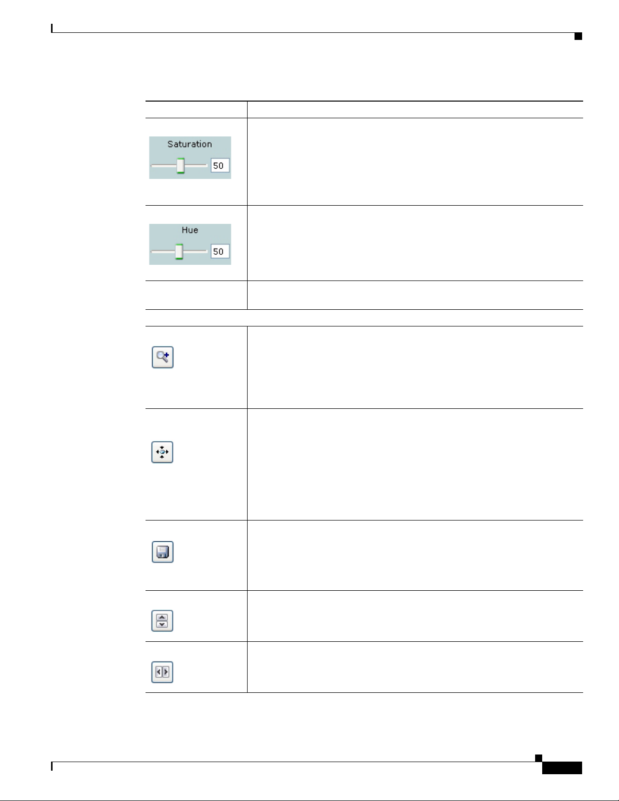
Chapter 4 Viewing Live Video
Table 4-1 Camera Video/Control Window Controls (continued)
Control Description
Saturation slider To control the saturation of the video from the IP camera, drag the slider, or
Hue slider To control the hue of the video from the IP camera, drag the slider, or enter a
Restore button Resets white balance, brightness, contrast, sharpness, saturation, and hue to
Image tools
Hotspot Zoom button Click this latch button to enables the digital zoom feature, which provides
Hotspot Pan/Tilt
button
enter a value from 1 through 100 and press the Enter key. A higher value
increases the saturation and a lower value decreases the saturation.
High saturation provides a vivid, intense color for a video image. With less
saturation, the video image appears more muted and gray.
The default value is 50.
value from 1 through 100 and press the Enter key. A higher value increases
the hue and a lower value decreases the hue.
Hue is the relative balance of primary colors.
The default value is 50.
their default values.
five-step digital zooming in for the normal (not full screen) video display.
Click this button again to disable the digital zoom feature.
To perform a digital zoom, engage the Hotspot Zoom button and click the
video display. The first five clicks zoom the display. The sixth click returns to
unzoomed display.
Click this latch button to enable the hotspot pan/tilt feature, which lets you pan
and tilt the IP camera toward a point that you click in the video display.
To perform a hotspot pan/tilt action, engage the Hotspot Pan/Tilt button, then
click the video image at the location toward which you want the IP camera to
pan and tilt.
OL-25230-02
This feature require that the IP camera be installed with a pan/tilt mount that
supports the Pelco D protocol and that pan and tilt functions are enabled. For
more information, see the
“Pan Tilt Settings Window” section on page 3-10.
Save Snapshot button Captures and saves a the current video image as a .gif file or a .jpg file in the
location of your choice and with the file name of your choice.
When you click this button, the Snapshot window appears. Click Save and
follow the on-screen prompts to save the image with the name and in the
location that you want.
Flip button Rotates the video image by 180 degrees.
Mirror button Reverses the video image.
Cisco Video Surveillance 4300E and 4500E High-Definition IP Camera User Guide
4-3
Page 72
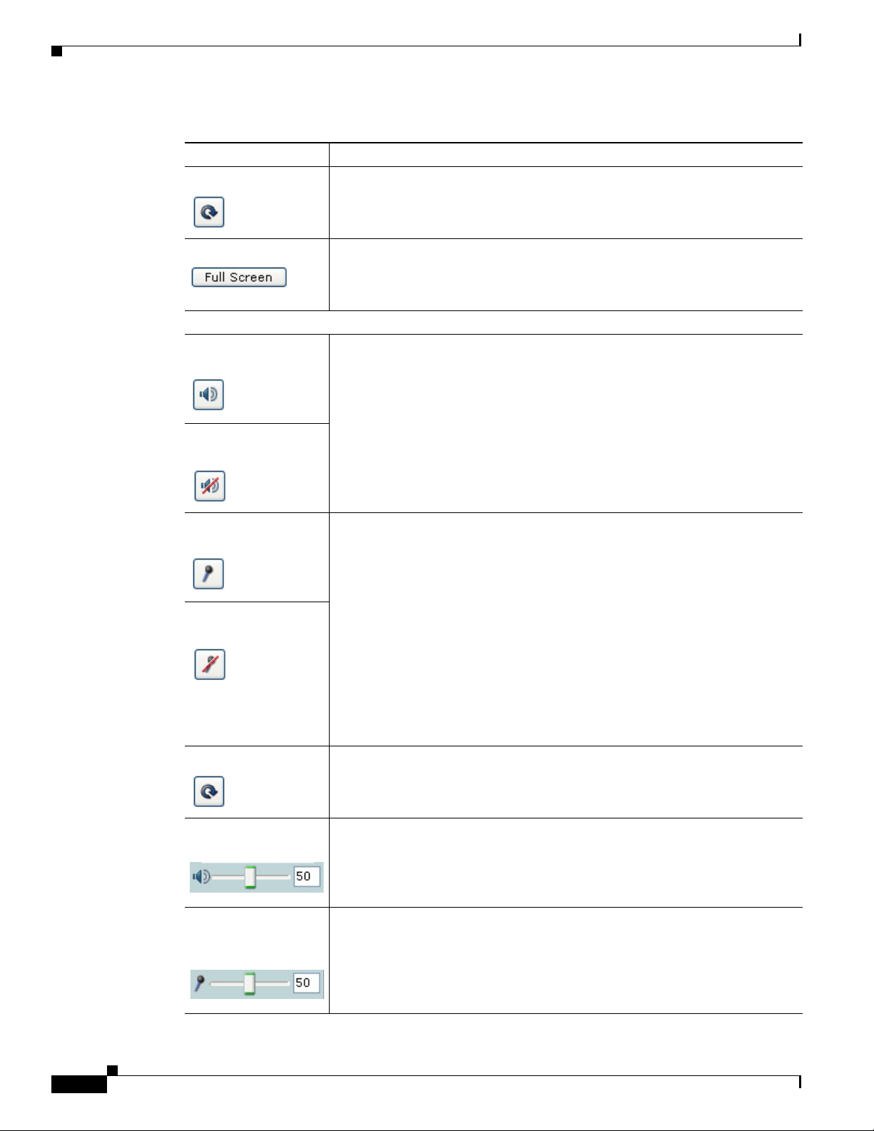
Chapter 4 Viewing Live Video
Table 4-1 Camera Video/Control Window Controls (continued)
Control Description
Restore button Displays the default video image, which is not rotated and not reversed.
Full Screen button Displays the video image in full screen mode.
To return to normal display mode, click the full screen image.
Audio controls
Disable Speaker
toggle button
Enable Speaker toggle
button
Click the Disable Speaker button to mute audio that is sent from the IP camera
to the PC that you are using. The button changes to the Enable Speaker button.
Click the Enable Speaker button to unmute audio. The button changes to the
Disable button.
Mute Microphone
toggle button
Click the Mute Microphone button to mute the audio stream that is captured
and sent to the IP camera from the internal or external microphone of the PC
that you are using. When you click this button, the speaker that is attached to
the IP camera does not play audio that is transmitted from your PC.
Unmute Microphone
toggle button
Note If you are simultaneously accessing other IP cameras in different
browser sessions on the same PC, clicking this button in one browser
session does not mute the audio that the PC sends to the other IP
cameras.
When you click the Mute Microphone button, it changes to the Unmute
Microphone button. Click the Unmute Microphone button to unmute audio
that is sent to the IP camera. The button changes to the Mute Microphone
button.
Restore button Resets audio controls to their default values.
Speaker Volume slider
and field
When the speaker is unmuted, drag this slider to adjust the volume at which
your PC speakers play the audio from the IP camera, or enter a value from 0
through 100 and press the Enter key.
The default value is 50.
Microphone
Sensitivity slider and
field
Drag this slider to adjust the gain of the PC microphone (that is, how sensitive
it is to the audio that it picks up and that is sent to the IP camera), or enter a
value from 0 through 100 and press the Enter key.
The default value is 50.
4-4
Cisco Video Surveillance 4300E and 4500E High-Definition IP Camera User Guide
OL-25230-02
Page 73

Chapter 4 Viewing Live Video
Table 4-1 Camera Video/Control Window Controls (continued)
Control Description
Presets controls
Preset drop-down list Displays a list of preset positions that you have set for the IP camera. When
Set Current Preset as
Home button
you choose a preset position from this list, the IP camera moves to that
position.
Click this button to define the current IP pan and tilt camera position as its
home position.
Start Auto-Patrol
toggle button
Stop Auto-Patrol
toggle button
Add Preset Position
button
Delete Selected
Preset button
Pan/tilt controls
IP camera control
buttons
Click the Start Auto-Patrol button to start the patrol sequence. The button
changes to the Stop Auto-Patrol button. Click the Stop Auto-Patrol button to
stop a sequence that is executing. The button changes to the Start Auto-Patrol
button.
You define a patrol sequence as described in the “Patrol Sequence Window”
section on page 3-16.
Click this button to add the current IP camera position as a preset position.
In the pop-up box, enter a unique name for this position and click Save. The
name can contain from 1 to 64characters, which can be letters, numbers, and
special characters, but no spaces. Special characters are:
! % ( ) , - = @ _ ~
You can create up to 8 preset positions.
Click this button then click OK in the confirmation dialog box to delete the
preset position that appears in the Preset drop-down list.
To pan the IP camera, use the left or right arrow buttons.
To tilt the IP camera, use the up or down arrow buttons.
OL-25230-02
To move the IP camera to its home position, click the Go to Home Position
button, which is located in the middle of the group of arrow keys.
Pan and tilt functions require that the IP camera be installed with a pan/tilt
mount that supports the Pelco D protocol and that pan and tilt functions are
enabled. For more information, see the
“Pan Tilt Settings Window” section on
page 3-10.
Cisco Video Surveillance 4300E and 4500E High-Definition IP Camera User Guide
4-5
Page 74

Chapter 4 Viewing Live Video
Table 4-1 Camera Video/Control Window Controls (continued)
Control Description
Right Arrow toggle
button
Left Arrow toggle
button
Pan/tilt speed controls
Note These controls appear when you click the Right Arrow in the Pan/Tilt area.
Pan Speed slider To control the relative speed of panning for the IP camera, drag the slider, or
Click the Right Arrow to display the pan/tilt speed controls. The button
changes to the Left Arrow button.
Click the Left Arrow button to hide the pan/tilt speed controls. The button
changes to the Right Arrow button.
enter a value from 1 through 100 and press the Enter key. A higher value
increases pan speed and a lower value decreases pan speed.
The default value is 50.
Tilt Speed slider To control the relative speed of tilting for the IP camera, drag the slider, or
enter a value from 1 through 100 and press the Enter key. A higher value
increases tilt speed and a lower value decreases tilt speed.
The default value is 50.
Restore button Click this button to set the pan speed and tilt speed to their default values.
Motion detection
Note If you configure MJPEG for video control, the motion detection functions are available only if
you disable the primary video stream (channel 1). For information about enabling and disabling
video streams, see the
Up Arrow toggle
button
“Streaming Settings Window” section on page 3-3.
Click the Up Arrow to display the motion detection controls. The button
changes to the Down Arrow button.
Click the Down Arrow button to hide the motion detection controls. The button
Down Arrow toggle
changes to the Up Arrow button.
button
4-6
Cisco Video Surveillance 4300E and 4500E High-Definition IP Camera User Guide
OL-25230-02
Page 75

Chapter 4 Viewing Live Video
Table 4-1 Camera Video/Control Window Controls (continued)
Control Description
Motion detection controls
Note These controls appear when you click the Up Arrow in the Motion Detection area and are
Enable Motion
Detection check box
available only viewing the primary (H.264) stream.
Enables the motion detection feature and displays a grid over the video image.
When motion detection is enabled, the IP camera monitors activity in the video
field areas that you specify. If activity at a defined level occurs in any of these
areas, the IP camera generates an alert and takes the actions that are configured
as described in the
To designate specific areas that the IP camera monitors for activity, select the
areas by clicking each grid cell over the area. A red border indicates a selected
area. To deselect an area, click it again.
You can configure the following levels for areas that the IP camera monitors
for activity:
• Sensitivity—Designates the relative amount of activity that the IP camera
must detect in the area before it generates an alert. A lower value means
that more, or faster, activity is required to trigger an alert. A higher value
means that less, or slower, activity is required. The default value is 50.
• Threshold—Designates the percentage of pixels that the IP camera must
identify as changed in the area before it generates an alert. The camera
detects pixel changes at the defined sensitivity level. The default threshold
value is 50.
“Event Notification Window” section on page 3-11.
To configure sensitivity or threshold, right-click a grid cell that has a red
border and then drag the Sensitivity and Threshold sliders to the desired
values. Alternatively, enter a value from 1 through 100 for an option and press
the Enter key. To reset the sensitivity and threshold to their default values of
50, click Restore. These configuration settings affect the cell that you select.
If the cell is part of a group of horizontally or vertically (but not diagonally)
adjacent cells, the settings affect all cells in the group.
OL-25230-02
Cisco Video Surveillance 4300E and 4500E High-Definition IP Camera User Guide
4-7
Page 76

Chapter 4 Viewing Live Video
Table 4-1 Camera Video/Control Window Controls (continued)
Control Description
Full Screen check
box
Restore button Deselects all areas in the video field that you have selected for motion
Save Settings button Save the current motion detection configuration.
Becomes available when you click check Enable Motion Detection check box.
Check the Full Screen check box to cause the IP camera to examine the entire
video field for activity.
You can configure the following items for this video field:
• Sensitivity—Designates the relative amount of activity that the IP camera
must detect in the area before it generates an alert. A lower value means
that more, or faster, activity is required to trigger an alert. A higher value
means that less, or slower, activity is required. The default value is 50.
• Threshold—Designates the percentage of pixels that the IP camera must
identify as changed in the area before it generates an alert. The camera
monitors for pixel changes at the defined sensitivity level. The default
threshold value is 50.
To configure sensitivity or threshold, right-click anywhere in the video field
border and then drag the Sensitivity and Threshold sliders to the desired
values. Alternatively, enter a value from 1 through 100 for an option and press
the Enter key. To reset the sensitivity and threshold to their default values of
50, click Restore.
detection monitoring.
4-8
Cisco Video Surveillance 4300E and 4500E High-Definition IP Camera User Guide
OL-25230-02
Page 77

CHAPTER
5
Troubleshooting
This chapter describes some common problems that may be encountered while using the IP camera and
provides possible solutions.
Symptom Cannot connect to an IP camera through a web browser.
Possible Cause You are not using a supported PC operating system or web browser, you entered an
incorrect IP address for the IP camera, the PC that you are using is not on the same LAN as the IP
camera, you are entering an invalid port number for an HTTP or HTTPS connection, or you are
trying to access the IP camera from a device with an IP address that is restricted from access.
Recommended Action Make sure that you are using a PC that is running Microsoft Windows XP with
Service Pack 2 or higher, or Microsoft Windows 7 Enterprise x64, and that you are using Internet
Explorer 8.0 (32-bit only). Make sure that you enter the correct IP address. If you are connecting
through a LAN, make sure that the PC is on the same network as the IP camera. If you are connecting
through the Internet, make sure to enter the correct port number. Make sure that the device does not
have an IP address that is restricted from access (see the
page 3-19.)
“IP Addressing Window” section on
OL-25230-02
Symptom Cannot log in to the IP camera as the administrator.
Possible Cause You are entering the log in credentials incorrectly or have forgotten the administrator
password.
Recommended Action The administrator user name is admin and the password is the one that you
configured. Both credentials are case sensitive, so make sure to enter them exactly as they are
configured. If you forget the administrator password, you must perform a factory reset as described
in the
“Resetting the IP Camera” procedure on page 2-11, then reconfigure the IP camera. If you
take these actions, do not use the Upload option in the Maintenance window to reload a saved
configuration file because that process restores the password that you forgot.
Cisco Video Surveillance 4300E and 4500E High-Definition IP Camera User Guide
5-1
Page 78

Chapter 5 Troubleshooting
Symptom The motion detection feature does not send e-mail alerts.
Possible Cause The e-mail alert feature is not properly configured or the SMTP server that the IP
camera uses to send the e-mail may be filtering e-mail to prevent spam from being sent from your
server.
Recommended Action Configure e-mail alerts as described in the “Event Notification Window”
section on page 3-11. Try using a different SMTP server or contact your ISP to see if SMTP access
is being blocked.
Symptom The motion detection feature is configured but video files that are provided in e-mail alerts do
not show moving objects.
Possible Cause The motion detection feature does not actually detect motion. It compares frames to
see if they are different. Major differences between frames are assumed to be caused by moving
objects, but the motion detector can also be triggered by sudden changes in light level or movement
of the IP camera itself.
Recommended Action Try to avoid situations with sudden changes in light level and do not bump or
move the IP camera. The motion detection feature works best when the IP camera is mounted
securely in locations where there is steady. This feature may not work properly if the IP camera is
outdoors.
Symptom Blurry images when viewing video.
Possible Cause The lens may be dirty, back focus may not be adjusted properly, or video settings may
not be configured for optimal clarity.
Recommended Action Clean the lens on the IP camera. Adjust the back focus as described in the
“Adjusting Back Focus on the IP Camera” section on page 2-10. Configure options for video as
described in the “Streaming Settings Window” section on page 3-3.
5-2
Cisco Video Surveillance 4300E and 4500E High-Definition IP Camera User Guide
OL-25230-02
Page 79

INDEX
Numerics
802.1x Settings window
options 3-25
overview 3-25
A
About link 2-8
Account Initialization window
options 3-29
overview 3-28
action
triggered by event 3-11
ActiveX controls 2-8
Administration windows 3-28, 3-35
Administrator user type 5-1
Analytics
See Cisco video analytics
audio
controls in Camera Video/Control window 4-4
settings 3-6
Available list 3-17
B
back focus
adjusting 2-10
focus ring 2-10
backing up, configuration of IP camera 3-31
Basic Settings window
options 3-19
overview 3-18
Baud rate, for pan/tilt device 3-10
bit rate, of video 3-5
Bonjour, enabling on camera 3-22
brightness 4-2
C
camera
See IP camera
Camera Settings window
options 3-7
overview 3-6
Camera Video/Control window
accessing 4-1
description 2-9
displaying 2-8
CDP (Cisco Discovery Protocol), enabling on
camera
Cisco video analytics
Cisco Video Surveillance IP Camera
C mount lens 1-3, 2-2
configuration, guidelines 3-1
configuration windows
3-22
configuration windows 3-18
supported camera model 1-1
See IP camera
802.1x Settings window 3-25
accessing 2-6, 3-1
Account Initialization window 3-28
Administration windows 3-28
Analytics window 3-18
Basic Settings window 3-18
Camera Settings window 3-6
OL-25230-02
Cisco Video Surveillance 4300E and 4500E High-Definition IP Camera User Guide
IN-1
Page 80

Index
Device Processes window 3-34
Discovery Settings window 3-22
Event Notification window 3-11
Feature Setup windows 3-2
Firmware Settings window 3-33
IO Ports Settings window 3-9
IP Addressing window 3-19
IP Filter Settings window 3-26
Local Log window 3-38
Log Setup Settings window 3-36
Log windows 3-35
Maintenance Settings window 3-31
Network Setup windows 3-18
options 3-2
overview 3-1
Pan Tilt Settings window 3-10
Password Complexity window 3-35
Patrol Sequence window 3-16
QoS Settings window 3-27
SNMP Settings window 3-23
Streaming Settings window 3-3
time out 3-1
Time Settings window 3-20
User Settings window 3-30
Video Overlay Settings window 3-8
connecting, to the IP camera
after the first time 2-6
for the first time 2-5
PC requirements for 2-5, 2-6
secure connection 2-7
contrast 4-2
CS mount lens 1-3, 2-2
D
data bits, for pan/tilt device 3-10
date and time
configuring manually 3-21
updating through NTP server 3-21
day
filter 3-6
mode 3-6
daylight saving time, adjustment for 3-21
DC auto iris lens
connecting 1-3
connector pinouts 1-6
decrypting video files 2-14
Device Processes window
options 3-34
overview 3-34
DHCP, obtaining IP address through 2-5, 3-20
Differentiated Services (DiffServ) 3-28
Discovery Settings window
options 3-22
overview 3-22
DNS server
primary 3-20
secondary 3-20
download decryption utility 2-12
dual streaming 3-3
dwell time 3-17
E
e-mail notification
configuring 3-13, 3-14
From field 3-15
recipients 3-15
event
actions
email notification 3-11
FTP notification 3-11
HTTP notification 3-11
output port state change 3-11
syslog server message 3-11
overview 3-11
trigger types 3-12
Event Notification window
IN-2
Cisco Video Surveillance 4300E and 4500E High-Definition IP Camera User Guide
OL-25230-02
Page 81

Index
options 3-12
overview 3-11
F
factory default configurations, resetting 3-32
factory default configurations, restoring 3-32
factory reset 2-11
Feature Setup windows 3-2
firmware
upgrading 3-33, 3-34
version in IP camera 3-34
Firmware Settings window
options 3-33
overview 3-33
flash drive
deleting files from 2-13
downloading files from 2-13
formatting 2-12
focus, back focus 2-10
formatting USB flash drive 2-12
FTP notification
configuring 3-15
G
gateway, for IP camera 3-20
General purpose input/output (GPIO) port 1-5
H
help, for IP camera windows 2-8
home position, moving IP camera to 4-5
Home window
accessing 2-6
description 2-6, 2-7, 2-9
displaying 2-8
HTTP
accessing camera through 2-7
allowing access through 2-6, 3-29
default port 3-29
port 3-29
HTTPS
accessing camera through 2-7
allowing access through 3-29
default port 3-29
port 3-29
hue 4-3
I
input device, connecting 2-4
input ports
connecting devices to 2-4
on IP camera 1-5
state change 3-11
installing
IP camera 2-1
speaker 2-3
IO Ports Settings window
options 3-9
overview 3-9
IP address
controlling access by 3-26
default for IP camera 2-5, 2-6, 2-7
fixed 3-20
obtaining from DCHP server 2-5
obtaining through DHCP 3-20
static 3-20
IP Addressing window
options 3-20
overview 3-19
IP camera
accessing through a web browser 2-5, 2-6
back focus of 2-10
connecting to after the first time 2-6
connecting to for the first time 2-5
OL-25230-02
Cisco Video Surveillance 4300E and 4500E High-Definition IP Camera User Guide
IN-3
Page 82

Index
controlling access to 3-26
day mode 3-6
DC auto iris lens connector pinouts 1-6
description 1-3
focus 2-10
General purpose input/output (GPIO) port 1-5
installation 2-1
LAN port on 1-4
lens 1-3, 2-2
local storage, managing 2-11
logging in to 2-7
logging out of 2-8
MAC address 3-33
mounting 2-5
name 3-19
night mode 3-6
overview 1-1
package contents 1-6
panning 4-3, 4-5
power connection 1-5
powering off 2-11
powering on 2-11
rebooting 3-32
resetting 1-5
restarting 3-32
restoring factory default configurations 3-32
tilting 4-3, 4-5
time zone 3-21
troubleshooting 5-1
windows 2-6, 2-9
IP Filter Settings window
options 3-27
overview 3-26
PoE 1-4
power 1-4
lens
attaching to IP camera 2-2
C mount 2-2
CS mount 2-2
DC auto iris 1-3, 2-2
for IP camera 1-3
type 1-3
live video
viewing
through home window 4-1
through third-party device or software 4-1
See also video
Local Log window
options 3-38
overview 3-38
local storage
decrypting video files 2-14
managing 2-11
USB download decryption utility 2-12
USB flash drive
deleting files from 2-13
downloading files from 2-13
formatting 2-12
log file
sending to Syslog server 3-36
storage of 3-35
viewing 3-38
log in, to IP camera 2-7
log out, of IP camera 2-8
Log Setup Settings window
options 3-36
overview 3-36
L
LAN port 1-4
LED
Network Activity 1-4
Cisco Video Surveillance 4300E and 4500E High-Definition IP Camera User Guide
IN-4
M
MAC address, of IP camera 3-33
Maintenance Settings window
OL-25230-02
Page 83

Index
options 3-32
overview 3-31
microphone
external 3-7
internal 1-3, 3-7
muting PC 4-4
on camera 1-3
PC 4-4
sensitivity 4-4
use 3-6
motion detection
accessing controls 4-6
enabling 4-7
sensitivity 4-7, 4-8
threshold 4-7, 4-8
Motion detection controls 4-7
mounting, IP camera 2-5
multicast
address 3-5
enabling 3-5
port 3-5
muting
PC microphone 4-4
PC speaker 4-4
N
name, of IP camera 3-19, 3-33
network, activity 1-4
Network Activity LED 1-4
Network Setup windows 3-18
night
filter 3-6
mode 3-6
O
output device, connecting 2-4
output ports
connecting devices to 2-4
on IP camera 1-5
power on state 3-9
P
package contents 1-6
pan, tilt, zoom
See PTZ
panning 4-3, 4-5
Pan Tilt Settings window
options 3-10
overview 3-10
parity, for pan/tilt device 3-10
password
complexity 3-35
configuring requirements for 3-35
for primary SMTP server 3-14
for secondary SMTP server 3-15
for user 3-30
hardening 3-35
recovering 5-1
requirements for 2-6, 3-30
Password Complexity window
options 3-35
overview 3-35
patrol sequence
dwell time 3-17
maximum number of steps 3-16
overview 3-16
Selected list 3-17
steps 3-17
Patrol Sequence window
options 3-17
overview 3-16
pinouts, for DC auto iris lens connector 1-6
port number 2-7
power
OL-25230-02
Cisco Video Surveillance 4300E and 4500E High-Definition IP Camera User Guide
IN-5
Page 84

Index
port for power adapter 1-5
powering off the IP camera 2-11
powering on the IP camera 2-11
Power over Ethernet (PoE) 2-1
terminal block 2-4
power adapter
connecting 2-4
supported 2-1
Power over Ethernet (PoE) 1-4, 2-1
processes
descriptions 3-34
stopping 3-34
Q
QoS Settings window
options 3-27
overview 3-27
quality of service 3-27
R
rebooting, IP camera 2-11, 3-32
Refresh link 2-8
reset
factory default values 2-11
reboot 2-11
Reset button 1-5
resetting, factory default configurations 3-32
resetting the IP camera 1-5
restarting, IP camera 3-32
restoring, factory default configurations 3-32
RS-232 ports, connecting devices to 2-4
S
saturation 4-3
secure connection 2-7
security
controlling processes 3-34
password hardening 3-35
stopping processes 3-34
Selected list 3-17
sensitivity, for motion detection 4-7, 4-8
Setup window
description 2-9
displaying 2-8
sharpness 4-2
SNMP, configuring 3-23
SNMP Settings window
options 3-23
overview 3-23
speaker
external 1-4
installing 2-3
volume 4-4
SSH
allowing access through 3-29
alternative port 3-29
default port 3-29
steps, in a patrol sequence 3-17
stop bits, for pan/tilt device 3-10
storage
decrypting video files 2-14
managing 2-11
USB download decryption utility 2-12
USB flash drive
deleting files from 2-13
downloading files from 2-13
formatting 2-12
Streaming Settings window
options 3-4
overview 3-3
subnet mask, of IP camera 3-20
Syslog server 3-36
IN-6
Cisco Video Surveillance 4300E and 4500E High-Definition IP Camera User Guide
OL-25230-02
Page 85

Index
T
terminal block 2-4
text overlay, on video 3-8
threshold, for motion detection 4-7, 4-8
tilting 4-3, 4-5
time out, of configuration windows 3-1
Time Settings window
options 3-21
overview 3-20
time stamp, on video 3-8
time zone, of IP camera 3-21
trigger, for event 3-12
troubleshooting
administrator password recovery 5-1
alerts 5-2
cannot access IP camera through browser 5-1
motion detection 5-2
U
USB download decryption utility 2-12
USB storage
decrypting video files 2-14
managing 2-11
USB download decryption utility 2-12
USB flash drive
deleting files from 2-13
downloading files from 2-13
formatting 2-12
user, password 3-30
user name, requirements for 3-30
User Settings window
options 3-30
overview 3-30
bit rate 3-5
primary stream 3-3
quality 3-5
secondary stream 3-3
text overlay 3-8
time stamp on 3-8
viewing live
through Home window 4-1
through third-party device or software 4-1
See also live video
video codec
controls in Camera Video/Control window 4-1
display in Streaming Settings window 3-5
video image
controls in Camera Video/Control window 4-2
optimizing for lighting condition 3-6
Video Overlay Settings window
options 3-8
overview 3-8
video resolution
configuration guidelines 3-3
controls in Camera Video/Control window 4-2
View Video link 2-8
W
white balance 4-2
V
video
OL-25230-02
Cisco Video Surveillance 4300E and 4500E High-Definition IP Camera User Guide
IN-7
Page 86

Index
IN-8
Cisco Video Surveillance 4300E and 4500E High-Definition IP Camera User Guide
OL-25230-02
 Loading...