

Page 1

Catalyst 3750, 3560, 3550, 2975, 2970, and 2960 Switch System Message Guide
Cisco IOS Release 12.2(46)SE and Release 12.2(46)EX
November 2008
Americas Headquarters
Cisco Systems, Inc.
170 West Tasman Drive
San Jose, CA 95134-1706
USA
http://www.cisco.com
Tel: 408 526-4000
800 553-NETS (6387)
Fax: 408 527-0883
Text Part Number: OL-8551-04
Page 2

THE SPECIFICATIONS AND INFORMATION REGARDING THE PRODUCTS IN THIS MANUAL ARE SUBJECT TO CHANGE WITHOUT NOTICE. ALL
STATEMENTS, INFORMATION, AND RECOMMENDATIONS IN THIS MANUAL ARE BELIEVED TO BE ACCURATE BUT ARE PRESENTED WITHOUT
WARRANTY OF ANY KIND, EXPRESS OR IMPLIED. USERS MUST TAKE FULL RESPONSIBILITY FOR THEIR APPLICATION OF ANY PRODUCTS.
THE SOFTWARE LICENSE AND LIMITED WARRANTY FOR THE ACCOMPANYING PRODUCT ARE SET FORTH IN THE INFORMATION PACKET THAT
SHIPPED WITH THE PRODUCT AND ARE INCORPORATED HEREIN BY THIS REFERENCE. IF YOU ARE UNABLE TO LOCATE THE SOFTWARE LICENSE
OR LIMITED WARRANTY, CONTACT YOUR CISCO REPRESENTATIVE FOR A COPY.
The Cisco implementation of TCP header compression is an adaptation of a program developed by the University of California, Berkeley (UCB) as part of UCB’s public
domain version of the UNIX operating system. All rights reserved. Copyright © 1981, Regents of the University of California.
NOTWITHSTANDING ANY OTHER WARRANTY HEREIN, ALL DOCUMENT FILES AND SOFTWARE OF THESE SUPPLIERS ARE PROVIDED “AS IS” WITH
ALL FAULTS. CISCO AND THE ABOVE-NAMED SUPPLIERS DISCLAIM ALL WARRANTIES, EXPRESSED OR
LIMITATION, THOSE OF MERCHANTABILITY, FITNESS FOR A PARTICULAR PURPOSE AND NONINFRINGEMENT OR ARISING FROM A COURSE OF
DEALING, USAGE, OR TRADE PRACTICE.
IN NO EVENT SHALL CISCO OR ITS SUPPLIERS BE LIABLE FOR ANY INDIRECT, SPECIAL, CONSEQUENTIAL, OR INCIDENTAL DAMAGES, INCLUDING,
WITHOUT LIMITATION, LOST PROFITS OR LOSS OR DAMAGE TO DATA ARISING OUT OF THE USE OR INABILITY TO USE THIS MANUAL, EVEN IF CISCO
OR ITS SUPPLIERS HAVE BEEN ADVISED OF THE POSSIBILITY OF SUCH DAMAGES.
CCDE, CCENT, Cisco Eos, Cisco Lumin, Cisco Nexus, Cisco StadiumVision, Cisco TelePresence, Cisco WebEx, the Cisco logo, DCE, and Welcome to the Human Network
are trademarks; Changing the Way We Work, Live, Play, and Learn and Cisco Store are service marks; and Access Registrar, Aironet, AsyncOS, Bringing the Meeting To
You, Catalyst, CCDA, CCDP, CCIE, CCIP, CCNA, CCNP, CCSP, CCVP, Cisco, the Cisco
Cisco
Systems Capital, the Cisco Systems logo, Cisco Unity, Collaboration Without Limitation, EtherFast, EtherSwitch, Event Center, Fast Step, Follow Me Browsing,
FormShare, GigaDrive, HomeLink, Internet Quotient, IOS, iPhone, iQuick Study, IronPort, the IronPort
MeetingPlace Chime Sound, MGX, Networkers, Networking Academy, Network Registrar, PCNow, PIX, PowerPanels, ProConnect, ScriptShare, SenderBase, SMARTnet,
Spectrum Expert, StackWise, The Fastest Way to Increase Your Internet Quotient, TransPath, WebEx, and the WebEx
and/or its affiliates in the United States and certain other countries.
All other trademarks mentioned in this document or website are the property of their respective owners. The use of the word partner does not imply a partnership relationship
between Cisco and any other company. (0809R)
Any Internet Protocol (IP) addresses used in this document are not intended to be actual addresses. Any examples, command display output, and figures included in the
document are shown for illustrative purposes only. Any use of actual IP addresses in illustrative content is unintentional and coincidental.
Catalyst 3750, 3560, 3550, 2975, 2970, and 2960 Switch System Message Guide
© 2007–2008 Cisco Systems, Inc. All rights reserved.
Certified Internetwork Expert logo, Cisco IOS, Cisco Press, Cisco Systems,
logo, LightStream, Linksys, MediaTone, MeetingPlace,
IMPLIED, INCLUDING, WITHOUT
logo are registered trademarks of Cisco Systems, Inc.
Page 3

CONTENTS
Preface vii
Audience i-vii
Purpose i-vii
Conventions i-vii
Related Publications i-viii
Obtaining Documentation, Obtaining Support, and Security Guidelines i-x
CHAPTER
CHAPTER
2 System Message Overview 2-1
How to Read System Messages 2-1
Error Message Traceback Reports 2-7
Output Interpreter 2-7
Bug Toolkit 2-7
Contacting TAC 2-7
3 Message and Recovery Procedures 3-1
ACLMGR Messages 3-3
AUTOQOS Messages 3-8
BACKUP_INTERFACE Messages 3-8
BADTRANSCEIVER Messages 3-9
BSPATCH Messages 3-9
CFGMGR Messages 3-10
CMP Messages 3-13
DHCP_SNOOPING Messages 3-14
DHCP_SNOOPING_CAT3550 Messages 3-17
OL-8551-04
DOT1Q_TUNNELLING Messages 3-18
DOT1X Messages 3-18
DOT1X_SWITCH Messages 3-19
DTP Messages 3-23
DWL Messages 3-24
EC Messages 3-25
ENVIRONMENT Messages 3-29
ETHCNTR Messages 3-30
Catalyst 3750, 3560, 3550, 2975, 2970, and 2960 Switch System Message Guide
iii
Page 4

Contents
EXPRESS_SETUP Messages 3-34
FM Messages 3-35
FRNTEND_CTRLR Messages 3-44
GBIC Messages 3-45
GBIC_SECURITY Messages 3-48
GBIC_SECURITY_CRYPT Messages 3-51
GBIC_SECURITY_UNIQUE Messages 3-52
GIGASTACK Messages 3-53
HARDWARE Messages 3-54
HLFM Messages 3-56
HPSECURE Messages 3-57
IDBMAN Messages 3-58
IGMP_QUERIER Messages 3-61
ILPOWER Messages 3-62
IMAGEMGR Messages 3-69
IP_DEVICE_TRACKING_HA Messages 3-70
L2TM Messages 3-71
L3TCAM Messages 3-71
MAC_LIMIT Messages 3-72
MAC_MOVE Messages 3-73
NETWORK_PORT_SATELLITE Messages 3-73
PAGP_DUAL_ACTIVE Messages 3-74
PBR Messages 3-75
PHY Messages 3-77
PIMSN Messages 3-79
PLATFORM Messages 3-80
PLATFORM_FBM Messages 3-81
PLATFORM_HCEF Messages 3-82
PLATFORM_HPLM Messages 3-83
PLATFORM _IPC Messages 3-84
iv
PLATFORM_IPv6 Message 3-85
PLATFORM_PBR Messages 3-86
PLATFORM_PM Messages 3-88
PLATFORM_RPC Messages 3-89
PLATFORM_SPAN Messages 3-91
Catalyst 3750, 3560, 3550, 2975, 2970, and 2960 Switch System Message Guide
OL-8551-04
Page 5

PLATFORM_UCAST Messages 3-92
PLATFORM_VLAN Messages 3-95
PLATFORM_WCCP Messages 3-96
PM Messages 3-97
PORT_SECURITY Messages 3-105
QATM Messages 3-107
QM Messages 3-108
QOSMGR Messages 3-111
RMON Messages 3-117
SDM Messages 3-118
SPAN Messages 3-118
SPANTREE Messages 3-119
SPANTREE_FAST Messages 3-127
Contents
SPANTREE_VLAN_SW Messages 3-127
STACKMGR Messages 3-127
STORM_CONTROL Messages 3-130
SUPERVISOR Messages 3-131
SUPQ Messages 3-131
SW_DAI Messages 3-134
SW_MACAUTH Messages 3-137
SW_MATM Messages 3-138
SW_VLAN Messages 3-138
SWITCH_QOS_TB Messages 3-145
TCAMMGR Messages 3-146
UDLD Messages 3-148
UFAST_MCAST_SW Messages 3-150
VQPCLIENT Messages 3-150
WCCP Messages 3-152
WRLSCNTR Messages 3-152
I
NDEX
OL-8551-04
Catalyst 3750, 3560, 3550, 2975, 2970, and 2960 Switch System Message Guide
v
Page 6

Contents
vi
Catalyst 3750, 3560, 3550, 2975, 2970, and 2960 Switch System Message Guide
OL-8551-04
Page 7

Audience
Purpose
Preface
This guide is for the networking professional managing the Catalyst 3750, 3560, 3550, 2975, 2970, and
2960 switch or switch stack, hereafter referred to as the switch. Before using this guide, you should have
experience working with the Cisco IOS software and the switch software features.
This guide describes only the Catalyst 3750, 3560, 3550, 2975, 2970, and 2960 switch-specific system
messages that you might encounter. For a complete list of Cisco IOS system error messages, see the
Cisco IOS Software System Error Messages, Cisco IOS Release 12.2.
This guide does not describe how to install your switch or how to configure software features on your
switch. It also does not provide detailed information about commands that have been created or changed
for use by the switch. For hardware installation information, see the hardware installation guide that
shipped with your switch. For software information, see the software configuration guide and the
command reference for this release.
For documentation updates, see the release notes for this release.
Conventions
This publication uses these conventions to convey instructions and information:
Command descriptions use these conventions:
• Commands and keywords are in boldface text.
• Arguments for which you supply values are in italic.
• Square brackets ([ ]) mean optional elements.
• Braces ({ }) group required choices, and vertical bars ( | ) separate the alternative elements.
• Braces and vertical bars within square brackets ([{ | }]) mean a required choice within an optional
element.
OL-8551-04
Catalyst 3750, 3560, 3550, 2975, 2970, and 2960 Switch System Message Guide
vii
Page 8

Related Publications
Interactive examples use these conventions:
• Terminal sessions and system displays are in screen font.
• Information you enter is in boldf ace screen font.
• Nonprinting characters, such as passwords or tabs, are in angle brackets (< >).
Notes use this convention and symbol:
Note Means reader take note. Notes contain helpful suggestions or references to materials not in this manual.
Related Publications
These documents provide complete information about the switch and are available from this Cisco.com
site:
Catalyst 3750 switch
http://www.cisco.com/en/US/products/hw/switches/ps5023/tsd_products_support_series_home.html
Preface
Catalyst 3560 switch
http://www.cisco.com/en/US/products/hw/switches/ps5528/tsd_products_support_series_home.html
Catalyst 3550 switch
http://www.cisco.com/en/US/products/hw/switches/ps646/tsd_products_support_series_home.html
Catalyst 2975 switch
http://www.cisco.com/en/US/products/ps10081/tsd_products_support_series_home.html
Catalyst 2970 switch
http://www.cisco.com/en/US/products/hw/switches/ps5206/tsd_products_support_series_home.html
Catalyst 2960 switch
http://www.cisco.com/en/US/products/ps6406/tsd_products_support_series_home.html
Note Before installing, configuring, or upgrading the switch, see these documents:
• For initial configuration information, see the “Using Express Setup” chapter in the getting started
guide or the “Configuring the Switch with the CLI-Based Setup Program” appendix in the hardware
installation guide.
• For device manager requirements, see the “System Requirements” section in the release notes (not
orderable but available on Cisco.com).
• For Network Assistant requirements, see the Getting Started with Cisco Network Assistant (not
orderable but available on Cisco.com).
• For cluster requirements, see the Release Notes for Cisco Network Assistant (not orderable but
available on Cisco.com).
viii
• For upgrade information, see the “Downloading Software” section in the release notes.
Catalyst 3750, 3560, 3550, 2975, 2970, and 2960 Switch System Message Guide
OL-8551-04
Page 9

Preface
Related Publications
See these documents for other information about the switch:
• Release Notes for the Catalyst 3750, 3560, 3550, 2970, and 2960 Switches
• Catalyst 3750, 3560, 3550, 2970, and 2960 Switch System Message Guide
• Catalyst 3750 Switch Software Configuration Guide
• Catalyst 3750 Switch Command Reference
• Catalyst 3750 Switch Hardware Installation Guide
• Catalyst 3750 Switch Getting Started Guide
• Regulatory Compliance and Safety Information for the Catalyst 3750 Switch
• Catalyst 3560 Switch Software Configuration Guide
• Catalyst 3560 Switch Command Reference
• Catalyst 3560 Switch Hardware Installation Guide
• Catalyst 3560 Switch Getting Started Guide
• Regulatory Compliance and Safety Information for the Catalyst 3560 Switch
• Catalyst 3550 Multilayer Switch Software Configuration Guide
• Catalyst 3550 Multilayer Switch Command Reference
• Catalyst 3550 Multilayer Switch Hardware Installation Guide
• Catalyst 3550 Multilayer Switch Getting Started Guide
• Regulatory Compliance and Safety Information for the Catalyst 3550 Multilayer Switch
• Catalyst 2975 Switch Software Configuration Guide
• Catalyst 2975 Switch Command Reference
• Catalyst 2975 Switch Hardware Installation Guide
• Catalyst 2975 Switch Getting Started Guide
• Regulatory Compliance and Safety Information for the Catalyst 2975 Switch
• Release Notes for the Catalyst 2975 Switches
• Catalyst 2970 Switch Software Configuration Guide
• Catalyst 2970 Switch Command Reference
• Catalyst 2970 Switch Hardware Installation Guide
• Catalyst 2970 Switch Getting Started Guide
• Regulatory Compliance and Safety Information for the Catalyst 2970 Switch
• Catalyst 2960 Switch Software Configuration Guide
• Catalyst 2960 Switch Command Reference
• Catalyst 2960 Switch Hardware Installation Guide
OL-8551-04
• Catalyst 2960 Switch Getting Started Guide
• Regulatory Compliance and Safety Information for the Catalyst 2960 Switch
• Device manager online help (available on the switch)
• Getting Started with Cisco Network Assistant
• Release Notes for Cisco Network Assistant
• Cisco Small Form-Factor Pluggable Modules Installation Notes
Catalyst 3750, 3560, 3550, 2975, 2970, and 2960 Switch System Message Guide
ix
Page 10

Obtaining Documentation, Obtaining Support, and Security Guidelines
• Cisco CWDM GBIC and CWDM SFP Installation Note
• Cisco RPS 300 Redundant Power System Hardware Installation Guide
• Cisco RPS 675 Redundant Power System Hardware Installation Guide
• For information about the Network Admission Control (NAC) features, see the Network Admission
Control Software Configuration Guide (Not orderable but available on Cisco.com)
• These compatibility matrix documents are available from this Cisco.com site:
http://www.cisco.com/en/US/products/hw/modules/ps5455/products_device_support_tables_list.html
–
Cisco Gigabit Ethernet Transceiver Modules Compatibility Matrix
–
Cisco 100-Megabit Ethernet SFP Modules Compatibility Matrix
–
Cisco Small Form-Factor Pluggable Modules Compatibility Matrix
–
Compatibility Matrix for 1000BASE-T Small Form-Factor Pluggable Modules
Obtaining Documentation, Obtaining Support, and Security
Preface
Guidelines
For information on obtaining documentation, obtaining support, providing documentation feedback,
security guidelines, and also recommended aliases and general Cisco
What’s
New in Cisco Product Documentation, which also lists all new and revised Cisco technical
documentation, at:
http://www.cisco.com/en/US/docs/general/whatsnew/whatsnew.html
documents, see the monthly
Catalyst 3750, 3560, 3550, 2975, 2970, and 2960 Switch System Message Guide
x
OL-8551-04
Page 11

CHA PTER
2
System Message Overview
This guide describes the Catalyst 3750, 3560, 3550, 2975, 2970, and 2960-specific system messages.
During operation, the system software sends these messages to the console (and, optionally, to a logging
server on another system). Not all system messages indicate problems with your system. Some messages
are purely informational, whereas others can help diagnose problems with communications lines,
internal hardware, or the system software. This guide also includes error messages that appear when the
system fails.
For information about system messages that are not Catalyst 3750, 3560, 3550, 2975, 2970, or 2960
platform-specific, see the Cisco IOS Software System Messages for Cisco IOS Release 12.2S.
This chapter contains these sections:
• How to Read System Messages, page 2-1
• Error Message Traceback Reports, page 2-7
How to Read System Messages
System log messages can contain up to 80 characters and a percent sign (%), which follows the optional
sequence number or time stamp information, if configured. Messages are displayed in this format:
seq no:timestamp: %facility-severity-MNEMONIC:description (hostname-n) (only Catalyst 3750 and
2975 switches)
seq no:timestamp: %facility-severity-MNEMONIC:description (switches other than Catalyst 3750 and
2975 switches)
By default, a switch sends the output from system messages to a logging process. In a switch stack, stack
members append their hostnames to the output from system messages and redirect the output to the
logging process on the stack master.
Each system message begins with a percent sign (%) and is structured as follows:
%FACILITY-SEVERITY-MNEMONIC: Message-text
• FACILITY is a code consisting of two or more uppercase letters that show the facility to which the
message refers. A facility can be a hardware device, a protocol, or a module of the system software.
Table 2-1 lists Catalyst 3750, 3560, 3550, 2975, 2970, and 2960-specific facility codes. These
messages are described in Chapter 3, “Message and Recovery Procedures,” in alphabetical order by
facility code, with the most severe (lowest number) errors described first.
OL-8551-04
Catalyst 3750, 3560, 3550, 2975, 2970, and 2960 Switch System Message Guide
2-1
Page 12
Chapter 2 System Message Overview
How to Read System Messages
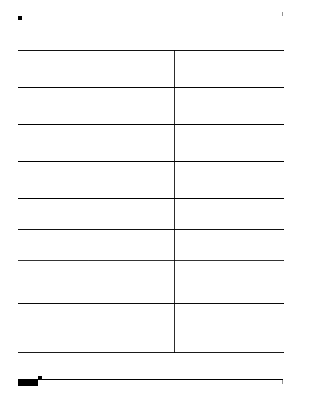
Ta b l e 2-1 Facility Codes
Facility Code Description Location
ACLMGR ACL manager “ACLMGR Messages” section on page 3-3
AUTOQOS Automatic quality of service
(auto-QoS) (only Catalyst 3550
switches)
BACKUP_INTERFACE Flex Links “BACKUP_INTERFACE Messages” section on
BADTRANSCEIVER Defective transceiver messages (only
3750 and 2975 switches)
BSPATCH Boot loader patch “BSPATCH Messages” section on page 3-9
CFGMGR Configuration manager (only Catalyst
3750 and 2975 switches)
CMP Cluster Membership Protocol “CMP Messages” section on page 3-13
DHCP_SNOOPING DHCP snooping “DHCP_SNOOPING Messages” section on
DHCP_SNOOPING_CAT3550 DHCP snooping (only Catalyst 3550
switches)
DOT1Q_TUNNELLING IEEE 802.1Q tunneling (only
Catalyst 3550 switches)
DOT1X IEEE 802.1x “DOT1X Messages” section on page 3-18
DOT1X_SWITCH IEEE 802.1x for switches “DOT1X_SWITCH Messages” section on
DTP Dynamic Trunking Protocol “DTP Messages” section on page 3-23
DWL Down-when-looped “DWL Messages” section on page 3-24
EC EtherChannel “EC Messages” section on page 3-25
ENVIRONMENT Environment (only Catalyst 3550
switches)
ETHCNTR Ethernet Controller “ETHCNTR Messages” section on page 3-30
EXPRESS_SETUP Express Setup “EXPRESS_SETUP Messages” section on
FM Feature manager (only Catalyst 3550
switches)
FRNTEND_CTRLR Front-end controller (only
Catalyst 3750 and 2975 switches)
GBIC Gigabit Interface Converter (GBIC)
module identification and validation
(only Catalyst 3550 switches)
GBIC_SECURITY GBIC module and small form-factor
pluggable (SFP) module security
GBIC_SECURITY_CRYPT GBIC and SFP module security “GBIC_SECURITY_CRYPT Messages” section
“AUTOQOS Messages” section on page 3-8
page 3-8
“BADTRANSCEIVER Messages” section on
page 3-9
“CFGMGR Messages” section on page 3-10
page 3-14
“DHCP_SNOOPING_CAT3550 Messages”
section on page 3-17
“DOT1Q_TUNNELLING Messages” section on
page 3-18
page 3-19
“ENVIRONMENT Messages” section on
page 3-29
page 3-34
“FM Messages” section on page 3-35
“FRNTEND_CTRLR Messages” section on
page 3-44
“GBIC Messages” section on page 3-45
“GBIC_SECURITY Messages” section on
page 3-48
on page 3-51
2-2
Catalyst 3750, 3560, 3550, 2975, 2970, and 2960 Switch System Message Guide
OL-8551-04
Page 13
Chapter 2 System Message Overview
How to Read System Messages
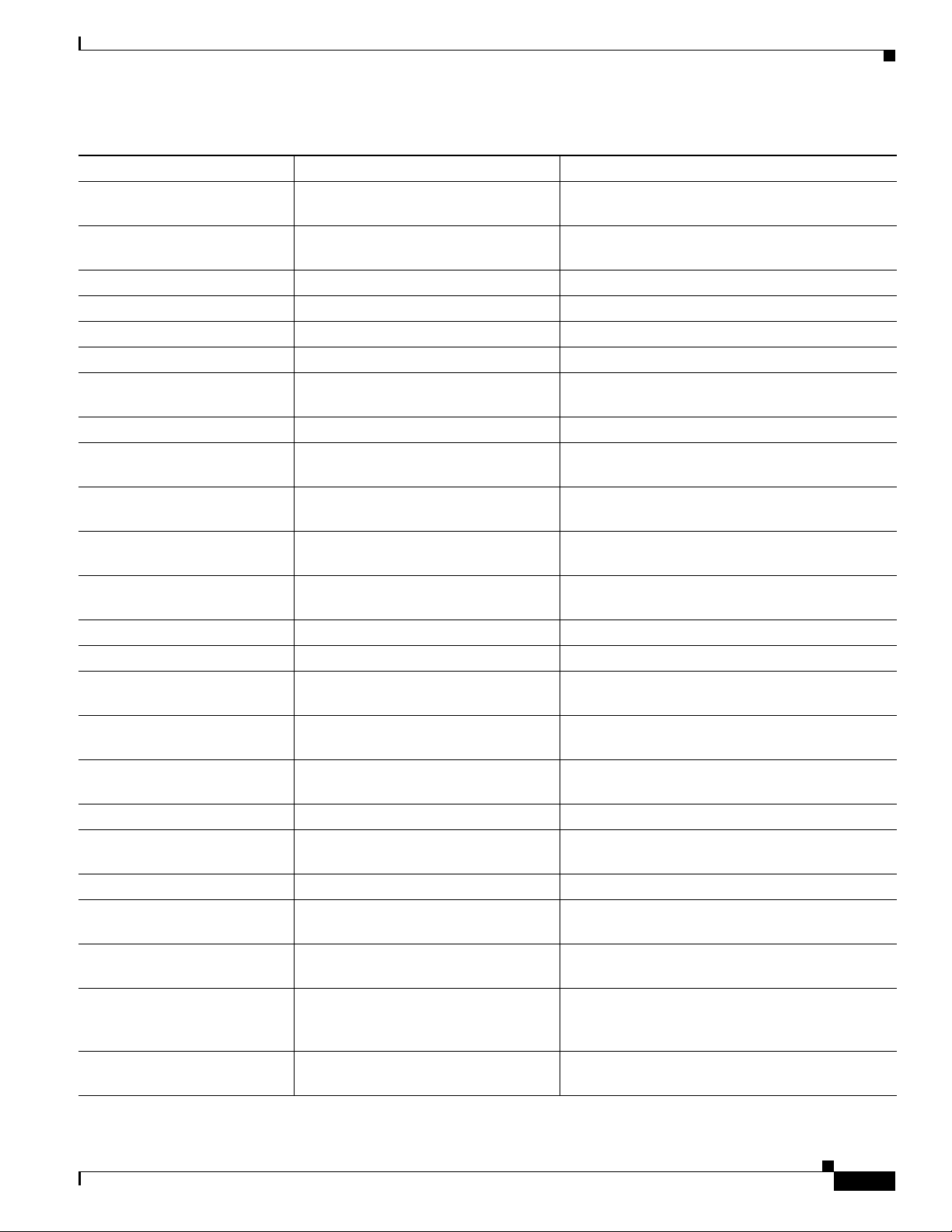
Table 2-1 Facility Codes (continued)
Facility Code Description Location
GBIC_SECURITY_UNIQUE GBIC and SFP module security “GBIC_SECURITY_UNIQUE Messages” section
on page 3-52
GIGASTACK GigaStack GBIC module
(Catalyst 3550 switch only)
HARDWARE Hardware “HARDWARE Messages” section on page 3-54
HLFM Local forwarding manager “HLFM Messages” section on page 3-56
HPSECURE Port security “HPSECURE Messages” section on page 3-57
IDBMAN Interface description block manager “IDBMAN Messages” section on page 3-58
IGMP_QUERIER Internet Group Management Protocol
(IGMP) querier
ILPOWER Power over Ethernet (PoE) “ILPOWER Messages” section on page 3-62
IMAGEMGR Image manager (only Catalyst 3750
and 2975 switches)
IP_DEVICE_TRACKING_HA IP device tracking for high availability “IP_DEVICE_TRACKING_HA Messages”
L2TM Layer 2 forwarding manager
(only Catalyst 3550 switches)
L3TCAM Layer 3 unicast routing manager
(only Catalyst 3550 switches)
MAC_LIMIT MAC address table entries “MAC_LIMIT Messages” section on page 3-72
MAC_MOVE Host activity “MAC_MOVE Messages” section on page 3-73
NETWORK_PORT_
SATELLITE
Network port satellite (only Catalyst
3550 switches)
PAGP_DUAL_ACTIVE Port Aggregation Protocol (PAgP)
dual-active detection
PBR Policy-based routing (PBR)
(only Catalyst 3550 switches)
PHY PHY “PHY Messages” section on page 3-77
PIMSN Protocol Independent Multicast (PIM)
snooping
PLATFORM Low-level platform-specific “PLATFORM Messages” section on page 3-80
PLATFORM_FBM Platform fallback bridging manager “PLATFORM_FBM Messages” section on
PLATFORM_HPLM Platform pseudo label manager “PLATFORM_HPLM Messages” section on
PLATFORM_IPC Platform inter-process communication
protocol (only Catalyst 3750 and 2975
switches)
PLATFORM_PBR Platform policy-based routing “PLATFORM_PBR Messages” section on
“GIGASTACK Messages” section on page 3-53
“IGMP_QUERIER Messages” section on
page 3-61
“IMAGEMGR Messages” section on page 3-69
section on page 3-70
“L2TM Messages” section on page 3-71
“L3TCAM Messages” section on page 3-71
“NETWORK_PORT_SATELLITE Messages”
section on page 3-73
“PAGP_DUAL_ACTIVE Messages” section on
page 3-74
“PBR Messages” section on page 3-75
“PIMSN Messages” section on page 3-79
page 3-81
page 3-83
“PLATFORM _IPC Messages” section on
page 3-84
page 3-86
OL-8551-04
Catalyst 3750, 3560, 3550, 2975, 2970, and 2960 Switch System Message Guide
2-3
Page 14
Chapter 2 System Message Overview
How to Read System Messages
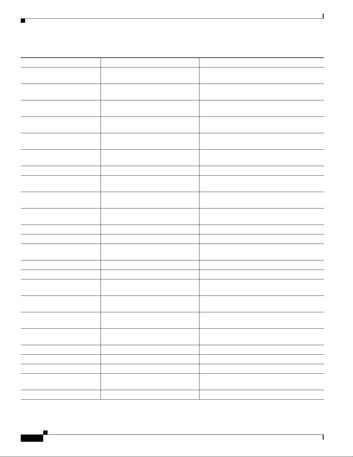
Table 2-1 Facility Codes (continued)
Facility Code Description Location
PLATFORM_PM Platform port manager “PLATFORM_PM Messages” section on
page 3-88
PLATFORM_RPC Platform remote procedure call (only
Catalyst 3750 and 2975 switches)
PLATFORM_SPAN Platform Switched Port Analyzer “PLATFORM_SPAN Messages” section on
PLATFORM_UCAST Platform unicast routing “PLATFORM_UCAST Messages” section on
PLATFORM_VLAN Platform VLAN “PLATFORM_VLAN Messages” section on
PLATFORM_WCCP Platform WCCP “PLATFORM_WCCP Messages” section on
PM Port manager “PM Messages” section on page 3-97
PORT_SECURITY Port security “PORT_SECURITY Messages” section on
QATM QoS and ACL TCAM manager (only
Catalyst 3550 switches)
QM QoS manager (only Catalyst 3550
switches)
QOSMGR QoS manager “QOSMGR Messages” section on page 3-111
RMON Remote Network Monitoring (RMON) “RMON Messages” section on page 3-117
SDM Switch Database Manager
(only Catalyst 3750 switches)
SPAN Switched Port Analyzer “SPAN Messages” section on page 3-118
SPANTREE Spanning Tree “SPANTREE Messages” section on page 3-119
SPANTREE_FAST Spanning-tree fast convergence “SPANTREE_FAST Messages” section on
SPANTREE_VLAN_SW Spanning-tree VLAN switch “SPANTREE_VLAN_SW Messages” section on
STACKMGR Stack manager (only Catalyst 3750 and
2975 switches)
STORM_CONTROL Storm control “STORM_CONTROL Messages” section on
SUPERVISOR Supervisor ASIC “SUPERVISOR Messages” section on page 3-131
SUPQ Supervisor queue “SUPQ Messages” section on page 3-131
SW_DAI Dynamic ARP inspection “SW_DAI Messages” section on page 3-133
SW_MACAUTH MAC address authentication (only
Catalyst 3750 and 3560 switches)
SW_VLAN VLAN manager “SW_VLAN Messages” section on page 3-137
“PLATFORM_RPC Messages” section on
page 3-89
page 3-91
page 3-92
page 3-95
page 3-96
page 3-105
“QATM Messages” section on page 3-107
“QM Messages” section on page 3-108
“SDM Messages” section on page 3-118
page 3-127
page 3-127
“STACKMGR Messages” section on page 3-127
page 3-130
“SW_MACAUTH Messages” section on
page 3-136
2-4
Catalyst 3750, 3560, 3550, 2975, 2970, and 2960 Switch System Message Guide
OL-8551-04
Page 15
Chapter 2 System Message Overview
How to Read System Messages
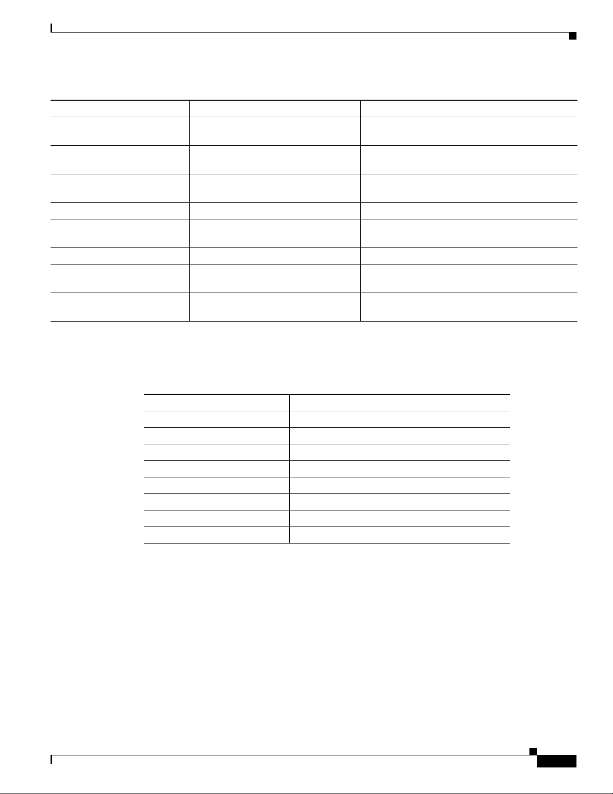
Table 2-1 Facility Codes (continued)
Facility Code Description Location
SW_MATM Mac address table manager (only
Catalyst 3550 switches)
SWITCH_QOS_TB QoS trusted boundary “SWITCH_QOS_TB Messages” section on
TCAMMGR Ternary content addressable memory
manager
UDLD UniDirectional Link Detection “UDLD Messages” section on page 3-147
UFAST_MCAST_SW UplinkFast packet transmission “UFAST_MCAST_SW Messages” section on
VQPCLIENT VLAN Query Protocol client “VQPCLIENT Messages” section on page 3-150
WCCP Web Cache Communication Protocol
(WCCP)
WRLSCNTR Messages Catalyst 3750 Integrated Wireless LAN
Controller switch
“SW_MATM Messages” section on page 137
page 3-145
“TCAMMGR Messages” section on page 3-145
page 3-149
“WCCP Messages” section on page 151
“WRLSCNTR Messages” section on page 3-151
• SEVERITY is a single-digit code from 0 to 7 that reflects the severity of the condition. The lower
the number, the more serious the situation.
Ta b l e 2-2 Message Severity Levels
Table 2-2 lists the message severity levels.
Severity Level Description
0 – emergency System is unusable.
1 – alert Immediate action required.
2 – critical Critical condition.
3 – error Error condition.
4 – warning Warning condition.
5 – notification Normal but significant condition.
6 – informational Informational message only.
7 – debugging Message that appears during debugging only.
• MNEMONIC is a code that uniquely identifies the message.
• Message-text is a text string describing the condition. This portion of the message sometimes
contains detailed information about the event, including terminal port numbers, network addresses,
or addresses that correspond to locations in the system memory address space. Because the
information in these variable fields changes from message to message, it is represented here by short
strings enclosed in square brackets ([ ]). A decimal number, for example, is represented as [dec].
Table 2-3 lists the variable fields in messages.
OL-8551-04
Catalyst 3750, 3560, 3550, 2975, 2970, and 2960 Switch System Message Guide
2-5
Page 16
How to Read System Messages
Ta b l e 2-3 Representation of Variable Fields in Messages
Representation Type of Information
[dec] Decimal integer
[char] Single character
[chars] Character string
[enet] Ethernet address (for example, 0000.FEED.00C0)
[hex] Hexadecimal integer
[inet] Internet address
All syslog messages generated by a Catalyst 3750 and 2975 switch other than the master switch are
displayed ending with (Switch-x) where Switch-x is the number of the stack member generating the
message. Syslog messages generated by the master switch are displayed with no hostname string.
This example shows a partial switch system message on a switch other than a Catalyst 3750 and
2975 switch:
00:00:46: %LINK-3-UPDOWN: Interface Port-channel1, changed state to up
00:00:47: %LINK-3-UPDOWN: Interface GigabitEthernet0/1, changed state to up
00:00:47: %LINK-3-UPDOWN: Interface GigabitEthernet0/2, changed state to up
00:00:48: %LINEPROTO-5-UPDOWN: Line protocol on Interface Vlan1, changed state to down
00:00:48: %LINEPROTO-5-UPDOWN: Line protocol on Interface GigabitEthernet0/1, changed
state to down 2 *Mar 1 18:46:11: %SYS-5-CONFIG_I: Configured from console by vty2
(10.34.195.36)
18:47:02: %SYS-5-CONFIG_I: Configured from console by vty2 (10.34.195.36)
*Mar 1 18:48:50.483 UTC: %SYS-5-CONFIG_I: Configured from console by vty2 (10.34.195.36)
Chapter 2 System Message Overview
This example shows a partial switch system message for a stack master and a stack member switch
(hostname Switch-2) in a Catalyst 3750 switch stack or a Catalyst 2975 switch stack:
00:00:46: %LINK-3-UPDOWN: Interface Port-channel1, changed state to up
00:00:47: %LINK-3-UPDOWN: Interface GigabitEthernet1/0/1, changed state to up
00:00:47: %LINK-3-UPDOWN: Interface GigabitEthernet1/0/2, changed state to up
00:00:48: %LINEPROTO-5-UPDOWN: Line protocol on Interface Vlan1, changed state to down
00:00:48: %LINEPROTO-5-UPDOWN: Line protocol on Interface GigabitEthernet1/0/1, changed
state to down 2
*Mar 1 18:46:11: %SYS-5-CONFIG_I: Configured from console by vty2 (10.34.195.36)
18:47:02: %SYS-5-CONFIG_I: Configured from console by vty2 (10.34.195.36)
*Mar 1 18:48:50.483 UTC: %SYS-5-CONFIG_I: Configured from console by vty2 (10.34.195.36)
00:00:46: %LINK-3-UPDOWN: Interface Port-channel1, changed state to up (Switch-2)
00:00:47: %LINK-3-UPDOWN: Interface GigabitEthernet1/0/1, changed state to up (Switch-2)
00:00:47: %LINK-3-UPDOWN: Interface GigabitEthernet1/0/2, changed state to up (Switch-2)
00:00:48: %LINEPROTO-5-UPDOWN: Line protocol on Interface Vlan1, changed state to down
(Switch-2)
00:00:48: %LINEPROTO-5-UPDOWN: Line protocol on Interface GigabitEthernet1/0/1, changed
state to down 2 (Switch-2)
2-6
Catalyst 3750, 3560, 3550, 2975, 2970, and 2960 Switch System Message Guide
OL-8551-04
Page 17

Chapter 2 System Message Overview
Error Message Traceback Reports
Some messages describe internal errors and contain traceback information. This information is very
important and should be included when you report a problem to your technical support representative.
This message example includes traceback information:
-Process= "Exec", level= 0, pid= 17
-Traceback= 1A82 1AB4 6378 A072 1054 1860
Some system messages ask you to copy the error messages and take further action. These online tools
also provide more information about system error messages.
Output Interpreter
The Output Interpreter provides additional information and suggested fixes based on the output of many
CLI commands, such as the the show tech-support privileged EXEC command. You can access the
Output Interpreter at this URL:
https://www.cisco.com/cgi-bin/Support/OutputInterpreter/home.pl
Error Message Traceback Reports
Bug Toolkit
The Bug Toolkit provides information on open and closed caveats, and allows you to search for all
known bugs in a specific Cisco IOS Release. You can access the Bug Toolkit at this URL:
http://www.cisco.com/cgi-bin/Support/Bugtool/home.pl
Contacting TAC
If you cannot determine the nature of the error, see the “Obtaining Documentation, Obtaining Support,
and Security Guidelines” section on page x for further information.
OL-8551-04
Catalyst 3750, 3560, 3550, 2975, 2970, and 2960 Switch System Message Guide
2-7
Page 18

Error Message Traceback Reports
Chapter 2 System Message Overview
2-8
Catalyst 3750, 3560, 3550, 2975, 2970, and 2960 Switch System Message Guide
OL-8551-04
Page 19

CHA PTER
3
Message and Recovery Procedures
This chapter describes the Catalyst 3750, 3560, 3550, 2975, 2970, and 2960 switch system messages in
alphabetical order by facility. Within each facility, the messages are listed by severity levels 0 to 7: 0 is
the highest severity level, and 7 is the lowest severity level. Each message is followed by an explanation
and a recommended action.
The messages listed in this chapter do not include the hostname or the date/time stamp designation that
displays only if the software is configured for system log messaging.
The chapter includes these message facilities:
• ACLMGR Messages, page 3-3
• AUTOQOS Messages, page 3-8 (only Catalyst 3550 switches)
• BACKUP_INTERFACE Messages, page 3-8
• BADTRANSCEIVER Messages, page 3-9 (only Catalyst 3750 and 2975 switches)
• BSPATCH Messages, page 3-9
• CFGMGR Messages, page 3-10 (only Catalyst 3750 and 2975 switches)
• CMP Messages, page 3-13
• DHCP_SNOOPING Messages, page 3-14
• DHCP_SNOOPING_CAT3550 Messages, page 3-17 (only Catalyst 3550 switches)
• DOT1Q_TUNNELLING Messages, page 3-18 (only Catalyst 3550 switches)
• DOT1X Messages, page 3-18
• DOT1X_SWITCH Messages, page 3-19
• DTP Messages, page 3-23
• DWL Messages, page 3-24
• EC Messages, page 3-25
• ENVIRONMENT Messages, page 3-29 (only Catalyst 3550 switches)
• ETHCNTR Messages, page 3-30
• EXPRESS_SETUP Messages, page 3-34
• FM Messages, page 3-35 (only Catalyst 3550 switches)
• FRNTEND_CTRLR Messages, page 3-44 (only Catalyst 3750 and 2975 switches)
• GBIC Messages, page 3-45 (only Catalyst 3550 switches)
• GBIC_SECURITY Messages, page 3-48
OL-8551-04
Catalyst 3750, 3560, 3550, 2975, 2970, and 2960 Switch System Message Guide
3-1
Page 20

Chapter 3 Message and Recovery Procedures
• GBIC_SECURITY_CRYPT Messages, page 3-51
• GBIC_SECURITY_UNIQUE Messages, page 3-52
• GIGASTACK Messages, page 3-53 (only Catalyst 3550 switches)
• HARDWARE Messages, page 3-54
• HLFM Messages, page 3-56
• HPSECURE Messages, page 3-57 (only Catalyst 3750 and 2975 switches)
• IDBMAN Messages, page 3-58
• IGMP_QUERIER Messages, page 3-61
• ILPOWER Messages, page 3-62
• IMAGEMGR Messages, page 3-69 (only Catalyst 3750 and 2975 switches)
• IP_DEVICE_TRACKING_HA Messages, page 3-70
• L2TM Messages, page 3-71 (only Catalyst 3550 switches)
• L3TCAM Messages, page 3-71 (only Catalyst 3550 switches)
• MAC_LIMIT Messages, page 3-72
• MAC_MOVE Messages, page 3-73
• NETWORK_PORT_SATELLITE Messages, page 3-73 (only Catalyst 3550 switches)
• PAGP_DUAL_ACTIVE Messages, page 3-74
• PBR Messages, page 3-75 (only Catalyst 3550 switches)
• PHY Messages, page 3-77
• PIMSN Messages, page 3-79 (only Catalyst 3750 and 3560 switches)
• PLATFORM Messages, page 3-80
• PLATFORM_HCEF Messages, page 3-82 (only Catalyst 3750 and 3560 switches)
• PLATFORM_HPLM Messages, page 3-83 (only Catalyst 3750 and 3560 switches)
• PLATFORM _IPC Messages, page 3-84 (only Catalyst 3750 and 2975 switches)
• PLATFORM_IPv6 Message, page 3-85
• PLATFORM_PBR Messages, page 3-86 (only Catalyst 3750 and 3560 switches)
• PLATFORM_PM Messages, page 3-88
• PLATFORM_RPC Messages, page 3-89 (only Catalyst 3750 and 2975 switches)
• PLATFORM_SPAN Messages, page 3-91 (only Catalyst 3750 and 3560 switches)
• PLATFORM_UCAST Messages, page 3-92 (only Catalyst 3750 and 3560 switches)
• PLATFORM_VLAN Messages, page 3-95
• PLATFORM_WCCP Messages, page 3-96 (only Catalyst 3750 and 3560 switches)
3-2
• PM Messages, page 3-97
• PORT_SECURITY Messages, page 3-105
• QATM Messages, page 3-107 (only Catalyst 3550 switches)
• QM Messages, page 3-108 (only Catalyst 3550 switches)
• QOSMGR Messages, page 3-111
• RMON Messages, page 3-117
Catalyst 3750, 3560, 3550, 2975, 2970, and 2960 Switch System Message Guide
OL-8551-04
Page 21

Chapter 3 Message and Recovery Procedures
• SDM Messages, page 3-118 (only Catalyst 3750 and 2975 switches)
• SPAN Messages, page 3-118
• SPANTREE Messages, page 3-119
• SPANTREE_FAST Messages, page 3-127
• SPANTREE_VLAN_SW Messages, page 3-127
• STACKMGR Messages, page 3-127 (only Catalyst 3750 and 2975 switches)
• STORM_CONTROL Messages, page 3-130
• SUPERVISOR Messages, page 3-131
• SUPQ Messages, page 3-131
• SW_DAI Messages, page 3-133 (only Catalyst 3750 and 3560 switches)
• SW_MACAUTH Messages, page 3-136
• SW_MATM Messages, page 3-137 (only Catalyst 3750 and 3560 switches)
• SW_VLAN Messages, page 3-137
• SWITCH_QOS_TB Messages, page 3-145
ACLMGR Messages
• TCAMMGR Messages, page 3-145
• UDLD Messages, page 3-147
• UFAST_MCAST_SW Messages, page 3-149
• WCCP Messages, page 3-151 (only Catalyst 3750 and 3560 switches)
• WRLSCNTR Messages, page 3-151 (only Catalyst 3750 switches)
ACLMGR Messages
This section contains the access control list (ACL) manager messages. Most messages in this section are
the result of a switch memory shortage, which includes hardware memory and label space but not CPU
memory. Both kinds of memory shortages are described.
Error Message ACLMGR-2-NOMAP: Cannot create ACL Manager data structures for VLAN Map
[chars].
Explanation The ACL manager could not allocate the data structures needed to describe a VLAN
map in a form that can be loaded into hardware. This error is most likely caused by lack of free
memory. [chars] is the VLAN map name.
Recommended Action Reduce other system activity to ease memory demands.
OL-8551-04
Catalyst 3750, 3560, 3550, 2975, 2970, and 2960 Switch System Message Guide
3-3
Page 22

ACLMGR Messages
Chapter 3 Message and Recovery Procedures
Error Message ACLMGR-2-NOVMR: Cannot generate hardware representation of access list
[chars]
Explanation There are insufficient resources available to create a hardware representation of the
ACL. A lack of available logical operation units or specialized hardware resources can cause this
problem. Logical operation units are needed for a TCP flag match or a test other than eq (ne, gt, lt,
or range) on TCP, UDP, or SCTP port numbers.
Recommended Action Modify the ACL configuration to use fewer resources, or rename the ACL with
a name or number that alphanumerically precedes the other ACL names or numbers.
Error Message ACLMGR-2-NOVLB: Cannot create memory block for VLAN [dec].
Explanation The ACL manager could not save per-VLAN information needed for its correct
operation. Some per-interface features, such as access groups or VLAN maps, will not be configured
correctly. [dec] is the VLAN ID.
Recommended Action Use a less complicated configuration that requires less memory.
Error Message ACLMGR-2-NOVMR: Cannot create VMR data structures for access list
[chars].
Explanation The ACL manager was unable to allocate the value-mask result (VMR) data structures
needed to describe an ACL in a form that can be loaded into hardware. This error is most likely
caused by lack of available memory. [chars] is the access-list name.
Recommended Action Use a less complicated configuration that requires less memory.
Error Message ACLMGR-3-ACLTCAMFULL: Acl Tcam Full. Drop packets on Output Acl label
[dec] on [chars] [chars].
Note This message applies to the Catalyst 3750, 3560, 2975, 2970, and 2960 switches.
Explanation There are too many ACLs configured for the platform-specific ACL TCAM table to
support. [dec] is the label number, and [chars] represents the layer. The first [chars] is for Layer 3;
the second for Layer 2. If only one layer of TCAM is full, only one string is displayed, and the other
string is NULL.
Recommended Action Reduce the number of IP or MAC access lists to be applied to interfaces.
Error Message ACLMGR-3-AUGMENTFAIL: Augmenting of access-map [chars] on [chars]
label [dec] failed.
3-4
Explanation The system ran out of CPU DRAM when attempting to merge internally required
elements with the configured access maps. The first [chars] is the access-map name, the second
[chars] is the direction in which the map was applied (input or output), and [dec] is the label number.
Recommended Action Reduce other system activity to ease memory demands.
Catalyst 3750, 3560, 3550, 2975, 2970, and 2960 Switch System Message Guide
OL-8551-04
Page 23

Chapter 3 Message and Recovery Procedures
Error Message ACLMGR-3-IECPORTLABELERROR: ACL labels are out-of-sync on interface
[chars], label [dec] is not available on asic [dec].
Explanation An internal software error has occurred. [chars] is the interface name. The first [dec] is
the label associated with the ACL, and the second [dec] is the ASIC number.
Recommended Action Copy the message exactly as it appears on the console or in the system log.
Research and attempt to resolve the error by using the Output Interpreter. Use the Bug Toolkit to
look for similar reported problems. If you still require assistance, open a case with the TAC, or
contact your Cisco technical support representative, and provide the representative with the gathered
information. For more information about these online tools and about contacting Cisco, see the
Message Traceback Reports” section on page 2-7.
Error Message ACLMGR-3-INSERTFAIL: Insert of access-map [chars] #[dec] into [chars]
label [dec] failed.
Explanation The system ran out of CPU memory when trying to merge sections of an access map.
The first [chars] is the map name, and the second [chars] is the direction in which the map was
applied. The first [dec] is the entry number, and the second [dec] is the label number.
ACLMGR Messages
“Error
Recommended Action Reduce other system activity to ease memory demands. For example, remove
any ACLs that have been defined but are not now used. Use simpler ACLs with fewer access control
entries (ACEs). Use fewer VLANs, and remove any unneeded VLANs from the VLAN database.
Error Message ACLMGR-3-INTTABLE: Not in truth table: VLMAP [dec] RACL [dec] Mcb [dec]
Feat [dec].
Explanation An unrecoverable software error occurred while trying to merge the configured input
features. [dec] are internal action codes.
Recommended Action Copy the message exactly as it appears on the console or in the system log.
Research and attempt to resolve the error by using the Output Interpreter. Enter the show
running-config user EXEC command to gather data that might help identify the nature of the error.
Use the Bug Toolkit to look for similar reported problems. If you still require assistance, open a case
with the TAC, or contact your Cisco technical support representative, and provide the representative
with the gathered information. For more information about these online tools and about contacting
Cisco, see the
Error Message ACLMGR-3-INVALIDPARAM: Invalid [chars] [int] encountered
Explanation The access control list (ACL) manager has encountered an invalid parameter value.
“Error Message Traceback Reports” section on page 2-7.
[chars] is the parameter name, and [int] is the parameter value.
OL-8551-04
Recommended Action Copy the message exactly as it appears on the console or in the system log.
Research and attempt to resolve the error by using the Output Interpreter. Use the Bug Toolkit to
look for similar reported problems. If you still require assistance, open a case with the TAC, or
contact your Cisco technical support representative, and provide the representative with the gathered
information. For more information about these online tools and about contacting Cisco, see the
“Error Message Traceback Reports” section on page 2-7.
Catalyst 3750, 3560, 3550, 2975, 2970, and 2960 Switch System Message Guide
3-5
Page 24

ACLMGR Messages
Chapter 3 Message and Recovery Procedures
Error Message ACLMGR-3-MAXRECURSION: Too many ([dec]) levels of recursion while
merging ACLs (code [dec]).
Explanation The configuration is too complicated for the platform-specific ACL merge code to
support. The most likely cause is too many separate access lists in a single VLAN map or policy
map. The first [dec] is the number of levels of recursion. The second [dec] is an internal code number
of the merge stage that encountered the problem.
Recommended Action Reduce the number of IP or MAC access lists (considered separately) in any
one VLAN or policy map to fewer than the number of levels reported by this log message.
Error Message ACLMGR-3-MERGEFAIL: [chars] ACL merge error [dec] ([chars]) on [chars]
label [dec].
Explanation The ACL manager was unable to complete the merge of the configured features into a
form suitable for loading into the hardware. Packets potentially affected by this feature will be sent
to the CPU for processing instead. The most likely cause is specifying an ACL that is too large or
too complex for the system. The first [chars] is the ACL-type error (ip or mac), the first [dec] is the
error code, the second [chars] is the message string for the preceding error code, the second [dec] is
the label number, and the third [chars] is either input or output.
Recommended Action Specify a smaller and less complicated configuration.
Error Message ACLMGR-3-NOLABEL: Cannot allocate [chars] label for interface [chars].
Explanation The ACL manager was unable to allocate a label for the features on this interface. This
means that the hardware cannot be programmed to implement the features, and packets for this
interface will be filtered in software. There is a limit of 256 labels per direction. The first [chars] is
the direction (input or output); the second [chars] is the interface name.
Recommended Action Use a simpler configuration. Use the same ACLs on multiple interfaces, if
possible.
Error Message ACLMGR-3-OUTTTABLE: Not in truth table: RACL [dec] VLMAP [dec].
Explanation An unrecoverable software error occurred while trying to merge the configured output
features. [dec] are internal action codes.
Recommended Action Copy the message exactly as it appears on the console or in the system log.
Research and attempt to resolve the error by using the Output Interpreter. Enter the show
running-config user EXEC command to gather data that might help identify the nature of the error.
Use the Bug Toolkit to look for similar reported problems. If you still require assistance, open a case
with the TAC, or contact your Cisco technical support representative, and provide the representative
with the gathered information. For more information about these online tools and about contacting
Cisco, see the
“Error Message Traceback Reports” section on page 2-7.
3-6
Catalyst 3750, 3560, 3550, 2975, 2970, and 2960 Switch System Message Guide
OL-8551-04
Page 25

Chapter 3 Message and Recovery Procedures
Error Message ACLMGR-3-PACLTTABLE: Not in truth table: IPSrcGrd [dec] PACL [dec].
Note This message applies to the Catalyst 3750 and 3560 switches.
Explanation An unrecoverable software error occurred while trying to merge the configured port
ACL features. The first [dec] is the action specified by IP source guard, and the second [dec] is the
action specified by the port ACL.
Recommended Action Copy the message exactly as it appears on the console or in the system log.
Research and attempt to resolve the error by using the Output Interpreter. Enter the show
running-config user EXEC command to gather data that might help identify the nature of the error.
Use the Bug Toolkit to look for similar reported problems. If you still require assistance, open a case
with the TAC, or contact your Cisco technical support representative, and provide the representative
with the gathered information. For more information about these online tools and about contacting
Cisco, see the
Error Message ACLMGR-3-QOSTTABLE: Not in truth table: ACL [dec] in map, action [dec].
ACLMGR Messages
“Error Message Traceback Reports” section on page 2-7.
Explanation A software error occurred while trying to merge a QoS policy map. The first [dec] is the
ACL number, and the second [dec] is the action corresponding to the specified ACL number.
Recommended Action Copy the message exactly as it appears on the console or in the system log.
Research and attempt to resolve the error by using the Output Interpreter. Use the Bug Toolkit to
look for similar reported problems. If you still require assistance, open a case with the TAC, or
contact your Cisco technical support representative, and provide the representative with the gathered
information. For more information about these online tools and about contacting Cisco, see the
Message Traceback Reports” section on page 2-7.
Error Message ACLMGR-3-RELOADED: Reloading [chars] label [dec] feature.
Explanation The ACL manager is now able to load more of the configured features on this label into
the hardware. One or more features had previously been unloaded because of lack of space. [chars]
is the direction (input or output), and [dec] is the label number.
Recommended Action No action is required.
Error Message ACLMGR-3-UNKNOWNACTION: Unknown VMR access group action [hex].
Explanation An internal software error has occurred. [hex] is an internal action code.
Recommended Action Copy the message exactly as it appears on the console or in the system log.
Research and attempt to resolve the error by using the Output Interpreter. Use the Bug Toolkit to
look for similar reported problems. If you still require assistance, open a case with the TAC, or
contact your Cisco technical support representative, and provide the representative with the gathered
information. For more information about these online tools and about contacting Cisco, see the
Message Traceback Reports” section on page 2-7.
“Error
“Error
OL-8551-04
Catalyst 3750, 3560, 3550, 2975, 2970, and 2960 Switch System Message Guide
3-7
Page 26

AUTOQOS Messages
Error Message ACLMGR-3-UNLOADING: Unloading [chars] label [dec] feature.
Explanation The ACL manager was unable to fit the complete configuration into the hardware, so
some features will be applied in software. This prevents some or all of the packets in a VLAN from
being forwarded in hardware and requires them to be forwarded by the CPU. Multicast packets
might be dropped entirely instead of being forwarded. [chars] is the direction (input or output), and
[dec] is the label number.
Recommended Action Use a simpler configuration. Use the same ACLs on multiple interfaces, if
possible.
AUTOQOS Messages
This section contains the automatic quality of service (auto-QoS) messages.
Error Message AUTOQOS-3-FEATURE_UNINITIALIZED: Feature not initialized in the
platform, [chars].
Chapter 3 Message and Recovery Procedures
Note This message applies only to Catalyst 3550 switches.
Explanation The feature did not initialize and is not enabled on any interface. [chars] is the feature
name, which is auto-QoS.
Recommended Action If this feature does not operate, reboot the system by using the reload
privileged EXEC command. Verify that this feature is supported on your switch by checking the
software configuration guide for this software release.
BACKUP_INTERFACE Messages
This section contains the Flex Link messages.
Error Message BACKUP_INTERFACE-5-PREEMPT: Preempting interface [chars] in backup
pair ([chars], [chars]), preemption mode is [chars]
Explanation The switch is pre-empting the current forwarding interface in the backup interface pair.
The first [chars] is the number of the current forwarding interface. The second and third [chars] are
the names of the interfaces in the backup pair, and the fourth [chars] is the pre-emption mode.
Recommended Action No action is required.
3-8
Error Message BACKUP_INTERFACE-5-VLB_NON_TRUNK: Warning: Flexlink VLB is not
allowed on non-trunk ports. Please configure [chars] to be a trunk port.
Explanation Flex Link VLB detects a nontrunk port. [chars] is the interface name.
Recommended Action Configure the interface to operate in trunking mode.
Catalyst 3750, 3560, 3550, 2975, 2970, and 2960 Switch System Message Guide
OL-8551-04
Page 27

Chapter 3 Message and Recovery Procedures
BADTRANSCEIVER Messages
This section contains the BADTRANSCEIVER message.
Error Message BADTRANSCEIVER, PHY, LOG_WARNING: An innapropriate transceiver has
been inserted in interface [chars].
Note This message applies only to Catalyst 3750 and 2975 switches.
Explanation A defective module is installed in the specified interface. [chars] is the interface.
Recommended Action Remove the transceiver. If it was purchased from Cisco, contact your Cisco
representative to have the transceiver replaced.
BSPATCH Messages
BADTRANSCEIVER Messages
This section contains the boot loader patch messages.
Error Message BSPATCH-1-RELOAD: System will reboot to activate newly patched Boot
Loader.
Note This message apply only to Catalyst 3750, 3560, and 2970 switches.
Explanation The switch will automatically reboot after the boot loader is patched.
Recommended Action If this message recurs, copy it exactly as it appears on the console or in the
system log. Research and attempt to resolve the error by using the Output Interpreter. Use the Bug
Toolkit to look for similar reported problems. If you still require assistance, open a case with the
TAC, or contact your Cisco technical support representative, and provide the representative with the
gathered information. For more information about these online tools and about contacting Cisco, see the
“Error Message Traceback Reports” section on page 2-7.
Error Message BSPATCH-1-PATCHED: Boot Loader patch ([chars]) installed.
Note This message apply only to Catalyst 3750, 3560, and 2970 switches.
Explanation A boot loader patch is installed successfully. [chars] is the SDRAM refresh timer
register setting.
OL-8551-04
Recommended Action If this message recurs, copy it exactly as it appears on the console or in the
system log. Research and attempt to resolve the error by using the Output Interpreter. Use the Bug
Toolkit to look for similar reported problems. If you still require assistance, open a case with the
TAC, or contact your Cisco technical support representative, and provide the representative with the
gathered information. For more information about these online tools and about contacting Cisco, see the
“Error Message Traceback Reports” section on page 2-7.
Catalyst 3750, 3560, 3550, 2975, 2970, and 2960 Switch System Message Guide
3-9
Page 28

CFGMGR Messages
Error Message BSPATCH-3-FAILED: Failed to install Boot Loader patch ([chars]).
Note This message apply only to Catalyst 3750, 3560, and 2970 switches.
Explanation The switch failed to apply a boot loader patch. [chars] is the SDRAM refresh timer
register setting.
Recommended Action Copy the message exactly as it appears on the console or in the system log.
Research and attempt to resolve the error by using the Output Interpreter. Use the Bug Toolkit to
look for similar reported problems. If you still require assistance, open a case with the TAC, or
contact your Cisco technical support representative, and provide the representative with the gathered
information. For more information about these online tools and about contacting Cisco, see the
Message Traceback Reports” section on page 2-7.
CFGMGR Messages
This section contains the configuration manager messages.
Chapter 3 Message and Recovery Procedures
“Error
Error Message CFGMGR-1-UNABLE_TO_SEND_RUN_CFG: unable to send running-cfg, bits:
[hex], retrying...
Note This message applies only to Catalyst 3750 and 2975 switches.
Explanation The system is unsuccessfully attempting to distribute the running configuration to the
stack member switches. [hex] is the bit representation of the switch number.
Recommended Action Find out more about the error by using the show tech-support privileged
EXEC command and by copying the error message exactly as it appears on the console or system
log and entering it in the Output Interpreter tool. Use the Bug Toolkit to look for similar reported
problems. For more information about these online tools and about contacting Cisco, see the
“Error
Message Traceback Reports” section on page 2-7.
3-10
Catalyst 3750, 3560, 3550, 2975, 2970, and 2960 Switch System Message Guide
OL-8551-04
Page 29

Chapter 3 Message and Recovery Procedures
Error Message CFGMGR-1-UNABLE_TO_SEND_STARTUP_CFG: unable to send startup-cfg, bits:
[hex], retrying...
Note This message applies only to Catalyst 3750 and 2975 switches.
Explanation The system is unsuccessfully attempting to distribute the startup configuration file to the
stack member switches. [hex] is the bit representation of the switch number.
Recommended Action Find out more about the error by using the show tech-support privileged EXEC
command and by copying the error message exactly as it appears on the console or system log and
entering it in the Output Interpreter tool. Use the Bug Toolkit to look for similar reported problems. For
more information about these online tools and about contacting Cisco, see the
Traceback Reports” section on page 2-7.
Error Message CFGMGR-3-ERROR_APPLYING_STARTUP_CFG: Error Applying Startup Config to
Running Config.
CFGMGR Messages
“Error Message
Note This message applies only to Catalyst 3750 and 2975 switches.
Explanation The system encountered an error when it was automatically applying the startup
configuration to the running configuration.
Recommended Action Copy the message exactly as it appears on the console or in the system log.
Research and attempt to resolve the error by using the Output Interpreter. Use the Bug Toolkit to
look for similar reported problems. If you still require assistance, open a case with the TAC, or
contact your Cisco technical support representative, and provide the representative with the gathered
information. For more information about these online tools and about contacting Cisco, see the
“Error
Message Traceback Reports” section on page 2-7.
Error Message CFGMGR-4-MEMBER_WRITING_STARTUP_CFG: only master can do that.
Note This message applies only to Catalyst 3750 and 2975 switches.
Explanation A stack member switch attempted to write to the startup configuration file; only the
stack master can write to the startup configuration file.
Recommended Action No action is required.
Error Message CFGMGR-5-UNABLE_TO_USE_PROVISIONED_CFG: Switch [dec] will receive the
default configuration.
OL-8551-04
Note This message applies only to Catalyst 3750 and 2975 switches.
Catalyst 3750, 3560, 3550, 2975, 2970, and 2960 Switch System Message Guide
3-11
Page 30

CFGMGR Messages
Chapter 3 Message and Recovery Procedures
Explanation The switch type of the specified switch does not match the provisioned configuration
for its switch number; therefore, the default configuration is applied to this switch. [dec] is the stack
member number.
Recommended Action No action is required.
Error Message CFGMGR-6-APPLYING_RUNNING_CFG: as new master.
Note This message applies only to Catalyst 3750 and 2975 switches.
Explanation A new stack master is applying the backed-up running configuration.
Recommended Action No action is required.
Error Message CFGMGR-6-SPURIOUS_MEMBER_ADD: CFG MGR Recvd Spurious New Member
Notification: [int].
Note This message applies only to Catalyst 3750 and 2975 switches.
Explanation The configuration manager received a notification about adding a stack member switch
that already exists in the stack. [int] is the switch number.
Recommended Action If this message recurs, copy it exactly as it appears on the console or in the
system log. Research and attempt to resolve the error by using the Output Interpreter. Use the Bug
Toolkit to look for similar reported problems. If you still require assistance, open a case with the
TAC, or contact your Cisco technical support representative, and provide the representative with the
gathered information. For more information about these online tools and about contacting Cisco, see the
“Error Message Traceback Reports” section on page 2-7.
Error Message CFGMGR-6-UNABLE_TO_NVGEN_BUSY_RUNNING_CFG: config file busy,
retrying...
Note This message applies only to Catalyst 3750 and 2975 switches.
Explanation The stack master is temporarily unable to generate the stack running configuration
because another process is generating the configuration file.
Recommended Action No action is required. The action will be tried again.
3-12
Catalyst 3750, 3560, 3550, 2975, 2970, and 2960 Switch System Message Guide
OL-8551-04
Page 31

Chapter 3 Message and Recovery Procedures
Error Message CFGMGR-6-UNABLE_TO_NVGEN_RUNNING_CFG: config file too large...
Note This message applies only to Catalyst 3750 and 2975 switches.
Explanation The stack master is unable to generate the stack running configuration because the
configuration file is too large.
Recommended Action Remove some configuration commands.
CMP Messages
This section contains the Cluster Membership Protocol (CMP) messages.
Error Message CMP-4-MEM_CMPIP_ADDR_CONFLICT: Conflict with CMP IP address
[IP_address], Reissuing a new CMP IP address to member [dec]
CMP Messages
Note This message applies only to Catalyst 3750, 3560, 2975, 2970, and 2960 switches.
Explanation The cluster commander found a conflict with the assigned CMP IP address of the
member. A new unique CMP IP address is assigned to the member. [dec] is the member number.
Recommended Action This is only a warning message. The commander has already assigned the
cluster member a new unique address. Clear any open TCP connections on the member by using
clear tcp privileged EXEC command.
Error Message CMP-5-ADD: The Device is added to the cluster (Cluster Name: [chars],
CMDR IP Address [IP_address]).
Explanation The device is added to the cluster. [chars] is the cluster name, and [IP_address] is the
Internet address of the command switch.
Recommended Action No action is required.
Error Message CMP-5-MEMBER_CONFIG_UPDATE: Received member configuration from member
[dec].
Explanation The active or standby command switch received a member configuration. [dec] is the
member number of the sender.
OL-8551-04
Recommended Action No action is required.
Catalyst 3750, 3560, 3550, 2975, 2970, and 2960 Switch System Message Guide
3-13
Page 32

DHCP_SNOOPING Messages
Error Message CMP-5-MGMT_VLAN_CHNG: The management vlan has been changed to [dec].
Note This message applies only to Catalyst 3750, 3560, 2975, 2970, and 2960 switches.
Error Message CMP-5-NBR_UPD_SIZE_TOO_BIG: Number of neighbors in neighbor update is
[int], maximum number of neighbors allowed in neighbor update is [int].
Chapter 3 Message and Recovery Procedures
Explanation The management VLAN has changed. [dec] is the new management VLAN ID.
Recommended Action No action is required.
Explanation The number of cluster neighbors in the clustering neighbor update packet exceeds the
number of neighbors supported by the clustering module. The first [int] is the new number of
neighbors, and the second [int] the maximum number of neighbors.
Recommended Action No action is required.
Error Message CMP-5-REMOVE: The Device is removed from the cluster (Cluster Name:
[chars]).
Explanation The device is removed from the cluster. [chars] is the cluster name.
Recommended Action No action is required.
DHCP_SNOOPING Messages
This section contains the Dynamic Host Configuration Protocol (DHCP) snooping messages.
Error Message DHCP_SNOOPING-3-DHCP_SNOOPING_INTERNAL_ERROR: DHCP Snooping internal
error, [chars].
Explanation A software sanity check failed in the DHCP snooping process. [chars] is the error.
Recommended Action Copy the message exactly as it appears on the console or in the system log.
Research and attempt to resolve the error by using the Output Interpreter. Use the Bug Toolkit to
look for similar reported problems. If you still require assistance, open a case with the TAC, or
contact your Cisco technical support representative, and provide the representative with the gathered
information. For more information about these online tools and about contacting Cisco, see the
“Error Message Traceback Reports” section on page 2-7.
3-14
Error Message DHCP_SNOOPING-4-AGENT_OPERATION_FAILED: DHCP snooping binding
transfer failed. [chars].
Explanation The DHCP snooping binding transfer process failed because of the specified reason for
failure. [chars] is the reason for failure.
Recommended Action No action is required.
Catalyst 3750, 3560, 3550, 2975, 2970, and 2960 Switch System Message Guide
OL-8551-04
Page 33

Chapter 3 Message and Recovery Procedures
Error Message DHCP_SNOOPING-4-AGENT_OPERATION_FAILED_N: DHCP snooping binding
transfer failed ([dec]). [chars].
Explanation The DHCP snooping binding transfer process failed because of the specified reason for
failure [dec] is the number of failures, and [chars] is the reason for the failure. This message is
rate-limited.
Recommended Action No action is required.
Error Message DHCP_SNOOPING-4-DHCP_SNOOPING_ERRDISABLE_WARNING: DHCP Snooping
received [dec] DHCP packets on interface [chars].
Explanation The switch detected a DHCP packet rate-limit violation on the specified interface and
put the interface in the error-disabled state. [dec] is the number of DCHP packets, and [chars] is the
interface.
Recommended Action No action is required.
Error Message DHCP_SNOOPING-4-DHCP_SNOOPING_PVLAN_WARNING: DHCP Snooping
configuration may not take effect on secondary vlan [dec]. [chars]
DHCP_SNOOPING Messages
Explanation If the private VLAN feature is configured, the DHCP snooping configuration on the
primary VLAN automatically propagates to all the secondary VLANs. [dec] is the VLAN ID of the
secondary VLAN, and [chars] is the warning.
Recommended Action No action is required.
Error Message DHCP_SNOOPING-4-IP_SOURCE_BINDING_NON_EXISTING_VLAN_WARNING: IP
source binding is configured on non existing vlan [dec].
Explanation The message means that an IP source binding was configured on a VLAN that has not
been configured yet. [dec] is the VLAN.
Recommended Action No action is required.
Error Message DHCP_SNOOPING-4-IP_SOURCE_BINDING_PVLAN_WARNING: IP source filter may
not take effect on secondary vlan [dec] where IP source binding is configured.
[chars].
Explanation If private VLANs are configured, the IP-source-guard filter on the primary VLAN
automatically propagates to all secondary VLANs. [dec] is the secondary VLAN, and [chars] is the
warning.
Recommended Action No action is required.
OL-8551-04
Catalyst 3750, 3560, 3550, 2975, 2970, and 2960 Switch System Message Guide
3-15
Page 34

DHCP_SNOOPING Messages
Error Message DHCP_SNOOPING-4-NTP_NOT_RUNNING: NTP is not running; reloaded binding
lease expiration times are incorrect.
Error Message DHCP_SNOOPING-4-QUEUE_FULL: Fail to enqueue DHCP packet into
processing queue: [chars], the queue is most likely full and the packet will be
dropped.
Chapter 3 Message and Recovery Procedures
Explanation If the DHCP snooping database agent loads the DHCP snooping bindings and NTP is
not running, the calculated lease duration for the bindings is incorrect.
Recommended Action Configure NTP on the switch to provide an accurate time and date for the
system clock. Then disable and re-enable DHCP snooping to clear the DHCP snooping binding
database.
Explanation The CPU is receiving DHCP at a higher rate than the DHCP snooping can process.
These DHCP packets are dropped to prevent a denial of service attack. [chars] is the warning.
Recommended Action No action is required.
Error Message DHCP_SNOOPING-4-STANDBY_AGENT_OPERATION_FAILED: DHCP snooping binding
transfer failed on the Standby Supervisor. [chars].
Explanation The DHCP snooping binding transfer process failed on a standby supervisor engine.
[chars] is the standby supervisor engine.
Recommended Action No action is required.
Error Message DHCP_SNOOPING-5-DHCP_SNOOPING_UNTRUSTED_PORT: DHCP_SNOOPING drop
message on untrusted port, message type: [chars], MAC sa: [enet]
Explanation An untrusted port dropped a DHCP message. A host might be acting as a DHCP server.
[chars] is the message type (DHCPOFFER, DHCPACK, DHCPNAK, or DHCPLEASEQUERY),
and [enet] is the MAC address of the sending host.
Recommended Action No action is required.
Error Message DHCP_SNOOPING-6-AGENT_OPERATION_SUCCEEDED: DHCP snooping database
[chars] succeeded.
Explanation The DHCP binding transfer process succeeded. [chars] is the DCHP snooping database.
Recommended Action No action is required.
3-16
Error Message DHCP_SNOOPING-6-BINDING_COLLISION: Binding collision. [dec] bindings
ignored.
Explanation The specified number of bindings were ignored when the switch read the database file.
The bindings from the database file have MAC address and VLAN information that a configured
DHCP snooping binding already uses.
Recommended Action No action is required.
Catalyst 3750, 3560, 3550, 2975, 2970, and 2960 Switch System Message Guide
OL-8551-04
Page 35

Chapter 3 Message and Recovery Procedures
Error Message DHCP_SNOOPING-6-INTERFACE_NOT_VALID: Interface not valid. [dec]
bindings ignored.
Explanation The specified number of bindings were ignored when the switch read the database file
because the interface in binding database is not available, the interface is a routed port, or the
interface is a DHCP snooping-trusted Layer 2 interface. [dec] is the number of bindings that the
switch ignores.
Recommended Action No action is required.
Error Message DHCP_SNOOPING-6-LEASE_EXPIRED: Lease Expired. [dec] bindings ignored.
Explanation The specified number of bindings were ignored when the switch read the database file
because the DHCP lease expired. [dec] is the number of bindings.
Recommended Action No action is required.
Error Message DHCP_SNOOPING-6-PARSE_FAILURE: Parsing failed for [dec] bindings.
DHCP_SNOOPING_CAT3550 Messages
Explanation The specified number of bindings were ignored when the switch read the database file
because the database read operation failed. [dec] is the number of bindings.
Recommended Action No action is required.
Error Message DHCP_SNOOPING-6-VLAN_NOT_SUPPORTED: Vlan not supported. [dec] bindings
ignored.
Explanation The specified number of bindings were ignored when the switch read the database file
because the VLAN is no longer configured on the switch. [dec] is the number of bindings that the
switch ignores.
Recommended Action No action required.
DHCP_SNOOPING_CAT3550 Messages
This section contains the Catalyst 3550-specific DHCP snooping messages.
Error Message DHCP_SNOOPING_CAT3550-3-MVR_INSTALL: Cannot install [chars] ACLs for
DHCP Snooping, probably no TCAM space.
OL-8551-04
Note This message applies only to Catalyst 3550 switches.
Explanation When DHCP snooping is enabled, access control lists (ACLs) need to be installed in the
ternary content addressable memory (TCAM). DHCP snooping fails if there is insufficient space in
the TCAM.
Recommended Action Reduce the number of input or output port ACLs (PACLs) and VLAN maps to
make space in the
TCAM.
Catalyst 3750, 3560, 3550, 2975, 2970, and 2960 Switch System Message Guide
3-17
Page 36

DOT1Q_TUNNELLING Messages
Error Message DHCP_SNOOPING_CAT3550-3-UNEXPECTED_EVENT: Process received unknown
event (major [hex], minor [hex]).
Note This message applies to only Catalyst 3550 switches.
Explanation A process received an event it was unable to handle.
Recommended Action Find out more about the error by using the show tech-support privileged
EXEC command and by copying the error message exactly as it appears on the console or system
log and entering it in the Output Interpreter tool. Use the Bug Toolkit to look for similar reported
problems. For more information about these online tools and about contacting Cisco, see the
Message Traceback Reports” section on page 2-7 for more information.
DOT1Q_TUNNELLING Messages
This section contains the IEEE 802.1Q tunneling message. An incorrect maximum transmission unit
(MTU) setting causes these message.
Chapter 3 Message and Recovery Procedures
“Error
Error Message DOT1Q_TUNNELLING-4-MTU_WARNING: System MTU of [dec] might be
insufficient for 802.1Q tunnelling. 802.1Q tunnelling requires system MTU size of
[dec] to handle maximum size ethernet frames.
Note This message applies only to Catalyst 3550 switches.
Explanation The switch MTU setting might not be sufficient for IEEE 802.1Q tunneling. The MTU
needs to include the 4-byte overhead associated with the additional IEEE 802.1Q tag. The first [dec]
is the current system MTU setting in bytes, and the second [dec] is the required MTU size in bytes.
Recommended Action Adjust the system MTU for the additional IEEE 802.1Q tag by using the
system mtu global configuration command, and reload the switch by using the reload privileged
EXEC command.
DOT1X Messages
This section contains the IEEE 802.1x messages.
Error Message DOT1X-4-MEM_UNAVAIL: Memory was not available to perform the
802.1X
action.
Explanation The system memory is not sufficient to perform the IEEE 802.1x authentication.
3-18
Recommended Action Reduce other system activity to reduce memory demands.
Catalyst 3750, 3560, 3550, 2975, 2970, and 2960 Switch System Message Guide
OL-8551-04
Page 37

Chapter 3 Message and Recovery Procedures
Error Message DOT1X-4-PROC_START_ERR: Dot1x unable to start.
Explanation The system failed to start the IEEE 802.1x process.
Recommended Action Restart the IEEE 802.1x process by entering the dot1x system-auth-control
global configuration command. If this message recurs, reload the device.
Error Message DOT1X-4-UNKN_ERR: An unknown operational error occurred.
Explanation The IEEE 802.1x process cannot operate because of an internal system error.
Recommended Action Reload the device.
Error Message DOT1X-5-INVALID_INPUT: Dot1x Interface parameter is Invalid on
interface [chars].
Explanation The IEEE 802.1x interface parameter is out of the specified range or is invalid. [chars]
is the interface.
DOT1X_SWITCH Messages
Recommended Action Refer to the CLI help documentation to determine the valid IEEE 802.1x
parameters.
Error Message DOT1X-5-SECURITY_VIOLATION: Security violation on interface [chars],
New MAC address [enet] is seen.
Explanation A host on the specified interface is trying to access the network or to authenticate in a
host mode that does not support the number of hosts attached to the interface. This is a security
violation, and the port is put in the error-disabled state.
Recommended Action Ensure that the interface is configured to support the number of attached hosts.
Enter the shutdown interface configuration command and then the no shutdown interface
configuration command to restart the port.
DOT1X_SWITCH Messages
This section contains the IEEE 802.1x messages.
Error Message DOT1X_SWITCH-5-ERR_ADDING_ADDRESS: Unable to add address [enet] on
[chars]
Explanation The client MAC address could not be added to the MAC address table because the
hardware memory is full or the address is a secure address on another port. [enet] is the supplicant
MAC address, and [chars] is the interface. This message might appear if the IEEE 802.1x feature is
enabled.
OL-8551-04
Recommended Action If the hardware memory is full, remove some of the dynamic MAC addresses.
If the client address is on another port, manually remove it from that port.
Catalyst 3750, 3560, 3550, 2975, 2970, and 2960 Switch System Message Guide
3-19
Page 38

DOT1X_SWITCH Messages
Error Message DOT1X_SWITCH-5-ERR_INVALID_PRIMARY_VLAN: Attempt to assign primary
VLAN [dec] to 802.1x port [chars]
Error Message DOT1X_SWITCH-5-ERR_INVALID_SEC_VLAN: Attempt to assign invalid
secondary VLAN [dec] to PVLAN host 802.1x port [chars]
Error Message DOT1X_SWITCH-5-ERR_PRIMARY_VLAN_NOT_FOUND: Attempt to assign VLAN
[dec], whose primary VLAN does not exist or is shutdown, to 802.1x port [chars]
Chapter 3 Message and Recovery Procedures
Explanation An attempt was made to assign a primary VLAN to an IEEE 802.1x port, which is not
allowed. [dec] is the VLAN, and [chars] is the port.
Recommended Action Update the configuration to use a different VLAN.
Explanation An attempt was made to assign a nonsecondary VLAN to a private VLAN host IEEE
802.1x port. [dec] is the VLAN, and [chars] is the port.
Recommended Action Change the mode of the port so that it is no longer a private VLAN host port,
or use a valid secondary VLAN.
Explanation An attempt was made to assign a private VLAN whose primary VLAN does not exist or
is shut down. [dec] is the VLAN, and [chars] is the port.
Recommended Action Make sure the primary VLAN exists and is not shut down. Verify that the
private VLAN is associated with a primary VLAN.
Error Message DOT1X_SWITCH-5-ERR_RADIUS_VLAN_NOT_FOUND: Attempt to assign
non-existent VLAN [chars] to dot1x port [chars]
Explanation RADIUS attempted to assign a VLAN with a particular name or id to a supplicant on a
port, but the name or id could not be found on the switch. [dec] is the VLAN, and [chars] is the port.
Recommended Action Make sure a VLAN with the specified name/id exists on the switch.
Error Message DOT1X_SWITCH-5-ERR_SEC_VLAN_INVALID: Attempt to assign secondary VLAN
[dec] to non-PVLAN host 802.1x port [chars]
Explanation An attempt was made to assign a secondary VLAN to a port that is not a private VLAN
host port, which is not allowed. [dec] is the VLAN, and [chars] is the port.
Recommended Action Change the mode of the port so that it is configured as a private VLAN host
port, or use a different VLAN that is not configured as a secondary VLAN.
3-20
Error Message DOT1X_SWITCH-5-ERR_SPAN_DST_PORT: Attempt to assign VLAN [dec] to
802.1x port [chars], which is configured as a SPAN destination
Explanation An attempt was made to assign a VLAN to an IEEE 802.1x port that is configured as a
SPAN destination port. [dec] is the VLAN, and [chars] is the port.
Recommended Action Change the SPAN configuration so that the port is no longer a SPAN
destination port, or change the configuration so that no VLAN is assigned.
Catalyst 3750, 3560, 3550, 2975, 2970, and 2960 Switch System Message Guide
OL-8551-04
Page 39

Chapter 3 Message and Recovery Procedures
Error Message DOT1X_SWITCH-5-ERR_VLAN_EQ_MDA_INACTIVE: Multi-Domain Authentication
cannot activate because Data and Voice VLANs are the same on port [chars]
Explanation Multi-Domain Authentication host mode cannot start if the configured data VLAN on a
port is the same as the voice VLAN. [chars] is the port.
Recommended Action Change either the voice VLAN or the access VLAN on the interface so that
they are not equal. This causes Multi-Domain authentication to start.
Error Message DOT1X_SWITCH-5-ERR_VLAN_EQ_VVLAN: Data VLAN [dec] on port [chars]
cannot be equivalent to the Voice VLAN.
Explanation An attempt was made to assign a data VLAN to an IEEE 802.1x port that is the same as
the voice VLAN. [dec] is the VLAN, and [chars] is the port.
Recommended Action Change either the voice VLAN or the access/IEEE 802.1x-assigned VLAN on
the interface so that they are not equal. This causes the authentication to proceed normally on the
next retry.
DOT1X_SWITCH Messages
Error Message DOT1X_SWITCH-5-ERR_VLAN_INTERNAL: Attempt to assign internal VLAN
[dec] to 802.1x port [chars]
Explanation An attempt was made to assign an invalid VLAN to an IEEE 802.1x port. The VLAN
specified is used internally and cannot be assigned to this port. [dec] is the VLAN, and [chars] is the
port.
Recommended Action Update the configuration to not use this VLAN.
Error Message DOT1X_SWITCH-5-ERR_VLAN_INVALID: Attempt to assign invalid VLAN [dec]
to 802.1x port [chars]
Explanation An attempt was made to assign an invalid VLAN to an IEEE 802.1x port. The VLAN
specified is out of range and cannot be assigned to this port.[dec] is the VLAN, and [chars] is the
port.
Recommended Action Update the configuration to use a valid VLAN.
Error Message DOT1X_SWITCH-5-ERR_VLAN_NOT_FOUND: Attempt to assign non-existent or
shutdown VLAN [dec] to 802.1x port [chars]
Explanation An attempt was made to assign a VLAN to an IEEE 802.1x port, but the VLAN was not
found in the VTP database. [dec] is the VLAN, and [chars] is the port.
OL-8551-04
Recommended Action Make sure that the VLAN exists and is not shut down, or use another VLAN.
Catalyst 3750, 3560, 3550, 2975, 2970, and 2960 Switch System Message Guide
3-21
Page 40

DOT1X_SWITCH Messages
Error Message DOT1X_SWITCH-5-ERR_VLAN_ON_ROUTED_PORT: Dot1x cannot assign a VLAN
[dec] to a routed port [chars]
Error Message DOT1X_SWITCH-5-ERR_VLAN_PROMISC_PORT: Attempt to assign VLAN [dec] to
promiscuous 802.1x port [chars]
Error Message DOT1X_SWITCH-5-ERR_VLAN_RESERVED: Attempt to assign reserved VLAN
[dec] to 802.1x port [chars]
Chapter 3 Message and Recovery Procedures
Explanation An attempt was made to assign a VLAN to a supplicant on a routed port, which is not
allowed. [dec] is the VLAN ID and [chars] is the port.
Recommended Action Either disable the VLAN assignment, or change the port type to a nonrouted
port.
Explanation An attempt was made to assign a VLAN to a promiscuous IEEE 802.1x port, which is
not allowed. [dec] is the VLAN, and [chars] is the port.
Recommended Action Change the mode of the port so that it is no longer a promiscuous port, or
change the configuration so that no VLAN is assigned.
Explanation An attempt was made to assign an invalid VLAN to an IEEE 802.1x port. The VLAN
specified is a reserved VLAN and cannot be assigned to this port. [dec] is the VLAN, and [chars] is
the port.
Recommended Action Update the configuration to not use this VLAN.
Error Message DOT1X_SWITCH-5-ERR_VLAN_ROUTED_PORT: Attempt to assign VLAN [dec] to
routed 802.1x port [chars]
Explanation An attempt was made to assign a VLAN to a routed IEEE 802.1x port, which is not
allowed. [dec] is the VLAN, and [chars] is the port.
Recommended Action Change the mode of the port so that it is no longer a routed port, or change the
configuration so that no VLAN is assigned.
Error Message DOT1X_SWITCH-5-ERR_VLAN_RSPAN: Attempt to assign RSPAN VLAN [dec] to
802.1x port [chars]. 802.1x is incompatible with RSPAN
Explanation An attempt was made to assign a remote SPAN VLAN to an IEEE 802.1x port. Remote
SPAN should not be enabled on a VLAN in which ports are configured with IEEE 802.1x enabled.
[dec] is the VLAN, and [chars] is the port.
Recommended Action Either disable remote SPAN configuration on the VLAN, or disable IEEE
802.1x on all the ports in this VLAN.
3-22
Catalyst 3750, 3560, 3550, 2975, 2970, and 2960 Switch System Message Guide
OL-8551-04
Page 41

Chapter 3 Message and Recovery Procedures
DTP Messages
This section contains the Dynamic Trunking Protocol (DTP) messages.
Error Message DTP-4-MEM_UNAVAIL: Memory was not available to perform the trunk
negotiation action.
Explanation The system is unable to negotiate trunks because of a lack of memory.
Recommended Action Reduce other system activity to ease memory demands.
Error Message DTP-4-TMRERR: An internal timer error occurred when trunking on
interface [chars].
Explanation A timer used by the trunking protocol unexpectedly expired. [chars] is the trunked
interface.
Recommended Action This problem is corrected internally and has no long-term ramifications.
However, if more problems with trunking occur, reload the switch by using the reload privileged
EXEC command.
DTP Messages
Error Message DTP-4-UNKN_ERR: An unknown operational error occurred.
Explanation The system is unable to negotiate trunks because an internal operation generated an
unexpected error.
Recommended Action Reload the switch by using the reload privileged EXEC command.
Error Message DTP-5-DOMAINMISMATCH: Unable to perform trunk negotiation on port
[chars] because of VTP domain mismatch.
Recommended Action The two ports in the trunk negotiation belong to different VTP domains.
Trunking can be configured only when the ports belong to the same VTP domain. [chars] is the port
number.
Recommended Action Ensure that the ports in the trunk negotiation belong to the same VTP domain.
Error Message DTP-5-ILGLCFG: Illegal config (on, isl--on,dot1q) on [chars].
Explanation One end of the trunk link is configured as on with ISL encapsulation and the other end
is configured as on with IEEE 802.1Q encapsulation. [chars] is the interface.
Recommended Action This configuration is illegal and will not establish a trunk between two
switches. You must change the encapsulation type so that both ends of the trunk match.
OL-8551-04
Catalyst 3750, 3560, 3550, 2975, 2970, and 2960 Switch System Message Guide
3-23
Page 42

DWL Messages
Chapter 3 Message and Recovery Procedures
Error Message DTP-5-NONTRUNKPORTON: Port [chars] has become non-trunk.
Explanation The interface changed from a trunk port to an access port. [chars] is the interface that
changed.
Recommended Action This message is provided for information only.
Error Message DTP-5-TRUNKPORTCHG: Port [chars] has changed from [chars] trunk to
[chars] trunk.
Explanation The encapsulation type of the trunk port has changed. The first [chars] is the interface,
the second is the original encapsulation type, and the third [chars] is the new encapsulation type.
Recommended Action This message is provided for information only.
Error Message DTP-5-TRUNKPORTON: Port [chars] has become [chars] trunk.
Explanation The interface has changed from an access port to a trunk port. The first [chars] is the
interface, and the second [chars] is the encapsulation type.
Recommended Action This message is provided for information only.
DWL Messages
This section contains the down-when-looped (DWL) message. This feature disables an interface when a
loopback is detected.
Error Message DWL-3-LOOP_BACK_DETECTED: Loop-back detected on [chars].
Explanation There is a loopback on the specified port. The cause might be a Token-Ring Type-1
cable connected to the port or a misconfiguration in the network.
Recommended Action Correct the problem that is causing the loopback condition. Then enter the
shutdown interface configuration command. Then enter the no shutdown interface configuration
command to restart the port.
3-24
Catalyst 3750, 3560, 3550, 2975, 2970, and 2960 Switch System Message Guide
OL-8551-04
Page 43

Chapter 3 Message and Recovery Procedures
EC Messages
This section contains the EtherChannel, Link Aggregation Control Protocol (LACP), and Port
Aggregation Protocol (PAgP) messages.
Error Message EC-4-NOMEM: Not enough memory available for [chars].
Explanation Either the LACP or the PAgP EtherChannel could not obtain the memory it needed to
initialize the required data structures. [chars] is the data structure name.
Recommended Action Copy the message exactly as it appears on the console or in the system log.
Research and attempt to resolve the error by using the Output Interpreter. Enter the show
tech-support user EXEC command to gather data that might help identify the nature of the error.
Use the Bug Toolkit to look for similar reported problems. If you still require assistance, open a case
with the TAC, or contact your Cisco technical support representative, and provide the representative
with the gathered information. For more information about these online tools and about contacting
Cisco, see the
EC Messages
“Error Message Traceback Reports” section on page 2-7.
Error Message EC-5-BUNDLE: Interface [chars] joined port-channel [chars].
Explanation The listed interface joined the specified EtherChannel. The first [chars] is the physical
interface, and the second [chars] is the EtherChannel interface.
Recommended Action No action is required.
Error Message EC-5-CANNOT_ALLOCATE_AGGREGATOR: Aggregator limit reached, cannot
allocate aggregator for group [dec].
Note This message applies only to Catalyst 3750, 3560, 2975, 2970, and 2960 switches.
Explanation A new aggregator cannot be allocated in the group. [dec] is the affected group.
Recommended Action Change the port attributes of the ports in the group so that they match and join
the same aggregator.
Error Message EC-5-CANNOT_BUNDLE1: Port-channel [chars] is down, port [chars] will
remain stand-alone.
Explanation The aggregation port is down. The port remains standalone until the aggregation port is
up. The first [chars] is the EtherChannel. The second [chars] is the port number.
OL-8551-04
Recommended Action Ensure that the other ports in the bundle have the same configuration.
Catalyst 3750, 3560, 3550, 2975, 2970, and 2960 Switch System Message Guide
3-25
Page 44

EC Messages
Chapter 3 Message and Recovery Procedures
Error Message EC-5-CANNOT_BUNDLE2: [chars] is not compatible with [chars] and will
be suspended ([chars]).
Explanation The interface has different interface attributes than the other ports in the EtherChannel.
For the interface to join the bundle (EtherChannel), change the interface attributes to match the
EtherChannel attributes. The first [chars] is the interface to be bundled, the second [chars] is the
physical interface (a switch port or a routed port) that is already in the bundle, and the third [chars]
is the reason for the incompatibility.
Recommended Action Change the interface attributes to match the EtherChannel attributes.
Error Message EC-5-CANNOT_BUNDLE_LACP: [chars] is not compatible with aggregators in
channel [dec] and cannot attach to them ([chars]).
Explanation The port has different port attributes than the port channel or ports within the port
channel. [chars] is the incompatible port. [chars] is the short interface name, such as Gi1/0/1 on a
Catalyst 3750 switch, [dec] is the channel group number, and the last [chars] is the reason.
Recommended Action For the port to join the bundle, change the port attributes so that they match the
port.
Error Message EC-5-COMPATIBLE: [chars] is compatible with port-channel members.
Explanation A port was not operational because its attributes were different from those of the port
channel or ports within the port channel. The system has detected that the attributes of the port now
match the port-channel attributes. [chars] is the affected port.
Recommended Action No action is required.
Error Message EC-5-DONTBNDL: [chars] suspended: incompatible remote port with
[chars]
Explanation The configuration of the remote port is different from the configuration of other remote
ports in the bundle. A port can only join the bundle when the configuration of the local port and the
configuration of the remote port are the same as other ports already in the bundle. The first [chars]
is the name of the local interface that is being suspended, and the second [chars] is the name of the
local interface that is already bundled.
Recommended Action Make sure that the configuration of the remote ports is the same for all ports in
the bundle.
Error Message EC-5-ERRPROT: Channel protocol mismatch for interface [chars] in group
[dec]: the interface can not be added to the channel group.
Explanation The interface cannot be added to the channel group with the specified mode. [chars] is
the interface, and [dec] is the channel group.
3-26
Recommended Action Change the channel group or the mode for the interface.
Catalyst 3750, 3560, 3550, 2975, 2970, and 2960 Switch System Message Guide
OL-8551-04
Page 45

Chapter 3 Message and Recovery Procedures
Error Message EC-5-ERRPROT2: Command rejected: the interface [chars] is already part
of a channel with a different type of protocol enabled.
Explanation The interface cannot be selected for the specified protocol because it is already part of
a channel with a different type of protocol enabled. [chars] is the interface.
Recommended Action Remove the interface from the channel group.
Error Message EC-5-ERRPROT3: Command rejected: the interface [chars] is already part
of a channel.
Explanation The interface cannot be unselected for the specified protocol because it is already part
of a channel group. [chars] is the interface.
Recommended Action Remove the interface from the channel group.
Error Message EC-5-L3DONTBNDL1: [chars] suspended: PAgP not enabled on the remote
port.
EC Messages
Note This message applies only to Catalyst 3750, 3560, and 3550 switches.
Explanation PAgP is enabled on the Layer 3 interface, but the partner port is not enabled for PAgP.
In this mode, the port is placed in a suspended state. [chars] is the Layer 3 interface.
Recommended Action Enable PAgP on the remote side by using the channel-group interface
configuration command.
Error Message EC-5-L3DONTBNDL2: [chars] suspended: LACP currently not enabled on the
remote port.
Note This message applies only to Catalyst 3750, 3560, and 3550 switches.
Explanation LACP is enabled on a Layer 3 interface but is not enabled on the partner port. In this
mode, the port is put in a suspended state. [chars] is the interface name.
Recommended Action Enable LACP on the remote side.
Error Message EC-5-L3DONTBNDL3: [chars] suspended: LACP not enabled on the remote
port.
OL-8551-04
Note This message applies only to Catalyst 3550 switches.
Explanation LACP is enabled on a Layer 3 interface, but the remote port does not have LACP
enabled. In this mode, the local port is put in a suspended state.
Recommended Action Enable LACP on the remote port.
Catalyst 3750, 3560, 3550, 2975, 2970, and 2960 Switch System Message Guide
3-27
Page 46

EC Messages
Chapter 3 Message and Recovery Procedures
Error Message EC-5-L3STAYDOWN: [chars] will remain down as its port-channel [chars]
is admin-down.
Note This message applies only to Catalyst 3550 switches.
Explanation On Layer 3 interfaces and aggregation interfaces, the administrative state of the
aggregation interface overrides the administrative status of the Layer 3 interface. If the aggregation
interface is administratively down, all interfaces in the aggregation interface are forced to be down.
[chars] is the Layer 3 interface.
Recommended Action Enter the no shutdown interface configuration command on the aggregation
interface.
Error Message EC-5-NOLACP: Invalid EC mode, LACP not enabled.
Explanation The EtherChannel mode cannot be set because LACP is not included in the software
image.
Recommended Action Install a software image that includes LACP, and set the EC mode to on.
Error Message EC-5-NOPAGP: Invalid EC mode, PAgP not enabled.
Explanation PAgP is not included in the Cisco IOS image and the EtherChannel mode cannot be set
to desirable or auto.
Recommended Action Obtain an image with PAgP included, or set the mode to on by using the
channel-group channel-group-number mode on interface configuration command.
Error Message EC-5-PORTDOWN: Shutting down [chars] as its port-channel is
admin-down.
Explanation The administrative state of the port is controlled by the administrative state of its
aggregate port. If the administrative state of the aggregate port is down, the administrative state of
the port is also forced to be down. [chars] is the physical interface.
Recommended Action Enter the no shutdown interface configuration command on the aggregate port
to activate the aggregation port.
Error Message EC-5-STAYDOWN: [chars] will remain down as its port-channel [chars] is
admin-down.
3-28
Explanation The administrative state of the aggregation port overrides that of the affected port. If the
aggregation port is administratively down, all ports in the aggregation port are forced to be
administratively down. The first [chars] is the physical interface, and the second [chars] is the
EtherChannel.
Recommended Action Enter the no shutdown interface configuration command on the aggregation
port to activate (unshut) the aggregation port.
Catalyst 3750, 3560, 3550, 2975, 2970, and 2960 Switch System Message Guide
OL-8551-04
Page 47

Chapter 3 Message and Recovery Procedures
Error Message EC-5-STAYDOWN: no-shut not allowed on [chars]. Module [dec] not online.
Explanation An interface with an EtherChannel configuration cannot be enabled by using the no
shutdown interface configuration command because it is a member of an EtherChannel group and
that EtherChannel group has been administratively shut down. The interface has an EtherChannel
configuration, but no information is available yet about its port channel. [chars] is the interface, and
[dec] is the module.
Recommended Action No action is required. Wait until the module is online to find out the
port-channel setting of the EtherChannel.
Error Message EC-5-UNBUNDLE: Interface [chars] left the port-channel [chars].
Explanation The listed interface left the specified EtherChannel. The first [chars] is the physical
interface, which can be a switch port or a routed port, and the second [chars] is the EtherChannel.
Recommended Action No action is required.
Error Message EC-5-UNSUITABLE: [chars] will not join any port-channel, [chars].
ENVIRONMENT Messages
Explanation One of the interfaces cannot join the EtherChannel because it is configured for PortFast,
as a VLAN Membership Policy Server (VMPS), for IEEE 802.1x, as a voice VLAN, or as a
Switched Port Analyzer (SPAN) destination port. All of these are unsuitable configurations for
EtherChannels. The first [chars] is the interface name, and the second [chars] describes the details
of the unsuitable configuration.
Recommended Action Reconfigure the port; remove the unsuitable configuration.
ENVIRONMENT Messages
This section contains the Environment messages.
Error Message ENVIRONMENT-2-FAN_FAULT:System Fault:FAN FAULT is detected.
Note This message applies only to Catalyst 3550 switches.
Explanation An internal fan fault is detected.
Recommended Action Check the switch for a fan failure, or use the show env privileged EXEC
command to check if one or more fans on the switch have failed. Replace the switch at your
convenience.
OL-8551-04
Error Message ENVIRONMENT-2-OVER_TEMP:System Fault:OVER TEMPERATURE condition is
detected.
Note This message applies only to Catalyst 3550 switches.
Catalyst 3750, 3560, 3550, 2975, 2970, and 2960 Switch System Message Guide
3-29
Page 48

ETHCNTR Messages
Explanation An overtemperature condition is detected.
Recommended Action Use the show env privileged EXEC command to check if an overtemperature
condition exists. If an overtemperature condition does exist, place the switch in an environment that
is within 32 to 113°F (0 to 45°C), and m
Note If a multiple-fan failure is causing the switch to overheat, replace the switch.
ETHCNTR Messages
This section contains the Ethernet controller messages. These messages result from a failure of the
switch software when trying to program the hardware and lead to incorrect switch behavior.
Error Message ETHCNTR-2-MOLSENDTIMEOUT: Molecule send timeout, queue [dec], molecule
[hex] [hex].
Chapter 3 Message and Recovery Procedures
ake sure that the fan intake and exhaust areas are clear.
Note This message applies only to Catalyst 3550 switches.
Explanation An attempt to read or write one or more of the hardware settings failed.
Recommended Action Find out more about the error by using the show tech-support privileged
EXEC command and by copying the error message exactly as it appears on the console or system
log and entering it in the Output Interpreter tool. Use the Bug Toolkit to look for similar reported
problems. For more information about these online tools and about contacting Cisco, see the
“Error
Message Traceback Reports” section on page 2-7 for more information.
Error Message ETHCNTR-3-FLOWCONTROL_DUPLEX_ERROR: Flowcontrol will not take effect
until duplex is set to auto.
Note This message applies only to Catalyst 3550 switches.
Explanation Flow control cannot be set on the switch in this configuration.
Recommended Action Configure the duplex mode to auto.
3-30
Catalyst 3750, 3560, 3550, 2975, 2970, and 2960 Switch System Message Guide
OL-8551-04
Page 49

Chapter 3 Message and Recovery Procedures
Error Message ETHCNTR-3-HALF_DUX_COLLISION_EXCEED_THRESHOLD: Collision at [chars]
exceed threshold. Consider as loop-back.
Explanation The collisions at a half-duplex port exceeded the threshold, and the port is treated as a
loopback. On switches that support Power over Ethernet (PoE), this message might be displayed
when a device that can be powered by either a PoE switch port or by AC power is not being powered
by an external AC power source and is connected to a port that has been configured with the power
inline never interface configuration command. [chars] is the port where the threshold was exceeded.
Recommended Action On switches that support PoE, remove the device or configure the port by
entering the power inline auto, shutdown, and no shutdown interface configuration commands.
No action is required on non-PoE switches. The port goes into error-disabled mode until the problem
is resolved.
Error Message ETHCNTR-3-INTERNAL_ERROR: Internal Error [chars].
Note This message applies only to Catalyst 3550 switches.
ETHCNTR Messages
Explanation An internal error occurred when the software was trying to program the hardware. As a
result, the switch is in an inconsistent state and might not provide the expected functions. [chars]
describes the internal operation that failed.
Recommended Action Find out more about the error by using the show tech-support privileged
EXEC command and by copying the error message exactly as it appears on the console or system
log and entering it in the Output Interpreter tool. Use the Bug Toolkit to look for similar reported
problems. For more information about these online tools and about contacting Cisco, see the
Message Traceback Reports” section on page 2-7 for more information.
Error Message ETHCNTR-3-INVALIDMAP: Invalid map [dec] for address [enet].
Note This message applies only to Catalyst 3550 switches.
Explanation An attempt to bridge a packet in software obtained an invalid result. [dec] is the map
number, and [enet] is the Ethernet address.
Recommended Action Find out more about the error by using the show tech-support privileged
EXEC command and by copying the error message exactly as it appears on the console or system
log and entering it in the Output Interpreter tool. Use the Bug Toolkit to look for similar reported
problems. For more information about these online tools and about contacting Cisco, see the
Message Traceback Reports” section on page 2-7 for more information.
“Error
“Error
OL-8551-04
Catalyst 3750, 3560, 3550, 2975, 2970, and 2960 Switch System Message Guide
3-31
Page 50

ETHCNTR Messages
Chapter 3 Message and Recovery Procedures
Error Message ETHCNTR-3-LOOP_BACK_DETECTED:, Loop-back detected on [chars]. The port
is forced to linkdown.
Explanation This message occurs when a keepalive packet is looped back to the port that sent the
keepalive. The loopback condition might be caused by a balun cable being accidentally connected
to the port, or there might be a loop in the network. [chars] is the port.
Recommended Action Examine the cables. If a balun cable is connected, and the loopback condition
is desired, no action is required. Otherwise, connect the correct cable, and bring the port up by
entering the no shutdown interface configuration command. We do not recommend using the no
keepalive interface command to disable keepalives. The cause of this network loop must be found
and corrected. Although disabling keepalives prevents the port from being error disabled, it does not
resolve the cause of the problem and can affect network stability. See
information.
Error Message ETHCNTR-3-MOLSENDINT: Molecule send from interrupt handler
Note This message applies only to Catalyst 3550 switches.
CSCea46385 for more
Explanation An interrupt handler is accessing the hardware in an impermissible manner.
Recommended Action Find out more about the error by using the show tech-support privileged
EXEC command and by copying the error message exactly as it appears on the console or system
log and entering it in the Output Interpreter tool. Use the Bug Toolkit to look for similar reported
problems. For more information about these online tools and about contacting Cisco, see the
“Error
Message Traceback Reports” section on page 2-7 for more information.
Error Message ETHCNTR-3-NETWORK_ERROR: Frame received on queue [dec] contained
network error. Source thread [dec], source interface [chars].
Note This message applies only to Catalyst 3550 switches.
Recommended Action The frame that is stored on the switch has an error. The first [dec] is the ingress
queue, the second [dec] is the source thread, and [chars] is the ingress interface.
Recommended Action Copy the message exactly as it appears on the console or in the system log.
Research and attempt to resolve the error by using the Output Interpreter. Use the Bug Toolkit to
look for similar reported problems. If you still require assistance, open a case with the TAC, or
contact your Cisco technical support representative, and provide the representative with the gathered
information. For more information about these online tools and about contacting Cisco, see the
“Error
Message Traceback Reports” section on page 2-7.
3-32
Error Message ETHCNTR-3-NO_HARDWARE_RESOURCES: Not enough hardware resources.
Shutting down [chars].
Note This message applies only to Catalyst 3750, 3560, 2975, 2970, and 2960 switches.
Catalyst 3750, 3560, 3550, 2975, 2970, and 2960 Switch System Message Guide
OL-8551-04
Page 51

Chapter 3 Message and Recovery Procedures
Explanation There are too many VLANs and routed ports (if the switch supports routed ports)
configured. [chars] is the short interface name, such as Gi1/0/1 on a Catalyst
VLAN name, such as VLAN0002.
Recommended Action Reduce the total number of VLANs and routed ports to less than 1023. To
preserve configuration and connections across reboots, save the configuration.
Error Message ETHCNTR-3-RA_ALLOC_ERROR:RAM Access [chars] [chars] memory allocation
failure.
Note This message applies only to Catalyst 3550 switches.
Explanation A request to read from or write to the RAM access failed its memory allocation. The
first [chars] is the RAM access command that failed, and the second [chars] describes whether
processor memory allocation or I/O memory allocation failed.
Recommended Action Find out more about the error by using the show tech-support privileged
EXEC command and by copying the error message exactly as it appears on the console or system
log and entering it in the Output Interpreter tool. Use the Bug Toolkit to look for similar reported
problems. For more information about these online tools and about contacting Cisco, see the
Message Traceback Reports” section on page 2-7 for more information.
ETHCNTR Messages
3750 switch, or the
“Error
Error Message ETHCNTR-3-RA_REPLY_ERROR: Invalid reply to RAM Access [chars] request
([hex]) from satellite [dec].
Note This message applies only to Catalyst 3550 switches.
Explanation A request to read from or write to the satellite RAM produced an unexpected reply.
[chars] is the request type (read or write), [hex] is the address, and [dec] is the satellite number.
Recommended Action Find out more about the error by using the show tech-support privileged
EXEC command and by copying the error message exactly as it appears on the console or system
log and entering it in the Output Interpreter tool. Use the Bug Toolkit to look for similar reported
problems. For more information about these online tools and about contacting Cisco, see the
“Error
Message Traceback Reports” section on page 2-7 for more information.
Error Message ETHCNTR-3-SNAP_FORWARDING_UNSUPPORTED: IPv4/IPv6 SNAP forwarding will
be disabled because switch [dec] does not support this feature.
Note This message applies only to Catalyst 3750 switches.
Explanation A switch that is being added to the stack does not support the forwarding of
IP Version 4 (IPv4) and IP Version 6 (IPv6) frames with Subnetwork Access Protocol (SNAP)
encapsulation. If this occurs, forwarding of IPv4 and IPv6 frames is disabled in the switch stack.
[dec] is the stack member number.
OL-8551-04
Recommended Action Replace the stack member with a switch that supports forwarding of IPv4 and
IPv6 frames with SNAP encapsulation.
Catalyst 3750, 3560, 3550, 2975, 2970, and 2960 Switch System Message Guide
3-33
Page 52

EXPRESS_SETUP Messages
Error Message ETHCNTR-3-UNEXPECTED_EVENT: Request [hex] encountered event [dec] in
state [dec].
Note This message applies only to Catalyst 3550 switches.
Explanation An unexpected event occurred during a RAM-access request. [hex] is a request
identifier. The first [dec] is an event number, and the second [dec] is a state number.
Recommended Action Find out more about the error by using the show tech-support privileged
EXEC command and by copying the error message exactly as it appears on the console or system
log and entering it in the Output Interpreter tool. Use the Bug Toolkit to look for similar reported
problems. For more information about these online tools and about contacting Cisco, see the
Message Traceback Reports” section on page 2-7 for more information.
EXPRESS_SETUP Messages
This section contains messages for the Express Setup feature.
Chapter 3 Message and Recovery Procedures
“Error
Error Message EXPRESS_SETUP-3-UNABLE_TO_RESET_CONFIG: [chars].
Explanation The system is unable to reset the configuration. [chars] is a text string that explains why
the reset failed. For example,
error removing private config file.
Recommended Action Copy the message exactly as it appears on the console or in the system log.
error renaming config file, error removing config file, or
Research and attempt to resolve the error by using the Output Interpreter. Use the Bug Toolkit to
look for similar reported problems. If you still require assistance, open a case with the TAC, or
contact your Cisco technical support representative, and provide the representative with the gathered
information. For more information about these online tools and about contacting Cisco, see the
Message Traceback Reports” section on page 2-7.
Error Message EXPRESS_SETUP-6-CONFIG_IS_RESET: [chars].
Explanation The configuration is reset. [chars] is a text message that clarifies the reset event, such
as
The configuration is reset and the system will now reboot.
Recommended Action Copy the message exactly as it appears on the console or in the system log.
Research and attempt to resolve the error by using the Output Interpreter. Use the Bug Toolkit to
look for similar reported problems. If you still require assistance, open a case with the TAC, or
contact your Cisco technical support representative, and provide the representative with the gathered
information. For more information about these online tools and about contacting Cisco, see the
Message Traceback Reports” section on page 2-7.
“Error
“Error
3-34
Error Message EXPRESS_SETUP-6-MODE_ENTERED.
Explanation The Express Setup mode is active.
Recommended Action No action is required.
Catalyst 3750, 3560, 3550, 2975, 2970, and 2960 Switch System Message Guide
OL-8551-04
Page 53

Chapter 3 Message and Recovery Procedures
Error Message EXPRESS_SETUP-6-MODE_EXITED.
Explanation The Express Setup mode is no longer active.
Recommended Action No action is required.
FM Messages
This section contains the feature manager messages. The feature manager software module manages
access control lists (ACLs). Most messages in this section are the result of a switch memory shortage,
which includes hardware memory such as the ternary content addressable memory (TCAM) and label
space versus CPU memory. Both kinds of memory shortages are described.
Error Message FM-1-INIT: Feature Manager subsystem initialization failure.
Note This message applies only to Catalyst 3550 switches.
FM Messages
Explanation The feature manager subsystem failed to initialize. The most likely cause is insufficient
memory at initialization. Either the hardware has failed, or the wrong Cisco IOS image is installed.
Recommended Action Replace the failing hardware, or obtain the correct Cisco IOS image for this
platform.
Error Message FM-2-NOMAP: Cannot create Feature Manager data structures for VLAN Map
[chars].
Note This message applies only to Catalyst 3550 switches.
Explanation The feature manager could not allocate the data structures needed to describe a VLAN
map in a form that can be loaded into hardware. This error is probably caused by a lack of free
memory. [chars] is the VLAN map name.
Recommended Action Reduce other system activity to ease the memory demands.
Error Message FM-2-NOSB: Cannot create subblock for interface [chars].
Note This message applies only to Catalyst 3550 switches.
OL-8551-04
Explanation The feature manager was unable to save per-interface information needed for its correct
operation. Some per-interface features, such as access groups or VLAN maps, will not be correctly
configured. [chars] is the interface name.
Recommended Action Use a less complicated configuration that requires less memory.
Catalyst 3750, 3560, 3550, 2975, 2970, and 2960 Switch System Message Guide
3-35
Page 54

FM Messages
Chapter 3 Message and Recovery Procedures
Error Message FM-2-NOVLB: Cannot create memory block for VLAN [dec].
Note This message applies only to Catalyst 3550 switches.
Explanation The feature manager was unable to save per-VLAN information needed for its correct
operation. Some per-interface features, such as access groups or VLAN maps, will not be correctly
configured. [dec] is the VLAN ID.
Recommended Action Use a less complicated configuration that requires less memory.
Error Message FM-2-NOVMR: Cannot create VMR data structures for access list [chars].
Note This message applies only to Catalyst 3550 switches.
Explanation The feature manager could not allocate the data structures needed to describe an ACL
in a form that can be loaded into hardware. This error is probably caused by a lack of available CPU
DRAM. [chars] is the access-list name.
Recommended Action Use a less complicated configuration that requires less memory.
Error Message FM-3-AUGMENTFAIL: Augmenting of access-map [chars] on [chars] label
[dec] failed.
Note This message applies only to Catalyst 3550 switches.
Explanation The system ran out of CPU memory when attempting to merge internally required
elements with the configured access maps. The first [chars] is the access-map name, the second
[chars] is the direction in which the map was applied (input or output), and [dec] is the label number.
Recommended Action Reduce other system activity to ease the memory demands.
Error Message FM-3-CONFLICT: [chars] [chars] conflicts with [chars].
Note This message applies only to Catalyst 3550 switches.
Explanation Port access lists (PACLs) cannot be applied when input router access lists, VLAN maps,
or IP multicast boundaries have been applied, and the reverse. [chars] are the names of the
conflicting features.
3-36
Recommended Action Remove the conflicting feature or features, and apply the configuration again.
Error Message FM-3-GOTLABEL: Got label for [chars].
Note This message applies only to Catalyst 3550 switches.
Catalyst 3750, 3560, 3550, 2975, 2970, and 2960 Switch System Message Guide
OL-8551-04
Page 55

Chapter 3 Message and Recovery Procedures
Explanation The feature manager is able to allocate a hardware label for the interface. The interface
needed a label before, but no label was available. [chars] is the label.
Recommended Action No action is required. (This message pairs with the FM-3-NOLABEL message
and means that the previous error condition has rectified itself.)
Error Message FM-3-GOTVLABEL: Got label for VLAN [dec].
Note This message applies only to Catalyst 3550 switches.
Explanation The feature manager is able to allocate a hardware label for the VLAN. The VLAN
needed a label before, but no label was available. [dec] is the VLAN ID.
Recommended Action No action is required. (This message pairs with the FM-3-NOLABELVL
message and means that the previous error condition has rectified itself.)
Error Message FM-3-ILLEGALCOPY: Illegal copy of [chars] access group [chars] from
[chars] label [dec] to [dec].
FM Messages
Note This message applies only to Catalyst 3550 switches.
Explanation An internal software error occurred. The first [chars] is either ip or mac, the second
[chars] is an access list name, the third [chars] is either port or vlan, and the two [dec] values are
label numbers.
Recommended Action Copy the message exactly as it appears on the console or in the system log.
Research and attempt to resolve the error by using the Output Interpreter. Enter the show
running-config user EXEC command to gather data that might help identify the nature of the error.
Use the Bug Toolkit to look for similar reported problems. If you still require assistance, open a case
with the TAC, or contact your Cisco technical support representative, and provide the representative
with the gathered information. For more information about these online tools and about contacting
Cisco, see the
“Error Message Traceback Reports” section on page 2-7.
OL-8551-04
Catalyst 3750, 3560, 3550, 2975, 2970, and 2960 Switch System Message Guide
3-37
Page 56

FM Messages
Chapter 3 Message and Recovery Procedures
Error Message FM-3-INITLABEL: Special initialization of label [dec] failed.
Note This message applies only to Catalyst 3550 switches.
Explanation The initialization of the access list hardware failed. Prioritization of routing protocol
packets above other kinds of packets might not occur on some VLANs or routed ports. [dec] is the
label number.
Recommended Action Find out more about the error by using the show tech-support privileged
EXEC command and by copying the error message exactly as it appears on the console or system
log and entering it in the Output Interpreter tool. Use the Bug Toolkit to look for similar reported
problems. For more information about these online tools and about contacting Cisco, see the
Message Traceback Reports” section on page 2-7 for more information.
Error Message FM-3-INSERTFAIL: Insert of access-map [chars] [dec] into [chars] label
[dec] failed.
“Error
Note This message applies only to Catalyst 3550 switches.
Explanation The system ran out of CPU memory when trying to merge sections of an access map.
The first [chars] is the map name, and the second [chars] is the direction in which the map was
applied. The first [dec] is the entry number, and the second [dec] is the label number.
Recommended Action Reduce other system activity to ease the memory demands. For example,
remove any ACLs that have been defined but are not now used. Use simpler ACLs with fewer access
control entries (ACEs). Use fewer VLANs, and remove any unneeded VLANs from the VLAN
database.
Error Message FM-3-INTTABLE: Not in truth table: VLMAP [dec] RACL [dec] Rtprot [dec]
Redir [dec] Mcb [dec] Feat [dec].
Note This message applies only to Catalyst 3550 switches.
Explanation An unrecoverable software error occurred while the software was trying to merge the
configured input features. The first five [dec] values are internal code numbers for the results of the
VLAN map, router ACL, routing protocol selector, IP redirect settings, and the multicast boundary
configured on a Layer 3 interface. The sixth [dec] value is the feature that was being examined when
the problem was detected.
Recommended Action Copy the message exactly as it appears on the console or in the system log.
Research and attempt to resolve the error by using the Output Interpreter. Enter the show
running-config user EXEC command to gather data that might help identify the nature of the error.
Use the Bug Toolkit to look for similar reported problems. If you still require assistance, open a case
with the TAC, or contact your Cisco technical support representative, and provide the representative
with the gathered information. For more information about these online tools and about contacting
Cisco, see the
“Error Message Traceback Reports” section on page 2-7.
3-38
Catalyst 3750, 3560, 3550, 2975, 2970, and 2960 Switch System Message Guide
OL-8551-04
Page 57

Chapter 3 Message and Recovery Procedures
Error Message FM-3-LABELERROR: Incorrect label to [chars] vlan label attribute copy
callback srclabel [dec], dstlabel [dec].
Note This message applies only to Catalyst 3550 switches.
Explanation The feature manager attribute copy callback was called with an incorrect source or
destination label. [chars] is the direction (input or output), the first [dec] is the source label value,
and the second [dec] is the destination label value.
Recommended Action Copy the message exactly as it appears on the console or in the system log.
Research and attempt to resolve the error by using the Output Interpreter. Enter the show
running-config user EXEC command to gather data that might help identify the nature of the error.
Use the Bug Toolkit to look for similar reported problems. If you still require assistance, open a case
with the TAC, or contact your Cisco technical support representative, and provide the representative
with the gathered information. For more information about these online tools and about contacting
Cisco, see the
Error Message FM-3-MAXRECURSION: Too many ([dec]) levels of recursion while merging
[chars] (code [dec]).
FM Messages
“Error Message Traceback Reports” section on page 2-7.
Note This message applies only to Catalyst 3550 switches.
Explanation The configuration is too complicated for the platform-specific ACL merge code to
support. The most likely cause is too many separate access lists in a single VLAN map or policy
map. The first [dec] is the number of levels of recursion. [chars] describes which stage of the merge
encountered the problem; the stage can be one of these: VLAN map, Global Input, Global Output,
or QoS Map. The second [dec] is an internal code number of the merge stage that encountered the
problem.
Recommended Action Reduce the number IP or MAC access lists (counted separately) in any one
VLAN or policy map to fewer than the number of levels reported by this log message.
Error Message FM-3-MERGEFAIL: [chars] ACL merge error [dec] ([chars]) on [chars]
label [dec].
Note This message applies only to Catalyst 3550 switches.
Explanation The feature manager was unable to merge the configured features into a form suitable
for loading into the hardware. Packets potentially affected by this feature are sent to the CPU for
processing. The CPU processing needed to uphold the overflowed ACL severely degrades
performance. The first [chars] is the ACL-type error (ip or mac), the first [dec] is the error code, the
second [chars] is the message string for the preceding error code, the second [dec] is the label
number, and the third [chars] is either input or output.
OL-8551-04
Recommended Action Reorganize the ACLs so that all entries fit into hardware. Use less complicated
and fewer ACLs.
Catalyst 3750, 3560, 3550, 2975, 2970, and 2960 Switch System Message Guide
3-39
Page 58

FM Messages
Chapter 3 Message and Recovery Procedures
Error Message FM-3-NOLABEL: Cannot allocate [chars] label for interface [chars].
Note This message applies only to Catalyst 3550 switches.
Explanation The feature manager was unable to allocate a label for the features on this interface. This
means that the hardware cannot be programmed to implement the features, and packets for this
interface will be filtered in software. There is a limit of 256 labels per direction. The first [chars] is
the direction (input or output), and the second [chars] is the interface name.
Recommended Action Allocate more space to the relevant section of the TCAM by using the sdm
prefer global configuration command and reboot the switch, or use a simpler configuration. Use the
same ACLs on multiple interfaces, if possible.
Error Message FM-3-NOLABELVL: Cannot allocate [chars] label for VLAN [dec].
Note This message applies only to Catalyst 3550 switches.
Explanation The feature manager was unable to allocate a label for the features on this VLAN. This
means that the hardware cannot be programmed to implement the features, and packets on this
VLAN will be filtered in software. There is a limit of 256 labels per direction. [chars] is the direction
(input or output), and [dec] is the VLAN ID.
Recommended Action Allocate more space to the relevant section of the TCAM by using the sdm
prefer global configuration command and reboot the switch, or use a simpler configuration. Use the
same VLAN map on multiple VLANs, if possible.
Error Message FM-3-NOTEMPTY: Illegal copy of attribute to non empty [chars] vlan
label [dec].
Note This message applies only to Catalyst 3550 switches.
Explanation The feature manager attribute copy callback was called with a destination label already
being used by a VLAN or routed port. [chars] is the direction (input or output), and [dec] is the label
value.
Recommended Action Copy the message exactly as it appears on the console or in the system log.
Research and attempt to resolve the error by using the Output Interpreter. Enter the show
running-config user EXEC command to gather data that might help identify the nature of the error.
Use the Bug Toolkit to look for similar reported problems. If you still require assistance, open a case
with the TAC, or contact your Cisco technical support representative, and provide the representative
with the gathered information. For more information about these online tools and about contacting
Cisco, see the
“Error Message Traceback Reports” section on page 2-7.
3-40
Catalyst 3750, 3560, 3550, 2975, 2970, and 2960 Switch System Message Guide
OL-8551-04
Page 59

Chapter 3 Message and Recovery Procedures
Error Message FM-3-NOTOBJECT: Invalid object (VLAN [dec], IDB [hex]) used in Feature
Manager operation.
Note This message applies only to Catalyst 3550 switches.
Explanation An internal software error has occurred. An invalid combination of VLAN and interface
descriptor block (IDB) values was passed to a software routine. [dec] is the VLAN ID, and [hex] is
the IDB value.
Recommended Action Copy the message exactly as it appears on the console or in the system log.
Research and attempt to resolve the error by using the Output Interpreter. Enter the show
running-config user EXEC command to gather data that might help identify the nature of the error.
Use the Bug Toolkit to look for similar reported problems. If you still require assistance, open a case
with the TAC, or contact your Cisco technical support representative, and provide the representative
with the gathered information. For more information about these online tools and about contacting
Cisco, see the
Error Message FM-3-NULLCPU: Sending traffic on empty [chars] label [dec] to CPU.
FM Messages
“Error Message Traceback Reports” section on page 2-7.
Note This message applies only to Catalyst 3550 switches.
Explanation An internal software error occurred. [chars] is the direction (input or output), and [dec]
is the label number.
Recommended Action Find out more about the error by using the show tech-support privileged
EXEC command and by copying the error message exactly as it appears on the console or system
log and entering it in the Output Interpreter tool. Use the Bug Toolkit to look for similar reported
problems. For more information about these online tools and about contacting Cisco, see the
Message Traceback Reports” section on page 2-7 for more information.
Error Message FM-3-OUTTTABLE: Not in truth table: RACL [dec] VLMAP [dec].
Note This message applies only to Catalyst 3550 switches.
Explanation An unrecoverable software error occurred while trying to merge the configured output
features. The two [dec] values are internal code numbers for the results of the router ACL and VLAN
map configured on a particular Layer 3 interface.
Recommended Action Copy the message exactly as it appears on the console or in the system log.
Research and attempt to resolve the error by using the Output Interpreter. Enter the show
running-config user EXEC command to gather data that might help identify the nature of the error.
Use the Bug Toolkit to look for similar reported problems. If you still require assistance, open a case
with the TAC, or contact your Cisco technical support representative, and provide the representative
with the gathered information. For more information about these online tools and about contacting
Cisco, see the
“Error Message Traceback Reports” section on page 2-7.
“Error
OL-8551-04
Catalyst 3750, 3560, 3550, 2975, 2970, and 2960 Switch System Message Guide
3-41
Page 60

FM Messages
Chapter 3 Message and Recovery Procedures
Error Message FM-3-QOSTTABLE: Not in truth table: ACL [dec] in map, action [dec].
Note This message applies only to Catalyst 3550 switches.
Explanation A software error occurred while trying to merge a quality of service (QoS) policy map.
The first [dec] is the number in the policy map (counting from zero) of the particular ACL where the
problem was discovered, and the second [dec] is an internal code number for the result of matching
that ACL in the policy map.
Recommended Action Copy the message exactly as it appears on the console or in the system log.
Research and attempt to resolve the error by using the Output Interpreter. Enter the show
running-config user EXEC command to gather data that might help identify the nature of the error.
Use the Bug Toolkit to look for similar reported problems. If you still require assistance, open a case
with the TAC, or contact your Cisco technical support representative, and provide the representative
with the gathered information. For more information about these online tools and about contacting
Cisco, see the
Error Message FM-3-RELOADED: Reloading [chars] label [dec] feature in [chars].
“Error Message Traceback Reports” section on page 2-7.
Note This message applies only to Catalyst 3550 switches.
Explanation The feature manager is now able to fit more of the configured features on this label into
the hardware. One or more features had been previously unloaded because of a lack of space. The
first [chars] is the direction (input or output), [dec] is the label number, and the second [chars] is the
TCAM ID.
Recommended Action No action is required.
Error Message FM-3-TOSCOST: Minimize monetary cost TOS bit unsupported in hardware,
ignored.
Note This message applies only to Catalyst 3550 switches.
Explanation This hardware platform does not support filtering based on the type of service (ToS) and
precedence; it supports filtering based on Differentiated Services Code Points (DSCPs). The DSCP
field does not include the minimize monetary cost bit from the ToS field; the hardware ignores this
bit when checking for a match to an ACE, which can lead to unintended filtering actions.
Recommended Action Design filters that do not test for the minimum monetary cost ToS.
3-42
Catalyst 3750, 3560, 3550, 2975, 2970, and 2960 Switch System Message Guide
OL-8551-04
Page 61

Chapter 3 Message and Recovery Procedures
Error Message FM-3-UNKNOWNACTION: Unknown VMR access group action [hex].
Note This message applies only to Catalyst 3550 switches.
Explanation An internal software error has occurred.
Recommended Action Find out more about the error by using the show tech-support privileged
EXEC command and by copying the error message exactly as it appears on the console or system
log and entering it in the Output Interpreter tool. Use the Bug Toolkit to look for similar reported
problems. For more information about these online tools and about contacting Cisco, see the
Message Traceback Reports” section on page 2-7 for more information.
Error Message FM-3-UNLOADING: Unloading [chars] label [dec] feature from [chars].
Note This message applies only to Catalyst 3550 switches.
Explanation The feature manager was unable to fit the complete configuration into the hardware, so
some features will be applied in software. This error prevents some or all the packets from being
forwarded in hardware and requires them to be forwarded by the CPU. Multicast packets might be
dropped instead of being forwarded. The first [chars] is the direction (input or output), [dec] is the
label number, and the second [chars] is the TCAM ID.
FM Messages
“Error
Recommended Action Allocate more space to the relevant section of the TCAM by using the sdm
prefer global configuration command and then reboot the switch, or use a simpler configuration.
Use the same ACLs on multiple interfaces, if possible.
Error Message FM-3-WRONGLABEL: Inconsistent records of label for [chars]: FM has
[dec], LM has [dec].
Note This message applies only to Catalyst 3550 switches.
Explanation An internal software error has occurred. [chars] is an interface name. The rest of the
message
FM has [dec], LM has [dec] means that the feature manager has a record that the interface
belongs to the first [dec] and that the label manager has a record that the interface belongs to the
second [dec]. Therefore, the software is in an inconsistent state.
Recommended Action Copy the message exactly as it appears on the console or in the system log.
Research and attempt to resolve the error by using the Output Interpreter. Enter the show
running-config user EXEC command to gather data that might help identify the nature of the error.
Use the Bug Toolkit to look for similar reported problems. If you still require assistance, open a case
with the TAC, or contact your Cisco technical support representative, and provide the representative
with the gathered information. For more information about these online tools and about contacting
Cisco, see the
“Error Message Traceback Reports” section on page 2-7.
OL-8551-04
Catalyst 3750, 3560, 3550, 2975, 2970, and 2960 Switch System Message Guide
3-43
Page 62

FRNTEND_CTRLR Messages
Error Message FM-4-EXCESSSECONDARY: More than [dec] secondary IP addresses
configured on interface [chars].
Note This message applies only to Catalyst 3550 switches.
Chapter 3 Message and Recovery Procedures
Explanation When secondary IP addresses are configured on an interface and you enable Internet
Control Message Protocol (ICMP) redirects for packets received on that interface, the ICMP redirect
function on the CPU is not usually notified of packets sent between two different subnets on the
same interface. If too many secondary IP addresses are configured on the interface this message is
logged, and in addition to being notified about packets that cause the generation of an ICMP
redirect, the CPU is also notified about every packet routed between two different subnets that are
both on the interface. No ICMP redirects will be sent in error, but the CPU usage might increase
because of the additional notifications. [dec] is the limit of secondary IP addresses, and [chars] is
the specified interface.
Recommended Action You can use the no ip redirects interface configuration command on the
interface named in the message to reduce the CPU load on the system.
Error Message FM-7-TRANSDEF: No augmentation function found for VMR.
Note This message applies only to Catalyst 3550 switches.
Explanation An internal error occurred. An ACL was not correctly interpreted. The value-mask
result (VMR) is incorrect.
Recommended Action Find out more about the error by using the show tech-support privileged
EXEC command and by copying the error message exactly as it appears on the console or system
log and entering it in the Output Interpreter tool. Use the Bug Toolkit to look for similar reported
problems. For more information about these online tools and about contacting Cisco, see the
Message Traceback Reports” section on page 2-7 for more information.
FRNTEND_CTRLR Messages
This section contains the front-end controller messages.
Error Message FRNTEND_CTRLR-1-MGR_TXQ_FULL: The front end controller Tx queue
reached watermark level
“Error
3-44
Note This message applies only to Catalyst 3750 and 2975 switches.
Explanation There are too many messages in the queue between the front-end controller and the
switch software.
Recommended Action Try reloading the switch. If this does not resolve the issue, this might be a
hardware problem. Contact the Cisco technical support representative.
Catalyst 3750, 3560, 3550, 2975, 2970, and 2960 Switch System Message Guide
OL-8551-04
Page 63

Chapter 3 Message and Recovery Procedures
Error Message FRNTEND_CTRLR-2-SUB_INACTIVE: The front end controller [dec] is
inactive.
Note This message applies only to Catalyst 3750 and 2975 switches.
Explanation The front-end controller that controls the LEDs, the PoE features, and the fan-control
features is now inactive on the port controlled by the front-end controller. This does not affect the
traffic on the port. [dec] is the controller number.
Recommended Action Reset the switch. If the problem is not resolved by resetting the switch, contact
your Cisco technical support representative because there might be a problem with the switch.
GBIC Messages
This section contains Gigabit Interface Converter (GBIC) module identification and validation messages
on Catalyst 3550 switches. When a GBIC module is inserted into the switch, the software reads
information from the module that identifies its type, and for some types of GBIC modules, obtains
additional information to validate the compatibility of the module.
GBIC Messages
Error Message GBIC_1000BASET-6-GBIC_1000BASET_DEFAULT_CONFIG: 1000BASE-T GBIC
module is detected in [chars]. Speed and duplex will be autonegotiated.
Note This message applies only to Catalyst 3550 switches.
Explanation A 1000BASE-T GBIC module is detected in the slot, and its speed and duplex are
automatically negotiated. [chars] is the slot in which the module is installed.
Recommended Action No action is required.
Error Message GBIC_1000BASET-6-GBIC_1000BASET_NO_CONFIG_DUPLEX: Configuration
ignored. 1000-BaseT GBIC modules only support autonegotiation on duplex.
Note This message applies only to Catalyst 3550 switches.
Explanation Autonegotiation was not used. The 1000BASE-T GBIC modules only support
autonegotiation on duplex.
Recommended Action No action is required.
OL-8551-04
Catalyst 3750, 3560, 3550, 2975, 2970, and 2960 Switch System Message Guide
3-45
Page 64

GBIC Messages
Chapter 3 Message and Recovery Procedures
Error Message GBIC_1000BASET-6-GBIC_1000BASET_NO_CONFIG_NEGOTIATE: Configuration
ignored. 1000BASE-T GBIC modules only support autonegotiation.
Note This message applies only to Catalyst 3550 switches.
Explanation The disabling of autonegotiation was not used. The 1000BASE-T GBIC modules
support autonegotiation.
Recommended Action No action is required.
Error Message GBIC_1000BASET-6-GBIC_1000BASET_NO_CONFIG_SPEED: Configuration
ignored. 1000-BaseT GBIC modules only support autonegotiation on speed.
Note This message applies only to Catalyst 3550 switches.
Explanation Autonegotiation was ignored. The 1000BASE-T GBIC modules only support
autonegotiated speed.
Recommended Action No action is required.
Error Message GBIC-4-CHECK_SUM_FAILED: GBIC EEPROM data check sum failed for GBIC
interface [chars].
Note This message applies only to Catalyst 3550 switches.
Explanation The GBIC module was identified as a Cisco GBIC module, but the system was unable
to read vendor-data information to verify its accuracy. [chars] is the interface in which the module
is installed.
Recommended Action Remove and re-insert the GBIC module. If it continues to fail after re-insertion,
it might be defective.
Error Message GBIC-4-NOREAD_VNAME: Unable to read vendor name for GBIC interface
[chars].
Note This message applies only to Catalyst 3550 switches.
Explanation The GBIC module was identified as a Cisco GBIC module, but the system was unable
to read the GBIC vendor name. [chars] is the interface in which the module is installed.
3-46
Recommended Action Remove and re-insert the GBIC module. If it continues to fail after re-insertion,
it might be defective.
Catalyst 3750, 3560, 3550, 2975, 2970, and 2960 Switch System Message Guide
OL-8551-04
Page 65

Chapter 3 Message and Recovery Procedures
Error Message GBIC-4-NOREAD_VSDATA: Unable to read vendor-specific data for GBIC
interface [chars].
Note This message applies only to Catalyst 3550 switches.
Explanation The GBIC module was identified as a Cisco GBIC module, but the system was unable
to read the identifying vendor-specific information to verify its authenticity. [chars] is the interface
in which the module is installed.
Recommended Action Remove and re-insert the GBIC module. If it continues to fail after re-insertion,
it might be defective.
Error Message GBIC-4-NOREAD_VSERNUM: Unable to read serial number for GBIC interface
[chars].
Note This message applies only to Catalyst 3550 switches.
GBIC Messages
Explanation The GBIC module was identified as a Cisco GBIC module, but the system was unable
to read the serial number of the GBIC module. [chars] is the interface in which the module is
installed.
Recommended Action Remove and re-insert the GBIC module. If it continues to fail after re-insertion,
it might be defective.
Error Message GBIC-4-UNRECOGNIZED_EXTTYPE: GBIC interface [chars] has unrecognized
extended type.
Note This message applies only to Catalyst 3550 switches.
Explanation The GBIC module was identified as a Cisco GBIC module, but the system does not
recognize its reported extended type code. [chars] is the interface in which the module is installed.
Recommended Action Check the list of supported GBIC modules for this version of the system
software. An upgrade might be required for newer GBIC modules. Even if the module is
unrecognized, it might still operate properly, but perhaps with limited functionality.
Error Message GBIC-4-XCVR_INTERR: Internal error occurred in setup for GBIC
interface [chars].
OL-8551-04
Note This message applies only to Catalyst 3550 switches.
Explanation The system could not allocate resources or had some other problem during the setup for
the specified GBIC interface. [chars] is the interface in which the GBIC module is installed.
Recommended Action Reload the switch by using the reload privileged EXEC command. If the
problem persists, call your Cisco technical support representative.
Catalyst 3750, 3560, 3550, 2975, 2970, and 2960 Switch System Message Guide
3-47
Page 66

GBIC_SECURITY Messages
Error Message GBIC-6-SERDES_MODULE_UNKNOWN: Unrecognizable GBIC found in [chars]
(module mask [hex]).
Note This message applies only to Catalyst 3550 switches.
Error Message GBIC-6-SERDES_SERIAL_INV_DATA: Unrecognizable GBIC found in [chars]
(serial data [hex]).
Chapter 3 Message and Recovery Procedures
Explanation The GBIC module presented data to the system that did not correctly identify the type
of the GBIC module. The switch will treat it as a generic GBIC module. [chars] is the name of the
interface in which the unknown module is installed, and [hex] is the module type value returned by
the module.
Recommended Action If the GBIC module fails to become operational, carefully remove and re-insert
it in the slot. If it continues to fail after re-insertion, it might be defective or incompatible with the
switch.
Note This message applies only to Catalyst 3550 switches.
Explanation The GBIC module presented data to the system that did not correctly identify the type
of the GBIC module. The switch will treat it as a generic GBIC module. [chars] is the name of the
interface where the unrecognizable module is found, and [hex] is the data value returned by the
module.
Recommended Action If the GBIC module fails to become operational, carefully remove and re-insert
it in the slot. If it continues to fail after re-insertion, it might be defective or incompatible with the
switch.
GBIC_SECURITY Messages
This section contains the Cisco Gigabit Interface Converter (GBIC) and small form-factor pluggable
(SFP) module security messages. The GBIC and SFP modules have a serial EEPROM that contains the
serial number, security code, and cyclic redundancy check (CRC). When the module is inserted into the
switch, the software reads the EEPROM to recompute the security code and CRC. The software
generates an error message if the CRC is invalid or if the recomputed security code does not match the
one stored in the EEPROM.
Note The Catalyst 3750, 3560, 2975, 2970, and 2960 switch supports SFP modules and does not support GBIC
modules. Although the error message text refers to GBIC interfaces and modules, the messages from the
switch actually refer to the SFP module interfaces and modules.
3-48
Catalyst 3750, 3560, 3550, 2975, 2970, and 2960 Switch System Message Guide
OL-8551-04
Page 67

Chapter 3 Message and Recovery Procedures
Error Message GBIC_SECURITY-4-DUPLICATE_SN: GBIC interface [dec] has the same serial
number as another GBIC interface.
Note This message applies only to Catalyst 3550 switches.
Explanation The GBIC module was identified as a Cisco GBIC module, but its serial number
matches that of another interface on the system. [chars] is the interface in which the module is
installed.
Recommended Action Cisco GBIC modules are assigned unique serial numbers. Verify that the
module was obtained from Cisco or a supported vendor.
Error Message GBIC_SECURITY-4-EEPROM_CRC_ERR: EEPROM checksum error for GBIC in
[chars].
Note This message applies only to Catalyst 3750, 3560, 2975, 2970, and 2960 switches.
GBIC_SECURITY Messages
Explanation The GBIC in the specified port has invalid EEPROM data. [chars] is the port in which
the GBIC is inserted.
Recommended Action Remove the GBIC from the port.
Error Message GBIC_SECURITY-4-EEPROM_READ_ERR: Error in reading GBIC serial ID in
[chars].
Note This message applies only to Catalyst 3750, 3560, 2975, 2970, and 2960 switches.
Explanation An error occurred while the switch was reading the GBIC type from the EEPROM.
[chars] is the port in which the GBIC is inserted.
Recommended Action Remove the GBIC from the port.
Error Message GBIC_SECURITY-4-EEPROM_SECURITY_ERR: GBIC in [chars] failed security
check.
Note This message applies only to Catalyst 3750, 3560, 2975, 2970, and 2960 switches.
Explanation The GBIC in the specified port has invalid EEPROM data. [chars] is the port in which
the GBIC is inserted.
OL-8551-04
Recommended Action Remove the GBIC from the port.
Catalyst 3750, 3560, 3550, 2975, 2970, and 2960 Switch System Message Guide
3-49
Page 68

GBIC_SECURITY Messages
Error Message GBIC_SECURITY-4-GBIC_INTERR: Internal error occurred in setup for GBIC
interface [chars].
Error Message GBIC_SECURITY-4-ID_MISMATCH: Identification check failed for GBIC
interface [chars].
Note This message applies only to Catalyst 3550 switches.
Chapter 3 Message and Recovery Procedures
Explanation The system could not allocate resources or had some other problem during the setup for
the specified SFP module interface. [chars] is the interface in which the SFP module is installed.
Recommended Action Reload the switch by using the reload privileged EXEC command. If the
problem persists, find out more about the error by using the show tech-support privileged EXEC
command and by copying the error message exactly as it appears on the console or system log and
entering it in the Output Interpreter tool. Use the Bug Toolkit to look for similar reported problems. For
more information about these online tools and about contacting Cisco, see the
Traceback Reports” section on page 2-7.
“Error Message
Explanation The GBIC module was identified as a Cisco GBIC module, but the system was unable
to verify its identity. [chars] is the interface in which the module is installed.
Recommended Action Check the list of supported GBIC modules for this version of the system
software. An upgrade might be required for newer modules. Otherwise, verify that the module was
obtained from Cisco or a supported vendor.
Error Message GBIC_SECURITY-4-UNRECOGNIZED_VENDOR: GBIC interface [chars]
manufactured by an unrecognized vendor.
Note This message applies only to Catalyst 3550 switches.
Explanation The GBIC module was identified as a Cisco GBIC module, but the system was unable
to match its manufacturer with one of the known list of Cisco GBIC vendors. [chars] is the interface
in which the module is installed.
Recommended Action Check the list of supported GBIC modules for this version of the system
software. An upgrade might be required for newer modules.
Error Message GBIC_SECURITY-4-VN_DATA_CRC_ERROR: GBIC interface [chars] has bad crc.
3-50
Note This message applies only to Catalyst 3550 switches.
Explanation The GBIC module was identified as a Cisco GBIC module, but it does not have a valid
CRC in the EEPROM data. [chars] is the interface in which the module is installed.
Recommended Action Check the list of supported GBIC modules for this version of the system
software. An upgrade might be required for newer modules. Even if unrecognized, the module might
still operate properly, perhaps with limited functionality.
Catalyst 3750, 3560, 3550, 2975, 2970, and 2960 Switch System Message Guide
OL-8551-04
Page 69

Chapter 3 Message and Recovery Procedures
Error Message GBIC_SECURITY-6-SFP_INSERTED: Transceiver SFP [chars] module inserted
in [chars]
Explanation The online insertion and removal (OIR) facility detected a newly inserted transceiver
module for the interface specified in the message. The first [chars] is the module and the second
[chars] is the interface.
Recommended Action No action is required.
Error Message GBIC_SECURITY-6-SFP_REMOVED: Transceiver SFP [chars] module removed
from [chars]
Explanation The online insertion and removal (OIR) facility detected the removal of a transceiver
module from the interface specified in the message. The first [chars] is the module and the second
[chars] is the interface.
Recommended Action No action is required.
GBIC_SECURITY_CRYPT Messages
GBIC_SECURITY_CRYPT Messages
This section contains the Cisco GBIC module and SFP module security messages. The switch recognizes
the module as a Cisco module but identifies another problem with it.
Note The Catalyst 3750, 3560, 2975, 2970, and 2960 switch supports SFP modules and does not support GBIC
modules. Although the error message text refers to GBIC interfaces and modules, the messages from the
switch actually refer to the SFP module interfaces and modules.
Error Message GBIC_SECURITY_CRYPT-4-ID_MISMATCH: Identification check failed for
GBIC interface [chars].
Explanation The small form-factor pluggable (SFP) module was identified as a Cisco SFP module,
but the system could not verify its identity. [chars] is the port.
Recommended Action Ensure that the Cisco IOS software running on the switch supports the SFP
module. You might need to upgrade your software. Otherwise, verify that the SFP module was
obtained from Cisco or from a supported vendor.
Error Message GBIC_SECURITY_CRYPT-4-UNRECOGNIZED_VENDOR: GBIC interface [chars]
manufactured by an unrecognized vendor.
OL-8551-04
Explanation The small form-factor pluggable (SFP) module was identified as a Cisco SFP module,
but the switch could not match its manufacturer with one on the known list of Cisco SFP module
vendors. [chars] is the port.
Recommended Action Ensure that the Cisco IOS software running on the switch supports the SFP
module. You might need to upgrade your software.
Catalyst 3750, 3560, 3550, 2975, 2970, and 2960 Switch System Message Guide
3-51
Page 70

GBIC_SECURITY_UNIQUE Messages
Error Message GBIC_SECURITY_CRYPT-4-VN_DATA_CRC_ERROR: GBIC interface [chars] has
bad crc.
Explanation The small form-factor pluggable (SFP) module was identified as a Cisco SFP module,
but it does not have a valid cyclic redundancy check (CRC) in the EEPROM data. [chars] is the port.
Recommended Action Ensure that the Cisco IOS software running on the switch supports the SFP
module. You might need to upgrade your software. Even if the switch does not recognize the SFP
module, it might still operate properly but have limited functionality.
GBIC_SECURITY_UNIQUE Messages
This section contains the Cisco GBIC module and SFP module security messages that identify whether
the module is unique.
Note The Catalyst 3750, 3560, and 2970 switch supports SFP modules and does not support GBIC modules.
Although the error message text refers to GBIC interfaces and modules, the messages from the switch
actually refer to the SFP module interfaces and modules.
Chapter 3 Message and Recovery Procedures
Error Message GBIC_SECURITY_UNIQUE-3-DUPLICATE_GBIC: GBIC interface [dec]/[dec] is
a duplicate of GBIC interface [dec]/[dec].
Note This message applies only to Catalyst 3750, 3560, and 2970 switches.
Explanation The SFP module was identified as a Cisco GBIC or SFP module, but its vendor ID and
serial number match that of another interface on the system. The first [dec]/[dec] is the interface of
the duplicate GBIC or SPF module, and the second [dec]/[dec] is the interface of the existing
module.
Recommended Action Cisco GBIC or SFP modules are assigned unique serial numbers. Verify that
the module was obtained from Cisco or from a supported vendor.
Error Message GBIC_SECURITY_UNIQUE-4-DUPLICATE_SN: GBIC interface [dec]/[dec] has
the same serial number as another GBIC interface.
Note This message applies only to Catalyst 3750, 3560, and 2970 switches.
Explanation The SFP module was identified as a Cisco SFP module, but its serial number matches
that of another interface on the system. [dec]/[dec] is the interface in which the duplicate module is
installed.
3-52
Recommended Action Cisco SFP modules are assigned unique serial numbers. Verify that the module
was obtained from Cisco or from a supported vendor.
Catalyst 3750, 3560, 3550, 2975, 2970, and 2960 Switch System Message Guide
OL-8551-04
Page 71

Chapter 3 Message and Recovery Procedures
GIGASTACK Messages
This section contains the GigaStack GBIC module messages.
Error Message GIGASTACK-1-NO_LOOP_DETECT: The link neighbor of link [dec] of
GigaStack GBIC in [chars] did not respond to the loop detection request. If loop
topology is deployed, make sure all switches in the stack are running the latest
software.
Note This message applies only to Catalyst 3550 switches.
Explanation No acknowledgement for the loop-detection request is received from one of the links on
a GigaStack GBIC module. Either the neighboring switch does not support the GigaStack GBIC
loop-breaking algorithm, or the link between the two GigaStack GBIC modules is broken. Under
this condition, a GigaStack loop topology is not automatically detected, and the connectivity
between switches in the stack can be lost. [dec] is the link number, and [chars] is the slot number.
Recommended Action If a loop topology is used with the GigaStack GBIC module, ensure that the
latest software is running on all switches in the stack. Check the GigaStack GBIC modules involved
to ensure that they are functioning.
GIGASTACK Messages
Error Message GIGASTACK-3-INIT_FAILURE: GigaStack GBIC in [chars] initialization
failed.
Note This message applies only to Catalyst 3550 switches.
Explanation The GigaStack GBIC module failed power-on self-test (POST). [chars] is the interface
name.
Recommended Action Remove the GigaStack GBIC module, and re-insert it into the GBIC module
slot.
Error Message GIGASTACK-6-LOOP_BROKEN: Link loss is detected in the GigaStack loop.
Link 2 of the GigaStack GBIC in [chars] is re-enabled.
Note This message applies only to Catalyst 3550 switches.
Explanation The loop formed by GigaStack GBIC modules is broken because of a link loss. Link 2
of the master loop breaker is re-enabled to replace the broken link. [chars] is the interface name.
Recommended Action No action is required.
OL-8551-04
Catalyst 3750, 3560, 3550, 2975, 2970, and 2960 Switch System Message Guide
3-53
Page 72

HARDWARE Messages
Error Message GIGASTACK-6-LOOP_DETECTED: GigaStack GBIC in [chars] is selected as
Master Loop Breaker. Link 2 of the GigaStack GBIC is disabled to break the loop.
Note This message applies only to Catalyst 3550 switches.
Explanation A loop is detected in the stack, and this GigaStack GBIC module is selected as the
master loop breaker. Link 2 of this GigaStack GBIC module is disabled to break the loop. [chars] is
the interface name.
Recommended Action No action is required.
HARDWARE Messages
This section contains hardware messages.
Error Message HARDWARE-2-FAN_ERROR: Fan [chars] Failure
Chapter 3 Message and Recovery Procedures
Explanation The switch fan is not working. [chars] is the fan name.
Recommended Action This is a hardware failure. The fan might recover automatically. If the fan
failure persists, copy the message exactly as it appears on the console or in the system log. Research
and attempt to resolve the error by using the Output Interpreter. Use the Bug Toolkit to look for
similar reported problems.If you still require assistance, contact Cisco technical support and provide
the representative with the gathered information. For more information about the online tools and
about contacting Cisco, see the
Error Message HARDWARE-2-THERMAL_WARNING: Temperature has reached warning threshold.
Note This message applies only to Catalyst 3750, 3560, 2975, 2970, and 2960 switches.
Explanation The temperature sensor valve inside the switch reached the warning threshold. The
“Error Message Traceback Reports” section on page 2-7.
switch can function normally until the temperature reaches the critical threshold.
Recommended Action The external temperature is high. Reduce the temperature in the room.
Error Message HARDWARE-3-ASICNUM_ERROR: Port-ASIC number [dec] is invalid.
Note This message applies only to Catalyst 3750, 3560, 2975, 2970, and 2960 switches.
3-54
Explanation The port ASIC number used is invalid. Each port ASIC is identified by an ID. [dec] is
the ASIC number.
Catalyst 3750, 3560, 3550, 2975, 2970, and 2960 Switch System Message Guide
OL-8551-04
Page 73

Chapter 3 Message and Recovery Procedures
Recommended Action Copy the message exactly as it appears on the console or in the system log.
Research and attempt to resolve the error by using the Output Interpreter. Use the Bug Toolkit to
look for similar reported problems. If you still require assistance, open a case with the TAC, or
contact your Cisco technical support representative, and provide the representative with the gathered
information. For more information about these online tools and about contacting Cisco, see the
Message Traceback Reports” section on page 2-7.
Error Message HARDWARE-3-INDEX_ERROR: Index value [dec] is invalid.
Note This message applies only to Catalyst 3750, 3560, 2975, 2970, and 2960 switches.
Explanation The index into the hardware table is out-of-range. [dec] is the index value.
Recommended Action Copy the message exactly as it appears on the console or in the system log.
Research and attempt to resolve the error by using the Output Interpreter. Use the Bug Toolkit to
look for similar reported problems. If you still require assistance, open a case with the TAC, or
contact your Cisco technical support representative, and provide the representative with the gathered
information. For more information about these online tools and about contacting Cisco, see the
Message Traceback Reports” section on page 2-7.
HARDWARE Messages
“Error
“Error
Error Message HARDWARE-3-INTRNUM_ERROR: Port-ASIC Interrupt number [dec] is invalid.
Note This message applies only to Catalyst 3750, 3560, 2975, 2970, and 2960 switches.
Explanation The interrupt ID used in a port ASIC is invalid. [dec] is the interrupt number.
Recommended Action Copy the message exactly as it appears on the console or in the system log.
Research and attempt to resolve the error by using the Output Interpreter. Use the Bug Toolkit to
look for similar reported problems. If you still require assistance, open a case with the TAC, or
contact your Cisco technical support representative, and provide the representative with the gathered
information. For more information about these online tools and about contacting Cisco, see the
“Error
Message Traceback Reports” section on page 2-7.
Error Message HARDWARE-3-PORTNUM_ERROR: port number [dec] is invalid.
Note This message applies only to Catalyst 3750, 3560, 2975, 2970, and 2960 switches.
Explanation The port number used is invalid (out of range). Each interface in a given port ASIC is
identified by an index value. [dec] is the port number.
Recommended Action Copy the message exactly as it appears on the console or in the system log.
Research and attempt to resolve the error by using the Output Interpreter. Use the Bug Toolkit to
look for similar reported problems. If you still require assistance, open a case with the TAC, or
contact your Cisco technical support representative, and provide the representative with the gathered
information. For more information about these online tools and about contacting Cisco, see the
“Error
Message Traceback Reports” section on page 2-7.
OL-8551-04
Catalyst 3750, 3560, 3550, 2975, 2970, and 2960 Switch System Message Guide
3-55
Page 74

HLFM Messages
Error Message HARDWARE-3-STATS_ERROR: Statistics ID [dec] is invalid.
Note This message applies only to Catalyst 3750, 3560, 2975, 2970, and 2960 switches.
Explanation The statistics ID used is out of range. The statistics supported by the port ASIC are
identified by an ID. [dec] is the statistics ID.
Recommended Action Copy the message exactly as it appears on the console or in the system log.
Research and attempt to resolve the error by using the Output Interpreter. Use the Bug Toolkit to
look for similar reported problems. If you still require assistance, open a case with the TAC, or
contact your Cisco technical support representative, and provide the representative with the gathered
information. For more information about these online tools and about contacting Cisco, see the
Message Traceback Reports” section on page 2-7.
HLFM Messages
This section contains messages from the local forwarding manager.
Chapter 3 Message and Recovery Procedures
“Error
Error Message HLFM-3-MACFREE_ERROR: MAC address [enet], vlan [dec] is still
referenced; cannot free.
Note This message applies only to Catalyst 3750, 3560, 2975, 2970, and 2960 switches.
Explanation An attempt was made to free a MAC address before releasing all references to it. [enet]
is the MAC address, and [dec] is the VLAN ID.
Recommended Action Copy the message exactly as it appears on the console or in the system log.
Research and attempt to resolve the error by using the Output Interpreter. Use the Bug Toolkit to
look for similar reported problems. If you still require assistance, open a case with the TAC, or
contact your Cisco technical support representative, and provide the representative with the gathered
information. For more information about these online tools and about contacting Cisco, see the
Message Traceback Reports” section on page 2-7.
Error Message HLFM-3-MAP_ERROR: IP address [IP_address] not in mac tables,
mac-address [enet], vlan [dec].
Note This message applies only to Catalyst 3750, 3560, 2975, 2970, and 2960 switches.
Explanation The IP address and MAC address tables are out of sync. [IP_address] is the IP address,
[enet] is the MAC address, and [dec] is the VLAN ID.
“Error
3-56
Recommended Action Copy the message exactly as it appears on the console or in the system log.
Research and attempt to resolve the error by using the Output Interpreter. Use the Bug Toolkit to
look for similar reported problems. If you still require assistance, open a case with the TAC, or
contact your Cisco technical support representative, and provide the representative with the gathered
information. For more information about these online tools and about contacting Cisco, see the
Message Traceback Reports” section on page 2-7.
Catalyst 3750, 3560, 3550, 2975, 2970, and 2960 Switch System Message Guide
“Error
OL-8551-04
Page 75

Chapter 3 Message and Recovery Procedures
Error Message HLFM-3-MOD_SD: Failed to modify Station Descriptor with index [dec],
vlan [dec], di [dec], error [dec], mad [dec], ref-count [dec].
Note This message applies only to Catalyst 3750, 3560, 2975, 2970, and 2960 switches.
Explanation The forwarding manager attempted to modify a station descriptor that is no longer in
use or is invalid. The first [dec] is the station index, the second [dec] is the VLAN ID, the third [dec]
is the destination index, the fourth [dec] is the error code, the fifth [dec] is the MAC address
descriptor, and the sixth [dec] is the ref-count for this MAC address descriptor.
Recommended Action Copy the message exactly as it appears on the console or in the system log.
Research and attempt to resolve the error by using the Output Interpreter. Use the Bug Toolkit to
look for similar reported problems. If you still require assistance, open a case with the TAC, or
contact your Cisco technical support representative, and provide the representative with the gathered
information. For more information about these online tools and about contacting Cisco, see the
Message Traceback Reports” section on page 2-7.
Error Message HLFM-3-SEND_FAIL: Failed to send RPC message, req [dec], [chars].
HPSECURE Messages
“Error
Note This message applies only to Catalyst 3750 and 2975 switches.
Explanation There is a local resource error or that too many outgoing messages are queued for the
message class. [dec] is the RPC request number, and [chars] is an optional comment.
Recommended Action Copy the message exactly as it appears on the console or in the system log.
Research and attempt to resolve the error by using the Output Interpreter. Use the Bug Toolkit to
look for similar reported problems. If you still require assistance, open a case with the TAC, or
contact your Cisco technical support representative, and provide the representative with the gathered
information. For more information about these online tools and about contacting Cisco, see the
Message Traceback Reports” section on page 2-7.
HPSECURE Messages
This section contains port-security messages.
Error Message HPSECURE-6-ADDR_REMOVED: Address [enet]:[dec] on port [chars] cannot
be added on switch [dec] and has been removed.
Note This message applies only to Catalyst 3750 and 2975 switches.
“Error
OL-8551-04
Explanation At least one switch in the stack could not add the MAC address due to a resource failure,
and the MAC address has been deleted from all the switches in the stack. [enet] is the MAC address,
the first [dec] is the VLAN to which the MAC address is assigned, [chars] is the interface, and the
second [dec] is the stack member number.
Recommended Action No action is required.
Catalyst 3750, 3560, 3550, 2975, 2970, and 2960 Switch System Message Guide
3-57
Page 76

IDBMAN Messages
IDBMAN Messages
This section contains the interface description block manager (IDBMAN) messages.
Error Message IDBMAN-3-AGGPORTMISMATCH: [chars]: [chars]([dec] / [dec]) does not
match internal slot/port state [chars]([dec] / [dec]).
Note This message applies only to Catalyst 3750, 3560, 2975, 2970, and 2960 switches.
Explanation There is an internal error that caused an invalid aggregate port to be used by the
software. The first [chars] is the name of the function where the error occurred. The second and third
[chars] are the port-channel names, and the ([dec] / [dec]) are the slot and port numbers (slot/port).
Recommended Action Copy the message exactly as it appears on the console or in the system log.
Research and attempt to resolve the error by using the Output Interpreter. Use the Bug Toolkit to
look for similar reported problems. If you still require assistance, open a case with the TAC, or
contact your Cisco technical support representative, and provide the representative with the gathered
information. For more information about these online tools and about contacting Cisco, see the
Message Traceback Reports” section on page 2-7.
Chapter 3 Message and Recovery Procedures
“Error
Error Message IDBMAN-3-DELETEDAGGPORT: [chars]([dec] / [dec]) Group [dec] has been
deleted, but is being reused.
Note This message applies only to Catalyst 3750, 3560, 2975, 2970, and 2960 switches.
Explanation There is an internal error that caused an interface that has been deleted to be reused for
a new aggregate port. [chars] is the port-channel name, and the ([dec] / [dec]) are the slot and port
numbers (slot/port). The last [dec] is the channel-group number.
Recommended Action Copy the message exactly as it appears on the console or in the system log.
Research and attempt to resolve the error by using the Output Interpreter. Use the Bug Toolkit to
look for similar reported problems. If you still require assistance, open a case with the TAC, or
contact your Cisco technical support representative, and provide the representative with the gathered
information. For more information about these online tools and about contacting Cisco, see the
“Error
Message Traceback Reports” section on page 2-7.
Error Message IDBMAN-3-INVALIDAGGPORTBANDWIDTH: [chars]([dec] / [dec]) has an
invalid bandwidth value of [dec].
Note This message applies only to Catalyst 3750, 3560, 2975, 2970, and 2960 switches.
3-58
Catalyst 3750, 3560, 3550, 2975, 2970, and 2960 Switch System Message Guide
OL-8551-04
Page 77

Chapter 3 Message and Recovery Procedures
Explanation There is an internal error that caused an invalid bandwidth to be used for an aggregate
port. [chars] is the port-channel name. The ([dec] / [dec]) are the slot and port numbers (slot/port).
The last [dec] is the bandwidth.
Recommended Action Copy the message exactly as it appears on the console or in the system log.
Research and attempt to resolve the error by using the Output Interpreter. Use the Bug Toolkit to
look for similar reported problems. If you still require assistance, open a case with the TAC, or
contact your Cisco technical support representative, and provide the representative with the gathered
information. For more information about these online tools and about contacting Cisco, see the
Message Traceback Reports” section on page 2-7.
Error Message IDBMAN-3-INVALIDPORT: [chars]: trying to use invalid port number [dec]
( Max [dec] ).
Note This message applies only to Catalyst 3750, 3560, 2975, 2970, and 2960 switches.
Explanation There is an internal error that caused an invalid port number to be used by the software.
[chars] is the interface name. The first [dec] is the port number that is invalid, and the second [dec]
is the maximum allowed value for a port number.
IDBMAN Messages
“Error
Recommended Action Copy the message exactly as it appears on the console or in the system log.
Research and attempt to resolve the error by using the Output Interpreter. Use the Bug Toolkit to
look for similar reported problems. If you still require assistance, open a case with the TAC, or
contact your Cisco technical support representative, and provide the representative with the gathered
information. For more information about these online tools and about contacting Cisco, see the
“Error
Message Traceback Reports” section on page 2-7.
Error Message IDBMAN-3-INVALIDVLAN: [chars]: trying to use invalid Vlan [dec].
Note This message applies only to Catalyst 3750, 3560, 2975, 2970, and 2960 switches.
Explanation There is an internal error that caused an invalid VLAN to be used by the software.
[chars] is the interface name, and [dec] is the VLAN ID that is invalid.
Recommended Action Copy the message exactly as it appears on the console or in the system log.
Research and attempt to resolve the error by using the Output Interpreter. Use the Bug Toolkit to
look for similar reported problems. If you still require assistance, open a case with the TAC, or
contact your Cisco technical support representative, and provide the representative with the gathered
information. For more information about these online tools and about contacting Cisco, see the
“Error
Message Traceback Reports” section on page 2-7.
Error Message IDBMAN-3-NOTANAGGPORT: [chars]( [dec] / [dec] ) is not an aggregate
port.
OL-8551-04
Note This message applies only to Catalyst 3750, 3560, 2975, 2970, and 2960 switches.
Catalyst 3750, 3560, 3550, 2975, 2970, and 2960 Switch System Message Guide
3-59
Page 78

IDBMAN Messages
Chapter 3 Message and Recovery Procedures
Explanation There is an internal error that caused an interface that is not an aggregate port to be used
for aggregate port operations. [chars] is the interface name, and ([dec] / [dec]) are the slot and port
number (slot/port).
Recommended Action Copy the message exactly as it appears on the console or in the system log.
Research and attempt to resolve the error by using the Output Interpreter. Use the Bug Toolkit to
look for similar reported problems. If you still require assistance, open a case with the TAC, or
contact your Cisco technical support representative, and provide the representative with the gathered
information. For more information about these online tools and about contacting Cisco, see the
Message Traceback Reports” section on page 2-7.
Error Message IDBMAN-3-PORTNOTINAGGPORT: [chars]([dec] / [dec]) is not present in
Aggport [chars [([dec] / [dec]).
Note This message applies only to Catalyst 3750, 3560, 2975, 2970, and 2960 switches.
Explanation An internal error has been detected. A port that was supposed to be in an aggregate port
was found not to be. The first [chars] is the interface name, and the second [chars] is the port-channel
name. The ([dec] / [dec]) are the slot and port numbers (slot/port).
“Error
Recommended Action Copy the message exactly as it appears on the console or in the system log.
Research and attempt to resolve the error by using the Output Interpreter. Use the Bug Toolkit to
look for similar reported problems. If you still require assistance, open a case with the TAC, or
contact your Cisco technical support representative, and provide the representative with the gathered
information. For more information about these online tools and about contacting Cisco, see the
“Error
Message Traceback Reports” section on page 2-7.
Error Message IDBMAN-3-VLANNOTSET: [chars]: Vlan [dec] not set since it already has
Vlan [dec].
Note This message applies only to Catalyst 3750, 3560, 2975, 2970, and 2960 switches.
Explanation An interface VLAN was not set to the requested value because of an internal error.
[chars] is the interface name. The first [dec] is the recently configured VLAN ID, and the second
[dec] is the currently assigned VLAN ID.
Recommended Action Copy the message exactly as it appears on the console or in the system log.
Research and attempt to resolve the error by using the Output Interpreter. Use the Bug Toolkit to
look for similar reported problems. If you still require assistance, open a case with the TAC, or
contact your Cisco technical support representative, and provide the representative with the gathered
information. For more information about these online tools and about contacting Cisco, see the
“Error
Message Traceback Reports” section on page 2-7.
3-60
Catalyst 3750, 3560, 3550, 2975, 2970, and 2960 Switch System Message Guide
OL-8551-04
Page 79

Chapter 3 Message and Recovery Procedures
Error Message IDBMAN-4-ACTIVEPORTSINAGGPORT: [chars]( [dec] / [dec] ) has [dec]
active ports, but is being removed.
Note This message applies only to Catalyst 3750, 3560, 2975, 2970, and 2960 switches.
Explanation An internal error removed an aggregate port that has active ports. [chars] is the
port-channel name, and the ([dec] / [dec]) are the slot and port number (slot/port). The last [dec] is
the number of currently active ports.
Recommended Action Copy the message exactly as it appears on the console or in the system log.
Research and attempt to resolve the error by using the Output Interpreter. Use the Bug Toolkit to
look for similar reported problems. If you still require assistance, open a case with the TAC, or
contact your Cisco technical support representative, and provide the representative with the gathered
information. For more information about these online tools and about contacting Cisco, see the
Message Traceback Reports” section on page 2-7.
IGMP_QUERIER Messages
IGMP_QUERIER Messages
“Error
This section contains the IGMP querier messages.
Error Message IGMP_QUERIER-4-NO_IP_ADDR_CFG: The IGMP querier cannot send out
General Query messages in VLAN [dec] because there is no IP address configured on
the system.
Note This message applies only to Catalyst 3750, 3560, 2975, 2970, and 2960 switches.
Explanation You must specify an IP address for the IGMP querier at either the global or per-VLAN
level. [dec] is the VLAN ID.
Recommended Action Configure a source IP address for the IGMP querier.
Error Message IGMP_QUERIER-4-PIM_ENABLED: The IGMP querier is operationally disabled
in VLAN [dec] because PIM has been enabled on the SVI.
Note This message applies only to Catalyst 3750 and 3560 switches.
Explanation PIM was detected on the SVI. Do not enable the IGMP querier when PIM is enabled on
the SVI. [dec] is the VLAN ID.
OL-8551-04
Recommended Action Ensure that PIM is disabled on the SVI.
Catalyst 3750, 3560, 3550, 2975, 2970, and 2960 Switch System Message Guide
3-61
Page 80

ILPOWER Messages
Chapter 3 Message and Recovery Procedures
Error Message IGMP_QUERIER-4-SNOOPING_DISABLED: The IGMP querier is operationally
disabled in VLAN [dec] because IGMP snooping has been disabled in this VLAN.
Note This message applies only to Catalyst 3750, 3560, 2975, 2970, and 2960 switches.
Explanation IGMP snooping is disabled on this VLAN. Do not enable the IGMP querier when IGMP
snooping is disabled. [dec] is the VLAN IDs.
Recommended Action Confirm that IGMP snooping is enabled both globally and on the VLAN.
Error Message IGMP_QUERIER-6-PIM_DISABLED: The IGMP querier is now operationally
enabled in VLAN [dec] because PIM is no longer enabled on the SVI.
Note This message applies only to Catalyst 3750, 3560, 2975, 2970, and 2960 switches.
Explanation Protocol-Independent Multicast (PIM) is disabled on the switch virtual interface (SVI),
and the IGMP querier function is now enabled. [dec] is the VLAN ID.
Recommended Action No action is required.
Error Message IGMP_QUERIER-6-SNOOPING_ENABLED: The IGMP querier is now operationally
enabled in VLAN [dec] because IGMP snooping is no longer disabled.
Note This message applies only to Catalyst 3750, 3560, 2975, 2970, and 2960 switches.
Explanation IGMP snooping was enabled. As a result, the IGMP querier function is now enabled.
[dec] is the VLAN ID.
Recommended Action No action is required.
ILPOWER Messages
This section contains the Power over Ethernet (PoE) messages.
Error Message ILPOWER-3-CONTROLLER_ERR: Controller error, Controller number [dec]:
[chars].
3-62
Note This message applies only to Catalyst 3750, 3560, and 3550 switches.
Catalyst 3750, 3560, 3550, 2975, 2970, and 2960 Switch System Message Guide
OL-8551-04
Page 81

Chapter 3 Message and Recovery Procedures
Explanation An error reported or caused by the PoE controller is detected. [dec] is the controller
instance, which is 0 to 5 on a 24-port PoE switch and 0
describes the error.
Recommended Action Copy the message exactly as it appears on the console or in the system log.
Research and attempt to resolve the error by using the Output Interpreter. Enter the show
tech-support user EXEC command to gather data that might help identify the nature of the error.
Use the Bug Toolkit to look for similar reported problems. If you still require assistance, open a case
with the TAC, or contact your Cisco technical support representative, and provide the representative
with the gathered information. For more information about these online tools and about contacting
Cisco, see the
Error Message ILPOWER-3-CONTROLLER_ERR:Controller error, Controller number [chars]:
accessing failed
Note This message applies only to Catalyst 3550-24PWR switches.
Explanation An error reported or caused by the PoE controller was detected. [chars] is the controller
number.
ILPOWER Messages
to 11 on a 48-port PoE switch. [chars]
“Error Message Traceback Reports” section on page 2-7.
Recommended Action Find out more about the error by using the show tech-support privileged
EXEC command and by copying the error message exactly as it appears on the console or system
log and entering it in the Output Interpreter tool. Use the Bug Toolkit to look for similar reported
problems. For more information about these online tools and about contacting Cisco, see the
Message Traceback Reports” section on page 2-7 for more information.
Error Message ILPOWER-3-CONTROLLER_ERR:Controller error, Controller number
[chars]:Reset failed
Note This message applies only to Catalyst 3550-24PWR switches.
Explanation An error reported or caused by the PoE controller was detected. [chars] is the controller
number.
Recommended Action Find out more about the error by using the show tech-support privileged
EXEC command and by copying the error message exactly as it appears on the console or system
log and entering it in the Output Interpreter tool. Use the Bug Toolkit to look for similar reported
problems. For more information about these online tools and about contacting Cisco, see the
Message Traceback Reports” section on page 2-7 for more information.
“Error
“Error
OL-8551-04
Catalyst 3750, 3560, 3550, 2975, 2970, and 2960 Switch System Message Guide
3-63
Page 82

ILPOWER Messages
Chapter 3 Message and Recovery Procedures
Error Message ILPOWER-3-CONTROLLER_IF_ERR: Controller interface error, [chars]:
[chars].
Note This message applies only to Catalyst 3750, 3560, and 3550 switches.
Explanation An interface error is detected between the PoE controller and the system. The first
[chars] is the interface. The second [chars] describes the error.
Recommended Action Copy the message exactly as it appears on the console or in the system log.
Research and attempt to resolve the error by using the Output Interpreter. Enter the show
tech-support user EXEC command to gather data that might help identify the nature of the error.
Use the Bug Toolkit to look for similar reported problems. If you still require assistance, open a case
with the TAC, or contact your Cisco technical support representative, and provide the representative
with the gathered information. For more information about these online tools and about contacting
Cisco, see the
Error Message ILPOWER-3-CONTROLLER_IF_ERR:Controller interface error, S2W
bus:Initialization failed.
“Error Message Traceback Reports” section on page 2-7.
Note This message applies only to Catalyst 3550-24PWR switches.
Explanation An interface error was detected between the PoE controller and the system.
Recommended Action Find out more about the error by using the show tech-support privileged
EXEC command and by copying the error message exactly as it appears on the console or system
log and entering it in the Output Interpreter tool. Use the Bug Toolkit to look for similar reported
problems. For more information about these online tools and about contacting Cisco, see the
Message Traceback Reports” section on page 2-7 for more information.
Error Message ILPOWER-3-CONTROLLER_PORT_ERR:Controller port error, Interface
Fa0/7:Power given, but link is not up.
Note This message applies only to the Catalyst 3750 and 3560 switches.
Explanation The inline-power-controller reported an error on an interface.
Recommended Action Enter the shutdown and no shutdown interface configuration commands on
the affected interfaces. Upgrade to Cisco IOS Release12.1(14)EA1 or later, which provides an
electrostatic discharge (ESD) recovery mechanism.
“Error
3-64
Catalyst 3750, 3560, 3550, 2975, 2970, and 2960 Switch System Message Guide
OL-8551-04
Page 83

Chapter 3 Message and Recovery Procedures
Error Message ILPOWER-3-CONTROLLER_POST_ERR: Inline Power Feature is disabled on
this switch because Power On Self Test (POST) failed on this switch. Please consult
TECH support for further assistance
Note This message applies only to Catalyst 3750, 3560, and 3550 switches.
Explanation An error reported or caused by the Power over Ethernet (PoE) controller is detected
during power-on self-test (POST).
Recommended Action Copy the message exactly as it appears on the console or in the system log.
Research and attempt to resolve the error using the Output Interpreter. Use the Bug Toolkit to look
for similar reported problems. If you still require assistance, open a case with the TAC, or contact
your Cisco technical support representative, and provide the representative with the gathered
information. For more information about these online tools and about contacting Cisco, see the
Message Traceback Reports” section on page 2-7.
Error Message ILPOWER-3-ILPOWER_INTERNAL_IF_ERROR: Inline Power internal error,
interface [chars]: [chars].
ILPOWER Messages
“Error
Note This message applies only to Catalyst 3750 and 3560 switches.
Explanation A software check failed during PoE processing. The first [chars] is the interface. The
second [chars] describes the error.
Recommended Action Copy the message exactly as it appears on the console or in the system log.
Research and attempt to resolve the error by using the Output Interpreter. Enter the show
tech-support user EXEC command to gather data that might help identify the nature of the error.
Use the Bug Toolkit to look for similar reported problems. If you still require assistance, open a case
with the TAC, or contact your Cisco technical support representative, and provide the representative
with the gathered information. For more information about these online tools and about contacting
Cisco, see the
Error Message ILPOWER-3-ILPOWER_INTERNAL_IF_ERROR:Inline Power internal error.
Interface cannot obtain asic-cnfg information.
Note This message applies only to Catalyst 3550-24PWR switches.
Explanation The PoE feature code failed for unknown reasons. A software error has probably
“Error Message Traceback Reports” section on page 2-7.
occurred.
Recommended Action Find out more about the error by using the show tech-support privileged
EXEC command and by copying the error message exactly as it appears on the console or system
log and entering it in the Output Interpreter tool. Use the Bug Toolkit to look for similar reported
problems. For more information about these online tools and about contacting Cisco, see the
“Error
Message Traceback Reports” section on page 2-7 for more information.
OL-8551-04
Catalyst 3750, 3560, 3550, 2975, 2970, and 2960 Switch System Message Guide
3-65
Page 84

ILPOWER Messages
Chapter 3 Message and Recovery Procedures
Error Message ILPOWER-4-LOG_OVERDRAWN: Interface [chars] is overdrawing power. it is
consuming [dec] milliwatts where as maximum configured power is ([dec])
milliwatts.
Note This message applies only to Catalyst 3750, 3560, and 3550 switches.
Explanation The powered device is drawing more power than the maximum powered configured on
the interface. [chars] is the interface, and [dec] is the maximum configured power.
Recommended Action Ensure that the correct power is budgeted for this interface based on the
powered-device electrical specifications or ratings. Otherwise, you might risk overloading the
switch. We recommend that you change the cutoff power value if needed.
Error Message ILPOWER-5-CLR_OVERDRAWN: Interface [chars] is NOT overdrawing power.
it is consuming [dec] milliwatts where as maximum configured value is ([dec])
milliwatts.
Note This message applies only to Catalyst 3550 switches.
Explanation The device connected to the Power over Ethernet (PoE) interface is consuming more
power than the maximum power allocation. [chars] is the interface. The first [dec] is the power being
consumed, and the second [dec] is the maximum allocated power value.
Recommended Action No action is required.
Error Message ILPOWER-5-CONTROLLER_OVERDRAWN: Interface [chars] is NOT overdrawing
power. it is consuming [dec] milliwatts where as maximum configured value is
([dec]) milliwatts.
Note This message applies only to Catalyst 3750, 3560, and 3550 switches.
Explanation The device connected to the Power over Ethernet (PoE) interface is consuming more
power than the maximum power allocation. [chars] is the interface. The first [dec] is the power being
consumed, and the second [dec] is the maximum allocated power value.
Recommended Action No action is required.
Error Message ILPOWER-5-DC_DISCONNECT: Interface [chars]: DC disconnect.
3-66
Note This message applies only to Catalyst 3550-24PWR switches.
Explanation The DC power has been disconnected.
Recommended Action No action is required.
Catalyst 3750, 3560, 3550, 2975, 2970, and 2960 Switch System Message Guide
OL-8551-04
Page 85

Chapter 3 Message and Recovery Procedures
Error Message ILPOWER-5-IEEE-DISCONNECT: Interface [chars]: PD removed.
Note This message applies only to Catalyst 3750 and 3560 switches.
Explanation The powered device is no longer connected to the switch or that the connected powered
device is being powered by an external AC power source. The switch is no longer providing power
to the port. [chars] is the interface.
Recommended Action No action is required.
Error Message ILPOWER-5-ILPOWER_POWER_CDP_SHUT: Interface [chars]: inline power shut
Note This message applies only to Catalyst 3750, 3560, and 3550 switches.
Explanation Inline power is shut down because CDP consumption power on this Power over Ethernet
(PoE) port is greater than the allocation power, the hardware interface limit, the user-configured
maximum power, or the available power on this switch. [chars] is the interface.
ILPOWER Messages
Recommended Action No action is required.
Error Message ILPOWER-5-ILPOWER_POWER_DENY: Interface [chars]: inline power denied.
Note This message applies only to Catalyst 3750 and 3560 switches.
Explanation There is not enough power remaining in the switch to supply to the PoE port. [chars] is
the interface.
Recommended Action Connect the powered device to an external AC power source.
Error Message ILPOWER-5-ILPOWER_POWER_DENY:Interface [chars]:inline power denied
Note This message applies only to Catalyst 3550-24PWR switches.
Explanation The PoE request was denied because the switch does not have enough power left to
support the request. [chars] is the interface number.
Recommended Action No action is required.
OL-8551-04
Catalyst 3750, 3560, 3550, 2975, 2970, and 2960 Switch System Message Guide
3-67
Page 86

ILPOWER Messages
Chapter 3 Message and Recovery Procedures
Error Message ILPOWER-5-INVALID_IEEE_CLASS: Interface [chars]: has detected invalid
IEEE class: [dec] device. Power denied
Note This message applies only to Catalyst 3750 and 3560 switches.
Explanation The power device has an invalid IEEE class so that the switch is not supplying power to
the device. [chars] is the interface name. [dec] is the class number of the device.
Recommended Action No action is required.
Error Message ILPOWER-5-LINKDOWN_DISCONNECT: Interface [chars]: Link down
disconnect.
Note This message applies only to Catalyst 3750 and 3560 switches.
Explanation The powered device is no longer connected to the switch or that the connected powered
device is being powered by an external AC power source. The switch is no longer providing power
on the interface. [chars] is the interface.
Recommended Action No action is required.
Error Message ILPOWER-5-POWER_GRANTED: Interface [chars]: Power granted.
Note This message applies only to Catalyst 3750 and 3560 switches.
Explanation There is enough power available in the switch and that the switch is providing power to
the interface. [chars] is the interface.
Recommended Action No action is required.
Error Message ILPOWER-7-DETECT: Interface [chars]: Power Device detected:[chars].
Note This message applies only to Catalyst 3750 and 3560 switches.
Explanation The switch has detected the attached powered device. The first [chars] is the interface.
The second [chars] is the Cisco pre-standard powered device or the IEEE-compliant powered device.
Recommended Action No action is required.
3-68
Catalyst 3750, 3560, 3550, 2975, 2970, and 2960 Switch System Message Guide
OL-8551-04
Page 87

Chapter 3 Message and Recovery Procedures
IMAGEMGR Messages
This section contains image manager messages, which are related to image compatibility within the
stack.
Error Message IMAGEMGR-6-AUTO_ADVISE_SW_INITIATED: Auto-advise-software process
initiated for systems [bits: [hex]].
Note This message applies only to Catalyst 3750 and 2975 switches.
Explanation Systems with incompatible software have been detected in the switch stack.
Auto-advise software informs you when not all switches in the stack are running the same software
version. The stack master then attempts to upgrade all switches running different versions to the
version that the master is running. The stack finds out whether or not software is available to be
copied to the incompatible systems and if so, advises you how to copy it. Otherwise, the system
informs you that the software on the switch stack needs to be updated. [bits [hex]] is the bit
representation of the switch number.
IMAGEMGR Messages
Recommended Action No action is required.
Error Message IMAGEMGR-6-AUTO_ADVISE_SW: [chars].
Note This message applies only to Catalyst 3750 and 2975 switches.
Explanation A line of output from the auto-advise-software process is being displayed. [chars] is a
text message reporting status of the upgrade process.
Recommended Action No action is required.
Error Message IMAGEMGR-6-AUTO_COPY_SW_INITIATED: Auto-copy-software process
initiated for systems [bits: [hex]].
Note This message applies only to Catalyst 3750 and 2975 switches.
Explanation Systems with incompatible software have been detected in the switch stack. The stack
now finds out whether or not software is available to be copied to the incompatible systems and
whether or not it is appropriate to automatically copy the software. [bits [hex]] is the bit
representation of the switch number.
OL-8551-04
Recommended Action No action is required.
Error Message IMAGEMGR-6-AUTO_COPY_SW: [chars].
Note This message applies only to Catalyst 3750 and 2975 switches.
Catalyst 3750, 3560, 3550, 2975, 2970, and 2960 Switch System Message Guide
3-69
Page 88

IP_DEVICE_TRACKING_HA Messages
Explanation A line of output from the auto-copy-software process is being displayed. [chars] is a text
message reporting status of the upgrade process.
Recommended Action No action is required.
Error Message IMAGEMGR-6-AUTO_DOWNLOAD_SW_INITIATED: Auto-download-software process
initiated for systems [bits: [hex]].
Note This message applies only to Catalyst 3750 and 2975 switches.
Explanation Systems with incompatible software have been detected in the switch stack. The stack
now attempts to download software from a previously configured location and to install it to make
the systems compatible. [bits [hex]] is the bit representation of the switch number.
Recommended Action No action is required.
Error Message IMAGEMGR-6-AUTO_DOWNLOAD_SW: [chars].
Chapter 3 Message and Recovery Procedures
Note This message applies only to Catalyst 3750 and 2975 switches.
Explanation A line of output from the auto-download-software process is being displayed. [chars] is
a text message reporting the status of the upgrade process.
Recommended Action No action is required.
IP_DEVICE_TRACKING_HA Messages
This section contains the IP Device Tracking High Availability (HA) message.
Error Message IP_DEVICE_TRACKING_HA-4-ENTRY_OUT_OF_SYNC: Host mac-address [enet]
ip-address [IP_address] interface [chars]
Explanation The IP device tracking table has detected an inconsistency between active and standby
for this host. [enet] is the host MAC address, [IP_address] is the host IP address, and [chars] is the
interface.
Recommended Action No action is required.
3-70
Catalyst 3750, 3560, 3550, 2975, 2970, and 2960 Switch System Message Guide
OL-8551-04
Page 89

Chapter 3 Message and Recovery Procedures
L2TM Messages
This section contains the Layer 2 forwarding manager messages. This software module controls the part
of the hardware that performs MAC address-based forwarding and learning. A ternary content
addressable memory (TCAM) device implements the forwarding table.
Error Message L2TM-3-ACCESS_ERR: TCAM access failed while [chars].
Note This message applies only to Catalyst 3550 switches.
Explanation A failure occurred while reading from or writing to the TCAM. [chars] describes the
part of the TCAM and the operation that failed.
Recommended Action Find out more about the error by using the show tech-support privileged
EXEC command and by copying the error message exactly as it appears on the console or system
log and entering it in the Output Interpreter tool. Use the Bug Toolkit to look for similar reported
problems. For more information about these online tools and about contacting Cisco, see the
Message Traceback Reports” section on page 2-7 for more information.
L2TM Messages
“Error
Error Message L2TM-7-INTERNAL_ERR: Internal error:[chars].
Note This message applies only to Catalyst 3550 switches.
Explanation An internal error occurred. [chars] describes the internal operation that failed.
Recommended Action Find out more about the error by using the show tech-support privileged
EXEC command and by copying the error message exactly as it appears on the console or system
log and entering it in the Output Interpreter tool. Use the Bug Toolkit to look for similar reported
problems. For more information about these online tools and about contacting Cisco, see the
Message Traceback Reports” section on page 2-7 for more information.
L3TCAM Messages
This section contains the Layer 3 unicast routing manager messages. This software module controls the
part of the hardware that performs unicast routing. A ternary content addressable memory (TCAM)
device implements the routing table.
Error Message L3TCAM-3-SIZE_CONFLICT: [chars] requires enabling extended routing.
“Error
OL-8551-04
Note This message applies only to Catalyst 3550 switches.
Catalyst 3750, 3560, 3550, 2975, 2970, and 2960 Switch System Message Guide
3-71
Page 90

MAC_LIMIT Messages
Chapter 3 Message and Recovery Procedures
Explanation The size of the Layer 3 unicast TCAM entry is not sufficient to implement a feature.
[chars] is the feature name (either Web Cache Communication Protocol [WCCP] or multiple VPN
routing/forwarding [multi-VRF]) that requires the 144-bit TCAM size.
Recommended Action Modify the Switch Database Management (SDM) template to enable the switch
to support the 144-bit Layer 3 TCAM. Use the sdm prefer extended-match, sdm prefer access
extended-match, or sdm prefer routing extended-match global configuration command, and then
reload the switch by using the reload privileged EXEC command.
Error Message L3TCAM-3-TOO_MANY_VRF: Exceed the maximum number of VRF allowed.
Note This message applies only to Catalyst 3550 switches.
Explanation The number of virtual private networks (VPNs) exceeds the number allowed by the VPN
routing/forwarding table on this hardware platform.
Recommended Action Reconfigure your switch to limit the number of VRFs. Do not define (name)
more than seven VRFs with the ip vrf vrf-name global configuration command.
Error Message L3TCAM-4-WCCP_ENABLE: Both VRF and WCCP are enabled, please remove
either WCCP or VRF configuration.
Note This message applies only to Catalyst 3550 switches.
Explanation The switch does not support enabling of both VRF and WCCP.
Recommended Action Reconfigure your switch to use either VRF or WCCP.
MAC_LIMIT Messages
This section contains the MAC_LIMIT messages, which describe the entries in the MAC address table.
Error Message MAC_LIMIT-4-DROP: Vlan [dec] with Configured limit = [dec] has
currently [dec] Entries.
Note This message applies only to Catalyst 3750, 3560, 2975, 2970, and 2960 switches.
Explanation The number of MAC address table entries for a VLAN is less than or equal to the
maximum number allowed. The first [dec] is the VLAN ID, the second [dec] is the maximum
number of MAC address entries, and the third [dec] is the number of entries in the MAC address
table.
3-72
Recommended Action Your system administrator configures an action.
Catalyst 3750, 3560, 3550, 2975, 2970, and 2960 Switch System Message Guide
OL-8551-04
Page 91

Chapter 3 Message and Recovery Procedures
Error Message MAC_LIMIT-4-ENFORCE: Enforcing limit on Vlan [dec] with Configured
limit = [dec].
Note This message applies only to Catalyst 3750, 3560, 2975, 2970, and 2960 switches.
Explanation The number of MAC address entries for the VLAN exceeds the maximum number
allowed, and the configured action is to limit the number of entries to the maximum allowed. The
first [dec] is the VLAN ID, and the second [dec] is the maximum number of MAC address entries.
Recommended Action Your system administrator configures an action.
Error Message MAC_LIMIT-4-EXCEED: Vlan [dec] with Configured limit = [dec] has
currently [dec] Entries.
Note This message applies only to Catalyst 3750, 3560, 2975, 2970, and 2960 switches.
Explanation The number of MAC address entries for a VLAN exceeds the maximum number
allowed. The first [dec] is the VLAN ID, the second [dec] is the maximum number of MAC address
entries, and the third [dec] is the number of entries in the MAC address table.
MAC_MOVE Messages
Recommended Action Your system administrator configures an action.
MAC_MOVE Messages
This section contains the MAC_MOVE messages.
Error Message MAC_MOVE-4-NOTIF: Host [enet] in vlan [dec] is flapping between port
[chars] and port [chars].
Note This message applies only to Catalyst 3750, 3560, 2975, 2970, and 2960 switches.
Explanation The host is moving between the specified ports. [enet] is the Ethernet address of the
host, [dec] is the VLAN ID, the first [chars] is the first port, and the second [chars] is the second port.
Recommended Action Check your network for loops.
NETWORK_PORT_SATELLITE Messages
The section contains the network port satellite messages on Catalyst 3550 switches. A network port
satellite is a Cisco ASIC within the switch that provides Layer 2 and Layer 3 functionality and the
interface between a Gigabit link or multiple 10/100 Ethernet links and the switch.
OL-8551-04
Catalyst 3750, 3560, 3550, 2975, 2970, and 2960 Switch System Message Guide
3-73
Page 92

PAGP_DUAL_ACTIVE Messages
Error Message NETWORK_PORT_SATELLITE-3-PHY_LOCKUP: Repeated phy lockup seen on
[chars]. Interface will be shut down.
Note This message applies only to Catalyst 3550 switches.
Explanation PHY lockup was detected too many times in a row. The interface is shut down to avoid
continuous link flapping.
Recommended Action To re-enable the interface, use the shutdown interface configuration command,
followed by the no shutdown interface configuration command.
Note NETWORK_PORT_SATELLITE-6-MAC_LOCKUP: Transmit lock up is detected in
Error Message NETWORK_PORT_SATELLITE-6-MAC_LOCKUP: Transmit lock up is detected in
[chars]. This port is administratively down.
Chapter 3 Message and Recovery Procedures
[chars]. This message applies only to Catalyst 3550 switches.
Note This message applies only to Catalyst 3550 switches.
Explanation When the PHY is powered on and off, the MAC cycles from 1000 to 100 Mb/s, and the
port might lock up and stop sending packets. The PHY refers to the physical layer device on the
switch, which sends and receives optical signals and provides framing and line integrity. [chars] is
the interface name.
Recommended Action Shut down the port by using the shutdown interface configuration command,
and bring it back up by using the no shutdown interface configuration command.
PAGP_DUAL_ACTIVE Messages
This section contains Port Aggregation Protocol (PAgP) dual-active detection messages.
Error Message %PAGP_DUAL_ACTIVE-3-RECOVERY_TRIGGER: PAgP running on [chars]
informing virtual switches of dual-active: new active id [enet], old id [enet]
Explanation PAgP received a new active ID on the specified interface, which means that all virtual
switches are in a dual-active scenario. The interface is informing virtual switches of this, which
causes one switch to go into recovery mode. [chars] is the interface. The first [enet] is the new
active ID. The second [enet] is the ID that it replaces.
3-74
Recommended Action No action is required.
Catalyst 3750, 3560, 3550, 2975, 2970, and 2960 Switch System Message Guide
OL-8551-04
Page 93

Chapter 3 Message and Recovery Procedures
Error Message %PAGP_DUAL_ACTIVE-3-REGISTRY_ADD_ERR: Failure in adding to [chars]
registry
Explanation The switch could not add a function to the registry. [chars] is the registry name.
Recommended Action No action is required.
PBR Messages
This section contains the policy-based routing (PBR) messages.
Error Message PBR-2-NO_RMAP: Cannot create PBR data structures for route-map [chars]
Note This message applies only to Catalyst 3550 switches.
Explanation The PBR manager could not allocate the data structures needed to describe a route map
being used for policy routing. This was probably caused by lack of available memory. [chars] is a
value that is applied by using the route-map interface configuration command.
PBR Messages
Recommended Action Use a less-complicated configuration that requires less memory.
Error Message PBR-3-NO_LABEL: Cannot allocate label for route-map [chars]
Note This message applies only to Catalyst 3550 switches.
Explanation The PBR manager could not allocate a label for this route map. This means that the
hardware cannot be programmed to implement policy routing. There is a limit of 247 labels for
policy routing. [chars] is a value that is applied by using applied the route-map interface
configuration command.
Recommended Action Use a less complicated configuration that allows label sharing. If possible, use
the same route maps on multiple interfaces.
Error Message PBR-3-MERGE_FAIL: [chars] ACL merge error [dec] on route-map [chars]
Note This message applies only to Catalyst 3550 switches.
Explanation The PBR manager could not complete the merge of the configured route map into a form
suitable for loading into the hardware. The most likely cause is specifying an access control list
(ACL) that is too large or too complex for the system to handle. The first [chars] is the module or
feature name, and the second [chars] is a value that is applied by using the route-map interface
configuration command. [dec] is an internal error code.
OL-8551-04
Recommended Action Specify a smaller and less-complicated configuration.
Catalyst 3750, 3560, 3550, 2975, 2970, and 2960 Switch System Message Guide
3-75
Page 94

PBR Messages
Chapter 3 Message and Recovery Procedures
Error Message PBR-3-UNSUPPORTED_RMAP: Route-map [chars] not supported for
Policy-Based Routing
Note This message applies only to Catalyst 3550 switches.
Explanation The route map attached to an interface for policy routing contains an action that is not
supported on this platform. This is a hardware limitation. [chars] is a value that is applied by using
the route-map interface configuration command.
Recommended Action Reconfigure the route map. Use only permit entries and set ip next-hop action
in the route map.
Error Message PBR-4-CPU_SUPPORTED_ACTION: Set action in sequence [dec] of route-map
[chars] supported by forwarding to CPU.
Note This message applies only to Catalyst 3550 switches.
Explanation The route map attached to an interface for policy routing contains an action that is not
supported in hardware because it contains set interface, set ip default next-hop, set default interface
or set ip df actions. The packets must be forwarded by the CPU. [dec] and [chars] are values that are
applied by using the route-map interface configuration command.
Recommended Action Reconfigure the route map. If possible, use only set ip next-hop in the route
map.
Error Message PBR-3-INSTALL_FAIL: Policy route-map [chars] not installed in hardware
Note This message applies only to Catalyst 3550 switches.
Explanation The PBR manager was unable to install the complete route map in the hardware, so this
will have to be applied in software. The packets must be forwarded by the CPU. [chars] is a value
that is applied by using the route-map interface configuration command.
Recommended Action Reconfigure the route map to use a simpler configuration. If possible, use the
same route map on multiple interfaces.
Error Message PBR-4-RETRY_INSTALL: Route-map [chars] installed in hardware upon
retry
3-76
Note This message applies only to Catalyst 3550 switches.
Explanation The PBR manager was able to fit the complete configuration into the hardware. One or
more route maps had previously not been loaded because of lack of space. [chars] is a value that is
applied by using the route-map interface configuration command.
Recommended Action No action is required.
Catalyst 3750, 3560, 3550, 2975, 2970, and 2960 Switch System Message Guide
OL-8551-04
Page 95

Chapter 3 Message and Recovery Procedures
PHY Messages
This section contains the PHY messages.
Error Message PHY-4-BADTRANSCEIVER: An inappropriate transceiver has been inserted
in interface [chars].
Note This message applies only to Catalyst 3750, 3560, 2975, 2970, and 2960 switches.
Explanation A transceiver that should not be used is in the specified interface.
Recommended Action Remove the transceiver. If the transceiver is a Cisco device, contact your Cisco
technical support representative.
Error Message PHY-4-CHECK_SUM_FAILED: SFP EEPROM data check sum failed for SFP
interface [chars].
PHY Messages
Note This message applies only to Catalyst 3750, 3560, 2975, 2970, and 2960 switches.
Explanation The SFP module was identified as a Cisco SFP module, but the system cannot read the
vendor data information to verify whether it is correct. [chars] is the interface in which the SFP
module is installed.
Recommended Action Remove and then reinsert the SFP module. If it fails again with the same error
message, the SFP module might be defective.
Error Message PHY-4-EXCESSIVE_ERRORS: Excessive FCS, data, or idle word errors found
on interface [chars].
Note This message applies only to Catalyst 3750, 3560, 2975, 2970, and 2960 switches.
Explanation The system detected excessive frame check sequence (FCS), data word, or idle word
errors on the specified interface. [chars] is the interface.
Recommended Action Enter the show interface privileged EXEC command on the specified
interface, and check for cyclic redundancy check (CRC) and other input errors. If errors are
excessive, enter the shutdown interface configuration command and then the no shutdown interface
configuration command to reset the interface.
OL-8551-04
Catalyst 3750, 3560, 3550, 2975, 2970, and 2960 Switch System Message Guide
3-77
Page 96

PHY Messages
Chapter 3 Message and Recovery Procedures
Error Message PHY-4-MODULE_DUP: SFPs in [chars] and in [chars] have duplicate
vendor-id and serial numbers.
Explanation The SFP module was identified as a Cisco SFP module, but its vendor ID and serial
number match that of another SFP module in the system. The first [chars] is the interface in which
the SFP module is installed, the second [chars] is the interface where the duplicate SFP module is
installed.
Recommended Action Copy the message exactly as it appears on the console or in the system log.
Research and attempt to resolve the error by using the Output Interpreter. Use the Bug Toolkit to
look for similar reported problems. If you still require assistance, open a case with the TAC, or
contact your Cisco technical support representative, and provide the representative with the gathered
information. For more information about these online tools and about contacting Cisco, see the
Message Traceback Reports” section on page 2-7.
Error Message PHY-4-SFP_NOT_SUPPORTED: The SFP in [chars] is not supported
Note This message applies only to Catalyst 3750, 3560, 2975, 2970, and 2960 switches.
“Error
Explanation This small form-factor pluggable (SFP) module type is not supported on this switch.
[chars] is the interface.
Recommended Action Copy the message exactly as it appears on the console or in the system log.
Research and attempt to resolve the error by using the Output Interpreter. Use the Bug Toolkit to
look for similar reported problems. If you still require assistance, open a case with the TAC, or
contact your Cisco technical support representative, and provide the representative with the gathered
information. For more information about these online tools and about contacting Cisco, see the
“Error
Message Traceback Reports” section on page 2-7.
Error Message PHY-4-UNSUPPORTED_SFP_CARRIER: Unsupported SFP carrier module found in
[chars]
Explanation The small form-factor pluggable (SFP) carrier module was identified as an unsupported
non-Cisco SFP carrier module. [chars] is the unsupported module.
Recommended Action Copy the message exactly as it appears on the console or in the system log.
Research and attempt to resolve the error using the Output Interpreter. Use the Bug Toolkit to look
for similar reported problems. If you still require assistance, open a case with the TA C, or contact
your Cisco technical support representative, and provide the representative with the gathered
information. For more information about these online tools and about contacting Cisco, see the
“Error
Message Traceback Reports” section on page 2-7.
3-78
Catalyst 3750, 3560, 3550, 2975, 2970, and 2960 Switch System Message Guide
OL-8551-04
Page 97

Chapter 3 Message and Recovery Procedures
Error Message PHY-4-UNSUPPORTED_TRANSCEIVER:Unsupported transceiver found in
[chars]
Note This message applies only to Catalyst 3750, 3560, 2975, 2970, and 2960 switches.
Explanation The SFP module was identified as a unsupported, non-Cisco SFP module. [chars] is the
unsupported module.
Recommended Action Copy the message exactly as it appears on the console or in the system log.
Research and attempt to resolve the error by using the Output Interpreter. Use the Bug Toolkit to
look for similar reported problems. If you still require assistance, open a case with the TAC, or
contact your Cisco technical support representative, and provide the representative with the gathered
information. For more information about these online tools and about contacting Cisco, see the
“Error Message Traceback Reports” section on page 1-5.
PIMSN Messages
PIMSN Messages
This section contains the PIMSN messages for the Protocol Independent Multicast (PIM) snooping
feature on Catalyst 3750 and 3560 switches.
Error Message PIMSN-6-IGMPSN_GLOBAL: PIM Snooping global runtime mode [chars] due to
IGMP Snooping [chars].
Note This message applies only to Catalyst 3750 and 3560 switches.
Explanation IGMP snooping must be enabled for PIM snooping to run. When IGMP snooping is
disabled, PIM snooping is disabled. When IGMP snooping is re-enabled, PIM snooping is
re-enabled. The first [chars] is the PIM snooping mode, and the second [chars] is the IGMP snooping
mode.
Recommended Action No action is required.
Error Message PIMSN-6-IGMPSN_VLAN: PIM Snooping runtime mode on vlan [dec] [chars]
due to IGMP Snooping [chars].
Note This message applies only to Catalyst 3750 and 3560 switches.
Explanation IGMP snooping must be enabled for PIM snooping to run. When IGMP snooping is
disabled, PIM snooping is disabled. When IGMP snooping is re-enabled, PIM snooping is
re-enabled. [dec] is the VLAN ID, the first [chars] is the PIM snooping mode, and the second [chars]
is the IGMP snooping mode.
OL-8551-04
Recommended Action No action is required.
Catalyst 3750, 3560, 3550, 2975, 2970, and 2960 Switch System Message Guide
3-79
Page 98

PLATFORM Messages
PLATFORM Messages
This section contains low-level platform-specific messages.
Error Message PLATFORM-1-CRASHED: [chars].
Note This message applies only to Catalyst 3750, 3560, 2975, 2970, and 2960 switches.
Explanation The system is attempting to display the failure message from the previous failure.
[chars] is the description of the error message.
Recommended Action Copy the message exactly as it appears on the console or in the system log.
Research and attempt to resolve the error by using the Output Interpreter. Use the Bug Toolkit to
look for similar reported problems. If you still require assistance, open a case with the TAC, or
contact your Cisco technical support representative, and provide the representative with the gathered
information. For more information about these online tools and about contacting Cisco, see the
Message Traceback Reports” section on page 2-7.
Chapter 3 Message and Recovery Procedures
“Error
Error Message PLATFORM-3-NO_HARDWARE_RESOURCES: Not enough hardware resources.
Shutting down [chars].
Note This message applies only to Catalyst 3750 and 3560 switches.
Explanation There are too many VLANs and routed ports. [chars] is the short interface name, such
as Gi1/0/1, or the VLAN name, such as VLAN0002.
Recommended Action Reduce the total number of VLANs and routed ports to be less than 1023. To
preserve configurations and connections across reboots, save the configuration.
Error Message PLATFORM-3-PW_REC_HRPC_BAD_LENGTH: Received incompatible length
(=[dec]) in set-password-recovery HRPC message from box [dec].
Note This message applies only to Catalyst 3750 and 2975 switches.
Explanation The system received an incompatible length parameter in the set-password-recovery
HRPC message. This can be caused by a stack operating with incompatible software versions on
different stack members. The first [dec] is the length and the second [dec] is the switch.
Recommended Action Make sure that all stack members are running compatible software images. If the
problem persists, find out more about the error by using the show tech-support privileged EXEC
command and by copying the error message exactly as it appears on the console or system log and
entering it in the Output Interpreter tool. Use the Bug Toolkit to look for similar reported problems. For
more information about these online tools and about contacting Cisco, see the
“Error Message
Traceback Reports” section on page 2-7.
3-80
Catalyst 3750, 3560, 3550, 2975, 2970, and 2960 Switch System Message Guide
OL-8551-04
Page 99

Chapter 3 Message and Recovery Procedures
Error Message PLATFORM-3-PW_REC_HRPC_NOT_ON_MASTER: Set-password-recovery HRPC msg
from box [dec] received on master.
Note This message applies only to Catalyst 3750 and 2975 switches.
Explanation The stack master has received a set-password-recovery HRPC message. These messages
should be received on stack member switches only. [dec] is the switch.
Recommended Action Copy the message exactly as it appears on the console or in the system log.
Research and attempt to resolve the error by using the Output Interpreter. Use the Bug Toolkit to
look for similar reported problems. If you still require assistance, open a case with the TAC, or
contact your Cisco technical support representative, and provide the representative with the gathered
information. For more information about these online tools and about contacting Cisco, see the
Message Traceback Reports” section on page 2-7.
Error Message PLATFORM-3-PW_REC_HRPC_ONLY_ON_MASTER: Get-password-recovery HRPC msg
from box [dec] received on member.
PLATFORM_FBM Messages
“Error
Note This message applies only to Catalyst 3750 and 2975 switches.
Explanation A stack member switch has received a get-password-recovery HRPC message. These
messages should only be received by the stack master. [dec] is the switch.
Recommended Action Copy the message exactly as it appears on the console or in the system log.
Research and attempt to resolve the error by using the Output Interpreter. Use the Bug Toolkit to
look for similar reported problems. If you still require assistance, open a case with the TAC, or
contact your Cisco technical support representative, and provide the representative with the gathered
information. For more information about these online tools and about contacting Cisco, see the
Message Traceback Reports” section on page 2-7.
PLATFORM_FBM Messages
This section contains the platform fallback bridging manager (FBM) messages.
Error Message PLATFORM_FBM-4-RECOVERED: Fallback bridging recovered from resource
crunch.
Note This message applies only to Catalyst 3750 and 3560 switches.
“Error
OL-8551-04
Explanation Fallback bridging has recovered from an earlier lack of resource.
Recommended Action No action is required.
Catalyst 3750, 3560, 3550, 2975, 2970, and 2960 Switch System Message Guide
3-81
Page 100

PLATFORM_HCEF Messages
Error Message PLATFORM_FBM-4-RESOURCE_CRUNCH: Fallback bridging on bridge-group
[dec] is experiencing a resource crunch. One or more bridge-groups may not be
functional. It will recover automatically when system recovers from resource
crunch. Delete the bridge-group to immediately recover.
Note This message applies only to Catalyst 3750 and 3560 switches.
Explanation Fallback bridging could not be configured properly. The most likely cause is a
TCAM-full condition on at least one stack member.
Recommended Action The switch automatically recovers, but this could take some time. For an
immediate recovery, use the shutdown interface configuration command to disable the port and stop
the traffic flow to the switch. Use the clear mac-address-table dynamic privileged EXEC
command to remove all MAC addresses from the TCAM. Use the no shutdown interface
configuration command to re-enable the port.
PLATFORM_HCEF Messages
Chapter 3 Message and Recovery Procedures
This section has the Cisco Express Forwarding (CEF) message.
Error Message PLATFORM_HCEF-3-ADJ: [chars]
Note This message applies only to the Catalyst 3750 and 3560 switches.
Explanation This message appears when an unsupported feature is configured on a switch running
Cisco IOS Release 12.2(25)SE. [chars] is the error message.
Recommended Action Determine if a generic routing encapsulation (GRE) tunnel or the ip cef
accounting global configuration command are configured. Only Distance Vector Multicast Routing
Protocol (DVMRP) tunnels are supported. If the GRE tunnel is configured, remove the tunnel, or
upgrade the switch software to a Cisco IOS release when the GRE feature is needed. If the ip cef
accounting command is configured, remove it by using the no ip cef accounting global
configuration command.
Note Cisco IOS Release12.2(25)SEB2 does not support the ip cef accounting command.
3-82
Catalyst 3750, 3560, 3550, 2975, 2970, and 2960 Switch System Message Guide
OL-8551-04
 Loading...