

Page 1

CHAPTER
1
Overview of Cisco 3700 Series Routers
Cisco 3700 series routers are modular access routers with LAN and WAN connections that can be
configured by means of interchangeable network modules and interface cards.
This chapter describes the features and specifications of the routers and includes the following sections:
• Hardware Features, page 1-1
• Modules, Interface Cards, and Memory, page 1-3
• Memory, page 1-4
• Interface Numbering, page 1-5
• Power Supply Options, page 1-9
• System Specifications, page 1-11
• Regulatory Compliance, page 1-12
Hardware Features
Cisco 3700 series includes the Cisco 3725 and the Cisco 3745 routers, which provide the following
features:
• Cisco 3700 CompactFlash memory cards
• Advanced integration module (AIM) slots
• Support for double-wide network modules
• Two sockets for synchronized DRAM (SDRAM)
• User-configurable memory (shared memory or processor memory)
• Two Fast Ethernet ports
• High-speed console and auxiliary ports (up to 115.2 kbps)
Cisco 3725
Cisco 3725 routers include the following additional features:
• High-performance 240-MHz Reduced Instruction Set Computer (RISC) processor
• Up to 256 MB SDRAM
• Up to 128 MB CompactFlash memory
OL-2180-08
Cisco 3700 Series Routers Hardware Installation Guide
1-1
Page 2
Hardware Features
Chapter 1 Overview of Cisco 3700 Series Routers
• Two slots for network modules, one of which can accommodate a double-wide network module
• Three interface card slots
• Two Cisco 3700 CompactFlash slots (one external and one internal)
• Two AIM slots
• Installation in a 19- or 23-inch rack or on a desk
• Support for Cisco Redundant Power System
• 2-rack unit (RU) chassis height
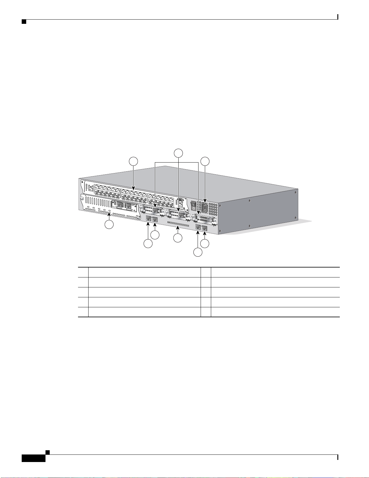
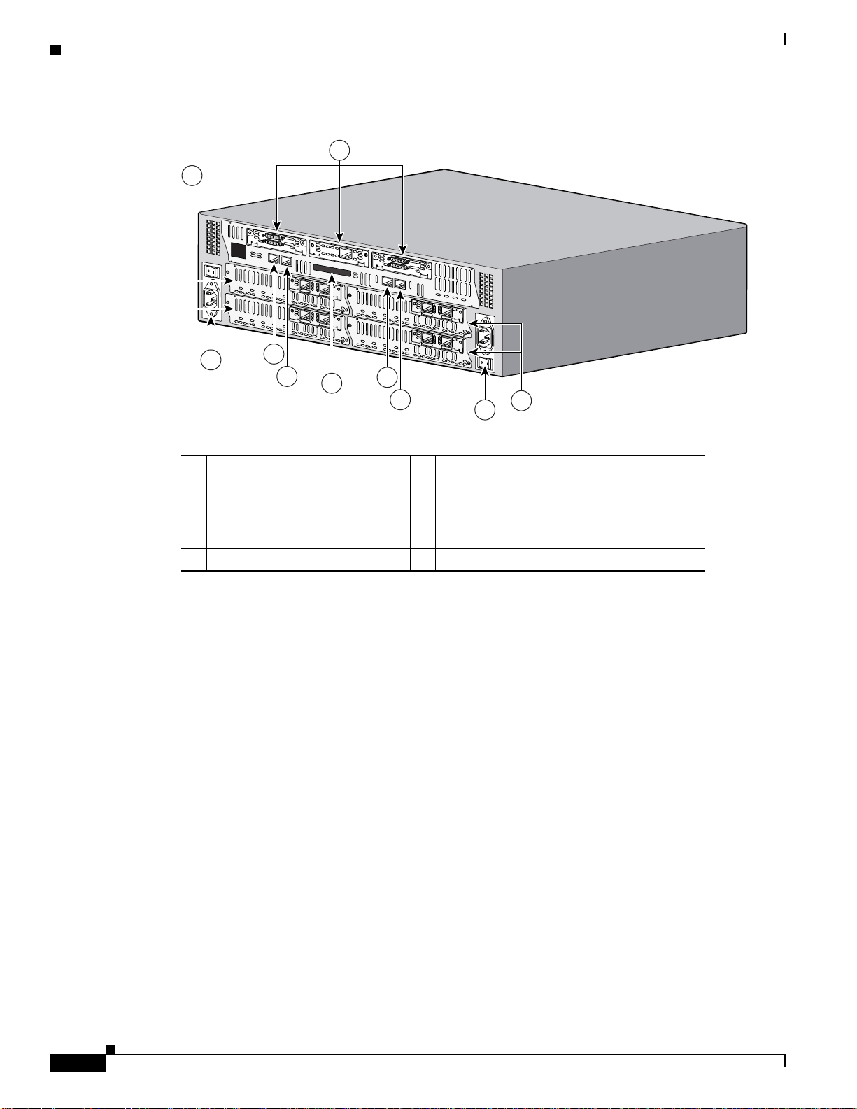
Figure 1-1 shows the rear panel of the Cisco 3725 router.
Figure 1-1 Rear Panel of the Cisco 3725 Router
2
1 3
Cisco 3745
NM-HDV
AL
BANK 4
BANK 3
VWIC
LP
2MFT-E1
BANK 2
BANK 1
BANK 0
9
SEE
MANUAL
CD
CTRLR E2
BEFORE
INSTALLATION
CTRLR E1
TD
RD
LP
AL
CD
SEE MANUAL BEFORE INSTALLATION
V0
EN
DSU
TD
56K
RD
LP
AL
CD
SEE MANUAL BEFORE INSTALLATION
DSU
56K
SEE MANUAL BEFORE INSTALLATION
7
8
6
4
62691
5
1 Double-wide network module slot 6 CompactFlash memory card slot
2 Interface card slots 7 Fast Ethernet 0/0 port
3 Power supply 8 Fast Ethernet 0/1 port
4 Auxiliary port 9 Single-wide network module slot
5 Console port
Cisco 3745 routers include the following additional features:
• High-performance 350-MHz RISC processor
• Up to 256 MB SDRAM
• Up to 128 MB CompactFlash memory
• Four slots for network modules that can accommodate up to two double-wide network modules
• Three interface card slots
• Two Cisco 3700 CompactFlash memory card slots (one external and one internal)
• Two AIM slots
1-2
Cisco 3700 Series Routers Hardware Installation Guide
OL-2180-08
Page 3
Chapter 1 Overview of Cisco 3700 Series Routers
• Installation in a 19- or 23-inch rack or on a desk
• Support for Cisco Redundant Power System
• 3-rack unit (RU) chassis height
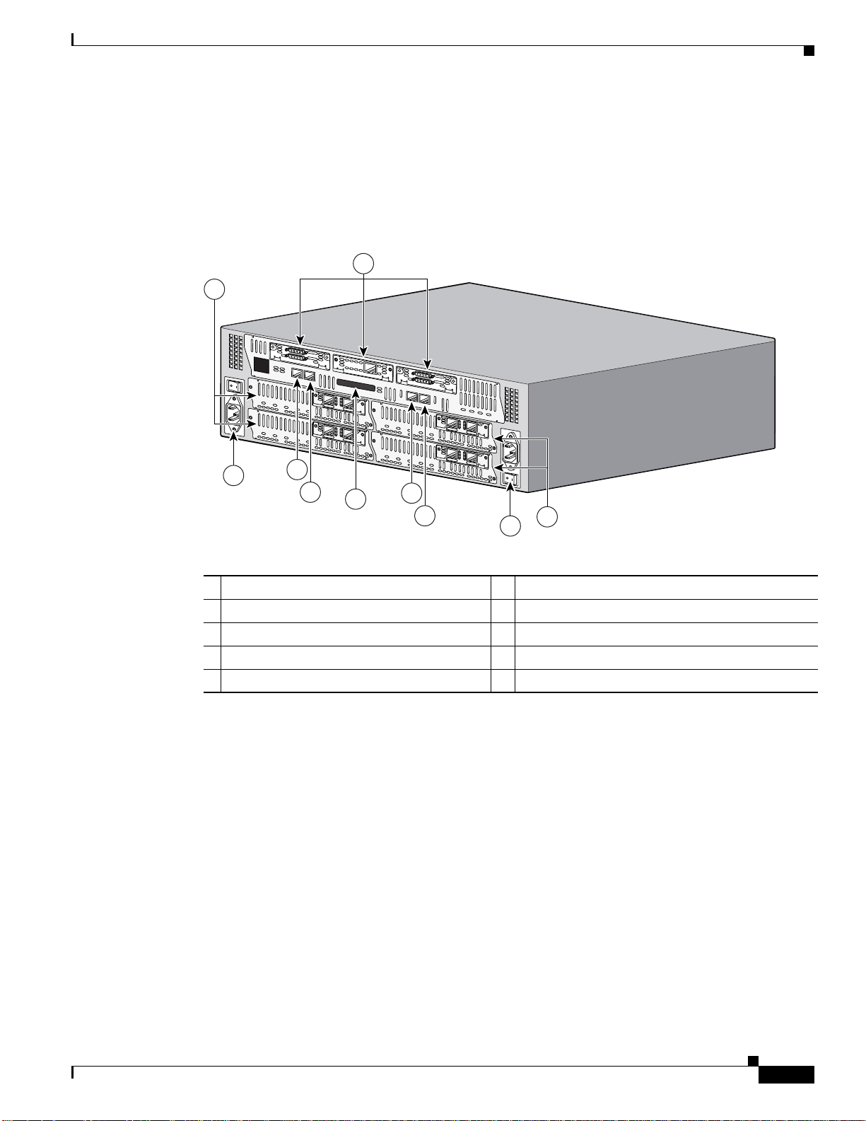
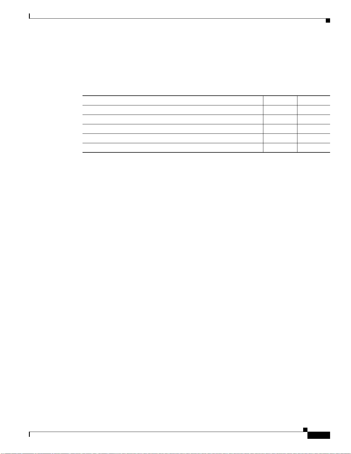
Figure 1-2 shows the rear panel of the Cisco 3745 router.
Figure 1-2 Rear Panel of the Cisco 3745 Router
10
CONN
SEE MANUAL BEFORE INSTALLATION
NM-HDV
BANK 4
BANK 3
BANK 2
BANK 1
NM-HDV
BANK 4
9
BANK 0
BANK 3
BANK 2
BANK 1
BANK 0
8
7
Modules, Interface Cards, and Memory
1
SERIAL 1
SERIAL 0
WIC
CONN
2T
TD
RD
LP
AL
SEE MANUAL BEFORE INSTALLATION
CD
DSU
56K
AL
VWIC
LP
2MFT-E1
SEE
NM-HDV
CD
MANUAL
CTRLR E2
BEFORE
INSTALLATION
CTRLR E1
V0
EN
AL
VWIC
LP
2MFT-E1
CD
CTRLR E2
BANK 4
SEE
NM-HDV
MANUAL
BEFORE
INSTALLATION
CTRLR E1
V0
EN
BANK 4
6
BANK 3
BANK 3
CONN
SEE MANUAL BEFORE INSTALLATION
BANK 2
BANK 1
BANK 2
BANK 1
5
SERIAL 1
SERIAL 0
WIC
CONN
2T
AL
VWIC
LP
2MFT-E1
SEE
CD
MANUAL
CTRLR E2
BEFORE
BANK 0
BANK 0
4
INSTALLATION
CTRLR E1
V0
EN
AL
VWIC
LP
2MFT-E1
SEE
CD
MANUAL
CTRLR E2
BEFORE
INSTALLATION
CTRLR E1
V0
EN
2
3
63390
1 Interface card slots 6 Cisco 3700 CompactFlash memory card slot
2 Network modules 7 Auxiliary port
3 Power supply 8 Console port
4 Fast Ethernet 0/0 port 9 Power supply
5 Fast Ethernet 0/1 port 10 Network modules
Modules, Interface Cards, and Memory
• For information on installing network modules, see the following documents:
• Quick Start Guide: Network Modules for Cisco 2600 Series, Cisco 3600 Series, and Cisco 3700
Series Routers
• Cisco Network Modules Hardware Installation Guide
For information on installing WICs and VICs, see the following documents:
• Quick Start Guide: Interface Cards for Cisco 1600, 1700, 2600, 3600, and 3700 Series
• Cisco Interface Cards Hardware Installation Guide
For information on installing AIMs, see the following documents:
• AIM Installation Quick Start Guide: Cisco 2600, Cisco 3600, and Cisco 3700 Series
• Installing Advanced Integration Modules in Cisco 2600 Series, Cisco 3600 Series, and Cisco 3700
Series Routers
OL-2180-08
Cisco 3700 Series Routers Hardware Installation Guide
1-3
Page 4
Memory
Memory
Chapter 1 Overview of Cisco 3700 Series Routers
For information on installing DRAM, SDRAM, NVRAM, and CompactFlash memory, see:
• Upgrading System Memory in Cisco 3700 Series Routers
• Installing Field-Replaceable Units in Cisco 3745 Routers
For information on installing CompactFlash memory cards, see:
• Installing and Formatting Cisco 2691, Cisco 3631, and Cisco 3700 CompactFlash Memory Cards
Cisco 3700 series routers support the following types of memory:
• SDRAM—Stores the running configuration and routing tables and is used for packet buffering by
the network interfaces. Cisco IOS software executes from SDRAM memory.
• NVRAM—Stores the system configuration file and virtual configuration register. For more
information, see Appendix C, “Configuration Register.” CompactFlash memory—Stores the
operating system software image. You can increase CompactFlash memory by adding Cisco 3700
CompactFlash memory cards. See the Installing and Formatting Cisco 3631 and Cisco 3700
CompactFlash Memory Cards document.
• EPROM-based memory—Stores the ROM monitor, which allows you to boot an operating system
software image from internal or external CompactFlash memory.
Table 1-1 and Table 1-2 list processor and memory specifications for Cisco 3700 series routers.
Table 1-1 Cisco 3725 Router Processor and Memory Specifications
Description Specification
Processor 240-MHz PMC-Sierra RM7061A RISC processor
SDRAM 128–256 MB
NVRAM 56 KB
CompactFlash 32, 64, or 128 MB
Boot ROM 512 KB
Table 1-2 Cisco 3745 Router Processor and Memory Specifications
Description Specification
Processor 350-MHz PMC-Sierra RM7000A RISC processor
SDRAM 128–256 MB
NVRAM 152 KB
CompactFlash 32, 64, or 128 MB
Boot ROM 704 KB
1-4
Cisco 3700 Series Routers Hardware Installation Guide
OL-2180-08
Page 5

Chapter 1 Overview of Cisco 3700 Series Routers
Interface Numbering
This section describes numbering conventions for interfaces on Cisco 3725 and Cisco 3745 routers.
Cisco 3725 Interfaces
Each individual interface (port) on a Cisco 3725 router is identified by number, as described in the
following sections.
WAN and LAN Interface Numbering
The Cisco 3725 router chassis contains the following WAN and LAN interface types:
• Two built-in Fast Ethernet LAN interfaces
• Three slots in which you can install WAN interface cards (WICs)
• One single-wide slot (slot 1) in which you can install one network module
• One double-wide slot (slot 2) in which you can install one single-wide or double-wide network
module
The numbering format is interface-type slot-number/interface-number. Two examples are:
• FastEthernet 0/0
• Serial 1/2
The slot numbers are as follows:
• 0 for all built-in interfaces
• 0 for all WIC interfaces
• 1 for interfaces in the single-wide network module slot
• 2 for interfaces in the double-wide network module slot
Interface (port) numbers begin at 0 for each interface type, and continue from right to left and (if
necessary) from bottom to top.
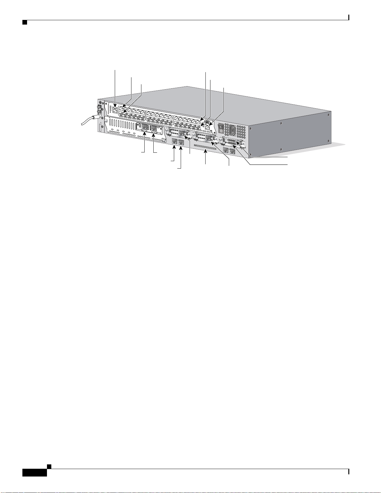
Figure 1-3 shows an example of interface numbering on a Cisco 3725 router with these interfaces:
• A WIC in each WIC slot (containing interfaces Serial 0/0 and Serial 0/1 in physical slot W0,
interface Serial 0/2 in physical slot W1, and interface BRI 0/0 in physical slot W2)
• A 2-port T1 network module in slot 1 (containing the following ports: T1 1/0 and T1 1/1)
• A 36-port EtherSwitch network module in slot 2 (containing the following ports: Fast Ethernet 2/0
through 2/35, and Gigabit Ethernet 2/0 and 2/1)
• Two built-in Ethernet 10/100-Mbps interfaces—Fast Ethernet 0/0 and Fast Ethernet 0/1
Interface Numbering
OL-2180-08
Cisco 3700 Series Routers Hardware Installation Guide
1-5
Page 6
Interface Numbering
Chapter 1 Overview of Cisco 3700 Series Routers
Figure 1-3 WAN and LAN Interface Numbering
Gigabit Ethernet 2/1
Fast Ethernet 2/35
Fast Ethernet 2/17
2
NM-HDV
BANK 4
BANK 3
1
VWIC
2MFT-E1
BANK 2
BANK 1
BANK 0
TI 1/1
Fast Ethernet 0/1
Fast Ethernet 0/0
AL
LP
SEE
MANUAL
CD
CTRLR E2
BEFORE
INSTALLATION
CTRLR E1
TD
RD
LP
AL
SEE MANUAL BEFORE INSTALLATION
V0
EN
TI 1/0
BRI 0/0
Fast Ethernet 2/18
Fast Ethernet 2/0
CD
DSU
TD
56K
RD
LP
AL
SEE MANUAL BEFORE INSTALLATION
Compact
Flash slot
Gigabit Ethernet 2/0
CD
DSU
56K
SEE MANUAL BEFORE INSTALLATION
Serial 0/2
56482
Serial 0/1
Serial 0/0
The slot number for all WIC interfaces is always 0. (The W0 and W1 slot designations are for physical
slot identificationonly.) Interfaces in the WICs are numbered from right to left, starting with 0/0 for each
interface type, regardless of which physical slot the WICs are installed in. Some examples are as follows:
• If slot W0 is empty and slot W1 contains a 1-port serial WIC, the serial interface in the WIC is
numbered Serial 0/0.
• If slot W0 contains a 2-port serial WIC and slot W1 contains a 1-port serial WIC, the serial
interfaces in physical slot W0 are numbered Serial 0/0 and Serial 0/1, and the serial interface in
physical slot W1 is numbered Serial 0/2.
• If slot W0 contains a 2-port serial WIC and slot W1 contains a 1-port BRI WIC, the serial interfaces
in physical slot W0 are numbered Serial 0/0 and Serial 0/1, and the BRI interface in physical slot
W1 is numbered BRI 0/0.
Voice Interface Numbering
Voice interfaces are numbered as follows:
chassis-slot/voice-module-slot/voice-interface
If a 4-channel voice network module is installed in chassis slot 1, the voice interfaces are:
• 1/0/0—Chassis slot 1/Voice module slot 0/Voice interface 0
• 1/0/1—Chassis slot 1/Voice module slot 0/Voice interface 1
• 1/1/0—Chassis slot 1/Voice module slot 1/Voice interface 0
• 1/1/1—Chassis slot 1/Voice module slot 1/Voice interface 1
Cisco 3700 Series Routers Hardware Installation Guide
1-6
OL-2180-08
Page 7

Chapter 1 Overview of Cisco 3700 Series Routers
Cisco 3745 Interfaces
Each individual interface (port) on a Cisco 3745 router is identified by number as described in the
following sections.
WAN and LAN Interface Numbering
The Cisco 3745 router chassis contains the following WAN and LAN interface types:
• Two built-in FastEthernet LAN interfaces
• Three slots in which you can install WAN or voice interface cards
• Four network module slots
The numbering format is interface-type slot-number/interface-number. Two examples are:
• FastEthernet 0/0
• Serial 1/2
The slot numbers are as follows:
• 0 for all built-in interfaces
• 0 for all WIC interfaces
• 1 for the lower-right network module slot
• 2 for the lower-left network module slot
• 3 for the upper-right network module slot
• 4 for the upper-left network module slot
If double-wide network modules are installed, the network module slots are numbered as follows:
• 2 for the lower double-wide slot
• 4 for the upper double-wide slot
Interface (port) numbers begin at 0 for each interface type, and continue from right to left and from
bottom to top.
Figure 1-4 shows the rear panel of the Cisco 3745 with:
• A WIC in each of the three WAN interface card slots
• A single-wide network module in each of the four network module slots
• Two AC power supplies
The slot number for all WIC interfaces is always 0. (The W0, W1, and W2 slot designations are for
physical slot identification only.) Interfaces in the WICs are numbered from right to left, starting with
0/0 for each interface type, regardless of which physical slot the WICs are installed in. Some examples
are:
If physical slot W0 is empty and physical slot W1 contains a 1-port serial WIC, the serial interface in
the WIC is numbered Serial 0/0.
If slot W0 contains a 2-port serial WIC and slot W1 contains a 1-port serial WIC, the serial interfaces in
physical slot W0 are numbered Serial 0/0 and Serial 0/1, and the serial interface in physical slot W1 is
numbered Serial 0/2.
If slot W0 contains a 2-port serial WIC and slot W1 contains a 1-port BRI WIC, the serial interfaces in
physical slot W0 are numbered Serial 0/0 and Serial 0/1, and the BRI interface in physical slot W1 is
numbered BRI 0/0.
Interface Numbering
OL-2180-08
Cisco 3700 Series Routers Hardware Installation Guide
1-7
Page 8
Interface Numbering
Figure 1-4 Cisco 3745 Rear Panel
1
10
SERIAL 1
CONN
SERIAL 0
SEE MANUAL BEFORE INSTALLATION
NM-HDV
BANK 4
BANK 3
BANK 2
NM-HDV
BANK 4
BANK 3
BANK 2
9
WIC
CONN
2T
TD
RD
LP
AL
SEE MANUAL BEFORE INSTALLATION
CD
DSU
56K
CONN
SEE MANUAL BEFORE INSTALLATION
AL
VWIC
LP
2MFT-E1
SEE
NM-HDV
CD
MANUAL
CTRLR E2
BANK 1
BANK 0
BANK 1
BANK 0
BEFORE
INSTALLATION
CTRLR E1
V0
EN
BANK 4
BANK 3
AL
VWIC
LP
2MFT-E1
SEE
CD
MANUAL
CTRLR E2
BEFORE
INSTALLATION
CTRLR E1
V0
BANK 2
NM-HDV
EN
BANK 1
BANK 4
BANK 3
BANK 2
BANK 1
8
7
6
5
4
Chapter 1 Overview of Cisco 3700 Series Routers
SERIAL 1
SERIAL 0
WIC
CONN
2T
AL
VWIC
LP
2MFT-E1
SEE
CD
MANUAL
CTRLR E2
BEFORE
BANK 0
BANK 0
INSTALLATION
CTRLR E1
V0
EN
AL
VWIC
LP
2MFT-E1
SEE
CD
MANUAL
CTRLR E2
BEFORE
INSTALLATION
CTRLR E1
V0
EN
2
3
63390
1 Interface card slots 6 Cisco 3700 CompactFlash memory card slot
2 Network modules 7 Auxiliary port
3 Power supply 8 Console port
4 Fast Ethernet 0/0 port 9 Power supply
5 Fast Ethernet 0/1port 10 Network modules
Voice Interface Numbering
Voice interfaces are numbered differently from the WAN interfaces described in the previous section.
Voice interfaces are numbered as follows:
network-module-slot/voice-module-slot/voice-interface
If a 4-channel voice network module is installed in chassis slot 1, the voice interfaces are:
• 1/0/0—Network module slot 1/Voice module slot 0/Voice interface 0
• 1/0/1—Network module slot 1/Voice module slot 0/Voice interface 1
• 1/1/0—Network module slot 1/Voice module slot 1/Voice interface 0
• 1/1/1—Network module slot 1/Voice module slot 1/Voice interface 1
1-8
Cisco 3700 Series Routers Hardware Installation Guide
OL-2180-08
Page 9
Chapter 1 Overview of Cisco 3700 Series Routers
Power Supply Options
Table 1-3 lists the power supply options supported by Cisco 3700 series routers. Depending on the
configuration specified when you placed your order, your router may not support all of these options.
Table 1-3 Power Supply Options for Cisco 3700 Series Routers
Power Supply Option Cisco 3725 Cisco 3745
AC input power Yes Yes
DC input power Yes Yes
–48-V telephony power module to provide inline power to IP phones Yes Yes
Dual hot-swappable power supplies No Yes
Compatible with Cisco Redundant Power System Yes Yes
1. Because of increased power consumption in high-temperature environments, a fully loaded Cisco 3745 router requires both
power supplies when ambienttemperatureexceeds 104˚F (40˚C). Cisco 3745 routers operating under these conditions do not
support the online replacement of power supplies.
Power Supply Options
1
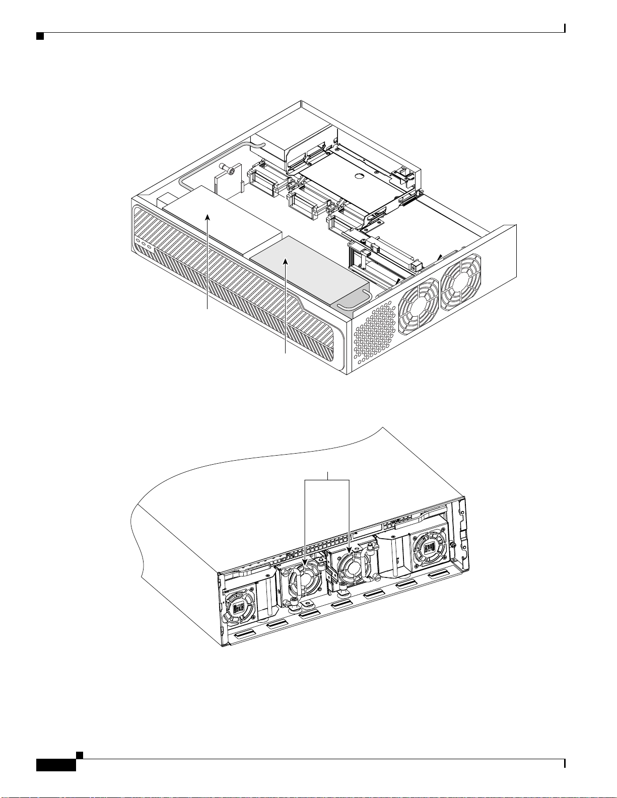
Internal –48 V Telephony Power Modules
Cisco 3700 series routers provide inline power to IP phones connected to the router through Ethernet
switch network modules. This power is supplied by special –48 V modules that connect directly to the
chassis power supplies in Cisco 3725 and Cisco 3745 routers. A single –48 V power module meets the
power needs of up to 36 IP phones. A Cisco 3745 router with two –48 V power modules installed
provides redundant power for up to 36 IP phones. Figure 1-5 and Figure 1-6 show the –48 -V power
modules as they appear when installed in Cisco 3700 series routers.
OL-2180-08
Cisco 3700 Series Routers Hardware Installation Guide
1-9
Page 10
Power Supply Options
Chapter 1 Overview of Cisco 3700 Series Routers
Figure 1-5 Cisco 3725 Router with Optional –48 V Power Module Installed
72086
AC
power module
-
48V
power module
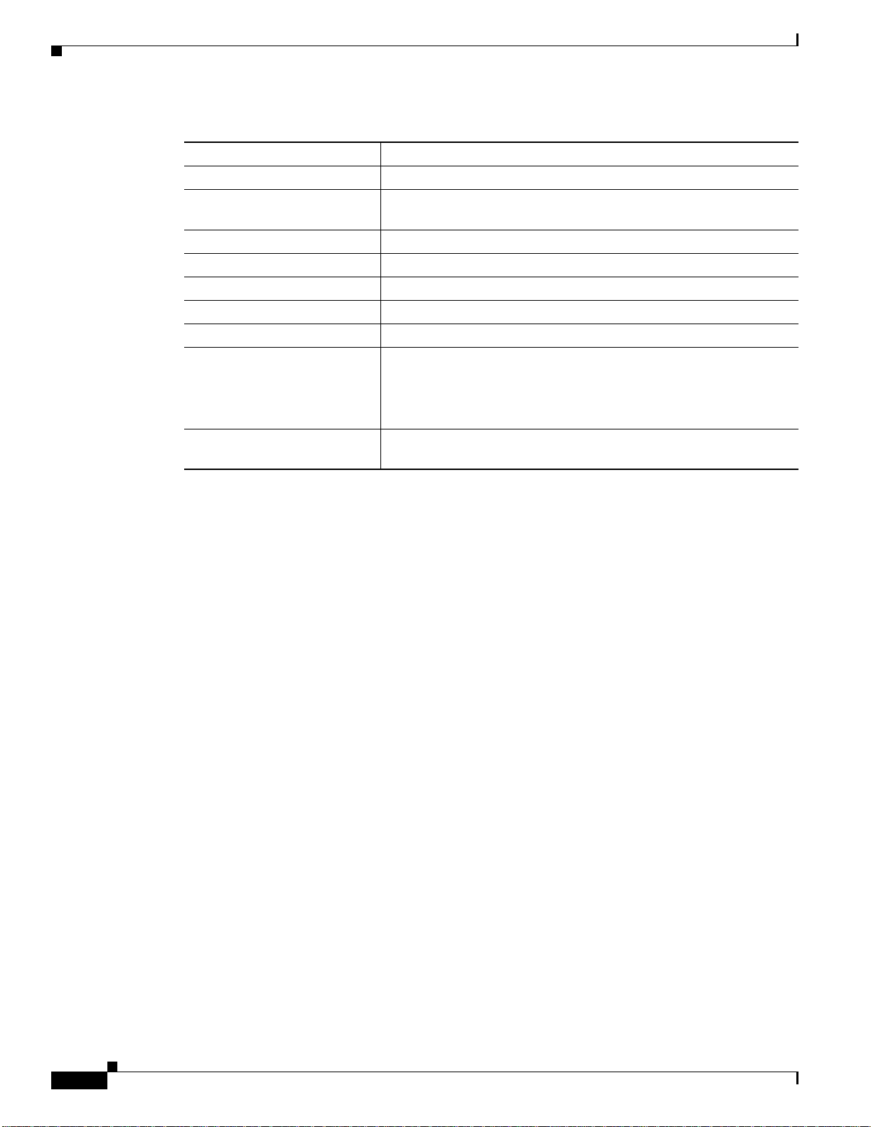
Figure 1-6 Cisco 3745 Router with Optional –48 V Power Modules Installed
-
48V power modules
72085
1-10
Cisco 3700 Series Routers Hardware Installation Guide
OL-2180-08
Page 11

Chapter 1 Overview of Cisco 3700 Series Routers
System Specifications
Table 1-4 and Table 1-5 list Cisco 3700 series system specifications.
Table 1-4 Cisco 3725 Router System Specifications
Description Specification
Dimensions (H x W x D) 3.5 x 17.1 x 15.0 in. (8.9 x 43.4 x 38.1 cm), 2-RU chassis height
Weight 14 lb (6.4 kg)
Input voltage, AC power supply
Frequency
Input surge current (AC)
Input rating, DC power supply
Input surge current (DC)
Power dissipation 135 W (maximum)
Heat Dissipation 135W Maximum 460.661 BTU/hour, 495W Maximum 1689.089
Console and auxiliary ports RJ-45 connector
Operating humidity 5–95%, noncondensing
Operating temperature 32–104°F (0–40°C)
Nonoperating temperature –40 to 162°F (–40 to 72°C)
Noise level 52 dBA (maximum)
Regulatory compliance FCC Part 15 Class A.
Safety compliance UL 60950; CAN/CSA C22.2 No. 60950-00; IEC 60950;
System Specifications
100 to 240 VAC, autoranging
47–63 Hz
50 A maximum, one cycle (–48-V power module included)
24–36 VDC, 9 A, positive or negative,operational from 18–36 VDC
36–60 VDC, 4 A, positive or negative,operational from 36–72 VDC
50 A, < 10 ms
BTU/hour
For additional compliance information, see the Cisco 2600 Series,
Cisco 3600 Series, and Cisco 3700 Series Regulatory Compliance
and Safety Information document that accompanied the router.
AS/NZS 3260; TS001
OL-2180-08
Table 1-5 Cisco 3745 Router System Specifications
Description Specification
Dimensions (H x W x D) 5.25 x 17.25 x 15.00 in. (13.3 x 43.8 x 38.1 cm), 3-RU chassis height
Weight 32 lb (14.5 kg), including chassis and four network modules
Input voltage, AC power
supply
Frequency
Input surge current (AC)
Input rating, DC power supply
Operational between
Input surge current (DC)
100–240 VAC, autoranging
47–63 Hz
80 A maximum, one cycle (–48-V power module included)
–48 to –60 VDC, 10 A maximum
–38 to –75 VDC, 10 A maximum
50 A, < 10 ms
Cisco 3700 Series Routers Hardware Installation Guide
1-11
Page 12
Regulatory Compliance
Chapter 1 Overview of Cisco 3700 Series Routers
Table 1-5 Cisco 3745 Router System Specifications (continued)
Description Specification
Power dissipation 230 W (maximum)
Heat Dissipation 230W Maximum 784.829 BTU/hour, 590W Maximum 2013.257
BTU/hour
Console and auxiliary ports RJ-45 connector
Operating humidity 5–95%, noncondensing
Operating temperature 32–104°F (0–40°C)
1
Nonoperating temperature –40 to 162°F (–40 to 72°C)
Noise level 60 dBA (maximum)
Regulatory compliance FCC Part 15 Class A.
For additional compliance information, see the Cisco 2600 Series,
Cisco 3600 Series, and Cisco 3700 Series Regulatory Compliance
and Safety Information document that accompanied the router.
Safety compliance UL 60950; CAN/CSA C22.2 No. 60950-00; IEC 60950;
AS/NZS 3260; TS001
1. Because of increased power consumption in high-temperature environments, a fully loaded Cisco 3745 router requires both
power supplies when ambient temperature exceeds 104˚F (40˚C).
Regulatory Compliance
For compliance information, see the Cisco 2600 Series, Cisco 3600 Series, and Cisco 3700 Series
Regulatory Compliance and Safety Information document that accompanied the router.
1-12
Cisco 3700 Series Routers Hardware Installation Guide
OL-2180-08
 Loading...