

Page 1
CHAPTER
Installation on Cisco 3660 Routers
This chapter describes how to install a NEBS Level 3/ETSI kit on your Cisco 3660 router and contains
the following sections:
• Attaching the 23-Inch Rack-Mounting Brackets, page 4-1
• Installing the Ground Lug, page 4-4
• Making Network Connections, page 4-6
• Installing the Alarm Terminal Block, page 4-7
Note If you have yet to install your Cisco 3600 series router, see the publication Cisco 3600 Series
Hardware Installation Guide.
You can access this document
your router
Access Routers > Cisco 3600 Series Routers > Hardware installation documents for Cisco 3600
series
at: Cisco Product Documentation > Access Servers and Access Routers > Modular
online and on the documentation CD-ROM that you received with
4
Attaching the 23-Inch Rack-Mounting Brackets
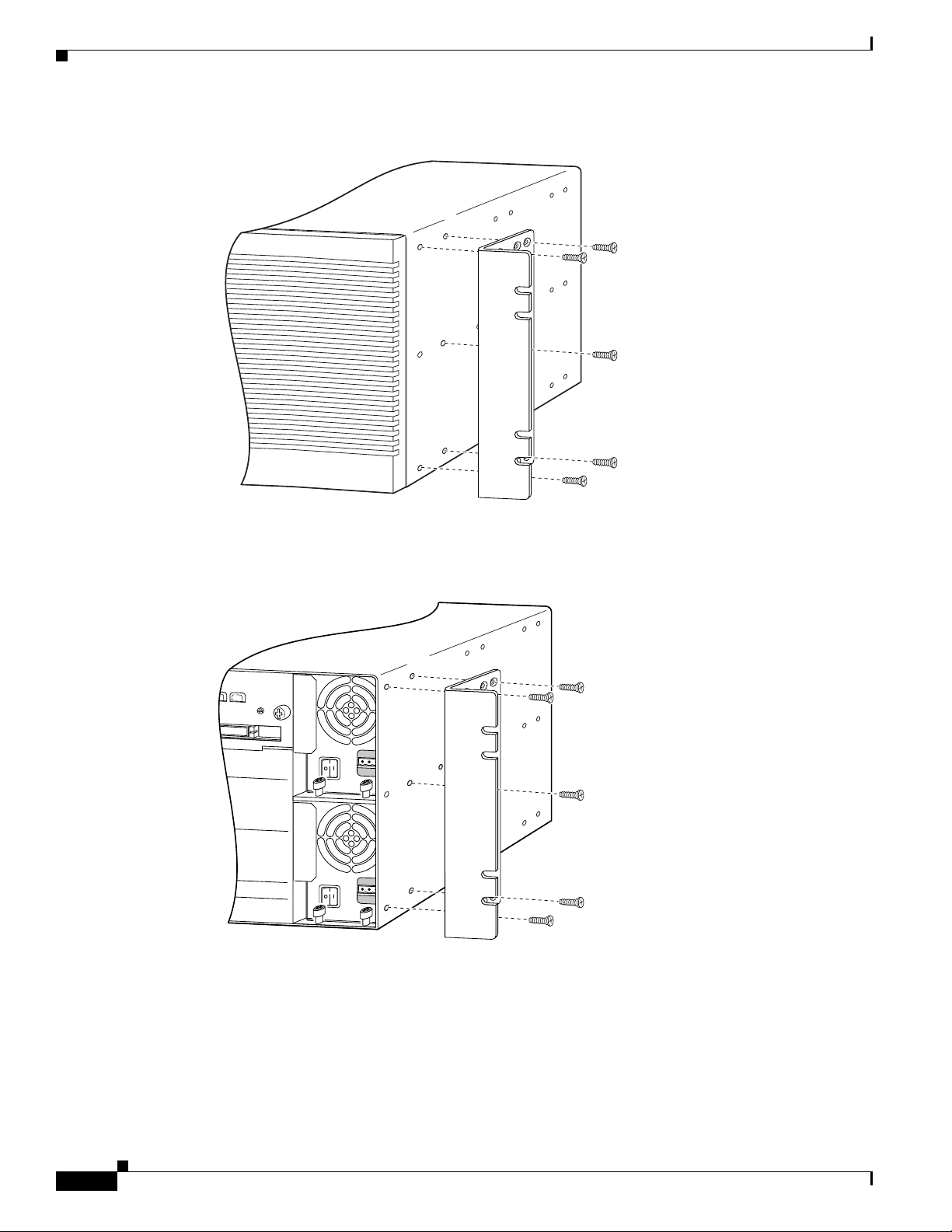
The NEBS kit for Cisco 3660 routers comes with rack-mount brackets for installing the Cisco 3600
series routers in 23-inch or 24-inch racks.
Attach the mounting brackets to the chassis as shown in Figure 4-1, Figure 4-2, or Figure 4-3, using the
screws provided. Attach the second bracket to the opposite side of the chassis.
NEBS Level 3 and ETSI Compliance Kit Installation Guide for Cisco 3620, Cisco 3640, and Cisco 3660 Routers
78-5450-06 B0
4-1
Page 2
Attaching the 23-Inch Rack-Mounting Brackets
Figure 4-1 23-Inch Bracket Attachment to Cisco 3660 Chassis—Front Panel Forward
Chapter 4 Installation on Cisco 3660 Routers
Note: The second bracket attaches to the other side of the chassis.
26322
Figure 4-2 23-Inch Bracket Attachment to Cisco 3660 Chassis—Rear Panel Forward
17330
Note: The second bracket attaches to the other side of the chassis.
4-2
NEBS Level 3 and ETSI Compliance Kit Installation Guide for Cisco 3620, Cisco 3640, and Cisco 3660 Routers
78-5450-06 B0
Page 3
Chapter 4 Installation on Cisco 3660 Routers
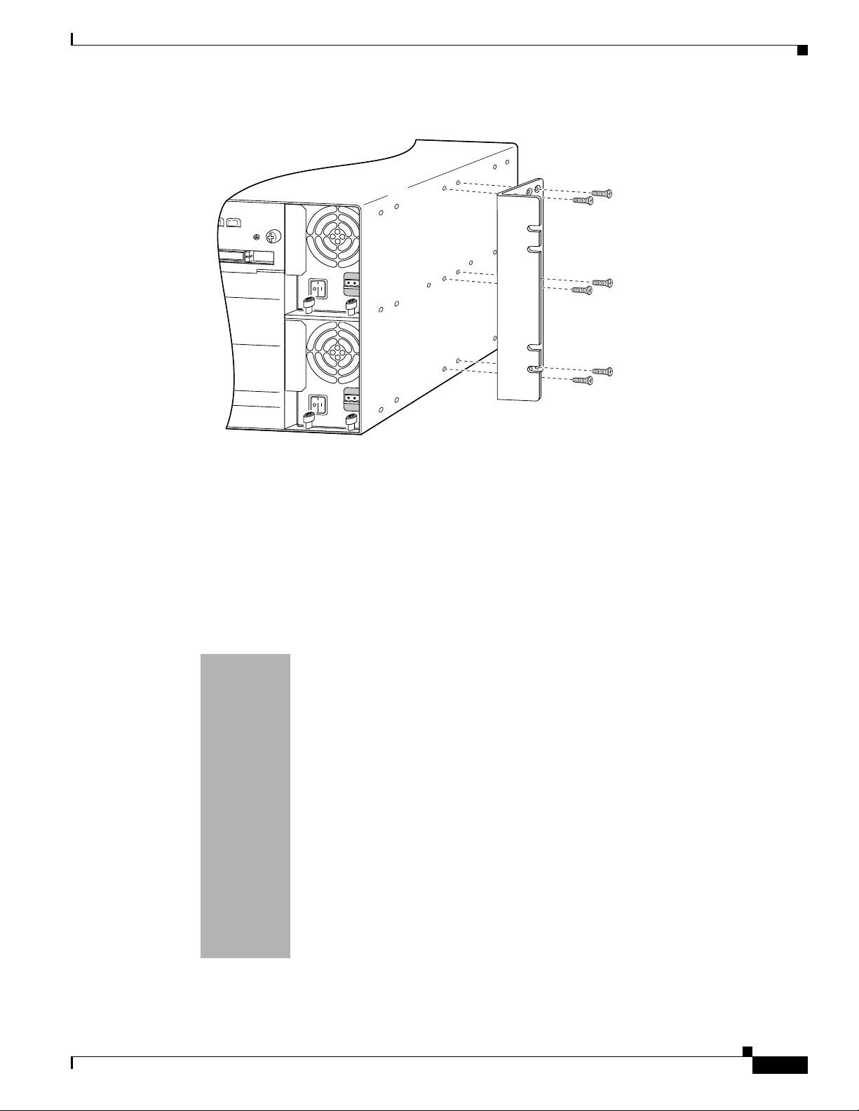
Figure 4-3 23-Inch Bracket Attachment to Cisco 3660 Chassis—Center-Mount, Rear Panel Forward
Installing the Cable Management Bracket
Note: The second bracket attaches to the other side of the chassis.
The brackets can also be installed with the front panel forward.
Installing the Cable Management Bracket
The NEBS kit for Cisco 3660 routers comes with a cable management bracket for managing cables for
the Cisco 3600 series router. (See Figure 4-4.)
Figure 4-4 Cable Management Bracket to Cisco 3660 Chassis
22657
78-5450-06 B0
Attach the cable management bracket to the chassis as shown in Figure 4-5, using the screws provided.
Wrap cables to the management bracket as shown in Figure 4-6.
NEBS Level 3 and ETSI Compliance Kit Installation Guide for Cisco 3620, Cisco 3640, and Cisco 3660 Routers
4-3
Page 4

Installing the Ground Lug
Chapter 4 Installation on Cisco 3660 Routers
Figure 4-5 Cable Management Bracket on the Cisco 3660 Chassis
X
FD
V0
EN
N
E
HIGH SPEED SERIAL
1HSSI
ETHERNET
4E
LINK
s
bp
M
100
ETH 2
ETH 3
X
FD
K
IN
L
bps
M
C
X
R
P
/L
IN USE
1
SEE MANUAL BEFORE INSTALLATION
L 1
IA
ER
S
X
T
C
X
T
D
X
R
100
IN USE
0
0
L
IA
ER
S
D
X
T
C
X
DT
X
R
C
X
R
P
L
/
N
C
D
C OK
VC
EM
SYST
VOICE
2V
V1
L
IA
ER
S
4T
IAL 3
R
SE
D
X
T
C
X
T
D
X
R
C
X
R
P
/L
N
C
VIC
FXS
L 2
IA
ER
S
N
C
D
X
T
C
X
T
D
X
R
C
X
R
P
/L
N
C
1
0
HSSI 0
TD
TC
RD
RC
LB/CN
ETH 1
0
1
2
3
K
IN
L
T
C
A
N
E
ETH 0
EN
Figure 4-6 Wrapping Cables to the Management Bracket on the Cisco 3660 Chassis
72339
Installing the Ground Lug
Follow this procedure to attach the ground lug to your router chassis:
Step 1 Turn OFF power to the router. However, to channel ESD voltages to ground, do not unplug the power
cable. Remove all network interface cables, including telephone cables, from the rear panel.
The following warning applies to routers that use a DC power supply:
NEBS Level 3 and ETSI Compliance Kit Installation Guide for Cisco 3620, Cisco 3640, and Cisco 3660 Routers
4-4
78-5450-06 B0
Page 5

Chapter 4 Installation on Cisco 3660 Routers
Installing the Ground Lug
Warning
Before performing any of the following procedures, ensure that power is removed from the DC
circuit. To ensure that all power is OFF, locate the circuit breaker on the panel board that services
the DC circuit, switch the circuit breaker to the OFF position, and tape the switch handle of the
circuit breaker in the OFF position. To see translations of the warnings that appear in this
publication, refer to the Regulatory Compliance and Safety Information document that
accompanied this device.
Step 2 Strip one end of the 6-AWG wire to expose approximately 0.75 in. (20 mm).
Step 3 Crimp the ground lug around the wire. (See Figure 4-7.)
Figure 4-7 Crimping the Lug Around the Wire
Step 4
10360
Use the number 2 Phillips screwdriver to fasten the ground lug to the Cisco 3660 router chassis. (See
Figure 4-8.)
78-5450-06 B0
NEBS Level 3 and ETSI Compliance Kit Installation Guide for Cisco 3620, Cisco 3640, and Cisco 3660 Routers
4-5
Page 6

Making Network Connections
ETH 0
ETH 3
ET
H
ER
N
E
T
4E
ETH 2
ETH 1
12
3
ACT
LINK
0
C
N/LP
RXC
SERIAL 3
SERIAL 2
SERIAL 1 SERIAL 0
RXD
TXC
TXD
CN
/LP
RXC
RXD
TXC
TXD
CN/LP RXC
RXD
TXC
TXD
CN/LP RXC
RXD
TXC
TXD
EN
S
ERIA
L
4T
VOICE
2V
V0
V1
EN
HIGH SPEED SERIAL
1HSSI
H
TD
TC
RD
RC
LB/CN
Figure 4-8 Ground Lug Fastened to Cisco 3660 Chassis
V
C
C
O
S
Y
S
T
E
Chapter 4 Installation on Cisco 3660 Routers
K
M
F
D
X
LIN
K
10
0
M
b
ps
V
IC
F
X
S
F
D
X
L
IN
K
10
0
M
b
p
s
IN USE
1
IN USE
S
E
E
M
A
N
0
U
A
L
B
E
F
O
R
E
I
N
S
T
A
L
L
A
T
IO
N
1
0
22659
Ground lug
Step 5 Connect the other end of the ground lug wire to a grounding point at your site.
Making Network Connections
Note If you still need to install network modules or WAN interface cards, you can do so now. For
instructions, see these publications: Cisco 3600 Series Hardware Installation Guide, Cisco Network
Modules Hardware Installation Guide, Cisco WAN Interface Cards Hardware Installation Guide.
You can access these documents
your router
at: Cisco Product Documentation > Access Servers and Access Routers > Modular
Access Routers > Cisco 3600 Series Routers > Hardware installation documents for Cisco 3600
series
Reinstall network cables and turn ON power to the router.
Note The shielded cables in your NEBS/ETSI kit replace the cables originally shipped with your router.
online and on the documentation CD-ROM that you received with
Caution NEBS/ETSI Intrabuilding Lightning Requirement
This equipment is suitable for connection to intrabuilding or nonexposed wiring or cabling only. This
cabling must be shielded.
4-6
NEBS Level 3 and ETSI Compliance Kit Installation Guide for Cisco 3620, Cisco 3640, and Cisco 3660 Routers
78-5450-06 B0
Page 7

Chapter 4 Installation on Cisco 3660 Routers
ETH 0
ETH 3
E
T
H
E
R
N
E
T
4E
ETH 2
ETH 1
12
3
ACT
LINK
0
CN/LP
RXC
SERIAL 3
SERIAL 2
SERIAL 1 SERIAL 0
RXD
TXC
TXD
CN/LP
RXC
RXD
TXC
TXD
CN/LP RXC
RXD
TXC
TXD
CN/LP RXC
RXD
TXC
TXD
EN
S
E
RIA
L
4T
VO
IC
E
2V
V0
V1
EN
HIGH SPEED SERIAL
1HSSI
H
TD
TC
RD
RC
LB/CN
The following warning applies to routers that use a DC power supply:
Installing the Alarm Terminal Block
Warning
After wiring the DC power supply, remove the tape from the circuit breaker switch handle and
reinstate power by moving the handle of the circuit breaker to the ON position. To see translations
of the warnings that appear in this publication, refer to the Regulatory Compliance and Safety
Information document that accompanied this device.
Installing the Alarm Terminal Block
The alarm port on the Cisco 3660 rear panel (see Figure 4-9) provides relay outputs to connect the router
to a remote alarm.
Figure 4-9 Alarm Port on the Cisco 3660 Router
V
C
C
O
K
S
Y
S
T
E
M
F
D
X
L
IN
K
1
0
0
M
b
p
s
NO
P
NC
F
D
X
L
IN
K
1
0
0
M
b
p
s
1
0
V
IC
IN USE
F
X
Alarm port
Slot 6
Slot 4
Slot 2
S
1
IN USE
S
E
E
M
A
N
0
U
A
L
B
E
F
O
R
E
IN
S
T
A
L
L
A
T
IO
N
Slot 0
Slot 5
Slot 3
Slot 1
The terminals are described in Table 4-1. In order to operate the alarm port, wire the P terminal and one
of the other terminals (NO and NC).
Ta b le 4 - 1 A l arm Te r m i na l B l o c k C o n n e c t i o n s
Terminal Meaning
P Primary—This pin is connected to the common contact of the alarm relay.
NO Normally open—This pin is connected to the “normally open” contact of the alarm
relay, and is disconnected from the primary pin during normal system operation.
During an alarm condition it is connected to the primary pin by the alarm relay.
NC Normally closed—This pin is connected to the “normally closed” contact of the
alarm relay, and is connected to the primary pin during normal system operation.
During an alarm condition it is disconnected from the primary pin by the alarm relay.
22660
78-5450-06 B0
NEBS Level 3 and ETSI Compliance Kit Installation Guide for Cisco 3620, Cisco 3640, and Cisco 3660 Routers
4-7
Page 8

Installing the Alarm Terminal Block
Follow this procedure to install the alarm terminal block (see Figure 4-10) in the Cisco 3660 router alarm
port:
Step 1 Turn OFF power to the router. However, to channel ESD voltages to ground, do not unplug the power
cable.
Step 2 Use 12- or 14-AWG copper wires to connect DC-input power to the terminal blocks.
Step 3 Strip the wire shielding so that approximately 0.38 in. (9.7 mm) of each wire is exposed.
Figure 4-10 Alarm Terminal Block
Chapter 4 Installation on Cisco 3660 Routers
22661
Step 4
NO P NC
Press the orange-colored release and insert a wire into a receptacle of the alarm terminal block. Two of
the three receptacles must have wires installed (see Table 4-1). The spring-loaded connector retains the
wires.
Note Always wire the P terminal and one of the other (NO and NC) terminals.
Note To remove wires, press the orange-colored release next to each receptacle.
Step 5 Plug the alarm terminal block into the alarm port on the Cisco 3660 chassis. (See Figure 4-11.)
Note Connect the alarm terminal block to either an AC power source rated maximum 25 VAC and
5A current rating, or a DC power source rated maximum 30V and 5A current rating.
Figure 4-11 Connecting the Alarm Terminal Block to the Alarm Port
4-8
V
C
C
O
K
S
Y
S
T
E
M
F
D
X
L
IN
K
1
0
0
M
b
p
s
F
D
X
L
IN
K
1
0
0
M
b
p
s
1
0
22861
Step 6
Reinstall network cables, and turn ON power to the router.
NEBS Level 3 and ETSI Compliance Kit Installation Guide for Cisco 3620, Cisco 3640, and Cisco 3660 Routers
78-5450-06 B0
 Loading...