

Page 1

Preface
Purpose
This guide describes the hardware features of the Catalyst 3650 switches. It describes the physical and
performance characteristics of each switch, explains how to install a switch, and provides
troubleshooting information.
This guide does not describe system messages that you might receive or how to configure your switch.
See the switch software configuration guide, the switch command reference, and the switch system
message guide on
http://www.cisco.com/go/cat3650_docs
Document Conventions
This document uses the following conventions.
Note Means reader take note. Notes contain helpful suggestions or references to materials not contained in
this manual.
OL-29734-01
Caution Means reader be careful. In this situation, you might do something that could result in equipment
damage or loss of data.
Catalyst 3650 Switch Hardware Installation Guide
v
Page 2

Preface
Warning
IMPORTANT SAFETY INSTRUCTIONS
This warning symbol means danger. You are in a situation that could cause bodily injury. Before you
work on any equipment, be aware of the hazards involved with electrical circuitry and be familiar
with standard practices for preventing accidents. Use the statement number provided at the end of
each warning to locate its translation in the translated safety warnings that accompanied this
device.
SAVE THESE INSTRUCTIONS
The safety warnings for this product are translated into several languages in the Regulatory Compliance
and Safety Information for the Catalyst 3650 Switch that is available on Cisco.com. The EMC regulatory
statements are also included in that guide.
Statement 1071
Related Documentation
Note Before installing or upgrading the switch, refer to the switch release notes.
• Catalyst 3650 switch documentation at:
http://www.cisco.com/go/cat3650_docs
• Cisco SFP and SFP+ modules documentation, including compatibility matrixes at:
http://www.cisco.com/en/US/products/hw/modules/ps5455/tsd_products_support_series_home.ht
ml
• Cisco Validated Designs documents at:
http://www.cisco.com/go/designzone
• Error Message Decoder, located at:
https://www.cisco.com/cgi-bin/Support/Errordecoder/index.cgi
Obtaining Documentation and Submitting a Service Request
For information on obtaining documentation, submitting a service request, and gathering additional
information, see the monthly What’s New in Cisco Product Documentation, which also lists all new and
revised Cisco technical documentation, at:
http://www.cisco.com/en/US/docs/general/whatsnew/whatsnew.html
Subscribe to the What’s New in Cisco Product Documentation as a Really Simple Syndication (RSS) feed
and set content to be delivered directly to your desktop using a reader application. The RSS feeds are a free
service and Cisco currently supports RSS Version 2.0.
vi
Catalyst 3650 Switch Hardware Installation Guide
OL-29734-01
Page 3

Product Overview
The Catalyst 3650 series switches are Ethernet switches to which you can connect devices such as
Cisco IP Phones, Cisco Wireless Access Points, workstations, and other network devices such as servers,
routers, and other switches.
The Catalyst 3650 switches support stacking through Cisco StackWise-160 technology.
Unless otherwise noted, the term switch refers to a standalone switch and to a switch stack.
• Switch Models, page 1-1
• Front Panel, page 1-4
• Rear Panel, page 1-15
• Management Options, page 1-20
Switch Models
CHA P T E R
1
Table 1-1 Catalyst 3650 Switch Models
Switch Model Cisco IOS Image Description
Catalyst 3650-24TS-L LAN Base Stackable 24 10/100/1000 Ethernet downlink
ports, 4 1-Gigabit SFP (small form-factor
pluggable) uplink ports, 250-W power supply
Catalyst 3650-48TS-L LAN Base Stackable 48 10/100/1000 Ethernet downlink
ports, 4 1-Gigabit SFP uplink ports, 250-W power
supply
Catalyst 3650-24PS-L LAN Base Stackable 24 10/100/1000 PoE+
4 1-Gigabit SFP uplink ports, 640-W power
supply
Catalyst 3650-48PS-L LAN Base Stackable 48 10/100/1000 PoE+ downlink ports,
4 1-Gigabit SFP uplink ports, 640-W power
supply
Catalyst 3650-48FS-L LAN Base Stackable 48 10/100/1000 Full POE downlink
ports, 4 1-Gigabit SFP uplink ports, 1025-W
power supply
1
downlink ports,
OL-29734-01
Catalyst 3650 Switch Hardware Installation Guide
1-1
Page 4

Switch Models
Chapter 1 Product Overview
Table 1-1 Catalyst 3650 Switch Models (continued)
Switch Model Cisco IOS Image Description
Catalyst 3650-24TD-L LAN Base Stackable 24 10/100/1000 Ethernet downlink
ports, 2 1-Gigabit SFP and 2 10-Gigabit SFP+
uplink ports, 250-W power supply
Catalyst 3650-48TD-L LAN Base Stackable 48 10/100/1000 Ethernet downlink
ports, 2 1-Gigabit SFP and 2 10-Gigabit SFP+
uplink ports, 250-W power supply
Catalyst 3650-24PD-L LAN Base Stackable 24 10/100/1000 PoE+ downlink ports,
2 1-Gigabit SFP and 2 10-Gigabit SFP+ uplink
ports, 640-W power supply
Catalyst 3650-48PD-L LAN Base Stackable 48 10/100/1000 PoE+ downlink ports,
2 1-Gigabit SFP and 2 10-Gigabit SFP+ uplink
ports, 640-W power supply
Catalyst 3650-48FD-L LAN Base Stackable 48 10/100/1000 Full PoE downlink
ports, 2 1-Gigabit SFP and 2 10-Gigabit SFP+
uplink ports, 1025-W power supply
Catalyst 3650-48FQ-L LAN Base Stackable 48 10/100/1000 Full PoE downlink
ports, 4 10-Gigabit SFP+ uplink ports, 1025-W
power supply
Catalyst 3650-48PQ-L LAN Base Stackable 48 10/100/1000 PoE+ downlink ports,
4 10-Gigabit SFP+ uplink ports, 640-W power
supply
Catalyst 3650-48TQ-L LAN Base Stackable 48 10/100/1000 Ethernet downlink
ports, 4 10-Gigabit SFP+ uplink ports, 250-W
power supply
Catalyst 3650-24TS-S IP Base Stackable 24 10/100/1000 Ethernet downlink
ports, 4 1-Gigabit SFP uplink ports, 250-W power
supply
Catalyst 3650-48TS-S IP Base Stackable 48 10/100/1000 Ethernet downlink
ports, 4 1-Gigabit SFP uplink ports, 250-W power
supply
Catalyst 3650-24PS-S IP Base Stackable 24 10/100/1000 PoE+ downlink ports,
4 1-Gigabit SFP uplink ports, 640-W power
supply
Catalyst 3650-48PS-S IP Base Stackable 48 10/100/1000 PoE+ downlink ports,
4 1-Gigabit SFP uplink ports, 640-W power
supply
Catalyst 3650-48FS-S IP Base Stackable 48 10/100/1000 Full PoE downlink
ports, 4 1-Gigabit SFP uplink ports, 1025-W
power supply
Catalyst 3650-24TD-S IP Base Stackable 24 10/100/1000 Ethernet downlink
ports, 2 1-Gigabit SFP and 2 10-Gigabit SFP+
uplink ports, 250-W power supply
1-2
Catalyst 3650 Switch Hardware Installation Guide
OL-29734-01
Page 5

Chapter 1 Product Overview
Table 1-1 Catalyst 3650 Switch Models (continued)
Switch Model Cisco IOS Image Description
Catalyst 3650-48TD-S IP Base Stackable 48 10/100/1000 Ethernet downlink
Catalyst 3650-24PD-S IP Base Stackable 24 10/100/1000 PoE+ downlink ports,
Catalyst 3650-48PD-S IP Base Stackable 48 10/100/1000 PoE+ downlink ports,
Catalyst 3650-48FD-S IP Base Stackable 48 10/100/1000 Full PoE downlink
Catalyst 3650-48FQ-S IP Base Stackable 48 10/100/1000 Full PoE downlink
Catalyst 3650-48PQ-S IP Base Stackable 48 10/100/1000 PoE+ downlink ports,
Catalyst 3650-48TQ-S IP Base Stackable 48 10/100/1000 Ethernet downlink
Catalyst 3650-24TS-E IP Services Stackable 24 10/100/1000 Ethernet downlink
Catalyst 3650-48TS-E IP Services Stackable 48 10/100/1000 Ethernet downlink
Catalyst 3650-24PS-E IP Services Stackable 24 10/100/1000 PoE+ downlink ports,
Catalyst 3650-48PS-E IP Services Stackable 48 10/100/1000 PoE+ downlink ports,
Catalyst 3650-48FS-E IP Services Stackable 48 10/100/1000 Full PoE downlink
Catalyst 3650-24TD-E IP Services Stackable 24 10/100/1000 Ethernet downlink
Catalyst 3650-48TD-E IP Services Stackable 48 10/100/1000 Ethernet downlink
Switch Models
ports, 2 1-Gigabit SFP and 2 10-Gigabit SFP+
uplink ports, 250-W power supply
2 1-Gigabit SFP and 2 10-Gigabit SFP+ uplink
ports, 640-W power supply
2 1-Gigabit SFP and 2 10-Gigabit SFP+ uplink
ports, 640-W power supply
ports, 2 1-Gigabit SFP and 2 10-Gigabit SFP+
uplink ports, 1025-W power supply
ports, 4 10-Gigabit SFP+ uplink ports, 1025-W
power supply
4 10-Gigabit SFP+ uplink ports, 640-W power
supply
ports, 4 10-Gigabit SFP+ uplink ports, 250-W
power supply
ports, 4 1-Gigabit SFP uplink ports, 250-W power
supply
ports, 4 1-Gigabit SFP uplink ports, 250-W power
supply
4 1-Gigabit SFP uplink ports, 640-W power
supply
4 1-Gigabit SFP uplink ports, 640-W power
supply
ports, 4 1-Gigabit SFP uplink ports, 1025-W
power supply
ports, 2 1-Gigabit SFP and 2 10-Gigabit SFP+
uplink ports, 250-W power supply
ports, 2 1-Gigabit SFP and 2 10-Gigabit SFP+
uplink ports, 250-W power supply
OL-29734-01
Catalyst 3650 Switch Hardware Installation Guide
1-3
Page 6

Front Panel
Chapter 1 Product Overview
Table 1-1 Catalyst 3650 Switch Models (continued)
Switch Model Cisco IOS Image Description
Catalyst 3650-24PD-E IP Services Stackable 24 10/100/1000 PoE+ downlink ports,
2 1-Gigabit SFP and 2 10-Gigabit SFP+ uplink
ports, 640-W power supply
Catalyst 3650-48PD-E IP Services Stackable 48 10/100/1000 PoE+ downlink ports,
2 1-Gigabit SFP and 2 10-Gigabit SFP+ uplink
ports, 640-W power supply
Catalyst 3650-48FD-E IP Services Stackable 48 10/100/1000 Full PoE downlink
ports, 2 1-Gigabit SFP and 2 10-Gigabit SFP+
uplink ports, 1025-W power supply
Catalyst 3650-48FQ-E IP Services Stackable 48 10/100/1000 Full PoE downlink
ports, 4 10-Gigabit SFP+ uplink ports, 1025-W
power supply
Catalyst 3650-48PQ-E IP Services Stackable 48 10/100/1000 PoE+ downlink ports,
4 10-Gigabit SFP+ uplink ports, 640-W power
supply
Catalyst 3650-48TQ-E IP Services Stackable 48 10/100/1000 Ethernet downlink
ports, 4 10-Gigabit SFP+ uplink ports, 250-W
power supply
1. PoE+ = Power over Ethernet plus (provides up to 30 W per port).
Front Panel
This section describes the front panel components:
• 24 or 48 downlink ports of one of these types:
–
10/100/1000
–
10/100/1000 PoE+
• 4 uplink ports of one of these types or combinations of:
–
SFP module slots
–
SFP+ module slots
• USB Type A connector
• USB mini-Type B (console) port
• LEDs
• Mode button
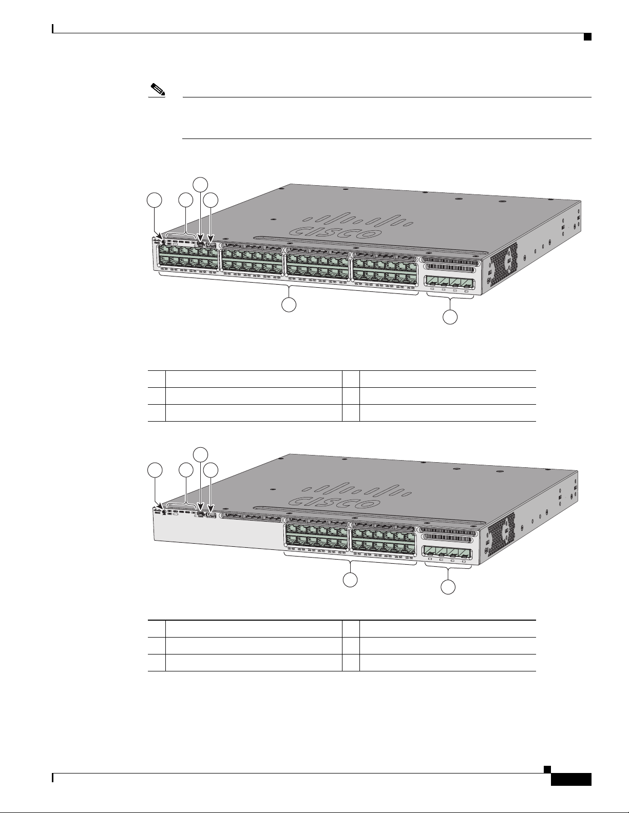
All of the switches have similar components. See Figure 1-1 and Figure 1-2 for examples.
1-4
Catalyst 3650 Switch Hardware Installation Guide
OL-29734-01
Page 7
Chapter 1 Product Overview
6
3
41
5
2
347809
0
1
X
1
3
X
1
2
X
2
4
X
2
5
X
3
6
X
3
7
X
4
8
X
A
CTV
C
ataly
st 365
0 48
P
oE
+ 2X10G
TE
3
G
1
G
2
G
3
G
4
TE
4
A
CTV
Note The illustrations of the Catalyst 3650 switch are not intended to depict any particular color
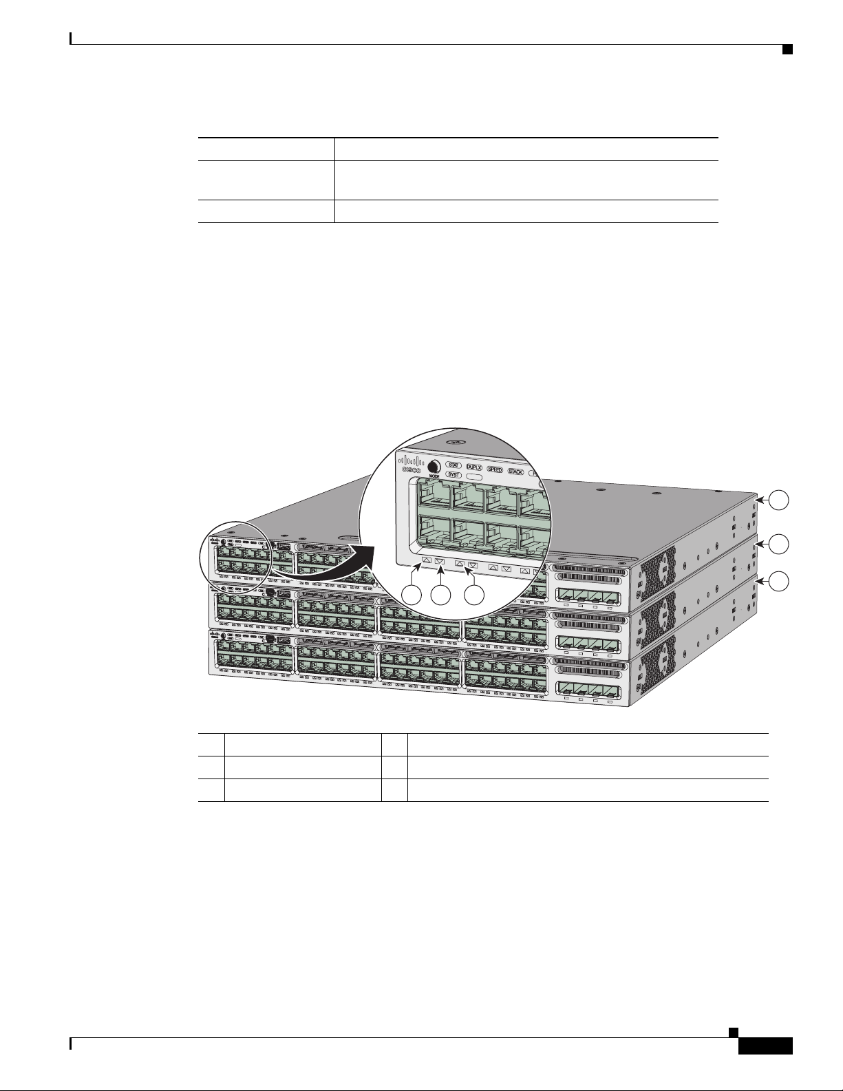
Figure 1-1 Catalyst 3650-48PD-L Switch Front Panel
Front Panel
scheme. They are provided as a reference for various features and markings described within this
guide.
Figure 1-2 Catalyst 3650-24PS-L Switch Front Panel
1 Mode button 4 USB Type A storage port
2 Status LEDs 5 10/100/1000 PoE+ Ethernet ports
3 USB mini-Type B (console) port 6 Uplink ports
3
2
41
347615
C
ataly
st 365
0 48
P
oE+ 2X
0
1
X
1
2
X
1
3
X
2
4
X
G
5
10G
1
G
2
G
3
TE
3
G
4
TE
4
6
1 Mode button 4 USB Type A storage port
2 Status LEDs 5 10/100/1000 PoE+ Ethernet ports
3 USB mini-Type B (console) port 6 Uplink ports
OL-29734-01
Catalyst 3650 Switch Hardware Installation Guide
1-5
Page 8

Front Panel
10/100/1000 Ethernet Ports
The 10/100/1000 Ethernet ports use RJ-45 connectors with Ethernet pinouts. The maximum cable length
is 328 feet (100 meters). The 100BASE-TX and 1000BASE-T traffic requires Category 5, Category 5e,
or Category 6 unshielded twisted pair (UTP) cable. The 10BASE-T traffic can use Category 3 or
Category 4 UTP cable.
For information about the 10/100/1000 Ethernet port connections and specifications, see the
“10/100/1000 Ethernet Port Connections” section on page 2-19 and Appendix B, “Connector and Cable
Specifications.”
PoE and PoE+
The PoE+ ports use the same connectors as described in the “10/100/1000 Ethernet Ports” section on
page 1-6.
These PoE+ ports provide:
• Support for IEEE 802.3af-compliant powered devices (up to 15.4 W PoE per port) and support for
IEEE 802.3at-compliant powered devices (up to 30 W PoE+ per port).
Chapter 1 Product Overview
• Support for Cisco-enhanced PoE.
• Support for prestandard Cisco powered devices.
• Configurable support for Cisco intelligent power management, including enhanced power
negotiation, power reservation, and per-port power policing.
See Table 1-12 on page 1-18 for the power supply matrix that defines the available PoE and PoE+ power
per port.
Note For information on 250-W AC power supply support on the PoE-capable switch models, refer to the
Release Notes for the Cisco Catalyst 3650 Switch on Cisco.com.
Note The output of the PoE+ circuit has been evaluated as a Limited Power Source (LPS) per IEC 60950-1.
For information about power supply modules, PoE+ port connections, and PoE+ specifications, see the
“Power Supply Modules” section on page 1-17, the “PoE+ Port Connections” section on page 2-21, and
Appendix B, “Connector and Cable Specifications.”
Management Ports
• Ethernet management port (see the “Ethernet Management Port” section on page 1-20)
• RJ-45 console port (EIA/TIA-232) (see the “RJ-45 Console Port” section on page 1-20)
1-6
• USB mini-Type B console port (5-pin connector)
You can connect the switch to a host such as a Windows workstation or a terminal server through the
Ethernet management port, the RJ-45 console port, or the USB console port (USB mini-Type B port).
The USB console port connection uses a USB Type A to 5-pin mini-Type B cable. The USB console
interface speeds are the same as the RJ-45 console interface speeds.
Catalyst 3650 Switch Hardware Installation Guide
OL-29734-01
Page 9
Chapter 1 Product Overview
USB Mini-Type B Port
The switch provides a USB mini-Type B console connection on the front panel, and the RJ-45 console
port on the switch rear panel. Console output is always active on both connectors, but console input is
active on only one connector at a time, with the USB connector taking precedence over the RJ-45
connector.
Use a USB type-A-to-USB 5-pin mini-Type B cable to connect a PC or other device to the switch. The
required USB cable is included in the optional accessory kit.
The connected device must include a terminal emulation application.
Windows PCs need a driver for the USB port. See the “Installing the Cisco Microsoft Windows USB
Device Driver” section on page C-3 for installation instructions.
When the switch detects a valid USB connection to a powered device, input from the RJ-45 console port
is immediately disabled, and input from the USB console is enabled. Removing the USB connection
immediately reenables input from the RJ-45 console connection. An LED on the switch front panel (see
Figure 1-4) is green when the USB console connection is enabled.
The switch provides a configurable inactivity timeout that reactivates the RJ-45 console if no input
activity has occurred on the USB console for a specified time period. After the USB console has been
deactivated due to a timeout, you can restore its operation by disconnecting and reconnecting the USB
cable. You can disable USB console operation by using Cisco IOS commands. See the switch software
configuration guide for details.
Front Panel
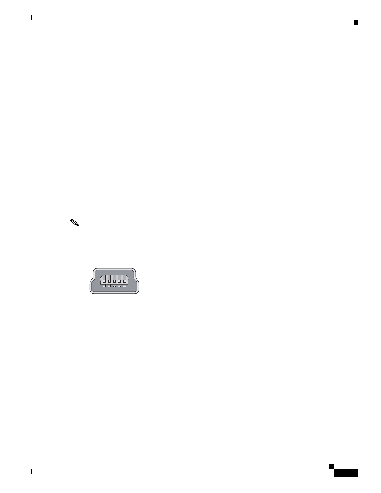
Note The 4-pin mini-Type B connectors resemble 5-pin mini-Type B connectors. They are not compatible.
Use only the 5-pin mini-Type B. See Figure 1-3.
Figure 1-3 USB Mini-Type B Port
You can use the command-line interface (CLI) to configure an inactivity timeout which reactivates the
RJ-45 console if the USB console has been activated and no input activity has occurred on the USB
console for a specified time period.
After the USB console deactivates due to inactivity, you cannot use the CLI to reactivate it. Disconnect
and reconnect the USB cable to reactivate the USB console. For information on using the CLI to
configure the USB console interface, see the switch software guide.
USB Type A Port
The USB Type A interface provides access to external USB flash devices (also known as thumb drives
or USB keys).
The interface supports Cisco USB flash drives with capacities from 64 MB to 1 GB.
253163
OL-29734-01
Cisco IOS software provides standard file system access to the flash device: read, write, erase, and copy,
as well as the ability to format the flash device with a FAT file system.
For more information about the switch management ports, see the switch software configuration guide
and the command reference on Cisco.com and the “Connector Specifications” section on page B-1.
Catalyst 3650 Switch Hardware Installation Guide
1-7
Page 10

Front Panel
Uplink Ports
The switch supports four SFP module slots that provide uplink ports to connect to other devices.
Depending upon the switch model, the uplink port support for SFP and SFP+ modules is:
• Four slots supporting only 1-Gigabit SFP modules.
• Two slots (left side) supporting only 1-Gigabit SFP modules and two slots (right side) supporting
either 10-Gigabit SFP+ modules or 1-Gigabit SFP modules.
• Four slots supporting either 1-Gigabit SFP modules or 10-Gigabit SFP+ modules.
For more information, see “Catalyst 3650 Switch Models” in Table 1-1 on page 1-1. For cable
specifications, see Appendix B, “Connector and Cable Specifications.”
Note If you insert an SFP+ module in an SFP module slot, the SFP+ module slot does not operate, and the
switch logs an error message. SFP modules can operate in SFP+ module slots.
SFP and SFP+ Modules
Chapter 1 Product Overview
LEDs
The SFP and SFP+ modules provide copper or fiber-optic connections to other devices. These
transceiver modules are field replaceable, and provide the uplink interfaces when installed in an SFP
module slot. The SFP modules have LC connectors for fiber-optic connections or RJ-45 connectors for
copper connections.
Use only Cisco SFP and SFP+ modules on the switch. For the latest information about supported
SFP/SFP+ modules, refer to the Cisco Transceiver Modules Compatibility Matrix documentation at:
http://www.cisco.com/en/US/products/hw/modules/ps5455/products_device_support_tables_list.html
For information about SFP modules, see your SFP module documentation and the “Installing SFP and
SFP+ Modules” section on page 2-17. For cable specifications, see Appendix B, “Connector and Cable
Specifications.”
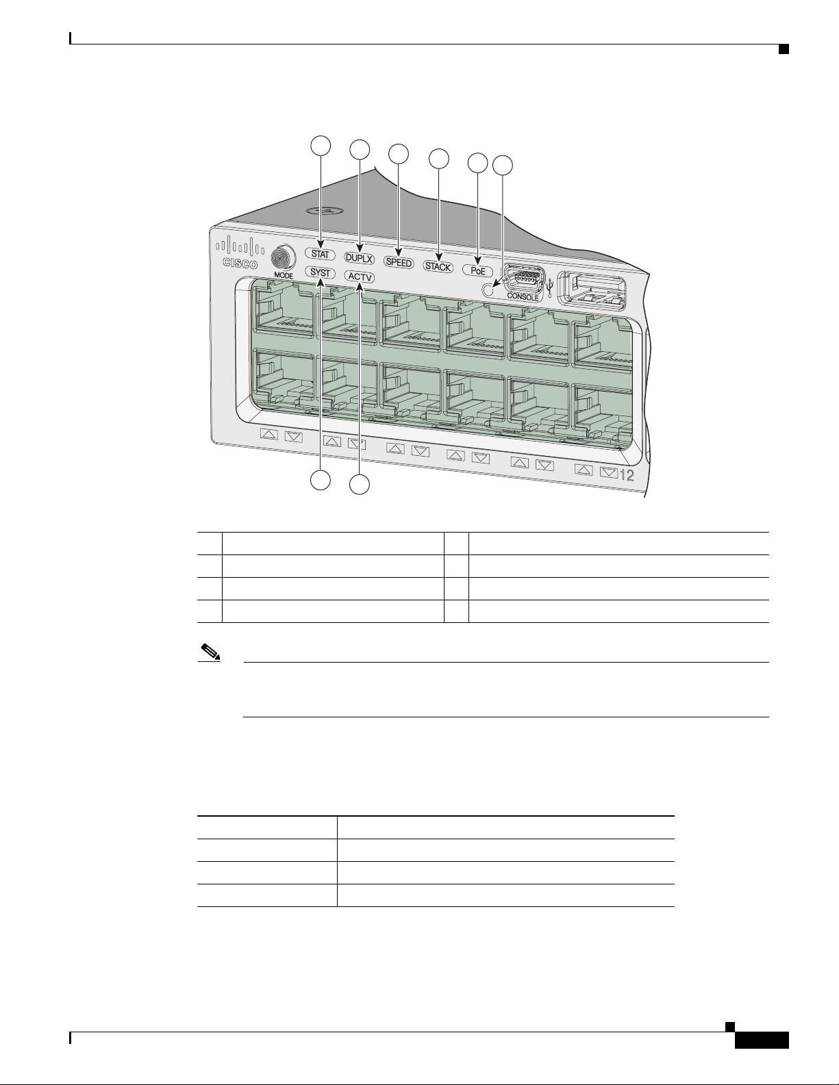
You can use the switch LEDs to monitor switch activity and its performance. Figure 1-4 shows the switch
LEDs and the Mode button that you use to select a port mode.
1-8
Catalyst 3650 Switch Hardware Installation Guide
OL-29734-01
Page 11
Chapter 1 Product Overview
Figure 1-4 Switch Front Panel LEDs
01X
Front Panel
1
2
3
4
5
6
SYST LED
7
8
1 STAT (status) 5
2 DUPLX (duplex) 6
1
PoE
CONSOLE (USB mini-Type B (console) port
347616
3 SPEED 7 SYST (system)
4 STACK 8 ACTV (active)
1. Only switches with PoE+ ports.
The illustrations of the Catalyst 3650 switch are not intended to depict any particular color scheme.
They are provided as a reference for various features and markings described within this
guide.
Table 1-2 SYST LED
Color System Status
Off System is not powered on.
Green System is operating normally.
Blinking green Switch is running POST.
OL-29734-01
Catalyst 3650 Switch Hardware Installation Guide
1-9
Page 12

Front Panel
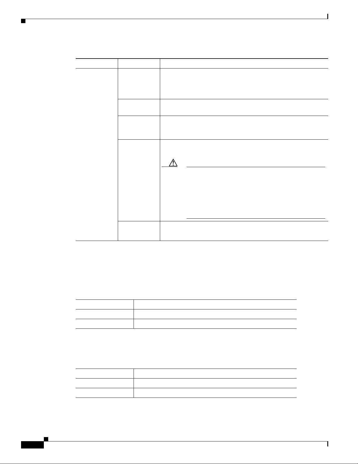
Table 1-2 SYST LED (continued)
Color System Status
Blinking amber There is a fault with one of the following:
Amber System is receiving power but is not functioning properly.
For information on the SYST LED colors during POST, see the “Diagnosing Problems” section on
page 5-1.
Port LEDs and Modes
Each Ethernet port, 1-Gigabit Ethernet module slot, and 10-Gigabit Ethernet module slot has a port LED.
These port LEDs, as a group or individually, display information about the switch and about the
individual ports. The port mode determines the type of information shown by the port LEDs. Tabl e 1 - 3
lists the mode LEDs and their associated port modes and meanings.
To select or change a mode, press the Mode button until the desired mode is highlighted. When you
change port modes, the meanings of the port LED colors also change. Ta b le 1-4 explains how to interpret
the port LED colors in different port modes.
When you press the Mode button on any switch in the switch stack, all the stack switches change to show
the same selected mode. For example, if you press the Mode button on the active switch to show the
SPEED LED, all the other switches in the stack also show the SPEED LED.
Chapter 1 Product Overview
• Power supply
• Fan module
Table 1-3 Port Mode LEDs
Mode LED Port Mode Description
STAT Port status The port status. This is the default mode.
SPEED Port speed The port operating speed: 10, 100 Mb/s, 1 or 10 Gb/s
DUPLX Port duplex mode The port duplex mode: full duplex or half duplex.
ACTV Active The active switch status.
1
PoE
1. Only switches with PoE+ ports.
PoE+ port power The PoE+ port status.
1-10
Catalyst 3650 Switch Hardware Installation Guide
OL-29734-01
Page 13

Chapter 1 Product Overview
Table 1-4 Meaning of Switch LED Colors in Different Modes
Port Mode Port LED Color Meaning
STAT
(port status)
SPEED
DUPLX
(duplex)
ACTV
(data active
switch)
STACK
(stack member)
Front Panel
Off No link, or port was administratively shut down.
Green Link present, no activity.
Blinking green Activity. Port is sending or receiving data.
Alternating
green-amber
Link fault. Error frames can affect connectivity, and errors such as
excessive collisions, CRC errors, and alignment and jabber errors
are monitored for a link-fault indication.
Amber Port is blocked by Spanning Tree Protocol (STP) and is not
forwarding data.
After a port is reconfigured, the port LED can be amber for up to 30
seconds as STP checks the switch for possible loops.
10/100/1000/SFP ports
Off Port is operating at 10 Mb/s.
Green Port is operating at 100 Mb/s.
Single green
Port is operating at 1000 Mb/s.
flash (on for
100 ms, off for
1900 ms)
SFP+ ports
Off Port is not operating.
Blinking green Port is operating at up to 10 Gb/s.
Off Port is operating in half duplex.
Green Port is operating in full duplex.
Off The switch is not the active switch.
Note For a standalone switch, this LED is off.
Green The switch is the active switch.
Amber Error during active switch election.
Blinking green Switch is a standby member of a data stack and assumes active
responsibilities if the current active switch fails.
Off No stack member corresponding to that member number.
Blinking green Stack member number.
Green Member numbers of other stack member switches.
OL-29734-01
Catalyst 3650 Switch Hardware Installation Guide
1-11
Page 14
Front Panel
Chapter 1 Product Overview
Table 1-4 Meaning of Switch LED Colors in Different Modes (continued)
Port Mode Port LED Color Meaning
1
PoE+
Off PoE+ is off.
If the powered device is receiving power from an AC power source,
the port LED is off even if the device is connected to the switch port.
Green PoE+ is on. The port LED is green when the switch port is providing
power.
Alternating
green and
PoE+ is denied because providing power to the powered device will
exceed the switch power capacity.
amber
Blinking amber PoE+ is off due to a fault or because it has exceeded a limit set in
the switch software.
Caution PoE+ faults occur when noncompliant cabling or
powered devices are connected to a PoE+ port. Use only
standard-compliant cabling to connect Cisco prestandard
IP Phones and wireless access points or
IEEE 802.3af-compliant devices to PoE+ ports. You must
remove from the network any cable or device that causes
a PoE+ fault.
USB Console LED
ACTV LED
Amber PoE+ for the port has been disabled.
Note PoE+ is enabled by default.
1. Only switches with PoE or PoE+ ports.
The USB console LED (Figure 1-4) shows whether there is an active USB connection to the port.
Table 1-5 USB Console Port LED
Color Description
Off USB console is disabled.
Green USB console is enabled.
Ta b le 1 - 6 A C T V LE D
Color Description
Off Switch is not the active switch.
Green Switch is the active switch or a standalone switch.
1-12
Catalyst 3650 Switch Hardware Installation Guide
OL-29734-01
Page 15
Chapter 1 Product Overview
C
a
ta
ly
s
t
3
6
5
0
4
8
P
oE
+
2
X
1
0
G
C
a
ta
ly
s
t
3
6
5
0
4
8
P
oE
+
2
X
1
0
G
T
E
3
T
E
4
T
E
3
C
a
ta
ly
s
t 3
6
5
0
4
8
P
oE
+
2
X
1
0
G
T
E
4
T
E
3
T
E
4
01X
5
64
1
2
3
01X
13X
1
2X
24X
2
5X
36X
37X
4
8X
01X
13X
1
2X
24X
2
5X
36X
37X
4
8X
01X
13X
1
2X
24X
2
5X
4
8X
ACT
V
A
C
T
V
A
C
T
V
Ca
t
a
l
y
s
t
3
6
5
0
4
8
P
oE
+
2
X
1
0
G
T
E
3
G
1
G
2
G
3
G
4
T
E
4
Ca
t
a
l
y
s
t
3
6
5
0
4
8
P
oE
+
2
X
1
0
G
T
E
3
G
1
G
2
G
3
G
4
T
E
4
C
a
tal
y
s
t
3
6
5
0
4
8
P
o
E
+
2
X
1
0
G
TE
3
G
1
G
2
G
3
G
4
T
E
4
STACK LED
Front Panel
Table 1-6 ACTV LED (continued)
Color Description
Amber An error occurred when the switch was selecting the active
switch, or another type of stack error occurred.
Slow blinking green Switch is in stack standby mode.
The STACK LED shows the sequence of member switches in a stack. Up to nine switches can be
members of a stack. The first nine port LEDs show the member number of a switch in a stack. Figure 1-5
shows the LEDs on the first switch, which is stack member number 1. For example, if you press the Mode
button and select Stack, the LED for port 1 blinks green. The LEDs for ports 2 and 3 are solid green, as
these represent the member numbers of other switches in the stack. The other port LEDs are off because
there are no more members in the stack.
Figure 1-5 STACK LED
1 Stack member 1 4 LED blinks green to show that this is switch 1 in the stack.
2 Stack member 2 5 LED is solid green to show that switch 2 is a stack member.
3 Stack member 3 6 LED is solid green to show that switch 3 is a stack member.
When you select the STACK LED mode, the representative STACK LEDs are green when the StackWise
ports are up, and the representative STACK LEDs are amber when the ports are down.
PoE+ LED
If the PoE mode is not selected on a switch with PoE+ ports, the PoE+ LED still shows detected PoE+
problems.
OL-29734-01
Catalyst 3650 Switch Hardware Installation Guide
1-13
Page 16

Front Panel
Uplink Ports LEDs
Chapter 1 Product Overview
Table 1-7 PoE+ Mode LED
Color PoE+ Status
Off PoE mode is not selected. None of the 10/100/1000 ports have been denied power
or are in a fault condition.
Green PoE mode is selected, and the port LEDs show the PoE+ status.
Blinking amber PoE mode is not selected. At least one of the 10/100/1000 ports has been denied
power, or at least one of the 10/100/1000 ports has a PoE+ fault.
The four uplink ports have four status LEDs. Each port LED is labeled according to its SFP and SFP+
module status.
For SFP ports, a G(x) labeling nomenclature is used, where G = 1 Gigabit and x = the port number. The
The G(x) label appears to the left of the uplink port LED.
For SFP+ ports, a TE(x) labeling nomenclature is used, where TE = 10 Gigabit and x = the port number.
The TE(x) label appears to the right of the uplink port LED.
An SFP+ module ports has two labels, G(x) and TE(x), because it supports both SFP and SFP+ modules.
The uplink port labeling layouts for the various switch models are:
• Four uplink port LEDs labeled G1, G2, G3, G4—This labeling represents four ports supporting SFP
modules.
• Four uplink port LEDs labeled G1, G2, G3, G4 and two right side uplink ports LEDs also labeled
TE3 and TE4—This labeling represents two ports (left side) supporting SFP modules and two ports
(right side) supporting SFP and SFP+ modules.
• Four uplink port LEDs labeled G1, G2, G3, G4 and TE1, TE2, TE3, TE4—This labeling represents
four slots supporting SFP and SFP+ modules.
Figure 1-6 shows an example of an uplink ports LED arrangement representing two SFP and two SFP+
ports (Catalyst 3650-48FD-S switch model).
1-14
Catalyst 3650 Switch Hardware Installation Guide
OL-29734-01
Page 17
Chapter 1 Product Overview
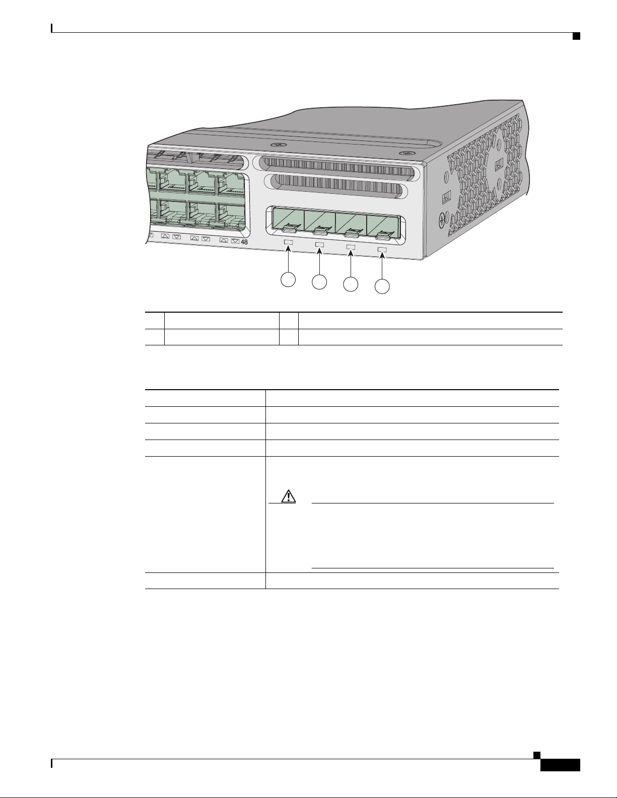
Figure 1-6 Uplink Ports LEDs
Catalyst 3650 48PoE+ 2X10G
G1
G2
Rear Panel
347665
G3
TE3
G4
TE4
1
2
3
4
1 G1 LED 3 G3, TE3 LED
2 G2 LED 4 G4, TE4 LED
Table 1-8 Uplink Ports LEDs
Color Uplink Ports Link Status
Off Link is off.
Green Link is on, no activity.
Blinking green Activity on a link, no faults.
Blinking amber Link is off due to a fault or because it has exceeded a limit set in the
switch software.
Caution Link faults occur when noncompliant cabling is connected
to an SFP or SFP+ port. Use only standard-compliant
cabling to connect to Cisco SFP and SFP+ ports. You must
remove from the ports any cable or device that causes a
link fault.
Rear Panel
OL-29734-01
Amber Link for the SFP or SFP+ has been disabled.
The switch rear panel includes StackWise connectors, ports, fan modules, and power supply modules.
See Figure 1-7.
Catalyst 3650 Switch Hardware Installation Guide
1-15
Page 18
Rear Panel
CON
SOLE
MGMT
M
GMT
347678
1 2
744
85 5 6
76
8
P
W
R
-
C2-250
W
A
C
P
W
R
-
C2-640
W
A
C
3 4
31 2
4
Chapter 1 Product Overview
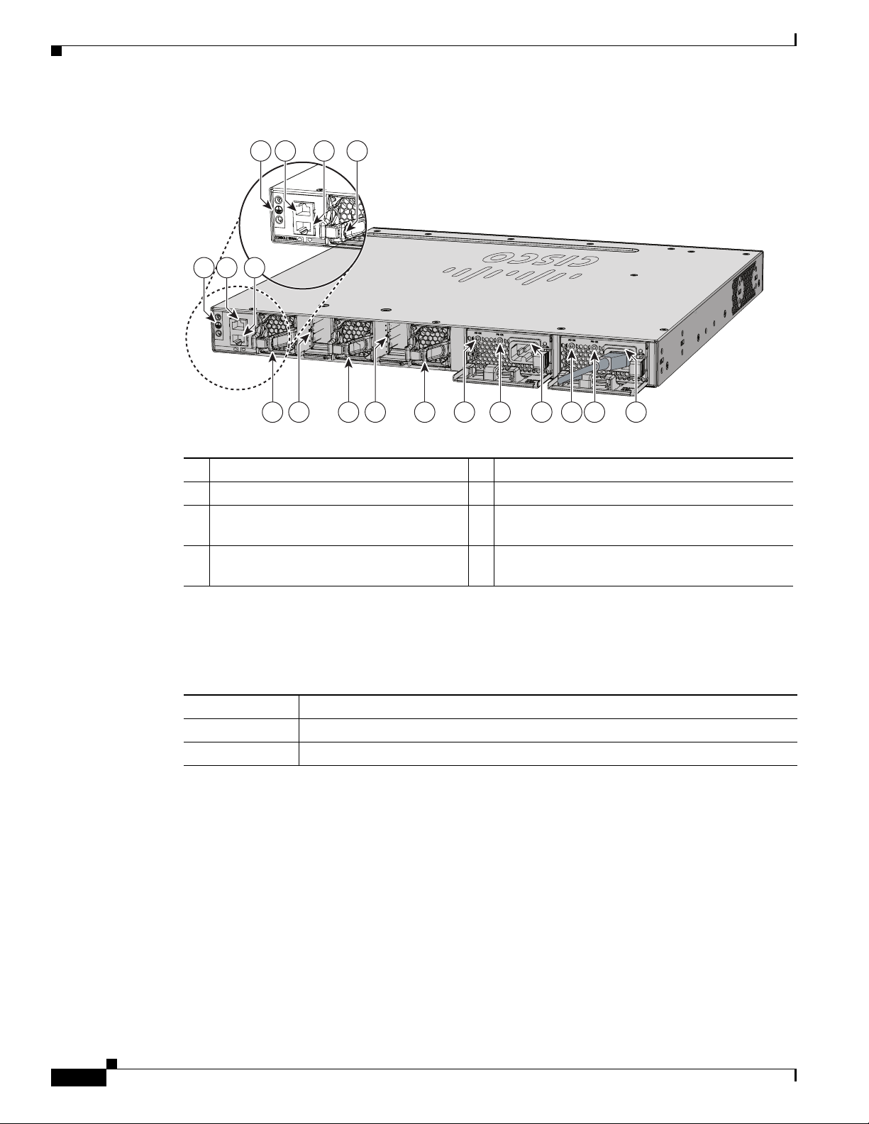
Figure 1-7 Catalyst 3650 Switch Rear Panel
1 Ground connector 5 StackWise port connector
2 CONSOLE (RJ-45 console port) 6 AC OK (input) status LED
3 MGMT (RJ-45 10/100/1000 management
port)
4 Fan module 8 Power supply modules (AC power supply
RJ-45 Console Port LED
Table 1-9 RJ-45 Console Port LED
Color RJ-45 Console Port Status
Off RJ-45 console is disabled. USB console is active.
Green RJ-45 console is enabled. USB console is disabled.
1. The USB console has priority over the RJ-45 console.
StackWise Ports
StackWise ports are used to connect switches in StackWise stacking configurations. StackWise cables
are used to connect the StackWise ports for stacking. For more information on StackWise cables, see the
“StackWise Cables” section on page B-5.
A StackWise adapter must be installed in the StackWise port to enable stacking. StackWise adapter
blanks installed in the StackWise ports is the default setup. For more information on StackWise adapters
and StackWise adapter blanks, see the “StackWise Adapters” section on page B-6 and the “StackWise
Adapter Blanks” section on page B-7.
7 PS OK (output) status LED
modules shown)
1
Catalyst 3650 Switch Hardware Installation Guide
1-16
OL-29734-01
Page 19

Chapter 1 Product Overview
For Catalyst 3650 switches where stacking is specified, StackWise adapters are preinstalled in the
StackWise ports, and optional StackWise cables can be ordered. When stacking is not specified, but is
required, the StackWise adapter blanks must be removed and StackWise adapters installed. For more
information on connecting switches for stacking see “Connecting to the StackWise Ports” section on
page 2-15.
Caution Use only approved cables, and connect only to similar Cisco equipment. Equipment might be damaged
if connected to nonapproved Cisco cables or equipment.
Note You cannot have a switch stack containing a mix of Catalyst 3650 and Catalyst 3850 switches.
Power Supply Modules
The 24- and 48-port switches are powered through one or two internal power supply modules.
Supported power supply modules:
• PWR-C2-250WAC=
• PWR-C2-640WAC=
Rear Panel
• PWR-C2-1025WAC=
• PWR-C2-640WDC=
The switch has two internal power supply module slots. You can use two AC modules, two DC modules,
a mixed configuration of one AC and one DC power supply module, or one power supply module and a
blank cover. The switch can operate with either one or two active power supply modules.
Table 1-1 shows the default power supply modules that ship with each switch model. All power supply
modules (except the blank covers) have internal fans. All switches ship with a blank cover in the second
power supply slot if switches are configured with only one power supply.
Caution Do not operate the switch with one power supply module slot empty. For proper chassis cooling, both
power supply module slots must be populated, or with either a power supply or a blank cover.
The 250-W and 640-W AC power supply modules are autoranging units that support input voltages
between 100 and 240 VAC. The 1025-W power supply module is an autoranging unit that supports input
voltages between 115 and 240 VAC. The 640-W DC power supply module supports input voltages
between -40 and -60 VDC.
Note For information on 250-W AC power supply support on the PoE-capable switch models, refer to the
Release Notes for the Cisco Catalyst 3650 Switch on Cisco.com.
Each AC power supply module has a power cord for connection to an AC power outlet. The 1025-W and
640-W modules use a 16-AWG cord (only North America). All other modules use an 18-AWG cord. The
DC-power supply module must be wired to a DC-power source.
OL-29734-01
Table 1-1 0 , Ta b le 1-11 , and Ta bl e 1- 12 show the PoE available and PoE requirements for Catalyst 3650
switches.
Catalyst 3650 Switch Hardware Installation Guide
1-17
Page 20
Rear Panel
Chapter 1 Product Overview
Table 1-10 Available PoE with AC Power Supply
Models Default Power Supply Available PoE Power
24-port data switch PWR-C2-250WAC= —
48-port data switch
24-port PoE switch PWR-C2-640WAC 390 W
48-port PoE switch
48-port full PoE switch PWR-C2-1025WAC 775 W
Table 1-11 Available PoE with DC Power Supply
1
Models Number of Power Supplies Available PoE Power
24-port PoE switch 1 390 W
2 780 W
48-port PoE switch 1 390 W
2 780 W
1. The 640-W DC (PWR-C2-640WDC) power supply is the only DC module.
Table 1-12 Switch Power Supply Requirements for PoE and PoE+
PoE Option 24-Port Switch 48-Port Switch
PoE (up to 15.4 per
port)
PoE+ (up to 30 W per
ports
1. A 48-port switch with one 640-W power supply provides up to 390 W of PoE to all ports.
(1) 640-W Power supply combinations:
• (1) 1025-W
• (1) 640-W + (1) 640-W
Power supply combinations:
• (1) 1025-W
• (1) 640-W + (1) 640-W
Power supply combinations:
• (2) 1025-W
1
1-18
The power supply modules have two status LEDs.
Table 1-13 Switch Power Supply Module LEDs
AC-Power Supply Module LEDs
AC OK Description PS OK Description
Off No AC input power. Off Output is disabled, or input is
outside operating range (AC LED
is off).
Green AC input power present. Green Power output to switch active.
Red Output has failed.
Catalyst 3650 Switch Hardware Installation Guide
OL-29734-01
Page 21
Chapter 1 Product Overview
A
CT
V
Fan Modules
Rear Panel
Table 1-13 Switch Power Supply Module LEDs (continued)
DC-Power Supply Module LEDs
DC OK Description PS OK Description
Off No DC input power. Off Output is disabled, or input is
outside operating range (DC LED
is off).
Green DC input power present. Green Power output to switch active.
Red Output has failed.
For information about replacing a power supply module, wiring a DC power supply module, and module
specifications, see Chapter 3, “Power Supply Installation,” and Appendix A, “Technical Specifications.”
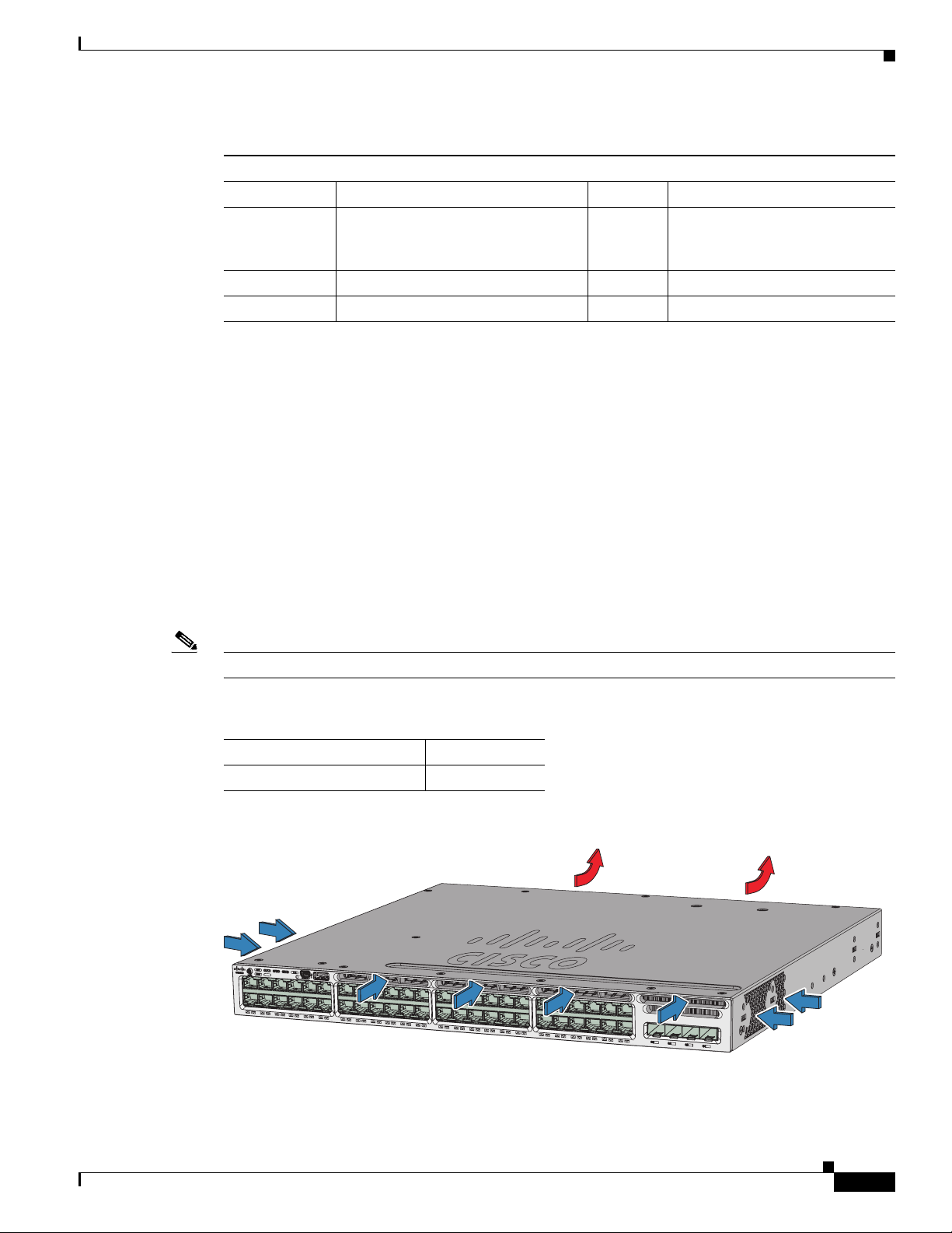
The switch has three internal hot-swappable 12-V fan modules. The air circulation system consists of
the fan modules and the power supply modules. The airflow patterns vary depending on the power supply
configuration.
Figure 1-8 shows the airflow patterns for the 24- and 48-port switches. The blue arrow shows cool air
flow, and the red arrow shows warm air flow. When the fan modules are operating properly, a green LED
is on at the top left corner of the fan assembly (viewed from the rear). If the fan fails, the LED turns to
amber. The switch can operate with two operational fans, but the failed fan should be replaced as soon
as possible to avoid a service interruption due to a second fan fault.
Note Three fans are required for proper cooling.
Table 1-14 Switch Fan Module
Fan Module Description
FAN-T1= Fan module
Figure 1-8 24- and 48-Port Switch Airflow Patterns
01
X
12
X
13
X
24
X
25
X
For information about installing a fan module and fan specifications, see Chapter 4, “Installing the Fan,”
and Appendix A, “Technical Specifications.”
347812
C
a
t
alyst
3650
48P
oE
+
4X
1
36X
37X
48X
G
OL-29734-01
Catalyst 3650 Switch Hardware Installation Guide
1-19
Page 22

Management Options
Management Ports
Ethernet Management Port
You can connect the switch to a host such as a Windows workstation or a terminal server through the
10/100/1000 Ethernet management port or one of the console ports (see Figure 1-7). The 10/100/1000
Ethernet management port is a VPN routing/forwarding (VRF) interface and uses a RJ-45 crossover or
straight-through cable.
Table 1-1 5 shows the Ethernet management port LED colors and their meanings.
Table 1-15 Ethernet Management Port LED
Color Description
Green Link up but no activity.
Blinking green Link up and activity.
Off Link down.
Chapter 1 Product Overview
RJ-45 Console Port
The RJ-45 console port connection uses the supplied RJ-45-to-DB-9 female cable.
Table 1-1 6 shows the RJ-45 console port LED colors and their meanings.
Table 1-16 RJ-45 Console LEDs
Color Description
Green RJ-45 console port is active.
Off The port is not active.
Management Options
• Configuration Wizard
The Configuration Wizard is a Web-based controller user interface (UI) that lets you complete the
initial wireless configuration after you configure the IP address, local username, and password or
authorization using the authentication server. Using the Web UI, you can configure the controller,
WLAN, and radios for all initial operations, establish management parameters, set security policies,
access software management commands, configure system logs, and other tasks.
For more information on using the Configuration Wizard, see the switch software configuration
guide on Cisco.com.
• Cisco Network Assistant
Cisco Network Assistant is a PC-based network management GUI application for LANs. You can
use the GUI to configure and manage switch clusters or standalone switches. Cisco Network
Assistant is available at no cost and can be downloaded from this URL:
1-20
http://www.cisco.com/pcgi-bin/tablebuild.pl/NetworkAssistant
Catalyst 3650 Switch Hardware Installation Guide
OL-29734-01
Page 23

Chapter 1 Product Overview
• Device Manager
• Cisco IOS CLI
• Cisco Prime Infrastructure
Management Options
For information on starting the Network Assistant application, see the Getting Started with Cisco
Network Assistant guide on Cisco.com.
You can use Device Manager, which is in the switch memory, to manage individual and standalone
switches. This web interface offers quick configuration and monitoring. You can access Device
Manager from anywhere in your network through a web browser. For more information, see the
getting started guide and the Device Manager online help.
You can configure and monitor the switch and switch cluster members from the CLI. You can access
the CLI by connecting your management station directly to the switch console port or by using
Telnet from a remote management station. See the switch command reference on Cisco.com for
more information.
Cisco Prime Infrastructure combines the wireless functionality of Cisco Prime Network Control
System (NCS) and the wired functionality of Cisco Prime LAN Management Solution (LMS), with
application performance monitoring and troubleshooting capabilities of Cisco Prime Assurance
Manager. For more information, see the Cisco Prime Infrastructure documentation on Cisco.com.
http://www.cisco.com/en/US/products/ps12239/index.html
Network Configurations
See the switch software configuration guide on Cisco.com for network configuration concepts and
examples of using the switch to create dedicated network segments and interconnecting the segments
through Gigabit Ethernet connections.
OL-29734-01
Catalyst 3650 Switch Hardware Installation Guide
1-21
Page 24

Management Options
Chapter 1 Product Overview
1-22
Catalyst 3650 Switch Hardware Installation Guide
OL-29734-01
Page 25

CHA P T E R
2
Switch Installation
This chapter describes how to install and connect a Catalyst 3650 switch. It also includes planning and
cabling considerations for stacking switches. Read the topics and perform the procedures in this order:
• Preparing for Installation, page 2-1
• Planning a Switch Data Stack, page 2-4
• Installing the Switch, page 2-9
• Connecting to the StackWise Ports, page 2-15
• Connecting Devices to the Ethernet Ports, page 2-19
• Where to Go Next, page 2-22
For initial switch setup, how to assign the switch IP address, and for powering information, see the
switch getting started guide on Cisco.com.
Preparing for Installation
• Safety Warnings, page 2-1
• Installation Guidelines, page 2-3
• Tools and Equipment, page 2-4
Safety Warnings
This section includes the basic installation caution and warning statements. Translations of the warning
statements appear in the Regulatory Compliance and Safety Information for the Catalyst 3650 Switch
document available at Cisco.com. Read this section before you start the installation procedure.
Warning
Warning
Before working on equipment that is connected to power lines, remove jewelry (including rings,
necklaces, and watches). Metal objects will heat up when connected to power and ground and can
cause serious burns or weld the metal object to the terminals.
Do not stack the chassis on any other equipment. If the chassis falls, it can cause severe bodily injury
and equipment damage.
Statement 48
Statement 43
OL-29734-01
Catalyst 3650 Switch Hardware Installation Guide
2-1
Page 26

Preparing for Installation
Chapter 2 Switch Installation
Warning
Warning
Warning
Warning
Warning
Warning
Ethernet cables must be shielded when used in a central office environment.
Statement 171
Voice over IP (VoIP) service and the emergency calling service do not function if power fails or is
disrupted. After power is restored, you might have to reset or reconfigure equipment to regain access
to VoIP and the emergency calling service. In the USA, this emergency number is 911. You need to be
aware of the emergency number in your country.
Statement 361
Do not work on the system or connect or disconnect cables during periods of lightning activity.
Statement 1001
Read the installation instructions before connecting the system to the power source.
Statement 1004
This unit is intended for installation in restricted access areas. A restricted access area can be
accessed only through the use of a special tool, lock and key, or other means of security.
Statement 1017
The plug-socket combination must be accessible at all times, because it serves as the main
disconnecting device.
Statement 1019
Warning
Warning
Warning
Warning
Warning
Use copper conductors only.
Statement 1025
This unit might have more than one power supply connection. All connections must be removed to
de-energize the unit.
Statement 1028
Only trained and qualified personnel should be allowed to install, replace, or service this equipment.
Statement 1030
Ultimate disposal of this product should be handled according to all national laws and regulations.
Statement 1040
For connections outside the building where the equipment is installed, the following ports must be
connected through an approved network termination unit with integral circuit protection: 10/100/1000
Ethernet.
Statement 1044
2-2
Catalyst 3650 Switch Hardware Installation Guide
OL-29734-01
Page 27

Chapter 2 Switch Installation
Preparing for Installation
Warning
Warning
Warning
Warning
Note The grounding architecture of this product is DC-isolated (DC-I).
To prevent the system from overheating, do not operate it in an area that exceeds the maximum
recommended ambient temperature of:
113°F (45°C)
No user-serviceable parts inside. Do not open.
Installation of the equipment must comply with local and national electrical codes.
To prevent airflow restriction, allow clearance around the ventilation openings to be at least:
3 in. (7.6 cm)
Installation Guidelines
Before installing the switch, verify that these guidelines are met:
• For the clearance to the front and rear panels, make sure that
Statement 1047
Statement 1073
Statement 1074
Statement 1076
–
Front-panel indicators can be easily read.
–
Clearance is at least 4.4 in. (11.1 cm) from switch rear panel.
–
Access to ports is sufficient for unrestricted cabling.
–
AC power cord can reach from the AC power outlet to the connector on the switch rear panel.
–
The SFP or SFP+ module minimum bend radius and connector length is met. See the SFP or
SFP+ module documentation for more information.
• For switches with the optional 1025-W power-supply module (PWR-C2-1025WAC=), first
rack-mount the switch before installing the power-supply module.
• Make sure power-supply modules and fan modules are securely inserted in the chassis before
moving the switch.
• When connecting or disconnecting the power cord on a switch that is installed above or below a
1025-W power supply-equipped switch, you might need to remove the module from the switch to
access the power cord.
• Cabling is away from sources of electrical noise, such as radios, power lines, and fluorescent
lighting fixtures. Make sure that the cabling is safely away from other devices that might damage
the cables.
• For copper connections on Ethernet ports, cable lengths from the switch to connected devices can
be up to 328 feet (100 meters).
• For cable requirements for SFP+ module connections, see the “Cable and Adapter Specifications”
section on page B-5. Each port must match the wave-length specifications on the other end of the
cable, and the cable must not exceed the maximum cable length.
OL-29734-01
Catalyst 3650 Switch Hardware Installation Guide
2-3
Page 28

Planning a Switch Data Stack
• Operating environment is within the ranges listed in Appendix A, “Technical Specifications.”
• Airflow around the switch and through the vents is unrestricted.
• Temperature around the unit does not exceed 113°F (45°C). If the switch is installed in a closed or
multirack assembly, the temperature around it might be greater than normal room temperature.
• Cisco Ethernet switches are equipped with cooling mechanisms, such as fans and blowers. However,
these fans and blowers can draw dust and other particles, causing contaminant buildup inside the
chassis, which can result in system malfunction. You must install this equipment in an environment
as free from dust and foreign conductive material (such as metal flakes from construction activities)
as is possible.
Tools and Equipment
Obtain these necessary tools and equipment:
• A number-2 Phillips screwdriver to rack-mount the switch.
• A Torx T15 screwdriver, or the Torx T15 key that ships with StackWise upgrade kits, to install the
StackWise adapter.
Chapter 2 Switch Installation
Verifying Switch Operation
Before you install the switch in a rack, or on a table or shelf, you should power on the switch and verify
that the switch passes POST. See the “Running Express Setup” section in the getting started guide for
the steps required to connect a PC to the switch and to run Express Setup.
Powering Off the Switch
After a successful POST, disconnect the power cord from the switch. Install the switch in a rack, on a
table, or on a shelf as described in the Chapter 2, “Installing the Switch,” section.
Planning a Switch Data Stack
Catalyst 3650 switches can share bandwidth by using data stacking.
• Switch Stacking Guidelines, page 2-5
• Data Stack Cabling Configurations, page 2-5
• Data Stack Bandwidth and Partitioning Examples, page 2-6
• Power-On Sequence for Switch Data Stacks, page 2-7
• Changes to Switch Stack Membership, page 2-8
2-4
Catalyst 3650 Switch Hardware Installation Guide
OL-29734-01
Page 29

Chapter 2 Switch Installation
Switch Stacking Guidelines
For general concepts and management procedures for switch stacks, see the switch software
configuration guide on Cisco.com.
A StackWise adapter must be installed in the stacking port to enable stacking. The StackWise cable
connects to the StackWise adapter in the stacking port. For switches ordered with stacking, the
StackWise adapters are pre-installed. If the switch is not ordered with stacking, the adapters must be
ordered separately and installed.
Before connecting the switches in a stack, observe these stacking guidelines:
• Size of the switch and any optional power-supply module. The 1025-W power-supply module is
longer than the other modules. Stacking switches with the same power-supply modules together
makes it easier to cable the switches. For switch dimensions, see Appendix A, “Technical
Specifications.”
• Length of StackWise cable. Depending on the configurations that you have, you might need
different-sized StackWise cables. If you do not specify the length of the StackWise cable, the
0.5-meter cable is supplied. If you need the 1-meter cable or the 3-meter cable, you can order it from
your Cisco supplier. For cable part numbers, see the “StackWise Cables” section on page B-5. The
“Data Stack Cabling Configurations” section on page 2-5 provides examples of recommended
configurations.
• Minimum bend radius and coiled diameter for StackWise cables. Cisco recommends a minimum
bend radius and coiled diameter for each StackWise cable. For more information, see Tab l e B-1 in
the “StackWise Cables Minimum Bend Radius and Coiled Diameter” section on page B-6.
• Data stacks can be created with up to nine switches in a stack.
Planning a Switch Data Stack
Note You cannot have a switch stack containing a mix of Catalyst 3650 and Catalyst 3850 switches.
Data Stack Cabling Configurations
Figure 2-1 is an example of a recommended configuration that uses the supplied 0.5-meter StackWise
cable. In this example, the switches are stacked in a vertical rack or on a table. This configuration
provides redundant connections.
OL-29734-01
Catalyst 3650 Switch Hardware Installation Guide
2-5
Page 30

Planning a Switch Data Stack
347682
CONSOLE
MGMT
CONSOLE
MGMT
CONSOLE
MGMT
CONSOLE
MGMT
PWR-C2-250WAC PWR-C2-640WAC
PWR-C2-250WAC PWR-C2-640WAC
PWR-C2-250WAC
PWR-C2-640WAC
PWR-C2-250WAC PWR-C2-640WAC
344183
The configuration example (Figure 2-1) uses the supplied 0.5-meter StackWise cable. The example
shows the full-ring configuration that provides redundant connections.
Figure 2-1 Data Stacking the Catalyst 3650 Switches in a Rack or on a Table Using the 0.5-meter
Figure 2-2 shows a recommended configuration when the switches are mounted side-by-side. Use the
1-meter and the 3-meter StackWise cables to connect the switches. This configuration provides
redundant connections.
Chapter 2 Switch Installation
StackWise Cables
Figure 2-2 Data Stacking up to Four Switches in a Side-by-Side Mounting
Data Stack Bandwidth and Partitioning Examples
This section provides examples of data stack bandwidth and possible data stack partitioning.
Figure 2-3 shows a data stack of Catalyst 3650 switches that provides full bandwidth and redundant
StackWise cable connections.
Figure 2-3 Example of a Data Stack with Full Bandwidth Connections
PWR-C2-250WAC PWR-C2-640WAC
1
2
3
PWR-C2-250WAC PWR-C2-640WAC
PWR-C2-250WAC PWR-C2-640WAC
347683
2-6
Catalyst 3650 Switch Hardware Installation Guide
OL-29734-01
Page 31

Chapter 2 Switch Installation
347684
1
2
PWR-C2-250WAC PWR-C2-640WAC
PWR-C2-250WAC PWR-C2-640WAC
PWR-C2-250WAC PWR-C2-640WAC
347685
1
2
3
PWR-C2-250WAC PWR-C2-640WAC
PWR-C2-250WAC PWR-C2-640WAC
PWR-C2-250WAC PWR-C2-640WAC
Figure 2-4 shows an example of a stack of Catalyst 3650 switches with incomplete StackWise cabling
connections. This stack provides only half bandwidth and does not have redundant connections.
Figure 2-4 Example of a Data Stack with Half Bandwidth Connections
Figure 2-5 and Figure 2-6 show data stacks of Catalyst 3650 switches with failover conditions. In
Figure 2-5, the StackWise cable is bad in link 2. Therefore, this stack provides only half bandwidth and
does not have redundant connections. In Figure 2-6, link 2 is bad. Therefore, this stack partitions into
two stacks, and the top and bottom switches become the active switch in the stack. If the bottom switch
is a member (not active or standby switch), it reloads.
Figure 2-5 Example of a Data Stack with a Failover Condition
Planning a Switch Data Stack
Figure 2-6 Example of a Partitioned Data Stack with a Failover Condition
PWR-C2-250WAC PWR-C2-640WAC
1
2
PWR-C2-250WAC PWR-C2-640WAC
PWR-C2-250WAC PWR-C2-640WAC
347686
Power-On Sequence for Switch Data Stacks
Consider these guidelines before you power on the switches in a stack:
• The sequence in which the switches are first powered on might affect the switch that becomes the
active switch and the standby switch.
• There are two ways to elect an active switch:
–
If you want a particular switch to become the active switch, configure it with the highest
priority. Among switches with same priority, the switch with the lowest MAC address becomes
the active switch.
–
If you want a particular switch to become the active switch, power on that switch first. This
switch remains the active switch until a reelection is required. After 2 minutes, power on the
other switches in the stack. If you have no preference as to which switch becomes the active
switch, power on all the switches in the stack within 1 minute. These switches participate in the
active switch election. Switches powered on after 2 minutes do not participate in the election.
If changes are made to the stack without powering down the switches, the following results can occur:
OL-29734-01
Catalyst 3650 Switch Hardware Installation Guide
2-7
Page 32

Planning a Switch Data Stack
• If two operating partial ring stacks are connected together using a stack cable, a stack merge can
• If some switches in the stack are completely separated from the stack, a stack split can occur.
• A stack split can occur on a full ring stack if:
• A stack split can occur in a partial ring stack if:
• In a split stack, depending on where the active and standby switches are located, either two stacks
Note These results depend on how the switches are connected. You can remove two or more switches
Chapter 2 Switch Installation
occur. This situation reloads the whole stack (all switches in the stack).
–
More than one running switch is removed without powering down.
–
More than one stack cable is removed without powering down.
–
A switch is removed without powering down.
–
A stack cable is removed without powering down.
might be formed (with the standby taking over as the new active switch in the newly formed stack)
or all the members in the newly formed stack might reload.
from the stack without splitting the stack.
For conditions that can cause a stack reelection or to manually elect the active switch, see the stacking
software configuration guide on Cisco.com at this URL:
http://www.cisco.com/go/cat3650_docs
Changes to Switch Stack Membership
If you replace a stack member with an identical model, the new switch functions with exactly the same
configuration as the replaced switch, assuming that the new switch (referred to as the provisioned
switch) is using the same member number as the replaced switch.
The operation of the switch stack continues uninterrupted during membership changes unless you
remove the active switch or you add powered-on standalone switches or switch stacks.
Note A switch stack always has one active switch and one standby switch. The active switch contains the
saved and running configuration files for the switch stack. If the active switch becomes unavailable, the
standby switch assumes the role of the active switch, and continues to the keep the stack operational.
For powered-on switches:
• Adding powered-on switches (merging) causes all switches to reload and elect a new active switch
from among themselves. The newly elected active switch retains its role and configuration. All other
switches change their stack member numbers to the lowest available numbers and use the stack
configuration of the newly elected active switch.
2-8
• Removing powered-on stack members causes the switch stack to divide (partition) into two or more
switch stacks, each with the same configuration. This can cause an IP address configuration conflict
in your network. If you want the switch stacks to remain separate, change the IP address or addresses
of the newly created switch stacks.
If a newly created switch stack does not have an active switch or standby switch, the switch stack will
reload and elect a new active switch.
Catalyst 3650 Switch Hardware Installation Guide
OL-29734-01
Page 33

Chapter 2 Switch Installation
Note Make sure that you power off the switches that you add to or remove from the switch stack.
After adding or removing stack members, make sure that the switch stack is operating at full bandwidth.
Press the Mode button on a stack member until the Stack mode LED is on. The last two right port LEDs
on all switches in the stack should be green. Depending on the switch model, the last two right ports are
10-Gigabit Ethernet ports or small form-factor pluggable (SFP) module ports (10/100/1000 ports). If one
or both of these LEDs are not green on any of the switches, the stack is not operating at full bandwidth.
If you remove powered-on members but do not want to partition the stack:
• Power off the switches in the newly created switch stacks.
• Reconnect them to the original switch stack through their stack ports.
• Power on the switches.
Installing the Switch
Installing the Switch
• Rack-Mounting, page 2-10
• Table- or Shelf-Mounting, page 2-14
• After Installing the Switch, page 2-14
The illustrations shown in this section show the Catalyst 3650-48 PoE+ switch as an example. You can
install other Catalyst 3650 switches following the same procedures.
OL-29734-01
Catalyst 3650 Switch Hardware Installation Guide
2-9
Page 34

Installing the Switch
Rack-Mounting
To install the switch in a 19-inch rack, follow the instructions described in this section.
Chapter 2 Switch Installation
Warning
To prevent bodily injury when mounting or servicing this unit in a rack, you must take special
precautions to ensure that the system remains stable. The following guidelines are provided to
ensure your safety:
• This unit should be mounted at the bottom of the rack if it is the only unit in the rack.
• When mounting this unit in a partially filled rack, load the rack from the bottom to the top with the heaviest
component at the bottom of the rack.
• If the rack is provided with stabilizing devices, install the stabilizers before mounting or servicing the unit in
the rack.
Statement 1006
The 19-inch brackets are included with the switch. Installing the switch in other rack types requires an
optional bracket kit not included with the switch. Figure 2-7 shows the mounting brackets and part
numbers.
2-10
Catalyst 3650 Switch Hardware Installation Guide
OL-29734-01
Page 35

Chapter 2 Switch Installation
2
1
333901
3 4 5
Figure 2-7 Rack-Mounting Brackets
Installing the Switch
2 Extension rails and brackets for four-point
mounting, includes 19-inch brackets.
1 19-inch brackets (RACK-KIT-T1=) 4 23-inch brackets (RACK-KIT-T1=)
(4PT-KIT-T1=)
3 ETSI brackets (RACK-KIT-T1=)
Attaching the Rack-Mount Brackets
To install the switch in a rack, use four Phillips flat-head screws to attach the long side of the brackets
to the switch for the front- or rear-mounting positions (Figure 2-8). Use four screws to attach the
brackets for the front-mounting position.
OL-29734-01
5 24-inch brackets (RACK-KIT-T1=)
Catalyst 3650 Switch Hardware Installation Guide
2-11
Page 36

Installing the Switch
Figure 2-8 Attaching Brackets for 19-inch Racks
1
W
R
-C2-640W
AC
2
Chapter 2 Switch Installation
2
3
Ca
ta
ly
s
t 3
6
5
0
4
8
Po
E+ 4
X
1
0
G
2
2
3
2
Ca
ta
lys
t 3
6
5
0
4
8
Po
E+ 4
X
1
0
G
2
2
2
347813
2-12
1 Rear-mounting position
2 Number-8 Phillips flat-head screws
3 Front-mounting position
Catalyst 3650 Switch Hardware Installation Guide
OL-29734-01
Page 37

Chapter 2 Switch Installation
Mounting the Switch in a Rack
After the brackets are attached to the switch, use the supplied Phillips machine screws to attach the
brackets to the rack (Figure 2-10). Use the black Phillips machine screw to attach the cable guide to the
left or right bracket.
When you complete the switch installation, see the “After Installing the Switch” section on page 2-14
for more information switch configuration.
Figure 2-9 Mounting the Switch in a Rack
2
1
Installing the Switch
3
A
C
T
V
1
X
1
2
X
1
3
X
2
4
X
2
5
X
3
6
X
3
7
X
C
atal
y
s
t
365
0
48PoE+
4
8
X
2
X
10
4
G
347814
1 Phillips machine screw, black 3 Front-mounting position
2 Cable guide 4 Number-12 or number-10 Phillips machine
screws
When you complete the switch installation, see the “After Installing the Switch” section on page 2-14
for more information about switch configuration.
OL-29734-01
Catalyst 3650 Switch Hardware Installation Guide
2-13
Page 38

Installing the Switch
1
1
P
W
R
-C2-6
40WA
C
P
W
R
-C2-640
WA
C
CONSOLE
MGMT
Table- or Shelf-Mounting
To install the switch on a table or shelf, locate the adhesive strip with the rubber feet in the mounting-kit
envelope. Attach the four rubber feet to the recessed areas on the bottom of the chassis (see Figure 2-10).
Figure 2-10 Attaching the Adhesive Pads for Table- or Shelf-Mounting
Chapter 2 Switch Installation
1 Adhesive pads
When you complete the switch installation, see the “After Installing the Switch” section on page 2-14
for more information about the switch configuration.
After Installing the Switch
After the switch is installed, you might need to:
• Configure the switch by running Express Setup to enter the initial switch configuration. For
instructions, see the switch getting started guide that shipped with the switch and also on Cisco.com.
• Use the CLI setup program to enter the initial switch configuration. See Appendix C, “Configuring
the Switch with the CLI-Based Setup Program.”
• Connect to the front-panel ports. See the “Connecting Devices to the Ethernet Ports” section on
page 2-19.
Catalyst 3650 Switch Hardware Installation Guide
2-14
OL-29734-01
Page 39

Chapter 2 Switch Installation
Connecting to the StackWise Ports
Before connecting the StackWise cables, review the “Planning a Switch Data Stack” section on page 2-4.
Always use a Cisco-approved StackWise cable to connect the switches.
Caution Removing and installing the StackWise cable can shorten its useful life. Do not remove and install the
cable more often than is absolutely necessary (removing and installing it up to 200 times is supported).
Step 1 Remove the dust covers from the StackWise cables and store them for future use.
A StackWise adapter must be installed in the StackWise port to enable stacking. The default setup is that
StackWise adapter blanks are installed in the StackWise ports. If StackWise stacking is ordered with the
switch, StackWise adapters are already installed in the StackWise ports, and you can proceed to step 4.
Step 2 Remove the StackWise adapter blanks from each destination StackWise port using the Torx T15 Allen
key provided in the stacking kit (or a Torx T15 screwdriver), as shown in Figure 2-11. Store them for
future use.
Step 3 Install a StackWise adapter in each destination StackWise port, and secure in place using the supplied
Torx T15 key, or a Torx T15 screwdriver, as shown in Figure 2-12.
Connecting to the StackWise Ports
Note It is not necessary to remove the fan modules prior to removal or installation of the StackWise
adapter. If the installation is performed with the system powered-on, the fans must be left in the
installed position at all times.
Step 4 Connect the StackWise cable to the StackWise port on the switch rear panel:
a. Align the StackWise cable connector with the StackWise adapter in the StackWise port.
b. Insert the StackWise cable connector in to the StackWise port as shown in Figure 2-13. Make sure
that the Cisco logo is on the top side of the connector.
c. Finger-tighten the screws (clockwise direction).
Step 5 Connect the other end of the cable to the port on the other switch and finger-tighten the screws. Avoid
overtightening the screws.
OL-29734-01
Catalyst 3650 Switch Hardware Installation Guide
2-15
Page 40

Connecting to the StackWise Ports
C
ONSOLE
M
G
M
T
347822
1
4
2
3
5
Figure 2-11 Removing the StackWise Adapter Blank from a StackWise Port
Chapter 2 Switch Installation
1 Torx T15 screwdriver 4 StackWise adapter blank
2 Assembly screw 5 StackWise port
3 Cisco logo 6
Figure 2-12 Installing the StackWise Adapter in a StackWise Port
5
C
ONSOLE
M
G
M
T
347840
3
1
4
2
1 Torx T15 screwdriver 4 StackWise adapter
2 Assembly screw 5 StackWise port
3 Cisco logo
Catalyst 3650 Switch Hardware Installation Guide
2-16
OL-29734-01
Page 41

Chapter 2 Switch Installation
Figure 2-13 Connecting the StackWise Cable to the StackWise Adapter
Installing and Removing SFP and SFP+ Modules
3
C
ONSOLE
M
G
M
T
347841
21
1 StackWise cable 3 StackWise adapter installed in a StackWise port
2 Cisco logo
When you need to remove the StackWise cable from the connector, make sure to fully unscrew the
correct screws. When the connectors are not being used, replace the dust covers.
Note If the StackWise cable is difficult to remove, you can use a flat-blade screwdriver to assist with removing
the cable screws. The screwdriver only works for cable removal and is designed to slip off if used for
cable installation.
Installing and Removing SFP and SFP+ Modules
See these sections for information on SFPs and SFP+:
• Installing SFP and SFP+ Modules, page 2-17
• Removing SFP or SFP+ Modules, page 2-19
Installing SFP and SFP+ Modules
OL-29734-01
See the “SFP and SFP+ Modules” section on page 1-8, and the switch release notes on Cisco.com for
the list of supported SFP and SFP+ modules. Use only supported SFP modules on the switch.
For cable specifications, see Appendix B, “Connector and Cable Specifications.”
Catalyst 3650 Switch Hardware Installation Guide
2-17
Page 42

Installing and Removing SFP and SFP+ Modules
Chapter 2 Switch Installation
Warning
Class 1 laser product.
Statement 1008
• Do not remove the dust plugs from the SFP modules or the rubber caps from the fiber-optic cable
until you are ready to connect the cable. The plugs and caps protect the module ports and cables
from contamination and ambient light.
• Removing and installing an SFP module can shorten its useful life. Do not remove and insert any
SFP module more often than is necessary.
• To prevent ESD damage, follow your normal board and component handling procedures when
connecting cables to the switch and other devices.
Observe these precautions:
Step 1 Attach an ESD-preventive wrist strap to your wrist and to an earth ground surface.
Step 2 Find the send (TX) and receive (RX) markings that identify the top of the SFP module.
On some SFP modules, the send and receive (TX and RX) markings might be shown by arrows that show
the direction of the connection.
Step 3 If the SFP module has a bale-clasp latch, move it to the open, unlocked position.
Step 4 Align the module in front of the slot opening, and push until you feel the connector snap into place.
Figure 2-14 Installing an SFP Module in an Uplink Port
Cat
alyst 3650 48PoE+ 2X10G
48X
G1
G2
G
3
TE3
G4
TE4
Step 5
If the module has a bale-clasp latch, close it to lock the SFP module in place.
Step 6 Remove the SFP dust plugs and save.
Step 7 Connect the SFP cables.
347772
2-18
Catalyst 3650 Switch Hardware Installation Guide
OL-29734-01
Page 43

Chapter 2 Switch Installation
48X
Cat
alyst 365
0
48
PoE+
2X1
0
G
TE3
T
E4
Figure 2-15 Connecting an SFP Cable to an SFP Module Installed in an Uplink Port
Removing SFP or SFP+ Modules
Connecting Devices to the Ethernet Ports
G3
G4
347773
Step 1 Attach an ESD-preventive wrist strap to your wrist and to an earth ground surface.
Step 2 Disconnect the cable from the SFP module. For reattachment, note which cable connector plug is send
(TX) and which is receive (RX).
Step 3 Insert a dust plug into the optical ports of the SFP module to keep the optical interfaces clean.
Step 4 If the module has a bale-clasp latch, pull the bale out and down to eject the module. If you cannot use
your finger to open the latch, use a small, flat-blade screwdriver or other long, narrow instrument to open
it.
Step 5 Grasp the SFP module, and carefully remove it from the slot.
Step 6 Place the SFP module in an antistatic bag or other protective environment.
Connecting Devices to the Ethernet Ports
• 10/100/1000 Ethernet Port Connections, page 2-19
• PoE+ Port Connections, page 2-21
Caution Category 5e and Category 6 cables can store high levels of static electricity. Always ground the cables
to a suitable and safe earth ground before connecting them to the switch or other devices.
10/100/1000 Ethernet Port Connections
The 10/100/1000 Ethernet ports use RJ-45 connectors with Ethernet pinouts. The maximum cable length
is 328 feet (100 meters). The 100BASE-TX and 1000BASE-T traffic requires Category 5, Category 5e,
or Category 6 UTP cable. The 10BASE-T traffic can use Category 3 or Category 4 cable.
OL-29734-01
Catalyst 3650 Switch Hardware Installation Guide
2-19
Page 44

Connecting Devices to the Ethernet Ports
The autonegotiation feature is enabled by default on the switch. At this setting, the switch ports
configure themselves to operate at the speed of attached device. If the attached device does not support
autonegotiation, you can explicitly set the switch port speed and duplex parameters. To maximize
performance, either let the ports autonegotiate both speed and duplex, or set the port speed and duplex
parameters on both ends of the connection.
For simplified cabling, the automatic medium-dependent interface crossover (auto-MDIX) feature is
enabled by default on the switch. With auto-MDIX enabled, the switch detects the required cable type
for copper Ethernet connections and configures the interface accordingly. Therefore, you can use either
a crossover or a straight-through cable for connections to a switch 10/100/1000 Ethernet port regardless
of the type of device on the other end of the connection.
See the switch software configuration guide or the switch command reference on Cisco.com for more
information about enabling or disabling autonegotiation and auto-MDIX.
If auto-MDIX is disabled, use the guidelines in Tab l e 2-1 to select the correct cable for connecting the
switch 10/100/1000 Ethernet ports to other devices. See the “Cable and Adapter Specifications” section
on page B-5 for cable-pinout descriptions.
Chapter 2 Switch Installation
2-20
Catalyst 3650 Switch Hardware Installation Guide
OL-29734-01
Page 45

Chapter 2 Switch Installation
Table 2-1 Recommended Ethernet Cables (When Auto-MDIX is Disabled)
Connecting Devices to the Ethernet Ports
Device Crossover Cable
Switch to switch Yes No
Switch to hub Yes No
Switch to computer or server No Yes
Switch to router No Yes
Switch to IP phone No Yes
1. 100BASE-TX and 1000BASE-T traffic requires twisted four-pair, Category 5, Category 5e, or
Category 6 cable. 10BASE-T traffic can use Category 3 or Category 4 cable.
PoE+ Port Connections
The 10/100/1000 PoE+ ports have the same autonegotiation settings and cabling requirements that are
described in the “10/100/1000 Ethernet Port Connections” section on page 2-19. These ports can provide
PoE or PoE+ inline power.
PoE inline power supports devices compliant with the IEEE 802.3af standard, as well as prestandard
Cisco IP Phones and Cisco Aironet Access Points. Each port can deliver up to 15.4 W of PoE.
PoE+ inline power supports devices compliant with the IEEE 802.3at standard, by delivering up to 30 W
of PoE+ power per port to all switch ports.
See Table 1-12 on page 1-18 for the power supply modules required to support PoE and PoE+ on 24- and
48-port switches.
1
Straight-Through Cable
1
For more information about the required power-supply module and the PoE specifications, see the
“Power Supply Modules” section on page 1-17 and Appendix A, “Technical Specifications.”
Note Many legacy powered devices, including older Cisco IP phones and access points that do not fully
support IEEE 802.3af, might not support PoE when connected to the switches by a crossover cable.
Caution PoE faults are caused when noncompliant cabling or powered devices are connected to a PoE port. Use
only standard-compliant cabling to connect Cisco prestandard IP Phones, wireless access points, or
IEEE 802.3af-compliant devices to PoE ports. A cable or device that causes a PoE fault must be removed
from the network.
Warning
Voice over IP (VoIP) service and the emergency calling service do not function if power fails or is
disrupted. After power is restored, you might have to reset or reconfigure equipment to regain access
to VoIP and the emergency calling service. In the USA, this emergency number is 911. You need to be
aware of the emergency number in your country.
Statement 361
OL-29734-01
Catalyst 3650 Switch Hardware Installation Guide
2-21
Page 46

Where to Go Next
Chapter 2 Switch Installation
Warning
Voltages that present a shock hazard may exist on Power over Ethernet (PoE) circuits if
interconnections are made using uninsulated exposed metal contacts, conductors, or terminals.
Avoid using such interconnection methods, unless the exposed metal parts are located within a
restricted access location and users and service people who are authorized within the restricted
access location are made aware of the hazard. A restricted access area can be accessed only through
the use of a special tool, lock and key or other means of security.
Where to Go Next
If the default configuration is satisfactory, the switch does not need further configuration. You can use
any of these management options to change the default configuration:
• Start the Network Assistant application, which is described in the Getting Started with Cisco
Network Assistant guide. Through this GUI, you can configure and monitor a switch cluster or an
individual switch.
• Use the CLI to configure the switch as a member of a cluster or as an individual switch from the
console. See the switch command reference on Cisco.com for information on using the CLI with the
switch.
• Use the Cisco Prime Infrastructure application.
Statement 1072
2-22
Catalyst 3650 Switch Hardware Installation Guide
OL-29734-01
Page 47

Power Supply Installation
This chapter describes how to install the power supply modules.
• Power Supply Module Overview, page 3-1
• Installation Guidelines, page 3-5
• Installing or Replacing an AC Power Supply, page 3-6
• Installing a DC Power Supply, page 3-7
• Finding the Power Supply Module Serial Number, page 3-12
Power Supply Module Overview
The switch operates with either one or two active power supply modules.
You can use two AC modules, two DC modules, one AC and one DC module, or one module and a blank
cover.
CHA P T E R
3
OL-29734-01
Note In a NEBS installation, you can use two DC modules or one DC module and a blank cover.
All switches ship with a blank cover in the second power supply slot if switches are configured with only
one power supply.
Table 3-1 describes the supported internal power supply modules.
Table 3-1 Power Supply Module Part Numbers and Descriptions
Part Number Description
PWR-C2-1025WAC= 1025-W AC power supply module
PWR-C2-640WAC= 640-W AC power supply module
PWR-C2-250WAC= 250-W AC power supply module
PWR-C2-640WDC= 640-W DC power supply module
PWR-C2-BLANK= Blank cover
Catalyst 3650 Switch Hardware Installation Guide
3-1
Page 48

Power Supply Module Overview
347623
PWR-C2-1025WAC
AC OK
PS OK
3 5 6
4
1
2
For information on available PoE, see these sections:
• Table 1-10 on page 1-18 (available PoE with AC power supply)
• Table 1-11 on page 1-18 (available PoE with DC power supply)
• Table 1-12 on page 1-18 (switch power supply requirements for PoE and PoE+)
The 250-W and 640-W AC power supply modules are autoranging units that support input voltages
between 100 and 240 VAC. The 1025-W power supply module is an autoranging unit that supports input
voltages between 115 and 240 VAC. The 640-W DC power supply module has dual input feeds (A and
B) and supports input voltages between -36 and -72 VDC.
Note For information on 250-W AC power supply support on the PoE-capable switch models, refer to the
Release Notes for the Cisco Catalyst 3650 Switch on Cisco.com.
Each AC power supply module has a power cord for connection to an AC power outlet. The 1025-W and
640-W modules use a 16-AWG cord (only North America). All other modules use an 18-AWG cord. The
DC power supply module must be wired to a DC power source.
Figure 3-1 to Figure 3-4 show the power supply modules.
Chapter 3 Power Supply Installation
Figure 3-1 1025-W AC Power Supply
1 AC OK LED 4 AC power cord connector
2 PS OK LED 5 Release latch
3 AC power cord retainer 6 1025-W AC power supply module
Catalyst 3650 Switch Hardware Installation Guide
3-2
OL-29734-01
Page 49

Chapter 3 Power Supply Installation
P
S
OK
AC OK
P
W
R-C2-250W
AC
347622
3 5 6
4
1
2
P
S
OK
A
C O
K
P
W
R-C2-250W
AC
347622
3 5 6
4
1
2
Figure 3-2 640-W AC Power Supply Module
Power Supply Module Overview
1 AC OK LED 4 AC power cord connector
2 PS OK LED 5 Release latch
3 AC power cord retainer 6 640-W AC power supply module
Figure 3-3 250-W AC Power Supply Module
1 AC OK LED 4 AC power cord connector
OL-29734-01
2 PS OK LED 5 Release latch
3 AC power cord retainer 6 250-W AC power supply module
Catalyst 3650 Switch Hardware Installation Guide
3-3
Page 50

Power Supply Module Overview
DC OK
PWR-C2-640WDC
PS OK
D
C
I
N
P
U
T
-
36V
t
o
--
72V
=
=
21-
10.
5A
O
U
TP
U
T
640
W
MA
X
+
12V
=
=
/
20.
83
A
-
54V
=
=
/
7.
36 A
347784
1
8
2
3
7
4
5 6 5 4
9
347781
2
1
Figure 3-4 640-W DC Power Supply Module
1 640-W DC power supply module 6 Grounding terminal
2 DC OK LED 7 Release latch
3 PS OK LED 8 Extraction handle
4 Input power terminals (positive polarity) 9 Terminal block safety cover
5 Input power terminals (negative polarity)
Chapter 3 Power Supply Installation
If no power supply is installed in a power supply slot, install a power supply slot blank cover
(Figure 3-5).
Figure 3-5 Power Supply Slot Blank Cover
1 Release handles 2 Retainer clips
3-4
The power supply modules have two status LEDs.
Catalyst 3650 Switch Hardware Installation Guide
OL-29734-01
Page 51

Chapter 3 Power Supply Installation
Table 3-2 Switch Power Supply Module LEDs
AC Power Supply Module LEDs
AC OK Description PS OK Description
Off
(AC LED is
off)
Green AC input power present. Green Power output to switch.
DC Power Supply Module LEDs
DC OK Description PS OK Description
Off
(DC LED is
off)
Green DC input power present. Green Power output to switch.
Installation Guidelines
No AC input power. Off Output is disabled, or input is
outside operating range.
Red Output has failed.
No DC input power. Off Output is disabled, or input is
outside operating range.
Red Output has failed.
Installation Guidelines
Table 3-1 lists the switches and the compatible power-supply modules. Observe these guidelines when
removing or installing a power supply or fan module:
• Do not force the power supply or fan module into the slot. This can damage the pins on the switch
if they are not aligned with the module.
• A power supply that is only partially connected to the switch can disrupt the system operation.
• Remove power from the power-supply module before removing or installing the module.
• The power supply is hot-swappable. In some configurations, such as full PoE+ or power-sharing
mode, removing a power supply causes powered devices to shut down until the power budget
matches the input power of a single power supply. To minimize network interruption, hot swap the
power supply ensuring that the remaining supply has sufficient PoE power for all powered ports.
For the switch commands that display available power budget, see the software configuration guide.
Note For information on 250-W AC power supply support on the PoE-capable switch models, refer to the
Release Notes for the Cisco Catalyst 3650 Switch on Cisco.com.
Caution Do not operate the switch with one power-supply module slot empty. For proper chassis cooling, both
module slots must be populated, with either a power supply or a blank cover.
OL-29734-01
Catalyst 3650 Switch Hardware Installation Guide
3-5
Page 52

Installing or Replacing an AC Power Supply
Chapter 3 Power Supply Installation
Warning
Warning
Warning
Blank faceplates and cover panels serve three important functions: they prevent exposure to
hazardous voltages and currents inside the chassis; they contain electromagnetic interference (EMI)
that might disrupt other equipment; and they direct the flow of cooling air through the chassis. Do not
operate the system unless all cards, faceplates, front covers, and rear covers are in place.
Statement 1029
Do not reach into a vacant slot or chassis while you install or remove a module. Exposed circuitry
could constitute an energy hazard.
Only trained and qualified personnel should be allowed to install, replace, or service this equipment.
Statement 1030
Statement 206
Installing or Replacing an AC Power Supply
Step 1 Turn off the power at its source.
Step 2 Remove the power cord from the power cord retainer.
Step 3 Remove the power cord from the power connector.
Step 4 Press the release latch at the right side of the power supply module inward and slide the power supply
out (Figure 3-6).
Caution Do not leave the power-supply slot open for more than 90 seconds while the switch is operating.
Warning
Step 5 Insert the new power supply into the power-supply slot, and gently push it into the slot (Figure 3-6).
This unit might have more than one power supply connection. All connections must be removed to
de-energize the unit.
Statement 1028
When correctly inserted, the 250-W and 640-W power supplies (excluding the power cord retainer) are
flush with the switch rear panel. The 1025-W power-supply module extends 1.5 inches from the switch
rear panel.
3-6
Catalyst 3650 Switch Hardware Installation Guide
OL-29734-01
Page 53

Chapter 3 Power Supply Installation
347769
AC OK
PWR-C2-640WAC
PS OK
AC OK
PWR-C2-250WAC
PS OK
Figure 3-6 Inserting the AC-Power Supply in the Switch
Installing a DC Power Supply
347789
Step 6
PW
R-C2-640
WA
CONSOLE
MGMT
C
PW
R-C2-6
4
0
W
A
C
(Optional) Make a loop in the power cord and thread it through the power cord retainer (Figure 3-7).
Figure 3-7 AC-Power Supply with Power Cord Retainer
Step 7 Connect the power cord to the power supply and to an AC power outlet. Turn on the power at the power
source.
Step 8 Confirm that the power supply AC OK and PS OK LEDs are green. See Tab l e 1- 13 for a description of
the power supply module LEDs.
Installing a DC Power Supply
• Equipment That You Need, page 3-8
• Grounding the Switch, page 3-8
• Installing the DC Power Supply in the Switch, page 3-11
• Wiring the DC Input Power Source, page 3-11
OL-29734-01
Warning
An exposed wire lead from a DC-input power source can conduct harmful levels of electricity. Be sure
that no exposed portion of the DC-input power source wire extends from the terminal block plug.
Statement 122
Catalyst 3650 Switch Hardware Installation Guide
3-7
Page 54

Installing a DC Power Supply
Chapter 3 Power Supply Installation
Warning
Warning
Warning
Warning
Note The grounding architecture of this product is DC-isolated (DC-I).
Before performing any of the following procedures, ensure that power is removed from the DC circuit.
Statement 1003
This product relies on the building’s installation for short-circuit (overcurrent) protection. Ensure that
the protective device is rated not greater than: 25 A.
A readily accessible two-poled disconnect device must be incorporated in the fixed wiring.
Statement 1022
Hazardous voltage or energy may be present on power terminals. Always replace cover when
terminals are not in service. Be sure uninsulated conductors are not accessible when cover is in
place.
Statement 1086
Equipment That You Need
Statement 1005
• Ratcheting torque screwdriver with a number-2 Phillips head that exerts up to 15 pound-force inches
(lbf-in.) of pressure.
• Panduit crimping tool with optional controlled-cycle mechanism (model CT-720, CT-920,
CT-920CH, CT-930, or CT-940CH).
• Wire-stripping tools.
• 12-gauge copper ground wire (insulated or not) for the single-hole ground connection.
• 8-gauge copper ground wire (insulated or not) for the dual-hole ground connection.
• Dual-hole ground lug and two screws (included in the DC Power Supply Accessory Kit) and
single-hole ground lug and screw (included in the Switch Accessory Kit). The dual-hole lug is
required for the grounding of the switch in a NEBS installation where the DC supply is the only
NEBS compliant power supply option.
• Four leads of 12-gauge copper wire.
• Four fork-type terminals from the DC power supply accessory kit. The terminals must be the proper
size for M3 screws in a Dinkle DT-35-B25-style terminal block.
Grounding the Switch
Follow the grounding procedures at your site and observe these warnings:
Warning
This equipment must be grounded. Never defeat the ground conductor or operate the equipment in the
absence of a suitably installed ground conductor. Contact the appropriate electrical inspection
authority or an electrician if you are uncertain that suitable grounding is available.
Statement 1024
3-8
Catalyst 3650 Switch Hardware Installation Guide
OL-29734-01
Page 55

Chapter 3 Power Supply Installation
Insulation
Wire lead
0.5 in. (12.7 mm) ± 0.02 in. (0.5 mm)
60528
33
4022
Installing a DC Power Supply
Warning
When installing or replacing the unit, the ground connection must always be made first and
disconnected last.
Statement 1046
Caution Follow the grounding procedure instructions, and use a UL-listed lug (included in the accessory kit).
Follow these steps to install either a single-hole ground lug or a dual-hole ground lug on the switch.
Make sure to follow any grounding requirements at your site.
Step 1 Use the ground lug screw and the lug ring for a single-hole ground connection. Use the dual-hole lug for
a ground connection in a NEBS installation.
Step 2 Strip the 12-gauge or 8-gauge ground wire to 0.5 inch (12.7 mm) ± 0.02 inch (0.5 mm) (Figure 3-8).
Stripping more than the recommended amount of wire can leave exposed wire from the connector. Use
12-gauge copper ground wire for the single-hole ground connection. Use 8-gauge copper ground wire
for the dual-hole ground connection.
Figure 3-8 Stripping the Ground Wire
Step 3 Slide the open end of the ground lug over the exposed area of the wire.
Step 4 Using a Panduit crimping tool, crimp the ground lug to the wire (Figure 3-9).
Figure 3-9 Crimping the Ground Lug
Step 5
Use the ground screw to attach the single-hole ground lug to the switch rear panel. Use two ground
screws to attach the dual-hole lug to the switch rear panel (Figure 3-10).
Step 6 Using a ratcheting torque screwdriver, torque the ground-lug screws to 60 lbf-in. (960 ozf-in.).
Step 7 Connect the other end of the grounding wire to an appropriate grounding point at your site or to the rack.
OL-29734-01
Catalyst 3650 Switch Hardware Installation Guide
3-9
Page 56

Installing a DC Power Supply
347788
1
2
CO
NS
OLE
MGMT
CO
NS
OLE
MGMT
Figure 3-10 Attaching the Ground Lug and Wire Assembly
Chapter 3 Power Supply Installation
1 Single-hole ground screw and lug ring 2 Dual-hole ground adapter and dual-hole lug
3-10
Catalyst 3650 Switch Hardware Installation Guide
OL-29734-01
Page 57

Chapter 3 Power Supply Installation
347792
PWR-C2-640WDC
PWR-C2-640WAC
CONSOLE
MGMT
Installing the DC Power Supply in the Switch
Before installing the power supply, see the Installation Guidelines, page 3-5.
Step 1 Turn off DC power. To ensure that power is off, change the circuit breakers to the OFF position, and tape
the circuit-breaker switches in the OFF position.
Step 2 Remove the plastic safety cover from the power supply terminal blocks (Figure 3-4).
If you are not replacing a DC power supply, go to Step 5.
Step 3 Use a number-2 Phillips screwdriver to remove the DC-input power wires from the power terminals.
Step 4 Press the release latch at the right side of the power supply module inward, and pull the power supply out.
Step 5 Insert the power supply in the power-supply slot, and gently push it into the slot (Figure 3-11). When
correctly installed, the DC power supply (excluding the extraction handle) is flush with the switch rear
panel.
Figure 3-11 Inserting the DC Power Supply in the Switch
Installing a DC Power Supply
Step 6
Connect the input power as described in the “Wiring the DC Input Power Source” section.
Wiring the DC Input Power Source
Step 1 Using a wire-stripping tool, strip each of the four wires from the DC-input power source to the
appropriate length for the terminals.
Warning
Step 2 Using a Panduit crimping tool, crimp the fork-type terminals to the copper conductor, 90C, 12-AWG DC
Step 3 Connect the DC-input power terminals to the terminal blocks. See Figure 3-12 or Figure 3-13. Make sure
OL-29734-01
Use copper conductors only.
power input wires.
to match the polarity (negative to negative, positive to positive) when connecting the wires to the
terminal blocks. Connect the ground wire to a grounded metal rack or to earth ground if the switch is not
in a grounded rack.
Statement 1025
Catalyst 3650 Switch Hardware Installation Guide
3-11
Page 58

Finding the Power Supply Module Serial Number
Figure 3-12 DC Source A Isolated From Source B with No Common Ground
Chapter 3 Power Supply Installation
A+
+
Figure 3-13 DC Source A and Source B Connections with Common Ground
A+
+
Step 4 Torque all terminal block screws to 11 lbf-in.
Step 5 Replace the terminal block safety cover.
Step 6 Move the DC power source circuit-breakers to the ON position.
Step 7 Confirm that the power supply DC OK and PS OK LEDs are green. See Tab le 3-2 for a description of
A-
-
A-
-
B-
B-
B+
253447
-
+
B+
253446
-
+
the module LEDs.
Finding the Power Supply Module Serial Number
If you contact Cisco Technical Assistance regarding a power supply module, you need to know the serial
number. See Figure 3-14 to Figure 3-16 to find the serial number. You can also use the CLI to find out
the serial number.
Catalyst 3650 Switch Hardware Installation Guide
3-12
OL-29734-01
Page 59

Chapter 3 Power Supply Installation
Figure 3-14 1025-W AC Power Supply Serial Number
Figure 3-15 640-W and 250-W AC Power Supply Module Serial Number
Finding the Power Supply Module Serial Number
SN: AAANNNNXXXX
347803
SN: AAANNNNXXXX
347805
OL-29734-01
Catalyst 3650 Switch Hardware Installation Guide
3-13
Page 60

Finding the Power Supply Module Serial Number
Figure 3-16 640-W DC Power Supply Module Serial Number
Chapter 3 Power Supply Installation
SN: AAANNNNXXXX
347804
3-14
Catalyst 3650 Switch Hardware Installation Guide
OL-29734-01
Page 61

Overview
CHA P T E R
4
Installing the Fan
This chapter describes how to install a fan module.
• Overview, page 4-1
• Fan Module Installation, page 4-2
• Finding the Fan Module Serial Number, page 4-4
The switch has three fan modules. Fan modules are hot-swappable. A powered switch should always
have more than one operational fan. The switch can operate with two operational fans and one
nonfunctional fan, but the failed fan should be replaced as soon as possible to avoid a service interruption
due to a second fan fault.
Note Three fans are required for proper cooling.
OL-29734-01
Catalyst 3650 Switch Hardware Installation Guide
4-1
Page 62

Fan Module Installation
Chapter 4 Installing the Fan
Figure 4-1 Fan Module
1
2
4
1 Fan LED 3 Retainer clip
2 Exhaust vent 4 Extraction handles
Fan Module Installation
3
344200
Installation Guidelines
Warning
Note Fans should be removed or installed only when StackWise adapters or StackWise adapter blanks are
Only trained and qualified personnel should be allowed to install, replace, or service this equipment.
Statement 1030
installed in each port.
Observe these guidelines when removing or installing a fan module:
• Do not force the fan module into the slot. This can damage the pins on the switch if they are not
aligned with the module.
• A fan module that is only partially connected can disrupt the system operation.
• The switch supports hot swapping of the fan module. You can remove and replace the module
without interrupting normal switch operation.
4-2
Catalyst 3650 Switch Hardware Installation Guide
OL-29734-01
Page 63

Chapter 4 Installing the Fan
Installing a Fan Module
Step 1 Pinch the fan module release handle, and slide the module out.
Caution You should replace the fan module within 5 minutes to avoid overheating the switch.
Step 2 Install the fan module in the fan slot, and firmly push it into the slot, applying pressure to the end of the
module, not the extraction handles. When correctly inserted, the fan module is flush with the switch rear
panel. When the fan is operating, a green LED is on in the top left corner of the fan. See Figure 4-2.
Fan Module Installation
Warning
Do not reach into a vacant slot when installing or removing a module. Exposed circuitry is an energy
hazard.
Statement 206
Figure 4-2 Installing the Fan Module
CONSOLE
PWR
-C2-6
40WAC
MGMT
PWR
-C2-6
40WD
C
347794
1
1 Fan LED
OL-29734-01
Catalyst 3650 Switch Hardware Installation Guide
4-3
Page 64

Finding the Fan Module Serial Number
SN: XXXNNNNXXXX
334328,781-00761-01
Finding the Fan Module Serial Number
If you contact Cisco Technical Assistance regarding a fan module, you need to know the fan module
serial number. See Figure 4-3 for the serial number location.
Figure 4-3 Fan Module Serial Number
Chapter 4 Installing the Fan
4-4
Catalyst 3650 Switch Hardware Installation Guide
OL-29734-01
Page 65

Troubleshooting
• Diagnosing Problems, page 5-1
• Resetting the Switch, page 5-5
• Finding the Switch Serial Number, page 5-6
• Replacing a Failed Data Stack Member, page 5-6
Diagnosing Problems
The switch LEDs provide troubleshooting information about the switch. They show POST failures,
port-connectivity problems, and overall switch performance. You can also get statistics from the CLI, or
an SNMP workstation. See the software configuration guide, the switch command reference guide on
Cisco.com, or the documentation that came with your SNMP application for details.
CHA P T E R
5
Switch POST Results
Approximately 30 seconds after the switch powers on, it begins the power-on self-test (POST), which
can take up to 5 minutes to complete. During POST, the SYSTEM LED blinks green. When POST is
complete, the SYSTEM LED turns solid green, the ACTV LED is green if the switch is acting as the
active switch.
Note POST failures are usually fatal. Contact your Cisco technical support representative if your switch does
not pass POST.
Switch LEDs
Look at the port LEDs for information when troubleshooting the switch. See the “LEDs” section on
page 1-8 for descriptions of the LED colors and their meanings.
OL-29734-01
Catalyst 3650 Switch Hardware Installation Guide
5-1
Page 66

Diagnosing Problems
Switch Connections
Bad or Damaged Cable
Always examine the cable for marginal damage or failure. A cable might be just good enough to connect
at the physical layer, but it could corrupt packets as a result of subtle damage to the wiring or connectors.
You can identify this situation because the port has many packet errors or the port constantly flaps (loses
and regains link).
• Exchange the copper or fiber-optic cable with a known good cable.
• Look for broken or missing pins on cable connectors.
• Rule out any bad patch panel connections or media convertors between the source and destination.
If possible, bypass the patch panel or eliminate media convertors (fiber-optic-to-copper).
• Try the cable in another port to see if the problem follows the cable.
• For Catalyst 3650 switch StackWise cable, remove and inspect the cable and StackWise port for bent
pins or damaged connectors. If the StackWise cable is bad, replace it with a known good cable.
Chapter 5 Troubleshooting
Ethernet and Fiber Cables
Make sure that you have the correct cable:
• For Ethernet, use Category 3 copper cable for 10 Mbps UTP connections. Use either Category 5,
Category 5e, or Category 6 UTP for 10/100 or 10/100/1000 Mbps connections.
• Verify that you have the correct fiber-optic cable for the distance (100 meters or less) and port type.
Make sure that the connected device ports match and use the same type encoding, optical frequency,
and fiber type. For more information about cabling, see the “SFP and SFP+ Module Cable
Specifications” section on page B-7.
• Determine if a copper crossover cable was used when a straight-through was required, or the reverse.
Enable auto-MDIX on the switch, or replace the cable. See Tab le 2-1 for recommended Ethernet
cables.
Link Status
Verify that both sides have a link. A broken wire or a shut-down port can cause one side to show a link
even though the other side does not have a link.
A port LED that is on does not guarantee that the cable is functional. It might have encountered physical
stress, causing it to function at a marginal level. If the port LED does not turn on:
• Connect the cable from the switch to a known good device.
• Make sure that both ends of the cable are connected to the correct ports.
• Verify that both devices have power.
• Verify that you are using the correct cable type. See Appendix B, “Connector and Cable
Specifications” for more information.
5-2
• Look for loose connections. Sometimes a cable appears to be seated but is not. Disconnect the cable
and then reconnect it.
Catalyst 3650 Switch Hardware Installation Guide
OL-29734-01
Page 67

Chapter 5 Troubleshooting
10/100/1000 Port Connections
A port appears to malfunction:
• Verify the status of all ports. See Table 1-3 on page 1-10 for descriptions of the LEDs and their
meanings.
• Use the show interfaces privileged EXEC command to see if the port is error-disabled, disabled, or
shut down. Reenable the port if necessary.
• Verify the cable type. See Appendix B, “Connector and Cable Specifications.”
PoE and PoE+ Port Connections
A powered device connected to a PoE port does not receive power:
• Verify the status of all ports. See Tab l e 1-3 and Ta b l e 1-7 for descriptions of the LEDs and their
meanings.
• Use the show interfaces privileged EXEC command to see if the port is error-disabled, disabled, or
shut down. Reenable the port if necessary.
• Verify that the power supply installed in the switch meets the power requirements of your connected
devices. See the “Power Supply Modules” section on page 1-17 for more information.
• Verify the cable type. Many legacy powered devices, including older Cisco IP phones and access
points that do not fully support IEEE 802.3af might not support PoE when connected to the switch
by a crossover cable. Replace the crossover cable with a straight-through cable.
Diagnosing Problems
Caution Noncompliant cabling or powered devices can cause a PoE port fault. Use only compliant cabling to
Note The output of the PoE circuit has been evaluated as a limited power source (LPS) per IEC 60950.
SFP Modules
connect Cisco prestandard IP phones, wireless access points, or IEEE 802.3af-compliant devices.
Use only Cisco SFP modules.
• Inspect the uplink port and SFP module. Exchange the suspect module with a known good module.
• Verify that the module is supported on this platform. (The switch release notes on Cisco.com list the
SFP and SFP+ modules that the switch supports.)
• Use the show interfaces privileged EXEC command to see if the port or module is error-disabled,
disabled, or shut down. Reenable the port if needed.
• Make sure that all fiber connections are clean and securely connected.
• For CX1 module connections and fiber connections, make sure that cable routing does not violate
the minimum allowed cable bend radius. See the module documentation for specific cabling
requirements.
Note When ordering or using CX1 cables, ensure that the version identifier is 2 or higher.
OL-29734-01
Catalyst 3650 Switch Hardware Installation Guide
5-3
Page 68

Diagnosing Problems
• For long wave SFP+ modules, a mode conditioning patch might improve performance over
Interface Settings
Verify that the port or interface is not disabled or powered off. If a port or interface is manually shut
down on either side of the link, it does not come up until you reenable the interface. Use the show
interfaces privileged EXEC command to see if the interface is error-disabled, disabled, or shut down on
either side of the connection. If needed, reenable the interface.
Ping End Device
Ping from the directly connected switch first, and then work your way back port by port, interface by
interface, trunk by trunk, until you find the source of the connectivity issue. Make sure that each switch
can identify the end device MAC address in its Content-Addressable Memory (CAM) table.
Spanning Tree Loops
Chapter 5 Troubleshooting
maximum link distances with MMF connections.
STP loops can cause serious performance issues that look like port or interface problems.
A unidirectional link can cause loops. It occurs when the traffic sent by the switch is received by the
neighbor, but the traffic from the neighbor is not received by the switch. A broken cable, other cabling
problems, or a port issue could cause this one-way communication.
You can enable UniDirectional Link Detection (UDLD) on the switch to help identify unidirectional link
problems. For information about enabling UDLD on the switch, see the “Understanding UDLD” section
in the software configuration guide on Cisco.com.
Switch Performance
Speed, Duplex, and Autonegotiation
Port statistics that show a large amount of alignment errors, frame check sequence (FCS), or
late-collisions errors, might mean a speed or duplex mismatch.
A common issue occurs when duplex and speed settings are mismatched between two switches, between
a switch and a router, or between the switch and a workstation or server. Mismatches can happen when
manually setting the speed and duplex or from autonegotiation issues between the two devices.
To maximize switch performance and to ensure a link, follow one of these guidelines when changing the
duplex or the speed settings:
• Let both ports autonegotiate both speed and duplex.
• Manually set the speed and duplex parameters for the interfaces on both ends of the connection.
• If a remote device does not autonegotiate, use the same duplex settings on the two ports. The speed
parameter adjusts itself even if the connected port does not autonegotiate.
5-4
Catalyst 3650 Switch Hardware Installation Guide
OL-29734-01
Page 69

Chapter 5 Troubleshooting
Autonegotiation and Network Interface Cards
Problems sometimes occur between the switch and third-party network interface cards (NICs). By
default, the switch ports and interfaces autonegotiate. Laptops or other devices are commonly set to
autonegotiate, yet sometimes issues occur.
To troubleshoot autonegotiation problems, try manually setting both sides of the connection. If this does
not solve the problem, there could be a problem with the firmware or software on the NIC. You can
resolve this by upgrading the NIC driver to the latest version.
Cabling Distance
If the port statistics show excessive FCS, late-collision, or alignment errors, verify that the cable distance
from the switch to the connected device meets the recommended guidelines. See the “Cable and Adapter
Specifications” section on page B-5.
Resetting the Switch
Resetting the Switch
If you have configured a new switch with a wrong IP address, or if all of the switch LEDs start blinking
when you try to enter Express Setup mode, you can clear the IP address that is configured on the switch.
Note Resetting the switch reboots the switch.
To reset the switch:
1. Press and hold the Mode button (Figure 1-1 on page 1-5).
The switch LEDs begin blinking after about 2 seconds. If the LEDs above the mode button turn solid
green, you can release the Mode button and run Express Setup to configure the switch. If the LEDs
do not turn solid green, continue with the next step.
2. Continue holding down the Mode button. The LEDs stop blinking after an additional 8 seconds, and
then the switch reboots.
You can also configure the switch by using the CLI setup procedure. See Appendix C, “Configuring the
Switch with the CLI-Based Setup Program.”
OL-29734-01
Catalyst 3650 Switch Hardware Installation Guide
5-5
Page 70

Finding the Switch Serial Number
Finding the Switch Serial Number
If you contact Cisco Technical Assistance, you need to know the switch serial number. Figure 5-1 shows
the serial number location. You can also use the show version privileged EXEC command to see the
switch serial number.
Figure 5-1 Switch Serial Number Location
SN: XXXNNNNXXXX
CONSOLE
MGMT
Chapter 5 Troubleshooting
PWR
-C
2
-64
0
W
A
C
PWR
-C
2
-6
4
0
W
AC
347807, 781-00797-01
Replacing a Failed Data Stack Member
To replace a failed data stack member:
1. The replacement switch must be a Catalyst 3650 switch.
2. Power down the failed switch. Remove AC or DC input power.
3. Make sure the replacement switch is powered off, and then connect it to the stack.
If you had manually set the member numbers for the switch stack, manually assign the member
number of the failed switch to the replacement switch. To manually assign the stack member
number, see the switch software configuration guide on Cisco.com.
4. Make the same Gigabit Ethernet connections on the replacement switch that were on the failed
switch.
5. Reinstall any modules and cable connections.
6. Power on the replacement switch.
The replacement switch will have the same configuration for all the interfaces as the failed switch and
will function the same as the failed switch.
5-6
Catalyst 3650 Switch Hardware Installation Guide
OL-29734-01
Page 71

Technical Specifications
• Switch Specifications, page A-1
• Power Supply Module Specifications, page A-3
• Fan Module Specifications, page A-5
Switch Specifications
Table A-1 Environmental and Physical Specifications
Environmental Ranges
Operating temperature ranges and
altitude (AC power supply installed)
APPENDIX
Normal operating temperature
–5ºC to +45ºC, up to 5000 feet (1500m)
–5ºC to +40ºC, up to 10,000 feet (3000m)
1
and altitude:
A
–5ºC to +35ºC, up to 13,000 feet (4000m)
–5ºC to +30ºC, up to 16,400 feet (5000m)
Short-term exceptional conditions
–5ºC to +50ºC, up to 5000 feet (1500m)
–5ºC to +45ºC, up to 10,000 feet (3000m)
–5ºC to +40ºC, up to 13,000 feet (4000m)
–5ºC to +35ºC, up to 16,400 feet (5000m)
–5ºC to +45ºC, at sea level with single fan failure
1 2
:
OL-29734-01
Catalyst 3650 Switch Hardware Installation Guide
A-1
Page 72

Switch Specifications
Appendix A Technical Specifications
Table A-1 Environmental and Physical (continued)Specifications (continued)
Environmental Ranges
Operating temperature ranges and
altitude (DC power supply installed)
Normal operating temperature1 and altitudes:
–5ºC to +45ºC, up to 6000 feet (1800m)
–5ºC to +40ºC, up to 10,000 feet (3000m)
–5ºC to +35ºC, up to 13,000 feet (4000m)
–5ºC to +30ºC, up to 16,400 feet (5000m)
Short-term exceptional conditions
1 2
:
–5ºC to +55ºC, up to 6000 feet (1800m)
–5ºC to +50ºC, up to 10,000 feet (3000m)
–5ºC to +45ºC, up to 13,000 feet (4000m)
–5ºC to +40ºC, up to 16,400 feet (5000m)
–5ºC to +45ºC, at sea level with single fan failure
Relative humidity 5 to 96% (non-condensing)
Storage temperature –40 to 158° F (–40 to 70° C)
Storage altitude Up to 16,400 ft (5000 m)
Physical Specifications
Dimensions (H x W x D)
Dimensions include the chassis assembly as it is shipped:
three fans, two Stackwise adapter blanks, one power supply
blank, and the default power supply shipped with the unit.
Catalyst 3650 24-port non PoE switches
Catalyst 3650 24-port PoE+ switches
Catalyst 3650 48-port non PoE switches
Catalyst 3650 48-port PoE+ switches
Catalyst 3650 48-port Full PoE switches
Weight
1.73 x 17.5 x 17.625 in. (4.4 x 44.5 x 44.8 cm)
1.73 x 17.5 x 17.625 in. (4.4 x 44.5 x 44.8 cm)
1.73 x 17.5 x 17.625 in. (4.4 x 44.5 x 44.8 cm)
1.73 x 17.5 x 17.625 in. (4.4 x 44.5 x 44.8 cm)
1.73 x 17.5 x 19.125 in. (4.4 x 44.5 x 48.6 cm)
Weight includes the chassis assembly as it is shipped: three
fans, two Stackwise adapter blanks, one power supply
blank, and the default power supply shipped with the unit.
Catalyst 3650 24-port non PoE switches
Catalyst 3650 24-port PoE switches
Catalyst 3650 48-port non PoE switches
Catalyst 3650 48-port PoE switches
Catalyst 3650 48-port Full PoE switches
StackWise stacking adapter
StackWise adapter blank
1. Minimum ambient temperature for cold start is 32°F (0°C).
2. Occurring not more than in one-year period: 96 consecutive hours, 360 hours in total, or 15 occurrences.
15.15 lbs (6.87 kg)
16.00 lbs (7.26 kg)
15.90 lbs (7.21 kg)
16.75 lbs (7.6 kg)
17.20 ibs (7.8 kg)
0.25 lbs (0.11 kg)
0.1 lbs (0.05 kg)
A-2
Catalyst 3650 Switch Hardware Installation Guide
OL-29734-01
Page 73

Appendix A Technical Specifications
Power Supply Module Specifications
Table A-2 Environmental and Physical Specifications for the AC- and DC-Power Supply
Modules
Environmental Ranges
Operating temperature For the operating temperature ranges at various altitudes of AC and
DC power supply module powered switches, see Tab l e A- 1.
Storage temperature –40 to 158° F (–40 to 70° C)
Relative humidity 5 to 96% (non-condensing)
Altitude AC power supply: Up to 16,400 ft (5,000 m)
DC power supply: Up to 16,400 ft (5,000 m)
Physical Specifications
Weight
PWR-C2-1025WAC=
PWR-C2-640WAC=
PWR-C2-250WAC=
PWR-C2-640WDC=
PWR-C2-BLANK=
Dimensions (H x W x D)
PWR-C2-1025WAC
3.55 lb (1.61 kg)
3.1 lb (1.41 kg)
2.55 lb (1.16 kg)
2.75 lb (1.25 kg)
0.2 lb (0.09 kg)
1.58 x 3.75 x 13.25 in. (4.0 x 9.5 x 33.7 cm)
Power Supply Module Specifications
PWR-C2-640WAC
PWR-C2-250WAC
PWR-C2-640WDC
Table A-3 Power Specifications for AC Power 24- and 48-Port Switches
Power Specifications
Maximum output power PWR-C2-1025WAC: 1025 W
Input voltage range and frequency PWR-C2-1025WAC: 1025-W, 115 to 240 VAC (autoranging)
Input current PWR-C2-1025WAC:12–6 A
Output ratings PWR-C2-1025WAC: +12 V @ 20.83 A, –54 V@14.6 A
1.58 x 3.75 x 11.75 in. (4.0 x 9.5 x 29.8 cm)
1.58 x 3.75 x 11.75 in. (4.0 x 9.5 x 29.8 cm)
1.58 x 3.75 x 11.75 in. (4.0 x 9.5 x 29.8 cm)
PWR-C2-640WAC: 640 W
PWR-C2-250WAC: 250 W
50 to 60 Hz
PWR-C2-640WAC: 640-W, PWR-C2-250WAC: 250 W,
100 to 240 VAC (autoranging), 50 to 60 Hz
PWR-C2-640WAC: 8–4 A
PWR-C2-250WAC: 4–2 A
PWR-C2-640WAC: +12 V @ 20.83 A, –54 V@7.36 A
PWR-C2-250WAC: +12 V @ 20.83 A
OL-29734-01
Catalyst 3650 Switch Hardware Installation Guide
A-3
Page 74

Power Supply Module Specifications
Table A-3 Power Specifications for AC Power 24- and 48-Port Switches (continued)
Appendix A Technical Specifications
Total input BTU
1
PWR-C2-1025WAC: 3801 BTUs per hour, 1114 W
PWR-C2-640WAC: 2371 BTUs per hour, 695 W
PWR-C2-250WAC: 945 BTUs per hour, 277 W
Total output BTU
1
PWR-C2-1025WAC: 3497 BTUs per hour, 1025 W
PWR-C2-640WAC: 2183 BTUs per hour, 640 W
PWR-C2-250WAC: 853 BTUs per hour, 250 W
1. The total input and total output BTU ratings refer to input power to the power supply and output power to the switch. The
BTU ratings are based on 100 VAC for the 250-W and 640-W power supplies and 115 VAC for the 1100-W power supply.
Table A-4 Power Specifications for DC-Power 24- and 48-Port Switches
Power Specifications
Maximum output power PWR-C2-640WDC: 640 W
Input current PWR-C2-640WDC: 21–10.5 A
DC input voltage PWR-C2-640WDC: –36 to –72 VDC
Output ratings PWR-C2-640WDC: +12 V @ 20.83 A, –54 V@7.36 A
Voltage range domestic PWR-C2-640WDC: –36 VDC (minimum)
–48 VDC (nominal), –72 VDC (maximum)
Voltage range international PWR-C2-640WDC: –36 VDC (minimum)
–60 VDC (nominal), –72 VDC (maximum)
Total input BTU
Total output BTU
1
1
PWR-C2-640WDC 2444 BTUs per hour, 719 W
PWR-C2-640WDC: 2188 BTUs per hour, 640 W
Wire gauge for ground connection PWR-C2-640WDC: 12 AWG or 8 AWG
Branch circuit protection PWR-C2-640WDC: 25 A
1. The total input and total output BTU ratings refer to input power to the power supply and output power to the switch. The
BTU ratings are based on –48 VDC (nominal).
A-4
Catalyst 3650 Switch Hardware Installation Guide
OL-29734-01
Page 75

Appendix A Technical Specifications
Fan Module Specifications
Table A-5 Fan Module Environmental and Physical Specifications
Environmental Ranges
Operating temperature 23 to 176° F (–5 to 80° C)
Storage temperature –40 to 185° F (–40 to 85° C)
Relative humidity 5 to 96% (non-condensing)
Altitude Up to 16,400 ft (5,000 m)
Physical Specification
Dimensions (H x D x W) 1.62 x 1.73 x 4.24 in. (4.11 x 4.39 x 10.76 cm)
Weight 0.2 lb (0.07 kg)
Operating Specification
Airflow 20 cfm
Fan Module Specifications
OL-29734-01
Catalyst 3650 Switch Hardware Installation Guide
A-5
Page 76

Fan Module Specifications
Appendix A Technical Specifications
A-6
Catalyst 3650 Switch Hardware Installation Guide
OL-29734-01
Page 77

Connector and Cable Specifications
60915
2 3145678Pin Label
1
2
3
4
5
6
7
8
TP0+
TP0-
TP1+
TP2+
TP2-
TP1-
TP3+
TP3-
This chapter describes the connector and cable specifications.
• Connector Specifications, page B-1l
• Cable and Adapter Specifications, page B-5
Connector Specifications
• 10/100/1000 Ports, page B-1
• 10-Gigabit Ethernet CX1 (SFP+ Copper) Connectors, page B-2
• SFP and SFP+ Modules, page B-2
• 10/100/1000 Ethernet Management Port, page B-3
• Console Port, page B-4
APPENDIX
B
10/100/1000 Ports
OL-29734-01
The 10/100/1000 Ethernet ports on switches use RJ-45 connectors and Ethernet pinouts.
Figure B-1 10/100/1000 Port Pinouts
Catalyst 3650 Switch Hardware Installation Guide
B-1
Page 78

Connector Specifications
58476
10-Gigabit Ethernet CX1 (SFP+ Copper) Connectors
The 10-Gigabit Ethernet electrical modules use CX1 copper connectors similar to the one shown in
Figure B-2.
Note When ordering or using CX1 cables, ensure that the version identifier is 2 or higher.
The 10-Gigabit Ethernet optical modules use the connectors shown in Figure B-3 and Figure B-4.
Figure B-2 10-Gigabit Ethernet CX1 Copper Connector (example)
278541
Appendix B Connector and Cable Specifications
SFP and SFP+ Modules
Figure B-3, Figure B-4, and Figure B-5 show the SFP module connectors.
The switch supports the SFP module patch cable, a 0.5-meter, copper, passive cable with SFP module
connectors at each end (Figure B-6). This cable can be used (only with 1-Gigabit Ethernet SFP ports) to
connect two Catalyst 3650 switches in a cascaded configuration.
Figure B-3 Duplex LC Cable Connector
B-2
Catalyst 3650 Switch Hardware Installation Guide
OL-29734-01
Page 79

Appendix B Connector and Cable Specifications
57834
60915
2 3145678Pin Label
1
2
3
4
5
6
7
8
TP0+
TP0-
TP1+
TP2+
TP2-
TP1-
TP3+
TP3-
126809
Figure B-4 Simplex LC Cable Connector
Figure B-5 Copper SFP Module RJ-45 Connector
Connector Specifications
Figure B-6 SFP Module Patch Cable
10/100/1000 Ethernet Management Port
The 10/100/1000 Ethernet management port uses RJ-45 connectors with Ethernet pinouts. Figure B-7
shows the pinouts.
OL-29734-01
Catalyst 3650 Switch Hardware Installation Guide
B-3
Page 80

Connector Specifications
H5318
2 3145678Pin Label
1
2
3
4
5
6
7
8
RD+
RD-
TD+
NC
NC
TD-
NC
NC
345493
Console Port
Appendix B Connector and Cable Specifications
Figure B-7 10/100 Port Pinouts
The switch has two console ports: a USB 5-pin mini-Type B port on the front panel (see Figure B-8) and
an RJ-45 console port on the rear panel.
Figure B-8 USB Mini-Type B Port
345492
The USB console port uses a USB Type A to 5-pin mini-Type B cable, shown in Figure B-9. The USB
Type A-to-USB mini-Type B cable is not supplied. You can order an accessory kit (part
number 800-33434) that contains this cable.
Figure B-9 USB Type A-to-USB 5-Pin Mini-Type B Cable
B-4
Catalyst 3650 Switch Hardware Installation Guide
The RJ-45 console port uses an 8-pin RJ-45 connector (See Tabl e B- 2 and Tabl e B - 3 .) The supplied
RJ-45-to-DB-9 adapter cable is used to connect the console port of the switch to a console PC. You need
to provide a RJ-45-to-DB-25 female DTE adapter if you want to connect the switch console port to a
OL-29734-01
Page 81

Appendix B Connector and Cable Specifications
terminal. You can order a kit (part number ACS-DSBUASYN=) containing that adapter. For console port
and adapter pinout information, see Tab l e B- 2 and Tab le B- 3 .
Cable and Adapter Specifications
• StackWise Cables, page B-5
• StackWise Adapters, page B-6
• StackWise Adapter Blanks, page B-7
• SFP and SFP+ Module Cable Specifications, page B-7
• Four Twisted-Pair Cable Pinouts, page B-8
• Two Twisted-Pair Cable Pinouts, page B-8
• Identifying a Crossover Cable, page B-9
• Console Port Adapter Pinouts, page B-9
Cable and Adapter Specifications
StackWise Cables
Figure B-10 shows a StackWise stacking cable.
Figure B-10 StackWise Stacking Cable
OL-29734-01
347676
You can order these StackWise cables (nonhalogen) from your Cisco sales representative:
• STACK-T2-50CM= (0.5-meter cable)
• STACK-T2-1M= (1-meter cable)
• STACK-T2-3M= (3-meter cable)
Catalyst 3650 Switch Hardware Installation Guide
B-5
Page 82

Cable and Adapter Specifications
StackWise Cables Minimum Bend Radius and Coiled Diameter
Table B-1 specifies the minimum bend radius and coiled diameter for each StackWise cable.
Table B-1 StackWise Cables Minimum Bend Radius and Coiled Diameter
Cable Part Number Cable Length Minimum Bend Radius Minimum Coiled Diameter
STACK-T2-50CM 1.64 ft (0.5 m) 2.60 in. (66 mm) 5.20 in. (132 mm)
STACK-T2-1M 3.28 ft (1.0 m) 2.60 in. (66 mm) 5.20 in. (132 mm)
STACK-T2-3M 9.84 ft (3.0 m) 3.58 in. (91 mm) 7.17 in. (182 mm)
StackWise Adapters
A StackWise adapter must be installed in the stacking port to enable stacking. The StackWise cable
connects to the StackWise adapter in the stacking port. For switches ordered with stacking, the
StackWise adapters are preinstalled.
If the switches are not ordered with stacking, the adapters must be ordered separately and installed. You
can order a StackWise adapter as part of a StackWise stacking upgrade kit (part number
C3650-STACK-KIT=), that contains two adapters and a 0.5 m StackWise cable..
Appendix B Connector and Cable Specifications
Locating the StackWise Adapter Serial Number
If you contact Cisco Technical Assistance regarding a StackWise adapter, you need to know the serial
number. See Figure B-11 to find the serial number.
Figure B-11 Location of the Serial Number on the StackWise Adapter
SN: AAANNNNXXXX
347806, 781-00796-01
B-6
Catalyst 3650 Switch Hardware Installation Guide
OL-29734-01
Page 83

Appendix B Connector and Cable Specifications
347816
3
1
2
StackWise Adapter Blanks
A StackWise adapter blank is installed in the stacking port if stacking is not specified at the time of
ordering the switch. The StackWise adapter blank is screwed into the stacking port and must be removed
and replaced by a StackWise adapter if the port is to be used for stacking. Figure B-12 shows a
StackWise adapter blank.
Figure B-12 StackWise Adapter Blank
Cable and Adapter Specifications
1 StackWise adapter blank 3 Cisco label
2 Assembly screw
SFP and SFP+ Module Cable Specifications
Each port must match the wave-length specifications on each end of the cable, and the cable must not
exceed the stipulated cable length. Copper 1000BASE-T SFP module transceivers use standard four
twisted-pair, Category 5 cable at lengths up to 328 feet (100 meters).
For cabling specifications, refer to the Cisco Transceiver Modules data sheet at:
http://www.cisco.com/en/US/products/hw/modules/ps5455/products_data_sheets_list.html
Catalyst 3650 Switch Hardware Installation Guide
OL-29734-01
B-7
Page 84

Cable and Adapter Specifications
1 TPO+
2 TPO-
3 TP1+
6 TP1-
1 TP1+
Switch Router or PC
2 TP1-
3 TPO+
6 TPO-
4 TP2+
5 TP2-
7TP3+
8 TP3-
4TP3+
5TP3-
7 TP2+
8 TP2-
65272
Switch
3 TD+
6 TD–
1 RD+
2 RD–
Router or PC
3 RD+
6 RD–
1 TD+
2 TD–
Four Twisted-Pair Cable Pinouts
Figure B-13 Four Twisted-Pair Straight-Through Cable Schematic
Figure B-14 Four Twisted-Pair Crossover Cable Schematic
Appendix B Connector and Cable Specifications
Switch Switch
1 TP0+
2 TP0-
3 TP1+
6 TP1-
4 TP2+
5 TP2-
7 TP3+
8 TP3-
1 TP0+
2 TP0-
3 TP1+
6 TP1-
4 TP2+
5 TP2-
7 TP3+
8 TP3-
Two Twisted-Pair Cable Pinouts
Figure B-15 Two Twisted-Pair Straight-Through Cable Schematic
65274
B-8
Catalyst 3650 Switch Hardware Installation Guide
OL-29734-01
Page 85

Appendix B Connector and Cable Specifications
Switch
3 TD+
6 TD–
1 RD+
2 RD–
Switch
3 TD+
6 TD–
1 RD+
2 RD–
Pin 1
H10632
Pin 8
Pin 1 on one connector and
pin 8 on the other connector
should be the same color.
Figure B-16 Two Twisted-Pair Crossover Cable Schematic
Identifying a Crossover Cable
To identify a crossover cable, hold the cable ends side-by-side, with the tab at the back. The wire
connected to the pin on the outside of the left plug should be the same color as the wire connected to the
pin on the outside of the right plug. (See Figure B-17.)
Figure B-17 Identifying a Crossover Cable
Cable and Adapter Specifications
Console Port Adapter Pinouts
The console port uses an 8-pin RJ-45 connector, which is described in Ta b le B-2 and Ta bl e B -3 . If you
did not order a console cable, you need to provide an RJ-45-to-DB-9 adapter cable to connect the switch
console port to a PC console port. You need to provide an RF-45-to-DB-25 female DTE adapter if you
want to connect the switch console port to a terminal. You can order a kit with an adapter (part
number ACS-DSBUASYN=). For console port and adapter pinout information, see Ta ble B- 2 and
Table B-3 .
Table B-2 lists the pinouts for the console port, the RF-45-to-DB-9 adapter cable, and the console device.
Table B-2 Console Port Signaling Using a DB-9 Adapter
OL-29734-01
Switch Console
Port (DTE)
Signal DB-9 Pin Signal
RTS 8 CTS
DTR 6 DSR
TxD 2 RxD
RJ-45-to-DB-9
Terminal Adapter
Console
Device
Catalyst 3650 Switch Hardware Installation Guide
B-9
Page 86

Cable and Adapter Specifications
Table B-2 Console Port Signaling Using a DB-9 Adapter (continued)
Appendix B Connector and Cable Specifications
Switch Console
Port (DTE)
Signal DB-9 Pin Signal
RJ-45-to-DB-9
Terminal Adapter
Console
Device
GND 5 GND
GND 5 GND
RxD 3 TxD
DSR 4 DTR
CTS 7 RTS
Table B-3 lists the pinouts for the console port, RJ-45-to-DB-25 female DTE adapter, and the
console device.
Note The RJ-45-to-DB-25 female DTE adapter is not supplied with the switch. You can order a kit with the
adapter (part number ACS-DSBUASYN=) from Cisco.
Table B-3 Console Port Signaling Using a DB-25 Adapter
Switch Console
Port (DTE)
Signal DB-25 Pin Signal
RJ-45-to-DB-25
Terminal Adapter
Console
Device
RTS 5 CTS
DTR 6 DSR
TxD 3 RxD
GND 7 GND
GND 7 GND
RxD 2 TxD
DSR 20 DTR
CTS 4 RTS
B-10
Catalyst 3650 Switch Hardware Installation Guide
OL-29734-01
Page 87

Configuring the Switch with the CLI-Based Setup Program
This appendix provides a CLI-based setup procedure for a Catalyst 3650 standalone switch or a switch
stack. To set up the switch by using Express Setup, see the Catalyst 3650 Switch Getting Started Guide.
Before connecting the switch to a power source, review the safety warnings in Chapter 2, “Switch
Installation.”
• Accessing the CLI, page C-1
• Entering the Initial Configuration Information, page C-5
Accessing the CLI
APPENDIX
C
Accessing the CLI Through Express Setup
You can access the CLI on an unconfigured switch by placing the switch in Express Setup mode and then
connecting a switch Ethernet port or the Ethernet management port to the Ethernet port of your PC or
workstation. To put the switch into Express Setup mode, follow the steps described in the Catalyst 3650
Getting Started Guide for powering on the switch and using Express Setup.
When the switch is in Express Setup mode, open a Telnet session to the switch by entering the IP address
10.0.0.1. Enter the setup user EXEC command. Enter the information described in the “Entering the
Initial Configuration Information” section on page C-5.
After you have entered the configuration information for the switch, save it to flash memory by using
the write memory privileged EXEC command.
Note While in Express Setup mode, the IP address 10.0.0.1 remains active on the switch until you enter the
write memory command. You lose the Telnet connection after entering the write memory command.
For more information about using the CLI, see the command reference for this release.
Accessing the CLI Through a Console Port
You can enter Cisco IOS commands and parameters through the CLI.
OL-29734-01
Catalyst 3650 Switch Hardware Installation Guide
C-1
Page 88

Accessing the CLI
Note If you have stacked Catalyst 3650 switches, connect to the 10/100/1000 Ethernet management port or
RJ-45 Console Port
Step 1 Connect the RJ-45-to-DB-9 adapter cable to the 9-pin serial port on the PC. Connect the other end of the
Step 2 Start the terminal emulation program on the PC or the terminal. The program, frequently a PC
Step 3 Configure the baud rate and character format of the PC or terminal to match the console port
Appendix C Configuring the Switch with the CLI-Based Setup Program
console port of one of the stack switches. You can perform the initial configuration for the entire stack
on any switch in the stack.
Use one of these options to access the CLI:
• RJ-45 Console Port
• USB Console Port
The RJ-45 console port is on the rear panel of the switch.
cable to the switch console port.
application, such as HyperTerminal or ProcommPlus, makes communication between the switch and
your PC or terminal possible.
characteristics:
• 9600 baud
Step 4 Connect power to the switch as described in Chapter 3, “Power Supply Installation.”
Step 5 The PC or terminal displays the bootloader sequence. Press Enter to display the setup prompt. Follow
USB Console Port
Step 1 If you are connecting the switch USB console port (see Figure C-1) to a Windows-based PC for the first
• 8 data bits
• 1 stop bit
• No parity
• None (flow control)
the steps in the “Configuring the Setup Program” section on page C-5.
The USB mini-Type B port is on the front panel of the switch.
time, install the USB driver. See these sections for installation instructions:
–
“Installing the Cisco Microsoft Windows USB Device Driver” section on page C-3
–
“Uninstalling the Cisco Microsoft Windows USB Driver” section on page C-4
C-2
Catalyst 3650 Switch Hardware Installation Guide
OL-29734-01
Page 89

Appendix C Configuring the Switch with the CLI-Based Setup Program
ACTV
344194
Figure C-1 Connecting the USB Console Cable to the Catalyst 3650 Switch
Accessing the CLI
Step 2 Connect a USB cable to the PC USB port. Connect the other end of the cable to the switch mini-B
(5-pin-connector) USB console port. See Figure C-1.
Step 3 Start the terminal-emulation program on the PC or the terminal. The program, frequently a PC
application such as HyperTerminal or ProcommPlus, makes communication between the switch and
your PC or terminal possible.
Step 4 Configure the baud rate and character format of the PC or terminal to match the console port default
characteristics:
• 9600 baud
• 8 data bits
• 1 stop bit
• No parity
• None (flow control)
Step 5 Connect power to the switch as described in Chapter 3, “Power Supply Installation.”
Step 6 The PC or terminal displays the bootloader sequence. Press Enter to display the setup prompt. Follow
the steps in the “Configuring the Setup Program” section on page C-5.
Installing the Cisco Microsoft Windows USB Device Driver
OL-29734-01
A USB device driver must be installed the first time a Microsoft Windows-based PC is connected to the
USB console port on the switch.
To install the Microsoft Windows USB Device Driver:
Catalyst 3650 Switch Hardware Installation Guide
C-3
Page 90

Appendix C Configuring the Switch with the CLI-Based Setup Program
Accessing the CLI
Step 1 Obtain the Cisco USB console driver file from the Cisco.com web site and unzip it.
Note You can download the driver file from the Cisco.com site for downloading the switch software.
Step 2 Follow the documentation included with the driver.
Step 3 Connect the USB cable to the PC and the switch console port. The USB console port LED turns green,
and the Found New Hardware Wizard appears. Follow the instructions to complete the driver installation.
Uninstalling the Cisco Microsoft Windows USB Driver
Use the Windows Add or Remove Programs utility or the setup.exe file:
• Uninstalling the Cisco Microsoft Windows USB Driver Using the Add or Remove Programs Utility
• Uninstalling the Cisco Microsoft Windows USB Driver Using the Setup.exe Program
Uninstalling the Cisco Microsoft Windows USB Driver Using the Add or Remove Programs Utility
• Uninstalling the Cisco Microsoft Windows XP USB Driver
• Uninstalling the Cisco Microsoft Windows Vista and 7 USB Driver
Uninstalling the Cisco Microsoft Windows XP USB Driver
Note Disconnect the switch console terminal before uninstalling the driver.
Step 1 Click Start > Control Panel > Add or Remove Programs.
Step 2 Scroll to Cisco Virtual Com and click Remove.
Step 3 When the Program Maintenance window appears, select the Remove radio button. Click Next.
Uninstalling the Cisco Microsoft Windows Vista and 7 USB Driver
Note Disconnect the switch console terminal before uninstalling the driver.
C-4
Step 1 Click Start > Control Panel > Uninstall or change a program.
Step 2 Select Cisco Virtual Com and click Uninstall.
Step 3 When the Programs and Features window appears, click Ye s to confirm.
Catalyst 3650 Switch Hardware Installation Guide
OL-29734-01
Page 91

Appendix C Configuring the Switch with the CLI-Based Setup Program
Entering the Initial Configuration Information
Uninstalling the Cisco Microsoft Windows USB Driver Using the Setup.exe Program
Note Disconnect the switch console terminal before uninstalling the driver.
Step 1 Run setup.exe for Windows 32-bit or setup(x64).exe for Windows 64-bit. Click Next.
Step 2 The InstallShield Wizard for Cisco Virtual Com appears. Click Next.
Step 3 When the Program Maintenance window appears, select the Remove radio button. Click Next.
Step 4 When the Remove the Program window appears, click Remove.
Note For Windows Vista or 7, if a User Account Control warning appears, click Allow - I trust this program
to proceed.
Step 5 When the InstallShield Wizard Completed window appears, click Finish.
Entering the Initial Configuration Information
To set up the switch, you need to complete the setup program, which runs automatically after the switch
is powered on. You must assign an IP address and other configuration information necessary for the
switch to communicate with the local routers and the Internet. This information is also needed to use
Device Manager or Cisco Network Assistant to configure and manage the switch.
IP Settings
You need this information from your network administrator:
• Switch IP address
• Subnet mask (IP netmask)
• Default gateway (router)
• Enable secret password
• Enable password
• Telnet password
Configuring the Setup Program
If your switches are stacked and there are multiple console connections to individual switches in the
stack, the initial setup dialog appears at the console where you first press Enter.
Completing the setup program and an initial configuration for the switch:
OL-29734-01
Step 1 Enter Ye s at the following two prompts:
Would you like to enter the initial configuration dialog? [yes/no]: yes
Catalyst 3650 Switch Hardware Installation Guide
C-5
Page 92

Entering the Initial Configuration Information
At any point you may enter a question mark '?' for help.
Use ctrl-c to abort configuration dialog at any prompt.
Default settings are in square brackets '[]'.
Basic management setup configures only enough connectivity
for management of the system, extended setup will ask you
to configure each interface on the system.
Would you like to enter basic management setup? [yes/no]: yes
Step 2 Enter a host name for the switch, and press Return.
On a command switch, the host name is limited to 28 characters and on a member switch to 31
characters. Do not use -n, where n is a number, as the last character in a host name for any switch.
Enter host name [Switch]: host_name
Step 3 Enter an enable secret password, and press Return.
The password can be from 1 to 25 alphanumeric characters, can start with a number, is case sensitive,
allows spaces, but ignores leading spaces. The secret password is encrypted, and the enable password is
in plain text.
Enter enable secret: secret_password
Appendix C Configuring the Switch with the CLI-Based Setup Program
Step 4 Enter an enable password, and press Return.
Enter enable password: enable_password
Step 5 Enter a virtual terminal (Telnet) password, and press Return.
The password can be from 1 to 25 alphanumeric characters, is case sensitive, allows spaces, but ignores
leading spaces.
Enter virtual terminal password: terminal-password
Step 6 To configure the country code, enter yes and press Return.
Do you want to configure country code? [no]: yes
Step 7 Enter the country code, and press Return.
Enter the country code[US]:US
Step 8 (Optional) Configure Simple Network Management Protocol (SNMP) by responding to the prompts. You
can also configure SNMP later through the CLI, Device Manager, or the Cisco Network Assistant
application. To configure SNMP later, enter no.
Configure SNMP Network Management? [no]: no
Step 9 Enter the interface name (physical interface or VLAN name) of the interface that connects to the
management network, and press Return. For this release, always use vlan1 as that interface.
Enter interface name used to connect to the
management network from the above interface summary: vlan1
C-6
Step 10 Configure the interface by entering the switch IP address and subnet mask and pressing Return. The IP
address and subnet masks shown are examples.
Configuring interface vlan1:
Configure IP on this interface? [yes]: yes
IP address for this interface: 10.4.120.106
Subnet mask for this interface [255.0.0.0]: 255.0.0.0
Catalyst 3650 Switch Hardware Installation Guide
OL-29734-01
Page 93

Appendix C Configuring the Switch with the CLI-Based Setup Program
You have completed the initial configuration of the switch, and the switch displays its configuration.
This is an example of the configuration output:
The following configuration command script was created:
hostname switch1
enable secret 5 $1$Ulq8$DlA/OiaEbl90WcBPd9cOn1
enable password enable_password
line vty 0 15
password terminal-password
no snmp-server
!
no ip routing
!
interface Vlan1
no shutdown
ip address 10.4.120.106 255.0.0.0
!
interface GigabitEthernet4/0/1
!
interface GigabitEthernet4/0/2
interface GigabitEthernet4/0/3
!
...<output abbreviated>
!
Entering the Initial Configuration Information
!
end
Step 11 These choices appear:
[0] Go to the IOS command prompt without saving this config.
[1] Return back to the setup without saving this config.
[2] Save this configuration to nvram and exit.
If you want to save the configuration and use it the next time the switch reboots, select
option 2 to save it in nonvolatile RAM (NVRAM).
Enter your selection [2]:2
Make your selection, and press Return.
After you complete the setup program, the switch can run the default configuration that you created. To
change this configuration or to perform other management tasks, enter commands at the
or use Cisco Network Assistant, or another management tool for further configuration.
Switch> prompt
OL-29734-01
Catalyst 3650 Switch Hardware Installation Guide
C-7
Page 94

Entering the Initial Configuration Information
Appendix C Configuring the Switch with the CLI-Based Setup Program
C-8
Catalyst 3650 Switch Hardware Installation Guide
OL-29734-01
 Loading...