

Page 1

Cisco Catalyst Switch Module 3110G,
3110X, and 3012 for IBM BladeCenter
Hardware
April 2008
Americas Headquarters
Cisco Systems, Inc.
170 West Tasman Drive
San Jose, CA 95134-1706
USA
http://www.cisco.com
Tel: 408 526-4000
800 553-NETS (6387)
Fax: 408 527-0883
Installation Guide
Text Part Number: OL-12192-01
Page 2

THE SPECIFICATIONS AND INFORMATION REGARDING THE PRODUCTS IN THIS MANUAL ARE SUBJECT TO CHANGE WITHOUT NOTICE. ALL
STATEMENTS, INFORMATION, AND RECOMMENDATIONS IN THIS MANUAL ARE BELIEVED TO BE ACCURATE BUT ARE PRESENTED WITHOUT
WARRANTY OF ANY KIND, EXPRESS OR IMPLIED. USERS MUST TAKE FULL RESPONSIBILITY FOR THEIR APPLICATION OF ANY PRODUCTS.
THE SOFTWARE LICENSE AND LIMITED WARRANTY FOR THE ACCOMPANYING PRODUCT ARE SET FORTH IN THE INFORMATION PACKET THAT
SHIPPED WITH THE PRODUCT AND ARE INCORPORATED HEREIN BY THIS REFERENCE. IF YOU ARE UNABLE TO LOCATE THE SOFTWARE LICENSE
OR LIMITED WARRANTY, CONTACT YOUR CISCO REPRESENTATIVE FOR A COPY.
The following inform ation is for FCC compliance of Class A devices: This equipment has been tested and found to comply with the limits for a Class A digital device, pursuant
to part 15 of the FCC rules. These limits are designed to provide reasonable protection against harmful interference when the equipment is operated in a commercial
environment. This equipment generates, uses, and can radiate radio-frequency energy and, if not installed and used in accordance with the instruction manual, may cause
harmful interference to radio communications. Operation of this equipment in a residential area is likely to cause harmful interference, in which case users will be required
to correct the interference at their own expense.
The following information is for FCC compliance of Class B devices: The equipment described in this manual generates and may radiate radio-frequency energy. If it is not
installed in accordance with Cisco’s installation instructions, it may cause interference with radio and television reception. This equipment has been tested and found to
comply with the limits for a Class B digital device in accordance with the specifications in part 15 of the FCC rules. These specifications are designed to provide reasonable
protection against such interference in a residential installation. However, there is no guarantee that interference will not occur in a particular installation.
Modifying the equipment without Cisco’s written authorization may result in the equipment no longer complying with FCC requirements for Class A or Class B digital
devices. In that event, your right to use the equipment may be limited by FCC regulations, and you may be required to correct any interference to radio or television
communications at your own expense.
You can determine whether your equipment is causing interference by turning it off. If the interference stops, it was probably caused by the Cisco equipment or one of its
peripheral devices. If the equipment causes interference to radio or television reception, try to correct the interference by using one or more of the following measures:
• Turn the television or radio antenna until the interference stops.
• Move the equipment to one side or the other of the television or radio.
• Move the equipment farther away from the television or radio.
• Plug the equipment into an outlet that is on a different circuit from the television or radio. (That is, make certain the equipment and the television or radio are on circuits
controlled by different circuit breakers or fuses.)
Modifications to this product not authorized by Cisco Systems, Inc. could void the FCC approval and negate your authority to operate the product.
The Cisco implementation of TCP header compression is an adaptation of a program developed by the University of California, Berkeley (UCB) as part of UCB’s public
domain version of the UNIX operating system. All rights reserved. Copyright © 1981, Regents of the University of California.
NOTWITHSTANDING ANY OTHER WARRANTY HEREIN, ALL DOCUMENT FILES AND SOFTWARE OF THESE SUPPLIERS ARE PROVIDED “AS IS” WITH
ALL FAULTS. CISCO AND THE ABOVE-NAMED SUPPLIERS DISCLAIM ALL WARRANTIES, EXPRESSED OR
LIMITATION, THOSE OF MERCHANTABILITY, FITNESS FOR A PARTICULAR PURPOSE AND NONINFRINGEMENT OR ARISING FROM A COURSE OF
DEALING, USAGE, OR TRADE PRACTICE.
IN NO EVENT SHALL CISCO OR ITS SUPPLIERS BE LIABLE FOR ANY INDIRECT, SPECIAL, CONSEQUENTIAL, OR INCIDENTAL DAMAGES, INCLUDING,
WITHOUT LIMITATION, LOST PROFITS OR LOSS OR DAMAGE TO DATA ARISING OUT OF THE USE OR INABILITY TO USE THIS MANUAL, EVEN IF CISCO
OR ITS SUPPLIERS HAVE BEEN ADVISED OF THE POSSIBILITY OF SUCH DAMAGES.
Cisco and the Cisco Logo are trademarks of Cisco Systems, Inc. and/or its affiliates in the U.S. and other countries. A listing of Cisco's trademarks can be found at
www.cisco.com/go/trademarks. Third party trademarks mentioned are the property of their respective owners. The use of the word partner does not imply a partnership
relationship between Cisco and any other company. (1005R)
Cisco Catalyst Switch Module 3110G, 3110X, and 3012 for IBM BladeCenter Hardware Installation Guide
©2008 Cisco Systems, Inc. All rights reserved.
IMPLIED, INCLUDING, WITHOUT
Page 3

CONTENTS
Preface vii
Audience vii
Purpose vii
Conventions vii
Related Publications viii
Obtaining Documentation, Obtaining Support, and Security Guidelines viii
CHAPTER
CHAPTER
1 Product Overview 1-1
Switch Modules 1-1
Hardware Features 1-2
10/100/1000 Ethernet Ports 1-3
10-Gigabit Ethernet Module Slot 1-4
Port Numbering 1-4
Internal 100BASE-T Ethernet Management Port 1-4
Switch Module LEDs 1-5
StackWise Plus Ports 1-9
Console Port 1-9
Management Options 1-9
Network Configurations 1-10
2 Switch Module Installation 2-1
Preparing for Installation 2-1
Safety Warnings 2-1
Installation Guidelines 2-3
Box Contents 2-3
OL-12192-01
Installing the Switch Module 2-4
After Installing the Switch Module 2-5
Creating Switch Stacks 2-6
Stacking Guidelines 2-6
Connecting a Switch Stack 2-7
Switch Stack Cabling Examples 2-8
Installing Devices in the 10-Gigabit Ethernet Slot 2-11
Installing an X2 Transceiver Module 2-11
Catalyst Switch Module 3110G, 3110X, and 3012 for IBM BladeCenter Hardware Installation Guide
iii
Page 4

Contents
Connecting Devices to the Ethernet Ports 2-13
Where to Go Next 2-13
CHAPTER
APPENDIX
APPENDIX
3 Troubleshooting 3-1
Diagnosing Problems 3-1
Verify Switch Module POST Results 3-1
Verify Switch Module LEDs 3-1
Verify Switch Module Connections 3-2
Verify Switch Module Performance 3-4
Resetting the Switch Module 3-4
Using the Mode Button to Reset the Switch Module 3-5
How to Replace a Failed Stack Member 3-5
A Technical Specifications A-1
B Connector and Cable Specifications B-1
Connector Specifications B-1
10/100/1000 Ports B-1
10-Gigabit Ethernet Module Interface B-2
Console Port B-2
Cable and Adapter Specifications B-2
10-Gigabit Ethernet X2 Transceiver Module Cable Specifications B-3
Four Twisted-Pair Cable Pinouts B-4
Two Twisted-Pair Cable Pinouts B-5
Identifying a Crossover Cable B-5
I
NDEX
iv
Catalyst Switch Module 3110G, 3110X, and 3012 for IBM BladeCenter Hardware Installation Guide
OL-12192-01
Page 5

Audience
Purpose
Preface
This guide is for the networking or computer technician responsible for installing a Cisco Catalyst
switch module. We assume that you are familiar with the concepts and terminology of Ethernet and local
area networking.
This guide documents the hardware features of the Cisco Catalyst Switch Module 3110G, 3110X,
and 3012 for IBM BladeCenter—referred to as the switch module. It describes the physical and
performance characteristics of each switch module, explains how to install a switch module, and
provides troubleshooting information.
This guide does not describe system messages that you might receive or how to configure your switch
module. For more information, see the switch module getting started guide, the software configuration
guide, the command reference, and the system message guide on Cisco.com. For information about the
standard Cisco IOS Release
Cisco.com home page at Technical Support and Documentation > Documentation. On the Cisco
Documentation home page, select Release 12.1 or 12.2 from the Cisco IOS Software drop-down list.
Conventions
This document uses the following conventions and symbols for notes, cautions, and warnings.
Translations of the warning statements in this document appear in the Regulatory Compliance and Safety
Information for the Cisco Catalyst Switch Module 3110G, 3110X, and 3012 for IBM BladeCenter that
ships with the switch.
Note Means reader take note. Notes contain helpful suggestions or references to materials not contained in
this manual.
12.1 or 12.2 commands, see the Cisco IOS documentation set from the
OL-12192-01
Caution Means reader be careful. In this situation, you might do something that could result in equipment
damage or loss of data.
Catalyst Switch Module 3110G, 3110X, and 3012 for IBM BladeCenter Hardware Installation Guide
vii
Page 6

Preface
Warning
This warning symbol means danger. You are in a situation that could cause bodily injury. Before you
work on any equipment, be aware of the hazards involved with electrical circuitry and be familiar
with standard practices for preventing accidents. Use the statement number provided at the end of
each warning to locate its translation in the translated safety warnings that accompanied this device.
Statement 1071
Related Publications
For more information about the switch module, see these documents on Cisco.com:
http://www.cisco.com/en/US/products/ps8741/tsd_products_support_series_home.html
• Cisco Catalyst Switch Module 3110G, 3110X, and 3012 for IBM BladeCenter Software
Configuration Guide. This guide provides a product overview and detailed descriptions and
procedures for the switch module software features.
• Cisco Catalyst Switch Module 3110G, 3110X, and 3012 for IBM BladeCenter Command Reference.
This reference provides detailed descriptions of the Cisco IOS commands specifically created or
modified for the switch module.
• Cisco Catalyst Switch Module 3110G, 3110X, and 3012 for IBM BladeCenter System Message
Guide. This guide provides descriptions of the system messages specifically created or modified for
the switch module.
• Cisco Software Activation Document for IBM BladeCenter. This document describes the supported
feature sets, software licenses, and information about using software activation in mixed software
switch stacks.
• Cisco Catalyst Switch Module 3110G, 3110X, and 3012 for IBM BladeCenter Getting Started
Guide. This guide provides instructions on how to install and manage the switch module.
• Regulatory Compliance and Safety Information for the Cisco Catalyst Switch Module 3110G,
3110X, and 3012 for IBM BladeCenter. This guide contains agency approvals, compliance
information, and translated warning statements.
• Release Notes for the Cisco Catalyst Switch Module 3110G, 3110X, and 3012 for IBM BladeCenter.
The release notes include the system requirements, important notes, limitations, open and resolved
caveats, and documentation updates.
For more information about the IBM BladeCenter enclosure, see the IBM documentation at:
http://www-03.ibm.com/systems/bladecenter/
Obtaining Documentation, Obtaining Support, and Security
Guidelines
For information on obtaining documentation, obtaining support, providing documentation feedback,
security guidelines, and also recommended aliases and general Cisco documents, see the monthly What’s
New in Cisco Product Documentation, which also lists all new and revised Cisco technical
documentation, at:
http://www.cisco.com/en/US/docs/general/whatsnew/whatsnew.html
viii
Catalyst Switch Module 3110G, 3110X, and 3012 for IBM BladeCenter Hardware Installation Guide
OL-12192-01
Page 7

CHA PTER
1
Product Overview
The Cisco Catalyst Switch Module 3110G, 3110X, and 3012 for IBM BladeCenter—referred to as the
switch modules—are Ethernet switch modules that you install in an IBM BladeCenter
enclosure—referred to as the blade enclosure. You can connect devices to the switch modules for
connections to other network devices such as routers, servers, and other switches.
The Catalyst Switch Module 3110G and 3110X support stacking through Cisco StackWise Plus
technology. The Catalyst Switch Module 3012 does not support stacking. Unless otherwise noted, the
term switch module refers to a standalone switch module and to a switch stack.
Note This product is not intended to be connected directly or indirectly by any means whatsoever to interfaces
of public telecommunications networks.
This chapter provides a functional overview of the switch modules and covers these topics:
• Switch Modules, page 1-1
• Hardware Features, page 1-2
• Management Options, page 1-9
Switch Modules
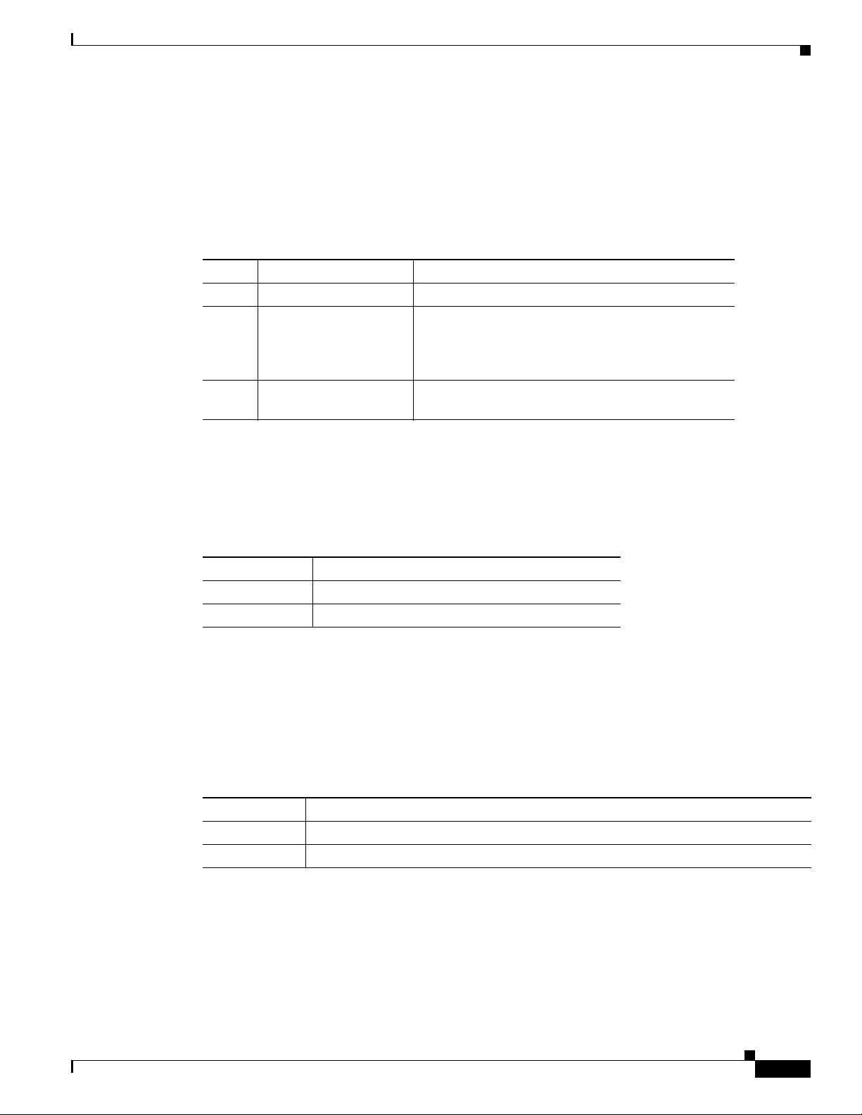
Table 1-1 describes the switch modules.
Ta b l e 1-1 Catalyst Switch Module 3110G, 3110X, and 3012
Switch Model Cisco Part Number IBM Part Number Description
Catalyst Switch
Module 3110G
WS-CBS3110G-S WS-CBS3110G-S-I 4 external 10/100/1000BASE-T
Ethernet ports, 14 internal
1000BASE-X Ethernet downlink ports,
1 internal 100BASE-T Ethernet
management port, 2 StackWise Plus
ports
OL-12192-01
Catalyst Switch Module 3110G, 3110X, and 3012 for IBM BladeCenter Hardware Installation Guide
1-1
Page 8
Hardware Features
201895
C
O
N
S
O
L
E
M
O
D
E
M
B
R
M
S
T
LNK
!
ACT
15
LNK
ACT
16
LNK
ACT
17
LNK
1 ST
A
CK 2
ACT
18
X
2
C
O
N
S
O
L
E
M
O
D
E
M
B
R
M
S
T
!
1 STACK 2
1
4
9
6
5
8
2
7
3
Table 1-1 Catalyst Switch Module 3110G, 3110X, and 3012 (continued)
Switch Model Cisco Part Number IBM Part Number Description
Catalyst Switch
Module 3110X
Catalyst Switch
Module 3012
Hardware Features
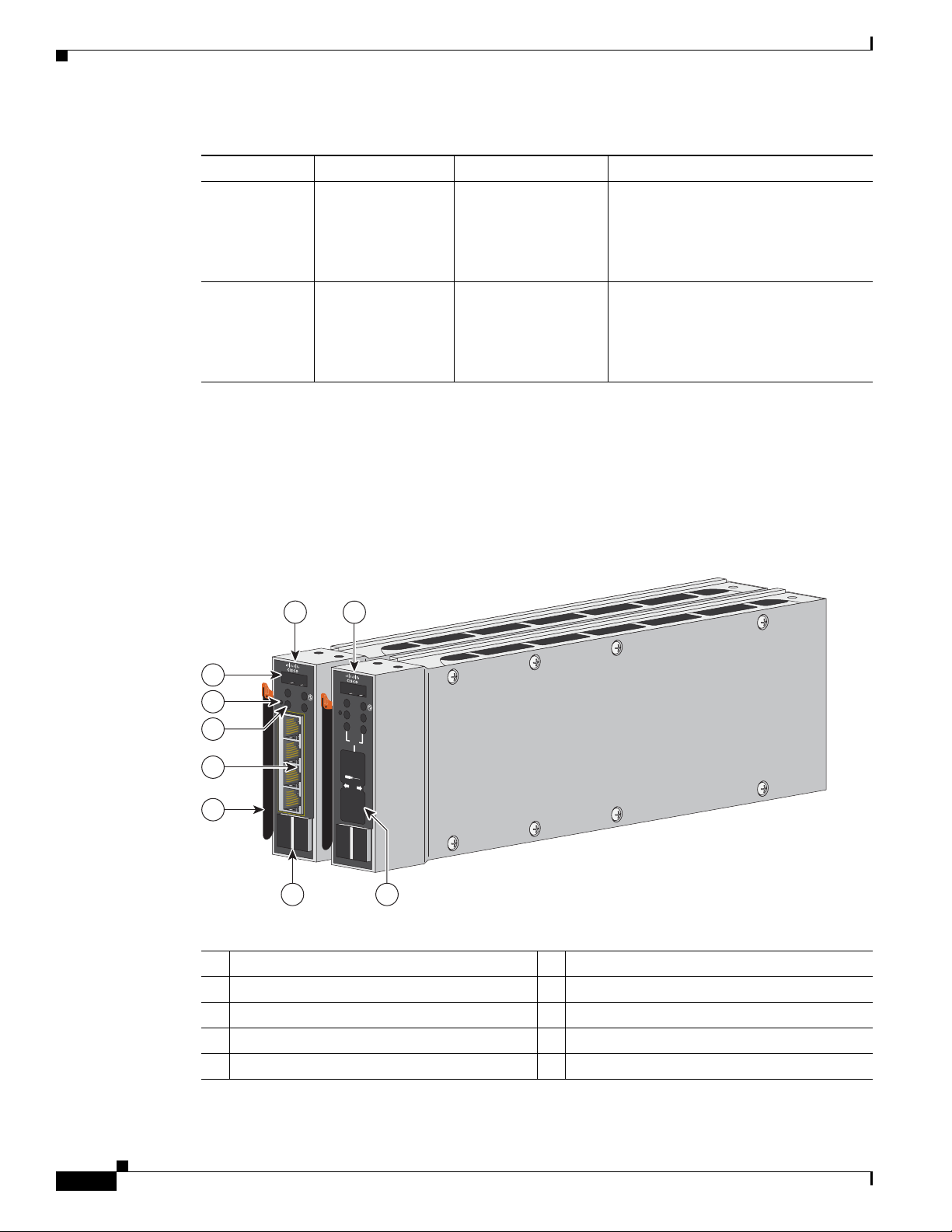
The Catalyst Switch Module 3110G and 3110X include the 10/100/1000 Ethernet ports or the 10-Gigabit
Ethernet module slot, console port, StackWise Plus ports, release latch, and the switch module LEDs
shown in
Figure 1-1 and described on the following pages.
Chapter 1 Product Overview
WS-CBS3110X-S WS-CBS3110X-S-I 1 external 10-Gigabit Ethernet module
slot, 14 internal 1000BASE-X Ethernet
downlink ports, 1 internal 100BASE-T
Ethernet management port, 2
StackWise Plus ports
WS-CBS3012-IBM WS-CBS3012-IBM-I 4 external 10/100/1000BASE-T
Ethernet ports, 14 internal
1000BASE-X Ethernet downlink ports,
1 internal 100BASE-T Ethernet
management port
Figure 1-1 Catalyst Switch Module 3110G and 3110X
1 Catalyst Switch Module 3110G 6 10/100/1000 Ethernet ports
2 Catalyst Switch Module 3110X 7 Switch module LEDs
3 10-Gigabit Ethernet module slot
4 StackWise Plus ports 9 Console port
1
8 Mode button
5 Release latch
1. For use with Cisco X2 transceiver modules.
1-2
Catalyst Switch Module 3110G, 3110X, and 3012 for IBM BladeCenter Hardware Installation Guide
OL-12192-01
Page 9
Chapter 1 Product Overview
270430
C
O
N
S
O
L
E
M
O
D
E
LNK
!
ACT
15
LNK
A
CT
16
LN
K
AC
T
17
LNK
ACT
18
1
2
5
6
3
4
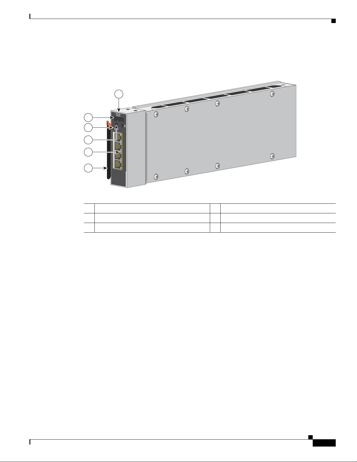
The Catalyst Switch Module 3012 includes the 10/100/1000 Ethernet ports, console port, release latch,
and the switch module LEDs shown in
Figure 1-2 Catalyst Switch Module 3012
Hardware Features
Figure 1-2 and described on the following pages.
1 Catalyst Switch Module 3012 4 Switch module LEDs
2 Console port 5 10/100/1000 Ethernet ports
3 Mode button 6 Release latch
10/100/1000 Ethernet Ports
The Catalyst Switch Module 3110G and 3012 10/100/1000 Ethernet ports use standard RJ-45 connectors
with Ethernet pinouts. The maximum cable length is 328 feet (100 meters). The 100BASE-TX and
1000BASE-T traffic requires Category
cable. The 10BASE-T traffic can use Category 3 or Category 4 UTP cable.
For information about the 10/100/1000 Ethernet port connections and specifications, see the
“Connecting Devices to the Ethernet Ports” section on page 2-13 and Appendix B, “Connector and
Cable Specifications.”
5, Category 5e, or Category 6 unshielded twisted pair (UTP)
OL-12192-01
Catalyst Switch Module 3110G, 3110X, and 3012 for IBM BladeCenter Hardware Installation Guide
1-3
Page 10

Hardware Features
10-Gigabit Ethernet Module Slot
The Catalyst Switch Module 3110X 10-Gigabit Ethernet module slot is used for an uplink connection to
other switches and routers. The module slot operates in full-duplex mode and uses the hot-swappable
Cisco X2 transceiver modules.
The X2 transceiver modules have a dual SC/PC connector (-SR, -LX4) or an Infiniband 4x connector
(-CX4) for connections to multimode fiber (MMF), single-mode fiber (SMF), or 4x
These are the supported Cisco X2 transceiver modules:
• X2-10GB-SR
• X2-10GB-CX4
• X2-10GB-LX4
For information about installing a transceiver module, see the “Installing Devices in the 10-Gigabit
Ethernet Slot” section on page 2-11. For cable specifications, see Appendix B, “Connector and Cable
Specifications.”
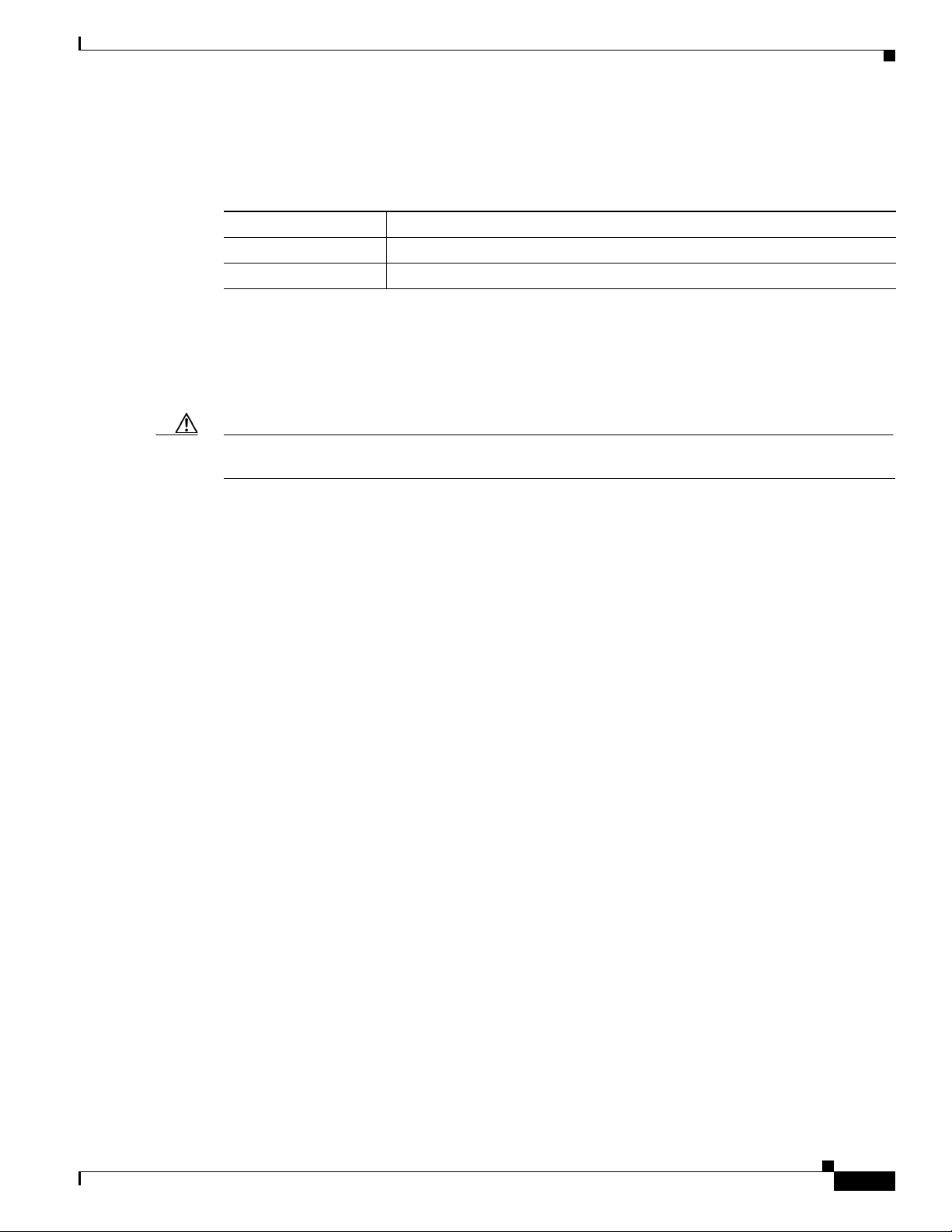
Port Numbering
Chapter 1 Product Overview
Infiniband cable.
Table 1-2 describes the switch module port numbering.
Ta b l e 1-2 Switch Module Port Numbering
Port Description
Ports 1 to 14
Ports 15 to 18 (Catalyst Switch
Module 3110G and 3012)
Port 1 (X2) (Catalyst Switch
Module 3110X)
1. The number of internal ports is determined by the blade enclosure model. See the blade enclosure documentation for more
information about internal port numbering.
1
Internal Gigabit Ethernet 1000BASE-X downlink ports that connect to
the blade enclosure.
External 10/100/1000BASE-T copper Gigabit Ethernet uplink ports.
External 10-Gigabit Ethernet module slot.
Internal 100BASE-T Ethernet Management Port
The internal Ethernet management port (Fa0) is used only for switch module management traffic, not for
data traffic. It is connected to the IBM advanced Management Module (aMM) through the blade
enclosure backplane connector. Traffic to and from this port is isolated from the switch module ports.
This port only supports autonegotiation with 100 Mb/s and full-duplex mode.
1-4
Catalyst Switch Module 3110G, 3110X, and 3012 for IBM BladeCenter Hardware Installation Guide
OL-12192-01
Page 11
Chapter 1 Product Overview
LNK
ACT
LNK
ACT
LNK
ACT
LNK
ACT
201896
C
O
N
S
O
L
E
M
O
D
E
C
O
N
S
O
L
E
M
O
D
E
M
B
R
M
S
T
M
S
T
15
16
17
18
STACK
21
STACK
21
M
B
R
10
6
7
11
9 12
13
8
3 4
2 5
1
X2
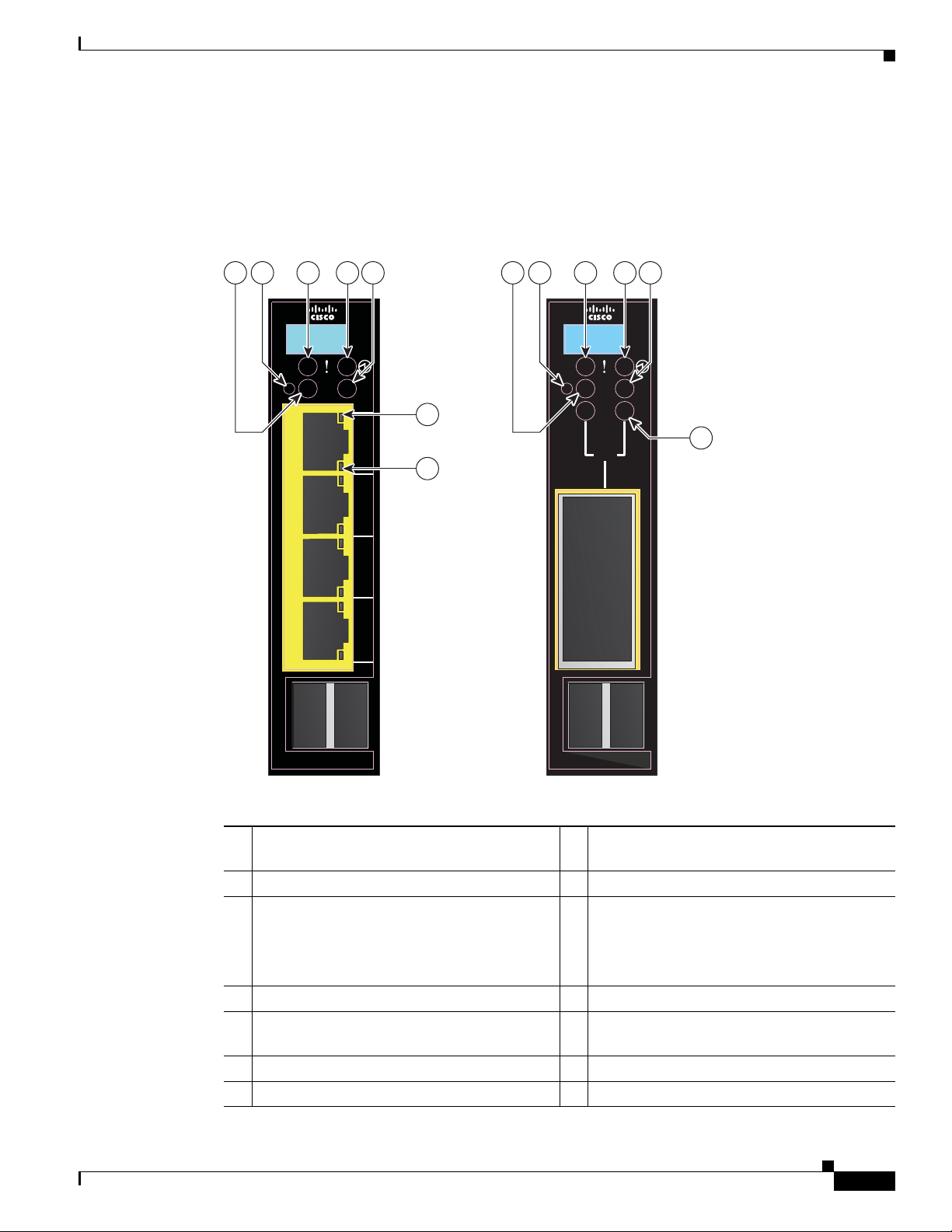
Switch Module LEDs
You can use the switch module LEDs to monitor switch module activity. Figure 1-3 shows the switch
module LEDs and the Mode button that you use to activate the different modes.
Figure 1-3 Switch Module LEDs and Mode Button
Hardware Features
OL-12192-01
8 Stack member LED
10 Fault/stack mode LED
1 Stack member LED
(Catalyst Switch Module 3110G)
2 Mode button 9 Mode button
3 Fault/stack mode LED
(Catalyst Switch Module 3110G)
Fault LED
(Catalyst Switch Module 3012)
4 System power LED 11 System power LED
5 Stack master LED
12 Stack master LED
(Catalyst Switch Module 3110G)
6 Port link LED 13 X2 port status LEDs
7 Port activity LED
Catalyst Switch Module 3110G, 3110X, and 3012 for IBM BladeCenter Hardware Installation Guide
1-5
Page 12
Hardware Features
Mode Button
System Power LED
Chapter 1 Product Overview
The fault/stack or stack member LEDs are selected by using the Mode button. If the mode LED for a
particular mode is solid green, that mode is currently selected, and the other mode LEDs are off (only
Catalyst Switch Module 3110G and 3110X).
To select or change a mode, use a small pointed object to press the Mode button until the desired mode
is selected.
The system power LED shows whether the system is receiving power and is functioning properly.
Table 1-3 lists the LED colors and their meanings.
Ta b l e 1-3 System LED
Color System Status
Off Switch module is not powered on.
Green Switch module is operating normally.
Amber Switch module is receiving power but is not functioning properly.
Blinking green Switch module is running the power-on self-test (POST).
Stack Master LED
The stack master LED shows the stack master status. Tab le 1-4 lists the LED colors and their meanings
(only Catalyst Switch Module 3110G and 3110X).
Ta b l e 1-4 Stack Master LED
Color Description
Off Switch module is not the stack master.
Green Switch module is the stack master or a standalone switch.
Amber An error occurred during stack master election, or another type of
stack error occurred.
1-6
Catalyst Switch Module 3110G, 3110X, and 3012 for IBM BladeCenter Hardware Installation Guide
OL-12192-01
Page 13
Chapter 1 Product Overview
Fault/Stack Mode LED
The fault/stack mode LED shows either a fault condition or the switch stack status, depending on the
Mode button selection. When the switch module is not stacked and there is no fault, the LED is off. If
the switch module is stacked and the stack mode LED is selected, the stack member LED is active.
Table 1-5 lists the LED colors and their meanings (only Catalyst Switch Module 3110G and 3110X).
Ta b l e 1-5 Fault/Stack Mode LED
Color Fault Mode Description Stack Mode Description
Off No switch module faults. Stack mode is not selected.
Green — Switch stack mode is selected. When this LED is
Amber Switch module fault
Hardware Features
green, the stack member LED displays the stack
membership number, and the port LEDs display link
status.
—
detected.
Fault LED
The fault LED shows the switch module fault condition. Tab le 1-6 lists the LED colors and their
meanings (only Catalyst Switch Module 3012).
Ta b l e 1-6 Fault LED
Stack Member LED
The stack member LED is active when the switch module is stacked and you select by using the Mode
button. The stack member LED blinks the number of times equal to the switch stack membership
number.
3110X).
Ta b l e 1-7 Fault/Stack Mode LED
Color Fault Mode Description
Off No switch module faults.
Amber Switch module fault detected.
Table 1-7 lists the LED colors and their meanings (only Catalyst Switch Module 3110G and
Color Description
Off Stack mode is not selected, or the switch module is not stacked.
Blinking green Stack member number.
OL-12192-01
Catalyst Switch Module 3110G, 3110X, and 3012 for IBM BladeCenter Hardware Installation Guide
1-7
Page 14

Hardware Features
Port LEDs
Chapter 1 Product Overview
The Catalyst Switch Module 3110G and 3012 port LEDs show interface activity and link status.
Table 1-8 lists the LED colors and their meanings.
Ta b l e 1-8 Catalyst Switch Module 3110G and 3012 Port LEDs
Color Activity LED Description Link Status LED Description
Off No activity. No link, or port was administratively
shut down.
Green — Link present, or the port might be
blocked by Spanning Tree Protocol
(STP) and is not forwarding data.
Blinking green Activity. Port is sending or receiving
data.
When stack mode is selected on a Catalyst Switch Module 3110G, port 4 activity and link LEDs show
the status for StackWise Plus ports 1 and 2, respectively. The other port LEDs are off.
LED colors and their meanings.
—
Table 1-9 lists the
Ta b l e 1-9 Catalyst Switch Module 3110G Port LEDs with Stack Mode Selected
Color Activity LED Description Link Status LED Description
Off No link. No link.
Green Switch stack link is active. Switch stack link is active.
The Catalyst Switch Module 3110X port status LEDs show interface activity and link status. (The LEDs
combine to display status when an X2 transceiver is inserted.)
Table 1-10 lists the LED colors and their
meanings.
Ta b l e 1-10 Catalyst Switch Module 3110X Port LEDs
Color LED Description
Off No link, or port was administratively shut down.
Green Link present.
Blinking green Activity. Port is sending or receiving data.
Amber Port is blocked by STP and is not forwarding data, or port was
administratively shut down.
Alternating
Link fault.
green-amber
1-8
Catalyst Switch Module 3110G, 3110X, and 3012 for IBM BladeCenter Hardware Installation Guide
OL-12192-01
Page 15
Chapter 1 Product Overview
When stack mode is selected on a Catalyst Switch Module 3110X, the two port status LEDs show the
status for StackWise Plus ports 1 and 2, respectively.
Ta b l e 1-11 Catalyst Switch Module 3110X Port Status LEDs with Stack Mode Selected
Color Port Status LED Description
Off No link.
Green Switch stack link is active.
StackWise Plus Ports
The switch module ships with a 1-meter StackWise Plus cable that you can use to connect the StackWise
Plus ports (only Catalyst Switch Module 3110G and 3110X).
Caution Use only approved cables and connect only to Catalyst Switch Module 3110G and 3110X. Equipment
might be damaged if connected to nonapproved Cisco cables or equipment.
Management Options
Table 1-11 lists the LED colors and their meanings.
You can order these StackWise Plus cables from your supplier:
• CAB-STK-E-0.5M= (0.5-meter cable)
• CAB-STK-E-1M= (1-meter cable)
• CAB-STK-E-3M= (3-meter cable)
Console Port
You can connect the switch module to a host such as a PC, workstation, or a terminal server through the
console port (shown in
to a host.
For more information about the console port, see the switch module getting started guide, the software
configuration guide, and the command reference on Cisco.com.
Management Options
The switch module offers several management options:
• Cisco IOS CLI
The switch module command-line interface (CLI) is based on Cisco IOS software and is enhanced
to support desktop-switching features. You can fully configure and monitor the switch module and
switch stack members from the CLI. You can access the CLI by connecting your management station
directly to the switch module console port or by using Telnet from a remote management station.
See the switch module getting started guide, the software configuration guide, and the command
reference on Cisco.com for more information.
Figure 1-1). Use the supplied USB-to-DB-9 cable to connect the switch module
OL-12192-01
• BladeCenter Advanced Management Module
For standalone switch modules, you can use the aMM to configure the switch module. See the IBM
BladeCenter Advanced Management Module User’s Guide for more information. For stacked
switches, use the CLI to configure and manage the switch stack.
Catalyst Switch Module 3110G, 3110X, and 3012 for IBM BladeCenter Hardware Installation Guide
1-9
Page 16

Management Options
Chapter 1 Product Overview
• IBM Director
For standalone switch modules, you can use the IBM Director to view the hardware configuration
of remote systems, monitor the usage and performance of critical components, centrally manage
individual or large groups of IBM and non-IBM Intel®-processor-based servers, desktop computers,
workstations, and mobile computers on a variety of platforms. See the IBM documentation for more
information.
• Device manager
You can use the device manager, which is in the switch module memory, to manage standalone
switch modules and switch stacks. This web interface offers quick configuration and monitoring.
You can access the device manager from anywhere in your network through a web browser. For more
information, see the getting started guide and the device manager online help.
• Cisco Network Assistant
Cisco Network Assistant is a PC-based network management GUI application optimized for LANs
of small and medium-sized businesses. Cisco Network Assistant offers centralized management of
Cisco switches ranging from the Catalyst Express
GUI, users can configure and manage standalone switch modules and switch stacks. Cisco Network
Assistant is available at no cost and can be downloaded from this URL:
500 through the Cisco Catalyst 4506. Through a
http://www.cisco.com/go/cna_doc
For information on starting the Network Assistant application, see the Getting Started with Cisco
Network Assistant guide on Cisco.com.
• SNMP network management
You can manage switch modules from a SNMP-compatible management station. The switch module
supports a comprehensive set of Management Information Base (MIB) extensions and four Remote
Monitoring (RMON) groups. See the switch module software configuration guide on Cisco.com and
the documentation that came with your SNMP application for more information.
• CiscoWorks application
The CiscoWorks device-management application displays the switch module image that you can use
to set configuration parameters and to view switch module status and performance information. The
CiscoView application, which you purchase separately, can be a standalone application or part of a
Simple Network Management Protocol (SNMP) platform. See the CiscoView documentation for
more information.
Network Configurations
See the switch module software configuration guide on Cisco.com for network configuration concepts
and examples of using the switch module to create dedicated network segments and interconnecting the
segments through Gigabit Ethernet connections.
1-10
Catalyst Switch Module 3110G, 3110X, and 3012 for IBM BladeCenter Hardware Installation Guide
OL-12192-01
Page 17

Switch Module Installation
This chapter describes how to install the Catalyst Switch Module 3110G, 3110X, and 3012 and make
connections to the switch module. It also includes planning and cabling considerations for stacking
switch modules. Read the topics and perform the procedures in this order:
• Preparing for Installation, page 2-1
• Installing the Switch Module, page 2-4
• Creating Switch Stacks, page 2-6
• Installing Devices in the 10-Gigabit Ethernet Slot, page 2-11
• Connecting Devices to the Ethernet Ports, page 2-13
• Where to Go Next, page 2-13
Preparing for Installation
CHA PTER
2
This section covers these topics:
• Safety Warnings, page 2-1
• Installation Guidelines, page 2-3
• Box Contents, page 2-3
Safety Warnings
This section includes the basic installation caution and warning statements. Translations of the warning
statements appear in the Regulatory Compliance and Safety Information for the Cisco Catalyst Switch
Module 3110G, 3110X, and 3012 for IBM BladeCenter that shipped with the switch module and online
at Cisco.com. Read this section before you start the installation procedure.
The switch module is for use only in Listed IBM BladeCenter products. See the switch module release
notes on Cisco.com for Listed IBM BladeCenter products.
Warning
Before working on equipment that is connected to power lines, remove jewelry (including rings,
necklaces, and watches). Metal objects will heat up when connected to power and ground and can
cause serious burns or weld the metal object to the terminals.
Statement 43
OL-12192-01
Catalyst Switch Module 3110G, 3110X, and 3012 for IBM BladeCenter Hardware Installation Guide
2-1
Page 18

Preparing for Installation
Chapter 2 Switch Module Installation
Warning
Warning
Warning
Warning
Warning
Warning
Ethernet cables must be shielded when used in a central office environment.
Statement 171
Do not reach into a vacant slot or chassis while you install or remove a module or a fan. Exposed
circuitry could constitute an energy hazard.
Statement 206
Do not work on the system or connect or disconnect cables during periods of lightning activity.
Statement 1001
Read the installation instructions before connecting the system to the power source.
Class 1 laser product.
Statement 1008
Statement 1004
This unit is intended for installation in restricted access areas. A restricted access area can be
accessed only through the use of a special tool, lock and key, or other means of security.
Statement 1017
Warning
Warning
Warning
Warning
Ultimate disposal of this product should be handled according to all national laws and regulations.
Statement 1040
For connections outside the building where the equipment is installed, the following ports must be
connected through an approved network termination unit with integral circuit protection: 10/100/1000
Ethernet.
Statement 1044
To prevent the system from overheating, do not operate it in an area that exceeds the maximum
recommended ambient temperature of: 131° F (55° C).
Installation of the equipment must comply with local and national electrical codes.
Statement 1047
Statement 1074
2-2
Catalyst Switch Module 3110G, 3110X, and 3012 for IBM BladeCenter Hardware Installation Guide
OL-12192-01
Page 19

Chapter 2 Switch Module Installation
Installation Guidelines
Note This product is not intended to be connected directly or indirectly by any means whatsoever to interfaces
of public telecommunications networks.
Consider these guidelines before you install the switch module:
• Fill any unoccupied interconnect bays or any unoccupied power module bays in the blade enclosure
with filler modules.
• Identify the bays in which you will insert the switch modules. Plan to install the first switch module
in bay 1, the second in bay 2, and so on up to bay 4, if possible.
See the IBM blade enclosure documentation for more information about the specific enclosure
model, the interconnect bay options, and the port mapping between the blade enclosure and the
switch modules.
• For switch stacks, you should first install and configure the switch module that will be the stack
master before installing any additional switch modules. See the
page 2-6 for more information.
• The orange release latch on the switch module means that it is hot-swappable. To maintain proper
system cooling, you must replace a hot-swap switch module within 1 minute of removal.
Preparing for Installation
“Creating Switch Stacks” section on
• Verify that clearance to the switch-module front panel is such that
–
Front-panel indicators can be easily read.
–
Access to ports is sufficient for unrestricted cabling.
–
The X2-10GB-CX4 transceiver-module minimum-bend radius and connector length is met. See
the X2 transceiver module documentation for more information.
• Confirm that cabling is away from sources of electrical noise, such as radios, power lines, and
fluorescent lighting fixtures. Make sure that the cabling is safely away from other devices that might
damage the cables.
• For copper connections on Ethernet ports, cable lengths from the switch module to connected
devices can be up to 328 feet (100
• For cable requirements for X2 module connections, see the “Cable and Adapter Specifications”
meters).
section on page B-2. Each port must match the wave-length specifications on the other end of the
cable, and the cable must not exceed the required cable length.
• Operating environment is within the ranges listed in Appendix A, “Technical Specifications.”
• Review and become familiar with the safety guidelines in the Regulatory Compliance and Safety
Information for the Cisco Catalyst Switch Module 3110G, 3110X, and 3012 for IBM BladeCenter
on the documentation CD.
• Review and become familiar with the safety guidelines, and the temperature, power, and grounding
requirements specified in the IBM blade enclosure installation and user’s guide.
Box Contents
OL-12192-01
The box contents are described in the switch module getting started guide. If any item is missing or
damaged, contact your supplier for support.
Catalyst Switch Module 3110G, 3110X, and 3012 for IBM BladeCenter Hardware Installation Guide
2-3
Page 20

Installing the Switch Module
Installing the Switch Module
This section covers switch module installation. The illustrations in this section show the Catalyst Switch
Module 3110G. The instructions are the same for the Catalyst Switch Module 3110X and 3012.
Follow these steps:
Step 1 Remove the acoustic attenuation module, if one is installed, from the rear of the blade enclosure.
Step 2 Select the blade enclosure bay in which to install the switch module (Figure 2-1).
Note Figure 2-1 shows the IBM BC-H blade enclosure as an example. Your blade enclosure might
look different.
Figure 2-1 Blade Enclosure Rear-Panel View
Chapter 2 Switch Module Installation
1
2
3
4
270428
1 I/O module bay 1 3 I/O module bay 3
2 I/O module bay 2 4 I/O module bay 4
Step 3 Remove the filler module from the selected bay. Store the filler module for future use.
Step 4 If you have not already done so, touch the static-protective package that contains the switch module to
any unpainted metal surface of the blade enclosure or any unpainted metal surface on any other grounded
rack component for at least 2 seconds.
2-4
Step 5 Remove the switch module from its static-protective package.
Step 6 Move the switch module release latch to the open position (perpendicular to the switch module).
Catalyst Switch Module 3110G, 3110X, and 3012 for IBM BladeCenter Hardware Installation Guide
OL-12192-01
Page 21

Chapter 2 Switch Module Installation
C
O
N
S
O
L
E
M
O
D
E
M
B
R
M
S
T
LNK
!
ACT
15
LNK
ACT
16
LNK
ACT
17
LNK
1
STACK
2
ACT
18
201897
Step 7 Slide the switch module into the bay until it stops (Figure 2-2).
Figure 2-2 Installing the Switch Module
Step 8 Move the switch module release latch to the closed position. After you insert and lock the switch module,
it turns on, and the power-on self-test (POST) runs to verify that the switch module is operating correctly.
The system power LED blinks green while POST is running and then turns solid green when POST is
finished.
Installing the Switch Module
Step 9 Confirm that the switch module system power LED is green. See the “Switch Module LEDs” section on
page 1-5 for more information about the switch module LEDs.
Step 10 Replace the acoustic-attenuation module, if applicable.
To remove the switch module, reverse the installation procedure. Place either another switch module or
a filler module in the blade enclosure bay within 1 minute of removal.
After Installing the Switch Module
After the switch module is installed, you might need to:
• Configure the switch module with the initial configuration. For instructions, see the switch module
getting started guide on the documentation CD and also on Cisco.com.
• Connect the StackWise Plus cables to create a switch stack. See the “Creating Switch Stacks”
section on page 2-6 for more information.
• Connect to the switch-module ports. See the “Installing Devices in the 10-Gigabit Ethernet Slot”
section on page 2-11 and the “Connecting Devices to the Ethernet Ports” section on page 2-13.
OL-12192-01
Catalyst Switch Module 3110G, 3110X, and 3012 for IBM BladeCenter Hardware Installation Guide
2-5
Page 22

Creating Switch Stacks
Creating Switch Stacks
This section is only for Catalyst Switch Module 3110G and 3110X and is optional.
A switch stack is a set of up to nine stacking-capable switch modules that are connected through their
StackWise Plus ports. One switch module controls the operation of the stack and is called the stack
master. The stack master and the other switch modules in the stack are stack members. Layer 2 and
Layer
3 protocols present the entire switch stack as a single entity to the network. When switch modules
are not stacked, each acts as a standalone switch module.
Caution The Catalyst Switch Module 3110G and 3110X do not support switch stacks with other types of blades
switches as members. Combining the switch module with other types of blade switches in a switch stack
might cause the switch module to work improperly or to fail.
Stacking Guidelines
Before you connect the switch modules in a stack, observe these stacking guidelines:
• You should install the stack master switch module and run the initial setup program on that switch
module before you connect the StackWise Plus cables to other stack members. We recommend that
you assign the highest priority value to the switch module that you prefer to be the stack master. This
ensures that the switch module is re-elected as stack master if a re-election occurs. As you add new
switch modules to the stack, they automatically become stack members.
Chapter 2 Switch Module Installation
• When you connect the StackWise Plus cables and create a stack, only the status of the stack master
Fa0 interface appears in the switch module configuration, and it shows that the port is shut down
while in stack mode.
• You can stack a combination of up to nine switch modules. You can stack only the Catalyst Switch
Modules 3110G and 3110X; other blade switches are not supported.
• Although the StackWise Plus ports are numbered (1 and 2), you do not need to make specific port
connections between switch modules.
• For conditions that might cause a stack master re-election and for general concepts and procedures
to manage switch stacks, see the “Managing Switch Stacks” chapter in the switch module software
configuration guide on Cisco.com.
• Before connecting, verify the StackWise Plus cable length. Depending on your configuration, you
might need different sized cables. If you do not specify the length of the StackWise Plus cable when
you order your product, the 1-meter cable is supplied. If you need the 0.5-meter cable or the 3-meter
cable, you can order these StackWise Plus cables from your supplier:
–
CAB-STK-E-0.5M= (0.5-meter cable)
–
CAB-STK-E-1M= (1-meter cable)
–
CAB-STK-E-3M= (3-meter cable)
2-6
Catalyst Switch Module 3110G, 3110X, and 3012 for IBM BladeCenter Hardware Installation Guide
OL-12192-01
Page 23

Chapter 2 Switch Module Installation
C
O
N
S
O
L
E
M
O
D
E
M
B
R
M
S
T
LNK
!
ACT
15
LNK
ACT
16
LNK
ACT
17
LNK
1
STACK
2
ACT
18
201898
Connecting a Switch Stack
Follow these steps:
Step 1 Install the member switch modules if you have not already done so.
Step 2 Remove the dust covers from the StackWise Plus cables, and store them for future use.
Step 3 Verify that cables are aligned as shown in Figure 2-3. (The cables are keyed for correct insertion.)
Figure 2-3 Connecting the StackWise Plus Cables
Creating Switch Stacks
Step 4 Insert the cable into the StackWise Plus port on the front panel of the switch module. Insert the other end
of the cable into the connector of the other switch module.
Always use a Cisco-approved StackWise Plus cable to connect the switch modules.
Caution The new stack-member switch module restarts when you connect the StackWise Plus cables.
Step 5 Configure the member switch modules through the master switch module by using the CLI through the
console port of any stack member.
To remove the StackWise Plus cables, grasp the tab on the cable connector, and gently pull straight out.
When you remove the StackWise Plus cables, replace the dust covers to protect them from dust.
Caution Removing and installing the StackWise Plus cable can shorten its useful life. Do not remove and insert
the cable more often than is absolutely necessary.
OL-12192-01
Catalyst Switch Module 3110G, 3110X, and 3012 for IBM BladeCenter Hardware Installation Guide
2-7
Page 24

Creating Switch Stacks
Switch Stack Cabling Examples
Figure 2-4 is an example of a recommended configuration in which two switch modules create a switch
stack in a single blade enclosure.
Figure 2-4 Stacking Switch Modules in a Single Blade Enclosure to Create One Stack
Chapter 2 Switch Module Installation
2-8
Catalyst Switch Module 3110G, 3110X, and 3012 for IBM BladeCenter Hardware Installation Guide
OL-12192-01
Page 25

Chapter 2 Switch Module Installation
Figure 2-5 is an example of a recommended configuration in which eight switch modules create a switch
stack in eight blade enclosures.
Figure 2-5 Stacking Switch Modules in Blade Enclosures to Create One Stack
Creating Switch Stacks
OL-12192-01
203295
Catalyst Switch Module 3110G, 3110X, and 3012 for IBM BladeCenter Hardware Installation Guide
2-9
Page 26

Creating Switch Stacks
203296
Chapter 2 Switch Module Installation
Figure 2-6 shows an example of a recommended configuration in which eight switch modules create two
separate switch stacks in eight blade enclosures. This configuration provides redundant connections.
Figure 2-6 Stacking Switch Modules in Blade Enclosures to Create Two Stacks
2-10
Catalyst Switch Module 3110G, 3110X, and 3012 for IBM BladeCenter Hardware Installation Guide
OL-12192-01
Page 27

Chapter 2 Switch Module Installation
Installing Devices in the 10-Gigabit Ethernet Slot
Installing Devices in the 10-Gigabit Ethernet Slot
This section describes how to install and remove X2 transceiver modules.
Use only Cisco X2 transceiver modules with the switch modules. Each Cisco module has an internal
serial EEPROM that is encoded with security information. This encoding provides a way for Cisco to
identify and validate that the module meets the requirements for the switch module.
For more information about installing, removing, cabling, and troubleshooting X2 transceiver modules,
see the module documentation that shipped with your device. For module cable specifications, see
Appendix B, “Connector and Cable Specifications.”
Installing an X2 Transceiver Module
When installing an X2 transceiver module, observe these general precautions:
• Do not remove the module slot cover from the 10-Gigabit Ethernet slot until you are ready to install
an X2 transceiver. Either a module or the module slot cover must be installed in the slot at all times.
• Do not remove the dust plugs from the fiber-optic X2 transceiver modules or the rubber caps from
the fiber-optic cable until you are ready to connect the cable. The plugs and caps protect the module
ports and cables from contamination and ambient light.
• Removing and installing an X2 module can shorten its useful life. Do not remove and insert any X2
module more often than is absolutely necessary.
• To prevent ESD damage, follow your normal board and component handling procedures when
connecting cables to the switch module and other devices.
To install an X2 transceiver module, follow these steps:
Step 1 Attach an ESD-preventive wrist strap to your wrist and to a bare metal surface.
Step 2 Remove the module from the protective packaging.
Step 3 Remove the 10-Gigabit Ethernet module slot cover and save.
Step 4 Align the transceiver module in the module slot (Figure 2-7).
OL-12192-01
Catalyst Switch Module 3110G, 3110X, and 3012 for IBM BladeCenter Hardware Installation Guide
2-11
Page 28

Installing Devices in the 10-Gigabit Ethernet Slot
X
2
C
O
N
S
O
L
E
M
O
D
E
M
B
R
M
S
T
!
1 ST
A
C
K 2
201899
Caution Verify the correct orientation of your module before inserting it into the slot. Incorrect insertion can
damage the module.
Step 5 Slide the transceiver module into the opening until the back of the module faceplate is flush with the
switch module faceplate.
Figure 2-7 Installing an X2 Transceiver Module
Chapter 2 Switch Module Installation
Removing a Module
Step 1 Attach an ESD-preventive wrist strap to your wrist and to a bare metal surface.
Step 2 Disconnect the cables from the module. For fiber-optic modules, install the optical bore dust plugs.
Step 3 Carefully pull on the X2 module sleeve to disengage it from the slot. Grasp the edges of the module, and
Step 4 Reinstall a replacement module or the module slot cover in the 10-Gigabit Ethernet slot.
Step 5 Place the module in an antistatic bag or other protective environment.
Catalyst Switch Module 3110G, 3110X, and 3012 for IBM BladeCenter Hardware Installation Guide
2-12
To remove an X2 transceiver module, follow these steps:
carefully slide it out of the slot.
OL-12192-01
Page 29

Chapter 2 Switch Module Installation
Connecting Devices to the Ethernet Ports
The 10/100/1000 Ethernet ports use standard RJ-45 connectors with Ethernet pinouts. The maximum
cable length is 328 feet (100 meters). The 100BASE-TX and 1000BASE-T traffic requires Category
Category
Caution Category 5e and Category 6 cables can store high levels of static electricity. Always ground the cables
to a suitable and safe earth ground before connecting them to the switch module or other devices.
The autonegotiation feature is enabled by default on the switch module. At this setting, the
switch-module ports configure themselves to operate at the speed of attached device. If the attached
device does not support autonegotiation, you can explicitly set the switch-module port speed and duplex
parameters. To maximize performance, either let the ports autonegotiate both speed and duplex, or set
the port speed and duplex parameters on both ends of the connection.
For simplified cabling, the automatic medium-dependent interface crossover (auto-MDIX) feature is
enabled by default on the switch module. With auto-MDIX enabled, the switch module detects the
required cable type for copper Ethernet connections and configures the interface accordingly. Therefore,
you can use either a crossover or a straight-through cable for connections to a switch-module
10/100/1000 Ethernet port regardless of the type of device on the other end of the connection.
5e, or Category 6 UTP cable. The 10BASE-T traffic can use Category 3 or Category 4 cable.
Connecting Devices to the Ethernet Ports
5,
See the switch module software configuration guide and the command reference on Cisco.com for more
information about enabling or disabling autonegotiation and auto-MDIX.
If auto-MDIX is disabled, use the guidelines in Table 2-1 to select the correct cable for connecting the
switch-module 10/100/1000 Ethernet ports to other devices. See the “Cable and Adapter Specifications”
section on page B-2 for cable-pinout descriptions.
Ta b l e 2-1 Recommended Ethernet Cables (When Auto-MDIX is Disabled)
Device Crossover Cable
Switch module to switch
module
Switch module to hub Ye s No
Switch module to computer or
server
Switch module to router No Yes
Switch module to IP phone No Yes
1. 100BASE-TX and 1000BASE-T traffic requires twisted four-pair, Category 5, Category 5e, or
Category 6 cable. 10BASE-T traffic can use Category 3 or Category 4 cable.
Where to Go Next
1
Straight-Through Cable
Ye s No
No Yes
1
OL-12192-01
If the default configuration is satisfactory, the switch module does not need further configuration. You
can use any of the management options described in the
change the default configuration.
Catalyst Switch Module 3110G, 3110X, and 3012 for IBM BladeCenter Hardware Installation Guide
“Management Options” section on page 1-9 to
2-13
Page 30

Where to Go Next
Chapter 2 Switch Module Installation
2-14
Catalyst Switch Module 3110G, 3110X, and 3012 for IBM BladeCenter Hardware Installation Guide
OL-12192-01
Page 31

Troubleshooting
This chapter describes these switch module troubleshooting topics:
• Diagnosing Problems, page 3-1
• Resetting the Switch Module, page 3-4
• How to Replace a Failed Stack Member, page 3-5
Diagnosing Problems
The LEDs on the front panel provide troubleshooting information about the switch module. They show
POST failures, port-connectivity problems, and fault indications. You can also get information from the
device manager, from the CLI, or from an SNMP workstation. See the switch module software
configuration guide and the command reference guide on Cisco.com or the documentation that came
with your SNMP application for details.
CHA PTER
3
Verify Switch Module POST Results
As the switch module powers on, it begins the power-on self-test (POST), a series of tests that runs
automatically to ensure that the switch module functions properly. It might take several minutes for the
switch module to complete POST. When POST completes successfully, the System LED remains green.
The other LEDs turn off and return to their operating status. If the switch module fails POST, the System
LED is amber.
Note POST failures are usually fatal. Contact your Cisco technical support representative if your switch
module does not pass POST.
Verify Switch Module LEDs
If you have physical access to the switch module, look at the port LEDs for troubleshooting information
about the switch module. See the
LED colors and their meanings.
“Switch Module LEDs” section on page 1-5 for a description of the
OL-12192-01
Catalyst Switch Module 3110G, 3110X, and 3012 for IBM BladeCenter Hardware Installation Guide
3-1
Page 32

Diagnosing Problems
Verify Switch Module Connections
Review this section when troubleshooting switch module connection problems.
Bad or Damaged Cable
Always evaluate the cable for marginal damage or failure. A cable might be just good enough to connect
at the physical layer, but it could corrupt packets as a result of subtle damage to the wiring or connectors.
You can identify this situation because the port has many packet errors or the port constantly flaps (loses
and regains link). You should:
• Inspect or exchange the copper or fiber-optic cable with a known, good cable.
• Look for broken or missing pins on cable connectors.
• Rule out any bad patch panel connections or media convertors between the source and destination.
If possible, bypass the patch panel or eliminate faulty media convertors (fiber-optic-to-copper).
• Try the cable in another port or interface, if possible, to see if the problem follows the cable.
• StackWise Plus cable: remove and inspect the cable and StackWise Plus port for bent pins or
damaged connectors. If the StackWise Plus cable is bad, replace it with a known good cable.
Chapter 3 Troubleshooting
Ethernet and Fiber Cables
Make sure that you have the correct cable type for the connection:
• For Ethernet, use Category 3 copper cable for 10 Mb/s UTP connections. Use Category 5,
Category
• For fiber-optic connectors, verify that you have the correct cable for the distance and port type. Make
sure that the connected device ports both match and use the same type encoding, optical frequency,
and fiber type. For more information about cabling, see the
Module Cable Specifications” section on page B-3.
• For copper connections, determine if a crossover cable was used when a straight-through was
required or the reverse. Enable auto-MDIX on the switch module, or replace the cable. See
for recommended Ethernet cables.
Link Status
Verify that both sides have link. A single broken wire or one shutdown port can cause one side to show
link, but the other side does not have link.
A link LED does not guarantee that the cable is fully functional. The cable might have encountered
physical stress that causes it to function at a marginal level. If the link light for the port does not come on:
• Connect the cable from the switch module to a known good device.
• Make sure that both ends of the cable are connected to the correct ports.
5e, or Category 6 UTP for 10/100 or 10/100/1000 Mb/s connections.
“10-Gigabit Ethernet X2 Transceiver
Table 2-1
3-2
• Verify that both devices have power.
• Verify that you are using the correct cable type. See Appendix B, “Connector and Cable
Specifications” for more information.
• Look for loose connections. Sometimes a cable appears to be seated, but is not. Disconnect the cable,
and then reconnect it.
Catalyst Switch Module 3110G, 3110X, and 3012 for IBM BladeCenter Hardware Installation Guide
OL-12192-01
Page 33

Chapter 3 Troubleshooting
Transceiver Issues
Use only Cisco X2 transceiver modules on the switch module. Each Cisco module has an internal serial
EEPROM that is encoded with security information. This encoding provides a way for Cisco to identify
and validate that the module meets the requirements for the switch module. Evaluate these items:
• Bad or wrong X2 transceiver module. Exchange suspect module with known good module. Verify
that the module is supported on this platform. (The switch module release notes on Cisco.com list
the X2 modules that the switch module supports.)
• Use the show interfaces privileged EXEC command to verify the port or module error-disabled,
disabled, or shutdown status. Re-enable the port if needed.
• Make sure that all fiber connections are properly cleaned and securely connected.
• For CX4 module connections, make sure that cable routing does not violate the minimum allowed
cable-bend radius. See the module documentation for specific cabling requirements.
• For LX4 modules, we recommend a mode conditioning patch for MMF applications.
Port and Interface Settings
Diagnosing Problems
An obvious but sometimes overlooked cause of port connectivity failure is a disabled port. Verify that
the port or interface is not disabled or powered down for some reason. If a port or interface is manually
shut down on one side of the link or the other side, the link does not come up until you re-enable the
port. Use the show interfaces privileged EXEC command to verify the port or interface error-disabled,
disabled, or shutdown status on both sides of the connection. If needed, re-enable the port or the
interface.
Ping End Device
Test the end device by pinging from the directly connected switch module first, and then work your way
back port by port, interface by interface, trunk by trunk, until you find the source of the connectivity
issue. Make sure that each switch module can see the end device MAC address in its
Content-Addressable Memory (CAM) table.
Spanning Tree Loops
Spanning Tree Protocol (STP) loops can cause serious performance issues that look like port or interface
problems. In this situation, the switch module bandwidth is used over and over again by the same frames,
leaving little room for legitimate traffic.
Loops can be caused by a unidirectional link. A unidirectional link occurs whenever the traffic sent by
the switch module is received by its neighbor, but the traffic from the neighbor is not received by the
switch module. A broken fiber-optic cable, other cabling, or a port issue could cause this one-way
communication.
OL-12192-01
You can enable UniDirectional Link Detection (UDLD) on the switch module to help identify
difficult-to-find unidirectional link problems. UDLD supports two modes of operation: normal (the
default) and aggressive. In normal mode, UDLD detects unidirectional links due to misconnected
interfaces on fiber-optic connections. In aggressive mode, UDLD also detects unidirectional links due
to one-way traffic on fiber-optic and twisted-pair links and due to misconnected interfaces on fiber-optic
links. For information about enabling UDLD on the switch module, see the “Understanding UDLD”
section in the software configuration guide for this release.
Catalyst Switch Module 3110G, 3110X, and 3012 for IBM BladeCenter Hardware Installation Guide
3-3
Page 34

Resetting the Switch Module
Verify Switch Module Performance
Review this section when troubleshooting switch module performance problems.
Speed, Duplex, and Autonegotiation
If the port statistics show a large amount of alignment errors, frame check sequence (FCS), or
late-collisions errors, this might mean a speed or duplex mismatch.
A common issue with speed and duplex is when the duplex settings are mismatched between two switch
modules, between a switch module and a router, or between the switch module and a workstation or
server. This can happen when manually setting the speed and duplex or from autonegotiation issues
between the two devices. A mismatch occurs under these circumstances:
• A manually set speed or duplex parameter is different from the manually set speed or duplex
parameter on the connected port.
• A port is set to autonegotiate, and the connected port is set to full duplex with no autonegotiation.
To maximize switch module performance and ensure a link, follow one of these guidelines when
changing the settings for duplex and speed:
Chapter 3 Troubleshooting
• Let both ports autonegotiate both speed and duplex.
• Manually set the speed and duplex parameters for the ports on both ends of the connection.
• If a remote device does not autonegotiate, configure the duplex settings on the two ports to match.
The speed parameter can adjust itself even if the connected port does not autonegotiate.
Autonegotiation and Network Interface Cards
Problems sometimes occur between the switch module and third-party network interface cards (NICs).
By default, the switch module ports and interfaces are set to autonegotiate. It is common for devices like
laptops or other devices to be set to autonegotiate as well, yet sometimes autonegotation issues occur.
To troubleshoot autonegotiation problems, try manually setting both sides of the connection. If this does
not solve the problem, there could be a problem with the firmware or software on your NIC. You can
resolve this by upgrading the NIC driver to the latest version available from the manufacture.
Cabling Distance
If the port statistics show excessive FCS, late-collision, or alignment errors, verify that the cable distance
from the switch module to the connected device meets the recommended guidelines. See the
Adapter Specifications” section on page B-2 for cabling guidelines.
Resetting the Switch Module
“Cable and
3-4
For a standalone switch, you can perform these functions by using the AMM web interface:
• Reboot the switch
• Restore factory defaults
• Set or reset the IP address, netmask, and default gateway
• Enable or disable external ports
Catalyst Switch Module 3110G, 3110X, and 3012 for IBM BladeCenter Hardware Installation Guide
OL-12192-01
Page 35

Chapter 3 Troubleshooting
• Enable or disable management through the external ports
• Change configuration
• Change or update firmware
For a switch stack, you can use the CLI to perform the same functions. For more information, see the
switch module software configuration guide and the command reference on Cisco.com.
Using the Mode Button to Reset the Switch Module
You can use the Mode button to reset a standalone switch module.
Caution For a standalone switch module, resetting the switch module deletes the configuration and reboots the
switch module.
For a standalone switch module, use a small pointed object to press and hold the Mode button on the
switch module front panel. The switch module LEDs begin blinking after about 3 seconds. Continue
holding down the Mode button. The LEDs stop blinking after 7 more seconds, and then the switch
module reboots.
How to Replace a Failed Stack Member
The switch module is now unconfigured. You can enter the switch module IP information by following
the procedures described in the switch module getting started guide on Cisco.com,
For switch stacks, pressing and holding the Mode button on a member switch module causes the stack
to reboot. It does not remove the configuration from any member switch.
How to Replace a Failed Stack Member
If you need to replace a failed stack member, you can hot swap or replace the switch module by following
this procedure (only Catalyst 3110 switch modules):
1. Get a replacement switch module that has the same model number as the failed switch module.
2. Disconnect and remove any modules and cable connections.
3. Remove the failed switch module.
4. Install and then connect the replacement switch module to the stack.
If you had manually set the member numbers for any members in the stack, you need to manually
assign the replacement switch module with the same member number as the failed switch module.
To manually assign the member number, see the switch module software configuration guide on
Cisco.com.
5. Make the same Gigabit Ethernet connections on the replacement switch module that were on the
failed switch module.
6. Reinstall any modules and cable connections.
The replacement switch module will have the same configuration for all the interfaces as the failed
switch module and will function the same as the failed switch module.
OL-12192-01
Catalyst Switch Module 3110G, 3110X, and 3012 for IBM BladeCenter Hardware Installation Guide
3-5
Page 36

How to Replace a Failed Stack Member
Chapter 3 Troubleshooting
3-6
Catalyst Switch Module 3110G, 3110X, and 3012 for IBM BladeCenter Hardware Installation Guide
OL-12192-01
Page 37

APPENDIX
A
Technical Specifications
This appendix lists the Catalyst Switch Module 3110G, 3110X, and 3012 technical specifications in
Table A-1 and Tabl e A-2.
Ta b l e A-1 Switch Module Environmental and Physical Specifications
Environmental Ranges
Operating temperature 32 to 131°F (0 to 55°C)
Storage temperature –13 to 158°F (–25 to 70°C)
Relative humidity 10 to 85% (noncondensing)
Operating altitude Up to 10,000 ft (3049 m)
Storage altitude Up to 15,000 ft (4573 m)
Physical Specifications
Weight 2.1 lb (0.95 kg)
Physical Specifications
Dimensions (H x D x W) 1.22 x 4.65 x 10.79 in. (3.1 x 11.8 x 27.4 cm)
OL-12192-01
Ta b l e A-2 Power Specifications
Power Specifications
Maximum power 45 W
Input voltage range and frequency 12 VDC +/- 10%
Input current maximum 3.3 A
Total input BTU 135 Btus per hour, 39.6 W
Catalyst Switch Module 3110G, 3110X, and 3012 for IBM BladeCenter Hardware Installation Guide
A-1
Page 38

Appendix A Technical Specifications
A-2
Catalyst Switch Module 3110G, 3110X, and 3012 for IBM BladeCenter Hardware Installation Guide
OL-12192-01
Page 39

2 3145678Pin Label
1
2
3
4
5
6
7
8
TP0+
TP0-
TP1+
TP2+
TP2-
TP1-
TP3+
TP3-
Connector and Cable Specifications
This appendix describes the cables and adapters that you use to connect the Catalyst Switch
Module 3110G, 3110X, and 3012 to other devices. This appendix includes these sections:
• “Connector Specifications” section on page B-1
• “Cable and Adapter Specifications” section on page B-2
Connector Specifications
These sections describe the connectors used with the switch modules:
• 10/100/1000 Ports, page B-1
• 10-Gigabit Ethernet Module Interface, page B-2
• Console Port, page B-2
APPENDIX
B
10/100/1000 Ports
OL-12192-01
The 10/100/1000 Ethernet ports on switch modules use standard RJ-45 connectors and Ethernet pinouts.
Figure B-1 shows the pinouts.
Figure B-1 10/100/1000 Port Pinouts
Catalyst Switch Module 3110G, 3110X, and 3012 for IBM BladeCenter Hardware Installation Guide
B-1
Page 40

Cable and Adapter Specifications
H8707
Tx Rx
10-Gigabit Ethernet Module Interface
The 10-Gigabit Ethernet optical modules use SC connectors or Infiniband 4x connectors, as shown in
Figure B-2 and Figure B-3.
Figure B-2 10-Gigabit Ethernet Optical Module SC Connector
Figure B-3 10-Gigabit Ethernet Infiniband 4x Connector
Appendix B Connector and Cable Specifications
Console Port
The console port uses a USB connector. The supplied USB-to-DB-9 adapter cable is used to connect the
console port of the switch module to a PC.
Cable and Adapter Specifications
These sections describe the cables and adapters used with the switch module:
• 10-Gigabit Ethernet X2 Transceiver Module Cable Specifications, page B-3
• Four Twisted-Pair Cable Pinouts, page B-4
• Two Twisted-Pair Cable Pinouts, page B-5
• Identifying a Crossover Cable, page B-5
Catalyst Switch Module 3110G, 3110X, and 3012 for IBM BladeCenter Hardware Installation Guide
B-2
OL-12192-01
Page 41

Appendix B Connector and Cable Specifications
Cable and Adapter Specifications
10-Gigabit Ethernet X2 Transceiver Module Cable Specifications
Table B-1 lists the port cabling specifications for the 10-Gigabit Ethernet X2 transceiver modules. Each
port must match the wave-length specifications on the other end of the cable, and for reliable
communications, the cable must not exceed the stipulated cable length.
optical transmit and receive specifications.
Ta b l e B-1 X2 Transceiver Port Cabling Specifications
Modal
X2 Product
Number
Wavelength
(nm)
Cable Type
Core Size
(microns)
X2-10GB-SR 850 MMF 62.5
62.5
50.0
50.0
50.0
X2-10GB-LX4 1310 MMF
1
62.5
50.0
50.0
X2-10GB-CX4 — InfiniBand
— — 49 feet (15 m)
Bandwidth
(MHz/km)
160
200
400
500
2000
500
400
500
(copper)
1. Mode conditioning patch cord is recommended for MMF applications.
Table B-2 lists the transceiver
Maximum Cabling Distance
85 feet (26 m)
108 feet (33 m)
217 feet (66 m)
269 feet (82 m)
984 feet (300 m)
984 feet (300 m)
787 feet (240 m)
984 feet (300 m)
Ta b l e B-2 X2 Transceiver Optical Transmit and Receive Specifications
Transmit and
X2 Product
Number
Transceiver Type
X2-10GB-SR 10GBASE-SR,
850-nm MMF
X2-10GB-LX4 10GBASE-LX4
WWWDM
Transmit Power
(dBm)
–11 (Max)
–7.3 (Min)
Receive Power
(dBm)
–1.0 (Max)
–9.9 (Min)
–0.5 per lane (Max) —–0.5 (Max)
–14.4 per lane
Receive
Wavelength (nm)
840 to 860
Four lanes; overall
range: 1269 to 1356
1300-nm MMF
1. The launch power shall be the lesser of the Class 1 safety limit or the maximum receive power. Class 1 laser requirements
are defined by IEC 60825-1: 2001.
OL-12192-01
Catalyst Switch Module 3110G, 3110X, and 3012 for IBM BladeCenter Hardware Installation Guide
B-3
Page 42

Cable and Adapter Specifications
1 TPO+
2 TPO-
3TP1+
6TP1-
1 TP1+
Switch Router or PC
2 TP1-
3 TPO+
6 TPO-
4TP2+
5TP2-
7TP3+
8TP3-
4 TP3+
5 TP3-
7 TP2+
8 TP2-
65272
Four Twisted-Pair Cable Pinouts
Figure B-4 and Figure B-5 show the schematics of four twisted-pair cables.
Figure B-4 Four Twisted-Pair Straight-Through Cable Schematic
Appendix B Connector and Cable Specifications
Figure B-5 Four Twisted-Pair Crossover Cable Schematic
B-4
Catalyst Switch Module 3110G, 3110X, and 3012 for IBM BladeCenter Hardware Installation Guide
OL-12192-01
Page 43

Appendix B Connector and Cable Specifications
Switch
3 TD+
6 TD–
1 RD+
2 RD–
Router or PC
3 RD+
6 RD–
1 TD+
2 TD–
Switch
3 TD+
6 TD–
1 RD+
2 RD–
Switch
3 TD+
6 TD–
1 RD+
2 RD–
H5579
Pin 1
Pin 8
Pin 1 on one connector and
pin 8 on the other connector
should be the same color.
Two Twisted-Pair Cable Pinouts
Figure B-6 and Figure B-7 show the schematics of two twisted-pair cables.
Figure B-6 Two Twisted-Pair Straight-Through Cable Schematic
Figure B-7 Two Twisted-Pair Crossover Cable Schematic
Cable and Adapter Specifications
Identifying a Crossover Cable
To identify a crossover cable, compare the two modular ends of the cable. Hold the cable ends
side-by-side, with the tab at the back. The wire connected to the pin on the outside of the left plug should
be the same color as the wire connected to the pin on the outside of the right plug. (See
Figure B-8 Identifying a Crossover Cable
Figure B-8.)
OL-12192-01
Catalyst Switch Module 3110G, 3110X, and 3012 for IBM BladeCenter Hardware Installation Guide
B-5
Page 44

Cable and Adapter Specifications
Appendix B Connector and Cable Specifications
B-6
Catalyst Switch Module 3110G, 3110X, and 3012 for IBM BladeCenter Hardware Installation Guide
OL-12192-01
Page 45

INDEX
Numerics
10/100/1000 ports
cable lengths
connecting to 2-13
described 1-3
pinouts B-1
recommended cables 2-13
10-Gigabit Ethernet module slots described 1-4
1-3, 2-13
A
AC power specifications A-1
altitude, operating and storage A-1
autonegotiation
default setting
troubleshooting 3-4
2-13
B
straight-through
four twisted-pair pinout
two twisted-pair pinout B-5
X2 transceiver module B-3
Cisco IOS command-line interface 1-9
Cisco IP Phones, connecting to 2-13
Cisco Network Assistant 1-10
CiscoView 1-10
Class 1 laser warning 2-2
CLI 1-9
code compliance warning 2-2
command-line interface
See CLI
connectors and cables
console port
connectors and cables
described 1-9
crossover cable
See cables
B-1 to B-5
B-4
B-2
BladeCenter Advanced Management Module
described
1-9
C
cable lengths B-2
cables
crossover
four twisted-pair pinout
identifying B-5
two twisted-pair pinout B-5
recommended 2-13
StackWise Plus part numbers 1-9
OL-12192-01
B-4
Catalyst Switch Module 3110G, 3110X, and 3012 for IBM BladeCenter Hardware Installation Guide
D
device manager described 1-10
diagnosing problems 3-1
dimensions A-1
duplex
default setting
troubleshooting 3-4
2-13
E
electrical noise, avoiding 2-3
Ethernet and fiber cable troubleshooting 3-2
IN-1
Page 46

Index
F
front panel
10/100/1000 Ethernet ports
10-Gigabit Ethernet module slots 1-4
clearance 2-3
console port 1-9
LEDs 1-5 to 1-9
StackWise Plus ports 1-9
1-3
H
humidity, relative A-1
I
IBM Director described 1-10
installation
installing the switch module
site requirements 2-3
installing X2 transceiver modules 2-11
2-4
J
jewelry removal warning 2-1
L
LEDs
1-7
fault
fault/stack mode 1-7
front panel 1-5 to 1-9
master 1-6
port 1-8
POST results 3-1
stack member 1-7
system power 1-6
troubleshooting with 3-1
lightning activity warning 2-2
link status troubleshooting 3-2
local and national electrical codes compliance 2-2
M
mode button 1-5
N
noise, electrical 2-3
O
outside connections warning 2-2
P
pinouts
10/100/1000 ports
adapters B-5
crossover cables
four twisted-pair
two twisted-pair B-5
straight-through cables
four twisted-pair
two twisted-pair B-5
port and interface troubleshooting 3-3
port LEDs 1-8
port modes
changing
See also mode button
ports
10/100/1000
1-5
connecting to
described 1-3
pinouts B-1
recommended cables 2-13
B-1
B-4
B-4
2-13
IN-2
Catalyst Switch Module 3110G, 3110X, and 3012 for IBM BladeCenter Hardware Installation Guide
OL-12192-01
Page 47

Index
POST
3-1
LEDs
running at power on 3-1
power connection warning 2-2
power specifications A-1
product disposal warning 2-2
S
safety 2-1
Simple Network Management Protocol
See SNMP
SNMP network management platforms
software switch management 1-9
specifications A-1
speed
default setting
troubleshooting 3-4
StackWise Plus ports 1-9
straight-through cable pinout
four twisted-pair
two twisted-pair B-5
switch modules described 1-1, 1-2
system power LED 1-6
2-13
B-4
1-10
POST 3-1
spanning tree loops 3-3
speed, duplex, and autonegotiation 3-4
switch performance 3-4
transceivers 3-3
with LEDs 3-1
U
USB connector, console port 1-9, B-2
W
warnings
Class 1 laser
code compliance 2-2
connecting outside of building 2-2
connecting the power 2-2
disposal of product 2-2
installation 2-1
lightning activity 2-2
removing jewelry 2-1
weight A-1
2-2
T
technical specifications A-1
Telnet, and accessing the CLI 1-9
temperature, operating A-1
troubleshooting
bad or damaged cable
connection problems 3-2
diagnosing problems 3-1
Ethernet and fiber cables 3-2
link status 3-2
ping end device 3-3
port and interface settings 3-3
OL-12192-01
3-2
X
X2 transceiver modules
described
installing 2-11
removing 2-12
Catalyst Switch Module 3110G, 3110X, and 3012 for IBM BladeCenter Hardware Installation Guide
1-4
IN-3
Page 48

Index
IN-4
Catalyst Switch Module 3110G, 3110X, and 3012 for IBM BladeCenter Hardware Installation Guide
OL-12192-01
 Loading...