

Page 1

Corporate Headquarters
Cisco Systems, Inc.
170 West Tasman Drive
San Jose, CA 95134-1706
USA
http://www.cisco.com
Tel: 408 526-4000
800 553-NETS (6387)
Fax: 408 526-4100
VPN 3002 Hardware Client
Getting Started
Release 3.6
August 2002
Text Part Number: OL-2854-01
Page 2

THE SPECIFICATIONS AND INFORMATION REGARDING THE PRODUCTS IN THIS M ANUAL ARE SUBJECT TO CHA NGE WITHOUT NO TICE. ALL
STATEMENTS, INFORMATION, AND RECOMMENDATIONS IN THIS MANUAL ARE BELIEVED TO BE ACCURATE BUT ARE PRESENTED WITHOUT
WARRANTY OF ANY KIND, EXPRESS OR IMPLIED. USERS MUST TAKE FULL RESPONSI BILITY FOR THEIR APPLICA TION OF ANY PRODUCT S.
THE SOFTWARE LICENSE AND LIMITED WARRANTY FOR THE ACCOMPANYING PRODUCT ARE SET FORT H IN THE INFORMATION PACKET T HAT
SHIPPED WITH THE PRODUCT AND ARE INCORPORATED HEREIN BY THIS REFERENCE. IF YOU ARE UNABLE TO LOCATE THE SOFTWARE LICENSE
OR LIMITED WARRANTY, CONTACT YOUR CISCO REPRESENTATIVE FOR A COPY.
The Cisco implementation of TCP head er compressi on is an adap tation of a program developed by the Universi ty of Ca lifornia, Berk eley (UCB) as part of UCB ’s public
domain version of the UNIX operatin g system. All rights reserved . Copyri ght © 1981 , Rege nts of the Uni versity of Calif ornia.
NOTWITHSTANDING ANY OTHER WARRANTY HEREIN, ALL DOCUMENT FILES AND SOFTWARE OF THE SE SUPPLIERS ARE PROVIDED “AS IS” WITH
ALL FAULTS. CISCO AND THE ABOVE-NAMED SUPPLIERS DISCLAI M ALL WARRANTIE S, EXPRESSED OR IMPLIED, INCLUDING, WITHOUT
LIMITATION, THOSE OF MERCHANTABILITY, FITNESS FOR A PARTICULAR PURPOSE AND NO NINFRINGEM ENT OR ARISING FROM A COURS E OF
DEALING, USAGE, OR TRADE PRACTICE.
IN NO EVENT SHALL CISCO OR ITS SUPPLIERS BE LIABLE FOR ANY INDIRECT, SPECIAL, CONSEQUENTIAL, OR INCIDENTAL DAMAGES, INCLUDING ,
WITHOUT LIMITATION, LOST PROFITS OR LOSS OR DAMAGE TO DATA ARISING OUT OF THE USE OR INABILITY TO USE THIS MANUAL, EVEN IF CISCO
OR ITS SUPPLIERS HAVE BEEN ADVISED OF THE POSSIBILITY OF SUCH DAMAGE S.
VPN 3002 Hardware Client Getting Started
Copyright © 2002, Cisco Systems, I nc.
All rights reserved.
CCIP, the Cisco Powered Network mark, the Cisco Systems Verified logo, Cisco Unity, Follow Me Browsing, FormShare, Internet Quotient, iQ Breakthrough, iQ Expertise, iQ
FastTrack, the iQ Logo, iQ Net Readiness Scorecard, Networking Academy, ScriptShare, SMARTnet, TransPath, and Voice LAN are trademarks of Cisco Systems, Inc.; Changing
the Way We Work, Live, Play, and Learn, Discover All That’s Possible, The Fastest Way to Increase Your Internet Quotient, and iQuick Study are service marks of Cisco Systems,
Inc.; and Aironet, ASIST, BPX, Catalyst, CCDA, CCDP, CCIE, CCNA, CCNP, Cisco, the Cisco Certified Internetwork Expert logo, Cisco IOS, the Cisco IOS logo, Cisco Press,
Cisco Systems, Cisco Systems Capital, the Cisco Systems logo, Empowering the Internet Generation, Enterprise/Solver, EtherChannel, EtherSwitch, Fast Step, GigaStack, IOS,
IP/TV, LightStream, MGX, MICA, the Networkers logo, Network Registrar, Packet, PIX, Post-Routing, Pre-Routing, RateMUX, Registrar, SlideCast, StrataView Plus, Stratm,
SwitchProbe, TeleRouter, and VCO are registered trademarks of Cisco Systems, Inc. and/or its affiliates in the U.S. and certain other countries.
All other trademarks mentioned in this document or Web site are the property of their respective owners. The use of the word partner does not imply a partnership relationship
between Cisco and any other company. (0203R)
Page 3

iii
VPN 3002 Hardware Client Getting Started
OL-2854-01
CONTENTS
Preface ix
Audience ix
Organization ix
Related Documentation x
VPN 3002 Hardware Client Documentation x
VPN 3000 Series Concentrator Documentatio n x
VPN Client Docu m e ntation xi
Documentation on VPN Software Distribution CDs xi
Other References xi
Conventions xii
Data Formats xiii
Obtaining Documentation xiv
World Wide Web xiv
Documentation CD-ROM xiv
Ordering Documentation xiv
Documentation Feedback xiv
Obtaining Technical Assistance xv
Cisco.com xv
Technical Assistance Center xv
Cisco TAC Web Site xvi
Cisco TAC Escalation Center xvi
CHAPTER
1 Understanding the VPN 3002 Hardware Client 1-1
VPN 3002 Hardware Client or VPN Client Software? 1-1
Hardware Features 1-1
Client Mode and Networ k Extension Mode 1-2
Online Technical Snapshot Explains PAT and Network Extension Modes 1-2
Client Mode (PAT) 1-2
Client Mode with Split Tunneling 1-3
Network Extension Mode 1-3
Network Extension Mode per Group 1-3
Network Extension Mode with Split Tunneling 1-3
IPSec 1-4
IPSec over TCP 1-4
Page 4

Contents
iv
VPN 3002 Hardware Client Getting Started
OL-2854-01
IPSec over NAT-T 1-4
IPSec over UDP 1-5
Additional Software Features 1-5
Interactive Hardware Client Authentication 1-5
Individual User Authentication 1-6
IPSec Backup Servers 1-7
H.323 in PAT Mode 1-9
Notes on H.323 GateKeepers 1-11
RADIUS with Pa ss w o rd Ex pir y 1-11
Load Balancing 1-12
Simple Certificate Enrollment Protocol (SCEP) 1-12
Reset/Restore Monitoring Statistics 1-12
XML Management 1-12
Reverse Route Injection (RRI) 1-12
AES with Diffie-Hellman Group 5 1-13
Management Interf aces 1-13
VPN Software Features Summary 1-14
Physical Specifications 1-15
CHAPTER
2 Installing and Poweri ng Up the VPN 3002 2-1
Preparing to Install 2-1
Configuring and Managing the VPN 3002 2-1
Browser Requirements 2-1
JavaScript and Cookies 2-2
Navigation Toolbar 2-2
Recommended PC Monitor / Display Settings 2-2
Unpacking 2-2
Installing the VPN 3002 2-3
Connecting the PC/Console 2-3
Connecting Network Cables 2-3
Powering Up 2-3
Beginning Quick Configuration 2-4
Quick Configuration Using Default Values 2-5
PAT Mode 2-5
Network Extension Mode 2-5
Quick Configuration Using Nondefault Values 2-6
Page 5

Contents
v
VPN 3002 Hardware Client Getting Started
OL-2854-01
CHAPTER
3 Using the VPN 3002 Hardware Client Manager for Quick Configuration 3-1
Logging into the VPN 3002 Hardware Client Manager 3-1
Starting Quick Configuration 3-3
About Quick Configuration 3-3
Setting the Time and Date 3-4
Uploading an Existing Configuration File 3-5
Configuring the Private Interface 3-6
Configuration | Quick | Private Interface | Address 3-7
Configuration | Quick | Private Interface | DHCP Server 3-7
Configuring the Public Interface 3-9
DHCP 3-10
PPPoE 3-10
Specify an IP address 3-10
Configuring IPSec 3-11
Configuring PAT or Network Extension Mode 3-13
Online Technical Snapshot Explains PAT and Network Extension Modes 3-13
Client Mode (PAT) 3-13
Client Mode with Split Tunneling 3-14
VPN Concentrator Settings Required for PAT 3-14
Network Extension Mode 3-14
Network Extension Mode per Group 3-15
Network Extension Mode with Split Tunneling 3-15
VPN Concentrator Se ttings Required for Network Extension Mode 3-15
Tunnel Initiation 3-16
Tunnel Initiation with Interactive Unit Authentication 3-16
Data Initiation 3-16
Configuring DNS 3-17
Configuring Static Routes 3-18
Adding a Static Route 3-19
Changing admin Password 3-20
Finishing Quick Configuration 3-21
What Next? 3-21
Using Other VPN 3002 Har dware Client Manager Functions 3-22
Understanding the VPN 3002 Hardware Client Mana ger Window 3-23
CHAPTER
4 Using the Command-Line Interface for Quick Configuration 4-1
About Quick Configuration 4-1
Starting Quick Configuration 4-2
Page 6

Contents
vi
VPN 3002 Hardware Client Getting Started
OL-2854-01
Setting the Time and Date 4-3
Uploading Configuration 4-4
Configuring the Private Interface 4-4
Configuring the Public Interface 4-7
Configuring a System Name 4-8
Configuring DHCP 4-8
Configuring PPPoE 4-9
Configuring a Static IP Address 4-10
Configuring IPSec 4-12
Configuring PAT or Network Extension mode 4-13
Client Mode (PAT) 4-13
VPN 3000 Concentrator Settings Required for PAT 4-13
Network Extension Mode 4-14
VPN 3000 Concentrat or Settings Required for Network Extension Mode 4-14
Enabling or Dis a bling PAT 4-14
Configuring DNS 4-15
Configuring Static Routes 4-15
Adding a Static Route 4-15
Deleting a Static Route 4-17
Changing admin Password 4-17
Completing Quick Configuration 4-18
What Next? 4-18
APPENDIX
A Troubleshooting and Sys tem Errors A-1
Files for Troub le sh oo t ing A-1
Event Logs A-1
Crash Dump File A-2
Configuration Files A-2
LED Indicators A-2
VPN 3002 Front LE D s A-2
VPN 3002 Rear LEDs A-3
System Errors A-3
Settings on the VPN Con centrator A-4
VPN 3002 Hardware Client Manager Errors A-5
Invalid Login or Ses sion Timeout A-5
Manager Logs Out A-6
Incorrect Display A-7
Error Message A-7
Page 7

Contents
vii
VPN 3002 Hardware Client Getting Started
OL-2854-01
Not Allowed Message A-8
Not Found A-9
Microsoft Inte rnet Explorer Scr ipt Error: No such in te rf ac e supported A-10
Command-Line Interface Errors A-10
A-10
INDEX
Page 8

Contents
viii
VPN 3002 Hardware Client Getting Started
OL-2854-01
Page 9

ix
VPN 3002 Hardware Client Getting Started
OL-2854-01
Preface
VPN 3002 Hardware Client Getting Start ed provides i nform ation to take you from unpacki ng and
installing the VPN 3002, through configuring the minimal parameters to make it operational (called
Quick Configuration ). You can do Quick Configuratio n fr om a con sol e with the m enu -bas ed
Command-Li ne In t er face, or you can us e the HTML-based VP N 3002 Hardwar e C l ien t Manager with a
browser. This manual describes bot h me thod s, an d we r ecom me nd t he l atte r fo r ea se of us e.
Audience
We assume you are an experienced system administrator or network administrator with appropriate
education and training, who knows how to install, configure, and manage internetworking systems.
However, virtual private networks and VPN devices might be new to you. You should be familiar with
Windows system configuration and management, and you should be familia r with Mi crosoft Internet
Explorer or Ne tsca pe N avigator or Co mmu nic ator browsers.
Organization
This guide is organized as follows:
Chapter Title Description
Chapter 1 Understanding the VPN 3002
Hardware Client
Summarizes th e hardwa re an d soft wa re fe a ture s
and operation.
Chapter 2 Installing and Powering Up
the VPN 3002
Explains how to prepare for, unpack, install, an d
power up the VPN 3002 Hardware Client, and how
to begin quick co nfigurati on. O n ce y ou have
completed the steps in this chapter, you can use
either Chapter 3 or Chapter 4 to complete quick
configuration.
Chapter 3 Using the VPN 3002
Hardware Client Manager for
Quick Configuration
Explains how to compl ete q ui ck c on figurat ion of
the system using the VP N 3 002 Har dware C lient
Manager with a br owser. We recommend this
method.
Page 10

x
VPN 3002 Hardware Client Getting Started
OL-2854-01
Preface
Related Documentation
Related Documentation
Refer to the following do cuments for further inf ormation about Cisco VPN 3000 Series applica tions and
products.
VPN 3002 Hardware Client Documenta tion
The VPN 3002 H ardware Client Reference provides details on all the functions available in the VPN
3002 Hardware Client Manager. This manual is online only.
The VPN 3002 Hardware Client Quick Start card summarizes t he inform ation for qu ick configur ation .
This quick refe renc e c ar d is pr ovided w ith the VPN 3 002 and i s al so available on line.
The VPN 3002 H ardware Client Basic Inf ormati on sticky label summarizes information for quick
configuration. It is provided with the V PN 3002 an d you can a lso print it fro m the onli ne version; you
can affix the label to the VPN 3002.
The HTML interface, called the VPN 3002 Hardware Client Manager, includes online help that you can
access by clicking the Help icon on the toolbar in the Mana ger win dow.
VPN 3000 Series Concentrator Documentation
The VPN 3000 Series Concentrator Reference V olume I: Configuration explains how to start and use the
VPN Concentrator Ma nager. It details the Configuration scr eens and explai ns how to configure your
device beyond the minimal para m eters you set du ring qu ick configurat ion .
The VPN 3000 S erie s C once ntrator Re ference Volume II: Administration and Monitori ng provi des
guidelines for administering and monitoring the VPN Concentrator. It defines and explains all functions
available in the Administration and Monitoring screens of the VPN Concentrator Manager. Appendixes
to this manual provide tro ubles hootin g guidanc e and explai n how to access and use th e altern ate
command-line i n terfa ce .
The HTML interface, called the VPN Concentrator Manager, includes online help that you can access
by clicking the Help icon on the tool bar in t he Ma nage r win dow.
Chapter 4 Using the Comma nd- Line
Interface fo r Qu ick
Configuration
Explains how to compl ete q ui ck c on figurat ion of
the system using the command- line interfac e from
the console or a Telnet or SSH sessi on.
Appendix A Troubleshooting and System
Errors
Describes common errors that might occur while
configuring or using the sys tem, and h ow to
correct them. It also describes all LED indicators
on the VPN 3002.
Chapter Title Description
Page 11

xi
VPN 3002 Hardware Client Getting Started
OL-2854-01
Preface
Related Documentation
VPN Client Documentation
The VPN Client User Guide explains how to install, configure, and use the VPN Client, which lets a
remote client us e th e IPSec tunn eli ng p rotoc ol for sec ure c on ne ction t o a pr ivate network th rou gh the
VPN Concentrator.
The VPN Client Administrator Guide tells how to configure a VPN Concentrator for remote user
connections using t he V PN Clie nt, how to a utom ate r emot e us er pr ofiles, how t o use th e V PN C lie nt
command-line in terface, a nd how to get troublesho oting i nform ation.
Documentation on VPN Software Dis trib ution CDs
The VPN 3000 Series Concentrator and VPN 3002 Hardware Client documentation are provided on the
VPN 3000 Concentrator software distribution CD-ROM in PDF format. The VPN Client documentation
is included on the VPN Client software distribution CD-ROM, also in PDF format. To view the latest
versions on the Cisco web site, click the Support icon on the toolbar at the top of the VPN Concentrator
Manager, Hardware Client Mana ger, or Clie nt wi ndow. To open the docu ment atio n, you n eed Acro ba t
Reader 3.0 or late r; versi on 4. 5 is inclu de d o n t he Ci sco V PN 3 000 Co ncen trat o r s oftwa re d istr ibution
CD-ROM and on the VPN C lient s oft ware d istr ibution CD -ROM.
Other References
Other useful references include:
• Cisco Systems, Dictionary of Interne tworking Terms and Acronyms. Cisco Press: 2001.
• V irtual Private Networking: An Overview. Microsoft Corporation: 1999. (Av ailable from Microsoft
website.)
• www.ietf.org for Internet Engineering Task Force (IETF) Working Group drafts on IP Sec urity
Protocol (IPSec).
• www.whatis.com, a web refer ence sit e w it h d efinitions fo r c omput er, networki ng, and dat a
communication terms.
Page 12

xii
VPN 3002 Hardware Client Getting Started
OL-2854-01
Preface
Conventions
Conventions
This docume nt u s es the f ol lowing conventions:
Notes use the following conventions:
Note Means reader take note. Notes contain helpful suggestions or references to material not
covered in the publication.
Cautions use the following conventions:
Caution Means reader be careful. Cautions alert you to actions or conditions that could result in
equipment damage or lo ss of data.
Convention Description
boldface font Commands and keywords a re in boldface.
italic font Arguments for which you supply values are in ita li cs.
screen font Terminal sessions and information the system displays
are in
screen font.
boldface screen
font
Information you must enter is in boldface screen font.
^ The symbol ^ r epre se nts t he key labe led Con trol —for
example, the key combination ^D in a screen display
means hold down the Control key while you press the D
key.
Page 13

xiii
VPN 3002 Hardware Client Getting Started
OL-2854-01
Preface
Conventions
Data Formats
As you configure and manage the system, enter dat a in the following format s unless the instr uctions
indicate otherwise:
Type of Data Format
IP Addresses IP addresses use 4-byte dotted decimal notation (for example, 192.168.12.34);
as the example indicates, you ca n omit lea ding zeros in a byte position.
Subnet Masks and
Wildcard Masks
Subnet masks use 4-byte dotted de cimal not ation (for example,
255.255.255.0). Wildcard masks use the sam e notati on (for exampl e,
0.0.0.255); as the example illustrates, you can omit leading zeros in a byte
position.
MAC Addresses MAC addresses use 6-byte hexadecimal no tati on (f or exampl e,
00.10.5A.1F.4F.07).
Hostnames Hostnames use legitimate network hostname or end-system name notation (for
example, VPN01). Spaces are not allowed. A hostname must uniquely identify
a specific system on a network.
Text Strings Text strings use upper- and lower-case al phanu meri c cha racte rs. M ost text
strings are case-sensitive (for example, simon and Simon repre sent different
usernames). In most cases, the max imum length of text strings is 48
characters.
Filenames File names on th e VPN 3002 fol low the DOS 8.3 naming co nvention: a
maximum of eight chara cters fo r the name , plus a maxim um of three
characters for an extension. For example, LOG00007.TXT is a legitimate
filename. The VPN 3002 always stores filenam es in upper case.
Port Numbers Port numbers use decimal numbers from 0 to 65535. No commas or spaces are
permitted in a number.
Page 14

xiv
VPN 3002 Hardware Client Getting Started
OL-2854-01
Preface
Obtaining Docume ntation
Obtaining Documentation
These sections explain how to obtain docu mentation from Cisco Syste ms.
World Wide Web
You can access the most c ur rent Cisc o doc um ent ation on the World Wide Web at this URL:
http://www.cisco.com
Translated documentation is available at this URL:
http://www.cisco.com/public/countries_languages.shtml
Documentation CD-ROM
Cisco documentation and additional literature are available in a Cisco Documentation CD-ROM
package, which is shipped with your product. The Documentation CD-ROM is updated monthly and may
be more current than printed documentation. The CD-ROM package is available as a single unit or
through an annual subscription.
Ordering Documentation
You can order Cisco documentation in these ways:
• Registered Cisco.com users (Cisco direct customers) can order Cisco product documentation from
the Networking Produ cts Market Pla ce:
http://www.cisco.com/cgi-bin/order/order_root.pl
• Registered Cisco.com users can order the Documentation CD-ROM through the online Subscription
Store:
http://www.cisco.com/go/subscription
• Nonregistered Cisco.co m u ser s can o rd er docum en tati on th rou gh a l oc al ac count r epre sen tative by
calling Cisco Systems Corpo rate Headqu arter s (Califo rnia, U.S.A. ) at 408 526-7208 or, elsewhere
in North America, by calli ng 800 55 3-NE TS (6387).
Documentation Feedback
You can submit commen ts e lec tron i call y o n C is co.c om. I n the Ci sco D o cume ntat ion ho me p age, cl ick
the Fax or Email option in the “Leave Feedback” section at the bottom of th e page.
You can e-mail your comments t o bug-doc@c isco.com.
You can submit your comments by mail by using the response ca rd beh ind the fr ont cover of your
document or by wri ting t o the fo llowing a ddress:
Cisco Systems
Attn: Document Resour ce Connec tion
170 West Tasman Drive
San Jose, CA 95134- 988 3
Page 15

xv
VPN 3002 Hardware Client Getting Started
OL-2854-01
Preface
Obtaining Technical Assistance
We appreciate yo ur comm ents .
Obtaining Technical Assistanc e
Cisco provides Cisco.com as a starting point for all technical assistance. Customers and partners can
obtain online documentation, troubleshooting tips, and sample configurations from online tools by using
the Cisco T ech nical Assistance Center (TA C) Web Site. Cisco.com re gistered us ers hav e complete ac cess
to the technical support resources on the Cisco TAC Web Site.
Cisco.com
Cisco.com is the foundation of a suite of interactive, networked services that provides immediate, open
access to Cisco information, networking solutions, service s, pr ogram s, a nd resour ce s at any time , from
anywhere in the wor ld.
Cisco.com is a highly int egrated In ternet a pplicat ion and a powerful , easy- to-use t ool that provi des a
broad range of f eat ures an d s er vices to hel p you w it h th ese tasks:
• Streamline business processes and improve productivity
• Resolve technical issues with online support
• Download and te st so ft war e pa ck ag es
• Order Cisco learning m ateri als and me rcha ndise
• Register for online skill assessment, training, and certification programs
If you want to obtain customized information and service, you can self-register on Cisco.com. To access
Cisco.com, go to this URL:
http://www.cisco.com
Technical Assistance Center
The Cisco Technical Assistance Center ( TAC) is av ailab le to all c ustomers who need techni cal assistan ce
with a Cisco product, technology, or solution. Two levels of support are available: the Cisco TAC
Web Site an d t h e C is co TAC Escalation Cen ter.
Cisco TAC inquiries are ca tegorized acc ording to th e urgency of the issue:
• Priority level 4 (P4)—You need information or assistance concerning Cisco product capabilities,
product installation, or basi c product configuration.
• Priority level 3 (P3)—Your network perform ance is degrade d. Network fu nctiona lity is not iceabl y
impaired, but most business operations continue.
• Priority level 2 (P2)—Your production ne twork is severely degraded, affect ing significant asp ects
of business operations. No workar oun d is available.
• Priority leve l 1 (P1)—Your production network is down, and a critical impact to business operations
will occur if se rv ice is n ot r esto re d qui ck ly. No workaround i s available.
The Cisco TAC resource that you choose is based on the prio rity of th e proble m and the co nditions of
service cont rac ts , w h en appl ic ab le .
Page 16

xvi
VPN 3002 Hardware Client Getting Started
OL-2854-01
Preface
Obtaining Technical As sistance
Cisco TAC Web Site
You can use the Cisco TAC Web Site to resolve P3 and P4 issues yourself, saving bot h cost and time.
The site provides around-the-clock access to online tools, knowledge bases, and software. To access the
Cisco TAC Web Si te, go to t his URL:
http://www.cisco.com/tac
All customers, partners, and resellers who have a valid Cisco service contract have complete access to
the technical support resources on the Cisco TAC Web Site. The Cisco TAC Web Site requires a
Cisco.com login I D a nd passwor d. If yo u have a valid servi ce con tra ct but do no t have a login ID or
password, go to this URL to register:
http://www.cisco.com/register/
If you are a Cisco.com registere d user, and you cannot resol ve your tech ni cal issues by using the Cisco
TAC Web Site, you can open a case online by using the TAC Case Open tool at this URL:
http://www.cisco.com/tac/caseopen
If you have Internet access, we recommend that you open P3 and P4 cases through t he Cisco TAC
Web Site.
Cisco TAC Escalation Center
The Cisco TAC Escalation Center addresses priority level 1 or priority level 2 issues. These
classifications are assigned when severe network degradation significantly impacts business operations.
When you contact the TAC Escalation Center with a P1 or P2 problem, a Cisco TAC engineer
automatically opens a case.
To obtain a dir ect or y o f t oll- free C isco TAC telephone numbers for yo ur co unt r y, go to this UR L:
http://www.cisco.com/warp/public/687/Directory/DirTAC.shtml
Before calling, please check with your network operations center to determine the le v el of Cisco suppor t
services to which your company is entitled: for example, SMARTnet, SMARTnet Onsite, or Netwo rk
Supported Accounts (NSA). When you call the center, please have available your service agreement
number and your product se rial numbe r.
Page 17

CHAPTER
1-1
VPN 3002 Hardware Client Getting Started
OL-2854-01
1
Understanding the VPN 3002 Hardware Client
The Cisco VPN 3002 Hardware Client communicates with a VPN 3000 Series Concentrator to create a
virtual private network across a TCP/IP network (such as the Internet). The VPN 3002 requires minimal
configuration, and you can monitor, configure, and upgrade multiple hardware clients at multiple sites
from a central location.
The secure connecti on betwee n the VPN 300 2 and the V PN Concent rator is call ed a tunnel ; it uses the
IP Security (I PSec) pr otoc ol t o negoti ate sec uri ty pa r amete rs, cre ate a nd m anag e tunn els, e ncap sulat e
packets, trans mit or receive th em thr o ugh the tunnel, and unenca ps u late them. It can support a single IP
network.
VPN 3002 Hardware Client or VPN Client Software?
The VPN 3002 Hardware Client provides an alternative to deploying the VPN client softwar e to PCs at
remote locations. Like the software client, the VPN 3002 is located at a remote site, and provides a
secure connection to a VPN Concentrator at a central site. It is important to understand that it is a
hardware client, and th at you configur e i t a s a cl ien t of t he c en tra l-sit e VP N Co nc entr ator, not a s a
site-to-site connection.
Reasons to us e th e V P N 30 02 ra th er t h an th e s o ftwa re c lie nt in cl u de :
• The computers at the re mote site have operating syst ems other th an Windows.
• You do not own, control , or want to support th e PCs at the remo te site. U sing the VPN 3002
eliminates the need to install and maintain software on those computers.
• You have a large number of remote sites to which you connect using VPNs, and you want to manage
those VPNs from a centr al loca tion.
• The VPN 3002 requires mini mal co nfiguration.
Hardware Features
There are two versions of this VPN 3002 Hardware Client:
• The VPN 3002 has one public and one private 10/100BASE-T Ether net inter face.
• The VPN 3002-8E has one public interface and a b ui lt- in 8-port 10/1 00BASE-T Ethernet switch as
its private interface.
Page 18

1-2
VPN 3002 Hardware Client Getting Started
OL-2854-01
Chapter 1 Understanding the VPN 3002 Hardware Client
Client Mode and Network Extension Mode
All systems feature:
• Motorola PowerPC CPU
• SDRAM memory for nor mal oper ation
• Nonvolatile memory for critical system parameters
• Flash memory for file management
• Software-based en crypt ion
• Single power supply
Client Mode and Network Extension Mode
The VPN 3002 works in either of two modes: Client mode or Network Extension mode. Client mode is
the default.
Online Technical Snapshot Explains PAT and Network Extension Modes
A new interactive multimedia piece explains the differences between Client (PAT) mode and Network
Extension mode. To view it, go to this url:
http://www.cisco.com/mm/techsnap/VPN3002_techsnap.html
Your web browser must be equipped with a current version of the Mac romedia Flash Player to view the
content. If you are unsure whether your browser has the most recent version, you may want to download
and install a f ree copy f rom :
http://www.macromedia.com/shockwave/download/index.cgi?P1_Prod_Version=ShockwaveFlash
Client Mode (PAT)
Client mode, also called Port Address Translation (PAT) mode, isolates al l devices on the VPN 30 02
private network from those on th e c orpor ate n etwork. I n PAT mode:
• IPSec encapsulates al l traffic going from the private network of the VP N 3002 to the ne twork(s)
behind the Internet Key Exchange (IKE) peer, that is, the central-site VPN Concentrator.
• PAT mode employs NAT (Network Address Translation). NAT translates the network addresses of
the devices connected to the VPN 3002 private interface to the IP addre ss of the VPN 3 002 public
interface. The central-site VPN Concentrator assigns this address. NAT also keeps track of these
mappings so that it can forwar d repli es to the co rrect device.
All traffic from the private network appears on the network behind the central-si te VPN Con centrator
(the IKE peer) with a single source IP address. This IP address is the one the central-site VPN
Concentrator assigns to the VPN 300 2. The IP addresse s of the comput ers on the VPN 3002 private
network are hidden. You cannot ping or access a d evice on the VPN 3002 private network from outside
of that private network, or directly fro m a device on the pr ivate network at the centr al site.
Page 19

1-3
VPN 3002 Hardware Client Getting Started
OL-2854-01
Chapter 1 Understanding the VPN 3002 Hardware Client
Client Mode and Network Extension Mode
Client Mode with Split Tunneling
You always assig n t he VPN 3002 to a tunnel group on the central-site VPN Concentrator. If you enable
split tunneling for that group, IPSec and PAT are applied to all traffic that travels t hrough the VPN 3002
to networks within the network list for that group b ehind the c entral-si te VPN Concentra tor.
Traffic from the VPN 3002 to any destination other than those within the network list for that group on
the central-site VPN Concentrator travels in the clear without applying IPSec. NAT translates the
network addresses of the devices connected to the VPN 3002 private interface to the assigned IP address
of the public interface and also keeps trac k of these mappings so that it ca n forward replie s to the correct
device.
The network and addresses on the private side of the VPN 3002 ar e hidd en, an d cannot be ac cessed
directly.
Network Extension Mode
Network Extension mode all ows the VPN 3002 to prese nt a single , routab le netwo rk to the remo te
private network over the VPN tunnel. IPSec encapsulates all traffic from the VPN 3002 private network
to networks behind the central -site VPN Con centrat or. PAT does not apply. Therefore, devices behind
the VPN Concentr ato r h ave direct a cce ss to devices on the VP N 3 002 private network over the tu nnel ,
and only over the tunnel, and vice versa. The VPN 3002 must initiate the tunnel, but after the tunnel is
up, either side can initiate data exchange.
In this mode, the central-site VPN Concentrator does not assign an IP address for tunneled traffic (as it
does in Client/PAT mode). The tunnel is terminated with the VPN 3002 private IP address (the assigned
IP address). To use Network Extension mode, you must configure an IP address other than the default of
192.168.10.1 an d d isable PAT.
Network Extension Mode per Group
Software versions 3.6 and later let a network admi nistrat or restric t the use of network extensio n mode.
On the VPN Con cent rat or, you enab le net work extensi on m ode f or V PN 30 02 ha rd ware cli ents o n a
group basis.
Note If you disallow network extension mode, whi ch is the defaul t setting on the VPN Conc ent rator, the
VPN 3002 can conn ec t t o that VP N C onc e ntra tor in PAT mode onl y. In this case, be c are ful th at a ll
VPN 3002s in the group are configur ed for PAT mode. If a VPN 3002 is configur ed to use network
extension mode and the VPN Con cent rat or to whic h it conn ec ts di sall ows network exten sion mo de ,
the VPN 3002 will attempt to connect every 4 seconds, and every attempt will be rejected; this is the
equivalent of denial of serv ice at tack.
Network Extension Mode with Split Tunneling
You always assig n t he VPN 3002 to a tunnel group on the central-site VPN Concentrator. If you enable
split tunneling for that group, IPSec opera tes on all traf fic that tra vels thro ugh the VPN 3002 to networ ks
within the network list for that group behi nd the central- site VPN Conc entrator. PAT doe s not apply.
Page 20

1-4
VPN 3002 Hardware Client Getting Started
OL-2854-01
Chapter 1 Understanding the VPN 3002 Hardware Client
IPSec
Traf f ic fro m the VPN 3002 to an y destinatio n other than those wit hin the netwo rk list on the central- site
VPN Concentrator travels in the clear without applying IPSec. NAT translates the network addresses of
the devices on the VPN 3002 private network to the address of the VPN 3002 public interface. Thus the
network and addresses on the pr ivate side of the VPN 3002 are a ccessibl e over the tunnel, but are
protected from the Internet, that is, they cannot be accessed directly.
IPSec
IPSec is the set of standards tha t enables the VPN 3002 to co nnect t o a central -site VPN Concen trator
over a secure VPN tunnel. Its sec ur ity measur es add ress dat a privacy, integrity, authentication , and key
management, as w e ll as t unn eli ng.
IPSec over TC P
The VPN 3002 supports IPSec over TCP, which encapsulates encrypted data traffic within TCP packets.
IPSec over TCP enables the VPN 3002 to operate in an environment in which standard Encapsulating
Security Protocol (ESP, Protocol 50) or Internet Key Exchange (IKE, UDP 500) cannot function, or can
function only with modification to existing firewall rules. IPSec over TCP encapsulates both the IKE and
IPSec protocols within a TCP packet, and enable s secure tu nnel ing thro ugh both NAT and PAT devices
and firewalls.
Note This feature does not work with proxy-based firewalls.
The VPN 3002 Hardware Client, which supports one tunnel at a time, can connect using standard IPSec,
IPSec over NAT-T, IPSec over TCP, or IPSec over UDP, but only one for the same tunnel.
To use IPSec over TCP, both the VPN 3002 and the VPN Concentrator to which it connects must
• Be running version 3.5 or later software. A VPN 3002 running software earlier than version 3.5 can
connect to a VPN Concentra tor runni ng version 3.5 software and usi ng IPSec over TCP, with the
VPN 3002 using either IPSec or IPSec over UDP.
• Enable IPSe c over TCP.
• Configure the same port for IPSec over TCP on both the VPN 3002 and the VPN Concentrator.
IPSec over NAT- T
NAT-T (NAT Traversal) lets IPSec peers establish a connection through a NAT device. It does this by
encapsulating IPSec traffic in UDP datagrams, using port 4500, thereby providing NAT devices with port
information. NAT-T auto-detects any NAT devices, and only encapsulates IPSec traffic when necessary.
The VPN 3002 hardware clien t suppor ts NAT-T in software version 3.6 and later. It uses NAT-T by
default, and requires no configuration . The VPN 300 2 first attempts NAT-T, a nd then IPSec/ UDP (if
enabled) if a NAT device is not au to -det e cted, a llowing I PSec tr affic to pass th rou gh firewalls tha t
disallow IPSec.
To use NAT-T you must:
• Open port 4500 o n any firewall you have configured in f ron t of a V PN 3 002 .
• Reconfigure any previous IPSec/UDP configura tion using por t 4500 to a differen t port.
Page 21

1-5
VPN 3002 Hardware Client Getting Started
OL-2854-01
Chapter 1 Understanding the VPN 3002 Hardware Client
Additional Software Features
• Select the second or third options for the Fragmentation Policy parameter in the Configuration |
Interfaces | Public screen. These options let traffic travel across NAT devices that do not support IP
fragmentation; they d o n ot i mpe de the op era tion o f NAT devices that do suppor t I P fr a gment at ion.
IPSec over UDP
The VPN 3002 support s User D atagr am Prot ocol (U DP) Ne twork A ddr ess Translatio n/Firewall (NAT)
Transparent IPSec, which encapsulates encrypted data traffic within UDP packets. IPSec over UDP
enables secure transm ission be tween the VPN 3002 Hardwa re Client an d the VPN Conce ntrator at the
central site through a device, such as a firewall, that is performing Network Address Translation (NAT).
The VPN 3002 sen ds ke epal ives freq uent ly, ensuring tha t the ma pping s o n th e NAT device are kept
active.
You do not have to configure thi s feature on th e VPN 3002, but the following requ ireme nts do app ly:
• Both the VPN Concentra tor and th e VPN 3002 m ust be runni ng Release 3.0.3 or hig her software .
• You must configure IPSec over UDP for the group on the VPN Concentrator to which the VPN 3002
belongs. For an example, refer to the VPN 3000 Concentra tor Mana ger, Configuration | User
Management | Groups | IPSec tab (use the VPN Conce ntrat or Manage r Help, or refe r to VPN 3000
Concentrator Series Reference Volume I: Configuration).
Note We do not currently support a topology with multiple VPN 3002 Hardware Clients behind one NAT
device.
Additional Software Features
The VPN 3002 softwa re incl udes t hese fe atu res.
Interactive Hardware Client Authentication
Interactive hardware client authentication prevents users on the VPN 3002 private LAN from accessing
the central site until the VPN 3002 authenticates.
When you enable i nte ract ive hardware clie nt au then tica tio n, the VPN 30 02 does not use a saved
username and password. Instead you must manu ally en ter a valid userna me and password for the VPN
3002 each time you conn ect. When the VPN 3002 initia tes the tunnel, it sends the use rnam e and
password to the VPN Concentra tor to which it co nnects . The VPN Conc entrat or facilita tes
authentication, on either the internal or an external server. If the username and password are valid, the
tunnel is established.
You configure interac tive hardware client aut hentica tion on the VPN Concen trato r, which pushes the
policy to the VPN 3002. For m or e info rma tion an d co nfigurati on instru ct ions , r e fer t o t he “User
Management” chapter of the VPN 300 Series Concentrator Reference Volume 1: Configuration.
Page 22

1-6
VPN 3002 Hardware Client Getting Started
OL-2854-01
Chapter 1 Understanding the VPN 3002 Hardware Client
Additional Software Features
Enabling and Later Disabling Interacti ve Hardwar e Client Aut henti cation
When you enable interactive hardware client authentication for a group, the VPN Concentrator pushes
that policy to the VPN 3002s in the group . If you have previously set a userna me and pass word on the
VPN 3002, the software deletes them from the configuration file. When you try to connect, the software
prompts you for a us erna me a nd passwor d.
If, on the VPN Concentrator, you subsequently disable interactive hardware authentication for the group,
it is enabled lo ca lly o n t h e V PN 300 2, a nd the soft ware cont inue s to pr ompt f or a use rnam e and
password. This lets the VPN 3002 connect, even though it lacks a saved username and password, and the
VPN Concent r ator h as di sa bled i nt e ract ive har dwar e c lie nt au th en tic a tio n.
If you subsequently configur e a usern am e a nd pa ssword ( in t he VPN 300 2 C onfigura tion | Syst em |
Tunneling Protocols | IPSec screen), the feature is disabled, and the prompt no longer displays. The VPN
3002 connects to the VPN Con centrat or using the saved userna me and password.
Individual User Authentication
Individual user authentication protects the central site from access by unauthorized persons on the same
private LAN as the VPN 3002.
When you enable individual user authentication, each user that connects through a VPN 3002 must open
a web browser and manually enter a valid username and password to access the network behind the VPN
Concentrator, even though the tunne l a lre ad y exist s. Th e V PN 30 02 dire cts t he browser to t he p rop er
pages for login. W hen t h e use r successf ully log s i n, the browser displ ays you r default home p age.
Note You cannot use the command-line interface to log in if user authentication is enabled. You must use
a browser.
• If you have a default home page on t h e remote network behind the VPN Concentrator, or direct the
browser to a website on the remote network behind the VPN Concentrator, the VPN 3002 directs the
browser to the proper p ag es for us er login . W he n y ou suc cessfu lly log in, t he br owser disp lays the
page you originally en tered.
• If you try to access resources on the network behind the VPN Concentrator th at are not web-based,
for example, email, the connection will fail until you authenticate.
• To authenticate, you must enter the IP address for the private interface of the VPN 3002 in the
browser Location or Address field. The browser then displays th e login scre en for the V PN 3002.
To authenticate, clic k the Conne ct/Logi n Status button.
• One user can log in for a maximum of four sessions simultaneously.
Page 23

1-7
VPN 3002 Hardware Client Getting Started
OL-2854-01
Chapter 1 Understanding the VPN 3002 Hardware Client
Additional Software Features
Individual users authe nt ic ate acc or ding to t he orde r of au then tic at ion s er vers tha t y ou co nfigure for a
group on the VPN C onc ent rat or.
You co nfigure in dividual u ser a ut hent ic ation on t he V PN Conc e ntrat or, which p ushes th e pol icy to t he
VPN 3002. For more i nfor ma tion a nd configura tio n in struct ions, ref er t o t he “User Management”
chapter of t he VP N 3 000 Seri es Co nc en trator R eference Volume 1: Configuration.
IPSec Backup Servers
IPSec backup servers let a VPN 3002 har dware clien t connec t to the cen tral site wh en its prima ry
central-site VPN C once ntra tor i s un available. You configure backup servers for a VP N 30 02 eit her on
the VPN 3002, or on a group basis at the central-site VPN Concentrator. If you configure backup servers
on the central-site VPN Concentrator, that VPN Concentrator pushes the backup server policy to the
VPN 3002 hardware clients in the group .
Figure 1-1 illustrates how the backup server feature works.
Figure 1-1 Backup Server Implementation
XYZ corporation has large sites in three cities: San Jose, California; Austin, Texas; and Boston,
Massachusetts. The y just opened a re gion al sales of f ice in Far go, Nort h Dako ta. To provide access to the
corporate network from Fargo, they use a VPN 3002 that connects to a VPN 3080 in San Jose (1). If the
VPN 3002 is unable to contac t the corporat e network, Fargo cannot pla ce orders. The IPSec backu p
server feature lets the VPN 3002 connect to one of several sites, in this case using Austin (2) and Boston
(3) as backup servers, in th at order.
The VPN 3002 in Far go first t ries to reach San Jose. If the init ial IKE packet for that connectio n (1) times
out (8 seconds), it t ries to co nnect to Austin (2). Should this negotiation also time out, it tr ies to c onnect
to Boston (3). These attem pts c ontin ue until the VPN 3002 has tried al l se rvers on its backup server list,
to a maximum of 10.
San Jose
VPN 3080
Concentrator
Austin
VPN 3000
Concentrator
Fargo
VPN 3002
Hardware Client
Boston
VPN 3000
Concentrator
68158
1
2
3
Page 24

1-8
VPN 3002 Hardware Client Getting Started
OL-2854-01
Chapter 1 Understanding the VPN 3002 Hardware Client
Additional Software Features
Be aware of the following chara cter isti cs of the ba ckup se rver feat ure:
• If the VPN 3002 cannot connect after trying all backup servers on the list, it does not automatically
retry.
–
In Network Extensio n m ode, t he V PN 3 002 a ttem pt s a n ew co nnecti on aft er 4 se cond s.
–
In Client mode, the VPN 3002 attempts a new connection when the user clicks the Connect Now
button on the Monitoring | System Status screen, or when data passes from the VPN 3002 to the
VPN Concentrator.
• A VPN 3002 mu st c onnec t t o the pr ima ry V PN Co ncent rat or t o download a bac ku p ser ver l ist
configured on the p ri mar y V PN C once ntra t or. If that VPN Co nc entr ato r i s unavailable, and i f t he
VPN 3002 has a previously configured backup server list, it can co nnect to the se rvers on that list.
• It can download a backup server list only from the primary VPN Concen trato r. The VPN 3002
cannot download a backup ser ver list fro m a back up server.
• The VPN Concentrators that you configure as backup servers do not have to be aware of each other.
• If you change the configuration of backup servers, or delete a backup server during an active session
between a VPN 3002 and a backup server, the session continues without adopting that change. New
settings take effect the next time the VPN 3002 connects to its primary VPN Concentrator.
You can configure th e backup ser ver featu re from the primary V PN Concentr ator or the VPN 3002. Fr om
the VPN Concent rator conf igur e backup serv ers on eit her of the Conf igur ation | User Ma nagement | Base
Group or Groups | M ode Configu ratio n scr eens. On the VPN 30 02, c onfigure b acku p se rvers on the
Configuration | System | Tunneling Protoc ols | IPSec scre en.
The list you configure on the VPN 3002 applies only if the option, Use Client Configured List, is set. T o
set this option, go to t he I PSec B ac kup Servers para met er o n the M ode Co nfigurat ion ta b o f th e
Configuration | User Management | Groups | Add/Modify screen of the primary VPN Concentrator to
which the VPN 3002 c on nec ts.
Note The group name, use rnam e, a nd p asswords tha t yo u con figure f or the VP N 3 002 mu st be id en tica l
for the primary V PN C once ntra tor a nd all back up se rvers. A lso, if you re quire int era ctive hardware
client authenticat ion and/ or individual us er authe nticat ion for th e VPN 3002 on t he prima ry VPN
Concentrator, be sure to configure it on backup servers as well.
Page 25

1-9
VPN 3002 Hardware Client Getting Started
OL-2854-01
Chapter 1 Understanding the VPN 3002 Hardware Client
Additional Software Features
H.323 in PAT Mode
H.323 is the packet-based multimedia communications standard written by the ITU. A variety of
applications use this standard to effect real-time audio, video and data communications. It lets the VPN
3002 support Microsoft NetMeeting. Figure 1- 2 is a network diagram that illustrates H.323 services the
VPN 3002 supports. H.323 requ ires no configu ration on th e VPN 3002.
Figure 1-2 H.323 Network Example
78453
Corporate Network
GateKeeper A
(Zone 2)
GateKeeper B
(Zone 1)
ILS
PC 5
Gateway
POTS_1 POTS_2
VPN 3000
Concentrator
VPN 3002_1VPN 3002_2
PC 3
PC 4
PC 1
PC 2
Internet
Page 26

1-10
VPN 3002 Hardware Client Getting Started
OL-2854-01
Chapter 1 Understanding the VPN 3002 Hardware Client
Additional Software Features
The following sections describe H.323 features, referring to Figure 1-2.
H.323 Element Description
NetMeeting Microsoft conferencing and collaboration software. Features include video and
audio conferencing, whiteboard, chat, file transfer, program sharing, and
remote desktop sha ring.
VPN 3002 H.323 servi ce s sup port Ne tMeet ing . PCs 1 , 2, 3, 4 , and 5 a nd
POTS_1 and 2 can communicate using NetMeeting applications. This includes
PC3 communicating with PC 4, and PC1 comm unicati ng with PC2. Any PC
can host a NetMeeting conference.
GateKeeper A Cisco IOS H.323 GateKeeper, for example, a Cisco 2620 router.
GateKeepers provide registratio n, cal l control , and status ma nageme nt for
H.323 endpoints an d gateways.
• GateKeeper service s m ust resid e on t he c or porat e n etwor k.
• Multiple NetMeeting PCs be hin d the sa me V PN 3002 c an si mu ltaneou sly
register and plac e H .323 c alls to on e or mo re Ga teKeep er z one s. For
example, PC 3 an d PC 4 can bo th r egister t o ei ther Ga teKeeper A or
GateKeeper B, and PC3 can r eg iste r to G ateK eep er A a t the sam e ti me th at
PC 4 registers to G ateKeeper B.
• Two or more PCs behind a VPN 3002 that register to a Gat eKeeper can
make or receive simultaneous calls betwe en two or more endp oints. For
example, PC 1 can call PC3 at the same time that a call from PC 2 to PC 4
and PC 5 is in progress.
ILS (Internet
Locator Direct ory
Services)
Microsoft software that uses the LDAP protocol to provide registrat ion and
status manageme nt f or H.3 23 endpo i nts.
• ILS services must reside on th e corpora te network .
• Multiple PCs behind the same VPN 3002 cannot register to an ILS server.
For example, PC 3 and PC 4 cann ot bot h register t o th e same IL S s erver.
PC 1 and PC 4 can both register to the same ILS server.
• ILS registration for NetMeeting on Windows 9x PCs defaults to LDAP port
389, and for Windows 2000 PCs to port 1002. If your ILS server cannot use
port 1002, you need to reconfigure Windows 2000 PCs for LDAP port 389.
Note A PC can reg ister wit h either a GateK eep er or with an ILS s erv er , b ut no t both si multane ously.
Gateway A Cisco IOS H.323 Gateway, for example, a Cisco 3620 router. Gateways let
H.323 devices, in thi s case Ne tMeet ing PCs, c om mu nicat e w ith non- H.32 3
devices, such as POTS phones .
POTS Plain old telephone system. Any PC can initiate a NetMeeting call to a POTS
phone and exchange audi o. However, a POTS phone cannot initiat e a call to a
NetMeeting PC behin d a VPN 3002.
In this example, PCs 1, 2, 3, 4, or 5 can initiat e calls to POTS_1 or POTS_2,
but POTS_1 and POTS_2 can only receive calls.
MCU Multipoint contr ol un i ts. The VP N Conc ent rator H .323 impl eme nta tion doe s
not support MCUs .
H.323 Endpoint A PC running NetMeeting or a n H.323 Gateway.
Page 27

1-11
VPN 3002 Hardware Client Getting Started
OL-2854-01
Chapter 1 Understanding the VPN 3002 Hardware Client
Additional Software Features
Notes on H.323 GateKeepers
Be aware of the following characteristics of NetMeeting GateKeepers.
NetMeeting Displays Names of Previous Meeti ng Caller s
When an H.323 call is disconnecte d, th e Ne tMe etin g ap p lica tion st ill d isplay s th e n ames o f th e m eeti ng
callers in the Cal l w indow. Before you plac e a n ew call, p er for m a H angup op er ati on to re move these
names.
VPN Tunnel Disconnects or a Network Failure Occurs with NetMeeting Active
When a VPN tunnel disconnects without the PC behind the VPN 3002 logging off from the GateKeeper,
problems may occur. This is so whether the VPN session terminates gracefully, or because of a network
failure (NetMeeting PC re boots or VPN 3002 reboot s).
Because of the failure to log off, a registration mismatch may occur between the GateKeeper and the
NetMeeting application. The GateKeeper maintains a NetMeeting registration based on a configurable
inactivity timeout period, with the def ault being one hour . If a PC attempts registr ation after a discon nect
and before the timeout peri od has expired, the G ateKeeper rejec ts the request .
The solutions are two:
1. Log off from the Ga teKeep er befo re d iscon ne cti ng the tu nne l.
2. Set the GateKeeper registration timeout value to a shorter time period. We recommend 15 minutes.
Use the ‘endpoint ttl’ command on the Cisco GateKeeper to set this value.
RADIUS with Password Expiry
RADIUS with password expiry is an IPSec authentication method that you configure for a VPN 3002 on
on the VPN Concentrator to which it conn ects. This optio n lets the VPN Conc entrato r that is attem pting
to authenticate an IPSec client to an external RADIUS server (acting as a proxy to an NT server)
determine when a user’s passwor d has expire d an d p rom pt for a n ew password. B y defa ult, thi s op tion
is disabled.
Enabling this option allows the VPN Concentrator to use MS-CHAP-v2 when authenticating an IPSec
client to an external RADIUS server. That RADIUS server must support both MS-CHAP-v2 and the
Microsoft Ve ndor Specific Attributes. Refer to the documentation for your RADIUS server to verify that
it supports these capabilities.
Because of the use of MS-CHAP-v2, when this option is enabled, the VPN Concentrator can provide
enhanced login failure messages that describe specific error conditions. These conditions are:
• Restricted login hours.
• Account disabled.
• No dialin permission.
• Error changing password.
• Authentication failure.
The “password expi red” message appear s when the user whose password has expired first attempts t o
log in. The other messages appea r only after three unsu ccessful logi n attemp ts.
Note To use RADIUS p as sword expiry wi th a V PN 3002 , you m ust e nabl e i nte ra ctive hardware cl ient
authentication. This feature does not work for individual user authentication.
Page 28

1-12
VPN 3002 Hardware Client Getting Started
OL-2854-01
Chapter 1 Understanding the VPN 3002 Hardware Client
Additional Software Features
Load Balancing
Load balancing l et s y ou distri bute se ssions am ong t wo or mo re V PN C once ntra tors co nnec ted on the
same network to handle remote sessions. Load balancin g directs sessions to the least lo aded de vice, thus
distributin g the load among al l devi ces. It makes ef fici ent use of syste m resources and provides in creased
performance and h ig h availability. Load balancing re quir es no configur ation on t he VPN 300 2.
Simple Certificate Enrollment Protocol (SCEP)
You can enroll and install digital certif icates on the VPN 300 2 automatical ly or manu ally. The automatic
method is a new feature that uses the Simple Certificate Enrollment Protocol (SCEP) to streamline
enrollment and inst allatio n. SCEP is a secure messa ging protoc ol that req uires mi nimal us er
intervention. This method is quicker than enrolling and installing digital certificates manually, but it is
availab le on ly if you are both enrolling wi th a CA th at su ppo rts SCEP an d en rolling via the web. If your
CA does not support SCEP, or if you enroll with digital certificates by a means other than the web (such
as through email or by a diskette), then you cannot u se the automat ic method; you must use the manua l
method.
Reset/Restore Monitoring Statistics
You can now reset and restore statistical data to better note changes in that data. When you click Reset
on a monitoring o r administratio n screen, the sys tem temporarily resets a counte r for the chosen statistics
without affecting the operation of the VPN 3002. You can then view statistical information without
affecting the actual curren t values of the count ers or othe r manage ment session s. The fu nction is like
that of a vehicle’s trip odometer, versus the regular odometer. Click Restore to return to the actual
statistical values.
XML Management
The VPN 3002 now supports an XML-b ased inte rface that lets you use an external manage men t
application.
Cisco management applications, third-party applications tha t manage our products, and customers who
want to manage their de vices using their own inf rastructure can u se this interface. This feature is en abled
by default; you do not have to configure it.
The XML data c an be se nt to or up load ed f rom t he V PN Co ncen trat o r us ing HTT PS, SSH , or sta ndard
file transfer m e ch an is m s su ch as FTP o r TF TP.
Reverse Route Injection (RRI)
You can co nfigure the V PN Concent rator to add rout es to its rou ting tabl e for remote hardware or
software clien ts. Th e VPN Con centrato r can th en a dve rti se these r out es to its private network via RIP or
OSPF. This feature is called reverse route injection (RRI).
For example, with a VPN 3 002 i n ne twork ext ens ion m ode, ne twork extension RRI aut om atic all y add s
hosts on the VPN 3002 private network to the VPN Concentrator’s routing table for distribution by either
RIP or OSPF.
RRI requires no c onfigura tion on the V PN 30 02.
Page 29

1-13
VPN 3002 Hardware Client Getting Started
OL-2854-01
Chapter 1 Understanding the VPN 3002 Hardware Client
Management Interfaces
AES with Diffie-Hellman Group 5
Software version 3.6 adds support for Advanced Encryption Standard (AES), which is more secure than
DES and more efficient than triple DES. AES has 128- , 192-, and 256 -bit key strengths. This software
version also adds support for Diffie-Hellman Group 5. You select an encryption algorithm as part of
IPSec configuration on the VPN Concent rator.
Management Interfaces
The VPN 3002 offers multipl e manage ment inte rfaces. You can use each of these interface s to fully
configure, administ er, and moni tor t he d evice.
• The VPN 3002 Hardware Cl ient Man ager is an HTML -base d interface that let s you mana ge the
system remotely with a standard web browser using one of the following:
–
HTTP connecti ons
–
HTTPS (HTTP over SSL) secure connections
• The VPN 3002 Hardware Cli ent comm and-lin e inter face is a menu- an d comma nd-li ne based
interface that you can use with the local system console or remotely using one of the following:
–
Telnet connections
–
Telnet over SSL secure connecti ons
–
SSH (Secure Shell)
Page 30

1-14
VPN 3002 Hardware Client Getting Started
OL-2854-01
Chapter 1 Understanding the VPN 3002 Hardware Client
VPN Software Features Summary
VPN Software Features Summary
The VPN 3002 incorpo rates the following softwa re feature s:
VPN Feature Description
Tunneling protocols IPSec Protocol. The VPN 3002 uses the IKE and XAUTH protocols for secure
key exchange and authentication, and to create secure VPN tunnels. The VPN
3002 can connect to the VPN Concentrator using standard IPSec, NAT-T,
IPSec over T CP, or IPSec over UD P.
Encryption algorithms
• 56-bit DES (Data Encryption Stan dard)
• 168-bit Triple DES
• 128-, 192-, and 256-bit AES
Authenti cation
algorithms
• HMAC (hashed message au then tic at ion c od ing) wi th M D 5 (me ssa ge
digest 5)
• HMAC with SHA-1 ( sec ur e ha sh al go rit hm )
Key management
• IKE (Internet Key Exchange , formerl y call ed ISAKM P/O akley) with
Diffie-Hellman key technique
Network addressing
support
• DNS (Domain Name System)
• DHCP (Dynamic Host Configuration Protocol )
• PPP over Ethernet (PPPoE)
Certificate authorities
• Baltimore
• Entrust
• Microsoft Windows 2000
• Netscape
• RSA Keon
• VeriSign
Page 31

1-15
VPN 3002 Hardware Client Getting Started
OL-2854-01
Chapter 1 Understanding the VPN 3002 Hardware Client
Physical Specifications
Physical Specifications
The VPN 3002 has the following physical spe cifications:
System administration
• Session monitoring and management
• Backup IPSec servers
• Load balancing
• Software image upda te
• System reset and reboot
• Ping
• Configurable system administrator profiles
• File Management, inc luding TFTP transfe r
• Digital certificate management
Monitoring
• Event logging and notification via system co nsole, syslo g, and SNMP
traps
• SNMP MIB-II suppo rt
• System status
• Session data
• Extensive statistics
VPN Feature Description
Width 8.85 inches (22.48 cm)
Depth 7 inches (17.78 cm)
Height 2.12 inches (5.38 cm)
Weight 2.25 lbs (1.02 kg)
External power
supply
• Input: 100 to 240 VAC a t 50 /60 Hz (aut osensi ng)
• Output: 3.3 v @ 4 amps
Temperature Normal opera ting environmen t, 32
o
to 104oF (0o to 40oC), convection only
Temperature Non-operati n g environmen t, - 4 to 1 49
o
F (-20o to 65oC)
Humidity Normal operating environmen t, 5 to 95%, noncon densi ng
Cabling distance s Approxima tel y 32 8 f eet (100 m ete rs) f rom an ac tive network device
Compliance FCC, E.U., and VCCI Class B
Page 32

1-16
VPN 3002 Hardware Client Getting Started
OL-2854-01
Chapter 1 Understanding the VPN 3002 Hardware Client
Physical Specifications
Page 33

CHAPTER
2-1
VPN 3002 Hardware Client Getting Started
OL-2854-01
2
Installing and Powering Up the VPN 3002
This chapter tells you how to prepare for, unpack, install, and power up the VPN 3002, and how to begin
quick configuration.
Preparing to Install
To install the VPN 3002, you need the following skills:
• Familiarity with Windows configuration and management, and with Mi crosoft Internet Expl orer or
Netscape Navigator browsers.
• Normal computing-equipment power. For maximum protection, we recommend connecting the VPN
3002 to a condi tioned power source or uninterruptible power supply (UPS). B e sure that the power
source provides a r elia ble Ea rth gr ound.
• At least 3 inches (75 mm) of unobstr ucted space on all sides to ac comm odate cool ing intake vents
on the sides and top.
• Standard UTP/STP twisted-pair network cables, Category 5, with RJ-45 8-pin modular connectors.
Cisco supplies two with the system.
• A standard straight-through RJ-45 serial cable with a female DB-9 connector, which Cisco supplies
with the system.
Configuring and Managing the VPN 3002
You ca n co nfigure an d ma nag e t he VPN 3 002 using th e co mmand -l ine int erfac e from t he con sol e or a
Telnet or SSH client. However, for ease of use, we stro ngly re comm e nd using the VP N 3 002 hard ware
Client Manager, which is HTM L-ba se d, fr om a PC a nd browser.
The PC must be able to run the recommended browser. The console can be the same PC that runs the
browser.
Browser Requirements
The VPN Hardware Client Manager requires either Microsoft Internet Explorer version 4.0 or higher, or
Netscape Navigator version 4.5-4.7 or 6.0. For best results, we recommend Internet Explorer. Whatever
browser and version you use, install the latest patches and service packs for it.
Page 34

2-2
VPN 3002 Hardware Client Getting Started
OL-2854-01
Chapter 2 Installing and Powering Up the VP N 3002
Unpacking
JavaScript and Cookies
Be sure JavaScript and Cookies are enabled in the browser. Refer to the documentation for your browser
for instructions.
Navigation Toolbar
Do not use the browser navigation toolbar buttons Back, Forward, or Refresh / Reload with the VPN
3002 Hardware Client Manager unless instructed to do so. To protect access security, clicking Refresh /
Reload automatically l ogs out the Manag er session. Clic king Back or Forward ma y display stal e
Manager screens with incorrect data or settings.
We recommend that you hide the browser navigation tool bar to prevent mistakes wh ile using the V PN
3002 Hardware Client Manager.
Recommended PC Monitor / Display Settings
For ease of use, we recommend setting your monitor or display:
• Desktop area —1024 x 768 pixels or g reate r. Minimum = 80 0 x 6 00 pi xels.
• Color palette—256 colors or highe r.
Unpacking
The VPN 3002 Hardware Client ships with the listed in Table 2-1. Carefully un pa ck yo ur device and
check your contents against this list:
Table 2-1 VPN 3002 Hardware Client Packing List
Quantity Item
1 CVPN 3002
1 Externa l 15 W p ower supply a nd power co rd
1 RJ-45 to RJ-45 console cable (black)
1 RJ45 to DB9 conso le port ad apter
1 RJ45 to DB25 c ons ole port ada pte r
4 Self-adhesive rubber feet
1 Wall mount kit 2 10-16x1 & 2 10 -16 x1.5 scr ews and 2 wa ll an chors
1 Power cord reten tion bra cket and inst ructions
16’ RJ-45 to RJ-4 5 E the rn et cabl e (y el low)
1 VPN 3000 Con centr ator Seri es So ftware CD
1 VPN 30 02 Basic Inform ation label
1 VPN 30 02 Quick Start card
1 VPN Client Software License Agreement
1 VPN 3002 Ha rdware Client Release Notes
1 Export Comp lianc e Informa tion docum ent
Page 35

2-3
VPN 3002 Hardware Client Getting Started
OL-2854-01
Chapter 2 Installing and Powering Up the VPN 3002
Installing the VPN 3002
Installing the VPN 3002
You ca n plac e t he V PN 3002 o n a tabl e o r s hel f , or yo u ca n h an g it on t he wall.
Connecting the PC/Console
Connect the RJ45 str aigh t-t hrough se ria l c able be twe en t he c on sole po rt o n the ba ck o f th e VPN 300 2
and the COM1 or serial port on the PC.
If you are using a PC with a browser to manage the VPN 3002, be sure the PC is conn ected to the same
private LAN as the VPN 3002.
If you are using a PC with a browser to manage the VPN 3002-8E, be sure the PC is connected to a switch
port that is configured on the same private LAN as the V PN 3002- 8E.
Connecting Network Cables
Connect network cables between the Ethernet interface on the back of the VPN 3002 and their respective
public and private network hub, switch, or device.
The interfaces are (left to right):
• Public = the VPN 3002 interface to the public network.
• Private = the VPN 3002 interface to your private network (inte rnal LAN ).
Powering Up
Power up the PC/console and the VPN 3002 in the following sequence:
Step 1 Turn on the PC/console.
Step 2 If you want to use the command-line interface, start a terminal emulator (HyperTerminal) on the PC.
Configure a connection to COM1, with the following port settings:
• 9600 bits per second
• 8 data bits
• No parity
• 1 stop bit
Set the emulator fo r VT10 0 e mul ati on, o r let it au tode tec t t he e mu lat ion type .
Step 3 Plug in the VPN 3002, which turns on the VPN 3002.
Step 4 The LED(s) on the front panel will blink a nd c hange color as the syste m executes diagnostics.
1 Warranty card and product infor mati on packet
1 Hard co py docume ntation ordering flyer
Table 2-1 VPN 3002 Hardware Client Packing List (continued)
Quantity Item
Page 36

2-4
VPN 3002 Hardware Client Getting Started
OL-2854-01
Chapter 2 Installing and Powering Up the VP N 3002
Beginning Quick Configuration
Step 5 Watch for these LEDs on th e VPN 3002 fro nt panel to stabilize and display as fo llows:
• PWR = green when unit is on.
• SYS = flashes amber when unit is performing diagnostics, flashes green until either the DHCP or
PPPoE session is up (if you are using DHCP or PPPoE), and solid green when op erational.
• VPN = green when tunnel is established.
Step 6 Watch for LEDs on the private and public interf ace ports on the back of the device to d i sp lay as f oll ows:
• Green = the interface is connected to the network.
• Flashing amber = data is traveling across the network.
If LEDs that should be green are amber or off, see Appendix A, “Troubleshooting and System Errors.”
Step 7 If connected, the conso le di spla ys in itia liza tio n an d bo ot mes sag es suc h as:
Boot-ROM Initializing...
Boot configured 16 MB of RAM.
...
Loading image ..........
Verifying image checksum ...........
Active image loaded and verified...
Starting loaded image...
Image Loader Initializing...
Decompressing & loading image ............
Verifying image checksum ...........
Active image loaded and verified...
Starting loaded image...
Starting power-up diagnostics...
pSH+ Copyright (c) Integrated Systems, Inc., 1992.
Cisco Systems, Inc./VPN 3002 Hardware Client Version 3.0(REL) Feb 02 2001 09:53:35
Features:
Initializing VPN 3002 Hardware Client ...
Initialization Complete...Waiting for Network...
Login:_
Beginning Quick Configuration
You are now ready to begin quick configuration: configuring minimal parameters to make the VPN 3002
operational. You can use a browser for quick configuration with the VPN 3002 Hardware Client Manager
(see Chapter 3, “Using the VPN 3002 Hardware Client Manager for Quick Configuration”). While you
can use the co nsol e i nste ad ( see Cha pter 4 , “Using the Command-Line Interface for Quick
Configuration”), we recommend using a browser.
Quick configuration consists of these steps:
Step 1 Set the system time, da te, ti me z one, a nd Day light Savings Time (D ST) su ppor t.
Step 2 Optionally upload an already existing configuration file.
Step 3 Configure the VPN 3002 private interface. To use Network Extension mode, you must configure an IP
address other than the defaul t, which is 192.168.1 0.1. For Client mod e, you do no t need to change this
address.
Page 37

2-5
VPN 3002 Hardware Client Getting Started
OL-2854-01
Chapter 2 Installing and Powering Up the VPN 3002
Beginning Quick Configuration
Step 4 Configure the DHCP server to assign IP addresses for PCs locate d on the private network. The default
IP address pool is 192.168.10 .2–192.168.10.128. For Client mo de, you do no t need to mo dify this
parameter.
Step 5 Configure the VPN 3002 public interface, using DHCP, PPPoE, or static address assignment. Note that
the DHCP client is enabled by default on the public interface.
Step 6 Configure the IPSec parameters wit h group an d username s and passwords and th e IP address of t he
central-site VPN Concentrator, also known as the IKE peer.
Step 7 Set the VPN 3002 to use either Client or Network Extension mode. Client mode is enabled by default,
using Port Address Translation (PAT).
Step 8 If you are usi ng DN S, co nfigure loca l I SP D NS i nf orm atio n f or the VP N 3 002 .
Step 9 Configure static routes.
Step 10 Change the admin password for security.
You are don e!
Quick Configuration Using Default Values
The easiest way to conf igure the VPN 3002 is to ac cept default values f or all parameter s that hav e defaul t
values. The next sections on PAT mode and N etwork Ex tensi o n mod e list the i nfo rmat ion yo u n eed i f
you use default values for qui ck c onfigura tio n.
PAT Mode
For PAT mode, if you accept default values for all parameters, yo u need:
• The IKE peer address, which is the public IP address of the VPN Concentrator to which this VPN
3002 connects.
• Group and userna mes a nd pa sswords. The group a nd user name s and pa sswords m ust also be
configured on the VPN Conce ntrator t o which thi s VPN 3002 connect s. On th e centr al-site VP N
Concentrator, see Configuration | Us er M ana gem ent | G ro ups, a nd Configurat ion | User
Management | Users.
Network Extension Mode
For Network Extension mode, if you a ccept defau lt values for all parame ters, you ne ed:
• An IP address for t he V PN 3002 pr ivate interface (s upp lied by your n etwork ad mini stra tor) .
• The IKE peer address, which is the public IP address of the VPN Concentrator to which the VPN
3002 connects.
• Group and userna mes a nd pa sswords. The group a nd user name s and pa sswords m ust also be
configured on the VPN Conce ntrator t o which thi s VPN 3002 connect s. On th e centr al-site VP N
Concentrator, see Configuration | Us er M ana gem ent | G ro ups, a nd Configurat ion | User
Management | Users.
• Disable PAT.
Page 38

2-6
VPN 3002 Hardware Client Getting Started
OL-2854-01
Chapter 2 Installing and Powering Up the VP N 3002
Beginning Quick Configuration
Quick Configuration Using Nondefault Values
Table 2-2 provides the information y ou need to set all the par ameters for quick conf iguration. Write y our
entries here now to save time as you enter data.
Table 2-2 VPN 3002 Quick Configuration Parameters
Parameter Name Information You Need to Enter Your Entries
Upload Config If you want to upload an already existing configuration file, the path
to and name of the file.
Private Interface Both of the following:
• The IP address and subnet mask for the VPN 3002 i n terface to
your private network. The default IP address is 192.168. 10.1.
Note that to use Network Exte nsion mo de , you mu st configure
this private interface IP address to something other than the
default.
• The IP address pool range to assign, if you use DHCP for
address assignment, and you d o n ot w ant to acc ept defaul t
values.
The default rang e is 1 92. 168 .10 .2 t o 192 .168.1 0. 128 . If you
change the IP address for the private interface, the default is
<Private IP address> + 1 to <Private IP address> + 127.
Public Interface One of the following:
• If statically assigned, the IP address, subnet mask, and default
gateway for the VPN 300 2 in terfa ce t o the p ublic ne twor k.
• If you use DHCP t o obtain an IP address, a system name (also
called a hostname).
• If you use PPPoE to connect to a pu bl ic ne twork , a PPPoE
username and password.
IPSec
If you use digita l
certificat es , you
do not need to
enter this
information.
Both of the following:
• The IKE peer address, th at is, th e IP address for the publi c
interface of the central-site VPN Concentrator to which this
VPN 3002 connect s.
• IPSec group names, use rnames, a nd pa sswords. The se mu st
match the group name s, us erna mes, a nd passwo rds configured
on the central-site VPN Concentrator.
PAT If you want to use Network Extension mode, an IP a ddress fo r th e
private interface other than the default.
DNS If you use DNS, both of the f ollowing:
• The IP address of your local Internet Service Provider’s DNS
server.
• The registered Internet domain name to use with DNS (such as
cisco.com), obtained from your Intern et Service Provi der (ISP).
Static Routes If you want to configure one or more static routes, the IP
address(es), su bnet mas k(s) , an d me tri c(s) th at ap ply to the s tati c
route(s), and destin ation ro uter add ress(es).
Page 39

CHAPTER
3-1
VPN 3002 Hardware Client Getting Started
OL-2854-01
3
Using the VPN 3002 Hardware Client Manager for
Quick Configuration
This chapter tells you how to complete quick configuration of the system using the VPN 3002 Hardware
Client Manager.
The VPN 3002 Hardware Cli ent Man ager is an HTML-ba sed con figuration, admini stratio n, and
monitoring system built int o the VP N 30 02. To use it, you need only conn ec t t o t he V PN 3002 usi n g a
PC and browser on the same p rivate network as the VPN 3 002.
As you proceed, refer t o the data you record ed in Table 2-2.
The figures that follow show only the main fram e of the Mana ger wind ow. To use featur es in the othe r
frames, see the "U nd erst and ing the V PN 30 02 H ardwa re Cl ie nt M ana ger Window" secti on .
Logging into the VPN 3002 Hardware Client Manage r
Access and log into the VPN 3002 Hardware Client Manager using these steps:
Step 1 Start the browser. See the "Browser Requirements" section. We recommend using Microsoft Internet
Explorer for best result s. Maxi mize the br owser window for easies t readi ng.
Step 2 With the browser, connect to the IP a ddr ess of t he V PN 3002 on y our pr ivate interface . En t er t he I P
address (for exampl e, 1 92. 168 .10 .1) i n the Add re ss o r Lo ca tio n field. Th e br owser disp lay s the lo gi n
screen.
The Manager displ ays t he V PN 30 02 H ardware Cli ent Ma nage r L og insc reen .
Page 40

3-2
VPN 3002 Hardware Client Getting Started
OL-2854-01
Chapter 3 Using the VPN 3002 Hardware Client Manager for Quick Configuration
Logging into the VPN 3002 Hardware Client Manager
Figure 3 -1 VPN 3002 Hardware Client Login Screen
Step 3 Log in. Entries are case-sensi ti v e, so ty pe them e xa ctly as sho wn . With Microsoft Internet Explorer, you
can click the Tab key to move from field to field; with other browsers, you may have to change fields
with the mouse. If you make a mistake, click the Clear button and start over.
• Click in the Login field and t y pe a dmin . ( Do n ot p re ss Ent er.)
• Click in the Password field and type admin. (T he field shows *****.)
• Click the Login button.
Page 41

3-3
VPN 3002 Hardware Client Getting Started
OL-2854-01
Chapter 3 Us ing the VPN 3002 Hardware Client Manager for Quick Configuration
Starting Quick Configuration
Starting Quick Configuration
The Manager displ ays t he V PN 3002 H ardwa re Cli ent Ma na ger M ai n s cree n.
Figure 3-2 VPN 3002 Hardware Client Manager Main Screen
To start quick configuratio n, clic k the u nderlin ed lin k that says Click here to start Quick Configuration .
The Manager displays the Time and Date screen, whic h is the first of the quick co nfiguration sc reens.
About Quick Configuration
Text entries are case-sensitive; that is, admin and ADMIN are different passwords.
After you make an entry in a field, do not press the keyboard Enter key. Just move the cursor from field
to field. With Microsoft Int erne t E xplor er, you ca n pr ess the Tab key to move from field to field; ot her
browsers may work differently.
On any screen where it appears, click the Back button to return to the previous screen.
Configuration entries tak e ef fec t as soon as you click the Apply or Continue button, and they constitu te
the active or running co nfigurat ion.
The banner across the t op of the screen indicates t he parameter currently displayed, both by showing in
the top line the complete path to that parameter , for exam ple, Conf iguration | Quick | T im e and Date, an d
also by highlighti ng an abbr eviated n am e of t he par a mete r i n the li ne bel ow, such as Time. For
configured paramete rs, t he Ma nage r ad ds a che ckm ar k to the side of i ts abbr eviated n am e.
You can go through the steps of quick configuration as many times as you want , and you do not have to
proceed sequentially. You can also revisit individual parameters. To reach a screen, click either
–
the abbreviated param eter na me a t t he top of th e sc reen .
–
the Back button to return to a previous screen.
Page 42

3-4
VPN 3002 Hardware Client Getting Started
OL-2854-01
Chapter 3 Using the VPN 3002 Hardware Client Manager for Quick Configuration
Setting the Time and Date
If you make a mistak e and see a n Error s creen with th e message, “An error has occurred while attempting
to perform the operati on,” and you return to the screen where you were working, carefully check all your
previous entri es on that screen. The Manager atte mpts to retain valid entr ies, but invalid entries are lo st.
See Appendix A, “Troubleshooting and System E rro rs” for more d eta ils.
Do not use the browser navigation toolbar buttons Back, Forward, or Refresh / Reload with the VPN
3002 Hardware Client Manager unless instructed to do so. To protect access security, clicking Refresh /
Reload automatically l ogs out the Manag er session. Clic king Back or Forward ma y display stal e
Manager screens with in corre ct data or settings. We recommend that you hide th e browser navigation
toolbar to prevent mistakes while using the VPN Hardware Client Ma nager.
Setting the Time and Date
The Manager displays the Configuration | Quick | Time and Date screen.
Figure 3-3 VPN 3002 Configuration | Quick | Time and Date Screen.
This screen lets you set the time and date on this device.
Step 1 The screen shows the curr ent time and date o n the de vice. The v alues in the Ne w Time fields are the time
on the browser PC, but any entries you make apply to the VPN 3002.
–
Use the pull-down menus to make any change s. The fields ar e, in orde r: Hour : Minute :
Second AM/PM Month / Day / Year Time Zone.
–
The time zone selections are offsets in hours relative to Greenwich Mean Time (GMT), which
is the basis for Internet time synchronization. Enter the Year as a four-digit number.
–
T o enable DST Support, check the box. During Daylight-Saving Time (DST), clocks are set one
hour ahead of standard time. Enabling DST support means that the VPN 3002 automatically
adjusts the time zone for DST or standard time. If your system is in a time zone that uses DST,
you must enable DS T sup por t.
Step 2 Click Continue to save your cha nges a nd p roc eed with qui ck c onfiguratio n.
Page 43

3-5
VPN 3002 Hardware Client Getting Started
OL-2854-01
Chapter 3 Us ing the VPN 3002 Hardware Client Manager for Quick Configuration
Uploading an Existing Configuration File
Uploading an Existing Configuration File
The Manager displays the Configuration | Qui ck | Upload Config scre en.
Figure 3-4 VPN 3002 Configuration | Quick | Upload Config Screen
This feature enables you to use HTTP or HTTPS to transfer (upload) configuration files from your PC, or
from a system accessible to your PC, to the VPN 3002 flash memory.
Step 1 If you do not want to upload a configurat ion file, click No, an d cont inue to the next section.
Step 2 To upload an already existing configuration file, click Yes.
The Manager displays the Configuration | Qui ck | Upload Config | Browse screen.
Figure 3 -5 VPN 3002 Configuration | Quick | Upload Config | Browse Screen
.
Step 1 In the Config File fiel d, either en ter the path to or use the Browse button to find the path to and name of
the configuration file you want to upload.
Step 2 Click Upload to use this file as your configuration file, or click Back to return to the Configu ration |
Quick | Upload Config screen.
Page 44

3-6
VPN 3002 Hardware Client Getting Started
OL-2854-01
Chapter 3 Using the VPN 3002 Hardware Client Manager for Quick Configuration
Configurin g the Private Interface
Configuring the Private Interfa ce
The VPN 3002 Configuration | Quic k | Private Interface screen disp lays.
Figure 3-6 Configuration | Quick | Private Interface Screen
This screen lets you configure the VPN 3002 private interface, which is the interface to your private
network (internal LAN).
The screen disp lays the curr ent configu ratio n set ti ngs.
Note For the VPN 3002 t o op era te in N etwork E xt ensi on mod e, yo u must cha ng e th e p rivate interface IP
address from the default of 19 2.168.10. 1.
Caution If you modify any parameters of the interface that you are currently using to connect to the VPN
3002, you will break the conn ection, and you will ha ve to restart the Manager and quick configurati on
from the login screen.
Step 1 To reconfigure the IP address for the private interface, select Yes. The Manager displays the
Configuration | Quick | Private Interface | Address screen . See Figure 3-7 and perform the steps in that
section.
Step 2 T o use the VPN 3002 DHCP server to provide addresses for the local LAN, select one of the Y es options.
If you select Yes, and configure the DHCP server parameters, the Manager displays the Configuration |
Quick | Private Interface | DHCP Server screen. See Figure 3-8 and perform the steps in that section.
Step 3 When you have made your selections, click Continue to apply your changes and proceed. Click Back if
you do not want to save your changes; you return to the Configuration | Quick | Private Interface screen .
Page 45
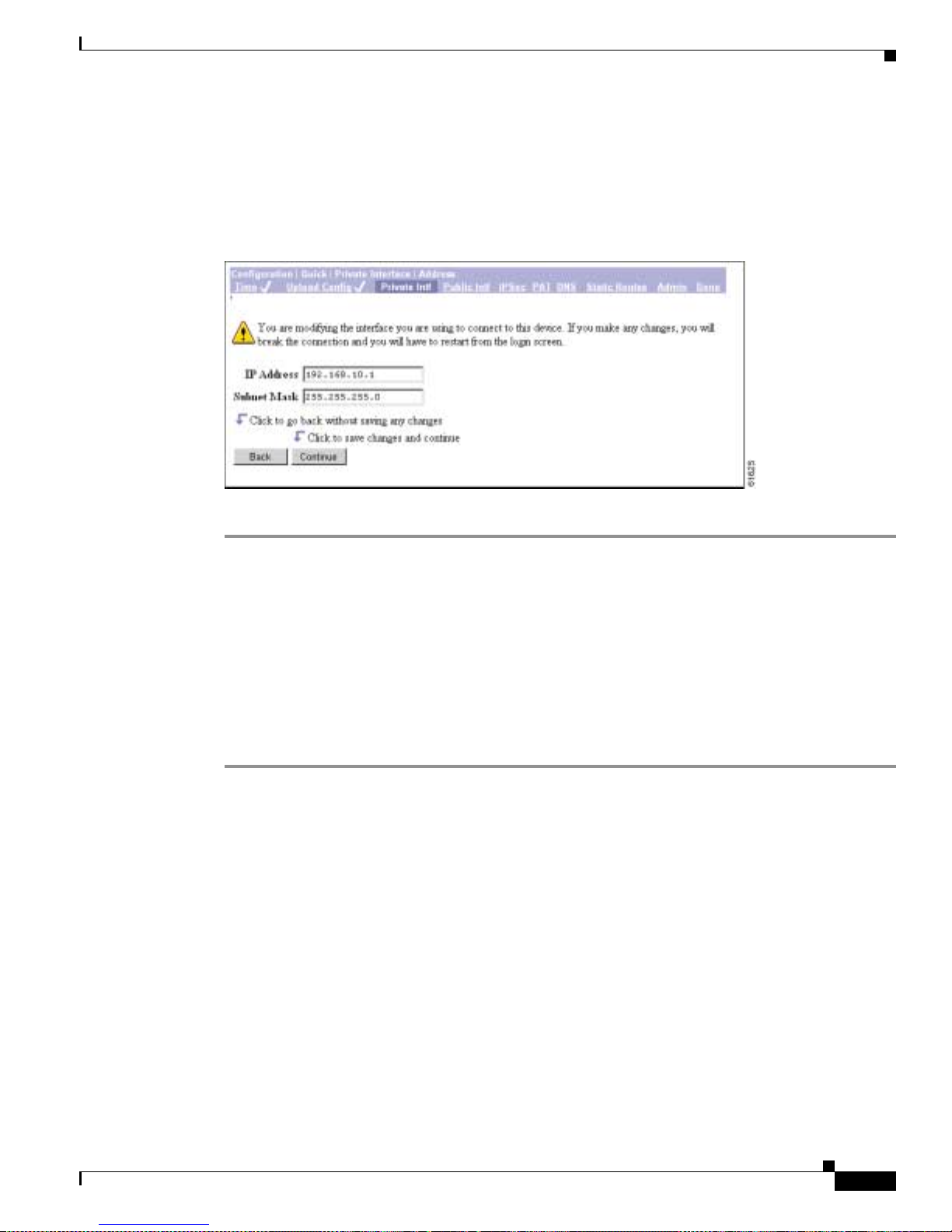
3-7
VPN 3002 Hardware Client Getting Started
OL-2854-01
Chapter 3 Us ing the VPN 3002 Hardware Client Manager for Quick Configuration
Configuring the Private Interface
Configuration | Quick | Private Interface | Address
The Configur ation | Qui ck | Pri v ate Interf ace | Addr ess screen lets you ent er a ne w IP address and subnet
mask for the private interface.
Figure 3-7 Configuration | Quick | Private Interface | Address Screen
Step 1 In the IP Address field, enter the IP address for this interface, using dotted decimal notation (for
example,
192.168.12.34). Be sure no other device is using this address on the network.
Step 2 In the Subnet Mask field, enter the subnet mask for this interface, using dotted decimal notation (for
example,
255.255.255.0). The Manager a utom a ticall y supp lies a stan da rd subnet m ask a ppr opria te for
the IP address you just entered. For example, an IP address of
192.168.12.34 is a Class C addre ss , an d
the standard subnet mask is
255.255.255.0. You can acce pt this en try or ch ange it.
Step 3 Click Continue to save your changes. You must now restart the Manager and quic k co nfigurati on from
the login screen.
Click Back if you don’t want to save your changes. You return to the Configuration | Qu ick | Private
Interface screen.
Configuration | Quick | Private Interface | DHCP Server
The Configuration | Quick | Private Interface | DHCP Server screen lets you enable and configure the
VPN 3002 to serve as a Dynamic Host Configurat ion Protocol (DHCP) server for the private network.
The DHCP server for the Pri vate interface lets IP hosts in its network automatically obtain IP addresse s
from a limited p ool of ad dresse s f or a fixed lengt h of t ime , or l ease per iod. Be fore the le a se peri od
expires, the VPN 3002 displays a message offering to renew it. If the lease is not renewed, the connection
terminates when the lease expires, and the IP address becomes available for reuse. Using DHCP
simplifies configuration since you do not need to know what IP ad dresses are cons idered valid on a
particular networ k.
Page 46
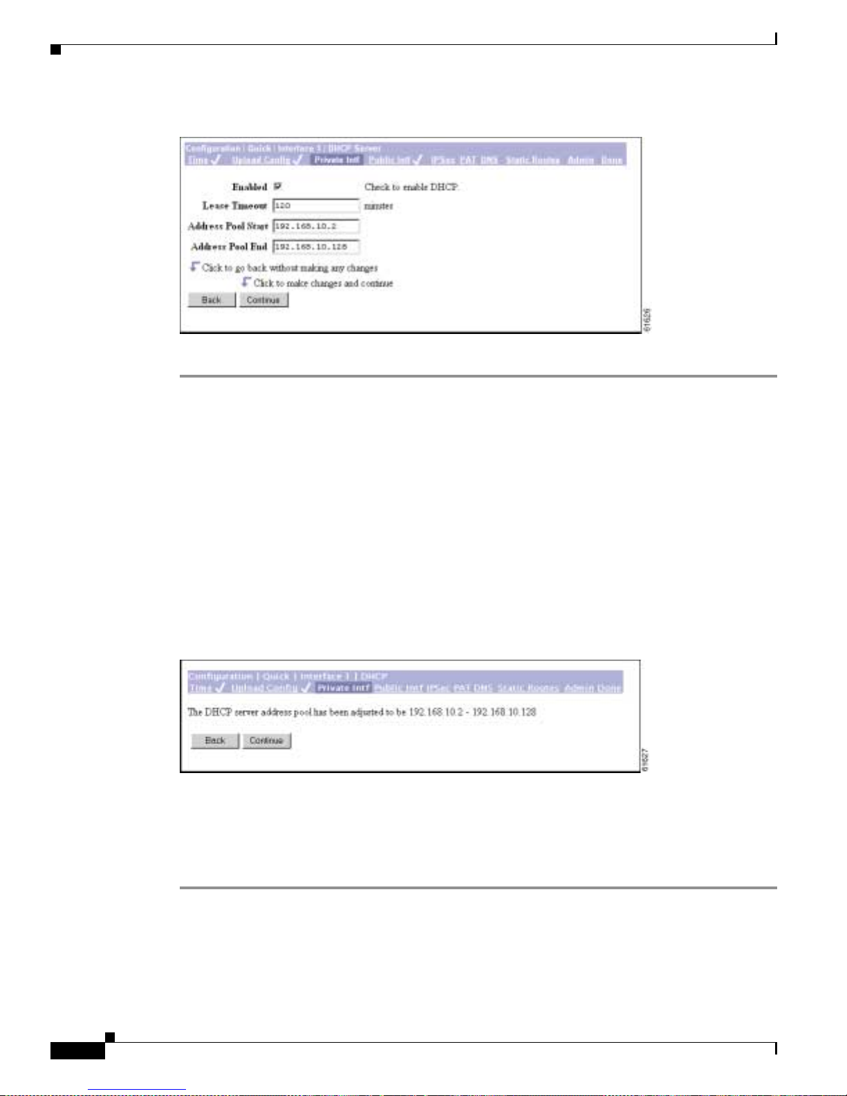
3-8
VPN 3002 Hardware Client Getting Started
OL-2854-01
Chapter 3 Using the VPN 3002 Hardware Client Manager for Quick Configuration
Configurin g the Private Interface
Figure 3 -8 Configuration | Quick | Private Interface | DHCP Server Screen
Step 1 Check the Enabled box to enable DHCP services for this interface.
Step 2 In the Lease Timeout field, enter the amount of time, in minutes, that DHCP clients own the IP address
the DHCP server assigns. The m inimu m i s 5, m ax imum is 500, 000 a nd defau lt is 12 0 minut es.
The Lease Timeout period you configure applies only when the tunnel to the VPN Concentrator is
established. Wh en t he tu nnel is not est abl ishe d, the Lea se Timeout peri od is 5 m inut es .
Step 3 In the Address Pool Start/End fields enter the range of IP addresses that this DHCP server can assign,
using dotted deci mal not at ion (fo r example, 10 .1 0.9 9.51 - 1 0. 10.99. 178 ). Be su re no ot her d evice is
using these addre sses on t he ne twork . The de fault a ddress pool i s 1 27 I P ad dresse s, and t he sta rt o f the
range is next IP address afte r that of the private interface. You can configure another range of IP
addresses for the pool, but in no case can the po ol have more than 127 addresses.
Step 4 Click Continue to save your changes.The Manager displays the Con figuration | Quic k |
Private Interface | DHC P se r ver a ddr es s po ol s cre e n.
Figure 3-9 Configuration | Quick | Private Interface | DHCP Server Address Pool Screen
This screen confirms the DHC P server addre ss pool rang e you ente red.
Step 5 Click Continue to apply your choice and proce ed. Click Back to return to the Configuration | Quick |
Private Interface | DH CP S erver sc reen .
Step 6 You mi ght ne ed t o rest art the M ana ger and q uick configu ra tion f ro m th e logi n scre en .
Page 47
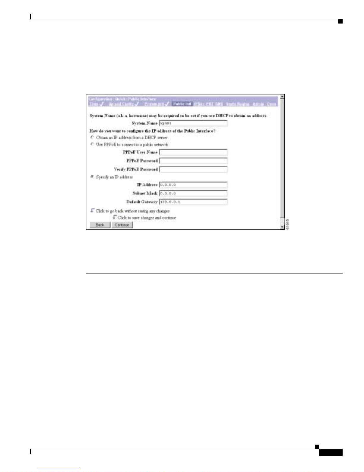
3-9
VPN 3002 Hardware Client Getting Started
OL-2854-01
Chapter 3 Us ing the VPN 3002 Hardware Client Manager for Quick Configuration
Configuring the Public Interface
Configuring the Public Interfac e
The Manager displays the Configuration | Qui ck | Public Inter face scre en.
Figure 3-10 Configuration | Quick | Public Interface Screen
The public interface can obtain an IP address in one of three ways: using DHCP, PPPoE, or by static
addressing. You configure one of these methods; de pe nding on the m e thod you choo se , com ple te
Step 2, or Steps 3 and 4, or Steps 5–8.
Step 1 Assign a System Name , also k nown a s a h ostna me. Th is is o pti onal unl ess yo u u se DH CP to obta in an
IP address and your ISP requires a hostname .
Step 2 To have the DHCP server assign the public interface IP address, subnet mask, and default gateway,
accept the default value, Obtain an IP address from a DHCP server.
Step 3 To have Point-to-Point Protocol ov er E thernet (PPPoE) establish the connection between the VPN 3002
and the central-site VPN C oncentra tor, select Use PPPoE to connect to a public network.
Step 4 For a PPPoE connection, enter the PPPoE username and password. V erify the password by reentering it.
The maximum number of c haracte rs for eith er user name or password is 64.
Step 5 To assign a static IP address, subne t mask, and de fault gateway, select Specify an IP address.
Step 6 To specify an IP address, in the IP Address field, enter the IP address for this interface, using dotted
decimal notatio n (fo r exa mple , 19 2.1 68. 12.34 ). Be su re n o o the r device i s using thi s add re ss o n th e
network.
Step 7 If you specify an IP address, in the Subnet Mask field, enter the subnet mask for this interface, using
dotted decimal n ot ation ( for exampl e, 255 .255. 255 .0) . Th e Ma nage r aut omat ical ly s uppl ie s a s ta nd ard
subnet mask appropriate for the IP address you just entered. For example, an IP address of 192.168.12.34
is a Class C address, and the standard subnet mask is 255.255.255.0. Y ou can accept this entry or change
it.
Page 48

3-10
VPN 3002 Hardware Client Getting Started
OL-2854-01
Chapter 3 Using the VPN 3002 Hardware Client Manager for Quick Configuration
Configuring the Public Interface
Step 8 If you specify an IP address, in the Default Gateway field, enter the IP address or hostname of the system
to which the VPN 3002 should forward packets that do not have a static route. The default gateway must
be accessible from the VP N 3 002 pu blic net work. If you a re usi ng D HC P to ac qui re t he p ubli c IP
address, DHCP usual ly su ppli es the d efault gateway, and you should leave this field b lank.
T o specify no default gateway—which means the VPN 3002 drops unrouted packets—leave this field at
0.0.0.0.
Step 9 Click Continue to apply your choices to the int erface and p roceed . Click Back to return to the
Configuration | Quick | Private Interface
screen.
See the sections that follow for more information about DHCP, PPPoE, and static addressing.
DHCP
Dynamic Host Configuratio n Prot ocol (D HCP) is a c ommun ica tions pro toc ol tha t le ts IP ho sts i n its
network automatically obtain IP addresses from a limited pool of addresses for a fixed length of time, or
lease period. Using DHCP simplifies configuration since you can manage the assignment of IP addresses
from a central point. You do not need to manually enter an IP address for the public interface, and you
do not need to know what IP addresses are co nsidered valid on a par ticular ne twork.
The DHCP server for the Publi c interfac e resides on th e public network.
PPPoE
PPP over Ethernet (PPPoE) is a proposal that specifies how a network client interacts with a service
provider’s equipment, such as a broadband modem—xDSL, cable, or wireless—to achieve access to
high-speed data networks. It relies on the Ethernet and PPP standards. It includes an authentication
strategy that requires a username and password to create a PPPoE session on the VPN 3002.
If a PPPoE session fails due to a PPP authentication failure, the VPN 3002 does not attempt a new session
until 30 seconds have passed.
Specify an IP address
This option enabl es y ou to se t a stat ic IP addre ss, subne t m ask , an d d efaul t gateway for the pu bli c
interface.
Page 49

3-11
VPN 3002 Hardware Client Getting Started
OL-2854-01
Chapter 3 Us ing the VPN 3002 Hardware Client Manager for Quick Configuration
Configuring IPSec
Configuring IPSec
After you click Continue to apply your changes to the Publi c Interface parameters, the Manager displays
the Configuration | Quick | IPSec screen.
Figure 3-11 Configuration | Quick | IPSec Screen
This screen lets you conf igu re the IPS ec para meter s. IPSe c is the pro toco l that enable s the VPN 300 2 to
connect to the VPN Concentrator over a secure VPN tunnel. The VPN 3002 can also establish IPSec
tunnels to other I PSec se curit y gat eways, inclu ding the Cisco PIX firewall, and Cisco I O S rout ers.
Step 1 In the Remote Server field, enter the IP address or hostname of the VPN Concentrator to which this
VPN 3002 hardware client conn ects . Note tha t to enter a hostn ame, a DN S server must be configure d.
Step 2 Check the IPSec over TCP box if you want to c onne ct us ing IPSe c over TCP. This feature must also be
enabled on the VP N C onc en tra tor to w h ich thi s V PN 3 002 c onn ec ts.
Step 3 Enter the IPSec over TCP port number. You can enter only one port. The port that you configure on this
VPN 3002 must also be configured on the VPN Concen trato r to which thi s VPN 3002 conn ects.
Note If you enter a well-known port, for example port 80 (HTTP) or port 443 (HTTPS), the system
displays a warning to notify you that the protocol associated with that port will no longer
work on the pub lic in terfa ce, w ith the c on seq uenc e tha t you c a n n o lo nge r use a b rowser t o
manage the VPN 3002 throu gh the publi c interface. To solve this problem, reconfigure the
HTTP/HTTPS management to different ports.
Step 4 Check the Use Certificate box to use digital certificates for authentication. If you are using digital
certificates, there is no need to enter a group name and group password.
Step 5 Select a Certificate Transmission option. If you want the VPN 3002 to send the peer the identity
certificate and all issu ing certific ates (including the roo t certifica te and any subo rdinate CA certif icates),
click Entire certificate chain. If you want to send the peer only the identity certificate, click Identity
certificate only.
Page 50

3-12
VPN 3002 Hardware Client Getting Started
OL-2854-01
Chapter 3 Using the VPN 3002 Hardware Client Manager for Quick Configuration
Configuring IPSec
Step 6 If you are not using digita l certificate s, in the Gr oup Name field, enter a unique nam e for this gr oup
(maximum is 32 characters, case-sensitive). This is the same group name that you configure for this VPN
3002 on the central-site VPN Conc entrat or.
Step 7 If you are not using digital c ertificates , in the Group Password field, enter a un ique password for this
group (minimum is 4 characters, max imum is 32, case-sensi tive). This is the same gro up password that
you configure for this VPN 3002 on the central-site VPN Concentrator. The field displays only asterisks.
Step 8 In the Group Verify field, reenter the group password to verify it. The field displays only asterisks.
Step 9 If you are not using d ig ital cert ificat es, i n the Use r Na me field, en ter a un ique na me for th e use r in t his
group (maximum is 32 characters, case-sensitive). This is the same username that you configure for this
VPN 3002 on the central-site VPN Conc entra tor.
Step 10 In the User Password field, ente r the passwo rd for this use r (maximum is 32 char acters). Thi s is the same
user password that you configure for th e VPN 3002 on the centr al-site VPN Conce ntrator.
Step 11 In t he U se r Verify field, reenter the user passwo rd to verif y i t. The field displ ays only a ster isks.
Note When you enable interactive hardware client authentication for a group, the VPN Concentrator
pushes that policy to th e V PN 3002 s in t he g rou p. If yo u set a use rnam e an d p ass word on t he V PN
3002 and later enable interac tiv e hardware clie nt authenticatio n for the group to which t he VPN 3002
belongs, the software delet es the user name and password from th e configuration file, and from the
password field in the html interface. When you t ry to conne ct, the softwa re prompt s you for a
username and password .
Step 12 Click Continue to a pply yo ur ch ange s a nd pr oc eed. Cli ck Bac k if yo u want to r etur n to the
Configuration | Quick | Public Interface scr een.
Page 51

3-13
VPN 3002 Hardware Client Getting Started
OL-2854-01
Chapter 3 Us ing the VPN 3002 Hardware Client Manager for Quick Configuration
Configuring PAT or Network Extension Mode
Configuring PAT or Network Extension Mode
The Manager displays the Configuration | Q uick | PAT screen.
Figure 3-12 Configuration | Quick | PAT Screen
You use this scr een to con figure this VP N 3002 to use ei ther PAT or Network Extens ion mode.
Step 1 Accept the default, Yes, if you want to use PAT. Otherwise, check No, use Network Extension mode.
Note that you ca nno t di sable PAT if you have not c hang ed the IP add re ss for t he pr ivate interface .
Step 2 Click Continue to proceed with quick configuration, or click Back to return to the Configuration | Quick
| IPSec screen.
See the sections be low for more inf orm a tion a bo ut PAT and Networ k Ex te nsion m ode.
Online Technical Snapshot Explains PAT and Network Extension Modes
To view a brief interactive multimedia piece that explains the differences between the two modes, go to
this url:
http://www.cisco.com/mm/techsnap/VPN3002_techsnap.html
Your web browser must be equipped with a current version of the Mac romedia Flash Player to view the
content. If you are unsure whether your browser has the most recent version, you may want to download
and install a f ree copy f rom :
http://www.macromedia.com/shockwave/download/index.cgi?P1_Prod_Version=ShockwaveFlash
Client Mode (PAT)
Client mode, also called Port Address Translation (PAT) mode, isolates all devices on th e VPN 3002
private network from those on th e c orpor ate n etwork. I n PAT mode:
• IPSec encapsulates al l traffic going from the private network of the VP N 3002 to the ne twork(s)
behind the Internet Key Exchange (IKE) peer, that is, the central-site VPN Concentrator.
Page 52

3-14
VPN 3002 Hardware Client Getting Started
OL-2854-01
Chapter 3 Using the VPN 3002 Hardware Client Manager for Quick Configuration
Configuring PAT or Network Extension Mode
• PAT mode employs NAT (Network Address Translation). NAT translates the network addresses of
the devices connected to the VPN 3002 private interface to the IP addre ss of the VPN 3 002 public
interface. The central-site VPN Concentrator assigns this address. NAT also keeps track of these
mappings so that it can forwar d repli es to the co rrect device.
All traffic from the private network appears on the network behind the central-si te VPN Con centrator
(the IKE peer) with a single source IP address. This IP address is the one the central-site VPN
Concentrator assigns to the VPN 300 2. The IP addresse s of the comput ers on the VPN 3002 private
network are hidden. You cannot ping or access a d evice on the VPN 3002 private network from outside
of that private network, or directly fro m a device on the private network at th e centr al site.
Client Mode with Split Tunneling
You assign the VPN 3002 to a cl ient group on the central- site VPN Con centrat or. If you enable split
tunneling for that gro up, IPSec and PAT are applied to all traffic that travels through the VPN 3002 to
networks within the network list for that group behind the central-site VPN Concentrator.
Traffic from the VPN 3002 to any destination other than those within the network list for that group on
the central-site VPN Concentrator travels in the clear without applying IPSec. NAT translates the
network addresses of the devices connected to the VPN 3002 private interface to the assigned IP address
of the public interface and also keeps track of the se mappings so that it can forw ard replies to the c orrect
device.
The network and addresses on the private side of the VPN 3002 ar e hidd en, an d cannot be ac cessed
directly.
VPN Concentrator Settings Required for PAT
For the VPN 3002 to us e PAT, you must meet these requirements for the central-site VPN Concentrator.
1. The VPN Concentrator at the central site must be running Software version 3.x or later.
2. Address assignment must be enable d, by whatever method you choose to assign ad dresses (the
options are DHCP, address pools, per user, or client-specified). If the central-site VPN Concentrator
uses address pools for a ddre ss assi gnme nt, make su re t o c onfigure the addr es s pool s y our n etwork
requires. Refer to the chapter, “Address Management,” in the VPN 3000 Series Concentrato r
Reference Volume 1: Configuration.
3. Configure a group to w hic h you a ssign thi s VP N 3 002 . Thi s inc lude s assi gnin g a gro up name and
password. Refer to the chapte r, “User Management,” in the VPN 3000 Series Concentrator
Reference Volume 1: Configuration.
4. Configure one or more users for the gro up, inc luding u ser name s and passwor ds.
Network Extension Mode
Network Extension mode all ows the VPN 3002 to prese nt a single , routab le netwo rk to the remot e
private network over the VPN tunnel. IPSec encapsulates all traffic from the VPN 3002 private network
to networks behind the central -site VPN Con centrat or. PAT does not apply. Therefore, devices behind
the VPN Concentr ato r h ave direct a cce ss to devices on the VP N 3 002 private network over the tu nnel ,
and only over the tunnel, and vice versa. The VPN 3002 must initiate the tunnel, but after the tunnel is
up, either side can initiate data exchange.
Page 53

3-15
VPN 3002 Hardware Client Getting Started
OL-2854-01
Chapter 3 Us ing the VPN 3002 Hardware Client Manager for Quick Configuration
Configuring PAT or Network Extension Mode
In this mode, the central-site VPN Concentrator does not assign an IP address for tunneled traffic (as it
does in Client/PAT mode). The tunnel is terminated with the VPN 3002 private IP address (the assigned
IP address). To use Network Extension mode, you must configure an IP address other than the default of
192.168.10.1 an d d isable PAT.
In Network Extension mode, the VPN 3002 automatically attempts to establish a tunnel to the VPN
Concentrator. However, if you enable interactive unit authentication in either Client or Network
Extension mode, t he t unne l e stab lish es w hen y ou pe rform the following st ep s.
Step 1 Click the Connection/Login Status button on the VPN 3002 Hardware Client log in scree n. The
Connection/Login screen displays.
Step 2 Click Connect Now in the Connection/Login screen.
Step 3 Enter the user name and pa ssword for the VPN 3002.
Alternatively, you can initiate a tunnel by clicking Connect Now on the in the Monitoring | System
Status screen .
Network Extension Mode per Group
VPN Concentrator software versions 3.6 and later let a network administrator restrict the use of network
extension mode. On the VPN Concentrator, you enable network extension mode for VPN 3002 hardware
clients on a group basis.
Note If you disallow network extension mode , wh ic h is the defau lt se tting on th e VPN Co nce ntr ator, the
VPN 3002 can conn ec t t o that VP N C onc e ntra tor in PAT mode onl y. In this case, be c are ful th at a ll
VPN 3002s in the group are configur ed for PAT mode. If a VPN 3002 is configur ed to use network
extension mode and the VPN Con cent rat or to whic h it conn ec ts di sall ows network exten sion mo de ,
the VPN 3002 will attempt to connect every 4 seconds, and every attempt will be rejected; this is the
equivalent of denial of serv ice at tack.
Network Extension Mode with Split Tunneling
You always assi gn t he V PN 3002 t o a c lien t gr oup on the cen tra l-site VPN Conc e ntrat or. If you enable
split tunneling for that group, IPSec opera tes on all traf fic that tra vels thro ugh the VPN 3002 to networ ks
within the network list for that group be hind the cen tral-site VPN Concentra tor. PAT does not apply.
Traf f ic fro m the VPN 3002 to an y other destinatio n than those wit hin the netw ork list on the centr al-site
VPN Concentrator travels in the clear without applying IPSec. NAT translates the network addresses of
the devices on the VPN 3002 private network to the address of the VPN 3002 public interface. Thus the
network and addresses on the pr ivate side of the VPN 3002 are a ccessibl e over the tunnel, but are
protected from the Internet, that is, they cannot be accessed directly.
VPN Concentrator Settings Required for Network Extension Mode
For the VPN 3002 to use Network Extens ion mode, you must meet these requirements for the cen tral-site
VPN Concentrator.
1. The VPN Concentrator at the central site must be running Software version 3.x or later.
Page 54

3-16
VPN 3002 Hardware Client Getting Started
OL-2854-01
Chapter 3 Using the VPN 3002 Hardware Client Manager for Quick Configuration
Configuring PAT or Network Extension Mode
2. Configure a group to w hich you a ssign this VPN 3 002. Thi s inclu des assigni n g a gro up name and
password. Refer to the chapte r, “User Management,” in the VPN 3000 Series Concentrator
Reference Volume 1: Configuration.
3. Configure one or more users for the gro up, inc luding u ser name s and passwor ds.
4. Configure either a default gateway or a static route to t he VPN 3002 pr ivate network. Refer to th e
chapter, “IP Routin g,” in the VPN 3000 Se ries Con centrator R eference Volume 1: Configuration.
5. If you want the VPN 3002 to be able to reac h devices on other netwo rks that conn ect to the VPN
Concentrator, review your Network Lists. Refer to the chapter, “Policy Management,” in the VPN
3000 Series Concentrator Reference Volume 1: Configuration.
Tunnel Initiation
The VPN 3002 always initiates the tunnel to the central-site VPN Concentrator. The central-site VPN
Concentrator cannot in itiat e a tunnel t o a VPN 3002. Th e VPN 300 2 creat es only one IPSe c tunnel to
the central-site VPN Concentrator, in either PAT or Network Extension mode. The tunnel can support
multiple encrypted data streams between users behind the VPN 3002 and the central site. With split
tunneling enabled, it ca n also suppor t multip le unenc rypted data strea ms to the inter net.
In PAT mode, the tunnel establishes when da ta passes to th e VPN Conc entrat or, or when you click
Connect Now in the Monitoring | System Status screen.
In Network Extension mode, the VPN 3002 automatically attempts to establish a tunnel to the VPN
Concentrator.
Tunnel Initiation with Interactive Unit Authentication
In either Client or Networ k Extens ion mode , when you enable inte racti v e unit authen ticati on, the tunnel
establishes when you perform the following steps.
Step 1 In the VPN 3002 H ardwa re C lie nt logi n scree n, cl ick the Connection/Login Status butt o n . T h e
Connection/Login screen displays.
Step 2 Click Connect Now.
Step 3 Enter the user name and pa ssword for the VPN 3002.
Refer to the sec tio n, “Logging in With Interact ive Unit a nd In dividual U se r Au the nt icat ion, ” in
Chapter 1 of the VPN 3002 Hardware Client Reference for detailed instructions.
Alternatively, you can click Connect Now on the in the Monitoring | System Status screen, after which
the system prompts you to ente r the usernam e and pass word for the V PN 3002. Refe r to the sect ion,
Monitoring | System Status in the “Monitoring” chapter of the VPN 3002 Hardware Client Reference for
detailed instructions.
Data Initiation
After the tunnel i s e stabli shed be twee n the VP N 3 002 an d the ce ntra l-sit e V PN Con ce ntrat or, the VPN
Concentrator can initiate data exchange only in Network Extension mode with all traffic travelling
through the tunnel. If you want the tunnel to remain up indefinitely, you should configure the VPN 3002
for Network Extensi on mode and not use sp lit tunne ling.
Page 55

3-17
VPN 3002 Hardware Client Getting Started
OL-2854-01
Chapter 3 Us ing the VPN 3002 Hardware Client Manager for Quick Configuration
Configuring DNS
Table 3-1 summarizes instances in which the VPN 3002 and the central-site VPN Concentrator can
initiate data exchange.
Table 3-1 Data Initiation: VPN 3002 and Central-Site VPN Concentrator
Configuring DNS
The Manager displays the Configuration | Q uick | DNS scre en.
Figure 3-13 Configuration | Quick | DNS Screen
This screen lets you specify a Domain Name System (DNS) server for your local ISP, which lets you
enter Intern et host names ( for e xample,
mail01) rather than IP addresses for servers as you configure and
manage the VPN 3002. While host names are ea sier to reme mber, using IP addresses avoids problems
that might occur with the DNS server offline or congested. If you use a hostname to identify the
central-site VPN Concentrator, you must configure a DNS server on the VPN 3002 (see Configuration |
System | Servers | DNS).
Step 1 In the DNS Server field, enter the IP address of your local DNS server, u sing dotted decimal notation
(for example, 10.10. 0.11).
Step 2 In the Domain field, enter the local ISP domain name.
Step 3 Click Continue to proceed.
Mode Tunneling Policy
VPN 3002 Can Send
Data First
Central-Site VPN Concentrator Can Send Data
First (after VPN 3002 initiates the tunnel)
PAT All traffic tunneled Yes No
PAT Sp lit tunneli ng
enabled
Yes No
Network
Extension
All traffic tunneled Yes Yes
Network
Extension
Split tunneling
enabled
Yes No
Page 56

3-18
VPN 3002 Hardware Client Getting Started
OL-2854-01
Chapter 3 Using the VPN 3002 Hardware Client Manager for Quick Configuration
Configuring Static Routes
Configuring Static Routes
The Manager displays the Configuration | Qui ck | Static Rout es screen . The Stati c Routes list shows
manual IP routes that have been configured. The format is [destination network address/subnet mask ->
outbound destination] .
Figure 3 -14 Configuration | Quick | Static Routes Screen
You use this screen to add or delete static routes for IP routing.
Step 1 Click Add to add a route to the routing table . The Mana ger displ ays the Co nfiguration | Qui ck | Static
Routes | Add screen.
Step 2 To delete a route, select it, and click Delete. The Manager deletes the route instantly, and there is no
confirmation.
Step 3 Click Continue to proceed.
Page 57

3-19
VPN 3002 Hardware Client Getting Started
OL-2854-01
Chapter 3 Us ing the VPN 3002 Hardware Client Manager for Quick Configuration
Configuring Static Routes
Adding a Static Route
This screen lets you add a new static route to the IP routing table.
Figure 3-15 Configuration | Quick | Static Routes | Add Screen
Step 1 In the Network Address fie ld, enter the network IP address f or this static route . Pack ets with thi s address
will be sent to t he D est inati on below. Use dotted decima l no tati on; for exa mple , 192.1 68. 12.0.
Step 2 In the Subnet Mask field, enter th e subnet mask for the network IP address, using dotted decimal notation
(such as 255.255.255.0). The subnet mask indicates which part of the IP address represents the network
and which part represe nts hosts. T he router subsystem look s at only th e network part.
The Manager automatically supplies a standard subnet mask appropriate for the IP address you just
entered. For example, the IP address 192.168.12.0 is a Class C address, and the standard subnet mask is
255.255.255.0. You can accept this entry or c ha nge i t.
Step 3 In the Metric field, enter the cost for this route. Use a number from 1 to 16, where 1 is the lowest cost.
The routing subsystem always tries to use the least costly route. For example, if a route uses a low speed
line, you might assign a high metric so the system will use it only if all high-speed routes are unavailable.
Step 4 In the Destination Router Address or Interface fields, click a radio button to select the outbound
destination for these packets. You can select only one destination: either a specific router or gateway, or
a VPN 3002 interface.
For Router Addr ess, enter the IP a ddress of the sp ecific route r or gate way to which to route these pa ckets;
that is, the IP address of the next hop between the VPN 3002 and the packet’s ultimate destination. Use
dotted decimal notation; for example, 10.10.0.2.
For Interface, click the dr op-down menu button and sel ect a co nfigured VPN 3002 inter face as the
outbound destination.
Step 5 T o add a ne w static route to the list of conf igured routes, click Add. The new route displays at the bottom
of the Static Routes list.
To discard your entry, click Cancel. The Manager returns to the Configuration | Quick | Static Routes
screen, and the Static Routes list is unchanged.
Page 58

3-20
VPN 3002 Hardware Client Getting Started
OL-2854-01
Chapter 3 Using the VPN 3002 Hardware Client Manager for Quick Configuration
Changing admin Password
Changing admin Password
The Manager displays the Configuration | Q uick | Admin Password screen .
Figure 3-16 Configuration | Quick | Admin Password | Screen
This screen lets you change the password for the admin administrator user. For ease of use during startup,
the default admin password suppli ed with the V PN 3002 is al so admin. Sinc e the admin user has full
access to all manageme nt and administ ration fu nction s on the device, we strongly recommend you
change this password to improve device security. You can further configure all administrator users on the
regular Administration | Access Righ ts | Admin istrators Manager scr een.
Step 1 In the Password field, en ter a new passwo rd. For max imum se curi ty, the password should be at lea st 8
characters long, a mixture of upper- and lower-case alphabetic and numeric characters, and not easily
guessed; for example,
W8j9Haq3. (The field shows only asterisks.)
Step 2 In the Verify field, reente r the new password to verif y it .
Step 3 Click Continue to proceed.
Page 59

3-21
VPN 3002 Hardware Client Getting Started
OL-2854-01
Chapter 3 Us ing the VPN 3002 Hardware Client Manager for Quick Configuration
Finishing Quick Configuration
Finishing Quick Configuration
The Manager displays the Configuration | Qui ck | Done scr een.
Figure 3 -17 Configuration | Quick | Done Screen
You have finished quick configuration, and your entries constitute the active or running configuration.
This configuration has now been sa ved as th e boo t c onfiguration. T he V PN 3 002 now has e nough
information, and it is ope rati onal. The VP N 3002 ca n now establish a secur e VPN tunn el to the
central-site VPN Concentrator.
What Next?
Now that the VPN 3002 is ope rat iona l, you can :
• Explore the Manag er window and other VPN 3002 func tions; see the “U sing Other VPN 300 2
Hardware Client Mana ger Fu nc tio ns” section.
• Proceed to a more detailed and complete system configuration. Refer to the VPN 3002 Hardware
Client Reference for assistance (online only).
Page 60

3-22
VPN 3002 Hardware Client Getting Started
OL-2854-01
Chapter 3 Using the VPN 3002 Hardware Client Manager for Quick Configuration
What Next?
Using Other VPN 3002 Hardware Client Manager Functions
T o use other VPN 3002 Hardware Client Manager functions, click the section you want in the left frame
of the Manager w ind ow or o n th e Ma na ger tool b ar i n the top fr am e of t he M a nage r wind ow.
• Configuration—Configures all the features of the VPN 3002.
• Administration—Controls administrative functions of this device.
• Monitoring—Displays status, statistics, and event logs on this device.
• Save, Save Needed—Saves the active configuration and makes it the boot co nfigurat ion.
• Main—Returns to the main Manager screen.
• Help—Opens another browser window and lets you view online help for the current Manager
screen.
• Support—Opens a Mana ger sc reen w it h link s t o Cisc o suppo rt and do cu ment atio n r es ource s.
• Logout—Logs out of this Ma nager sessio n and retu rns to the logi n screen.
For details on the frames, functions, and icons in the Manager window, see the next section,
“Understan ding t he V PN 3002 H ardwa re C lie nt Ma nage r Window.”
For details on the VPN 3002 hardware, all the functions available in the VPN 3002 Hardware Client
Manager, or using the command-line interface, refer to the VPN 3002 Hardware Client Reference (online
only).
Page 61
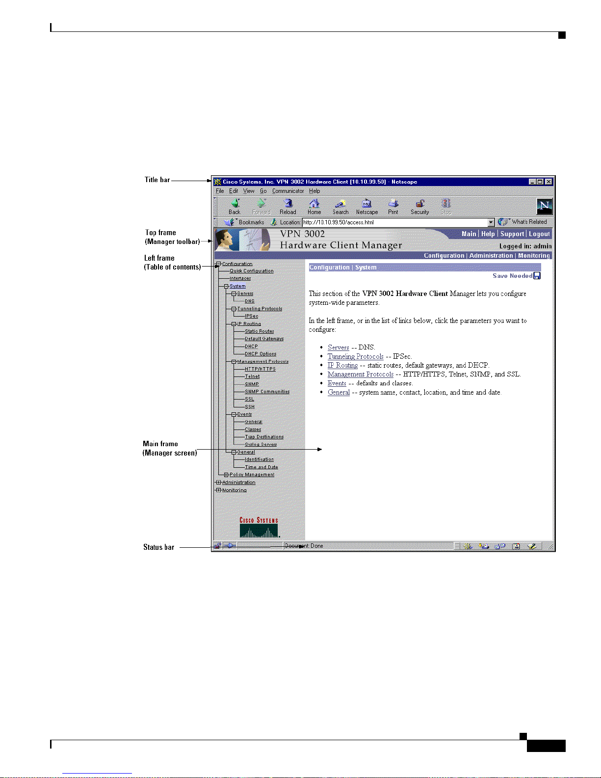
3-23
VPN 3002 Hardware Client Getting Started
OL-2854-01
Chapter 3 Us ing the VPN 3002 Hardware Client Manager for Quick Configuration
Understanding the VPN 3002 Hardware Client Manager Window
Understanding the VPN 3002 Hardware Cl ient Manager Window
The VPN 3002 Hardware Clien t Manag er window on your browser con sists of thr ee frames —top, left,
and main—and it provides helpful messages and tips as you move the mouse poin ter ov er windo w items.
The title bar and status bar a lso provide useful informa tion.
Figure 3 -18 VPN 3002 Hardware Client Manager Window
Title bar
Top frame
(Manager toolbar)
Left frame
(Table of contents)
Main frame
(Manager screen)
Status bar
Title bar The title bar at the top of the bro wse r wind ow includes the VPN 3002
device name or IP a dd ress i n br ac kets, fo r exa mple , [1 0. 10. 4.6].
Status bar The status bar at the bottom of the browser window displays Manager
activity and explanatory me ssage s for som e i tem s.
Page 62

3-24
VPN 3002 Hardware Client Getting Started
OL-2854-01
Chapter 3 Using the VPN 3002 Hardware Client Manager for Quick Configuration
Understanding the VPN 3002 Hardware Client Manager Window
Mouse pointer and tips As you move the mouse pointer over an active area, the pointer
changes shape and icon s change col or. A description also appea rs in
the status bar area. If you momentarily rest the pointer on an icon, a
descriptive tip appears for that icon.
Top frame
(Manager toolbar)
The Manager tool b ar i n t he top fram e pr ovides q uic k a cce ss to
Manager features. These include the following icons:
Click the Main tab to go to the main Manager screen, and to close all
subordinate sections and titles in the left frame.
Click the Help tab to open context-sensitive online help. Help opens
in a separate browser window that yo can move or resize as you want.
Close the help wi ndow when you are finished.
Click the Support tab to open a Manager screen with links to Cisco
support and documentation re sources.
Click the Logout tab to log out of the Manager and return to the login
screen.
Logged in: [userna me] The administrator username you used to log in to this Manager session.
Click the Configuration tab to go to the main Conf iguration scree n, to
open the first level of subordinate Configuration pages in the left
frame if they are not alread y open, a nd to close any open
Administration or Monitoring pages in the left frame.
Click the Administration tab to go to the main Ad ministrat ion scr ee n,
to open the first level of subordinate Administration pages in the left
frame if they are not alread y open, a nd to close any open
Configuration or Monitoring pages in the left frame.
Click the Monitoring tab to go to the main Mo nitoring screen, to open
the first level of subordinate Monitoring pages in the left frame if they
are not already open, an d to close any open Con figuration or
Administration pages in the left frame.
Save Click the Save icon to save the active configuration and make it the
boot configuratio n . I n t his state, the reminder indica tes th at t he act ive
configuration is th e sam e a s t he boot co nfigur ati on , but you c an save
it anyway. When you change the configuration, the reminder changes
to Save Needed.
Page 63

3-25
VPN 3002 Hardware Client Getting Started
OL-2854-01
Chapter 3 Us ing the VPN 3002 Hardware Client Manager for Quick Configuration
Understanding the VPN 3002 Hardware Client Manager Window
Save Needed This reminder indicates that yo have changed the active configuration.
Click the Save Nee ded icon to save the acti ve configuration and mak e
it the boot configuration. As you make configuration entries, they take
effect immediately a nd ar e inc l uded in t he ac t ive, or runn ing,
configuration. However, if you reboot the VPN 3 002 wit hou t saving
the active configuration, and configuration ch an ges are lo st. Clic king
on this reminder saves the active configuration as the boot
configuration and restor es the Save reminder.
Refresh Click the Refresh icon to refresh (update ) the scre en conte nts on
screens where it appears (mostly in the Monito ri ng secti on) . Th e d ate
and time above this reminder indicate when the screen was last
updated.
Reset Click the Reset icon to reset, or start anew, the screen contents on
screens where it appears (mostly in the Monitoring section).
Restore Click the Restore icon to restore the screen contents to their status
prior to when you last clicked the Reset icon.
Click the Cisco Syste ms logo to open a br owser and go t o t he
Cisco.com web site, www.cisco.com
Left frame
(Table of Contents)
On Manager screens, the left frame provides a table of contents. The
table of contents uses t he familia r Windows Explorer metaphor of
collapsed and expanded entries.
Main section titles
(Configuration,
Administration,
Monitoring
Click a title to open subordinate sections and titles, and to go to that
Manager screen in the main frame.
Closed or collapsed Click the closed/collapsed ic on to open subordinate sections and titles.
Clicking on this icon does not change the screen in the main frame.
Open or expanded Click the open/expanded icon to close subordinate sec tio ns and t itles.
Clicking on this icon does not change the screen in the main frame.
Main frame
(Manager screen)
The main frame displays the current VPN 3002 Hardware Client
Manager screen.
Many screens include a bullet list of links and descriptions of
subordinate sections and titles. you can click a link to go to that
Manager screen, and open subordinate sections and titles in the table
of contents.
Page 64

3-26
VPN 3002 Hardware Client Getting Started
OL-2854-01
Chapter 3 Using the VPN 3002 Hardware Client Manager for Quick Configuration
Understanding the VPN 3002 Hardware Client Manager Window
Page 65

CHAPTER
4-1
VPN 3002 Hardware Client Getting Started
OL-2854-01
4
Using the Command-Line Interface for Quick
Configuration
This chapter tel ls yo u h ow to comp lete qu ick configurat ion of the syst em u si ng t he V PN 3002
command-line i n terfa ce ( CL I).
Quick configuration supplies the minimal parameters needed to make the VPN3002 operational.
The CLI is a menu-based configuration, administration, and monitoring system built into the VPN 3002.
You ca n use it from the co nsole o r i n a Telnet or SSH session.
As you proceed, refer t o the data you record ed in Table 2-2 on page 2-6.
About Quick Configuration
You can go thro ugh quick c onfiguration multip le times, and althoug h it is easiest to c onfigure its
parameters in seque nce , you c an se t a nd revisit para m eters in w hat ever order you c hoo se.
Entries are case-sensitive; for example,
admin and ADMIN are different passwor ds.
The system displays more tip s and example s than ap pear in the dialog here .
The system shows current or default entries in brackets; for example,
[ 10.10.4.6 ].
After each entry, press the Enter key on the console keyboard.
Configuration entries take effect as soon as you enter them, and they constitute the active, or running,
configuration. The system automatically saves your entries when you press the Enter key.
If you make a mista ke, th e syste m displ ays a n erro r m es sag e and r ep eats t he p revious pr omp t. You can
often enter a correct value and proceed, but in some cases you may need to restart the section to correct
an earlier error. See Ap pendix A, “Troubleshootin g and Syst em Er rors ” for more deta ils.
Page 66

4-2
VPN 3002 Hardware Client Getting Started
OL-2854-01
Chapter 4 Using the Command-Line Interface for Quick Co nfiguration
Starting Quick Configurati on
Starting Quick Configuration
To use the comma nd- line int erfac e (C LI) f or qu ick c onfigurati on of t he VPN 3002:
Step 1 After booting the VPN 3002, start either the console or a Telnet or SSH session, and connect to the
private interface of the VPN 3002 by entering the IP address for that interface.
The system displays initialization and boot messages such as:
Boot-ROM Initializing...
Boot configured 16 MB of RAM.
...
Loading image ..........
Verifying image checksum ...........
Active image loaded and verified...
Starting loaded image...
Image Loader Initializing...
Decompressing & loading image ............
Verifying image checksum ...........
Active image loaded and verified...
Starting loaded image...
Starting power-up diagnostics...
pSH+ Copyright (c) Integrated Systems, Inc., 1992.
Cisco Systems, Inc./VPN 3002 Hardware Client Version 3.0(REL) Feb 02 2001 09:53:35
Features:
Initializing VPN 3002 Hardware Client ...
Initialization Complete...Waiting for Network...
Login:_
Step 2 At the cursor, enter the login name: admin. At the password prompt, enter the default password: admin.
Login: admin
Password: admin
The system displays the opening message and prom pts you to sele ct an adm inistrative task.
Welcome to
Cisco Systems
VPN 3002 Hardware Client
Command Line Interface
Copyright (C) 1998-2001 Cisco Systems, Inc.
1) Configuration
2) Administration
3) Monitoring
4) Save changes to Config file
5) Help Information
6) Exit
Main -> _
Step 3 At the cursor, enter 1 for Con figurat ion.
Step 4 The system prompts you to select a configuration task.
Page 67

4-3
VPN 3002 Hardware Client Getting Started
OL-2854-01
Chapter 4 Us ing the Command-Line Interface f or Quick Configuration
Setting the Time and Date
1) Quick Configuration
2) Interface Configuration
3) System Management
4) Policy Management
5) Back
Config -> _
At the cursor, enter 1 to start quick co nfiguration .
Setting the Time and Date
To set the time and date on the VPN 3002:
Step 1 The system prom pts y ou to se t t he tim e on yo ur device. Th e tim e in brac kets is t h e cu rre nt d evice t ime .
-- : Set the time on your device. The correct time is very important,
-- : so that logging entries are accurate.
-- : Enter the system time in the following format:
-- : HH:MM:SS. Example 21:30:00 for 9:30 PM
> Time
Quick -> [ 10:34:17 ] _
At the cursor, enter the correct device time in the format HH:MM:SS, using 24-hour notation. For
example, enter 4: 24 p.m. a s 1 6:24: 0 0.
Step 2 The system prompts you to set the date. The num ber in bra ckets is the curre nt device date.
-- : Enter the date in the following format.
-- : MM/DD/YYYY Example 06/12/1999 for June 12th 1999.
> Date
Quick -> [ 01/18/2001 ] _
At the cursor, enter the correct date in the format MM/DD/YYYY. Use four digits to enter the year.
For example, enter June 12, 2001 as 06/12/ 2001.
Step 3 The system prompts you to set the time zone. The time zone selec tions ar e offsets in hours relative to
GMT (Greenwich Mean Time), which is the basis for Internet time synchronization. The number in
brackets is the current time zone offset.
-- : Set the time zone on your device. The correct time zone is very
-- : important so that logging entries are accurate.
-- : Enter the time zone using the hour offset from GMT:
-- : -12 : Kwajalein -11 : Samoa -10 : Hawaii -9 : Alaska
-- : -8 : PST -7 : MST -6 : CST -5 : EST
-- : -4 : Atlantic -3 : Brasilia -2 : Mid-Atlantic -1 : Azores
-- : 0 : GMT +1 : Paris +2 : Cairo +3 : Kuwait
-- : +4 : Abu Dhabi +5 : Karachi +6 : Almaty +7 : Bangkok
-- : +8 : Singapore +9 : Tokyo +10 : Sydney +11 : Solomon Is.
Page 68

4-4
VPN 3002 Hardware Client Getting Started
OL-2854-01
Chapter 4 Using the Command-Line Interface for Quick Co nfiguration
Uploading Configuration
-- : +12 : Marshall Is.
> Time Zone
Quick -> [ -5 ] _
At the cursor, enter the time zone offset in the format +/- NN, or accept the default, -5, for U.S.
Eastern Standard Time.
Step 4 The system prompts with a menu to enable DST (Daylight-Saving Time support. During DST , clocks are
set one hour ahead of standard tim e. Enabli ng DST supp ort means th at the VP N 3002 auto matical ly
adjusts the time zone for DST or standard time. If your system is in a time zone that use s DST, you must
enable DST support .
1) Enable Daylight Savings Time Support
2) Disable Daylight Savings Time Support
Quick -> [ 1 ] _
At the cursor, enter 2 to disable DST supp ort, or accept the de fault, 1, to enable DST supp ort, and
continue to the n ext sect ion.
Uploading Configuration
To use the local console PC terminal emulation package to transfer (upload) configuration files from
your PC, or from a system accessible to your PC, to the VPN 3002 flash memory:
Step 1 The system prompt s you t o choos e wh eth er or n ot t o uplo ad a configu rat ion file.
1) Upload Config File
2) Do Not Upload Config File
3) Back
Quick -> [2]
At the cursor, enter 1 Upload Config File to transfer a configuratio n file. I f you do no t wa nt to use an
already existing con figu ration f ile, acce pt the def ault, 2 , Do Not Upload C onf ig File and continue to the
next section.
Configuring the Private Interfa ce
To configure the VPN 3002 private interface, use these instructions:
For the VPN 3002 to become fully operati onal, yo u must configure th e two inter faces you physica lly
connected to your network in the “Co nne ctin g Ne twork Ca ble s” section on page 2-3.
• The private interface is the interface to your internal LAN (private network).
• The public interface is the interface to the public network.
Page 69

4-5
VPN 3002 Hardware Client Getting Started
OL-2854-01
Chapter 4 Us ing the Command-Line Interface f or Quick Configuration
Configuring the Private Interface
Note If you do not ch ang e the pr ivate interface I P a dd re ss, you c annot disa ble PAT mode. Tha t i s, you
cannot use Network Extension mode unless you configure a private IP address other than the default,
which is 192.168.1 0. 1
Step 1 The system prompts you to configur e the VPN 3002 pr ivate interface.
This table shows current IP addresses.
Intf Status IP Address/Subnet Mask MAC Address
------------------------------------------------------------------------------Pri Intf | UP | 192.168.10.1/255.255.255.0 | 00.90.A4.00.25.A8
Pub Intf | Disabled | 0.0.0.0/0.0.0.0 | 00.90.A4.00.25.A9
------------------------------------------------------------------------------DNS Server(s): DNS Server Not Configured
Default Gateway: 130.0.0.1
WARNING:-- The IP Address for the Private Interface is at the default value
WARNING:-- of 192.168.10.1. Keeping this Private Interface address will prevent
WARNING:-- Network Extension Mode from being enabled.
1) Configure the Private Interface
2) Skip the Private Interface Configuration
3) Back
Quick -> [ 2 ]
At the cursor, enter 1 Configure the Private Interface if you want to change the private interface
IP address or subnet mask. If you do not want to chan ge the private interface ad dress, acce pt the
default, 2, to continue with quic k configurati on. We assume that you enter 1.
Step 2 The system prompts you to enter an IP address.
This table shows current IP addresses.
Intf Status IP Address/Subnet Mask MAC Address
------------------------------------------------------------------------------Pri Intf | UP | 192.168.10.1/255.255.255.0 | 00.90.A4.00.25.A8
Pub Intf | Disabled | 0.0.0.0/0.0.0.0 | 00.90.A4.00.25.A9
------------------------------------------------------------------------------DNS Server(s): DNS Server Not Configured
Default Gateway: 130.0.0.1
> Enter IP Address
Quick Private Interface -> [ 192.168.10.1 ] _
T o re conf igure the IP addres s for the private interface, at the curso r enter the IP address fo r the VPN
3002 pri v at e in ter fa ce, usin g do tte d deci ma l no tat ion ; for e xam ple, 192 .16 8. 12. 34. Be sure no othe r
device is using this address on the network.
Step 3 The system prompts you for t he private interface subne t mask. Th e entry i n brackets is the standar d
subnet mask for the IP address you en tered above. For example, an IP address of 192 .168.12. 34
is a
Class C address, a nd t he st anda rd subne t m ask i s 255 .255.2 55. 0.
> Enter Subnet Mask
Quick Private Interface -> [ 255.255.255.0 ]_
To reconfigure the subnet mask for the private interface, at the cursor enter the new subnet mask, using
dotted decimal notation.
Page 70

4-6
VPN 3002 Hardware Client Getting Started
OL-2854-01
Chapter 4 Using the Command-Line Interface for Quick Co nfiguration
Configurin g the Private Interface
Step 4 The system gives you the option of configu ring the DHCP server. The DHCP server for the private
interface lets IP hosts in its network automatically obtain IP addresses from a limited pool of addresses
for a fixed length of time, or lease period . Befor e the lease period expir es, the VP N 3002 displa ys a
message offering to renew it. If the lease is not renewed, the connection terminates when the lease
expires, and the IP address becomes available for reuse. Using DHCP simplifies configuration since you
do not need to know what IP addresses are co nsidered valid on a par ticular ne twork.
DHCP Server: Enabled
Address Pool: 192.168.10.2 - 192.168.10.128
1) Disable DHCP Server
2) Enable and Configure DHCP Server
3) Enable DHCP server with existing parameter values.
4) Back
Quick -> [ 3 ]
Choose one of the m enu opti ons li sted .
• If you want to disable the DHCP server, at the prompt enter 1 Disable DHCP Server, and continue
with quick configurati on .
• If you want to enable and configure the DHCP server, at the prompt enter 2 Enable and Configure
DHCP Server, and follow Steps 6 through 9 below.
• If you want to enable the DHCP server with existing parameters, at the prompt enter 3.
Step 5 If you choose 2 Enable and Configure DHCP server, the system displays the server parameters.
1) Enable/Disable DHCP
2) Set DHCP Lease Timeout
3) Set DHCP Pool
4) Back
5) Continue
Quick -> [ 3 ]
Enter the number for the par am eter you want t o co nfigure, an d pr ess Enter to continue with quick
configuration.
Step 6 To Enable or disable DHCP, at the prompt, enter 1. The system displays the Enable DHCP parameter.
1) Enable DHCP
2) Disable DHCP
Quick -> [ 1 ]
Choose 1 to enable the DHCP server, or 2 to disable it.
Step 7 The DHCP lease period is the amount of time, in minutes, that the private interface owns the IP address
the DHCP server assigns. T he m ini mu m is 5, max imum is 500, 00 0, and th e de fault i s 120 mi nute s.
To set the lease period, at the prompt, enter
2. The system displays the DHC P Lease Timeout
parameter.
Quick -> [ 2 ]
> Lease Timeout (5-500000) minutes
Quick -> [ 120 ]
Page 71

4-7
VPN 3002 Hardware Client Getting Started
OL-2854-01
Chapter 4 Us ing the Command-Line Interface f or Quick Configuration
Configuring the Public Interface
At the prompt, enter the number of minutes for the DHCP lease period, or press Enter to accept the
default, 120 minute s, an d cont inue wi th q ui ck c on figuratio n.
Step 8 The DHCP pool is the range of IP addresses that this DHCP server can assign. The default address pool
is 127 IP addresses, and the start of the range is the next IP address after that of the private interface.
You can configure an oth er ra nge of IP ad dress es for the p ool, b ut in n o cas e can the p ool ha v e mo re th an
127 addresses.
To configure the DHCP address po ol, at th e promp t enter
3 Set DHCP Pool. The system displays the
DHCP Pool Start field.
Quick -> 3
> DHCP Pool Start
Quick -> [ 192.168.10.2 ]
Enter the IP address you want as t he st art ing add re ss in t he po ol, u si ng d otted deci m al no tation , or
accept the default (in brackets), and press Enter.
The System displays the DHC P Pool End field.
> DHCP Pool End
Quick -> [ 192.168.10.128 ]
Enter the IP address you want as t he st art ing add re ss in t he po ol, u si ng d otted deci m al no tation , or
accept the default (in brackets), and press Enter.
Step 9 The System redisplays the list of DHCP parameters.
1) Enable/Disable DHCP
2) Set DHCP Lease Timeout
3) Set DHCP Pool
4) Back
5) Continue
Quick ->
To revisit DHCP param eters, e nte r th e num ber for the par a meter yo u want . Cl ic k Back to revisit
earlier sections of quick c onfiguration , or click Continue to pro ceed. We assume that you want to
continue.
Configuring the Public Interfac e
Next you set the system name, and configure a way for the public interface to obtain an IP address using
DHCP, PPPoE, or static addressing. The system displays the tasks involved, and also displays current
values, if any. Be aware that many ISPs require a system name or hostname if you use DHCP to obtain
an IP address .
See the sections that follow for more information about DHCP, PPPoE, and static addressing.
Page 72

4-8
VPN 3002 Hardware Client Getting Started
OL-2854-01
Chapter 4 Using the Command-Line Interface for Quick Co nfiguration
Configuring the Public Interface
Configuring a System Name
This table shows current IP addresses.
Intf Status IP Address/Subnet Mask MAC Address
------------------------------------------------------------------------------Pri Intf| UP | 10.10.99.50/255.255.0.0 | 00.90.A4.00.25.A8
Pub Intf| Disabled | 0.0.0.0/0.0.0.0 | 00.90.A4.00.25.A9
------------------------------------------------------------------------------DNS Server(s): DNS Server Not Configured
DNS Domain Name: ispdomain.com
Default Gateway: 130.0.0.1
1) Configure System Name (hostname)
2) Obtain address via DHCP for the Public Interface
3) Use PPPoE to Connect to a Public Network
4) Configure the Public Interface
5) Back
Quick ->
Step 1 To assign a system n ame to t h e VPN 300 2, at the prom pt, en t er 1.
The system displays the System Name field.
-- : Assign a System Name (hostname) to this device.
-- : This may be required for DHCP.
> System Name
Quick -> _
Step 2 At the cursor, enter a n am e suc h as VP N01. T his n am e mu st uni quel y id en tif y th is device on you r
network. Press Enter. The system redisplays the table of current IP addresses and the current menu
options.
Configuring DHCP
This table shows current IP addresses.
Intf Status IP Address/Subnet Mask MAC Address
------------------------------------------------------------------------------Pri Intf| UP | 10.10.99.50/255.255.0.0 | 00.90.A4.00.25.A8
Pub Intf| Disabled | 0.0.0.0/0.0.0.0 | 00.90.A4.00.25.A9
------------------------------------------------------------------------------DNS Server(s): DNS Server Not Configured
DNS Domain Name: ispdomain.com
Default Gateway: 130.0.0.1
1) Configure System Name (hostname)
2) Obtain address via DHCP for the Public Interface
3) Use PPPoE to Connect to a Public Network
4) Configure the Public Interface
Page 73

4-9
VPN 3002 Hardware Client Getting Started
OL-2854-01
Chapter 4 Us ing the Command-Line Interface f or Quick Configuration
Configuring the Public Interface
5) Back
Quick -> [2]
Dynamic Host Configuratio n Prot ocol (D HCP) is a c ommun ica tions pro toc ol tha t le ts IP ho sts i n its
network automatically obtain IP addresses from a limited pool of addresses for a fixed length of time, or
lease period. Using DHCP simplifies configuration since you can manage the assignment of IP addresses
from a central point. You do not need to manually enter an IP address for the public interface, and you
do not need to know what IP addresses are co nsidered valid on a par ticular ne twork.
The DHCP server for the Public interface resides on the central-site VPN Concentrator.
Step 1 To obtain an IP address for the public interface using DHCP, at the prompt enter 2 and press Enter. The
system proceeds to the IPSec parameters; see the section, “Configuring IPSec.”
Configuring PPPoE
This table shows current IP addresses.
Intf Status IP Address/Subnet Mask MAC Address
------------------------------------------------------------------------------Pri Intf| UP | 10.10.99.50/255.255.0.0 | 00.90.A4.00.25.A8
Pub Intf| Disabled | 0.0.0.0/0.0.0.0 | 00.90.A4.00.25.A9
------------------------------------------------------------------------------DNS Server(s): DNS Server Not Configured
DNS Domain Name: ispdomain.com
Default Gateway: 130.0.0.1
1) Configure System Name (hostname)
2) Obtain address via DHCP for the Public Interface
3) Use PPPoE to Connect to a Public Network
4) Configure the Public Interface
5) Back
Quick ->
PPP over Ethernet (PPPoE) is a proposal that specifies how a host PC interacts with a broadband
modem—xDSL, cable, wireless—to achieve acce ss to high-s peed data netw orks. It reli es on the Ethernet
and PPP standards. It includes an authentication strategy that r equires a username and password to create
a PPPoE session on the VPN 3002.
To configure the VPN 3002 to use PPPoE, follow these steps:
Step 1 At the prompt e nte r 3, and press Enter. The system prompts for a PPPoE username.
Quick -> 3
> PPPoE User Name
Page 74

4-10
VPN 3002 Hardware Client Getting Started
OL-2854-01
Chapter 4 Using the Command-Line Interface for Quick Co nfiguration
Configuring the Public Interface
Step 2 Enter a PPPoE username. The maximum length is 64 characters; however, only the first 17 characters
display. Press Enter. The system prompts for a PPPoE password.
> PPPoE Password
Quick ->
Step 3 Enter a PPPoE password, maximum length 64 characters. Press Enter. The system prompts you to verify
the password. The syste m pr oc eeds to t he IPSe c pa ra meter s; se e t he se ct ion, “Configuring IPSec.”
Verify ->
Configuring a Static IP Address
This table shows current IP addresses.
Intf Status IP Address/Subnet Mask MAC Address
------------------------------------------------------------------------------Pri Intf| UP | 10.10.99.50/255.255.0.0 | 00.90.A4.00.25.A8
Pub Intf| Disabled | 0.0.0.0/0.0.0.0 | 00.90.A4.00.25.A9
------------------------------------------------------------------------------DNS Server(s): DNS Server Not Configured
DNS Domain Name: ispdomain.com
Default Gateway: 130.0.0.1
1) Configure System Name (hostname)
2) Obtain address via DHCP for the Public Interface
3) Use PPPoE to Connect to a Public Network
4) Configure the Public Interface
5) Back
Quick ->
To configure the VPN 3002 pu bli c inte rface wi th a stat ic IP a dd ress, su bne t ma sk , and de fault gateway
for the public interfa ce, foll ow these step s:
Step 1 At the prompt e nte r 4. The system again displ ays the cu rrent IP ad dresses tabl e.
This table shows current IP addresses.
Intf Status IP Address/Subnet Mask MAC Address
------------------------------------------------------------------------------Pri Intf| UP | 10.10.99.50/255.255.0.0 | 00.90.A4.00.25.A8
Pub Intf| Disabled | 0.0.0.0/0.0.0.0 | 00.90.A4.00.25.A9
------------------------------------------------------------------------------DNS Server(s): DNS Server Not Configured
DNS Domain Name: ispdomain.com
Default Gateway: 130.0.0.1
> Enter IP Address
Quick Public Interface -> [ 0.0.0.0 ]_
Step 2 Enter the I P addres s for this interface, using dotted decimal notati on, and pr ess Enter. Be sure no other
device is using this address on the network.
Page 75

4-11
VPN 3002 Hardware Client Getting Started
OL-2854-01
Chapter 4 Us ing the Command-Line Interface f or Quick Configuration
Configuring the Public Interface
Step 3 The system prompts for a subnet mask.
> Enter Subnet Mask
Quick Public Interface -> [ 255.0.0.0 ]
Enter the subnet mask for this interface, using dotted decimal notation. The def ault is a standard subnet
mask appropriate fo r the IP addre ss you just ent ered. For example, an IP addr ess of 192. 168.12 .34 is a
Class C address, and the stand ard subn et mask i s 255 .255 .255. 0. You can accept this entry or change it.
Step 4 When you press Enter, the system prompts you to specify a default g ateway , which is the system to which
the VPN 3002 should forward packets. In other words, if the VP N 3002 ha s no co nfigured static rou t es
that specify where to send packe ts, it sen d s them t o t his g ateway. (When you first sta rt t he VPN 3 002, it
has no static routes.)
> Default Gateway
Quick -> _
At the cursor, enter the IP address of the default gateway (for example, 10.10.0.1). This address must
not be the same as the IP address configured on any VPN 3002 interface. To specify no default gateway,
which means the VPN 30 02 drops unr oute d packets, l eave this e ntr y b lank . If yo u ar e usi ng DH CP to
acquire the public IP address, DHCP usually supplies the default gateway , and you should leave this field
blank.
The system proceeds to the IPSec parameters; see the section,” Configuring IPSec.”
Page 76

4-12
VPN 3002 Hardware Client Getting Started
OL-2854-01
Chapter 4 Using the Command-Line Interface for Quick Co nfiguration
Configuring IPSec
Configuring IPSec
The VPN 3002 connects to the remote VPN Concentrator using the IPSec remote server address, group
name and password, and username and password. Note that these are the same group and usernames and
passwords that you configure on the cent ral-site V PN Concent rator for this VPN 3002.
If you are using di git al cer tificate s, the gr oup na m e an d g rou p password a re n ot r eq uire d.
To configure IPSec:
Step 1 In the IPSec Remote Server parameter, enter the IP address or hostname of the VPN Concentrator to
which this VPN 3002 hardware client connects. Note that to enter a hostname, a DNS server must be
configured.
> IPSec Remote Server
Quick -> [ 130.0.0.1 ]
Step 2 The system prompts you to enab le or disable IPSec over TCP.
1) Enable IPSec over TCP
2) Disable IPSec over TCP
Quick -> [ 2 ]
At the cursor, enter 1 to enable IPSec over TCP, or accept the default, 2, to disable IPSec over TCP.
Step 3 The system prompts you to enter the IPSec group na me.
> IPSec Group Name
Quick -> _
At the cursor, enter a unique name for this group. Maximum is 32 characters, case-sensitive; for
example,
Group1.
Step 4 The system prompts you to enter the group password.
> IPSec Group Password
Quick -> _
At the cursor, enter a unique password for this grou p. Mini mum is 4, maxi mum is 32 cha ract ers,
case-sensitive. The system displays only asterisks.
Step 5 The system prompts you to reent er the group pa ssword to verify it.
Verify -> _
At the cursor, reenter the group password. The system displ ays only aste risks.
Step 6 The system prompts you to ent er a userna me.
> IPSec User Name
Quick -> _
Enter a unique name within the group for this user. Maximum is 32 characters, case-sensitive.
Page 77

4-13
VPN 3002 Hardware Client Getting Started
OL-2854-01
Chapter 4 Us ing the Command-Line Interface f or Quick Configuration
Configuring PAT or Network Extension mode
Step 7 The system prompts you to ent er the user passwo rd. Minim um is 4, maximu m is 32 chara cters,
case-sensitive. The system displays only asterisks.
> IPSec User Password
Quick -> _
Step 8 The system prompts you to ree nter the user pass word.
Verify -> _
Configuring PAT or Network Extension mod e
This section lets you configure this VPN 3002 to use eithe r PAT or Network Extension mode. You have
this option only if you have changed the private interface IP ad dress.
If you have not changed the pr ivate interface IP addr ess, th e syste m di spla ys th e following messa ge:
NOTE:-- Because the IP Address of the Private Interface was not
NOTE:-- changed from the initial default value, you cannot disable
NOTE:-- PAT on the IPSec tunnel to the VPN Concentrator.
Client Mode (PAT)
Client mode, also calle d PAT (Port Address Translation) mode, isol ates all devices on th e private
network from those on the publ ic network . In PAT mode:
• IPSec encapsulates al l traffic going from the private network of the VP N 3002 to the ne twork(s)
behind the IKE peer, i.e., the c entr al- site V PN C once ntra tor.
• PAT includes NAT (Netwo rk Addres s Translati on). NAT tr ans late s the ne twork ad dres ses o f the
devices connected to th e V PN 3002 pr ivate interface to t he V PN Co ncen trat o r assi gned IP ad dre ss
on the public interface, and also keeps track of these mappings so that it can forward replies to the
correct device.
All traffic from the private network appears on the network behind the central-si te VPN Con centrator
(the IKE peer) with a single source IP address. This IP address is the one the central-site VPN
Concentrator assigns to the VP N 3002. The IP addr esses of the com puters on the pr ivate network are
hidden. Y ou cannot ping or access a device on the VPN 3002 private network from outside of the private
network, or direc tly fr om a device on the p rivate network a t t he c en tra l sit e.
VPN 3000 Concentrator Settings Required for PAT
For the VPN 3002 to use PAT, follow these requirements for the central-site VPN Concentrator.
1. The VPN Concentrator at the central site must be running Software version 3.0 or later.
2. Address assignment mu st be e nable d, by w hat ever method yo u cho ose to assi gn ad dre sses ( for
example, DHCP , address pools, per user, or client-specified). If the VPN Concentrator uses address
pools for address assignment, make sure to configure the address pools your network requires. See
Chapter 6, “Address Management,” in the VPN 3000 Series Concentrator Reference Vo lume 1:
Configuration.
Page 78

4-14
VPN 3002 Hardware Client Getting Started
OL-2854-01
Chapter 4 Using the Command-Line Interface for Quick Co nfiguration
Configuring PAT or Network Extension mode
3. Configure a group to w hich you a ssign this VPN 3 002. Thi s inclu des assigni n g a gro up name and
password. See Chapter 14, “User Management,” in the VPN 3000 Series Concentrator Reference
Volume 1: Configuration.
4. Configure one or more users for the gro up, inc luding u ser name s and passwor ds.
5. For more information about PAT (Client) mode, see the “Configuring PAT or Network Extension
Mode” section on page 3-13.
Network Extension Mode
Network Extension mode all ows the VPN 3002 to prese nt a full, routable ne twork to the tunn eled
network. IPSec en capsu lat es a ll tra ffic from t he V PN 3002 pr ivate network to ne twor ks b ehin d the
central-site VPN Concentrator, but PAT does not apply . Therefore, devices behind the VPN Concentrator
have direct access to devices on the VPN 3002 private network via the tunnel, and only over the tu nnel,
and vice versa.
In this mode, the VPN Concentrator does not assign an IP address for tunneled traffic (as it does in
Client/PAT mode). The tunnel is terminated with the VPN 3002 private IP address (i.e., the assigned IP
address). To use Network Extension mode, you must configure an IP addre ss other tha n the default of
192.168.10.1 an d d isable PAT.
VPN 3000 Concentrator Settings Required for Network Extension Mode
For the VPN 3002 to use Network Extension mode, these are the requirements for the central-site VPN
Concentrator.
1. The VPN Concentrator at the central site must be running Software version 3.0 or later.
2. Configure a group to w hich you a ssign this VPN 3 002. Thi s inclu des assigni n g a gro up name and
password. See Chapter 14, “User Management,” in the VPN 3000 Series Con centrator Refe rence
Volume I: Configuration.
3. Configure one or more users for the gro up, inc luding u ser name s and passwor ds.
4. Configure either a de fault ga teway or a stat ic rout e t o the VPN 30 02 private network. See
Chapter 8, “IP Routing, ” in the VPN 3000 Series Conc entrator R efe rence Volume I: Configuration.
5. If you want the VPN 3002 to be able to reac h devices on other net works that c onnect to this VPN
Concentrator, review your Network Lists. See Chapter 15, “Policy Management,” in the VPN 3000
Series Concentrator Ref erence Volume I: Configuration.
For more information about Netwo rk Extension mode, see the “Configuring PAT or Network Extension
Mode” section on page 3-13.
Enabling or Disabling PAT
If you have changed the private interface IP address, the syste m prompts you to enabl e or disable PAT:
1) Enable PAT over the IPSec Tunnel
2) Disable PAT over the IPSec Tunnel (Network Extension)
Quick ->
To disable PAT, and use Network Extension mode, at the prompt enter 2. Note that you ca n not
disable PAT if you have not changed th e I P a ddr ess f or the private interfa ce.
Page 79

4-15
VPN 3002 Hardware Client Getting Started
OL-2854-01
Chapter 4 Us ing the Command-Line Interface f or Quick Configuration
Configuring DNS
Configuring DNS
You can specify a Domain Name System (DNS) server for your local ISP, which lets you enter Internet
hostnames (for example, ma il01) rat her than IP addresses for servers as you configure and manag e the
VPN 3002. While hostnames are easier to remember, using IP addresses avoids problems that might arise
with the DNS server offline or congested. If you use a hostname to identify the central-site VPN
Concentrator, you must configure a DNS server:
Step 1 The system prompts you to specify a DNS server.
-- : Specify a local DNS server, which lets you enter hostnames
-- : rather than IP addresses while configuring.
> DNS Server
Quick -> [ 0.0.0.0 ]
At the cursor , enter th e IP addre ss of your local D NS server in dotted de cimal notation ; for e xample,
10.10.0.11.
Step 2 The system prompts you to enter the registered Internet domain name in which the VPN 3002 is located
(sometimes called th e domain name suffix or subdomain) .
-- : Enter your ISP's domain name; e.g., ispdomain.com
> Domain
Quick -> _
Configuring Static Routes
You can ad d or delete ma nual IP rou tes for this VPN 3002. The system displ ays a curr ent stati c routes
table:
------------Destination Mask Metric Destination
------------------------------------------------------------
0.0.0.0 0.0.0.0 1 130.0.0.1
1) Add Static Route
2) Delete Static Route
3) Back
4) Continue
Quick -> _
Adding a Static Route
To add a static route:
Step 1 At the prompt, en ter the n umb er fo r t he f unc tio n you want.
Page 80

4-16
VPN 3002 Hardware Client Getting Started
OL-2854-01
Chapter 4 Using the Command-Line Interface for Quick Co nfiguration
Configuring Static Routes
If you selected 1 to add a static route, the syste m now prompts for th e Net Addre ss.
> Net Address
Quick ->
Enter the network IP ad dress for this static r oute. Pack ets with this address a re sent to the de stination
address below.
Step 2 The system prompts you for a subnet mask.
> Subnet Mask
Quick -> 255.0.0.0
Enter the subnet m ask o f th is ne twork IP addr ess .
Step 3 The system prompts you to identify the outbound destination as either a router/gateway, or as this VPN
3002 private or public interface.
1) Destination is Router
2) Destination is Interface
Quick -> _
If you want to set a router for the outbound destination, at the prompt enter 1. T o se lec t on e fo r the VPN
3002 interfaces, at the prompt, enter 2.
Enter destination address.
Step 4 In either case, the syst em prom pt s you fo r th e de stinat ion a ddress . If you selec te d Router, the system
prompts for the router address.
> Router Address
Quick -> _
Enter the IP addr es s of the route r/gat eway outbound de stina tio n.
Step 5 If you selected Interface, the system prompts you to choose either the private or public Interface.
Interfaces
----------
1. Private Interface (10.10.99.32)
2. Public Interface (0.0.0.0)
> Interface Number for this route
Quick ->_
Enter the number for the interface of the outbound destination for this route.
Step 6 The system prompts for the cost for this route; this is a number from 1 to 16 where 1 is the lowest cost.
The routing subsystem always tries to use the least costly route. For example, if a route uses a low speed
line, you might assign a high metric so the system will use it only if all high-speed routes are unavailable.
Enter metric
> Route Metric (1 - 16)
Page 81

4-17
VPN 3002 Hardware Client Getting Started
OL-2854-01
Chapter 4 Us ing the Command-Line Interface f or Quick Configuration
Changing admin Password
Quick -> _
Step 7 The system redisplays the static routes.
Static Routes
------------Destination Mask Metric Destination
------------------------------------------------------------
0.0.0.0 0.0.0.0 1 130.0.0.1
192.44.55.6 255.0.0.0 1 10.10.99.10
1) Add Static Route
2) Delete Static Route
3) Back
4) Continue
Deleting a Static Route
Step 1 To delete a static route, at the prompt enter 2. The system asks you which ro ute you want to d elete.
> Delete Which Route (net address)
Quick -> 192.44.55.6
3) Back
4) Continue
Enter the IP a ddres s of t he ne twork ad dr ess for th e rou te you wa nt t o de let e.
The menu displays again, with the rou te you del eted no long er pres ent. To continue with quick
configuration, at the prompt enter 4.
Changing admin Password
Y ou can change the pas sword for the admin administrator user. For ease of use during startup, the default
admin password supplied with the VPN 3002 is also admin. Since the admin user has full access to all
management and admini stration func tions on the device, we strongly recommend you change this
password to improve device security. You can further configure all administrators with the regular
Administration menus.
Step 1 The system prompts you to chan ge the admin password.
-- : We strongly recommend that you change the password ...
> Reset Admin Password
Quick -> [ ***** ] _
Page 82

4-18
VPN 3002 Hardware Client Getting Started
OL-2854-01
Chapter 4 Using the Command-Line Interface for Quick Co nfiguration
Completing Quick Configurat ion
At the cursor, enter a new password for admin. Remember that entries are case sensitive. For
maximum security, the password should be at least 8 charac ters lon g, a mixt ure of upper- and
lower-case alphabetic and numeric characters, and not easily guessed; for example,
W8j9Haq3. The
system displays only asterisks. To keep the default, press Enter.
Step 2 The system prompts you to re-e nter the pa ssword to verify it.
Verify -> _
At the cursor, reenter the new password. The system displays only ast erisk s. To keep the default,
press Enter.
Completing Quick Configuration
You have completed quick configuration, and your entries constitute the active or running configuration.
The VPN 3002 now has enough information, and it is operat ional. The syst em has saved your changes
to the active configuration in the system co nfiguration file as you have made them.
The system now displays the final q uic k con figuratio n menu.
1) Goto Main Configuration Menu
2) Exit
Quick -> _
Step 1 At the cursor, enter 2 to exit quic k con figurati on. T he sy stem disp lays:
Done
Step 2 If you want to u se the CLI fo r o the r f unct ions, ent er 1 at the cursor. For information on using the CLI,
see the VPN 3002 Hardware Client Reference.
What Next?
Now that the VPN is op er ati onal , yo u c an:
Explore the CL I. T he m enus f ol low the sam e or der, and le t yo u p erfo rm the sa me fun ctions , a s th e
VPN 3002 Hardware Client Manager. See Chapter 14, “Using the Command-Line Interface,” in the VPN
3002 Hardware Client Reference for explanations of parameters and entr ies.
Proceed to a more detailed and complete system configuration. See the VPN 3002 Hardware Client
Reference.
Page 83

A-1
VPN 3002 Hardware Client Getting Started
OL-2854-01
APPENDIX
A
Troubleshooting and System Errors
Appendix A describes files you can use to troubleshoot errors and problems on the VPN 3002 and LED
indicators for the system. It a ls o describes common er ro r s th at m ig h t o ccu r wh ile configurin g an d us in g
the system, and how to correct them. It includes the following topics:
Files for Troubleshooting
LED Indicators
System Errors
Settings on the VPN Concentrator
VPN 3002 Hard ware Cl ien t Manag er E rrors
Command-Line Inte rface Err ors
Files for Troubleshooting
The VPN 3002 Hardware Client creates several files that you can examine and that can assist Cisco
support engineers w hen t roubl eshoo tin g e rror s a nd probl ems:
• Event log—Record of system events.
• SAVELOG.TXT—Event log that is automatically saved when the system crashes and when it is
rebooted.
• CRSHDUMP.TXT—Internal system data file that is written when the system crashes.
• CONFIG—Normal co nfigurati on file us ed t o bo ot t he sy st em.
• CONFIG.BAK—Backup configuration file.
Event Logs
The VPN 3002 records system events in the event log, which is stored in nonvolatile memory (NVRAM).
T o troubleshoot operational problems, we recommend that you start by examining the event log. To vie w
the event lo g, see Administration | File Management | V ie w , and click View Saved Log File. T o configure
events, and to choose the events you wa nt to vi ew, see Configuration | System | E vents a nd Mo nitori ng
| Filterable Event Log.
The VPN 3002 automatically saves the event log to a file in flash memory if it crashes, and when it is
rebooted. This log file is named SAVELOG.T XT, and it overwrites any e xistin g f ile with that name. Th e
SAVELOG.TXT file is useful for debugging. To view SAVELOG.TXT, see Administration | File
Management | View, and click View Saved Log File
.
Page 84

A-2
VPN 3002 Hardware Client Getting Started
OL-2854-01
Appendix A Troubleshooting and System Errors
LED Indicators
Crash Dump File
If the VPN 3002 crashes during operation, it saves internal system data in nonvo latile memory
(NVRAM), and then automatically writes this data to a CRSHDUMP
.TXT file in flash memory w hen
it is rebooted. This file contains the crash date and time, software version, tasks, stack, registers,
memory, buffers, and timers that help Cisco support engineers diagnose the problem. In case of a crash,
we ask that you send this file when you contact TAC for assistance. To view the CRSHDUMP.TXT
file,
see Administration | File Ma nagement | View, an d click View Saved Log Crash Dump File.
Configuration Files
The VPN 3002 saves the current boot configuration file (CONFIG) and its predecessor (CONFIG.BAK)
as files in flash mem ory. These files might be use fu l f or trou blesh ooti ng . See Adm ini stra tion | Fi le
Management for informa tion on mana ging files in flash memo ry.
LED Indicators
LED indicators on the VPN 3002 are normally green or flashing amber. LEDs that are solid amber or off
might indicate an erro r condit ion.
Contact Cisco TAC if any LED indicates an error condition.
VPN 3002 Front LEDs
The LEDs on the fro nt of th e VPN 30 02 are:
LED Status Explanation
PWR Green Unit i s on and has power.
Off Unit is powered off.
SYS Flashing amber Unit is pe rfor ming dia gno stics.
Solid amber Unit has failed diagnostics.
Flashing green Unit is negotiating DHCP or PPPoE
Green Unit is operational.
VPN Off No VPN tunnel exists.
Amber Tunnel has failed.
Green Tunnel is established.
Page 85

A-3
VPN 3002 Hardware Client Getting Started
OL-2854-01
Appendix A Troubleshooting and System Errors
System Error s
VPN 3002 Rear LEDs
The LEDs on the rear of the VPN 3002 indicate the status of the private and public interfaces.
System Errors
If you have configured the VPN 3002, and you are unab le to con nect to or pass dat a to the cent ral-s ite
VPN Concentrator, use Table A-1 to anal yze t he pro bl em. A lso, use th e sec tio n foll owing Table A-1 to
check the settings on the VPN Concentrator to which this VPN 3002 connects.
LED Explanation
Green Interface is connected to the network.
OFF Interface is not connected to the network.
Flashing amber Traffic is traveling across the interface.
Table A-1 Analyzing Syste m Errors
Problem or Symptom Possible Solution
Tunnel is not up or not passing data.
PWR LED is off. Make sure that the power cable is plugged into the VPN
3002 and a power ou tlet .
SYS LED is solid a mb er. Unit has failed diagnostics. Conta ct Cisco Su ppo rt
immediately.
You see this LED display:
PWR = green
SYS LED = green
VPN LED = off.
1. V erify that the VPN Co ncentrator to which this VPN
3002 connects i s ru nning version 3. 0 sof tware or
above.
2. Navigate to M oni toring > Sy stem St atu s. Click
Connect Now.
Connect Now did not bring up the
tunnel, and t h e pub lic i nte rface L E D
(rear of unit) is off.
1. Check that a LAN cable is properly attached to the
public interface of the VPN 3002.
2. Make sure the IP address for the public interface is
properly configured.
Public interface LED is on, but
attempting to ping the default gateway
(Administration > Ping ) yields no
response.
1. Make sure the de fault ga teway is pr operl y
configured.
2. Contact you r ISP.
Page 86

A-4
VPN 3002 Hardware Client Getting Started
OL-2854-01
Appendix A Troubleshooting and System Errors
Settings on the VPN Concentrator
Settings on the VPN Concentrator
If your VPN 3002 experiences connectivity problems, check the configuration of the VPN Concentrator.
Step 1 Configure the connection as a Client, not LAN-to-LAN.
Step 2 Assign this VPN 3002 to a group. Configure group and usernames and passwords. These must match the
group and usernames and password s that you set on the VPN 3002. Ref er to Chapter 14, “User
Management,” in the VPN 3000 Series Conc entrator Ser ies Reference Volume 1: Configuration.
Step 3 If the VPN 3002 us es PAT mode, enabl e a m eth od of a ddress a ssignm en t fo r th e VPN 300 2: D HC P,
address pools, per us er , or clien t speci fied . Refe r to Chap ter 6, “Address Manage ment,” in the VPN 3000
Series Concentrator Series Reference Volume 1: Configuration.
VPN LED is solid amber (tunnel f ailed
to establish to central-site VPN
Concentrator).
1. Make sure the IPSec parameters are properly
configured. Verify:
–
Public IP Address of the IKE peer (central-site
VPN Concentrator) is correct.
–
Group name an d p assword a re c or rect.
–
Username and password are correct.
2. Make sure the gro up an d u serna mes and p asswords
match those set for the VPN 3002 on the central-site
VPN Concentrator.
3. After you make any changes, navigate to Monitoring
> System Status and click Connect Now.
4. Study the event log files. To capture more events,
and to interpret events, see Chapter 9, “Events,” in
the VPN 3002 Hardware Client Reference.
My PC cannot communi cate with the
remote network.
1. V erify that the VPN Co ncentrator to which this VPN
3002 connects i s ru nning version 3. 0 sof tware or
above.
2. Navigate to M oni toring > Sy stem St atu s a nd c lick
Connect Now.
Connect Now worked.
LED(s) for the pri vate inter face/switch
port are off.
Make sure that a LAN cable is properly attached to the
private interface of the VPN 3002 and the PC.
LED(s) for the pri vate inter face/switch
port are on.
1. Is this PC configured as a DHCP client? I f so, ver ify
that the DHCP server on the VPN 3002 is ena bled.
2. With any method of address assig nment , verify that
the PC has an IP addre ss and sub net ma sk.
Attempting to ping the default gate way
(Administration > Ping ) yields no
response.
1. Make sure y our PC ha s an ap pro pria te IP ad dress,
reachable on this network.
2. Contact your network ad minist rator.
Table A-1 Analyzing System Errors (continued)
Problem or Symptom Possible Solution
Page 87

A-5
VPN 3002 Hardware Client Getting Started
OL-2854-01
Appendix A Troubleshooting and System Errors
VPN 3002 Hardware Client Manager Errors
Step 4 If you are usi ng Netwo rk Ex tensio n m ode , c onfigure a d efaul t gateway o r a stat ic ro ute to t h e private
network of the VPN 3002. Refer to Chapter 8, “IP Routing,” in the VPN 3000 Series Concentrator Series
Reference Volume 1: Configuration.
Step 5 Check the Event log. Refer to Chapter 10, “Events,” in the V PN 3 000 Seri es Co nc en trator Seri es
Reference Volume 1: Configuration.
VPN 3002 Hardware Client Manager Errors
The following secti on s d escri b e er ror s th at mi ght oc cu r wh ile u sing th e HTM L-ba se d V PN 3002
Hardware Client M ana ger w it h a br owser.
Invalid Login or Session Timeout
The Manager displays the Invalid Login or Session Timeout screen (see Fig ure A-1).
Figure A-1 Invalid Login or Session Timeout Screen
Page 88

A-6
VPN 3002 Hardware Client Getting Started
OL-2854-01
Appendix A Troubleshooting and System Errors
VPN 3002 Hardware Client Manage r Errors
Manager Logs Out
The Manager logs out unexpec tedly.
Table A-2 Invalid Login or Session Timeout Screen
Problem Possible Ca us e Solu ti on
You entered an
inv alid administrator
login-name and
password
combination
• Typing error.
• Invalid (unrecognized)
login name or p assword.
• Reenter the login na me an d
password, and click Login.
• Use a valid login name and password.
• Verify your typing before clicking on
Login.
The Manager ses sion
has been idle longer
than the configured
timeout interval.
(The default timeout
interval is 600
seconds, which
equals 10 minutes).
• No activity has occurred
for (interv al) seconds. The
Manager resets the
inactivity time only when
you click an action button
such as Apply, Add, or
Cancel, or a link on a
screen that invokes a
different screen. Entering
values or setting
parameters on a given
screen does not reset the
timer.
• The timeout interv al is set
too low for normal use.
On the Administrati on | A cc ess Ri ghts |
Access Settings screen, change the
Session Timeout interv al to a larger v alue
and click Apply.
Table A-3 Browser Refresh or Reload Button Logs Out the Manager.
Problem Possible Cause Solution
You clicked on the Refresh or
Reload button on the browser
navigation toolbar, and the
Manager logged out. The main
login screen displays.
To protect access security, clicking
on Refresh or Reload on the bro wser
toolbar automatically logs out the
Manager session.
Do not use the browser
navigation toolbar buttons
with the VPN 3002 Hardware
Client Manager.
Use only the Manager Refresh
button where it appears on a
screen.
We recommend tha t yo u hide
the browser navigation toolbar
to prevent mistakes.
Page 89

A-7
VPN 3002 Hardware Client Getting Started
OL-2854-01
Appendix A Troubleshooting and System Errors
VPN 3002 Hardware Client Manager Errors
Incorrect Display
The Manager displays an incorrect screen or data when you click the browser back or forward button.
Error Message
The Manager displays a scre en wit h the messa ge: “E rr or /An erro r has oc c urred w hil e a tte mpt ing to
perform the operat ion. ” An additional error message describes the erroneous operation (see Figure A-2).
Figure A-2 Error Screen
Table A-4 Browser Back or Forward Button Displays an Incorrect Screen or Incorrect Data
Problem Possible Ca us e Solution
Y ou clicked on th e Back
or Forward button on
the browser navigation
toolbar, and the
Manager displayed the
wrong screen o r
incorrect data.
To protect security and
the integrity of data
entries, clicking on
Back or Forward on
the browser toolbar
deletes pointers and
values within the
Manager.
Do not use the browser navigation toolbar buttons
with the VPN 3002 H ardware Cli ent Ma nage r.
Navigate using the location bar at the top of the
Manager window, the table of contents in the left
frame, or links on M ana ger scre ens.
We recommend tha t yo u hide t he b rowser
navigation toolbar to pr event mistake s.
Table A-5 Error Message Displays
Problem Possibl e cause Solution
You tried to perform
some ope rat ion that is
not allowed.
The screen displays a
message that describes
the cause.
• Click Retry the operation to return to the
screen where you were working and correct
the mistake. Care fully check all your previous
entries on that screen. The Manager attempts
to retain valid entries, but invalid entries are
lost.
• Click Go to main menu to go to the main
Manager screen.
Page 90

A-8
VPN 3002 Hardware Client Getting Started
OL-2854-01
Appendix A Troubleshooting and System Errors
VPN 3002 Hardware Client Manage r Errors
Not Allowed Message
The Manager displays a scre en wit h the messa ge: “N ot Allowed / You do not have sufficient
authorization to access the specified page.” (See Figure A-3.)
Figure A-3 Not Allowed Screen
Table A-6 Not Allowed Message Displays
Problem Poss i bl e cause Solution
You tried to access an
area of the Manager that
you do not have
authorization to access.
• Y ou logged in using
an administrator
login name that has
limited privileges.
• You logged in from
a workstation that
has limited access
privileges.
• Log in using the sy stem a dmi nistra tor logi n
name and password. (Defaults ar e admin /
admin.)
• Log in from a work station with greater access
privileges.
• Have the system administrator change your
privileges on the Administration |
Access Rights | Administrators screen.
• Have the system administrator change the
privileges of your workstation on t he
Administration | Access Rights | Access
Control List screen.
Page 91

A-9
VPN 3002 Hardware Client Getting Started
OL-2854-01
Appendix A Troubleshooting and System Errors
VPN 3002 Hardware Client Manager Errors
Not Found
The Manager displays a scre en wit h the messa ge: “N ot Found/An error has occur red while attempti ng
to access the specified page.
” The screen includes additional information that identifies system activity
and parameters.
Figure A-4 Not Found Screen
Table A-7 Not Found Message Displays
Problem Possibl e cause Solution
The Manager could not
find a screen.
• You updated the
software image and
did not clear t he
browser’s cache.
Clear the browser’s cache: delete its temporary
internet files, history files, and location bar
references. Then try aga in.
• There is an internal
Manager error.
Please note the system information on the screen
and contact Cisco support person nel for
assistance.
Page 92

A-10
VPN 3002 Hardware Client Getting Started
OL-2854-01
Appendix A Troubleshooting and System Errors
Command-Line Interface Errors
Microsoft Internet Exp lor er Sc ript Err or: No su ch in ter face s upp orted
Microsoft Internet Explorer displays a Script Error dialog box that includes the error message: “No such
interface supported.”
Command-Line Interface Errors
These errors may occur while using the menu-based command-line interface from a console or Telnet
session.
Table A-8 Microsoft Internet Explorer Script Error
Problem Possible cause Solution
While using a Manager function
that opens another browser
window (such as Save Needed,
Help, Software Update, etc.),
Internet Explo re r ca nno t op en
the window and displays the
error dialog box .
A bug in the Internet Explorer
JavaScript interpreter.
1. Click No on the error dialog
box.
2. Log out of t he Ma nage r.
3. Close Inter net Expl orer.
4. Reinstall Internet Explorer.
Table A-9 Command-Line Interface Errors
Error Problem Possible Ca use Solution
ERROR:-- Bad IP
Address/Subnet Mask/Wildcard
Mask/Area ID
The system ex pecte d a
valid 4-byte dotted
decimal entry, and the
entry was not in that
format.
• Y ou enter ed something ot her
than a 4-byte dotted decimal
number. You might have
omitted a byte position, or
entered a number grea ter
than 255 in a byte posi tion.
• You entere d 0.0.0.0 i nstead
of an appropriate add re ss.
At the prompt, reen ter a valid
4-byte dotted decima l nu mb er.
ERROR:-- Out of Range value
entered. Try again.
The system ex pecte d a
number within a
certain range, and the
entry was outside th at
range.
• You entered a letter instead
of a number.
• You entere d a numbe r
greater than the possible
menu numbers.
At the prompt, reen ter a
number in the appropriate
range.
ERROR:-- The Passwords do not
match. Please try again.
The entry for a
password and the entr y
to verify the password
do not match.
• You mistyped an entry.
• You entered either a
password or verify entry, but
not the other.
At the Verify
prompt, reenter
the password. If the original
password is incorrect, press
Enter and reenter both the
password and the verification
at the prompts.
Page 93

IN-1
VPN 3002 Hardware Client Getting Started
OL-2854-01
INDEX
A
active configuration 3-3, 4-1
admin password
changing
3-20
changing (CLI) 4-17
default 3-20, 4-17
Admin Password (screen) 3-20
Advanced Encrypt ion Stand ard ( AES) 1-13
B
Back (button) 3-3
backup servers 1-7
Bad IP Address (error) A-10
beginning Quick Con figur ation 2-4
boot messages, at startup 2-4, 4-2
brackets, default entries in 4-1
browser
Back or Forward butt on disp lays inc orrec t sc ree n or
incorrect data
A-7
navigation toolbar, don’t use with Manager 2-2, 3-4
C
cables, connecting 2-3
cabling distances, specifications 1-15
case-sensitivity 3-3, 4-1
changing admin passwor d 3-20
changing admin passwor d (CLI) 4-17
CLI
errors
A-10
using for Quick Configuration 4-1
Client (PAT) mode
configuing with CLI
4-13
configuring with Manager 3-13
description 1-2
interactive multimedia explanation 1-2, 3-13
command line i n terf ac e
exiting
4-18
using for Quick Configuratio n 4-1
completing Quick Configuration
with command line interface
4-1
with Manager 3-1
configuration, active or running 3-3, 4-1
configuration files
uploading
3-5
useful for troubleshooting A-2
connecting
console
2-3
network cables 2-3
console
connecting
2-3
crash, system, saves log file A-1
CRSHDUMP.TXT file A-2
D
data
formats
xiii
needed for Quick Confi gura tion 2-6
data intiation
VPN 3002 and central-site Concentrator
3-17
default
admin password
3-20, 4-17
entries (CLI ) 4-1
Page 94

Index
IN-2
VPN 3002 Hardware Client Getting Started
OL-2854-01
default gateway (CLI) 4-11
Default Gateway (field), Public interface 3-10
DHCP
enabled by default on Publi c interfa ce
3-9
Server for Private interface 3-7
display settings 2-2
DNS Server, configuring 3-17, 4-15
documentation
cautions
xii
notes xii
obtaining xiv
domain name (CL I) 4-15
Done (screen) 3-21
E
entries, default (CLI) 4-1
error
an error has occurred ...
A-7
bad IP address A-10
insufficient authorization A-8
invalid login A- 5, A- 7
messages 3-4
no such interface supported (IE ) A-10
not allowed A-8
not found A-9
out of range value A-10
passwords do not match A-10
session tim eou t A-5, A- 7
errors
CLI
A-10
recovering from 3-4
VPN 3002 Hardware Client Man ager A-5
event log
saved at system reboot
A-1
saved if system crashes A-1
exiting
the command line interface
4-18
F
features
hardware
1-1
software
management interface s
1-13
monitoring 1-15
fields, moving betwee n 3-3
finishing Quick Configuratio n 3-21, 4-18
formats
data
xiii
IP addresses xiv
G
GateKeeper, for H.323 1-10
Group Name (field) (IPSec ) 3-12
Group Password (field) (IPSec) 3-12
H
H.323
GateKeeper
1-10
ILS (Internet Locator Directory Services 1-10
support for NetMeeting 1-9
hardware client authentication, interactive 1-5
hardware featur es 1-1
I
ILS (Internet Locat or Directory Services), for H.323 1-10
indicators, LED A-2
individual user auth entica tion 1-6
initial configuration screen 3-3
initialization and boot me ssages, at startup 2-4, 4-2
installation
preparing for
2-1
Page 95

Index
IN-3
VPN 3002 Hardware Client Getting Started
OL-2854-01
installing
the VPN 3002
2-3
interactive hardware client authentication 1-5
interfaces
Private, configuring
3-6, 4-4
Public, configuring 3-9, 4-7
Internet Explorer, requirements 2-1
Invalid Login or Session Timeou t (error ) A-5, A-7
IP Address (field)
Private interface
3-7
Public interface 3-9
IP address format xiv
IPSec
backup servers
1-7
IPSec Group Name (CLI) 4-12
IPSec Group Password (CLI) 4-12
IPSec over N AT- T, de fin ed 1-4
IPSec over TCP, defined 1-4
IPSec over UDP, defined 1-5
J
JavaScript, requirements 2-2
L
LED indicators
display at startup
2-4
table A-2
load balancing 1-12
logical data you need 2-6
M
management interfaces, features 1-13
Manager window
title bar
3-23
mistakes 3-4
monitor / display settings 2-2
monitoring, featu res 1-15
moving from field to field 3-3
N
NAT-T (NAT Traversal), defined 1-4
NetMeeting, H. 323 sup por t f or 1-9
Netscape Navigator, requirements 2-1
network cables, conn ecting 2-3
Network Extension m ode 3-14
changing the default IP address for the Private
interface
3-6
configuring with CLI 4-13
configuring with Ma nage r 3-13
description 1-3
enabled per gr oup 3-15
interactive multimedia explanation 1-2, 3-13
split tunneling 1-3
No such interface supported (error) A-10
Not Allowed (error) A-8
Not Found (error) A-9
O
obtaining docume ntat ion xiv
organization of manu al ix
Out of Range value (error) A-10
P
parameters needed for Quick Configuration 2-6
password
admin, changing
3-20
admin, changing (CLI) 4-17
Password (fiel d)
admin
3-20
Passwords do not m atch ( erro r) A-10
Page 96

Index
IN-4
VPN 3002 Hardware Client Getting Started
OL-2854-01
PAT mode
description
1-2
Peer Address (field) (IPSec) 3-11
physical specifications 1-15
powering up 2-3
PPPoE
configuring the public interface for
4-7
configuring with the CLI 4-9
configuring with the HTML interface 3-9
defined 3-10
on Public interface 3-9
preparing to install 2-1
Private interface, configuring 3-6, 4-4
Public interface
configuring
3-9, 4-7
Q
Quick Configuration
beginning
2-4
completing
with command line interface
4-1
with Manager 3-1
data needed 2-6
finishing 3-21, 4-18
starting 2-4
using the command line iInterface 4-1
quitting
the command line interface
4-18
R
RADIUS with password expiry 1-11
reboot system
saves log file
A-1
requirements
Internet Explore r
2-1
JavaScript 2-2
Netscape Navigator 2-1
reset and restore, statistical data 1-12
reverse route injection (RRI) 1-12
RRI (reverse route injection) 1-12
running configur ation 3-3, 4-1
S
SAVELOG.TXT file A-1
SCEP (Simple Certificate Enrollment Protocol) 1-12
screen
Admin Password
3-20
Done 3-21
initial configuration 3-3
welcome 3-3
Session Timeout (err or) A-5, A- 7
Simple Certificate Enrollment Protocol (SCEP) 1-12
specifications
cabling distances
1-15
physical 1-15
split tunneling
Client (PAT) mod e
1-3, 3-14
Network Extension m ode 1-3, 3-15
starting Quick Configuration 2-4
startup
boot messages
2-4, 4-2
initialization messages 2-4, 4-2
static routes
configuring
3-18
statistical data, reset and restore 1-12
stopping
the command line interface
4-18
Subnet Mask (field)
Private interface
3-7
Public interface 3-9
system name (CLI) 4-8
System Name (field), Public interface 3-9
Page 97

Index
IN-5
VPN 3002 Hardware Client Getting Started
OL-2854-01
T
terminal emulator
settings
2-3
starting 2-3
time and date, conf igur ing 3-4
title bar in Ma nage r win dow 3-23
troubleshooting
files created for
A-1
tunnel initiation 3-16
U
UDP NAT Transparent IPSec, defined 1-5
understanding
the VPN 3002
1-1
the VPN 3002 Hardware Client Manager window 3-23
unpacking 2-2
upload, configura tion f ile 3-5
Use Certificate ( box) ( IPSe c) 3-11
user authentication 1-6
User Name (field) (IPSec) 3-12
User Password ( fie ld) (IPS ec ) 3-12
using VPN 3002 Hardware Client Manager functions 3-22
V
VPN 3000 Concentrator
settings required for PAT mode, Network Extension
mode
3-14
VPN 3002 Hardware Client Man ager
errors
A-5
understanding the windo w 3-23
using functions 3-22
W
window, Manager , und er stan ding 3-23
X
XML-based management int erface 1-12
Page 98

Index
IN-6
VPN 3002 Hardware Client Getting Started
OL-2854-01
 Loading...