

Page 1

Hardware Installation Guide for
Cisco
September 25, 2008
Americas Headquarters
Cisco Systems, Inc.
170 West Tasman Drive
San Jose, CA 95134-1706
USA
http://www.cisco.com
Tel: 408 526-4000
Fax: 408 527-0883
Media Experience Engine 3000
800 553-NETS (6387)
Text Part Number: OL-17000-01
Page 2

THE SPECIFICATIONS AND INFORMATION REGARDING THE PRODUCTS IN THIS MANUAL ARE SUBJECT TO CHANGE WITHOUT NOTICE. ALL
STATEMENTS, INFORMATION, AND RECOMMENDATIONS IN THIS MANUAL ARE BELIEVED TO BE ACCURATE BUT ARE PRESENTED WITHOUT
WARRANTY OF ANY KIND, EXPRESS OR IMPLIED. USERS MUST TAKE FULL RESPONSIBILITY FOR THEIR APPLICATION OF ANY PRODUCTS.
THE SOFTWARE LICENSE AND LIMITED WARRANTY FOR THE ACCOMPANYING PRODUCT ARE SET FORTH IN THE INFORMATION PACKET THAT
SHIPPED WITH THE PRODUCT AND ARE INCORPORATED HEREIN BY THIS REFERENCE. IF YOU ARE UNABLE TO LOCATE THE SOFTWARE LICENSE
OR LIMITED WARRANTY, CONTACT YOUR CISCO REPRESENTATIVE FOR A COPY.
The following information is for FCC compliance of Class A devices: This equipment has been tested and found to comply with the limits for a Class A digital device, pursuant
to part 15 of the FCC rules. These limits are designed to provide reasonable protection against harmful interference when the equipment is operated in a commercial
environment. This equipment generates, uses, and can radiate radio-frequency energy and, if not installed and used in accordance with the instruction manual, may cause
harmful interference to radio communications. Operation of this equipment in a residential area is likely to cause harmful interference, in which case users will be required
to correct the interference at their own expense.
The following information is for FCC compliance of Class B devices: This equipment has been tested and found to comply with the limits for a Class B digital device, pursuant
to part 15 of the FCC rules. These limits are designed to provide reasonable protection against harmful interference in a residential installation. This equipment generates,
uses and can radiate radio frequency energy and, if not installed and used in accordance with the instructions, may cause harmful interference to radio communications.
However, there is no guarantee that interference will not occur in a particular installation. If the equipment causes interference to radio or television reception, which can be
determined by turning the equipment off and on, users are encouraged to try to correct the interference by using one or more of the following measures:
• Reorient or relocate the receiving antenna.
• Increase the separation between the equipment and receiver.
• Connect the equipment into an outlet on a circuit different from that to which the receiver is connected.
• Consult the dealer or an experienced radio/TV technician for help.
Modifications to this product not authorized by Cisco could void the FCC approval and negate your authority to operate the product.
The Cisco implementation of TCP header compression is an adaptation of a program developed by the University of California, Berkeley (UCB) as part of UCB’s public
domain version of the UNIX operating system. All rights reserved. Copyright © 1981, Regents of the University of California.
NOTWITHSTANDING ANY OTHER WARRANTY HEREIN, ALL DOCUMENT FILES AND SOFTWARE OF THESE SUPPLIERS ARE PROVIDED “AS IS” WITH
ALL FAULTS. CISCO AND THE ABOVE-NAMED SUPPLIERS DISCLAIM ALL WARRANTIES, EXPRESSED OR
LIMITATION, THOSE OF MERCHANTABILITY, FITNESS FOR A PARTICULAR PURPOSE AND NONINFRINGEMENT OR ARISING FROM A COURSE OF
DEALING, USAGE, OR TRADE PRACTICE.
IN NO EVENT SHALL CISCO OR ITS SUPPLIERS BE LIABLE FOR ANY INDIRECT, SPECIAL, CONSEQUENTIAL, OR INCIDENTAL DAMAGES, INCLUDING,
WITHOUT LIMITATION, LOST PROFITS OR LOSS OR DAMAGE TO DATA ARISING OUT OF THE USE OR INABILITY TO USE THIS MANUAL, EVEN IF CISCO
OR ITS SUPPLIERS HAVE BEEN ADVISED OF THE POSSIBILITY OF SUCH DAMAGES.
CCDE, CCENT, Cisco Eos, Cisco Lumin, Cisco Nexus, Cisco StadiumVision, Cisco TelePresence, Cisco WebEx, the Cisco logo, DCE, and Welcome to the Human Network
are trademarks; Changing the Way We Work, Live, Play, and Learn and Cisco Store are service marks; and Access Registrar, Aironet, AsyncOS, Bringing the Meeting To
You, Catalyst, CCDA, CCDP, CCIE, CCIP, CCNA, CCNP, CCSP, CCVP, Cisco, the Cisco
Cisco
Systems Capital, the Cisco Systems logo, Cisco Unity, Collaboration Without Limitation, EtherFast, EtherSwitch, Event Center, Fast Step, Follow Me Browsing,
FormShare, GigaDrive, HomeLink, Internet Quotient, IOS, iPhone, iQuick Study, IronPort, the IronPort
MeetingPlace Chime Sound, MGX, Networkers, Networking Academy, Network Registrar, PCNow, PIX, PowerPanels, ProConnect, ScriptShare, SenderBase, SMARTnet,
Spectrum Expert, StackWise, The Fastest Way to Increase Your Internet Quotient, TransPath, WebEx, and the WebEx
and/or its affiliates in the United States and certain other countries.
All other trademarks mentioned in this document or website are the property of their respective owners. The use of the word partner does not imply a partnership relationship
between Cisco and any other company. (0809R)
Any Internet Protocol (IP) addresses used in this document are not intended to be actual addresses. Any examples, command display output, and figures included in the
document are shown for illustrative purposes only. Any use of actual IP addresses in illustrative content is unintentional and coincidental.
This document may reproduce requested material from HP. Copyright 2007 Hewlett-Packard Development Company, L.P. Reproduced with Permission.
Hardware Installation Guide for Cisco Media Experience Engine 3000
© 2008 Cisco Systems, Inc. All rights reserved.
Certified Internetwork Expert logo, Cisco IOS, Cisco Press, Cisco Systems,
logo, LightStream, Linksys, MediaTone, MeetingPlace,
IMPLIED, INCLUDING, WITHOUT
logo are registered trademarks of Cisco Systems, Inc.
Page 3
CONTENTS
Preface vii
Purpose vii
Audience vii
Organization viii
Conventions viii
Related Documentation ix
Obtaining Documentation and Submitting a Service Request x
CHAPTER
CHAPTER
1 Introducing the Cisco MXE 3000 1-1
Supported Products 1-1
Hardware Features 1-1
Front Panel Components and LEDs 1-2
Back Panel Components and LEDs 1-3
Location of Ports and Connectors 1-5
Ethernet Port Connectors 1-5
Serial Port Connector 1-6
System Board Components and LEDs 1-6
System Board Components 1-7
System Board LEDs 1-8
System Maintenance Switch 1-9
System Board Fans 1-10
2 Preparing to Install the Cisco MXE 3000 2-1
Safety Warnings and Cautions 2-1
Safety Guidelines 2-2
General Precautions 2-2
System Reliability Considerations 2-3
Working Inside the Cisco MXE 3000 with the Power On 2-4
Protecting Against Electrostatic Discharge 2-4
OL-17000-01
Environmental Requirements 2-4
Power Requirements 2-5
Grounding Requirements 2-5
Hardware Installation Guide for Cisco Media Experience Engine 3000
iii
Page 4
Contents
CHAPTER
CHAPTER
CHAPTER
3 Installing the Cisco MXE 3000 3-1
Rack-Mounting Parts, Tools, and Considerations 3-2
Rack Mounting and Cabling the Cisco MXE 3000 3-3
Connecting Power and Booting the System 3-3
Checking the LEDs 3-3
4 Installing Hardware Options for the Cisco MXE 3000 4-1
Removing the Cover 4-1
Removing a Hard Drive Blank 4-2
5 Troubleshooting the Cisco MXE 3000 5-1
Identifying System Problems 5-2
Checking Connections and Switches 5-2
Power-On Self Test (POST) 5-3
POST Overview 5-3
POST Error Codes 5-4
NMI Functionality 5-11
APPENDIX
APPENDIX
Trouble Indicators and Status LEDs 5-11
System LEDs and Internal Health LED Combinations 5-11
Troubleshooting Undetermined Problems 5-12
General Problem-Solving Tips 5-13
Server Power-On Problems 5-13
POST Problems 5-14
Server Fault Indications 5-14
Collecting Information for Technical Support 5-15
A Cisco MXE 3000 Hardware Specifications A-1
Environmental Specifications A-1
Server Specifications A-2
B Maintaining the Cisco MXE 3000 B-1
Maintaining Your Site Environment B-1
Temperature B-2
Humidity B-2
Altitude B-2
Dust and Particles B-3
Corrosion B-3
iv
Hardware Installation Guide for Cisco Media Experience Engine 3000
OL-17000-01
Page 5
I
NDEX
Contents
Electrostatic Discharge B-3
Electromagnetic and Radio Frequency Interference B-3
Magnetism B-4
Shock and Vibration B-4
Power Source Interruptions B-4
Using Power Protection Devices B-5
Surge Protectors B-5
Line Conditioners B-5
Uninterruptible Power Supplies B-6
OL-17000-01
Hardware Installation Guide for Cisco Media Experience Engine 3000
v
Page 6

Contents
vi
Hardware Installation Guide for Cisco Media Experience Engine 3000
OL-17000-01
Page 7
Preface
This preface describes the purpose of the Hardware Installation Guide for Cisco Media Experience
Engine
3000, who should read it, how it is organized, and its document conventions.
This preface contains the following sections:
• Purpose, page vii
• Audience, page vii
• Organization, page viii
• Conventions, page viii
Purpose
Audience
Warning
• Related Documentation, page ix
• Obtaining Documentation and Submitting a Service Request, page x
This installation guide explains how to prepare your site for installation, how to install a Cisco Media
Experience Engine
the system hardware. After completing the hardware installation procedures covered in this guide, you
will then use the appropriate related publications to configure your system. See the
Documentation” section on page ix.
To use this installation guide, you should be familiar with internetworking equipment and cabling, and
have a basic knowledge of electronic circuitry and wiring practices.
To complete the installation, including the software configuration for your Cisco MXE 3000 appliance,
you should be familiar with basic networking principles, router configuration, and web page protocols.
Only trained and qualified personnel should be allowed to install, replace, or service this equipment.
Statement 1030
3000 (Cisco MXE 3000) in an equipment rack, and how to maintain and troubleshoot
“Related
OL-17000-01
Hardware Installation Guide for Cisco Media Experience Engine 3000
vii
Page 8
Organization
This guide includes the following chapters:
Chapter Description
Chapter 1, “Introducing the
Cisco MXE 3000”
Chapter 2, “Preparing to Install the
Cisco MXE 3000”
Chapter 3, “Installing the Cisco MXE 3000” Describes how to install the hardware and connect the
Chapter 4, “Installing Hardware Options for
the Cisco MXE 3000”
Chapter 5, “Troubleshooting the
Cisco MXE 3000”
Appendix A, “Cisco MXE 3000 Hardware
Specifications”
Appendix B, “Maintaining the
Cisco MXE 3000”
Describes the physical properties and provides a
functional overview of the Cisco
Describes safety considerations and gives an overview
of the installation and procedures that you should
perform before the actual installation.
external network interface cables.
Describes how to install options, such as and hard disk
drives and DIMMs.
Describes troubleshooting procedures for the hardware
installation.
Gives a summary of the hardware features and
specifications.
Describes how to maintain the Cisco MXE 3000.
MXE 3000.
Preface
Conventions
Command descriptions use the following conventions:
Screen examples use the following conventions:
Convention Description
boldface font Commands and keywords are in boldface.
italic font Variables for which you supply values are in italics.
[ ] Elements in square brackets are optional.
{x | y | z} Alternative keywords are grouped in braces and separated by vertical bars.
[x | y | z] Optional alternative keywords are grouped in brackets and separated by vertical
bars.
string A nonquoted set of characters. Do not use quotation marks around the string, or
the string will include the quotation
Convention Description
screen font Terminal sessions and information the system displays are in screen font.
boldface screen
font
Information you must enter is in boldface screen font.
marks.
viii
Hardware Installation Guide for Cisco Media Experience Engine 3000
OL-17000-01
Page 9
Preface
Convention Description
italic screen
font
^ The symbol ^ represents the key labeled Control—for example, the key
< > Nonprinting characters, such as passwords, are in angle brackets.
[ ] Default responses to system prompts are in square brackets.
!, # An exclamation point (!) or a pound sign (#) at the beginning of a line of code
Notes, cautionary statements, and safety warnings use these conventions:
Note Means reader take note. Notes contain helpful suggestions or references to materials not contained in
this manual.
Variables for which you supply values are in italic screen font.
combination ^D in a screen display means hold down the Control key while you
press the D key.
indicates a comment line.
Caution Means reader be careful. You are capable of doing something that might result in equipment damage or
loss of data.
Warning
IMPORTANT SAFETY INSTRUCTIONS
This warning symbol means danger. You are in a situation that could cause bodily injury. Before you
work on any equipment, be aware of the hazards involved with electrical circuitry and be familiar
with standard practices for preventing accidents. Use the statement number provided at the end of
each warning to locate its translation in the translated safety warnings that accompanied this
device.
SAVE THESE INSTRUCTIONS
Statement 1071
Related Documentation
The documentation for this product also includes the following hardware-related documents:
• Quick Start Guide for Cisco Media Experience Engine 3000
• Regulatory Compliance and Safety Information for Cisco Media Experience Engine 3000
The Cisco MXE 3000 appliance supports the Cisco Media Experience Engine software.
For a complete list of documentation, see the Guide to Documentation for Cisco Media Experience
3000 at the following URL:
Engine
OL-17000-01
http://www.cisco.com/en/US/products/ps9892/products_documentation_roadmaps_list.html
Hardware Installation Guide for Cisco Media Experience Engine 3000
ix
Page 10

Obtaining Documentation and Submitting a Service Request
For information on obtaining documentation, submitting a service request, and gathering additional
information, see the monthly What’s
revised Cisco
http://www.cisco.com/en/US/docs/general/whatsnew/whatsnew.html
Subscribe to the What’s New in Cisco Product Documentation as a Really Simple Syndication (RSS) feed
and set content to be delivered directly to your desktop using a reader application. The RSS feeds are a free
service and Cisco currently supports RSS version 2.0.
technical documentation, at:
New in Cisco Product Documentation, which also lists all new and
Preface
Hardware Installation Guide for Cisco Media Experience Engine 3000
x
OL-17000-01
Page 11

Introducing the Cisco MXE 3000
This chapter provides a basic functional overview of the Cisco Media Experience Engine 3000
(Cisco
MXE 3000) appliance and describes the hardware, major components, and front and back panel
indicators and controls.
This chapter contains the following sections:
• Supported Products, page 1-1
• Hardware Features, page 1-1
Note In this guide, the terms server and appliance are used interchangeably.
Supported Products
CHAP T ER
1
The Cisco Media Experience Engine 3000 appliance supports Cisco MXE 3000 Release 2.0 or later.
Hardware Features
This section illustrates and describes the front and back panel controls, ports, and LED indicators on the
Cisco
MXE 3000. It contains the following topics:
• Front Panel Components and LEDs, page 1-2
• Back Panel Components and LEDs, page 1-3
OL-17000-01
Hardware Installation Guide for Cisco Media Experience Engine 3000
1-1
Page 12
Hardware Features
Front Panel Components and LEDs
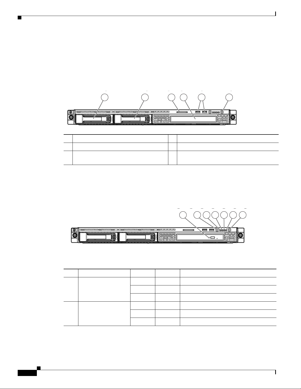
Figure 1-1 shows the front panel components.
Figure 1-1 Front Panel
1 2 3 4 5 6
1 Hard drive bay 1 (SATA device number 1) 4 12.7-mm optical drive bay
2 Hard drive bay 2 (blank) 5 USB connectors (2)
3 Serial label pull tab 6 Power On/Standby button and system power
Chapter 1 Introducing the Cisco MXE 3000
189136
LED
Figure 1-2 shows the front panel LEDs.
Figure 1-2 Front Panel LEDs
Table 1-1 describes the front panel LEDs and their functions.
Ta b l e 1-1 Front Panel LED Descriptions
LED Color State Description
1 12.7-mm optical drive
activity LED
Green On Drive activity is normal.
Amber On Drive failure has occurred.
- Off No drive activity exists.
2 UID button/LED Blue On Identification is activated.
Blue Flashing System is being remotely managed.
- Off Identification is deactivated.
7654321
189140
1-2
Hardware Installation Guide for Cisco Media Experience Engine 3000
OL-17000-01
Page 13
Chapter 1 Introducing the Cisco MXE 3000
Table 1-1 Front Panel LED Descriptions
LED Color State Description
3 Internal health LED Green On System health is normal.
4 NIC 1 link/activity
LED
5 NIC 2 link/activity
LED
6 Drive activity LED Green On Drive activity is normal.
7 Power On/Standby
button and system
power LED
Hardware Features
Amber On System health is degraded.
Red On System health is critical.
- Off System health is normal (when in standby
mode).
Green On Network link exists.
Green Flashing Network link and activity exist.
- Off No network link exists.
If power is off, the front panel LED is not
active. View the LEDs on the RJ-45
connector.
Green On Network link exists.
Green Flashing Network link and activity exist.
- Off No network link exists.
If power is off, the front panel LED is not
active. View the LEDs on the RJ-45
connector.
Amber On Drive failure has occurred.
- Off No drive activity exists.
Green On System is on.
Amber On System is shut down, but power is still
applied.
- Off Power cord is not attached or power supply
failure has occurred.
Back Panel Components and LEDs
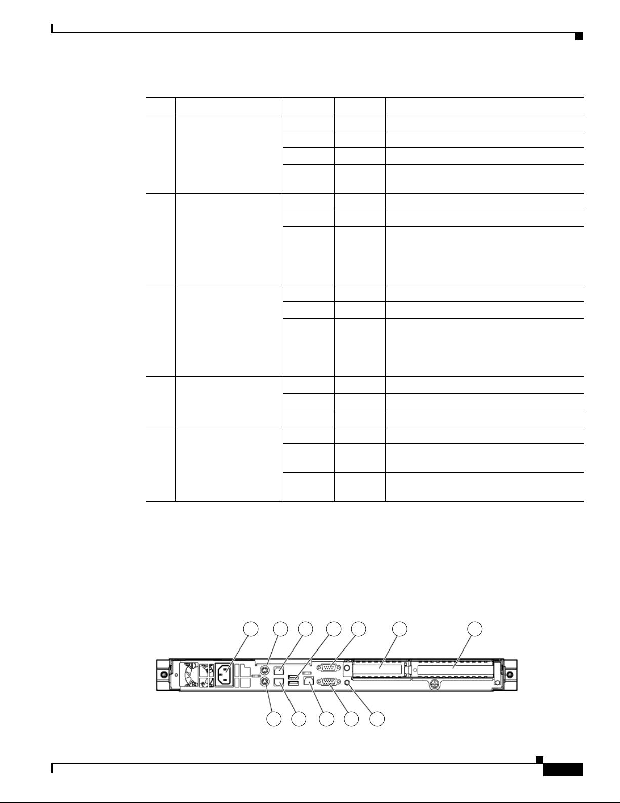
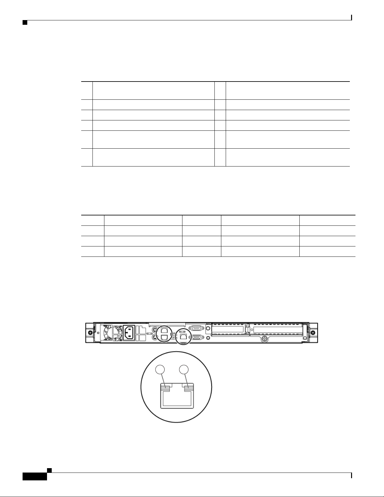
Figure 1-3 shows the back panel components.
Figure 1-3 Back Panel
1 42 3 5 6 7
OL-17000-01
180158
89101112
Hardware Installation Guide for Cisco Media Experience Engine 3000
1-3
Page 14
Hardware Features
Chapter 1 Introducing the Cisco MXE 3000
Table 1-2 identifies the back panel components.
Ta b l e 1-2 Back Panel Components
1 Power cord connector 7 PCI Express expansion slot 4, (optional
PCI-X), full-length
2 Mouse connector 8 UID button/LED
3 10/100/1000 NIC 2 connector 9 Video connector
4 USB connectors (2) 10 Dedicated iLO 2 management port (optional)
5 Serial connector 11 10/100/1000 NIC 1/shared iLO 2
management port
6 PCI Express expansion slot 5, low profile,
half-length
The Cisco MXE 3000 contains seven PCI expansion slots; however, slots 1, 2, 3, 6, and 7 are reserved.
Table 1-3 provides the PCI expansion slot definitions for slots 4 and 5.
12 Keyboard connector
Ta b l e 1-3 PCI Slot Definitions
Slot Ty pe Length Connector Interconnect
4 PCI Express Full x8 x8
4 Optional PCI-X Full 133 MHz/3.3. V 64 bit
5 PCI Express
1. The Cisco MXE 3000 supports x8 PCI Express cards, but these cards will run at x1 speeds.
1
Half x8 x1
Figure 1-4 shows the back panel LEDs.
Figure 1-4 Back Panel LEDs
189139
1 2
1-4
Hardware Installation Guide for Cisco Media Experience Engine 3000
OL-17000-01
Page 15
Chapter 1 Introducing the Cisco MXE 3000
Table 1-4 describes the back panel LEDs and their functions.
Ta b l e 1-4 Back Panel LEDs
LED Color State Description
1 NIC/iLO 2 activity Green On Activity exists.
2 NIC/iLO 2 link Green On Link exists.
Location of Ports and Connectors
The Cisco MXE 3000 appliance supports two Ethernet connectors on the back of the device. See
“Ethernet Port Connectors” section on page 1-5, for more information.
Figure 1-3 shows the back panel ports and connectors.
Hardware Features
Green Flashing
- Off No activity exists.
- Off No link exists.
Warning
To avoid electric shock, do not connect safety extra-low voltage (SELV) circuits to telephone-network
voltage (TNV) circuits. LAN ports contain SELV circuits, and WAN ports contain TNV circuits. Some
LAN and WAN ports both use RJ-45 connectors. Use caution when connecting cables.
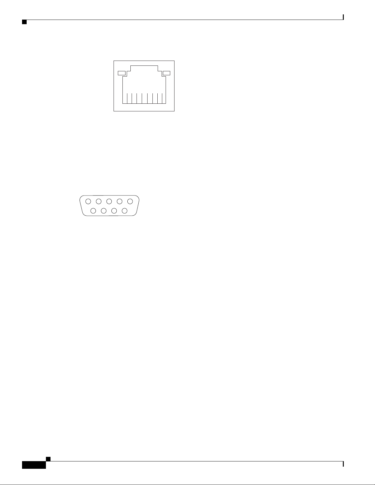
Ethernet Port Connectors
Connect a Category 3, 4, or 5 unshielded twisted-pair cable to an Ethernet connector (shown in
Figure 1-5). 100BASE-TX and 1000BASE-T Fast Ethernet standards require Category 5 or higher
cabling.
The Cisco MXE 3000 has three Ethernet connectors. Two of the Ethernet connectors are attached to the
Ethernet controllers and the third connector is the systems-management Ethernet connector, which is not
supported by the Cisco
The Ethernet controllers are integrated on the system board. They provide an interface for connecting to
a 10-Mbps, 100-Mbps, or 1-Gbps network and provide full-duplex (FDX) capability, which enables
simultaneous transmission and reception of data on the network. If the Ethernet ports in the appliance
support auto negotiation, the controllers detect the data-transfer rate (10BASE-T, 100BASE-TX, or
1000BASE-T) and duplex mode (full duplex or half duplex) of the network and automatically operate at
that rate and mode. You do not have to set any jumpers or configure the controllers.
If a problem occurs with the primary Ethernet connection, all Ethernet traffic associated with this
primary connection is automatically switched to the redundant Ethernet connection. If the applicable
device drivers are installed, switching occurs without data loss and without user intervention.
Statement 1021
MXE 3000 software.
OL-17000-01
Hardware Installation Guide for Cisco Media Experience Engine 3000
1-5
Page 16
System Board Components and LEDs
Figure 1-5 Ethern et Port Connector
Chapter 1 Introducing the Cisco MXE 3000
Activity LED
(green)
8
Link LED
(green)
83195
1
Serial Port Connector
The Cisco MXE 3000 has one serial port connector (shown in Figure 1-6). Use the serial port connector
to connect a serial device.
Figure 1-6 Serial Port Connector
1
69
5
83193
System Board Components and LEDs
This section shows where the system board components are located, LED functions, and describes the
system maintenance switch operating options.
This section contains the following topics:
• System Board Components, page 1-7
• System Board LEDs, page 1-8
• System Maintenance Switch, page 1-9
• System Board Fans, page 1-10
1-6
Hardware Installation Guide for Cisco Media Experience Engine 3000
OL-17000-01
Page 17
Chapter 1 Introducing the Cisco MXE 3000
System Board Components
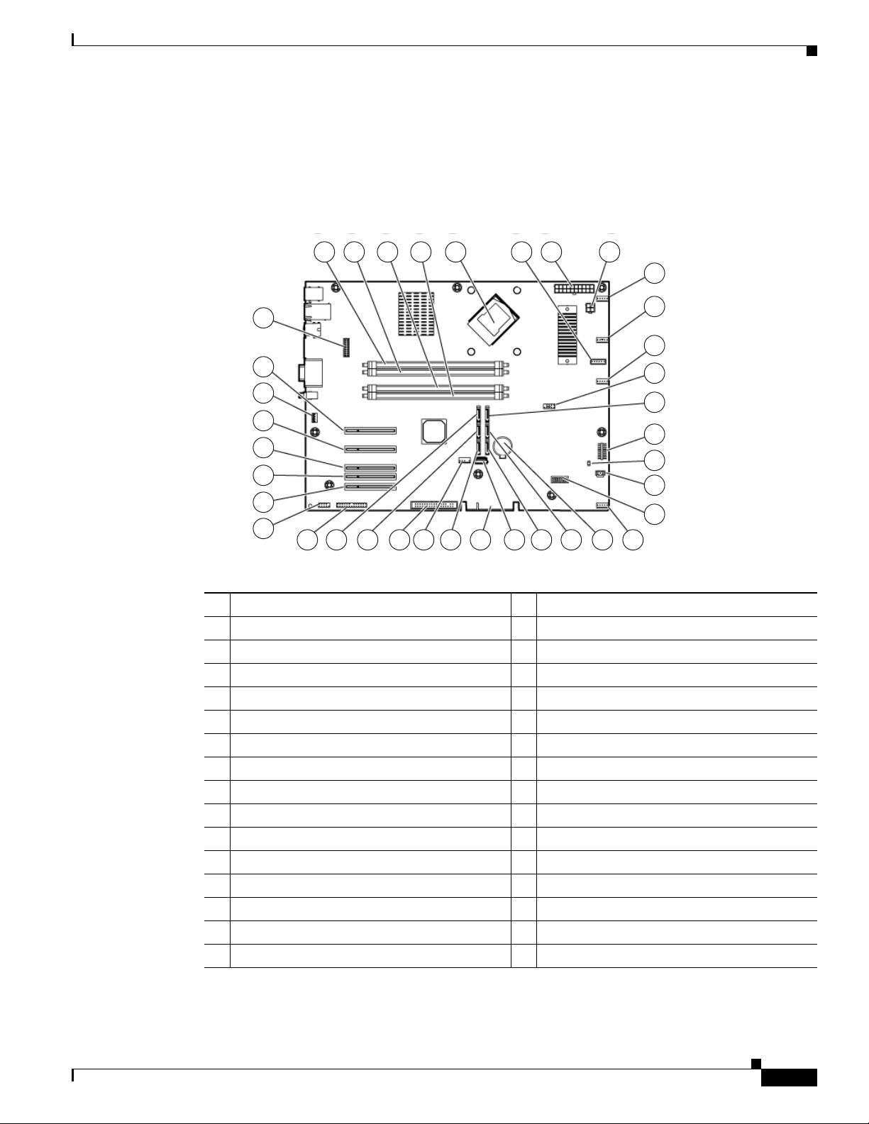
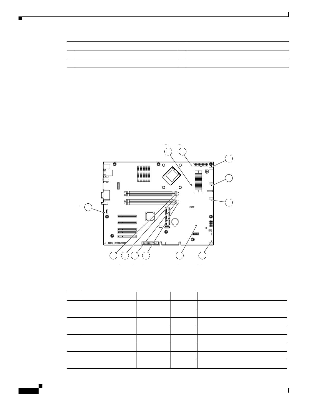
Figure 1-7 shows the layout of the system board components.
Figure 1-7 System Board Components
System Board Components and LEDs
1 2 3 4 6 7 8
5
9
10
37
11
36
35
12
13
34
14
33
15
32
16
31
17
30
29 2 27 26 25 24 23 22 21 20 19 18
189141
1 DIMM slot 1 (bank A) 20 SATA connector 4 (hard drive)
2 DIMM slot 2 (bank B) 21 SATA connector 6 (optical drive)*
3 DIMM slot 3 (bank C) 22 Reserved
4 DIMM slot 4 (bank D) 23 Reserved
5 Processor socket 24 SATA connector 5 (optical drive)*
6 Reserved 25 Internal USB option connector
7 System power connector 26 Reserved
8 Processor power connector 27 SATA connector 3 (hard drive)
9 Fan 1 connector 28 SATA connector 1 (hard drive)
10 Fan 2 connector 29 Parallel option connector
11 Fan 3 connector 30 Serial option connector
12 Front USB cable connector 31 Reserved
13 SATA connector 2 (hard drive) 32 PCI Express expansion slot 4
14 Front panel LED connector 33 PCI Express expansion slot 5**
15 NMI jumper 34 R served
16 Reserved 35 Reserved
OL-17000-01
Hardware Installation Guide for Cisco Media Experience Engine 3000
1-7
Page 18
System Board Components and LEDs
17 System maintenance switch 36 Reserved
18 Fan 4 connector 37 Dedicated iLO2 optional module connector
19 System battery — —
* The serve supports one optical drive that can be connected to either SATA connector 5 or SATA connector 6.
** x8 PCI Express cards are supported, but will run at x1 speeds.
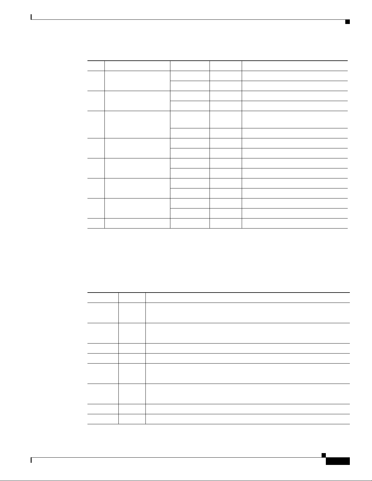
System Board LEDs
Figure 1-8 shows the system board LEDs.
Figure 1-8 System Board LEDs
Chapter 1 Introducing the Cisco MXE 3000
1 2
3
4
5
12
67891011
189142
Table 1-5 describes the system board LED functions.
Ta b l e 1-5 System Board LEDs
LED Color State Description
1 Processor error Amber On A multibit error has occurred.
- Off No activity exists.
2 PMM failure Amber On PPM has failed.
- Off Normal.
3 Fan 1 failure Amber On Fan 1 has failed or is missing.
- Off Normal.
4 Fan 2 failure Amber On Fan 2 has failed or is missing.
- Off Normal.
1-8
Hardware Installation Guide for Cisco Media Experience Engine 3000
OL-17000-01
Page 19
Chapter 1 Introducing the Cisco MXE 3000
Table 1-5 System Board LEDs (continued)
LED Color State Description
5 Fan 3 failure Amber On Fan 3 has failed or is missing.
6 PCI fan failure Amber On PCI fan has failed or is missing.
7 Overtemperature Amber On System has reached a cautionary or
8 DIMM 4 failure Amber On DIMM has failed or is missing.
9 DIMM 3 failure Amber On DIMM has failed or is missing.
10 DIMM 2 failure Amber On DIMM has failed or is missing.
11 DIMM 1 failure Amber On DIMM has failed or is missing.
12 Reserved - - -
System Board Components and LEDs
- Off Normal.
- Off Normal.
critical temperature level.
- Off Normal.
- Off Normal.
- Off Normal.
- Off Normal.
- Off Normal.
System Maintenance Switch
Table 1-6 describes the functions associated with each switch on the system maintenance switch (see
Item 17 of Figure 1-7).
Ta b l e 1-6 System Maintenance Switch
Position Default Function
S1 Off • Off = iLO 2 security is enabled
S2 Off • Off = Normal operation
S3 Off Reserved
S4 Off Reserved
S5 Off • Off = Power-on password enabled
S6 Off • Off = Normal operation
S7 Off Reserved
S8 Off Reserved
• On = iLO 2 security is disabled
• On = RBSU will not commit any configuration changes*
• On = Power-on password disabled*
• On = BIOS will clear CMOS and NVRAM*
OL-17000-01
Hardware Installation Guide for Cisco Media Experience Engine 3000
1-9
Page 20

System Board Components and LEDs
System Board Fans
Figure 1-9 shows the location of the system board fans that provide ventilation for the chassis.
Figure 1-9 System Board Fans
Chapter 1 Introducing the Cisco MXE 3000
189137
1-10
Hardware Installation Guide for Cisco Media Experience Engine 3000
OL-17000-01
Page 21

CHAP T ER
2
Preparing to Install the Cisco MXE 3000
This chapter contains important safety information that you should know before working with the
Cisco
MXE 3000. Use the guidelines in this chapter to ensure your own personal safety and to help
protect your appliance from potential damage.
This chapter contains the following sections:
• Safety Warnings and Cautions, page 2-1
• Safety Guidelines, page 2-2
• Environmental Requirements, page 2-4
• Power Requirements, page 2-5
• Grounding Requirements, page 2-5
Note Read the Regulatory Compliance and Safety Information for Cisco Media Experience Engine 3000
document that came with your appliance before you begin the installation.
Safety Warnings and Cautions
Before you install the Cisco MXE 3000, observe the following safety warnings and cautions:
Warning
Warning
OL-17000-01
Only authorized technicians trained should attempt to repair this equipment. All troubleshooting and
repair procedures are detailed to allow only subassembly/module-level repair. Because of the
complexity of the individual boards and subassemblies, no one should attempt to make repairs at the
component level or to make modifications to any printed wiring board. Improper repairs can create a
safety hazard.
To reduce the risk of personal injury or damage to the equipment, be sure that: - The leveling feet are
extended to the floor.
- The full weight of the rack rests on the leveling feet.
- The stabilizing feet are attached to the rack if it is a single-rack installation. - The racks are coupled
together in multiple-rack installations.
- Only one component is extended at a time. A rack may become unstable if more than one component
is extended for any reason.
Hardware Installation Guide for Cisco Media Experience Engine 3000
2-1
Page 22

Safety Guidelines
Chapter 2 Preparing to Install the Cisco MXE 3000
Warning
Warning
Caution To properly ventilate the system, you must provide at least 7.6 cm (3.0 in) of clearance at the front and
To reduce the risk of electric shock or damage to the equipment:
- Do not disable the power cord grounding plug. The grounding plug is an important safety feature.
- Plug the power cord into a grounded (earthed) electrical outlet that is easily accessible at all times.
- Unplug the power cord from the power supply to disconnect power to the equipment.
- Do not route the power cord where it can be walked on or pinched by items placed against it. Pay
particular attention to the plug, electrical outlet, and the point where the cord extends from the server.
To reduce the risk of personal injury or damage to the equipment:
- Observe local occupation health and safety requirements and guidelines for manual handling.
- Obtain adequate assistance to lift and stabilize the chassis during installation or removal. The
server is unstable when not fastened to the rails. When mounting the server in a rack, remove the
power supplies and any other removable module to reduce the overall weight of the product.
back of the server.
Caution The server is designed to be electrically grounded (earthed). To ensure proper operation, plug the AC
power cord into a properly grounded AC outlet only.
Safety Guidelines
To reduce the risk of bodily injury, electrical shock, fire, and damage to the equipment, observe the
precautions in this section.
This section contains the following topics:
• General Precautions, page 2-2
• System Reliability Considerations, page 2-3
• Working Inside the Cisco MXE 3000 with the Power On, page 2-4
• Protecting Against Electrostatic Discharge, page 2-4
General Precautions
Observe the following general precautions for using and working with the Cisco MXE 3000:
• Observe and follow service markings. Do not service any Cisco product except as explained in your
system documentation. Opening or removing covers that are marked with the triangular symbol with
a lightning bolt may expose you to electrical shock. Components inside these compartments should
be serviced only by a trained and qualified service technician.
• If any of the following conditions occur, unplug the product from the electrical outlet and replace
the part or contact your customer service representative:
–
The power cable or plug is damaged.
–
An object has fallen into the product.
2-2
Hardware Installation Guide for Cisco Media Experience Engine 3000
OL-17000-01
Page 23

Chapter 2 Preparing to Install the Cisco MXE 3000
–
The product has been exposed to water.
–
The product has been dropped or damaged.
–
The product does not operate correctly when you follow the operating instructions.
• Keep your system components away from radiators and heat sources. Also, do not block cooling
vents.
• Do not spill food or liquids on your system components, and never operate the product in a wet
environment.
• Do not push any objects into the openings of your system components. Doing so can cause fire or
electric shock by shorting out interior components.
• Use the product only with other Cisco-approved equipment.
• Allow the product to cool before removing covers or touching internal components.
• Use the correct external power source. Operate the product only from the type of power source
indicated on the electrical ratings label. If you are not sure of the type of power source required,
consult your service representative or local power company.
• Use only approved power cables. If you have not been provided with a power cable for your
Cisco
MXE 3000 or for any AC-powered option intended for your system, purchase a power cable
that is approved for use in your country. The power cable must be rated for the product and for the
voltage and current marked on the product’s electrical ratings label. The voltage and current rating
of the cable should be greater than the ratings marked on the product.
• To help prevent electric shock, plug the system components and peripheral power cables into
properly grounded electrical outlets. These cables are equipped with three-prong plugs to help
ensure proper grounding. Do not use adapter plugs or remove the grounding prong from a cable.
Safety Guidelines
• Observe power strip ratings. Make sure that the total ampere rating of all products plugged into the
power strip does not exceed 80 percent of the power strip ampere ratings limit.
• Do not use appliance or voltage converters or kits sold for appliances with your product.
• To help protect your system components from sudden, transient increases and decreases in electrical
power, use a surge suppressor, line conditioner, or uninterruptible power supply (UPS).
• Position cables and power cords carefully; route cables and the power cord and plug so that they
cannot be stepped on or tripped over. Be sure that nothing rests on your system components’ cables
or power cord.
• Do not modify power cables or plugs. Consult a licensed electrician or your power company for site
modifications. Always follow your local or national wiring rules.
System Reliability Considerations
To help ensure proper cooling and system reliability, make sure the following occurs:
• Each of the drive bays has either a drive or a filler panel installed.
• For rack configurations, make sure that space is available around the appliance to enable the cooling
system to work properly. See the
information.
• A removed hot-swappable drive is replaced within 2 minutes of removal.
• A failed fan is replaced within 48 hours.
“Environmental Requirements” section on page 2-4, for additional
OL-17000-01
Hardware Installation Guide for Cisco Media Experience Engine 3000
2-3
Page 24

Chapter 2 Preparing to Install the Cisco MXE 3000
Environmental Requirements
Working Inside the Cisco MXE 3000 with the Power On
The Cisco MXE 3000 is designed to operate safely with the cover removed for short periods (less than
30
minutes). You might need to remove the cover while the power is on, for example, to observe the
diagnostic LEDs when troubleshooting. When you work inside an appliance that is powered on, follow
these guidelines:
• Avoid loose-fitting clothing on your forearms. Button long-sleeved shirts before working inside the
appliance; do not wear cuff links while you are working inside the appliance.
• Do not allow your necktie or scarf to hang inside the appliance.
• Remove jewelry, such as bracelets, necklaces, rings, and loose-fitting wristwatches.
• Remove items from your shirt pocket (such as pens or pencils) that could fall into the appliance as
you lean over it.
• Do not drop any metallic objects, such as paper clips, hairpins, or screws, into the appliance.
• Be aware that there are hazardous moving parts exposed inside the appliance when the cover is
removed.
Protecting Against Electrostatic Discharge
Static electricity can harm delicate components inside the appliance. To prevent static damage, discharge
static electricity from your body before you touch any of your system’s electronic components. You can
do so by touching an unpainted metal surface on the chassis.
You can also take the following steps to prevent damage from electrostatic discharge (ESD):
• When unpacking a static-sensitive component from its shipping carton, do not remove the
component from the antistatic packing material until you are ready to install the component in your
system. Just before unwrapping the antistatic packaging, be sure to discharge static electricity from
your body.
• When transporting a sensitive component, first place it in an antistatic container or packaging.
• Handle all sensitive components in a static-safe area. If possible, use antistatic floor pads and
workbench pads.
• Handle the device carefully, holding it by its edges or its frame.
• Do not touch solder joints, pins, or exposed printed circuitry.
• Do not leave the device where others can handle and possibly damage the device.
• Take additional care when handling devices during cold weather, because heating reduces indoor
humidity and increases static electricity.
Environmental Requirements
2-4
To ensure continued safe and reliable equipment operation, install or position the system in a
well-ventilated, climate-controlled environment.
The maximum recommended ambient operating temperature (TMRA) for most server products is 35°C
(95°F). The temperature in the room where the rack is located must not exceed 35°C (95°F).
For details about the Cisco MXE 3000 environmental requirements, see Appendix A, “Cisco MXE 3000
Hardware Specifications.”
Hardware Installation Guide for Cisco Media Experience Engine 3000
OL-17000-01
Page 25

Chapter 2 Preparing to Install the Cisco MXE 3000
Power Requirements
Installation of this equipment must comply with local and regional electrical regulations governing the
installation of information technology equipment by licensed electricians. This equipment is designed
to operate in installations covered by NFPA 70, 1999 Edition (National Electric Code) and NFPA-75,
1992 (code for Protection of Electronic Computer/Data Processing Equipment).
Power Requirements
Warning
Caution Protect the server from power fluctuations and temporary interruptions with a regulating uninterruptible
To reduce the risk of personal injury, fire, or damage to the equipment, do not overload the AC supply
branch circuit that provides power to the rack. Consult the electrical authority having jurisdiction
over wiring and installation requirements of your facility.
power supply (UPS). This device protects the hardware from damage caused by power surges and
voltage spikes and keeps the system in operation during a power failure.
When installing more than one server, you may need to use additional power distribution devices to
safely provide power to all devices. Observe the following guidelines:
• Balance the server power load between available AC supply branch circuits.
• Do not allow the overall system AC current load to exceed 80 percent of the branch circuit AC
current rating.
• Do not use common power outlet strips for this equipment.
• Provide a separate electrical circuit for the server.
For details about the Cisco MXE 3000 power requirements, see Appendix A, “Cisco MXE 3000
Hardware Specifications.”
Grounding Requirements
OL-17000-01
To ensure proper operation and safety, you must properly ground the server. In the United States, install
the equipment in accordance with NFPA 70, 1999 Edition (National Electric Code), Article 250, as well
as any local and regional building codes. In Canada, you must install the equipment in accordance with
Canadian Standards Association, CSA C22.1, Canadian Electrical Code. In all other countries, you must
install the equipment in accordance with any regional or national electrical wiring codes, such as the
International Electrotechnical Commission (IEC) Code 364, parts 1 through 7. Furthermore, you must
be sure that all power distribution devices used in the installation, such as branch wiring and receptacles,
are listed or certified grounding-type devices.
Because of the high ground-leakage currents associated with multiple servers connected to the same
power source, we recommend the use of a PDU that is either permanently wired to the building's branch
circuit or includes a nondetachable cord that is wired to an industrial-style plug. NEMA locking-style
plugs or those complying with IEC 60309 are considered suitable for this purpose. Using common power
outlet strips for the server is not recommended.
Hardware Installation Guide for Cisco Media Experience Engine 3000
2-5
Page 26

Grounding Requirements
Chapter 2 Preparing to Install the Cisco MXE 3000
2-6
Hardware Installation Guide for Cisco Media Experience Engine 3000
OL-17000-01
Page 27

Warning
CHAP T ER
3
Installing the Cisco MXE 3000
This chapter describes how to install a Cisco MXE 3000 in an equipment rack. This chapter contains the
following sections:
• Rack-Mounting Parts, Tools, and Considerations, page 3-2
• Rack Mounting and Cabling the Cisco MXE 3000, page 3-3
• Connecting Power and Booting the System, page 3-3
• Checking the LEDs, page 3-4
Before you begin the installation, read Chapter 2, “Preparing to Install the Cisco MXE 3000” and the
Regulatory Compliance and Safety Information for Cisco Media Experience Engine 3000 document.
Read the installation instructions before connecting the system to the power source.
Statement 1004.
OL-17000-01
Hardware Installation Guide for Cisco Media Experience Engine 3000
3-1
Page 28

Chapter 3 Installing the Cisco MXE 3000
Rack-Mounting Parts, Tools, and Considerations
Rack-Mounting Parts, Tools, and Considerations
A rack mounting hardware kit is included in your shipping container. To mount the Cisco MXE 3000 in
the rack, you need a T-10/T-15 Torx screwdriver.
Warning
To prevent bodily injury when mounting or servicing this unit in a rack, you must take special
precautions to ensure that the system remains stable. The following guidelines are provided to ensure
your safety:
• This unit should be mounted at the bottom of the rack if it is the only unit in the rack.
• When mounting this unit in a partially filled rack, load the rack from the bottom to the top with the heaviest
component at the bottom of the rack.
• If the rack is provided with stabilizing devices, install the stabilizers before mounting or servicing the unit in the
rack.
Statement 1006
To allow for servicing and adequate airflow, observe the following space and airflow requirements when
deciding where to install a rack:
• Leave a minimum clearance of 63.5 cm (25 in) in front of the rack.
• Leave a minimum clearance of 76.2 cm (30 in) behind the rack.
• Leave a minimum clearance of 121.9 cm (48 in) from the back of the rack to the back of another
rack or row of racks.
The Cisco MXE 3000 draw in cool air through the front door and expel warm air through the rear door.
Therefore, the front and rear rack doors must be adequately ventilated to allow ambient room air to enter
the cabinet, and the rear door must be adequately ventilated to allow the warm air to escape from the
cabinet.
3-2
Caution To prevent improper cooling and damage to the equipment, do not block the ventilation openings.
When vertical space in the rack is not filled by a appliance or rack component, the gaps between the
components cause changes in airflow through the rack and across the appliances. Cover all gaps with
blanking panels to maintain proper airflow.
Caution Always use blanking panels to fill empty vertical spaces in the rack. This arrangement ensures proper
airflow. Using a rack without blanking panels results in improper cooling that can lead to thermal
damage.
Hardware Installation Guide for Cisco Media Experience Engine 3000
OL-17000-01
Page 29

Chapter 3 Installing the Cisco MXE 3000
Rack Mounting and Cabling the Cisco MXE 3000
Observe the following additional requirements to ensure adequate airflow and to prevent damage to the
equipment:
• Front and rear doors—If the 42U rack includes closing front and rear doors, you must allow 5,350
sq cm (830 sq in) of holes evenly distributed from top to bottom to permit adequate airflow
(equivalent to the required 64 percent open area for ventilation).
• Side—The clearance between the installed rack component and the side panels of the rack must be
a minimum of 7 cm (2.75 in).
Rack Mounting and Cabling the Cisco MXE 3000
To install the appliance into a rack with square, round, or threaded holes, refer to the instructions that
ship with the rack hardware kit.
If you are installing the appliance into a telco rack, order the appropriate option kit from the
manufacturer and follow the instructions that shipped with the product to install the rack brackets.
Refer to Figure 1-3 on page 1-3 when connecting peripheral cables and power cords to the appliance.
Warning
To reduce the risk of electric shock, fire, or damage to the equipment, do not plug telephone or
telecommunications connectors into RJ-45 connectors.
Connecting Power and Booting the System
To connect power to your system, follow these steps:
Step 1 Review the information in the “Safety Guidelines” section on page 2-2.
Step 2 Plug a power cord into each power cord receptacle on the back of the appliance.
Step 3 Connect the other end of each power cord to a power source at your installation site.
Step 4 Power up all externally connected devices.
Step 5 Press the power control button on the front of the appliance.
The system should begin booting. Once the operating system boots, you are ready to initialize the basic
software configuration. See the Deployment and Administration Guide for Cisco
Engine
3000 on Cisco.com for more information.
Note While powering up, the green power-on LED on the front of the appliance is on.
Media Experience
Checking the LEDs
When the Cisco MXE 3000 is up and running, observe the front panel LEDs (see Figure 1-2 on page 1-2
and Table 1-1 on page 1-2) to verify that your system is operating properly.
To troubleshoot using the LEDs, see Chapter 5, “Troubleshooting the Cisco MXE 3000.”
OL-17000-01
Hardware Installation Guide for Cisco Media Experience Engine 3000
3-3
Page 30

Checking the LEDs
Chapter 3 Installing the Cisco MXE 3000
3-4
Hardware Installation Guide for Cisco Media Experience Engine 3000
OL-17000-01
Page 31

Installing Hardware Options for the Cisco MXE 3000
This chapter provides basic instructions for installing hardware options in your Cisco MXE 3000.
Note These instructions are intended for technicians who are experienced with setting up Cisco MXE 3000
hardware.
This chapter contains the following sections:
• Removing the Cover, page 4-1
• Removing a Hard Drive Blank, page 4-2
Removing the Cover
CHAP T ER
4
OL-17000-01
Warning
Step 1 Review the information in the “Safety Warnings and Cautions” section on page 2-1 and the “Safety
Step 2 Power off the device and all attached devices and disconnect all external cables and power cords.
Step 3 Press down on the left and right side latches and pull the device out of the rack enclosure until both slide
Step 4 Lift the cover-release latch. Lift the cover off the device and set the cover aside.
Caution For proper cooling and airflow, replace the cover before turning on the device. Operating the device for
Before working on a system that has an on/off switch, turn OFF the power and unplug the power cord.
Statement 1
To remove the device top cover, follow these steps:
Guidelines” section on page 2-2.
rails lock.
Note You can reach the cables on the back of the device when the device is in the locked position.
extended periods (over 30 minutes) with the cover removed might damage device components.
Hardware Installation Guide for Cisco Media Experience Engine 3000
4-1
Page 32

Removing a Hard Drive Blank
Removing a Hard Drive Blank
Caution To prevent improper cooling and thermal damage, do not operate the server unless all bays are populated
with either a component or a blank.
Remove the component, as shown in Figure 4-1.
Figure 4-1 Removing a Hard Drive Blank
Chapter 4 Installing Hardware Options for the Cisco MXE 3000
4-2
Hardware Installation Guide for Cisco Media Experience Engine 3000
OL-17000-01
Page 33

CHAP T ER
5
Troubleshooting the Cisco MXE 3000
This chapter provides basic troubleshooting information to help you identify some common problems
that might occur with your Cisco
This chapter contains the following sections:
• Identifying System Problems, page 5-2
• Checking Connections and Switches, page 5-2
• Power-On Self Test (POST), page 5-3
• NMI Functionality, page 5-11
• Trouble Indicators and Status LEDs, page 5-11
• System LEDs and Internal Health LED Combinations, page 5-11
• Troubleshooting Undetermined Problems, page 5-12
• General Problem-Solving Tips, page 5-13
• Collecting Information for Technical Support, page 5-15
Use the information in this chapter to determine whether a problem originates with the hardware or the
software. For further assistance, contact your customer service representative.
MXE 3000.
OL-17000-01
Note The keyboard and mouse are supported by the BIOS for power-on self-test (POST) and the diagnostic
programs that are located in the device ROM.
When console redirection is enabled, all the tests available from a keyboard are accessible through the
console connection as well. (Mouse support, however, is not available through the console connection.)
You can run all the diagnostics and tests that are supported by the BIOS, with a few exceptions. Tests for
ports that are not supported by the Cisco
Caution Components that are not orderable as spare hardware options can only be replaced by a qualified service
technician. Once you have identified a faulty component, contact the Cisco Technical Assistance Center
(TAC).
Note Read the “Working Inside the Cisco MXE 3000 with the Power On” section on page 2-4 before opening
the chassis cover.
Hardware Installation Guide for Cisco Media Experience Engine 3000
MXE 3000 software are invalid.
5-1
Page 34

Identifying System Problems
Identifying System Problems
To identify system problems, follow these steps:
Step 1 Check the power LED.
Step 2 Power down the device and all external devices.
Step 3 Check all cables and power cords. (See the “Checking Connections and Switches” section on page 5-2.)
Step 4 Set all display controls on the terminal or display device to the middle position.
Step 5 Power up all external devices.
Step 6 Power up the device.
Step 7 Record any POST error messages that are displayed on the screen. If an error is displayed, look up the
first error in the
Step 8 If the diagnostic programs were completed successfully and you still suspect a problem, see the
“Troubleshooting Undetermined Problems” section on page 5-12.
Step 9 Check the system error log to see if an error was recorded by the system.
“POST Error Codes” section on page 5-4.
Chapter 5 Troubleshooting the Cisco MXE 3000
Checking Connections and Switches
Improperly set switches and controls and loose or improperly connected cables are the most likely source
of problems for the chassis or other external equipment. A quick check of all
cable connections can easily solve
controls and indicators. See Figure 1-3 for the location of back panel connectors on the system.)
To check all the connections and switches, follow these steps:
Step 1 Power down the system, including any attached peripherals such as external drives. Disconnect all the
power cables from their electrical outlets.
Step 2 If the system is connected to a power strip (or power distribution unit), turn the power strip off and then
on again.
Is the power strip receiving power?
Ye s . Go to Step 5.
No. Go to Step 3.
Step 3 Plug the power strip into another electrical outlet.
Is the power strip receiving power?
Ye s . The original electrical outlet probably does not function. Use a different electrical outlet.
No. Go to Step 4.
Step 4 Plug a system that you know works into the electrical outlet.
Does the system receive power?
Ye s . The power strip is probably not functioning properly. Use another power strip.
these problems. (See Figure 1-1 for the location of front panel
the switches, controls, and
5-2
No. Go to Step 5.
Hardware Installation Guide for Cisco Media Experience Engine 3000
OL-17000-01
Page 35

Chapter 5 Troubleshooting the Cisco MXE 3000
Step 5 Reconnect the system to the electrical outlet or power strip.
Make sure that all connections fit tightly together.
Step 6 Power up the system.
Is the problem resolved?
Ye s . The connections were loose. You have fixed the problem.
No. Call your customer service representative. (See the “Obtaining Documentation and Submitting a
Service Request” section on page x.)
Power-On Self Test (POST)
This section describes the power-on self test (POST) and the POST error codes and messages.
This section contains the following topics:
• POST Overview, page 5-3
• POST Error Codes, page 5-4
Power-On Self Test (POST)
POST Overview
When you power up the device, it performs a series of tests to check the operation of device components
and some of the hardware options installed in the device. This series of tests is called the power-on
self-test, or POST.
If POST finishes without detecting any problems, a single beep sounds, and the first screen of your
operating system or application program appears.
If POST detects a problem, more than one beep sounds, and an error message appears on your screen.
See the
Note If you have a power-up password or administrator password set, you must enter the password and press
Enter when prompted, before POST will continue.
Note A single problem might cause several error messages. When this situation occurs, you should correct the
cause of the first error message. After you correct the cause of the first error message, the other error
messages usually will not occur the next time that you run the test.
The POST error log contains the three most recent error codes and messages that the system generated
during POST. The system error log contains all messages issued during POST and all system status
messages from the service processor.
You can view the contents of the system error log from the diagnostic programs.
“POST Error Codes” section on page 5-4 for more information.
OL-17000-01
Hardware Installation Guide for Cisco Media Experience Engine 3000
5-3
Page 36

Power-On Self Test (POST)
POST Error Codes
The error messages and codes in this section include all messages generated by the Cisco MXE 3000
appliance. Some messages are informational only and do not indicate any error. A server generates only
the codes that are applicable to its configuration and options.
Chapter 5 Troubleshooting the Cisco MXE 3000
Warning
To avoid potential problems, ALWAYS read the warnings and cautionary information in the server
documentation before removing, replacing, reseating, or modifying system components
Advanced Memory Protection mode: Advanced ECC
Possible Cause: Advanced ECC support is enabled.
Action: None.
Advanced Memory Protection mode: Advanced ECC with hot-add support
Possible Cause: Advanced ECC with Hot-Add support is enabled.
Action: None.
Advanced Memory Protection mode: Online spare with Advanced ECC
...Xxxx MB System memory and xxxx MB memory reserved for Online Spare.
Possible Cause: This message indicates Online Spare Memory is enabled and indicates the amount of
memory reserved for this feature.
Action: None.
Advanced Memory Protection mode: Multi-board mirrored memory with Advanced ECC
...Xxxx MB System memory and xxxx MB memory reserved for Mirroring.
Possible Cause: This message indicates Mirrored Memory is enabled and indicates the amount of
memory reserved for this feature.
Action: None.
Advanced Memory Protection mode: RAID memory with Advanced ECC
...Xxxx MB System memory and xxxx MB memory reserved for RAID.
Possible Cause: This message indicates RAID Memory is enabled and indicates the amount of memory
reserved for this feature.
Action: None.
An Unexpected Shutdown occurred prior to this power-up
Possible Cause: The server shut down because of an unexpected event on the previous boot.
Action: Check the System Management Log or OS Event Log for details on the failure.
Critical Error Occurred Prior to this Power-Up
Possible Cause: A catastrophic system error, which caused the server to crash, has been logged.
Action: If the problem persists contact your Cisco representative to arrange for repair.
Hardware Installation Guide for Cisco Media Experience Engine 3000
5-4
OL-17000-01
Page 37

Chapter 5 Troubleshooting the Cisco MXE 3000
Fan Solution Not Fully Redundant
Possible Cause: The minimum number of required fans is installed, but some redundant fans are missing
or failed.
Action: Install fans or replace failed fans to complete redundancy.
Fan Solution Not Sufficient
Possible Cause: The minimum number of required fans is missing or failed.
Action: Install fans or replace any failed fans.
Fatal DMA Error
Possible Cause: The DMA controller has experienced a critical error that has caused an NMI.
Action: If the problem persists contact your Cisco representative to arrange for repair.
Fatal Express Port Error
Possible Cause: A PCI Express port has experienced a fatal error that caused an NMI.
Power-On Self Test (POST)
Action: Reseat any loose PCI Express boards. If the problem persists contact your Cisco representative
to arrange for repair.
Fatal Front Side Bus Error
Possible Cause: The processor front-side bus experienced a fatal error.
Action: Reseat any loose processors. If the problem persists contact your Cisco representative to arrange
for repair.
Fatal Global Protocol Error
Possible Cause: The system experienced a critical error that caused an NMI.
Action: If the problem persists contact your Cisco representative to arrange for repair.
Fatal Hub Link Error
Possible Cause: The hub link interface has experienced a critical failure that caused an NMI.
Action: If the problem persists contact your Cisco representative to arrange for repair.
FATAL ROM ERROR: The System ROM is not Properly Programmed.
Possible Cause: The System ROM is not properly programmed.
Action: Replace the physical ROM part.
Fibre Channel Mezzanine/Balcony Not Supported.
Description: The Fibre Channel adapter is not supported on the server.
Action: Install the supported Fibre Channel adapter.
OL-17000-01
Hardware Installation Guide for Cisco Media Experience Engine 3000
5-5
Page 38

Power-On Self Test (POST)
High Temperature Condition detected by Processor X
Possible Cause: Ambient temperature exceeds recommended levels, fan solution is insufficient, or fans
have failed.
Action: Adjust the ambient temperature, install fans, or replace the failed fans.
Illegal Opcode - System Halted
Possible Cause: The server has entered the Illegal Operator Handler because of an unexpected event.
This error is often software-related and does not necessarily indicate a hardware issue.
Action: Be sure that all software is installed properly. If the problem persists contact your Cisco
representative to arrange for repair.
iLO Generated NMI
Possible Cause: The iLO controller generated an NMI.
Action: Check the iLO logs for details of the event.
Internal CPU Check - Processor
Chapter 5 Troubleshooting the Cisco MXE 3000
Possible Cause: A processor has experienced an internal error.
Action: If the problem persists contact your Cisco representative to arrange for repair.
Invalid memory types were found on the same node. Please check DIMM compatibility. - Some DIMMs may not be used
Description: Invalid or mixed memory types were detected during POST.
Action: Use only supported DIMM pairs when populating memory sockets. Refer to the applicable
server user guide memory requirements.
Invalid Password - System Halted!
Possible Cause: An invalid password was entered.
Action: Enter a valid password to access the system.
Invalid Password - System Restricted!
Possible Cause: A valid password that does not have permissions to access the system has been entered.
Action: Enter a valid password with the correct permissions.
Memory found on unpopulated Node. — Processor is required to be installed for memory to be used.
Description: The system detects DIMMs, but is unable to use the DIMMs because a processor is not
installed in the corresponding socket.
Action: To use the installed DIMMs, install a processor in the corresponding socket.
Mixed processor speeds detected. Please make sure that all processors are the same speed. — System Halted!
Description: Mixed processor speeds are not supported.
Action: Refer to the server documentation for supported processors. Be sure that all installed processors
are the same speed.
Hardware Installation Guide for Cisco Media Experience Engine 3000
5-6
OL-17000-01
Page 39

Chapter 5 Troubleshooting the Cisco MXE 3000
Network Server Mode Active and No Keyboard Attached
Possible Cause: A keyboard is not connected. An error has not occurred, but a message is displayed to
indicate the keyboard status.
Action: No action is required.
NMI - Button Pressed!
Possible Cause: The NMI button was pressed, initiating a memory dump for crash dump analysis.
Action: Reboot the server.
NMI - Undetermined Source
Possible Cause: An NMI event has occurred.
Action: Reboot the server.
Node Interleaving disabled - Invalid memory configuration
Description: Each node must have the same memory configuration to enable interleaving.
Power-On Self Test (POST)
No Floppy Drive Present
Step 1 Power down the server.
Step 2 Replace a failed diskette drive.
Step 3 Be sure a diskette drive is cabled properly, if a diskette drive exists.
No Keyboard Present
Step 1 1. Power down the server, and then reconnect the keyboard.
Step 2 2. Be sure no keys are depressed or stuck.
Step 3 3. If the failure reoccurs, replace the keyboard.
Action: Populate each node with the same memory configuration and enable interleaving in RBSU.
Possible Cause: No diskette drive is installed or a diskette drive failure has occurred.
Action:
Possible Cause: A keyboard is not connected to the server or a keyboard failure has occurred.
Action:
Parity Check 2 - System DIMM Memory
Possible Cause: An uncorrectable error memory event occurred in a memory DIMM.
Action: Use the DIMM LEDs to identify failed DIMMs and replace the DIMMs. If the problem persists
contact your Cisco representative to arrange for repair.
OL-17000-01
Hardware Installation Guide for Cisco Media Experience Engine 3000
5-7
Page 40

Power-On Self Test (POST)
PCI Bus Parity Error, PCI Slot x
Possible Cause: A PCI device has generated a parity error on the PCI bus.
Action: For plug-in PCI cards, remove the card. For embedded PCI devices, run Insight Diagnostics and
replace any failed components as indicated.
Power Fault Detected in Hot-Plug PCI Slot x
Possible Cause: PCI-X Hot Plug expansion slot was not powered up properly.
Action: Reboot the server.
Processor X Unsupported Wattage.
Possible cause: Processor not supported by current server.
Action: Refer to the server documentation for supported processors. If the processor is supported,
remove the processor, update the system to latest ROM, and then reinstall the processor.
Redundant ROM Detected - This system contains a valid backup system ROM.
Chapter 5 Troubleshooting the Cisco MXE 3000
Possible Cause: The system recognizes both the system ROM and redundant ROM as valid. This is not
an error.
Action: None
REDUNDANT ROM ERROR: Backup ROM Invalid. - ......run ROMPAQ to correct error condition.
Possible Cause: The backup system ROM is corrupted. The primary ROM is valid.
Action: Run ROMPaq Utility to flash the system so that the primary and backup ROMs are valid.
REDUNDANT ROM ERROR: Bootblock Invalid. - ...
...contact Your Representative.
Possible Cause: ROM bootblock is corrupt.
Action: Contact an authorized service provider.
REDUNDANT ROM ERROR: Primary ROM invalid. Booting Backup ROM. -...
...run ROMPAQ to correct error condition
Possible Cause: The primary system ROM is corrupt. The system is booting from the redundant ROM.
Action: Run ROMPaq Utility to restore the system ROM to the correct version.
Temperature violation detected - system Shutting Down in x seconds
Possible Cause: The system has reached a cautionary temperature level and is shutting down in X
seconds.
Action: Adjust the ambient temperature, install fans, or replace any failed fans.
There must be a first DIMM in pair if second DIMM in pair is populated. Second DIMM in pair ignored.
Description: The first DIMM socket in the pair is not populated. The second DIMM in the pair is not
recognized or used.
Hardware Installation Guide for Cisco Media Experience Engine 3000
5-8
OL-17000-01
Page 41

Chapter 5 Troubleshooting the Cisco MXE 3000
Power-On Self Test (POST)
Action: Populate the DIMM socket.
This system only supports 667 MHz Front Side Bus Speed Processors. One or more 800 MHz Front Side Bus Speed Processors
have been initialized at 667 MHz. System Halted!
Possible cause: One or more 800-MHz front side bus speed processors have been initialized at 667-MHz.
Action: Correct the processor configuration.
Unsupported DIMM(s) found in system. - DIMM(s) may not be used
Description: Unsupported memory types found in system.
Action: Refer to the applicable server user guide memory requirements and replace with supported
DIMMs.
Unsupported PCI Card Detected Remove PCI Card from Slot
Possible cause: The PCI card installed in the slot referenced in the message is strictly not supported on
this system.
Action: Remove the card from the slot reported in the message.
Unsupported Processor Detected System will ONLY boot ROMPAQ Utility. System Halted.
Possible Cause: Processor and/or processor stepping is not supported by the current system ROM.
Action: Refer to the server documentation for supported processors. If a ROM version exists that
supports the processor,
Step 1 Power down the server.
Step 2 Insert a Systems ROMPAQ diskette containing the latest ROM version.
Step 3 Boot the system to flash the system to the latest ROM version. Allow 15 minutes for the process to
complete. Successful completion is indicated by a series of beeps of increasing pitch.
WARNING: A Type 2 Header PCI Device Has Been Detected...
The BIOS will not configure this card. It must be configured properly by the OS or driver.
Possible Cause: Only Type 0 and Type 1 Header PCI Devices are configured by the system ROM. The
device will not work unless the OS or device driver properly configure the card. Typically this message
only occurs when PCI cards with a PCI to PCMCIA bridge are installed.
Action: Refer to the operating system documentation or the device driver information that ships with the
Type 2 PCI device.
WARNING - Mixed Stepping Processors were detected. System cannot proceed.
301-Keyboard Error
OL-17000-01
Possible cause: One or more 800-MHz front side bus speed processors have been initialized at 667-MHz.
Action: Correct the processor configuration.
Possible Cause: Keyboard failure occurred.
Hardware Installation Guide for Cisco Media Experience Engine 3000
5-9
Page 42

Power-On Self Test (POST)
Action:
Step 1 Power down the server, and then reconnect the keyboard.
Step 2 Be sure no keys are depressed or stuck.
Step 3 If the failure reoccurs, replace the keyboard.
301-Keyboard Error or Test Fixture Installed
Possible Cause: Keyboard failure occurred.
Action:
Step 1 Power down the server, and then reconnect the keyboard.
Step 2 Be sure no keys are depressed or stuck.
Step 3 If the failure reoccurs, replace the keyboard.
Chapter 5 Troubleshooting the Cisco MXE 3000
303-Keyboard Controller Error
Possible Cause: System board, keyboard, or mouse controller failure occurred.
Action:
Step 1 Be sure the keyboard and mouse are connected.
Caution Only authorized technicians should attempt to remove the system board. If you believe the system board
requires replacement, contact your support representative before proceeding.
Step 2 If the problem persists contact your Cisco representative to arrange for repair.
304-Keyboard or System Unit Error
Possible Cause: Keyboard, keyboard cable, mouse controller, or system board failure.
Action:
Step 1 Be sure the keyboard and mouse are connected.
5-10
Caution Only authorized technicians should attempt to remove the system board. If you believe the system board
requires replacement, contact your support representative before proceeding.
Step 2 If the problem persists contact your Cisco representative to arrange for repair.
Hardware Installation Guide for Cisco Media Experience Engine 3000
OL-17000-01
Page 43

Chapter 5 Troubleshooting the Cisco MXE 3000
NMI Functionality
An NMI crash dump enables administrators to create crash dump files when a system is hung and not
responding to traditional debug mechanisms.
Crash dump log analysis is an essential part of diagnosing reliability problems, such as hangs in
operating systems, device drivers, and applications. Many crashes freeze a system, and the only available
action for administrators is to cycle the system power. Resetting the system erases any information that
could support problem analysis, but the NMI feature preserves that information by performing a memory
dump before a hard reset.
To force the OS to invoke the NMI handler and generate a crash dump log, the administrator can do any
of the following:
• Short the NMI jumper pins (See the “System Board Components” section on page 1-7.)
• Press the NMI switch
• Use the iLO Virtual NMI feature
NMI Functionality
Trouble Indicators and Status LEDs
If the system error LED on the front of the device is on, one or more LEDs inside the device or on the
power supply will be on. Your device has LEDs to help you identify problems with some device
components. See
indicators.
“System Board LEDs” section on page 1-8 for the location and description of these
System LEDs and Internal Health LED Combinations
When the internal health LED on the front panel illuminates either amber or red, the appliance is
experiencing a health event. Combinations of illuminated system LEDs and the internal health LED
indicate system status.
The front panel health LEDs indicate only the current hardware status. In some situations, SIM may
report server status differently than the health LEDs because the software tracks more system attributes.
For the location of server LEDs, see the
Table 5-1 describes the system LEDs and internal health LED combinations.
Ta b l e 5-1 System LED and Internal LED Color Combinations and Statuses
Internal Health
System LED and Color
Processor failure (amber) Red One or more of the following conditions may exist:
LED Color
“System Board Components and LEDs” section on page 1-6.
Status
OL-17000-01
• Processor has failed.
• Processor is not installed in the socket.
• Processor is unsupported.
• ROM detects a failed processor during POST.
— Amber Processor is in a pre-failure condition.
PPM failure (amber) Red PPM has failed.
Hardware Installation Guide for Cisco Media Experience Engine 3000
5-11
Page 44

Troubleshooting Undetermined Problems
Table 5-1 System LED and Internal LED Color Combinations and Statuses
System LED and Color
DIMM failure, slot X
(amber)
— Amber • DIMM in slot X has reached single-bit correctable
DIMM failure, all slots in
one bank (amber)
Overtemperature (amber) Amber The Health Driver has detected a cautionary temperature
— Red The server has detected a hardware critical temperature
Fan module (red) Red The minimum fan requirements are not being met in one
Power supply signal
interlock (amber)
Chapter 5 Troubleshooting the Cisco MXE 3000
Internal Health
LED Color Status
Red • DIMM in slot X has failed.
• DIMM in slot X is an unsupported type, and no valid
memory exists in another bank.
error threshold.
• DIMM in slot X is in a pre-failure condition.
• DIMM in slot X is an unsupported type, but valid
memory exists in another bank.
Red No valid or usable memory is installed in the system.
level.
level.
or more of the fan modules. One or more fans have failed
or are missing.
Red The power supply signal cable is not connected to the
system board.
Troubleshooting Undetermined Problems
Use the information in this section if the diagnostic tests did not identify the failure, the devices list is
incorrect, or the system is inoperative.
Note Damaged data in CMOS can cause undetermined problems.
Note Damaged data in BIOS code can cause undetermined problems.
Check the LEDs on all the power supplies. If the LEDs indicate the power supplies are working correctly,
follow these steps:
Step 1 Power down the device.
Step 2 Be sure the device is cabled correctly.
Step 3 Remove or disconnect the following devices (one at a time) until you find the failure (power up the
device and reconfigure it each time):
• Any external devices
• Surge suppressor device (on the device)
5-12
Hardware Installation Guide for Cisco Media Experience Engine 3000
OL-17000-01
Page 45

Chapter 5 Troubleshooting the Cisco MXE 3000
• Modem, printer, mouse, or non-Cisco devices
• Each adapter
• Disk drives
• Memory modules (minimum requirement = 4 GB; two banks of 2 GB DIMMs)
Note Any component that is internal to the device, with the exception of customer-replaceable
adapters, must be serviced by trained and qualified personnel. Contact your customer service
representative.
Step 4 Power up the device. If the problem remains, check the following parts in the order listed:
a. Power backplane
b. System board
Note If the problem goes away when you remove an adapter from the system, and replacing that
adapter does not correct the problem, check the system board.
General Problem-Solving Tips
Note If you suspect a networking problem and all the system tests pass, check if there is a network
cabling problem external to the system.
General Problem-Solving Tips
This section contains the following topics:
• Server Power-On Problems, page 5-13
• POST Problems, page 5-14
• Server Fault Indications, page 5-14
Server Power-On Problems
Symptoms:
• The server does not power on.
• The system power LED is off or amber.
• The external health LED is red or amber.
• The internal health LED is red or amber.
OL-17000-01
Note For the location of server LEDs, see the “System Board Components and LEDs” section on page 1-6.
Possible causes:
Hardware Installation Guide for Cisco Media Experience Engine 3000
5-13
Page 46

General Problem-Solving Tips
• Improperly seated or faulty power supply
• Loose or faulty power cord
• Power source problem
• Power on circuit problem
• Improperly seated component or interlock problem
• Faulty internal component
See the “Checking Connections and Switches” section on page 5-2.
POST Problems
Symptoms:
• Server does not complete POST
Note The server has completed POST when the system attempts to access the boot device.
Chapter 5 Troubleshooting the Cisco MXE 3000
• Server completes POST with errors
Possible problems:
• Improperly seated or faulty internal component
• Faulty KVM device
• Faulty video device
See the “Power-On Self Test (POST)” section on page 5-3.
Server Fault Indications
Symptoms:
• Server boots, but the internal health LED, external health LED, or component health LED is red or
amber
Note For the location of server LEDs, see the “System Board Components and LEDs” section on
page 1-6.
Possible causes:
5-14
• Improperly seated or faulty internal or external component
• Unsupported component installed
• Redundancy failure
• System overtemperature condition
See the “Troubleshooting Undetermined Problems” section on page 5-12.
Hardware Installation Guide for Cisco Media Experience Engine 3000
OL-17000-01
Page 47

Chapter 5 Troubleshooting the Cisco MXE 3000
Collecting Information for Technical Support
Collecting Information for Technical Support
Because of the variety of hardware and software combinations that can be encountered, use the following
information to assist you in identifying the problems. Have this information available when requesting
technical assistance.
For information about submitting a service request, see the “Obtaining Documentation and Submitting
a Service Request” section on page x.
• Machine type and model
• Microprocessor or hard disk upgrades
• Failure symptom
–
Do diagnostics fail?
–
What, when, where; single or multiple systems?
–
Is the failure repeatable?
–
Has this configuration ever worked?
–
If it has been working, what changes were made before it failed?
–
Is this the original reported failure?
• Diagnostics type and version level
• Hardware configuration
–
Print (print screen) configuration currently in use
–
BIOS level
• Operating system software type and version level
To eliminate confusion, identical systems are considered identical only if they meet all these conditions:
• Are the exact machine type and models
• Have the same BIOS level
• Have the same adapters or attachments in the same locations
• Have the same address jumpers, terminators, and cabling
• Have the same software versions and levels
• Have the same diagnostics code
• Have the same configuration options set in the system
• Have the same setup for the operating system control files
Comparing the configuration and software setup in working and nonworking systems might help to
resolve the problem.
OL-17000-01
Hardware Installation Guide for Cisco Media Experience Engine 3000
5-15
Page 48

Collecting Information for Technical Support
Chapter 5 Troubleshooting the Cisco MXE 3000
5-16
Hardware Installation Guide for Cisco Media Experience Engine 3000
OL-17000-01
Page 49

Cisco MXE 3000 Hardware Specifications
This appendix provides hardware specifications for the Cisco MXE 3000 appliance. It contains the
following sections:
• Environmental Specifications, page A-1
• Server Specifications, page A-2
Environmental Specifications
Table A-1 provides the environmental specifications for the Cisco MXE 3000 appliance.
Ta b l e A-1 Environmental Specifications
Specification Value
Temperature
Operating
Non-operating 30° C to 60° C (-22° F to 140° F)
Maximum Rate of Temperature Change
Operating
Non-operating 20°C/hr (36°F/hr)
Relative Humidity (Noncondensing)
Operating 10% to 90%
Non-operating 5% to 95%
Maximum Wet Bulb Temperature
(Noncondensing)
Operating 28° C (82.4° F)
Non-operating 38.7°C (101.7°F)
Altitude
Operating
Non-operating 9144 m (30,000 ft)
Maximum Rate of Altitude Change
1
2,3
2
APPENDIX
—
10° C to 35° C (50° F to 90° F)
—
10°C/hr (18°F/hr)
—
—
—
3,050 m (10,000 ft)
—
A
OL-17000-01
Hardware Installation Guide for Cisco Media Experience Engine 3000
A-1
Page 50

Server Specifications
Table A-1 Environmental Specifications
Operating 457 m/min (1,500 ft/min)
Non-operating 457 m/min (1,500 ft/min)
1. All temperature ratings shown are for sea level. An altitude derating of 1°C per 300 m (1.8°F per 1,000 ft) to 3048 m (10,000
ft) is applicable. No direct sunlight allowed.
2. The type and number of options installed can limit the upper limit.
3. System performance may be reduced if operating with a fan fault above 30ºC (86ºF).
Server Specifications
Table A-2 provides the server specifications for the Cisco MXE 3000 appliance.
Ta b l e A-2 Server Specifications
Specification Value
Dimension
Height 4.32 cm (1.70 in)
Depth 68.20 cm (26.85 in)
Width 44.80 cm (17.64 in)
Weight (maximum configuration: all hard drives,
power supplies, and processors installed)
Weight (minimum configuration: one hard drive,
power supply, and processor installed)
Input Requirement
Rated line voltage 90 VAC to 264 VAC
Rated input frequency 47 Hz to 63 Hz
Rated input current 6.5 A (100 VAC)
Rated input power 527 W (115/230 V
BTUs per hour 1836 BTU (100 VAC)
Power Supply Output
Rated steady-state power 400 W (100 VAC)
Maximum peak power 400 W (100 VAC)
Acoustic Noise
Idle L
Operating L
1
2
Appendix A Cisco MXE 3000 Hardware Specifications
—
15.20 kg (33.50 lb)
11.79 kg (26.0 lb)
—
3 A (200 VAC)
)
RMS
1706 BTU (200 VAC)
—
400 W (200 VAC)
400 W (200 VAC)
—
6.30 B
WA d—
L
—44.1dB
pAm
—6.34 B
WA d
L
—44.4 dB
pAm
A-2
Hardware Installation Guide for Cisco Media Experience Engine 3000
OL-17000-01
Page 51

Appendix A Cisco MXE 3000 Hardware Specifications
1. The limits apply when operated in an ambient environment temperature of +23.0°C ± 2° (+73.4°F ± 2°).
2. Average A-Weighted sound power levels (LWAd) and average bystander position A-Weighted sound pressure levels (LpAm)
in a 23°C ambient environment, measured in accordance with ISO 7779 (ECMA 74) and declared in accordance with ISO
9296 (ECMA 109). Acoustic noise levels are maximum measurements with four fans installed.
Server Specifications
OL-17000-01
Hardware Installation Guide for Cisco Media Experience Engine 3000
A-3
Page 52

Server Specifications
Appendix A Cisco MXE 3000 Hardware Specifications
A-4
Hardware Installation Guide for Cisco Media Experience Engine 3000
OL-17000-01
Page 53

Maintaining the Cisco MXE 3000
Proper use of preventive maintenance procedures can keep the Cisco MXE 3000 in good operating
condition and minimize the need for costly, time-consuming service procedures. This chapter contains
maintenance procedures that you should perform regularly.
This chapter covers the tasks required for maintaining a Cisco MXE 3000:
• Maintaining Your Site Environment, page B-1
• Using Power Protection Devices, page B-5
Maintaining Your Site Environment
An exhaust fan in the power supply cools the power supply and system by drawing air in through various
openings in the system and blowing it out the back. However, the fan also draws dust and other particles
into the system, causing contaminant buildup, which results in an increase in the system’s internal
temperature and interferes with the operation of various system components.
To avoid these conditions, we recommend keeping your work environment clean to reduce the amount
of dust and dirt around the system, thereby reducing the amount of contaminants drawn into the system
by the power supply fan.
APPENDIX
B
OL-17000-01
This section discusses various environmental factors that can adversely affect system performance and
longevity.
• Temperature, page B-2
• Humidity, page B-2
• Altitude, page B-2
• Dust and Particles, page B-3
• Corrosion, page B-3
• Electrostatic Discharge, page B-3
• Electromagnetic and Radio Frequency Interference, page B-3
• Magnetism, page B-4
• Shock and Vibration, page B-4
• Power Source Interruptions, page B-4
Hardware Installation Guide for Cisco Media Experience Engine 3000
B-1
Page 54

Maintaining Your Site Environment
Temperature
Appendix B Maintaining the Cisco MXE 3000
Temperature extremes can cause a variety of problems, including premature aging and failure of chips
or mechanical failure of devices. Extreme temperature fluctuations can cause chips to become loose in
their sockets and can cause expansion and contraction of disk drive platters, resulting in read or write
data errors.
To minimize the negative effects of the temperature on system performance, follow these guidelines:
• Ensure that the system is operated in an environment no colder than 50° F (10° C) or hotter than 95° F
(35° C).
• Ensure that the system has adequate ventilation. Do not place it within a closed-in wall unit or on
top of cloth, which can act as insulation. Do not place it where it will receive direct sunlight,
particularly in the afternoon. Do not place it next to a heat source of any kind, including heating
vents during winter.
Adequate ventilation is particularly important at high altitudes. System performance may not be
optimum when the system is operating at high temperatures as well as high altitudes.
• Make sure that all slots and openings on the system remain unobstructed,
especially the fan vent on the back of the system.
• Clean the system at regular intervals to avoid any buildup of dust and debris, which can cause a
system to overheat.
Humidity
Altitude
• If the system has been exposed to abnormally cold temperatures, allow a 2-hour warm-up period to
bring it up to a normal operating temperature before turning it on. Failure to do so may cause damage
to internal components, particularly the hard disk drive.
• If intermittent system failures are noticed, try reseating any socketed chips, which might have
become loose because of temperature fluctuations.
High-humidity conditions can cause moisture migration and penetration into the system. This moisture
can cause corrosion of internal components and degradation of properties such as electrical resistance
and thermal conductivity. Extreme moisture buildup inside the system can result in electrical shorts,
which can cause serious damage to the system.
Each system is rated to operate at 8 to 80 percent relative humidity, with a humidity gradation of 10
percent per hour. Buildings in which climate is controlled by air conditioning in the warmer months and
by heat during the colder months usually maintain an acceptable level of humidity for system equipment.
However, if a system is located in an unusually humid location, a dehumidifier can be used to maintain
the humidity within an acceptable range.
Operating a system at high altitude (low pressure) reduces the efficiency of forced and convection
cooling and can result in electrical problems related to arcing and corona effects. This condition can also
cause sealed components with internal pressure, such as electrolytic capacitors, to fail or perform at
reduced efficiency.
Each system is designed to operate at a maximum altitude of 3000 feet (914.4 meters) and can be stored
at a maximum altitude of 7000
feet (2133 meters).
B-2
Hardware Installation Guide for Cisco Media Experience Engine 3000
OL-17000-01
Page 55

Appendix B Maintaining the Cisco MXE 3000
Dust and Particles
A clean operating environment can greatly reduce the negative effects of dust and other particles, which
act as insulators and interfere with the operation of a system’s mechanical components. In addition to
regular cleaning, you should follow these guidelines to deter contamination of the system equipment:
• Do not permit smoking anywhere near the system.
• Do not permit food or drink near the system.
• Use dust covers when the system is not in use.
• Close windows and outside doors to keep out airborne particles.
Corrosion
The oil from a person’s fingers or prolonged exposure to high temperature or humidity can corrode the
gold-plated edge connectors and pin connectors on various devices in the system. This corrosion on
system connectors is a gradual process that can eventually lead to intermittent failures of electrical
circuits.
To prevent corrosion, you should avoid touching contacts on boards and cards. Protecting the system
from corrosive elements is especially important in moist and salty environments, which tend to promote
corrosion. Also, as a further deterrent to corrosion, the system should not be used in extreme
temperatures, as explained in the
Maintaining Your Site Environment
“Temperature” section on page B-2.
Electrostatic Discharge
Electrostatic discharge (ESD) results from the buildup of static electricity on the human body and certain
other objects. This static electricity is often produced by simple movements such as walking across a
carpet. ESD is a discharge of a static electrical charge that occurs when a person whose body contains
such a charge touches a component in the system. This static discharge can cause components, especially
chips, to fail. ESD is a problem particularly in dry environments where the relative humidity is below 50
percent.
To reduce the effects of ESD, you should observe the following guidelines:
• Wear a grounding wrist strap. If a grounding wrist strap is unavailable, touch an unpainted metal
surface on the chassis periodically to neutralize any static charge.
• Keep components in their antistatic packaging until they are installed.
• Avoid wearing clothing made of wool or synthetic materials.
Electromagnetic and Radio Frequency Interference
Electromagnetic interference (EMI) and radio frequency interference (RFI) from a system can adversely
affect devices such as radio and television (TV) receivers operating near the system. Radio frequencies
emanating from a system can also interfere with cordless and low-power telephones. Conversely, RFI
from high-power telephones can cause spurious characters to appear on the system’s monitor screen.
OL-17000-01
Hardware Installation Guide for Cisco Media Experience Engine 3000
B-3
Page 56

Maintaining Your Site Environment
Magnetism
Appendix B Maintaining the Cisco MXE 3000
RFI is defined as any EMI with a frequency above 10 kilohertz (kHz). This type of interference can travel
from the system to other devices through the power cable and power source or through the air like
transmitted radio waves. The Federal Communications Commission (FCC) publishes specific
regulations to limit the amount of EMI and RFI emitted by computing equipment. Each system meets
these FCC regulations.
To reduce the possibility of EMI and RFI, follow these guidelines:
• Operate the system only with the system cover installed.
• Ensure that the screws on all peripheral cable connectors are securely fastened to their
corresponding connectors on the back of the system.
• Always use shielded cables with metal connector shells for attaching peripherals to the system.
Because they store data magnetically, hard disk drives are extremely susceptible to the effects of
magnetism. Hard disk drives should never be stored near magnetic sources such as the following:
• Monitors
• TV sets
• Printers
• Telephones with real bells
• Fluorescent lights
Shock and Vibration
Excessive shock can damage the function, external appearance, and physical structure of a system. Each
system has been designed to operate properly even after withstanding a minimum of six consecutively
executed shock pulses in the positive and negative x, y, and z axes (one pulse on each side of the system).
Each shock pulse can measure up to 5 gravities (G) for up to 11
can withstand shock pulses of 20
Excessive vibration can cause the same problems as mentioned earlier for shock, as well as causing
components to become loose in their sockets or connectors. Systems can be subject to significant
vibration when being transported by vehicle or when operated in an environment with machinery that
causes vibration.
Power Source Interruptions
Systems are especially sensitive to variations in voltage supplied by the AC power source. Overvoltage,
undervoltage, and transients (or spikes) can erase data from memory or even cause components to fail.
To protect against these types of problems, power cables should always be properly grounded and one
or both of the following methods should be used:
• Use one of the power protection devices described in the “Using Power Protection Devices” section
on page B-5.
• Place the system on a dedicated power circuit (rather than sharing a circuit with other heavy
electrical equipment). In general, do not allow the system to share a circuit with any of the
following:
milliseconds (ms). In storage, the system
G for 11 ms.
B-4
Hardware Installation Guide for Cisco Media Experience Engine 3000
OL-17000-01
Page 57

Appendix B Maintaining the Cisco MXE 3000
–
Copier machines
–
Air conditioners
–
Vacuum cleaners
–
Space heaters
–
Power tools
–
Teletype machines
–
Adding machines
–
Laser printers
–
Facsimile machines
–
Any other motorized equipment
Besides these appliances, the greatest threats to a system’s supply of power are surges or blackouts
caused by electrical storms. Whenever possible, turn off the system and any peripherals and unplug them
from their power sources during
If a blackout occurs—even a temporary one—while the system is turned on, turn off the system
immediately and disconnect it from the electrical outlet. Leaving the system on may cause problems
when the power is restored; all other appliances left on in the area can create large voltage spikes that
can damage the
Using Power Protection Devices
thunderstorms.
system.
Using Power Protection Devices
A number of devices are available that protect against power problems such as power surges, transients,
and power failures. The following subsections describe some of these devices:
• Surge Protectors, page B-5
• Line Conditioners, page B-5
• Uninterruptible Power Supplies, page B-6
Surge Protectors
Surge protectors are available in a variety of types and usually provide a level of protection
commensurate with the cost of the device. Surge protectors prevent voltage spikes, such as those caused
during an electrical storm, from entering a system through the electrical outlet. Surge protectors,
however, do not offer protection against brownouts, which occur when the voltage drops more than
20 percent below the normal AC line voltage level.
Line Conditioners
Line conditioners go beyond the overvoltage protection of surge protectors. Line conditioners keep a
system’s AC power source voltage at a fairly constant level and therefore can handle brownouts. Because
of this added protection, line conditioners cost more than surge protectors—up to several hundred
dollars. However, these devices cannot protect against a complete loss of power.
OL-17000-01
Hardware Installation Guide for Cisco Media Experience Engine 3000
B-5
Page 58

Using Power Protection Devices
Uninterruptible Power Supplies
Uninterruptible power supply (UPS) systems offer the most complete protection against variations in
power because they use battery power to keep the system running when AC power is lost. The battery is
charged by the AC power while it is available, so once AC power is lost, the battery can provide power
to the system for a limited amount of time—from 15 minutes to an hour or so—depending on the UPS
system.
UPS systems range in price from a few hundred dollars to several thousand dollars, with the more
expensive units allowing you to run larger systems for a longer period of time when AC power is lost.
UPS systems that provide only 5
system but are not intended to provide continued operation. Surge protectors should be used with all UPS
systems, and the UPS system should be Underwriters Laboratories (UL) safety-approved.
Appendix B Maintaining the Cisco MXE 3000
minutes of battery power let you conduct an orderly shutdown of the
B-6
Hardware Installation Guide for Cisco Media Experience Engine 3000
OL-17000-01
Page 59

INDEX
A
altitude
guidelines B-2
C
connections
power 3-3
troubleshooting 5-2
connectors and ports
locations 1-5
corrosion
preventing damage B-3
cover
removing 4-1
D
DC power
installation precautions 2-3
diagnosing problems 5-13
dust
preventing damage B-3
environment
maintaining B-1
ESD
preventing damage 2-4, B-3
Ethernet port
connector pinouts 1-6
F
flowcharts 5-13, 5-14
front panel
figure 1-2
H
hardware
troubleshooting 5-1
humidity
maintenance guidelines B-2
I
I/O connectors 1-5
installation
warnings 2-1
E
electromagnetic interference
See EMI
electrostatic discharge
See ESD
EMI
preventing effects of B-3
OL-17000-01
L
LEDs
checking 3-3
description 1-5, 1-8
diagnosing problems using 5-11
front view 1-2, 1-3
Hardware Installation Guide for Cisco Media Experience Engine 3000
IN-1
Page 60

Index
troubleshooting 5-11
LEDs, troubleshooting 5-13
Light Path Diagnostics
using 5-11
line conditioners
using B-5
M
magnetism
preventing effects of B-4
maintenance B-1 to B-5
MXE
installing 3-3
P
ports
Ethernet 1-5
serial 1-6
POST
description 5-3
error codes 5-4
POST problems flowchart 5-14
power
connecting to system 3-3
power-on problems flowchart 5-13
power-on self-test
See POST
power source interruptions
preventing damage from B-4
power supplies
using uninterruptible B-6
problem diagnosis 5-13
problem solving
overview 5-1
tips 5-11
R
radio frequency interference
See RFI
RFI
preventing effects of B-3
S
safety
general precautions 2-2
warnings 2-1
serial port
connector pinout 1-6
description 1-6
server fault indications flowchart 5-14
shock
preventing damage B-4
site environment
maintenance factors B-1
status LEDs
troubleshooting 5-11
surge protectors
using B-5
switches
troubleshooting 5-2
system problems
identifying 5-2
system reliability 2-3
T
temperature
maintenance guidelines B-2
troubleshooting
connections 5-2
LEDs 5-11
switches 5-2
system hardware 5-1
IN-2
Hardware Installation Guide for Cisco Media Experience Engine 3000
OL-17000-01
Page 61

trouble indicators 5-11
undetermined problems 5-12
troubleshooting sequence 5-13
U
undetermined problems
troubleshooting 5-12
uninterruptible power supplies
using B-6
V
vibration
preventing damage B-4
Index
W
warnings
installation 2-1
working inside MXE with power on 2-4
OL-17000-01
Hardware Installation Guide for Cisco Media Experience Engine 3000
IN-3
Page 62

Index
IN-4
Hardware Installation Guide for Cisco Media Experience Engine 3000
OL-17000-01
 Loading...