

Cisco Catalyst 2950, 2950 24 - Catalyst Switch, 2950G 48 - Catalyst Switch - Stackable Software Manual
Page 1

Catalyst 2950 Desktop Switch Software
Configuration Guide
Cisco IOS Release 12.1(6)EA2b
March, 2002
Corporate Headquarters
Cisco Systems, Inc.
170 West Tasman Drive
San Jose, CA 95134-1706
USA
http://www.cisco.com
Tel: 408 526-4000
800 553-NETS (6387)
Fax: 408 526-4100
Customer Order Number: DOC-7811380=
Text Part Number: 78-11380-03
Page 2

gy gy y
N
i
t
A
S
L
r
A
b
THE SPECIFICATIONS AND INFORMATION REGARDING TH E PRODUCTS I N THIS M ANUAL ARE SUBJECT TO CHANGE WITHOUT NOTICE. ALL
STATEMENTS, INFORMATION, AND RECOMMENDATIONS IN THIS MANUAL ARE BELIEVED TO BE ACCURATE BUT ARE PRESENTED WITHOUT
WARRANTY OF ANY KIND, EXPRESS OR IMPLIED. USERS MU ST TAKE F ULL RESPON SIBILITY FOR THEIR APPLICATION OF ANY PRODUCTS.
THE SOFTWARE LICENSE AND LIMITED WARRANTY FOR THE ACCOMPANYING PRODUCT ARE SET FORTH IN THE INFORMATIO N PACKET T HAT
SHIPPED WITH THE PRODUCT AND ARE INCORPORATED HEREIN BY T HIS REFERENCE . IF YOU A RE UNABLE TO LO CATE THE SOFTWARE LICENSE
OR LIMITED WARRANTY, CONTACT YOUR CISCO REPRESENTATIVE FOR A COPY.
The Cisco implementation of T CP head er com pressi on is an adaptation of a program developed by the University of Califor nia, B erkeley ( UCB ) as par t of U CB’s public
domain version of the UNI X oper atin g sy stem. All rights reserved. Cop yright © 1981, Regents of the Uni versi ty of California.
NOTWITHSTANDING ANY OTHER WARRANTY HER EIN, ALL DO CUME NT FILES AN D SOFT WARE OF THE SE SUPP LIERS ARE PROV IDED “AS IS” WITH
ALL FAULTS. CISCO AND THE ABOVE-NAMED SUPPLI ERS DISCLAI M ALL WARRAN TIES, EX PRESSED OR IMPLIED, INCLUDING, WITHOUT
LIMITATION, THOSE OF MERCHANTABILITY, FITNESS FOR A P ARTICULAR PURPOSE AND NONINFRINGEMENT OR ARISING FROM A COURSE OF
DEALING, USAGE, OR TRADE PRACTICE.
IN NO EVENT SHALL CISCO OR I TS SUPPLIERS BE LIABLE FOR ANY INDIRECT, SPECIAL, CONSEQUENTIAL, OR INCIDENTAL DAMAGES, INCLUDING,
WITHOUT LIMITATION,LOST PROFITS ORLOSS ORDAMAGE TO DATAARISING OUT OFTHE USE OR INABILITY TOUSE THIS MAN UAL , EVEN IFCISCO
OR ITS SUPPLIERS HAVE BEEN ADVISED OF THE POS SIBILIT Y OF SUC H DAMAGES .
etworking Academy logo, Cisco Unity, Fast Step, Follow Me Browsing, FormShare, FrameShare, IGX, Internet Quotient, IP/VC, iQ Breakthrough, iQ Expertise, iQ FastTrack, the
Q Logo, iQ Net Readiness Scorecard, MGX, the Networkers logo, ScriptBuilder, ScriptShare, SMARTnet, TransPath, Voice LAN, Wavelength Router, and WebViewer are
rademarks of Cisco Systems, Inc.; Changing the Way We Work, Live, Play, and Learn, and Discover All That’s Possible are service marks of Cisco Systems, Inc.; and Aironet,
SIST, BPX, Catalyst, CCDA, CCDP, CCIE, CCNA, CCNP, Cisco, the Cisco Certified Internetwork Expert logo, Cisco IOS, the Cisco IOS logo, Cisco Press, Cisco Systems, Cisco
ystems Capital, the Cisco Systems logo, Empowering the Internet Generation, Enterprise/Solver, EtherChannel, EtherSwitch, FastHub, FastSwitch, GigaStack, IOS, IP/TV,
ightStream, MICA, Network Registrar, Packet, PIX, Post-Routing, Pre-Routing, RateMUX, Registrar, SlideCast, StrataView Plus, Stratm, SwitchProbe, TeleRouter, and VCO are
egistered trademarks of Cisco Systems, Inc. and/or its affiliates in the U.S. and certain other countries.
ll other trademarks mentioned in this document or Web site are the property of their respective owners. The use of the word partner does not imply a partnership relationship
etween Cisco and any other company. (0110R)
Catalyst 2950 Desktop Sw it ch Softw are Configuration Guide
Copyright © 2002, Cisco System s, Inc.
All rights reserved.
Page 3

Preface xvii
Audience xvii
Purpose xvii
Organization xviii
Conventions xix
Related Publications xx
Obtaining Documentation xx
World Wide Web xx
Documentation CD-ROM xxi
Ordering Documenta tion xxi
Documentation Feedback xxi
Obtaining Technical Assistance xxi
Cisco.com xxii
Technical Assistance Center xxii
Cisco TAC Web Site xxii
Cisco TAC Escalation Center xxiii
CONTENTS
CHAPTER
CHAPTER
1 Overview 1-1
Features 1-1
Management Options 1-6
Management Interf ace Options 1-6
Advantages of Using CMS and Clustering Switches 1-7
Network Configura tion Examples 1-8
Design Concepts for Using the Switch 1-8
Small to Medium-Sized Network Configuration 1-10
Collapsed Backbone and Switch Cluster Configuration 1-12
Large Campus Configuration 1-13
2 Getting Started with CMS 2-1
Features 2-2
Front Panel View 2-4
Cluster Tree 2-5
Front-Panel Ima ges 2-6
Redundant Power System LED 2-7
78-11380-03
Catalyst 2950Desktop Switch Software Configuration Guide
iii
Page 4

Contents
Port Modes and LEDs 2-8
VLAN Membership Modes 2-9
Topology View 2-10
Topology Icons 2-12
Device and Link Labe ls 2-13
Colors in the Topol ogy View 2-14
Topology Display Options 2-14
Menus and Toolbar 2-15
Menu Bar 2-15
Toolbar 2-20
Front Panel View Popup Menus 2-21
Device Popup Menu 2-21
Port Popup Menu 2-21
Topology View Popup Menus 2-22
Link Popup Menu 2-22
Device Popup Menus 2-23
Interaction Modes 2-25
Guide Mode 2-25
Expert Mode 2-25
Wizards 2-26
Tool Tips 2-26
Online Help 2-27
CMS Window Components 2-28
Host Name List 2-28
Tabs, Lists, and Tables 2-29
Icons Used in Windows 2-29
Buttons 2-29
Accessing CMS 2-30
Access Modes in CMS 2-31
Verifying Your Changes 2-32
Change Notification 2-32
Error Checking 2-32
Saving Your Changes 2-32
Using Different Versions of CMS 2-33
Where to Go Next 2-33
Catalyst 2950Desktop Switch Software Configuration Guide
iv
78-11380-03
Page 5

Contents
CHAPTER
3 Using the Command-Line Interface 3-1
IOS Command Modes 3-1
Getting Help 3-3
Abbreviating Commands 3-3
Using no and default Forms of Commands 3-4
Understanding CLI Messages 3-4
Using Command History 3-5
Changing the Command Hi story Buffer Size 3-5
Recalling Commands 3-5
Disabling the Command History Feature 3-5
Using Editing Fea tures 3-6
Enabling and Disabling Editing Features 3-6
Editing Commands through Keystrokes 3-6
Editing Command Lines that Wrap 3-7
Searching and Filtering Output of show and more Commands 3-8
Accessing the CLI 3-9
Accessing the CLI from a Browser 3-9
CHAPTER
CHAPTER
Saving Configuration Changes 3-10
Where to Go Next 3-10
4 General Switch Administration 4-1
Basic IP Connectivity to the Switch 4-1
Switch Software Releases 4-2
Console Port Acces s 4-2
Telnet Access to the CLI 4-2
HTTP Access to CMS 4-3
SNMP Network Management Platforms 4-4
SNMP Versions 4-4
Using FTP to Access the MIB Files 4-5
Using SNMP to Access MIB Variables 4-5
Default Settings 4-6
5 Clustering Switches 5-1
Understanding Switch Clusters 5-2
Command Switch Characteristics 5-2
Standby Command Switch Characteristics 5-3
Candidate and Member Switches Characteristics 5-3
78-11380-03
Catalyst 2950Desktop Switch Software Configuration Guide
v
Page 6

Contents
Planning a Switch Cluster 5-4
Automatic Discovery of Cluster Candidates and Members 5-4
Discovery through CDP Hops 5-5
Discovery through Non-CDP-Capable and Noncluster-Capable Devices 5-6
Discovery through the Same Management VLAN 5-7
Discovery through Different Management VLANs 5-8
Discovery of Newly Installed Switches 5-9
HSRP and Standby Command Switches 5-10
Virtual IP Addres s es 5-11
Automatic Recovery of Cluster Configuration 5-11
Consideration s for Cluster Standby Groups 5-12
IP Addresses 5-13
Host Names 5-14
Passwords 5-14
SNMP Community Strings 5-14
TACACS+ 5-15
Access Modes in CMS 5-15
Management VLAN 5-15
LRE Profiles 5-16
Availability of Switch-Specific Features in Switch Clusters 5-16
CHAPTER
Creating a Switch Cluster 5-16
Enabling a Command Switch 5-17
Adding Member Switches 5-18
Creating a Cluster Standby Group 5-20
Verifying a Switch Cl uster 5-22
Using the CLI to Manage Switch Clusters 5-23
Catalyst1900 and Catalyst 2820 CLI Considerations 5-23
Using SNMP to Manage Switch Clusters 5-24
6 Configuring the System 6-1
Changing IP Information 6-1
Manually Assigning and Removing Switch IP Information 6-2
Using DHCP-Based Autoconfiguration 6-2
Understanding DHCP-Based Autoconfiguration 6-3
DHCP Client Request Process 6-3
Configuring the DHCP Server 6-4
Configuring the TFTP Server 6-5
Configuring th e Domain Name and the DNS 6-5
Configuring the Relay Device 6-6
Catalyst 2950Desktop Switch Software Configuration Guide
vi
78-11380-03
Page 7

Obtaining Configuration Files 6-7
Example Configuration 6-8
Changing the Password 6-10
Setting the System Date and Time 6-11
Configuring Daylight Saving Time 6-11
Configuring the Network Time Protocol 6-11
Configuring the Switch as an NTP Client 6-11
Enabling NTP Authentication 6-11
Configuring the Switch for NTP Broadcast-Client Mode 6-12
Configuring SNMP 6-12
Disabling and Enabling SNMP 6-12
Entering Community Strings 6-12
Adding Trap Managers 6-12
Configuring CDP 6-13
Configuring CDP for Extended Discovery 6-14
Contents
Managing the ARP Table 6-14
Managing the MAC Address Tables 6-15
MAC Addresses and VLANs 6-15
Changing the Addres s Aging Time 6-16
Removing Dynamic Address Entries 6-16
MAC Address Notification 6-17
Enabling Notification of Learned or Deleted MAC Addresses 6-17
Adding Secure Addresses 6-18
Removing Secure Addresses 6-18
Adding and Removing Static Address Entries 6-18
Configuring Static Addresses for EtherChann el Port Groups 6-19
Configuring TACACS+ 6-20
Configuring the TACACS+ Server Host 6-20
Configuring Login Authentication 6-21
Specifying TACACS+ Authorization for Privileged EXEC Access and Network Services 6-22
Starting TACACS+ Accounting 6-22
Configuring a Switch for Local AAA 6-23
Controlling Switc h Access with RADIUS 6-24
Understanding RADIUS 6-24
RADIUS Operation 6-25
Configuring RADIUS 6-26
Default RADIUS Configu ration 6-26
Identifying the RADIUS Server Host 6-27
Configuring RADI US Login Authentication 6-29
78-11380-03
Catalyst 2950Desktop Switch Software Configuration Guide
vii
Page 8

Contents
Defining AAA Server Groups 6-31
Configuring RADIUS Authorization for Privilege d EXEC Access and Network Services 6-33
Starting RADIUS Accounting 6-34
Configuring Set tings for All RADIUS Servers 6-35
Configuring the Switch to Use Vendor-Specific RADIUS Attributes 6-35
Configuring the Switch for Vendor-Proprietary RADIUS Server Communication 6-36
Displaying the RADIUS Configuration 6-37
CHAPTER
7 Configuring 802.1X Port-Based Authentication 7-1
Understanding 80 2.1X Port-Based Authenticati on 7-1
Device Roles 7-2
Authentication Initiation and Message Exchange 7-3
Ports in Authorized and Unauthorized States 7-4
Supported Topologies 7-5
Configuring 802.1X Authentication 7-6
Default 802.1X Configuration 7-6
802.1X Configur ation Guidelines 7-7
Enabling 802.1X Authentication 7-8
Configuring th e Switch-to-RADIUS-Server Communication 7-9
Enabling Periodic Re-Authentication 7-10
Manually Re-Authe nticating a Client Connected to a Port 7-11
Changing the Quiet Period 7-11
Changing the Switch-to-Client Retransmission Time 7-12
Setting the Switch-to-Client Frame-Retransmission Number 7-13
Enabling Multiple Hosts 7-13
Resetting the 802.1X Configuration to the Defa ult Values 7-14
Displaying 802.1X Statistics and Status 7-14
CHAPTER
8 Configuring VLANs 8-1
Overview 8-1
Management VLANs 8-3
Changing the Manageme nt VLAN for a New Switch 8-3
Changing the Management VLAN Through a Telnet Connection 8-4
Assigning VLAN Port Membership Modes 8-4
VLAN Membership Combinations 8-6
Assigning Static-Access Ports to a VLAN 8-7
Using VTP 8-7
The VTP Domain 8-7
VTP Modes and Mode Transitions 8-7
Catalyst 2950Desktop Switch Software Configuration Guide
viii
78-11380-03
Page 9

VTP Advertisements 8-8
VTP Version 2 8-9
VTP Pruning 8-9
VTP Configuration Guidelines 8-10
Domain Names 8-10
Passwords 8-10
Upgrading from Previous Software Releases 8-11
VTP Version 8-11
Default VTP Confi guration 8-11
Configuring VTP 8-12
Configuring VTP Server Mode 8-12
Configuring VTP Client Mode 8-12
Disabling VTP (VTP Transparent Mode) 8-13
Enabling VTP Version 2 8-14
Disabling VTP Version 2 8-14
Enabling VTP Pruning 8-15
Monitoring VTP 8-15
Contents
VLANs in the VTP Database 8-15
Token Ring VLANs 8-16
VLAN Configuration Gui delines 8-16
Default VLAN Configuration 8-16
Configuring VLANs in the VTP Database 8-17
Adding a VLAN 8-18
Modifying a VL A N 8-18
Deleting a VLAN from th e Database 8-18
Assigning Static-Access Ports to a VLAN 8-19
How VLAN Trunks Work 8-20
IEEE 802.1Q Confi guration Considerations 8-21
Trunks Interacting with Other Features 8-21
Configuring a Trunk Port 8-22
CLI: Disabling a Trunk Port 8-22
CLI: Defining the Allowed VLANs on a Trunk 8-23
Changing the Pruning-Eligible List 8-23
Configuring the Native VLAN for Untagged Traffic 8-24
Load Sharing Using STP 8-24
Load Sharing Using STP Port Priorities 8-25
Configuring STP Port Priorities and Load Sharing 8-25
Load Sharing Using STP Path Cost 8-27
How the VMPS Works 8-28
78-11380-03
Catalyst 2950Desktop Switch Software Configuration Guide
ix
Page 10

Contents
Dynamic Port VLAN Membership 8-29
VMPS Databa se Configuration File 8-29
VMPS Configuration Guidelines 8-31
Default VMPS Configuration 8-31
Configuring Dyna mic VLAN Membership 8-31
Configuring Dyna mic Ports on VMPS Clients 8-32
Reconfirming VLAN Membe rships 8-33
Changing the Reconfirmation Interval 8-33
Changing the Retry Count 8-33
Administering and Monitoring the VMPS 8-34
Troubleshooting Dynamic Port VLAN Membership 8-34
Dynamic Port VLAN Membership Configuration Example 8-34
CHAPTER
9 Configuring STP 9-1
Understanding Basic STP Features 9-1
Supported STP Instances 9-2
STP Overview 9-2
Election of the Root Switch 9-3
Bridge Protocol Data Units 9-3
STP Timers 9-4
Creating the STP Topology 9-4
STP Interface States 9-5
Blocking State 9-6
Listening State 9-7
Learning State 9-7
Forwarding State 9-7
Disabled State 9-7
MAC Address Allocation 9-8
STP Address Management 9-8
STP and IEEE 802.1Q Tr unks 9-8
STP and Redundant Connectivity 9-8
Accelerated Aging to Retain Connectivity 9-9
Understanding Advanced STP Features 9-9
Understanding Po rt Fast 9-10
Understanding BPD U Guard 9-10
Understanding UplinkFast 9-11
Understanding Cross-Stack UplinkFast 9-12
How CSUF Works 9-13
Events that Cause Fast Convergence 9-14
Catalyst 2950Desktop Switch Software Configuration Guide
x
78-11380-03
Page 11

Limitations 9-15
Connecting the Stack Ports 9-15
Understanding BackboneFast 9-17
Understanding Root Guard 9-19
Configuring Basic STP Features 9-20
Default STP Confi guration 9-20
Disabling STP 9-21
Configuring the Root Switch 9-21
Configuring a Secondary Root Switch 9-23
Configuring STP Port Priority 9-24
Configuring STP Path Cost 9-25
Configuring the Switch Priority of a VLAN 9-26
Configuring the Hello Time 9-27
Configuring th e Forwarding-Delay Time for a VLAN 9-27
Configuring the Maximum-Aging Time for a VLAN 9-28
Configuring STP for Use in a Cascaded Cluster 9-28
Displaying STP Status 9-29
Contents
CHAPTER
Configuring Advanced STP Features 9-30
Configuring Port Fast 9-30
Configuring BPDU Gu ard 9-31
Configuring Upl inkFast for Use with Redundant Links 9-32
Configuring Cross-Stack UplinkFast 9-33
Configuring BackboneFast 9-34
Configuring Root Guard 9-34
10 Configuring the Switch Ports 10-1
Changing the Port Speed and Duplex Mode 10-1
Connecting to Devi ces That Do Not Autonegotiate 10-2
Setting Speed and Duplex Parameters 10-2
Configuring IEEE 802.3X Flow Control 10-3
Configuring Flooding Controls 10-4
Enabling Storm Control 10-4
Disabling Storm Control 10-5
Configuring Protected Ports 10-5
Enabling Port Se cu rity 10-6
Defining the Maximum Secure Address Count 10-7
Enabling Port Se cu rity 10-7
Disabling Port Security 10-8
78-11380-03
Catalyst 2950Desktop Switch Software Configuration Guide
xi
Page 12

Contents
Understanding the EtherChannel 10-8
Understanding Po rt-Channel Interfaces 10-9
Understanding th e Port Aggregation Protocol 10-10
PAgP Modes 10-10
Physical Learners and Aggregate-Port Learners 10-11
PAgP Interaction with Other Features 10-12
Understanding Lo ad Balancing and Forwarding Methods 10-12
Default EtherCha nnel Configuration 10-13
EtherChannel Configuration Guidelines 10-14
Configuring EtherChannels 10-14
Configuring EtherChannel Load Balancing 10-16
Configuring the PAgP Learn Method and Priority 10-17
Displaying Ethe rChannel and PAgP Status 10-17
Configuring UniDirectional Link Detection 10-18
Understanding SPA N 10-18
SPAN Concepts and Termi nology 10-19
SPAN Session 10-19
Traffic Types 10-19
Source Port 10-20
Destination Por t 10-20
SPAN Traffic 10-21
SPAN Interaction with Other Features 10-21
CHAPTER
Configuring SPAN 10-22
SPAN Configuration Gui delines 10-22
Creating a SPAN Session and Specifying Ports to Monitor 10-23
Removing Ports from a SPAN Sess io n 10-24
Displaying SPAN Status 10-25
11 Configuring IGMP Snooping and MVR 11-1
Understanding and Configuring IGMP Snooping 11-1
Enabling or Disabling IGMP Snooping 11-2
CLI: Enabling or Disabling IGMP Snooping 11-2
Immediate-Leave Processing 11-3
CLI: Enabling IGMP Immediate-Leave Processing 11-3
Setting the Snooping Method 11-4
Joining a Multicast Group 11-4
Statically Confi guring a Host to Join a Group 11-5
CLI: Statical ly Configuring a Interface to Join a Group 11-6
Catalyst 2950Desktop Switch Software Configuration Guide
xii
78-11380-03
Page 13

Leaving a Multicast Group 11-6
CLI: Configuring a Multicast Router Port 11-7
Understanding Multi cast VLAN Registration 11-7
Using MVR in a Multicast Television Application 11-8
Configuration Guidelines and Limitations 11-10
Default MVR Configuration 11-10
Configuring MVR Global Parameters 11-10
Configuring MV R Interfaces 11-12
Displaying MVR 11-14
Contents
CHAPTER
12 Configuring Network Security with ACLs 12-1
Understanding ACLs 12-1
ACLs 12-2
Handling Fragmented and Unfragmented Traffic 12-3
Understanding Access Control Parameters 12-4
Guidelines for Configuring ACLs on the Catalyst 2950 Switches 12-5
Configuring ACLs 12-6
Unsupported Feat ures 12-6
Creating Standard and Extended IP ACLs 12-7
ACL Numbers 12-7
Creating a Numbered Standard ACL 12-8
Creating a Numbered Extended ACL 12-9
Creating Named Standard and Extended ACLs 12-12
Including Comments About Entries in ACLs 12-14
Applying the ACL to an Interface or Terminal Line 12-15
Displaying ACLs 12-16
Displaying Access Groups 12-17
Examples for Compiling ACLs 12-18
Creating Named MAC Extended ACLs 12-20
Creating MAC Access Groups 12-21
CHAPTER
13 Configuring QoS 13-1
Understanding QoS 13-2
Basic QoS Model 13-3
Classification 13-4
Classification Based on QoS ACLs 13-5
Classification Based on Class Maps and Policy Maps 13-5
Policing and Marking 13-6
Mapping Tables 13-7
78-11380-03
Catalyst 2950Desktop Switch Software Configuration Guide
xiii
Page 14

Contents
Queueing and Scheduling 13-8
How Class of Service Works 13-8
Port Priority 13-8
Port Scheduling 13-8
CoS and WRR 13-8
Configuring QoS 13-9
Default QoS Config uration 13-9
Configuratio n Guidelines 13-10
Configuring Classification Using Port Trust States 13-10
Configuring the Trust State on Ports within the Q oS Domain 13-11
Configuring the CoS Value for an Interface 13-13
Configuring a QoS Policy 13-13
Classifying Tr affic by Using ACLs 13-14
Classifying Tr affic by Using Class Maps 13-17
Classifying, Policing, and Marking Traffic by Usi ng Policy Maps 13-18
Configuring CoS Map s 13-21
Configuring the CoS-to-DSCP Map 13-21
Configuring the DSCP-to-CoS Map 13-22
Configuring CoS an d WRR 13-23
CLI: Configuring CoS Priority Queues 13-24
Configuring WR R 13-24
CHAPTER
Displaying QoS Information 13-25
QoS Configuration Examples 13-25
QoS Configuration for the Common Wiring Closet 13-26
QoS Configuration for the Intelligent Wiring Closet 13-27
13-28
14 Troubleshooting 14-1
Avoiding Configuration Conflicts 14-1
Avoiding Autonegotiation Mismatches 14-2
Troubleshooting CMS Sessions 14-3
Copying Configur ation Files to Troubleshoot Configuration Problems 14-4
Recovery Procedu res 14-5
Recovering from Lost Member Connectivity 14-5
Recovering from a Comma nd Switch Failure 14-5
Replacing a Failed Command Switch with a Cluster Member 14-6
Replacing a Failed Command Switch with Another Switch 14-7
Recovering from a Fa iled Command Switch Without HSRP 14-8
Recovering from a Lost or Forgotten Password 14-9
Catalyst 2950Desktop Switch Software Configuration Guide
xiv
78-11380-03
Page 15

Recovering from Cor rupted Software 14-10
Debug Commands 14-11
Enabling Debuggi ng on a Specific Feature 14-11
Enabling All-System Diagnostics 14-12
Redirecting Debu g and Error Message Output 14-12
Contents
APPENDIX
APPENDIX
I
NDEX
A Error Mess ages for Security and QoS Configurations A-1
B System Messages B-1
How to Read System Messages B-1
Error Message Traceback Reports B-3
Error Messages and Recovery Procedures B-3
Chassis Message B-3
CMP Messages B-3
Environment Messag es B-4
GigaStack Messages B-4
Link Message B-5
RTD Messages B-5
Storm Control Messages B-6
78-11380-03
Catalyst 2950Desktop Switch Software Configuration Guide
xv
Page 16

Contents
Catalyst 2950Desktop Switch Software Configuration Guide
xvi
78-11380-03
Page 17

Audience
Preface
The Catalyst 2 950 Desktop Switch Softw are Configuration Guide is for the network manager
responsible for configuring the Ca talyst 2950 switches, hereafter referred to as the switches. Before
using this guide, you sh ould be familiar with the concepts and terminology of Ethernet and local area
networking.
Purpose
This guide provides information abo ut configuring and trou ble shooting a switch o r switch clusters. I t
includes descriptions of the management interface options and the features supported by the s witch
software. The Catalyst 295 0 sw itch i s supp orted by either the standard software image or the enh ance d
softwareimage. The enhanced software image provides a richer set of features, including access control
lists (ACLs) and enhance d quality of servi ce ( QoS) features.
The enhanced so ftwar e i mage supports these switches:
• Catalyst 2950C-24
• Catalyst 2950G-12-E I
• Catalyst 2950G-24-E I
• Catalyst 2950G-24-E I-DC
• Catalyst 2950G-48-E I
• Catalyst 2950T-24
The standard software image supports these switches:
• Catalyst 2950-12
• Catalyst 2950-24
Use this guide with other d ocume nts for informat ion about these to pics:
• Requirements—This guide assumes that you have met the hardware and software requirements and
cluster compatibility requirements described in the release notes.
• Start-up information—This guide assu mes that you have assigned switch IP i nform ation and
passwords by using the setup program described in the release notes.
78-11380-03
Catalyst 2950Desktop Switch Software Configuration Guide
xvii
Page 18

Organization
Preface
• Cluster Management Suite (CMS) information—This guide provides an overview of the CMS
web-based, switch management in terface. For information about CMS re quire ments and the
proceduresforbrowser and plug-in configuration and accessing CMS, refer to the release notes. For
CMS field-level window descriptions and procedures, refer to the CMS online he lp.
• Cluster configuration—This guide provides information about planning for, creating, and
maintaining switch clusters. Because configuring switch clusters is most easily performed through
CMS, this guide does not provide the command-line interface (CLI) procedures. For the cluster
commands, refer to the Catalyst 2 950 Desktop Switch Comm and Reference.
• CLI command information—This guide provides an overview for u si ng the CLI. For com plet e
syntax and usa ge information about the com ma nds that have been spe cificall y created or changed
for the Catalyst 2950 switches, refe r to the Catalyst 2950 Desktop Switch Command Reference.
Note This gui de does not repeat the conc e pts and CLI procedures provided in the stand ar d Cisco IOS Release
12.1 documentat ion. For information a bo ut t he standard IOS Release 12.1 commands, refe r to the IOS
documentation s et available from the Ci sco.c om home page a t Service and Support > Technical
Documents
Software drop-down list.
. On the Cisco Product Documentation home page, select Release 12.1 from the C isco IOS
Organization
The organization of this guide is as follows:
Chapter 1, “Overv i ew,” lists th e software feat ur es of this rele a se and provides examples of h ow the
switch can be deployed in a network.
Chapter 2, “Getting Started with CMS,” d es cr ib es the Clus ter Managem en t Suite (CMS ) web-based,
switch management interface. For inform ation on configuring your web browser and accessing CMS,
refer to the release notes. For field-level description s of all CMS w indows and pro cedu res for usi ng the
CMS windows, refer to the online help.
Chapter 3, “Using the Comman d-L ine Int erface, ” describes how to access the command modes, use the
command-lineinterface (CLI), and describes CLI messages thatyou mightreceive. It also describes how
to get help, abbreviate commands, use no and default fo rms of commands, use command history and
editing features, and how to search and filter the output of show and more commands.
Chapter 4, “General Switch Administration,” includes the switch-configuration default settings and
information a bout software relea ses, accessing the management interfaces, an d u si ng Simple Network
Management Protoco l (SNM P).
Chapter 5, “Clustering Switches,” describes switch clusters and the considerations for creating and
maintaining them. The online help provides the CMS procedures for configuring switch clusters.
Configuring switch clusters is most easily performed through CMS; therefore, CLI procedures are not
provided. Cluster commands are described in the Catalyst 2950 Desktop Switch Command Reference.
Chapter 6, “Configuring the System,” provides the co nside rati ons and CLI p roce dures for configuring
switch-wide settings. The online help provides the CMS procedures for configuring switch-wide
settings.
Chapter 7, “Configuring 802.1X Port- Based Authentication ,” provides the c onsiderations and CLI
procedures for configuring 802.1X port-based auth entic atio n . Th e onl ine help provides t he CMS
procedures.
Chapter 8, “Configuring VLANs,” provides the considerations and CLI procedures for configuring
VLANs. The onli ne help provides the CMS procedures.
Catalyst 2950Desktop Switch Software Configuration Guide
xviii
78-11380-03
Page 19

Preface
Conventions
Chapter 9, “Configuring STP,” provides the conside rati ons a nd CL I proc edure s fo r co nfiguring basic and
advanced spanning- tree features. T he online help provides the C MS procedures.
Chapter 10, “Configuring the Switch Ports,” provides the considerations and CLI pro cedu res for
configuring the swi tch ports. The onli ne h elp provides the CM S pr oced ures for configuring t he sw itch
ports.
Chapter 11, “Configuring IGMP Snooping and MVR,” provides the cons id erat ion s and CL I proce dures
for configuring Internet Group Management Protocol (IGMP) snooping. It also describes Multicast
VLAN Registration (MVR), a local IGMP snooping feature available on the switch. The online help
provides the CMS procedures .
Chapter 12, “Configuring Network Security with ACLs,” provides the considerations and CLI
procedures for configuring network security by using access control lists (ACLs). It describes how to
apply ACLs to interface s a nd provides examples. The online help p rovid es t he CM S procedures.
Chapter 13, “Configuring QoS,” pr ovides the conside ratio ns and CLI procedures for configuring quality
of service (QoS). With this feature, you can providepreferentialtreatmentto certain types of traffic. The
online help pr ovides the CMS procedur es.
Chapter 14, “Troubleshooting,” describes how to identify and resolve software problems related to the
IOS s oftware.
Appendix A, “Error Messag es for Security and QoS Co nfigurati ons” lists the CLI error mess ag es for
configuring security using ACLs and fo r configuring QoS.
Appendix B, “System Messages,” lists the IOS system messages for the switch.
Conventions
This guide uses these conventions to convey instructions and information:
Command descriptions use these conventions:
Interactive examples use these conventions:
Notes, cautions, and tips use these conventions and symbols:
• Commands and keywords are in boldface text.
• Arguments for wh ich you supply values are in italic.
• Square brackets ([ ]) indicate optional elem ents.
• Braces ({ }) group required choices, and vertical bars ( | ) separate the alternative elements.
• Braces and vertical bars within square brackets ([{ | }]) indicatea required choice within an optional
element.
• Terminal se ssions and system displ ays a re in screen font.
• Information you enter is in boldface screen font.
• Nonprinting characters, such as passwords or tabs, are in angle brackets (< >).
Note Means reader take note. Notes contain helpful suggestions or references to materials not contained in
this manual.
78-11380-03
Catalyst 2950Desktop Switch Software Configuration Guide
xix
Page 20

Related Publications
Caution Means reader be careful. In this si tuati on, you might d o s omet hing that could re sult in equipment
damage or loss of data.
Tip Means the following will h elp you solve a problem. The tips in forma tion might not be troubleshooting
or even an action, but could be u seful information.
Related Publications
These documen ts provide complete information about the switch and are available from thi s
Cisco.com site:
http://www.cisco.com/univercd/cc/td/doc/product/lan/cat2950/index.htm
You can order printed copie s of docume nts wi th a DOC- xxxxxx= number from the Cisco.c om site s and
from the telephone numbers listed in the “Obtain ing Docu mentatio n” sectiononpagexx.
Preface
• Release Notes for the Catalyst 2950 Switch ( not orderable but i s available o n Cisco.com)
Note Switch requi rem ents and procedures for in itial configurations and software upgr a des tend t o change and
therefore appear only in the release note s. Befo re inst alling, co nfigurin g, or upgra ding the sw itch, re fer
to the release notes on Cisco.com for the latest information.
• Catalyst 2950 Des ktop Switch Software Configuration Guide, (order number DOC-7811380=)
• Catalyst 2 950 Desktop Switch Command Reference, (order number DOC-78 113 81=)
• Catalyst 2 950 Desktop Switch Hardware Installation Guide (order number DOC-781 1157= )
• Catalyst GigaStack Gigab it Interface Converter Hardware Installation Guide
(order number DOC-786460=)
Obtaining Documentation
The following section s expl ain how to obtain doc umen tati on from Cisco Syst ems.
World Wide Web
You can access the most cur rent Cisco documentati on on the World Wide Web at the following URL :
http://www.cisco.com
Translated documentation is available at the following URL:
http://www.cisco.com/public/countries_languages.shtml
Catalyst 2950Desktop Switch Software Configuration Guide
xx
78-11380-03
Page 21

Preface
Documentation CD-ROM
Cisco documentation and additional literature are available in a Cisco Documentation CD-ROM
package, whi ch i s s hip ped with your prod uc t. T he Documentatio n CD -ROM is up date d m on thl y a nd m ay
be more curre nt than printed documentatio n. The CD-ROM package is available as a s ingl e unit or
through an annual subscription.
Ordering Documentation
Cisco documentation is available in this ways:
• Registered Cisco Dir ect Customers can order Cisco product docum ent ation from the Ne tworkin g
Products MarketPlace:
http://www.cisco.com/cgi-bin/order/order_root.pl
• RegisteredCisco.comusers can order the Documentation CD-ROMthrough the online Subscription
Store:
http://www.cisco.com/go/subscription
Obtaining Technical Assistance
• Nonregistered Cisc o.co m u ser s ca n o rd er doc um enta tion through a loc al a cco unt r ep resen tat ive by
calling Cisco corporate headquarters (California, USA) at 408 526-7208 or, elsewhere in North
America, by calling 800 553-NETS (6387).
Documentation Feedback
If you are read ing Ci sco p rod uct documentation on the WorldWideWeb, you can send us your comments
by completing the online survey.When you display the document listing for this platform, click Give Us
Your Feedback. Af ter you display the survey, select the manual that you wi sh to comment on. Click
Submit to send your comments to the Cisc o d oc ument ati on group.You can e-mail your commen ts to
bug-doc@cisco.com.
To submit your comments by mail, use t he r esponse card behind the front cover of your document, or
write to the following address:
Cisco Systems
Attn: Document Resource C onn ect ion
170 West Tasman Drive
San Jose, CA 95134-9883
We appreciate your comments.
Obtaining Technical Assistanc e
Cisco provides Cisco.c om as a starting point for all technical assistanc e. Customers and pa rtn ers c an
obtain documen tation, troubleshooting tips, and sa mpl e co nfigurati ons from online tools by using the
Cisco Technical Assistance Center (TAC) Web Site. Cisco.com registeredusers havecomplete access to
the technical support resources on the Cisco TAC Web Site.
78-11380-03
Catalyst 2950Desktop Switch Software Configuration Guide
xxi
Page 22

Obtaining Technical As sistance
Cisco.com
Preface
Cisco.com is the foundation of a suite of i ntera ct ive, networked services that provides im medi ate, ope n
access to Cisco inform atio n, net workin g solut ions, se rvi ces, pr ogr ams, a nd re source s at any t ime, fr om
anywhere in the world.
Cisco.com is a highly integrat ed Internet appli cati on and a powerful, easy-to-use tool that provide s a
broad range of features and servi ces to help you to
• Streamline business p rocesses and improve produ ctivity
• Resolve technical issues with online supp ort
• Download and test software packages
• Order Cisco lea rning materials and merchandise
• Register for online skill assessment, tr aining, and certification programs
You can self-register on Cisco.com to obtain customized information and service. To access Cisco.com,
go to the following URL:
http://www.cisco.com
Technical Assistance Center
The Cisco TAC is available to all customers who need technical assistance with a Cisco product,
technology, or solution. Two types of support a re available through the C isco TAC: the Cisco TAC
Web Site and the Cisco TAC Escalation Center.
Inquiries to Ci sco TAC are categorized according to the urgency of the issue:
• Priority level 4 (P4)—You need information or assistance concerning Cisco product capabilities,
product installation , or basic produc t c onfigurat ion.
• Priority level 3 (P3)—Your network performance is degraded. Network functionality is noticeably
impaired, but most business operations continue.
• Priority level 2 (P2)—Your pro ductio n network is severely d egraded , affecting significant aspects
of business operations. N o work aroun d is available.
• Priority level1 (P1)—Your p roduc tion network is down, and a critical impact t o business operati ons
will occur if service is not restore d quickly. No workaround is available.
Which Cisco TAC resource you choose i s based on the priority o f th e problem and the conditions of
service contracts, when applicable.
Cisco TAC Web Site
The Cisco TAC WebSiteallows you to resolve P3 and P4 issues yourself, saving both cost and tim e. The
site provides around-the-clock access to online tools, knowledge bases, and software. To access the
CiscoTACWebSite,gotothefollowingURL:
http://www.cisco.com/tac
All customers, partners, and resellers who have a valid Cisco services contract have complete access to
the technical su pport resources on the Cisco TAC Web Site. The Cisco TAC Web Site requires a
Cisco.com login I D a nd password. If you have a valid service contract but do not have a login ID or
password, go to th e fo llowing UR L t o register:
http://www.cisco.com/register/
Catalyst 2950Desktop Switch Software Configuration Guide
xxii
78-11380-03
Page 23

Preface
If you cannot re solve yo ur technical issues by using the Cisco TAC Web Site, and you are a Cisco.com
registered user, you can open a case online by using the TAC Case Open tool at the following URL:
http://www.cisco.com/tac/caseopen
If you have Interne t a cces s, it is recom mende d that you op en P3 and P4 cases through t he Cisco TAC
Web Site.
Cisco TAC Escalation Center
The Cisco TAC Escalation Center addresses issues that are classified as priority level 1 or priority
level 2 ; t hese classifications ar e assigned when severe network degradation significantly i mpac ts
business operation s. When you contact the TAC Escalati on Center wit h a P1 or P2 proble m, a Cisco TAC
engineer will automatically open a case.
To obta in a directory of toll-free Cisco TAC tele ph one numbers for your countr y, go to the following
URL:
http://www.cisco.com/warp/public/687/Directory/DirTAC.shtml
Before calling , please ch eck with your network operations center to determine the level of Cisco supp ort
services to which your company is entitled; for example, SMARTnet, SMARTnet Onsite, or Network
Supported Accounts (NSA). In add ition , please have available your service agreement number and your
product serial n umb er.
Obtaining Technical Assistance
78-11380-03
Catalyst 2950Desktop Switch Software Configuration Guide
xxiii
Page 24

Obtaining Technical As sistance
Preface
Catalyst 2950Desktop Switch Software Configuration Guide
xxiv
78-11380-03
Page 25

Features
Note Some features r equi re t hat you have the enhan ced software image installed on your switch. Se e t he
CHAPTER
1
Overview
This chapter provid es these topics abou t t he C ataly st 29 50 switch software:
• Features
• Management option s
• Examples of t he Catalyst 2950 switches in d ifferent network topologi es
The Catalyst 295 0 s oftwa re su ppor ts t he s wit che s li sted in the Release Notes for the Catalyst 2950
Cisco IOS Release 12.1(6)EA2b. Table 1-1 descr ibes the features supported in this release.
“Purpose” sectiononpagexviifor a list of the switches that suppo rt this. The f ootno te for Table 1-1 lists
the features available for this software image.
78-11380-03
Note Table 4-2 on page 4-7 lists the defaults for all key features. It also includes re fere nces to wher e you can
find additional information about eac h feature.
Catalyst 2950Desktop Switch Software Configuration Guide
1-1
Page 26

Chapter 1 Overview
Features
Table 1-1 Features
Ease of Use and Ease of Deployment
• Cluster Management Suite (CMS) software for simplified switch and switch cluster management through a web
browser, such a s Netscape Commun icat or or Microsoft In ter net Explorer, from anywhere i n y our intranet
• Switch clustering technology used with CMS for
–
Unified configuration, monitoring, authentication, and software upgrade of multiple switches (refer to the r elease
notes for a list of eligible cluster members).
–
Automatic discovery of candidate switches and creation of clusters of up to 16 switches that can be managed
through a sin gle IP address.
–
Extended discovery of cluster candidates that are not directly connected to the command switch.
• Hot Standby Router Protocol (HSRP) for command-swi tch redundancy. The redundant comma nd switches used for
HSRP must have compatible software releases.
Note See the “Advantages of Using CMS and Clustering Sw itc he s” sectiononpage1-7. Refer to the release notes for the
CMS, cluster hardware, software, a nd browser requirements.
Performance
• Autosensing of speed on the 10/100 ports and autonegotiation of duplex mode on all switch ports for optimizing
bandwidth
• IEEE 802.3x flow control on Gigabit ports operating i n full-duplex mode
• Fast EtherCha nn el and Gigabit EtherChannel for enhanced fault tole ranc e and for provid ing up to 2 G bps of bandwidth
between sw itc hes, routers, and servers
• Support for mini-jumbo frames. The Catalyst 2950 switches running Cisco IOS Release12.1(6)EA2 or later support frame
sizes 1500 to 1530 bytes
• Per-port broadcast storm control for preventing faulty end stat ion s f rom d egradin g overall system performanc e w ith
broadcast storm s
• Port Aggregation Protocol (PAgP) for automatic creation of EtherChannel links
• Internet Group Management P rotoc ol (IGMP) snooping support to limit flooding of IP multica st traffic
• Multicast VLAN registration (MVR) to continuously send multicast streams in a multicast VLAN, but to isolate the
streams from subscriber VLAN s for bandwidth a nd security reaso ns
• Protected port ( private VLAN edge port) option for restricting the forwarding of traffic to d esignated p orts on the same
switch
• Dynamic address learning for enhanced securi ty
Catalyst 2950Desktop Switch Software Configuration Guide
1-2
78-11380-03
Page 27

Chapter 1 Overview
Features
Table 1-1 Features (continued)
Manageability
• Dynamic Host Configuration Protocol (DHCP)-based autoconfiguration for automatically configuring the switch
during startup with IP address information and a configuration file that it receives during DHCP-base d
autoconfiguration
Note DHCP r ep lace s the Bootstrap Protocol (BOOTP) feature autoconfiguration to ensure retrieval of configuration files
by unicast TFTP messages. BO OTP is available in earlier software releases f or this switch.
• Address Resolution Pro toco l (ARP) for ide ntifyi ng a swit ch throu gh its IP addr ess and it s corr espond in g MAC address
• Cisco Dis covery Protocol (CDP) versions 1 and 2 for network to pology discovery and ma pping between the switch a nd
other Cisco devices on the ne twork
• Network Time Protocol (NTP) for providin g a consistent tim estam p t o all switches f rom an external sour ce
• Directed unica st r eques ts to a Trivial File Transfer Protocol (TFTP) server for obtaining software upgrades from a TFTP
server
• Default configura tion storage in Flash memory to ensure that the switch ca n be conn ec ted to a network and can forward
traffic with minimal user intervention
• In-band man ag em en t access throug h a CMS w eb-ba se d session
• In-band man ag emen t access throug h up to 16 simultaneous Telnet conne ct ions for multipl e command-line interface
(CLI)-based se ssions over the network
• In-band manag em en t a cce ss through Simple Network Mana gem ent Protocol (SNMP) set and get requests
• Out-of-bandmanagementaccess through the switch console port to a directly-attached terminal or to a remote terminal
through a serial connection and a modem
Note For additional desc rip tions of the mana gement interfaces, see the “Management Options” sectiononpage1-6.
78-11380-03
Catalyst 2950Desktop Switch Software Configuration Guide
1-3
Page 28

Chapter 1 Overview
Features
Table 1-1 Features (continued)
Redundancy
• HSRP for comma nd switch redundancy
• UniDirectional link detection (UDLD) on all Ethernet ports for detecting and disabling unidirectional links on
fiber-optic interfaces caused by incorrect fiber-optic wiring or port faults
• IEEE 802.1d Spanning Tree Protocol (STP) for redundant backbone co nne ctio ns and loop- fre e networks. ST P has these
features
–
Per-VLAN Spanning Tree (PVST) for balancing load across virtual LANs (VLANs)
–
Port Fast mode for elimin ating f orward delay by enabling a port to immediately change from a blocking st ate t o a
forwarding s tat e
–
UplinkFast, cross-stack UplinkFast, and BackboneFast for fast convergence afte r a spanning-tre e topology change
and for achieving load balancing between redund ant uplinks, inclu ding Gigabit uplinks and cross-stack Gigabit
uplinks
–
STP root guard for preventing switc hes outside the n etwor k c ore from becomin g th e STP root
Note A Catalyst 2 950 switch can sup port up to 64 spanning-tree ins tanc es (see Table 8-1 on page 8-2).
VLAN Support
• Catalyst 2950 switches suppo rt 2 50 por t-based V LANs for assigning users to VLANs associated with appropria te
network resources, traffic patterns, and bandwidth.
Note The Catalyst 2950-12 and Catalyst 2950 -24 switches supp ort only 64 port -base d VLANs.
• IEEE 802.1Q trunking protocol on all ports for network moves, adds, and changes; management and control of
broadcast a nd multicast traffic; and network secur ity by establi shing VLAN groups fo r high-security users and network
resources
• VLAN Membership Policy Server (VMPS) for dynamic VLAN membership
• VLAN Trunking Protocol (VTP) pruning for reducing network traffic by restricting flooded trafficto links destined for
stations receiving the traffic
• Dynamic Trunking Pro toc ol (DTP) for negotiating trun king on a link between two devices and for negotiating the type
of trunking encapsulation (802.1Q) to be used
Catalyst 2950Desktop Switch Software Configuration Guide
1-4
78-11380-03
Page 29

Chapter 1 Overview
Features
Table 1-1 Features (continued)
Security
• Bridge Protocol Data Unit (BPDU) Guard for shutting down a Port Fast-configured port when an invalid configuration
occurs
• Protected port o ption for restricting the forwarding of traffic to designated ports on the same switch
• Password-protected access (read-only and read-write access) to management interfaces ( CMS and CLI) for protection
against unauthori zed configuration cha nges
• Multilevel security for a choice of security level, notification, and resulting actions
• MAC-based p ort- level security for restricting the use of a switch port to a specific group of source addresses and
preventing switch acces s f rom unauthorized st ations
• Terminal Access Controll er A ccess Control System Plus (TACACS+), a proprietar y fea ture for managing network
security through a TACACS server
• 802.1X port-b ased authenticat ion to prevent unauthoriz ed devices from gain ing access to th e network
• Standard and extended IP access control lists (ACLs) for defining security policies
Quality of Service and Class of Service
Classification
•
IP Differentiated Services Code Point (IP DSCP) and class of service (CoS) marking priorities on a per-port basis for
protecting the performance of mission-critical applications
• Flow-based packet classification (classification based on information in the MAC, IP, and TCP/UDP headers) for
high-performance quality of service at the network edge, allowing for differentiated service levelsfor different types of
network traffic and for prioritizing mission-critical traffic in the network
1
1
1
1
• Support for IE EE 802.1P CoS s che du ling for classification and preferenti al treatment of high-priority voice traffic
Policing
• Traffic-policing policies on the switch port for allocating the amount of the port bandwidth to a specific traffic flow
• Policing traffic flows to restrict specific applications or traffic flows to metered, predefined rates
• Up to 60 policers on ingress Gigabit-capable Ethernet ports
Up to six polic ers o n ingress 10/100 ports
1
Granularity of 1 Mbps on 10/ 100 ports and 8 Mbps on 10/10 0/100 0 ports
• Out-of-profile markdown for packets that exceed bandwidth utilization limits
1
1
1
1
Egress Policing and Scheduling of Egress Queues
Four egress queues o n all switch ports. Support for strict priority and weighted r oun d-robin (WRR) CoS po lici es
•
1
78-11380-03
Catalyst 2950Desktop Switch Software Configuration Guide
1-5
Page 30

Chapter 1 Overview
Management Options
Table 1-1 Features (continued)
Monitoring
• Switch LEDs that provide visual port and switch status
• Switch Port Analyzer (SPAN) for complete traffic monitoring on any port
• Four groups (hist ory, statistics, a larms, and events) of embe dded remote monitor ing (RMON) agent s for network
monitoring and traffic analysis
• MAC address notification for tr acking the MAC addresses that the switch has learned or removed
• Syslog facility for logging system messages about authentication or authorization errors, resource issues, and time-out
events
1. This feature is available only on a switch running the enhanced software image.
Management Options
The Catalyst 2 950 switches are d esign ed for plug-and-pl ay operation: you o nly need to assig n ba sic IP
information to the switch and connect it to the other devices in your network. If you have specific
network needs, you can configure an d moni tor the sw itch—on an individual basis or as part of a switch
cluster—through i ts various manag em en t interfaces.
This section discusses these topics:
• Interface options for manag ing the switches
• Advantages of clustering switches and using CMS
Management Interface Options
You can configure and monitor i ndividual switches and switch clusters by using these interfaces:
• CMS—CMS is a graphical user interface that can be launched from anywhere in your network
through a we b b rowser suc h as Netscape Communicator or Microsoft I nter net Explorer. C MS is
already installed on the switch. Using CMS, you can configure and m on itor a standalone switc h, a
specific cluster member, or an entire switch cluster. You can also display network topologies to
gather link information and to display switch images to modify switch and port level settings.
For more information about CMS, see Chapter 2, “Getting Started with CMS.”
• CLI—The sw itch IOS CLI so ftwar e is enhanced to support d esk top- switc hing features. You can
configure and monitor the switch and switch cluster members from the CLI. Youcan access the CLI
either by connecting your management station directly to the s witch console port or by using Telnet
from a remote management station.
For more informati on about the C LI, s ee Chapter 3, “Using t he Co mm an d-Li ne I nter face.”
• SNMP—SNMP provides a means to mo nitor and control the switch a nd switch cluster members.
You can manage switch configuration settings, performance, security,andcollect statisticsby using
SNMP management applicati ons such as CiscoWorks2000 LAN Management Suite (LMS) and HP
OpenView.
Catalyst 2950Desktop Switch Software Configuration Guide
1-6
78-11380-03
Page 31

Chapter 1 Overview
You can manage the switch f rom an SNMP-comp atibl e management stati on that is runni ng
platforms such as HP OpenView or SunNet Manager. The switch supports a com prehensive set o f
MIB extensions and fo ur RMON groups.
For more information about using SNM P,see the “SNMP Network Manag em e nt Platfor ms” section
on page 4-4.
Advantages of Using CMS and Clustering Switches
Using CMS and switch clusters can simplify and minimize your configurationandmonitoringtasks.You
can use Cisco switch clust erin g technology to m anage up to 16 interconnected and support ed C ata lyst
switches through one IP address as if they were a single entity. This can conserve IP addresses if you
have a limited numbe r of them. CMS is the easiest int erfac e to use and makes switch and switch clus ter
management acc essible to authorized users from any PC on your net work.
By using switch clusters and CMS, you can:
• Manage and m onit or interconnecte d C ata lyst switches (r efer to the rele ase notes for a list of
supported switches), regardless of their geographic proximity and interconnec tion media, including
Ethernet, Fast Ethernet, Fast EtherChannel, Cisco GigaStack Gigabit Interface Converter (GBIC),
Gigabit Ethernet, and Gigabit EtherChannel connections.
• Accomplish multiple configuration tasks from a single CMS window without needing to remember
CLI commands to acc omplish sp ecific tasks.
Management Options
• Apply actions from CMS to multiple ports and multiple switches at the same time to avoid
re-entering the same command s for each in dividual port or swit ch. Here are some examples of
globally setting and managing multiple ports and switches:
–
Port configuration such as spee d and duplex settin gs
–
Port and console port security settings
–
NTP, STP, VLAN, and quality o f service (QoS) configurations
–
Inventory an d st atis tic r ep orting and link and switch-level monitori ng and troubleshoot ing
–
Group software u pgr ades
• View a topology of interconnected devices to identify existing switch clusters and eligible switches
that can join a cluster. You can also use the topol ogy to quickly ident ify link informati on between
switches.
• Monitor real-time status of a switch or multiple switches from the LEDs on the front-panel images.
The system , redundant power sy stem (RPS), and port LED colors on the im ages are similar to those
on the physical LEDs.
• Use an intera ctive mode that takes you step-by-step th rough configuring co mplex f eat ures such as
VLANs, ACLs, and QoS
• Use a wizard that prompts y ou to prov ide only minimal required inf orm ation to configure complex
features such as QoS priorities for video traffic, priority levels for data applications, and security
For more information about CMS, see Chapter 2, “Getting Started with CMS.” For more information
about switch clusters, see Ch apter 5, “Clustering Switches.”
78-11380-03
Catalyst 2950Desktop Switch Software Configuration Guide
1-7
Page 32

Network Configuration Ex am ples
Network Configuration Examples
This section pr ovides network configurati on concepts and includes examples of using the switch to
create dedicated network segments and interconne ctin g the segments through Fast Ethernet and Gigabit
Ethernet co nnec tio ns.
Design Concepts for Using the Switch
As your network users compete for network bandwidth, it takes longer to send and receive data. When
you configure your network, consider the bandwidth required by your network users and the relat ive
priority of the network applications they use.
Table 1-2 desc ribe s what can ca use n et work performance t o degrade and h ow you can configure your
network to increase the bandwidt h available to your network use rs.
Table 1-2 Increasing Network Performance
Network Demands Suggested Design Methods
Too many users on a single network segm ent
andagrowingnumberofusersaccessingthe
Internet
• Increased power of new PCs,
workstations, and se rvers
• High demand f rom networked
applications (such as e-mail with large
attached files) and from
bandwidth-intensive applica tions (such
as multimedia)
• Create smaller network segments so that fewer users share the
bandwidth, and use VLANs and I P su bnet s to place the net work
resources in the same logical network as the users who access those
resources most.
• Use f ull-duplex operation between the switch and its connected
workstatio n s.
• Connect global resources—such as servers and routers to which network
users require equal access—directly to the Fast Ethernet or Gigabit
Ethernetswitchports so that they havetheir own FastEthernetor Gigabit
Ethernet segmen t.
• Use the Fast E therCh an nel or Gigabit EtherChannel feature between the
switch and its connected servers and routers.
Chapter 1 Overview
Bandwidth alone is not the only considerat ion when designing your network. As your netwo rk traffic
profiles evolve, consider pr oviding network service s that can support applicat ions such as voice and data
integration and security.
Table 1-3 desc ribes some network demands and how you can meet those demand s.
Table 1-3 Providing Netwo rk Services
Network Deman ds Suggested Des ign Metho ds
High demand f or multimedia supp ort
High demand for protecting mission-critical
applications
Catalyst 2950Desktop Switch Software Configuration Guide
1-8
• Use IGMP and MVR to efficiently forward multicast traffic.
• Use VLANs and protected ports to provide security and port isolation.
• Use VLAN trunks, cross-stack U plink Fast, an d BackboneFast for
traffic-load balancing on the uplink ports so that the uplink port with a
lower relative port cost is selected to carry the VLAN traffic.
78-11380-03
Page 33

Chapter 1 Overview
Table 1-3 Providing Network Services (continued)
Network Deman ds Suggested Des ign Metho ds
An evolving demand for IP telep hony
A growing demand for using existing
infrastructure to transport data and voice f rom
ahomeorofficetotheInternetoranintranetat
higher speed s
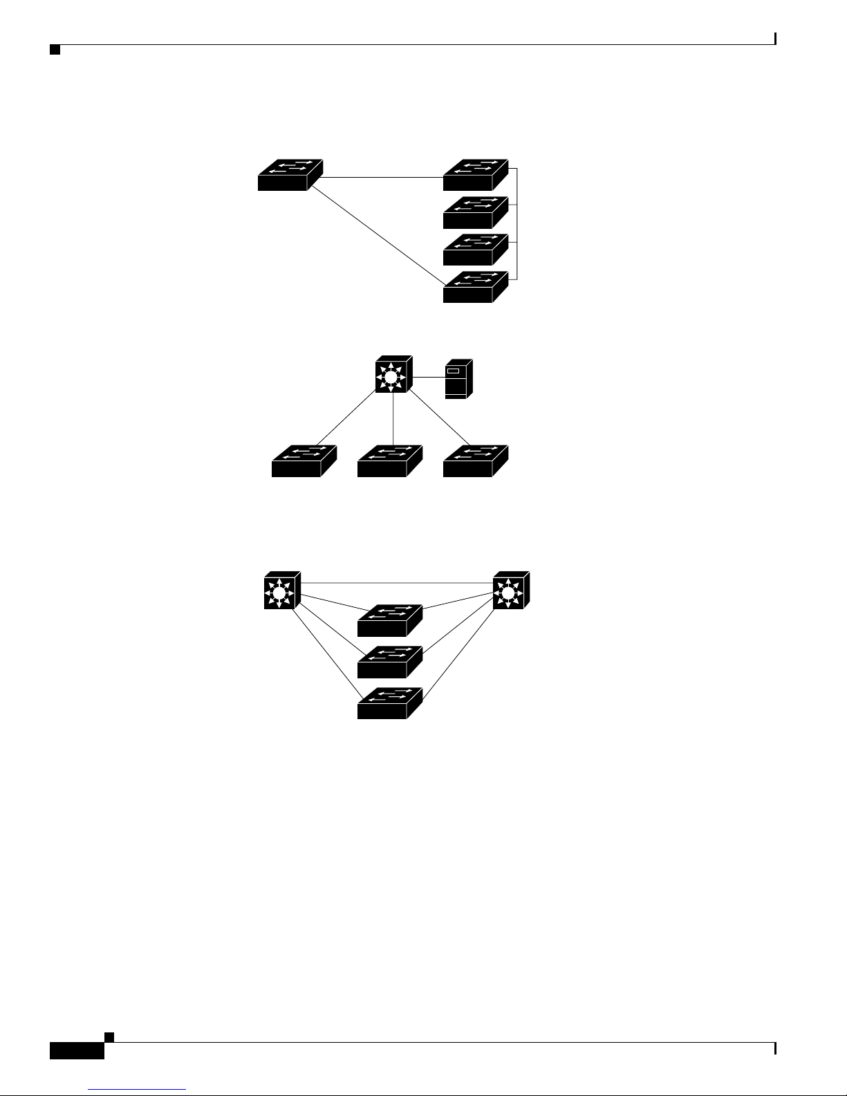
Figure 1-1 shows configuratio n examp les of using the Catalyst switches to create these networks:
• Cost-effective wiring closet—A cost-effective way to connect many users to the wiring closet is to
connect up to nine Catalyst 2900 XL , Catalyst 2950, Catalyst 3500 XL, a nd Catalyst 3550 switches
through Gi gaStac k GBIC connections. When yo u use a stack of Catalyst 2950-48 swi tches, you can
connect up to 432 users. Topreserve switch connectivity if one switch in the stack fails, connect the
bottom switch to the top switch to create a GigaStack loopback, and enable cross-stack UplinkFast
on the cross-stack Gigabit uplinks.
You can crea te backup paths by using Fast Et hern et, Gigabit, or Fast EtherCha nnel , or Gigabit
EtherChannel links. Using Gi gabi t modul es on two of the swi tches, yo u can have redundant up lin k
connections to a Gigabit ba ckbon e switch such as the Catalyst 3550-12G swit ch. If one of t he
redundant conne ction s fail s, the other ca n serve as a backup path. You can configure the stack
members and the Catalyst 3550-12G switch as a switch cluster to manage them through a single IP
address.
• Use QoS to prioritize applications such as IP telephony during
congestion and to help control both delay and jitter within the network.
• Use switches that support a t l ea st t wo qu eu es per port to prioritize voice
and data tr affic as eit her high- or low-prior it y, based on 80 2.1P /Q.
• Use the Catalyst 2900 LRE XL switches to provide up to 15 Mb of IP
connectivity over existing infrastructure (existing telephone lines).
Network Configuration Examples
• High-performanc e workgr oup —For users who require high-speed access to network resources, use
Gigabit modules t o connect the switches directly to a backbone switch in a star configuration . Each
switch in this configurationprovides users with a dedicated 1-Gbps connection to network resources
in the backbone. Co mpare this with the switches in a GigaStack configuration, where the 1-Gbps
connection is sha red among the switches. With th e hig h spe ed uplink to the distri bution se rver, the
user can efficiently o btai n and store dat a f rom servers. Usin g th e following Gigabit modules also
provides flexibility in media and distance options:
–
1000BASE-SX GBIC: fiber co nnec tions of up to 1 804 ft (550 m)
–
1000BASE-LX/LH GBIC: fiber c onne cti ons of up to 32 ,808 ft (10 km )
–
1000BASE-ZX GBIC: fiber connections of up to 32 8,084 ft (100 k m)
–
GigaStack GBIC mo dule for creating a 1-Gbps st ack configuration of u p t o nine supported
switches. The GigaStack GBI C supports one full-duplex li nk (in a point-to-point c onfiguration)
or up to nine half-duplex l inks (in a stack configuration) t o other Gigabit Ethernet devices.
Using the required Cisco proprietary signaling and cabling, the GigaStack GBIC-to-GigaStack
GBIC connec tio n cannot exceed 3 feet (1 meter).
• Redundant Gigabit backbone—Using HSRP, you can create backup paths between
Catalyst 3550-12T-L3 switches. To enhance network reliability and load balancing for different
VLANs and sub nets, you can conn ect the Catalyst 2 950 switches, again in a star c on figuration, to
two backbone switches. If one of the backbone switches fail s, the second backbone switch preser ves
connectivity between the switches and network resources.
78-11380-03
Catalyst 2950Desktop Switch Software Configuration Guide
1-9
Page 34
Network Configuration Ex am ples
Figure 1-1 Example Configurations
Chapter 1 Overview
Catalyst 2950 switch
Cost-Effective
Wiring Closet
High-Performance
Workgroup
Catalyst 3500 XL, and Catalyst 3550 cluster
Catalyst 3550-12T or
Catalyst 3550-12G switch
Si
Catalyst 3550-12T or
Catalyst 3550-12G switch
Si
Catalyst 2900 XL, Catalyst 2950,
Catalyst 3550-12T or
Catalyst 3550-12G switch
1-Gbps HSRP
Catalyst 2900 XL,
Catalyst 2950,
Catalyst 3500 XL,
and Catalyst 3550
GigaStack cluster
Gigabit
server
Si
Redundant Gigabit
Backbone
Catalyst 2900 XL, Catalyst 2950,
Catalyst 3500 XL, and Catalyst 3550 cluster
Small to Medium-Sized Network Configuration
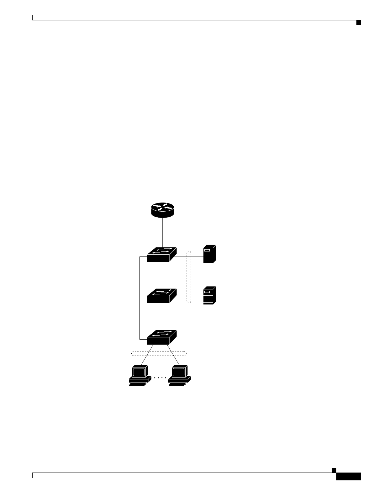
Figure 1-2 shows a configuratio n for a networ k that has up to 25 0 u s ers . Users in this network require
e-mail, file-sharing, database, and Internet access.
Yo u opt imiz e network pe r forma nce by placi ng workst atio ns on the same logical segment as the servers
they access most often. This divides the network in to smaller segments (or workgro ups) and reduces the
amount of tr affic that travels over a network backbone, t here by i ncre asin g t he bandwidth available t o
each user and improving server response time.
Catalyst 2950Desktop Switch Software Configuration Guide
1-10
60992
78-11380-03
Page 35
Chapter 1 Overview
Network Configuration Examples
A network backbone is a h igh- bandw idth connection ( such as Fast Ethern et or Gigabit E the rnet) that
interconnects segments and networkresources.It is require d if numerous segments require access to t he
servers. The Cat alyst 2900, Catalyst 2950, Cata lyst 3500, and C ata lyst 3550 switches in this network are
connected through a GigaStack GBIC on ea ch sw itc h t o form a 1-Gbps network backbo ne. This
GigaStack can also be configured as a switch c luster, wit h primary and secondary command switche s for
redundant cluster management.
Workstations are connected directly to the 10/100 switch ports for their own 10- or 100-Mbps access to
network resources (such as web and m ail servers). Whe n a workstation is configured for full-duplex
operation, it r ece ives up t o 200 Mbps of de dic ated bandwidth fr om the switch.
Servers are connect ed to the G igabit module ports on the switc hes, allowing 1-Gbps throughput to users
when needed. W hen the switch a nd server ports are configured fo r ful l-d uplex op er ation , the links
provide 2 Gbps of bandwidth. For networks that do not req uire Gigabit perf orm ance from a ser ver,
connect the server to a Fast Ethernet or Fast EtherChannel switch port.
Connectinga router to a Fast Ethernet switch port provides multiple, simultaneousaccessto the Internet
through one line.
Figure 1-2 Small to Medium-Sized Network Configuration
Cisco 2600 router
Catalyst 2900 XL,
Catalyst 2950,
Catalyst 3550, and
Catalyst 3500 XL
GigaStack cluster
100 Mbps
(200 Mbps full duplex)
Single workstations
Gigabit
server
1 Gbps
(2 Gbps full duplex)
Gigabit
server
10/100 Mbps
(20/200 Mbps full duplex)
60993
78-11380-03
Catalyst 2950Desktop Switch Software Configuration Guide
1-11
Page 36

Network Configuration Ex am ples
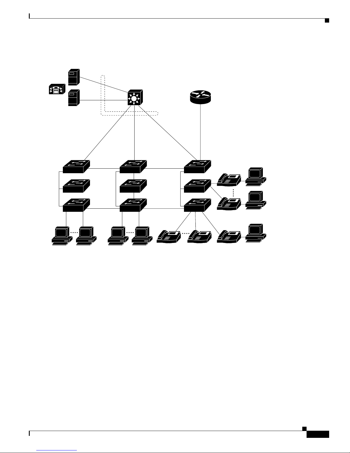
Collapsed Backbone and Switch Cluster Configuration
Figure 1-3 shows a c on figurati on for a network of approxima te ly 50 0 employees. Th is network uses a
collapsed backbon e and switch cluste rs. A collapsed ba ck bone has high-bandw idth uplinks from all
segments and subnetworks to a single device, such as a Gigabit switch, that serves as a single point for
monitoring and controlling the network. You can use a Catalyst 3550-12T-L3 switch, a s sh own, or a
Catalyst 3508G XL switch to cr eate a Gigabit back bone . A Catalyst 3550- 12T-L3 ba ckbo ne sw itch
provides the benefits of inter-VLAN routing and allows the router to focus on WAN access.
The workgroupsare created by clusteringalltheCatalystswitches excepttheCatalyst 4908G-L3 switch.
Using CMS an d Cisc o switch clustering technology, you can group the switches into multiple clusters,
as shown, or into a single cluster. You can manage a cluster through the IP address of its active and
standby command s witche s, regardless of the g eog raphic location of the cluster m embe rs.
This network uses VLANs to segment the network logically into well-defined broadcast groups and for
security management. Data and multimedia traffic are configured on the same VLAN. Voice trafficfrom
the Cisco IP Ph one s are configured on separate VVID s. You can have up to four VVI Ds per wiring
closet. If data, mu lti med ia , and voice tra ffic are assigned to the sa me VLAN, on ly one VLAN can be
configured per wi ring closet. For any switc h port connected to Cisco IP Phones, 802.1P/Q QoS gives
forwarding priority to voice traffic over data traffic.
Groupingserversin a centralized locationprovidesbenefits such as securityandeasiermaintenance. The
Gigabit connections to a server farm provide the workgro ups fu ll acces s to the network re sourc es (s uch
as a call-processing server running Cisco CallManager software, a DHCP server, or an IP/TV multicast
server).
Chapter 1 Overview
Cisco IP Phones are connected—using standard straight-through, twisted-pair cable with RJ-45
connectors—to the 10/100 inline-power ports on the Catalyst 3524-PWR XL switches and to the
10/100 ports on the Catalyst 2950 switches. These multiservice switch ports automatically detect if an
IP phone is conn ect ed. Cisc o Ca ll Manage r c ontr ols c all processing, routing , a nd I P pho ne features and
configuration. Users w ith workstations running Cisco SoftPhone soft ware can place, rece ive, and contro l
calls from thei r P Cs. U sing Cisco IP Phone s, Ci sco C all Man ager software, and Cisco SoftPhone
software integrates telephony and IP networks, and the IP n etwork supports both voice and dat a.
Each 10/100 inline-power port on the Catalyst 3524-PWR XL switches provides –48 VDC power to the
Cisco IP Phone . Th e IP phone can receive redundant power when it al so is connected to an AC power
source. IP phones not connected to the Catalyst 3524-PWR XL sw itches receive power from an AC
power source.
Catalyst 2950Desktop Switch Software Configuration Guide
1-12
78-11380-03
Page 37
Chapter 1 Overview
Figure 1-3 Collapsed Backbone and Switch Cluster Configuration
Gigabit
servers
Cisco
CallManager
Catalyst 3550-12T or
Catalyst 3550-12G switch
Network Configuration Examples
(2 Gbps full duplex)
Catalyst 2950, 2900 XL,
3550, and 3500 XL
GigaStack cluster
Workstations running
Cisco SoftPhone software
1 Gbps
GigaStack cluster
Catalyst
2950,
2900 XL,
3550, and
3500 XL
Si
IP IP IP
Cisco IP Phones
Cisco 2600 router
200 Mbps
Fast EtherChannel
(400-Mbps full-duplex
Fast EtherChannel)
Catalyst
3524-PWR XL
GigaStack cluster
IP
IP
Cisco
IP Phones
60994
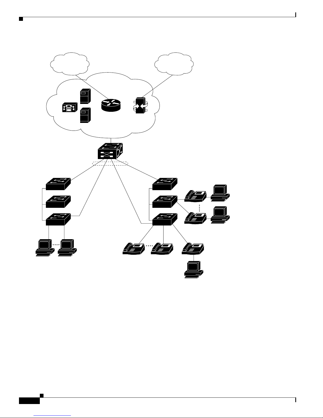
Large Campus Configuration
Figure 1-4 shows a configurat ion for a network of more than 1000 users. Bec ause it can aggregate up to
130 Gigabit connections, a Catalyst 6500 multilayer switch is used as the backbon e switch.
Yo u can use the wo rkgrou p configurations shown in previous examples to create workgrou ps with
Gigabit upli nks to the Cata lyst 6500 swit ch. For example, you can use switch clusters that have a mix of
Catalyst 2950 switches.
The Catalyst 6500 switch p rovides the workgroups with Gigabit a cce ss t o core resource s:
• Cisco 7000 series router for access to the WAN and the Internet.
• Server farm that includes a call-processing server running Cisco CallManager software. Cisco
CallManager cont rols call processing, routing, and IP phone feat ures and configuration.
• Cisco Access gateway(such as Cisco Access Digital TrunkGateway or Cisco Access Analog Trunk
Gateway) that connect s the IP network to the Public Switched Telephone Network ( PSTN) or to
users in an IP telephony netwo rk.
78-11380-03
Catalyst 2950Desktop Switch Software Configuration Guide
1-13
Page 38
Network Configuration Ex am ples
Figure 1-4 Large Campus Configuration
Chapter 1 Overview
WAN
Cisco
CallManager
Catalyst 2950, 2900 XL,
3500 XL, and 3550
GigaStack cluster
Servers
Catalyst
6500 switch
Cisco 7200
or 7500 router
Cisco access
gateway
1 Gbps
(2 Gbps
full duplex)
IP telephony
network or
PSTN
Catalyst
3524-PWR XL
GigaStack cluster
IP
Workstations running
Cisco SoftPhone software
IP
Cisco IP Phones
IP IP IP
Cisco IP Phones
60995
Catalyst 2950Desktop Switch Software Configuration Guide
1-14
78-11380-03
Page 39

CHAPTER
Getting Started with CMS
This chapter provides these topics about t he Cluster Man agem e nt S uite (CMS) soft ware:
• Features, p ag e 2-2
• Front Panel View, p ag e 2-4
• Topology View, page 2-10
• Menus and Toolbar, page 2-15
• Interact ion Modes , page 2 - 2 5
• Wizards, page 2-26
• Online Help, page 2-27
• CMS Window Co mpone nts, pa ge 2-28
• Accessing CMS, page 2- 30
• Ve rif ying Your Changes , page 2-32
• Saving Your Changes, page 2-32
2
• Using Different Versions of CM S, pa ge 2 -33
• Where to Go N ext, page 2-33
Note • For system requirem ents and for browser and Java plug-in co nfigurat ion procedures, re fer to the
release notes.
• For procedures for using CMS, refer to the online help.
Note This chapter describes the CMS interface of the Catalyst 2950 switches. Refer to the appropriate switch
documentation for descriptions of the web- base d management software used on o ther Catalys t switches.
78-11380-03
Catalyst 2950Desktop Switch Software Configuration Guide
2-1
Page 40

Features
Features
Chapter 2 Getting Started with CMS
CMS provides these features ( Figure 2-1) for managing switch clusters and individual swit ches from
Web browsers such as Netscape Communicator or Microsoft Internet Explorer:
• Two views of your network that can be displayed at the same time:
–
The Front Panel view displays the front-panel image of a specific switch or the front-panel
images of all switches in a cluster. From this view, you can select multiple ports or multiple
switches and configure them with the same settings.
When CMS is launched from a command switch, the Front Panel view displays the front-panel
images of all switches in the cluster. When CMS is launched from a noncommand switch, the
Front Panel view displ ays only the fron t panel of the specific switch.
Note CMS from a standalone switch or from a noncommand switch is referred to as Device Manager
(alsoreferredtoasSwitch Manager). Device Man ager is for configuring an individual switc h.
When you select DeviceManagerfora specificswitch in the cluster,youlauncha separateCMS
session. The Device Manager interface can vary between the Catalyst switch platforms.
–
TheTopologyviewdisplays a network mapthatusesiconsthat represent switch clusters,cluster
members, cluster candidates, neighboring devices that are not eligible to join a cluster, and link
types. From this view,youcan select multiple switches and configure them to run with the same
settings. You can also display link information in the form of link reports and link graphs.
This view is available only when CMS i s la unche d from a com mand switch.
• Menus and toolb ar to access configuration and management options:
–
The menu bar provides the complete list of options for managing a single switch and switch
clusters .
–
The toolbar pr ovides button s f or commonly used s witch and cluster configuration options a nd
information w indows suc h as legends and online help.
–
The port popup menu, in the Front Panel view, provides optio ns specific for configuring and
monitoring switch ports.
–
The device popup me nu, in either the Front Panel o r th e Topology v iews, provides switch and
cluster configuration and monitori ng options.
–
The c andida te , member, and link popup menus provide options for configuring and monitoring
devices and links i n the Topology view.
The toolbar a nd popup menus pr ovide q uick ways to ac cess frequently use d menu-bar option s.
• Tools to simplify configurati on tasks:
–
Interactive modes—guide mode and expert mode—that control the presentation o f so me
complex configuration options
–
Wizards that require minimal inf ormati on from you to configure some complex feature s
–
Comprehensive online help that provides h igh-level conc epts and procedure s f or performing
tasks from the window
Catalyst 2950Desktop Switch Software Configuration Guide
2-2
78-11380-03
Page 41
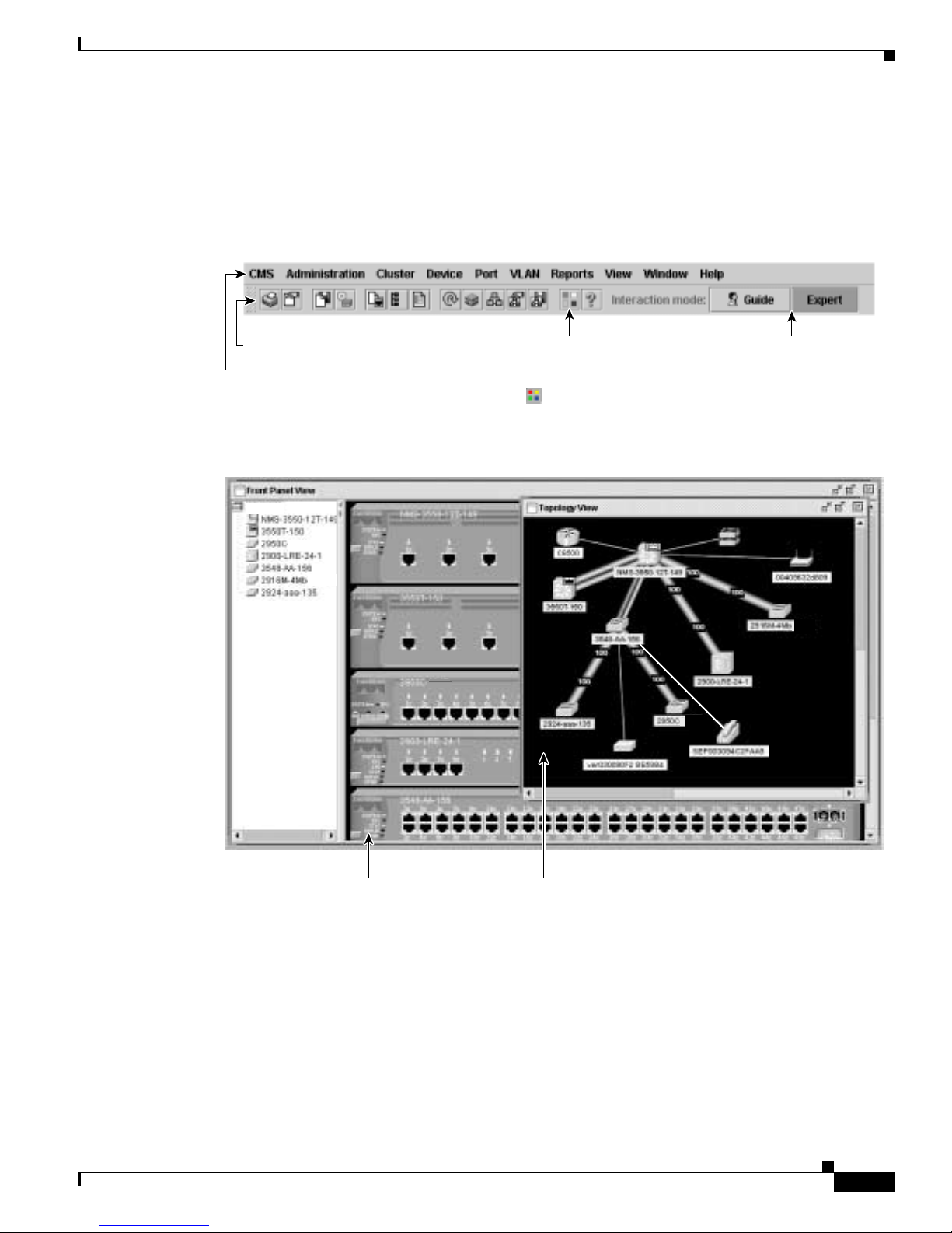
Chapter 2 Getting Started with CMS
• Two levels of access to the configuration options: read-write access for users allowed to change
switch settings; read-only access for users allowed to only view switch settings
• Consistent set of GUI components (such as tabs, buttons, drop-down lists, tables, and so on) for a
consistent approach to setting configuration parameters
Figure 2-1 CMS Features
Features
Toolbar
Menu bar
cluster1
Move the cursor over
the icon to display the
tool tip. For example,
the button displays
the legend of icons
and color codes.
Click Guide or
Expert interaction
mode to change how
some configuration
options will be
presented to you.
65282
Front Panel view of
78-11380-03
the cluster.
Topology view of
the cluster.
Catalyst 2950Desktop Switch Software Configuration Guide
65717
2-3
Page 42

Front Panel View
Front Panel View
When CMS is launched from a command switch, the Front Panel view displays the front-panel images
of all switches i n the cluster (Figur e 2- 2). W he n C MS is launched from a stan dalo ne or non-comm and
member switch, the Front Pane l vi ew displa ys only the fron t panel of the specific switch (Figure 2-3).
Figure 2-2 Front Panel View from a Standalone Switch
Chapter 2 Getting Started with CMS
2950-24
Left-click the Mode
button to change
the meaning of the
port LEDs.
Figure 2-3 Front Panel View from a Command Switch
cluster1
2950-24
LEDs display the
current port mode
and the status of the
switch and
connected RPS.
Right-click a port to
display the port pop-up
menu, and select an
option to view or change
port-related settings.
10.1.1.2
Press Ctrl, and then
left-click ports to select
multiple ports. The color
of the port LED reflects
port or link status.
65719
Cluster tree.
Catalyst 2950Desktop Switch Software Configuration Guide
2-4
Right-click a member
switch image to display
the device pop-up
menu, and select an
option to view or change
system-related settings.
Right-click the
command switch
image to display the
cluster pop-up menu,
and select a cluster-
related option.
78-11380-03
65718
Page 43
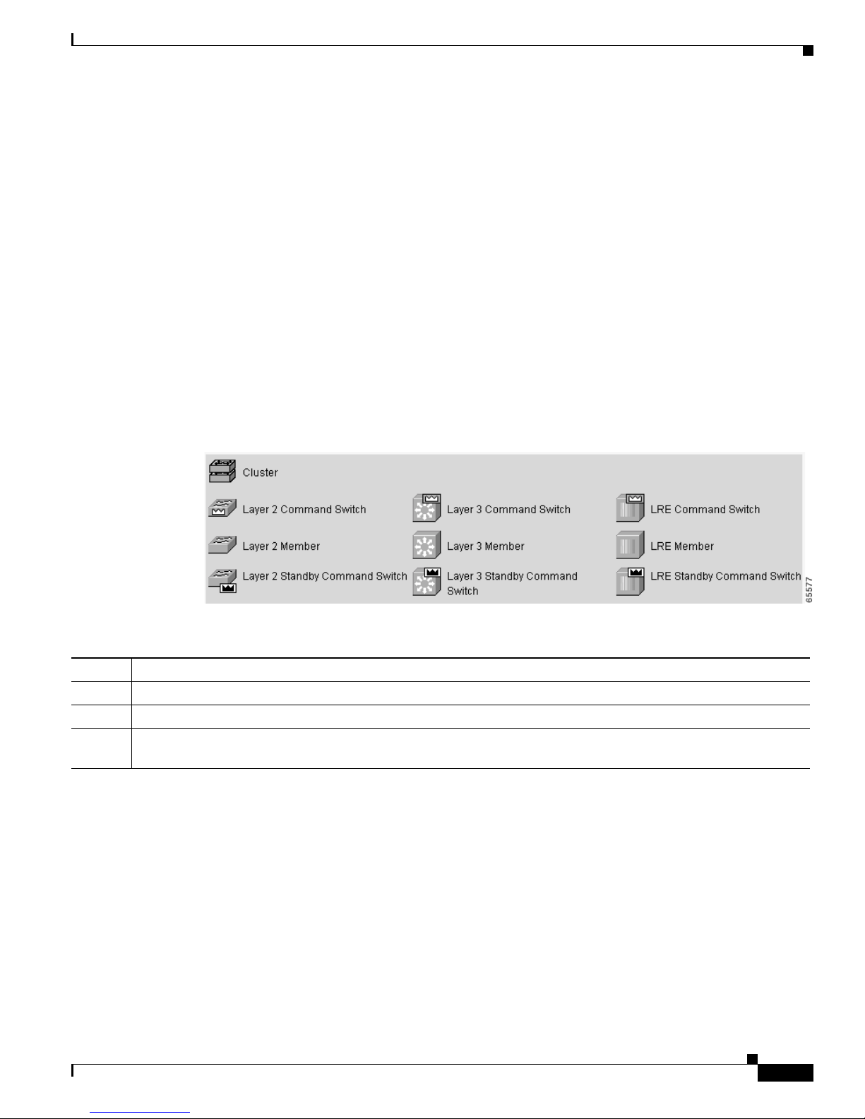
Chapter 2 Getting Started with CMS
Cluster Tree
The c lu st er tree (Figure 2-3) appears in the left frame of the Front Panel view and shows the name of the
cluster a nd a l ist of i ts members. The sequence of the cluster-tree icons (Figure 2-4) mirror th e sequence
of the front-panel images. You can change the sequence by selecting View > Arran ge Front Panel.The
colors of the devices in the cluster tree reflect the status of the devices (Table 2-1).
If you want to configure switch or cluster settings on one or more switches, select the appropriate
front-panel images.
• To s elect a front-pan el image, cli ck either th e cluster-tree ico n or the corres pondi ng front-panel
• To select multiple front-panel images, press the Ctrl key, and left-click the cluster-tree icons or the
If the cluster has many switches, you might need to scroll down the window to d isplay the rest of
front-panel images. Instead of scrolling, you can click an icon in the cluster tree, and CMS then scrolls
and displays t h e co rre spondi ng front-panel i mage .
Figure 2-4 Cluster-Tree Icons
Front Panel View
image. The front-panel image is then highlighted with a yellow outline.
front-panel images. To deselect an icon o r image, press the Ctrl key, and left-click the icon or image.
Table 2-1 Cluster Tree Icon Colors
Color Device Status
Green Switch is operating normally.
Yellow The inte rnal fan of the sw itch is not oper ating , or the switch is receiving power from an RPS.
Red Switch is not powered up, has lost power, or the comma nd switch is unab le to communica te with the me mber
switch.
78-11380-03
Catalyst 2950Desktop Switch Software Configuration Guide
2-5
Page 44

Front Panel View
Front-Panel Images
You can manage the switch f rom a remote station by using the front-panel images. The front-panel
images are updated based on the network polling interval that you set from CMS > Preferences.
Note The Preferences window is not available if your switch access level is r ead-onl y. For more informatio n
about the rea d-o nly access mode, see the “Access Modes in CMS” sectiononpage2-31.
Figure 2-5 shows the port icons as they appear in the front -p anel i mage s. To selec t a port, clic k the port
on the front-panel image. The port is then h ighlighted with a yellow outline. To select multiple ports,
you can:
• Press the left mouse button, drag the pointer over the g roup of por ts that you want to select , and t hen
releasethemousebutton.
• Press the Ctrl key, and click the ports that you want to select.
• Right-click a port, and selec t Select All Ports fro m the port popu p m en u.
Figure 2-5 Port Icons
Chapter 2 Getting Started with CMS
2-6
The following sections provide complete descriptions of the LED images. Similar descriptions of these
LEDs are p rovided in the switch hardware installation guide.
Catalyst 2950Desktop Switch Software Configuration Guide
78-11380-03
Page 45

Chapter 2 Getting Started with CMS
Redundant Power System LED
The Redundant Power Syste m (RPS) LED shows the RPS status (Table 2-2). Certain switc hes in the
switch cluster use a s pecific RPS model:
• Cisco RPS 300 (mo del P WR300- AC-RPS-N1)—Cat alyst 2900 LRE XL, Catalyst 2950,
Catalyst 3524-PWR X L, and Catalyst 3550 switches
• Cisco RPS 600 (mode l PWR6 00-AC-RPS)—Catalyst 2950 switches, except the
Catalyst 2900 LRE X L a nd Catalyst 3524-PWR XL switches
Refer to the appropriate switch hardware documentation for RPS descriptions specific for the switch.
Table 2 -2 R PS LED
Color RPS Status
Black (off) RPS is off or is not installed.
Green RPS is connected and operational.
Blinking gree n RPS is providing p ower to another swi tch in the stac k.
Amber RPS is connected but not functioning.
Front Panel View
The RPS could be in standby mode. To put the RPS in Active mode, press the Standby/Active button on the
RPS, and the L ED should turn gr een. If it does n ot, one of thes e co nditions could exist:
• One of the RPS power supplies could b e down. Contact Cisco Sys tems .
• The RPS fan could have fa iled. Contact Cisco Systems.
Blinking amber Internal power supply of the switch is d own, and redundancy is los t. The switch is operating on the RPS.
78-11380-03
Catalyst 2950Desktop Switch Software Configuration Guide
2-7
Page 46

Front Panel View
Port Modes and LEDs
The port mode s ( Table 2-3) determine the type of inform ation displayed through the port LED s. When
you change por t mo des, the meanings of the port LED colors (Table 2-4)alsochange.
Note The bandwidth utilization mode (UTL LED) does not appear on the front-panel images. Select Reports
> Bandwidth Graphs to display the total bandwidth in u se by the switch. Refer to the switch hardware
installation guide for information about using the UTL LED.
To select or change a mode, click the Mode button until the desired mode LED is green.
Table 2-3 Port Modes
Mode LED Description
STAT Link status of t he p orts. Default mode.
DUPLX Duplex setting on the ports.
SPEED Speed s etting on the ports.
Chapter 2 Getting Started with CMS
Table 2-4 Port LEDs
Port Mode Port LED Color Description
STAT Cyan (off) No link.
Green Link pre s en t.
Amber Link fau l t. Error fram es can affect c onn ec tivity, and erro rs such as excessive
collisions, CRC errors, and ali gn ment and jabber er rors are monitored for a link-fault
indication.
Port is not forwarding. Port was disabled by management, by an address violation,
or was blocked by Spa nnin g Tree Protoc ol ( STP) .
Note After a port is reconfigured, the port LED can remain amber for up to
30 seconds as STP checks the switch f or possible loops.
Brown No link and port is adminis trat ively shut down.
DUPLX Cyan (off) Port is operating i n half-duplex mode.
Green Port is operating in full-duplex mode.
SPEED Cyan (off) Port is operating at 10 Mbps or no link.
Green Port is operating at 100 M bp s (10/100 ports), 155 Mbps (ATM po rts), or 1000 Mbps
(fixed Gigabit port ).
Blinking green P ort is operating a t 10 00 Mbps (10/100/1 000 ports).
Catalyst 2950Desktop Switch Software Configuration Guide
2-8
78-11380-03
Page 47

Chapter 2 Getting Started with CMS
VLAN Membership Modes
Ports in the Front Panel view are outlined by colors (Table 2-5) when you click Highlight VLAN Port
Membership Modes on the Configure VLANs tab on the VLAN window
(VLAN > VLAN > Configure V LANs). The colors show the VLAN membership mode of each port.
The VLAN membership mo de det erm ine s the ki nd of traffic the port carrie s and the number of VLANs
it can belong to. For more inf orma tion ab out t hese m odes, se e the “Assigning VLAN Port M emb ership
Modes” sectiononpage8-4.
Note This feature is not supported on the Cataly st 1900 and Cat alyst 2820 switches.
Table 2-5 VLAN Membership Modes
Mode Color
Static access Light green
Dynamic access Pink
802.1Q trunk Peach
Negotia te trunk White
Front Panel View
78-11380-03
Catalyst 2950Desktop Switch Software Configuration Guide
2-9
Page 48

Topology View
Topology View
The Topology view displ ays how the devices within a switch cluste r are connected and how the switch
cluster is con nect ed to other clu sters and devices. From this view, you c an add and remove cl uster
members. This view provides two levels of de tail of the network topology:
• When you right-c lick a cluster icon and select Ex pand Cluster, the Topology view displa ys the
switch cluster in detail. This view shows the command switch and member switches in a cluster. It
also shows candidate switches that can join the cluster. This view does not display th e details of any
neighboring switch clusters (Figure 2-6).
• When you right-click a command-switch icon and select Collapse Cluster, the cluster is collapsed
and represented by a singl e i co n. The view shows how the cluster is c onne cte d to other cl uster s,
candidate switches, and devices that are not eligible to join the cluster (such as routers, access
points, IP phones, and so on) (Figure 2-7).
Note The Topology view displa ys only the switch cluster and ne twork neighborhoo d of t he specific com mand
or member switch that you access. To display a differentswitch cluster, you need to access the command
switch or member switch of that cluster.
Chapter 2 Getting Started with CMS
Yo u can arrange the device icons in th is view. To move a device icon, click a nd dra g the i con. To se lect
multiple device icons, you can either:
• Press the left mouse button, drag the pointe r over the group of device icons that you wan t to selec t,
andthenreleasethemousebutton.
• Press the Ctrl key, and click the device icons that you want to select.
After selecting the icons, drag the icons to any area in the v iew.
Catalyst 2950Desktop Switch Software Configuration Guide
2-10
78-11380-03
Page 49
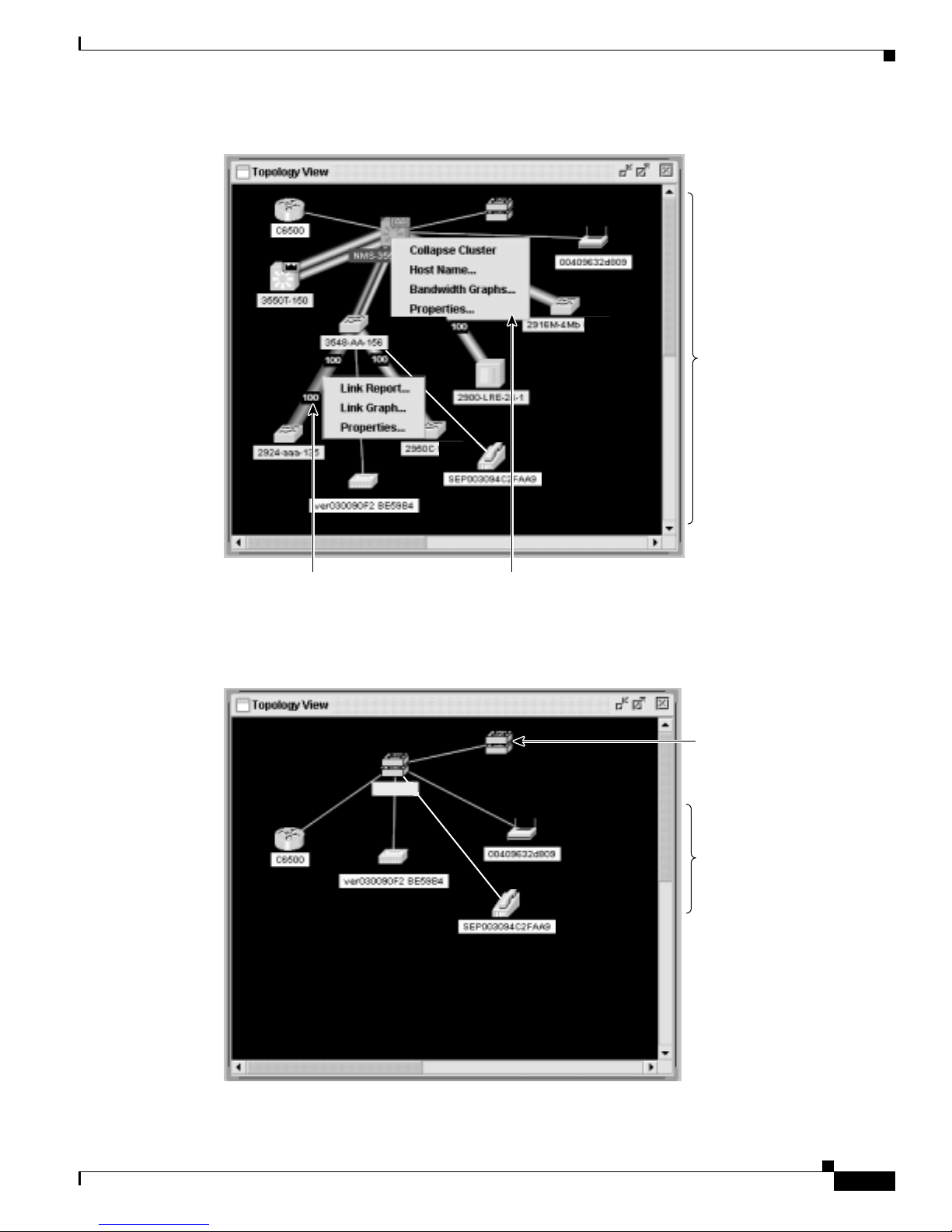
Chapter 2 Getting Started with CMS
Figure 2-6 Expand Cluster View
Topology View
Cluster members of
cluster1 and other
devices connected
to cluster1.
Right-click a
link icon to display
a link popup menu.
Figure 2-7 Collapse Cluster View
cluster1
Right-click a
device icon to display
a device popup menu.
65722
Neighboring cluster
connected to
cluster1.
Devices connected
to cluster1 that are
not eligible to join
the cluster.
78-11380-03
65723
Catalyst 2950Desktop Switch Software Configuration Guide
2-11
Page 50
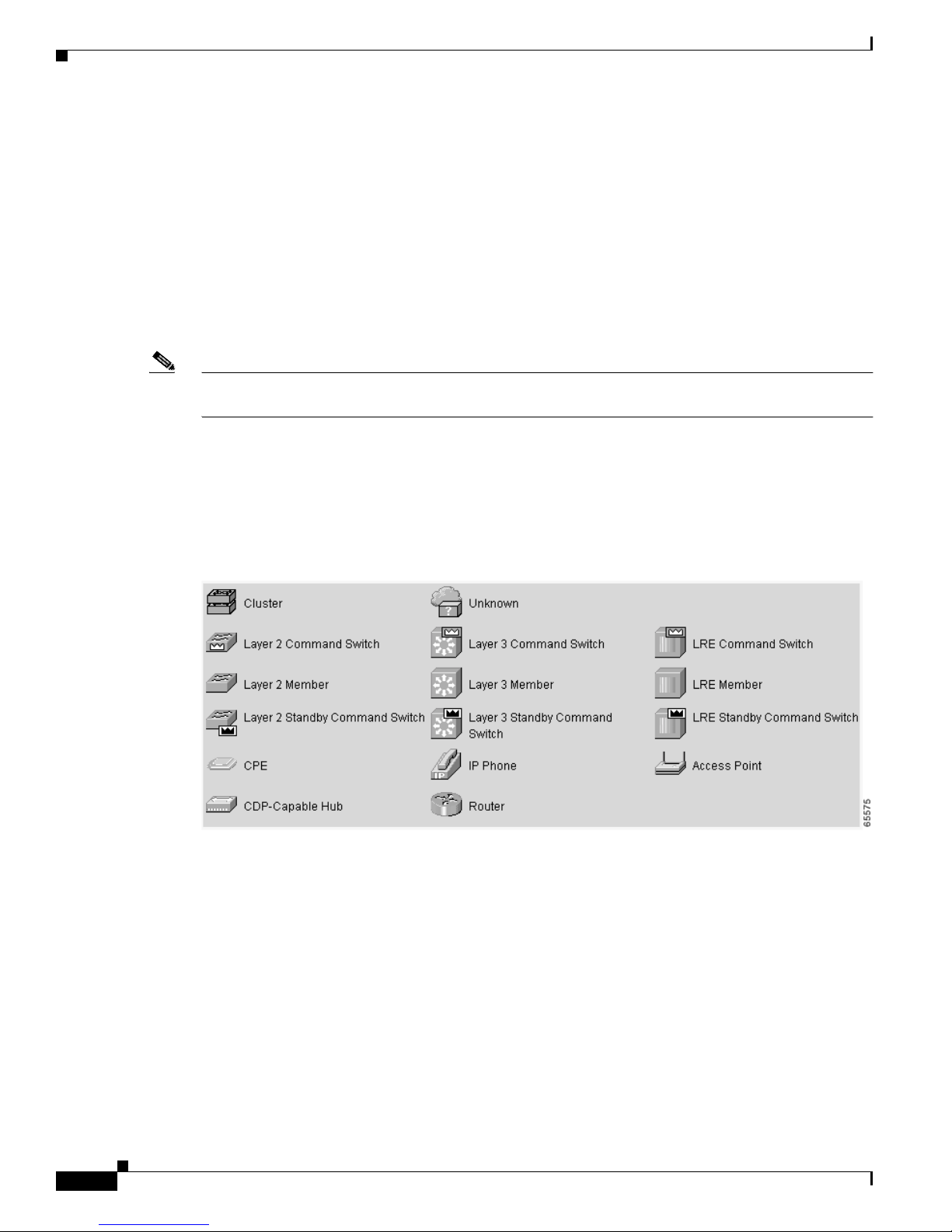
Topology View
Topology Icons
The Topology view and the cluster tree us e the same set of device icons to rep resen t cluster s, comma nd
and standby co mmand switches, and member swit che s ( Figure 2-8). The Topology view also uses
additional icons to represen t t hese types of ne ighb oring devices:
Note Candidate switches are distinguished by the color of their devicelabel.Devicelabelsandtheir colors are
described in the “Colors in the Topology View” sectiononpage2-14.
To select a device, click the icon. The icon is then highlighted. Toselect multiple devices,you can either:
Chapter 2 Getting Started with CMS
• Customer premises equipment (CPE) devices that are connected to Long-Reach Ethernet (LRE)
switches
• Devices that are not eligible to join the cluster, such as Cisco IP phones, Cisco access points, and
Cisco Discovery Protocol (CD P) -capable hubs and rou ters
• Devices that are identified as unknown devices, such as some Cisco devices and third-party devices
• Press the left mouse button, drag th e pointer over th e group of icons that you want to select, and then
releasethemousebutton.
• Press the Ctrl key, and click the icons that you want to select.
Figure 2-8 Topology-View Device Icons
The Topology view also uses a set of link icon s ( Figure 2- 9) to show the link type a nd status bet we en
two devices.To select a link, click the link that you want to select. To select multiple links, press the Ctrl
key, and click the links that you want to select.
Catalyst 2950Desktop Switch Software Configuration Guide
2-12
78-11380-03
Page 51
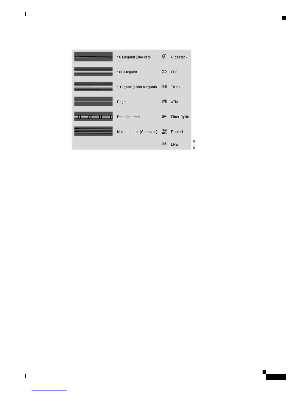
Chapter 2 Getting Started with CMS
Figure 2-9 Topology-View Link Icons
Topology View
Device and Link Labels
The Topology view display s d evice and link informat ion by using these l abels:
• Cluster and switch names
• Switch MAC and IP addresses
• Link type between the devices
• Link speed and IDs of the interfaces on both ends of the link
When using these labels, keep these considerations in mind:
• The IP address displays only in the labels for the command switch and member switches.
• The label of a neighboring cluster icon only displays the IP addre ss of the command-sw itch IP
address.
• The displayed link speeds ar e the actual lin k sp eeds except on the LRE links, w hic h d isplay the
administratively assigned speed settings.
Yo u can change the label set tings from the Topology Options wi ndow, w hich is displayed by selecting
View > Topology Options.
78-11380-03
Catalyst 2950Desktop Switch Software Configuration Guide
2-13
Page 52

Topology View
Colors in the Topolo gy Vie w
The colors of the Topology vi ew icons reflect th e s tatus of the devices a nd links (Table 2-6, Table 2-7,
and Table 2-8).
Table 2-6 Device Icon Colors
Icon Color Color Meaning
Green The device is operating.
1
Yellow
1
Red
1. Available only on the cluster members.
Table 2-7 Single Link Icon Colors
Link Color Color Meaning
Green Active link
Red Down or blocked link
The internal fan of the switch is not ope rating, or the switch is receiving power from an
RPS.
Thedeviceisnotoperating.
Chapter 2 Getting Started with CMS
Table 2-8 Multiple Link Icon Colors
Link Color Color Meaning
Both green All links are active.
One green; one red One link is active, and at least one link is down or blocked.
Both red All links are down or blocked.
The color of a device label shows the clust er membership of the device (Table 2-9).
Table 2-9 Device Label Colors
Label
Color Color Meaning
Green A cluster member, either a member switch or the command switch
Cyan A candidate switch that is eligible to join the cluster
Yellow An unknown device or a device that is not eligible to join the cluster
Topology Display Options
Yo u can set the type of info rmati on displayed in the Topology view by changi ng the settings in the
Topology Op tions window. To di splay this window, select View > Topology Options .Fromthis
window, you can select:
• Device icons to be displayed in the Topology view
• Labels to be displayed with the device and link icons
Catalyst 2950Desktop Switch Software Configuration Guide
2-14
78-11380-03
Page 53

Chapter 2 Getting Started with CMS
Menus and Toolbar
The configuration and monitoring options for configuring switches and switch c lusters are available
from the men u b ar, toolba r, and th e Front-Panel and Topology view popup menus.
Menu Bar
The menu bar provides the complete list o f options for managing a single switch and switch cluster. The
menu bar is t he same whether or not the Front-Panel or Topology views are displayed.
Options displaye d f rom the menu ba r can vary:
• The option f or enabling a command switch is only available from a CMS se ssion launched f rom a
command-capable switch.
• Cluster m anag em ent tasks, such as upgrading the so ftware of groups of switches, are available only
from a CMS se ssion launched from a command switch.
• If you launch CM S from a specific swi tch, the me nu bar dis plays the f eat ures supported only by that
switch.
• If you launch CMS from a command swit ch, the menu b ar di sp lays the features supported on the
switches in the cluster, with these exceptions:
Menus and Toolbar
–
If the command switch is a Layer 3 sw itch , such as a Ca talyst 3550 switc h, the menu bar
displays the features of all Layer 3 and Layer 2 switches in the cluster.
–
If the comm and switch is a Layer 2 switch, suc h as a Catal yst 2950 or Ca tal yst 3500 XL sw itch,
the menu bar displays the features of all Layer 2 switches in the cluster. The menu bar does not
display Layer 3 f eatures even if the cluster has Catalyst 3 550 Layer 3 member switches.
Note We strongl y rec ommend that the hi ghest-e nd, c omma nd-c apable switch in the cluster be the command
switch so that all of the features suppor ted in the cl uster are di splaye d from the menu bar. If you have a
switch cluster with a Cata lyst 3550, that s witc h s hould be the co mm and switch. If your switch c lust er
has Catalyst 29 00 XL, Catalyst 2950, and Cat aly st 3500 XL switc hes, the Catalyst 2950 should be the
command switch. Refer to the release notes for the Catalyst switches that can be part of a switch cluster.
Note • Unless noted otherwise, Table 2-10 lists the menu-bar options available from a Catalyst 2950
command switch and when the cluster contains only Catalyst 2950 member switches. The menu bar
of the command switch displays all menu-bar options available from the cluster, including options
from member switches from other cluster-capable switch platforms.
• The menu-bar options on a Catalyst 2 950 switch chan ge d ep en ding on whether the switch is running
the enhanced software image or not. The footno tes for Table 2-10 list the options available if the
switch is runnin g t he enhanced soft ware image.
• The footnotes in the table describe the availabilityof an option based on your access mode in CMS:
read-only (access level 1–14) and read-write (access level 15). For more information about CMS
access modes, see the “Access Modes in CMS” sectiononpage2-31.
78-11380-03
Catalyst 2950Desktop Switch Software Configuration Guide
2-15
Page 54

Menus and Toolbar
Table 2-10 Menu Bar
Chapter 2 Getting Started with CMS
• If your cluster has these member switches running earlier software releases and if you have
read-only access to these member s witc hes, some c on figuration windows f or those switches display
incomplete information:
–
Catalyst 2950 mem ber switches runni ng Ci sco I OS Release 12.0(5)WC2 or earlier
–
Catalyst 2950 mem ber switches runni ng Ci sco I OS Release 12.0(5)WC2 or earlier
–
Catalyst 3550 mem ber switches run ning Cisco IOS Releas e 12 .1(6) EA1 or earlier
For more information about this limitation, refer to the Cataly st 29 50 release notes.
• These switches do not support CMS access mo des:
–
Catalyst 1900 and Catalyst 2820
–
Catalyst 2900 XL switches with 4-MB CPU DRAM
If these switches are in a cluster that is using CMS access levels, these switches appear as
unavailable devices and canno t be configured fr om CMS.
Menu-Bar Options Task
CMS
Page Setup Set default doc um ent printer prop ertie s t o be used when printing fro m CMS.
Print Preview View the way the CM S w indow or help file will appear when printed.
Print Print a CMS window or help file.
Guide Mode/E xpert Mode
Preferences
2
1
Select which interaction mode to use when you select a configuration option.
Set CMS display properties, such as polling intervals, the default views to open at
startup, and the color of administratively shutdown ports.
Administration
IP Addresses
SNMP
2
2
Configure IP informa tion for a switch.
Enable and disable Simple Network Management Protocol (SNMP), enter community
strings, and co nfigure end stations as trap managers.
System Time
HTTP Po rt
Console Baud Rate
MAC Addr esses
2
2
2
2
Configure the system t ime or configure the Network Time Pr otocol (NTP).
Configure the Hypertext Transfer Protocol (H TTP) port.
Change the baud rate for the switch console port.
Enter dynamic, secure, and static addresses in a switch address table. You can also define
the forwarding behavior of static addresses.
2
ARP
Display the device Address Res olut ion Protocol (ARP) table, and configure the ARP
cache timeout setting.
Save Configuration
Software Up g ra de
System Reload
1
1
1
Save the configuration for the cluster or switch to Flash memory.
Upgrade the so ft ware for the clu ster or a switc h.
Reboot the switch with the latest installed software.
Catalyst 2950Desktop Switch Software Configuration Guide
2-16
78-11380-03
Page 55

Chapter 2 Getting Started with CMS
Table 2-10 Menu Bar (continued)
Menu-Bar Options Task
Cluster
14
15
15
3
Launch a CMS session from the command switch.
Designate a command switch, and name a cluster.
Deleteacluster.
Add a candidate to a cluster.
15
Remove a member from the cluster.
25
Create a Hot Standby Router Protoco l (HSRP) standby group to provide
Cluster Manager
Create Cluster
Delete Cluster
Add to Cluster
Remove fro m Cluster
Standby Command Swi tches
command-switch re dunda ncy.
Hop Count
25
Enter the num ber of hops away tha t a command sw itch looks for me mber s and for
candidate switches.
Device
Device Manager
Host Name
2
STP
IGMP Snooping
5
1
Launch Device Ma nage r for a specific switch.
Change the host name of a switch.
Display and configure STP parameters for a switch.
2
Enable and di sable Internet Group Management Protocol (IGMP) snooping and IGMP
Immediate-Leaveprocessingonthe switch. Join or leavemulticast groups, and configure
multicast routers.
ACL
26
Create and maintain access c ontrol lists (ACLs), and attach ACLs to specific ports.
(guide mode available1)
Security Wizard
2
QoS
(guide mode available on some
options
802.1X
1
)
1
16
Filter certain traffic, such as HTTP traffic, to certain users or devices.
Display submenu options to enable and disable quality of service (QoS) and to configure
or modify th es e parameters :
• Trust settings
• Queues
• Maps
• Classes
• Policies
Configure 802.1X authentication o f devices as they are attached to L AN ports in a
point-to-point infrastructure.
AVVID Wizards
1
• Video Wizard
• Priority Data Wizard
26
2
26
26
(guide mode available1)
26
(guide mode available1)
1
—Optimize multiple video servers for transmitting video traffic.
1
—Provide a higher priority to specific applications.
Menus and Toolbar
6
6
78-11380-03
Catalyst 2950Desktop Switch Software Configuration Guide
2-17
Page 56

Chapter 2 Getting Started with CMS
Menus and Toolbar
Table 2-10 Menu Bar (continued)
Menu-Bar Options Task
Port
Port Settings
Port Search Search for a port through its description.
Port Security
EtherChannels
SPAN
Protected Port
Flooding Control
VLAN
VLAN
(guide mode available1)
Management VLAN
VMPS
Reports
Inventory Display th e device type, software version, IP address, and other information a bout a
Port Statistics Display port statistics.
Bandwidth Graphs Display graphs that plot the t otal bandwidth in use by the switch.
Link Graphs Display a graph showing the bandwidth being used for the selected link.
Link Reports Display the link r epor t for two connected devices. If o ne device is an u nkn own device o r
Resource Monitor Display masks f or ACL an d Qo S po licy maps.
System Messages Display the most recent system messages (IOS messages and switch-specific messages)
2
1
2
2
2
Display and configure port parameters on a switch.
Enable port security on a port.
Group ports int o logical units for high-speed links between sw itc hes .
Enable Switch Port Analyzer (SPAN) port monitoring.
Configure a port to prevent it from re ceiving br idged traffic f rom another port on the
same switch.
2
Block the norm al flooding of unicast and multicast packets, and enable the switch t o
block packet storms.
2
Display VLAN membership, assign ports to VLA Ns, and configure 802 .1 Q t runks.
Display and configu re the VLAN Trunking Proto col (VTP) for inte rswi tch VLAN
membership.
2
2
Change the manageme nt VLAN on the switch .
Configure the VLAN M emb er ship Policy Server (VMPS).
switch.
a candidate, o nly the cluster-member si de of the link d isplay s.
6
sent by the switch software.
This option is availableon the Catalyst 2950 or Catalyst 3 550 switches. It is not available
from the Cata lyst 2 950 switches. You can display the system me ssage s o f th e
Catalyst 2950 switches when they are in a cluster where the command switch is a
Catalyst 2950 switch running Cisco IOS Release 12.1(6)EA2 or later. For more
information about sy stem me ssages, see Appendix B, “System Message s.”
Catalyst 2950Desktop Switch Software Configuration Guide
2-18
78-11380-03
Page 57

Chapter 2 Getting Started with CMS
Menus and Toolbar
Table 2-10 Menu Bar (continued)
Menu-Bar Options Task
View
Refresh Update the views with the latest status.
Front Panel Di spl a y t h e Front Panel view.
Arrange Front Panel
Topology
5
Topology Op tions
Automatic Topology Layout
Save Topology Layout
Window
Help
Overview Obtain an overview of the CMS interface.
What’s New Obtain a description o f the new CMS features.
Help For Active Window Display the help for the active open window. This is the same as clicking He lp from the
Contents List all of the available online help topics.
Legend Display the legend that describes t he icons, labels, a nd links.
About Display the CM S version number.
1. Not available in read-only mode. For more information about the read-only and read-write access modes, see the “Access Modes in CMS” section on
page 2-31.
2. Some options from this menu option are not available in read-only mode.
3. Available only from a Device Manager session on a cluster member.
4. Available only from a Device Manager session on a command-capable switch that is not a cluster member.
5. Available only from a cluster management session.
6. Available only from a switch running the enhanced software image.
15
Rearrange the order in which switches appear in the Front Panel view.
Display the Topology view.
5
15
Select the informa tion to be displaye d in the Topology view.
5
Request CMS t o rearrange the topology layo ut.
Save the presentati on of the cl uster icons tha t you arrange d i n the Topology view to Flash
memory.
List the open w indows in your CMS sessi on.
active w indow.
78-11380-03
Catalyst 2950Desktop Switch Software Configuration Guide
2-19
Page 58

Chapter 2 Getting Started with CMS
Menus and Toolbar
Toolbar
The toolbar buttons display commonl y used switch and cluster configuration options and information
windows such as legendsand online help.Hover the cursorover an icontodisplay the feature.Table 2-11
describes the to olba r options, from left to right on the toolbar.
Table 2-11 Toolbar Buttons
Keyboard
Toolbar Option
Print Ctrl-P Print a CMS window or help file.
Preferences
Save Configuration
Software Up g rad e
Port Settings
VLAN
1
2
2
1
1
Inventory – Display th e device type, the soft ware version, the IP add ress, and other
Refresh – Update the views with the latest status.
Front Panel – Display the Front Panel view.
Topology
Topology O ptions
3
3
Save Topology Lay out
Legend – Display the legend that describes the icons, labels, and links.
Help For Active Window F1 key Display the help f or the active open window. This is the same as clicking Help
1. Some options from this menu option are not available in read-only mode.
2. Not available in read-only mode. For more information about the read-only and read-write access modes, see the “Access Modes in CMS” section
on page 2-31.
3. Available only from a cluster-management session.
Shortcut Task
Ctrl-R Set CMS display properties, such as polling intervals, the views to open at CMS
startup, and the color of administratively shutdown ports.
Ctrl-S Save the configuration for the cluster or switch to Flash memory.
Ctrl-U Upg rade the software for the clust er o r a switch.
– Display and configure port parameters on a switch.
– Display VL AN membership, assign ports to VL ANs, and configure 802.1 Q
trunks.
information about a switch.
– Display the Topology view.
– Select the information to b e displayed in the Topology view.
23
– Save the presenta tion of the clu ster icons that you arranged in the Topology
view to Flash memory.
from the active window.
Catalyst 2950Desktop Switch Software Configuration Guide
2-20
78-11380-03
Page 59

Chapter 2 Getting Started with CMS
Menus and Toolbar
Front Panel View Popup Menus
These popup menus are available in the Front Panel v iew.
Device Popup Menu
You can display all switch and cluster configuration windows from the menu bar, or you can display
commonly used configuratio n windows from the device popup menu (Table 2-12). Todisplay the device
popup menu, cli ck t he switch icon from the cluster tree or the f ron t-pane l ima ge itself, and ri ght- click.
Table 2-12 Device Popup Menu
Popup Menu Option Task
Device Manager
Delete Cluster
Remove from Cluster
Bandwidth Graphs Display graphs that plot the total bandwidth in use.
Host Name
Properties Display information about the device and port on either end of the link and the state o f the link.
1. Available from a cluster member switch but not from the command switch.
2. Available only from the command switch.
3. Available only from a cluster-management session.
4. Not available in read-only mode. For more information about the read-only and read-write access modes, see the “Access Modes in CMS” section on
page 2-31.
1
234
34
4
Launch Device Manager fo r the switch.
Delete a cluster.
Remove a member from the cluster.
Change the na me of the switch.
Port Popup Menu
You can display all port configuration windows from the Port menu on t he menu bar, or you ca n display
commonly used por t configuration windows f rom the port popup me nu (Table 2-13). Todisplaytheport
popup menu, cl ick a specific port image, and ri ght- click.
Table 2-13 Port Popup Menu
Popup Menu Option Task
Port Settings
VLAN
Port Security
Link Graphs
Select All Ports Select all ports on the switch for global configuration.
1. Some options from this menu option are not available in read-only mode.
2. Available on switches that support the Port Security feature.
3. Available only when there is an active link on the port (that is, the port LED is green when in port status mode).
1
1
Display and configure port settings.
Definethe VLAN mode for a portorportsand add ports to VLANs.Notavailableforthe Catalyst 1900
and Catalyst 2820 switches.
12
3
Enable p ort security on a port.
Display a graph showing the bandwidth used by the selected link.
78-11380-03
Catalyst 2950Desktop Switch Software Configuration Guide
2-21
Page 60

Chapter 2 Getting Started with CMS
Menus and Toolbar
Topology View Popup Menus
These popup menus are available in the Topology view.
Link Popup Menu
Yo u can display rep orts and graphs for a specific l ink displayed in the Topology view (Table 2-14). To
display the link popup menu, c lick the link ic on, and right-click.
Table 2-14 Link Popup Menu
Popup Menu Option Task
Link Report Display the link report for two connected devices. If one device is an un known device or a candidate,
only the cluster member side of the link displays.
Link Graph D ispla y a graph showing the bandwidth used by the selected link.
Properties Display information about the device and port on either end of the link and the state of the link.
The Link Report and Link Graph options are n ot available if at b oth ends of the link are
• Candidate switches
• Catalyst 1900 and Ca taly st 28 20 sw itches
• Devices that are not eligible to join the cluster
If multiple links are configured between two devices, when you click the link icon and right-click, the
Multilink Content window appears (Figure 2-10). Click the link icon in this window, and right-click to
display the link popup menu specific for that link.
Figure 2-10 Multilink Decomposer Window
Catalyst 2950Desktop Switch Software Configuration Guide
2-22
78-11380-03
Page 61

Chapter 2 Getting Started with CMS
Device Popup Menus
Specific devices in the Topology v iew displ ay a specific popup m enu:
• Cluster (Table 2-15)
• Commandswitch(Table 2-16)
• Member or standby command switch (Table 2-17)
• Candidate switch with an IP address (Table 2-18)
• Candidate switch without an I P a ddress (Table 2-19)
• Neighboring devices (Table 2-20)
Note The Device Manag er option in these popup m enu s is available in read-o nl y mode on Cat alyst 2950
switches running Ci sco IOS Release 12.0 (5)WC2 and later.It is also available on Catalyst 2950 switches
running Cisco IO S R elease 12.1(6)EA2 a nd later. It is n ot available on the Catalyst 1900 and
Catalyst 2820 switches.
To display a device popup menu, click an icon, and right-click.
Menus and Toolbar
Table 2-15 Device Popup Menu of a Cluster Icon
Popup Menu Option Task
Expand cluster View a cluster-specific topology view.
Properties Display information about the device and port on either end of the link and the state of the link.
Table 2-16 Device Popup Menu of a Command-Switch Icon
Popup Menu Option Task
Collapse cluster View the neighborhood outsi de a specific cluster.
Host Name
1
Change the host name of a switch.
Bandwidth Gr aphs Display gr aphs that plot the total ba ndwidt h in use by the switch.
Properties Display inf orm ation about the d evice and port on ei ther end of th e l ink and the state of the link .
1. Not available in read-only mode. For more information about the read-only and read-write access modes, see the “Access Modes in CMS” section on
page 2-31.
78-11380-03
Catalyst 2950Desktop Switch Software Configuration Guide
2-23
Page 62

Chapter 2 Getting Started with CMS
Menus and Toolbar
Table 2-17 Device Popup Menu of a Member or Standby Command-Switch Icon
Popup Menu Option Task
Remove from Cluster
Host Name
1
Device Manager
Bandwidth Gr aphs Display graphs th at plot the to tal bandwidth in use by the sw itch.
Properties Display information about the device and port on either end of the link and the state of the link.
1. Available only from a cluster-management session.
2. Available from a cluster member switch but not from the command switch.
Table 2-18 Device Popup Menu of a Candidate-Switch Icon (When the Candidate Switch Has an IP Address)
Popup Menu Option Task
Add to Cluster
Device Manager
Properties Displ ay information a bout the device and port on either end of the link and the state of the link.
1. Not available in read-only mode. For more information about the read-only and read-write access modes, see the “Access Modes in CMS” section on
page 2-31.
2. Available from a cluster member switch but not from the command switch.
1
Remove a member from the cluster.
Change the host name of a switc h.
2
1
2
Launch Device Manager for a switch.
Add a cand id at e to a clus ter.
Launch Device Ma nage r f or a switch.
Table 2-19 Device Popup Menu of a Candidate-Switch Icon (When the Candidate Switch Does Not Have an IP Address)
Popup Menu Option Task
Add to Cluster
1
Add a cand id at e to a cl ust er.
Properties Display information about the device and port on either end of the link and the state of the link.
1. Not available in read-only mode. For more information about the read-only and read-write access modes, see the “Access Modes in CMS” section on
page 2-31.
Table 2-20 Device Popup Menu of a Neighboring-Device Icon
Popup Menu Option Task
Device Manager
1
Access th e web management interface of the device.
Note This option is available on Cisco acce ss p oints, but not on Cisco IP phones, hubs, routers
and on unknown devices such as some Cisco devices and third-party devices.
Disqualification Code Display the reason why the device could not join the cluster.
Properties Display in formation about the device and port on either end of the link and the state of th e link.
1. Available from a cluster member switch but not from the command switch.
Catalyst 2950Desktop Switch Software Configuration Guide
2-24
78-11380-03
Page 63

Chapter 2 Getting Started with CMS
Interaction Modes
Yo u can change the interactio n m ode of CMS to either guide or expert mode. Guide mode st eps you
through each feature option and provides information about the parameter. Expert mode displays a
configuration window i n w hic h you configure the feature opti ons .
Guide Mode
Note Guide mode is not available if your switch access level is read-only. For more information about the
read-only acce ss mode, see t he “Access Modes in CMS” sectiononpage2-31.
Guide mode is for use rs who want a step-by-step appro ach for comple tin g a specific configuration task.
This mode is not available for al l f eat ures. A menu-bar option that ha s a person icon means that guide
mode is available for that option.
WhenyouclickGuideModea nd then select a menu-bar option that supports gui de mode, CMS displays
a specific parameter of the feature with information about the parameter field. To configure the feature,
you provide the information that CMS requests in each step until you click Fini sh in the last step.
Clicking Cancel at any time c loses and ends the configuration t ask without apply ing a ny cha nges.
Interaction Modes
Expert Mode
If Expert Mode is se lected and you want to use guide mode, you must click Guide Mode before
selecting an option from th e menu bar,tool bar, or popup menu. If you ch ange the interaction mode after
selecting a con figurati on option, the mo de c hange does not t ake e ffect u ntil you select ano ther
configuration opti on.
Expert mode is for users who prefer to display al l t he parameter fields of a feature in a single CMS
window. Information about the p aram eter fields are provided from Help.
78-11380-03
Catalyst 2950Desktop Switch Software Configuration Guide
2-25
Page 64

Wizards
Wizards
Note Wizards are not available if your switch access level is r ead- only. For more inf ormati on about the
Tool Tips
Chapter 2 Getting Started with CMS
read-only acce ss mode, see t he “Access Modes in CMS” sectiononpage2-31.
Wizards simplify some configuration tasks on the switch. Similar to the guide mode, wizards provide a
step-by-step approa ch for completing a specific configuratio n t ask. Unlike guide m od e, a wizard does
not prompt you t o provide information for all of t he f eat ure o pti ons. Instead, it pro mpts you to provide
minimal informa tion and then use s the default set tings of the rem a ining options to set up default
configurations.
Wizards are not available for all features. A menu-bar option that has wizard m eans that sel ect ing that
option launche s t he wizard fo r th at feature.
CMS displays a popup message when you move your mouse over these devices:
• A yellow device icon in the cluster tree or in Topology view—A po pup displays a fault message,
such as that the RPS is faulty or that the switch is unavailable because you are in read-only mode.
• A red device icon in the cluster tree or in Topology view—A popup displ ays a message that the
switch is down.
If you move your m ouse over a table column heading, a popup displays the full head ing.
Catalyst 2950Desktop Switch Software Configuration Guide
2-26
78-11380-03
Page 65

Chapter 2 Getting Started with CMS
Online Help
CMS provides compr eh ensive online help to assist you in understanding an d p er fo rmin g con figurat ion
and monitoring tasks from the CMS wi ndows (Figu re 2-11).
• Feature help, available from the menu bar by selecti ng Help > Contents, provides backgr oun d
• Dialog-specific help, available from Help on the CMS w indows, provide s procedures for
• Index of help topics.
• Glossary of terms used in the online help.
Yo u can send us feedback ab out the inform ation provi ded in the online help. Click Feedback to display
an online form. Afte r completing the form, click Submit t o send your comments t o Cisco. We appreciate
and value your comments.
Figure 2-11 Help Contents and Index
Online Help
information a nd concepts on the f eatures.
performing tasks.
Glossary of terms used in the online
help.
Legend of icons and color codes.
Feature help, such as concepts.
Information about the CMS interface.
78-11380-03
Enter the first
letters of the topic,
and click Find to
search the index.
Catalyst 2950Desktop Switch Software Configuration Guide
Click Back and
Forward to redisplay
previously displayed
pages. Click
Feedback to send us
your comments about
the online help.
65283
2-27
Page 66
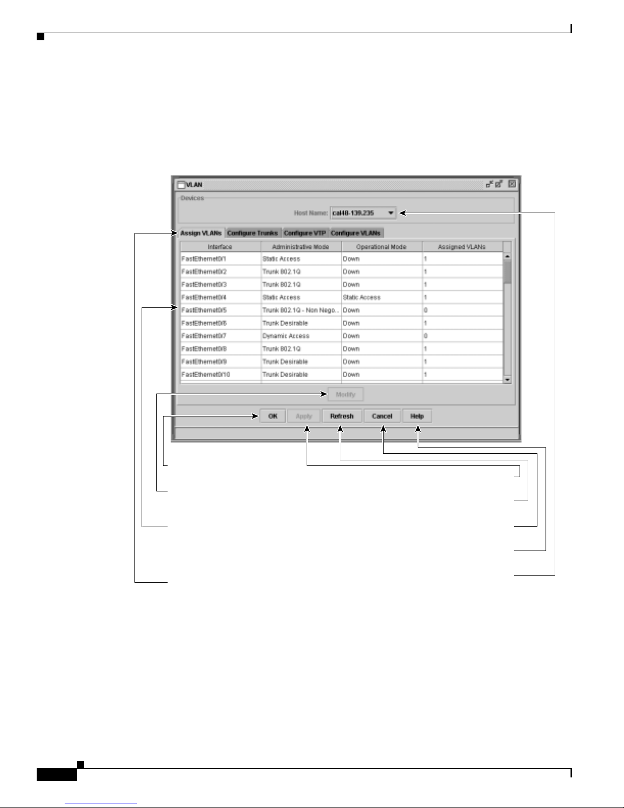
CMS Window Components
CMS Window Components
CMS windows consistently present configuration information. Figure 2- 12 shows the components of a
typical CMS wi ndow.
Figure 2-12 CMS Window Components
Chapter 2 Getting Started with CMS
Host Name List
65580
OK saves your changes and
closes the window.
Modify displays a secondary
window from which you can
change settings.
Click a row to select it. Press Shift,
and left-click another row to select
contiguous multiple rows. Press Ctrl,
and left-click rows to select noncontiguous rows.
Click a tab to display more
information.
Apply saves your changes and leaves
the window open.
Refresh refreshes the window to display
the latest information.
Cancel closes the window without saving
the changes.
Help displays help for the window and the
menu of Help topics.
Select a cluster member from the
Host Name list to display its settings.
To display or change the configuration of a cluster member, you need to select the specific switch from
the Host Name drop-down list. The list appears in the configuration window of each feature and lists
only the cluste r members that sup por t t hat feature. For exam ple, the Host Name list on th e VLAN
window does not inc lud e Catalyst 1900 a nd Catalyst 2820 switches even though they are pa rt o f the
cluster. Similarly, the Host Name list on the LRE Profiles window only lists the LRE switches in the
cluster.
Catalyst 2950Desktop Switch Software Configuration Guide
2-28
78-11380-03
Page 67
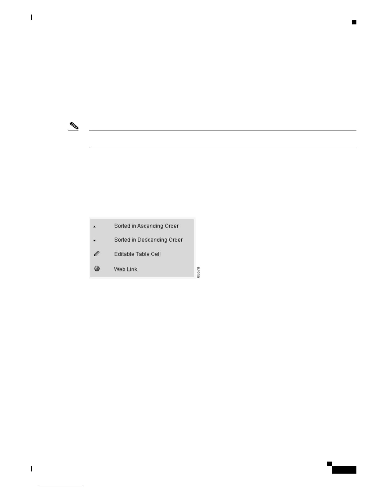
Chapter 2 Getting Started with CMS
Tabs, Lists, and Tables
Some CMS windows have tabs that present different sets of information. Tabs are arranged like folder
headings across the top of the window. Click the tab to display its information.
Listed information can often be changed by selecting an item from a list. To change the information,
select one or more items, and click Modify. Changing multiple items is limited to those items that apply
to at least one of the selections.
Some CMS windows present information in a table format. You can edit the information in these tables.
Note Yo u can resize the width of t he columns to display the co lumn headings, or you can hover your cursor
over t he heading to display a p opup description of the colu mn.
Icons Used in Win dows
Some window have icons for sorting information in tables, for showing which cells in a table are
editable, and for displaying further information from Cisco.com (Figure 2-13).
CMS Window Components
Buttons
Figure 2-13 Window Icons
These are the most common buttons that you u se to change t he i nform ation in a CMS window:
• OK—Save any changes and close the window. If you m ade no changes, the window closes. If CMS
detects errors in your entry, the w ind ow remains open . For more inform ation about error detection ,
see the “Error Checking” sectiononpage2-32.
• Apply—Save any change s made in the window and le ave the window open. If you made no changes,
the Apply button is disabled.
• Refresh—Update the CMS wi ndow with the latest stat us of the device. U nsaved changes are lost.
• Cancel—Do not save any changes ma de i n the window and cl os e t he w indow.
• Help—Display pro cedu re s on performing tasks fro m the window.
• Modify—Display the secondar y wind ow for changing inform ation on the select ed i tem or items.
You usually select an item from a list or table and click Modify.
78-11380-03
Catalyst 2950Desktop Switch Software Configuration Guide
2-29
Page 68

Accessing CMS
Accessing CMS
This section assumes the following:
• You k now the IP address and password of the command switch or a specificswitch.Thisinformation
is either:
–
–
• Yo u know your access privilege level to t he sw itch .
• Yo u have referre d to the release notes fo r system r equi reme nts and have followed the procedures for
installing the r equired Java plug-ins and configuring your browser.
Caution Copiesof the CMS pa ges you display are saved in your browser memory c ache until you exit the browser
session. A pa ssword is not required to redisplay these pages, including the Cisco Systems Access page.
You can access the CLI by clicking Monitor the router - HTML access to the command line interface
from a cached copy of the Cisco Systems Access page. To prevent unauthorized access to CMS and the
CLI, exit your browser to end the browser session.
Chapter 2 Getting Started with CMS
Assigned to the switch by following the setup program, as described in the release notes.
Changedontheswitchbyfollowingtheinformationinthe“Changing IP Information” section
on page 6-1 and “Changi ng the Password” sectiononpage6-10. Considerations f or assigning
IP addr esses and passwords to a command switch and cluster members are described in the “IP
Addresses” sectiononpage5-13and “Pass wor d s ” sectiononpage5-14.
To access CMS, follow these steps:
Step 1 Enter the switch IP address and your privilege level in the browser Location field (Netscape
Communicator) o r Address field (Micr osof t In ter net Explorer). For example:
http://10.1.126.45:184/level/14/
where 10 .1. 126.45 is the switch IP address, 184 is the HTTP port, and level 14 is the privilege level.
Yo u do not need to enter the HTTP por t if the switch is using HTTP port 8 0 ( the default) or e nte r the
privilege l evel if you have read-w rite a cce ss t o the sw itch (privilege level is 15). For information about
the HTTP port, see the “HTTP Access to CMS” section on page 4-3. For in form ati on about privilege
levels, see the “Access Modes in CMS” section on page 2-31.
Step 2 When prompted for a username and password, ente r only the switch enab le password. CMS prompts you
a second time fo r a username and p ass word. Ent er only the enable password again.
If you configure a local userna me a nd password, make sure you enable it by using the ip http
authentication global configuration command. Ent er your username a nd password when p rom pted.
Step 3 Click Web Console.
If you access CMS from a standalone or member switch, Device Manager appe ars. If you acce ss CM S
from a comma nd switch, you can display the Front Panel and Topology views.
Catalyst 2950Desktop Switch Software Configuration Guide
2-30
78-11380-03
Page 69

Chapter 2 Getting Started with CMS
Access Modes in C MS
CMS provides two levels of access to th e configuration options: read-write access and read-only access.
Privilege levels 0 to 15 are supported.
• Privilege level 15 p rovides you with read-write access to CMS.
• Privilege levels 1 to 14 provide you with read-only access to CMS. Any options in the CMS
windows, menu bar, toolba r, and popu p menus that change the switch or cluster configurati on are
not shown in read-only mode.
• Privilege level 0 denies access to CMS.
If you do not include a pr ivilege level when you access CM S, t he s wit ch verifies if you have
privilege-level 1 5. If you do not , you are deni ed access to CM S. If you do have privilege-level 15, you
are granted read-write access. Therefore, you do not need to include the privilege level if it is 15.
Entering zero den ies access to CM S. For more informati on about privilege levels, s ee the “Changing the
Password” section on page 6-10.
Note • If your cluster has these member switches running earlier software releases and if you have
read-only a ccess to these membe r switches, some con figuration windows f or those switches d isplay
incomplete information:
–
Catalyst 2950 membe r sw itches running Cisco I OS Re lease 12.0(5)WC2 or ea rlier
Accessing CMS
–
Catalyst 2950 membe r sw itches running Cisco I OS Re lease 12.0(5)WC2 or ea rlier
–
Catalyst 3550 me mber switches running Cisco IOS Rel ease 12.1(6)EA1 or earlier
For more information about this limitation, refer to the Cataly st 29 50 release notes.
• These switches do not suppo rt r ead- only mode on CMS:
–
Catalyst 1900 and Catalyst 2820
–
Catalyst 2900 XL switches with 4-MB CPU DRAM
In read-only mode, these switches appe a r as unavailable devices and cannot be c on figured from
CMS.
78-11380-03
Catalyst 2950Desktop Switch Software Configuration Guide
2-31
Page 70

Verifying Your Changes
Verifying Your Changes
CMS provides noti fication cues to hel p you track an d c onfirm the changes y ou make.
Change Notification
A green border arou nd a field or table cell means t hat yo u ma de an unsaved ch an ge to t he field or t able
cell. Previous information in that fieldor table cell is displayed in the window status bar.When you save
the changes o r if you cance l the change, the green b ord er disappears.
Error Checking
A red border around a field means that you entered invalid data in the field. An error message also
displays in the window status bar. When you enter valid data in the field, a green border replaces the red
border until y ou either save or ca ncel the change .
If there is an error in communicating with the switch or if you make an error while performing an action,
a popup dialog notifies you about the error.
Chapter 2 Getting Started with CMS
Saving Your Changes
Note The Save Configuration opt ion is not available if your switch a cce ss level i s r ead- only. For more
information a bout the read-onl y access mode, see the “Access Modes in CMS” section on page 2-31.
Tip As you make c luste r configuration chan ges (except for ch ange s t o the Topology view an d in the
Preferences window), make sure that you periodicall y save the configuration from the command switch.
The configuration is saved on the c om mand and member switches.
The front-p an el images and CMS windows always display the running configuration of the switch.
When you make a configuration chang e t o a switch or s witch cluster, the change be come s pa rt of the
running configuratio n. The change do es not automatically become part of the config.txt file in Flash
memory, whic h is the startup c onfiguration used each tim e t he sw itch restarts. If yo u do not save your
changes to Flash memory, they are lost when the switch restarts.
To save all configuration changes to Flash memory, you must select Admin i stration > Save
Configuration.
Note Catalyst 1900 and Catalyst 2820 switches automatically saveconfigurationchangesto Flash memory as
they occur.
Catalyst 2950Desktop Switch Software Configuration Guide
2-32
78-11380-03
Page 71

Chapter 2 Getting Started with CMS
Using Different Versions of CMS
When managing switch clusters through CMS, rem embe r that cluster s can have a mix of switch models
usingdifferent IOS releasesandthatCMSin earlier IOS releasesandondifferent switch platformsmight
look and function d ifferently from CMS in this IOS release.
When you select D evice > Device Manager for a clust er m em ber, a new browser se ssion is launched ,
and the C MS version fo r that swit ch is displ ay ed .
Here are examples of how CMS can differ between IOS releases and switch platforms:
• On Catalyst switches running Cisco IOS Release 12.0(5)WC2 or earlier or Cisco IOS
Release 12.1(6) EA1 or earlier, the C MS versions in th ose s oft ware releases mi ght appear simil ar but
are not the same as t his release. For exam ple , the Topology vi ew in t his release is not the sam e as
the Topology view or Cluste r View in those earlier so ftware releases.
• CMS on the Cat al yst 1 900 and Catalyst 2820 switches is referred t o as Switch Manager.Cluster
management options are not available on these switches. This is the earliest version of CMS.
Refer to the documentation specific to the switch and its IOS release for descriptions of the CMS version
you are using.
Using Different Versions of CMS
Where to Go Next
The rest of this guide provi des information abo ut and CLI proc edur es for the soft ware features suppor ted
in this release. For CMS procedures and window descriptions, refer to the online help.
Refer to the r elea se notes for:
• CMS software requirements
• Procedures for browser configuration
• Procedures for accessing CMS
78-11380-03
Catalyst 2950Desktop Switch Software Configuration Guide
2-33
Page 72

Where to Go Next
Chapter 2 Getting Started with CMS
Catalyst 2950Desktop Switch Software Configuration Guide
2-34
78-11380-03
Page 73

CHAPTER
Using the Command-Line Interface
This chapter describes the IOS co mm and-l ine interface ( CLI ) that you can use to configure your
switches. It contains these sections:
• IOS Command Modes, page 3- 1
• Getting H elp, page 3-3
• Abbreviating Commands , page 3-3
• Using no and default Forms of Commands, pag e 3-4
• Understanding CLI Messages, page 3-4
• Using Command History, page 3-5
• Using Editing Features, page 3-6
• Searching and Filtering Output of show and more Commands, page 3-8
• Accessing the CLI, page 3-9
3
IOS Command Modes
The Cisco IO S use r i nte rface is divided into many different modes. Th e c omman ds available to you
depend on which mode you are currently in. En ter a question mark (?) a t the sy stem pr ompt t o ob tain a
list of commands available for each command mode.
When you start a session on the switch, you b egin in user mode, o ften called user EXE C m ode. Only a
limited subset of the commands are available i n user EXEC mode. For example, most of the user EXEC
commands ar e one-time co mm ands , such as show commands, whi ch show the current configuration
status, and clear commands, which clear counters or interfaces. T he u ser EXEC comma nd s ar e not saved
when the switc h reboo ts.
To have access to all commands, you must enter privileged EXEC mode. Normally, you must enter a
password to enter privileged EXEC mode. From this m ode, you can en ter any privileged EXEC
command or enter glob al configuration m ode .
Using the configur atio n modes (global , i nte rface , and line), you can make cha ng es to the runni ng
configuration. If you save the configurati on, these command s a re stored when the switch r eb oots. To
access the various configuration mode s, you must start at global configu ratio n m ode. From global
configuration mode , you can enter interface configurati on mode and lin e configuration mode.
Table 3-1 describes the main command modes, how to access each one, the prompt y ou see in that mode, and
how to exit the mode. The examples in the table use the host name switch.
78-11380-03
Catalyst 2950Desktop Switch Software Configuration Guide
3-1
Page 74

Chapter 3 Using the Command-Line Interface
IOS Command Modes
Table 3-1 Command Mode Summary
Mode Access Method Prompt Exit Method About This Mode
User EXEC Begin a session with
your switch.
Privileged EXEC While in user EXEC
mode, enter the enable
command.
VLAN configuration While in privileged
EXEC mode, enter the
vlan database
command.
Global configuration While in privileged
EXEC mode, enter the
configure command.
Interface
configuration
While in global
configuration mode,
enter the interface
command (with a
specific interface).
Line configuration While in g lobal
configuration mode,
specify a line with the
line vt y or line console
command.
Switch>
Switch#
Switch(vlan)#
Switch(config)#
Switch(config-if)#
Switch(config-line)#
Enter logout or quit. Use this mode to
• Change terminal
settings.
• Perform basic tests.
• Display system
information.
Enter disable or exit. Use this mode to verify
commands that you have
entered. Us e a password
to protect access to this
mode.
To exit to privileged
EXEC mode, enter
exit.
Use this mode t o
configure
VLAN-specific
parameters.
To exit to privileged
EXEC mode, enter
exit or end,orpress
Use this mode t o
configure parameters that
applyto theentireswitch.
Ctrl-Z.
To exit to global
configuration mode,
enter exit.
Use this mode t o
configure parameters for
the Etherne t i nter fac es.
To return to
privileged EXEC
mode, press Ctrl-Zor
enter end.
To exit to global
configuration mode,
enter exit.
Use this mode t o
configure parameters for
the terminal line.
To return to
privileged EXEC
mode, press Ctrl-Zor
enter end.
Catalyst 2950Desktop Switch Software Configuration Guide
3-2
78-11380-03
Page 75

Chapter 3 Using the Command-Lin e In te rface
Getting Help
Yo u can enter a question mark (?) at the system prompt to display a list o f commands available for each
command mode. You can also obtain a list of associated keywords and arguments for any command, as
shown i n Table 3-2.
Table 3 -2 H elp Summ ary
Command Purpose
help Obtain a brief description of the help system in any command mode.
abbreviated-command-en try? Obtain a list of commands that begin with a particular character string.
For example:
Switch# di?
dir disable disconnect
abbreviated-command-en try<Tab> Complete a partial command name.
For example:
Switch# sh conf<tab>
Switch# show configuration
? List all commands available for a particular command mode.
For example:
Switch> ?
command ? List the associated keywords for a command .
For example:
Switch> show ?
command keyword ? List the asso ciat ed arguments for a keyword.
Getting Help
For example:
Switch(config)# cdp holdtime ?
<10-255> Length of time (in sec) that receiver must keep this packet
Abbreviating Commands
Yo u only have to enter enough chara cters for the swit ch t o recognize the command as unique. This
example shows how to ente r the show configuration command:
Switch# show conf
78-11380-03
Catalyst 2950Desktop Switch Software Configuration Guide
3-3
Page 76

Using no and default Forms of Com m ands
Using no and default Forms of Commands
Almostevery configuration command also has a no fo rm . In gen er al , use t he no form to disabl e a featur e
or function o r reverse the action o f a command. For example, the c om mand no shutdown reverses the
shutdown of an interface. Use the command without the keyword no to re-enable a disabled f eature or
to enable a feature that is disabled by default.
Configuration commands can also have a default form. The default fo rm of a comma nd returns the
command setting to its default. Most commands are disabled by default, so the default form is the same
as the no form.However,somecommands are enabled bydefaultandhave variablessettocertaindefault
values. In these cas es , the default command enables the command and sets variables to their default
values.
Understanding CLI Messages
Table 3-3 list s so me e rror messages that y ou might encounter while using the CLI to configure your
switch.
Chapter 3 Using the Command-Line Interface
Table 3-3 Common CLI Error Messag e s
Error Message Meaning How to Get Help
% Ambiguous command:
"show con"
% Incomplete command.
% Invalid input detected
at ‘^’ marker.
You did not enter enough characters
foryourswitchtorecognizethe
command.
You di d not enter all of the keywords
or values re qu ir ed by this co mma nd .
You entered the command
incorrectly. The caret (^) marks the
point of t he e rro r.
Re-enter the command followed by a question mark (?)
with a space between the command and the question
mark.
The possible keywords t hat you can en ter with the
command are displayed.
Re-enter the command followed by a question mark (?)
with a space between the command and the question
mark.
The possible keywords t hat you can en ter with the
command are displayed.
Enter a question mark (?) to display all of the
commands that are available in this command mode.
The possible keywords t hat you can en ter with the
command are displayed.
Catalyst 2950Desktop Switch Software Configuration Guide
3-4
78-11380-03
Page 77

Chapter 3 Using the Command-Lin e In te rface
Using Command History
The IOS provides a history or record of commands that you have entered. This feature is particularly
useful fo r recalling long or complex commands or e ntrie s, including access lists. You can customize the
command history feature to suit your needs as described in these sections:
• Changing the Com mand History Buffer Si ze, page 3-5
• Recalling Commands, page 3-5
• Disabling the C omma nd History Featur e, page 3-5
Changing the Command History Buffer Size
By default, the switch records ten command lines in its history buffer. Beginning in user EXEC mode,
enter this co mm and to change t he number of co mm and lines that the switch records during the current
terminal session:
Switch> terminal history [size number-of-lines]
The range is from 0 to 2 56.
Using Command History
Beginning in line configuration m ode, enter this command to configure the numb er of command lines
the switch records for all sessions on a particular line:
Switch(config-line)# history [size number-of-lines]
The range is from 0 to 2 56.
Recalling Commands
To recal l c omma nds from the hist ory buffer, perform one of the actions listed in Table 3-4:
Table 3-4 Recalling Commands
1
Action
Press Ctrl-P o r the up arrow key. Recall commands in the history buffer, beginning with the most recent command.
Press Ctrl-N o r the down arrow key. Return to more rece nt commands in the history buffer after recal ling commands
show history While in user EXEC mode, list the last several command s that you just e ntere d.
1. The arrow keys function only on ANSI-compatible terminals such as VT100s.
Result
Repeat the key sequence to re call succe ssively older commands.
with Ctrl-P or the u p arrow key. Repeat the key sequence to recall successively
more recent commands.
Disabling the Command Hist or y Feat ure
The command history feature is automatically enabled.
To disable the feature during the current terminal session, enter the terminal no history use r EXEC
command.
To disable command history for the line, enter the no history line co nfigurat ion command.
78-11380-03
Catalyst 2950Desktop Switch Software Configuration Guide
3-5
Page 78

Using Editing Features
Using Editing Features
This section describes the editing features that can help you manipulate the command line. It contains
these sections:
• Enabling and Disabling Editing Features, page 3-6
• Editing Comman ds through Keystrokes, page 3 -6
• Editing Comman d L ines that Wrap, page 3-7
Enabling and Disabling Editing Features
Although enhan ced editing mode is automat ical ly e na bled, you can disable it.
To re-enable the enhanced editing mode for the current terminal session, enter this command in user
EXEC mode:
Switch> terminal editing
To reconfigure a specific line to have enhanced editing mode, enter this command in line configuration
mode:
Switch(config-line)# editing
Chapter 3 Using the Command-Line Interface
To globa ll y d isabl e enhanced ed iti ng mode, enter this comm and in line c onfigura tio n m od e:
Switch(config-line)# no editing
Editing Commands through Keystrokes
Table 3-5 shows the keystrokes that you need to edit command lines.
Table 3-5 Editing Commands through Keystrokes
Capability Keystroke
Move around the com mand line to
make changes or corrections.
Recall commands from the buffer and
paste them in the command l ine. ( The
switch provides a bufferwith the last
ten items that you deleted.)
Press Ctrl-B,orpressthe
left arrow key.
Press Ctrl-F,orpressthe
right arrow key.
Press Ctrl-A. Move the cu rsor to the beginning of the com mand line.
Press Ctrl-E. Move the cursor to the end of the command line.
Press Esc B. Move the cursor back o ne wor d.
Press Esc F. Move the cu rsor f or ward one word.
Press Ctrl-T. Transpose the character to the left of the c ursor with the
Press Ctrl-Y. Recall the most recent entry in the buffer.
1
Purpose
Move the cursor back one charact er.
Move the cursor forward one character.
character located at the cursor.
Catalyst 2950Desktop Switch Software Configuration Guide
3-6
78-11380-03
Page 79

Chapter 3 Using the Command-Lin e In te rface
Table 3-5 Editing Commands through Keystrokes (continued)
Using Editing Features
Capability Keystroke
Press Esc Y. Reca ll the next buffer entr y.
Delete entries if you make a mistake
or change your mind.
Press the Delete or
Backspace key.
Press Ctrl-D. Delet e the char act er at the cursor.
Press Ctrl-K. Delete all characters from the cursor to the end of the
Press Ctrl-U or Ctrl-X. Delete all c hara cters from the c ursor to the beginning of
Press Ctrl-W. Delete the word to the left o f the cursor.
Press Esc D. Delete fro m th e cursor to t he e nd of the word.
Capitalize or lowercase words or
Press Esc C. Capitalize at the cursor.
capitalize a set of letters.
Press Esc L. Change the word a t t he c ursor to lowercase.
Press Esc U. Capitalize letters from the cursor to the end of the word.
Scroll down a line or s creen on
Press the Return key. Scroll down one line.
displays that are longer than the
terminal screen can display.
1
Purpose
The buffer contains only the last ten items that you have
deleted or c ut. If you p ress Esc Y more than ten times, you
cycle to the first buffer entry.
Erase the character t o the left o f the curs o r.
command line.
the command line.
Note TheMorepromptisusedfor
any output that has more
lines than can be displayed
on the terminal screen,
including show command
output. You can use the
Return and Space bar
keystrokes wh enever you see
theMoreprompt.
Press the Space bar. Scroll down one screen.
Redisplay the current command line
Press Ctrl-L or Ctrl-R. Redisplay the current command line.
if the switch suddenly sends a
message to your scre en.
1. The arrow keys function only on ANSI-compatible terminals such as VT100s.
Editing Command Lines that Wrap
Yo u can use a wra par ound feature for c omma nds that extend beyond a single line on the scre en. When
the cursor reaches the right margin, the command line shifts ten spaces to the left. You cannot see the
first ten charact ers of the line, but you can sc roll back and check the syn tax at the beginn ing of the
command.
78-11380-03
Catalyst 2950Desktop Switch Software Configuration Guide
3-7
Page 80

Searching and Filtering Output of show and more Commands
To scroll back to the beginning of the command entry,press Ctrl-B or the left arrowkeyrepeatedly. You
canalsopressCtrl-A to immediately move to the beginning of the line.
Note The arrow keys function only on ANSI-compatible terminals such as VT100s.
In this example, the access-list co mma nd entry extends beyon d o ne line. When the cursor first rea ches
the end of the line, the line is shifted ten spaces to the left and redisplayed. The dollar sign ($) shows
that the line has been scrolled to the left. Each time the cursor reaches the end of the line, the line is again
shifted ten spaces to the left.
Switch(config)# access-list 101 permit tcp 131.108.2.5 255.255.255.0 131.108.1
Switch(config)# $ 101 permit tcp 131.108.2.5 255.255.255.0 131.108.1.20 255.25
Switch(config)# $ t tcp 131.108.2.5 255.255.255.0 131.108.1.20 255.255.255.0 eq
Switch(config)# $ 108.2.5 255.255.255.0 131.108.1.20 255.255.255.0 eq 45
When you have comple ted the entry, press Ctrl-A to check the complete syntax before pressing the
Return key to execute the command. The d ollar sign ($) appears at the end of the line to s how that t he
line has been scrolled to the right:
Switch(config)# access-list 101 permit tcp 131.108.2.5 255.255.255.0 131.108.1$
Chapter 3 Using the Command-Line Interface
The software assumes y ou have a termin al screen tha t is 80 columns wide. If you have a width other than
that, u se the terminal width user EXEC command to set the width of your terminal.
Use line wrapping with the command history feature to rec all a nd modify previous comp lex co mmand
entries. For information about recalling previous command entries, see the “Editing Commands through
Keystrokes” section o n page 3-6.
Searching and Filtering Output of show and more Commands
You can search and filter the output for show and more commands. This is useful when you need to sort
through large amou nts of output or if you want t o exclude output t hat you do not need to see.
To use t his f unct ional ity, enter a show or more command followed by the pipe character (|), one of the
keywords begin, include,orexclude, a nd an expression th at you want to se ar ch for or filter out :
command |{begin | include | exclude} regular-expression
Expressions are case-sensitive. For example, if you enter | exclude output the lines that contain output
are not displa yed, but the lines t hat contain Output are displayed.
This example sh ows how to include in the output display only lines w here the expression protocol
appears:
Switch# show interface | include protocol
Vlan1 is up, line protocol is up
Vlan10 is up, line protocol is down
GigabitEthernet0/1 is up, line protocol is down
GigabitEthernet0/2 is up, line protocol is up
Catalyst 2950Desktop Switch Software Configuration Guide
3-8
78-11380-03
Page 81

Chapter 3 Using the Command-Lin e In te rface
Accessing the CLI
This procedure assumes you have a lread y a ssign ed IP information and password t o the switch or
command s witch. You can assign this information to the switch in these ways:
• Using the setup program, as described in the release notes
• Manually assigning an IP address and password, as described in the “Changi ng IP Informati on”
sectiononpage6-1and “Changing the Password” sectiononpage6-10.
Considerations for assigning this information to a command switch and cluster members are
described in the “IP Addr esses” section on page 5-13 an d “Passwords” sectiononpage5-14.
To access the CLI, follow these steps:
Step 1 Start the emu lation software (such as ProComm, H yper Terminal, tip, or minicom) on th e management
station.
Step 2 If necessary, reconfigure the terminal-emulation software to match the switch console port settings
(default settings are 9600 baud, no parity, 8 d ata bits, and 1 stop bit).
Step 3 Establish a connection with the switch by either
Accessing the CLI
• Connecting the sw itch console port to a management station or dial-up modem. For information
about connectin g t o the console port, refer to the switch h ar dware installation gu ide.
• Using any Telnet TCP/IP packag e from a remote management station. The swi tch must have
network connectivity wit h th e Telnet c lient , a nd the switch must have an enable sec ret password
configured. For informa tion about configuring the switch for Telnetaccess,see the “SNMP Network
Management Platfo rm s” sectiononpage4-4.
The switch supp orts up to 16 si multa neous Telnet sessions. Changes made by on e Telnet user are
reflected in a ll other Telnet s ession s.
After you connect through the console port or through a Telnet session, the User EX EC promp t appear s
on the man ag em en t station.
Accessing the CLI from a Browser
This procedure assumes you have met the software re quir emen ts, ( inclu ding browser and Java plug-in
configurations) and have assigned IP inf orma tion a nd a Telnet passwor d to the switch or command
switch, as described in the release notes.
To access the CLI from a web browser, follow these steps:
Step 1 Start one of t he su ppor ted browsers.
Step 2 In the URL field, enter the IP address of the command switch.
Step 3 When the Cisco Systems Access page appears, click Telnet to start a Telnet session.
You can also access the CLI by clicking Monitor the router- HTML access to the command line
interface fr om the Cisco Systems Access page. For information abou t the Cisco Systems Access page,
see the “Accessing CMS” section in the release notes.
78-11380-03
Catalyst 2950Desktop Switch Software Configuration Guide
3-9
Page 82

Saving Configuration Changes
Step 4 Enter the switch password.
The User EXEC prompt appea rs o n the management station.
Note Copies of the CMS pages that you displ ay a re saved in your browser memory cache u nt il you exit the
browser session. A pa ssword i s not required t o redisplay these p ag es, i nclud ing the Cisco Sy stems
Access page. You can access the CLI by clicking Web Console - HTML access to the command line
interfacefrom a cached copy of the Cisco Systems A cce ss page. Topreventunauthorized access to CMS
and the CLI, exit your browser to end the browser session.
Saving Configuration Changes
The show command always displays t he running con figuration of t he switch. When you make a
configuration change to a switc h o r switch cluster, the cha ng e becomes part of the running configuration.
The change does not automatically become part of the config.text file in Flash memory, which is the
startup configuration used ea ch time the swi tch restarts. If yo u d o n ot save you r c hang es to Flash
memory, they are lost when the switch restarts.
Chapter 3 Using the Command-Line Interface
To save all configuration changes to Flash memory, you must enter the write memory co mm an d i n
privileged EXEC mode .
Note The write memory privileged EXEC c omma nd does not ap ply to the Catalyst 1900 and C atalyst 2820
switches, which automatically save configuration changes to Flash memory as they occur.
Tip As you make cluster c on figuration changes, make sure t hat you periodically save the configuration. The
configuration is saved on the comma nd and member switches.
Where to Go Next
The rest of this guide provides de script ions of the software features and g ener al sw itch administration.
Table 4-2 on page 4-7 lists the defaults for all key features and gives the pa ge numbers in this guide
where the fea tur e is described and CLI pr oc ed ures are provided.
Refer t o the Catalyst 2950 Desktop S witch Command Reference for complete descriptions of the switch
commands.
Note For information about the sta ndard IOS Relea se 12.1 commands, refer to th e IOS documenta tion set
available from the Cisco.com home pag e at Service and Support > TechnicalDocuments
Product Documentation home page, select Release 12.1 from the Cisco IOS Software drop-down list.
.OntheCisco
Catalyst 2950Desktop Switch Software Configuration Guide
3-10
78-11380-03
Page 83

CHAPTER
General Switch Administration
This chapter p rovides these switch administration t opics :
• Basic IP connectivity to the switch
• Switch software releases
• Console port access
• Hypertext Transfer Protocol (HTTP) access
• Telnet access
• Simple Network Managemen t Protocol ( S NMP ) network manag em en t platforms
• Default settings of key software features
Refer to the r elea se not es for information about starti ng up the switch:
• Software and hardware requirements and compatibility
• Browser and Java plug-in configuration s
• Setup p rogram
4
Also refer to the release not es for information about switch software upgrad es.
For information about the sta ndard IOS Relea se 12.1 commands, refer to th e IOS documenta tion set
available from the Cisco.com home pag e at Service and Support > TechnicalDocuments
Product Documentation home page, select Release 12.1 from the Cisco IOS Software drop-down list.
Basic IP Connectivity to the Switch
The switch uses IP address inf orma tio n t o communicate with the local ro uter s and the I nte rnet . You need
this if you plan to use the CMS to configure and manage the switch. The switch also requires a secret
password. The IP information is
• Switch IP address
• Subnet mask (IP netmask)
• Default gateway ( rou ter )
Once IP information is assigned, you can run the switch with its default settings or configure any settings
to meet your network requirem ents.
The first time that you access th e switch, it runs a set up program th at prompts y ou enter this information.
For information about running the setup program and assigning basic information to the switch, refer to
the release notes.
.OntheCisco
78-11380-03
Catalyst 2950Desktop Switch Software Configuration Guide
4-1
Page 84

Switch Software Releases
Switch Software Releases
The switch software is regularly update d with new features and bug fixes, and you might want to upgrad e
your Catalyst2950 with thelatest software release. New software releases are posted on Cisco.co m on the
World Wide Web and are available through authorized resellers. Cisco also supplies a TFTP server that
you can download from Cisco.com.
Before u pgr ad ing a switch, first find out the software version that the switch is running. You can do thi s
by using the Softwar e U pgrad e window, by selecting Help > About,orbyusingtheshow version
privileged EXEC command.
Knowing the software version is also important for compatibility reasons, especially for switch clusters.
Refer to the r elea se notes for this information:
• Compatibility requirements
• Upgrade guidel ine s a nd procedures and software re loa d information
Console Port Access
Chapter 4 General Switch Administration
The switch console p ort provides switch access to a directly-attached terminal or PC or to a remote
terminal or PC through a serial co nnec tion and a m odem. For information about co nnec ting to the sw itch
console port, r efer to the swit ch ha rd ware installation guide .
Be sure that the switch console port settings match the settings of the terminal or PC. These are the
default settings of the switch c onsol e por t:
• Baud rate default is 9600.
• Data bits default is 8.
Note If the data bits option is set to 8, set the parity option to None.
• Stop bits default is 1.
• Parity settings default is None.
Make sure that y ou save any changes t hat you make to the switch c onsol e port settings to Flash memory.
For informa tion abou t saving changes from CMS, see the “Saving YourChanges” sectiononpage2-32.
For information about saving changes from the CLI, see the “Saving Configuration Changes” section on
page 3-10.
Telnet Access to the CLI
This procedure assumes that you have assigned IP information a nd a Telnet password to the switc h or
the command switch, as described in the release notes. Information about accessing the CLI through a
Telnet session is in the “Accessing the CLI” sectiononpage3-9.
Catalyst 2950Desktop Switch Software Configuration Guide
4-2
78-11380-03
Page 85

Chapter 4 General Switch Admini stration
To configure the switch for Telnet access, follow these steps:
Command Purpose
Step 1
Step 2
Step 3
Step 4
Step 5
Step 6
Step 7
enable Enter privileged EXEC mode.
config terminal Enter global configurat ion mode.
line vty 0 15 Enter the interface configuration m ode for the Telnet interface.
password <password> Enter an enable secret password.
end Return to p rivileged EXE C m ode so that you can verify the entry.
show running-config Display the ru nning configuration.
HTTP Access to CMS
Attach a PC or workstation with emulation so ftware to the switch console
port.
The default data characteristics of the switch console port are 9600, 8, 1, no
parity. Whe n t he command li ne appears, go to Step 2 .
There are 16 possible se ssion s on a c omma nd-ca pable sw itc h. The 0 and 15
mean that yo u are configuring all 16 possible Telnet sessions.
Step 8
copy running-config startup-config (Optional) Save the running configuration to the startup c onfiguratio n.
HTTP Access to CMS
CMS uses Hypert ext Transfer P rot ocol (HTTP), which is an in-band form of comm unic atio n wi th the
switch through any one of its Ethernet por ts and that a llows sw itch management from a standa rd web
browser. The de fault HTTP port i s 80.
If you change the HTTP port, you must include the new port number whe n you enter the IP address i n
the b rowser Location or Address field (for example, http://10.1.1 26. 45:1 84 where 184 is the new HTT P
port number).
Note The HTTP Port option on CMS is not available if your access level to the switch is read-only. For more
information a bout the read-onl y access mode, see the“Access Modes in CMS” sectiononpage2-31.
Do not disable or otherwise misconfigure the port through w hich your manageme nt st atio n is
communicating with the switch. Yo u might want to write down the port n umber to which your station is
connected. Make changes to the switch IP information with care.
Note The HTTP Port option on CMS is not available if your access level to the switch is read-only. For more
information about the read-o nly access mode se e t he “Access Modes in CMS” sectiononpage2-31.
The password is listed under the command linevty015
Refer to these topics in the release notes for information about accessing CMS:
• System requirem ents
• Running the setup program, whi ch includes assigning a privilege-level 15 password for accessing
CMS
• Installing the required Java plug-in
78-11380-03
Catalyst 2950Desktop Switch Software Configuration Guide
4-3
Page 86

SNMP Network Management Pla tf orms
• Configuring your web browser
• Displaying the Cisco Systems Access page
Yo u can also see the “Accessing CMS” sectiononpage2-30.
For information about connecting to a switch port, refer to the switch hardware installation guide.
SNMP Network Management Platforms
You can manage switches by using an Simple Network Management Protocol (SNMP)-compatible
management st ation running such platfo rms as HP OpenViewor SunNet Manager. CiscoWorks2000 and
CiscoView 5.0 a re n etwor k-m an ag emen t applications that you ca n use to configure, monitor, and
troubleshoot Catalyst 2950 switches.
The switch supports a c om preh en sive set of Manage ment I nfo rmat ion Base (MIB) extensions an d MIB
II, the IEEE 802.1D b ridg e M IB , and four Re mote Monitoring (RMON) groups, which th is I O S software
release supports. You can co nfigure these groups by usi ng an SNMP applic ation or by using th e C LI.
The four supported groups are alarms, events, history, and statistics.
This section describes how to access MIB objects to configure and manage your switch. It provides this
information:
• Using File Transfer Protocol (FTP) to access the MIB files
Chapter 4 General Switch Administration
• Using SNMP to access the MIB variables
In a cluster c on figuration, the command switch manages communication between the SN MP
management station and all switches in the cluster. For information about managing cluster switches
through SNMP, see the “Using SNMP to Manage Switch Clusters” sectiononpage5-24.
When configuring you r s witc h by using SNMP, note that c erta in combinations of port features create
configuration confl icts. For more inform ation , see the “Avoiding Configuration Conflicts” section on
page 14-1.
SNMP Versions
This software relea se su ppor ts t hese SNMP versions:
• SNMPv1—The Simple Network Management Protocol, a Full Internet Standard, defined in RFC
• SNMPv2C, which has these features:
SNMPv2C replaces the Party-based Administrative and Security Framework of SNMPv2Classic with
the Community-based Administrative Fr amework of SNMPv2C while retaining the bulk retrieval and
improved error handling o f SNMPv2Classic.
Both SNMPv1 and SNMPv2C use a community-b ased form of sec urity. The communi ty of managers
able to access the agent’s MIB is defined by an IP addre ss access control list and pa ssword. SNMPv 2C
includes a bulk retrievalmechanismand more detailed error message reporting to management stations.
1157.
–
SNMPv2—Version 2 of the Simple Network Management Protocol, a Draft Internet Standard,
defined in RFCs 1902 through 1 907 .
–
SNMPv2C—The Com muni ty-b ased Administrativ e Framework for SNMPv2, an Experimental
Internet Protocol defined in RFC 1901.
Catalyst 2950Desktop Switch Software Configuration Guide
4-4
78-11380-03
Page 87

Chapter 4 General Switch Admini stration
The bulk retrieval mechanism retrieves tables and large quantities of information, minimizing the
number of round-tri ps required. The SNMPv2C improved error-handling includes expanded error codes
that distinguish different kinds of error conditions; these conditions are reported through a single error
code in SNMPv1. Error return codes now report the error type.
Three kind s of exc eptio ns are also repo rted: no such obj ect exceptions, no suc h instance exceptions, and
end of MIB view exceptions.
Yo u must configure the SN MP agent to use t he version of SNMP supported by the management
station.An agent can communicate with multiple managers; for this reason, you can configure the
software to support communications with one mana gement station using the SNMPv1 pr otocol and
another using t he SN MPv2 protocol.
Using FTP to Access the MIB Files
Yo u can obtain e ach MIB file wit h this procedur e:
Step 1 Use FTP to access the server ftp.cisco.com.
Step 2 Log in with the username anonymous.
Step 3 Enter your e-ma il username when prompted for the password.
SNMP Network Management Platforms
Step 4 At the ftp> prompt, change directories to /pub/mibs/supportlists.
Step 5 Change directories to this:
• wsc2950 for a list of Catalyst 2950 MIBs
Step 6 Use the get MIB_filename c omma nd to obtain a c opy of the MIB file.
You can also access this server from your browser by entering this URL in the Loc ation field of your
Netscape browser (the Address field in Internet Explo rer) :
ftp://ftp.cisco.com
Use the mouse to navigate to the folders l ist ed a bove.
Using SNMP to Access MIB Variables
The switch MIB variables are accessible through SNMP, an application-layer protocol facilitating the
exchange of managem ent information be tween network devices. The SNMP system consis ts of these
parts:
• The SNMP ma nage r, which resides on t he network manag emen t system (NMS)
• The SNMP agent, which resides on the switch
• The MIBs that reside on the switch but that can be compiled w ith your network management
software
An example of an NMS is the CiscoWorks network management software. CiscoWorks2000 software
uses the switch MIB variables to set device variables a nd to poll devices on the network for specific
information. T he r es ults of a poll can be displa yed as a graph and analyzed to troublesho ot
internetworking problems, to increase network performance, to verify the configuration of devices, to
monitor tra ffic lo ad s, and more.
78-11380-03
Catalyst 2950Desktop Switch Software Configuration Guide
4-5
Page 88

Default Settings
Chapter 4 General Switch Administration
As shown in Figure 4-1, the SNM P a gent gathers data from the MIB, which is the repository for
information a bout device parameters and network da ta. The agent can send tra ps, or notification of
certain events, to the SNMP manager, which receives and processes the traps. Traps are messages
alerting the SNMP manager to a condition on the network such as improper user authentication, restarts,
link status (up o r down), and so fort h. In ad diti on, the SN MP agent r espond s to MIB -rel ated queries sent
by the SNMP manager in get- request, get-next-request,andset-request for mat.
The SNMP manager uses information in the MIB to perform the operations described in Table 4-1.
Figure 4-1 SNMP Networ k
NMS
SNMP Manager
Table 4-1 SNMP Operations
Operation Description
get-request Retrieves a value from a specific variable.
get-next-request Retrieves a value from a variable within a table.
get-response Repl ies to a get-request, get-next-reque st, a nd set-re qu est sen t
set-request Stores a value in a specific variable.
trap An unsolicited message sent by an SNMP agent to an SNMP
1. With this operation, an SNMP manager does not need to know the exact variable name. A
sequential search is performed to find the needed variable from within a table.
Default Settings
Get-request, Get-next-request,
Get-bulk, Set-request
Get-response, traps
Network device
MIB
SNMP Agent
by an NMS.
manager about some event that has occ urred.
S1203a
1
The switch is d esign ed for plug-and -play opera tion, requi ring only that you assign basic IP information
to the sw itch and conne ct it to the other devices in your network. For informatio n about assign ing bas ic
IP information to th e switc h, se e the “Basic IP Connectivity to the Switch” sectiononpage4-1and the
release notes.
If you have specific network n eeds, you can c onfigure t he sw itch through its various management
interfaces. Table 4-2 lists the key software features, their defaults, thei r page numbers in this guide, and
where you can configure them from the command-line interface (CLI) and Cluster Management Suite
(CMS).
Catalyst 2950Desktop Switch Software Configuration Guide
4-6
78-11380-03
Page 89

Chapter 4 General Switch Admini stration
Table 4-2 Default Settings and Where To Change Them
Default
Feature
Cluster Management
Enabling a Command
1
Switch
Setting Concepts and CLI Procedures CMS Option
None “Enabling a Command Switch” section on
page 5-17.
No CLI procedure provided. For the cluster
commands,refertothe Catalyst 2950 Desktop
Switch Command Reference.
Creating a cluster
1
None “Creating a Switch Cluster” section on
page 5-16.
No CLI procedure. For the cluster commands,
refer to the Catalyst 2950 Desktop Switch
Command Reference.
Adding an d r em oving
cluster members
2
None “Adding Member Switches” section on
page 5-18.
No CLI procedure. For the cluster commands,
refer to the Catalyst 2950 Desktop Switch
Command Reference.
Creating a standby
command-switch gr oup
None “Creating a Cluster Standby Group” section
2
on page 5-20.
Default Settings
Device Manager (not w ithin a
cluster ses sio n) from a
command-capab le switch
Cluster > Create Cluster
Device Manager (not w ithin a
cluster ses sio n) from a
command-capab le switch
Cluster > Create Cluster
Cluster > Add to Cluster
and
Cluster > Remove from
Cluster
Cluster > Standby
Commanders
No CLI procedure. For the cluster commands,
refer to the Catalyst 2950 Desktop Switch
Command Reference.
Upgrading cluster software Ena bled “Switch Software Releases” section on
page 4-2.
Administration > Softw are
Upgrade
Release notes on Cisco.com.
Configuring SNMP
community strings and trap
managers
Device Management
Switch IP address, subnet
mask, and default gateway
None “SNMP Communi ty Strings” section on
page 5-14 and “Configuring S NMP” section
on page 6-12.
0.0.0.0 “Changing IP Informatio n” section on
page 6-1.
Administr ation > S N MP
Administration > IP Addresses
Documentationset for Cisco IOSRelease12.1
on Cisco.com.
Dynamic Host
Configuration Protocol
(DHCP)
DHCP client
is enab le d
“Using DHCP-Based Autoconfiguration”
sectiononpage6-2.
Documentationset for Cisco IOSRelease12.1
–
on Cisco.com.
HTTP Port 80 “HTTP Access to CMS” sectiononpage4-3. Administration > HTTP Port
Management VL AN VLAN 1 “M ana geme nt V LAN s” section o n page 8-3. VLAN > Manage ment VLAN
78-11380-03
Catalyst 2950Desktop Switch Software Configuration Guide
4-7
Page 90

Chapter 4 General Switch Administration
Default Settings
Table 4-2 Default Settings and Where To Change Them (continued)
Default
Feature
Domain name None “Configuring the Domain Name an d the DN S”
Cisco Discovery Protocol
(CDP)
Address Resolution
Protocol (ARP)
CoS and WRR Disabled “CoS and WRR ” sectiononpage13-8. Device > QoS
System Time Management None “Setting th e System Date and Time” section
Setting Concepts and CLI Procedures CMS Option
Administration > IP Addresses
sectiononpage6-5.
Documentationset for Cisco IOSRelease12.1
on Cisco.com.
Enabled “Configuring CDP” sectiononpage6-13.
Cluster > Hop Count
Documentationset for Cisco IOSRelease12.1
on Cisco.com.
Enabled “Managing the ARP Table” section on
Administration > ARP
page 6-14.
Documentationset for Cisco IOSRelease12.1
on Cisco.com.
Administrat i on > System Time
on page 6-11.
Documentationset for Cisco IOSRelease12.1
on Cisco.com.
Mac Address Notification Disabled “MAC Address Notification” section o n
page 6-17.
Static address assignment None
assigned
“Adding and Removing Static Address
Entries” section on page 6-18.
Documentationset for Cisco IOSRelease12.1
on Cisco.com.
Dynamic address
management
Enabled “Managing the MAC Address Tables” section
on page 6-15.
Documentationset for Cisco IOSRelease12.1
on Cisco.com.
VLAN memb ershi p – “Assigning VLA N P ort Membership M odes ”
sectiononpage8-4.
VMPS Configuration – “How the VMPS Works” section on
page 8-28.
VTP Manag em ent V TP server
“Configuring VTP” sectiononpage8-12. VLAN > VLAN
mode
–
Administr ation > MAC
Addresses
Administr ation > MAC
Addresses
VLAN > V LA N
VLAN > V MPS
Catalyst 2950Desktop Switch Software Configuration Guide
4-8
78-11380-03
Page 91

Chapter 4 General Switch Admini stration
Table 4-2 Default Settings and Where To Change Them (continued)
Default
Feature
Performance
Configuring a port None Chapter 10, “Configuring the Switch Ports.” Port > Port Settin gs
Duplex mode Auto “Ch an ging the Port Speed an d Duplex Mode”
Setting Concepts and CLI Procedures CMS Option
Port > Port Setti ng s
sectiononpage10-1.
Default Settings
Speed on 10/1 00 ports Auto “Changing the Port Speed and Duplex Mode”
sectiononpage10-1.
Gigabit Eth er net Flow “Configuring Flooding Controls” section on
page 10-4.
Flooding Control
Storm control Disabled “Configuring Flooding Controls” section on
page 10-4.
Flooding unknown unicas t
and multicast packets
Enabled “Configuring Prote cted Ports” section on
page 10-5.
IGMP Snooping Enabled “Understanding and Configuring IGMP
Snooping” section on page 11-1.
“Enabling or Disabling I GMP Snooping”
sectiononpage11-2.
“Immediate-Leave Processing” section on
page 11-3.
“CLI: Configuring a Multicast R outer Port”
sectiononpage11-7.
Multicast VLAN
Registration (MVR)
Network Redundancy
Hot Standby Router
Protocol
Disabled “Understanding Multicast VLAN
Registration” sectiononpage11-7.
Disabled “Creating a Cluster Standby Group” section
on page 5-20.
Spanning Tree Protocol Enabled “Configuring Basic STP Features” section on
page 9-20.
Port > Port Setti ng s
Port > Port Setti ng s
Port > Flooding Control
Port > Flooding Control
Device > IG MP Snooping
–
Cluster > Standby Command
Switches
Device > Spa nning Tree
Protocol (STP)
Unidirectional link
Disabled “Configuring UniDirec tiona l Link D etec tion ”
detection
Port grouping None
assigned
QoS and Security
Access Control Lists
(ACLs)
78-11380-03
3
None
assigned
“Configuring Advanced STP Features ”
sectiononpage9-30.
sectiononpage10-18.
“Understanding the EtherChannel” section on
page 10-8.
“Guidelines for Configuring ACLs on the
Catalyst 2950 Switches” sectiononpage12-5.
“Creating Standard and Extended IP ACLs”
sectiononpage12-7.
Catalyst 2950Desktop Switch Software Configuration Guide
–
Port > Ether C han nel s
Device > ACLs
4-9
Page 92

Default Settings
Table 4-2 Default Settings and Where To Change Them (continued)
Default
Feature
Quality of Se rvi ce ( Q oS)3Disabled “Configuring Classification Using Port Trust
Diagnostics
Displaying grap hs and
statis ti c s
Setting Concepts and CLI Procedures CMS Option
States” sectiononpage13-10.
“Configuring a QoS Policy” section on
page 13-13.
“Configuring CoS Maps” section on
page 13-21.
Enabled – Reports
Chapter 4 General Switch Administration
Device > QoS
Switch Port Analyzer
(SPAN) po rt monitoring
Console, buffer, a nd file
logging
Disabled “Configuring SPAN” sectiononpage10-22. Port > Switch Port Analyzer
(SPAN)
Disabled –
–
Documentationset for Cisco IOSRelease12.1
on Cisco.com.
Remote monitoring
(RMON)
Disabled “SNM P Network Managemen t Platforms ”
sectiononpage4-4.
–
Documentationset for Cisco IOSRelease12.1
on Cisco.com.
System Messages Appendix B, “System Messages.” Report > Syste m M essage s
Security
Password None “Passwords” sectiononpage5-14and
–
“Changing the Password” section on
page 6-10.
Addressing security Disabled “Mana ging the MAC Addr ess Tables” section
on page 6-15.
Trap manager 0.0.0.0 “Adding Trap Managers” section on
Administr ation > MAC
Addresses
Administr ation > S N MP
page 6-12.
Community string s public “SNMP Community Strings” section on
Administr ation > S N MP
page 5-14 and “Entering Co mmunit y Strings”
sectiononpage6-12.
Port security Disabled “Enabling Port Security” section on
Terminal Access Controller
Disabled “Configuring TACACS+” section on
Access Control System Plus
(TACACS+)
Protected p ort Disabled “Configuring Prot ecte d Ports” section on
Catalyst 2950Desktop Switch Software Configuration Guide
4-10
Documentationset for Cisco IOSRelease12.1
on Cisco.com.
Port > Port Sec u rit y
page 10-6.
–
page 6-20.
Port > Protected Port
page 10-5.
78-11380-03
Page 93

Chapter 4 General Switch Admini stration
Table 4-2 Default Settings and Where To Change Them (continued)
Default
Feature
802.1X port- bas ed
authentication
1. Available only from a Device Manager session on a command-capable switch that is not a cluster member.
2. Available only from a cluster management session.
3. Available only on a switch running the enhanced software image.
Setting Concepts and CLI Procedures CMS Option
Disabled “Configuring802.1XAuthentication” section
on page 7-6.
Default Settings
Device > 802.1X
78-11380-03
Catalyst 2950Desktop Switch Software Configuration Guide
4-11
Page 94

Default Settings
Chapter 4 General Switch Administration
Catalyst 2950Desktop Switch Software Configuration Guide
4-12
78-11380-03
Page 95

CHAPTER
5
Clustering Switches
This chapter provides these topics to help you get started with switch clustering:
• Understanding Switch Clusters, page 5-2
• Planning a Switch Cluster, page 5-4
• Creating a Switch Cluster, page 5-16
• UsingtheCLItoManageSwitchClusters,page5-23
• UsingSNMPtoManageSwitchClusters,page5-24
Configuring switch clusters is more easily done from the Cluster Management Suite (CMS) web-based
interfacethan through the command-line interface (CLI). Therefore, information in this chapter focuses
on using CMS to create a cluster.SeeChapter 2, “Getting Started with CMS,” for additional information
about switch clusters and the clusterin g options. For comp lete procedures on using CMS to configure
switch clusters, refer to the online help.
For the CLI clus te r commands, ref er to the swi tch command re fere nce.
Refer to the release notes for the list of Catalyst switches eligible for switch clustering, including which
ones can be c om mand switches and which ones c an only be mem be r s witc hes, and for the required
software versions and browser and Java plug-in configurations.
78-11380-03
Note This chapter focuses on Catalyst 2950 switch clusters. It also includes guidelines and limitations for
clusters mixed with other c lust er-capabl e Catalyst swi tche s, but it does not provide comple te
descriptions of the cluster fe atur es for these othe r s witc hes. For complete clu ster information fo r a
specific Catalyst platform, refer to the software configuration guide for that switch.
Catalyst 2950Desktop Switch Software Configuration Guide
5-1
Page 96

Understanding Switch Clusters
Understanding Switch Clusters
A switch clust er is a group of connected Catalyst switches that are m anag ed a s a single entit y. In a switch
cluster, 1 switch must be the command sw i tch andupto15switchescanbemember switches. The total
number of switc hes in a cluster cannot exceed 16 switches. The command s witc h is the single point of
access used to configure, manage, and monitor the member switches. Cluster members ca n belong to
only one cluster at a time.
The benefits of clustering switches include:
• Management of Ca talys t switches regardless of their intercon nection media and t heir physical
locations. The switches can b e in the same location, or they can be distributed across a Layer 2
network. Cluster m embe rs are connect ed t hroug h the manageme nt VLAN of the c omma nd switch
according to the connectivity guidelines d escri bed in the “Automatic Discovery of Cluster
Candidates and M embers” sectiononpage5-4.
• Command-switch re dunda ncy if a command switch fails. On e or more switc hes c an be designated
as standby comm and switchesto avoidloss of contact wi th cl uste r m embe rs. A cluster standby g roup
is a group of standby command switches.
• Management of a variety of Catalyst switches through a single IP addr ess. This conserves o n IP
addresses, especi ally if you have a li mited number of t hem . Al l c ommu nica tion with the swi tch
cluster is throu gh the command switch IP addre ss.
For other clustering benefits, see the “Advantages of Using CMS and Clustering Switches” section on
page 1-7.
Chapter5 Clustering Switches
Refer to the release notes for the list of Catalyst switches eligible for switch clustering, including which
ones can be command sw itch es and which one s can only be member switches, and the required software
versions.
Command Switch Characteristics
A Catalyst 2950 command switch must meet these requirements:
• It is running Cisco IOS Rele ase 12.0(5.2)WC(1) or later.
• It has an I P a ddre ss.
• It has Cisco Discovery Protocol (C DP) version 2 enable d ( the default).
• Itisnotacommandormemberswitchofanothercluster.
• It is connect ed to the standby command swit che s a nd member switc hes through its management
VLAN.
• No access lists have been defined for the switch because access lists can restrict access to a switch.
Access lists are n ot usually used in configuring the switch, except for the CMP-NAT-ACL access
list that is created when a device is configured as the command switch.
Note • We strongly r ecomme nd that the highest -end, command-capable s witc h in the cluster be the
command s wit ch:
• If your switch cluster has a Catalyst 3550 swit ch, that switch should be the comma nd sw itch.
Catalyst 2950Desktop Switch Software Configuration Guide
5-2
78-11380-03
Page 97

Chapter 5 Clustering Switches
• If your switch cluster has Cata lyst 2900 XL, Cata lyst 2950, and Cata lyst 3500 XL switche s, the
Catalyst 2950 sh ould be the co mman d s wit ch.
• If your switch cluster has Cata lyst 1 900 , Ca talyst 2820, Catalyst 2900 XL, and C atal yst 3 500 XL
switches, either the Catalyst 2 900 XL or Catalys t 350 0 XL should be the comman d swi tc h.
Standby Command Switch Characteristics
A Catalyst 2950 standby command switch must meet these requirements:
• It is running 12.0(5.2)W C(1) or later.
• It has an I P a ddre ss.
• It has CDP version 2 enabled.
• It is connected to the comm and switch through the command-swi tch management VL AN.
• It is redunda ntly connected to the cluster so that co nne ctivity to member sw itche s is maintaine d.
• It is not a command or member switch of another cluster.
Command Switch Characteristics
Note • When the command switch is a Cata lyst 3550 switch, al l sta ndby comm and switches must be
Catalyst 3550 swit ches or Catalyst 29 50 switches running Cisco IOS Release 12.1(6)EA2 or later.
• When the command switch is a Catalyst 2950 sw itch running Cisco IO S Re lease 12.1(6)EA2 or
later, al l standby command sw itch es must be Cata lyst 2 950 switches runni ng Cisco IOS
Release 12.1(6)EA2 or later.
• When the Catalyst 2950 command switch is running Cisco IOS Release 12.0(5)WC2 or earlier, the
standby command s witche s c an be these sw itche s a lso running Cisco I OS Release 12.0(5 )WC2 or
earlier: Catalyst 2900 XL, Cat alyst 2950, and Cat alyst 3500 XL switc hes.
Candidate and Member Switches Characteristics
Candidate switches a re c luste r-capable switches tha t have not yet been a dded to a clus ter. Member
switches are sw itches that have actually b een added to a switch cluster. Although not required, a
candidate or member switch can have its own IP address and password (for related considerations, see
the “IP Addresse s” sectiononpage5-13and “Passwords” sectiononpage5-14).
To join a cluster, a candidate switch must meet these requirements:
• It is running cluster-capable software.
• It has CDP version 2 enabled.
• It is connected to the comm and switch through the command-swi tch management VL AN.
• It is not a command or member switch of another cluster.
78-11380-03
Catalyst 2950Desktop Switch Software Configuration Guide
5-3
Page 98

Planning a Switch Cluster
Planning a Switch Cluster
Anticipating conflicts and compatibility issues is a high priority when you manage several switches
through a cluster. This section describes these guidelines, requirements, and caveats that you should
understand bef ore you create t he cluster:
• Automatic Discovery of Cluster Candidates and Members, page 5-4
• HSRP and Standby Command Switches, page 5-10
• IP Addresses, page 5-13
• Host Names, page 5-14
• Passwords, page 5-14
• SNMP Community Strings, page 5-14
• TACACS+, page 5- 15
• Access Modes in CMS, page 5-15
• Management VLAN , pa ge 5- 15
• LRE Profiles, page 5-16
• Availability of Switch-Specific Features in Switch Clusters, page 5-16
Chapter5 Clustering Switches
Refer to the release notes for the list of Catalyst switches eligible for switch clustering, including which
ones can be c om mand switches and which ones c an only be mem be r s witc hes, and for the required
software versions and browser and Java plug-in configurations.
Automatic Discovery of Cluster Candidates and Members
The command switch u ses Cisco Discovery Protocol (CDP) to discover member switches, candidate
switches, neighbori ng s wit ch c luste rs, a nd edge devices in st ar or cascaded t opolo gies.
Note Do not disabl e CD P on the comma nd switch, on clu ster members, or on any cluster-capab le switches that
you might want a co mm and switch to discover. For more information about CDP, see the “Configuring
CDP” sectiononpage6-13.
Following these connectivity guidelines ensures automatic discovery of the switch cluster, cluster
candidates, c onn ected switch clu ster s, a nd neighboring e dge devices:
• Discovery through CDP Hops, page 5 -5
• Discovery through Non-CDP-Cap ab le and Nonc lust er-Cap able Devices, pag e 5-6
• Discovery through Different Management VLANs, page 5-8
• Discovery through the Sam e Management VLAN, page 5-7
• Discovery of Newly Installed Switches, page 5-9
Catalyst 2950Desktop Switch Software Configuration Guide
5-4
78-11380-03
Page 99
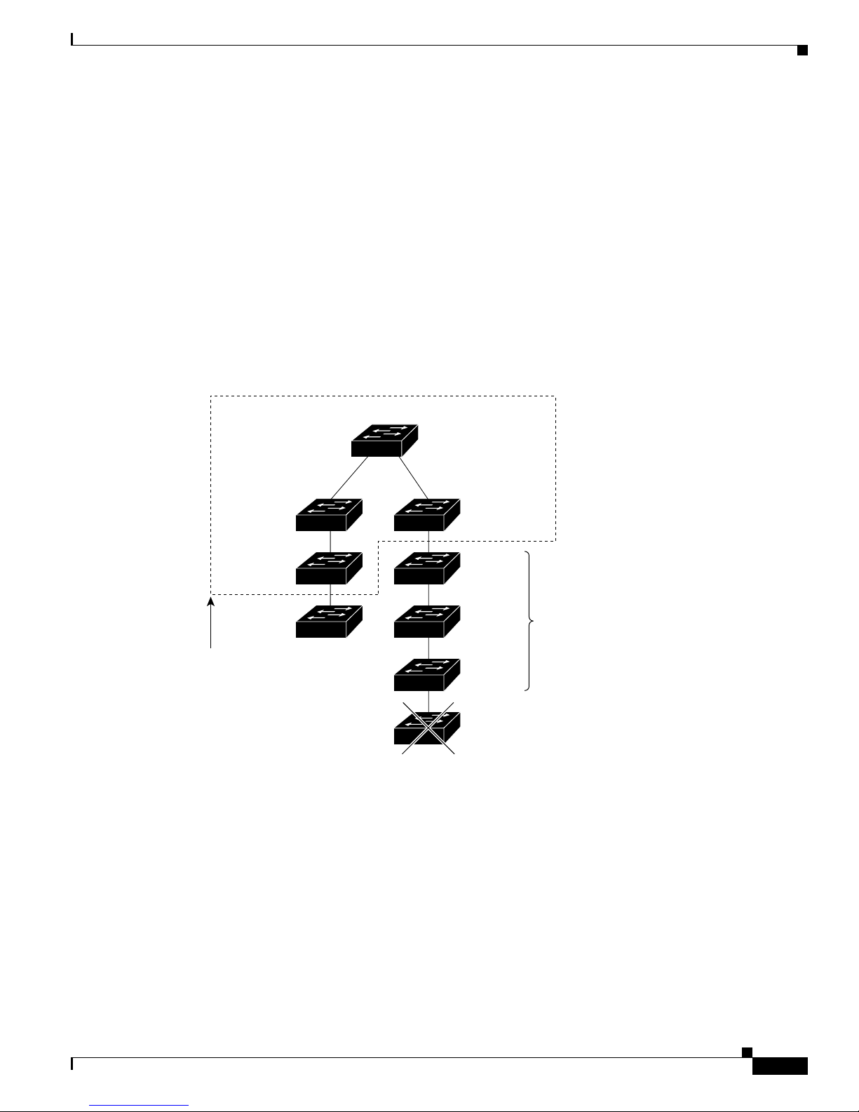
Chapter 5 Clustering Switches
Discovery through CDP Hops
ByusingCDP,acommandswitchcandiscoverswitchesuptosevenCDPhopsaway(thedefaultis
three hops) fr om t he edge of the cluster. The edge of the cluster is where the last member switc hes are
connected to the cluster (for example, the command switch and member switches 8, 9, and 10 in
Figure 5-1 are a t t he edge of the cluster).
Yo u can set the number of ho ps the comman d s witc h s ea rche s f or candidate an d member switc hes by
selecting Cluster > Hop Count. When new candidate switches are added to the network, the command
switch discovers them and adds them to the list of candidate switches.
Figure 5-1 shows a switch cluster with candidate switches. The command switch has ports assigned to
management VLAN 16. The CDP hop count is three. The command switch discovers switches 1 1, 12 ,
13, and 14 b eca use t hey are within 3 hops from the edge of the cluster. It does not disc over switc h 1 5
because it is 4 hops from the edge of the cluster.
Figure 5-1 Discovery through CDP Hops
Planning a Switch Cluster
Command switch
Switch 11
candidate
Edge of
cluster
Management
VLAN 16
Member
switch 8
Member
switch 9
switch
Management
VLAN 16
Member
switch 10
Switch 12
Switch 13
Switch 14
Switch 15
Candidate
switches
65281
78-11380-03
Catalyst 2950Desktop Switch Software Configuration Guide
5-5
Page 100

Planning a Switch Cluster
Discovery through Non-CDP-Capable and Noncluster-Capable Devices
If a command switch is conn ec ted to a non-CDP -capa ble third-party hub (such as a non-Cisco hub), it
can disc over cluster-enabled devices connec ted to that thir d-p ar ty hub. However, if the command switch
is connected to a noncluste r-capable Cisco device, it cannot discover cluster-enabled device connected
to that noncl uste r-capabl e C is co device.
Figure 5-2 shows that the command switch discovers the Catalyst 3500 XL switch, which is connected
to a third-pa rty hub. However, t he command swit ch d oes not discover the Catalyst 2950 sw itch that is
connected to a Catalyst 5000 switch.
Figure 5-2 Discovery through Non-CDP-Capable and Noncluster-Capable Devices
Command switch
Chapter5 Clustering Switches
Third-party hub
(non-CDP-capable)
Catalyst 3500 XL
candidate switch
Catalyst 5000 switch
(noncluster-capable)
Catalyst 2950
candidate switch
65290
Catalyst 2950Desktop Switch Software Configuration Guide
5-6
78-11380-03
 Loading...