

Page 1
Cisco Catalyst 2950 Series
Fast Ethernet Desktop Switches
DATA SHEET
Overview
The Cisco Catalyst® 2950 Series of fixed
configuration, wire-speed Fast Ethernet desktop
switches delivers premium performance and
functionality for local-area networks (LANs). These
standalone, 10/100 autosensing switches provide
enhanced quality of service (QoS) and multicast
management features—managed with the
easy-to-use, Web-based Cisco Cluster Management
®
Suite (CMS) and integrated Cisco IOS
The Catalyst 2950 Gigabit-over-copper version with
10/100/1000BaseT uplinks offers medium-sized
businesses andenterprise branchoffices with an ideal
solution to migrate from Fast Ethernet to a
higher-performance Gigabit Ethernet backbone using
existing Category 5 copper cabling.
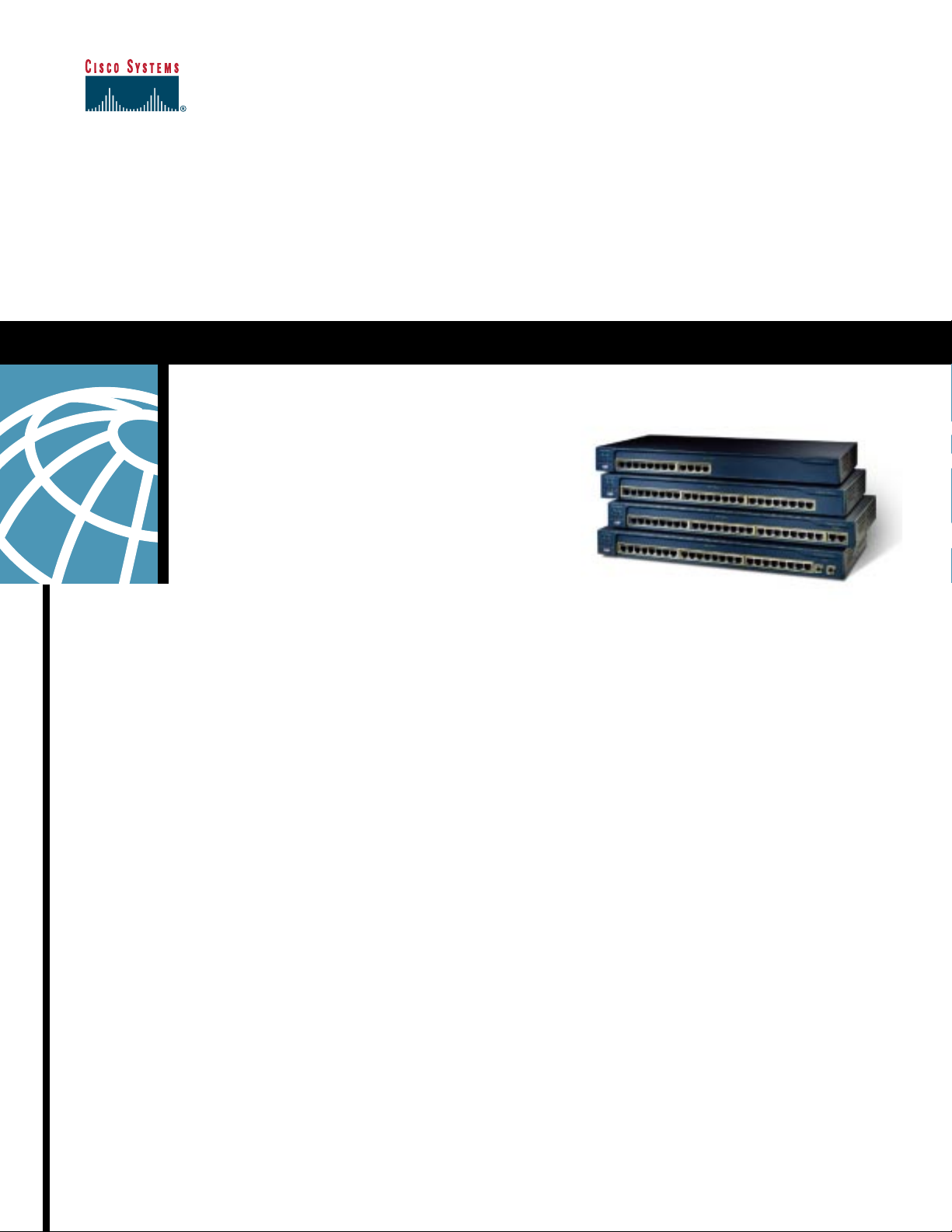
The Catalyst 2950 Series consists of the Catalyst
2950T-24, 2950-24, 2950-12, and 2950C-24 switches.
The Catalyst 2950-24 Switch provides 24 10/100
ports; the 2950-12 has 12 10/100 ports; the 2950T-24
has 24 10/100 ports with 2 fixed 10/100/1000BaseT
uplink ports; and the 2950C-24 has 24 10/100 ports
with2 fixed 100BaseFXuplinkports. Each switchhas
a one rack-unit (RU) form factor, making them very
flexible to deploy, either on a desktop ormounted ina
wiring closet (Figure 1).
Software.
Figure 1 Catalyst 2950 Series 10/100/1000 Switches
Wire-Speed Performance in Connecting End-Stations to the LAN
With a switching fabric of 8.8 Gigabits per second
(Gbps) and a maximum forwarding bandwidth of 4.4
Gbps, the Catalyst 2950 switches deliver wire-speed
performance on all ports in connecting end-stations
and users to the company LAN.
Catalyst 2950 switchessupport performance boosting
®
features such as Fast EtherChannel
EtherChannel technology, offering up to 4-Gbps of
high-performance bandwidth between Catalyst
switches, routers, and servers.
and Gigabit
Cisco Systems, Inc.
All contents are Copyright © 1992–2001 Cisco Systems, Inc. All rights reserved. Important Notices and Privacy Statement.
Page 1 of 9
Page 2

Migrate to Gigabit Speeds in the LAN
Midmarket customers who have e xisting copper (Category 5,
UTP) wiring infrastructure in their buildings no w have a truly
compellingsolution tomigrate to Gigabitspeeds in theirLANs.
The Catalyst 2950T-24 deliv ers tw o fixed 10/100/1000BaseT
(Gigabit-Ethernet-over-copper) uplink ports in addition to
24 10/100 ports for desktop connectivity. For a fractional
increment in price per port, midsized businesses can now
upgrade their LANs to higher-performance Gigabit Ethernet.
Multicast Management via IGMP Snooping
The Internet Group Management Protocol (IGMP) Snooping
feature allows the switch to “listen in” on the IGMP
conversation between hosts and routers. When a switch hears
an IGMPjoin request froma host for a givenmulticast group,
the switch adds the host’s port number to the Group
Destination Address (GDA) list for that group. And,when the
switch hears an IGMP leaverequest, it removesthe host’sport
from the Content Addressable Memory (CAM) table entry.
In conjunction with the new Catalyst 3550-12T multilayer
Gigabit Ethernet switch,the Catalyst 2950T-24switch provides
an integrated Gigabit-Ethernet-over-copper solution for
midmarket customers who have outgrown their Fast Ethernet
backbones.
Sophisticated Quality of Service
The Catalyst 2950 Series delivers sophisticated LAN-edge
QoS, unmatched inits category ofproducts in theindustry.All
Catalyst 2950switches support two modes of reclassification.
One mode—based on the IEEE 802.1p standard—honors the
class-of-service (CoS) value at the ingress point and assigns
the packet to the appropriate queue. In the second mode,
packets can be reclassified based on a default CoS value
assigned to the ingress port by the network administrator. In
the case of frames that arrive without a CoS value (such as
untagged frames), Catalyst 2950 switches support
classification based on a default CoS value per port assigned
by the network administrator.
Once theframes havebeen classified or reclassified usingone
of the abovemodes,they are assignedto the appropriatequeue
at the egress. Catalyst 2950 switches support four egress
queues, which allow the network administrator to be more
discriminating and granular in assigning priorities for the
various applications on the LAN traffic. Strict Priority
Scheduling configuration ensures time-sensitive applications
such as voice, always follow an expedited path through the
switch fabric. Weighted Round Robin (WRR) scheduling,
another significant enhancement, ensures that lower-priority
traffic receives attention without comprising the priority
settings administered by a network manager.
By supporting IGMP Snooping in hardware andconfiguration
of IGMP Snooping via the Cisco Cluster Management Suite,
Catalyst 2950 switches deliver outstanding performance and
ease of use in administering and managing multicast
applications on the LAN.
Cisco Cluster Management Suite
The Cisco Cluster Management Suite (CMS) is Web-based
software that is embedded in Catalyst 2950, 3550-12T, 3500
XL, 2900 XL, and 1900 switches. Through Cisco Switch
Clustering technology, users access CMS with any standard
Web browser to manage up to 16 interconnected Catalyst
2950, 3550-12T, 3500 XL, 2900 XL, and 1900 switches at
once—regardless of their geographic proximity—using a
single-IP address. CMS provides an integrated management
interface for all Cisco IOS functionality, firmware
management, and offers administrators a powerful graphical
user interface (GUI) tool to easily monitor and manage their
LANs.
CMS supports a broad range of standards-based connectivity
options and configurations to deliver levels of performance
that are scalable to meet customer requirements. Switch
Cluster connectivity options for Catalyst 2950 switches
include Ethernet, Fast Ethernet, Fast EtherChannel, Gigabit
Ethernet (1000BaseT), and Gigabit EtherChannel
connectivity. Because the technology is not limited by
proprietary stacking modules or stacking cables, CMS
expands the traditional cluster domain beyond a single wiring
closet and lets users mix and match interconnections to meet
specific management, performance, and cost requirements.
These features allow network administrators to prioritize
mission-critical, time-sensitive traffic, such as ERP (Oracle,
SAP, and so on), voice (IP telephony traffic), and CAD/CAM
over less time-sensitive applications such as FTP or e-mail
(SMTP).
Cisco Systems, Inc.
All contents are Copyright © 1992–2001 Cisco Systems, Inc. All rights reserved. Important Notices and Privacy Statement.
Page 2 of 9
Page 3

Catalyst 2950 switches can be configured either as command
or member switches in a Cisco switch cluster. The command
switch serves as the single-IP address management point and
disbursesall managementinstructionsdictated bythe network
administrator. Command switches can cluster up to 15
additional interconnected member switches regardless of
interconnection media. CMS also allows the network
administrator to designate a standby or redundant command
switch, which takes thecommander dutiesshould the primary
command switch fail.
Enhanced Security, Management, and Integrated Cisco IOS Features
Cisco Catalyst 2950 Series switches have several exceptional
features toincrease network performance, manageability,and
security. Network managers can implement higher levels of
data security and boost LAN performance by deploying up to
64 virtual LANs (VLANs) per switch. This ensures that data
packets are forwarded only to stations within a specific
VLAN, creating a virtual firewall between groups of ports on
the network and reducing broadcast transmission.
VLAN trunks can be created from any port using the
standards-based 802.1Q VLAN trunking architecture. Per
VLAN Spanning Tree (PVST+) allows users to implement
redundant uplinks while also distributing traffic loads across
multiple links. This is not possible with standard Spanning
Tree Protocol (STP) implementations. Cisco Uplink Fast
technology ensures immediate transfer to the secondary
uplink, much better than the traditional 30 to 60 second
convergence time. Thisis yetanother enhancement ofthe STP
implementation.
With Catalyst 2950 switches, network managers can
implement high levels of port and console security. Media
Access control (MAC) address-based port level security
prevents unauthorized stations from accessing the switch.
Static and dynamic address limits can be created, giving
administrators powerful control over network access.
Multilevel access security on the switch console prevents
unauthorized users from accessing or altering switch
configuration. Terminal access controller access control
system (TACACS+) authentication enables centralized
coordination of access control across a large group of
networking devices.
Features And Key Benefits
Exceptional Performance
• Wire-speed, nonblocking performance on all ports,
including Gigabit ports
• 8.8-Gbps switching fabric and 6.6 million
packets-per-second maximum forwarding rate ensures
maximum throughput—even for the most
performance-sensitive applications
• 12- or 24- 10BaseT/100BaseTX autosensing ports, each
delivering up to 200 Mbps of bandwidth to individual
users, servers or workgroups to support
bandwidth-intensive applications
• Catalyst 2950T-24 has two built-in, Gigabit Ethernet
(1000BaseT) ports that deliver up to 4 Gbps aggregated
bandwidth to the Gigabit Ethernet backbone, Gigabit
Ethernetservers or between switches—leveragingexisting
Category 5 cabling infrastructure—up to a distance of 100
meters
• Catalyst 2950C-24 switch has two multimode
(100BaseFX) fiber uplinks deliver up to 200 Mbps
of bandwidth over an extended distance of up to 2
kilometers
• 8 MB shared memory architecture ensures the highest
possible throughput with a design that eliminates
head-of-line blocking, minimizes packet loss,and delivers
better overall performancein environments with extensive
multicast and broadcast traffic
• 16 MB of DRAM and 8 MB of Flash on-board enable the
addition of future feature upgrades, maximizing customer
investments
• Bandwidth aggregation through Fast EtherChannel and
GigabitEtherChannel technologyenhancesfault tolerance
and offersup to 4Gbps of aggregatedbandwidth between
switches, to routers and to individual servers
• 802.1Q standards-based VLAN trunking on each port; 64
VLANs per switch with 64 instances of Spanning Tree
(PVST+)
• Superior multicast management via support for IGMP
snooping in hardware
Cisco Systems, Inc.
All contents are Copyright © 1992–2001 Cisco Systems, Inc. All rights reserved. Important Notices and Privacy Statement.
Page 3 of 9
Page 4

QoS
• Support for reclassifying frames based either on 802.1p
CoS value or default CoS value per port assigned by
network manager
• Four queues per egress port supported in hardware
• WRR queuing algorithm ensures low priority queues are
not starved
• Strict Priority Scheduling configuration ensures
time-sensitiveapplications suchas voicealways follow an
expedited path through the switch fabric
Ease-of-Use and Ease-of-Deployment
• Cisco CMS allows the network administrator to manage
up to 16 interconnected Catalyst 2950, 3550-12T, 3500
XL, 2900 XL, and 1900 switches through a single IP
address, using anystandard Web browserregardlessof the
location ofthe switches—that is,the switches donot have
to be physically located in the same wiring closet
• Full backward compatibility ensures that any Catalyst
3500 XL, Catalyst 2900 XL, or Catalyst 1900 switch can
be managed with a Catalyst 2950 using the Cisco CMS
• Cluster software upgrade feature allows the user to
automatically upgrade the system software on a group of
Catalyst 3550-12T, Catalyst 2950, Catalyst 3500 XL, and
Catalyst 2900 XL switches
• Autosensing on each port detects thespeed ofthe attached
device and automatically configures the port for 10-, 100or 1000-Mbps operation, easing switch deployment in
mixed 10-, 100-, and 1000BaseT environments
• Autonegotiating on all ports automatically selects half- or
full-duplex transmission mode to optimize bandwidth
• Default configuration stored in Flash memory ensures the
switch is quickly connected to the network and can pass
traffic with minimal user intervention
Integrated Cisco IOS Switching Solution
• Bandwidth aggregation through Fast EtherChannel and
GigabitEtherChannel technologyenhancesfault tolerance
and offers upto 4Gbps of bandwidth between switches,to
routers and individual servers
• Per-port broadcast storm control prevents faulty end
stations from degrading overall systemsperformance with
broadcast storms
• Command line interface (CLI) support provides a user
interface and command set, which is common across all
Catalyst switches and Cisco routers
• Cisco Discovery Protocol (CDP) enables a CiscoWorks
networkmanagement stationto automatically discoverthe
switch in a network topology
Superior Manageability
• Cisco CMS allows the network administrator to manage
up to 16 interconnected Catalyst 2950, 3550-12T, 3500
XL, 2900 XL, and 1900 switches through a single IP
address and any standard Web browser, regardless of the
location ofthe switches—that is,the switches donot have
to be physically located in the same wiring closet
• Switch clustering software upgrade allows network
administrators to upgrade the system software of up to 16
interconnected switches through the easy-to-use Cisco
CMS interface or a single CLI command
• Simple Network Management Protocol (SNMP),
and Telnet interface support delivers comprehensive
in-band management, and a CLI-based management
console provides detailed out-of-band management
• Manageable through CiscoWorks Windows network
management software on a per-port and per-switch basis
providing a common management interface for Cisco
routers, switches, and hubs
• Embedded Remote Monitoring (RMON) software agent
supports four RMON groups (History, Statistics, Alarms
and Events) forenhanced traffic management,monitoring,
and analysis
Cisco Systems, Inc.
All contents are Copyright © 1992–2001 Cisco Systems, Inc. All rights reserved. Important Notices and Privacy Statement.
Page 4 of 9
Page 5

• Switch Port Analyzing (SPAN) port monitors traffic of a
single port from a single network analyzer or RMON
probe
• Autoconfiguration eases deployment of switches in
the network by automatically configuring multiple
switches across a network via a boot server
• Domain Name Services (DNS) provide IP address
resolution with user-defined device names
• Trivial File Transfer Protocol (TFTP) reduces the cost of
administering software upgrades by downloading from a
centralized location
• Network Time Protocol (NTP) provides an accurate and
consistent timestamp to all switches within the intranet
• Spanning Tree Root Guard (STRG)prevents edge devices
that are not in the network administrator’s control from
becoming STP root nodes
• Multi-function LEDs per port for Port Status, half-duplex/
full-duplex, 10BaseT/100BaseTX/1000BaseT indication
as well as switch-level status LEDs for system, RPS, and
bandwidth utilization provide a comprehensive and
convenient visual management system
Security and Redundancy
• IEEE 802.1x support (planned future software support)
• Cisco Uplink Fast technology ensures quick fail-over
(typically fewer than 3 seconds) recovery enhancing
overall network stability and reliability
• Multilevel security on console access prevents
unauthorized users from altering the switch configuration
• Support for TACACS+authentication enables centralized
control of the switch and restricts unauthorized users from
altering the configuration
Technical Specifications
Performance
• 8.8-Gbps switching fabric
• Forwarding Rates based on 64-byte packets
– Catalyst 2950-12: 1.8 Mpps wire-speed forwarding
rate
– Catalyst 2950-24: 3.6 Mpps wire-speed forwarding
rate
– Catalyst 2950T-24: 6.6 Mpps wire-speed
forwarding rate
– Catalyst 2950C-24: 3.9 Mpps wire-speed
forwarding rate
• 4.4-Gbps maximum forwarding bandwidth
• 8 MB packet buffermemory architecture shared by all ports
• 16 MB DRAM and 8 MB Flash memory
• 8,000 MAC addresses
Management
• SNMP Management Information Base (MIB) II, SNMP
MIB extensions, Bridging MIB (RFC 1493)
• Private VLAN Edge provides security and isolation
between ports on a switch, ensuring that voice traffic
travels directly from its entry point to the aggregation
device through a virtual path and cannot be directed to a
different port
• MAC-based port level security prevents unauthorized
stations from accessing the switch
• User-selectable address learning mode simplifies
configuration and enhances security
• IEEE 802.1D STP support for redundant backbone
connections and loop-free networks simplifies network
configuration and improves fault tolerance
• Support for the CiscoRedundant PowerSystem 300 (RPS
300), which provides a backup internal power supply for
up to six units, provides improved fault tolerance and
network uptime
Cisco Systems, Inc.
All contents are Copyright © 1992–2001 Cisco Systems, Inc. All rights reserved. Important Notices and Privacy Statement.
Page 5 of 9
Page 6

Standards
• IEEE 802.1x support (planned future software support)
• IEEE 802.3x full duplex on 10BaseT, 100BaseTX, and
1000BaseT ports
• IEEE 802.1D Spanning-Tree Protocol
• IEEE 802.1p CoS
• IEEE 802.1Q VLAN
• IEEE 802.3ab 1000BaseT specification
• IEEE 802.3u 100BaseTX specification
• IEEE 802.3 10BaseT specification
Y2K
• Y2K compliant
Connectors and Cabling
• 10BaseT ports: RJ-45 connectors, two-pair Category 3, 4,
or 5 unshielded twisted-pair (UTP) cabling
• 100BaseTX ports: RJ-45 connectors; two-pair Category 5
UTP cabling
• 1000BaseT ports: RJ-45 connectors; two-pair Category 5
UTP cabling
• 100BaseFX ports: MT-RJ connectors, 10/125 or 62.5/125
micron multi-mode fiber-optic cabling
• Management console port: 8-pin RJ-45 connector,
RJ-45-to-RJ-45 rollover cable with RJ-45-to-DB9 adapter
for PC connections. For terminal connections, use
RJ-45-to-DB25 female DTE adapter (can be ordered
separately from Cisco. Part Number: ACS-DSBUSYN=)
MT-RJ Patch Cables (Type of Cable, Cisco Part Number)
• 1-meter, MT-RJ-to-SC multimode cable,
CAB-MTRJ-SC-MM-1M
• 3-meter, MT-RJ-to-SC multimode cable,
CAB-MTRJ-SC-MM-3M
• 5-meter, MT-RJ-to-SC multimode cable,
CAB-MTRJ-SC-MM-5M
Power Connectors
Youcan provide power to a switch either by usingthe internal
power supply or the Cisco RPS 300. The connectors are
located at the back of the switch.
Internal Power Supply Connector
• The internal power supply is an autoranging unit
• Supports input voltages between 100 and 240 VAC
• Use the supplied AC power cord to connect the AC power
connector to an AC power outlet
Cisco RPS Connector
• Connection for an optional Cisco RPS 300 that uses AC
input and supplies DC output to the switch
• 300-watt redundant power system that can support six
external network devicesand providespower to one failed
device at a time
• Automatically senses when the internal power supply ofa
connected device fails and provides power to the failed
device, preventing loss of network traffic
• When internal power supply has been brought up or
replaced, the RPS 300 automatically stops powering the
device
• Attach only the Cisco RPS 300 (model
PWR300-AC-RPS-N1) to the RPS receptacle
Indicators
• Per-port status LEDs: link integrity, disabled, activity,
speed, and full-duplex indications
• System status LEDs: system, RPS, and bandwidth
utilization indications
Dimensions and Weight (H x W x D)
• Dimensions: 1.72 x 17.5 x 9.52 in. (4.36 x 44.45 x 24.18
cm)
• One rack-unit (RU) high (1.72 in./4.36 cm)
• Weight: 6.5 lbs (3.0 kg)
• 1-meter, MT-RJ-to-ST multimode cable,
CAB-MTRJ-ST-MM-1M
• 3-meter, MT-RJ-to-ST multimode cable,
CAB-MTRJ-ST-MM-3M
• 5-meter, MT-RJ-to-ST multimode cable,
CAB-MTRJ-ST-MM-5M
All contents are Copyright © 1992–2001 Cisco Systems, Inc. All rights reserved. Important Notices and Privacy Statement.
Cisco Systems, Inc.
Page 6 of 9
Page 7

Environmental Conditions and Power Requirements
Environmental Ranges
• Operating temperature: 23 to 113 F (-5º C to 45 C)
Regulatory Agency Approvals
Safety Certifications
• UL/CSA G0950 Third Edition
• Storage temperature: -13 to 158 F (-25 to 70 C)
• Operating relative humidity: 10 to 95% (non-condensing)
• Operating altitude: Up to 10,000 ft (3,000 m)
• Storage Altitude: Up to 15,000 ft (4,500 m)
Power Requirements
• Power consumption: 30W (maximum), 102 BTUs
per hour
• ACinputvoltage/frequency:100 to127or 200 to240 VAC
(auto-ranging), 50 to 60 Hz
• DC Input Voltages: +12V @ 4.5A
Fiber-port Specifications (Catalyst 2950C-24)
• Optical Transmitter Wavelength: 1300 nm (nanometers)
• Optical receiver sensibility: –14dBm (decibel milliwatt)
• Optical transmitter power: –19dBm to –14 dBm
• Transmit: –19 dBm to –14dBm
Mean Time Between Failure (MTBF) Predictions
Part Number MTBF Predictions (Hours)
• CSA 22.2 No. 950
• EN 60950
• IEC 950
• AS/NZS 3260, TS001
• CE Marking
Electromagnetic Emissions Certifications
• FCC Part 15 Class A
• EN 55022 Class A (CISPR 22 Class A)
• VCCI Class A
• AS/NZS 3548 Class A
• CE Marking
• CLEI Code
• BSMI Class A
Warranty
• Lifetime limited warranty
WS-C2950T-24 297,144
WS-C2950-24 268,292
WS-C2950C-24 268,292
WS-C2950-12 318,440
Cisco Systems, Inc.
All contents are Copyright © 1992–2001 Cisco Systems, Inc. All rights reserved. Important Notices and Privacy Statement.
Page 7 of 9
Page 8

Service and Support
The services and support programs described in the table below are available as part of the Cisco Desktop Switching Service and
Support solution.
Service and Support Features Benefits
Rapid Deployment Tools and Service
Total Implementation Solutions • Project management
• Site survey, configuration deployment
• Installation, text, and cutover
• Training
• Major Moves, Adds, Changes
• Design review and product staging
Core Service and Support
•TAC
• SMARTnet™ support
• SMARTnet Onsite (OS) support
Advanced Service and Support
Solution Packages
Cisco Business Essential Solution (BES) • Comprehensive solution that includes
Cisco Business Critical Solution (BCS) • Comprehensive high availability solution that
• 24x7 access to software updates
• Web access to technical repositories
• Telephone support through the Technical
Assistance Center
• Advance replacement of hardware parts
Network Supported Accounts (NSA)
Program, ETAC Relationship Manager,
SMARTnet and SMARTnet Onsite support,
Cisco Interactive Mentor (complete library;
five user licenses)
includes: Complete Business Essential
Solution, Service Delivery Manager,
NSA-High-Availability Services (NSA-HAS)
Program and Network Availability SAL, 24x7
access to ETAC and CIM enterprise-wide
license
• Supplements existing staff
• Ensures functionality meets needs
• Mitigates risk
• Enables proactive or expedited issue
resolution
• Lowers cost of ownership by utilizing Cisco
expertise and knowledge
• Minimize network downtime
• Maximizes network stability and performance
• Ensures Seamless Change management
• Augments internal networking staff
• Deploys solutions and technologiesfasterwith
less risk
• Fully optimize network to achieve business
goals and ahead of competitors
• Increase control over network operations
• Proactively drive high network availability
Ordering Information
Model Numbers
• WS-C2950-12: 12 10/100 ports
• WS-C2950-24: 24 10/100 ports
• WS-C2950T-24: 24 10/100 ports + 2 10/100/1000BaseT ports
• WS-C2950C-24: 24 10/100 ports + 2 100BaseFX ports
Cisco Systems, Inc.
All contents are Copyright © 1992–2001 Cisco Systems, Inc. All rights reserved. Important Notices and Privacy Statement.
Page 8 of 9
Page 9

For More Information
• US and Canada: 800 553-NETS (6387)
• Europe: 32 2 778 4242
• Australia: 612 9935 4107
• Other: 408 526-7209
• www.cisco.com
Corporate Headquarters
Cisco Systems, Inc.
170 West Tasman Drive
San Jose, CA 95134-1706
USA
www.cisco.com
Tel: 408 526-4000
800 553-NETS (6387)
Fax: 408 526-4100
Cisco Systems has more than 200 offices in the following countries and regions. Addresses, phone numbers, and fax numbers are listed on the
European Headquarters
Cisco Systems Europe
11, Rue Camille Desmoulins
92782 Issy-les-Moulineaux
Cedex 9
France
www.cisco.com
Tel: 33 1 58 04 60 00
Fax: 33 1 58 04 61 00
Americas Headquarters
Cisco Systems, Inc.
170 West Tasman Drive
San Jose, CA 95134-1706
USA
www.cisco.com
Tel: 408 526-7660
Fax: 408 527-0883
Asia Pacific Headquarters
Cisco Systems Australia, Pty., Ltd
Level 9, 80 Pacific Highway
P.O. Box 469
North Sydney
NSW 2060 Australia
www.cisco.com
Tel: +61 2 8448 7100
Fax: +61 2 9957 4350
Cisco.com Web site at www.cisco.com/go/offices.
Argentina • Australia • Austria • Belgium • Brazil • Bulgaria • Canada • Chile • China PRC • Colombia • Costa Rica • Croatia • Czech Republic
Denmark • Dubai, UAE • Finland • France • Germany • Greece • Hong Kong SAR • Hungary • India • Indonesia • Ireland • Israel
Italy • Japan • Korea • Luxembourg • Malaysia • Mexico • The Netherlands • New Zealand • Norway • Peru • Philippines • Poland • Portugal
Puerto Rico • Romania • Russia • Saudi Arabia • Scotland • Singapore • Slovakia • Slovenia • South Africa • Spain • Sweden
Switzerland • Taiwan • Thailand • Turkey • Ukraine • United Kingdom • United States • Venezuela • Vietnam • Zimbabwe
All contents are Copyright © 1992–2001 Cisco Systems, Inc. All rights reserved. Important Notices and Privacy Statement. Printed in the USA. SMARTnet is a trademark of Cisco Systems, Inc.; Catalyst, Cisco, tCisco IOS,
Cisco Systems, the Cisco Systems logo, and EtherChannel are registered trademarks of Cisco Systems, Inc. or its affiliates in the U.S. and certain other countries.
All other brands, names, or trademarks mentioned in this document or Web site are the property of their respective owners. The use of the word partner does not imply a partnership relationship between Cisco and any
other company. (0101R) 04/01 BW7180
 Loading...