

Page 1

Cisco 1800 Series Integrated Services
Routers (Fixed) Hardware Installation
Guide
Americas Headquarters
Cisco Systems, Inc.
170 West Tasman Drive
San Jose, CA 95134-1706
USA
http://www.cisco.com
Tel: 408 526-4000
800 553-NETS (6387)
Fax: 408 527-0883
Text Part Number: OL-6425-03
Page 2

THE SPECIFICATIONS AND INFORMATION REGARDING THE PRODUCTS IN THIS MANUAL ARE SUBJECT TO CHANGE WITHOUT NOTICE. ALL
STATEMENTS, INFORMATION, AND RECOMMENDATIONS IN THIS MANUAL ARE BELIEVED TO BE ACCURATE BUT ARE PRESENTED WITHOUT
WARRANTY OF ANY KIND, EXPRESS OR IMPLIED. USERS MUST TAKE FULL RESPONSIBILITY FOR THEIR APPLICATION OF ANY PRODUCTS.
THE SOFTWARE LICENSE AND LIMITED WARRANTY FOR THE ACCOMPANYING PRODUCT ARE SET FORTH IN THE INFORMATION PACKET THAT
SHIPPED WITH THE PRODUCT AND ARE INCORPORATED HEREIN BY THIS REFERENCE. IF YOU ARE UNABLE TO LOCATE THE SOFTWARE LICENSE
OR LIMITED WARRANTY, CONTACT YOUR CISCO REPRESENTATIVE FOR A COPY.
The following inform ation is for FCC compliance of Class A devices: This equipment has been tested and found to comply with the limits for a Class A digital device, pursuant
to part 15 of the FCC rules. These limits are designed to provide reasonable protection against harmful interference when the equipment is operated in a commercial
environment. This equipment generates, uses, and can radiate radio-frequency energy and, if not installed and used in accordance with the instruction manual, may cause
harmful interference to radio communications. Operation of this equipment in a residential area is likely to cause harmful interference, in which case users will be required
to correct the interference at their own expense.
The following information is for FCC compliance of Class B devices: The equipment described in this manual generates and may radiate radio-frequency energy. If it is not
installed in accordance with Cisco’s installation instructions, it may cause interference with radio and television reception. This equipment has been tested and found to
comply with the limits for a Class B digital device in accordance with the specifications in part 15 of the FCC rules. These specifications are designed to provide reasonable
protection against such interference in a residential installation. However, there is no guarantee that interference will not occur in a particular installation.
Modifying the equipment without Cisco’s written authorization may result in the equipment no longer complying with FCC requirements for Class A or Class B digital
devices. In that event, your right to use the equipment may be limited by FCC regulations, and you may be required to correct any interference to radio or television
communications at your own expense.
You can determine whether your equipment is causing interference by turning it off. If the interference stops, it was probably caused by the Cisco equipment or one of its
peripheral devices. If the equipment causes interference to radio or television reception, try to correct the interference by using one or more of the following measures:
• Turn the television or radio antenna until the interference stops.
• Move the equipment to one side or the other of the television or radio.
• Move the equipment farther away from the television or radio.
• Plug the equipment into an outlet that is on a different circuit from the television or radio. (That is, make certain the equipment and the television or radio are on circuits
controlled by different circuit breakers or fuses.)
Modifications to this product not authorized by Cisco Systems, Inc. could void the FCC approval and negate your authority to operate the product.
The Cisco implementation of TCP header compression is an adaptation of a program developed by the University of California, Berkeley (UCB) as part of UCB’s public
domain version of the UNIX operating system. All rights reserved. Copyright © 1981, Regents of the University of California.
NOTWITHSTANDING ANY OTHER WARRANTY HEREIN, ALL DOCUMENT FILES AND SOFTWARE OF THESE SUPPLIERS ARE PROVIDED “AS IS” WITH
ALL FAULTS. CISCO AND THE ABOVE-NAMED SUPPLIERS DISCLAIM ALL WARRANTIES, EXPRESSED OR
LIMITATION, THOSE OF MERCHANTABILITY, FITNESS FOR A PARTICULAR PURPOSE AND NONINFRINGEMENT OR ARISING FROM A COURSE OF
DEALING, USAGE, OR TRADE PRACTICE.
IN NO EVENT SHALL CISCO OR ITS SUPPLIERS BE LIABLE FOR ANY INDIRECT, SPECIAL, CONSEQUENTIAL, OR INCIDENTAL DAMAGES, INCLUDING,
WITHOUT LIMITATION, LOST PROFITS OR LOSS OR DAMAGE TO DATA ARISING OUT OF THE USE OR INABILITY TO USE THIS MANUAL, EVEN IF CISCO
OR ITS SUPPLIERS HAVE BEEN ADVISED OF THE POSSIBILITY OF SUCH DAMAGES.
CCDE, CCENT, Cisco Eos, Cisco Lumin, Cisco Nexus, Cisco StadiumVision, Cisco TelePresence, Cisco WebEx, the Cisco logo, DCE, and Welcome to the Human Network
are trademarks; Changing the Way We Work, Live, Play, and Learn and Cisco Store are service marks; and Access Registrar, Aironet, AsyncOS, Bringing the Meeting To
You, Catalyst, CCDA, CCDP, CCIE, CCIP, CCNA, CCNP, CCSP, CCVP, Cisco, the Cisco
Cisco
Systems Capital, the Cisco Systems logo, Cisco Unity, Collaboration Without Limitation, EtherFast, EtherSwitch, Event Center, Fast Step, Follow Me Browsing,
FormShare, GigaDrive, HomeLink, Internet Quotient, IOS, iPhone, iQuick Study, IronPort, the IronPort
MeetingPlace Chime Sound, MGX, Networkers, Networking Academy, Network Registrar, PCNow, PIX, PowerPanels, ProConnect, ScriptShare, SenderBase, SMARTnet,
Spectrum Expert, StackWise, The Fastest Way to Increase Your Internet Quotient, TransPath, WebEx, and the WebEx
and/or its affiliates in the United States and certain other countries.
All other trademarks mentioned in this document or website are the property of their respective owners. The use of the word partner does not imply a partnership relationship
between Cisco and any other company. (0809R)
Cisco 1800 Series Integrated Services Routers (Fixed) Hardware Installation Guide
Copyright ©2005-2008 Cisco Systems, Inc. All rights reserved.
Certified Internetwork Expert logo, Cisco IOS, Cisco Press, Cisco Systems,
logo, LightStream, Linksys, MediaTone, MeetingPlace,
IMPLIED, INCLUDING, WITHOUT
logo are registered trademarks of Cisco Systems, Inc.
Page 3

Preface iii-vii
Objectives iii-vii
Audience iii-vii
Conventions iii-viii
Safety Warnings iii-viii
Warning Definition iii-ix
Related Documentation iii-xiv
Cisco One-Year Limited Hardware Warranty Terms iii-xiv
iii-xvi
CONTENTS
CHAPTER
1 Overview 1-1
Hardware Features 1-2
Product Serial Number Location 1-2
Feature Summary 1-2
Memory 1-3
Power 1-4
LED Indicators 1-4
Integrated 802.11a/b/g Radio Module (Wireless Models Only) 1-5
Supported Cisco Radio Antennas (Wireless Models Only) 1-6
Chassis Ventilation 1-6
Real-Time Clock 1-6
Kensington Lock 1-7
Chassis Views 1-7
Cisco 1811 Chassis 1-9
Cisco 1812 Chassis 1-10
Interface Numbering 1-11
Specifications 1-12
Cisco Product Identification Tool 1-2
Regulatory Compliance 1-13
CHAPTER
2 Preinstallation Requirements 2-1
Safety Recommendations 2-2
Safety with Electricity 2-2
OL-6425-03
Cisco 1800 Series Integrated Services Routers (Fixed) Hardware Installation Guide
iii
Page 4

Contents
Preventing Electrostatic Discharge Damage 2-3
Additional Warnings for Wireless Routers 2-3
General Safety Guidelines for Wireless Routers 2-3
General Site Requirements 2-4
Power Supply Considerations 2-4
Site Environment 2-4
Wireless LAN Considerations 2-4
Site Configuration 2-5
Installation Checklist 2-5
Creating a Site Log 2-6
Inspecting the Router 2-7
Required Tools and Equipment for Installation and Maintenance 2-7
CHAPTER
CHAPTER
3 Chassis Installation Procedures 3-1
Setting Up the Chassis 3-1
Setting a Cisco 1800 Series Fixed-Configuration Router on a Desktop 3-2
Chassis Grounding 3-2
Mounting a Cisco 1800 Series Fixed-Configuration Router on a Wall 3-2
Installing the Chassis Ground Connection 3-3
4 Power, Cable, and Antenna Connection Procedures 4-1
Power Connections 4-1
Connecting Routers to AC Power 4-2
Connecting WAN and LAN Cables 4-2
Preparing to Connect to a Network 4-3
Ethernet Connections 4-4
ISDN BRI Connections 4-4
Ports and Cabling 4-4
Connection Procedures and Precautions 4-5
Connecting to a Console Terminal or Modem 4-5
Console and Auxiliary Port Considerations 4-6
Console Port Connections 4-7
Connecting to the Console Port 4-7
Auxiliary Port Connections 4-7
Connecting to the Auxiliary Port 4-8
Connecting the Radio Antennas to the Wireless Router 4-8
Cisco 1800 Series Integrated Services Routers (Fixed) Hardware Installation Guide
iv
OL-6425-03
Page 5

Contents
CHAPTER
CHAPTER
5 Power-Up and Initial Configuration Procedures 5-1
Powering Up Cisco 1800 Series Fixed-Configuration Routers 5-1
Checklist for Power Up 5-1
Power-Up Procedure 5-2
Verifying the Front Panel LED Indications 5-3
Verifying the Hardware Configuration 5-3
Configuring the Router 5-3
Initial Configuration Using Cisco Router and Security Device Manager 5-4
Initial Configuration Using the Setup Command Facility 5-4
Initial Configuration Using the Cisco CLI—Manual Configuration 5-7
Verifying the Initial Configuration 5-8
Completing the Configuration 5-9
6 Troubleshooting 6-1
Solving Problems 6-1
Troubleshooting the Power and Cooling Systems 6-2
Normal Indications 6-2
Fault Indications 6-2
Environmental Reporting Features 6-3
Troubleshooting Cables and Connections 6-3
CHAPTER
Reading System LEDs 6-4
Reading Port and Connection LEDs 6-4
System Messages 6-6
Recovering a Lost Password 6-7
More Troubleshooting Help—Cisco Technical Assistance Center 6-7
7 Installing and Upgrading Internal Modules 7-1
Safety Warnings 7-1
Removing the Chassis Cover 7-2
Locating Modules 7-3
Installing and Removing DIMMs 7-4
Removing a DIMM 7-4
Installing a DIMM 7-5
Installing the Optional Inline Power Supply 7-5
Installing the Chassis Cover 7-6
Removing and Installing CompactFlash Cards 7-7
Preventing Electrostatic Discharge Damage 7-7
Removing a CompactFlash Memory Card 7-7
OL-6425-03
Cisco 1800 Series Integrated Services Routers (Fixed) Hardware Installation Guide
v
Page 6

I
NDEX
Contents
Installing a CompactFlash Memory Card 7-8
Cisco 1800 Series Integrated Services Routers (Fixed) Hardware Installation Guide
vi
OL-6425-03
Page 7

Preface
This introduction describes the objectives, audience, organization, and conventions of this hardware
document, and points to related documents that provide information beyond the scope of this document.
This preface contains the following sections:
• Objectives, page vii
• Audience, page vii
• Conventions, page viii
• Safety Warnings, page viii
• Related Documentation, page xiv
Objectives
Audience
• Cisco One-Year Limited Hardware Warranty Terms, page xiv
• Obtaining Documentation and Submitting a Service Request, page xvi
This document provides comprehensive hardware-related information about Cisco 1800 series
fixed-configuration integrated services routers, including platform description; information about
safety, site preparation, chassis installation and interconnection, power up, initial configuration, and
troubleshooting; and procedures for maintenance and upgrades.
This document provides enough initial software configuration information to establish network
communication. For detailed software configuration information, see the Cisco 1800 Series Integrated
Services Routers (Fixed) Software Configuration Guide and to the Cisco
command reference publications. These publications are available on line. See the
Documentation and Submitting a Service Request” section for more information.
To access warranty, service, and support information, see the “Cisco One-Year Limited Hardware
Warranty Terms” section.
This documentation is designed for the person installing, configuring, and maintaining the router, who
should be familiar with electronic circuitry and wiring practices and has experience as an electronic or
electromechanical technician. It identifies certain procedures that should be performed only by trained
and qualified personnel.
IOS configuration guides and
“Obtaining
OL-6425-03
Cisco 1800 Series Integrated Services Routers (Fixed) Hardware Installation Guide
vii
Page 8

Preface
Conventions
Conventions
This document uses the conventions listed in Ta bl e 1 to convey instructions and information.
Ta b l e 1 Document Conventions
Convention Description
boldface font Commands and keywords.
italic font Variables for which you supply values.
[ ] Optional keywords or arguments appear in square brackets.
{x | y | z} A choice of required keywords appears in braces separated by vertical bars. You must select one.
screen font Examples of information displayed on the screen.
boldface screen
font
< > Nonprinting characters, for example passwords, appear in angle brackets in contexts where italics are
[ ] Default responses to system prompts appear in square brackets.
Examples of information you must enter.
not available.
Note Means reader take note. Notes contain helpful suggestions or references to material not covered in the
manual.
Timesaver Means the described action saves time. You can save time by performing the action described in the
paragraph.
Tip Means the following information will help you solve a problem. The Tip information might not be
troubleshooting or even an action, but could be useful information, similar to a Timesaver.
Caution Means reader be careful. In this situation, you might do something that could result in equipment
damage or loss of data.
Safety Warnings
Safety warnings appear throughout these publications in procedures that, if performed incorrectly, may
harm you. A warning symbol precedes each warning statement. To see translations of the warnings that
appear in these publications, see the Regulatory Compliance and Safety Information for Cisco 1800
Integrated Services Routers (Fixed) document that accompanied your router.
Cisco 1800 Series Integrated Services Routers (Fixed) Hardware Installation Guide
viii
OL-6425-03
Page 9

Preface
Warning Definition
Safety Warnings
Warning
Waarschuwing
Varoitus
IMPORTANT SAFETY INSTRUCTIONS
This warning symbol means danger. You are in a situation that could cause bodily injury. Before you
work on any equipment, be aware of the hazards involved with electrical circuitry and be familiar
with standard practices for preventing accidents. To see translations of the warnings that appear in
this publication, refer to the translated safety warnings that accompanied this device.
SAVE THESE INSTRUCTIONS
BELANGRIJKE VEILIGHEIDSINSTRUCTIES
Dit waarschuwingssymbool betekent gevaar. U verkeert in een situatie die lichamelijk letsel kan
veroorzaken. Voordat u aan enige apparatuur gaat werken, dient u zich bewust te zijn van de bij
elektrische schakelingen betrokken risico's en dient u op de hoogte te zijn van de standaard
praktijken om ongelukken te voorkomen. Voor een vertaling van de waarschuwingen die in deze
publicatie verschijnen, dient u de vertaalde veiligheidswaarschuwingen te raadplegen die bij dit
apparaat worden geleverd.
Opmerking BEWAAR DEZE INSTRUCTIES.
TÄRKEITÄ TURVALLISUUTEEN LIITTYVIÄ OHJEITA
Tämä varoitusmerkki merkitsee vaaraa. Olet tilanteessa, joka voi johtaa ruumiinvammaan. Ennen
kuin työskentelet minkään laitteiston parissa, ota selvää sähkökytkentöihin liittyvistä vaaroista ja
tavanomaisista onnettomuuksien ehkäisykeinoista. Tässä asiakirjassa esitettyjen varoitusten
käännökset löydät laitteen mukana toimitetuista ohjeista.
Statement 1071
Attention
Warnung
Huomautus SÄILYTÄ NÄMÄ OHJEET
IMPORTANTES INFORMATIONS DE SÉCURITÉ
Ce symbole d'avertissement indique un danger. Vous vous trouvez dans une situation pouvant causer
des blessures ou des dommages corporels. Avant de travailler sur un équipement, soyez conscient
des dangers posés par les circuits électriques et familiarisez-vous avec les procédures couramment
utilisées pour éviter les accidents. Pour prendre connaissance des traductions d'avertissements
figurant dans cette publication, consultez les consignes de sécurité traduites qui accompagnent cet
appareil.
Remarque CONSERVEZ CES INFORMATIONS
WICHTIGE SICHERHEITSANWEISUNGEN
Dieses Warnsymbol bedeutet Gefahr. Sie befinden sich in einer Situation, die zu einer
Körperverletzung führen könnte. Bevor Sie mit der Arbeit an irgendeinem Gerät beginnen, seien Sie
sich der mit elektrischen Stromkreisen verbundenen Gefahren und der Standardpraktiken zur
Vermeidung von Unfällen bewusst. Übersetzungen der in dieser Veröffentlichung enthaltenen
Warnhinweise sind im Lieferumfang des Geräts enthalten.
Hinweis BEWAHREN SIE DIESE SICHERHEITSANWEISUNGEN AUF
OL-6425-03
Cisco 1800 Series Integrated Services Routers (Fixed) Hardware Installation Guide
ix
Page 10

Safety Warnings
Preface
Avvertenza
Advarsel
Aviso
IMPORTANTI ISTRUZIONI SULLA SICUREZZA
Questo simbolo di avvertenza indica un pericolo. La situazione potrebbe causare infortuni alle
persone. Prima di intervenire su qualsiasi apparecchiatura, occorre essere al corrente dei pericoli
relativi ai circuiti elettrici e conoscere le procedure standard per la prevenzione di incidenti. Per le
traduzioni delle avvertenze riportate in questo documento, vedere le avvertenze di sicurezza che
accompagnano questo dispositivo.
Nota CONSERVARE QUESTE ISTRUZIONI
VIKTIGE SIKKERHETSINSTRUKSJONER
Dette varselssymbolet betyr fare. Du befinner deg i en situasjon som kan forårsake personskade. Før
du utfører arbeid med utstyret, bør du være oppmerksom på farene som er forbundet med elektriske
kretssystemer, og du bør være kjent med vanlig praksis for å unngå ulykker. For å se oversettelser
av advarslene i denne publikasjonen, se de oversatte sikkerhetsvarslene som følger med denne
enheten.
Merk TA VARE PÅ DISSE INSTRUKSJONENE
INSTRUÇÕES IMPORTANTES DE SEGURANÇA
Este símbolo de aviso significa perigo. O utilizador encontra-se numa situação que poderá ser
causadora de lesões corporais. Antes de iniciar a utilização de qualquer equipamento, tenha em
atenção os perigos envolvidos no manuseamento de circuitos eléctricos e familiarize-se com as
práticas habituais de prevenção de acidentes. Para ver traduções dos avisos incluídos nesta
publicação, consulte os avisos de segurança traduzidos que acompanham este dispositivo.
¡Advertencia!
Varning!
Nota GUARDE ESTAS INSTRUÇÕES
INSTRUCCIONES IMPORTANTES DE SEGURIDAD
Este símbolo de aviso indica peligro. Existe riesgo para su integridad física. Antes de manipular
cualquier equipo, considere los riesgos de la corriente eléctrica y familiarícese con los
procedimientos estándar de prevención de accidentes. Vea las traducciones de las advertencias
que acompañan a este dispositivo.
Nota GUARDE ESTAS INSTRUCCIONES
VIKTIGA SÄKERHETSANVISNINGAR
Denna varningssignal signalerar fara. Du befinner dig i en situation som kan leda till personskada.
Innan du utför arbete på någon utrustning måste du vara medveten om farorna med elkretsar och
känna till vanliga förfaranden för att förebygga olyckor. Se översättningarna av de
varningsmeddelanden som finns i denna publikation, och se de översatta säkerhetsvarningarna som
medföljer denna anordning.
OBS! SPARA DESSA ANVISNINGAR
Cisco 1800 Series Integrated Services Routers (Fixed) Hardware Installation Guide
x
OL-6425-03
Page 11

Preface
Safety Warnings
OL-6425-03
Cisco 1800 Series Integrated Services Routers (Fixed) Hardware Installation Guide
xi
Page 12

Safety Warnings
Preface
Aviso
Advarsel
INSTRUÇÕES IMPORTANTES DE SEGURANÇA
Este símbolo de aviso significa perigo. Você se encontra em uma situação em que há risco de lesões
corporais. Antes de trabalhar com qualquer equipamento, esteja ciente dos riscos que envolvem os
circuitos elétricos e familiarize-se com as práticas padrão de prevenção de acidentes. Use o
número da declaração fornecido ao final de cada aviso para localizar sua tradução nos avisos de
segurança traduzidos que acompanham o dispositivo.
GUARDE ESTAS INSTRUÇÕES
VIGTIGE SIKKERHEDSANVISNINGER
Dette advarselssymbol betyder fare. Du befinder dig i en situation med risiko for
legemesbeskadigelse. Før du begynder arbejde på udstyr, skal du være opmærksom på de
involverede risici, der er ved elektriske kredsløb, og du skal sætte dig ind i standardprocedurer til
undgåelse af ulykker. Brug erklæringsnummeret efter hver advarsel for at finde oversættelsen i de
oversatte advarsler, der fulgte med denne enhed.
GEM DISSE ANVISNINGER
Cisco 1800 Series Integrated Services Routers (Fixed) Hardware Installation Guide
xii
OL-6425-03
Page 13

Preface
Safety Warnings
OL-6425-03
Cisco 1800 Series Integrated Services Routers (Fixed) Hardware Installation Guide
xiii
Page 14

Related Documentation
Related Documentation
The Cisco IOS software that runs your Cisco 1800 series fixed-configuration router provides extensive
features and functionality. For information that is beyond the scope of this document, or for additional
information, use the resources listed in
Timesaver Make sure that you have access to the documents listed in Table 2. Some of these documents are
available in print, and all are available on the World Wide Web. If you need to order printed documents,
see the “Obtaining Documentation and Submitting a Service Request” section on page xvi.
Ta b l e 2 Related and Referenced Documents
Cisco Product Document Title
Cisco 1800 series
fixed-configuration routers
Cisco access router
wireless LAN
documentation
Network management
system
Cisco IOS software Cisco IOS software documentation, all releases. See the documentation
Preface
Table 2.
Cisco 1811 and Cisco 1812 Integrated Services Router Cabling and
Installation
Cisco 1801, Cisco 1802, and Cisco 1803 Integrated Services Router
Cabling and Installation
Cisco 1800 Series Integrated Services Router (Fixed) Software
Configuration Guide
Regulatory Compliance and Safety Information for Cisco 1800
Integrated Services Routers (Fixed)
Cisco Modular Access Router Cable Specifications
Cisco Access Router Wireless Configuration Guide
Cisco access router antenna documentation
Declarations of Conformity and Regulatory Information for Cisco Access
Products with 802.11a/b/g and 802.11b/g Radios
Network management software documentation
for the Cisco IOS software release installed on your router.
Cisco One-Year Limited Hardware Warranty Terms
The following are special terms applicable to your hardware warranty. Your formal Warranty Statement,
including the warranty applicable to Cisco software, appears in the Cisco Information Packet that
accompanies your Cisco product.
Duration of Hardware Warranty
One (1) Year
Replacement, Repair, or Refund Policy for Hardware
Cisco or its service center will use commercially reasonable efforts to ship a replacement part within ten
(10) working days after receipt of a Return Materials Authorization (RMA) request. Actual delivery
times can vary, depending on the customer location.
Cisco 1800 Series Integrated Services Routers (Fixed) Hardware Installation Guide
xiv
OL-6425-03
Page 15

Preface
Cisco reserves the right to refund the purchase price as its exclusive warranty remedy.
To Receive a Return Materials Authorization (RMA) Number
Contact the company from whom you purchased the product. If you purchased the product directly from
Cisco, contact your Cisco Sales and Service Representative.
Complete the information below, and keep it for reference.
Product purchased from
Their telephone number
Product Model and Serial number
Maintenance contract number
Product warranty terms and other information applicable to Cisco products are available at the following
URL:
http://www.cisco.com/go/warranty
78-10747-01D0
Obtaining Documentation and Submitting a Service Request
For information on obtaining documentation, submitting a service request, and gathering additional
information, see the monthly What’s
revised Cisco
http://www.cisco.com/en/US/docs/general/whatsnew/whatsnew.html
Subscribe to the What’s New in Cisco Product Documentation as a Really Simple Syndication (RSS) feed
and set content to be delivered directly to your desktop using a reader application. The RSS feeds are a free
service and Cisco currently supports RSS version 2.0.
technical documentation, at:
New in Cisco Product Documentation, which also lists all new and
OL-6425-03
Cisco 1800 Series Integrated Services Routers (Fixed) Hardware Installation Guide
xv
Page 16

Preface
Cisco 1800 Series Integrated Services Routers (Fixed) Hardware Installation Guide
xvi
OL-6425-03
Page 17

127160
S
Y
S
O
K
P
O
E
S
4
F
E
X
3
2
F
E
0
L
IN
K
B
1
IS
D
N
B
2
C
F
9
8
7
S
W
IT
C
H
6
F
E
1
P
P
P
V
P
N
Cisco 1800
Series
CHA PTER
1
Overview
The Cisco 1800 series fixed-configuration routers are part of the new line of integrated services routers
that are optimized for secure, fast, high-quality delivery of multiple, concurrent services for
small-to-medium-sized businesses and small enterprise branch offices. The Cisco
routers offer an 8-port 10/100Base-T switch, dual 10/100Base-T WAN ports, two USB 2.0 ports, and
either an ISDN S/T or an analog modem port. The Cisco
1801, Cisco 1802, and Cisco 1803 routers offer
an 8-port 10/100Base-T switch; a single 10/100Base-T WAN port; an ISDN S/T port; and either an
ADSL over POTS, ADSL over ISDN, or G.SHDSL WAN port. All models also offer embedded
hardware-based encryption that provides superior performance for advanced applications, optional
802.11a/b/g wireless LAN functionality, an integrated real-time clock for validating digital certificates
and stamping syslog entries, and optional Power over Ethernet (PoE).
Figure 1-1 shows a front view of a Cisco 1800 series fixed-configuration router.
Figure 1-1 Front View of a Cisco 1800 Series Fixed-Configuration Router
1811 and Cisco 1812
This chapter describes the features and specifications of the routers and includes the following sections:
• Hardware Features, page 1-2
• Chassis Views, page 1-7
• Interface Numbering, page 1-11
• Specifications, page 1-12
• Regulatory Compliance, page 1-13
OL-6425-03
Cisco 1800 Series Integrated Services Routers (Fixed) Hardware Installation Guide
1-1
Page 18

Hardware Features
127166, 781-00302-01
SN: XXXNNNNXXXX
SN: XXXNNNNXXXX
Hardware Features
This section describes the basic features of the Cisco 1800 series fixed-configuration routers, including
product identification, built-in interfaces, memory, LED indicators, chassis ventilation, and the internal
clock.
Product Serial Number Location
On the Cisco 1800 series fixed-configuration routers, the serial number label is located on the back of
the chassis, along the bottom edge near the lower right corner. (See
Figure 1-2 Serial Number Location
Chapter 1 Overview
Figure 1-2.)
Note The serial number for the Cisco 1800 series fixed-configuration routers is 11 characters long.
Cisco Product Identification Tool
The Cisco Product Identification (CPI) tool provides detailed descriptions and illustrations showing
where to locate serial number labels on Cisco products. The CPI tool includes the following features:
• A search option allows browsing for models by using a tree-structured product hierarchy.
• A search field on the final results page makes it easier to look up multiple products.
• End-of-sale products are clearly identified in results lists.
The tool streamlines the process of locating serial number labels and identifying products. Serial number
information expedites the entitlement process and is important for access to support services.
The Cisco Product Identification tool can be accessed at the following URL:
http://tools.cisco.com/Support/CPI/index.do
Feature Summary
Table 1-1 summarizes the built-in ports and other hardware features of the Cisco 1800 series
fixed-configuration routers.
Cisco 1800 Series Integrated Services Routers (Fixed) Hardware Installation Guide
1-2
OL-6425-03
Page 19

Chapter 1 Overview
Hardware Features
Ta b l e 1-1 Summary of Cisco 1800 Series Fixed-Configuration Built-In Interfaces
Feature Description
Managed 8-port 10/100 Fast Ethernet
switch
10/100 Fast Ethernet (FE) WAN port Provides connection to 10/100BASE-T Ethernet networks. Can be connected to
ADSL-over-POTS port Cisco 1801 router only. Provides connection to an ADSL network. Does not
ADSL-over-ISDN port Cisco 1802 router only. Provides connection to an ADSL-over-ISDN network.
G.SHDSL port Cisco 1803 router only. Provides 2-wire or 4-wire connection to a G.SHDSL
ISDN S/T port Cisco 1801, Cisco 1802, Cisco 1803, and Cisco 1812 routers only. Should the main
V.92 analog modem port. Cisco 1811 routers only. Should the main WAN link go down, provides dial backup
Console port Provides a connection to the terminal or PC for software configuration or
Auxiliary port Provides a connection to a modem for software configuration or troubleshooting
Two USB ports Cisco 1811 and Cisco 1812 routers only. Support Cisco USB flash memory
Integrated 802.11a/b/g radio module Wireless models only. Provides connectivity to a wireless LAN using IEEE
Internal Power-over-Ethernet (PoE)
module
Dying gasp Detects whether the router is about to lose power, and sends a signal to warn the
Wall-mount feature Brackets for mounting the router on a wall or vertical surface.
Kensington security slot Allows the router to be secured to a desktop or other surface by using Kensington
Autosensing function Eliminates the need for a crossover cable and allows the router to detect
Provides connection to 10/100BASE-T (10/100-Mbps) Ethernet networks.
Compatible with 10/100-Mbps devices.
other network devices, such as cable modem, ADSL, and router. Cisco
Cisco
1802, and Cisco 1803 routers have one 10/100 FE WAN port. Cisco 1811
and Cisco
1812 routers have two 10/100 FE WAN ports.
1801,
support the autoswitch function.
Does not support the autoswitch function.
network.
WAN link go down, provides dial backup and remote management functions by
connecting to an ISDN service provider.
and remote management functions.
troubleshooting using the command-line interface (CLI).
using the command-line interface (CLI).
modules and USB eToken modules.
802.11a/b/g standards. Enables the router to act as an access point (AP) in
infrastructure mode.
(Optional) Provides inline power for powered devices, such as IP phones, that are
connected to the router.
digital subscriber line access multiplexer (DSLAM) about the impending line drop.
lockdown equipment.
medium-dependent interface in normal mode (MDI) or medium-dependent
interface in crossover mode (MDIX) in any other PC or hub with a straight-through
cable or a crossover cable. The router is capable of bridging and multiprotocol
routing between the LAN and WAN ports.
Memory
Cisco 1800 series fixed-configuration routers contain the following types of memory:
OL-6425-03
Cisco 1800 Series Integrated Services Routers (Fixed) Hardware Installation Guide
1-3
Page 20

Hardware Features
Power
Chapter 1 Overview
• DRAM—Stores the running configuration and routing tables and is used for packet buffering by the
network interfaces. Cisco
fixed-configuration routers contain 128 MB of internal DRAM memory by default. Cisco
series fixed-configuration router models also contain a single 200-pin DDR Small Outline DIMM
(SODIMM) slot that can accommodate up to a 256-MB SODIMM, for a maximum of 384
internal DRAM memory.
• NVRAM—Internal flash memory. Stores the bootstrap program (ROM monitor), the configuration
register, and the startup configuration. All Cisco
MB of boot/NVRAM memory by default.
• Flash memory—External CompactFlash memory. Stores the operating system software image. All
Cisco
1800 series fixed-configuration models contain 32 MB of internal flash memory by default,
and can use external CompactFlash cards up to 128 MB in capacity.
Table 1-2 summarizes the AC power options for the Cisco 1800 series fixed-configuration routers.
Ta b l e 1-2 Summary of Power Options for Cisco 1800 Series Fixed-Configuration Routers
IOS software executes from DRAM memory.Cisco 1800 series
1800
MB of
1800 series fixed-configuration models contain 2
Power Option Input IP Phone Power Output
AC input without inline power output 100–120V/200–240V, 1.2A/0.6A None
AC input with inline power output 100–120V/200–240V, 1.2A/0.6A –48 VDC, 80W
LED Indicators
Table 1-3 summarizes the LED indicators that are located in the router front panel.
Ta b l e 1-3 Summary of LED Indicators on the Cisco 1800 Series Fixed-Configuration Routers
LED Color Description
SYS OK Green The router has successfully booted up, and the software is functional. This LED blinks while
booting or while in the ROM monitor mode.
WLAN Green This LED shows wireless access point link status. It is active only on wireless models.
On indicates that at least one client is associated.
Blinking green indicates that no client is associated.
1
POE
FE <port number> Green These LEDs indicate Fast Ethernet port link and status for both FE WAN ports (ports 0 and 1
Green/
Amber
Green indicates that the inline power supply is present.
Amber indicates a fault with the inline power supply.
Off indicates that the inline power supply is not installed.
on the Cisco
Cisco
Cisco
1811 and Cisco 1812 routers; port 0 on the Cisco 1801, Cisco 1802, and
1803 routers) and the FE switch ports (ports 2 through 9 on the Cisco 1811 and
1812 routers; ports 1 through 8 on the Cisco 1801, Cisco 1802, and Cisco 1803routers).
Green indicates a successful FE link.
Off indicates no link.
Cisco 1800 Series Integrated Services Routers (Fixed) Hardware Installation Guide
1-4
OL-6425-03
Page 21

Chapter 1 Overview
Hardware Features
Table 1-3 Summary of LED Indicators on the Cisco 1800 Series Fixed-Configuration Routers (continued)
LED Color Description
2
CD
3
LPBK
PPP Green On if at least one PPP connection is established.
VPN Green On if at least one VPN tunnel is established.
4
LINK
4
B1
Green This LED indicates whether a connection is established (carrier detect). On the Cisco 1801,
Cisco
1802, and Cisco 1803 routers, this LED indicates whether a DSL connection is
established. On the Cisco
1811 router, this LED indicates whether a modem connection is
established.
On indicates a connection is established.
Off indicates no connection established.
Green On indicates the DSL interface is in loopback mode.
Off indicates DSL interface normal operation.
Green On indicates that an ISDN S/T connection has been established.
Off indicates that no ISDN S/T connection has been established.
Green Blinking green indicates activity on the first B channel.
Off indicates no activity on the first B channel.
4
B2
Green Blinking green indicates activity on the second B channel.
Off indicates no activity on the second B channel.
5
SPD
Green On indicates a connection at high speed (V.90/V.92).
Off indicates a connection at low speed (V.32/V.32b/V.34).
5
BUSY
Green Blinking green indicates activity over the modem line.
Off indicates no activity.
CF Green On when CompactFlash memory is busy. Do not remove CompactFlash memory when this
light is on.
1. Inline power is a field-upgradable option only. It is not installed by default.
2. This LED does not exist on the Cisco 1812.
3. This LED exists on the Cisco 1801, Cisco 1802, and Cisco 1803 only.
4. This LED does not exist on the Cisco 1811.
5. This LED exists on the Cisco 1811 only.
For LED troubleshooting information, including possible trouble causes and corrective actions, see
Table 6-1 in the “Troubleshooting” chapter.
Integrated 802.11a/b/g Radio Module (Wireless Models Only)
The Cisco 1800 series fixed-configuration routers with the wireless option have an integrated IEEE
802.11a/b/g radio module that operates as a wireless access point in infrastructure mode. The wireless
routers have two reverse-polarity threaded Neill-Concelman (RP-TNC) connectors on the back panel. The
dipole swivel antennas that were shipped with the router connect to the RP-TNC connectors to operate the
802.11a/b/g radio module.
OL-6425-03
Cisco 1800 Series Integrated Services Routers (Fixed) Hardware Installation Guide
1-5
Page 22

Chapter 1 Overview
Hardware Features
The wireless operations can be configured by using the Cisco Router and Security Device Manager
(SDM) web-based application, or by using the Cisco IOS command-line interface (CLI). See the
Cisco
Router and Security Device Manager (SDM) Quick Start Guide or the Cisco Access Router
Wireless Configuration Guide for more information.
Supported Cisco Radio Antennas (Wireless Models Only)
Table 1-4 lists the Cisco antennas that are supported on the Cisco 1800 series fixed-configuration
wireless routers.
Ta b l e 1-4 Cisco Antennas Supported on the Cisco 1800 Series Fixed-Configuration Wireless Routers
Cisco Part Number Antenna Type Maximum Gain Description
AIR-ANTM2050D-R Omnidirectional 2.0 dBi gain for 2.4GHz
5.0 dBi for 5GHz
AIR-ANTM4050V-R Omnidirectional 4.0 dBi gain for 2.4GHz
5.0 dBi for 5GHz
AIR-ANTM5560P-R Patch 5.5 dBi gain for 2.4GHz
6.0 dBi for 5GHz
This is the default antenna. Swivel-mount dipole
antenna operating in the 2.4- to 2.5-GHz band.
This antenna is designed for use with Cisco
wireless products utilizing an RP-TNC connector.
For more information, see the
Swivel-Mount Dipole Antenna document.
Ceiling-mount antenna operating in the 2.4- to
2.5-GHz band. This antenna has a clip that allows
it to be mounted to a drop-ceiling cross member.
For more information, see the
Diversity Omnidirectional Ceiling-Mount
Antenna document.
Wall-mount antenna operating in the 2.4- to
2.5-GHz band. For more information, see the
Cisco Multiband Wall-Mount, Corner-Mount, or
Mast-Mount Antenna document.
Cisco Multiband
Cisco Multiband
Chassis Ventilation
Cisco 1800 series fixed-configuration routers have an internal multispeed fan that provides chassis
cooling, controlled by an onboard temperature sensor. The internal fan operates at a continuously
variable speed to minimize fan noise while providing sufficient chassis cooling.
Real-Time Clock
An internal real-time clock with battery backup provides the system software with time of day on system
power up. This allows the system to verify the validity of the certification authority (CA) certificate and
to timestamp syslog messages. Cisco
battery. This battery lasts the life of the router under the operating environmental conditions specified
for the router; the battery is not field-replaceable.
Note If the lithium battery in a Cisco 1800 series fixed-configuration router fails, the router must be returned
to Cisco for repair.
Cisco 1800 Series Integrated Services Routers (Fixed) Hardware Installation Guide
1-6
1800 series fixed-configuration routers have a socketed lithium
OL-6425-03
Page 23
Chapter 1 Overview
127447
SYS OK
POE
4 3
FEX
2
1 FE0
LINK
B1
ISDN
B2 CF
8
7 6
SWITCH
5
CO LPBK
PPP VPN
Cisco 1800
Series
DSL
1
127446
C
IS
C
O
1801
1
2
3
4
5
6
7
8
9
9
Chassis Views
Although the battery is not intended to be field-replaceable, the following warning must be heeded:
Warning
There is the danger of explosion if the battery is replaced incorrectly. Replace the battery only with
the same or equivalent type recommended by the manufacturer. Dispose of used batteries according
to the manufacturer’s instructions.
Kensington Lock
All Cisco 1800 series fixed-configuration routers include a Kensington lock located at the top left corner
of the back panel for physical security.
Chassis Views
This section contains views of the front and rear panels of the Cisco 1800 series fixed-configuration
routers, showing locations of the power and signal interfaces, module slots, status indicators, and chassis
identification labels.
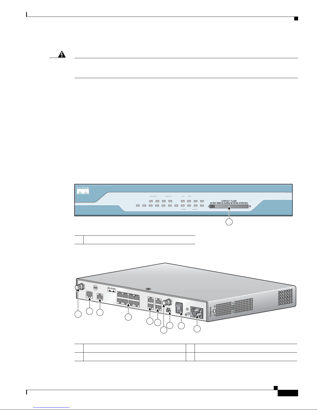
Figure 1-3 Front Panel of Cisco 1801 Router
Statement 1015
1 CompactFlash Slot
Figure 1-4 Back Panel of Cisco 1801 Router
1 ADSL over POTS WAN port 6 POE connector
2 ISDN BRI S/T port 7 Power switch
OL-6425-03
1
Cisco 1800 Series Integrated Services Routers (Fixed) Hardware Installation Guide
1-7
Page 24
Chassis Views
127447
SYS OK
POE
4 3
FEX
2
1 FE0
LINK
B1
ISDN
B2 CF
8
7 6
SWITCH
5
CO LPBK
PPP VPN
Cisco 1800
Series
DSL
1
127446
C
IS
C
O
1801
1
2
3
4
5
6
7
8
9
9
Chapter 1 Overview
3 Managed 8-port FE switch 8 Power connector
FE WAN port
4
5 Console and AUX ports
1. Inline power is a field-upgradable option only. It is not installed by default.
2. The Cisco 1801 only has one FE WAN port, which is the lower of the two ports shown. The upper port is disabled, and
reserved for a future purpose.
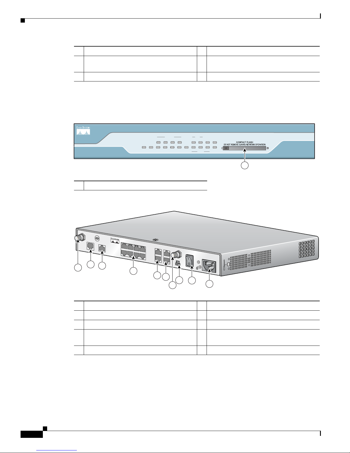
Figure 1-5 Front Panel of Cisco 1802 Router
2
RP-TNC antenna connectors (wireless models
only)
9
1 CompactFlash Slot
Figure 1-6 Back Panel of Cisco 1802 Router
1 ADSL over ISDN WAN port 6 POE connector
1
2 ISDN BRI S/T port 7 Power switch
3 Managed 8-port FE switch 8 Power connector
FE WAN port
4
2
RP-TNC antenna connectors (wireless models
only)
9
5 Console and AUX ports
1. Inline power is a field-upgradable option only. It is not installed by default.
2. The Cisco 1802 only has one FE WAN port, which is the lower of the two ports shown. The upper port is disabled, and
reserved for a future purpose.
1-8
Cisco 1800 Series Integrated Services Routers (Fixed) Hardware Installation Guide
OL-6425-03
Page 25

Chapter 1 Overview
127447
SYS OK
POE
4 3
FEX
2
1 FE0
LINK
B1
ISDN
B2 CF
8
7 6
SWITCH
5
CO LPBK
PPP VPN
Cisco 1800
Series
DSL
1
127446
C
IS
C
O
18
01
1
2
3
4
5
6
7
8
9
9
Chassis Views
Figure 1-7 Front Panel of Cisco 1803 Router
1 CompactFlash Slot
Figure 1-8 Back Panel of Cisco 1803 Router
1 G.SHDSL WAN port 6 POE connector
2 ISDN BRI S/T port 7 Power switch
3 Managed 8-port FE switch 8 Power connector
FE WAN port
4
5 Console and AUX ports
1. Inline power is a field-upgradable option only. It is not installed by default.
2. The Cisco 1803 only has one FE WAN port, which is the lower of the two ports shown. The upper port is disabled, and
reserved for a future purpose.
Cisco 1811 Chassis
Figure 1-9 shows the front panel of a Cisco 1811 router. Figure 1-10 shows the rear panel of a
Cisco 1811 router.
1
2
RP-TNC antenna connectors (wireless models
only)
9
OL-6425-03
Cisco 1800 Series Integrated Services Routers (Fixed) Hardware Installation Guide
1-9
Page 26

Chassis Views
SYS OK
POE
5 4
FEX
3
2
FE0
CD
SPD
V.92
BUSY CF
9
8 7
SWITCH
6
FE1
PPP VPN
Cisco 1800
Series
127448
1
127450
1
2
3
4
5
6
7
8
9
9
Chapter 1 Overview
Figure 1-9 Front Panel of Cisco 1811 Router
1 CompactFlash Slot
Figure 1-10 Back Panel of Cisco 1811 Router
1 V.92 Modem port 6 POE connector
2 USB 2.0 ports 7 Power switch
3 Managed 8-port FE switch 8 Power connector
FE WAN ports
4
5 Console and AUX ports
1. Inline power is a field-upgradable option only. It is not installed by default.
Cisco 1812 Chassis
Figure 1-11 shows the front panel of a Cisco 1812 router. Figure 1-12 shows the back panel of a
Cisco 1812 router.
1
RP-TNC antenna connectors (wireless models
only)
9
1-10
Cisco 1800 Series Integrated Services Routers (Fixed) Hardware Installation Guide
OL-6425-03
Page 27

Chapter 1 Overview
SYS OK
POE
S 4
FEX
3
2
FE0
LINK
B1
ISDN
B2 CF
9
8 7
SWITCH
6
FE1
PPP VPN
Cisco 1800
Series
127167
1
127161
1
2
3
4
5
6
7
8
9
9
Interface Numbering
Figure 1-11 Front Panel of Cisco 1812 Router
1 CompactFlash Slot
Figure 1-12 Back Panel of Cisco 1812 Router
1 ISDN BRI S/T port 6 POE connector
2 USB 2.0 ports 7 Power switch
3 Managed 8-port FE switch 8 Power connector
FE WAN ports
4
5 Console and AUX ports
1. Inline power is a field-upgradable option only. It is not installed by default.
Interface Numbering
The WAN and LAN interfaces on a Cisco 1800 series fixed-configuration router are numbered as
follows:
• On the Cisco 1811 and Cisco 1812 routers, the Fast Ethernet 10/100 WAN ports are numbered FE
0 and FE
• On the Cisco 1801, Cisco 1802, and Cisco 1803 routers, the Fast Ethernet 10/100 WAN port is
numbered FE 0.
• On the Cisco 1811 and Cisco 1812 routers, the Fast Ethernet LAN switch ports are numbered FE 2
through FE 9. The FE 2 port is the lower port, farthest on the right (as viewed from the rear of the
router), and switch ports are numbered incrementally, FE 2 through FE 5, to the left along the
bottom row, and then incrementally, FE
OL-6425-03
1; the lower of the two ports is FE 0.
1
RP-TNC antenna connectors (wireless models
only)
9
6 through FE 9, to the left along the top row.
Cisco 1800 Series Integrated Services Routers (Fixed) Hardware Installation Guide
1-11
Page 28

Specifications
• On the Cisco 1801, Cisco 1802, and Cisco 1803 routers, the Fast Ethernet LAN switch ports are
numbered FE 1 through FE 8. The FE 1 port is the lower port, farthest on the right (as viewed from
the rear of the router), and switch ports are numbered incrementally, FE 1 through FE 4, to the left
along the bottom row, and then incrementally, FE
• The ADSL over POTS, ADSL over ISDN, G.SHDSL, ISDN S/T, and V.92 modem WAN ports are
all numbered port 0 of their various type.
• On the Cisco 1811 and Cisco 1812 routers, the USB 2.0 ports are numbers usb 0 and usb 1. The
usb
Specifications
Table 1-5 provides the specifications for Cisco 1800 series fixed-configuration routers.
Ta b l e 1-5 Specifications for Cisco 1800 Series Fixed-Configuration Routers
Description Specification
Dimensions (W x D) 12.5 x 9.5 in. (31.75 x 24.13 cm)
Chapter 1 Overview
5 through FE 8, to the left along the top row.
0 port is the lower of the two ports and usb 1 is the upper port.
Height without rubber feet: 1.73 in. (4.39 cm)
Height with rubber feet: 1.87 in. (4.75 cm)
Weight Maximum: 6.1 lb (2.8 kg)
AC input power
Input voltage
Frequency
Input current
Inrush surge current
74 W maximum
100 to 240 VAC
50 or 60 Hz
1.2 to 0.6 A
50 A maximum, one cycle (–48V power included)
Power dissipation (maximum) 153 BTU/hr
Console and auxiliary ports RJ-45 connector
Operating humidity 10 to 85% noncondensing operating; 5 to 95% noncondensing,
nonoperating
Operating temperature 32 to 104° F (0 to 40° C)
Nonoperating temperature –4 to 149° F (–20 to 65° C)
Noise level <78° F/25.6°C: 34 dBA
>78°F/25.6°C through <104°F/40°C: 37 dBA
>104°F/40°C: 42 dBA
Safety compliance UL 60950; CAN/CSA C22.2 No. 60950; IEC 60950-1;
EN
60950-1; AS/NZS 60950
For detailed compliance information, see the Regulatory
Compliance and Safety Information for Cisco 1800 Integrated
Services Routers (Fixed) document.
Cisco 1800 Series Integrated Services Routers (Fixed) Hardware Installation Guide
1-12
OL-6425-03
Page 29

Chapter 1 Overview
Table 1-5 Specifications for Cisco 1800 Series Fixed-Configuration Routers (continued)
Description Specification
EMC Immunity compliance EN300386; EN55024(CISPR24); EN61000-4-2; EN61000-4-3;
EMC Emissions compliance CFR 47 Part 15, Class A; ICES-003 Class A; EN55022 Class A;
Regulatory Compliance
Regulatory Compliance
EN61000-4-4; EN61000-4-5; EN61000-4-6; EN61000-4-8;
EN61000-4-11; EN55082-1; EN61000-6-2; ITU-T K.21
For detailed compliance information, see the Regulatory
Compliance and Safety Information for Cisco 1800 Integrated
Services Routers (Fixed) document.
CISPR22 Class A; AS/NZS 3548 Class A; VCCI Class A;
EN
300386; EN61000-3-2; EN61000-3-3
For detailed compliance information, see the Regulatory
Compliance and Safety Information for Cisco 1800 Integrated
Services Routers (Fixed) document.
For compliance information, see the Regulatory Compliance and Safety Information for Cisco 1800
Integrated Services Routers (Fixed) document that accompanied the router shipment.
OL-6425-03
Cisco 1800 Series Integrated Services Routers (Fixed) Hardware Installation Guide
1-13
Page 30

Regulatory Compliance
Chapter 1 Overview
Cisco 1800 Series Integrated Services Routers (Fixed) Hardware Installation Guide
1-14
OL-6425-03
Page 31

CHA PTER
2
Preinstallation Requirements
This chapter describes the site requirements and equipment necessary for installing your Cisco 1800
series fixed-configuration integrated services router. This chapter includes the following sections:
• Safety Recommendations, page 2-2
• General Site Requirements, page 2-4
• Installation Checklist, page 2-5
• Creating a Site Log, page 2-6
• Inspecting the Router, page 2-7
• Required Tools and Equipment for Installation and Maintenance, page 2-7
Note To see translations of the warnings that appear in this publication, see the Regulatory Compliance and
Safety Information for Cisco 1800 Integrated Services Routers (Fixed) document and for wireless
routers, the Declarations of Conformity and Regulatory Information for Cisco Access Products with
802.11a/b/g and 802.11b/g Radios document that accompany your router.
OL-6425-03
Warning
Warning
Warning
Warning
Only trained and qualified personnel should be allowed to install, replace, or service this equipment.
Statement 1030
Ultimate disposal of this product should be handled according to all national laws and regulations.
Statement 1040
Before opening the unit, disconnect the telephone-network cables to avoid contact with
telephone-network voltages.
This equipment must be installed and maintained by service personnel as defined by AS/NZS 3260.
Incorrectly connecting this equipment to a general-purpose outlet could be hazardous. The
telecommunications lines must be disconnected 1) before unplugging the main power connector or 2)
while the housing is open, or both.
Statement 1041
Statement 1043
Cisco 1800 Series Integrated Services Routers (Fixed) Hardware Installation Guide
2-1
Page 32

Safety Recommendations
Safety Recommendations
Follow these guidelines to ensure general safety:
• Keep the chassis area clear and dust-free during and after installation.
• If you remove the chassis cover, put it in a safe place.
• Keep tools and chassis components away from walk areas.
• Do not wear loose clothing that could get caught in the chassis. Fasten your tie or scarf and roll up
your sleeves.
• Wear safety glasses when working in conditions that might be hazardous to your eyes.
• Do not perform any action that creates a hazard to people or makes the equipment unsafe.
Safety with Electricity
Chapter 2 Preinstallation Requirements
Warning
Warning
Warning
This unit might have more than one power supply connection. All connections must be removed to
de-energize the unit.
Do not work on the system or connect or disconnect cables during periods of lightning activity.
Statement 1001
Read the installation instructions before connecting the system to the power source.
Statement 1028
Statement 1004
Follow these guidelines when working on equipment powered by electricity:
• Locate the emergency power-off switch in the room in which you are working. Then, if an electrical
accident occurs, you can quickly turn off the power.
• Disconnect all power before doing the following:
–
Installing or removing a chassis
–
Working near power supplies
• Look carefully for possible hazards in your work area, such as moist floors, ungrounded power
extension cables, frayed power cords, and missing safety grounds.
• Do not work alone if hazardous conditions exist.
• Never assume that power is disconnected from a circuit. Always check.
• Never open the enclosure of the router’s internal power supply.
• If an electrical accident occurs, proceed as follows:
–
Use caution; do not become a victim yourself.
–
Turn off power to the device.
–
If possible, send another person to get medical aid. Otherwise, assess the victim’s condition and
then call for help.
–
Determine if the person needs rescue breathing or external cardiac compressions; then take
appropriate action.
Cisco 1800 Series Integrated Services Routers (Fixed) Hardware Installation Guide
2-2
OL-6425-03
Page 33

Chapter 2 Preinstallation Requirements
In addition, use the following guidelines when working with any equipment that is disconnected from a
power source, but still connected to telephone wiring or other network cabling:
• Never install telephone wiring during a lightning storm.
• Never install telephone jacks in wet locations unless the jack is specifically designed for it.
• Never touch uninsulated telephone wires or terminals unless the telephone line is disconnected at
the network interface.
• Use caution when installing or modifying telephone lines.
Preventing Electrostatic Discharge Damage
Electrostatic discharge (ESD) can damage equipment and impair electrical circuitry. ESD can occur if
electronic printed circuit cards are improperly handled, and can cause complete or intermittent failures.
Always follow ESD prevention procedures when removing and replacing modules:
• Ensure that the router chassis is electrically connected to earth ground.
• Wear an ESD-preventive wrist strap, ensuring that it makes good skin contact. Connect the clip to
an unpainted surface of the chassis frame to channel unwanted ESD voltages safely to ground. To
guard against ESD damage and shocks, the wrist strap and cord must operate effectively.
• If no wrist strap is available, ground yourself by touching a metal part of the chassis.
Safety Recommendations
Caution For the safety of your equipment, periodically check the resistance value of the antistatic strap. It should
be between 1 and 10 megohms (Mohm).
Additional Warnings for Wireless Routers
Warning
Warning
In order to comply with FCC radio frequency (RF) exposure limits, antennas should be located at a
minimum of 7.9 inches (20 cm) or more from the body of all persons.
Do not operate your wireless network device near unshielded blasting
environment unless the device has been modified to be especially qualified for such use.
Statement 245B
General Safety Guidelines for Wireless Routers
The following are guidelines for the wireless router models:
• Do not touch or move antenna(s) while the unit is transmitting or receiving.
• Do not hold any component containing a radio so that the antenna is very close to or touching any
exposed parts of the body, especially the face or eyes, while transmitting.
Statement 332
caps or in an explosive
• The use of wireless devices in hazardous locations is limited to the constraints posed by the local
codes, the national codes, and the safety directors of such environments.
OL-6425-03
Cisco 1800 Series Integrated Services Routers (Fixed) Hardware Installation Guide
2-3
Page 34

General Site Requirements
General Site Requirements
This section describes the requirements your site must meet for safe installation and operation of your
router. Ensure that the site is properly prepared before you begin the installation. If you experience
shutdowns or unusually high error rates with your existing equipment, the information in this section
can help you isolate the cause of failures and prevent future problems.
Power Supply Considerations
Check the power at your site to ensure that you are receiving “clean” power (free of spikes and noise).
Install a power conditioner if necessary.
Chapter 2 Preinstallation Requirements
Warning
The device is designed for connection to TN and IT power systems.
The AC power supply includes a 6-foot (1.8-meter) electrical power cord. (A label near the power inlet
indicates the correct voltage, frequency [AC-powered systems only], current draw, and power
dissipation for the unit.)
Table 2-1 lists power requirements for the Cisco 1800 series fixed-configuration routers.
Ta b l e 2-1 Power Requirements for Cisco 1800 Series Fixed-Configuration Routers
Router Input Power
Without inline power support 100–120V/200–240V, 1.2A/0.6A 90 to 264 VAC
With inline power support 100–120V/200–240V, 1.2A/0.6A 90 to 264 VAC
Site Environment
The Cisco 1800 series fixed-configuration router can be placed on a desktop, installed in a rack, or
mounted on a wall or other vertical surface. The location of your router and the layout of your equipment
rack or wiring room are extremely important considerations for proper operation. Having equipment
placed too close together, inadequate ventilation, and inaccessible panels can cause malfunctions and
shutdowns, and can make maintenance difficult. Plan for access to both the front panel and the back
panel of the router. When facing the router front-bezel, airflow is from left to right,
Statement 1007
Input Voltage
Tolerance Limits
When you plan your site layout and equipment locations, keep in mind the precautions listed in the “Site
Configuration” section on page 2-5 to help prevent equipment failures and reduce the possibility of
environmentally caused shutdowns. If you are experiencing shutdowns or an unusually high number of
errors with your existing equipment, these precautions may help you isolate the cause of the failures and
prevent future problems.
Wireless LAN Considerations
The type of antenna used with your wireless router and its location greatly impact the quality of wireless
connections to the router. Cisco
different antenna types—swivel-mount dipole antennas that mounts on the back panel of the router, a
wall-mount antenna, and a ceiling-mount antenna.
Cisco 1800 Series Integrated Services Routers (Fixed) Hardware Installation Guide
2-4
1800 series fixed-configuration routers are compatible with three
OL-6425-03
Page 35

Chapter 2 Preinstallation Requirements
For more information about antenna coverage and optimal usage, see the following documents:
• Cisco Multiband Swivel-Mount Dipole Antenna
• Cisco Multiband Diversity Omnidirectional Ceiling-Mount Antenna
• Cisco Multiband Wall-Mount, Corner-Mount, or Mast-Mount Antenna
Site Configuration
The following precautions will help you plan an acceptable operating environment for your router and
will help you avoid environmentally caused equipment failures:
• Ensure adequate air circulation in the room where your router operates. Electrical equipment
generates heat. Without adequate air circulation, ambient air temperature may not cool equipment
to acceptable operating temperatures.
• To avoid damaging equipment, always follow the ESD-prevention procedures described in the
“Preventing Electrostatic Discharge Damage” section on page 2-3. Damage from static discharge
can cause immediate or intermittent equipment failure.
• Ensure that the chassis cover and module back panels are secure. All empty network module slots,
interface card slots, and power supply bays must have filler panels installed. The chassis is designed
to allow cooling air to flow within it through specially designed cooling slots. A chassis with
uncovered openings permits air leaks, which may interrupt and reduce the flow of air across internal
components.
Installation Checklist
Installation Checklist
The sample installation checklist lists items and procedures for installing a new router. Make a copy of
this checklist and record the information in each column as you complete each task. Include a copy of
the checklist for each router in your Site Log (described in the
page 2-6).
Installation Checklist for Site_____________________________________________
Router Name_______________________________________________________
Tas k Verified by Date
Installation Checklist copied
Background information placed in Site Log
Site power voltages verified
Installation site power check completed
Required tools available
Additional equipment available
Router received
Router quick start guide received
“Creating a Site Log” section on
OL-6425-03
Cisco 1800 Series Integrated Services Routers (Fixed) Hardware Installation Guide
2-5
Page 36

Creating a Site Log
Chapter 2 Preinstallation Requirements
Installation Checklist for Site_____________________________________________
Router Name_______________________________________________________
Task Verified by Date
Regulatory Compliance and Safety Information for Cisco
1800 Integrated Services Routers (Fixed) document
received
Declarations of Conformity and Regulatory Information
for Cisco Access Products with 802.11a/b/g and 802.11b/g
Radios document received (wireless routers only)
Product registration card received
Cisco.com contact information label received
Chassis components verified
Initial electrical connections established
ASCII terminal (for local configuration) or
modem
Signal distance limits verified
Startup sequence steps completed
Initial operation verified
Software image verified
(for remote configuration) available
Creating a Site Log
Use a Site Log to keep a record of all actions related to the router. Keep it in an accessible place near
the chassis so that anyone who performs tasks has access to it. Use the Installation Checklist to verify
steps in the installation and maintenance of the router. Site Log entries might include the following
information:
• Installation progress—Make a copy of the Installation Checklist and insert it into the Site Log.
Record information as each procedure is completed.
• Upgrade and maintenance procedures—Use the Site Log as a record of ongoing router maintenance
and expansion. A Site Log might include the following events:
–
Installation of network modules
–
Removal or replacement of network modules and other upgrades
–
Configuration changes
–
Maintenance schedules and requirements
–
Performance of maintenance procedures
–
Observations of intermittent problems
–
Comments and notes
Cisco 1800 Series Integrated Services Routers (Fixed) Hardware Installation Guide
2-6
OL-6425-03
Page 37

Chapter 2 Preinstallation Requirements
Inspecting the Router
Do not unpack the router until you are ready to install it. If the final installation site will not be ready
for some time, keep the chassis in its shipping container to prevent accidental damage. Unpack the router
only when you are ready to install it.
The router, cables, publications, and any optional equipment that you ordered may be shipped in more
than one container. When you unpack the containers, check the packing list to ensure that you received
all the following items:
• Router
• 6-foot (1.8-meter) power cord
• Cable management bracket
• RJ-45-to-DB-9 console cable
• DB-9-to-DB-25 connector adapter
• Two swivel-mount dipole antennas (wireless models only)
• Optional equipment (such as network connection cables or rack-mount brackets)
Inspecting the Router
• Cabling and installation document
• Regulatory Compliance and Safety Information for Cisco 1800 Integrated Services Routers (Fixed)
document
• (Wireless routers only) Declarations of Conformity and Regulatory Information for Cisco Access
Products with 802.11a/b/g and 802.11b/g Radios document
• Cisco Router and Security Device Manager (SDM) Quick Start Guide
• Product Registration card and Cisco.com card
Inspect all items for shipping damage. If anything appears to be damaged, or if you have problems
installing or configuring your router, contact customer service. Warranty, service, and support
information is given in the cabling and installation document that shipped with your router.
Required Tools and Equipment for Installation and Maintenance
You need the following tools and equipment to install and upgrade the router and its components:
• ESD-preventive cord and wrist strap
• Number-2 Phillips screwdriver
• Flat-blade screwdriver to remove the cover, if you are upgrading memory or other components
• Screws that fit your rack
• Wire crimper
• Wire for connecting the chassis to an earth ground:
–
AWG 14 (2 mm2) or larger wire for NEC-compliant chassis grounding
–
AWG 18 (1 mm2) or larger wire for EN/IEC 60950–compliant chassis grounding
• For NEC-compliant grounding, an appropriate user-supplied ring terminal, with an inner diameter
of 1/4 inch (5 to 7 millimeters)
In addition, depending on your planned network configuration, you might need the following equipment
to connect a port to an external network:
OL-6425-03
Cisco 1800 Series Integrated Services Routers (Fixed) Hardware Installation Guide
2-7
Page 38

Required Tools and Equipment for Installation and Maintenance
• Ethernet cables for connection to the Fast Ethernet WAN and LAN ports
Note For more information on cable specifications, see the online document Cisco Modular
Access Router Cable Specifications on Cisco.com.
• Ethernet hub or PC with a network interface card for connection to a Fast Ethernet (LAN) port
• Console terminal (an ASCII terminal or a PC that is running HyperTerminal or similar terminal
emulation software) configured for 9600 baud, 8 data bits, 1 stop bit, no flow control, and no parity
• Modem for connection to the auxiliary port for remote administrative access (optional)
• NT1 device for ISDN BRI S/T interfaces (if this device was not supplied by your service provider)
• Wall-mount or ceiling-mount antennas for wireless routers (if you do not intend to use the supplied
dipole antennas)
Chapter 2 Preinstallation Requirements
Cisco 1800 Series Integrated Services Routers (Fixed) Hardware Installation Guide
2-8
OL-6425-03
Page 39

CHA PTER
3
Chassis Installation Procedures
This chapter describes how to install your Cisco 1800 series fixed-configuration router on a desktop or
on a wall. It includes the following sections:
• Setting Up the Chassis, page 3-1
• Installing the Chassis Ground Connection, page 3-3
Note To see translations of the warnings that appear in this publication, see the Regulatory Compliance and
Safety Information for Cisco 1800 Integrated Services Routers (Fixed) document that accompanied this
device.
Warning
Only trained and qualified personnel should be allowed to install, replace, or service this equipment.
Statement 1030
Warning
This unit is intended for installation in restricted access areas. A restricted access area can be
accessed only through the use of a special tool, lock and key, or other means of security.
Statement 1017
Setting Up the Chassis
Warning
Before working on a system that has an on/off switch, turn OFF the power and unplug the power cord.
Statement 1
You can set a Cisco 1800 series fixed-configuration router on a desktop or mount it on a wall. See the
applicable instructions in the following sections.
• Setting a Cisco 1800 Series Fixed-Configuration Router on a Desktop
• Chassis Grounding
• Mounting a Cisco 1800 Series Fixed-Configuration Router on a Wall
OL-6425-03
Cisco 1800 Series Integrated Services Routers (Fixed) Hardware Installation Guide
3-1
Page 40

Chapter 3 Chassis Installation Procedures
Setting Up the Chassis
Caution To prevent damage to the chassis, never attempt to lift or tilt the chassis by holding the plastic panel on
the front. Always hold the chassis by the metal body.
Setting a Cisco 1800 Series Fixed-Configuration Router on a Desktop
You can place Cisco 1800 series fixed-configuration routers on a desktop or shelf. Do not place anything
on top of the router that weighs more than 10 pounds (4.5
desktop. Excessive weight on top of the router could damage the chassis.
Caution Your chassis installation must allow unrestricted airflow for chassis cooling. When placing the router
on a desktop, keep at least 1 inch (2.5 cm) of clear space beside the cooling inlet and exhaust vents.
After the router is installed, you must connect the chassis to a reliable earth ground. For the chassis
ground connection procedures, see the
“Installing the Chassis Ground Connection” section on page 3-3.
kilograms), and do not stack routers on a
Chassis Grounding
After you install the router, you must connect the chassis to a reliable earth ground. For the chassis
ground connection procedures, see the
“Installing the Chassis Ground Connection” section on page 3-3.
Mounting a Cisco 1800 Series Fixed-Configuration Router on a Wall
The Cisco 1800 series fixed-configuration routers have slots on the bottom of the chassis for mounting
the unit on a wall or other vertical surface.
Warning
Tip When choosing a location for wall-mounting the router, consider cable limitations and wall structure.
Tip If your router has the optional wireless LAN feature, before you mount the router on a wall, connect the
This unit is intended to be mounted on a wall. Please read the wall mounting instructions carefully
before beginning installation. Failure to use the correct hardware or to follow the correct procedures
could result in a hazardous situation to people and damage to the system.
antennas to the back panel. It is difficult to attach the antennas after the router has been mounted to a
wall.
Statement 248
To attach the router to a wall, use the following hardware:
• For attaching to a wall stud, use two number-10 wood screws (round- or pan-head) with number-10
washers, or two number-10 washer-head screws. The screws must be long enough to penetrate at
least 3/4 inch (20 millimeters) into the supporting wood or metal wall stud.
• For hollow-wall mounting, use two number-10 wall anchors with washers.
Cisco 1800 Series Integrated Services Routers (Fixed) Hardware Installation Guide
3-2
OL-6425-03
Page 41

Chapter 3 Chassis Installation Procedures
1
Figure 3-1 shows the underside of a Cisco 1800 series fixed-configuration router and the locations of the
wall-mount holes.
Figure 3-1 Mount Holes on Underside of Cisco 1800 Series Fixed-Configuration Router Chassis
Installing the Chassis Ground Connection
1 Holes for wall-mounting
After you install the router, you must connect the chassis to a reliable earth ground. For the chassis
ground connection procedures, see the
“Installing the Chassis Ground Connection” section on page 3-3.
Installing the Chassis Ground Connection
Warning
This equipment must be grounded. Never defeat the ground conductor or operate the equipment in the
absence of a suitably installed ground conductor. Contact the appropriate electrical inspection
authority or an electrician if you are uncertain that suitable grounding is available.
You must connect the chassis to a reliable earth ground; the ground wire must be installed in accordance
with local electrical safety standards.
• For NEC-compliant grounding, use size 14 AWG (2 mm
user-supplied ring terminal with an inner diameter of 1/4 inch (5 to 7 millimeters).
• For EN/IEC 60950–compliant grounding, use size 18 AWG (1 mm
appropriate user-supplied ring terminal.
Follow these steps to install the ground connection:
Statement 1024
2
) or larger copper wire and an appropriate
2
) or larger copper wire and an
OL-6425-03
Cisco 1800 Series Integrated Services Routers (Fixed) Hardware Installation Guide
3-3
Page 42

Installing the Chassis Ground Connection
Step 1 Strip one end of the ground wire to the length required for the ground lug or terminal.
Step 2 Crimp the ground wire to the ground lug or ring terminal, using a wire crimper of the appropriate size.
Step 3 Attach the ground lug or ring terminal to the chassis. For a ground lug, use the provided two screws with
captive locking washers. For a ring terminal, use one of the screws provided. Tighten the screws to a
torque of 8 to 10 in-lb (0.9
Note To see an illustration of this procedure, go to the following URL:
http://www.cisco.com/en/US/docs/routers/access/1800/1841/hardware/quick/guide/1800qsg.html
Step 4 Connect the other end of the ground wire to a known reliable earth ground point at your site.
After you install and properly ground the router, you can connect the power wiring, the WAN and LAN
cables, and the cables for administrative access as required for your installation. For information about
connecting the cables, see Chapter 4, “
Chapter 3 Chassis Installation Procedures
to 1.1 N-m).
Power, Cable, and Antenna Connection Procedures.”
Cisco 1800 Series Integrated Services Routers (Fixed) Hardware Installation Guide
3-4
OL-6425-03
Page 43

CHA PTER
4
Power, Cable, and Antenna Connection
Procedures
This chapter describes how to connect your Cisco 1800 series fixed-configuration router to a power
source and to networks and external devices. It includes the following sections:
• Power Connections, page 4-1
• Connecting WAN and LAN Cables, page 4-2
• Connecting to a Console Terminal or Modem, page 4-5
• Connecting the Radio Antennas to the Wireless Router, page 4-8
Note To see translations of the warnings that appear in this publication, see the Regulatory Compliance and
Safety Information for Cisco 1800 Integrated Services Routers (Fixed) document and for wireless
routers, the Declarations of Conformity and Regulatory Information for Cisco Access Products with
802.11a/b/g and 802.11b/g Radios document that accompany your router.
Warning
Warning
Only trained and qualified personnel should be allowed to install, replace, or service this equipment.
Statement 1030
Do not work on the system or connect or disconnect cables during periods of lightning activity.
Statement 1001
Power Connections
This section explains how to connect AC power to a Cisco 1800 series fixed-configuration router. It
covers the following topics:
• Connecting Routers to AC Power, page 4-2
• Connecting WAN and LAN Cables, page 4-2
Warning
OL-6425-03
Read the installation instructions before connecting the system to the power source.
Statement 1004
Cisco 1800 Series Integrated Services Routers (Fixed) Hardware Installation Guide
4-1
Page 44

Connecting WAN and LAN Cables
Note The installation must comply with all required electrical codes applicable at the installation site.
Connecting Routers to AC Power
Connect your router to a 15A, 120-VAC (10A, 240-VAC) circuit with overcurrent protection.
Note The input voltage tolerance limits for AC power are 90 and 264 VAC.
Chapter 4 Power, Cable, and Antenna Connection Procedures
Warning
Warning
Warning
Warning
Warning
This product relies on the building’s installation for short-circuit (overcurrent) protection. Ensure that
the protective device is rated not greater than:
15A, 120VAC (10A, 240VAC).
This equipment has been designed for connection to TN and IT power systems.
This equipment must be grounded. Never defeat the ground conductor or operate the equipment in the
absence of a suitably installed ground conductor. Contact the appropriate electrical inspection
authority or an electrician if you are uncertain that suitable grounding is available.
This equipment must be installed and maintained by service personnel as defined by AS/NZS 3260.
Incorrectly connecting this equipment to a general-purpose outlet could be hazardous. The
telecommunications lines must be disconnected 1) before unplugging the main power connector or 2)
while the housing is open, or both.
When installing or replacing the unit, the ground connection must always be made first and
disconnected last.
Statement 1046
Statement 1005
Statement 1043
Statement 1007
Statement 1024
Connecting WAN and LAN Cables
This section describes how to connect the WAN, LAN, and voice interface cables. It covers the
following topics:
• Preparing to Connect to a Network, page 4-3
• Ports and Cabling, page 4-4
• Connection Procedures and Precautions, page 4-5
Note Ethernet cables and transceivers can be ordered from Cisco Systems. For ordering information, contact
customer service. For cable pinouts, refer to the
document.
Cisco 1800 Series Integrated Services Routers (Fixed) Hardware Installation Guide
4-2
Cisco Modular Access Router Cable Specifications
OL-6425-03
Page 45

Chapter 4 Power, Cable, and Antenna Connection Procedures
Connecting WAN and LAN Cables
Warning
Warning
Warning
Warning
Warning
To avoid electric shock, do not connect safety extra-low voltage (SELV) circuits to telephone-network
voltage (TNV) circuits. LAN ports contain SELV circuits, and WAN ports contain TNV circuits. Some
LAN and WAN ports both use RJ-45 connectors. Use caution when connecting cables.
Statement 1021
Hazardous network voltages are present in WAN ports regardless of whether power to the unit is OFF
or ON. To avoid electric shock, use caution when working near WAN ports. When detaching cables,
detach the end away from the unit first.
Statement 1026
Do not use this product near water; for example, near a bath tub, wash bowl, kitchen sink or laundry
tub, in a wet basement, or near a swimming pool.
Statement 1035
Never install telephone jacks in wet locations unless the jack is specifically designed for
wet locations.
Statement 1036
Never touch uninsulated telephone wires or terminals unless the telephone line has been
disconnected at the network interface.
Statement 1037
Warning
Warning
Warning
To report a gas leak, do not use a telephone in the vicinity of the leak.
Before opening the unit, disconnect the telephone-network cables to avoid contact with
telephone-network voltages.
Statement 1041
This equipment must be installed and maintained by service personnel as defined by AS/NZS 3260.
Incorrectly connecting this equipment to a general-purpose outlet could be hazardous. The
telecommunications lines must be disconnected 1) before unplugging the main power connector or 2)
while the housing is open, or both.
Preparing to Connect to a Network
When setting up your router, consider distance limitations and potential electromagnetic interference
(EMI) as defined by the applicable local and international regulations.
See the network connection considerations for the following network interfaces:
• Ethernet Connections
• ISDN BRI Connections
See the following online documents for more information about network connections and interfaces:
• Cisco Interface Cards Hardware Installation Guide
Statement 1039
Statement 1043
• Cisco Modular Access Router Cable Specifications
OL-6425-03
Cisco 1800 Series Integrated Services Routers (Fixed) Hardware Installation Guide
4-3
Page 46

Connecting WAN and LAN Cables
Ethernet Connections
The IEEE has established Ethernet as standard IEEE 802.3. The Cisco 1800 series fixed-configuration
routers support the following Ethernet implementations:
• 100BASE-T—100-Mbps full-duplex transmission over a Category 5 or better unshielded
• 10BASE-T—10-Mbps full-duplex transmission over a Category 5 or better unshielded twisted-pair
See the Cisco Modular Access Router Cable Specifications online document for information about
Ethernet cables, connectors, and pinouts.
ISDN BRI Connections
The ISDN BRI S/T interface on the Cisco 1801, Cisco 1802, Cisco 1803 and Cisco 1812 routers provides
an ISDN BRI connection for dial-backup purposes. The BRI S/T interface requires an external Network
Terminator 1 (NT1).
Use a BRI cable (not included) to connect the BRI S/T interface card directly to an ISDN NT1. Table 4-1
lists the specifications for ISDN BRI cables. Also, see the Cisco Modular Access Router Cable
Specifications online document for pinouts. This document is located on Cisco.com.
Chapter 4 Power, Cable, and Antenna Connection Procedures
twisted-pair (UTP) cable. Supports the Ethernet maximum length of 328
(UTP) cable. Supports the Ethernet maximum length of 328
feet (100 meters).
feet (100 meters).
Ta b l e 4-1 ISDN BRI Cable Specifications
Specification High-Capacitance Cable Low-Capacitance Cable
Resistance (at 96 kHz) 160 ohm/km 160 ohm/km
Capacitance (at 1 kHz) 120 nF1/km
Impedance (at 96 kHz) 75 ohm 150 ohm
Wire diameter 0.024 in. (0.6 mm) 0.024 in. (0.6 mm)
Distance limitation 32.8 ft (10 m) 32.8 ft (10 m)
1. nF = nanofarad
Ports and Cabling
Table 4-2 summarizes WAN and LAN connections for Cisco 1800 series fixed-configuration routers.
The connections summarized in Ta ble 4-2 are also described in detail in the following documents:
• Cisco Modular Access Router Cable Specifications
• Cisco Network Modules Hardware Installation Guide
• Cisco Interface Cards Hardware Installation Guide
30 nF/km
Cisco 1800 Series Integrated Services Routers (Fixed) Hardware Installation Guide
4-4
OL-6425-03
Page 47

Chapter 4 Power, Cable, and Antenna Connection Procedures
Ta b l e 4-2 WAN and LAN Connections
Connecting to a Console Terminal or Modem
Port or Connection Port Type, Color
Ethernet
2
RJ-45, yellow Ethernet hub, Ethernet switch, or
1
Connection Device Cable
Category 5 or higher Ethernet
Ethernet network interface
card
(NIC)
ADSL RJ-11C/CA11A,
lavender
SHDSL RJ-11C/CA11A,
lavender, RJ-14
BRI S/T WAN
RJ-45/CB-1D, orange NT1 device or private integrated
(external NT1)
Network demarcation device for
service provider DSL interface
Network demarcation device for
service provider DSL interface
services network exchange (PINX)
RJ-11 straight-through
RJ-11 straight-through for 2-wire
RJ-14 straight-through for 4-wire
RJ-45 straight-through
Analog Modem RJ-11 PSTN RJ-11 straight-through
1. Cable color codes are specific to Cisco cables.
2. Ethernet connection information applies to both WAN ports and Ethernet LAN switch ports.
Connection Procedures and Precautions
Follow these steps to connect your router to the network:
Step 1 Confirm that the router is powered off.
Step 2 Connect each WAN or LAN cable to the appropriate connector on the chassis. For locations of the
chassis WAN and LAN ports, see the
“Chassis Views” section on page 1-7.
• Position the cables carefully, so that they do not put strain on the connectors.
• Bundle the cables so that they do not intertwine.
• Inspect the cables to make sure that the routing and bend radiuses are satisfactory. Reposition
cables, if necessary.
• Install cable ties in accordance with site requirements.
Step 3 Connect the other end of each WAN or LAN cable to the appropriate network device. See Ta b le 4-2 for
information about which network devices to connect each cable to.
Note For cable pinouts, see the Cisco Modular Access Router Cable Specifications document.
Connecting to a Console Terminal or Modem
Your router has asynchronous serial console and auxiliary ports for system management. These ports
provide administrative access to your router either locally (with a console terminal or PC) or remotely
(with a modem).
Cisco Systems provides the following cables for connecting your router to a console terminal, PC, or
modem:
OL-6425-03
Cisco 1800 Series Integrated Services Routers (Fixed) Hardware Installation Guide
4-5
Page 48

Chapter 4 Power, Cable, and Antenna Connection Procedures
Connecting to a Console Terminal or Modem
• One console cable (RJ-45-to-DB-9, blue)
• One DB-9-to-DB-25 adapter
This section describes how to connect a console terminal or PC to the console port and how to connect
a modem to the auxiliary port.
Ta b l e 4-3 System Management Connections
Port Color Connected Device Cable
Console Light blue PC or ASCII terminal communication port
(usually labeled COM)
Auxiliary Black Modem for remote access RJ-45-to-DB-9 console cable with a
For information about cable pinouts, see the Cisco Modular Access Router Cable Specifications
document.
Table 4-3 summarizes the system management connections.
RJ-45-to-DB-9 console cable
DB-9-to-DB25 adapter
Warning
Warning
Warning
To avoid electric shock, do not connect safety extra-low voltage (SELV) circuits to telephone-network
voltage (TNV) circuits. LAN ports contain SELV circuits, and WAN ports contain TNV circuits. Some
LAN and WAN ports both use RJ-45 connectors. Use caution when connecting cables.
Hazardous network voltages are present in WAN ports regardless of whether power to the unit is OFF
or ON. To avoid electric shock, use caution when working near WAN ports. When detaching cables,
detach the end away from the unit first.
Before opening the unit, disconnect the telephone-network cables to avoid contact with
telephone-network voltages.
Statement 1041
Statement 1026
Console and Auxiliary Port Considerations
The router includes an asynchronous serial console port and an auxiliary port. The console and auxiliary
ports provide access to the router either locally (using a console terminal connected to the console port)
or remotely (using a modem connected to the auxiliary port). This section provides important
information about cabling that you should consider before you connect the router to a console terminal
or a modem.
The main difference between the console port and the auxiliary port is that the auxiliary port supports
hardware flow control and the console port does not. Flow control paces the transmission of data
between a sending device and a receiving device. Flow control ensures that the receiving device can
absorb the data sent to it before the sending device sends more. When the buffers on the receiving device
are full, a message is sent to the sending device to suspend transmission until the data in the buffers has
been processed. Because the auxiliary port supports flow control, it is ideally suited for use with the
high-speed transmissions of a modem. Because console terminals send data at slower speeds than
modems, the console port is ideally suited for use with console terminals.
Statement 1021
Cisco 1800 Series Integrated Services Routers (Fixed) Hardware Installation Guide
4-6
OL-6425-03
Page 49

Chapter 4 Power, Cable, and Antenna Connection Procedures
Console Port Connections
The router has an EIA/TIA-232 asynchronous serial console port (RJ-45). Depending on the cable and
the adapter used, this port will appear as a DTE or DCE device at the end of the cable.
Your router is supplied with an RJ-45-to-DB-9 adapter cable for connecting to a PC that is running
terminal emulation software.
To connect the router to an ASCII terminal, use the RJ-45-to-DB-9 cable and a DB-9-to-DB-25 adapter.
The default parameters for the console port are 9600 baud, 8 data bits, 1 stop bit, and no parity. The
console port does not support hardware flow control. For detailed information about installing a console
terminal, see the
“Connecting to a Console Terminal or Modem” section on page 4-5.
For cable and port pinouts, see the online document Cisco Modular Access Router Cable Specifications.
This document is located on Cisco.com.
Connecting to the Console Port
If a console terminal or PC is connected to the console port, you can configure the router locally. Follow
these steps to connect a console terminal or PC that is running HyperTerminal or similar terminal
emulation software to the console port on the router:
Connecting to a Console Terminal or Modem
Step 1 Use the blue RJ-45-to-DB-9 console cable to connect the router to a terminal.
Note On the Cisco 1800 series fixed-configuration routers, the console port is color-coded blue.
Step 2 Configure your terminal or terminal emulation software for 9600 baud (default), 8 data bits, 1 stop bit,
and no parity; set flow control to “none.”
Note Because hardware flow control is not supported on the console port, do not connect modems to
the console port. Connect modems only to the auxiliary port.
Auxiliary Port Connections
The router has an EIA/TIA-232 asynchronous serial auxiliary port (RJ-45) that supports flow control.
Depending on the cable and the adapter used, this port appears as a DTE or DCE device at the end of the
cable.
Your router is supplied with a DB-9-to-DB-25 adapter for connecting to a modem.
For detailed information about connecting devices to the auxiliary port, see the “Connecting to a Console
Terminal or Modem” section on page 4-5.
For cable and port pinouts, see the Cisco Modular Access Router Cable Specifications online document
on Cisco.com.
OL-6425-03
Cisco 1800 Series Integrated Services Routers (Fixed) Hardware Installation Guide
4-7
Page 50

Chapter 4 Power, Cable, and Antenna Connection Procedures
Connecting the Radio Antennas to the Wireless Router
Connecting to the Auxiliary Port
If a modem is connected to the auxiliary port, a remote user can dial in to the router and configure it.
Follow these steps to connect a modem to the auxiliary port on the router:
Step 1 Use the black RJ-45-to-DB-25 modem cable or the RJ-45-to-DB-9 console cable with a DB-9 to DB-25
adapter to connect the router to a modem.
Step 2 Make sure that your modem and the router auxiliary port are configured for the same transmission speed
(up to 115,200 bps is supported) and hardware flow control with data carrier detect (DCD) and data
terminal ready (DTR) operations.
Connecting the Radio Antennas to the Wireless Router
If your router has the wireless LAN option, connect the antennas by screwing the antenna connectors in
a clockwise direction onto the reverse-polarity threaded Neill-Concelman (RP-TNC) connectors on the
back panel of the router.
antennas to the router.
Figure 4-1 shows an example of how to connect the swivel-mount dipole
Note For more information about the antennas compatible with the Cisco 1800 series fixed-configuration
routers, see the “Supported Cisco Radio Antennas (Wireless Models Only)” section.
Figure 4-1 Connecting Swivel-Mount Dipole Antennas to the Router RP-TNC Connectors
After you have attached the antennas, you must orient them. For best radio performance, the dipole
antennas are usually oriented so that they are perpendicular to the ground.
orientation for a router that is mounted in a rack or placed on a horizontal surface. A wall-mounted router
would typically have the dipole antennas pointing straight up or straight down.
Figure 4-2 shows this
Cisco 1800 Series Integrated Services Routers (Fixed) Hardware Installation Guide
4-8
OL-6425-03
Page 51

Chapter 4 Power, Cable, and Antenna Connection Procedures
127911
Figure 4-2 Dipole Antenna Orientation
Connecting the Radio Antennas to the Wireless Router
OL-6425-03
Cisco 1800 Series Integrated Services Routers (Fixed) Hardware Installation Guide
4-9
Page 52

Connecting the Radio Antennas to the Wireless Router
Chapter 4 Power, Cable, and Antenna Connection Procedures
Cisco 1800 Series Integrated Services Routers (Fixed) Hardware Installation Guide
4-10
OL-6425-03
Page 53

CHA PTER
5
Power-Up and Initial Configuration Procedures
This chapter describes how to power up your Cisco 1800 series fixed-configuration router and perform
an initial configuration for network access. This chapter includes the following sections:
• Powering Up Cisco 1800 Series Fixed-Configuration Routers, page 5-1
• Configuring the Router, page 5-3
Powering Up Cisco 1800 Series Fixed-Configuration Routers
This section includes the following topics:
• Checklist for Power Up
• Power-Up Procedure
• Verifying the Front Panel LED Indications
• Verifying the Hardware Configuration
Checklist for Power Up
After you ensure that the following conditions have been met, you can power up the Cisco 1800 series
fixed-configuration router:
• The chassis is securely mounted and grounded.
• The power and interface cables are connected.
• The external CompactFlash memory card is properly seated into its slot. For installation
instructions, see the
• A PC with terminal emulation program (HyperTerminal or equivalent) is connected to the console
port and powered up.
• Your PC terminal emulation program is configured for 9600 baud, 8 data bits, 1 stop bit, and no
parity, and flow control is set to “none.”
• A suitable PC COM port is selected in the terminal emulation program.
• You have selected passwords for access control.
• You have determined the IP addresses for the Ethernet and serial interfaces.
“Removing and Installing CompactFlash Cards” section on page 7-7.
OL-6425-03
Cisco 1800 Series Integrated Services Routers (Fixed) Hardware Installation Guide
5-1
Page 54

Powering Up Cisco 1800 Series Fixed-Configuration Routers
Power-Up Procedure
To power up your Cisco router and verify that it completes initialization and self-test, follow the
procedure below. After you complete this procedure, you can configure the router.
If you encounter problems when you power on the router, see the “Troubleshooting” chapter.
Note To view the boot sequence, you must have a console connection to the router before it powers up.
Step 1 Make sure that your PC is powered up and connected as described in the “Checklist for Power Up”
section on page 5-1.
Step 2 Move the power switch to the ON position.
The following indications appear:
• The SYS OK LED on the front of the chassis blinks green.
• The fans operate.
If you encounter problems when you power up the router, see the “Troubleshooting” chapter.
Chapter 5 Power-Up and Initial Configuration Procedures
Startup messages appear in your terminal emulation program window. When the startup messages end,
the SYS OK LED comes on solid green.
Caution Do not press any keys on the keyboard until the messages stop and the SYS OK LED is solid green. Any
keys pressed during this time are interpreted as the first command entered when the messages stop,
which might cause the router to power off and start over. The messages will stop after a few minutes.
You may see various startup messages:
• If you see the following messages, the router has booted with a configuration file and is ready for
initial configuration using Cisco Router and Security Device Manager (SDM).
yourname con0 is now available
Press RETURN to get started.
If these messages do not appear, then the Cisco SDM software and the Cisco Router and Security
Device Manager (SDM) Quick Start Guide
were not shipped with your router. If SDM is installed
on your router, we recommend using SDM to perform the initial configuration. To configure your
router using SDM, or to obtain SDM and install it on your router, see the
“Initial Configuration
Using Cisco Router and Security Device Manager” section on page 5-4.
• If you see the following messages, the router has booted and is ready for initial configuration using
the setup command facility or the command-line interface (CLI).
--- System Configuration Dialog ---
At any point you may enter a question mark '?' for help.
Use ctrl-c to abort configuration dialog at any prompt.
Default settings are in square brackets '[]'.
Would you like to enter the initial configuration dialog? [yes/no]:
To use the setup command facility to configure the router, see the “Initial Configuration Using the
Setup Command Facility” section on page 5-4.
Cisco 1800 Series Integrated Services Routers (Fixed) Hardware Installation Guide
5-2
OL-6425-03
Page 55

Chapter 5 Power-Up and Initial Configuration Procedures
Configuring the Router
To use the CLI to configure the router, see the “Initial Configuration Using the Cisco CLI—Manual
Configuration” section on page 5-7.
Note If the rommon 1> prompt appears, your system has booted in ROM monitor mode.
Verifying the Front Panel LED Indications
The front-panel indicator LEDs described in Table 5-1 provide power, activity, and status information
useful during power up. For more detailed information about the LEDs, see the “LED Indicators” section
on page 1-4.
Ta b l e 5-1 LED Indicators for the Cisco 1800 Series Fixed-Configuration Router
LED Label LED Color or State Meaning
SYS OK Solid green System is operating normally
Blinking green System is booting or is in ROM monitor mode
Off Power is off, or there is a power fault
1
POE
CF Blinking green or solid green CompactFlash memory is being accessed; do not eject
1. Inline power is a field-upgradable option on Cisco 1800 series fixed-configuration routers; inline power is not installed by default.
Green Inline power supply is installed and operating normally
Amber Inline power supply fault
Off Inline power supply is not installed
Off CompactFlash memory is not being accessed; OK to eject
Verifying the Hardware Configuration
To display and verify the hardware features, enter the following commands:
• show version—Displays the system hardware version; the installed software version; the names and
sources of configuration files; the boot images; and the amount of installed DRAM, NVRAM, and
flash memory.
• show diag—Lists and displays diagnostic information about the controllers and interface
processors.
Configuring the Router
This section includes the following topics:
• Initial Configuration Using Cisco Router and Security Device Manager
• Initial Configuration Using the Setup Command Facility
• Initial Configuration Using the Cisco CLI—Manual Configuration
• Verifying the Initial Configuration
Cisco 1800 Series Integrated Services Routers (Fixed) Hardware Installation Guide
OL-6425-03
5-3
Page 56

Chapter 5 Power-Up and Initial Configuration Procedures
Configuring the Router
• Completing the Configuration
You can configure your router by using one of the following tools:
• Cisco Router and Security Device Manager—See the “Initial Configuration Using Cisco Router and
Security Device Manager” section on page 5-4.
• Setup command facility—See the “Initial Configuration Using the Setup Command Facility”
section on page 5-4.
• Command-line interface (CLI)—See the “Initial Configuration Using the Cisco CLI—Manual
Configuration” section on page 5-7.
Note For a description of the interface and port numbering, see the “Interface Numbering” section on
page 1-11.
Initial Configuration Using Cisco Router and Security Device Manager
The following messages appear at the end of the startup sequence:
yourname con0 is now available
Press RETURN to get started.
For instructions on configuring your router by using Cisco Router and Security Device Manager (SDM),
see the Cisco Router and Security Device Manager (SDM) Quick Start Guide that shipped with your
router. If the above messages do not appear, then the Cisco SDM software and the
Security Device Manager (SDM) Quick Start Guide
were not shipped with your router. If you want to
use SDM, you can download the latest version of SDM and instructions for installing it from the
following location:
http://www.cisco.com/pcgi-bin/tablebuild.pl/sdm
To obtain the SDM quick start guide, SDM release notes, and other SDM documentation, go to
www.cisco.com/go/sdm and click the Technical Documentation link.
For a description of the interface and port numbering, see the “Interface Numbering” section on
page 1-11.
Initial Configuration Using the Setup Command Facility
This section shows how to use the setup command facility to configure a hostname for the router, set
passwords, and configure an interface for communication with the management network. If you see the
following messages at the end of the startup sequence, the setup command facility has been invoked
automatically:
--- System Configuration Dialog ---
Cisco Router and
At any point you may enter a question mark '?' for help.
Use ctrl-c to abort configuration dialog at any prompt.
Default settings are in square brackets '[]'.
Would you like to enter the initial configuration dialog? [yes/no]:
Cisco 1800 Series Integrated Services Routers (Fixed) Hardware Installation Guide
5-4
OL-6425-03
Page 57

Chapter 5 Power-Up and Initial Configuration Procedures
The setup command facility prompts you for basic information about your router and network, and it
creates an initial configuration file. After the configuration file has been created, you can use the CLI or
SDM to perform additional configuration.
The prompts in the setup command facility vary, depending on your router model, the installed interface
modules, and the software image. The following example and the user entries (in
examples only.
For a description of the interface numbering, see the “Interface Numbering” section on page 1-11.
Note If you make a mistake while using the setup command facility, you can exit and run the setup facility
again. Press Ctrl-C, and enter setup at the privileged EXEC mode prompt (Router#).
Step 1 To proceed using the setup command facility, enter yes when the power-up messages have ended.
Would you like to enter the initial configuration dialog? [yes/no]: yes
Step 2 When the following messages appear, press Return to enter basic management setup:
At any point you may enter a question mark '?' for help.
Use ctrl-c to abort configuration dialog at any prompt.
Default settings are in square brackets '[]'.
Configuring the Router
bold) are shown as
Basic management setup configures only enough connectivity
for management of the system, extended setup will ask you
to configure each interface on the system
Would you like to enter basic management setup? [yes/no]: yes
Step 3 Enter a hostname for the router (this example uses Router):
Configuring global parameters:
Enter host name [Router]: Router
Step 4 Enter an enable secret password. This password is encrypted (more secure) and cannot be seen when you
view the configuration:
The enable secret is a password used to protect access to
privileged EXEC and configuration modes. This password, after
entered, becomes encrypted in the configuration.
Enter enable secret: xxxxxx
Step 5 Enter an enable password that is different from the enable secret password. This password is not
encrypted (less secure) and can be seen when you view the configuration:
The enable password is used when you do not specify an
enable secret password, with some older software versions, and
some boot images.
Enter enable password: xxxxxx
Step 6 Enter the virtual terminal password, which prevents unauthenticated access to the router through ports
other than the console port:
The virtual terminal password is used to protect
access to the router over a network interface.
Enter virtual terminal password: xxxxxx
Step 7 Respond to the following prompts as appropriate for your network:
Configure SNMP Network Management? [yes]:
Community string [public]:
OL-6425-03
Cisco 1800 Series Integrated Services Routers (Fixed) Hardware Installation Guide
5-5
Page 58

Configuring the Router
Step 8 Choose one of the available interfaces for connecting the router to the management network:
Chapter 5 Power-Up and Initial Configuration Procedures
A summary of the available interfaces appears.
Current interface summary
Any interface listed with OK? value "NO" does not have a valid configuration
Interface IP-Address OK? Method Status Protocol
Async1 unassigned YES unset down down
FastEthernet0 unassigned NO unset up up
FastEthernet1 unassigned NO unset up down
FastEthernet2 unassigned NO unset initializing down
FastEthernet3 unassigned NO unset initializing down
FastEthernet4 unassigned NO unset initializing down
FastEthernet5 unassigned NO unset initializing down
FastEthernet6 unassigned NO unset initializing down
FastEthernet7 unassigned NO unset initializing down
FastEthernet8 unassigned NO unset initializing down
FastEthernet9 unassigned NO unset initializing down
Vlan1 unassigned YES unset up down
Enter interface name used to connect to the
management network from the above interface summary: fastethernet0
Step 9 Respond to the following prompts as appropriate for your network:
Configuring interface FastEthernet0:
Use the 100 Base-TX (RJ-45) connector? [yes]: yes
Operate in full-duplex mode? [no]: no
Configure IP on this interface? [yes]: yes
IP address for this interface: 172.16.2.3
Subnet mask for this interface [255.255.0.0] : 255.255.0.0
Class B network is 172.16.0.0, 16 subnet bits; mask is /16
Step 10 The configuration is displayed:
The following configuration command script was created:
hostname Router
enable secret 5 $1$AaVU$9tl.HLXo/M1oYglcLDVIN1
enable password 654321
line vty 0 4
password 123456
snmp-server community public
!
no ip routing
!
interface FastEthernet0
no shutdown
media-type 100BaseX
full-duplex
ip address 172.16.2.3 255.255.0.0
!
interface FastEthernet1
shutdown
no ip address
!
interface FastEthernet2
shutdown
no ip address
!
interface FastEthernet3
Cisco 1800 Series Integrated Services Routers (Fixed) Hardware Installation Guide
5-6
OL-6425-03
Page 59

Chapter 5 Power-Up and Initial Configuration Procedures
shutdown
no ip address
!
interface FastEthernet4
shutdown
no ip address
!
interface FastEthernet5
shutdown
no ip address
!
interface FastEthernet6
shutdown
no ip address
!
interface FastEthernet7
shutdown
no ip address
!
interface FastEthernet8
shutdown
no ip address
!
interface FastEthernet9
shutdown
no ip address
!
interface Vlan1
shutdown
no ip address
!
end
Configuring the Router
Step 11 Respond to the following prompts. Enter 2 to save the initial configuration:
[0] Go to the IOS command prompt without saving this config.
[1] Return back to the setup without saving this config.
[2] Save this configuration to nvram and exit.
Enter your selection [2]: 2
Building configuration...
Use the enabled mode 'configure' command to modify this configuration.
Press RETURN to get started!
The user prompt appears.
Router>
Step 12 Verify the initial configuration. See the “Verifying the Initial Configuration” section on page 5-8 for
verification procedures.
Initial Configuration Using the Cisco CLI—Manual Configuration
This section describes how to display a command-line interface (CLI) prompt for configuration using
the CLI, and it directs you to documentation for the CLI configuration. You can use the CLI if you see
the following messages at the end of the startup sequence:
--- System Configuration Dialog ---
OL-6425-03
Cisco 1800 Series Integrated Services Routers (Fixed) Hardware Installation Guide
5-7
Page 60

Configuring the Router
Step 1 To proceed with manual configuration using the CLI, enter no when the power-up messages end:
Step 2 To terminate autoinstall and continue with manual configuration, press Return:
Chapter 5 Power-Up and Initial Configuration Procedures
At any point you may enter a question mark '?' for help.
Use ctrl-c to abort configuration dialog at any prompt.
Default settings are in square brackets '[]'.
Would you like to enter the initial configuration dialog? [yes/no]:
If these messages do not appear, then the Cisco SDM software and a default configuration file were
installed on the router at the factory. To use SDM to configure your router, see the
Using Cisco Router and Security Device Manager” section on page 5-4.
For a description of interface and port numbering, see the “Interface Numbering” section on page 1-11.
Would you like to enter the initial configuration dialog? [yes/no]: no
Would you like to terminate autoinstall? [yes] Return
Several messages are displayed, ending with lines similar to the following:
...
Copyright (c) 1986-2004 by cisco Systems, Inc.
Compiled <
date
> <
time
> by <
person
>
“Initial Configuration
Step 3 To bring up the Router> prompt, press Return:
...
flashfs[4]: Initialization complete.
Router>
Step 4 Enter privileged EXEC mode:
Router> enable
Router#
Step 5 For configuration procedures, see the online document Cisco 1800 Series Integrated Services Router
(Fixed) Software Configuration Guide.
Note To avoid losing the work that you have completed, be sure to save your configuration
occasionally as you proceed. Use the copy
configuration to NVRAM.
Step 6 After you finish the initial configuration, you need to verify the initial configuration. See the “Verifying
the Initial Configuration” section on page 5-8 for verification procedures.
Verifying the Initial Configuration
running-config startup-config command to save the
To verify that the new interfaces are operating correctly, enter commands as follows:
• To verify that the interfaces are operating correctly and that the interfaces and line protocol are in
the correct state—up or down—enter show interfaces.
• To display a summary status of the interfaces configured for IP, enter show ip interface brief.
• To verify that you configured the correct hostname and password, enter show configuration.
Cisco 1800 Series Integrated Services Routers (Fixed) Hardware Installation Guide
5-8
OL-6425-03
Page 61

Chapter 5 Power-Up and Initial Configuration Procedures
After you complete and verify the initial configuration, you can configure your Cisco 1800 series
fixed-configuration router for specific functions. See the
page 5-9 for information about locating documentation for advanced configuration procedures.
Completing the Configuration
After you complete and verify the initial configuration, you can configure your Cisco 1800 series
fixed-configuration router for specific functions. For advanced configuration procedures, use either
SDM or the CLI.
For configuration procedures using SDM, see the Cisco Router and Security Device Manager (SDM)
Quick Start Guide that shipped with your router.
For configuration procedures using the CLI, see the online document Cisco 1800 Series Integrated
Services Router (Fixed) Software Configuration Guide. The software configuration guide includes the
following topics:
• Basic software configuration
• Feature documentation
Configuring the Router
“Completing the Configuration” section on
• Configuration examples
• Troubleshooting and maintenance
OL-6425-03
Cisco 1800 Series Integrated Services Routers (Fixed) Hardware Installation Guide
5-9
Page 62

Configuring the Router
Chapter 5 Power-Up and Initial Configuration Procedures
Cisco 1800 Series Integrated Services Routers (Fixed) Hardware Installation Guide
5-10
OL-6425-03
Page 63

CHA PTER
6
Troubleshooting
If you encounter problems with your Cisco 1800 series fixed-configuration router, use the information
in this chapter to isolate problems in the router or to eliminate the router as the source of the problem.
This document includes the following sections:
• Solving Problems, page 6-1
• Reading System LEDs, page 6-4
• Reading Port and Connection LEDs, page 6-4
• System Messages, page 6-6
• Recovering a Lost Password, page 6-7
• More Troubleshooting Help—Cisco Technical Assistance Center, page 6-7
If you cannot locate the source of the problem, contact a customer service representative for information
on how to proceed. For technical support information, see the
Submitting a Service Request” section of the Preface. Before you call the Cisco Technical Assistance
Center (TAC), have the following information ready:
“Obtaining Documentation and
• Chassis type and serial number
• Maintenance agreement or warranty information
• Type of software and version number
• Date you received the new chassis
• Brief description of the problem
• Brief explanation of the steps you have taken to isolate the problem
Solving Problems
The key to solving problems is to isolate each problem to a specific subsystem by comparing what the
router is doing to what it should be doing.
Observing the LED indicators on the front and back panels of the router can help you determine router
performance and operation. See the following sections:
• Reading System LEDs, page 6-4
• Reading Port and Connection LEDs, page 6-4
When solving problems, consider the following router subsystems:
OL-6425-03
Cisco 1800 Series Integrated Services Routers (Fixed) Hardware Installation Guide
6-1
Page 64

Solving Problems
• Power and cooling systems—External power source, power cable, router power supply and circuit
breaker, and router blower and fan. Also consider inadequate ventilation or air circulation.
• Cables—External cables that connect the router to the network.
Troubleshooting the Power and Cooling Systems
Both the system LED and the fans can help you troubleshoot a power problem. To attempt to isolate the
problem, check the items identified in the sections that follow.
Normal Indications
With the power switch on, the normal indications are:
• SYS OK LED on green and continuous
• Fans operating
• POE LED on green and continuous if the inline power supply is installed
Chapter 6 Troubleshooting
Fault Indications
Check the following symptoms to locate or eliminate faults in the power and cooling systems:
• With the power switch on, is the SYS OK LED on?
–
If the LED is green and continuous, the router is receiving power and is functional.
–
If the LED is off, check the power source and power cable.
• With the power switch on and the SYS OK LED on and green, do the fans operate?
–
If no, check the fans.
–
If yes, the power system is functioning.
• Does the router shut down after being on a short time?
–
Check for an environmentally induced shutdown. See the “Environmental Reporting Features”
section on page 6-2.
–
Check the environmental site requirements in the “General Site Requirements” section on
page 2-4.
–
Check for a power supply failure by inspecting the SYS OK LED on the front panel. If the LED
is green, the power supply is functional.
• Does the router partially boot, but the LEDs do not come on?
–
Check for a power supply failure by inspecting the SYS OK LED on the front panel of the
router. If the SYS OK LED is blinking or continuous green, the power supply is functional.
–
If the SYS OK LED is not on, see the “Cisco One-Year Limited Hardware Warranty Terms”
section of the Preface for warranty information, or contact customer service.
Environmental Reporting Features
The following system messages indicate environmental problems:
Cisco 1800 Series Integrated Services Routers (Fixed) Hardware Installation Guide
6-2
OL-6425-03
Page 65

Chapter 6 Troubleshooting
• If the router is operating at an abnormally high temperature, the following message is displayed on
• If the fan is not rotating at the desired speed, the following message is displayed on the console
Solving Problems
the console screen:
%SYS-1-OVERTEMP: System detected OVERTEMPERATURE condition. Please resolve cooling
problem immediately!
Some causes of abnormally high router temperature are as follows:
–
Fan failure
–
Air conditioner failure in the room
–
Blocked cooling vents
Take steps to correct the problem. Also see the “Site Environment” section on page 2-4.
screen:
%ENVMON-3-FAN_FAILED: Fan not rotating.
Make sure that the fan power cable is properly attached to the mainboard fan power connector. If the
problem persists, contact your technical support representative.
Troubleshooting Cables and Connections
Network problems can be caused by cables or cable connections, or by external devices such as a
modem, transceiver, hub, wall jack, WAN interface, or terminal. Check for the following symptoms to
help isolate the problem:
• The interface ports do not initialize.
–
Check external cable connections.
• The router does not boot properly, or it constantly or intermittently reboots.
–
Check the router chassis or software. See the “Cisco One-Year Limited Hardware Warranty
Ter m s ” and the “Obtaining Documentation and Submitting a Service Request” sections of the
Preface for warranty and customer service contact information.
• The router boots, but the console screen is frozen, it displays no output, or it displays garbled output.
–
Check the external console connection.
–
Verify that the parameters for your terminal are set as follows:
(a) The same data rate as configured for the router (9600 baud is the default)
(b) 8 data bits
(c) 1 stop bit
(d) No parity generated or checked
• The router powers on and boots only when a particular cable is disconnected.
–
There may be a problem with the module or cable. See the “Cisco One-Year Limited Hardware
Warranty Terms” and the “Obtaining Documentation and Submitting a Service Request”
sections of the Preface for warranty and customer service contact information.
OL-6425-03
Cisco 1800 Series Integrated Services Routers (Fixed) Hardware Installation Guide
6-3
Page 66

Reading System LEDs
Reading System LEDs
Check the system LEDs on the front panel of the router for information about the power, data packet
activity, and CompactFlash activity. See
Ta b l e 6-1 System LEDs on Cisco 1800 Series Fixed-Configuration Routers
LED
Indicator
SYS OK Off If the fan is not running—
State Meaning Possible Causes and Corrective Actions
Table 6-1.
Power is not switched on at the router.
Chapter 6 Troubleshooting
• No output from the internal
power supply.
If the fan is running—
• Router fault
Solid green Router is receiving power, and
the internal power supply is
functional.
Blinking green During bootup, router is
booting up normally.
After bootup, router is
operating in ROM monitor
mode.
1
POE
CF Off The CompactFlash memory is
1. Inline power is a field-upgradable option on Cisco 1800 series fixed-configuration routers, and is not installed by default.
Off Inline power is not installed. No action is required.
Solid green Inline power is functional. Normal indication. No action is required for inline power
Solid amber Inline power output has failed. Replace inline power supply. See the “Installing the
not being accessed.
Solid green or
blinking
The CompactFlash memory is
being accessed.
Power is not available from source.
Faulty input power wires or connections.
Failed power supply in the router.
Failure in one or more system board components. Contact
Cisco technical support. See the
and Submitting a Service Request” section of the Preface.
Normal indication. No action is required.
Normal indication. No action is required.
See the router rebooting and ROM monitor information in
the
Cisco IOS Configuration Fundamentals Configuration
Guide for your Cisco IOS software release.
supply.
Optional Inline Power Supply” section on page 7-5.
Normal indication. No action is required. The
CompactFlash memory card can be removed if the CF LED
remains off.
Normal indication. No action is required.
Caution: Do not remove the CompactFlash memory card
while it is being accessed.
“Obtaining Documentation
Reading Port and Connection LEDs
Check the port and connection LEDs to determine router performance and operation. See Ta ble 6-2.
Cisco 1800 Series Integrated Services Routers (Fixed) Hardware Installation Guide
6-4
OL-6425-03
Page 67

Chapter 6 Troubleshooting
Reading Port and Connection LEDs
Ta b l e 6-2 Port and Connection Indicators on Cisco 1800 Series Fixed-Configuration Routers
LED Indicator State Meaning Corrective Action
FEx Off The Ethernet interface next
to the LED is not receiving
packets.
Solid or blinking
green
The Ethernet interface next
to the LED is receiving
packets.
CD1 (on Cisco 1801,
Cisco 1802, and
Cisco
1803 routers)
Off No DSL connection is
established.
Green DSL connection is
established.
CD1 (on Cisco 1811
routers)
Off No analog modem
connection is established.
Ethernet is not active or is not connected. Check
Ethernet connections and make corrections as
necessary.
Router is not configured properly. Check
configuration and make corrections as necessary.
Normal indication. No action is required.
Normal indication unless a DSL connection is
required.
If a DSL connection is expected, check DSL
connections and make corrections as necessary.
Router is not configured properly. Check
configuration and make corrections as necessary.
Normal indication. No action is required.
Normal indication unless a modem connection is
required.
LPBK
LINK
3
B1
3
B2
If a modem connection is expected, check modem
connections and make corrections as necessary.
Router is not configured properly. Check
configuration and make corrections as necessary.
Green Analog modem connection is
Normal indication. No action is required.
established.
2
Off DSL interface is operating in
Normal indication. No action is required.
normal mode.
Green DSL interface is in loopback
—
mode.
3
Off No ISDN BRI S/T
connection is established.
Normal indication unless an ISDN BRI connection
is required.
If an ISDN BRI connection is expected, check
ISDN BRI S/T connections and make corrections
as necessary.
Router is not configured properly. Check
configuration and make corrections as necessary.
Green An ISDN BRI S/T D channel
Normal indication. No action is required.
connection is established.
Blinking green Activity on the first B
Indication is for information only.
channel.
Blinking green Activity on the second B
Indication is for information only.
channel.
OL-6425-03
Cisco 1800 Series Integrated Services Routers (Fixed) Hardware Installation Guide
6-5
Page 68

Chapter 6 Troubleshooting
System Messages
Table 6-2 Port and Connection Indicators on Cisco 1800 Series Fixed-Configuration Routers (continued)
LED Indicator State Meaning Corrective Action
4
SPD
Green Connection running at high
Indication is for information only.
speed (V.90)
Off Connection running at low
Indication is for information only.
speed (V.32/V.32b/V.34)
4
BUSY
Blinking green Activity on the analog
Indication is for information only.
modem connection
1. This LED does not exist on Cisco 1812 routers.
2. This LED exists on Cisco 1801, Cisco 1802, and Cisco 1803 routers only.
3. This LED does not exist on Cisco 1811 routers.
4. This LED exists on Cisco 1811 routers only.
System Messages
This section describes system and recovery messages that may appear during operation of a Cisco 1800
series fixed-configuration router. Cisco IOS software displays system error and recovery messages on
an external device console terminal screen. (For more information, see the
Terminal or Modem” section on page 4-5.)
The terminal should display one of the following prompts:
“Connecting to a Console
Router> (indicates the user EXEC command mode)
or
Router# (indicates the privileged EXEC command mode)
The Cisco IOS software checks the system condition once every 30 seconds. If the condition still exists,
the error message appears again; if the error condition has cleared, a recovery message appears.
Table 6-3 describes system error and recovery messages and the LED conditions that might accompany
them.
Cisco 1800 Series Integrated Services Routers (Fixed) Hardware Installation Guide
6-6
OL-6425-03
Page 69

Chapter 6 Troubleshooting
Ta b l e 6-3 System Error and Recovery Messages
LED Type LED Color Message, Meaning, and Recommended Action
— — Error:
%ENVMON-3-FAN_FAILED: Fan not rotating.
Explanation:
The fan is not rotating at the desired speed.
Recovery:
Make sure that the fan power cable is properly attached to the system board fan power
connector. If the problem persists, contact your technical support representative.
— — Message:
%ENVMON-1-NO_PROCESS: Failed to create environmental monitor process
Explanation:
The router failed to establish the environmental monitor process. The amount of memory
available in the router may not be sufficient.
Recovering a Lost Password
Recommended action:
Increase the amount of memory (RAM) in the router.
Recovering a Lost Password
You can recover a lost enable password. However, an enable secret password is encrypted and is not
recoverable. If you lose an enable secret password that is configured on your router, you can replace it
with a new enable secret password.
For password recovery and replacement procedures for the Cisco 1800 series fixed-configuration
routers, see the
Password Recovery Procedures document on Cisco.com.
More Troubleshooting Help—Cisco Technical Assistance
Center
For online troubleshooting help, go to the TAC Case Collection Tool and Troubleshooting Assistant.
You must have an account on Cisco.com. If you do not have an account or have forgotten your username
or password, click Cancel at the login dialog box and follow the instructions that appear.
OL-6425-03
Cisco 1800 Series Integrated Services Routers (Fixed) Hardware Installation Guide
6-7
Page 70

More Troubleshooting Help—Cisco Technical Assistance Center
Chapter 6 Troubleshooting
Cisco 1800 Series Integrated Services Routers (Fixed) Hardware Installation Guide
6-8
OL-6425-03
Page 71

CHA PTER
7
Installing and Upgrading Internal Modules
This chapter describes how to install or upgrade modules that are located within your Cisco 1800 series
fixed-configuration router, such as memory modules and an inline power supply card. You need to
remove the router chassis cover to install or remove these items. This chapter contains the following
sections:
• Safety Warnings, page 7-1
• Removing the Chassis Cover, page 7-2
• Locating Modules, page 7-3
• Installing and Removing DIMMs, page 7-4
• Installing the Optional Inline Power Supply, page 7-5
• Installing the Chassis Cover, page 7-6
• Removing and Installing CompactFlash Cards, page 7-7
All the module replacement procedures in this section require removal of the chassis cover. Before you
perform any of the module replacement procedures, disconnect the power and remove the cover, as
described in the
replacement procedures, install the chassis cover as described in the “Installing the Chassis Cover”
section on page 7-6.
“Removing the Chassis Cover” section on page 7-2. After you complete the module
Safety Warnings
Warning
Warning
Warning
OL-6425-03
During this procedure, wear grounding wrist straps to avoid ESD damage to the card. Do not directly
touch the backplane with your hand or any metal tool, or you could shock yourself.
Only trained and qualified personnel should be allowed to install, replace, or service this equipment.
Statement 1030
Before working on a system that has an on/off switch, turn OFF the power and unplug the power cord.
Statement 1
Statement 93
Cisco 1800 Series Integrated Services Routers (Fixed) Hardware Installation Guide
7-1
Page 72

Removing the Chassis Cover
127164
90
2
3
4
SYS OK
POE
S
4
FEX
3
2
FE0
LINK
B1
ISDN
B2
CF
WLAN
9
8
7
SWITCH
6
FE1
SYS
PPP
VPN
Cisco 1800
S
e
r
ie
s
Chapter 7 Installing and Upgrading Internal Modules
Warning
Do not work on the system or connect or disconnect cables during periods of lightning activity.
Statement 1001
Warning
Warning
Read the installation instructions before connecting the system to the power source.
Before working on equipment that is connected to power lines, remove jewelry (including rings,
necklaces, and watches). Metal objects will heat up when connected to power and ground and can
cause serious burns or weld the metal object to the terminals.
Warning
Hazardous network voltages are present in WAN ports regardless of whether power to the unit is OFF
or ON. To avoid electric shock, use caution when working near WAN ports. When detaching cables,
detach the end away from the unit first.
Removing the Chassis Cover
The Cisco 1800 series fixed-configuration routers have a cover that slides off the front of the chassis.
Follow these steps to remove the cover from a Cisco
Statement 1004
Statement 43
Statement 1026
1800 series fixed-configuration router:
Step 1 Make sure that the router is turned off and is disconnected from the power supply.
Warning
Before opening the unit, disconnect the telephone-network cables to avoid contact with
telephone-network voltages.
Statement 1041
Step 2 Use a Phillips screwdriver to remove the screw that fastens the chassis cover, as shown in Figure 7-1.
Figure 7-1 Removing the Chassis Cover Screw
Cisco 1800 Series Integrated Services Routers (Fixed) Hardware Installation Guide
7-2
OL-6425-03
Page 73

Chapter 7 Installing and Upgrading Internal Modules
127246
2
1
3
4
Step 3 Insert a flat-blade screwdriver between the chassis and chassis cover at the screwdriver pry point on one
side of the chassis, as indicated in
cover from the chassis.
Step 4 Repeat Step 3 on the other side of the chassis, as indicated in Figure 7-1.
Step 5 Gently slide the chassis cover of the router away from the bottom of the chassis.
Caution Be sure to slide the chassis cover all the way off before you lift it off the chassis. The plastic eject button
on the CompactFlash slot can be broken if you do not slide the chassis cover all the way off the chassis
before you lift it off the chassis.
Step 6 Place the router bottom on an antistatic mat, and begin installing modules.
Locating Modules
Figure 7-2 shows the locations of the fan, DIMM, power supply, and the holes in the system board used
to install an inline power supply card in the Cisco 1800 series fixed-configuration routers.
Locating Modules
Figure 7-1. Rotate the screwdriver 90 degrees to disengage the chassis
Figure 7-2 Module Locations in Cisco 1800 Series Fixed-Configuration Routers
1 Fan
2 Power supply
3 DIMM module
4 Holes used for inline power supply card installation
OL-6425-03
Cisco 1800 Series Integrated Services Routers (Fixed) Hardware Installation Guide
7-3
Page 74

Installing and Removing DIMMs
103155
1
2
3
Installing and Removing DIMMs
Cisco 1800 series fixed-configuration routers have 128 MB of DDR SDRAM installed on the system
board. You can install an additional DIMM in the DIMM connector to expand system memory to a
maximum of 384 MB.
Before you remove or install a DIMM, remove the chassis cover as described in the “Removing the
Chassis Cover” section on page 7-2.
Caution When you remove or install DIMMs, always wear an ESD-preventive wrist strap, and ensure that it
makes good contact with your skin. Connect the equipment end of the wrist strap to the metal part of the
chassis.
Caution Handle DIMMs by the edges only. DIMMs are ESD-sensitive components and can be damaged by
mishandling.
Chapter 7 Installing and Upgrading Internal Modules
Removing a DIMM
Follow these steps to remove a DIMM from the system board:
Step 1 Locate the DIMM on the system board. Figure 7-2 shows the location of the DIMM connector.
Step 2 Pull the latches away from the DIMM at both ends; pulling the latches away lifts the DIMM slightly.
Now you can lift the DIMM out of the connector. See
Figure 7-3 Removing a DI MM
Figure 7-3.
1 Release the latches 2 Remove the DIMM
Step 3 Place the DIMM in an antistatic bag to protect it from ESD damage.
Cisco 1800 Series Integrated Services Routers (Fixed) Hardware Installation Guide
7-4
OL-6425-03
Page 75

Chapter 7 Installing and Upgrading Internal Modules
2
3
103154
1
Installing a DIMM
Follow these steps to install a DIMM in a Cisco 1800 series fixed-configuration router:
Step 1 Locate the DIMM on the system board. See Figure 7-2 for the location of the DIMM connector.
Step 2 Remove any existing DIMM by gently pulling the spring-loaded clips on the end of the socket far enough
to clear the DIMM, and then gently pulling the DIMM up and away from the socket. See
Step 3 Insert the DIMM into the DIMM socket, as shown in Figure 7-4.
Figure 7-4 Installing a DIMM
Installing the Optional Inline Power Supply
Figure 7-3.
1 DIMM 2 Insert and rotate into socket.
Step 4 Firmly press the DIMM into the socket until the spring-loaded clips on the socket snap over the end of
the DIMM.
Installing the Optional Inline Power Supply
The inline power supply option for the Cisco 1800 series fixed-configuration routers includes an inline
power supply card that must be installed inside the router, and an external power supply. Perform the
Warning
following steps to install the inline power supply card. See
and other components within the router.
Voltages that present a shock hazard may exist on Power over Ethernet (PoE) circuits if
interconnections are made using uninsulated exposed metal contacts, conductors, or terminals.
Avoid using such interconnection methods, unless the exposed metal parts are located within a
restricted access location and users and service people who are authorized within the restricted
access location are made aware of the hazard. A restricted access area can be accessed only through
the use of a special tool, lock and key or other means of security.
Figure 7-2 for the locations of connectors
Statement 1072
OL-6425-03
Cisco 1800 Series Integrated Services Routers (Fixed) Hardware Installation Guide
7-5
Page 76

Installing the Chassis Cover
Chapter 7 Installing and Upgrading Internal Modules
Warning
Caution Ensure that the inline power supply is not connected to the back of the router prior to installation of the
Installation of the equipment must comply with local and national electrical codes.
Statement 1074
inline power supply card. Failure to do so may result in damage to the inline power supply card or to the
router.
Caution When installing the inline power supply card, ensure that the card is installed in the proper direction.
Improper installation will result in damage to the inline power supply card. Installation of the inline
power supply card requires the installation of three metal standoffs, to which the card is then secured
using three screws. Be sure to use all three screws to ensure that the card is installed properly—if the
card is not installed in the correct direction, the three screw holes will not match up with the three metal
standoffs.
Step 1 Find the metal standoff attachment locations on the system board, which are indicated by a star pattern
surrounding each of the three holes in the system board.
Step 2 Install the three metal standoffs into the system board in the metal standoff attachment locations
(denoted by a star pattern around the holes). Use a 1/4-inch nut driver to tighten the standoffs.
Caution Make sure that the standoffs are straight when installed. Tighten them gently but firmly. The shoulder
of each standoff must be seated tightly against the system board.
Step 3 Place the inline power supply card on top of the three metal standoffs, lining up the metal standoffs with
the screw holes in the inline power supply card.
Step 4 Insert the screws provided in the accessory kit through the inline power supply card and into the metal
standoffs. Carefully tighten the screws with a Phillips screwdriver.
After you install the inline power supply card in the router, install the router cover and connect the inline
power supply to the power connector on the back of the router.
Installing the Chassis Cover
The Cisco 1800 series fixed-configuration router has a cover that slides onto the chassis from the back
of the chassis. Follow these steps to install the chassis cover on a Cisco
router:
Step 1 Gently slide the cover of the router onto the chassis.
Step 2 Replace the cover screw that you removed when you opened the chassis. See the “Removing the Chassis
Cover” section on page 7-2.
1800 series fixed-configuration
Cisco 1800 Series Integrated Services Routers (Fixed) Hardware Installation Guide
7-6
OL-6425-03
Page 77

Chapter 7 Installing and Upgrading Internal Modules
Removing and Installing CompactFlash Cards
Removing and Installing CompactFlash Cards
This section describes how to install and replace CompactFlash cards in Cisco 1800 series
fixed-configuration routers. It contains the following sections:
• Preventing Electrostatic Discharge Damage
• Removing a CompactFlash Memory Card
• Installing a CompactFlash Memory Card
Preventing Electrostatic Discharge Damage
CompactFlash memory cards are sensitive to electrostatic discharge (ESD) damage. ESD damage, which
can occur when electronic cards or components are handled improperly, results in complete or
intermittent failures.
To prevent ESD damage, follow these guidelines:
• Always use an ESD wrist strap, and ensure that it makes good skin contact.
• Connect the equipment end of the strap to an unfinished chassis surface.
• Place a removed CompactFlash memory card on an antistatic surface or in a static shielding bag. If
the card will be returned to the factory, immediately place it in a static shielding bag.
• Avoid contact between the card and your clothing. The wrist strap protects the card from ESD
voltages on the body only; ESD voltages on clothing can still cause damage.
• Do not remove the wrist strap until the installation is complete.
Caution For safety, periodically check the resistance value of the antistatic strap. The measurement should be
between 1 and 10 megohms (Mohm).
Removing a CompactFlash Memory Card
To remove a CompactFlash memory card from the chassis, perform the following steps. See Figure 7-5.
Caution Do not remove a CompactFlash memory card from the chassis while it is being accessed. A blinking CF
LED indicates that the CompactFlash memory is being accessed. Removing the CompactFlash memory
card from the router while it is being accessed can damage your router.
Step 1 Press the ejector button next to the CompactFlash memory card. The ejector button moves outward so
that it projects from the panel.
Step 2 Press the ejector button again. This ejects the CompactFlash memory card partway out of its slot.
Step 3 Pull the CompactFlash memory card out of its slot.
Step 4 Push the ejector button in until the button is flush with the bezel.
Caution To prevent damage to the ejector mechanism, the ejector button must remain pressed all the way in (flush
against the bezel) when it is not being used to eject a CompactFlash memory card.
OL-6425-03
Cisco 1800 Series Integrated Services Routers (Fixed) Hardware Installation Guide
7-7
Page 78

Removing and Installing CompactFlash Cards
B2 CF
PPP VPN
Cisco 1
127170
12
Figure 7-5 CompactFlash Memory Card Slot in Cisco 1800 Series Fixed-Configuration Routers
1 CompactFlash slot 2 Ejector button
Installing a CompactFlash Memory Card
To install a CompactFlash memory card, perform the following steps (see Figure 7-5):
Chapter 7 Installing and Upgrading Internal Modules
Step 1 Make sure that the ejector button is pressed flush with the front panel, so that it does not project beyond
the panel.
Note If the ejector button is projecting beyond the panel, push it in until it is flush with the bezel.
Step 2 Insert the CompactFlash memory card into the slot until it is fully seated. The ejector button remains
flush with the panel.
Note If the ejector button is projecting from the panel after you insert the CompactFlash memory card,
remove the CompactFlash memory card, press the ejector button until it clicks, and reinsert the
CompactFlash memory card.
Caution To prevent damage to the ejector mechanism, the ejector button must remain pressed flush against the
front panel when it is not being used to eject a CompactFlash memory card.
7-8
Cisco 1800 Series Integrated Services Routers (Fixed) Hardware Installation Guide
OL-6425-03
Page 79

INDEX
Numerics
10BASE-T 1-3
802.11b/g integrated radio module 1-3, 1-5
A
AC power connection 4-1
ADSL-over-ISDN port
description
ADSL-over-POTS port
description
antennas
connecting to the router
supported 1-6
autosensing feature 1-3
auxiliary port
connecting to
description of 4-7
1-3
1-3
4-8
4-8
dimensions 1-12
grounding 3-3, 3-4
opening 7-2
wall-mounting 3-2
compliance 1-13
connections
AC power
4-1
auxiliary port 4-8
console port 4-7
Ethernet 4-4
ISDN BRI 4-4
modem 4-8
network 4-3
console port
connecting to
4-7
description 1-3
description of 4-7
crossover cable 1-3
B
baud rate
modem
4-8
C
cables
autosensing in router
cables, provided 2-7
chassis
closing
7-6 to ??
desktop installation 3-2
OL-6425-03
1-3
D
desktop installation 3-2
dimensions, chassis 1-12
DSLAM 1-3
dying gasp feature 1-3
E
electrical safety guidelines 2-2
electrostatic discharge damage
See ESD.
error messages
ESD
Cisco 1800 Series Integrated Services Routers (Fixed) Hardware Installation Guide
?? to 6-3, ?? to 6-7
IN-1
Page 80

Index
damage prevention 2-3
ESD-preventive wrist strap 2-3
Ethernet cable types 4-4
F
Fast Ethernet WAN port
description
feature summary (table) 1-3
1-3
G
G.SHDSL port
description
ground connection
for Cisco 3725
for Cisco 3745 3-4
1-3
3-3
L
LAN
connections
interface types 4-4
LEDs
front panel
rear panel 6-4
lightning safety 2-3
4-2
6-4
M
memory
compact Flash
types 1-3
1-4
N
H
high temperature, troubleshooting 6-3
humidity, specifications 1-12
I
installation
checklist
desktop 3-2
site requirements 2-4
tools required 2-7
wall-mounting 3-2
integrated 802.11b/g radio module 1-3, 1-5
ISDN BRI
cable specifications
ISDN S/T port
description
2-5
4-4
1-3
network connections 4-3
NVRAM 1-4
O
omnidirectional antenna 1-6
opening chassis 7-2
P
packing list 2-7
patch antenna 1-6
port
ADSL-over-ISDN
ADSL-over-POTS 1-3
console 1-3
G.SHDSL 1-3
ISDN S/T port 1-3
power
requirements
1-3
2-4
Cisco 1800 Series Integrated Services Routers (Fixed) Hardware Installation Guide
IN-2
OL-6425-03
Page 81

Index
specifications 1-12
power supplies
requirements
2-4
PWR LED in Cisco 3725 6-4
R
record keeping, site log 2-6
regulatory compliance 1-13
S
safety
guidelines
2-2, 2-3
safety warnings
wireless routers
2-3
site
configuration
2-5
environment 2-4
log, record keeping 2-6
requirements 2-4
specifications
Cisco Blackberry
1-12
static electricity damage 2-3
straight-through cable 1-3
T
Tables
error messages
ISDN-BRI cable specifications 4-4
LEDs on front panel 6-4
LEDs on rear panel 6-5
power requirements 2-4
specifications, system 1-12
telephone jacks, safety during installation 2-3
temperature, operating 1-12
tools required for installation 2-7
6-7
troubleshooting
6-3
cables
cooling system 6-2
error messages ?? to 6-3, ?? to 6-7
front panel LEDs 6-4
high temperature 6-3
power system 6-2
U
USB ports
description
1-3
W
wall-mounting the chassis 3-2
Warnings
disconnecting multiple power supplies
installation instructions reading requirement 2-2
lightning activity warning 2-2
qualified personnel 2-1, 3-1, 4-1
restricted access 3-1
short-circuit (overcurrent) protection 4-2
TN power systems 2-4
warnings
wireless routers
2-3
wireless routers
description
1-5
supported antennas 1-6
wiring
telephone
2-3
2-2
OL-6425-03
Cisco 1800 Series Integrated Services Routers (Fixed) Hardware Installation Guide
IN-3
Page 82

Index
Cisco 1800 Series Integrated Services Routers (Fixed) Hardware Installation Guide
IN-4
OL-6425-03
 Loading...