

Page 1
CHAPTER
5
Configuring a LAN with DHCP and VLANs
The Cisco 1800 series integrated services fixed-configuration routers support clients on both physical
LANs and virtual LANs (VLANs). The routers can use the Dynamic Host Configuration Protocol
(DHCP) to enable automatic assignment of IP configurations for nodes on these networks.
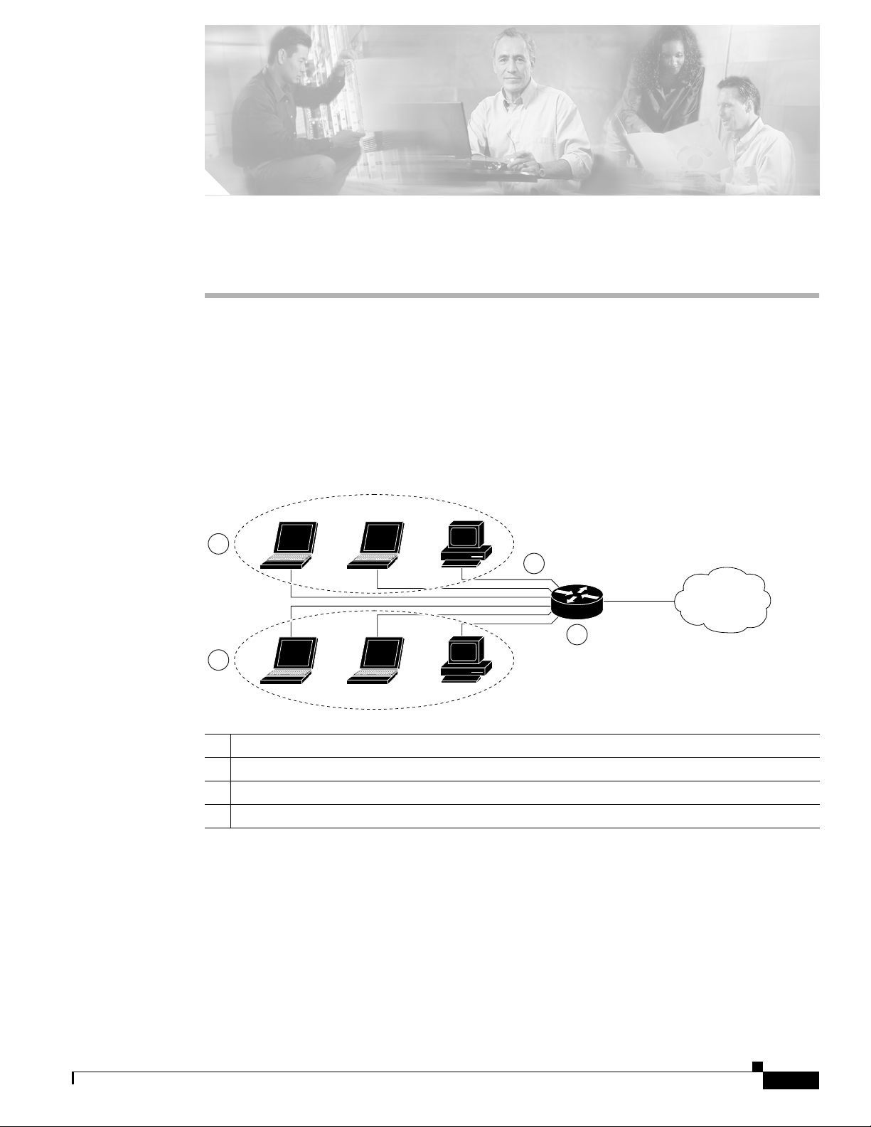
Figure 5-1 shows a typical deployment scenario with two physical LANs connected by the router and
two VLANs.
Figure 5-1 Physical and Virtual LANs with DHCP Configured on the Cisco Router
3
1
2
4
92339
1 Fast Ethernet LAN (with multiple networked devices)
2 Router and DHCP server—Cisco 1800 series integrated services router—connected to the Internet
3 VLAN 1
4 VLAN 2
DHCP
DHCP, which is described in RFC 2131, uses a client/server model for address allocation. As an
administrator,you can configure your Cisco 1800 integrated services fixed-configuration router to act as
a DHCP server, providing IP address assignment and other TCP/IP-oriented configuration information
to your workstations. DHCP frees you from having to manually assign an IP address to each client.
OL-6426-02
Cisco 1800 Series Integrated Services Routers (Fixed) Software Configuration Guide
5-1
Page 2

Configure DHCP
Note Whenever you change server properties, you must reload the server with the configuration data from the
Chapter 5 Configuring a LAN with DHCP and VLANs
When you configure a DHCP server, you must configure the server properties, policies, and DHCP
options.
Network Registrar database.
VLANs
The Cisco 1800 series integrated services routers (fixed) support eight Fast Ethernet ports on which you
can configure VLANs.
VLANs enable networks to be segmented and formed into logical groups of users, regardless of the
user’s physical location or LAN connection.
Configuration Tasks
Perform the following tasks to configure this network scenario:
• Configure DHCP
• Configure VLANs
Note The procedures in this chapter assume you have already configured basic router features as well as
PPPoE or PPPoA with NAT. If you have not performed these configurations tasks, see Chapter 1, “Basic
Router Configuration,” Chapter 3, “Configuring PPP over Ethernet with NAT,” and Chapter 4,
“Configuring PPP over ATM with NAT” as appropriate for your router.
Configure DHCP
Perform these steps to configure your router for DHCP operation, beginning in global configuration
mode:
Command Purpose
Step 1
Step 2
ip domain name name
Example:
Router(config)# ip domain name smallbiz.com
Router(config)#
ip name-server server-address1
[server-address2...server-address6]
Example:
Router(config)# ip name-server 192.168.11.12
Router(config)#
Identifiesthedefaultdomainthattherouterusesto
complete unqualified hostnames (names without a
dotted-decimal domain name).
Specifies the address of one or more Domain Name
System (DNS) servers to use for name and address
resolution.
5-2
Cisco 1800 Series Integrated Services Routers (Fixed) Software Configuration Guide
OL-6426-02
Page 3

Chapter 5 Configuring a LAN with DHCP and VLANs
Command Purpose
Step 3
ip dhcp excluded-address low-address
[high-address]
Example:
Router(config)# ip dhcp excluded-address
192.168.9.0
Configure DHCP
Specifies IP addresses that the DHCP server should
not assign to DHCP clients. In this example, we are
excluding the router address.
Step 4
Step 5
Step 6
Step 7
ip dhcp pool name
Example:
Router(config)# ip dhcp pool dpool1
Router(config-dhcp)#
network network-number [mask | prefix-length]
Example:
Router(config-dhcp)# network 10.10.0.0
255.255.255.0
Router(config-dhcp)#
import all
Example:
Router(config-dhcp)# import all
Router(config-dhcp)#
default-router address [address2...address8]
Example:
Router(config-dhcp)# default-router 10.1.1.1
Router(config-dhcp)#
Creates a DHCP address pool on the router and
enters DHCP pool configuration mode. The name
argument can be a string or an integer.
Definessubnet number (IP) address for the DHCP
address pool, optionally including the mask.
Imports DHCP option parameters into the DHCP
portion of the router database.
Specifiesupto 8 default routers for a DHCP client.
OL-6426-02
Step 8
Step 9
Step 10
dns-server address [address2...address8]
Example:
Router(config-dhcp)# dns-server 192.168.35.2
Router(config-dhcp)#
domain-name domain
Example:
Router(config-dhcp)# domain-name cisco.com
Router(config-dhcp)#
exit
Example:
Router(config-dhcp)# exit
Router(config)#
Cisco 1800 Series Integrated Services Routers (Fixed) Software Configuration Guide
Specifies up to 8 DNS servers available to a DHCP
client.
Specifies the domain name for a DHCP client.
Exits DHCP configuration mode, and enters global
configuration mode.
5-3
Page 4

Configure DHCP
Configuration Example
The following configuration example shows a portion of the configuration file for the DCHP
configuration described in this chapter.
ip dhcp excluded-address 192.168.9.0
!
ip dhcp pool dpool1
import all
network 10.10.0.0 255.255.255.0
default-router 10.10.10.10
dns-server 192.168.35.2
domain-name cisco.com
!
ip domain name smallbiz.com
ip name-server 192.168.11.12
Verify Your DHCP Configuration
Use the following commands to view your DHCP configuration.
• show ip dhcp import—Displays the optional parameters imported into the DHCP server database.
• show ip dhcp pool—Displays information about the DHCP address pools.
• show ip dhcp server statistics—Displays the DHCP server statistics, such as the number of address
pools, bindings, and so forth.
Router# show ip dhcp import
Chapter 5 Configuring a LAN with DHCP and VLANs
Address Pool Name: dpool1
Router# show ip dhcp pool
Pool dpool1 :
Utilization mark (high/low) : 100 / 0
Subnet size (first/next) : 0 / 0
Total addresses : 254
Leased addresses : 0
Pending event : none
1 subnet is currently in the pool :
Current index IP address range Leased addresses
10.10.0.1 10.10.0.1 - 10.10.0.254 0
Router# show ip dhcp server statistics
Memory usage 15419
Address pools 1
Database agents 0
Automatic bindings 0
Manual bindings 0
Expired bindings 0
Malformed messages 0
Secure arp entries 0
Message Received
BOOTREQUEST 0
DHCPDISCOVER 0
DHCPREQUEST 0
DHCPDECLINE 0
DHCPRELEASE 0
DHCPINFORM 0
5-4
Cisco 1800 Series Integrated Services Routers (Fixed) Software Configuration Guide
OL-6426-02
Page 5

Chapter 5 Configuring a LAN with DHCP and VLANs
Message Sent
BOOTREPLY 0
DHCPOFFER 0
DHCPACK 0
DHCPNAK 0
Router#
Configure VLANs
Perform these steps to configure VLANs on your router, beginning in privileged EXEC mode:
Command Purpose
Step 1
vlan database
Example:
Router# vlan database
Router(vlan)#
Configure VLANs
Enters VLAN configuration mode.
Step 2
Step 3
vlan vlan-id [media type] [name vlan-name]
Example:
Router(vlan)# vlan 2 media ethernet name
VLAN0002
Router(vlan)# vlan 3 media ethernet name
red-vlan
Router(vlan)#
exit
Example:
Router(vlan)# exit
Router#
Adds VLANs, with identifiers ranging from 2 to 1001.
For details about this command and additional
parameters that can be set, see the Cisco IOS
Switching Services Command Reference.
Updates the VLAN database, propagates it throughout
the administrative domain, and returns to privileged
EXEC mode.
OL-6426-02
Cisco 1800 Series Integrated Services Routers (Fixed) Software Configuration Guide
5-5
Page 6

Configure VLANs
Verify Your VLAN Configuration
Use the following commands to view your VLAN configuration.
• show—Entered from VLAN database mode. Displays summary configuration information for all
configured VLANs.
• show vlan-switch—Entered from privileged EXEC mode. Displays detailed configuration
information for all configured VLANs.
Router# vlan database
Router(vlan)# show
VLAN ISL Id: 1
Name: default
Media Type: Ethernet
VLAN 802.10 Id: 100001
State: Operational
MTU: 1500
Translational Bridged VLAN: 1002
Translational Bridged VLAN: 1003
VLAN ISL Id: 1002
Name: fddi-default
Media Type: FDDI
VLAN 802.10 Id: 101002
State: Operational
MTU: 1500
Bridge Type: SRB
Translational Bridged VLAN: 1
Translational Bridged VLAN: 1003
Chapter 5 Configuring a LAN with DHCP and VLANs
VLAN ISL Id: 1003
Name: token-ring-default
Media Type: Token Ring
VLAN 802.10 Id: 101003
State: Operational
MTU: 1500
Bridge Type: SRB
Ring Number: 0
Bridge Number: 1
Parent VLAN: 1005
Maximum ARE Hop Count: 7
Maximum STE Hop Count: 7
Backup CRF Mode: Disabled
Translational Bridged VLAN: 1
Translational Bridged VLAN: 1002
VLAN ISL Id: 1004
Name: fddinet-default
Media Type: FDDI Net
VLAN 802.10 Id: 101004
State: Operational
MTU: 1500
Bridge Type: SRB
Bridge Number: 1
STP Type: IBM
VLAN ISL Id: 1005
Name: trnet-default
Media Type: Token Ring Net
VLAN 802.10 Id: 101005
State: Operational
MTU: 1500
5-6
Cisco 1800 Series Integrated Services Routers (Fixed) Software Configuration Guide
OL-6426-02
Page 7

Chapter 5 Configuring a LAN with DHCP and VLANs
Bridge Type: SRB
Bridge Number: 1
STP Type: IBM
Router# show vlan-switch
VLAN Name Status Ports
---- -------------------------------- --------- ------------------------------1 default active Fa0, Fa1, Fa2, Fa3
1002 fddi-default active
1003 token-ring-default active
1004 fddinet-default active
1005 trnet-default active
VLAN Type SAID MTU Parent RingNo BridgeNo Stp BrdgMode Trans1 Trans2
---- ----- ---------- ----- ------ ------ -------- ---- -------- ------ -----1 enet 100001 1500 - - - - - 1002 1003
1002 fddi 101002 1500 - - - - - 1 1003
1003 tr 101003 1500 1005 0 - - srb 1 1002
1004 fdnet 101004 1500 - - 1 ibm - 0 0
1005 trnet 101005 1500 - - 1 ibm - 0 0
Router#
Configure VLANs
OL-6426-02
Cisco 1800 Series Integrated Services Routers (Fixed) Software Configuration Guide
5-7
Page 8

Configure VLANs
Chapter 5 Configuring a LAN with DHCP and VLANs
5-8
Cisco 1800 Series Integrated Services Routers (Fixed) Software Configuration Guide
OL-6426-02
 Loading...