

Page 1

CHA PT ER
1
Cisco 1721 Router Overview
This chapter introduces the Cisco 1721 router, also referred to in this guide as the
router, and covers the following topics:
• Key Features
• Back Panel Ports and LEDs
• Front Panel LEDs
• Router Memory
• Unpacking the Router
• Additional Required Equipment
78-13834-02
Cisco 1721 Router Hardware Installation Guide
1-1
Page 2
Key Features
Key Features
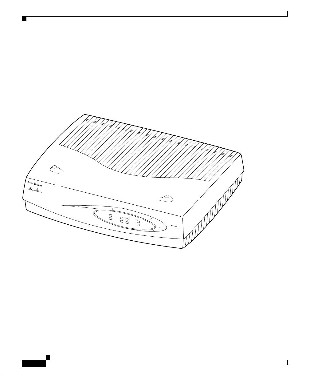
The Cisco 1721 router (see Figure 1-1) is a small, modular desktop router that
links small- to medium-size remote Ethernet and Fast Ethernet LANs over one to
four WAN connections to regional and central offices. Tab le 1-1 lists the key
features of the router.
Figure 1-1 Cisco 1721 Router
Chapter 1 Cisco 1721 Router Overview
1-2
PWR
W
IC
0
ACT/CH0
W
IC1
ACT/CH0
E
TH
OK
ACT
ACT/CH1
ACT/CH1
COL
Cisco 1721 Router Hardware Installation Guide
Cisco
1700
SERIES
ROUTER
12154
78-13834-02
Page 3

Chapter 1 Cisco 1721 Router Overview
Key Features
Table 1-1 Key Features
Feature Description
One Fast Ethernet
(10/100BASE-TX) port
Two Cisco WAN interface card
(WIC) slots
Console port Supports router configuration and management with a
Auxiliary port Supports modem connection to the router, which can be
VPN hardware-assisted 3DES
encryption module
SNMP support Router can be managed over a network using Simple Network
AutoInstall support Configuration files can be easily downloaded to the router over
Kensington security slot Router can be secured to a desktop or other surface using
Cisco ConfigMaker support You can set up networks that include the Cisco 1721 router
Support for Cisco IOS software
features
• Operates in full- or half-duplex mode (with manual
override available).
• Supports autosensing for 10- or 100-Mbps operation.
• Supports IEEE 802.1Q VLAN encapsulation.
• Supports a combination of any two of the following WICs:
ISDN BRI, 56-kbps DSU/CSU, FT1/T1 DSU/CSU,
high-speed serial, dual-serial, ADSL, G.SHDSL, and
Ethernet.
• The WAN interface configuration can be changed as your
network requirements change.
directly-connected terminal or PC. Supports up to 115.2 kbps.
configured and managed from a remote location. Supports up to
115.2 kbps.
Provides IPSEC DES and 3DES hardware encryption.
Management Protocol (SNMP).
a WAN connection.
Kensington lockdown equipment.
using the Cisco ConfigMaker application, a wizards-based
software tool that helps you easily configure and address Cisco
routers, access servers, hubs, switches, and networks.
Supports IP, IPX, AppleTalk, IBM, Open Shortest Path First
(OSPF), NetWare Link Services Protocol (NLSP), Resource
Reservation Protocol (RSVP), encryption, network address
translation, and the Cisco IOS Firewall Feature Set.
78-13834-02
Cisco 1721 Router Hardware Installation Guide
1-3
Page 4

Back Panel Ports and LEDs
Back Panel Ports and LEDs
This section describes the router back panel ports and LEDs, which are shown in
Figure 1-2 and described in Tab le 1- 2 and Tabl e 1-3.
Figure 1-2 Back Panel Ports and LEDs
Kensington-compatible
locking socket
WIC 0 slot WIC 1 slot
Console port
Chapter 1 Cisco 1721 Router Overview
Power switch
CONSOLE
AUX
Auxiliary port
Model
Cisco 1721
TD
SEE MANUAL BEFORE INSTALLATION
WIC 0
OK LED
ALLPRD
56K
FDX LINK100WIC 0 OK WIC 1 OKMOD OK
FDX/100/
LINK LEDs
10/100 ETHERNET
10/100-Mbps
Ethernet port
DSU
CD
Table 1-2 Back Panel Connectors
Connector/Slot Label/Color Description
Ethernet port 10/100
ETHERNET
(yellow)
Connects the router to the local Ethernet network
through this port. This port autosenses the speed
(10 Mbps or 100 Mbps) and duplex mode (full- or half-)
of the device to which it is connected and then operates
at the same speed and in the same duplex mode.
Auxiliary port AUX
(black)
Console port CONSOLE
(blue)
Connects to a modem for remote configuration with
Cisco IOS software.
Connects to a terminal or PC for local configuration
using Cisco IOS software.
MOD OK
LED
WIC 1 OK
+5, +12, -12 VDC
65524
Powe r
socket
LED
1-4
Cisco 1721 Router Hardware Installation Guide
78-13834-02
Page 5

Chapter 1 Cisco 1721 Router Overview
Front Panel LEDs
Table 1-2 Back Panel Connectors (continued)
Connector/Slot Label/Color Description
WIC slot 0
(WIC0)
WIC slot 1
(WIC1)
Table 1-3 Back Panel LEDs
LED Label Color Description
WIC0 OK Green On when a WIC is correctly inserted in the card slot.
FDX Green On solid—Ethernet port is operating in full-duplex mode.
100 Green On solid—Ethernet port is operating at 100 Mbps.
No label Supports one Cisco WIC. For detailed information, refer
to the Cisco WAN Interface Cards Hardware Installation
Guide, which comes with every card.
No label Supports one Cisco WIC. For detailed information, refer
to the Cisco WAN Interface Cards Hardware Installation
Guide, which comes with every card.
Use the back panel LEDs during router installation to confirm that you have
correctly connected all the cables to the router.
Off—Ethernet port is operating in half-duplex mode.
Off—Ethernet port is operating at 10 Mbps.
LINK Green On when the Ethernet link is up.
MOD OK Green On when the VPN hardware encryption module is installed and
recognized by the IOS.
WIC1 OK Green On when a WIC is correctly inserted in the card slot.
Front Panel LEDs
Use the router front panel LEDs to determine network activity and status on the
Ethernet port and on the WIC ports. The front panel LEDs are illustrated in
Figure 1-3 and described in Tab le 1- 4.
Cisco 1721 Router Hardware Installation Guide
78-13834-02
1-5
Page 6

Front Panel LEDs
Figure 1-3 Front Panel LEDs
Chapter 1 Cisco 1721 Router Overview
PWR
OK
WIC0
ACT/CH0
ACT/CH1
WIC1
ACT/CH0
ACT/CH1
ETH
ACT
COL
65537
Table 1-4 Front Panel LEDs
LED Label Color Description
PWR Green On means that DC power is being supplied to the router.
OK Green On means that the router has successfully booted up and the software is
functional. This LED blinks during the power-on self-test (POST).
See the section “OK LED Diagnostics” in Chapter 3,
“Troubleshooting,” for information on how to use this LED for router
diagnostics.
WIC0
ACT/CH0 Green Serial and DSU/CSU cards—Blinks when data is being sent to or
received from the port on the card in the WIC0 slot.
ISDN cards—On solid when the first ISDN B channel is up for the card
in the WIC0 slot.
2-port serial cards—Blinks when data is being sent to or received from
the first port on the 2-port card in the WIC0 slot.
ACT/CH1 Green Serial and CSU/DSU cards—Remains off.
ISDN cards—On solid when the second ISDN B channel is up for the
card in the WIC0 slot
2-port serial cards—Blinks when data is being sent to or received from
the second port on the 2-port card in the WIC0 slot.
1-6
Cisco 1721 Router Hardware Installation Guide
78-13834-02
Page 7

Chapter 1 Cisco 1721 Router Overview
Router Memory
Table 1-4 Front Panel LEDs (continued)
LED Label Color Description
WIC1
ACT/CH0 Green Serial and DSU/CSU cards—Blinks when data is being sent to or
received from the port on the card in the WIC1 slot.
ISDN cards—On solid when the first ISDN B channel is up for the card
in the WIC1 slot.
2-port serial cards—Blinks when data is being sent to or received from
the first port on the 2-port card in the WIC1 slot.
ACT/CH1 Green Serial and DSU/CSU cards—Remains off.
ISDN cards—On solid when the second ISDN B channel is up for the
card in the WIC1 slot.
2-port serial cards—Blinks when data is being sent to or received from
the second port on the 2-port card in the WIC1 slot.
ETH
ACT Green Blinks when there is network activity on the Ethernet port.
COL Yellow Blinks when there are packet collisions on the local Ethernet network.
Router Memory
This section describes the types of memory stored in the router and how to find
out how much of each type of memory is stored in the router.
For instruction on how to upgrade memory in the router, see Appendix C,
“Installing and Upgrading Memory and Virtual Private Network Modules.”
78-13834-02
Cisco 1721 Router Hardware Installation Guide
1-7
Page 8

Router Memory
Types of Memory
The Cisco 1721 router has the following types of memory:
• Dynamic random-access memory (DRAM)—This is the main storage
• Nonvolatile random-access memory (NVRAM)—This type of memory
• Flash memory—This special kind of erasable, programmable memory
Chapter 1 Cisco 1721 Router Overview
memory for the router. DRAM is also called working storage. It contains the
dynamic configuration information. The Cisco 1721 router stores a working
copy of the Cisco IOS software, dynamic configuration information, and
routing table information in DRAM.
contains a backup copy of your configuration. If the power is lost or the router
is turned off, this backup copy enables the router to return to operation
without reconfiguration.
contains a copy of the Cisco IOS software. The Flash memory structure can
store multiple copies of the Cisco IOS software. You can load a new level of
the operating system in every router in your network and then, when
convenient, upgrade the whole network to the new level.
Amounts of Memory
The Cisco 1721 router supports a maximum of 32MB Flash memory and 128MB
DRAM. Use the show version command to view the amount of DRAM, NVRAM,
and Flash memory stored in your router. The following example of the
show version command output displays the amount of memory in this router.
1721# show version
Cisco Internetwork Operating System Software
IOS (tm) C1700 Software (C1700-K9SY-M), Version 12.2(4)YA EARLY
DEPLOYMENT RELEASE SOFTWARE (fc1)
TAC Support: http://www.cisco.com/tac
Copyright (c) 1986-2002 by cisco Systems, Inc.
Compiled Mon 14-Jan-02 16:34 by ramesh
Image text-base: 0x80008108, data-base: 0x80BC77E8
ROM: System Bootstrap, Version 12.2(7r)XM1, RELEASE SOFTWARE (fc1)
1721 uptime is 4 days, 23 hours, 54 minutes
System returned to ROM by reload
Running default software
Cisco 1721 Router Hardware Installation Guide
1-8
78-13834-02
Page 9

Chapter 1 Cisco 1721 Router Overview
cisco 1721 (MPC860P) processor (revision 0x101) with 36864K/12288K
bytes of memory.
Processor board ID VEN0539000D (3033334544), with hardware revision
0000
MPC860P processor: part number 5, mask 2
Bridging software.
X.25 software, Version 3.0.0.
1 Ethernet/IEEE 802.3 interface(s)
1 FastEthernet/IEEE 802.3 interface(s)
2 Serial network interface(s)
1 Virtual Private Network (VPN) Modules(s)
32K bytes of non-volatile configuration memory.
16384K bytes of processor board System flash (Read/Write)
Configuration register is 0x0
Unpacking the Router
Table 1-5 lists the items that come with your router. All these items are in the
accessory kit that is inside the box that your router came in.
Unpacking the Router
Table 1-5 Router Box Contents
Power cord (black)
•
• Power supply
• DB-25 to DB-9 adapter
• Console cable, RJ-45 to DB-9 (light blue)
• Product documentation
Additional Required Equipment
Depending on your local network and on which Cisco WICs you install in your
router, you will require other items, listed in Tabl e 1 -6, to complete your router
installation.
Cisco 1721 Router Hardware Installation Guide
78-13834-02
1-9
Page 10

Chapter 1 Cisco 1721 Router Overview
Additional Required Equipment
Table 1-6 Additional Required Equipment
Equipment When You Use It
Ethernet hub A hub connects pieces of network equipment (including the
Cisco 1721 router) to create a network. You can use a 10-, 100-, or
10/100-Mbps hub with the Cisco 1721 router.
Ethernet switch A switch connects pieces of network equipment (including the
Cisco 1721 router) to create a network. You can use a 10-, 100-, or
10/100-Mbps switch with the Cisco 1721 router.
Phillips screwdriver Although the WICs use thumbscrews, you might need a Phillips
screwdriver to loosen the WIC slot cover.
Cisco WIC In order to make a WAN connection, the Cisco 1721 router must
have a supported WIC installed. The router supports up to two
cards. You can order the cards when you order the router, and they
will be installed for you. Or, you can order the cards separately, after
you receive the router, and then install them yourself.
Straight-through RJ-45-to-RJ-45
cable
Serial cable This cable connects a serial card to serial services. You must order
NT-1 Some ISDN service providers require a Network Termination 1
Asynchronous modem Connect a modem to the AUX port on the router when you want to
This cable connects the router to the Ethernet LAN and connects the
WICs to various WAN services, including ISDN, T1/FT1, and
56-kbps services. You will need one cable for each connection that
requires this cable type.
this cable from Cisco. For detailed information about serial cable
types, refer to the Cisco WAN Interface Cards Hardware
Installation Guide, which comes with every card.
(NT-1) device to connect an ISDN S/T port to the ISDN line.
configure the router from a remote location.
1-10
Cisco 1721 Router Hardware Installation Guide
78-13834-02
 Loading...