

Page 1

Quick Start Guide
Cisco 1721 Router Cabling and Installation
Including License and Warranty
1 Cisco One-Year Limited Hardware Warranty Terms
2 Overview
3 Parts List
4 Connect the Power Supply
5 Connect the Router to Your Local Network
6 Installing the WICs
7 Connecting a PC to the Router
8 Verify Your Installation
9 Configure the Router Using Cisco Router and Security Device Manager
10 For More Information
11 Obtaining Documentation
12 Documentation Feedback
13 Cisco Product Security Overview
14 Obtaining Technical Assistance
15 Obtaining Additional Publications and Information
Page 2

1 Cisco One-Year Limited Hardware Warranty Terms
There are special terms applicable to your hardware warranty and various services that you can use during the warranty period.
Your formal Warranty Statement, including the warranties and license agreements applicable to Cisco software, is available on
Cisco.com. Follow these steps to access and download the Cisco Information Packet and your warranty and license agreements
from Cisco.com.
1. Launch your browser, and go to this URL:
http://www.cisco.com/univercd/cc/td/doc/es_inpck/cetrans.htm
The Warranties and License Agreements page appears.
2. To read the Cisco Information Packet, follow these steps:
a. Click the Information Packet Number field, and make sure that the part number 78-5235-03A0 is highlighted.
b. Select the language in which you would like to read the document.
c. Click Go.
The Cisco Limited Warranty and Software License page from the Information Packet appears.
d. Read the document online, or click the PDF icon to download and print the document in Adobe Portable Document
Format (PDF).
Note You must have Adobe Acrobat Reader to view and print PDF files. You can download the reader from Adobe’s
website: http://www.adobe.com
3. To read translated and localized warranty information about your product, follow these steps:
a. Enter this part number in the Warranty Document Number field:
78-10747-01C0
b. Select the language in which you would like to view the document.
c. Click Go.
The Cisco warranty page appears.
d. Read the document online, or click the PDF icon to download and print the document in Adobe Portable Document
Format (PDF).
You can also contact the Cisco service and support website for assistance:
http://www.cisco.com/public/Support_root.shtml.
Duration of Hardware Warranty
One (1) Year
Replacement, Repair, or Refund Policy for Hardware
Cisco or its service center will use commercially reasonable efforts to ship a replacement part within ten (10) working days after
receipt of a Return Materials Authorization (RMA) request. Actual delivery times can vary, depending on the customer location.
Cisco reserves the right to refund the purchase price as its exclusive warranty remedy.
To Receive a Return Materials Authorization (RMA) Number
Contact the company from whom you purchased the product. If you purchased the product directly from Cisco, contact your Cisco
Sales and Service Representative.
2
Page 3

Complete the information below, and keep it for reference.
Company product purchased from
Company telephone number
Product model number
Product serial number
Maintenance contract number
2 Overview
This document describes the steps for installing your Cisco 1721 router with its complement of WAN interface cards (WICs).
Additional documentation can be found on Cisco.com.
Product Serial Number Location
The serial number label for Cisco 1721 router is located on the rear of the chassis, to the right of the power switch.
3 Parts List
Your router package should include the following items:
• One Cisco 1721 router
• One blue RJ-45-to-DB-9 console cable
• One DB-9-to-DB-25 adapter
• One black power supply
• One black power supply cord
• Product documentation
Items You Need to Provide
Depending on your network environment, you may need to provide some of the following items to install the router:
• Ethernet hub or switch to connect the router to the local network
• Straight-through Ethernet cables (RJ-45-to-RJ-45) to connect the router to a broadband (xDSL or cable) modem and to a
hub or switch
• Cisco WIC(s), if you did not order the router with WICs already installed
• Cables to connect WICs to the appropriate WAN services
• External NT-1 or data service unit/channel service unit (DSU/CSU), if needed, to connect a WIC to WAN services
4 Connect the Power Supply
Follow these steps to connect the router to the power supply:
Step 1 Connect the attached power supply cord to the power socket (labeled +5, +12, -12 VDC) on the back panel of the
router, as shown in Figure 1.
3
Page 4
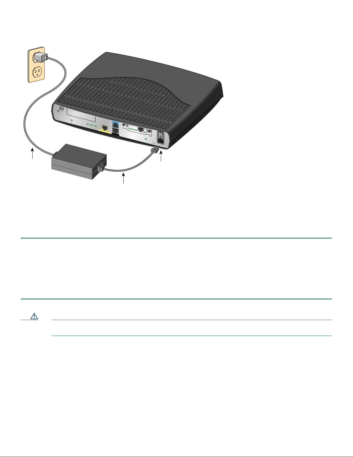
Figure 1 Connecting the Power Supply
Cisco 1720
WIC0OK
FDX
100
LNK
10/100 ETHERNET
C
ON
S
OL
E
A
UX
12237
TD
RD
LP
AL
SEE
MANUAL
BEF
CD
ORE INST
ALLATION
D
S
U
56
K
WIC1OK
+5, +12, -12 VD
C
Separate
power cord
Power socket
Power supply
Attached
power supply cord
Step 2 Connect the separate power cord to the power socket on the power supply.
Step 3 Connect the other end of the separate power cord to a power outlet.
Step 4 Turn on the router by pressing the power switch to the on ( | ) position.
Step 5 Confirm that the router has power by checking that the PWR LED on the front panel is on.
5 Connect the Router to Your Local Network
You need to provide straight-through Ethernet cables for connecting the router to the local Ethernet network. For more
information on these cables, refer to the “Cabling Specifications” chapter in the hardware installation guide that came with the
router. Follow these steps to connect the router to your local network:
Step 1 Connect one end of an Ethernet cable to the 10/100 ETHERNET port (the yellow port) as shown in Figure 2.
Caution Always connect the Ethernet cable to the Ethernet ports on the router. Accidentally connecting the cable to the
wrong port can damage your router.
4
Page 5
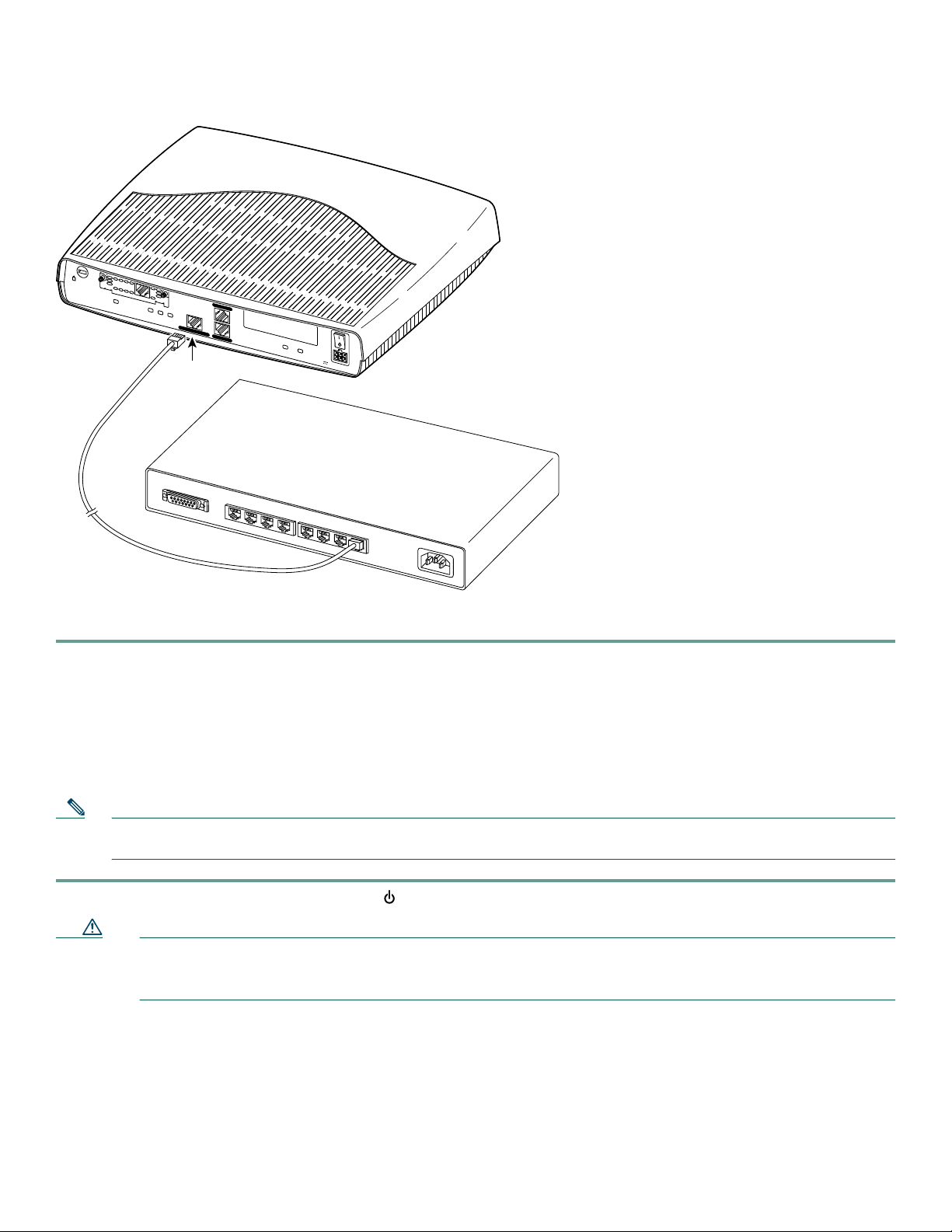
Figure 2 Connecting the Router to Your Local Network
TD
RD
LP
AL
S
E
E
M
A
WIC0OK
N
U
A
L
B
E
F
CD
O
R
E
I
N
S
T
A
L
L
A
T
I
O
N
FDX
100
Ethernet port
DSU
56K
LINK
10/100 ETHERNET
10/100
C
ONS
OLE
A
UX
MOD OK
WIC1OK
+
5
, +
1
2
, -12
V
D
C
Ethernet hub or switch
(10, 100, or 10/100 Mbps)
Model
Cisco 1721
AUI
8
7
6
5
4
3
2
1
65525
Straight-through
Ethernet cable
Step 2 Connect the other end of the cable to a port on the hub or switch.
6 Installing the WICs
Look for a WIC in one or both of the slots on the back of the router. If a card is already installed, it can be connected to a WAN
line in accordance with the <Emphasis>Cisco WAN Interface Cards Hardware Installation Guide that came with the card. To
install a card in either slot, follow these instructions.
Note If you are installing a WIC in the router for the first time, install the card in the WIC0 slot to ensure that your software
configuration will not be affected if you install a second card at a later time.
Step 1 Set the power switch to the STANDBY ( ) position and confirm the router is not connected to the power supply.
Caution Power must be removed from the system prior to installing or removing WICs to avoid damaging them. When WICs
are pushed into or pulled out of a router that is powered up, it is likely that they could be damaged electrically and
will no longer function.
Step 2 Remove the screws that hold the slot cover in place, as shown in Figure 3, and then remove the slot cover. You should
be able to loosen the screws using your fingers; however, if the screws are very tight, you might need to use a Phillips
screwdriver.
5
Page 6

Figure 3 Removing the WIC Slot Cover
65526
Model
Cisco 1721
WIC0OK
FDX
LINK100
WAN interface card slot cover
10/100 ETHERNET
CONSOLE
AUX
MOD OK
WIC1OK
+5, +12, -12 VDC
Step 3 Hold the WIC by the edges on either side of the card front panel, and line up the card edges with the guides inside the
card slot, as shown in Figure 4.
Figure 4 Inserting a WIC
65527
Model
Cisco 1721
WIC0OK
TD
RD
LP
AL
SE
E
M
A
N
U
A
L
B
E
FO
CD
R
E
IN
S
T
A
LL
D
S
A
U
TIO
N
56K
Guides
FDX
LINK100
10/100 ETHERNET
CONSOLE
AUX
MOD OK
WIC1OK
+5, +12, -12 VDC
WAN interface card
Step 4 Insert the card in the slot. Gently push it into the router until the front panel of the card is flush with the back panel of
the router.
Step 5 Tighten the screws.
6
Page 7

7 Connecting a PC to the Router
In order for the Cisco IOS software to be used to configure the router, the router must be connected to a terminal or a PC with
terminal emulation software. Terminal emulation software should be configured with the following settings: 9600 baud, 8 data
bits, no parity bits, and 1 stop bit. The Cisco 1700 Router Software Configuration Guide describes how to configure the router
by using Cisco IOS software.
Note If it is installed on your router, you can use Security Device Manager, a web-based configuration tool, to configure your
router. If you want to use Security Device Manager, skip this section, and complete sections 8 and 9. If you want to use
the Cisco IOS command line interface (CLI), you can use the information in this section to connect a PC to the router’s
console port so that you can access the IOS CLI.
Follow these steps to connect the router to a terminal or PC:
Step 1 Connect the RJ-45 end of the included console cable to the CONSOLE port on the back panel of the router, as shown
in Figure 5.
Figure 5 Connecting the Console Cable to the Router
65528
TD
RD
LP
AL
Model
Cisco 1721
Blue console cable
SEE MANUAL BEFORE INSTALLATION
WIC0OK
CD
D
S
U
5
6
K
FDX
100
LINK
10/100 ETHERNET
CONSOLE
AUX
MOD OK
WIC1OK
+5, +12, -12 VDC
Console port
To PC or terminal
Step 2 Connect the DB-9 end of the console cable to the console port (also called the serial port) on your PC. If this adapter
does not fit your PC console port, you must provide an adapter that fits.
7
Page 8

8 Verify Your Installation
You can verify that you have correctly installed your router by checking the LEDs as described in Table 1.
Table 1 LEDs That Verify Installation
LED Panel What to Look For
PWR Front On when power is being supplied to the router.
OK Front On when the router software is loaded and
functional.
Blinking when the router is running a power-on
self-test (POST). Continual blinking can indicate a
problem with the router, although the LED will
also blink if the router is in ROMMON mode.
Refer to the “Troubleshooting” chapter in the
Cisco 1721 Router Hardware Installation Guide
for more information.
LINK Back On when the router is correctly connected to the
Ethernet network through the 10/100
ETHERNET port.
FDX Back On when the Ethernet port is operating in
full-duplex mode.
100 Back On when the 10/100 ETHERNET port is
operating at 100 Mbps.
ETH ACT Front Blinking when there is network traffic on the local
Ethernet LAN.
WIC0 ACT and WIC1 ACT Front On solid or blinking when there is data traffic on
the corresponding WIC port. Refer to Table 1-4 in
Chapter 1, “Cisco 1721 Router Overview,” of the
Cisco 1721 Router Hardware Installation Guide,
for detailed information.
WIC0 OK and WIC1 OK Back On when a WIC is correctly installed in the
corresponding WIC slot.
MOD OK Back On when the VPN hardware encryption module is
installed and recognized by the IOS.
9 Configure the Router Using Cisco Router and Security Device Manager
Cisco Router and Security Device Manager (SDM) is a web-based configuration tool that allows you to configure LAN
and WAN interfaces, routing, Network Address Translation (NAT), firewalls, VPNs, and other features on your router.
If SDM is installed on your router, configure the router by following the instructions in the Cisco Router and Security
Device Manager (SDM) Quick Start Guide. If this document was not shipped with your router, you can obtain SDM and
instructions for installing it on your router from the following
http://www.cisco.com/pcgi-bin/tablebuild.pl/sdm
To obtain the SDM release notes, and other SDM documentation, go to http://www.cisco.com/go/sdm and click the Technical
Documentation link.
8
location:
Page 9

10 For More Information
For more information about installing or configuring your Cisco 1721 router, see the following:
• Cisco 1721 Router Hardware Installation Guide, available on Cisco.com
• Cisco 1700 Router Software Configuration Guide, available on Cisco.com
• Cisco Security Device Manager Troubleshooting Guide, available on Cisco.com
• The Cisco Warranty card, included in the accessory kit, which lists telephone numbers, e-mail addresses, and World Wide
Web URLs for getting information directly from Cisco Systems
For more information about SDM, visit http://www.cisco.com/go/sdm.
11 Obtaining Documentation
Cisco documentation and additional literature are available on Cisco.com. Cisco also provides several ways to obtain technical
assistance and other technical resources. These sections explain how to obtain technical information from Cisco Systems.
Cisco.com
You can access the most current Cisco documentation at this URL:
http://www.cisco.com/univercd/home/home.htm
You can access the Cisco website at this URL:
http://www.cisco.com
You can access international Cisco websites at this URL:
http://www.cisco.com/public/countries_languages.shtml
Documentation DVD
Cisco documentation and additional literature are available in a Documentation DVD package, which may have shipped with
your product. The Documentation DVD is updated regularly and may be more current than printed documentation. The
Documentation DVD package is available as a single unit.
Registered Cisco.com users (Cisco direct customers) can order a Cisco Documentation DVD (product number
DOC-DOCDVD=) from the Ordering tool or Cisco Marketplace.
Cisco Ordering tool:
http://www.cisco.com/en/US/partner/ordering/
Cisco Marketplace:
http://www.cisco.com/go/marketplace/
Ordering Documentation
You can find instructions for ordering documentation at this URL:
http://www.cisco.com/univercd/cc/td/doc/es_inpck/pdi.htm
You can order Cisco documentation in these ways:
• Registered Cisco.com users (Cisco direct customers) can order Cisco product documentation from the Ordering tool:
http://www.cisco.com/en/US/partner/ordering/
• Nonregistered Cisco.com users can order documentation through a local account representative by calling Cisco Systems
Corporate Headquarters (California, USA) at 408 526-7208 or, elsewhere in North America, by calling 1 800 553-NETS
(6387).
9
Page 10

12 Documentation Feedback
You can send comments about technical documentation to bug-doc@cisco.com.
You can submit comments by using the response card (if present) behind the front cover of your document or by writing to the
following address:
Cisco Systems
Attn: Customer Document Ordering
170 West Tasman Drive
San Jose, CA 95134-9883
We appreciate your comments.
13 Cisco Product Security Overview
Cisco provides a free online Security Vulnerability Policy portal at this URL:
http://www.cisco.com/en/US/products/products_security_vulnerability_policy.html
From this site, you can perform these tasks:
• Report security vulnerabilities in Cisco products.
• Obtain assistance with security incidents that involve Cisco products.
• Register to receive security information from Cisco.
A current list of security advisories and notices for Cisco products is available at this URL:
http://www.cisco.com/go/psirt
If you prefer to see advisories and notices as they are updated in real time, you can access a Product Security Incident Response
Team Really Simple Syndication (PSIRT RSS) feed from this URL:
http://www.cisco.com/en/US/products/products_psirt_rss_feed.html
Reporting Security Problems in Cisco Products
Cisco is committed to delivering secure products. We test our products internally before we release them, and we strive to correct
all vulnerabilities quickly. If you think that you might have identified a vulnerability in a Cisco product, contact PSIRT:
• Emergencies—security-alert@cisco.com
• Nonemergencies— psirt@cisco.com
Tip We encourage you to use Pretty Good Privacy (PGP) or a compatible product to encrypt any sensitive information that
you send to Cisco. PSIRT can work from encrypted information that is compatible with PGP versions 2.x through 8.x.
Never use a revoked or an expired encryption key. The correct public key to use in your correspondence with PSIRT is the one
that has the most recent creation date in this public key server list:
http://pgp.mit.edu:11371/pks/lookup?search=psirt%40cisco.com&op=index&exact=on
In an emergency, you can also reach PSIRT by telephone:
• 1 877 228-7302
• 1 408 525-6532
10
Page 11

14 Obtaining Technical Assistance
For all customers, partners, resellers, and distributors who hold valid Cisco service contracts, Cisco Technical Support provides
24-hour-a-day, award-winning technical assistance. The Cisco Technical Support Website on Cisco.com features extensive
online support resources. In addition, Cisco Technical Assistance Center (TAC) engineers provide telephone support. If you do
not hold a valid Cisco service contract, contact your reseller.
Cisco Technical Support Website
The Cisco Technical Support Website provides online documents and tools for troubleshooting and resolving technical issues
with Cisco products and technologies. The website is available 24 hours a day, 365 days a year, at this URL:
http://www.cisco.com/techsupport
Access to all tools on the Cisco Technical Support Website requires a Cisco.com user ID and password. If you have a valid service
contract but do not have a user ID or password, you can register at this URL:
http://tools.cisco.com/RPF/register/register.do
Note Use the Cisco Product Identification (CPI) tool to locate your product serial number before submitting a web or phone
request for service. You can access the CPI tool from the Cisco Technical Support Website by clicking the Tools &
Resources link under Documentation & Tools. Choose Cisco Product Identification Tool from the Alphabetical Index
drop-down list, or click the Cisco Product Identification Tool link under Alerts & RMAs. The CPI tool offers three
search options: by product ID or model name; by tree view; or for certain products, by copying and pasting show
command output. Search results show an illustration of your product with the serial number label location highlighted.
Locate the serial number label on your product and record the information before placing a service call.
Submitting a Service Request
Using the online TAC Service Request Tool is the fastest way to open S3 and S4 service requests. (S3 and S4 service requests are
those in which your network is minimally impaired or for which you require product information.) After you describe your
situation, the TAC Service Request Tool provides recommended solutions. If your issue is not resolved using the recommended
resources, your service request is assigned to a Cisco TAC engineer. The TAC Service Request Tool is located at this URL:
http://www.cisco.com/techsupport/servicerequest
For S1 or S2 service requests or if you do not have Internet access, contact the Cisco TAC by telephone. (S1 or S2 service requests
are those in which your production network is down or severely degraded.) Cisco TAC engineers are assigned immediately to
S1 and S2 service requests to help keep your business operations running smoothly.
To open a service request by telephone, use one of the following numbers:
Asia-Pacific: +61 2 8446 7411 (Australia: 1 800 805 227)
EMEA: +32 2 704 55 55
USA: 1 800 553-2447
For a complete list of Cisco TAC contacts, go to this URL:
http://www.cisco.com/techsupport/contacts
Definitions of Service Request Severity
To ensure that all service requests are reported in a standard format, Cisco has established severity definitions.
Severity 1 (S1)—Your network is “down,” or there is a critical impact to your business operations. You and Cisco will commit
all necessary resources around the clock to resolve the situation.
Severity 2 (S2)—Operation of an existing network is severely degraded, or significant aspects of your business operation are
negatively affected by inadequate performance of Cisco products. You and Cisco will commit full-time resources during normal
business hours to resolve the situation.
11
Page 12

Severity 3 (S3)—Operational performance of your network is impaired, but most business operations remain functional. You
and Cisco will commit resources during normal business hours to restore service to satisfactory levels.
Severity 4 (S4)—You require information or assistance with Cisco product capabilities, installation, or configuration. There is
little or no effect on your business operations.
15 Obtaining Additional Publications and Information
Information about Cisco products, technologies, and network solutions is available from various online and printed sources.
• Cisco Marketplace provides a variety of Cisco books, reference guides, and logo merchandise. Visit Cisco Marketplace, the
company store, at this URL:
http://www.cisco.com/go/marketplace/
• Cisco Press publishes a wide range of general networking, training and certification titles. Both new and experienced users
will benefit from these publications. For current Cisco Press titles and other information, go to Cisco Press at this URL:
http://www.ciscopress.com
• Packet magazine is the Cisco Systems technical user magazine for maximizing Internet and networking investments. Each
quarter, Packet delivers coverage of the latest industry trends, technology breakthroughs, and Cisco products and solutions,
as well as network deployment and troubleshooting tips, configuration examples, customer case studies, certification and
training information, and links to scores of in-depth online resources. You can access Packet magazine at this URL:
http://www.cisco.com/packet
• iQ Magazine is the quarterly publication from Cisco Systems designed to help growing companies learn how they can use
technology to increase revenue, streamline their business, and expand services. The publication identifies the challenges
facing these companies and the technologies to help solve them, using real-world case studies and business strategies to help
readers make sound technology investment decisions. You can access iQ Magazine at this URL:
http://www.cisco.com/go/iqmagazine
• Internet Protocol Journal is a quarterly journal published by Cisco Systems for engineering professionals involved in
designing, developing, and operating public and private internets and intranets. You can access the Internet Protocol Journal
at this URL:
http://www.cisco.com/ipj
• World-class networking training is available from Cisco. You can view current offerings at this URL:
http://www.cisco.com/en/US/learning/index.html
12
Page 13

14 15
13
Page 14

Page 15

Page 16

Corporate Headquarters
Cisco Systems, Inc.
170 West Tasman Drive
San Jose, CA 95134-1706
USA
www.cisco.com
Tel: 408 526-4000
800 553-NETS (6387)
Fax: 408 526-4100
European Headquarters
Cisco Systems International BV
Haarlerbergpark
Haarlerbergweg 13-19
1101 CH Amsterdam
The Netherlands
www-europe.cisco.com
Tel: 31 0 20 357 1000
Fax: 31 0 20 357 1100
Americas Headquarters
Cisco Systems, Inc.
170 West Tasman Drive
San Jose, CA 95134-1706
USA
www.cisco.com
Tel: 408 526-7660
Fax: 408 527-0883
Asia Pacific Headquarters
Cisco Systems, Inc.
168 Robinson Road
#28-01 Capital Tower
Singapore 068912
www.cisco.com
Tel: +65 6317 7777
Fax: +65 6317 7799
Cisco Systems has more than 200 offices in the following countries. Addresses, phone numbers, and fax numbers are listed on the
Cisco Web site at www.cisco.com/go/offices
Argentina • Australia • Austria • Belgium • Brazil • Bulgaria • Canada • Chile • China PRC • Colombia • Costa Rica • Croatia • Cyprus • Czech Republic • Denmark
Dubai, UAE • Finland • France • Germany • Greece • Hong Kong SAR • Hungary • India • Indonesia • Ireland • Israel • Italy • Japan • Korea • Luxembourg • Malaysia
Mexico • The Netherlands • New Zealand • Norway • Peru • Philippines • Poland • Portugal • Puerto Rico • Romania • Russia • Saudi Arabia • Scotland • Singapore
Slovakia • Slovenia • South Africa • Spain • Sweden • Switzerland • Taiwan • Thailand • Turkey • Ukraine • United Kingdom • United States • Venezuela • Vietnam
Zimbabwe
CCSP, CCVP, the Cisco Square Bridge logo, Follow Me Browsing, and StackWise are trademarks of Cisco Systems, Inc.; Changing the Way We Work, Live, Play, and Learn, and iQuick Study are service marks
of Cisco Systems, Inc.; and Access Registrar, Aironet, ASIST, BPX, Catalyst, CCDA, CCDP, CCIE, CCIP, CCNA, CCNP, Cisco, the Cisco Certified Internetwork Expert logo, Cisco IOS, Cisco Press, Cisco
Systems, Cisco Systems Capital, the Cisco Systems logo, Cisco Unity, Empowering the Internet Generation, Enter prise/Solver, EtherChannel, EtherFast, EtherSwitch, Fast Step, FormShare, GigaDrive, GigaStack,
HomeLink, Internet Quotient, IOS, IP/TV, iQ Expertise, the iQ logo, iQ Net Readiness Scorecard, LightStream, Linksys, MeetingPlace, MGX, the Networkers logo, Networking Academy, Network Registrar,
Packet, PIX, Post-Routing, Pre-Routing, ProConnect, RateMUX, ScriptShare, SlideCast, SMARTnet, StrataView Plus, TeleRouter, The Fastest Way to Increase Your Internet Quotient, and TransPath are
registered trademarks of Cisco Systems, Inc. and/or its affiliates in the United States and certain other countries.
All other trademarks mentioned in this document or Website are the property of their respective owners. The use of the word partner does not imply a partnership relationship between Cisco and any other
company. (0502R)
Printed in the USA on recycled paper containing 10% postconsumer waste.
78-13837-06
DOC-7813837=
 Loading...